HSVDDI System Diagnostics
1
System Diagnostics
- Before performing any diagnostics, read the owners manual to
ensure familiarity with the basic concepts of the HSVDDI system.
- Ensure that an SD card is installed into the SD card slot of the
Gateway before continuing with these diagnostics.

HSVDDI System Diagnostics
2
Table of Contents
Introduction and General Information.........................................................................................Page 03
Initial Checks.................................................................................................................................Page 05
Problems and Fixes…........................... ... .................. .................. ... .................. .................. .. .........Page 05
Bluetooth GPS will not Get Satellite Reception…………………………………...…. Page 05
Bluetooth GPS Receiver will not pair to PDA/Pocket PC………………………….…Page 05
No GPS Reception…………………………………………………………………….. Page 07
Error Message “GPS Not Found”…………………………………………………......Page 07
GPS Receiver will not Charge in Vehicle……………………………………………...Page 09
Error Message Displayed “No COM Port”…………………………………………....Page 12
Gateway LED is not active IE. Solid OFF even when Ignition is ON?........................Page 12
Gateway LED is flashing?...............................................................................................Page 14
PDR Application keeps asking for Security Code……… … ………………………..…Page 15
PDR Application - Cannot Exit “Demo Mode”……………………………………….Page 15
PDA/Pocket PC will not charge in Vehicle……………………………………………Page 18
Neither Bluetooth GPS Charge light, or PDA/Pocket PC charge light operates when
Ignition of the vehicle is ‘ON’……………………………………………………….....Page 19
PDA/Pocket PC will not Respond to User Input………………………………………Page 19
What do the connectors on the Vehicle Integration Harness (VIH) look like and what do
they do?............................................................................................................................Page 19
Where is the Vehicle Integration Harness located in the vehicle and where does it
run?..................................................................................................................................Page 20
Can’t read Vin/SN for security Check………………………………………………... Page 21
Physical Connection Problems from the PDA/Pocket PC over to the Gateway…...…Page 22
Communication cannot be established between the PDA/Pocket PC and the
Gateway……………………………………………………………… …… ………...… .Page 22
PDR Software won’t work correctly………………………………………………..….Page 23
Performing a Backup of your PDA/Pocket PC…………………………………….….Page 25
Restoring PDA/Pocket PC from an existing Backup………………………………….Page 26
References......................................................................................................................................Page 27
HSVDDI System Diagnostics
3
Introduction and General Information.
This document is designed to help Dealers diagnose and repair problems with
HSVDDI system.
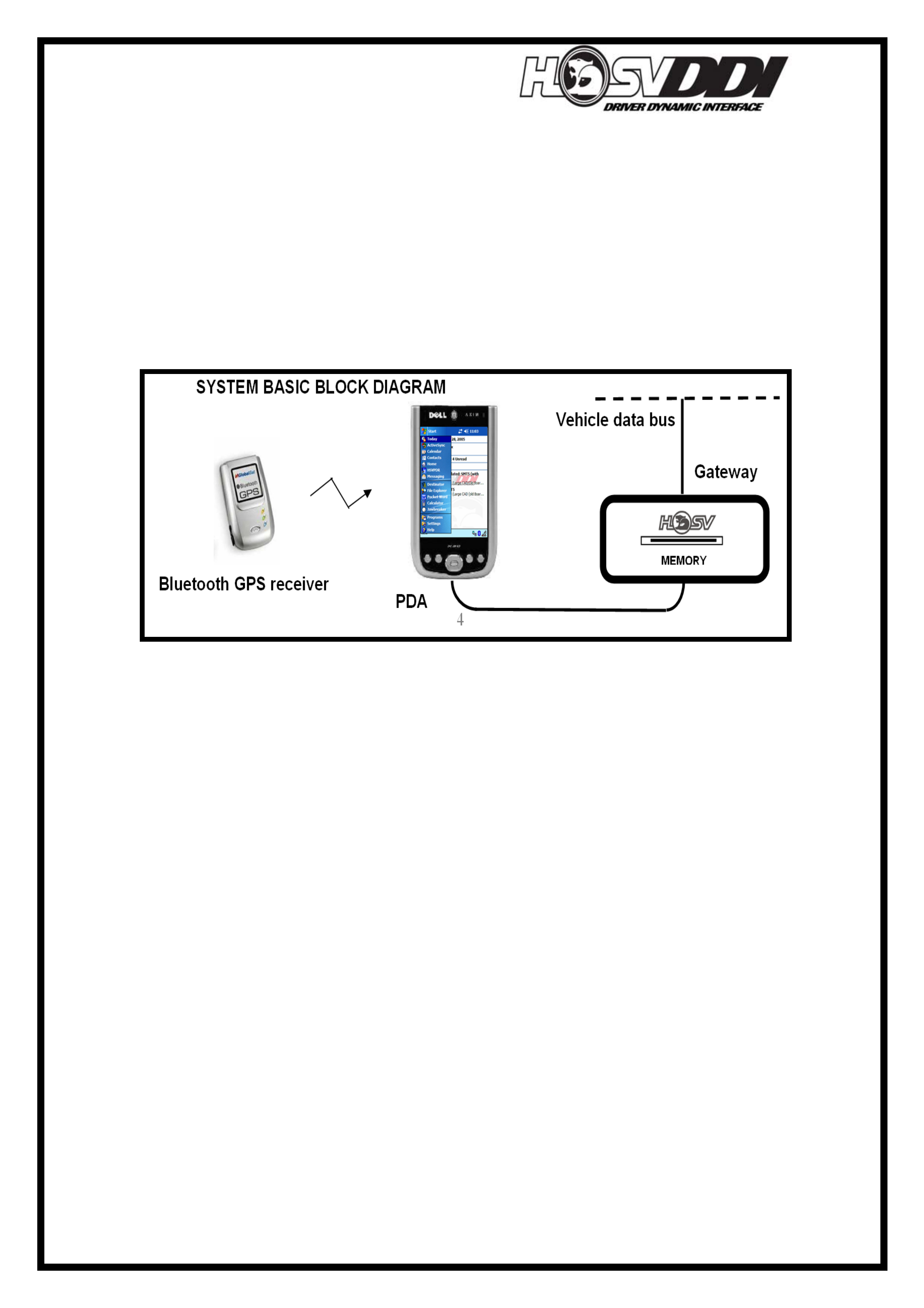
Above, is shown a basic block diagram of the HSVDDI system. The Bluetooth GPS
receiver is connected wirelessly to the PDA/Pocket PC. The Bluetooth GPS Receiver
is exclusively used by the PDA/Pocket PC via Destinator GPS software. The
PDA/Pocket PC may need to be ‘Paired’ to the Bluetooth GPS unit, in order to obtain
correct operation. Please refer to the ‘Quick Reference Guide’ located inside the
HSVDDI User Manual to ‘Pair’ the Bluetooth GPS Receiver to the PDA/Pocket PC.
The Gateway is connected to the Vehicle data bus and interprets and records data to
the SD card located inside Gateway memory slot. This Gateway also converts vehicle
data into messages that the PDA can read and display.
The PDA/Pocket PC is the User Interface. This device allows user input from the
driver as well as displaying data in several different modes. The PDA/Pocket PC is an
important tool when trying to diagnose faults with the system.
HSVDDI System Diagnostics
4
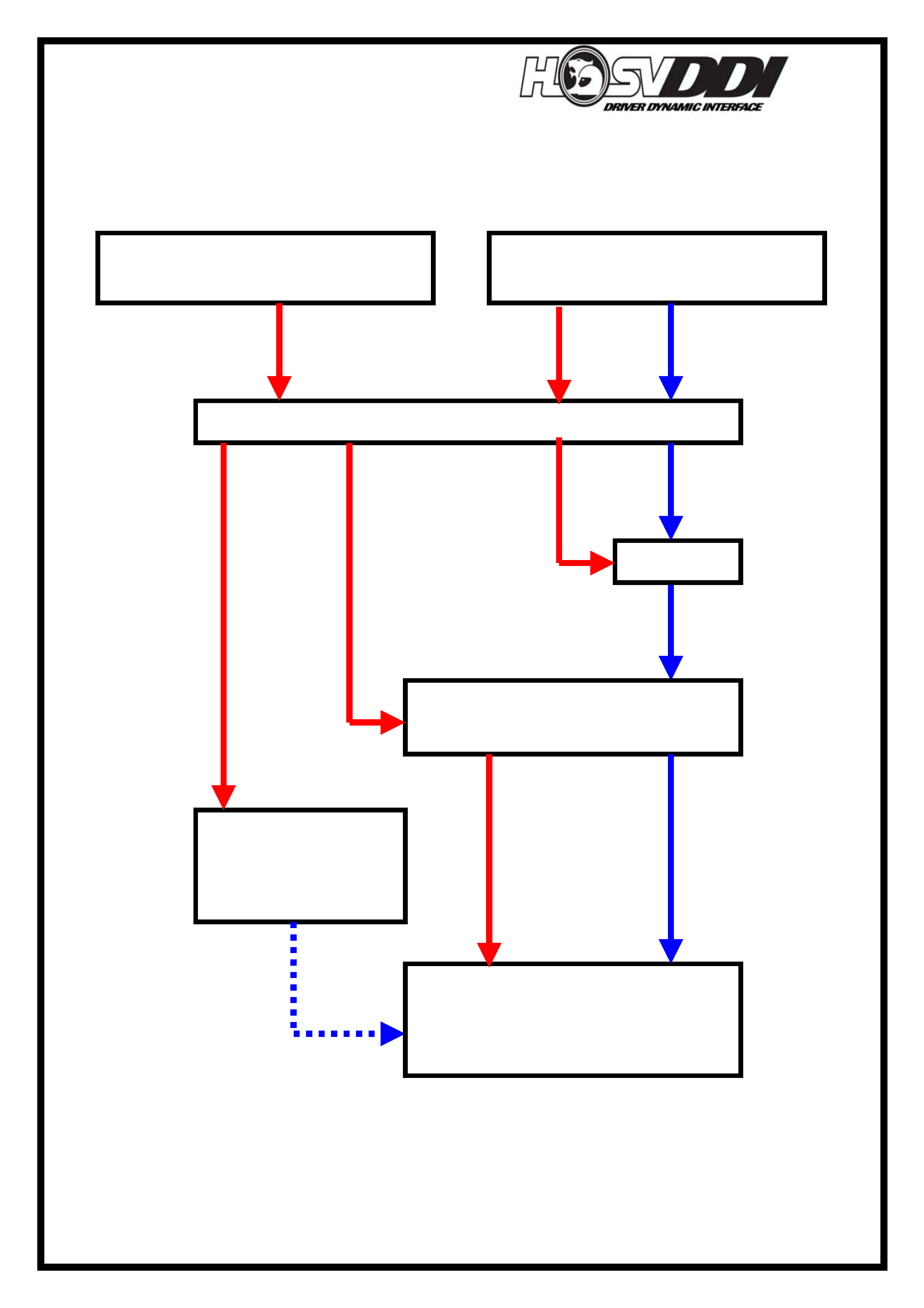
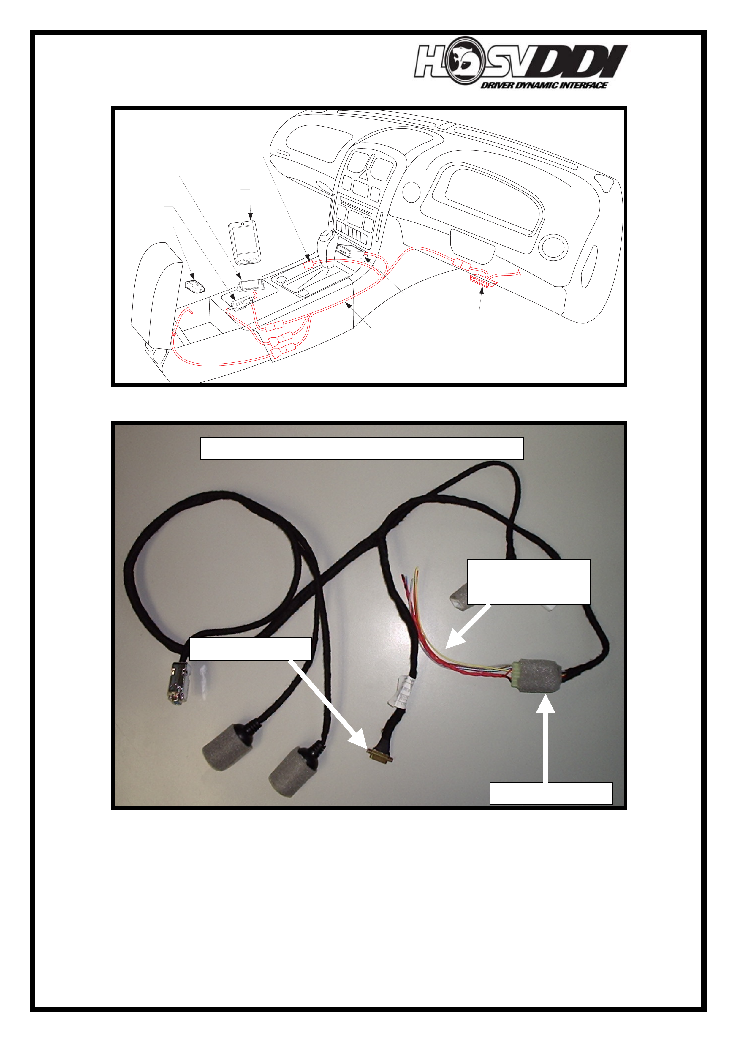
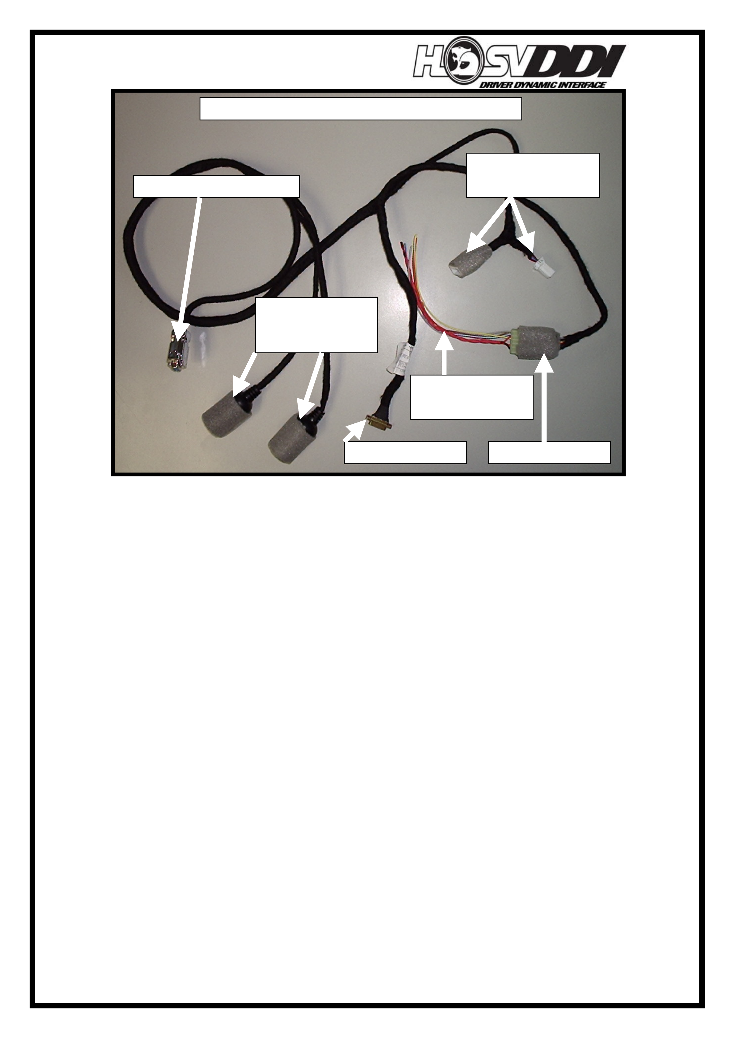
The Diagram below shows the basic outline for connectors, devices, and looms within
the HSVDDI system. Red arrows indicate Power delivery to the looms/modules and
Blue arrows indicate data flow through looms/modules.
Vehicle Data and Gateway
Powe
r
(
From Tech 2 ALDL
)
Vehicle Inte
g
ration Harness
(
VIH
)
Vehicle Power (From
Tele
p
hone Connector
)
Gatewa
y
Adapter – Serial to PDA
including 12V Charge
Wireless
Bluetooth GPS
Receiver
PDA/Pocket PC

HSVDDI System Diagnostics
5
Initial Checks
- Check that the Red LED light on the Gateway is on. This LED indicates that
the gateway has power supplied to it. The LED will also blink continuously
when performing an ‘Autonomous’ run. ALL other times the LED should be
solid Red. If this is not the case, check the connection to the back of the
gateway and the connection at to the breakout, located near the ALDL Tech 2
connector.
- Ensure that you have an SD media card plugged into the Gateway memory
slot. The DDI system will not function or record data if there is no memory
card inserted into Memory card slot. If the user tries to start the PDR
application without an SD card in the slot, the following message will be
displayed on start-up:
Problems and Fixes
Bluetooth GPS will not Get Satellite Reception.
Fix this problem by pairing the Bluetooth GPS receiver. Refer to the ‘Quick
Reference Guide’ located inside the HSVDDI User Manual to ‘Pair’ the unit to the
PDA/Pocket PC.
There are no Hardware diagnostics for the Bluetooth GPS module because it has a
wireless link to the PDA/Pocket PC for its communications. The only hardware which
is associated with the Bluetooth GPS module is the Charging circuit, which is covered
under ‘GPS Receiver will not Charge in Vehicle.’
.
If any problems exist they are more than likely going to be software issues. The first
point to look at is to see if the units are paired. This is covered in depth inside the
HSVDDI Owners Manual, under ‘Quick User Guide, Section 2 Pairing/Linking the
PDA to GPS Receiver.
For further information refer to the complete Owners manual for the Destinator GPS
system on the Destinator CD-ROM. There is also an Owners CD-ROM contained
inside the Bluetooth GPS Receiver BT-338 box. This CD-ROM also includes
instructions on how to pair the Bluetooth GPS Receiver and PDA/Pocket PC. Inside
these manuals are in-depth explanations and solutions for any problems you may
encounter. Please refer to References section at the end of this document for more
information.
Bluetooth GPS Receiver will not pair to PDA/Pocket PC
- Is Bluetooth Enabled on the PDA/Pocket PC? If not please refer to Quick User
Guide Section 2 Pairing/Linking the PDA to GPS Receiver.
- Is the Bluetooth GPS Receiver turned on?
- Has the Bluetooth GPS Receiver battery gone flat?
- If it has gone flat, ensure it is plugged into the vehicle.
- Are the LED’s on the topside of the Bluetooth GPS Receiver flashing/active?
- If the Blue and Green LED’s on topside are flashing, then generally the unit is
OK. If the Yellow LED is on, the unit needs to be charged. To charge unit,
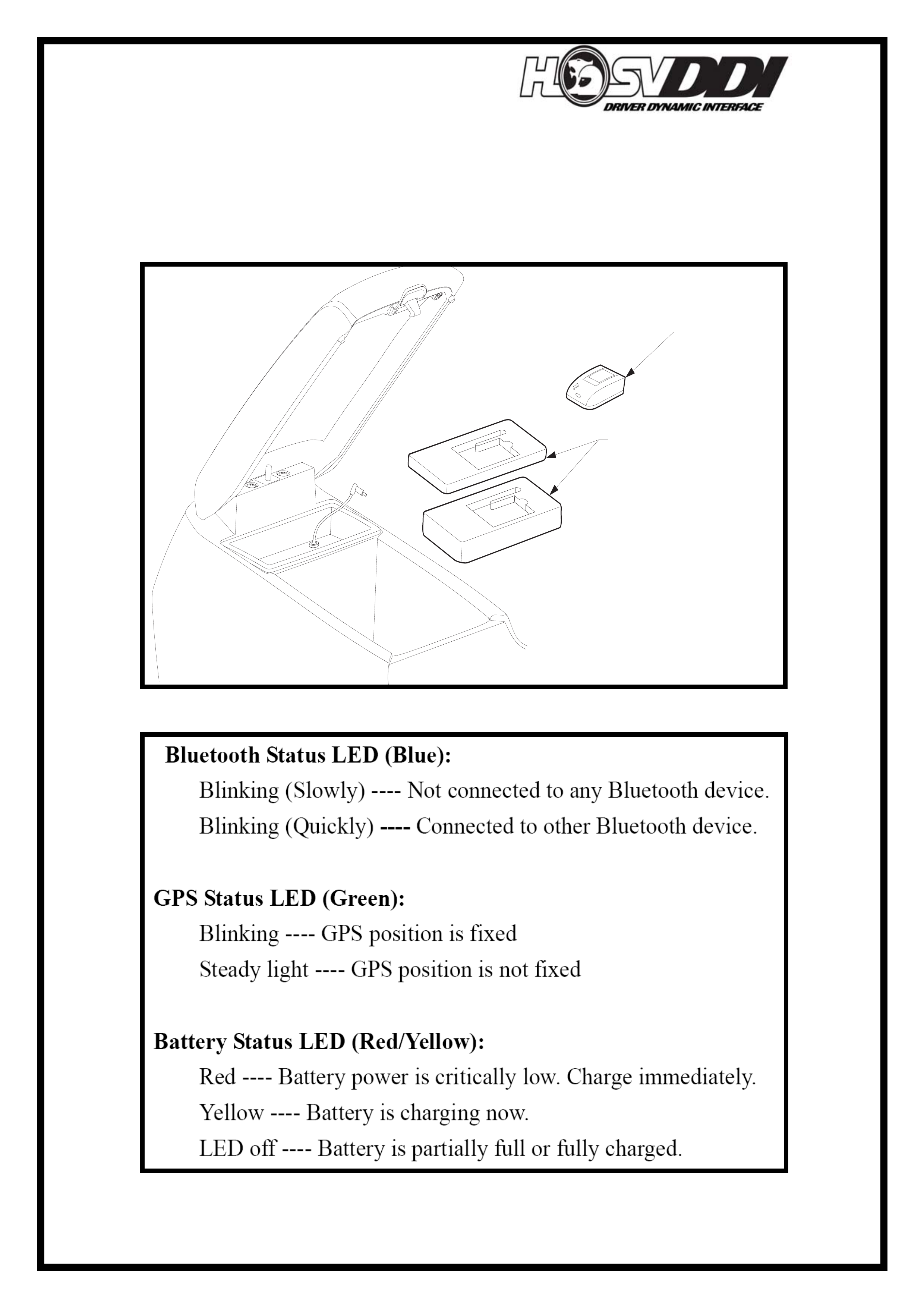
HSVDDI System Diagnostics
6
insert into location shown below and insert charging jack into side of
Bluetooth GPS Receiver.
- Refer to the following table for LED operation and indication of the Bluetooth
GPS Receiver status.
BT-338 Bluetooth GPS Receiver charging/operating location.
DATE
ISSUE DATED
AUTH'Y
CK.
SYM
AUTH'Y
REVISION RECORD
DATE
SYM
SIGNATURES ON
ORIGINAL APPROVAL
DR.
ADVANCED AUTOMOTIVE DESIGN AND ENGINEERING
12I-050002
INSTRUCTION DRAWING.
A4
SIZE
RECIEVER GPS BLUETOOTH
REVISION RECORD
PRELIMINARY ISSUE
CK.
NAME
PART NO.
CK.
REFERENCE
DWG.
DR.
DATE:
APPR
APPR
DR.
12F-050604
RECIEVER GPS
BLUETOOTH
A206050601
FOAM INSERT
GPS RECEIVER
BT-338 Bluetooth GPS Receiver LED Function.
HSVDDI System Diagnostics
7
No GPS Reception.
- Check that the Bluetooth GPS Receiver and PDA/Pocket PC are paired.
- Refer to Quick User Guide Section 2 Pairing/Linking the PDA to GPS
Receiver to perform this.
- Is Bluetooth Enabled on the PDA/Pocket PC? If not please refer to Quick User
Guide Section 2 Pairing/Linking the PDA to GPS Receiver.
- Is the Bluetooth GPS Receiver turned on?
- Has the Bluetooth GPS Receiver battery gone flat?
- If it has gone flat, ensure it is plugged into the vehicle.
- Are the LED’s on the topside of the Bluetooth GPS Receiver flashing/active?
- If the Blue and Green LED’s on topside are flashing, then generally the unit is
OK. If the Yellow LED is on, the unit needs to be charged. To charge unit,
insert into location shown below and insert charging jack into side of
Bluetooth GPS Receiver.
- Refer to the table for LED operation and indication of the Bluetooth GPS
Receiver status on Page 06 of this document.
- Is the GPS receiver located in its original position? If not place it in
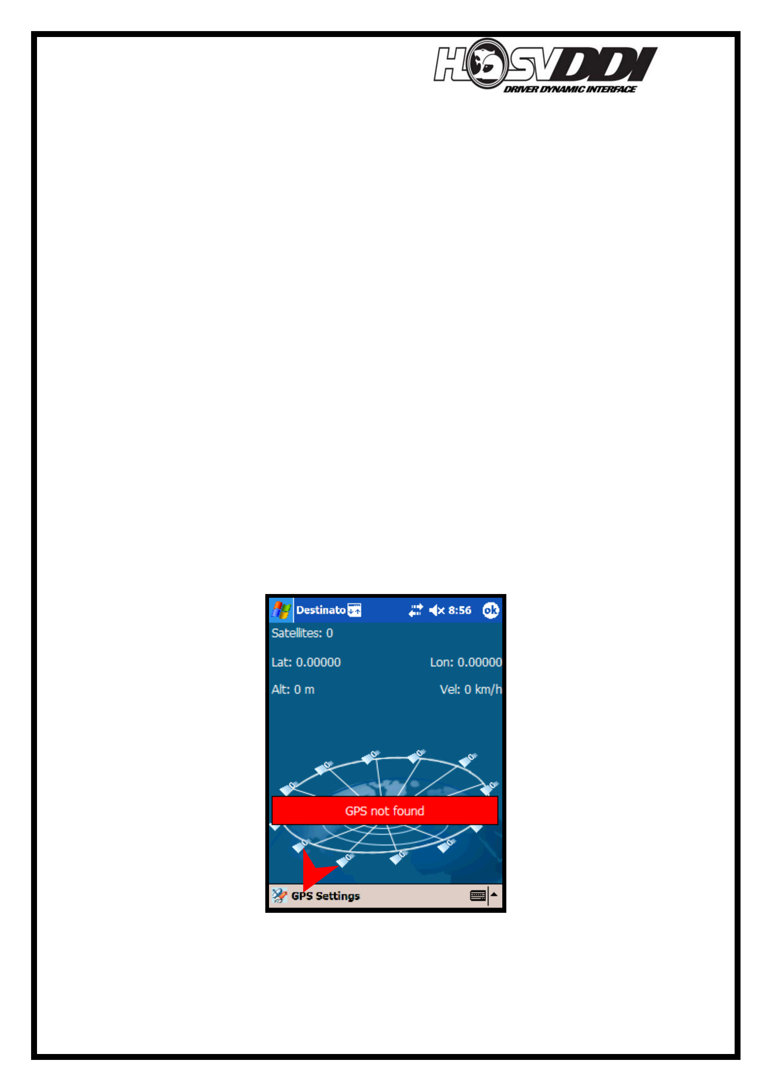
Error Message “GPS Not Found”
- Please ensure that you have paired the unit before starting the Destinator
software. For instructions on how to do this Refer to Quick User Guide
Section 2 Pairing/Linking the PDA to GPS.
- If you have paired the devices and still get the following message, then follow
below.
- Select ‘GPS Settings’ indicated above by the red arrow.
- This will take you to the following screen.
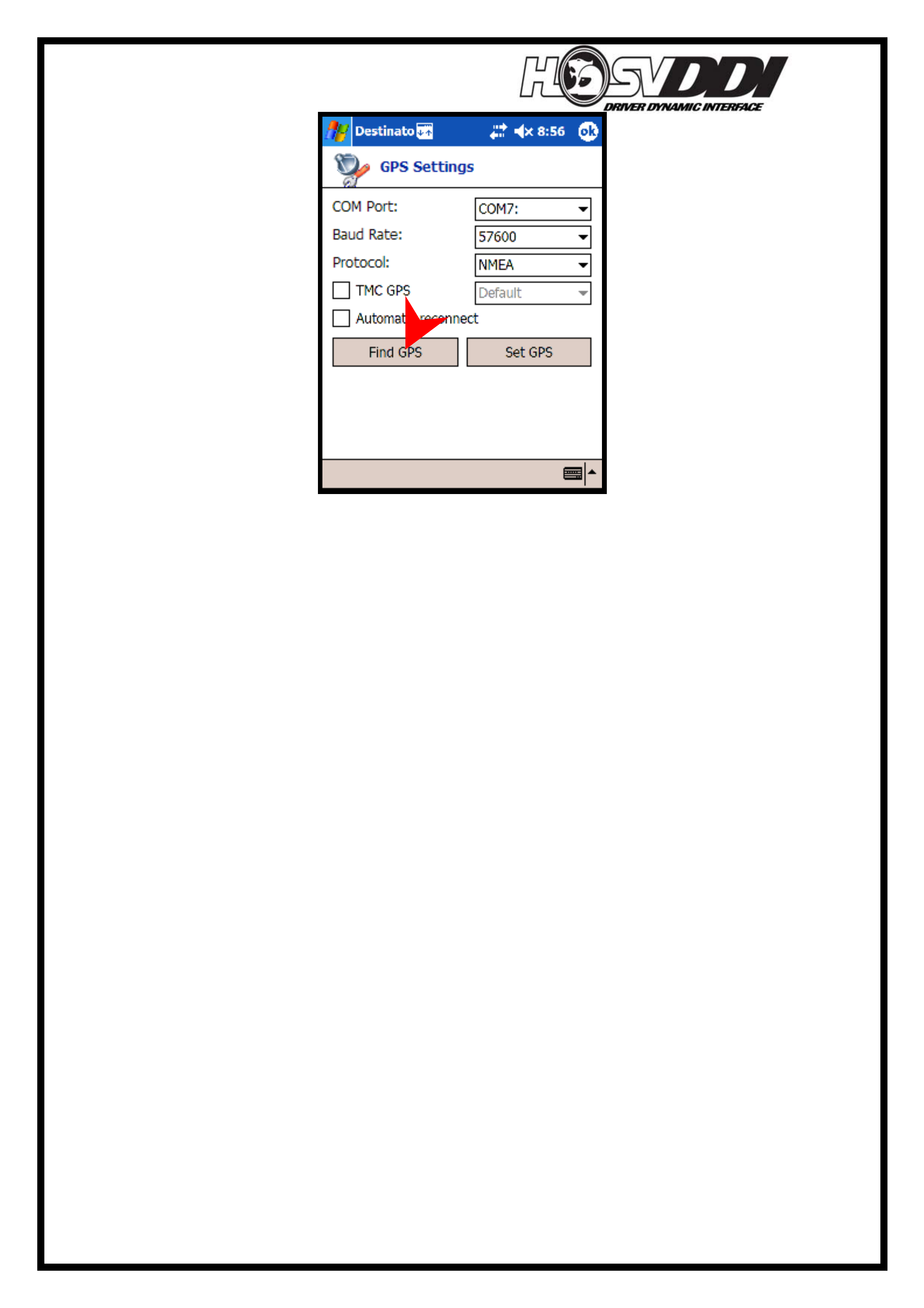
HSVDDI System Diagnostics
8
- Select ‘Find GPS’. Ensuring that when you do this the Bluetooth GPS receiver
is switched on and the battery is not flat.
- The PDA will then automatically search through and select all the correct
default setting to allow communication between the PDA/Pocket PC and the
Bluetooth GPS receiver.
- This process should only need to be done once, when initially starting the GPS
software. If you perform any resets on the PDA/Pocket PC then this process
will need to be done.
- Once this process is complete, it should not need to be done again unless the
PDA undergoes a Reset.
- PLEASE NOTE: This process will not work if the Bluetooth GPS Receiver
has not been paired to the PDA/Pocket PC.
HSVDDI System Diagnostics
9
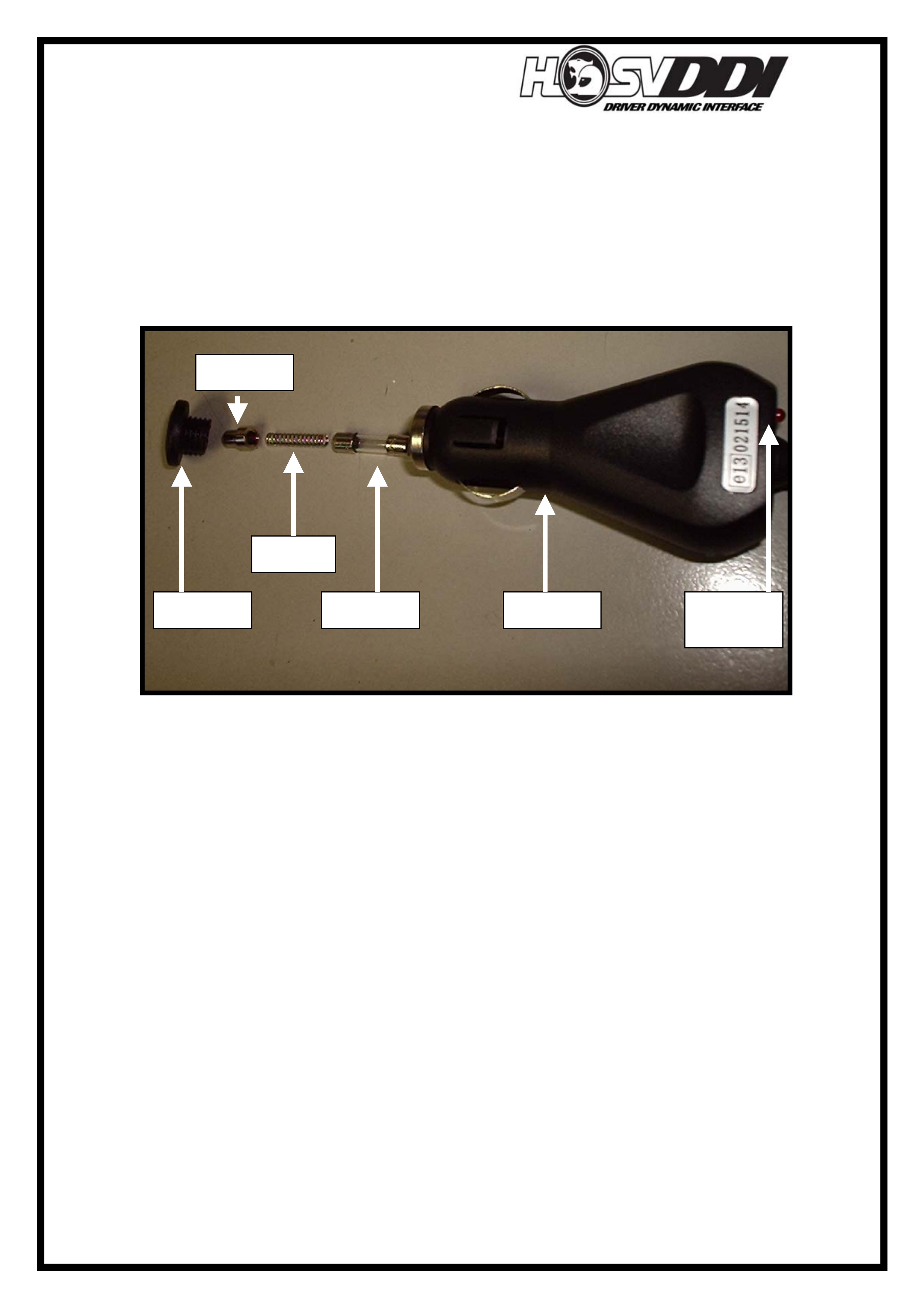
GPS Receiver will not Charge in Vehicle.
The Charging circuit for the Bluetooth GPS receiver consists of a male cigarette
lighter (shown below) that encapsulates a 1A fuse behind a spring. Located on the
rear of this plug is a Red LED. This should be on whenever the accessories circuit is
active, if it is not then check fuse. This adapter plugs into the Vehicle Integration
Harness (VIH) under the center console, near the power window switches. An
exploded view of the adapter is shown below.
- If fuse is checked for continuity and intact and Red Power LED is still not
functional, then perform a continuity check on the Vehicle Integration Harness
VIH.
- To perform this continuity check, use the supplied VIH loom drawing and
concentrate on circuits 31 (Ground) and 32 (Accessories 12V)
- These circuits run from the 12V Adapters under the center console over to the
telephone connector, as shown below.
Telephone connector located on the left-hand side of the radio under the plastic trim.
A visual representation of this is shown on the next page, along with pin outs and
functions of the circuits contained within this connector.
Fuse 3A
Spring
Retainer
Tip
Adapter Power
LED
HSVDDI System Diagnostics
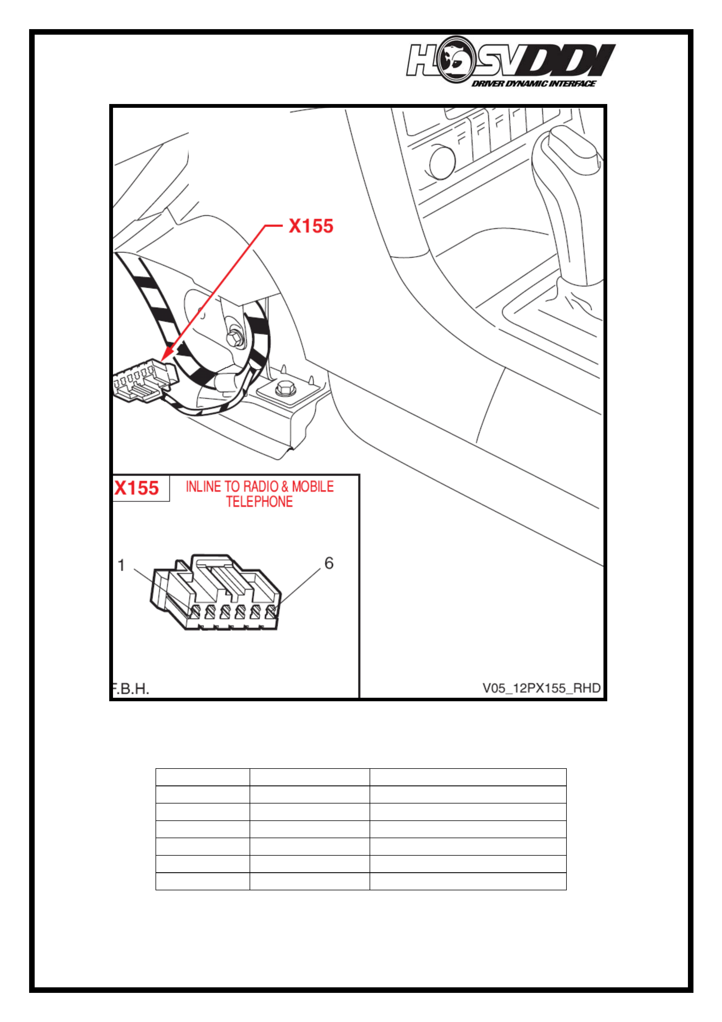
10
Telephone connector location and pin out orientations shown below.
Telephone Connector Pin outs and Usage shown below.
Pin Number Function Used in HSVDDI System
1 Battery No
2 Ground Yes
3 Accessories Yes
4 Mute Signal No
5 Voice Signal No
6 Voice Return No
HSVDDI System Diagnostics
11
Error Message Displayed “No COM Port”
- Check to see if Bluetooth is active on the PDA/Pocket PC
- This can be done by referring to Quick User Guide Section 2 Pairing/Linking
the PDA to GPS Receiver.
- If you have performed the Pairing/Linking Process and also performed the
previous step of ‘GPS Not found’. You should be able to start and run the
Destinator software.
Gateway LED is not active IE. Solid OFF even when Ignition is ON?
- Refer to table below for indication of LED function.
Shown below is the Gateway LED Status Chart.
LED Status
Gateway Status Flashing Solid ON Solid OFF
Autonomous Recording X
Live Stream Recording X
Uploading Data X
Inactive/OFF X
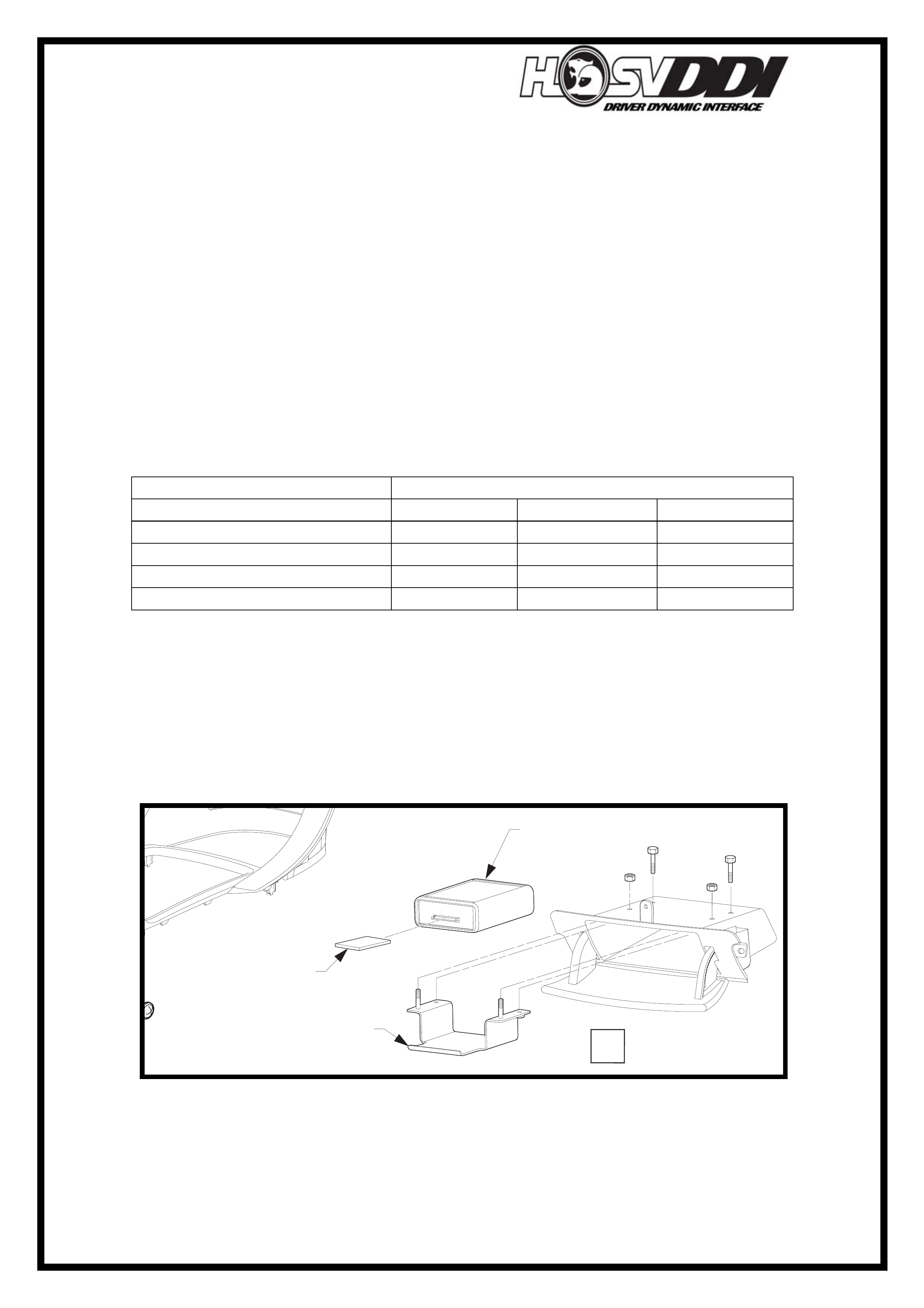
- Once Ignition is turned on, Gateway should immediately ‘Wake Up’, indicated
by the LED going from Solid OFF to Solid ON. Gateway location is shown
below.
- If this is not the case, check continuity of the harness from Gateway connector
over to the ALDL Tech 2 connector. These are shown below.
Location and Mounting of Gateway Module
DATE
ISSUE DATED
AUTH'Y
CK.
SYM
AUTH'Y
REVISION RECORD
DATE
SYM
SIGNATURES ON
ORIGINAL APPROVAL
DR.
ADVANCED AUTOMOTIVE DESIGN AND ENGINEERING
12I-050001
INSTRUCTION DRAWING.
A4
SIZE
HSV DDI
REVISION RECORD
PRELIMINARY ISSUE
CK.
NAME
PART NO.
CK.
REFERENCE
DWG.
DR.
DATE:
APPR
APPR
DR.
VIEW
B
12F-050605
MODULE
GATEWAY
12F-050602
MEMORY CARD
12F-050606
BRACKET
MODULE - GATEWAY
HSVDDI System Diagnostics
12
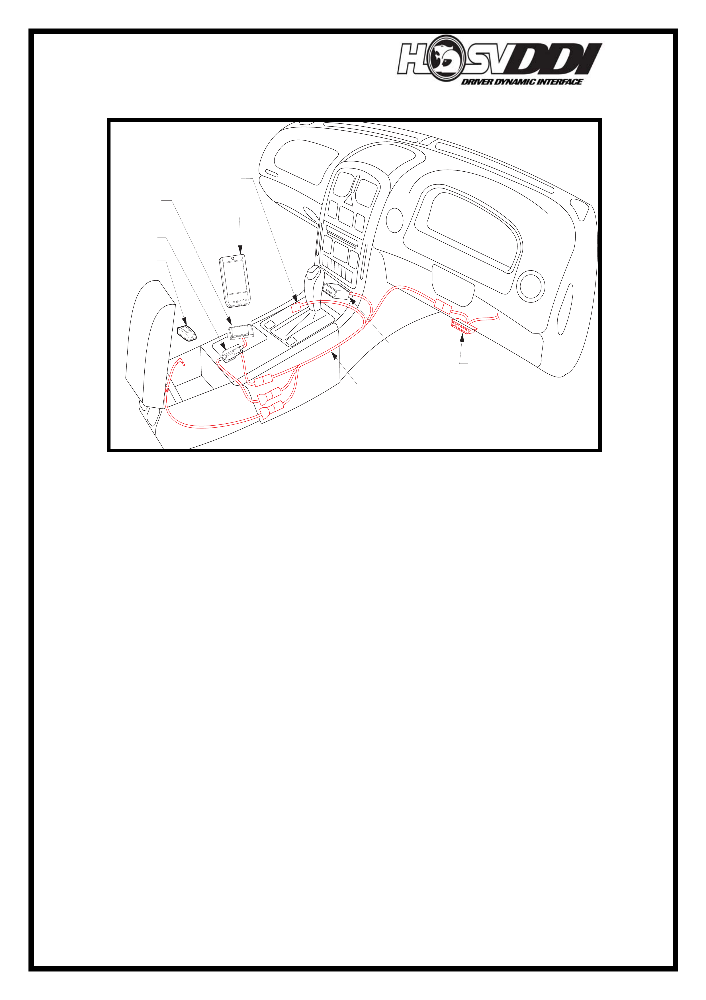
Location and routing of Vehicle Integration Harness within vehicle.
DATE
ISSUE DATED
AUTH'Y
CK.
SYM
AUTH'Y
REVISION RECORD
DATE
SYM
SIGNATURES ON
ORIGINAL APPROVAL
DR.
ADVANCED AUTOMOTIVE DESIGN AND ENGINEERING
12I-050003
INSTRUCTION DRAWING.
A4
SIZE
HSV DDI
WIRING LAYOUT
REVISION RECORD
PRELIMINARY ISSUE
CK.
NAME
PART NO.
CK.
REFERENCE
DWG.
DR.
DATE:
APPR
APPR
DR.
DIAGNOSTIC
CONNECTOR
MODULE
GATEWAY
12F-050605
TO MOBILE
PHONE CONNECTION
CRADLE PDA
12F-050609
PDA
12F-050601
ADAPTER
SERIAL TO PDA
12F-050603
RECIEVER GPS
12F-050604
HARNESS VEHICLE
INTEGRATION
12F-050601
D
E
LL
X50
AXIM
Vehicle Integration Harness.
- Test the following circuits from VIH Loom drawing:
- Circuit 18 (12v Battery)
- Circuit 06 (SDL Ground)
- Circuit 01 (CAN HIGH)
- Circuit 14 (CAN LOW)
Gatewa
y
Connecto
r
ALDL Hardwire
connection
VIH Connecto
r
Vehicle Inte
g
ration Harness
(
VIH
)
- 12H-050601
HSVDDI System Diagnostics
13
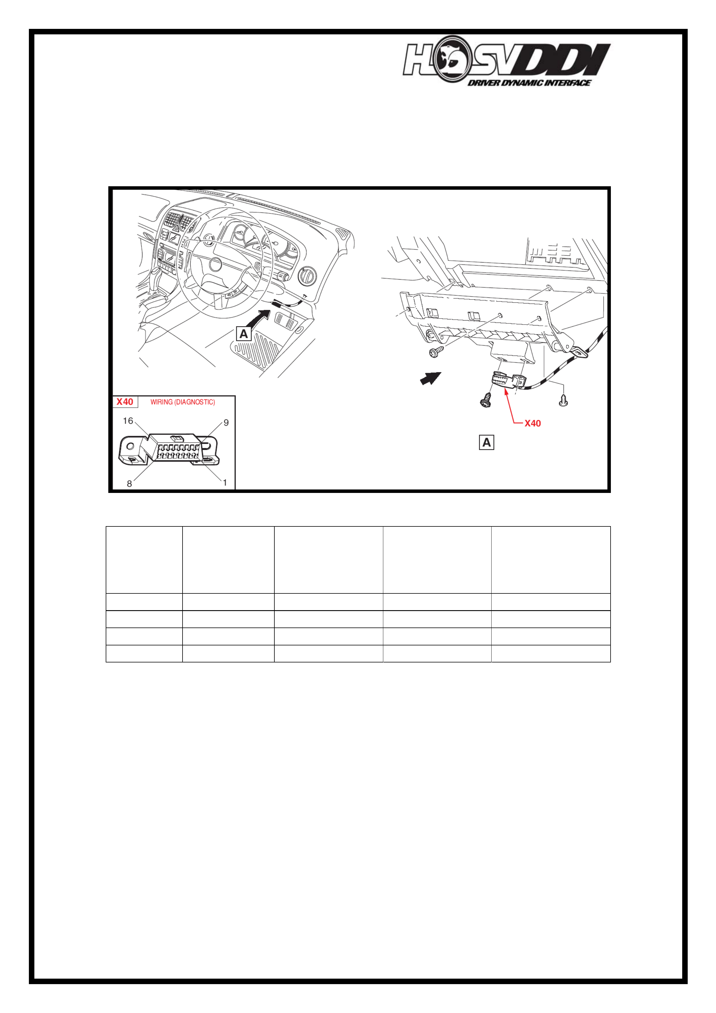
NOTE: The ALDL Hardwire Connection, shown above, is hardwired into the ALDL
connection. So when performing a continuity check, be sure to check from the ALDL
connector (shown below) and not the VIH connector. Otherwise you might be missing
a problem between VIH connector and ALDL.
ALDL Tech 2 connector, shown below.
ALDL Tech 2 and VIH Connector Pin outs shown below.
ALDL
Tech 2
Pin
Number
Function Used in
HSVDDI
System
VIH Connector
Terminal
Number
VIH Loom
Drawing Circuit
Number
5 SDL Ground Yes 3 6
6 CAN High Yes 4 1
14 CAN Low Yes 6 14
16 12V Battery Yes 7 18
NOTE: No other pins are used, at this stage in the ALDL Tech 2 connector to run the
HSVDDI system.
Gateway LED is flashing?
- This is normal operation under an ‘Autonomous’ Run, or when uploading
information from the Gateway to the PDA/Pocket PC.
- Refer to table on Page 09 of this document for Gateway LED functionality.
- If you need to stop an ‘Autonomous Run’, please refer to HSVDDI User
Manual.
HSVDDI System Diagnostics
14
PDR Application keeps asking for Security Code.
- When starting the PDR software from the PDA/Pocket PC, the software
continually asks for the PDR Security Code.
- If you have this problem, then the PDR application software was not installed
correctly after a Reset or similar.
- To rectify this problem, follow the correct software installation procedures
outlined on the HSVDDI Disc:\InstallerGuide\HSVPDR.
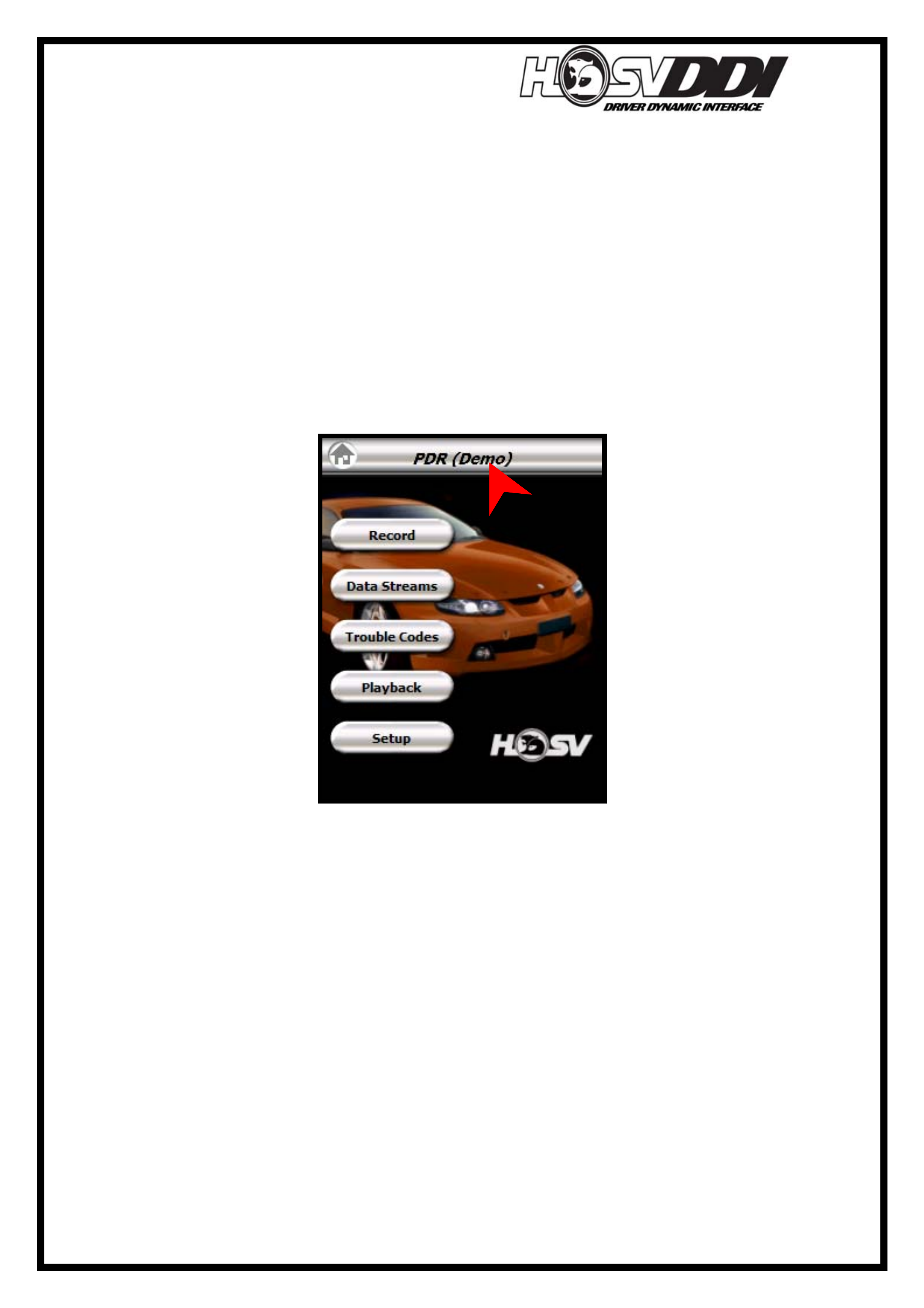
PDR Application - Cannot Exit “Demo Mode”
- PDR Application is in Demo Mode, as shown below
- To solve this problem, select ‘Setup’
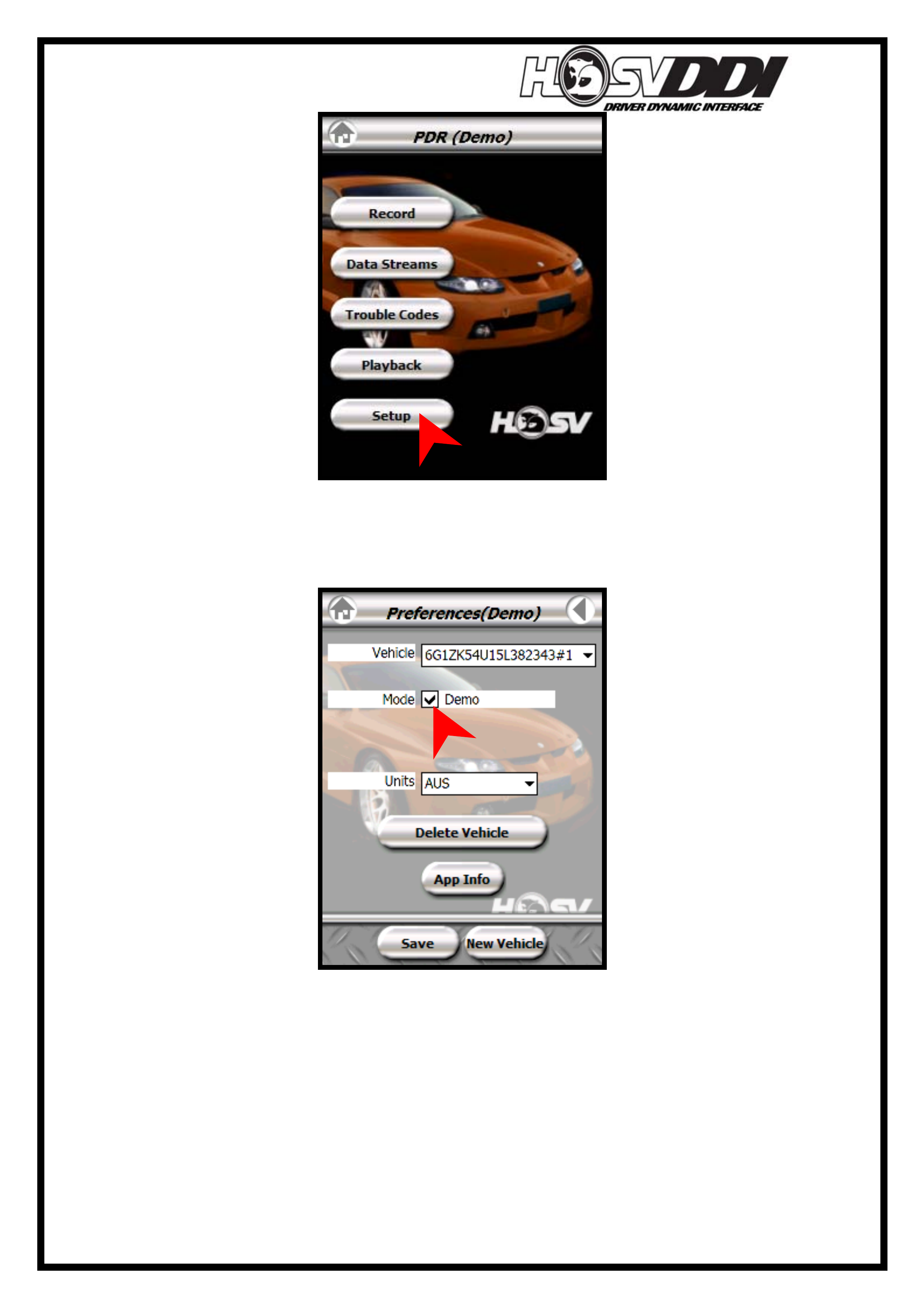
HSVDDI System Diagnostics
15
- Then unselect the ‘Demo’ check box, as shown below
- Then select ‘Save’ down the bottom of screen as indicated by the red arrow.
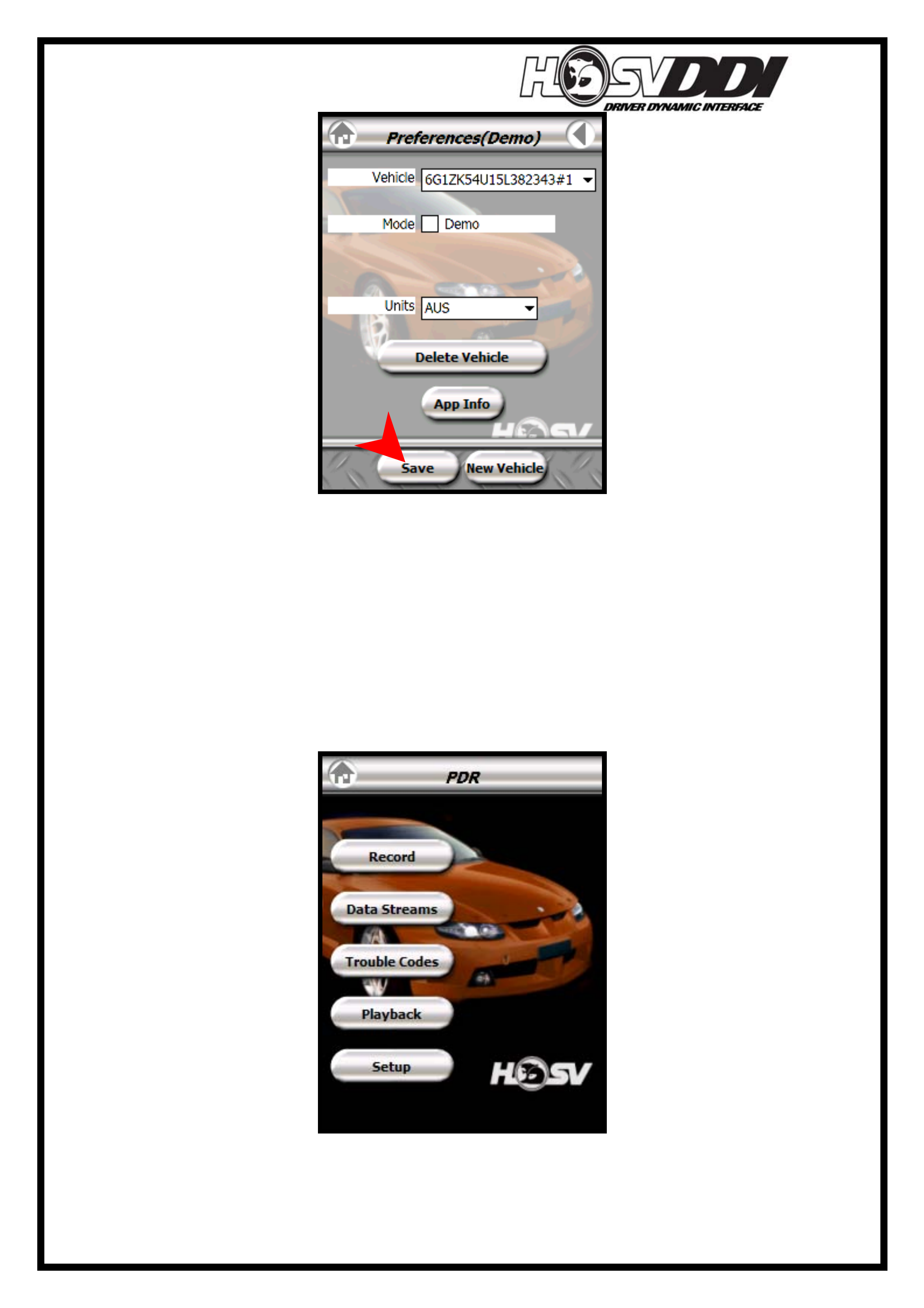
HSVDDI System Diagnostics
16
- Once ‘Save’ is selected, the PDR Application will take the user back to the
home screen, as shown below. Observe the fact that no ‘Demo’ appears inside
brackets up the top of screen, as before. This is your indication that Demo
mode has been disabled. PDR Application should perform as normal now and
be able to record real data.
HSVDDI System Diagnostics
17
- This DEMO setting can be toggled ON and OFF by following the same
procedure as listed above. The main point of enabling DEMO mode is to
display the features of the PDR software without having it connected to the
vehicle. Sample data is used to show examples of what the software is capable
of.
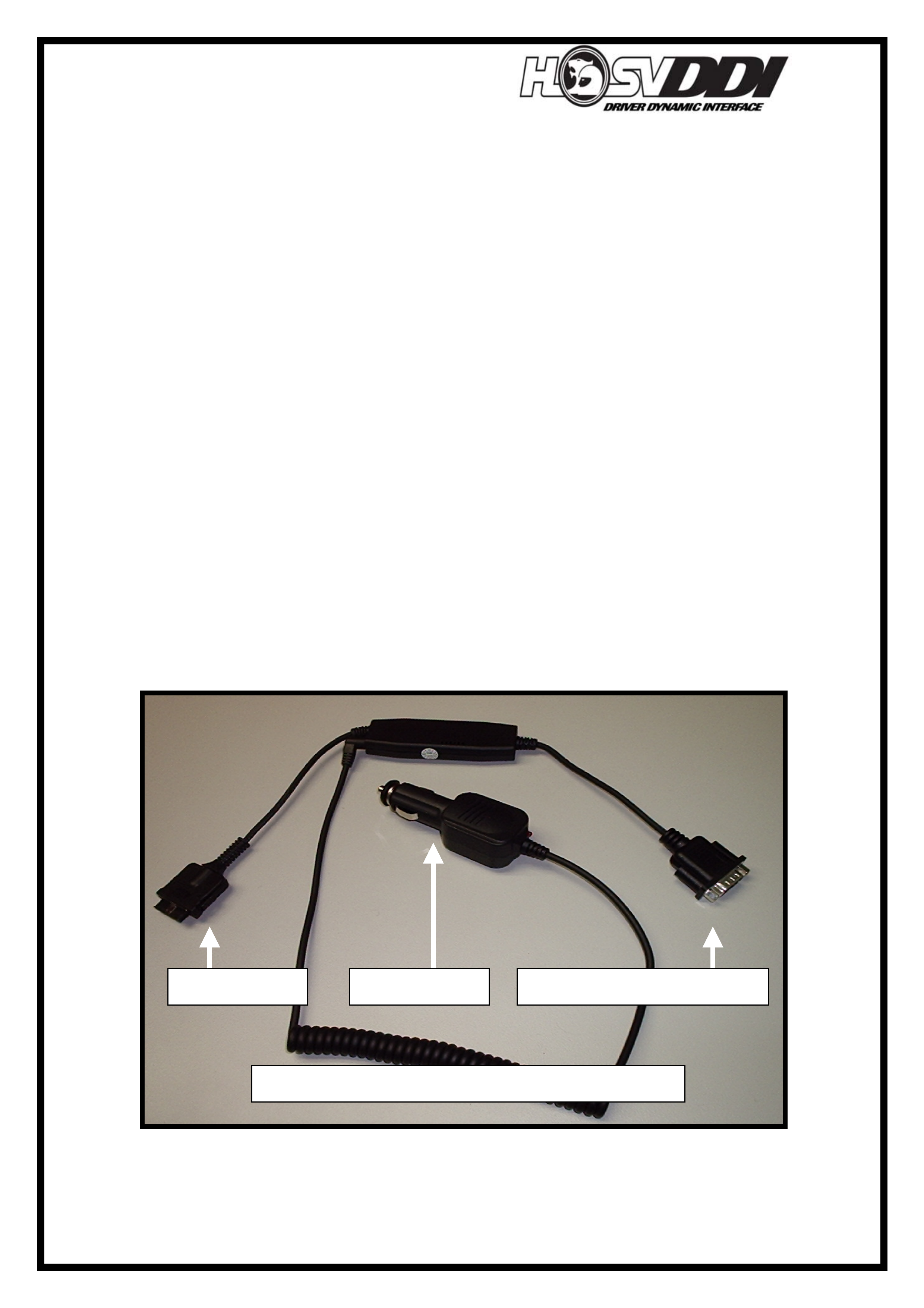
PDA/Pocket PC will not charge in Vehicle.
The Charging circuit for PDA/Pocket PC is incorporated into the Serial adapter cable,
as shown below.
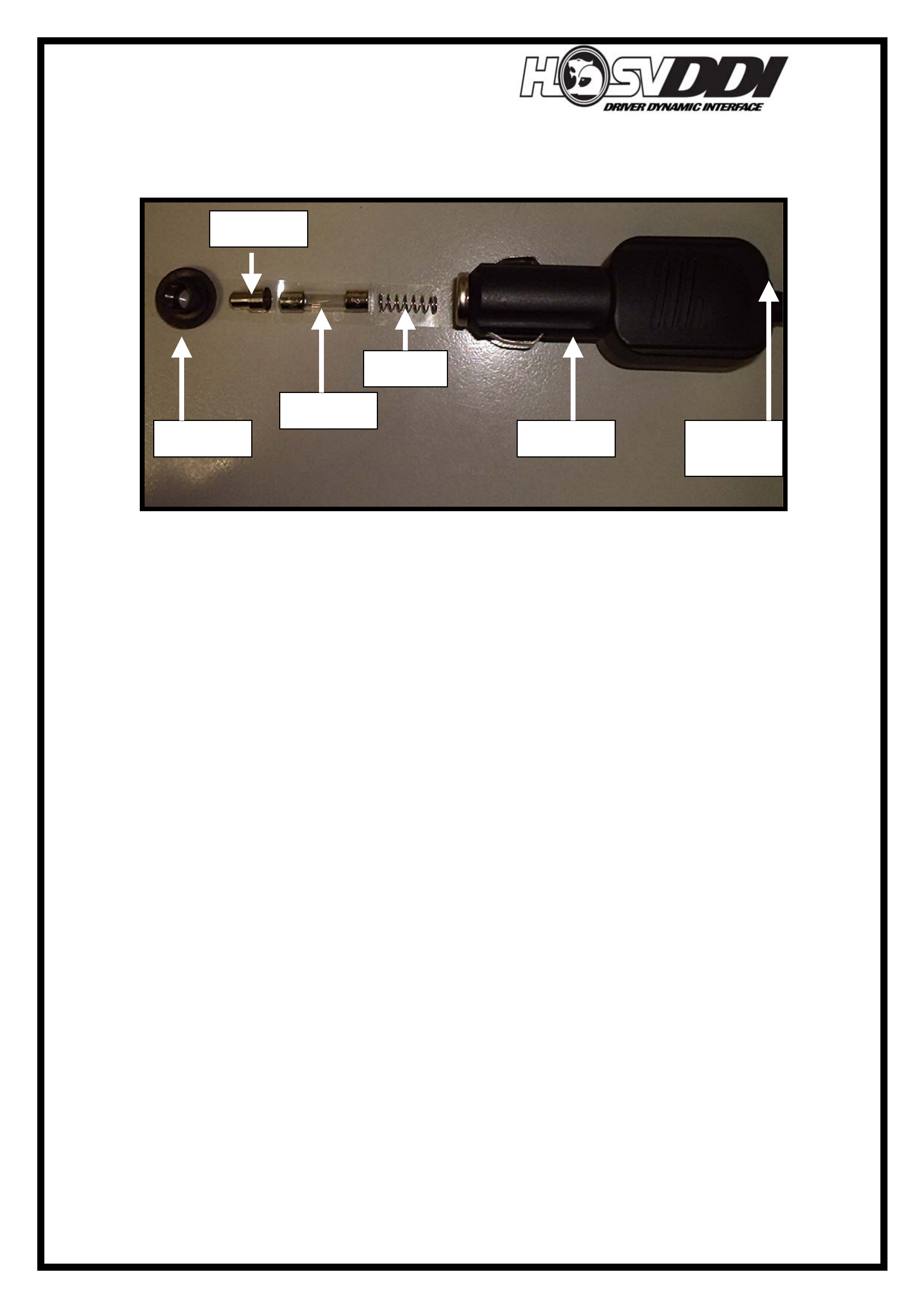
It consists of a male cigarette lighter (shown below) that encapsulates a 3A fuse
behind a spring. Located on the rear of this plug is a Red LED. This should be on
Adapter – Serial to PDA and 12V Charge 12F-050603
DB9 9-Pin Connects into VIH PDA connector 12V Adapter
HSVDDI System Diagnostics
18
whenever the accessories circuit is active, if it is not then check fuse. This adapter
plugs into the Vehicle Integration Harness (VIH) under the center console, near power
window switches. An exploded view of the adapter is shown below.
Neither Bluetooth GPS Charge light, or PDA/Pocket PC charge light operates
when Ignition of the vehicle is ‘ON’
- Check ‘Power’ LED’s on the rear of Bluetooth GPS Charger and PDA/Pocket
PC Charger. They should illuminate when vehicle Ignition is ‘ON’. If they
don’t then:
- Check fuses in both the Bluetooth GPS Charger and PDA/Pocket PC Charger
to ensure they are intact. If they are intact then:
- Check to ensure that the VIH Harness is plugged into the Telephone connector
of Vehicle. If it is plugged in then:
- Check to see if Vehicle Fuse 16 (F16) with a rating of 7.5A is intact. This fuse
is located in the fuse box directly above ALDL Tech2 connector. The fuse is
labeled as: F16 Radio/Nav/Phone.
PDA/Pocket PC will not Respond to User Input.
- The PDA/Pocket PC will not respond to any user input, emitting a dull tone
each time a button/screen is pressed.
- To solve this problem, perform a ‘Soft Reset’ on the device. Refer to Dell
User Manual for instructions on how to do this.
What do the connectors on the Vehicle Integration Harness (VIH) look like and
what do they do?
- The Vehicle Integration Harness (VIH) is shown below.
Fuse 3A
Spring
Retainer
Tip
Power
LED
Adapter
HSVDDI System Diagnostics
19
- The VIH is hardwired into the vehicles Harness, located at the ALDL Tech 2
connector.
- This hardwired section is shown above; it is the unwrapped colored wires that
can be seen above. These are crimped into the back of the ALDL connector.
- The rest of the VIH can be removed or replaced by disconnecting via the VIH
Connector, as shown above.
- The VIH also taps into the Telephone connector of the vehicle in a patch
harness configuration. There is no modification required to implement the
telephone connector setup.
Gatewa
y
Connecto
r
DB9 9-
p
in Serial Connecto
r
12V Adapters for
Serial Cable and
GPS Charge
ALDL Hardwire
connection
Telephone Connector
Patch
VIH Connecto
r
Vehicle Inte
g
ration Harness
(
VIH
)
- 12H-050601
HSVDDI System Diagnostics
20
Where is the Vehicle Integration Harness located in the vehicle and where does it
run?
DATE
ISSUE DATED
AUTH'Y
CK.
SYM
AUTH'Y
REVISION RECORD
DATE
SYM
SIGNATURES ON
ORIGINAL APPROVAL
DR.
ADVANCED AUTOMOTIVE DESIGN AND ENGINEERING
12I-050003
INSTRUCTION DRAWING.
A4
SIZE
HSV DDI
WIRING LAYOUT
REVISION RECORD
PRELIMINARY ISSUE
CK.
NAME
PART NO.
CK.
REFERENCE
DWG.
DR.
DATE:
APPR
APPR
DR.
DIAGNOSTIC
CONNECTOR
MODULE
GATEWAY
12F-050605
TO MOBILE
PHONE CONNECTION
CRADLE PDA
12F-050609
PDA
12F-050601
ADAPTER
SERIAL TO PDA
12F-050603
RECIEVER GPS
12F-050604
HARNESS VEHICLE
INTEGRATION
12F-050601
D
E
LL
X50
AXIM
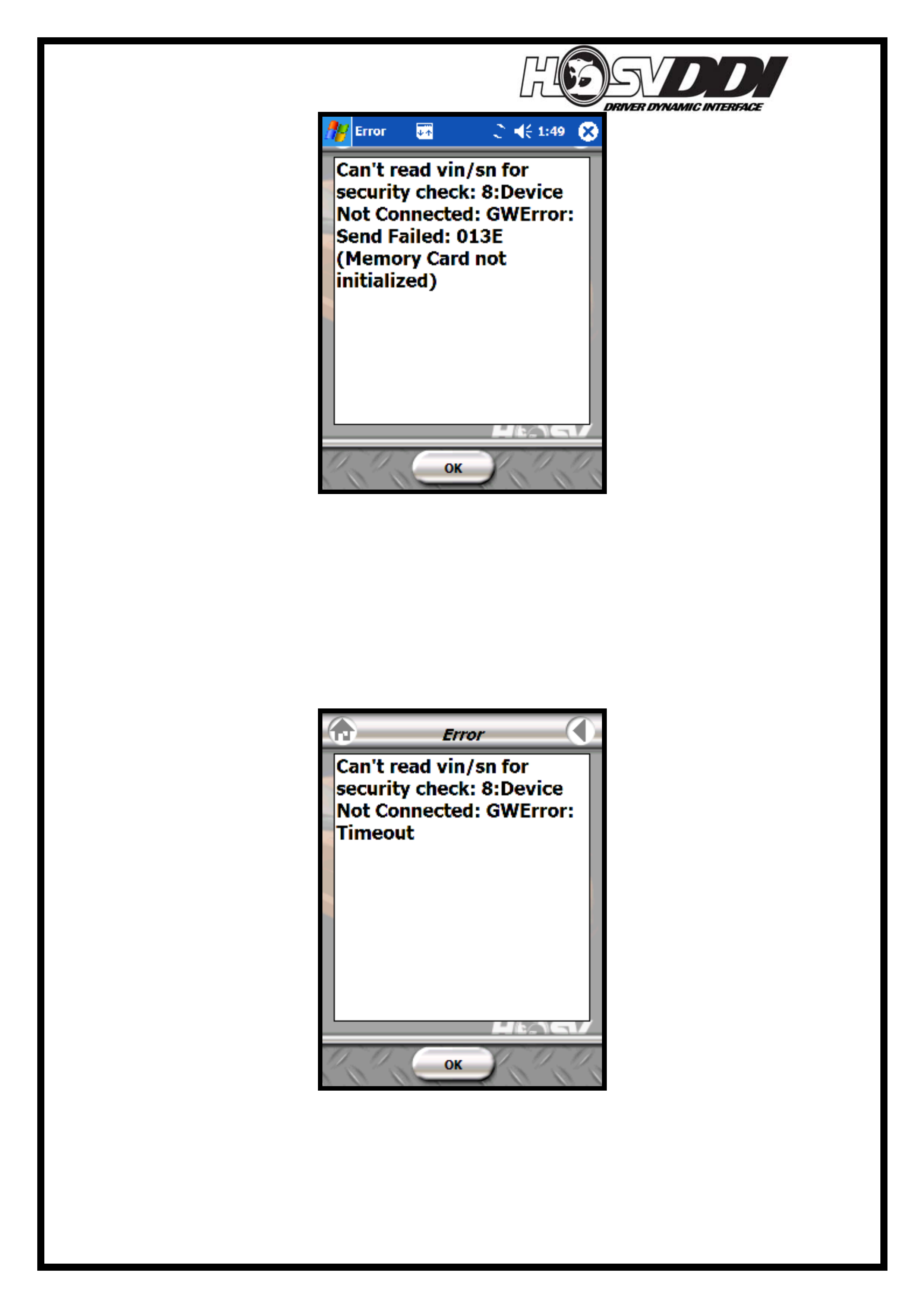
Can’t read Vin/SN for security Check
HSVDDI System Diagnostics
21
- Check that the PDA is correctly mounted and plugged into the vehicle
mounting cradle. Remember that 2 audible clicks, one on each side of the
connector indicates that it is mounted correctly. Refer to page 24 of the
HSVDDI Manual ‘Handling the PDA with Care’ for more information on how
to do this. If the PDA is not connected to the vehicle (Or there is a problem
communicating between the gateway and PDA/Pocket PC) and PDR
application is started up, the following error message will be displayed:

HSVDDI System Diagnostics
22
If this screen is shown while the PDA/Pocket PC is plugged into the vehicle with the
engine running, then complete the following procedure:
1. Remove the PDA/Pocket PC from the cradle and unplug it from the car.
2. Perform a ‘Soft Reset’ on the PDA/Pocket PC. This is done be pressing the
reset button on rear of PDA/Pocket PC with stylus. For more information on
Resets please refer to the Dell Axim PDA/Pocket PC User Manual.
3. Restart the PDR software and try again. Majority of the time, this process of
Resetting will fix the problem. If it does not, then continue to follow these
steps.
Physical Connection Problems from the PDA/Pocket PC over to the Gateway.
The plug you connect into the bottom of PDA/Pocket PC is a fragile device. Care
needs to be taken when removing or installing PDA/Pocket PC into this cradle. Refer
to page 24 of the HSVDDI Owners Manual. That particular plug is connected to a
serial data adapter, which is in turn connected to the Vehicle Integration Harness
(VIH). This VIH then plugs into the rear of the Gateway module and supports the rest
of the DDI system for power and signals.
Communication cannot be established between the PDA/Pocket PC and the
Gateway, please follow these steps:
- Perform Reset on the PDA and retry/restart software to see if this rectifies the
problem. (Refer to User Manual Documentation)
- Check that the Red LED on Gateway is solid Red.
- Check continuity exists between the Gateway circuits and the circuits running
over to the serial data cable. This connector is the DB 9-pin computer
connector located under the center console. Remove the serial connector to
allow checking of the VIH.
- Visually check that there are no bent or dislodged pins on the 25-pin Sub D
Gateway connector. If there are dislodged or bent pins on this connector,
replace the Vehicle Integration Harness, part number: 12H-050601
- If continuity does exist and communications with the Gateway cannot be
established, then replace the Serial Data Communications adapter. Part
number: 12F-050603. If continuity exists between Gateway connector and
DB9 pin connector, but no communications can be established, then replace
the Serial Data Communications Adapter.
HSVDDI System Diagnostics
23
PDR Software won’t work correctly
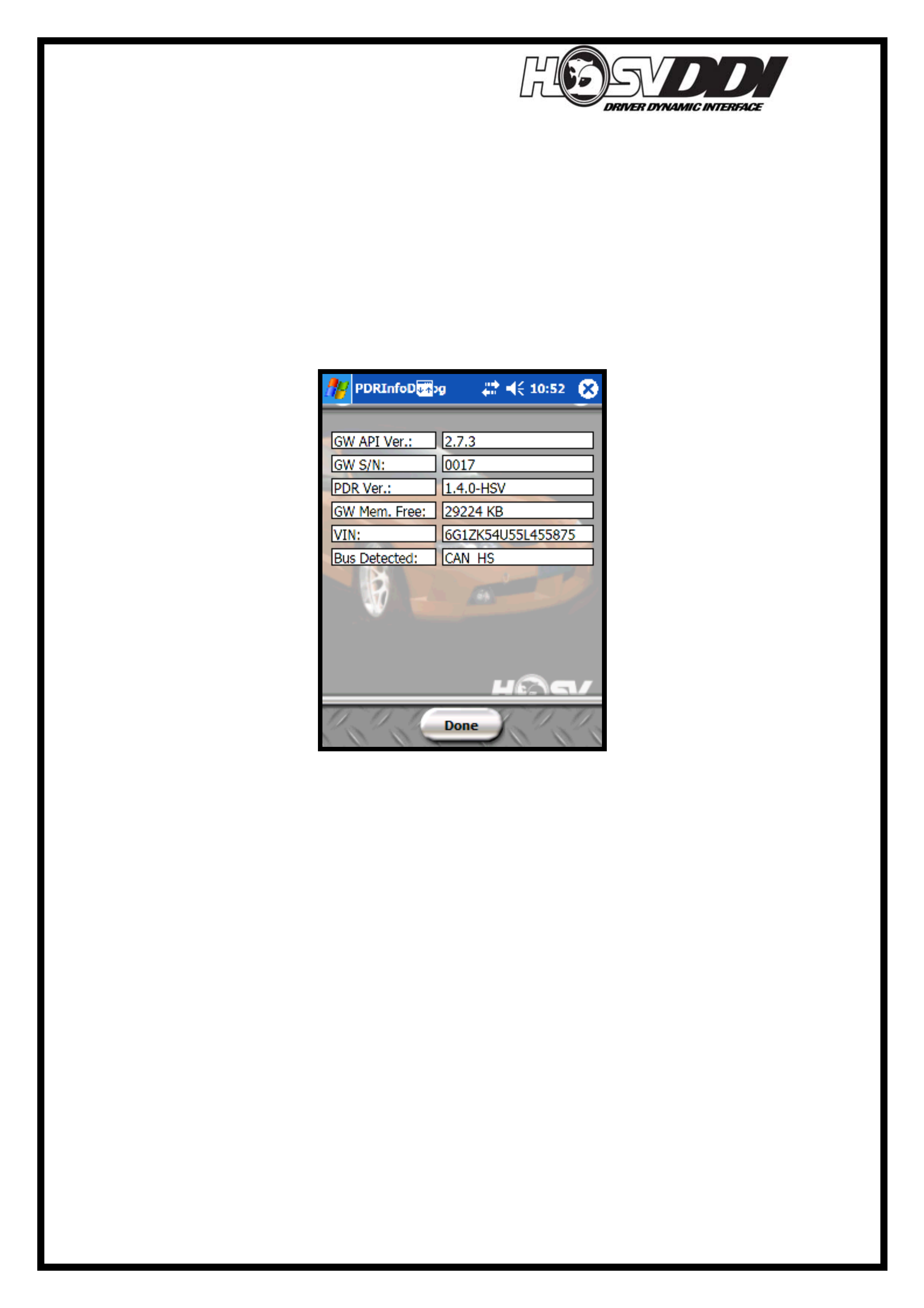
PDR Info Dialog Screen
If PDA/Pocket PC is performing correctly, but PDR software is constantly coming up
with errors or any disconnection/GW Errors, try the following. From the home screen
of the PDA select START > HSVPDR > I AGREE > SETUP > APPINFO. Inside this
screen the user will see following screen.
This screen is very useful in diagnosing faults as it displays all communication
information and software versions. None of these values can be changed by the user;
they are read-only values and in most cases are programmed from the factory. The
APPINFO screen should appear as follows.
What you should see in each of these boxes:
GW API Ver: This is the Gateway firmware number and is programmed from the
factory. The number in here should read 2.7.3, as above.
G/W S/N: This is the Gateway Serial Number. This number is unique to each
vehicle/Gateway. It is the number of that particular gateway. In this instance the
Gateway number is 0017.
PDR Ver: This is the Performance Data Recorder Software Version. The production
released version of the software is 1.4.0-HSV, as shown above.
GW Mem. Free: This displays the available memory left on the Gateway SD card.
Please keep in mind this is NOT the card in the back of PDA/Pocket PC. This value
will constantly change, as the user fills the memory with data and runs. In this
instance the value was 29224 KB (Kilobytes).

HSVDDI System Diagnostics
24
VIN: Stands for Vehicle Identification Number. This is vehicle specific and will vary
with each vehicle. Under normal operating condition the VIN will appear in this
dialog box.
Bus Detected: This indicates the type of Data Communication Bus detected and
should always read CAN_HS (High Speed Controller Area Network)
For example, the following screen shot of the APPINFO screen was taken when the
PDA was not plugged into a vehicle.
HSVDDI System Diagnostics
25
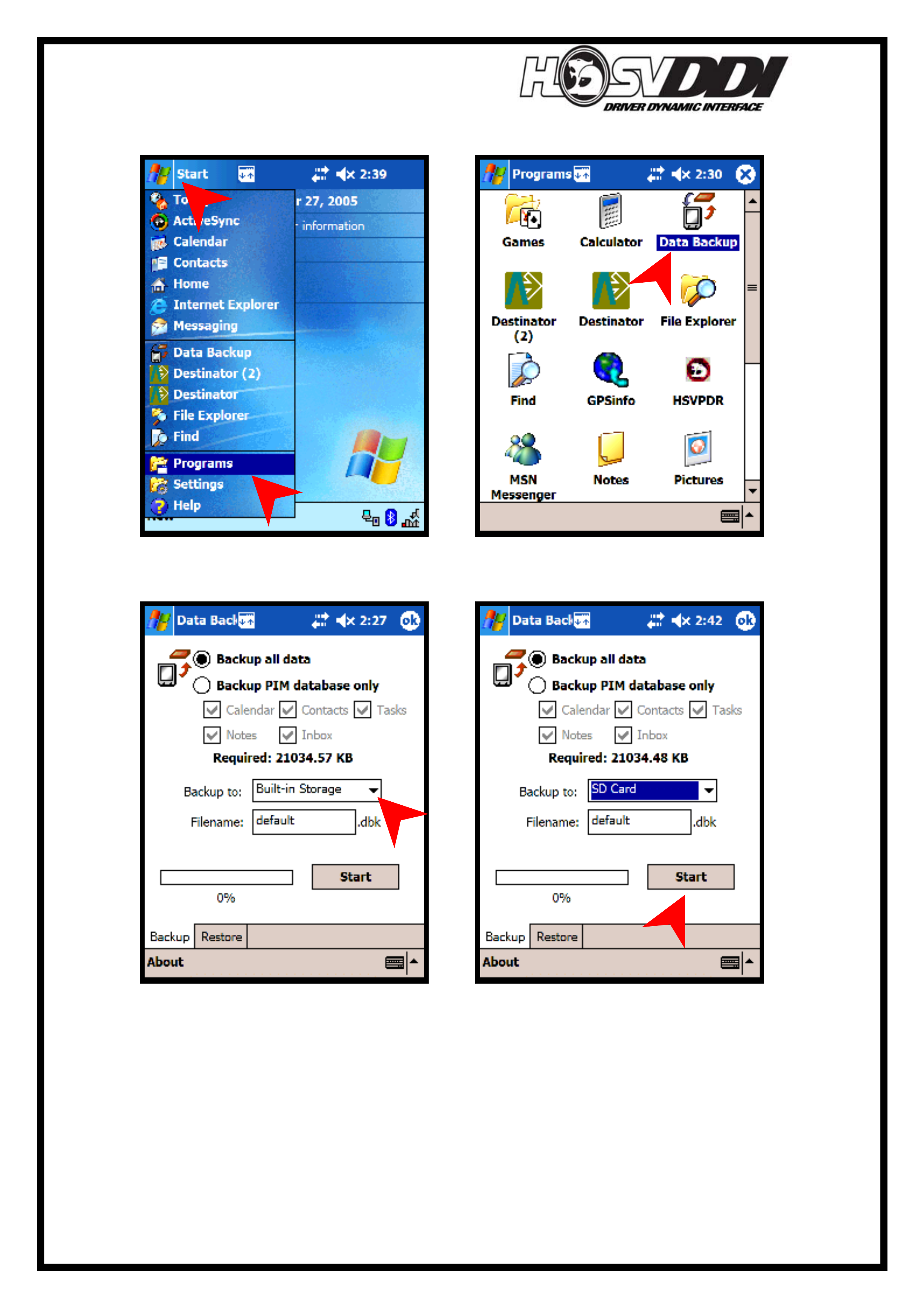
Performing a Backup of your PDA/Pocket PC
- Select ‘Start’ and then ‘Programs’
- Select ‘Data Backup’
- Select ‘Backup to:’ and ensure that you have the SD card selected.
- Select ‘Start’
HSVDDI System Diagnostics
26
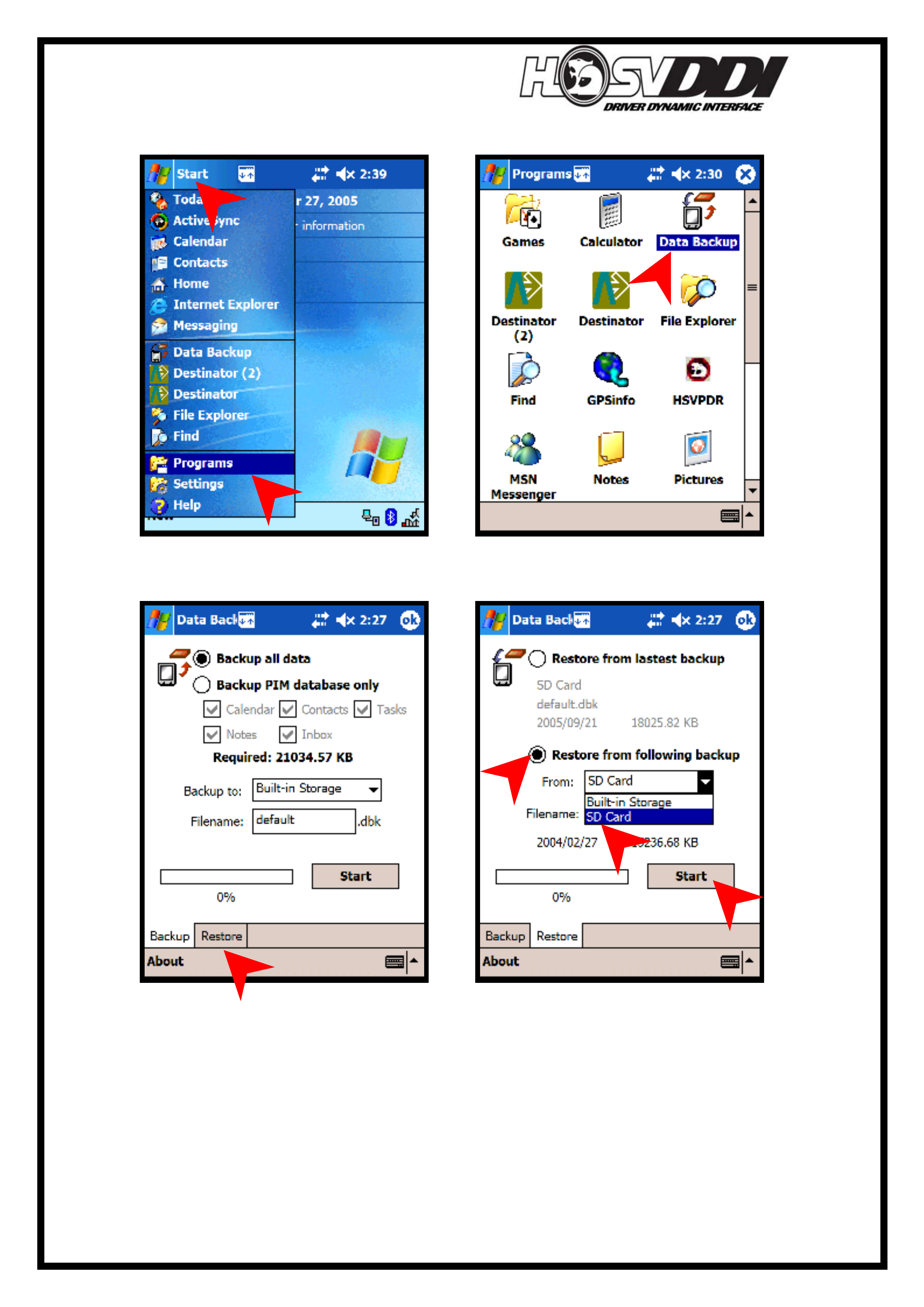
Restoring PDA/Pocket PC from an existing Backup
- Select ‘Start’ and then ‘Programs’
- Select ‘Data Backup’
- Select ‘Restore’
- Select ‘Restore from following backup’ and then select ‘SD Card’
- Select ‘Start’

HSVDDI System Diagnostics
27
References:
User Guides on Disc
DESTINATOR FULL USER GUIDE
Quick Start Guide: Destinator Disc\Quick_Start_Guide\Destinator Quick Start Guide
Full User Guide: Destinator Disc\Indep\Manual\User Guide.pdf
BLUETOOTH GPS FULL USER GUIDE
Bluetooth User Manual:
BT-338 Bluetooth GPS Receiver Disc\Bluetooth_UserManual.docver1.02
BT-338 User Manual:
BT-338 Bluetooth GPS Receiver Disc\BT338 User
PERFORMANCE DATA RECORDER TOOL (PDAT) USER GUIDE
The PDAT user guide can be found under the help menu of the PDAT program
SOFTWARE INSTALLER GUIDE
HSVPDR HSVDDI Disk:\InstallerGuide\HSVPDR
PDAT HSVDDI Disk:\InstallerGuide\HSVPDAT
DESTINATOR HSVDDI Disk:\InstallerGuide\Destinator
ACTIVE SYNC HSVDDI Disk:\InstallerGuide\Activesync
Program Installers
These may be used to re-install programs onto your PDA/Pocket PC should you have
to reset or lose data on your PDA/Pocket PC.
HSVPDR PROGRAM INSTALLER
Insert HSVDDI disk and & follow “Software installer guide” for HSVPDR
DESTINATOR PROGRAM INSTALLER
Insert Destinator disk and the auto install should start OR Destinator Disk:\InstCol
PERFORMANCE DATA RECORDER TOOL INSTALLER
HSVDDI Disk:\install_programs\PDAT_install
ACTIVE SYNC
DELL Disk:\Autorun or OFFICE10:\SETUP.EXE
HSVDDI PDA Wall paper
HSVDDI Disk:\wall_paper