
Suspension Page C–1
Page C–1
Section C
Suspension
ATTENTION
HSV vehicles are equipped with a Supplemental Restraint System (SRS). An SRS consists of seat belt pre-
tensioners (fitted to all front seats), and a driver’s-side air bag AND a passenger’s-side air bag and left and
right hand side air bags. Refer to CAUTIONS, Section 12M of the Holden VY series Service Information before
performing any service operation on or around SRS components, the steering mechanism or wiring. Failure
to follow the CAUTIONS could result in personal injury or unnecessary SRS system repairs.
1 Purpose................................................................................................................................................... 3
2 Front Suspension .................................................................................................................................. 4
2.1 General....................................................................................................................................................................4
HSV Suspension Systems.....................................................................................................................................4
2.2 Front Suspension Components............................................................................................................................5
2.3 Service Operations.................................................................................................................................................6
Wheel Alignment Machine Ca libration .................................................................................................................6
How To Check Your Machine................................................................................................................................7
2.4 Service Intervals.....................................................................................................................................................8
3 Independent Rear Suspension............................................................................................................. 9
3.1 General....................................................................................................................................................................9
3.2 Rear Suspension Components...........................................................................................................................10
3.3 Rear Suspension Geometry ................................................................................................................................12
4 Rear Suspension – Luxury (Incorporating Automatic Level Ride).................................................13
4.1 General Description.............................................................................................................................................13
4.2 System Operation.................................................................................................................................................14
Activation..............................................................................................................................................................14
Loaded Vehicle.....................................................................................................................................................14
Unloaded Vehicle .................................................................................................................................................14
Deactivation..........................................................................................................................................................14
4.3 Maintenance..........................................................................................................................................................15
Service ..................................................................................................................................................................16
Contents of Automatic Level Ride System ........................................................................................................16
Compressor Assembly - Service ........................................................................................................................17
Removal ...........................................................................................................................................................17
Air Line And Air Filter - Service ..........................................................................................................................20
Air Line .............................................................................................................................................................20
Air Filter............................................................................................................................................................20
Shock Absorber - Service....................................................................................................................................20
Height Sensor - Service.......................................................................................................................................21
Removal ...........................................................................................................................................................21
Installation: .......................................................................................................................................................21
Relay Control Module - Service ...........................................................................................................................21
Diagnostics...........................................................................................................................................................21
General.............................................................................................................................................................21
Test Equipment Required.................................................................................................................................21
Level Ride Specifications....................................................................................................................................21
4.4 Service Operations...............................................................................................................................................25
Techline

Suspension Page C–2
Page C–2
4.5 Diagnostics...........................................................................................................................................................26
Preliminary Diagnostic Procedure......................................................................................................................27
Compressor Assembly Test (Solenoid Test).....................................................................................................27
Compressor Assembly Test (Compressor Motor Test)....................................................................................28
Height Sensor Test (Solenoid Operation) ..........................................................................................................28
Height Sensor Test (Compressor Operation) ....................................................................................................29
5 Rear Axle .............................................................................................................................................. 30
5.1 General..................................................................................................................................................................30
5.2 Service Operations...............................................................................................................................................31
Torque Check .......................................................................................................................................................31
6 Limited Slip Differential....................................................................................................................... 32
7 Propeller Shaft And Universal Joints ................................................................................................ 33
7.1 Service Operations..............................................................................................................................................33
Suspension Page C–3
Page C–3
1 Purpose
The purpose of this section is to provide information on the front and rear suspension assemblies fitted to HSV VY
models. The information is designed to supplement the information contained in the Holden VY Service Information, and
details are given where differences occur between the HSV models and standard Holden models. A series of instruction
drawings describe the design changes and indicate specific part numbers, fitting instructions and relevant notes for
vehicle servicing.
NOTE:
If specific technical data on a HSV model is not
contained in this supplement, obtain data for that
model from the relevant Holden VY series
Service Information Supplement. References are
made throughout this section to Holden Service
Manuals, to assist in providing information for
specific serv ice operati ons .
When hoisting (or jacking) HSV models,
ensure that the lifting head of the hoist lifts on
the chassis before the arm of the hoist
contacts the side-skirt
Suspension Page C–4
Page C–4
2 Front Suspension
2.1 General
The front suspension assembly fitted to all HSV VY models is based on the Holden ‘MacPherson Strut’ design. All HSV
front suspension struts are gas pressurised and Luxury and Grange struts have Monroe Sensatrac. This basic assembly
(and the rear assembly) is then modified by HSV to provide a suspension system more suited to the requirements of the
HSV vehicle. That is, Performance and Sport suspension systems are fitted to sport and performance type vehicles, and
Luxury suspension systems satisfy the requirements of the luxury sedans. A summary of these suspension systems and
their Standard (S) and Optional (O) applications is contained in the following paragraphs:
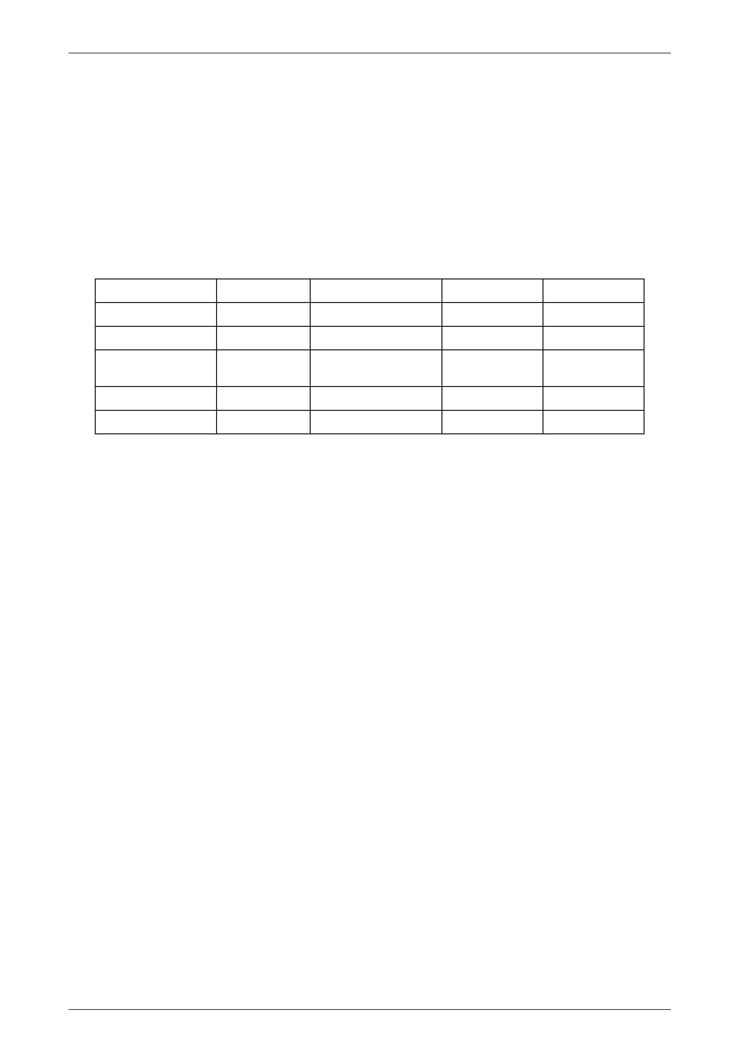
HSV Suspension Systems
MODEL SPORT PERFORMANCE LUXURY PRESTIGE
Senator Sedan S
Senator Signature S
ClubSport/
ClubSport R8 S O
GTS S
Maloo /Maloo R8 S

Suspension Page C–5
Page C–5
2.2 Front Suspension Components
The following components are fitted to front suspension assemblies as indicated:
Sport Suspension
03C-020601 Spring - Frt Susp (Sports)
03F-020601/2 Strut Asm - Frt - LH/RH (Sports)
Luxury Suspension
03C-020601 Spring - Frt Susp (Luxury)
03F-021601/2 Strut Asm - Frt - LH/RH (Luxury)
Performance Suspension
03C-000701 Spring Frt Susp (Perform)
03F-000701/2 Strut Asm Frt - RH/LH (Perform)

Suspension Page C–6
Page C–6
2.3 Service Operations
Service front suspension assemblies fitted to HSV models in accordance with the relevant Holden VY Series Service
Information. Additional service requirements for specific HSV suspension assemblies are detailed in succeeding
paragraphs.
Safety And Cautionary Note For Vehicles
Equipped With ABS.
Whenever any component that forms a part of
the ABS is disturbed, it is vital that the
complete ABS system is checked. Refer to
Section 5B – ABS & ETC of the Holden VY
Service Information.
The tyre life of high performance lo w-profile tyres fitted to HSV VY vehicles is very sensitive to the toe-in setting of the
front suspension. It is crucial therefore, that care is taken to set the toe-in accurately to the correct specification.
The front wheel alignment specification for VY vehicles is:
VY Models
Toe-in
Degrees Total 0°10' ± 0°10'
Degrees Per Wheel 0°05' ± 0°5'
Camber –0°30' ± 0°20'
Caster 7°45' ± 1°15'
The toe-in specification is deliberately quoted as an angle because wherever possible toe-in should be measured in
degrees.
Wheel Ali gnment Machine Calibration
(From Holden Service Bulletin November 1993)
Investigation of front wheel alignment co mplaints has revealed a number of dealers with alignment machines incorrectly
calibrated for the vehicle/s being checked. This situation arises because of two basic conventions for measuring toe-in;
Measured across a 14"rim as if tyre is not fitted, and
Measured across 28" tyre. In reality, few modern tyres have a 28"outside diameter, but this standard was developed
when larger tyres were used.
The 28"standard is a carryover from the days when toe-in was measured by jacking the front wheels off the ground,
spinning them, and scribing a reference line on each tread. After settling the vehicle down, the toe-in could then be
measured directly from the tyres with a ‘trammel bar’. However, some manufacturers specify toe-in as if the trammel bar
was placed at the wheel rim diameter, nominally 14" Setting toe-in using the wrong convention for the wheel alignment
machine will cause the actual toe-in to be either TWICE or HALF as much as the specification.
NOTE
If In Doubt, Set Toe-In Using Degrees, As The
Angle Is Unaffected By The Diameter Of The
Wheels Used.
Suspension Page C–7
Page C–7
How To Check Your Machine
Check with the manufacturer of your equipment if unsure of which standard your machine uses to display toe-in. If
unable to establish this, or if your machine appears to be inaccurate, check the machine as follows:
• Fit properly in flated 15"wheels and tyres to the front of a VP or VR Commodore. Jack the car, spin the wheels and
scribe a line at the middle of each tyre Set the vehicle on the alignment machine and set toe-in to 10mm (5mm per
wheel).
• Measure toe-in at rear of tyres and then at front of tyres with a ‘trammel bar’. If the front distance is less than the
rear distance, you are measuring the toe-in correctly. Compare the measured toe-in to the following table to assess
your machines calibration.
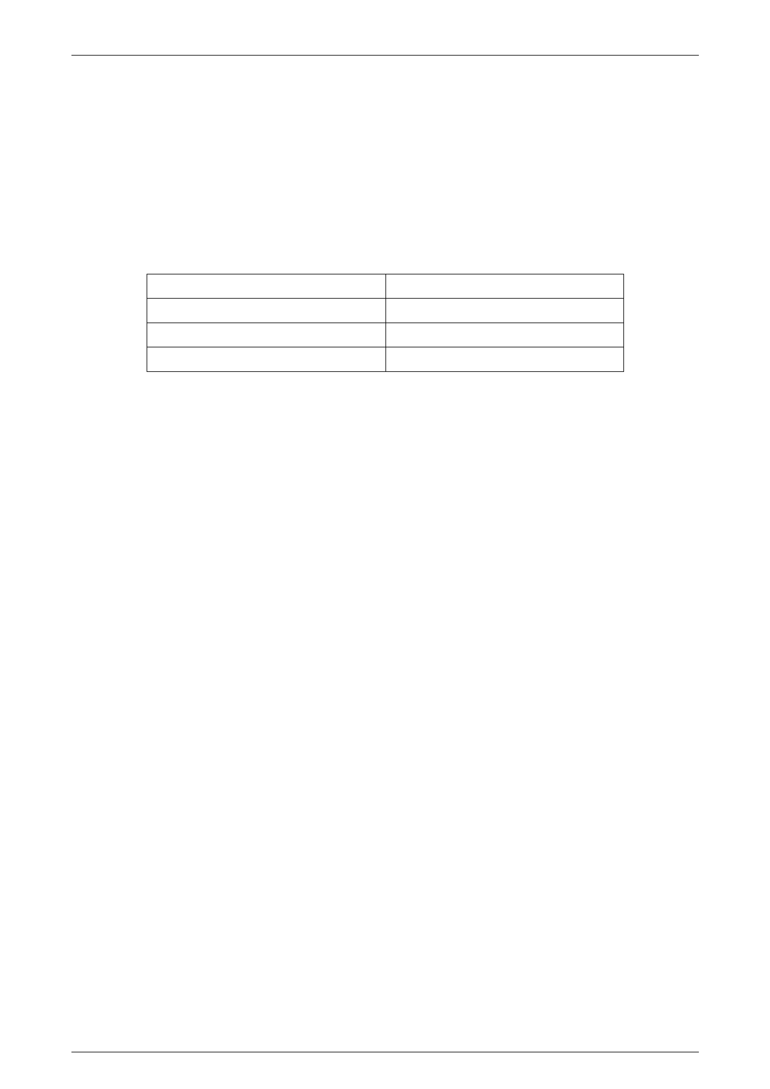
MEASURED TOE-IN RESULT
7 to 11 mm Machine reads @28"
16 to 22 mm Machine reads @ 14"
Other Calibrate Machine
NOTE
The above figures are correct for a 205/65/15
tyre, being a 25"diameter.


Suspension Page C–9
Page C–9
3 Independent Rea r Suspension
3.1 General
Rear suspension assemblies fitted to HSV models are detailed in the 2 Front Suspension, paragraph 1 these
assemblies have been developed to satisfy the various applications of the range of HSV models described in that
paragraph. Non-level ride shock absorbers are gas pressurised, level ride are not.

Suspension Page C–10
Page C–10
3.2 Rear Suspension Components
The following components are fitted to rear suspension assemblies as indicated:
Sport Suspension
Sedan Models
04B-970702 Spring - RR Susp (Sport)
04E-020601 Shock Abs - RR (Sport)
04F-971001 Bar - RR Stabiliser (15mm)
Utility Models
04B-010501 Spring - RR Susp (Sport Utility)
04E-020501 Shock Abs - RR (Sport Utility)
04F-010503 Bar - RR Stabiliser (14mm)
Luxury Suspension
04B-970801 Spring - RR Susp (Sedan)
04E-021601 Shock Abs - RR (Luxury Sedan) Sensatrac
04F-971001 Bar RR Stabiliser (15mm)
Performance Suspension
04B-970702 Spring RR Susp (Sport )
04E-000703 Shock ABS-RR (Perform)
04F-971001 Bar-RR Stabiliser (15mm)
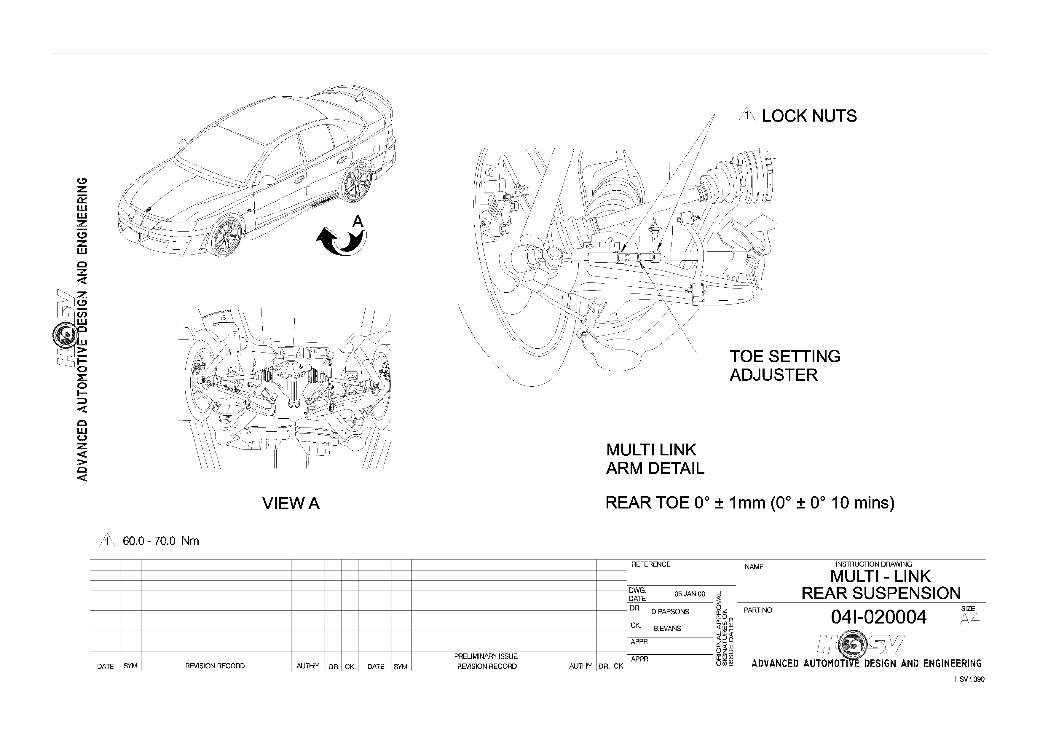
Service Manual Information For Multi Link IRS
Refer: Multi-link Rear Suspension Drawing 04I-020004
Suspension Page C–11
Page C–11

Suspension Page C–12
Page C–12
3.3 Rear Suspension Geometry
The rear suspension is not adj usta ble, but the geometry is se t to:
Camber: –1°00’ ± 0°30’
Total Toe: 0°00’ to ± 0°50’

Suspension Page C–13
Page C–13
4 Rear Suspension – Luxur y
(Incorpor ating Automatic Le vel
Ride)
4.1 General Description
Automatic Level Ride is fitted as standard to Senator, Senator Signature, Grange models. Automatic Level Ride is an
electronically controlled self levelling system that maintains the vehicle at a constant trim height, independent of load.
This feature uses a specifically designed electronic sensor, fixed to the rear cross member on the right hand side (see
Drawing 04I-020005), which controls an electric motor driving a single cylinder air compressor, and an exhaust air
solenoid valve. The compressor supplies the nece ssary pressure to operate the Air Shock Absorbers via "snap on" air
lines. The Air Shock Absorbers assist the rear springs in supporting the vehicle body under all loads.
The sensor has an integrated electronic controller that is programmed to adjust ride he ight only when necessary,
ignoring sudden changes, as experienced on bumpy roads. The design of the system maintains trim at all times provided
the battery is connected. As a safeguard to prevent the battery being flattened, an electronic timer switches off the
compressor if it runs for a prolonged period (i.e. due to an air leak in the system).
The compressor assembly includes a maximum pressure release valve and an air drier. All air entering or exhausting the
system flows through the dryer, which has an internal minimum pressure retention valve preventing the Air Bag,
surrounding each Shock Absorber, from completely exhausting independent of the sensor controlled exhaust valve.
A number of benefits result from the level ride feature. These include headlamp aim and rear view mirror adjustment
being maintained independent of load, as well as ensuring the rear wheel camber and toe-in are held at the optimum
positions to minimise tyre wear. An additional major benefit is obtained from supplementary design changes that can be
made to spring and damper rates for improved ride quality at all loading conditions with minimum compromise to
handling. These changes are possible since the suspension does not have to be sufficiently stiff to absorb road impacts,
while supporting maximum vehicle load.
Electrical power to operate the Level Ride system is supplied by a separate harness except the Senator Signature model
which uses the main integrated wiring harness and a short ‘patch harness.

Suspension Page C–14
Page C–14
4.2 System Operation
Activation
The sensor's actuating arm is attached to the lower control arm via a connecting link (See Drawing 04I-020005). Before
any activation can occur the actuating arm must remain in either the intake or exhaust zone for a continuous 17 to 20
seconds.
The time delay prevents the compressor or exhaust valve from activating when the vehicle encounters sudden bumps.
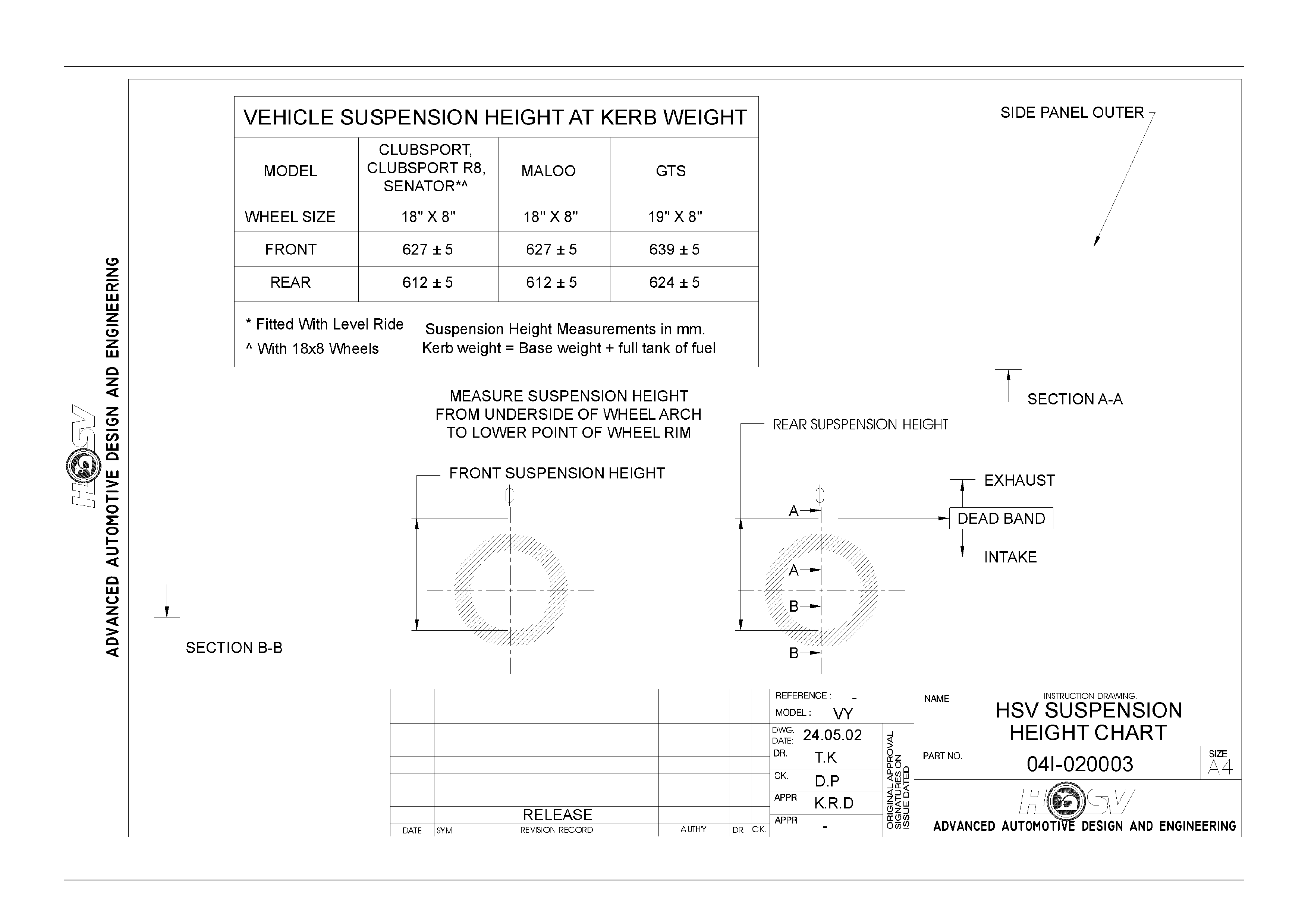
Another stability feature is a designed "Deadband". The Deadband helps to minimise hunting by deactivating the
compressor and solenoid when the vehicle trims into or onto one of the Deadband edges. Refer to Figure C-2 for details
on rear suspension trim heights and Deadband.
Loaded Vehicle
When the vehicle is loaded, the vehicle body moves downward into the intake zone, causing the actuating arm to move
upwards. After 17 to 20 seconds, the sensor relieves compressor head pressure by briefly activating the compressor
relay. The compressor starts and pressurises the air shock absorbers until the vehicle body aligns with the bottom edge
of the Deadband, at which point the compressor stops.
Unloaded Vehicle
When the vehicle is unloaded, the vehicle body moves upward into the exhaust zone, causing the actuating arm to move
downwards. After 17 to 20 seconds, the sensor activates the exhaust relay. The exhaust solenoid activates and vents
pressure from the air shock absorbers until the vehicle body aligns with the top edge of the Deadband, at which point the
solenoid deactivates.
Deactivation
The compressor and exhaust solenoid operations are monitored and controlled by individual but interconnected timers.
The timers deactivate specific trimming operations under the following conditions:
a. If the compressor runs for a cumulative time of more than four-and-a-half minutes, the compressor timer
deactivates all system operations.
b. If the exhaust solenoid is active for a cumulative time of more than four-and-a-half minutes, the solenoid timer
deacti v ates the sole noid.
NOTE
The sensor timers must be reset before any
further operation can take place. The VY system
is reset after each ignition cycle ON, OFF for one
minute, ON.
Suspension Page C–15
Page C–15

Suspension Page C–16
Page C–16
4.3 Maintenance
Service
Do Not Lower Car With Empty Shock Absorber
Air Bags As Damage May Result.
This system is designed to run with the minimum of maintenance. At every service the following components should be
checked:
a. Air Lines: Inspect lines and replace if sleeving or line is worn. Refer Air Line And Air Filter - Service for service
instructions.
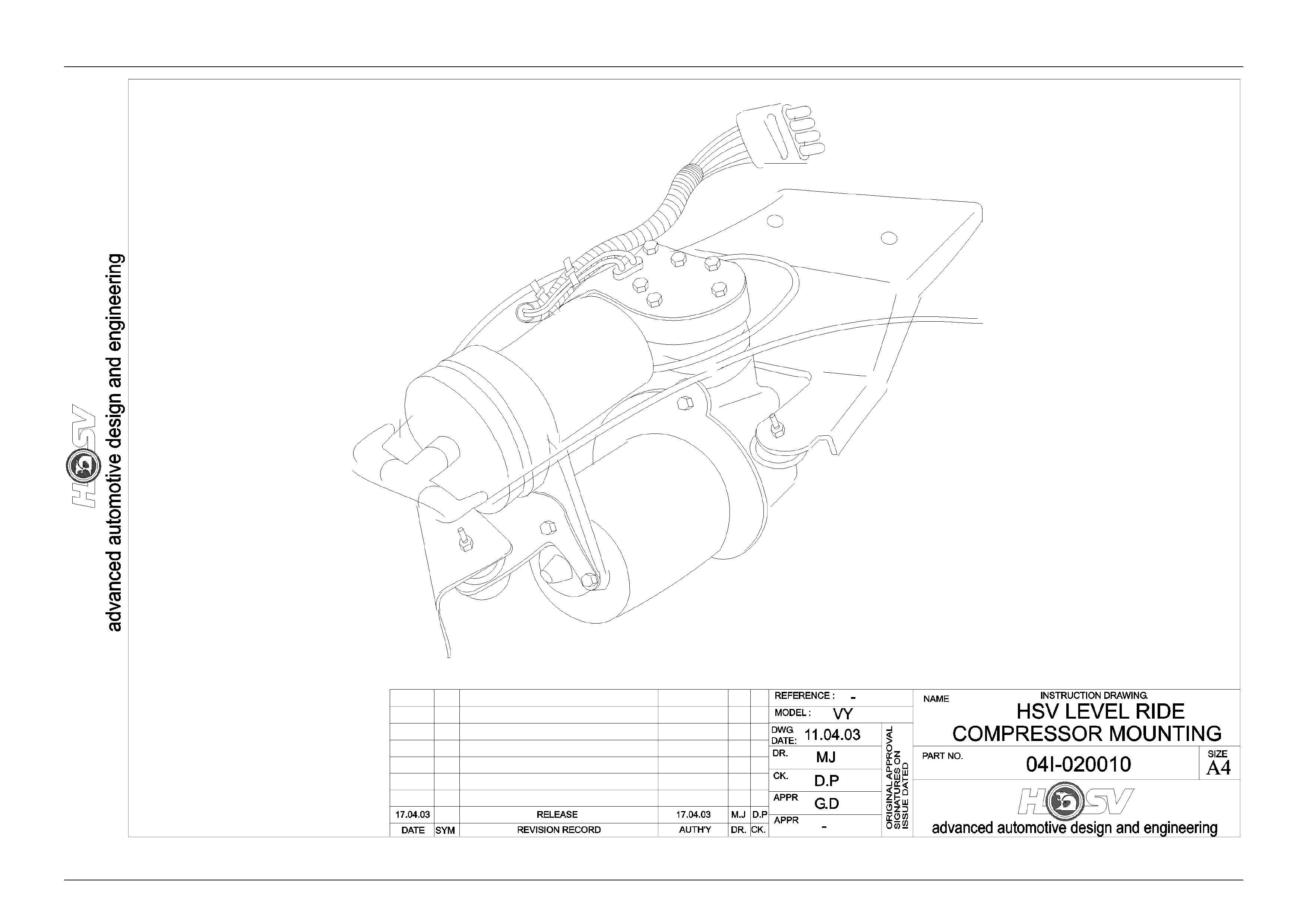
b. Harness Ties: Check harness ties and replace if broken or loose, refer Drawings 04I-020005 and 04I-020010.
c. Compressor Mounts. Check compressor mounts and replace if broken. Check security of mounts.
d. Air Filter. Inspect and replace air filter if contaminated or at the 30,000km, 70,000km and subsequent 40,000km service
intervals, whichever comes first. Follow instructions in Air Line And Air Filter - Service for replacement details.
NOTE
The Air Filter is the only regular service item.
Contents of Automatic Leve l Ri de System
VY Level Ride System
PART NO DESCRIPTION
04E-970807 HEIGHT SENSOR-ASM
04E-970802 BRACKET HEIGHT SENSOR
70B-050001 NUT NYLOC
73A-082088 BOLT (HT SNSR BRKT TO XMBR)
70G-080002 NUTSERT
04E-970803 BRACKET BALL STUD
04E-970809 LINK HEIGHT SENSOR SED, LUX 70mm
04E-971002 LINK HEIGHT SENSOR W AG, LUX 77mm
04E-211917 COMPRESSOR
04E-970805 BRACKET COMP TO BODY
73A-053088 BOLT (COMPRESSOR TO BRKT)
72H-970801 BOLT (COMP BRKT TO BODY)
04E-211913 T PIECE
04E-211914 AIR FILTER
75C-180501 CABLE TIE
04E-970806 AIRLINE ASM-COMP TO SHOCK ABSORBER
12H-970801 LEVEL RIDE PATCH HARNESS
12H-970803 LEVEL RIDE UNDERBODY

Suspension Page C–17
Page C–17
Compressor Assembl y - Service
The compressor assembly is located above the left hand rear axle shaft and below the floor pan. The VY system is secured
to a compressor bracket which then mounts to the chassis subframe. The general arrangement for VY Compress or
Assembly is shown in Drawing 04I-020010.
Removal
Remove the air filter, remove the three screws securing the compressor to the compressor mounting bracket and remove
compressor as sem bly .
Suspension Page C–18
Page C–18
Suspension Page C–19
Page C–19
Suspension Page C–20
Page C–20
Air Line And Air Filter - Service
Air Line
Removal
Disconnect snap-on air lines by rotating each clip 90° and gently pulling the line free. Cut or unclip air line ties.
Installation
Reverse the above procedure taking care not to kink lines when installing to shock absorber. Ensure air lines do not
contact she et meta l raw edges .
NOTE
Ensure That Air Line Ties Are Correctly
Positioned And That Air Lines Are Secure.
Air Filter
Removal
Remove compressor assembly as per instructions Compressor Assembly - Service. Unclip filter from compressor
isolation bracket and twist free from air hose.
Installation
Secure new filter to bracket and connect hose.
Shock Absorber - Service
The shock absorbers are serviced as per the standard Holden rear shock absorbers. Refer Section 4A, 2.10 Rear Shock
Absorbers And/Or Bushing in the MY 2003 VY Series and V2 Series Service Information.
Do Not Lower Car With Empty Air Bags As
Damage May Result. Whenever The System Is
Unpressurised Or When The Vehicle Rear Sits
Obviously High After Lowering From An On-
Hoist Operation (Suggesting Shock Absorber
Air Bags May Be Pinched Or Jammed),
Immediately Raise Vehicle, Disconnect
Sensor Connecting Link, Push Sensor Arm
Above Horizontal For 17 To 20 Seconds, And
Run Compressor For About 30 Seconds To
Inflate Shock Absorbers. Reconnect Sensor
Connecting Link And Lower Vehicle. Driving
The Vehicle With Pinched Or Jammed Shock
Absorber Air Bags Will Irrepairably Damage
The Shock Absorber

Suspension Page C–21
Page C–21
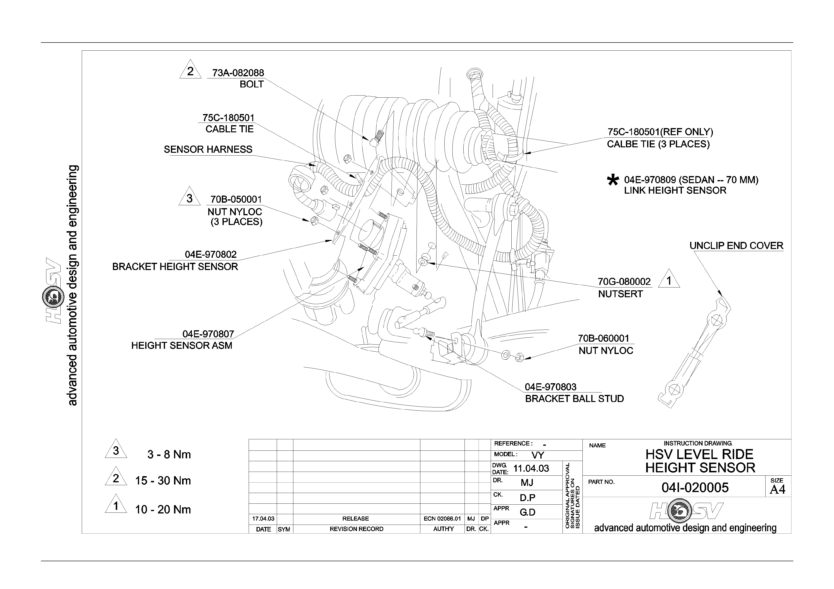
Height Sensor - Service
The height sensor assembly is bolted to the rear crossmember on the right hand side as illustrated in Drawing
04I-020005. The sensor bracket specification is critical and essential that the brac ket is not bent or distorted.
Read the installation procedure carefully before fixing the bracket to the crossmember.
Removal
a. Unclip or cut cable ties as appropriate which support sensor harness to the height sensor bracket. Separate the
harness from the sensor gently squeezing and pulling away the connector retainer. Refer Drawing 04I-020005.
b. Remove height sensor link by unclipping link end cover and gently prying from sensor arm. Refer Drawing
04I-020005 for link details.
c. Support sensor while removing sensor bracket bolt (73A-082088). Refer Drawing 04I-020005.
Installation:
Before proceeding any further, check that the sensor bracket is within specification as detailed in Level Ride
Specifications. Reverse the above procedure, taking care not to bend or distort the bracket. Ensure link clip is
refastened otherwise, system failure may occur.
Relay Control Module - Service
VY relays are incorporated in the Relay Box in the driver’s-side lower dash panel.
Diagnostics
General
The following procedures are guides that can help to determine the probable cause of an Automatic Levelling System
problem.
It is important that the reader is familiar with section 4.2 System Operation, in order to accurately identify the problem.
Test Equipment Required
• DC Voltmeter and Ohmmeter (>20 megohm/ v).
• Jumper leads required for short circuit (cct.) tests.
Level Ride Specificati ons
The rear suspension height specifications are shown on Drawing 04I-020003.
To achieve this specification note the following:
1. The vehicle must be at kerb weight, see Drawing 04I-020003.
2. The internal angle of the Height Sensor Bracket is 80 degrees.
Suspension Page C–22
Page C–22
Suspension Page C–23
Page C–23
Suspension Page C–24
Page C–24

Suspension Page C–25
Page C–25
4.4 Service Operations
Service Operations and Service Intervals for HSV Rear Suspension assemblies are the same as those detailed in the
relevant Holden VY Service Information except when detailed otherwise in this supplement. Refer to Section 4A Rear
Suspension in the MY 2003 VY and V2 Series Service Information
The Height Sensor Link part number and length for each Level Ride application is as follows:
• 04E-970809 (VY SEDAN - 70mm)
For rear wheel alignment specification, refer to Section 4A Rear Suspension. Fo r trim height specific ations refer to
Drawing 04I-020003.
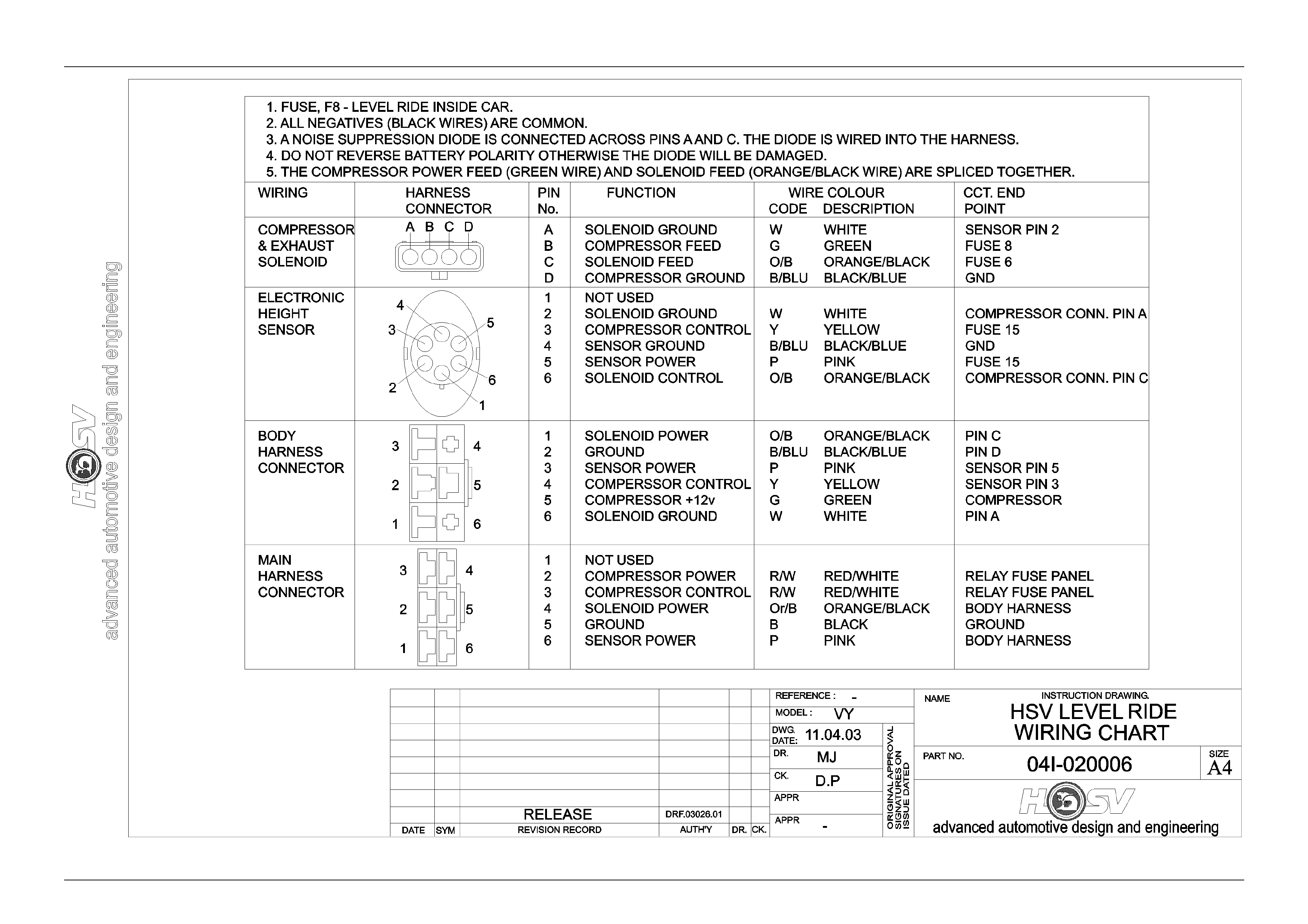
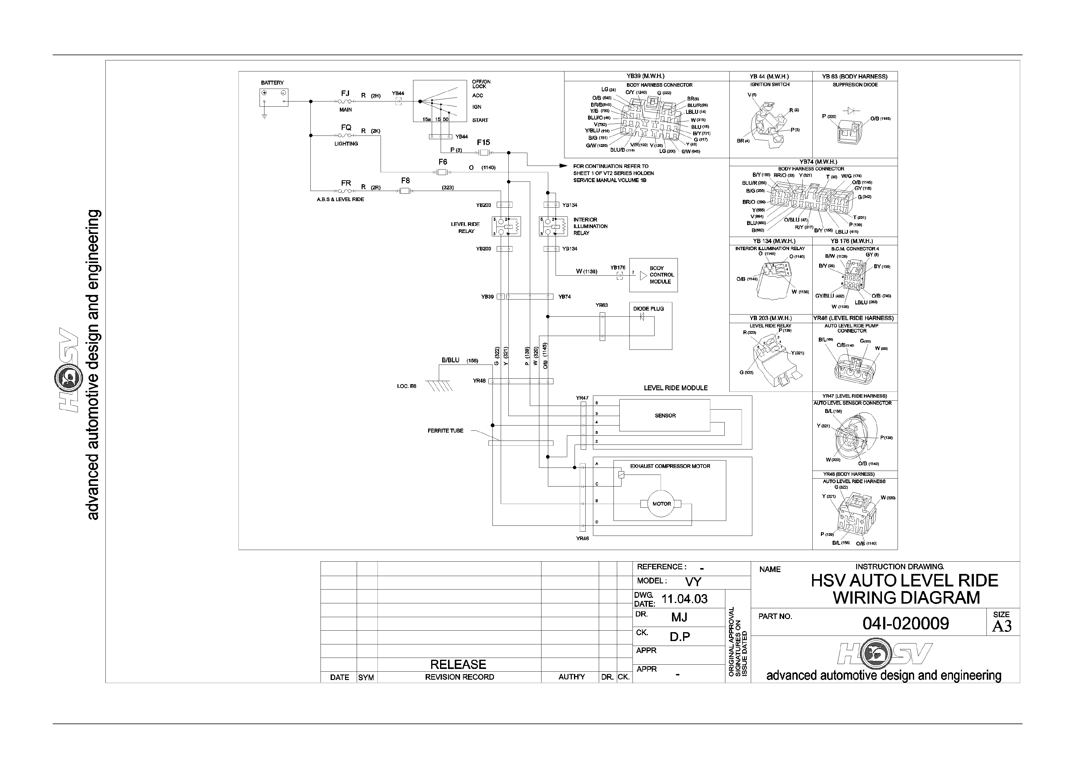
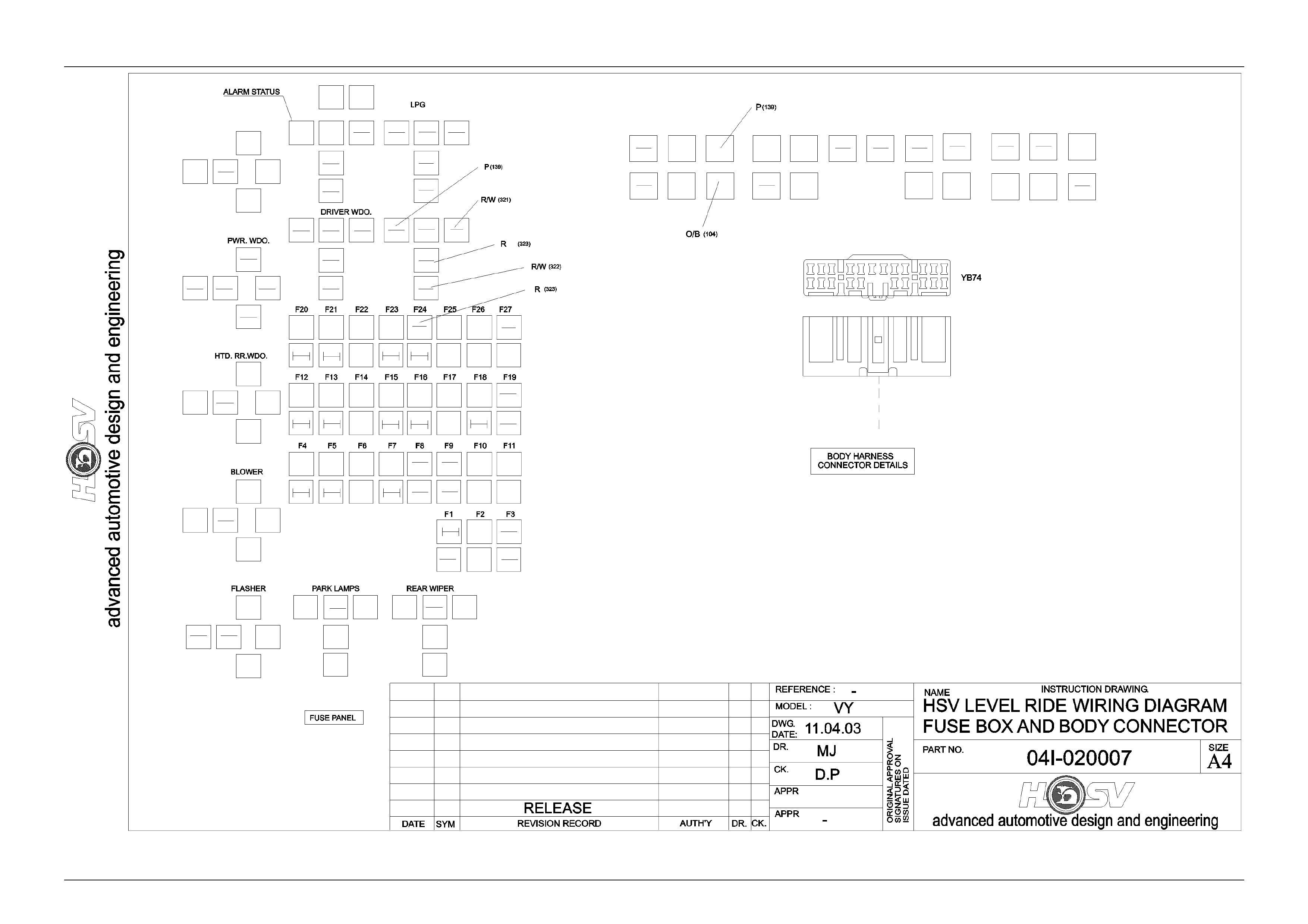
Wiring connections for the VY system are shown in Section 12N Fuses, Relays and Wiring Harnesses or
Section 12P Wiring Diagrams.

Suspension Page C–26
Page C–26
4.5 Diagnostics
The following procedures are guides that can help determine the cause of problems with the level ride system. It is
important that the user of these procedures has a working knowledge of the level ride system.
Suspension Page C–27
Page C–27
Preliminary Diagnostic Procedure
Step Action Value Yes No
1. Does vehicle trim? Go to Step 2 Go to Step 3
2. Does vehicle trim to correct height? Refer to Drawing
04I-020003
Specifications
System OK Check all rear
suspension
components for
wear and
damage, paying
particular
attention to the
height sensor
mounting and
bracket
3. Does vehicle lower after specified time when
vehicle is unloaded? 20 seconds Go to Step 4 Go to Chart,
Compressor
Assembly Test
(Solenoid Test)
4. Does vehicle rise after specified time when
vehicle is loaded? 20 seconds System OK Go to chart
Compressor
Assembly Test
(Motor Test)
Compressor Assembly Test (Solenoid Test)
Step Action Value Yes No
1. Has a system reset been carried out by
cycling ignition, refer 4.3 Maintenance -
Diagnostics in this Section?
Go to Step 2 Carry out system
reset and re-
check sy ste m
2. Is fuse 8 OK (25 amp fuse .) ?
Is fuse 6 OK ( 10 amp fuse in fuse panel) ?
Is fuse 15 OK (10 amp fuse in fuse panel) ?
Go to Step 3 Replace blown
fuse/s, che ck
wiring for cause
of fuse/s blowing
and re-check
system
3. Disconnect the wiring harness at the level
ride sensor
Turn ignition ON
Short circuit pin 2 (white wire) to pin 4 (Black
wire) in the level ride sensor connector
(connector YR47)
Listen for clicking of the solenoid valve and
the air escaping from the system, or check
for voltage between pin A & C at the
compressor harness connector (connector
YR46).
Is there a clicking sound from solenoid valve,
escaping air from the system or voltage at
the compressor harness connector between
pin A (Orange/Black) wire & C (white wire)?
Compressor asm
solenoid OK,
proceed to Chart
Height Sensor
Test (Solenoid
Operation) in this
Section
Go to Step 4
4. Check system wiring for continuity
Is wiring OK?
Replace
compressor
assembly refer
Compressor
Assembly -
Service
Test system with
other harnesses-
replace as
necessary.

Suspension Page C–28
Page C–28
Compressor Assembly Test (Compressor Motor Test)
Step Action Value Yes No
1. Has a system reset been carried out by
cycling ignition, refer Deactivation Note in
this Section?
Go to Step 2 Carry out system
reset and re-
check sy ste m
2. Is fuse 8 OK (25 amp fuse.) ?
Is fuse 6 OK ( 10 amp fuse in fuse panel) ?
Is fuse 15 OK (10 amp fuse in fuse panel) ?
Go to Step 3 Replace blown
fuse/s, che ck
wiring for cause
of fuse/s blowing
and re-check
system
3. Disconnect the wiring harness at the level
ride sensor
Turn ignition ON
Short circuit pin 3 (yellow wire) to pin 4
(Black wire) in the level ride sensor
connector (connector YR47)
Listen for compressor motor running, or
check for vo ltage between pin B (Green wi re)
& D (Black wire) at the compressor harness
connector (connector YR46).
Does the compressor motor run or is there a
voltage at the compressor harness connector
between pin B & D?
Compressor
motor OK,
proceed to Chart
Height Sensor
Test Comp ressor
Operation
in this Section
Go to Step 4
4. Check system wiring for continuity
Is wiring OK?
Replace
compressor
assembly refer
Compressor
Assembly -
Service
Replace patch
harness and re-
check sy ste m
Height Sensor Test (Solenoid Operation)
Step Action Value Yes No
1. Has a system reset been carried out by
cycling ignition, refer Deactivation? Go to Step 2 Carry out system
reset and re-
check sy ste m
2. Disconnect height sensor link, refer Height
Sensor- Service, in this Section
Turn ignition ON
Lower height sensor arm 45° and wait 20
seconds
Listen for clicking of the solenoid valve and
the air escaping from the system, or check
for voltage between pin A (White wire) & C
(Orange/Black wire) at the compressor
harness connec tor ( conn ect or Y R 46)
Is there a clicking sound from solenoid valve,
escaping air from the system or voltage at
the compressor harness connector between
pin A & C?
12 volts
System OK.
(re-check system
for correct
operation if
necessary)
Go to Step 3
3. Check system wiring for continuity
Is wiring OK?
Replace height
se nsor assembly
refer Height
Sensor- Service,
in this Section
and re-check
system
Replace patch
harness and re-
check sy ste m

Suspension Page C–29
Page C–29
Height Sensor Test (Compressor Operation)
Step Action Value Yes No
1. Has a system reset been carried out by
cycling ignition, refer Deactivation- Note in
this section?
Go to Step 2 Carry out system
reset and recheck
system
2. Disconnect height sensor link, refer
Height Sensor- Service, in this Section
Turn ignition ON
Raise height sen sor arm 45° and wait 20
seconds
Listen for compressor motor running or check
for voltage between pin B (Green wire) & D
(Black wire) at the compressor harness
connector (connector YR46)
Does the compressor motor run or is there a
voltage at the compressor harness connector
between pin B & D?
12 volts
Go to Step 3 Go to Step 5
3 The compressor motor may be operating but
the compressor may have failed
Run the motor for two minutes and check the
shock absorber air bag s are being
pressurised
Are air bags being pressurised?
System OK (re-
check sy ste m
for correct
operation if
necessary)
Go to Step 4
4. Check air compressor filter for blockage, refer
Air Filter, in this Section
Is filter OK?
Replace
compressor
assembly and
re-check system
Replace filter and
re-check system
5. Check system wiring for continuity.
Is wiring OK?
Replace height
sensor
assembly refer
Height Sensor,
in this Section
and re-check
system
Replace harnes s
and re-check
system

Suspension Page C–30
Page C–30
5 Rear Axle
5.1 General
HSV VY models are equipped with either a Limited Slip Differential or Hydratrak (a specifically designed Viscous
coupling type limited slip differential).
• Manual transmission LS1 vehicles final drive ratio is 3.73:1 and the differential (Part No.92082622) can be
identified by Broadcast Code ET.
• Manual transmission VY GTS vehicles final drive ratio is 3.91:1 and the differential (Part No. 92089748) can be
identified by Broadcast Code CK.
• Automatic transmission LS1 vehicles final drive ratio is 3.07:1 and the differential (Part No. 9205342) can be
identified by Broadcast Code EH.
• Automatic transmission VY GTS vehicles final drive ration 3.46:1 and the differential (Part No. 92085135) can be
identified by Broadcast Code FP.
Suspension Page C–31
Page C–31
5.2 Service Operations
The differential oil must be changed at 45,000 km intervals. Use synthetic hypoid gear oil to HN2040 such as ‘Mobilube
SHC 80W-140 ID’.
The viscous coupling cartridge assembly is a sealed unit and must be replaced as a complete assembly if required.
General service operations are the same as those described in the Holden VS series Service Manual however, to
determine if the Hydratrak coupling cartridge is faulty, undertake the following torque check. The Hydratrak rear axle
assembly is covered by the current Axle Warranty Changeover agreement between GMHAL and BTR Engineering (refer
GMHA Dealer Bulletins).
Torque Check
i. Place transmission in neutral with engine turned 'OFF'.
ii. Jack up one rear wheel, then release park brake lever to fully 'OFF' position. Support vehicle body on a safety
stand.
iii. Remove centre cap (alloy wheels).
iv. Mark relationship of road wheel to axle flange. Remove road wheel attaching nuts and remove wheel.
v. Remove caliper attaching bolts and remove caliper from mounting, refer Section 5 Brakes in the MY 2003 VY and
V2 Series Service Information. Remove brake disc.
Do Not Allow Caliper To Hang By Brake Hose.
vi. Using a torque wrench in conjunction with adaptor, Tool No. 4A48, and torque wrench adaptor E6662B, rotate axle
shaft in forward direction. If the unit is operating satisfactorily, a torque reading of 35 N.m should be obtained whilst
turning the axle shaft at 20 rpm (e.g. one third of a turn per second).
If a torque reading of less than 25 N.m or more than 80 N.m (@ 20 rpm) is obtained, remove differential case and
inspect the differential components and repair or replace as necessary.
However, if the Hydratrak Coupling cartridge unit is faulty it will require replacement with a new Coupling unit, as it
is a sealed, non-serviceable fluid filled component.
Do Not Attempt To Repair Or Weld The
Coupling Unit.
vii. Install brake disc and caliper. Tighten caliper attaching bolts to the correct torque specification.
NOTE
Caliper Attaching Bolt Torque Specification Is
55- 70 N.m
viii. Install road wheel.
NOTE
When installing the wheel, align the marks made
prior to removal.
ix. Remove safety stand and lower vehicle.
x. Tighten road wheel attaching nuts to the correct torque specification.
NOTE
Torque Specific ation Is 100-125 N.m
xi. Refit wheel cover/centre cap.

Suspension Page C–32
Page C–32
6 Limited Slip Differential
From Holden Commodore VS Series Service Information
When servicing a vehicle fitted with a Limited
Slip Differential (including Hydratrack type),
never run the engine with the transmission in
gear and one wheel raised. The driving force
to the wheel on the ground may cause the
vehicle to move.
NOTE
'On Car' type wheel balancers are not
recommended for use on the rear wheels of cars
equipped with a Limited Slip Differential. One rear
wheel will drive if in contact with the ground when
the opposite wheel is raised. This type of
balancer may be used by removing the wheel
opposite to the one being balanced with the
vehicle raised and supported on safety stands.
(Refit wheel nu ts, reversed, to retain brake disc).

Suspension Page C–33
Page C–33
7 Propeller Shaft And Universal
Joints
All other HSV models use standard GMHA propeller and drive shafts.
7.1 Service Operations
Service procedures for propeller shaft assemblies fitted to HSV models are the same as those described in Section 4C -
Propeller Shaft And Universal Joints in the MY 2003 VY and V2 Series Service Information.