
Suspension Page C-1
Page C-1
Section C
Suspension
ATTENTION
HSV vehicles are equipped with a Supplemental Restraint System (SRS). An SRS consists of seat belt pre-
tensioners (fitted to all front seats), a driver’s-side air bag, a passenger’s-side air b ag and left and right hand
side air bags. Refer to CAUTIONS, Section 12M, in Volume 12 of the Holden VYII series Service Manual before
performing any service operation on or around SRS components, the steering mechanism or wiring. Failure
to follow the CAUTIONS could result in personal injury or unnecessary SRS system repairs.
1 Purpose...............................................................................................................................................C-3
2 Front Suspension...............................................................................................................................C-4
2.1 General ................................................................................................................................................................C-4
HSV Suspension Systems..................................................................................................................................C-4
2.2 Front Suspension Components.........................................................................................................................C-5
2.3 Service Operations .............................................................................................................................................C-6
Wheel Alignment Machine Calibration..............................................................................................................C-6
How To Check Your Machine.............................................................................................................................C-7
2.4 Service Intervals..................................................................................................................................................C-8
3 Independent Rear Suspension .........................................................................................................C-9
3.1 General ................................................................................................................................................................C-9
3.2 Rear Suspension Components........................................................................................................................C-10
3.3 Rear Suspension Geometry.............................................................................................................................C-12
4 Rear Suspension – Luxury (Incorporating Automatic Lev el Ride).............................................C-13
4.1 General Description..........................................................................................................................................C-13
4.2 System Operation .............................................................................................................................................C-14
Activation...........................................................................................................................................................C-14
Loaded Vehicle .................................................................................................................................................C-14
Unloaded Vehicle .............................................................................................................................................C-14
Deactivation.......................................................................................................................................................C-14
Contents of Automatic Level Ride System.....................................................................................................C-16
Air Line And Air Filter - Service .......................................................................................................................C-18
Shock Absorber - Service ...............................................................................................................................C-18
Height Sensor - Service ...................................................................................................................................C-18
Relay Control Module – Service .....................................................................................................................C-18
Diagnostics .......................................................................................................................................................C-18
General ........................................................................................................................................................C-18
Level Ride Specifications ..............................................................................................................................C-18
4.3 Service Operations ...........................................................................................................................................C-20

Suspension Page C-2
Page C-2
5 Rear Axle............................................................................................................................................C21
5.1 General ..............................................................................................................................................................C-21
5.2 Service Operations ...........................................................................................................................................C-22
Torque Check....................................................................................................................................................C-22
6 Limited Slip Differential...................................................................................................................C-24
7 Propeller Shaft And Universal Joints.............................................................................................C-25
7.1 Service Operations ...........................................................................................................................................C-25
Suspension Page C-3
Page C-3
1 Purpose
The purpose of this section is to provide information on the front and rear suspension assemblies fitted to HSV VYII
models. The information is designed to supplement the information contained in the Holden VYII Service Manuals, and
details are given where differences occur between the HSV models and standard Holden models. A series of instruction
drawings describe the design changes and indicate specific part numbers, fitting instructions and relevant notes for
vehicle servicing.
NOTE
If specific technical data on a HSV model is not
contained in this supplement, obtain data for that
model from the relevant Holden VYII series
Service Information Supplement. References are
made throughout this section to Holden Service
Manuals, to assist in providing information for
specific service operations.
When hoisting (or jacking) HSV models,
ensure that the liftin g head of the hoist lifts on
the chassis before the arm of the hoist
contacts the side-skirt
Suspension Page C-4
Page C-4
2 Front Suspension
2.1 General
The front suspension assembly fitted to all HSV VYII models is based on the Holden ‘MacPherson Strut’ design. All HSV
front suspension struts are gas pressurised and Luxury and Grange struts have Monroe Sensatrac. This basic assembly
(and the rear assembly) is then modified by HSV to provide a suspension system more suited to the requirements of the
HSV vehicle. That is, Performance and Sport suspension systems are fitted to sport and performance type vehicles, and
Luxury suspension systems satisfy the requirements of the luxury sedans. A summary of these suspension systems and
their Standard (S) and Optional (O) applications is contained in the following paragraphs:
HSV Suspension Systems
MODEL: SPORT PERFORMANCE LUXURY
Senator Sedan S
Senator Signature S
ClubSport/ S O
ClubSport R8 O S
GTS S
Maloo/Maloo R8 S

Suspension Page C-5
Page C-5
2.2 Front Suspension Components
The following components are fitted to front suspension assemblies as indicated:
Sport Suspension
03C-020601 Spring - Frt Susp (Sports)
03F-030601/2 Strut Asm - Frt - LH/RH (Sports, Red)
Luxury Suspension
03C-020601 Spring - Frt Susp (Luxury)
03F-031601/2 Strut Asm - Frt - LH/RH (Luxury,Red)
Performance Suspension
03C-020601 Spring Frt Susp (Perform)
03F-030701/2 Strut Asm Frt - RH/LH (Performance,Red)
Suspension Page C-6
Page C-6
2.3 Service Operations
Service front suspension assemblies fitted to HSV models in accordance with the relevant Holden VYII Series Service
Information. Additional service requirements for specific HSV suspension assemblies are detailed in succeeding
paragraphs.
SAFETY AND CAUTIONARY NOTE FOR
VEHICLES EQUIPPED WITH ABS
Whenever any component that forms a part of
the ABS is disturbed, it is vital that the
complete ABS system is checked. Refer to
Section 5B – ABS & ETC of the Holden VYII
Service Information.
The tyre life of high performance low-profile tyres fitted to HSV VYII vehicles is very sensitive to the toe-in setting of the
front suspension. It is crucial therefore, that care is taken to set the toe-in accurately to the correct specification.
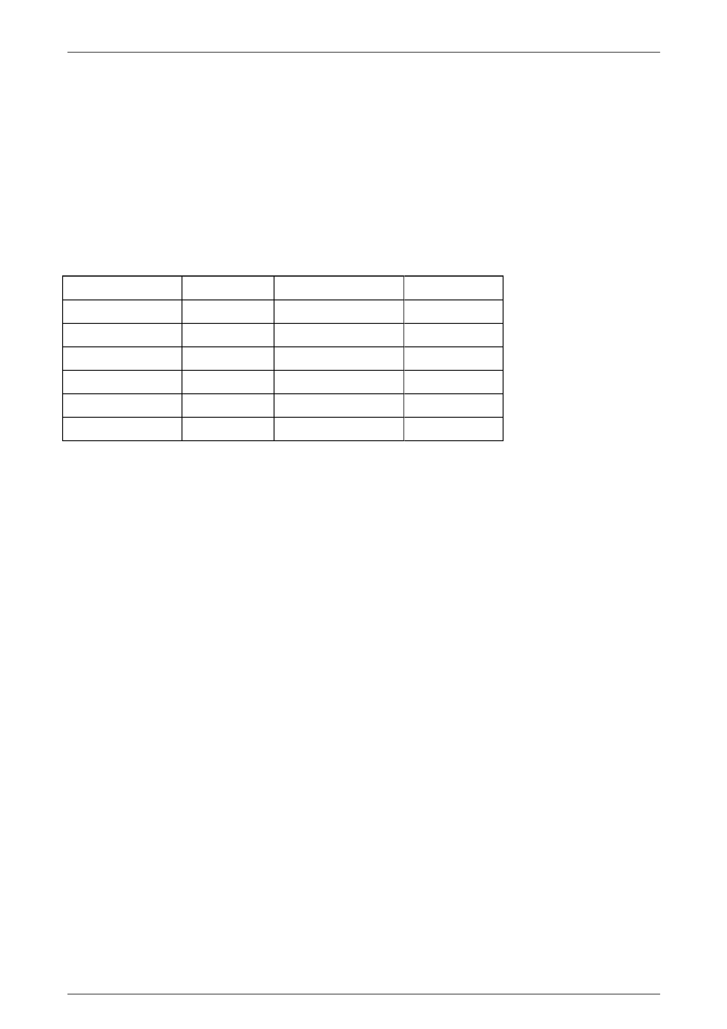
The front wheel alignment specification for VYII vehicles is:
VYII
Toe-in
Degrees Total 0°10' ± 0°10'
Degrees Per Wheel 0°05' ± 0°5'
Camber -0°30' ± 0°20'
Caster 7°45' ± 1°15'
The toe-in specification is deliberately quoted as an angle because wherever possible toe-in should be measured in
degrees.
Wheel Alignment Machine Calibration
(From Holden Service Bulletin November 1993)
Investigation of front wheel alignment complaints has revealed a number of dealers with alignment machines incorrectly
calibrated for the vehicle/s being checked. This situation arises because of two basic conventions for measuring toe-in;
Measured across a 14"rim as if tyre is not fitted, and
Measured across 28" tyre. In reality, few modern tyres have a 28"outside diameter, but this standard was developed
when larger tyres were used.
The 28"standard is a carryover from the days when toe-in was measured by jacking the front wheels off the ground,
spinning them, and scribing a reference line on each tread. After settling the vehicle down, the toe-in could then be
measured directly from the tyres with a ‘trammel bar’. However, some manufacturers specify toe-in as if the trammel bar
was placed at the wheel rim diameter, nominally 14" Setting toe-in using the wrong convention for the wheel alignment
machine will cause the actual toe-in to be either TWICE or HALF as much as the specification.
NOTE
IF IN DOUBT, SET TOE-IN USING DEGREES,
AS THE ANGLE IS UNAFFECTED BY THE
DIAMETER OF THE WHEELS USED.
Suspension Page C-7
Page C-7
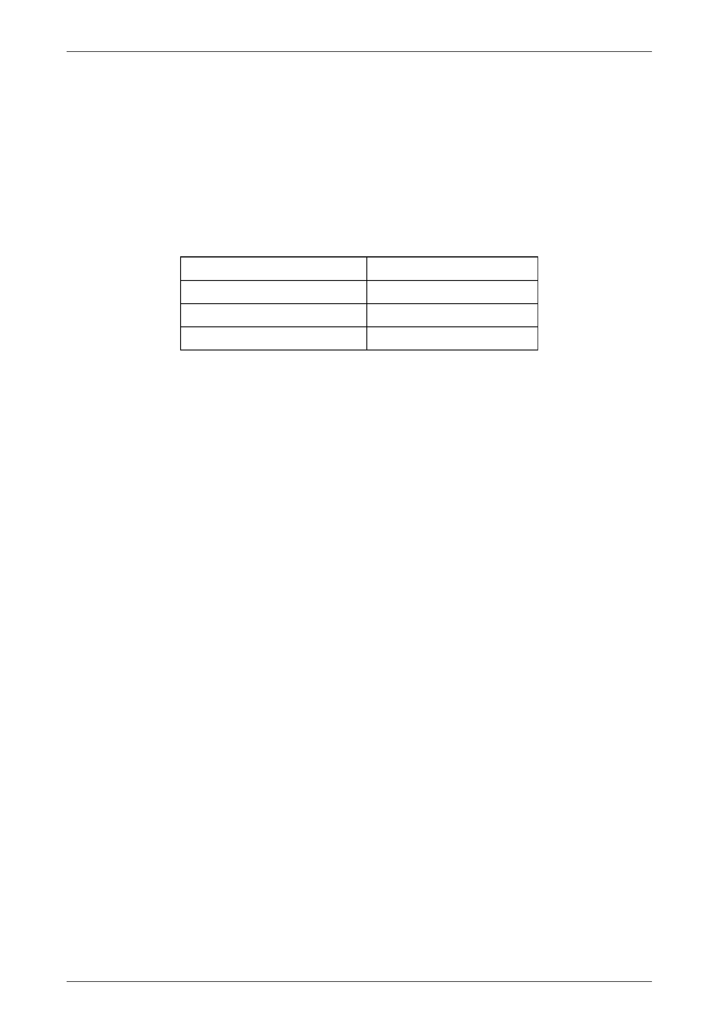
How To Check Your Machine
Check with the manufacturer of your equipment if unsure of which standard your machine uses to display toe-in. If
unable to establish this, or if your machine appears to be inaccurate, check the machine as follows:4
• Fit properly inflated 15"wheels and tyres to the front of a VP or VR Commodore. Jack the car, spin the wheels and
scribe a line at the middle of each tyre Set the vehicle on the alignment machine and set toe-in to 10mm (5mm per
wheel).
• Measure toe-in at rear of tyres and then at front of tyres with a ‘trammel bar’. If the front distance is less than the
rear distance, you are measuring the toe-in correctly. Compare the measured toe-in to the following table to assess
your machines calibration.
MEASURED TOE-IN RESULT
7 to 11 mm Machine reads @28"
16 to 22 mm Machine reads @ 14"
OTHER CALIBRATE MACHINE
NOTE
The above figures are correct for a 205/65/15
tyre, being a 25"diameter.


Suspension Page C-9
Page C-9
3 Independent Rear Suspension
3.1 General
Rear suspension assemblies fitted to HSV models are detailed in the 2 Front Suspension, paragraph 1: these assemblies
have been developed to satisfy the various applications of the range of HSV models described in that paragraph. Non
level ride shock absorbers are gas pressurised, level ride are not.
Rear suspension components fitted to HSV vehicles are similar to Holden VYII and details are given where differences
occur. A series of instruction drawings describe design changes and indicate specific part numbers, fitting instructions
and relevant notes for servicing.

Suspension Page C-10
Page C-10
3.2 Rear Suspension Components
The following components are fitted to rear suspension assemblies as indicated:
Sport Suspension
SEDAN MODELS
04B-970702 Spring - RR Susp (Sport)
04E-020601 Shock Abs - RR (Sport)
04F-971001 Bar - RR Stabiliser (15mm)
UTILITY MODELS
04B-010501 Spring - RR Susp (Sport Utility)
04E-030501 Shock Abs - RR (Sport Utility)
04F-010501 Bar - RR Stabiliser (14mm)
Luxury Suspension
04B-970801 Spring - RR Susp (Sedan)
04E-031601 Shock Abs - RR (Luxury Sedan) Sensatrac
04F-971001 Bar RR Stabiliser (15mm)
Performance Suspension
04B-970702 Spring RR Susp (Sport )
04E-030703 Shock ABS-RR (Perform)
04F-971001 Bar-RR Stabiliser (15mm)
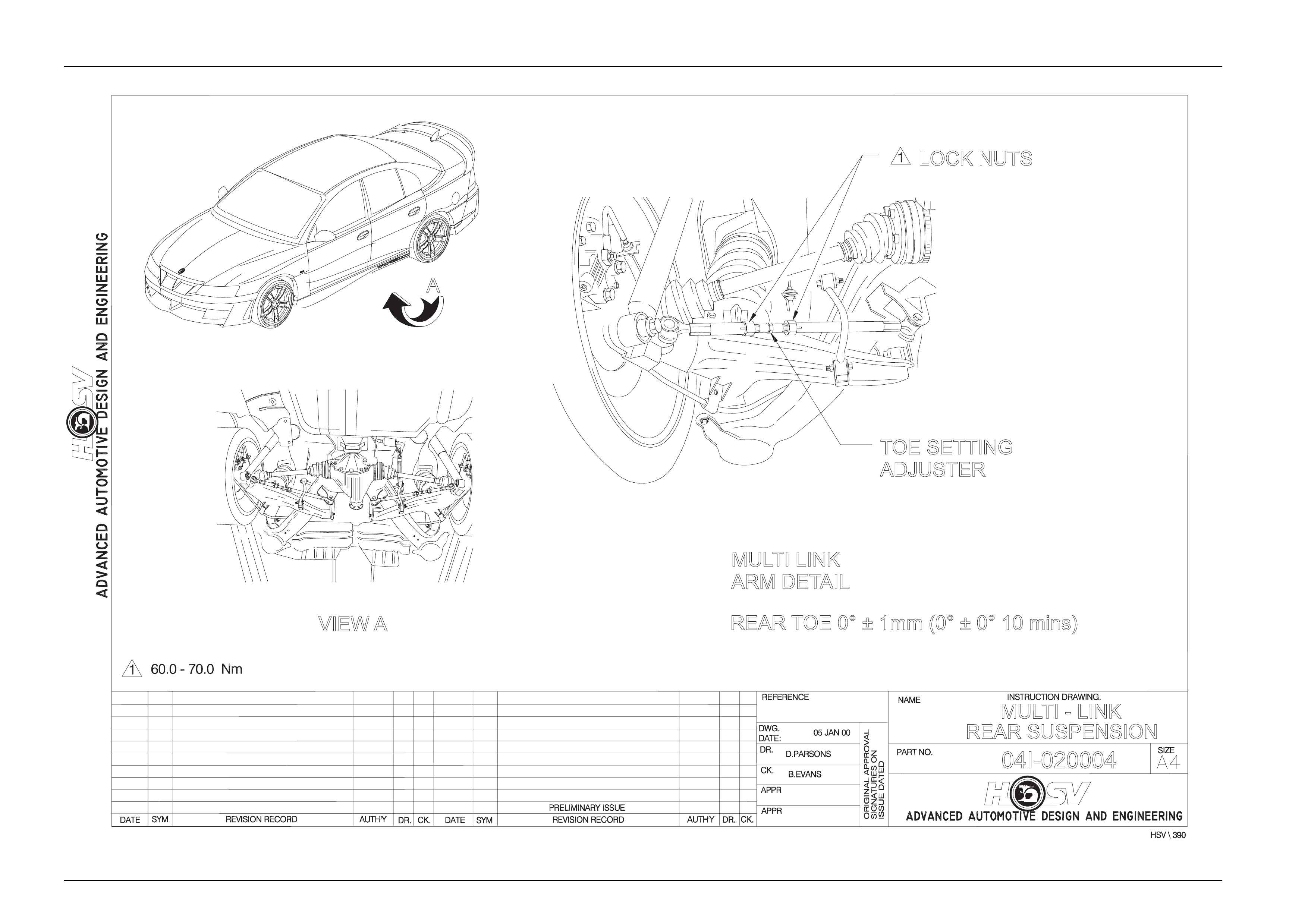
Service Manual Information For Multi Link Irs
Refer: Multilink Rear Suspension Drawing 04I-020004
Suspension Page C-11
Page C-11
A
VIEW A
LOCK NUTS
TOE SETTING
ADJUSTER
MULTI LINK
ARM DETAIL
REAR TOE 0° ± 1mm (0° ± 0° 10 mins)
04I-020004
REAR SUSPENSION
MULTI - LINK

Suspension Page C-12
Page C-12
3.3 Rear Suspension Geometry
The rear suspension is not adjustable, but the geometry is set to:
Camber: - 1°00’ ± 0°30’
T otal Toe: 0°00’ to ± 0°50’

Suspension Page C-13
Page C-13
4 Rear Suspension - Luxury
(Incorporating Automatic Level
Ride)
4.1 General Description
The Level Ride system fitted to HSV VYII Senator and Senator Signature models is the same as the Holden Level Ride
system with the exception of the rear shock absorbers and the Level Ride sensor link, which are HSV components. The
information in this section is designed to supplement the information contained in the Holden VYII service information and
details are given where differences occur between the HSV models and standard Holden models.
A series of instruction drawings describe the design changes and indicate specific part numbers, fitting instructions and
relevant notes for vehicle servicing.
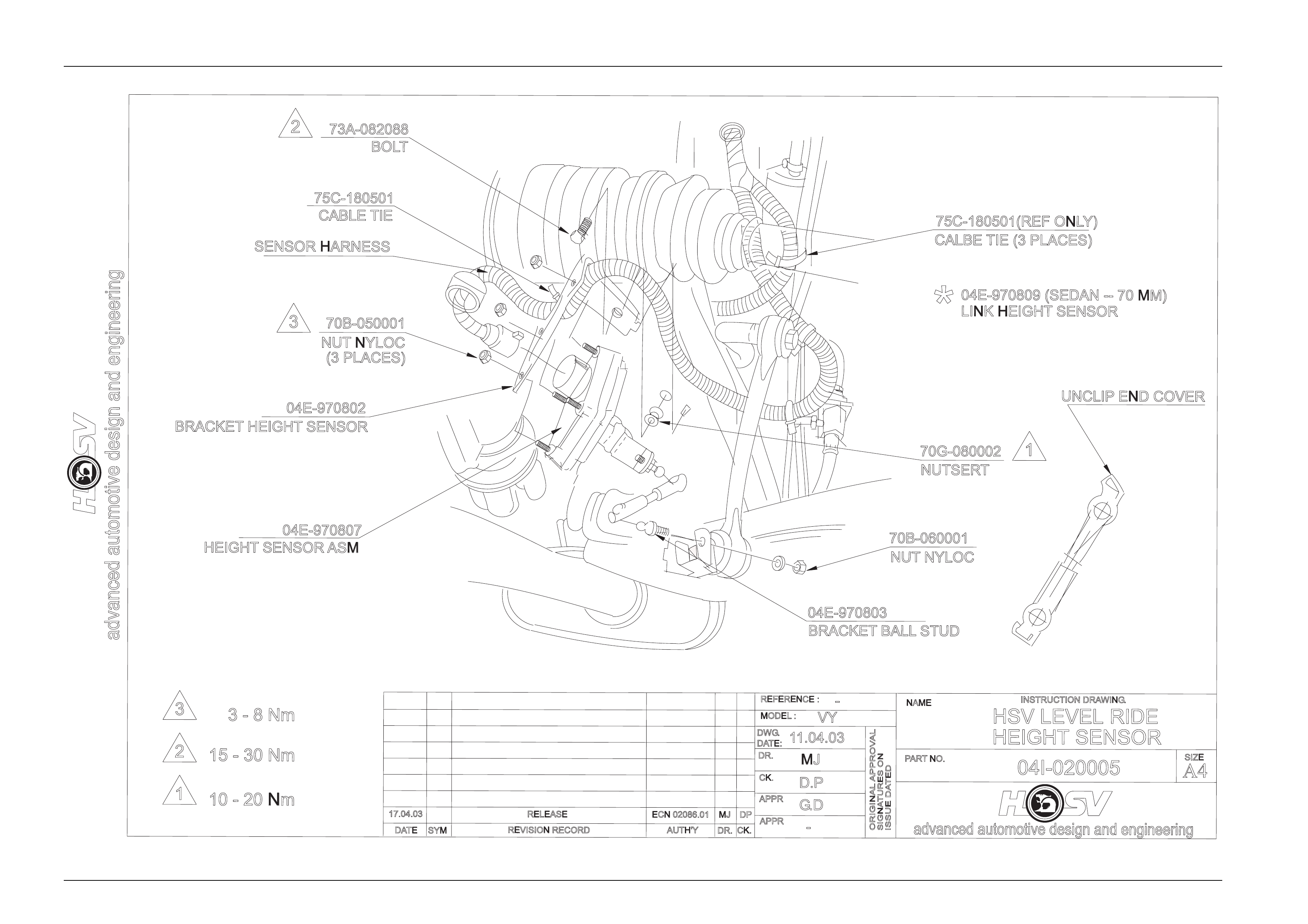
Automatic Level Ride is fitted HSV VYII Senator and Senator Signature models. Automatic Level Ride is an
electronically controlled self levelling system that maintains the vehicle at a constant trim height, independent of load.
This feature uses a specifically designed electronic sensor, fixed to the rear crossmember on the right hand side (see
Drawing 04I-020005), which controls an electric motor driving a single cylinder air compressor, and an exhaust air
solenoid valve. The compressor supplies the necessary pressure to operate the Air Shock Absorbers via "snap on" air
lines. The Air Shock Absorbers assist the rear springs in supporting the vehicle body under all loads.
The sensor has an integrated electronic controller that is programmed to adjust ride height only when necessary, ignoring
sudden changes, as experienced on bumpy roads. The design of the system maintains trim at all times provided the
battery is connected. As a safeguard to prevent the battery being flattened, an electronic timer switches off the
compressor if it runs for a prolonged period (i.e. due to an air leak in the system).
The compressor assembly includes a maximum pressure release valve and an air drier. All air entering or exhausting the
system flows through the dryer, which has an internal minimum pressure retention valve preventing the Air Bag,
surrounding each Shock Absorber, from completely exhausting independent of the sensor controlled exhaust valve.
A number of benefits result from the level ride feature. These include headlamp aim and rear view mirror adjustment
being maintained independent of load, as well as ensuring the rear wheel camber and toe-in are held at the optimum
positions to minimise tyre wear. An additional major benefit is obtained from supplementary design changes that can be
made to spring and damper rates for improved ride quality at all loading conditions with minimum compromise to
handling. These changes are possible since the suspension does not have to be sufficiently stiff to absorb road impacts,
while supporting maximum vehicle load.
Electrical power to operate the Level Ride system is supplied by a separate harness except the Senator Signature model
which uses the main integrated wiring harness and a short ‘patch harness.’
Rear suspension components fitted to HSV vehicles are similar to Holden VYII and details are given where differences
occur. A series of instruction drawings describe design changes and indicate specific part numbers, fitting instructions
and relevant notes for servicing.

Suspension Page C-14
Page C-14
4.2 System Operation
Activation
The sensor's actuating arm is attached to the lower control arm via a connecting link (See Drawing 04I-020005). Before
any activation can occur the actuating arm must remain in either the intake or exhaust zone for a continuous 17 to 20
seconds.
The time delay prevents the compressor or exhaust valve from activating when the vehicle encounters sudden bumps.
Another stability feature is a designed "Deadband". The Deadband helps to minimise hunting by deactivating the
compressor and solenoid when the vehicle trims into or onto one of the Deadband edges. Refer to Figure C-2 for details
on rear suspension trim heights and Deadband.
Loaded Vehicle
When the vehicle is loaded, the vehicle body moves downward into the intake zone, causing the actuating arm to move
upwards. After 17 to 20 seconds, the sensor relieves compressor head pressure by briefly activating the compressor
relay. The compressor starts and pressurises the air shock absorbers until the vehicle body aligns with the bottom edge
of the Deadband, at which point the compressor stops.
Unloaded Vehicle
When the vehicle is unloaded, the vehicle body moves upward into the exhaust zone, causing the actuating arm to move
downwards. After 17 to 20 seconds, the sensor activates the exhaust relay. The exhaust solenoid activates and vents
pressure from the air shock absorbers until the vehicle body aligns with the top edge of the Deadband, at which point the
solenoid deactivates.
Deactivation
The compressor and exhaust solenoid operations are monitored and controlled by individual but interconnected timers.
The timers deactivate specific trimming operations under the following conditions:
a. If the compressor runs for a cumulative time of more than four-and-a-half minutes, the compressor timer deactivates
all system operations.
b. If the exhaust solenoid is active for a cumulative time of more than four-and-a-half minutes, the solenoid timer
deactivates the solenoid.
NOTE
The sensor timers must be reset before any
further operation can take place. The VYII
system is reset after each ignition cycle ON, OFF
for one minute, ON.
Suspension Page C-15
Page C-15
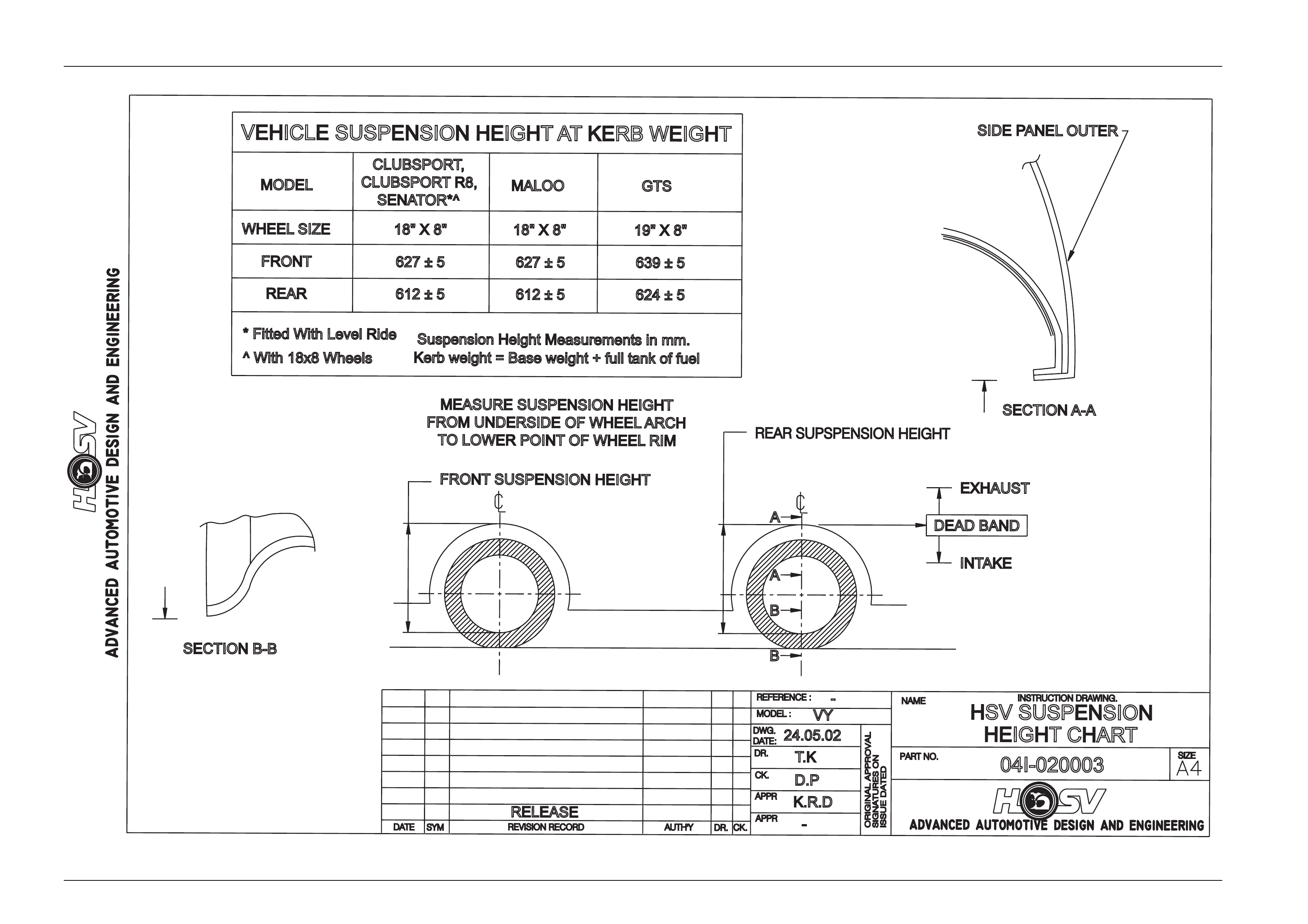
DEAD BAND
INTAKE
EXHAUST
MEASURE SUSPENSION HEIGHT
FROM UNDERSIDE OFW
HEEL ARCH
TOLOWER POINT OFW
HEEL RIM
B
B
A
A
SECTIONA-A
SIDE PANEL OUTER
SECTION B-B
MODEL
WHEEL SIZE
FRONT
REAR
GTS
MALOO
18"X8"
639±5
19"X8"
624±5
VEHICLE SUSPENSION HEIGHT ATKERB WEIGHT
* Fitted With Level Ride Suspension Height Measurementsinmm.
Kerb weight = Base weight + full tank of fuel
DATE REVISION RECORD
RELEASE
SYM DR.
AUTH'Y CK.
K.R.D
-
DWG.
DATE:
24.05.02
D.P
T.K
VY
-
HSV SUSPENSION
HEIGHT CHART
04I-020003
INSTRUCTION DRAWING.
CLUBSPORT,
CLUBSPORTR8,
SENATOR*^
627±5
612±5
18"X8"
627±5
612±5
^W
ith 18x8 Wheels
FRONT SUSPENSION HEIGHT
REAR SUPSPENSION HEIGHT

Suspension Page C-16
Page C-16
Contents of Automatic Level Ride System
VYII LEVEL RIDE SYSTEM
PART NO DESCRIPT ION
04E-970807 HEIGHT SENSOR-ASM
04E-970802 BRACKET HEIGHT SENSOR
70B-050001 NUT NYLOC
73A-082088 BOLT (HT SNSR BRKT TO XMBR)
70G-080002 NUTSERT
04E-970803 BRACKET BALL STUD
04E-970809 LINK HEIGHT SENSOR SED, LUX 70mm
04E-971002 LINK HEIGHT SENSOR WAG, LUX 77mm
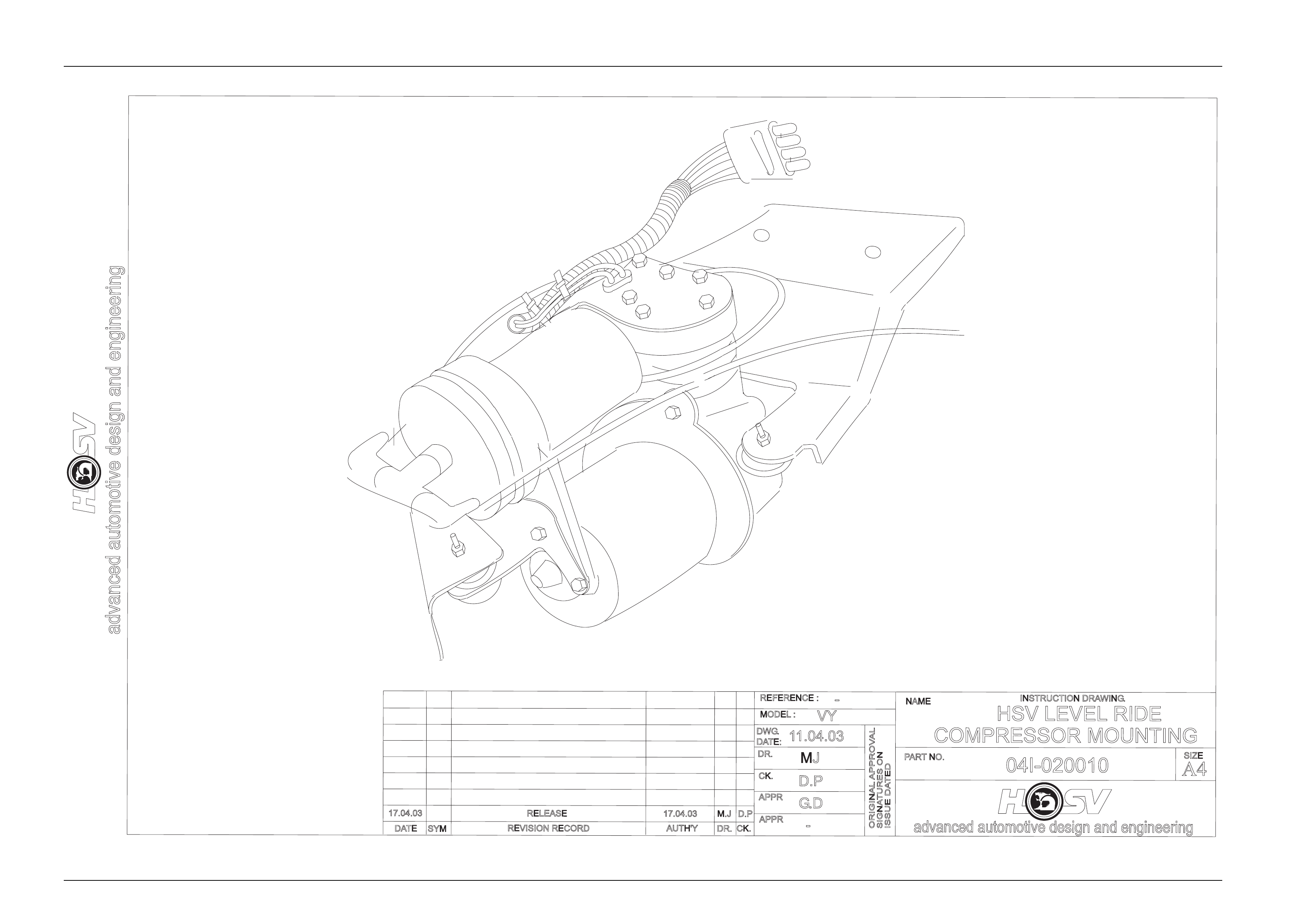
04E-211917 COMPRESSOR
04E-970805 BRACKET COMP TO BODY
73A-053088 BOLT (COMPRESSOR TO BRKT)
72H-970801 BOLT (COMP BRKT TO BODY)
04E-211913 T PIECE
04E-211914 AIR FILTER
75C-180501 CABLE TIE
04E-970806 AIRLINE ASM-COMP T O SHOCK ABSORBER
12H-970801 LEVEL RIDE PATCH HARNESS
12H-970803 LEVEL RIDE UNDERBODY
Suspension Page C-17
Page C-17
advanced automotive design and engineering
DATE SYM
RELEASE
REVISION RECORD
advanced automotive design and engineering
-
REFERENCE :
VY
11.04.03
MJ
D.P
DR.
AUTH'Y
APPR
CK.
-
DR.
APPR
CK.
DWG.
MODEL :
DATE:
SIGNATURES ON
ISSUE DATED
ORIGINAL APPROVAL
NAME
PARTNO.
INSTRUCTION DRAWING.
04I-020005
SIZE
A4
HSV LEVEL RIDE
HEIGHT SENSOR
17.04.03 ECN 02086.01 MJ DP
G.D
75C-180501(REF ONLY)
CALBE TIE (3 PLACES)
04E-970809 (SEDAN -- 70 MM)
LINK HEIGHT SENSOR
*
70B-060001
NUT NYLOC
70G-080002
NUTSERT
UNCLIP END COVER
04E-970803
BRACKET BALL STUD
73A-082088
BOLT
75C-180501
CABLE TIE
SENSOR HARNESS
70B-050001
NUT NYLOC
(3 PLACES)
04E-970802
BRACKET HEIGHT SENSOR
04E-970807
HEIGHT SENSOR ASM
3
2
1
3-8Nm
15-30Nm
10-20Nm
2
3
1

Suspension Page C-18
Page C-18
Air Line And Air Filter - Service
The air line and air filter are serviced as per the standard Holden Level Ride system. Refer to the relevant Holden
Service Manual.
Shock Absorber - Service
The shock absorbers are serviced as per the standard Holden rear shock absorbers. Refer to the relevant Holden
Service Manual.
DO NOT LOWER CAR WITH EMPTY AIR BAGS
AS DAMAGE MAY RESULT. WHENEVER THE
SYSTEM IS UNPRESSURISED OR WHEN THE
VEHICLE REAR SITS OBVIOUSLY HIGH
AFTER LOWERING FROM AN ON-HOIST
OPERATION (SUGGESTING SHOCK
ABSORBER AIR BAGS MAY BE PINCHED OR
JAMMED), IMMEDIATELY RAISE VEHICLE,
DISCONNECT SENSOR CONNECTING LINK,
PUSH SENSOR ARM ABOVE HORIZONTAL
FOR 17 TO 20 SECONDS, AND RUN
COMPRESSOR FOR ABOUT 30 SECONDS TO
INFLATE SHOCK ABSORBERS. RECONNECT
SENSOR CONNECTING LINK AND LOWER
VEHICLE. DRIVING THE VEHICLE WITH
PINCHED OR JAMMED SHOCK ABSORBER
AIR BAGS WILL IRREPAIRABLY DAMAGE
THE SHOCK ABSORBER
Height Sensor - Service
The height sensor assembly is serviced as per the standard Holden Level Ride System. Refer to the relevant Holden
Service Manual.
Relay Control Module - Service
The Relay Control Module is serviced as per the standard Holden Level Ride System. Refer to the relevant Holden
Service Manual.
Diagnostics
General
For diagnosis information on HSV Level Ride Systems refer Holden VYII Series Service Information
Level Ride Specifications
The rear suspension height specifications are shown on Drawing 04I-020003.
To achieve this specification note the following:
1. The vehicle must be at kerb weight, see Drawing 04I-020003.
2. The internal angle of the Height Sensor Bracket is 80 degrees
Suspension Page C-19
Page C-19
advanced automotive design and engineering
DATE SYM
RELEASE
REVISION RECORD
advanced automotive design and engineering
-
REFERENCE :
VY
11.04.03
MJ
D.P
DR.
AUTH'Y
APPR
CK.
-
DR.
APPR
CK.
DWG.
MODEL :
DATE:
SIGNATURES ON
ISSUE DATED
ORIGINAL APPROVAL
NAME
PARTNO.
INSTRUCTION DRAWING.
04I-020010
SIZE
A4
HSV LEVEL RIDE
COMPRESSOR MOUNTING
G.D
17.04.03 17.04.03 M.J D.P

Suspension Page C-20
Page C-20
4.4 Service Operations
Service Operations and Service Intervals for HSV Rear Suspension assemblies are the same as those detailed in the
relevant Holden VYII Service Manual except when detailed otherwise in this supplement.
The Height Sensor Link part number and length for each Level Ride application is as follows:
• 04E-970809 (VYII SEDAN - 70mm)
For rear wheel alignment specification, refer to Section 4A Rear Suspension. For trim height specifications refer to
Drawing 04I-020003.
Wiring connections for the VYII system are shown in Section 12O – Fuses, Relays and Wiring Harnesses or
Section 12P – Wiring Diagrams.

Suspension Page C-21
Page C-21
5 Rear Axle
5.1 General
HSV VYII models are equipped with a Hydratrak Differential ( a specifically designed Viscous coupling type limited slip
differential).
• Manual transmission LS1 vehicles final drive ratio is 3.73:1 and the differential (Part No.92082622) can be identified
by Broadcast Code ET.
• Manual transmission VYII GTS vehicles final drive ratio is 3.91:1 and the differential (Part No. 92089748) can be
identified by Broadcast Code CK.
• Automatic transmission LS1 vehicles final drive ratio is 3.07:1 and the differential (Part No. 9205342) can be
identified by Broadcast Code EH.
• Automatic transmission VYII GTS vehicles final drive ration 3.46:1 and the differential (Part No. 92085135) can be
identified by Broadcast Code FP.
Suspension Page C-22
Page C-22
5.2 Service Operations
The differential oil must be changed at 45,000 km intervals. Use synthetic hypoid gear oil to HN2040 such as ‘Mobilube
SHC 80W-140 ID’.
The viscous coupling cartridge assembly is a sealed unit and must be replaced as a complete assembly if required.
General service operations are the same as those described in the Holden VS series Service Manual however, to
determine if the Hydratrak coupling cartridge is faulty, undertake the following torque check. The Hydratrak rear axle
assembly is covered by the current Axle Warranty Changeover agreement between GMHAL and BTR Engineering (refer
GMHA Dealer Bulletins).
Torque Check
i. Place transmission in neutral with engine turned 'OFF'.
ii. Jack up one rear wheel, then release park brake lever to fully 'OFF' position. Support vehicle body on a safety
stand.
iii. Remove centre cap (alloy wheels).
iv. Mark relationship of road wheel to axle flange. Remove road wheel attaching nuts and remove wheel.
v. Remove caliper attaching bolts and remove caliper from mounting, refer Section 5 BRAKES in the Holden
Commodore Service Manual No. 2. Support caliper on a wire hook. Remove brake disc.
DO NOT ALLOW CALIPER TO HANG BY
BRAKE HOSE
vi. Using a torque wrench in conjunction with adaptor, Tool No. 4A48, and torque wrench adaptor E6662B, rotate axle
shaft in forward direction. If the unit is operating satisfactorily, a torque reading of 35 Nm should be obtained whilst
turning the axle shaft at 20 rpm (e.g. one third of a turn per second).
If a torque reading of less than 25 Nm or more than 80 Nm (@ 20 rpm) is obtained, remove differential case and
inspect the differential components and repair or replace as necessary.
However, if the Hydratrak Coupling cartridge unit is faulty it will require replacement with a new Coupling unit, as it is
a sealed, non-serviceable fluid filled component.
DO NOT ATTEMPT TO REPAIR OR WELD THE
COUPLING UNIT.

Suspension Page C-23
Page C-23
vii. Install brake disc and caliper. Tighten caliper attaching bolts to the correct torque specification.
NOTE
CALIPER ATTACHING BOLT TORQUE
SPECIFICATION IS 55- 70Nm
viii. Install road wheel.
NOTE
When installing the wheel, align the marks made
prior to removal.
ix. Remove safety stand and lower vehicle.
x. Tighten road wheel attaching nuts to the correct torque specification.
NOTE
TORQUE SPECIFICATION IS 100-125Nm
xi. Refit wheel cover/centre cap.

Suspension Page C-24
Page C-24
6 Limited Slip Differential
From Holden Commodore VS series Service Manual
When servicing a vehicle fitted with a Limited
Slip Differential (including Hydratrack type),
never run the engine with the transmission in
gear and one wheel raised. The driving force
to the wheel on the ground may cause the
vehicle to move.
NOTE
'On Car' type wheel balancers are not
recommended for use on the rear wheels of cars
equipped with a Limited Slip Differential. One
rear wheel will drive if in contact with the ground
when the opposite wheel is raised. This type of
balancer may be used by removing the wheel
opposite to the one being balanced with the
vehicle raised and supported on safety stands.
(Refit wheel nuts, reversed, to retain brake disc).

Suspension Page C-25
Page C-25
7 Propeller Shaft And Universal
Joints
All other HSV models use standard GMHA propeller and drive shafts.
7.1 Service Operations
Service procedures for propeller shaft assemblies fitted to HSV models are the same as those described in the Holden
VYII series Service Manual.