
Engines Page E-1
Page E-1
Section E
Engines
ATTENTION
HSV vehicles are equipped with a Supplemental Restraint System (SRS). An SRS consists of seat belt pre-
tensioners (fitted to all front seats), a driver’s-side air bag, a passenger’s-side air b ag and left and right hand
side air bags. Refer to CAUTIONS, Section 12M, in Volume 12 of the Holden VYII series Service Manual before
performing any service operation on or around SRS components, the steering mechanism or wiring. Failure
to follow the CAUTIONS could result in personal injury or unnecessary SRS system repairs.
1 Purpose...............................................................................................................................................E-2
2 Engines - General Information..........................................................................................................E-3
Engine Dress Covers..........................................................................................................................................E-3
Engine Air Induction System.............................................................................................................................E-3
Specific HSV Engine Components....................................................................................................................E-4
3 Clubsport, R8 And Senator 285 LS1.................................................................................................E-5
3.1 General Description............................................................................................................................................E-5
3.2 Service Operations .............................................................................................................................................E-6
4 GTS 300 C4B LS1 ...............................................................................................................................E-9
4.1 General Description............................................................................................................................................E-9
4.2 Service Operations ..........................................................................................................................................E-11
4.3 Engine Assembly – Service..............................................................................................................................E-12
Techline
Techline

Engines Page E-2
Page E-2
1 Purpose
The purpose of this supplement is to provide information on the various engine packages fitted to the HSV VYII models.
This information is designed to supplement that given in the Holden VYII series Service Manuals, and details are given
where differences occur between the HSV models, and standard Holden models. A series of instruction drawings detail
the design changes and indicate specific part numbers, fitting instructions and relevant notes for vehicle servicing.
NOTE:
If specific technical data on a HSV model is not
contained in this supplement, obtain data for that
model from the relevant Holden VYII series
Service Manual Supplement. References are
made throughout this section to Holden Service
Manuals, to assist in providing information for
specific service operations.
When hoisting (or jacking) HSV models,
ensure that the liftin g head of the hoist lifts on
the chassis before the arm of the hoist
contacts the side-skirt

Engines Page E-3
Page E-3
2 Engines - General Information
VYII sees the carry over of the two Chevrolet Generation 111 engines introduced into the HSV range during VT2.
These engines have both received upgrades to the base engine as manufactured by GM, resulting in improvements over
the VT2 engine.
The 285 LS1 engine is not modified internally by HSV, and uses an HSV specific calibration to optimise the benefits of
the specific HSV exhaust and inlet systems. As part of the development process, these changes have been proven
through extensive testing throughout Australia, as is the case with all engines fitted to HSV models.
The 300kW C4B engine is fitted with unique HSV components, such as camshaft, pistons, valve train and the like. It
should be noted however, that assembly procedures, torque settings, engine diagnosis, valve timing procedures and
other parameters are the same as for the standard GMHA product unless stated otherwise in this supplement. The
various HSV engines are discussed in the following paragraphs.
Engine Dress Covers
The HSV LS1 V8 engine is fitted with a specific decorative engine cover. This is a large one piece plastic cover that
encases the fuel rail and coil packs, as well as the inlet manifold and throttle body. The cover includes a moulded-in HSV
Lion and Helmet logo, and is painted black, with silver highlights.
The HSV C4B LS1 V8 engine comes with specifically designed engine covers, that cover the two banks of the engine,
leaving the centre of the inlet manifold exposed. The covers are painted and moulded in a red polypropylene copolymer,
and incorporate HSV logos and 300kW signage.
LS1
06M-990601 COVER ASM: LS-1 ENGINE (SILVER HIGHLIGHT)
C4B LS1
06M-990701 COVER - ENGINE RH-GTS
06M-990702 COVER - ENGINE LH-GTS
Engine Air Induction System
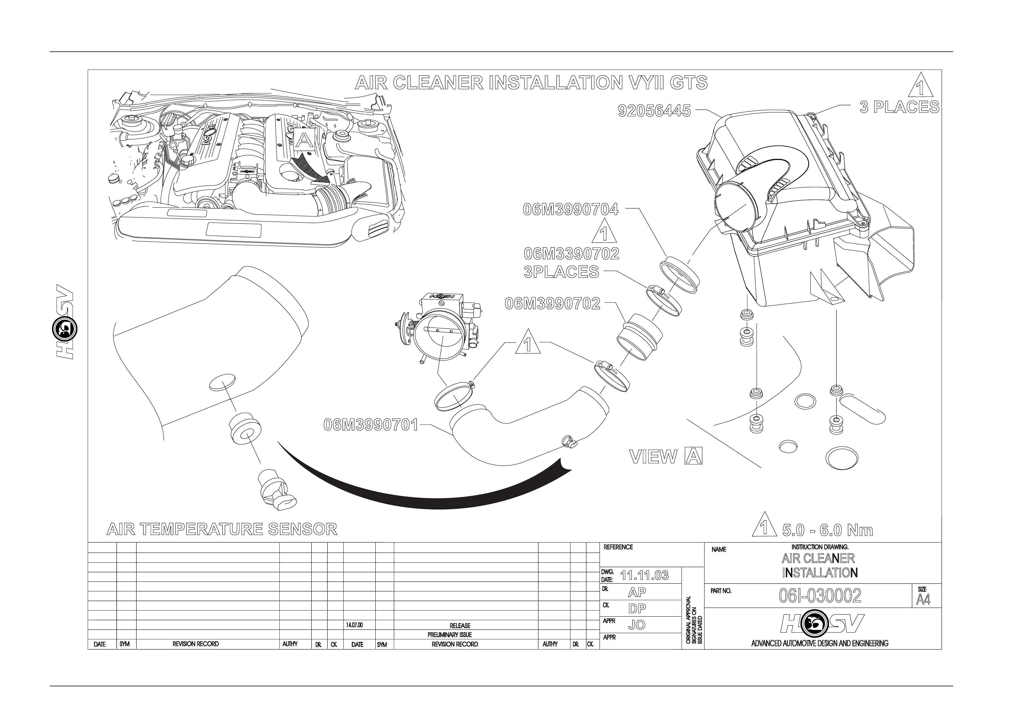
The air induction system on the HSV C4B LS1(300kw) varies from the standard Holden and HSV 285 kw system, in that
it does not use the original equipment Mass Air Flow (MAF) Sensor. Instead, the engine runs on a speed/density based
calibration system, using a Manifold Absolute Pressure (MAP) Sensor, Intake Air Temperature (IAT) Sensor and engine
rpm to calculate the mass of air entering the engine. Due to this change, the C4B engine uses a specific duct and boot
combination from the airbox to the throttle body. As part of these changes, the IAT sensor is relocated to the inlet duct,
as this gives faster response to changing intake air temperature changes.
The rest of the intake system is common with the 285 LS1 introduced with VYII, and this incorporates much of the
standard Holden system, with the difference being concentrated on ensuring the engine receives as much cold air as
possible. This was found to give the greatest performance advantage, and also helped reduce the performance lost due
to stop start warm weather driving.
The intake system on the HSV LS1 uses the standard Holden air filter element, Mass Air Flow (MAF) Sensor and Inlet Air
Temperature (IAT) sensor. Service requirements for the filter are described in the Holden service manual, and no
adjustment is possible on the MAF sensor.
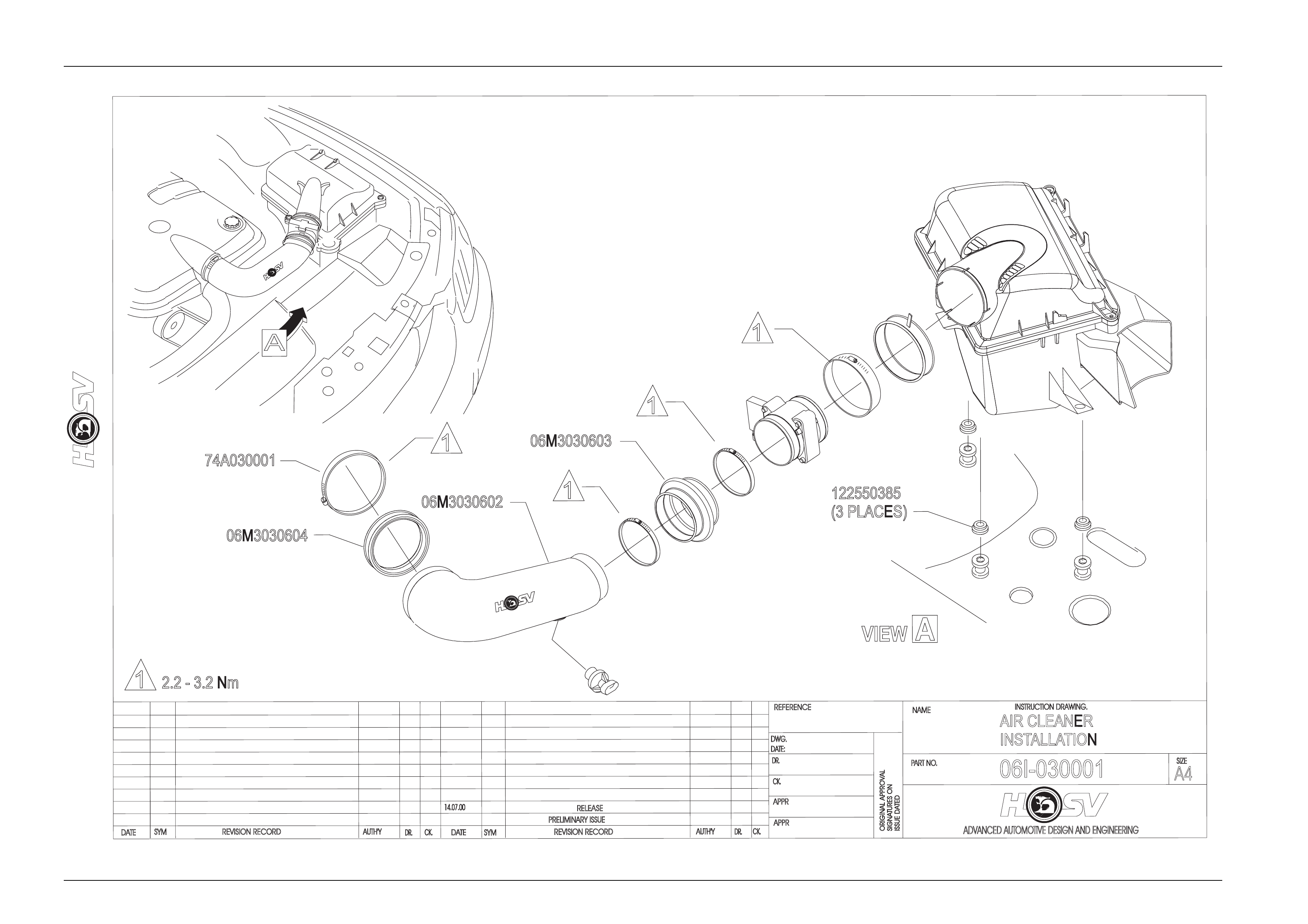
To remove the HSV inlet duct, it is necessary to release the coolant system surge tank from its locating studs, then pull
the airbox base away from its locating studs, pulling the rear away first, and then away from the inlet duct. To remove the
duct, it is best to take the outboard edge of the duct and rotate it inboard and up to clear bodywork, then pull out.
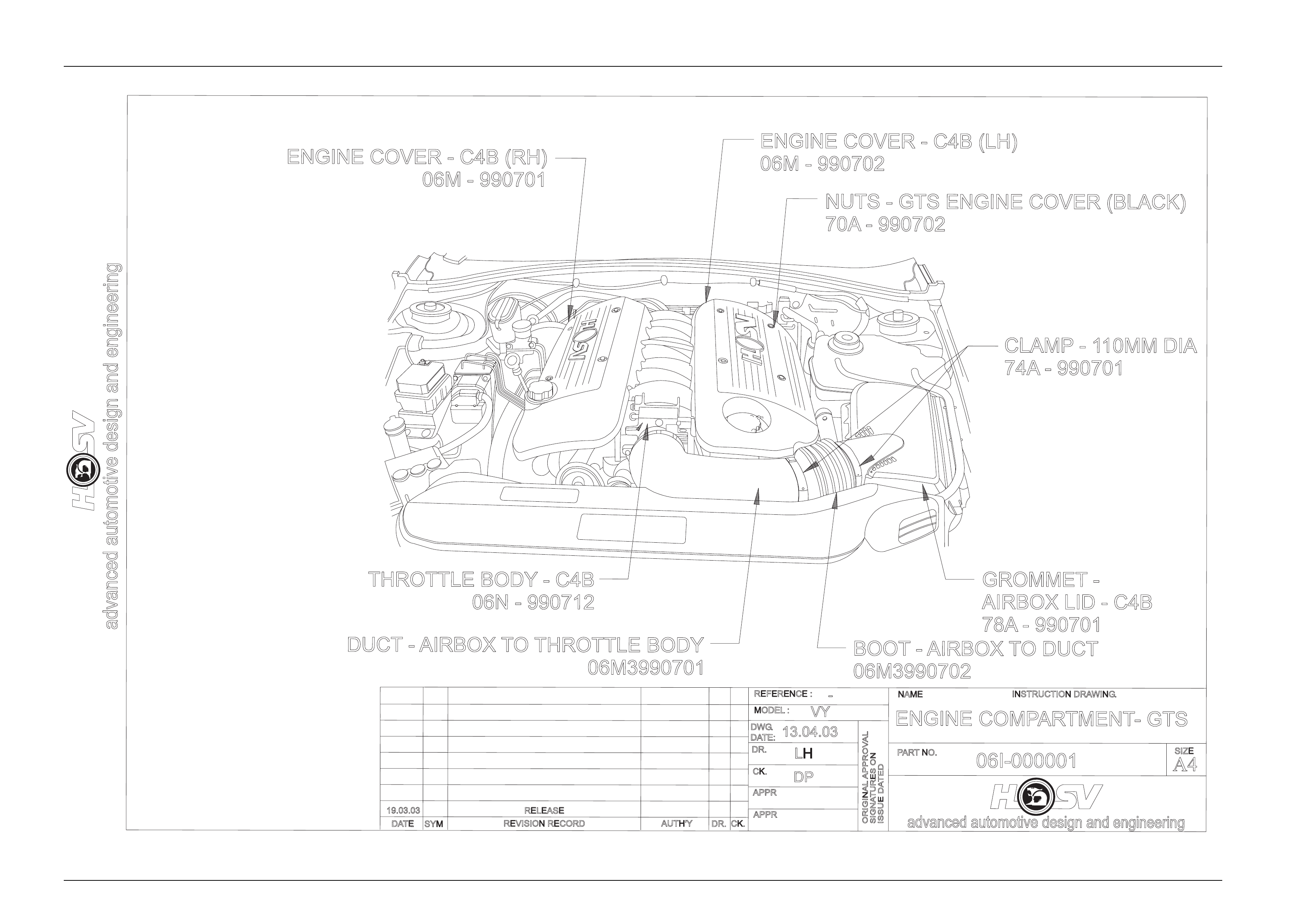
For replacement part numbers see Drawings 06I-030001, 06I-000001, 06I-030002.

Engines Page E-4
Page E-4
Specific HSV Engine Components
As the HSV C4B LS1 engine is a specific assembly for HSV, there are several components that warrant a specific
mention in this section. These components are the specific valve springs, which are of a constant diameter, and made
from an oval formed wire, specific Titanium valve spring retainers to match the springs, and a new, high lift camshaft.
Details of this new camshaft are detailed in the table below:
HSV C4B CAMSHAFT SPECIFICATION
INTAKE EXHAUST
Lobe Lift 8.331mm (0.327”) 8.356mm (0.329”)
Duration at 1.27mm (0.050”) lift 184.7° 189.0°
Duration 278.8° 283.0°
Valve Timing at 1.27mm (0.050”)
lift
-Open
-Close
25.1° ATDC
29.8° ABDC
31.3° BBDC
22.3° BTDC

Engines Page E-5
Page E-5
3 Clubsport, R8 And Senator 285
LS1
3.1 General Description.
All HSV VYII V8 models use the new, Chevrolet developed LS1 engine. This engine is common with the Holden Gen III
V8 engine, and has a capacity of 5667m3, produced by a bore of 99.00mm and a stroke of 92.00 mm. The compression
ratio for this engine is 10.1:1.
The base engine design is that of a 90° V8, two valve per cylinder engine. The engine features an aluminium block and
heads, with cast iron sleeves cast into the block
during manufacture, while the heads have powdered metal valve guides and seats pressed in place.
For more information regarding the LS1 engine, see the relevant section in Holden's VY Service information.
The HSV LS1 engine has an optimised Cold air Induction System, including a
Low Restriction large diameter ‘Zip Tube’,a Low Restriction Exhaust System and an Optimised Engine Management
System. These improvements allow the engine to develop 285kW at 5,800 rpm and 510Nm at 4,800 rpm.

Engines Page E-6
Page E-6
3.2 Service Operations
The HSV LS1 engine fitted to ClubSport,Senator and Maloo models are to be serviced in accordance with the procedures
detailed in the Holden VYII series service information.
Engines Page E-7
Page E-7
DATE
ISSUE DATED
AUTH'Y
CK.
SYM
AUTH'Y
RELEASE
REVISION RECORD
DATE
SYM
SIGNATURES ON
ORIGINAL APPROVAL
DR.
14.07.00
ADVANCED AUTOMOTIVE DESIGN AND ENGINEERING
06I-030001
INSTRUCTION DRAWING.
A4
SIZE
AIR CLEANER
INSTALLATION
06M3030603
06M3030602
06M3030604
2.2 - 3.2 Nm
74A030001
122550385
(3 PLACES)
REVISION RECORD
PRELIMINARY ISSUE
CK.
NAME
PART NO.
CK.
REFERENCE
DWG.
DR.
DATE:
APPR
APPR
DR.
07.11.03
AP
DP
JO
A
A
VIEW
1
1
1
1
1
Engines Page E-8
Page E-8
DATE
ISSUE DATED
AUTH'Y
CK.
SYM
AUTH'Y
RELEASE
REVISION RECORD
DATE
SYM
SIGNATURES ON
ORIGINAL APPROVAL
DR.
14.07.00
ADVANCED AUTOMOTIVE DESIGN AND ENGINEERING
06I-030002
INSTRUCTION DRAWING.
A4
SIZE
AIR CLEANER
INSTALLATION
REVISION RECORD
PRELIMINARY ISSUE
CK.
NAME
PART NO.
CK.
REFERENCE
DWG.
DR.
DATE:
APPR
APPR
DR.
11.11.03
AP
DP
JO
AIR CLEANER INSTALLATION VYII GTS
AIR TEMPERATURE SENSOR 5.0 - 6.0 Nm
3 PLACES
92056445
06M3990704
06M3990702
06M3990701
06M3390702
3PLACES
A
VIEW A
1
1
1
1

Engines Page E-9
Page E-9
4 GTS 300 C4B LS1
4.1 General Description
The HSV GTS is the second tier engine to HSV. With a Holden production option designation of C4B, this engine is
based on the standard LS1 engine common with the 260kW models. The differences over the LS1 engine are related to
cylinder head and camshaft modifications.
The engine hardware was developed in conjunction with Callaway Cars in the USA, and the rest of the vehicle
development and validation carried out by HSV.
The changes included a specific camshaft, upgraded valve springs and titanium valve spring retainers, stainless steel
intake and exhaust valves, revised cylinder head porting and combustion chamber modifications, and a specific, larger
bore machined throttle body. The throttle body is the easiest identifier for the engine, as it is anodised bright red.
Additional marking is also evident on the cylinder heads, where the C4B designation is machined into the head, on the
exhaust port face.
The swept volume of the C4B LS1 engine is unchanged from the LS1 engine, although, due to the combustion chamber
modifications the compression ratio has been lowered slightly to 9.95:1. This gives improved engine performance across
the entire speed range, as it allows more spark advance, due to less knock sensitivity, to be calibrated into the engine,
particularly at low to medium engine speeds.
The HSV C4B LS1 engine uses a high flow induction system, that does not require a Mass Air Flow Meter, and
incorporates this with the optimised Cold air Induction System, a Low Restriction Exhaust System (including a specific,
straight through design rear muffler) and an Optimised Engine Management System. These improvements allow the
engine to develop 300kW at 6,000 rpm and 510 Nm at 4,800 rpm.
Techline
Engines Page E-10
Page E-10
advanced automotive design and engineering
RELEASE
REVISION RECORD
SYM
DATE
INSTRUCTION DRAWING.
advanced automotive design and engineering
SIGNATURES ON
ISSUE DATED
ORIGINAL APPROVAL
AUTH'YCK.
DR.
APPR
VY
LH
13.04.03
APPR
CK.
DR.
MODEL :
DWG.
DATE:
REFERENCE :
PARTNO.
-
NAME
ENGINE COMPARTMENT- GTS
A4
SIZE
19.03.03
06I-000001
DP
DUCT -AIRBOX TOTHROTTLE BODY
06M3990701
THROTTLE BODY - C4B
06N - 990712
BOOT -AIRBOX TO DUCT
06M3990702
GROMMET -
AIRBOX LID - C4B
78A - 990701
CLAMP -1
10MM DIA
74A - 990701
NUTS - GTS ENGINE COVER (BLACK)
70A - 990702
ENGINE COVER - C4B (LH)
06M - 990702
ENGINE COVER - C4B (RH)
06M - 990701

Engines Page E-11
Page E-11
4.2 Service Operations
The HSV C4B LS1 engine fitted to the VY GTS is to be serviced in accordance with the procedures detailed in the VT
Series II Service Information however, due to the deletion of the MAF sensor, the following service bulletin was released
by HSV.
Dealer Bulletin - HSV GTS MAF Sensor Deletion
As part of the modifications made by HSV to achieve the 300kW output of the C4B engine, it was decided to use the less
restrictive Speed/Density calibration system. This allowed HSV to remove the Mass Air Flow (MAF) Sensor from the
intake system, removing the restriction it creates at high engine speeds advance requirements of the engine by using a
software model. This model incorporates inputs from the Manifold Absolute Pressure (MAP) Sensor, along with the Inlet
Air Temperature (IAT) Sensor and the engine rpm to predict airflow rate and volume into the engine, and therefore
fuelling requirements.
One effect of this system is that the engine no longer runs on 2 separate spark maps, resulting in the potential for some
audible knock under certain conditions when using 91 Ron Unleaded. It should be noted that the engine still runs an
advanced knock control, and a level of detonation will not harm the engine.
When carrying out diagnostic work on the HSV VY GTS, it is important that you are aware that the PCM will always log
Diagnostic Trouble Code 0102-Mass Air Flow Sensor Circuit Low Frequency. The calibration has been modified to
prevent the Malfunction Indicator Lamp from illuminating at this DTC the Instrument will also log an fault code in this case
DTC 19, which indicates that the instrument has detected a fault code in the PCM.
HSV GTS vehicles are also fitted with a PCM containing a specific engine calibration. This PCM is serviced in the same
manner as that for the HSV LS1 PCM.
For calibration details use TECH 2 to obtain data from PCM. Connect to TIS 2000, go to Service Program System and
check for calibration update. If vehicle has latest calibration no changes will be permitted

Engines Page E-12
Page E-12
4.3 Engine Assembly - Service
Specific HSV components that have been included in the LS1 C4B 300 engine assembly are detailed below. The part
numbers for these components are listed for servicing requirements.
06Z-030701 ENGINE ASM-LS1 C4B AS SHIPPED
06X-990702 CAMSHAFT-C4B
06X-990703 VALVE SPRING-C4B
06X-990704 RETAINER-VALVE SPRING
06X-990705 SHIM-0.030"
06X-990706 SHIM-0.015"
06X-990707 VALVE-XHAUST-C4B
06X-990708 VALVE-INLET-C4B
06A-990709 CYLINDER HEAD-MACHINED-C4B
06A-990710 CYLINDER HEAD ASM-C4B
06N-020712 THROTTLE BODY-C4B