
Wheels, Tyres And Steering Wheel Page H-1
Page H-1
Section H
Wheels, Tyres And Steering Wheel
ATTENTION
HSV vehicles are equipped with a Supplemental Restraint System (SRS). An SRS consists of seat belt pre-
tensioners (fitted to all front seat s), a driver’s-side air bag, a passeng er’s-side air bag and left and right h and
side airbags. Refer to C AUTIONS, Section 12M, in Volume 12 of the Holden series VYII Ser vice Manual before
performing any service operation on or around SRS components, the steering mechanism or wiring. Failure
to follow the CAUTIONS could result in personal injury or unnecess ary SRS system repairs.
1 Purpose...............................................................................................................................................H-2
2 Wheels And Tyres ..............................................................................................................................H-3
2.1 General Description............................................................................................................................................H-3
3 Service Operations.............................................................................................................................H-4
3.1 Wheel and Tyre Balancing .................................................................................................................................H-4
3.2 HSV Wheel and Tyre Combinations..................................................................................................................H-5
3.3 Tyre Placard And Pressures............................................................................................................................H-11
3.4 Loading The HSV Maloo...................................................................................................................................H-12
3.5 HSV Temporary Spare Tyre..............................................................................................................................H-13
4 Steering Wheel..................................................................................................................................H-14
Techline
Wheels, Tyres And Steering Wheel Page H-2
Page H-2
1 Purpose
The purpose of this section is to provide information on the wheels, tyres and steering wheels fitted to the HSV VYII
model. The information is designed to supplement that given in the Holden VYII series Service Manual and details are
given where differences occur between the HSV models and sta ndard Holden models. A series of i nstruction dra wings
describe the design changes and indicate specific part numbers, fitting instructions and relevant notes for vehicle
servicing.
NOTE
If specific technical data on a HSV model is not
contained in this supplement, obtain data for that
model from the relevant Holden VYII series
Manual Supplement. References are made
throughout this section to Holden Service
Manuals, to assist in providing information for
specific service operations.
When hoisting (or jacking) HSV models,
ensure that the lifting h ead of the hoist lifts on
the chassis before the arm of the hoist
contacts the side-skirt
Wheels, Tyres And Steering Wheel Page H-3
Page H-3
2 Wheels And Tyres
2.1 General Description
HSV VYII models are fitted with alloy wheels dev eloped specifically for e ach HSV application. S everal types and sizes of
wheel are manufactured to suit the various applications and each wheel is manufactured from a single-piece alloy
casting.
NOTE
Specific wheel nuts are used to attach alloy
wheels to the vehicle. These nuts are fitted with
a plastic dress cap which must be removed prior
to undoing the wheel nuts.
HSV VYII wheels do not have a steel insert
and therefore require wheel nuts with a
flanged seat as per the VT, VT2 and VX wheel
nuts, 10B-970304. Do no t use VS wheels nuts
on HSV VY wheels.

Wheels, Tyres And Steering Wheel Page H-4
Page H-4
3 Service Operations
Alloy wheels fitted to all HSV vehicles are to be serviced in accordance with the procedures detailed in the relevant
Holden Service Manual, refer to Section 10 – Wheels And Tyres. In addition, particular care should be taken with the
surface finish of alloy wheels. The manufacturer recommends that alloy surfaces be treated the same as high-gloss
painted services to prevent corrosion and genera l deteriorat ion.
3.1 Wheel and Tyre Balancing
In order to balance the HSV Design wheels and t yre assemblies, refer to the relevant Hol den series Service Information,
refer to Section 10 – WHEELS AND TYRES of the VT Series II Service Information.
NOTE
HSV wheels are balanced with concealed
weights. The lateral distance between these
weights is considerabl y less than the actua l width
of the wheel. To achieve wheel balance within
specification with concealed balance weights, set
the balancing machine for a wheel width of 5.5".
Wheels, Tyres And Steering Wheel Page H-5
Page H-5
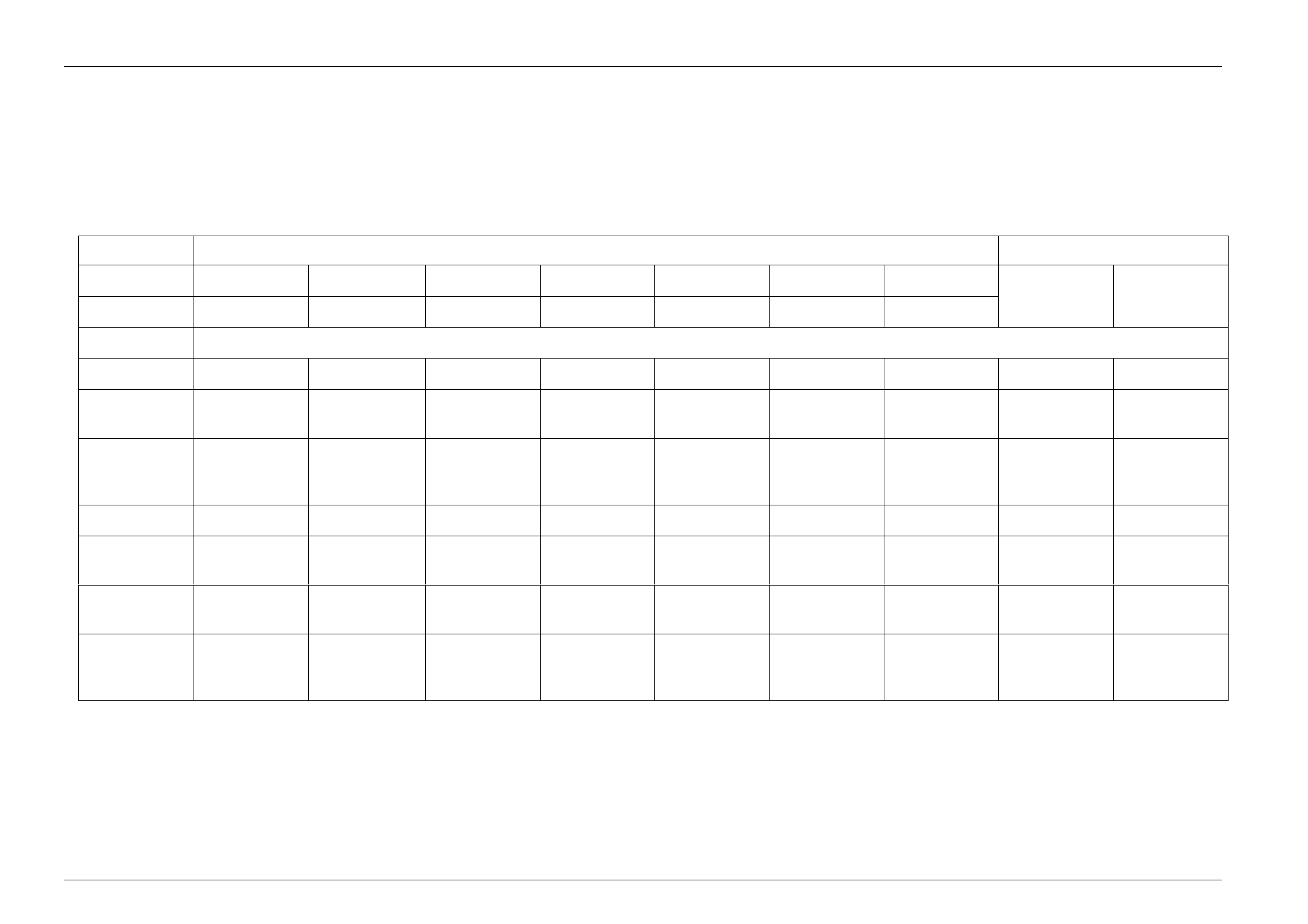
3.2 HSV Wheel and Tyre Combinations
The following HSV Wheels and tyre combination are fitted to VYII.
Refer to drawings 10I-020001, 10I-020002, 10I-020003, 10I-010002, 10I-020005.
VYII WHEEL AND TYRE MATRIX
WHEEL TYRE
WHEEL SIZE 18” X 8.00 19” X 8.00 19” X 8.00 18” X 8.00 19” X 8.00 18” X 8.00 19” X 8.00
PART NO 10B020601 10B000701SS 10B000701 10B020601C 10B020701 10B020801 10B020804 235/40 ZR18 245/35 ZR19
MODEL
VYII GTS S S
VYII
CLUBSPORT S O S O
VYII
CLUBSPORT
R8 S S
VYII MALOO S S
VYII MALOO
R8 S S
VYII
SENATOR O S S O
VYII
SENATOR
SIG O S O
Wheels, Tyres And Steering Wheel Page H-6
Page H-6
SECTION
100 - 125 Nm
A-A
advanced automotive design and engineering
RELEASE
1
INSTRUCTION DRAWING.
advanced automotive design and engineering
M.B
SIGNATURES ON
ISSUE DATED
ORIGINAL APPROVAL
APPR
VY
T.K
D.P
20.05.02
APPR
CK.
DR.
MODEL :
DWG.
DATE:
REFERENCE :
PARTNO.
10I-020002
-
NAME
ALLOY WHEEL CLUBSPORT,
MALOO R8
MALOO,
A4
SIZE
REVISION RECORD
SYM
DATE AUTH'Y CK.
DR.
-
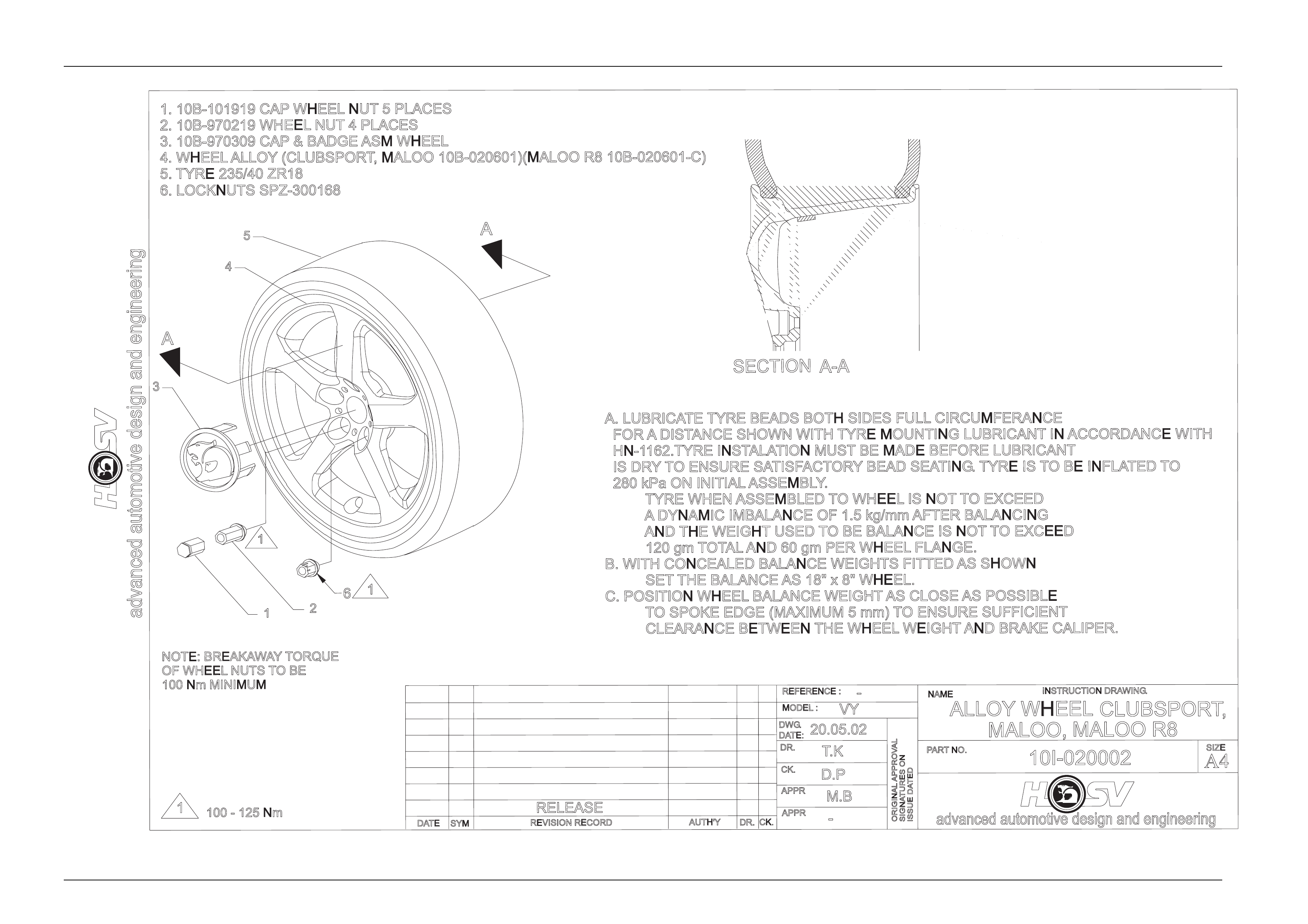
A. LUBRICATE TYRE BEADS BOTH SIDES FULL CIRCUMFERANCE
FOR ADISTANCE SHOWN WITH TYRE MOUNTING LUBRICANT IN ACCORDANCE WITH
HN-1162.TYRE INSTALATION MUST BE MADE BEFORE LUBRICANT
IS DRYTO ENSURE SATISFACTORYBEAD SEATING.TYRE IS TO BE INFLATED TO
280 kPa ON INITIAL ASSEMBLY
.
TYRE WHEN ASSEMBLED TO WHEEL IS NOT TO EXCEED
ADYNAMIC IMBALANCE OF 1.5 kg/mm AFTER BALANCING
AND THE WEIGHT USED TO BE BALANCE IS NOT TO EXCEED
120 gm TOTAL AND 60 gm PER WHEEL FLANGE.
B. WITH CONCEALED BALANCE WEIGHTS FITTED AS SHOWN
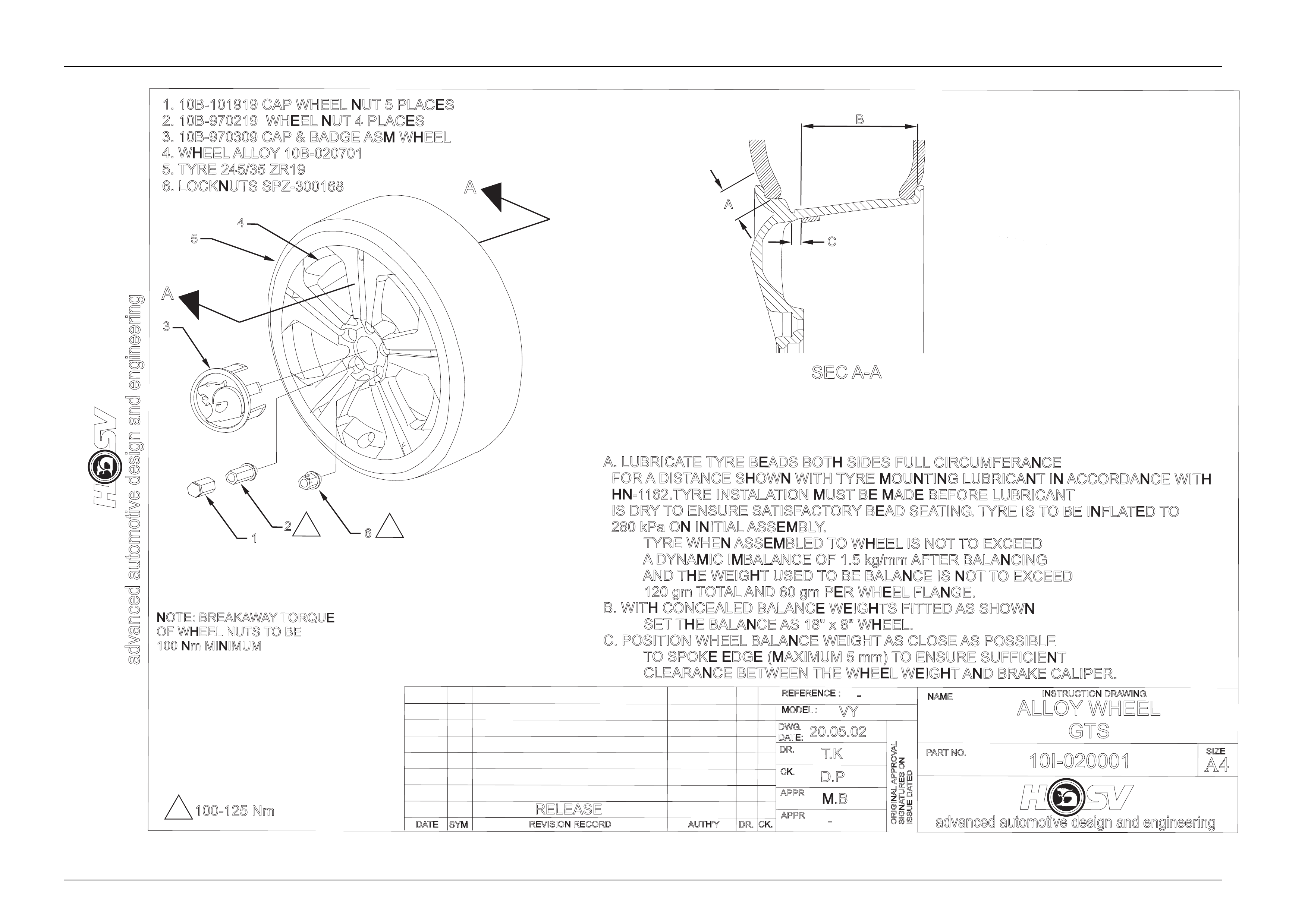
SET THE BALANCE AS 18" x 8" WHEEL.
C. POSITION WHEEL BALANCE WEIGHT AS CLOSE AS POSSIBLE
TO SPOKE EDGE (MAXIMUM 5 mm) TO ENSURE SUFFICIENT
CLEARANCE BETWEEN THE WHEEL WEIGHT AND BRAKE CALIPER.
NOTE: BREAKAWAYTORQUE
OF WHEEL NUTS TOBE
100 Nm MINIMUM
1
2
1
3
4
5
A
A
1. 10B-101919 CAP WHEEL NUT 5 PLACES
2. 10B-970219 WHEEL NUT 4 PLACES
3. 10B-970309 CAP & BADGE ASM WHEEL
4. WHEEL ALLOY (CLUBSPORT, MALOO 10B-020601)(MALOO R8 10B-020601-C)
5. TYRE 235/40 ZR18
6. LOCKNUTS SPZ-300168
61
Wheels, Tyres And Steering Wheel Page H-7
Page H-7
NOTE: BREAKAWAYTORQUE
OF WHEEL NUTS TOBE
100 Nm MINIMUM
SEC A-A
advanced automotive design and engineering
RELEASE
100-125 Nm
INSTRUCTION DRAWING
.
advanced automotive design and engineering
M.B
SIGNATURES ON
ISSUE DATED
ORIGINAL APPROVAL
APPR
VY
T.K
D.P
20.05.02
APPR
CK.
DR.
MODEL :
DWG.
DATE:
REFERENCE :
PARTNO.
10I-020001
-
NAME
ALLOY WHEEL
GTS
A4
SIZE
REVISION RECORD
SYM
DATE AUTH'YCK.
DR.
-
A. LUBRICATE TYRE BEADS BOTH SIDES FULL CIRCUMFERANCE
FOR ADISTANCE SHOWN WITH TYRE MOUNTING LUBRICANT IN ACCORDANCE WITH
HN-1162.TYRE INSTALATION MUST BE MADE BEFORE LUBRICANT
IS DRYTO ENSURE SATISFACTORYBEAD SEATING.TYRE IS TO BE INFLATED TO
280 kPa ON INITIAL ASSEMBLY
.
TYRE WHEN ASSEMBLED TO WHEEL IS NOT TO EXCEED
ADYNAMIC IMBALANCE OF 1.5 kg/mm AFTER BALANCING
AND THE WEIGHT USED TO BE BALANCE IS NOT TO EXCEED
120 gm TOTAL AND 60 gm PER WHEEL FLANGE.
B. WITH CONCEALED BALANCE WEIGHTS FITTED AS SHOWN
SET THE BALANCE AS 18" x 8" WHEEL.
C. POSITION WHEEL BALANCE WEIGHT AS CLOSE AS POSSIBLE
TO SPOKE EDGE (MAXIMUM 5 mm) TO ENSURE SUFFICIENT
CLEARANCE BETWEEN THE WHEEL WEIGHT AND BRAKE CALIPER.
1. 10B-101919 CAP WHEEL NUT 5 PLACES
2. 10B-970219 WHEEL NUT 4 PLACES
3. 10B-970309 CAP & BADGE ASM WHEEL
4. WHEEL ALLOY 10B-020701
5. TYRE 245/35 ZR19
6. LOCKNUTS SPZ-300168
16
3
4
5
A
A
2
A
C
B
1
11
Wheels, Tyres And Steering Wheel Page H-8
Page H-8
A-A
100 - 125 Nm
NOTE: BREAKAWAYTORQUE
OF WHEEL NUTS TOBE
100 Nm MINIMUM
SECTION
advanced automotive design and engineering
RELEASE
1
INSTRUCTION DRAWING.
advanced automotive design and engineering
M.B
SIGNATURES ON
ISSUE DATED
ORIGINAL APPROVAL
APPR
VY
T.K
D.P
20.05.02
APPR
CK.
DR.
MODEL :
DWG
.
DATE:
REFERENCE :
PARTNO.
10I-020003
-
NAME
ALLOY WHEEL
SENATOR
A4
SIZE
REVISION RECORD
SYM
DATE AUTH'Y CK.
DR.
-
A. LUBRICATE TYRE BEADS BOTH SIDES FULL CIRCUMFERANCE
FOR ADISTANCE SHOWN WITH TYRE MOUNTING LUBRICANT IN ACCORDANCE WITH
HN-1162.TYRE INSTALATION MUST BE MADE BEFORE LUBRICANT
IS DRYTO ENSURE SATISFACTORYBEAD SEATING.TYRE IS TO BE INFLATED TO
280 kPa ON INITIAL ASSEMBLY
.
TYRE WHEN ASSEMBLED TO WHEEL IS NOT TO EXCEED
ADYNAMIC IMBALANCE OF 1.5 kg/mm AFTER BALANCING
AND THE WEIGHT USED TO BE BALANCE IS NOT TO EXCEED
120 gm TOTAL AND 60 gm PER WHEEL FLANGE.
B. WITH CONCEALED BALANCE WEIGHTS FITTED AS SHOWN
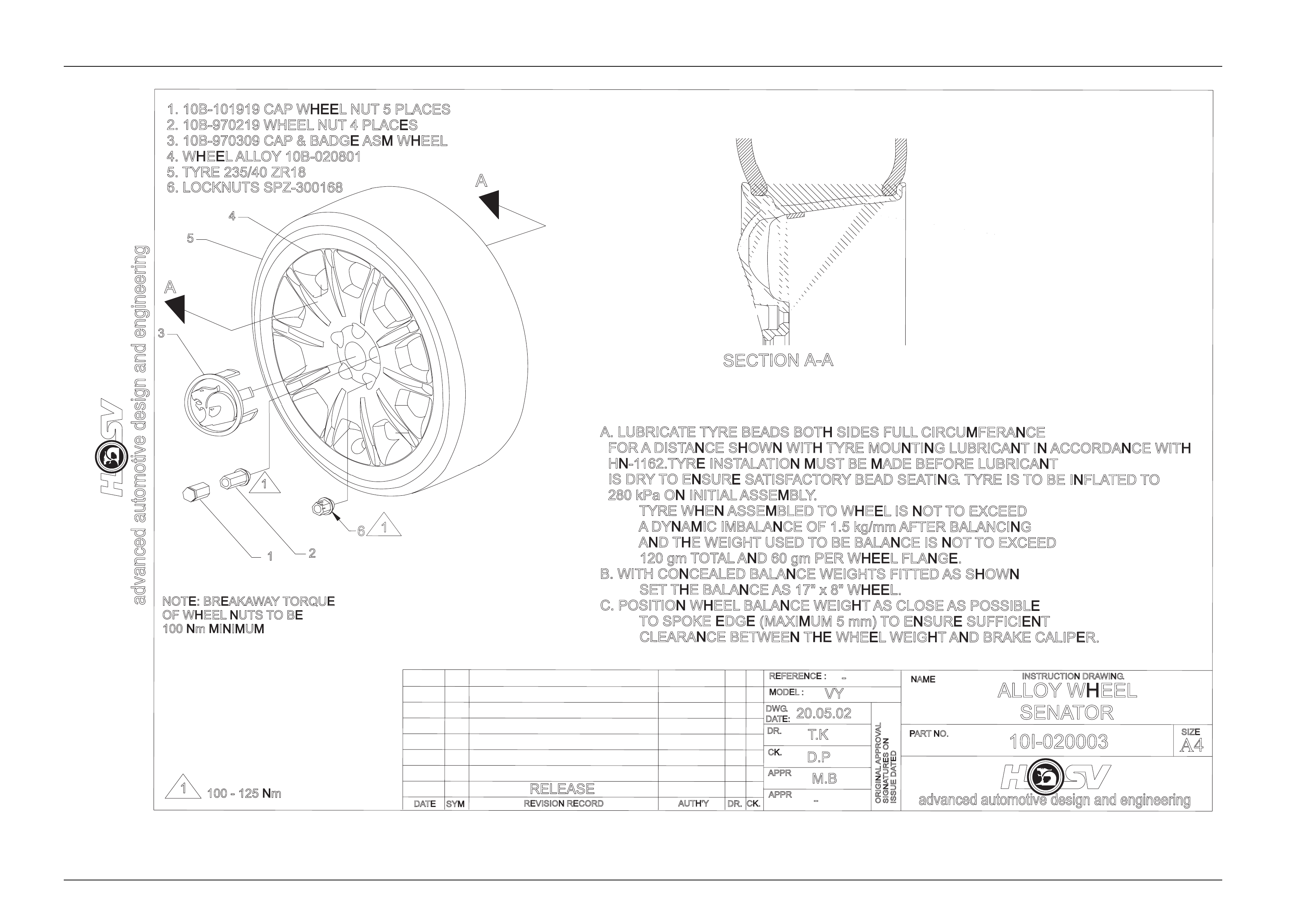
SET THE BALANCE AS 17" x 8" WHEEL.
C. POSITION WHEEL BALANCE WEIGHT AS CLOSE AS POSSIBLE
TO SPOKE EDGE (MAXIMUM 5 mm) TO ENSURE SUFFICIENT
CLEARANCE BETWEEN THE WHEEL WEIGHT AND BRAKE CALIPER.
1. 10B-101919 CAP WHEEL NUT 5 PLACES
2. 10B-970219 WHEEL NUT 4 PLACES
3. 10B-970309 CAP & BADGE ASM WHEEL
4. WHEEL ALLOY 10B-020801
5. TYRE 235/40 ZR18
1
2
1
3
4
5
A
A
6. LOCKNUTS SPZ-300168
61
Wheels, Tyres And Steering Wheel Page H-9
Page H-9
100 - 125 Nm
NOTE: BREAKAWAYTORQUE
OF WHEEL NUTS TOBE
100 Nm MINIMUM
SEC A-A
RELEASE
1M.B
VY
T.K
D.P
20.05.02
10I-020005
-
ALLOY WHEEL
SENATOR - 19"
-
A. LUBRICATE TYRE BEADS BOTH SIDES FULL CIRCUMFERANCE
FOR ADISTANCE SHOWN WITH TYRE MOUNTING LUBRICANT IN ACCORDANCE WITH
HN-1162.TYRE INSTALATION MUST BE MADE BEFORE LUBRICANT
IS DRYTO ENSURE SATISFACTORYBEAD SEATING.TYRE IS TO BE INFLATED TO
280 kPa ON INITIAL ASSEMBLY
.
TYRE WHEN ASSEMBLED TO WHEEL IS NOT TO EXCEED
ADYNAMIC IMBALANCE OF 1.5 kg/mm AFTER BALANCING
AND THE WEIGHT USED TO BE BALANCE IS NOT TO EXCEED
120 gm TOTAL AND 60 gm PER WHEEL FLANGE.
B. WITH CONCEALED BALANCE WEIGHTS FITTED AS SHOWN
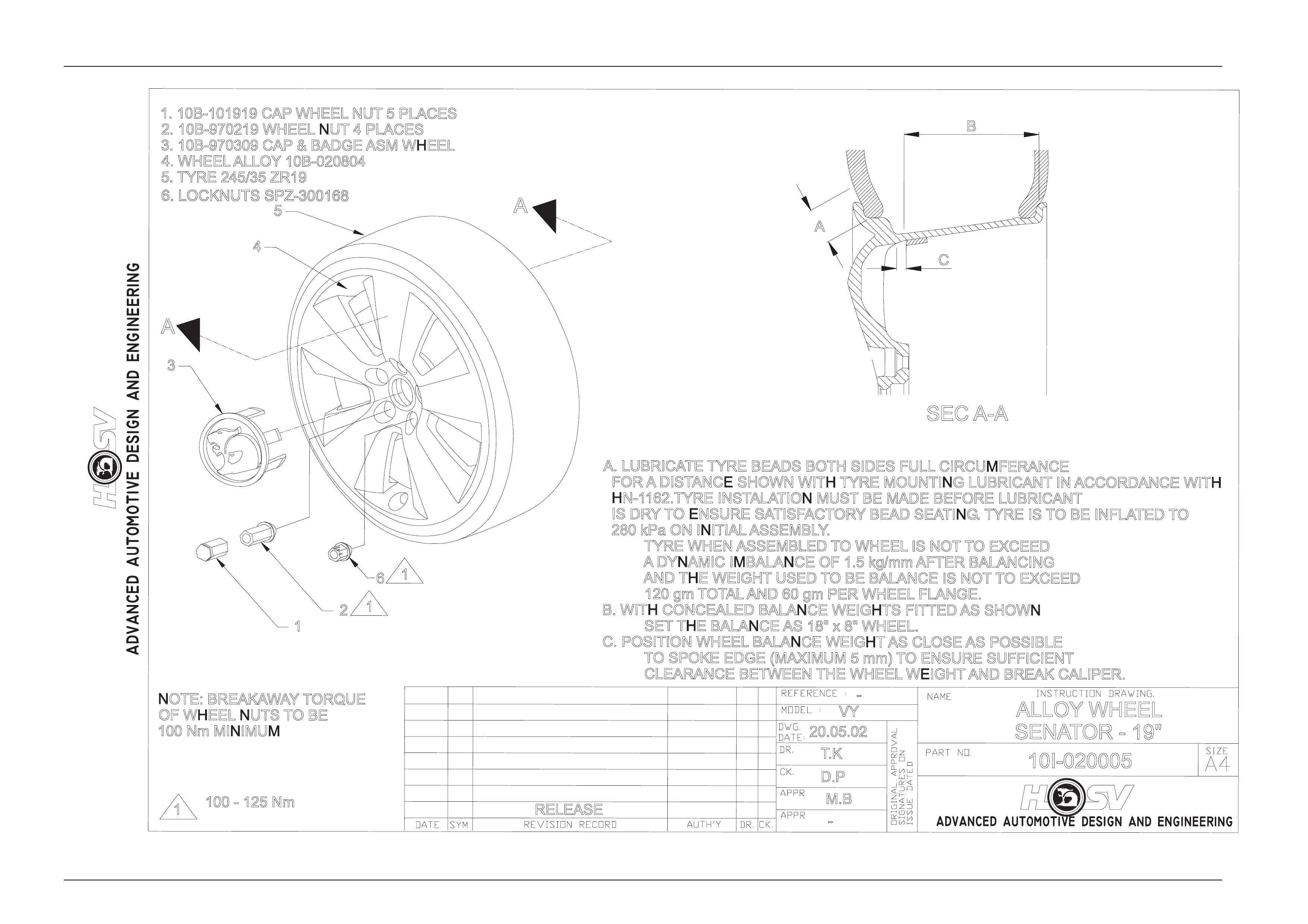
SET THE BALANCE AS 18" x 8" WHEEL.
C. POSITION WHEEL BALANCE WEIGHT AS CLOSE AS POSSIBLE
TO SPOKE EDGE (MAXIMUM 5 mm) TO ENSURE SUFFICIENT
CLEARANCE BETWEEN THE WHEEL WEIGHT AND BREAK CALIPER.
1. 10B-101919 CAP WHEEL NUT 5 PLACES
2. 10B-970219 WHEEL NUT 4 PLACES
3. 10B-970309 CAP & BADGE ASM WHEEL
4. WHEEL ALLOY 10B-020804
5. TYRE 245/35 ZR19
2
6
1
1
3
4
5
A
A
B
A
C
6. LOCKNUTS SPZ-300168
1
Wheels, Tyres And Steering Wheel Page H-10
Page H-10
A. LUBRICATE TYRE BEADS BOTH SIDES FULL CIRCUMFERANCE
FOR ADISTANCE SHOWN WITH TYRE MOUNTING LUBRICANT IN ACCORDANCE WITH
HN-1162.TYRE INSTALATION MUST BE MADE BEFORE LUBRICANT
IS DRYTO ENSURE SATISFACTORYBEAD SEATING.TYRE IS TO BE INFLATED TO
280 kPa ON INITIAL ASSEMBLY
.
TYRE WHEN ASSEMBLED TO WHEEL IS NOT TO EXCEED
ADYNAMIC IMBALANCE OF 1.5 kg/mm AFTER BALANCING
AND THE WEIGHT USED TO BE BALANCE IS NOT TO EXCEED
120 gm TOTAL AND 60 gm PER WHEEL FLANGE.
B. WITH CONCEALED BALANCE WEIGHTS FITTED AS SHOWN
SET THE BALANCE AS 18" x 8" WHEEL.
C. POSITION WHEEL BALANCE WEIGHT AS CLOSE AS POSSIBLE
TO SPOKE EDGE (MAXIMUM 5 mm) TO ENSURE SUFFICIENT
CLEARANCE BETWEEN THE WHEEL WEIGHT AND BRAKE CALIPER.
NOTE: BREAKAWAYTORQUE
OF WHEEL NUTS TOBE
100 Nm MINIMUM
100-125 Nm
1
BK
27.09.01
ALLOY WHEEL
GTS
SVW
10I-010002
SECA-A
A
C
B
A
A
4
5
3
2
6
1
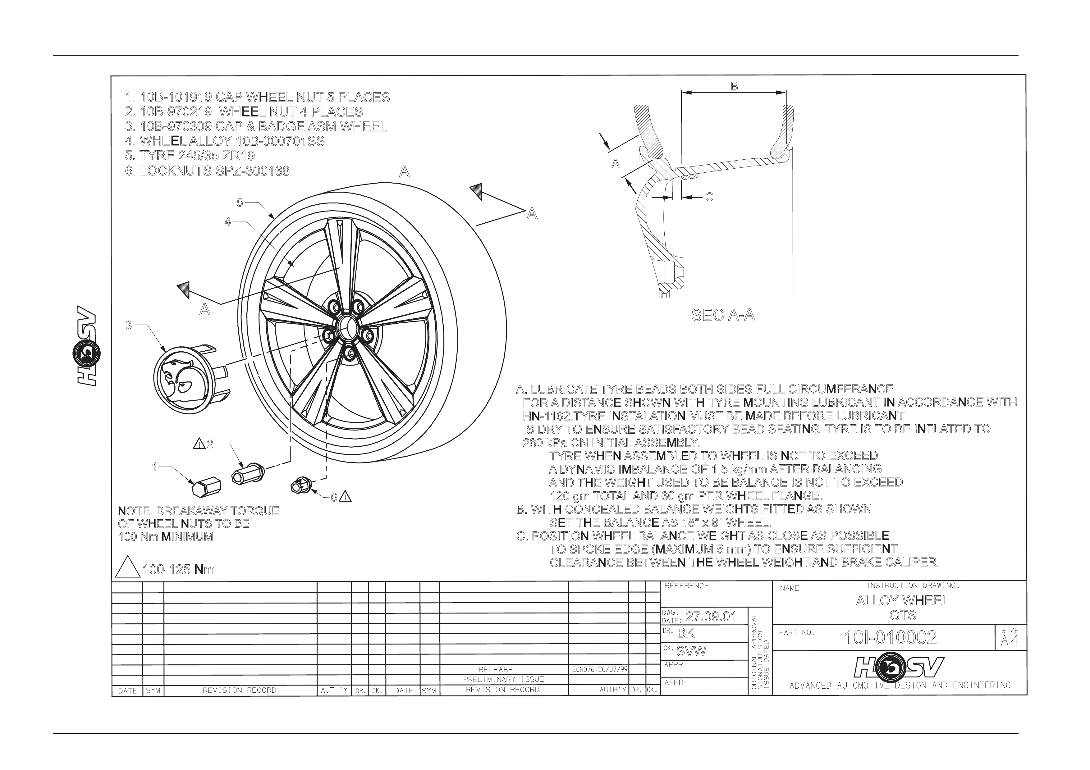
1. 10B-101919 CAP WHEEL NUT 5 PLACES
2. 10B-970219 WHEEL NUT 4 PLACES
3. 10B-970309 CAP & BADGE ASM WHEEL
4. WHEEL ALLOY 10B-000701SS
5. TYRE 245/35 ZR19
6. LOCKNUTS SPZ-300168
A

Wheels, Tyres And Steering Wheel Page H-11
Page H-11
3.3 Tyre Placard And Pressures
The HSV Tyre Placard is posit ioned on the opening of the right hand door. The Tyre Placard details important
information on the tyre pressures recomme nded for the HSV VYII Series Models. If carrying load, or travell ing
at high speed, the tyre pressures need to be increased as detailed on the placard. This is very important for
tyre wear and also to ensure that the tyres have sufficient load carrying capac ity.

Wheels, Tyres And Steering Wheel Page H-12
Page H-12
3.4 Loading The HSV Maloo
Also on the right hand door open ing are the HSV Maloo payload details. The Maloo is restricted to a maximum
payload of 490kg, with the driver and passenger in the car, this leaves approximately 350kg load capacity for
the rear tray. The load is restricted by the carr ying capacity of the 235/40 ZR18 t yres. As noted above, it is
important to increase tyre pressures when vehicle load is increased, refer to the tyre placard.

Wheels, Tyres And Steering Wheel Page H-13
Page H-13
3.5 HSV Temporary Spare Tyre
All HSV VYII Models are fitted with a temporary spare wheel/tyre. This temporary use spare is for emergency
use only, do not exceed 80km/h when it is fitted. Refer to the owner’s manual for further details.
All HSV Models fitted with the 19” wheel & tyre option are fitted with a space saver temporary spare wheel &
tyre.
This temporary spare is for emergency use only, do not exceed 80km/h when it is fitted. Refer to the owner’s
manual for further details.

Wheels, Tyres And Steering Wheel Page H-14
Page H-14
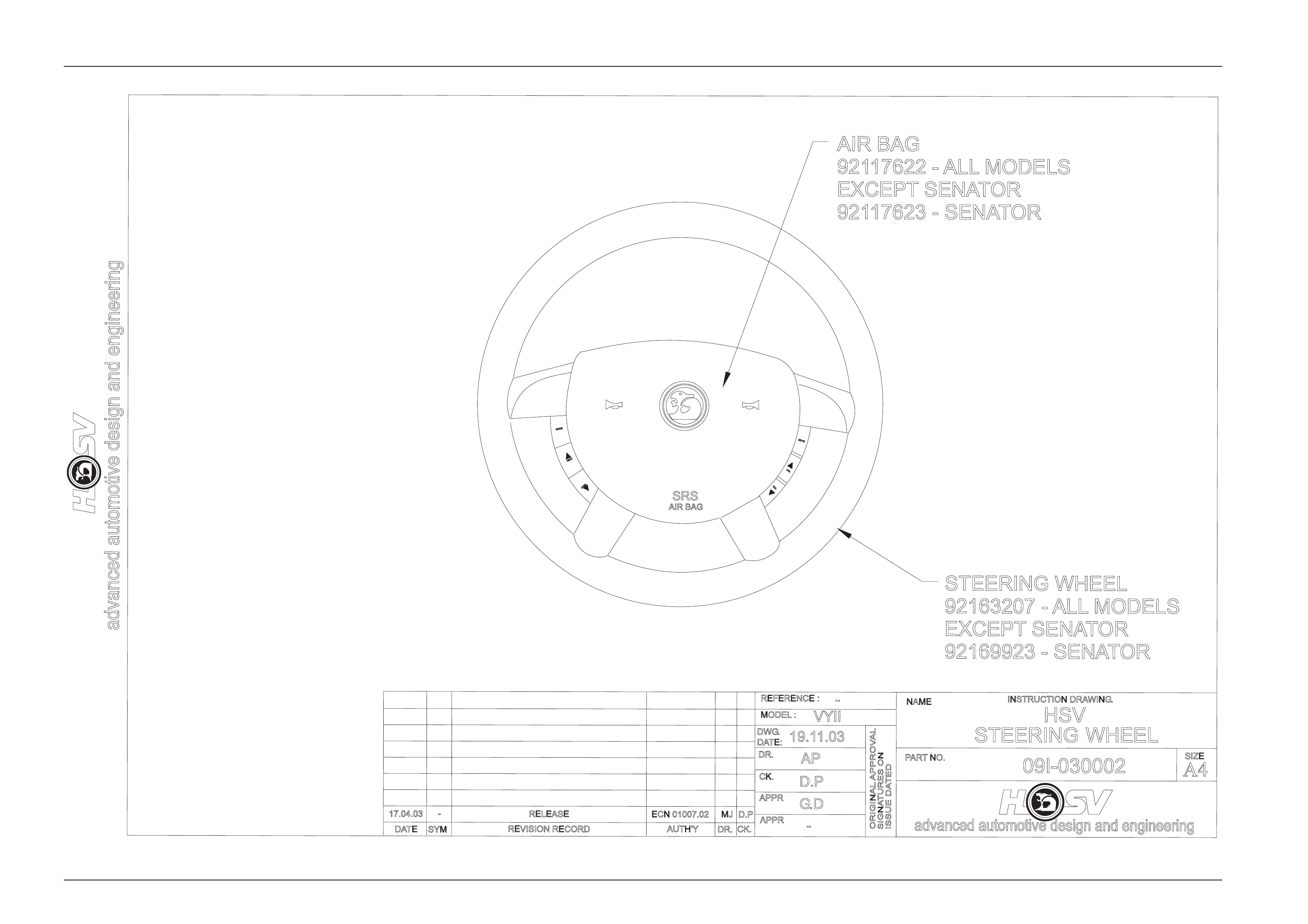
4 Steering Wheel
HSV VYII vehicles are equipped with AIR
BAGS. An AIR BAG is a Supplemental
Restraint System (SRS). Refer to CAUTIONS,
Section 12M, in Volume 12 of the Holden VYII
series Service Manual Supplement before
performing any service operation on or
around SRS components, the steering
mechanism or wiring. Failure to follow the
CAUTIONS could result in air bag
deployment, resulting in possible personal
injury or unnecessary SRS system repairs
The steering wheel assembly fitted to all HSV VYII models incorporates a HSV-design central horn pad complete with
HSV logo (see Drawing 09I-030002). The central horn pad also incorporates the driver’s-side air bag. All other
components, fixtures and fasteners are identical to standard Holden parts and therefore, any service operations on the
assembly should be carried out in accord ance with the relevant Holden Service Manual S upplement, refer to
Section 9A – STEERING of the VYII Series Service Information.
Wheels, Tyres And Steering Wheel Page H-15
Page H-15
advanced automotive design and engineering
DATE
PARTNO.
NAME
REVISION RECORD
SYM
ORIGINAL APPROVAL
ISSUE DATED
SIGNATURES ON
DR.
AUTH'YCK.
APPR
APPR
-
MODEL :
REFERENCE :
DWG.
CK.
DATE:
DR.
19.11.03
D.P
AP
VYII
-
HSV
STEERING WHEEL
09I-030002
advanced automotive design and engineering
INSTRUCTION DRAWING.
A4
SIZE
RELEASE
AIR BAG
92117622 - ALL MODELS
EXCEPT SENATOR
92117623 - SENATOR
STEERING WHEEL
92163207 - ALL MODELS
EXCEPT SENATOR
92169923 - SENATOR
SRS
AIR BAG
G.D
17.04.03 -ECN 01007.02 MJ D.P
VOL
VOL
MUTE
NEXT
NEXT
MODE