
Electrical And Instruments Page I-1
Page I-1
Section I
Electrical And Instruments
ATTENTION
HSV vehicles are equipped with a Supplemental Restraint System (SRS). An SRS consists of seat belt pre-
tensioners (fitted to all front seats), a dri ver’s side airbag, a passenger’s-side air ba g and left and rig ht hand side
air bags. Refer to CAUTIONS, Section 12M, in Volume 12 of the Holden VYII series Service Manual before
performing any service operation on or around SRS components, the steering mechanism or wiring. Failure to
follow the CAUTIONS could result in personal injury or unnecessary SRS system repairs.
1 Purpose................................................................................................................................................ I-2
2 Instrumentation ................................................................................................................................... I-3
2.1 General .................................................................................................................................................................I-3
2.2 Service Operations..............................................................................................................................................I-4
3 Electrical Facilities.............................................................................................................................. I-6
3.1 Gauge Binnacle (POD).........................................................................................................................................I-6
Oil Pressure..........................................................................................................................................................I-6
Battery Voltage....................................................................................................................................................-I-6
L.E.D. Interior Affect Lighting.............................................................................................................................I-9
4 HSV Fog Lamps................................................................................................................................. I-12
4.1 General ...............................................................................................................................................................I-12
4.2 Service Operation..............................................................................................................................................I-13
5 HSV High Intensity Discharge (HID) Xenon lights ......................................................................... I-14
5.1 General ...............................................................................................................................................................I-14
5.2 Specific...............................................................................................................................................................I-15
Techline
Electrical And Instruments Page- I-2
Page I-2
1 Purpose
The purpose of this s upplement is to provide information on the HSV e lectrical and instrument acc essories fitted to the HSV
VYII models. The information is designed to supplement that given in the Holden VYII series Service Manuals and details
are given where differences occur between the HSV models, and standar d Holden models. A series of instruction dra wings
describe the design changes and i ndicate specific part numbers, fitting instructions and relevant notes for vehicle servicing.
NOTE:
If specific technical data on a HSV model is not
contained in this supplement, obtain data for that
model from the Holden VYII series Service Manual
Supplement. References are made throughout this
section to Holden Service Manuals, to assist in
providing information for specific service o perations.
When hoisting (or jacking) HSV models, ensure
that the lifting head of the hoist lifts on the
chassis before the arm of the hoist contacts the
side-skirt

Electrical And Instruments Page- I-3
Page I-3
2 Instrumentation
2.1 General
A special Instrument Cluster designed by HSV is fitted to all HSV VYII vehicles. The cluster includes a HSV speedometer
with an operating r ange extending to 260 km/h. T he cluster incorporates a white face, red needles and warning lights and,
when illuminated, white numerals and letters. The cluster also consists of 3 multifunction display windows. At key off the
centre window displays the model and build number of the vehicle. The center window displays the HSV logo at key on for a
short period.
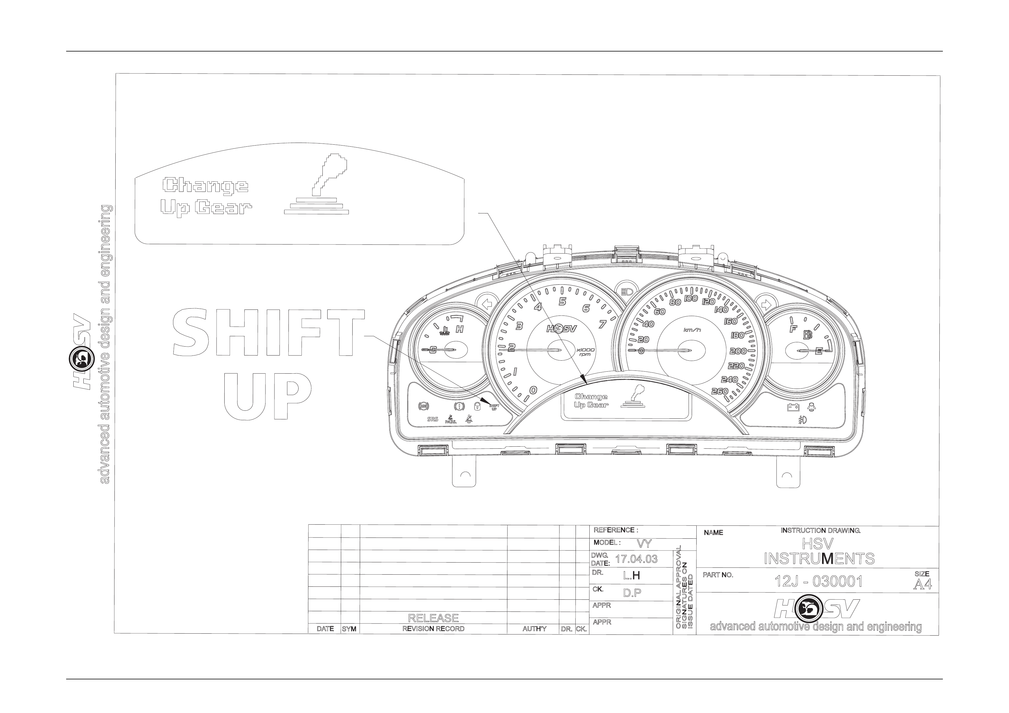
HSV manual vehicles are fitted with an upshift indicator. This indicator is controlled by the Engine Control Unit and a
Graphic on the Multi Function Display (MFD), in conjuction with an audible indicator and tell tale at the bottom LHS of the
instrument, gives the driver an indication of when to upshift to achieve maximum performance. The shift indicator will
operate:
GTS
All Other HSV
Models
1st 6,050 RPM 5,950 RPM
2nd 6,200 RPM 5,950 RPM
3rd 6,300 RPM 6,080 RPM
4th 6,300 RPM 6,100 RPM
5th 6,300 RPM 6,100 RPM
For details on graphic appearance see Drawing 12J-030001.
Electrical And Instruments Page I-4
Page I-4
advanced automotive design and engineering
DATE
PARTNO.
NAME
REVISION RECORD
SYM
ORIGINAL APPROVAL
ISSUE DATED
SIGNATURES ON
DR.
AUTH'YCK.
APPR
APPR
MODEL :
REFERENCE :
DWG.
CK.
DATE:
DR.
17.04.03
D.P
L.H
VY
HSV
INSTRUMENTS
12J - 030001
advanced automotive design and engineering
INSTRUCTION DRAWING.
A4
SIZE
RELEASE

Electrical And Instruments Page I-5
Page I-5
2.2 Service Operations
The HSV instrument cluster and the standar d Holden VYII cluster use the same mounting fixtures and f asteners. Remove,
service and refit the HSV instrument cluster in accordance with the proc edures detailed in the VYII Series Service
Information, refer to Section 12C – Instruments.

Electrical And Instruments Page- I-6
Page I-6
3 Electrical Facilities
The various special HSV opti ons fitted to the VYII range of vehicl es often require that sp ecial or additi onal e lectric har nesses
be installed. Some of these HSV harnesses are fitted during vehicle build-up at the Holden factory and other smaller
harnesses (often called ‘a patch harness’) are fitted at the HSV facility when the electrical option is being installed. A
summary of these electrical harnesses is includ ed to facilitate service, repair and retro-fitment of the HSV options.
PART No DESCRIPTION
92081965 Harness ASM – Body Wiring
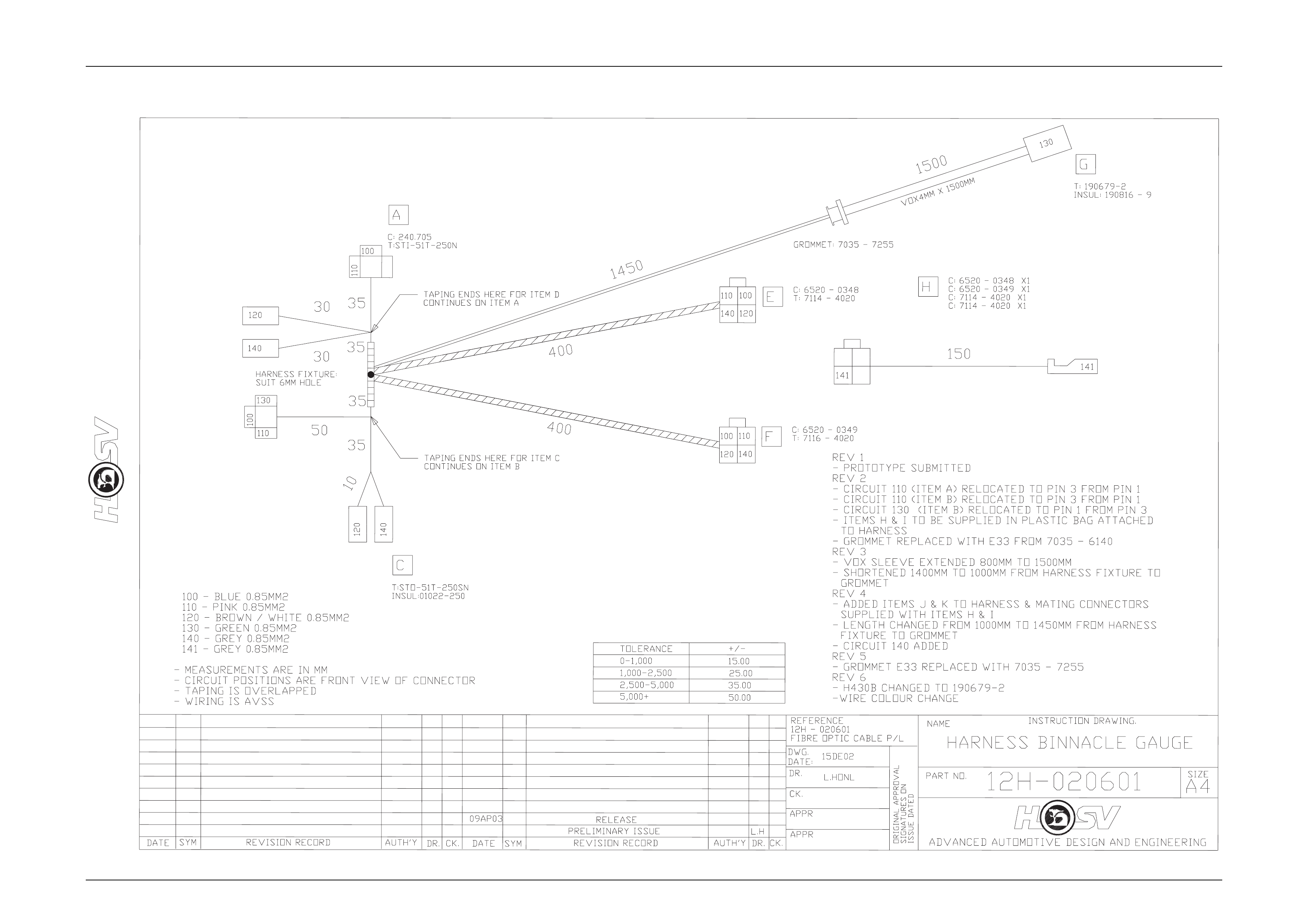
12H-020601 Harness – VY Binnacle Gauges
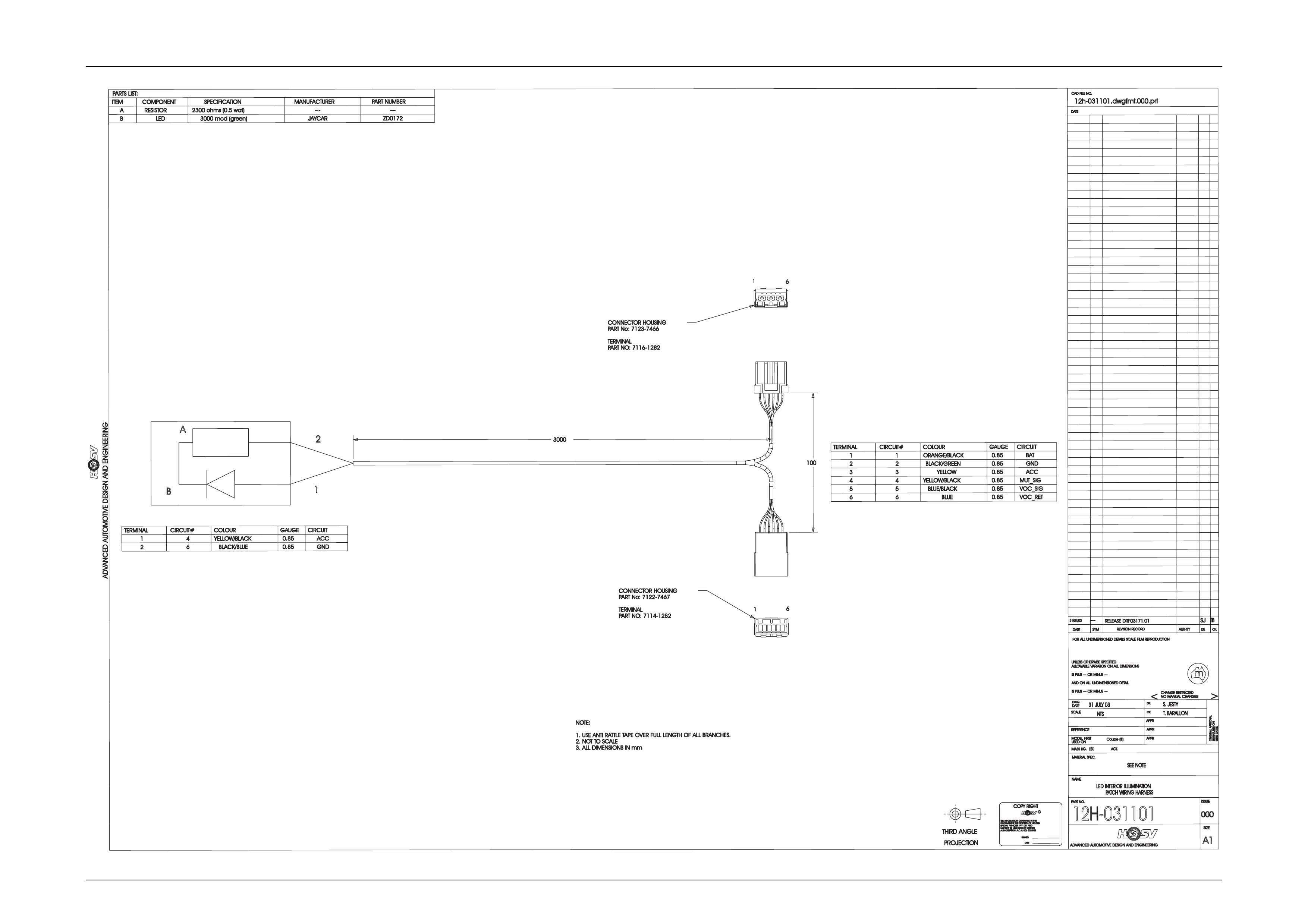
12H-031101 Harness – VYII L.E.D. Affect Light
12H-032703 Harness – VYII Rear Entertainment System.
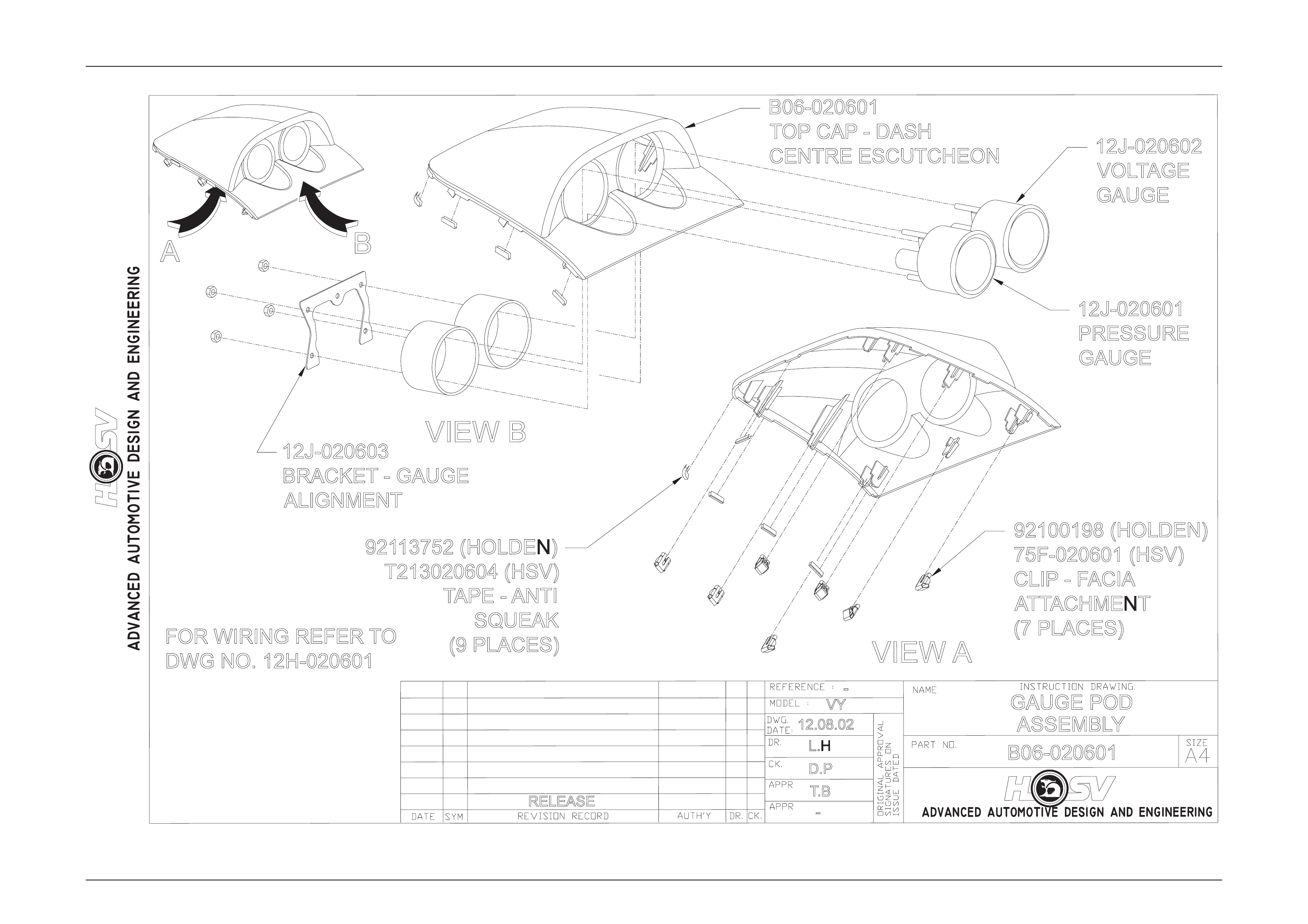
3.1 Gauge Binnacle (POD)
HSV vehicles, except Clubsport and Mal oo, are fitted with a gauge binnacle POD which houses an oil pressure gau ge and
battery voltage gauge.
Refer to Drawing B06-020601 and 12H-020601.
Oil Pressure
The oil pressure gauge takes i t’s reading from a Ω180 resistive to ground sender. At OKPa the sender shou ld read approx
10Ω across the sender terminal to ground. At 500 kPa the s ender should read 180 acros s the sender terminal to ground.
The (Gauge POD) harness circuits are as follows.
Battery Voltage
The battery voltage is taken from the accessories circuit. The gauge should read battery voltage when the key is in IGN
position.
Electrical And Instruments Page I-7
Page I-7
B
VIEW B
12J-020601
PRESSURE
GAUGE
12J-020602
VOLTAGE
GAUGE
B06-020601
TOP CAP - DASH
CENTRE ESCUTCHEON
12J-020603
BRACKET - GAUGE
ALIGNMENT
92113752 (HOLDEN)
T213020604 (HSV)
TAPE - ANTI
SQUEAK
(9 PLACES)
92100198 (HOLDEN)
75F-020601 (HSV)
CLIP -F
ACIA
ATTACHMENT
(7 PLACES)
FOR WIRING REFER TO
DWG NO. 12H-020601
-
B06-020601
GAUGE POD
ASSEMBLY
RELEASE -
L.H
D.P
T.B
12.08.02
VY
VIEW A
A
Electrical And Instruments Page- I-8
Page I-8

Electrical And Instruments Page I-9
Page I-9
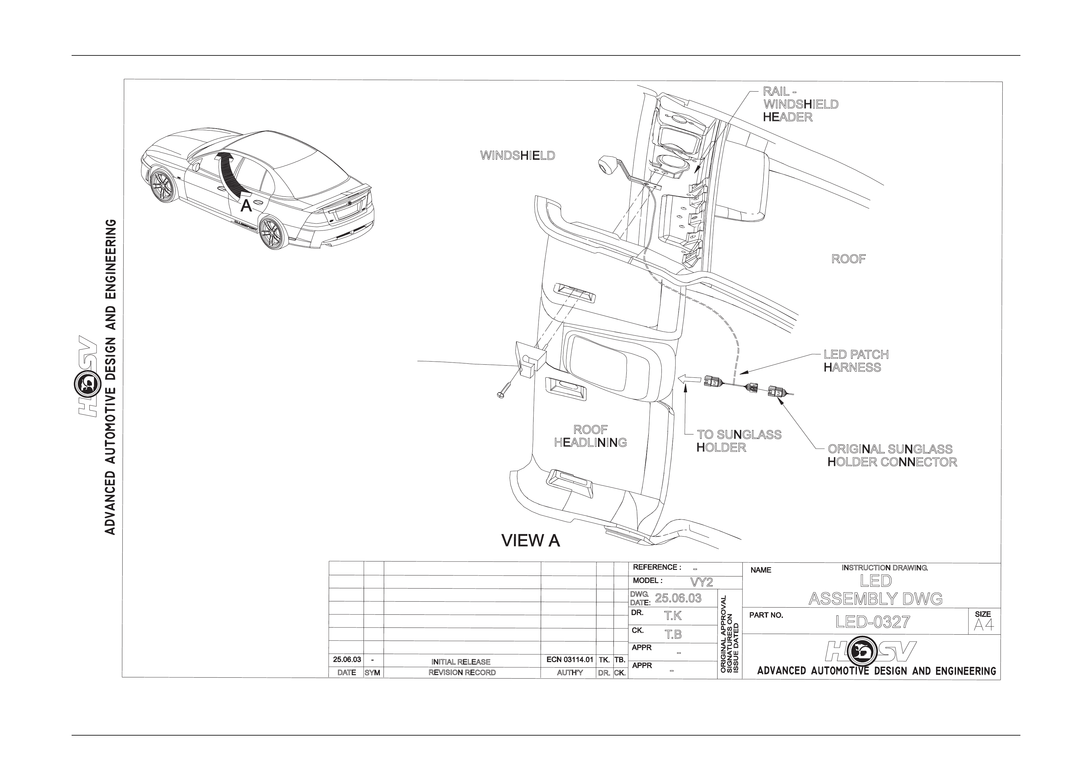
L.E.D. Interior Affect Lighting
An L.E.D. is fitted as an option to some VYII HSV vehicles.
The L.E.D. is housed in a small plastic bezel that is heat staked to a bracket. The bracket is mounted bet wee n the left hand
sun-visor hook and the sheet metal of the vehicle.
The L.E.D. should tun on when the vehicle is unlock ed using the remote key FOB and extinguish 10 seconds after the car is
locked.
The L.E.D. is an effect light that is supposed to give a dim wash of light across the centre console and left side of the
dashboard. It is NOT a reading or courtesy lamp.
The L.E.D. is not a serviceable item and should be replace d if damag ed. An electrical representation is given under the
drawing labelled LED-0327
Electrical And Instruments Page I-10
Page I-10
REVISION RECORD
SYM
DATE
INSTRUCTION DRAWING.
-
AUTH'YCK.
DR.
-
VY2
T.K
T.B
25.06.03
DWG.
DATE:
LED-0327
-LED
ASSEMBLYDWG
INITIAL RELEASE
ROOF
HEADLINING
WINDSHIELD
RAIL -
WINDSHIELD
HEADER
ROOF
TO SUNGLASS
HOLDER ORIGINAL SUNGLASS
HOLDER CONNECTOR
LED PATCH
HARNESS
Electrical And Instruments Page- I-11
Page I-11
2
4
BLACK/GREEN
VOC_RET
30.85
BLUE
VOC_SIG
3
COLOUR
MUT_SIG
YELLOW
5
0.85
6
0.85
YELLOW/BLACK
6
4
BLUE/BLACK
5
ACC
0.85
RELEASED
RF03171.01
UNLESSO
THERWISES
PECIFIED
m
AUTH'TY
A1
APPR
>
AUTHORISATIONA.C.N.0
068
020
53
DWG.
THIRDA
NGLE
SYM
S. JESTY
NOM
ANUALC
HANGES
SPECIALVEHICLESPTYL
TDAND
12h-031101.dwgfmt.000.prt
REFERENCE
SIGNATURESO
N
12H-031101
ANDO
NA
LLU
NDIMENSIONEDD
ETAIL
MATERIALS
PEC.
CK.
31 JULY03
SEE NOTE
THEI
NFORMATIONC
ONTAINEDI
NT
HIS
FORA
LLU
NDIMENSIONEDD
ETAILSS
CALEF
ILMR
EPRODUCTION
DR.
DATE
ADVANCED AUTOMOTIVE DESIGN AND ENGINEERING
NAME
C
ADVANCED AUTOMOTIVE DESIGN AND ENGINEERING
APPR
SIZE
DATE
SIGNED
CK.
31/07/03
PARTN
O.
LED INTERIOR ILLUMINATION
PATCH WIRING HARNESS
APPR
NTS
COPYR
IGHT
USEDO
N
<
MAYN
OTB
EU
SEDWITHOUTW
RITTEN
PROJECTION
SCALE
ISSUEDATED
T. BARALLON
DATE
ISSUE
ISP
LUS-
--O
RM
INUS-
--
MASSK
G.E
ST.A
CT.
CHANGER
ESTRICTED
DOCUMENTI
ST
HEP
ROPERTYOFH
OLDEN
DR.
ALLOWABLEV
ARIATIONO
NA
LLD
IMENSIONS
MODELF
IRST
ORIGINALAPPROVAL
000
ISP
LUS-
--O
RM
INUS-
--
REVISIONR
ECORD
CAD FILE NO.
DATE
--- SJ
0.85 BAT
GND
1
CIRCUIT#
0.85
CIRCUIT
ORANGE/BLACK
1
TERMINAL GAUGE
2
CONNECTOR HOUSING
PART No: 7123-7466
TERMINAL
PART NO: 7116-1282
CONNECTOR HOUSING
PART No: 7122-7467
TERMINAL
PART NO: 7114-1282
100
3000
16
6
1
NOTE:
1. USE ANTI RATTLE TAPE OVER FULL LENGTH OF ALL BRANCHES.
2. NOTT
O SCALE
3. ALL DIMENSIONS IN mm
Coupe(
III)
TB
ACC
ITEM SPECIFICATION
COMPONENT
COLOUR
2300 ohms (0.5 wat)
PART NUMBER
2
1
CIRCUIT#
JAYCAR
TERMINAL
B
0.85
A
GAUGE
PARTS LIST:
6
BZD0172
4
---
A
CIRCUIT
YELLOW/BLACK
---
3000 mcd (green)
0.85
RESISTOR
1
MANUFACTURER
BLACK/BLUE GND
LED
2

Electrical And Instruments Page I-12
Page I-12
4 HSV Fog Lamps
4.1 General
HSV Fog lamps are fitted directly to the front fascia of all HSV VY models. The HSV lamps use a glass convex reflector to
provide a wide-angle b eam concentrated in a range of 30 to 40 metres in front of the lamp. The external lense incorporates
a clear horizontal section.
Fog Lamps should be only used in adverse weather conditions i.e. fog. Use of fog lamps on hot sunny days may result in
failure from overheating. These are not daylight running lights.

Electrical And Instruments Page- I-13
Page I-13
4.2 Service Operation
No periodic servicing of the HSV lamps is required. Globes may be replaced b y rem oving a water-tight access cover on
the rear of the lamp, unclip the two spring clips which retain the globe carrier at the focal point of the reflector. Remove the
globe and wire assembly from the seal, discard globe and replac e with a new 12 Volt, 55 Watt H3 Globe assembly.
Replacement fog lamps available through HSV are identifie d as follows
12C-020601 LAMP FOG – CLUBSPORT/GTS/MALOO
12C-020901 LAMP FOG - SENATOR
NOTE:
Condensation may appear on the lense of the fog
lamp when appropriate ambient conditions exist.
This condensation will clear as the ambient
conditions change or after four or five minutes
operation of the fog lamps

Electrical And Instruments Page- I-14
Page I-14
5 HSV High Intensity Discharge
(HID) Xenon lights
5.1 General
VY11 HSV vehicles may be option ed with HID Driving Lights. These HID lights are located in the Fog lamp position on the
front fascia.
NOTE
HID Lights operate at quite high voltage levels, so all
care must be taken when removing front fascia for
service or repair. Please refer to Service/Owners
manual and take note of warnings in e ngine bay.
HID lights are designed only to operate when high beam is activated. i.e. when indicator stalk is pul led toward (flashed) or
pushed back to operate high beams. They are not a fog light and should not be used in any other manner, other than
described above.
HID Lights offer a brilliant white light that will illumi nate above and beyond a standard ‘High Beam’ system. All care must be
taken when using or adjusting these lights, as they can dazzle the op erator.
The HID lights, ballasts and looms are not serviceable items and should be replaced if damaged.

Electrical And Instruments Page- I-15
Page I-15
5.2 Specific
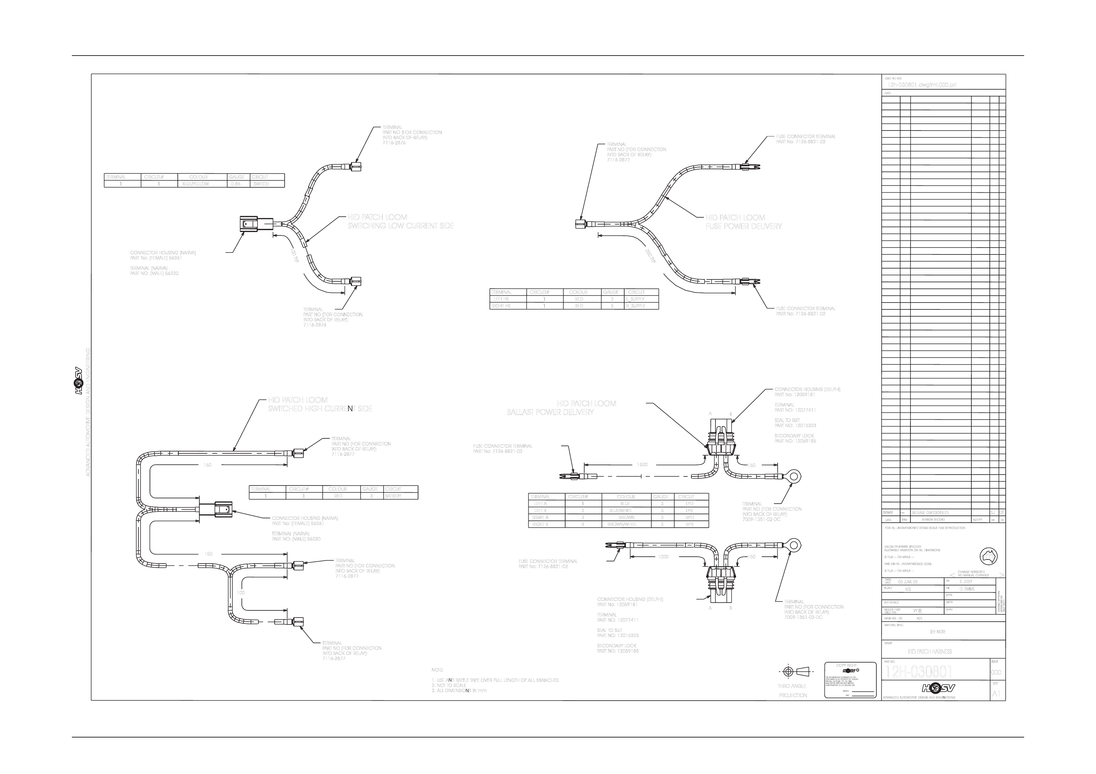
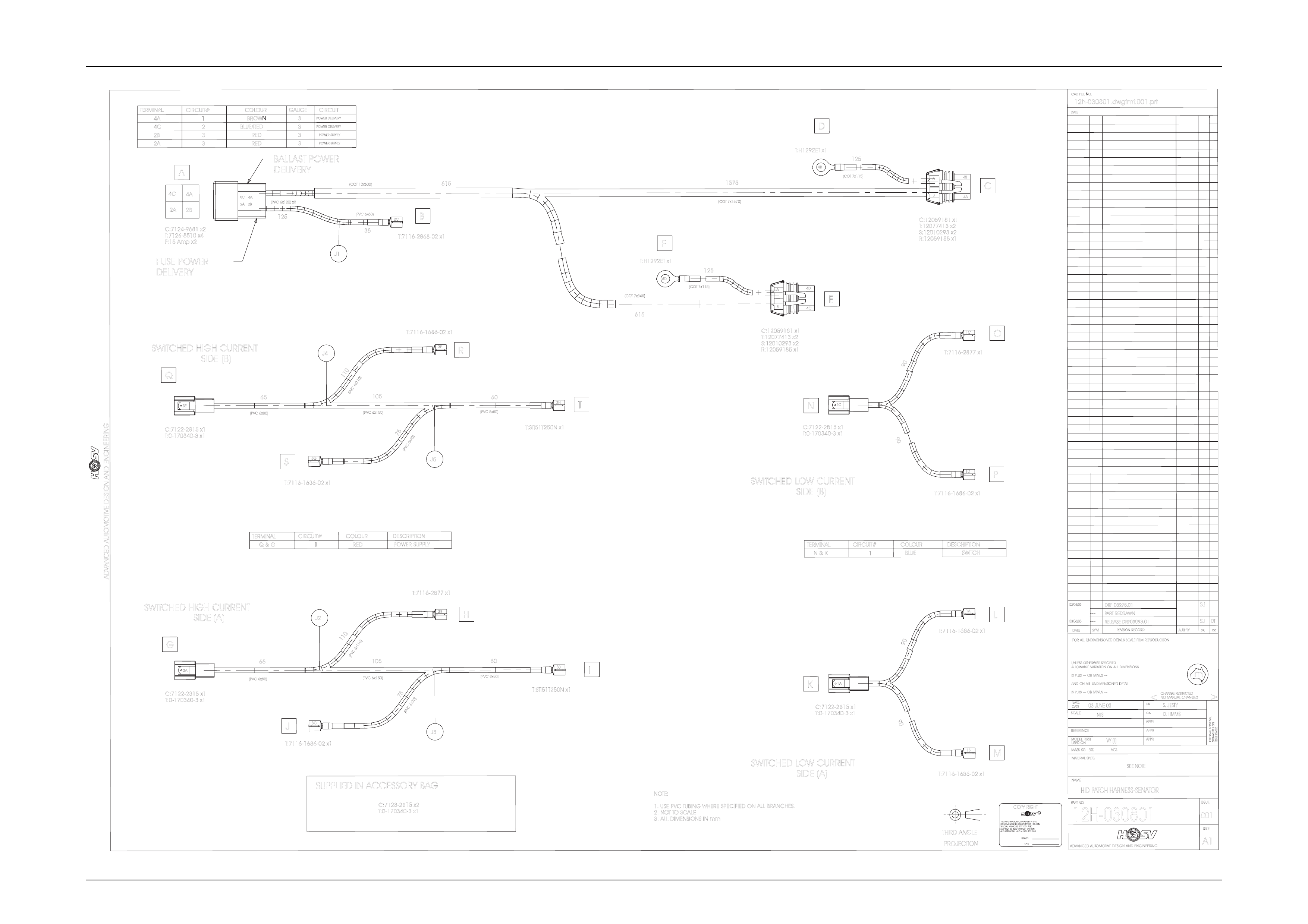
HID Lights use a separate patch harness that taps into the high beam activation circuit, these looms also provide power to
the HID ballasts. The looms have drawing numbers – Senator: 12H-030801 and Clubsport: 12H-030608. Fuses for the HID
lights are located next to fuse box in engine bay and are labeled Left Hand LH HID and Right Hand RH HID.
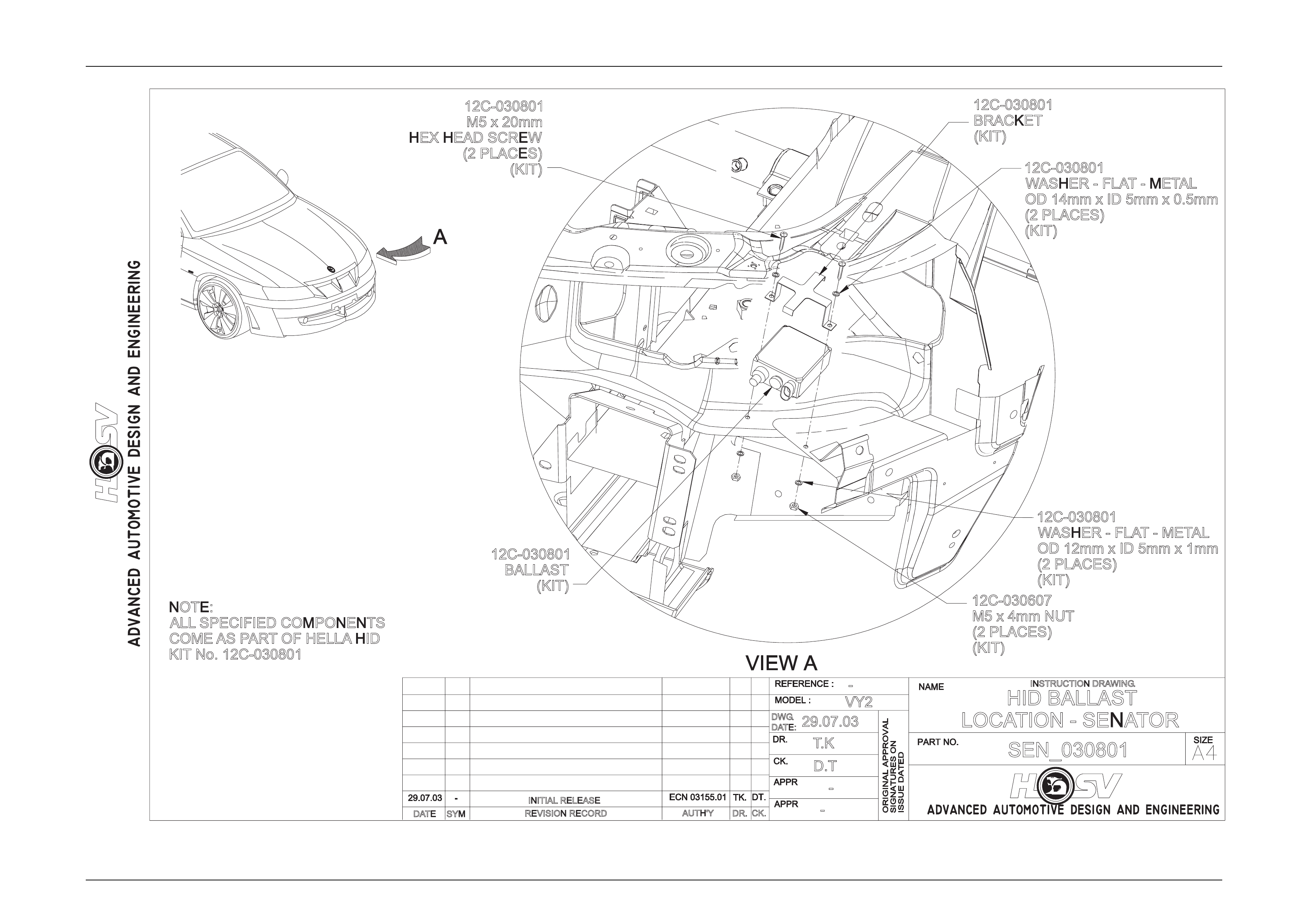
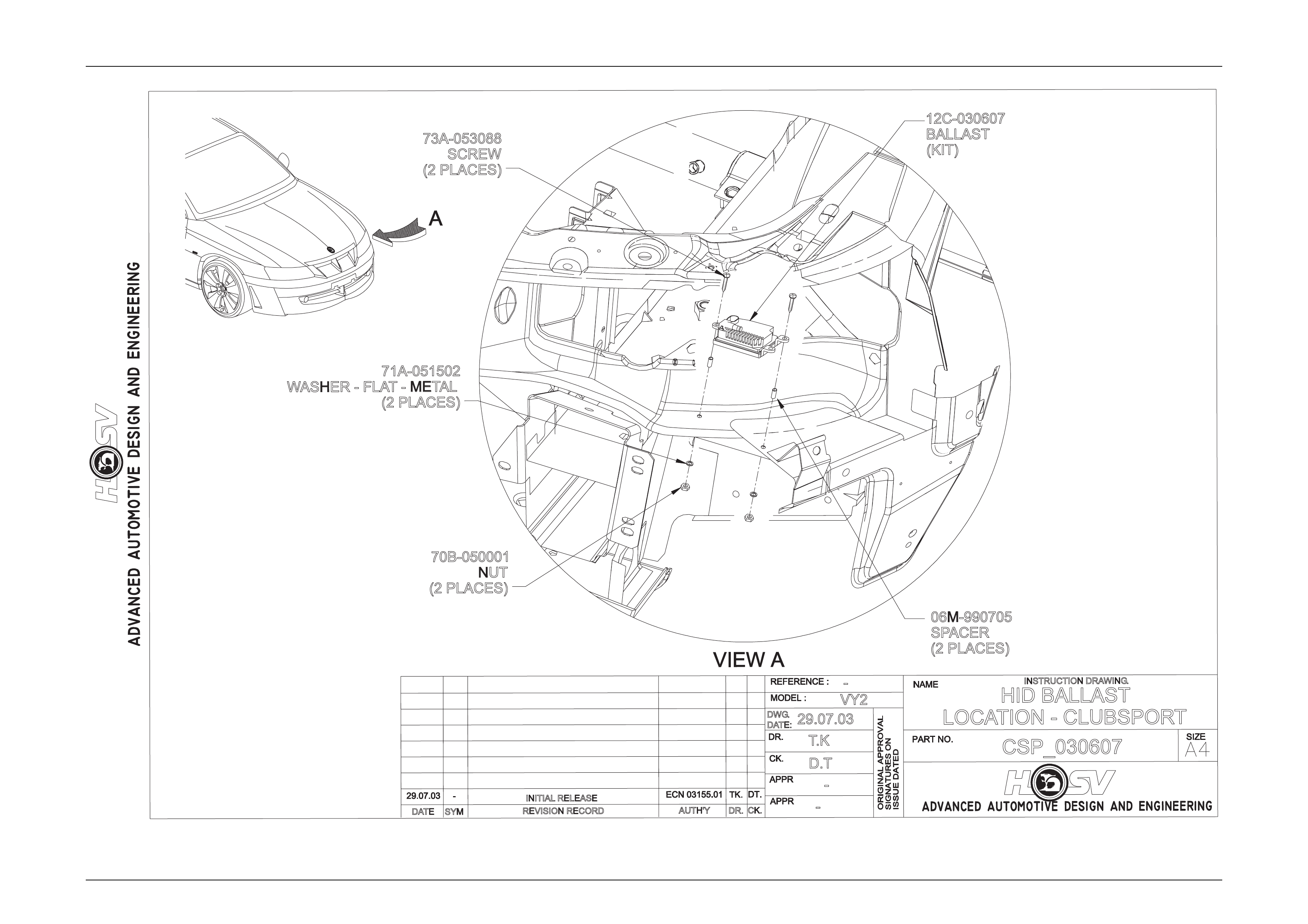
Ballasts are located under the headlights, attached to the sheet metal of vehicle, as per instruction drawing
Senator: SEN_030801 and C lubsport: CSP_030607. These ball asts power up the globes.
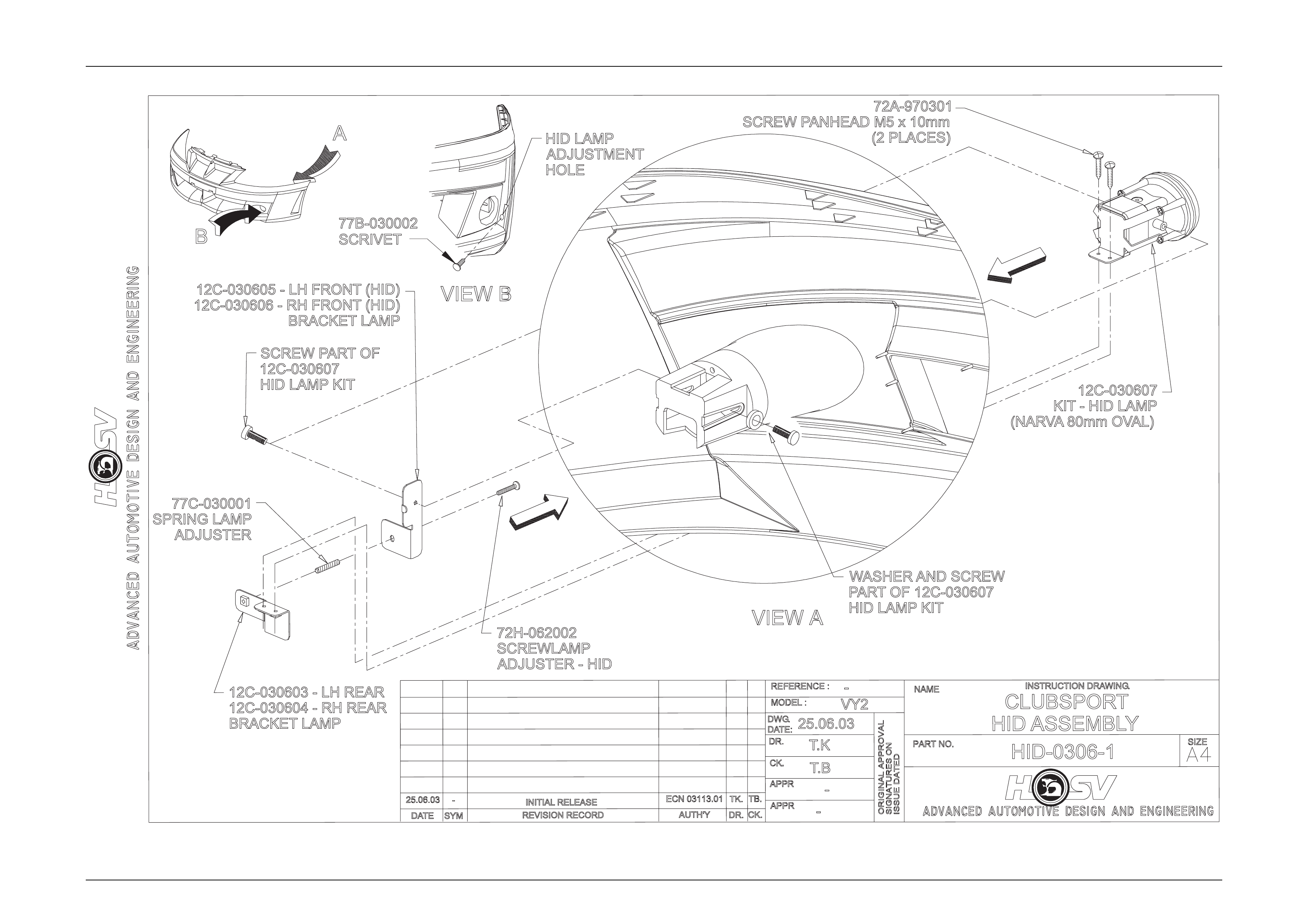
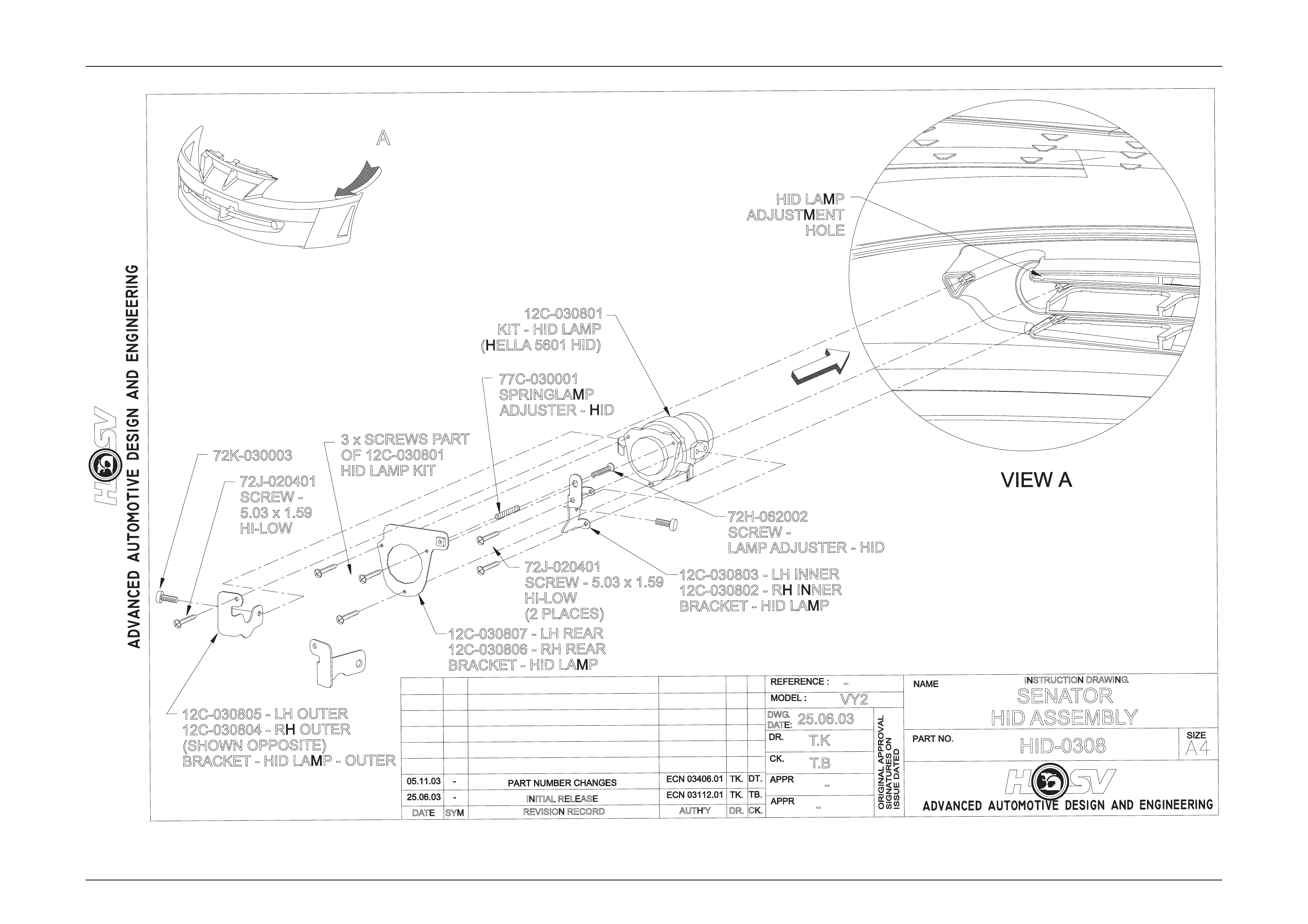
HID Globes are located in front fascia below headlights. They consist of a HID Bulb, Lens, Brackets and adjusting
equipment, all containe d within the Fog light position. Instruction drawing n umbers – Se nator: HID-0308 and
Clubsport: HID-0306-1
Electrical And Instruments Page I-16
Page I-16
REVISION RECORD
SYM
DATE
INSTRUCTION DRAWING.
-
AUTH'Y CK.
DR.
-
VY2
T.K
T.B
25.06.03
DWG.
DATE:
HID-0306-1
-
CLUBSPORT
HID ASSEMBLY
INITIAL RELEASE
A
77C-030001
SPRING LAMP
ADJUSTER
12C-030603 - LH REAR
12C-030604 - RH REAR
BRACKET LAMP
12C-030605 - LH FRONT (HID)
12C-030606 - RH FRONT (HID)
BRACKET LAMP
72H-062002
SCREWLAMP
ADJUSTER - HID
72A-970301
77B-030002
SCRIVET
SCREW PANHEAD M5 x 10mm
(2 PLACES)
12C-030607
KIT - HID LAMP
(NARVA80mm OVAL)
WASHER AND SCREW
PARTOF 12C-030607
HID LAMP KIT
SCREW PARTOF
12C-030607
HID LAMP KIT
B
HID LAMP
ADJUSTMENT
HOLE
Electrical And Instruments Page- I-17
Page I-17
REVISION RECORD
SYM
DATE
INSTRUCTION DRAWING.
-
AUTH'YCK.
DR.
-
VY2
T.K
T.B
25.06.03
DWG.
DATE:
HID-0308
-
SENATOR
HID ASSEMBLY
INITIAL RELEASE
A
12C-030805 - LH OUTER
12C-030804 - RH OUTER
(SHOWNO
PPOSITE)
BRACKET - HID LAMP -O
UTER
12C-030801
KIT - HID LAMP
(HELLA 5601 HID)
72H-062002
SCREW -
LAMP ADJUSTER - HID
12C-030803 - LH INNER
12C-030802 - RH INNER
BRACKET - HID LAMP
77C-030001
SPRINGLAMP
ADJUSTER - HID
12C-030807 - LH REAR
12C-030806 - RH REAR
BRACKET - HID LAMP
3 x SCREWS PART
OF 12C-030801
HID LAMP KIT
72J-020401
SCREW - 5.03 x 1.59
HI-LOW
(2 PLACES)
72J-020401
SCREW -
5.03 x 1.59
HI-LOW
HID LAMP
ADJUSTMENT
HOLE
72K-030003
Electrical And Instruments Page- I-18
Page I-18
REVISION RECORD
SYM
DATE
INSTRUCTION DRAWING.
-
AUTH'Y CK.
DR.
-
VY2
T.K
D.T
29.07.03
DWG.
DATE:
SEN_030801
-HID BALLAST
LOCATION - SENATOR
INITIAL RELEASE
12C-030801
M5 x 20mm
HEX HEAD SCREW
(2 PLACES)
(KIT)
12C-030801
BALLAST
(KIT)
12C-030801
BRACKET
(KIT)
12C-030607
M5 x 4mm NUT
(2 PLACES)
(KIT)
12C-030801
WASHER - FLAT - METAL
OD 12mm x ID 5mm x 1mm
(2 PLACES)
(KIT)
12C-030801
WASHER - FLAT - METAL
OD 14mm x ID 5mm x 0.5mm
(2 PLACES)
(KIT)
NOTE:
ALL SPECIFIED COMPONENTS
COME AS PART OF HELLA HID
KIT No. 12C-030801
Electrical And Instruments Page- I-19
Page I-19
REVISION RECORD
SYM
DATE
INSTRUCTION DRAWING.
-
AUTH'YCK.
DR.
-
VY2
T.K
D.T
29.07.03
DWG.
DATE:
CSP_030607
-HID BALLAST
LOCATION - CLUBSPORT
INITIAL RELEASE
73A-053088
SCREW
(2 PLACES)
06M-990705
SPACER
(2 PLACES)
12C-030607
BALLAST
(KIT)
70B-050001
NUT
(2 PLACES)
71A-051502
WASHER - FLAT- METAL
(2 PLACES)
Electrical And Instruments Page- I-20
Page I-20
RELEASED
RF03093.01
UNLESSO
THERWISES
PECIFIED
m
AUTH'TY
A1
APPR
>
AUTHORISATIONA.C.N.006802053
DWG.
THIRDA
NGLE
SYM
S. JESTY
NOMANUALC
HANGES
SPECIALVEHICLESPTYLTDAND
12h-030801.dwgfmt.000.prt
REFERENCE
SIGNATURESO
N
12H-030801
ANDO
NA
LLU
NDIMENSIONEDD
ETAIL
MATERIALS
PEC.
CK.
03 JUNE 03
SEE NOTE
THEINFORMATIONCONTAINEDINTHIS
FORA
LLU
NDIMENSIONEDD
ETAILSS
CALEF
ILMR
EPRODUCTION
DR.
DATE
ADVANCED AUTOMOTIVE DESIGN AND ENGINEERING
NAME
C
ADVANCED AUTOMOTIVE DESIGN AND ENGINEERING
APPR
SIZE
DATE
SIGNED
CK.
03/06/03
PARTN
O.
HID PATCH HARNESS
APPR
NTS
COPYR
IGHT
USEDO
N
<
MAYNOTBEUSEDWITHOUTWRITTEN
PROJECTION
SCALE
ISSUED
ATED
D. TIMMS
DATE
ISSUE
IS PLUS-
--O
RM
INUS-
--
MASSK
G.E
ST.A
CT.
CHANGER
ESTRICTED
DOCUMENTISTHEPROPERTYOFHOLDEN
DR.
ALLOWABLEV
ARIATIONO
NA
LLD
IMENSIONS
MODELF
IRST
ORIGINALA
PPROVAL
000
IS PLUS-
--O
RM
INUS-
--
REVISIONR
ECORD
CAD FILE NO.
DATE
--- SJ
NOTE:
1. USE ANTI RATTLE TAPE OVER FULL LENGTH OF ALL BRANCHES.
2. NOTT
OSCALE
3. ALL DIMENSIONS IN mm
VY(
II)
DT
CONNECTOR HOUSING (NARVA)
PART No: (FEMALE) 56261
TERMINAL (NARVA)
PART NO: (MALE) 56220
CIRCUIT
CIRCUIT#
TERMINAL GAUGE
COLOUR
3BATTERY
1RED
1
TERMINAL
PART NO (FOR CONNECTION
INTOBACK OF RELAY):
7116-2877
HID PATCH LOOM
SWITCHED HIGH CURRENT SIDE
CONNECTOR HOUSING (NARVA)
PART No: (FEMALE) 56261
TERMINAL (NARVA)
PART NO: (MALE) 56220
TERMINAL
PART NO (FOR CONNECTION
INTOBACK OF RELAY):
7116-2876
TERMINAL
PART NO (FOR CONNECTION
INTOBACK OF RELAY):
7116-2876
CIRCUIT#
TERMINAL
11
CIRCUIT
GAUGE
0.85 SWITCH
BLUE/YELLOW
COLOUR
HID PATCH LOOM
SWITCHING LOW CURRENT SIDE
100TYP
250TYP
CIRCUIT#
TERMINAL
LEFT HS 1
CIRCUIT
GAUGE
3L_SUPPLY
RED
COLOUR
RIGHT HS 1RED 3R_SUPPLY
FUSE CONNECTOR TERMINAL
PART No: 7126-8821-02
FUSE CONNECTOR TERMINAL
PART No: 7126-8821-02
1500 150
1000 150
TERMINAL
LEFT A
LEFT B
1
CIRCUIT
GAUGE
3LPD
BLUE
COLOUR
2BLUE/WHITE 3LPR
CIRCUIT#
RIGHT A3BROWN 3RPD
RIGHT B4BROWN/WHITE 3RPR
FUSE CONNECTOR TERMINAL
PART No: 7126-8821-02
FUSE CONNECTOR TERMINAL
PART No: 7126-8821-02
CONNECTOR HOUSING (DELPHI)
PART No: 12059181
TERMINAL
PART NO: 12077411
SEAL TOSUIT
PART NO: 12015323
SECONDARY LOCK
PART NO: 12059185
CONNECTOR HOUSING (DELPHI)
PART No: 12059181
TERMINAL
PART NO: 12077411
SEAL TOSUIT
PART NO: 12015323
SECONDARY LOCK
PART NO: 12059185
A
A
B
B
HID PATCH LOOM
FUSE POWER DELIVERY
HID PATCH LOOM
BALLAST POWER DELIVERY
TERMINAL
PART NO (FOR CONNECTION
INTOBACK OF RELAY):
7116-2877
TERMINAL
PART NO (FOR CONNECTION
INTOBACK OF RELAY):
7116-2877
150
150
100
TERMINAL
PART NO (FOR CONNECTION
INTOBACK OF RELAY):
7009-1351-02-DC
TERMINAL
PART NO (FOR CONNECTION
INTOBACK OF RELAY):
7116-2877
TERMINAL
PART NO (FOR CONNECTION
INTOBACK OF RELAY):
7009-1351-02-DC
Electrical And Instruments Page- I-21
Page I-21
RELEASED
RF03093.01
UNLESSO
THERWISES
PECIFIED
m
AUTH'TY
A1
APPR
>
AUTHORISATIONA.C.N.006802053
DWG.
THIRDA
NGLE
SYM
S. JESTY
NOM
ANUALC
HANGES
SPECIALVEHICLESPTYLTDAND
12h-030801.dwgfmt.001.prt
REFERENCE
SIGNATURESO
N
12H-030801
ANDO
NA
LLU
NDIMENSIONEDD
ETAIL
MATERIALS
PEC.
CK.
03 JUNE 03
SEE NOTE
THEINFORMATIONCONTAINEDINTHIS
FORA
LLU
NDIMENSIONEDD
ETAILSS
CALEF
ILMR
EPRODUCTION
DR.
DATE
ADVANCED AUTOMOTIVE DESIGN AND ENGINEERING
NAME
C
ADVANCED AUTOMOTIVE DESIGN AND ENGINEERING
APPR
SIZE
DATE
SIGNED
CK.
03/06/03
PARTN
O.
HID PATCH HARNESS-SENATOR
APPR
NTS
COPYR
IGHT
USEDO
N
<
MAYNOTBEUSEDWITHOUTWRITTEN
PROJECTION
SCALE
ISSUED
ATED
D. TIMMS
DATE
ISSUE
ISP
LUS-
--O
RM
INUS-
--
MASSK
G.E
ST.ACT.
CHANGER
ESTRICTED
DOCUMENTISTHEPROPERTYOFH
OLDEN
DR.
ALLOWABLEV
ARIATIONO
NA
LLD
IMENSIONS
MODELF
IRST
ORIGINALA
PPROVAL
001
ISP
LUS-
--O
RM
INUS-
--
REVISIONR
ECORD
CAD FILE NO.
DATE
--- SJ
NOTE:
1. USE PVC TUBING WHERE SPECIFIED ON ALL BRANCHES.
2. NOTT
OSCALE
3. ALL DIMENSIONS IN mm
VY(
II)
DT
BALLAST POWER
DELIVERY
FUSE POWER
DELIVERY
(PVC 6x120) x2
(COT 10x600)
(PVC 6x60)
615
C:7124-9681 x2
T:7126-8510 x4
F:15 Amp x2
C:7122-2815 x1
T:0-170340-3 x1
C:7122-2815 x1
T:0-170340-3 x1
SWITCHED HIGH CURRENT
SIDE (B)
SWITCHED HIGH CURRENT
SIDE (A)
SWITCHED LOW CURRENT
SIDE (A)
SWITCHED LOW CURRENT
SIDE (B)
125
35
4C 4A
2A 2B
A
Q
G
B
R
S
H
J
T
I
65
65
(PVC 6x80)
(PVC 6x80)
3E
3A
T:7116-2868-02 x1
T:7116-1686-02 x1
T:7116-1686-02 x1
2C
3F
3H
3G
3C
3B
3D
T:STI51T250N x1
T:STI51T250N x1
105
105
60
60
(PVC 6x150)
(PVC 6x150)
(PVC 8x50)
(PVC 8x50)
110
110
75
75
(PVC6x110)
(PVC6x110)
(PVC6x70)
(PVC6x70)
J1
J4
J5
J2
J3
T:7116-2877 x1
T:7116-1686-02 x1
C:12059181 x1
T:12077413 x2
S:12010293 x2
R:12059185 x1
C:12059181 x1
T:12077413 x2
S:12010293 x2
R:12059185 x1
A
B
4B
4A
4D
4C
A
B
C
E
D
F
T:H1292ET x1
T:H1292ET x1
4B
4D
1575
125
615
(COT 7x1570)
(COT 7x345)
(COT 7x115)
(COT 7x115)
125
N
K
O
P
L
M
90
90
90
90
C:7122-2815 x1
T:0-170340-3 x1
C:7122-2815 x1
T:0-170340-3 x1
T:7116-2877 x1
T:7116-1686-02 x1
T:7116-1686-02 x1
T:7116-1686-02 x1
1A
1A
1B
1C
1C
1D
PARTR
EDRAWN
---
03/06/03
DRF0
3275.01
SJ
3
3
POWER DELIVERY
CIRCUIT#
3
1
3
CIRCUIT
BLUE/RED
3
3
RED
BROWN
2
RED
GAUGE
COLOUR
2B
TERMINAL
4C
4A
2A
POWER DELIVERY
POWER SUPPLY
POWER SUPPLY
CIRCUIT#
1POWER SUPPLY
RED
DESCRIPTION
COLOUR
TERMINAL
Q&G CIRCUIT#
1
TERMINAL
N&K BLUE
COLOUR
SWITCH
DESCRIPTION
SUPPLIED IN ACCESSORY BAG
C:7123-2815 x2
T:0-170340-3 x1
4C 4A
2A 2B