
Options And Accessories Page J-1
Page J-1
Section J
Options And Accessories
ATTENTION
HSV vehicles are equipped with a Supplemental Restraint System (SRS). An SRS consists of seat belt pre-
tensioners (fitted to all front seats), a driver’s-side air bag, a passenger’s-side air bag and left and right side air
bags. Refer to CAUTIONS, Section 12M, in Volume 12 of th e Holden VYII series Ser vice Manu al before performing
any service operation on or around SRS components, the steering mechanism or wiring. Failure to follow the
CAUTIONS could result in personal injury or unnecessary SRS system repairs.
1 Purpose............................................................................................................................................... J-2
2 HSV Sunroof ....................................................................................................................................... J-3
3 Fire Extinguisher................................................................................................................................ J-4
3.1 General ................................................................................................................................................................J-4
3.2 Service Operations.............................................................................................................................................J-7
4 HSV Specific Body Control Modules................................................................................................ J-8
4.1 Changing BCM’s.................................................................................................................................................J-8
5 HSV Embedded Security System...................................................................................................... J-9
5.1 General ................................................................................................................................................................J-9
5.2 Linking the ESS to a new BCM at the Retailer – BCM In Warranty...............................................................J-10
5.3 Linking the ESS to a new BCM at the Retailer – BCM out of Warranty........................................................J-11
5.4 Key Programming Mode...................................................................................................................................J-12
Programming Extra Keys to the Vehicle.........................................................................................................J-12
Programming All New Key...............................................................................................................................J-12
5.5 Link Enable Procedure.....................................................................................................................................J-13
5.6 Service Operations...........................................................................................................................................J-14
6 Electrochromic Mirrors.................................................................................................................... J-19
6.1 General ..............................................................................................................................................................J-19
7 HSV Rear Entertainment System.................................................................................................... J-20
7.1 General ..............................................................................................................................................................J-20
7.2 HSV DVD Entertainment System.....................................................................................................................J-37
System, Warranty And Procedures Information ............................................................................................J-37
Options And Accessories Page J-2
Page J-2
1 Purpose
The purpose of this supplement is to provide information on the special options and accessories fitted to the HSV VYII
models. This information is designed to supplement that contained in the Holden VYII series Service Manuals, and details
are given where differences occur between the HSV models and standar d Holden models. A series of instruction drawings
detail the design changes a nd indicate specific part number s , fitting instructions an d relevant notes for vehicle servicing.
NOTE
If specific technical data on a HSV model is not
contained in this supplement, obtain data for that
model from the relevant Holden VYII series Service
Manual Supplement. References are made
throughout this section to Holden Service M anuals, to
assist in providing information for specific service
operations.
When hoisting (or jacking) HSV models, ensure
that the lifting head of the hoist lifts on the
chassis before the arm of the hoist contacts the
side-skirt


Options And Accessories Page J-4
Page J-4
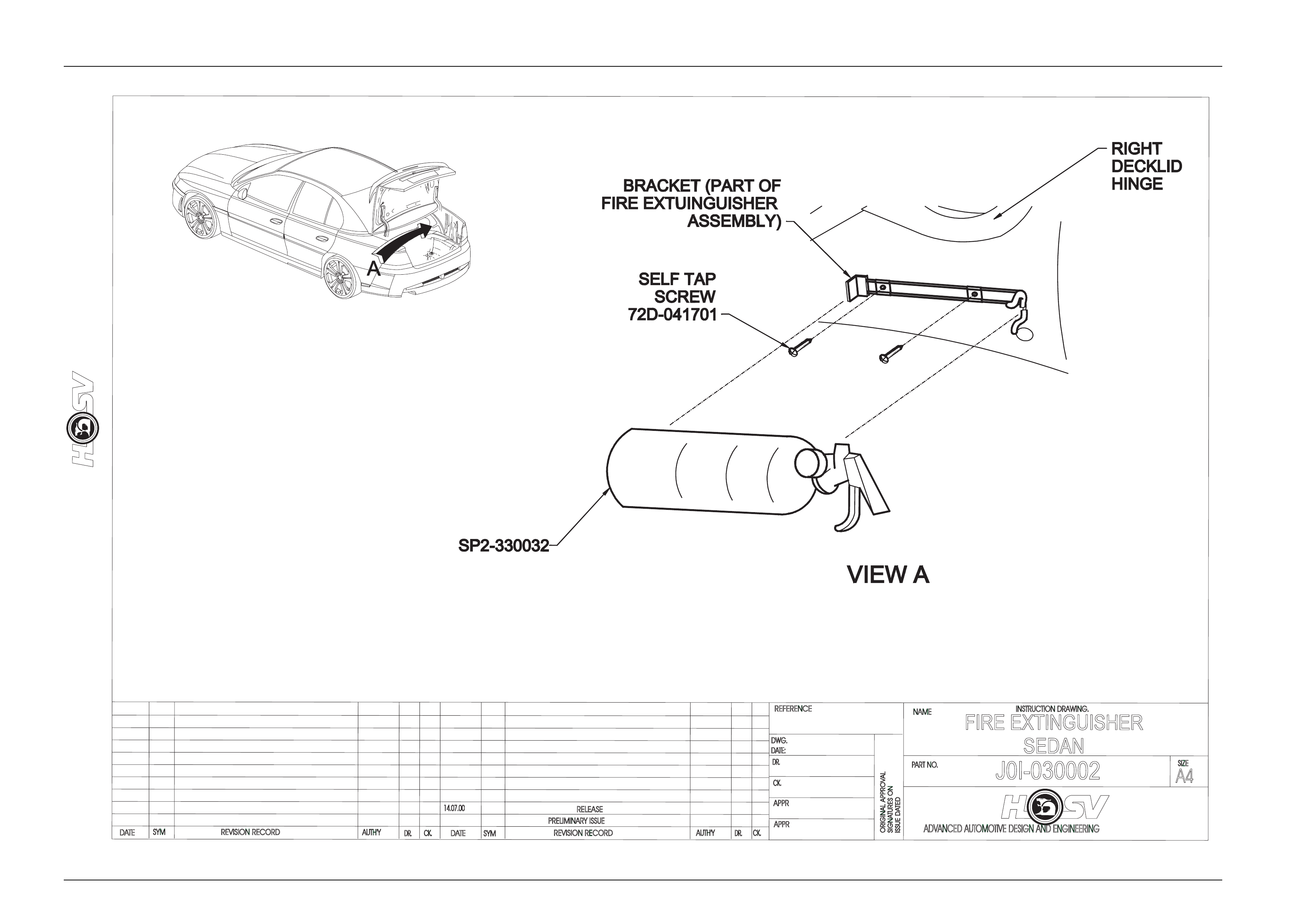
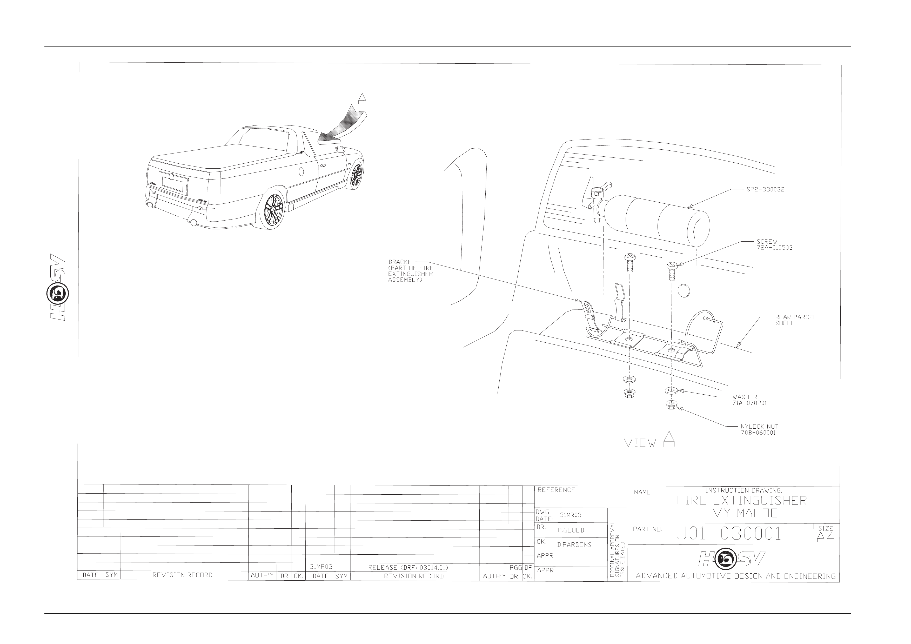
3 Fire Extinguisher
3.1 General
HSV VYII models are fitted with a HSV design fire extinguisher. The extinguisher is located in the re ar luggage
compartment for sedan models.(Refer to drawing J0I-030002) For Maloo the extinguisher is located on the right
hand side of the rear parcel shelf, refer to drawing J0I-030001.
Options And Accessories Page J-5
Page J-5
DATE
ISSUE DATED
AUTH'Y
CK.
SYM
AUTH'Y
RELEASE
REVISION RECORD
DATE
SYM
SIGNATURES ON
ORIGINAL APPROVAL
DR.
14.07.00
ADVANCED AUTOMOTIVE DESIGN AND ENGINEERING
J0I-030002
INSTRUCTION DRAWING.
A4
SIZE
FIRE EXTINGUISHER
SEDAN
REVISION RECORD
PRELIMINARY ISSUE
CK.
NAME
PART NO.
CK.
REFERENCE
DWG.
DR.
DATE:
APPR
APPR
DR.
07.11.03
AP
DP
BRN
Options And Accessories Page J-6
Page J-6

Options And Accessories Page J-7
Page J-7
3.2 Service Operations
The fire extinguisher should be subjected to a regular visual inspection in accordance with the instructions on the
extinguisher. Particularly, the extinguisher should be inspected for dama ge and to ensure that the integral pressure
gauge registers the appropri ate internal pressure. When discharged or when the internal pressure is ou tside the
prescribed limits, the extinguishers should be serviced and re-charged by an appropriate supplier. New extinguishers
are available through the HSV spare parts systems.

Options And Accessories Page J-8
Page J-8
4 HSV Specific Body Control
Modules
4.1 Changing BCM’s
• If the BCM is changed Refer to HSV Embedded Security System, Section 5.2 or Section 5.3 in the Holden Special
Vehicles Service Manual Sup plement.
• If extra or new keys are required Refer to HSV Embedded Security System, Section 5.4 in the Holden Special
Vehicles Service Manual Sup plement.

Options And Accessories Page J-9
Page J-9
5 HSV Embedded Security System
5.1 General
The new HSV Embedded Security System (ESS) is fitted as standard equipment to all HSV VTII, WH, VYII and WK
model Vehicles. The ESS is a microprocessor-controlled immobiliser, which automatically interrupts essential electrical
circuits when in “armed mode”. The ESS st ores the BCM’s security code and when the car is started it reads this code
from the SCI bus. If this code is different from the stored one the ESS ent ers armed mode and prevents the vehic le from
starting.

Options And Accessories Page J-10
Page J-10
5.2 Linking the ESS to a new BCM at the
Retailer – BCM In Warranty
If the BCM requires replacement within the BCM warranty period, the Retailer sha ll be supp lied with a replacement B CM
programmed with the same BCM security code as the original BCM. In this case, the replacement BCM and new keys
are simply fitted to the vehicle. No ESS specific requireme nts are needed.

Options And Accessories Page J-11
Page J-11
5.3 Linking the ESS to a new BCM at the
Retailer – BCM out of Warranty
When a BCM requires replacement outside the BCM warranty period the Retailer shall need to obtain a replacement
BCM and keys from Holden’s Service Parts Operation (HSPO). The replacement BCM and Keys will not contain the
same BCM Security Code as the original BCM.
When a new BCM with different BCM security code is fitted to the vehicle, the Retailer will have to d o the following:
• Program a new key to the BCM.
• Link the BCM and PCM.
TECH 2 must be connected to the vehicle diagnostic connector whilst the key is being pr ogrammed and/or ESS is being
linked to the vehicle. The Link Enable Procedure is require d to be performed twice to allow an all new key to be
programmed and also allow the ESS learn to learn the BCM security code. The procedure for programming a new key to
a new BCM and linking the ESS to the vehicle is as follows:
1. Fit new BCM to the vehicle.
2. Ensure all doors, boot and bonnet are closed, all doors are unlocked, dome lamp is in the ‘doors’ position and the
radio, headlight and wash-wipe switches are off.
3. Place new key into the ignition barrel.
4. Turn ignition on. Verify ESS beeps 5 times.
5. F or VT.II / VX Vehicles TECH2 must be operating in the “ Normal Mode” submenu of the Body Control Modul e sub-
menu.
For VYII / WK Vehicles TECH2 must be operating in the Bod y Control Mod ule su b-menu only.
6. Perform the Link Enable Procedure (see Section 5.5). Wait 1 second between each lock unlock to ensure the door
lock actuators function correctly during this proced ure.
7. Verify that the ESS beeps twice. T ECH2 reports ignition is at 12Vdc. T he ESS has now entered “Key Programming
mode”.
8. Select Key Programming function – “All New Key” - from the security sub-menu in the body menu of the TECH2.
Enter BCM security code as requested by T ECH2. Complete key programming as requ ested by TECH2.
9. Turn ignition off and wait for 2 seconds. Turn ignition on.
10. Verify ESS beeps 5 times. (At this stage the ESS is in “armed mode”).
11. For VT.II / VX Vehicles TECH2 must be operating in the “Normal Mode” subme nu of the Body Control Module sub-
menu.
For VYII / WK Vehicles TECH2 must be operating in the Bod y Control Mod ule su b-menu only.
12. Perform the Link Enable Procedure (see Section 5.5). Wait 1 second between each lock unlock to ensure the door
lock actuators function correctly during this proced ure.
13. Verify that the ESS beeps twice. TECH2 reports ignition is at 12Vdc.
14. Link the PCM to the BCM using TECH2. ESS beeps twice (ESS has now learned the BCM security code).
15. Turn ignition off. Wait until TECH2 pr ogramming is complete.
16. Turn ignition on.
17. Turn ignition off. Wait 2 seconds.
18. Turn ignition on.
19. Verify ESS beeps once. The ESS is now operating in “normal mode”.
20. Crank engine. Verify vehicle st arts as normal.

Options And Accessories Page J-12
Page J-12
5.4 Key Programming Mode
Once the ESS has been placed into key programming mode the ESS will behave as if in “sleep mode” for one ignition
cycle only. This allows for the one ignition cycle that is required to program a new key to a new or existing BCM. The
ESS will enter “normal mode” for the next ignition cycle. If the BCM is a new BCM in the vehicle with a new security
code, the ESS will then enter “armed mode” as expected.
Programming Extra Keys to the Vehicle
Programming more keys for the vehicle can be achieved using TECH2 once the ESS has been re-linked to the vehicle
as described as follo ws:
1. Ensure all doors, boot and bonnet are closed, all doors are unlocked, dome lamp is in the ‘doors’ position and the
radio, headlight and wash-wipe switches are off.
2. Place new key into the ignition barrel.
3. Turn ignition on. Verify ESS beeps 5 times.
4. F or VT.II / VX Vehicles TECH2 must be operating in the “ Normal Mode” submenu of the Body Control Modul e sub-
menu.
For VYII / WK Vehicles TECH2 must be operating in the Bod y Control Mod ule su b-menu only.
5. Perform the Link Enable Procedure (see Section 5.5). Wait 1 second between each lock unlock to ensure the door
lock actuators function correctly during this proced ure.
6. Verify that the ESS beeps twice. T ECH2 reports ignition is at 12Vdc. T he ESS has now entered “Key Programming
mode”.
7. Select Key Programming function – “Extra Key” - from the security sub-menu in the body menu of the TECH2.
When TECH2 requests ignition to be cycled with the existing key, leave the new key in the ignition barrel and
instead, press the unlock button on the existing key. Verify the ESS beeps once and the Theft Deterrent LED stops
flashing. Complete key programming as requested by TE CH2.
8. Turn ignition off and wait for 2 seconds.
9. Turn ignition on. Verify ESS beeps once. The ESS is now operating in “normal mode”.
10. Crank engine. Verify vehicle st arts as normal.
Programming All New Key
Programming an All New Key for the vehicle can be achieved by performing the following procedure:
1. Ensure all doors, boot and bonnet are closed, all doors are unlocked, dome lamp is in the ‘doors’ position and the
radio, headlight and wash-wipe switches are off.
2. Place new key into the ignition barrel.
3. Turn ignition on. Verify ESS beeps 5 times.
4. F or VT.II / VX Vehicles TECH2 must be operating in the “ Normal Mode” submenu of the Body Control Modul e sub-
menu.
For VYII / WK Vehicles TECH2 must be operating in the Body Control Mod ule su b-menu.
5. Perform the Link Enable Procedure (see Section 5.5). Wait 1 second between each lock unlock to ensure the door
lock actuators function correctly during this proced ure.
6. Verify that the ESS beeps twice. T ECH2 reports ignition is at 12Vdc. T he ESS has now entered “Key Programming
mode”.
7. Select Key Programming function – “All New Key” - from the security sub-menu in the body menu of the TECH2.
Enter BCM security code as requested by T ECH2. Complete key programming as requ ested by TECH2.
8. Turn ignition off and wait for 2 seconds.
9. Turn ignition on. Verify ESS beeps once and Theft Deterrent LED is off. The ESS is now operating in “normal mode”.
10. Crank engine. Verify vehicle st arts as normal.

Options And Accessories Page J-13
Page J-13
5.5 Link Enable Procedure
Each ESS has it’s own unique Link Enable C ode (LEC), programmed into each ESS by HSV. This code correspon ds to
a unique sequence of 10 vehicle bo dy functions comprising of the follo wing actions:
1. Drivers door. Open then Close
2. Drivers door Snib. Lock then Unlock
3. Wash-Wipe. On then off.
Approximately 60,000 link enable codes ar e available.
For the Link Enable Procedure contact Australian Arrow Pty Ltd Customer Service quoting ESS PIN and Vehicle
Identification / Tag Number.
Telephone: (03) 9785 0792
Facsimile: (03) 9775 0954

Options And Accessories Page J-14
Page J-14
5.6 Service Operations
In the event of a suspected ESS failure the following check sheet must be followed.
HSV – EMBEDDED SECURITY SYSTEM (ESS) CHECK SHEET (VT.II / WH / VY / WK / VZ).
In the event of a suspected ESS failure, fill in the following check sheet.
STEP ACTION MEASURED VALUE
YES NO
• What type of vehicle has the suspected ESS failure? VT.II : VY :
WH : WK:
VZ :
1 • Turn ignition to ON position and listen for the number of beeps. Zero beeps:
One beep:
Five beeps: Other:______
2 • With the ignition in the ON position, is the Theft Deterrent Led flashing?
3 • Turn Ignition switch to the Start position.
• Does the vehicle start?
4 • Has there been a BCM replacement?
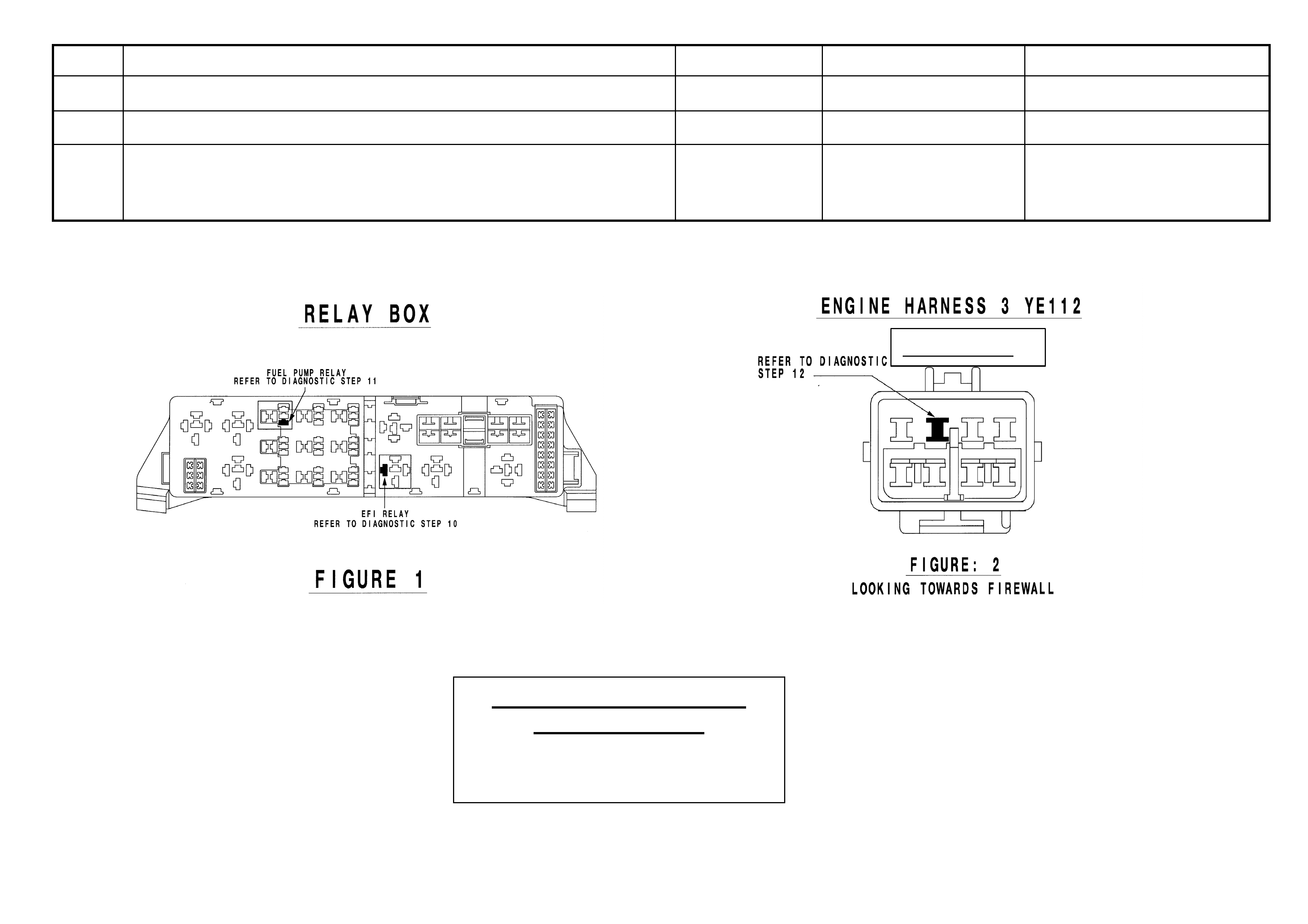
5 • Remove the EFI relay and back probe terminal 85 (as per figure 1 for VT.II / WH Vehicles or as per figure 3 for
VY / WK/ VZ Vehicles), with reference to Ground.
• With the Ignition switch to ON, measure DC voltage.
_____________ volts DC.
6 • Remove Fuel Pump relay and back probe terminal 1 (as per figure 1 for VT.II / WH Vehicles) or terminal.2 (as
per figure 3 for VY / WK Vehicles) , to measure continuity with ref. to Ground .
• Turn the ignition to ON, measure resistance.
_____________ Ohms.
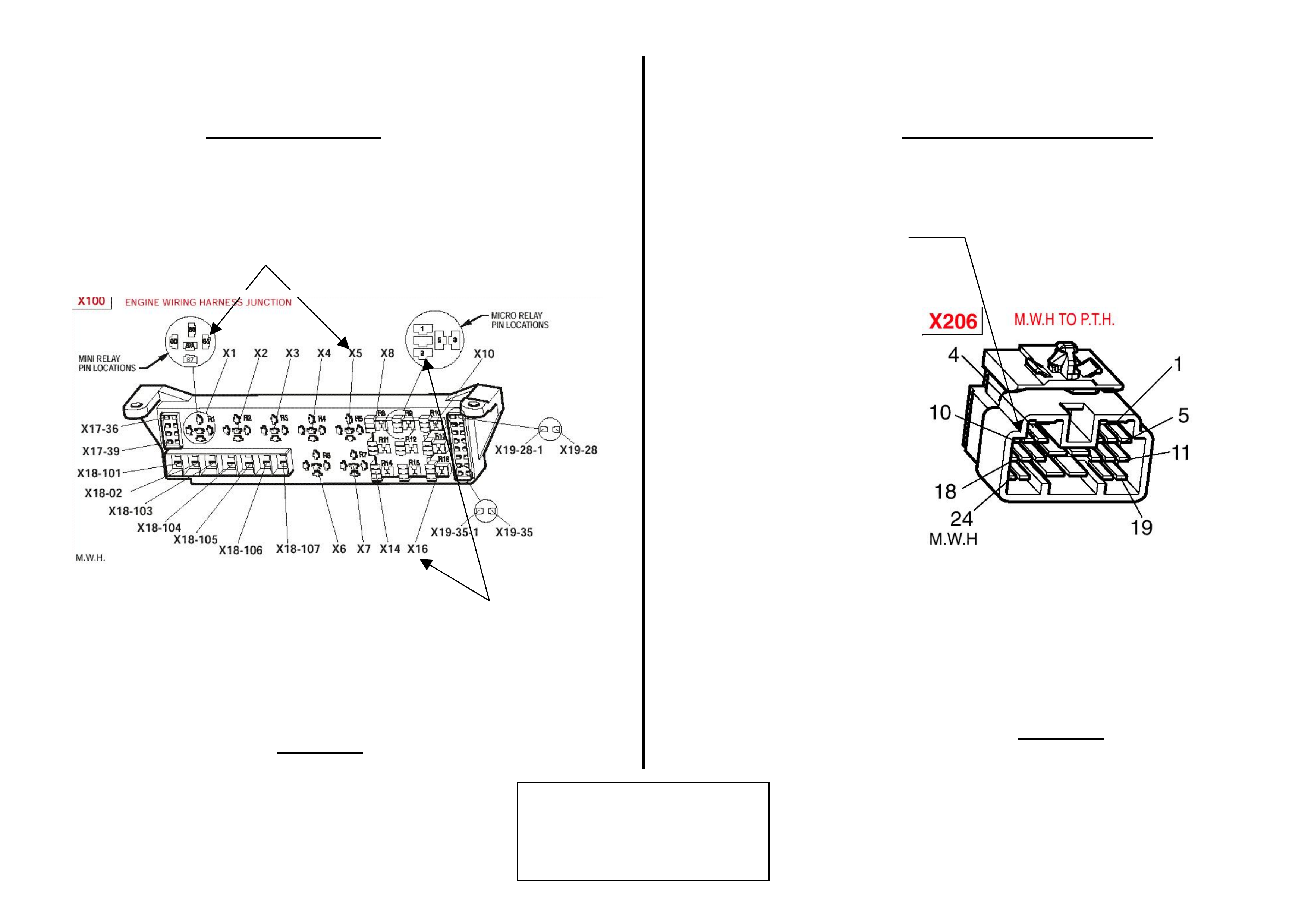
7 • For VY / WK Vehicles Disconnect Engine Connector (X206 located above passe nge r k i ck pa nel ) and back pr obe
pin 9 (as per figure 4) with reference to ground.
• For VT.II / WH Vehicles Di s c on nect En gi n e Connector (YE112) and back probe pin (as pe r fi g ure 2 ), wit h
reference to Ground.
• For VZ vehicles Disconnect ECM connector A43 X1 and back probe pin 19 (as per figure 5) with reference to
ground.
• Turn the ignition to ON, measure DC voltage.
_____________ volts DC
8 • Is communications with Tech 2 active?
9 • With TDL flashing, operate “Unlock” button on the Remote Control.
• Does the TDL stop flashing?
Dealer Code: ISOVIN: Vehicle Build Date:
Km’s: ESS Pin No: BCM Part No: BCM Barcode No: .
This check sheet must signed by the Service Manager. ____________________________ Date: ____________
Fax the completed copy to Australian Arrow Customer Service. Facsimile: (03) 9775 0954.

HSV – EMBEDDED SECURITY SYSTEM (ESS) DIAGNOSTIC PROCEDURE (VT.II / WH / VY / WK / VZ).
STEP ACTION VALUE YES NO
1 • Turn ignition to ON position.
• Is one (1) beep audible?
• Go to Step 2 • Go to Step 3.
2 • Turn Ignition switch to the Start position.
• Does the vehicle start?
• System O.K, return
vehicle to customer.
• Go to Step 11.
3 • Are five (5) beeps audible? • Go to Step 13. • Go to Step 8.
4 • Turn Ignition switch to the Start position.
• Does the vehicle start?
• Go to Step 5. • Go to Step 6.
5 • Fill in the ESS check sheet and Contact Australian Arrow
Customer Service.
6 • Has there been a BCM replacement? • Go to Step 5. • Go to Step 14.
7 • Perform Serial Data Communications diagnostic as per Holden
Service Manual, then go to Step 5.
8 • Zero beeps were audible? • Go to Step 9. • Record number of beeps,
then go to Step 5.
9 • Turn Ignition switch to the Start position.
• Does the vehicle start?
• Go to Step 5. • Go to Step 10.
10 • Remove the EFI relay and back probe terminal 85 (as per figure.1
for VT.II / WH vehicle), or (as per figure.3 for VY/WK/VZ
vehicle), with reference to Ground.
• With the Ignition switch to ON, Is the value as specified?
• 12 volts DC. • Go to Step 5. • Refer to Service Manual
and check Ignition
system.
11 • Remove Fuel Pump relay and back probe terminal.1 (as per figure.1
for VT.II / WH vehicle), or (as per figure.3 terminal.2 for
VY/WK/VZ vehicle), to check continuity with reference to Ground.
• Turn the ignition to ON. Is the value as specified?
• Less than one
(1) Ohm.
• Go to Step 12. • Go to Step 5.
12 • For VT.II / WH vehicle, Disconnect Engine Connector (YE112)
and back probe pin (as per figure 2), with reference to Ground.
• For VY/WK vehicle, Disconnect Engine Connector (X206 located
above passenger kick panel), and back probe pin.9 (as per figure.4),
with reference to ground.
• For VZ vehicles Disconnect ECM connector A43 X1 and back
probe terminal 19 (as per figure 5) with reference to ground.
• Turn the ignition to ON. Is the value as specified?
• 12 volts DC • Go to Step 5. • Go to Step 5.
STEP ACTION VALUE YES NO
13 • Is the Theft Deterrent Led flashing? • Go to Step 4. • Go to Step 5.
14 • Is communications with Tech 2 active? • Go to Step 15. • Go to Step 7.
15 • With TDL flashing, operate “Unlock” button on the Remote Key.
• Does the TDL stop flashing?
• Go to Step 5. • Refer to Theft Deterrent
System diagnostics in
Holden Service Manual.
(Grey Connector)
Australian Arrow Pty. Ltd.
Customer Service.
Telephone: (03) 9785 0792
Facsimile: (03) 9775 0954
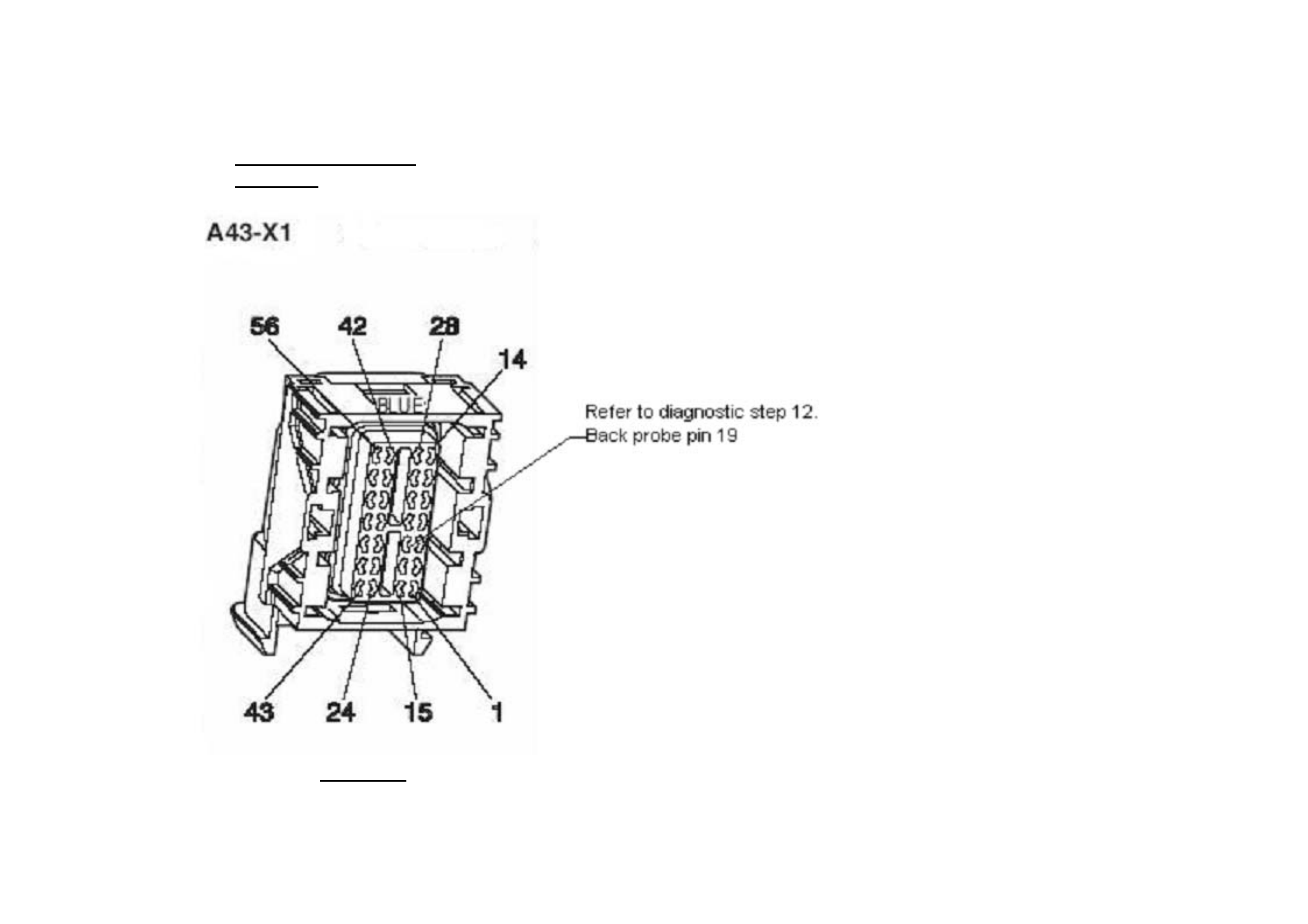
Engine control module
connector.
FIGURE 5
Fuel pump relay (X16)
Refer to diagnostic STEP 11
Back probe terminal 2
EFI relay (X5)
Refer to diagnostic Step 10
Back probe terminal 85
Refer to diagnostic step 12 (Pin 9)
FIGURE 3
Engine harness connector X206 Engine bay Relay Box
FIGURE 4
Australian Arrow Pty Ltd.
Customer Service
Telephone: (03) 9785 0792
Facsimile:(03)9775 0954

Page J-19
6 Electrochromic Mirrors
6.1 General
Electrochromic mirrors are standard fitment to all VYII Senator vehicles. The mirror features an electronically controlled mirror
cell which changes colour in r esponse to an applied electrical voltage. This allows automatic darkening of the mirror during
night driving when the hea dlamps of a following vehicle shine on an integrated light sensor. This function only operat es
when the integral sensor detects low ambient light. (i.e. at night time). The mirror operates automatically however, an
AUTO/MANUAL switch provides the driver with the option for the mirror to be darkened durin g low ambient light conditions
regardless of presence or absence of following headlamps. When reverse gear is selected, the mirror automaticall y lightens.

Page J-20
7 HSV Rear Entertainment System
7.1 General
HSV VY II vehicles can be optioned with a Rear entertainment system. The system consists of the following;
Over head mount screen
A 7” TFT flip down screen can be fitted in 2 configurations;
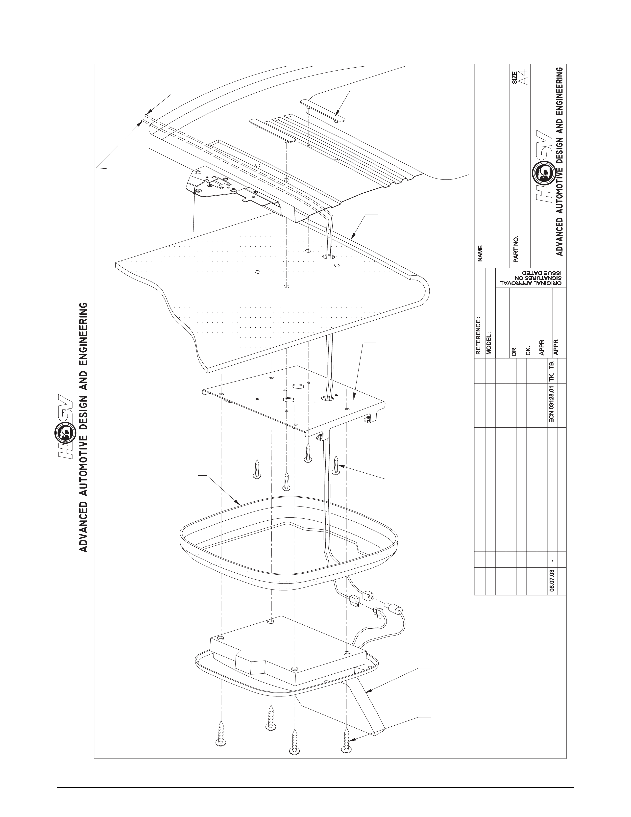
(1) Fitted to a roof bow of the vehicle for vehicles that do not have a sunroof fitted as per the instruction drawing
labelled “OVERHEAD SCREEN ASM (NON SUNROOF CAR)”
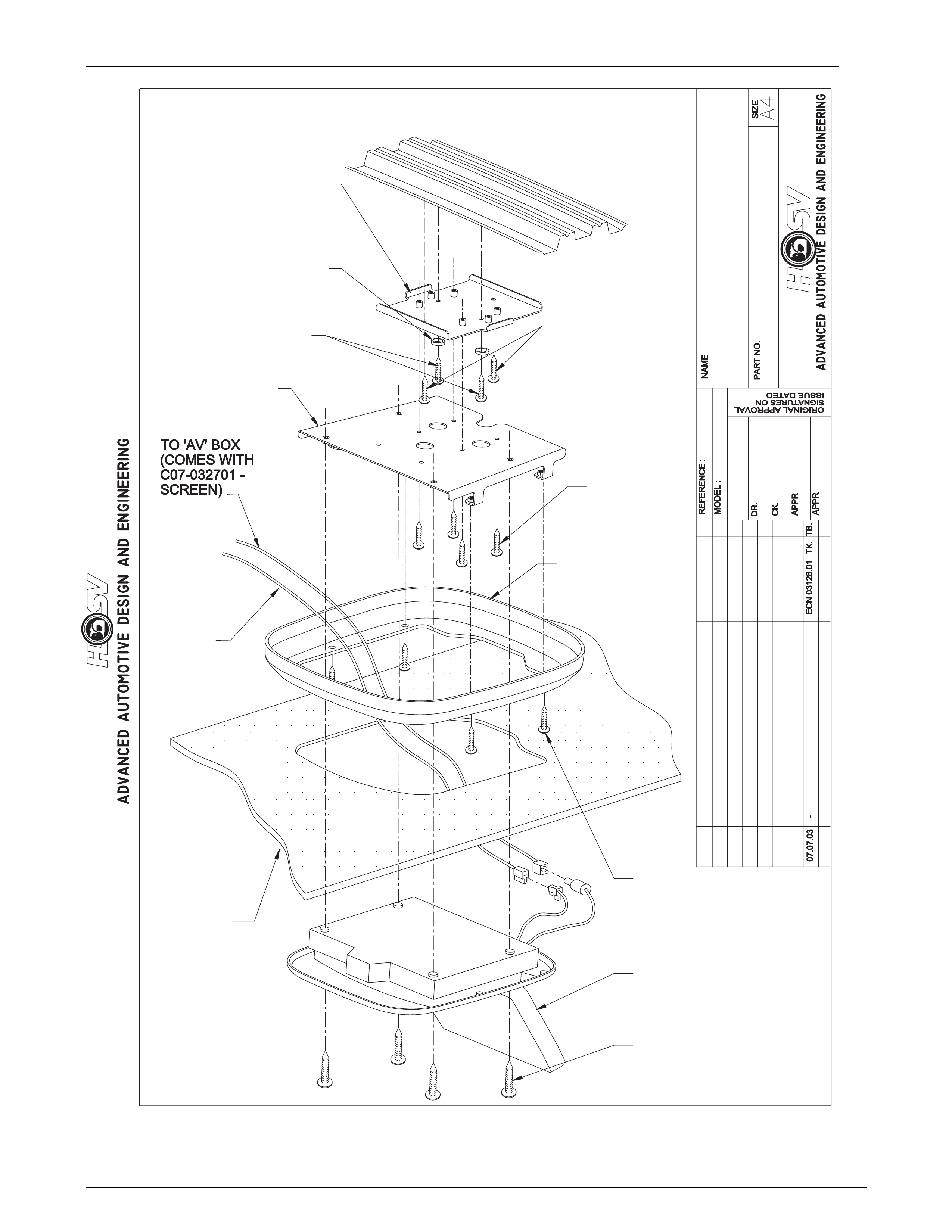
(2) The drip tray of the sunroof cassette of vehicles that have a sunroof fitted as per the instruction drawing labelled
“OVERHEAD SCREEN ASM (SUNROOF CAR)”.
The screen assembly has an inbuilt dome lamp that should operate in conjunction with the interior roof lamps of the car.
Switching Box
The screen has an auxiliary switching box that is fitted to the undersid e of the parcel tray in the boot. The switching box
allows a number of auxil iary inputs to be connected to the system and switched from the cabin via the remote control. In
standard form the DVD and games port (that is fitted behind centre fold down seat above the access hole to the boot as per
as per the instruction drawing lab elled “GAMES PORT”) are the only inputs connected to the s witching box.
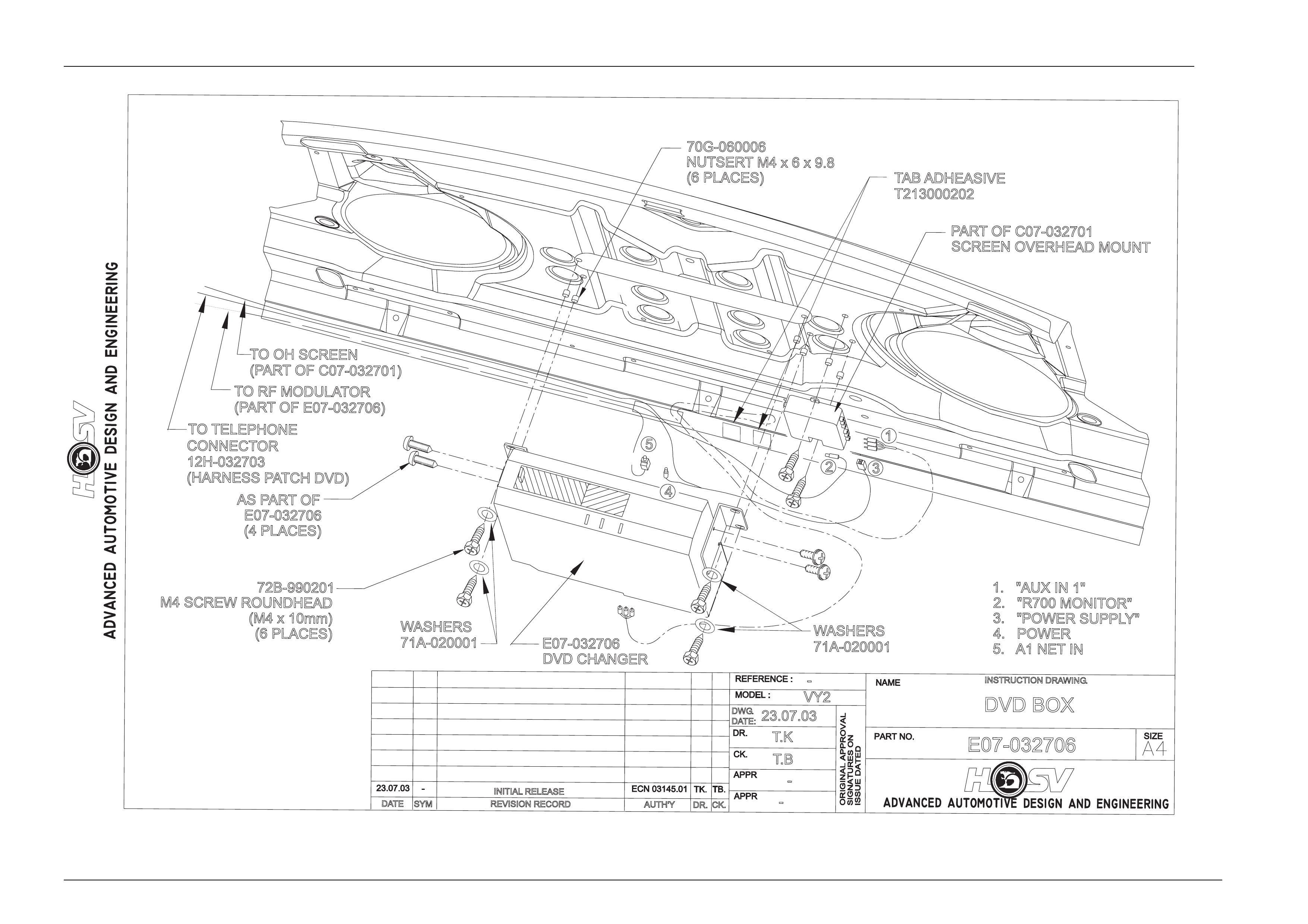
6 Disc DVD Changer
A DVD changer is fitted to the underside of the parcel tray in the boot as per the instruction drawing “DVD BOX”. The DVD
changer can be controlled from the
(1) The driver controls / display
(2) The remote control (with the switch on it’s right side set to “DVD”). The remote must be pointed at the dark window
near the inbuilt dome lamp on the screen.
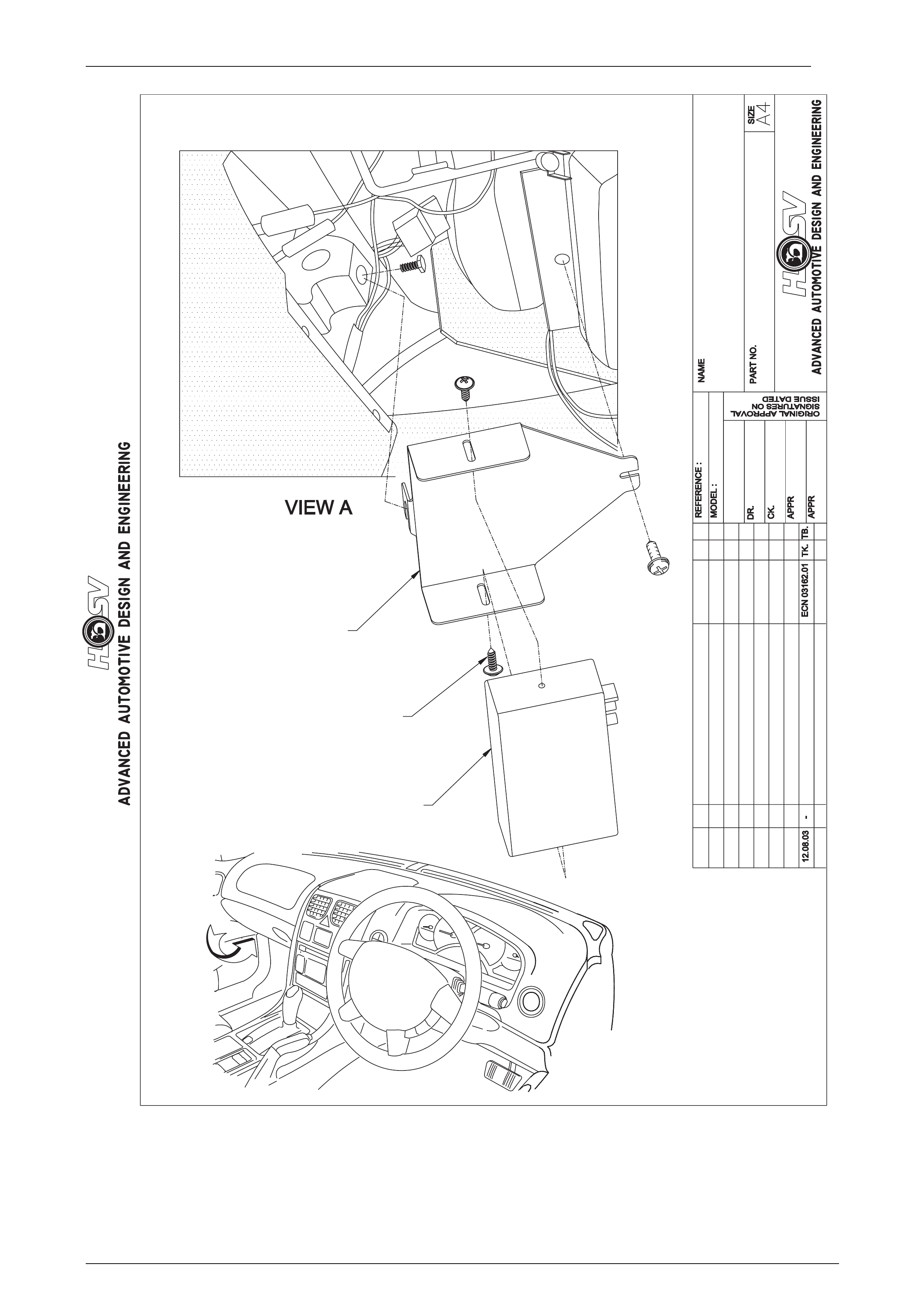
Radio Frequency Modulator
An RF modulator is fitted behind the glove box as sho wn in the instruction drawing labelled “RF MODULATOR ASSEMBLY”.
The RF modulator converts the audio signal from the DVD player into a radio freque ncy that the radio can receive via i ts
tuner. The factory default frequency is 88.7MHz. This frequency can be modified via the Driver controls/displa y (refer owners
manual).
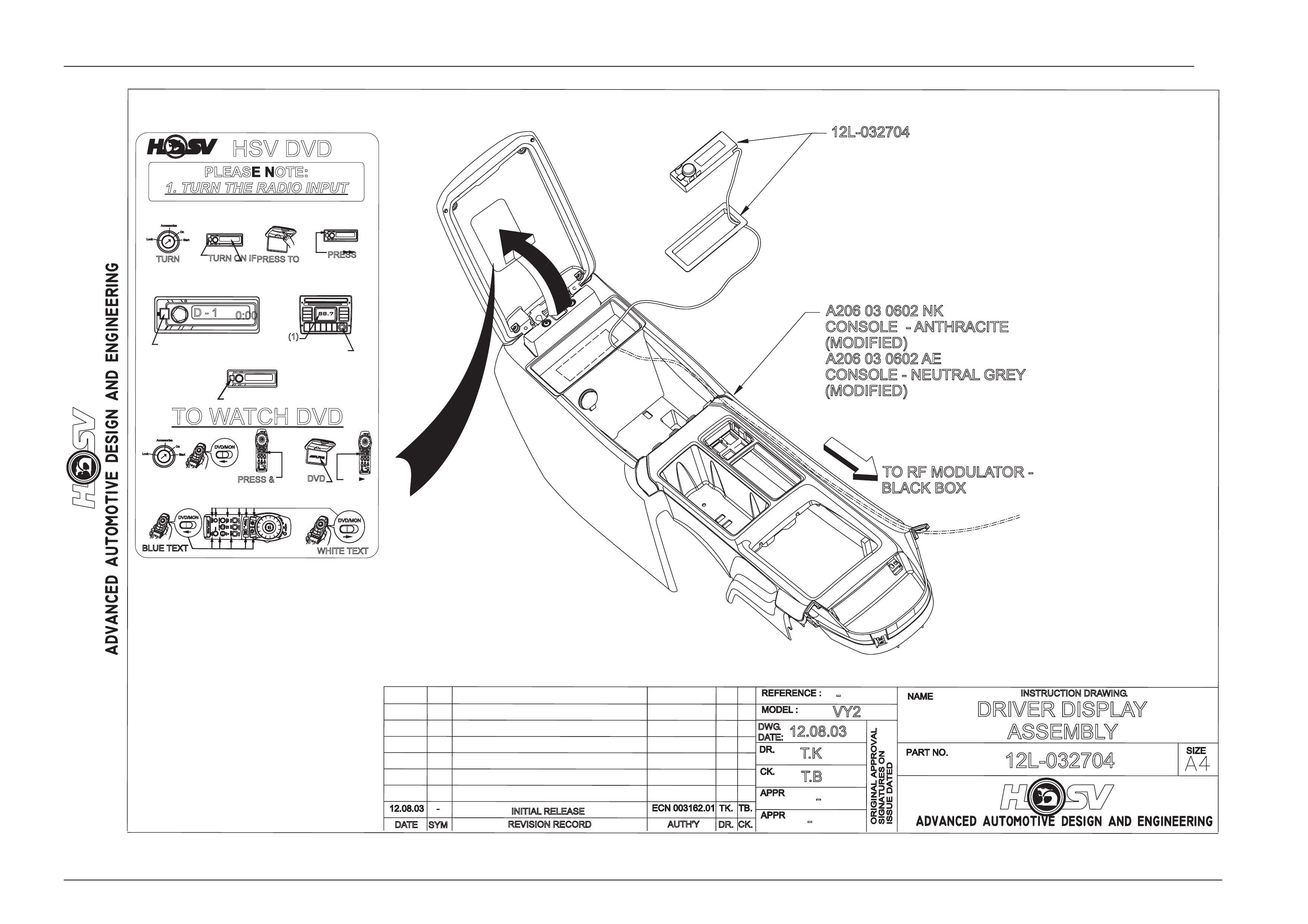
Driver Controls/Display
A driver display unit is fitted at the rear of the centre console compartment as sho wn in the instructio n drawing “DRIVER
DISPLAY ASSEMBLY”.
The driver control/display e nables the driver to control functions of the DVD player and the RF modulator as per the owners
manual.
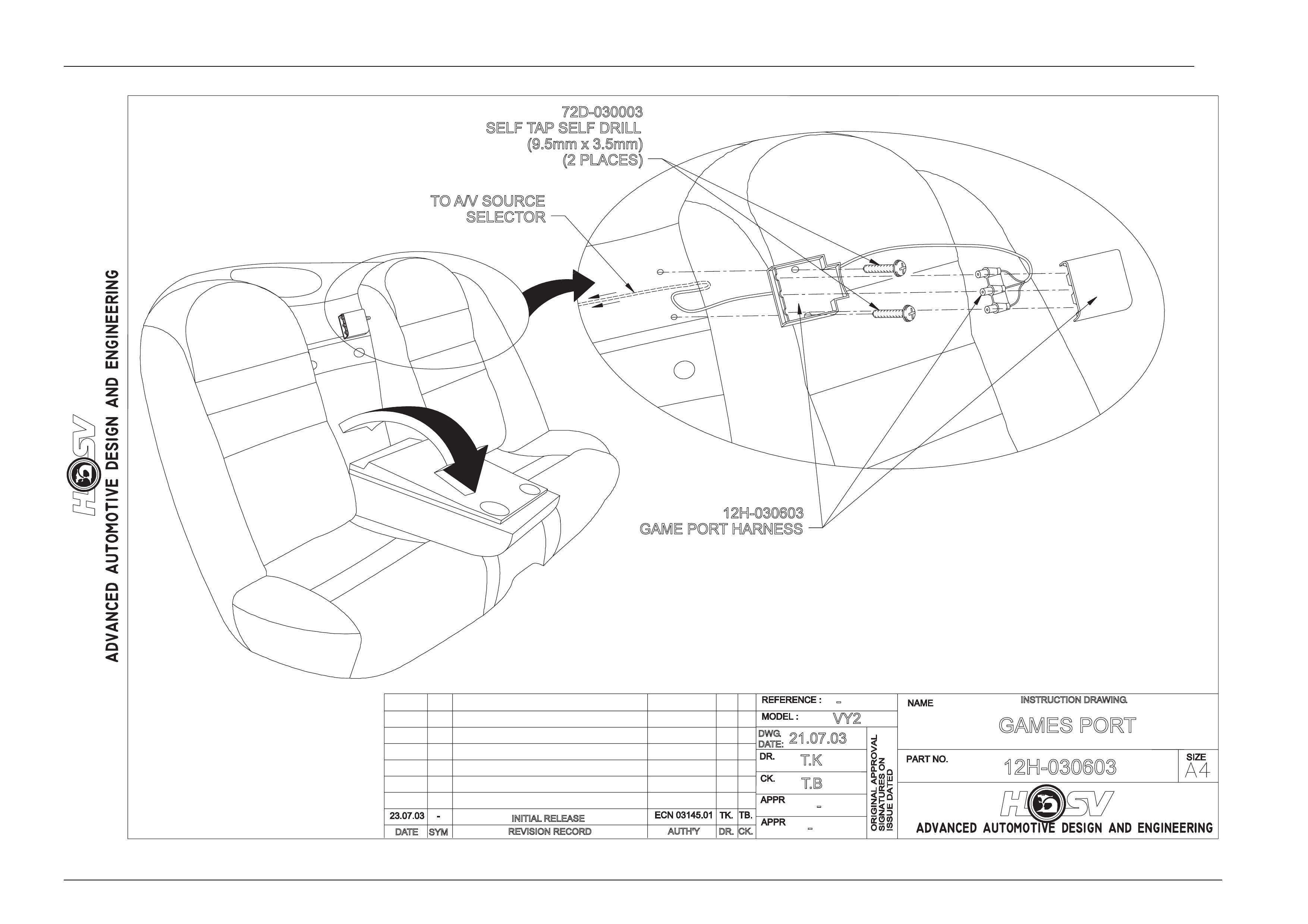
Games Port
A games port is fitted behind centre fold down seat above the access hole to the boot as per as per the instruction dra wing
labelled “GAMES PORT”.
The games port allows the user to connect an auxiliary inpu t (such as video camera or gam es console) into the rear
entertainment system. The games port can be accessed by selecting “AUX 1” using the remote control with the s witch on the
right side in “MONITOR” position.
Page J-21
Page J-22
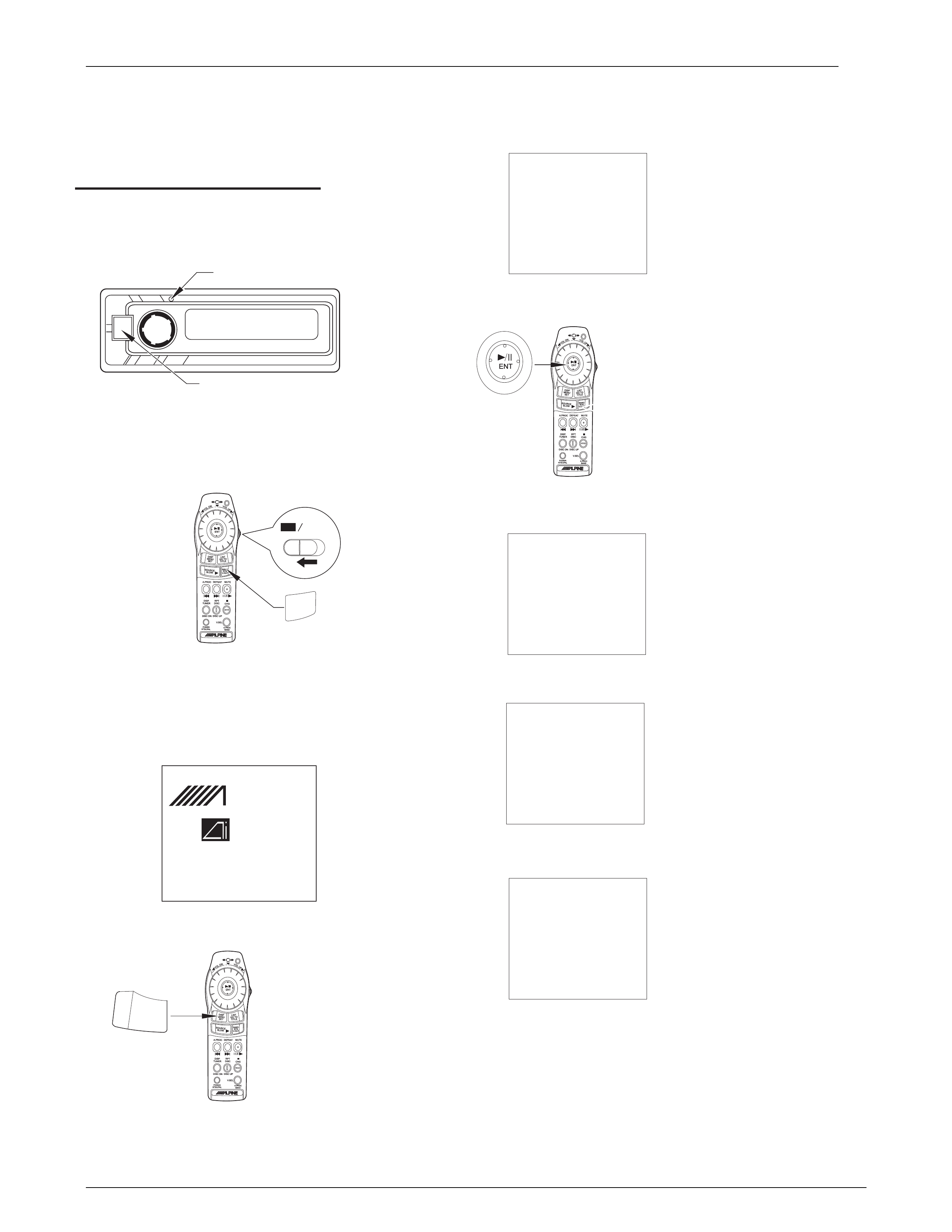
System Reset
System reset instructions
after vehicle power loss
Radio Input Control
1
5
6
7
8
9
2
3
4
The following steps are to be followed after your
vehicles battery has been disconnected or
flattened and you wish to restart the system.
Turn the vehicle’s ignition on. Press the
RESET button with a pen, then press the
POWER button on the Radio Input Control.
Open the monitor by pressing the PUSH button.
Slide the Remote switch to DVD.
Press and hold the V.OUT button for eight
seconds whilst aiming at the remote window
located near the PUSH button on the monitor.
The DVD start screen will show (as above)
The Setup screen will show (as above)
Use the Joystick to move to CUSTOM SETUP
and select by pressing the joystick button.
The CUSTOM SETUP screen will show (as above)
Using the Joystick change the AI-NET and H.U.
CONTROL settings to match the screen above.
Press and hold the SET button for three
seconds to save the settings and exit the screen.
The start sceen will show again.
Whilst aiming the remote at the rear of
screen case, press and hold the set button
for two seconds.
SETUP
LANGUAGES
TV SCREEN 16:9
COUNTRY CODE 8583
RATING LEVEL OFF
DOWN SAMPLING ON
DIGITAL OUT AUTO
LED INDICATOR ON
CUSTOM SETUP
CUSTOM SETUP
CLOSED CAPTION OFF
AI-NET SETUP CD
H.U. CONTROL ON
SETUP
LANGUAGES
TV SCREEN 16:9
COUNTRY CODE 8583
RATING LEVEL OFF
DOWN SAMPLING ON
DIGITAL OUT AUTO
LED INDICATOR ON
CUSTOM SETUP
CUSTOM SETUP
CLOSED CAPTION OFF
AI-NET SETUP DVD
H.U. CONTROL OFF
RESET
POWER
DVD Monitor
V.OUT
LPINE
- NET
DVD/VIDEO CD/CD
CHANGER
SET
Page J-23
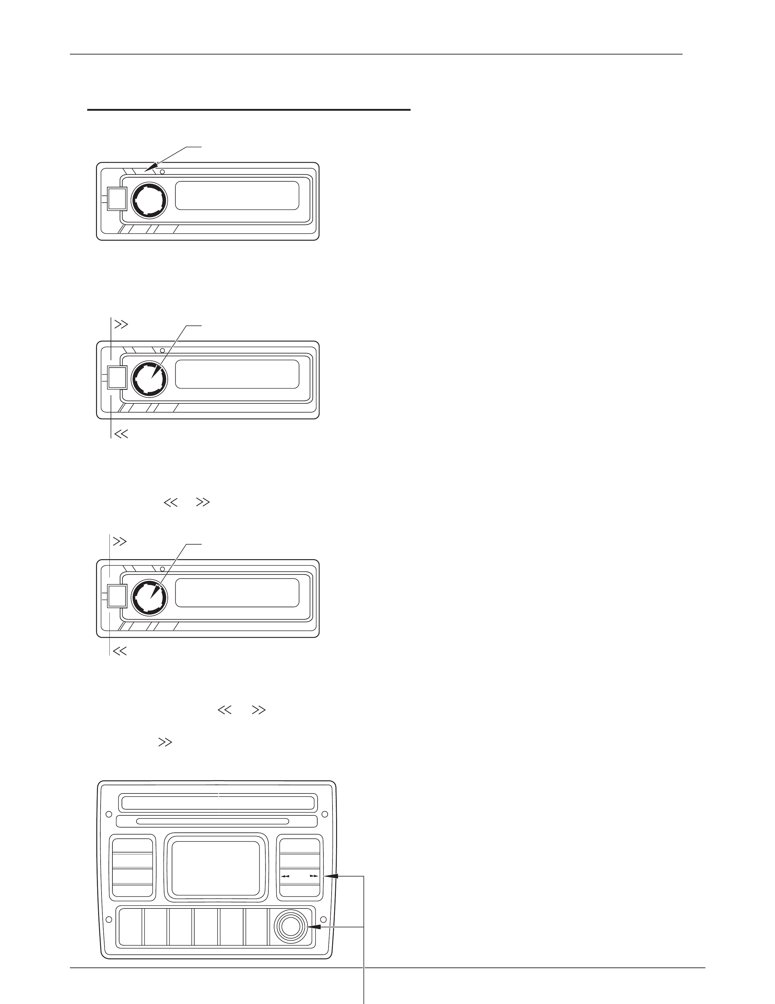
System Reset
Continued
10
11
12
13
Press and hold the SETUP button for three
seconds
DISP/SETUP
Turn the Rotary Encoder until the Frequency is
shown. The frequency should show 88.7 Mhz.
If not press or until the correct frequency is shown.
Tune the vehicles radio to 88.7 Mhz on the
FM b d d l l i th l
Turn the Rotary Encoder until “AUX” is shown
on the screen. Press or to show “AUX
OFF”. Press SETUP to exit.
Now press to start a DVD.
88.7
ROTORY ENCODER
88.7 MHz
ROTORY ENCODER
AUX OFF
TUNE
Page J-24
REVISION RECORD
SYM
DATE
INSTRUCTION DRAWING.
-
AUTH'Y CK.
DR. -
VY2
T.K
T.B.
07.07.03
DWG.
DATE:
C07-032701
-
OVERHEAD SCREEN ASM.
(NON SUNROOF CAR)
INITIAL RELEASE
72B-030003
M4 SCREW
M4 SCREW
ROUND HEADROUND HEAD
(4 PLACES)(4 PLACES)
C07-032703
TRIM DVD SCREEN
TRIM DVD SCREEN
(RAW)
C07-032701
SCREEN DVD.
SCREEN DVD.
OVERHEAD MOUNTOVERHEAD MOUNT
72B-990201
M4 x 10mm
M4 x 10mm
ROUND HEADROUND HEAD
(4 PLACES)(4 PLACES)
C07-032702
BRACKET - DVD
BRACKET - DVD
SCREEN TO ROOFSCREEN TO ROOF
70G-060005
STANDOFF PLATE
STANDOFF PLATE
ROOF BOWROOF BOW
(NON SUNROOF)(NON SUNROOF)
72D-030003
SCREW SELF TAP
SCREW SELF TAP
SELF DRILLSELF DRILL
(2 PLACES)(2 PLACES)
HEADLINER
BOARD - VEHICLE
BOARD - VEHICLE
(IN VEHICLE)(IN VEHICLE)
72B-990201
M4 x 10mm
M4 x 10mm
ROUND HEADROUND HEAD
(4 PLACES)(4 PLACES)
71E-020003
SPACER
OD 16mm x ID 6mm
OD 16mm x ID 6mm
x 3mm THICKx 3mm THICK
(2 PLACES)(2 PLACES)
72D-030004
SCREW SELF TAPSCREW SELF TAP
(2 PLACES)(2 PLACES)
TO 'GRABTO 'GRAB
HANDLE LAMP'HANDLE LAMP'
12H-030604
HARNESS - PATCH
HARNESS - PATCH
LIGHTING - V.I.C.E.LIGHTING - V.I.C.E.
Page J-25
REVISION RECORD
SYM
DATE
INSTRUCTION DRAWING.
-
AUTH'Y CK.
DR.
-
VY2
T.K
T.B.
08.07.03
DWG.
DATE:
C07-032702
-OVERHEAD SCREEN ASM.
(SUNROOF CAR)
INITIAL RELEASE
PART OF C07-032701PART OF C07-032701
SCREEN DVD.SCREEN DVD.
OVERHEAD MOUNTOVERHEAD MOUNT
(4 PLACES)(4 PLACES)
C07-032703NK
TRIM DVD SCREEN
TRIM DVD SCREEN
(ANTHRACITE)
C07-032703AE
TRIM DVD SCREEN
TRIM DVD SCREEN
(NEUTRAL GREY)
C07-032701
SCREEN DVD.
SCREEN DVD.
OVERHEAD MOUNTOVERHEAD MOUNT
72B-990201
M4 x 10mm
M4 x 10mm
PAN HEADPAN HEAD
(4 PLACES)(4 PLACES)
C07-032702
BRACKET - DVD
BRACKET - DVD
SCREEN TO ROOFSCREEN TO ROOF
HEADLINER
BOARD - VEHICLE
BOARD - VEHICLE
70G-060004
BRACKET
(2 PLACES)
(2 PLACES)
SUNROOF
TO 'AV' BOXTO 'AV' BOX
(COMES WITH C07-032701(COMES WITH C07-032701
- SCREEN)- SCREEN)
TO 'GRAB 'TO 'GRAB '
HANDLE LIGHTHANDLE LIGHT
12H-030604
HARNESS
PATCH LIGHTING
PATCH LIGHTING
V.I.C.E.
Page J-26
SY
DATE
TOOHSCREEN
(PARTOFC
07-032701)
TORFM
ODULATOR
(PARTOFE
07-032706)
TOTELEPHONE
CONNECTOR
12H-032703
(HARNESSPATCHDVD)
WA
71A
INSTRUCTIONDRAWING.
E07-032706
DVDBOX
1."A
UXIN 1"
2."R
700MONITOR"
3."P
OWERSUPPLY"
4.P
OWER
5.A1NETIN
1
3
ERS
0001
PARTOFC
07-032701
SCREENOVERHEADMOUNT
TABADHEASIVE
T213000202
72B-990201
M4SCREWROUNDHEAD
(M4x1
0mm)
(6 PLACES)
ASPARTOF
E07-032706
(4 PLACES)
-
AUTH'YCK.
DR.
-
VY2
T.K
T.B
23.07.03
DWG.
DATE:
-
2
5
4
WASH
71A-02
70G-060006
NUTSERTM4x6x9
.8
(6 PLACES)
ER
REVISIONRECORD
M
INITIALRELEASE
SHERS
-020001E07-032706
DVDCHANG
Page J-27
SYM
INSTRUCTION DRAWING.
12L-032704
DRIVER DISPLAY
ASSEMBLY
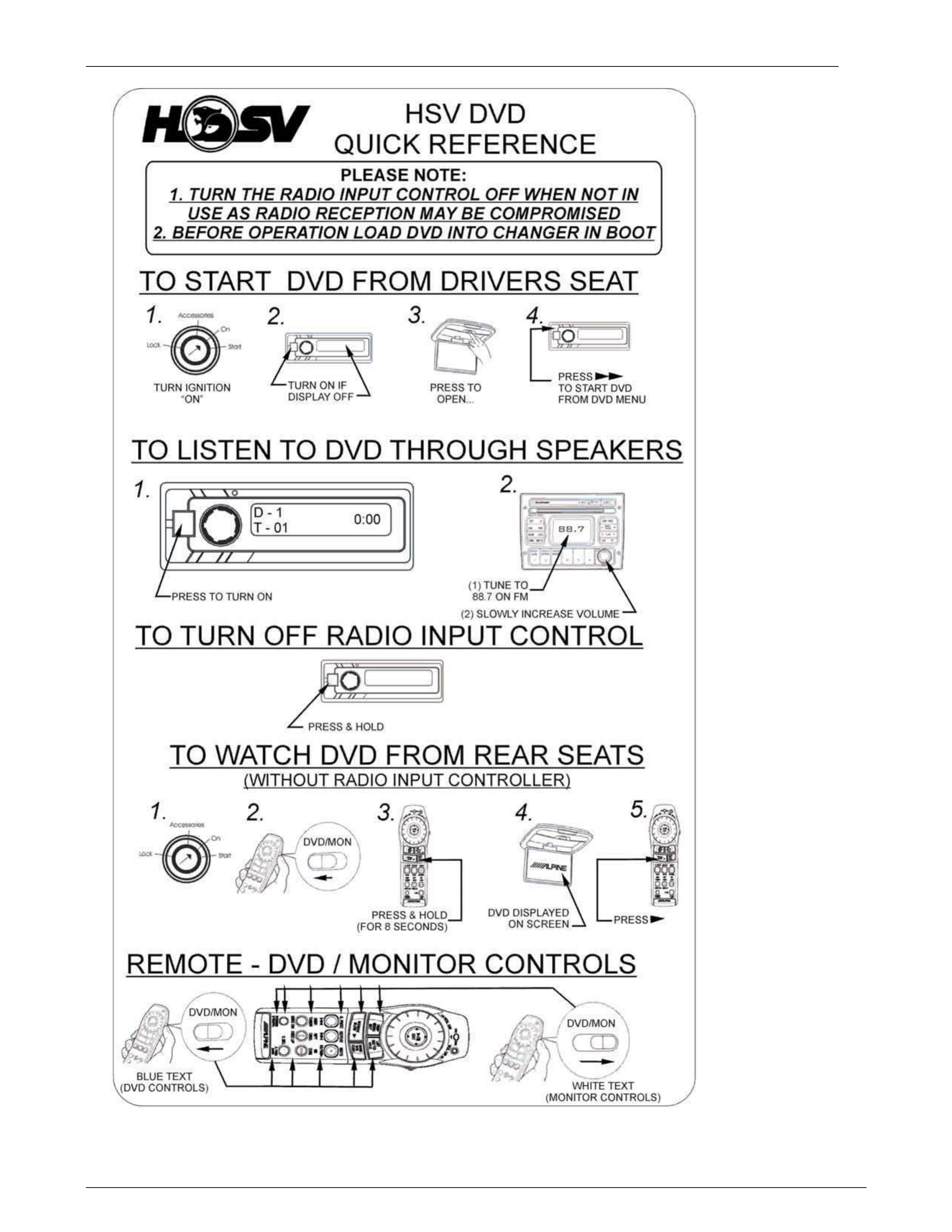
TOW
ATCH DVD
TURN ON IFPRESS TO
(1)
PRESS & DVD
HSV DVD
TURN
BLUE TEXT WHITE TEXT
PLEASE NOTE:
1. TURN THE RADIO INPUT
PRESS
D-1 0:00
88.7
DVD/MON
V
O
L
O
N
V
O
L
U
P
ENT
DISP
MENU
SET
LIST
GOTO
TITLE
SOURCE
SLOW
BAND
RTN
V
.OUT
A.PROCDEFEATMUTE
DISP.
TUNER
RPT
DISCCHG
DISCDNDISCUP
V
.SEL
A.PROC
BAND
POWER
NTSC/PAL
DVD/MON
DVD/MON
V
O
L
O
N
V
O
L
U
P
ENT
DISP
MENU
SET
LIST
GOTO
TITLE
SOURCE
SLOW
BAND
RTN
V.OUT
A.PROCDEFEATMUTE
DISP.
TUNER
RPT
DISCCHG
DISCDNDISCUP
V.SEL
A.PROC
BAND
POWER
NTSC/PAL
V
O
L
O
N
V
O
L
U
P
ENT
DISP
MENU
SET
LIST
GOTO
TITLE
BAND
RTN
V
.OUT
A.PROCDEFEATMUTE
DISP
.
TUNER
RPT
DISCCHG
DISCDNDISCUP
V
.SEL
A.PROC
BAND
POWER
NTSC/P
AL
DATE
O RF MODULATOR -
BLACK BOX
REVISION RECORD
INITIAL RELEASE
AUTH'YCK.
DR.
DA
A206 03 0602 NK
ANTHRACITE
AE
CONSOLE - NEUTRAL GREY
-
-
VY2
T.K
T.B
12.08.03
DWG.
TE:
-
T
12L-032704
CONSOLE -
(MODIFIED)
A206 03 0602
(MODIFIED)
Page J-28
INITIAL RELEASE
RFMODULATOR
ASSEMBLY
-
E07-032707
DATE:
DWG.
12.08.03
T.B.
T.K
VY2
-
DR.CK.AUTH'Y
-
INSTRUCTIONDRAWING.
DATESYM REVISIONRECORD
A
12L-03270412L-032704
72B-99020172B-990201
(2 PLACES)(2 PLACES)
E07-032707E07-032707
Page J-29
REVISION RECORD
SYM
DATE
INSTRUCTION DRAWING.
-
AUTH'Y CK.
DR.
-
VY2
T.K
T.B
21.07.03
DWG.
DATE:
12H-030603
-
GAMES PORT
INITIAL RELEASE
TO A/V SOURCE
SELECTOR
72D-030003
SELF TAP SELF DRILL
(9.5mm x 3.5mm)
(2 PLACES)
12H-030603
GAME PORT HARNESS
Page J-30
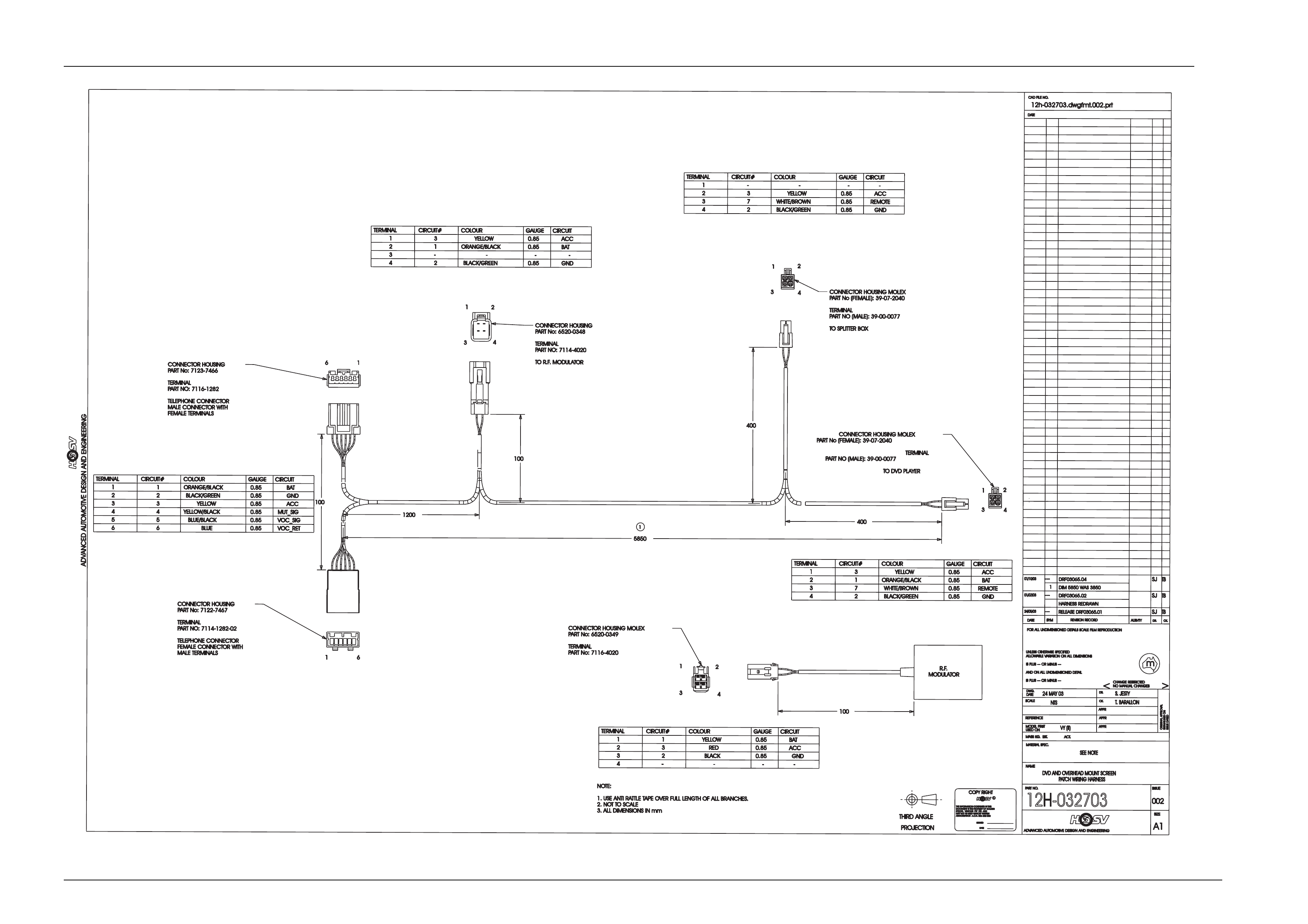
0.85
GND
4
2
30.85
ACC
-
1
CIRCUIT#
-
CIRCUIT
2BLACK/GREEN
7
GND
0.85
WHITE/BROWN
3
YELLOW
3
TERMINAL
ORANGE/BLACK
GAUGE
COLOUR
0.85
TERMINAL
BLACK/GREEN
2
-
-
-
2
1
COLOUR
REMOTE
GAUGE
RELEASEDRF03065.01
UNLESSO
THERWISES
PECIFIED
m
AUTH'TY
A1
APPR
>
AUTHORISATIONA.C.N.0
06802053
DWG.
THIRDA
NGLE
SYM
S. JESTY
NOMANUALCHANGES
SPECIALVEHICLESPTYLTDAND
12h-032703.dwgfmt.002.prt
REFERENCE
SIGNATURESON
12H-032703
ANDO
NA
LLUNDIMENSIONEDD
ETAIL
MATERIALSPEC.
CK.
24 MAY03
SEE NOTE
THEI
NFORMATIONC
ONTAINEDINTHIS
FORA
LLUNDIMENSIONEDD
ETAILSS
CALEF
ILMR
EPRODUCTION
DR.
DATE
ADVANCED AUTOMOTIVE DESIGNAND ENGINEERING
NAME
C
ADVANCED AUTOMOTIVE DESIGN AND ENGINEERING
APPR
SIZE
DATE
SIGNED
CK.
24/05/03
PARTN
O.
DVD AND OVERHEAD MOUNT SCREEN
PATCH WIRING HARNESS
APPR
NTS
COPYRIGHT
USEDO
N
<
MAYN
OTB
EUSEDWITHOUTW
RITTEN
PROJECTION
SCALE
ISSUED
ATED
T. BARALLON
DATE
ISSUE
ISP
LUS-
--O
RM
INUS-
--
MASSK
G.E
ST.ACT.
CHANGER
ESTRICTED
DOCUMENTISTHEPROPERTYO
FH
OLDEN
DR.
ALLOWABLEV
ARIATIONO
NA
LLDIMENSIONS
MODELFIRST
ORIGINALA
PPROVAL
002
ISP
LUS-
--O
RM
INUS-
--
REVISIONR
ECORD
CAD FILENO.
DATE
--- SJ
0.85
5
0.85BAT
ACC
1
CIRCUIT#
0.85
CIRCUIT
YELLOW
1
TERMINAL GAUGE
2RED
3
COLOUR
ACC
4
0.85
30.85
4
6
2
-
BLACK
0.85
6
CIRCUIT
-
-
VOC_SIG
-
BLUE/BLACK
GND
YELLOW/BLACK
YELLOW
MUT_SIG
3
BLUE
0.85
3
VOC_RET
4
5
2BLACK/GREEN
2
1ORANGE/BLACK
0.85
1
GND
BAT
0.85
COLOURGAUGE
TERMINAL CIRCUIT#
YELLOW0.85
-
4
-
3-
ACC
BAT
CIRCUIT
0.85
CIRCUIT#
1
0.85ACC
BAT
1
CIRCUIT#
0.85
CIRCUIT
YELLOW
3
TERMINAL GAUGE
2ORANGE/BLACK
1
COLOUR
4
30.85
7
GND
WHITE/BROWN
0.85
BLACK/GREEN
2
REMOTE
CONNECTORHOUSING
PART No:7
123-7466
TERMINAL
PART NO:7
116-1282
TELEPHONE CONNECTOR
MALEC
ONNECTORWITH
FEMALE TERMINALS
CONNECTORHOUSING
PART No:7
122-7467
TERMINAL
PART NO:7
114-1282-02
TELEPHONE CONNECTOR
FEMALEC
ONNECTORWITH
MALE TERMINALS
1
1
6
6
12
4
3
CONNECTORHOUSING
PART No:6
520-0348
TERMINAL
PART NO:7
114-4020
TOR.F
.MO
DULATOR
12
4
3
2
4
3
1
CONNECTORHOUSING MOLEX
PART No (FEMALE): 39-07-2040
TERMINAL
PART NO (MALE): 39-00-0077
TOSPLITTER BOX
CONNECTORHOUSING MOLEX
PART No (FEMALE): 39-07-2040
TERMINAL
PART NO (MALE): 39-00-0077
TODVD PLAYER
34
2
1R.F
.
MODULATOR
CONNECTORHOUSING MOLEX
PART No:6
520-0349
TERMINAL
PART No:7
116-4020
100
400
1200
5850
100
400
100
NOTE:
1.U
SE ANTI RATTLETAPE OVER FULLLENGTH OFAL
LBRANCHES.
2.NO
TT
OSCALE
3.AL
LDIMENSIONS IN mm
TB
VY (II)
HARNESS REDRAWN
01/07/03
---
DRF03065.02
SJ
TB
01/10/03
---
DIM 5850WAS3
850
DRF03065.04
SJ
TB
1
1

Page J-31
7.2 HSV DVD Entertainment System
System, Warranty And Procedures Information
Introduction
This DVD Entertainment System utilises a state of the art 7” roof mounted, fold down screen connected to a 6-Disc DV D,
Video CD and Audio CD cha nger. It has been designed to be integrated into the vehicles interior, allo wing the rear seat
passengers to enjoy DVD or CD’s as well offering a Video Game input. An RF Modulator has been included to allow the
DVD changers’ audio to be accessible through the vehic le’s radio.
This system will be available as an Option fit at point of manufacture for any VY2 sedan.
Date of introduction will be August 2003.
This document is intended to be a guide on how Alpine will manage the systems introduction, delivery, warranty and
other relevant procedures.
System Components
Description HSV Part # Components
Radio Input Control 12L-032704 Module, controller, trim, cable
DVD 6-Disc Changer E07-032706 Changer, Ai-Net cable,
cartridge, cartridge label
Roof mounted Monitor C07-032701 Monitor, module, cable
HSV Cordless H/P 12L-032703 (1) set of H/Phones with HSV
logo, batteries
Integrated DVD remote 12L-032705 (1) remote with HSV logo
Trim - Raw C07-032703 Black ABS trim - uncovered
Trim - Anthracite C07-032703NK Anthracite covered trim
Trim - Neutral Grey C07-032703AE Neutral Grey covered trim
Games port 12H-030603 Games input port
Owner's Manual 00A-030609 Owner’s Manual A5 bound
Instruction sticker 00A-030608 Cons ole lid mounted sticker
Monitor mounting screws 72B-030003 (4) x M4 x 25mm black
Radio Input mount screws TBA (2) x M4 x 6mm
Purchase Of Components
The list above shows the part numbers for replacement components. The parts shown above can only be ordered by a
HSV dealer to replace a stolen or damaged compo nent. T hese replacement components carry a standard return to
Alpine, 12 month warrant y without labour recompense. This is different to the warranty for a first installed complete kit,
which is three years.
Page J-32
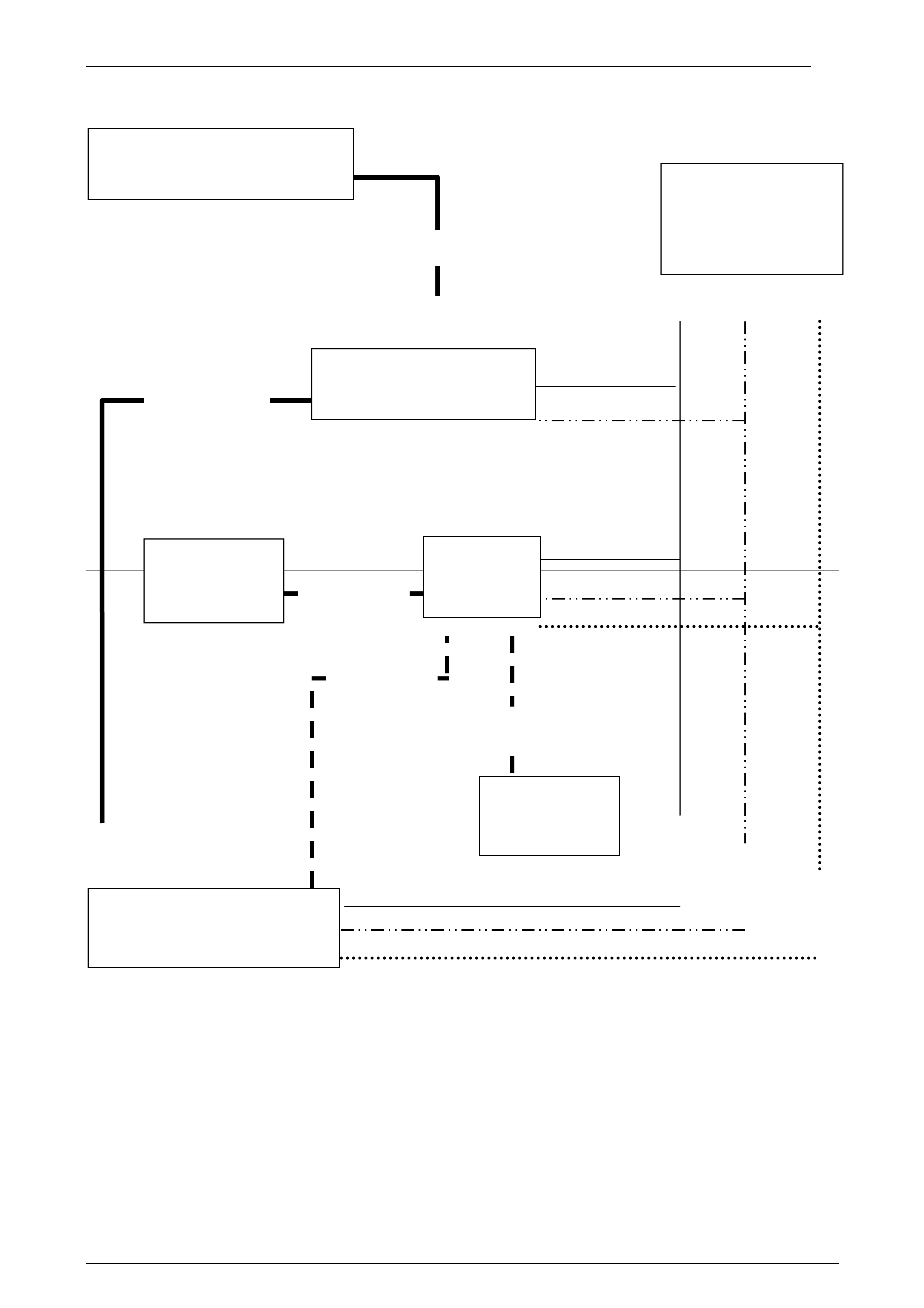
System Configuration
MONITOR
SCREEN
[roof]
MONITOR
MODULE
[in boot]
DVD CHANGER
[in boot]
RADIO INPUT CONTROLLER
(RF MODULATOR)
RADIO INPUT MODULE
(RF MODULATOR)
PHONE POWER
CONNECTOR
Gr Acc B+
Ai
-
Net cable
DIN Cable
DIN Cable
RCA cable
GAME INPUT
[behind fold
down seat]
RCA cable

Page J-33
Warranty Policy
The purpose of this document is to state the specifics of the warrant y policy and the respo nsibilities of each party namely
Holden Special Vehicles (HSV) and Alpine Electronics of Australia Pty Ltd (Alpine). T his applies to the warranty for the
products listed belo w and includes labour to remove the product for repair. T he product covered is: TMX-R700 Monitor,
DHA-S680E DVD Changer, CRA-1667RF RF modulator, Cordless Headphon es and fitment accessories. This warranty
does not cover anything not listed as an Al pine part. Therefore HSV sourced components are not covered.
Warranty period
This warranty is valid for 36 months from the date of deliver y of the vehicle or from the date of fitment of the s ystem in a
previously registered vehicle whichever is th e latest. This warranty only applies to units supplied to Holden Spec ial
Vehicles and subsequ ently sold to the Holden Special Vehicles dealer network. This warranty and policy document will
also only apply to units fitted by trained installers following an approved installation procedure. This warranty covers the
repair of Alpine components returned to Alpi ne for repair where a manufacturing or material defect has occurred.
Please also note this warrant y only applies to the vehicle of first fitment. Removal of the components from a vehicle for
fitment into another vehicle may void the warranty.
Warranty Charges
If the unit is within 36 months old from its fitment or the original new vehicle delivery date which ever is the latest and the
failure was as a result of a manufacturing or material defect only, there will be no charges made to HSV or the dealer for
its rectification.
Non-Warranty Charges
If the unit is over 36 months old from its fitment or original new vehicle delivery date which ever is the latest there will be
a charge made to the HSV dealer submitting the unit for repair based on the labour time taken and the parts requir ed to
effect the repair. The labour will be charged at $70 per hour including GST (subject to change) and parts will be charged
at the current retail cost. The freight to return the repaired unit will be charged at $27.00 incl GST. A quote will be
provided prior to repair, ho wever for a retail repair, if the total repair cost will be under $150 (incl GST) the unit will be
automatically repaired without consultation. The HSV dealer will then be require d to effect payment (Direct debit, CC or
CHQ) prior to the unit being returned.
Damaged Units
If any damage is noted this will be considered to be not warrantable and the necessary charges to return the unit back to
a serviceable state will be made to the HSV dea ler.
Damage in Transit
If any damage occurs due to incorrect packaging from the HSV dealer, Alpine Electronics will not accept responsibility for
the cost of the repair. At this point payment will be soug ht from the HSV dealer.
Please note the procedures for returning a failed unit must be strictly adhered to in order to reduce unnecessary costs.
No Fault Found
If the unit is thoroughly tested and found to not have a fault as described in the Changeover request form this unit will
attract a charge of $50 Inc GST to cover the labour to investigate and carry out the necessary tests as well as to return
the unit to the dealer who has submitted the unit for repair. Payment for this will be required prior to the unit being
returned.
Jammed Discs
If a unit is returned with a disc jammed inside, once the unit is repaired, the disc will be returned to the originating dealer
at Alpine’s cost.
If a disc is found to be damaged as a result of a warrantable defect then Alpin e will cover the cost of replacing the
damaged disc. The agreed cost of replacement will be $22 incl GST for a full CD album and $29 incl GST for a DVD
videodisc. Where a CR-R/RW is damaged, we will only reimburse the cost of the disc media itself.
Dealer Turn-around Time
On receipt of the unit with a completed Repair Request F orm we will return the unit repaired within ten (10) working days.
Dispute Resolution
Where a dispute invo lving a customer or HSV dealer occurs, Alpine Electronics will immediately contact HSV via the
National Warranty Manager to resolve the issue.

Page J-34
Removal/Refit Costs
The warranty applying to the listed Alpine products includes labour to remove and to diagnose based on the supplied
Diagnoses check sheet.
Charging Process
Where payment is require d from any dealer, the dealer will b e first contacted. Pa yment can be made by business
cheque, credit card by phone or fax or by dir ect bank transfer. If a dealer wishes an account to be opened, normal
application processes must b e followed.
Repair Request Form
Alpine reserves the right to not process any Repair Request form that does not include all details filled out correctly.
Payment Process
On receipt of a completed Repair Request Form and failed unit. We will initiate the procedure to reimburse the dealer
based on the times and labour rate as shown below. We will transfer the money by direct transfer or send a cheque to
the dealer named on the Repair Request Form within one calendar month. Dealers will need to provide b ank details to
use the direct transfer function.
Packaging Requirements
As all units are complex electronics the units must be correctly packaged when being returned. All units shou ld be placed
in a plastic bag. Then packaged in bubble wrap or equivalent. Then packed into a double layer box allowing at least 5cm
of packaging to surround the unit. Ensure the unit will not move in the box and seal. Clearly label the box FRAGILE.
Standard Repair Times
Standard repair times for the Alpine components are as listed below:
Component Time Description
DVD Changer 0.2 R/R mounted to parcel shelf
Monitor screen unit 0.3 R/R mounted to roof bracket
Monitor module 0.2 R/R mounted to parcel shelf
Radio Input Controller 0.5 R/R mounted in center consol e
Radio Input module 0.3 R/R mounted behind glove box
Cordless Headphone 0.1 R/R
Games Port 0.5 R/R mounted behind fold do wn seat
Remote Control 0.1 R/R
RCA leads 0.1 R/R runs from DVD to Monitor module
Diagnoses check sheet 0.5 Follow check sheet procedure
Times include removing the original unit and replacin g with the new unit and re-initialising the s ystem. The y also include
peripheral tasks such as administration and vehicle movement.
Labour Rate
The labour rate is set at $60.00 (incl GST) per hour.

Page J-35
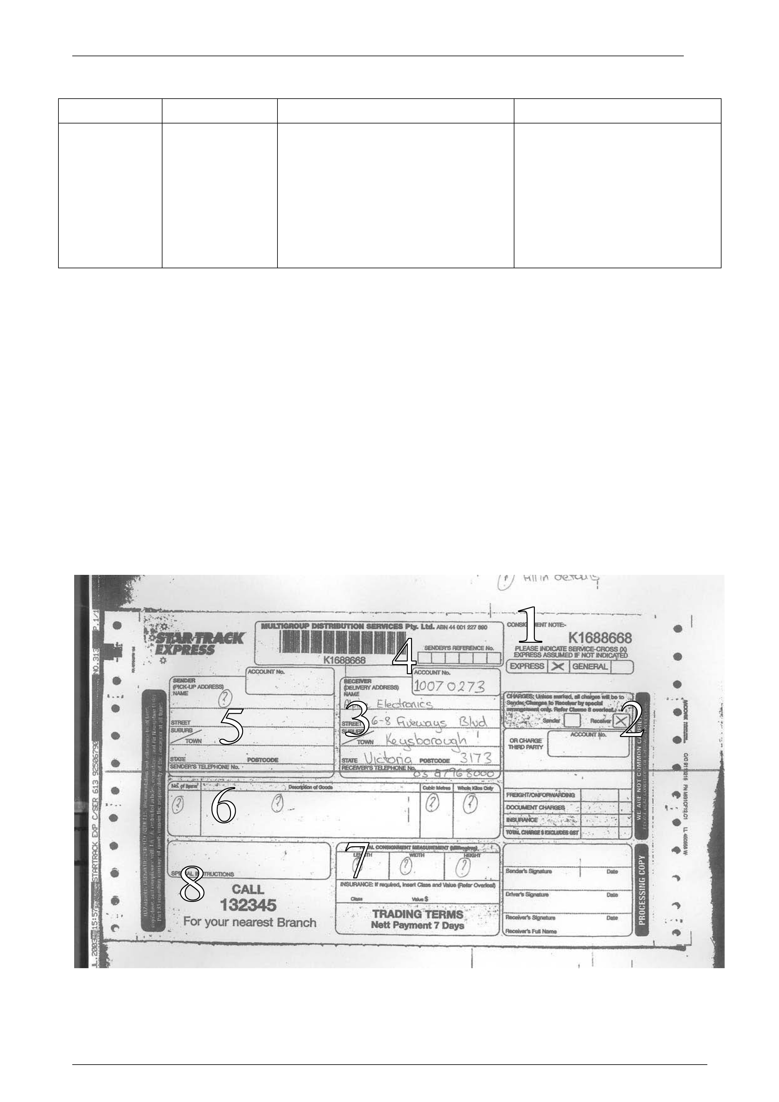
Carrier Details
Our choice of carrier for all returns is Startrack Express.
To ensure correct pick up phone Startrack on 13 23 45 and request a pick up. When callin g also request a consignment
note for Road Express to be bought along. The consignment note must be filled in with the following (refer Append ix B):
1. Alpine’s address: 6-8 Fiveways Boulevarde, Ke ysboroug h, Victoria, 3173.
2. Account number: 10070273
3. Cross the EXPRESS box under the consignment note number.
4. Fill in the dealerships details in the sen der box.
5. Cross the RECEIVER to pay box.
6. Fill in the measurements and sign/date.
7. Adhere to box and send.
PLEASE NOTE: Goods dispatched via any other carrier or dispatched via Startrack by any means other than Road
Express are not acceptabl e and costs incurred will be charged to the originating dealer.
Warranty Procedure
On receipt of a concern regarding any component the steps below need to be followed:
1. Confirm with the customer the actual fault noted. Please also include any unusual circumstances such as
temperature or what the system was being used for at the time the fault was noted.
2. Refer to the diagnostic chart included in the Repair Request Form.
3. Please check for scratches and damage to unit or fascia and note on form.
4. Fill in the Repair Request Form (fully), package the failed unit with the Repair Request Form into the correct
packaging (refer guidelines) and se nd to Alpine (as per guidelines).
5. On receipt of the failed unit, the unit will be checked to ensure the fail ure is due to a manufacturing or material
fault.
6. If this is the case the unit will be repaired and returned free of charge.
7. If this is not the case the servicing dealer will be contacted and quoted for the repair. Payment for this repair will
be required prior to the unit being returned.
8. The repair will be carried out as per the Al pine technical service manual for each product and the specifications
contained within.
9. The repaired unit will then be returned within 10 working da ys (from the units receipt) to the servicing dealer.
10. At this same time preparations will be made to reimburse the servicing dealer a set amount for the labou r time.
Refer to the guidelines for information. T he amount reimbursed will automatically include diagnoses with the
component sent for repair.

Page J-36
Alpine Contact Details
Dealers Procedure
1. Where a customer contacts a HSV dealer with a system related query the dealer can follo w the process outlined
below:
2. Attempt to answer the query over the phone.
3. If unable, the vehicle would b e prese nted to the dea ler to clarify the reported issue.
4. The dealer can then follow the Diagnoses Sheet to diagnose the reported issue.
5. If the dealer is having difficulty the d ealer can contact Alpine on 03 8796 8060.
6. This number can assist with general product queries and can als o provide access to specific problem solving
information.
7. Once diagnosed the dealer follows the warranty process.
Company: Alpine Electronics of Australia
161-165 Princes Highway
Hallam Victoria 3803
Main Phone: 03 8787 1200
Main Fax: 03 8787 1299
ABN 64 007444 368
ACN 007 444 368
Key Contact Jeff Dickson
Manager – Customer & Technical Services
Ph:03 8787 1250
Mob: 0403 045 386
Email: [email protected]
Logistics Geoff
Dennehy
Logistics Manager
Ph: 03 8787 1200
Email: [email protected]
Sales Anthony
Bell
Nat. Sales and Marketing Manager
Ph: 03 8787 1200
Mob: 0403 045 371
Email: [email protected]

Page J-37
Diagnoses Check Sheet
Product Symptom Check Action
All No operation Is ignition on / Battery charged If all O.K. check power
Has vehicle been jump started to each, Yellow/Red
Check fuse #16 in fusebox Are 12V, black is ground
DVD Player Wont accept Check car battery is charged If no power remove unit
or eject discs Check power to yellow wire and for service
ground to black wire at DVD
No operation Check Ignition on Using remote, press and
Check a disc is inserted hold V.OUT button for
Ensure monitor is on eight seconds. If this
Is the disc damaged or upside Does not work - remove
down
Poor picture Check disc is not NTSC or PAL Change setting on DVD
Check disc settings Remove if still poor.
Monitor No operation Check ignition is on Check power to module
Press power button on remote Red – power, Black -
whilst aiming at the monitor and ground
setting the remote to “Monitor” Check white/brown goes
Check fuse in module in boot to white/brown
Poor picture Check monitor is set to correct Remove for service
display – NTSC or PAL
Adjust set up functions
Won’t play Check disc is Region 4 or All
Check disc is right way up
Check video mode is correct -
NTSC or PAL setting
Check Purple DIN lead is
Connected from monitor to Remove for service
module
Radio Input Won’t turn on Check ignition is on Check Red- power,
Press POWER button Black –ground
Check Controller cable is
Plugged into module
Check Phone fuse (#16)
Wont play Check Set-up menu Check DVD stand-alone
discs Check AI-Net cable is function – if this is O.K.
connected to the Changer Remove Radio Input.
Page J-38
Product Symptom Check Action
Headphones No operation Check batteries If still not operational
Checked the power light is lit Remove for repair
Check the volume is up
Check there is audio playing
Ensure the monitor is open/on
Are the headphones in range
Items to note:
1. Mark Road Express ONLY
2. Mark Receiver to pay
3. Fill in delivery address as 6-8 Fiveways Boulevarde,
Keysborough, Vic, 3173
4. Fill in account number as 100 70273
5. Fill in your details as the Sender
6. Fill in the Description
7. Fill in the parcel details
8. Ring 132345
Page J-39
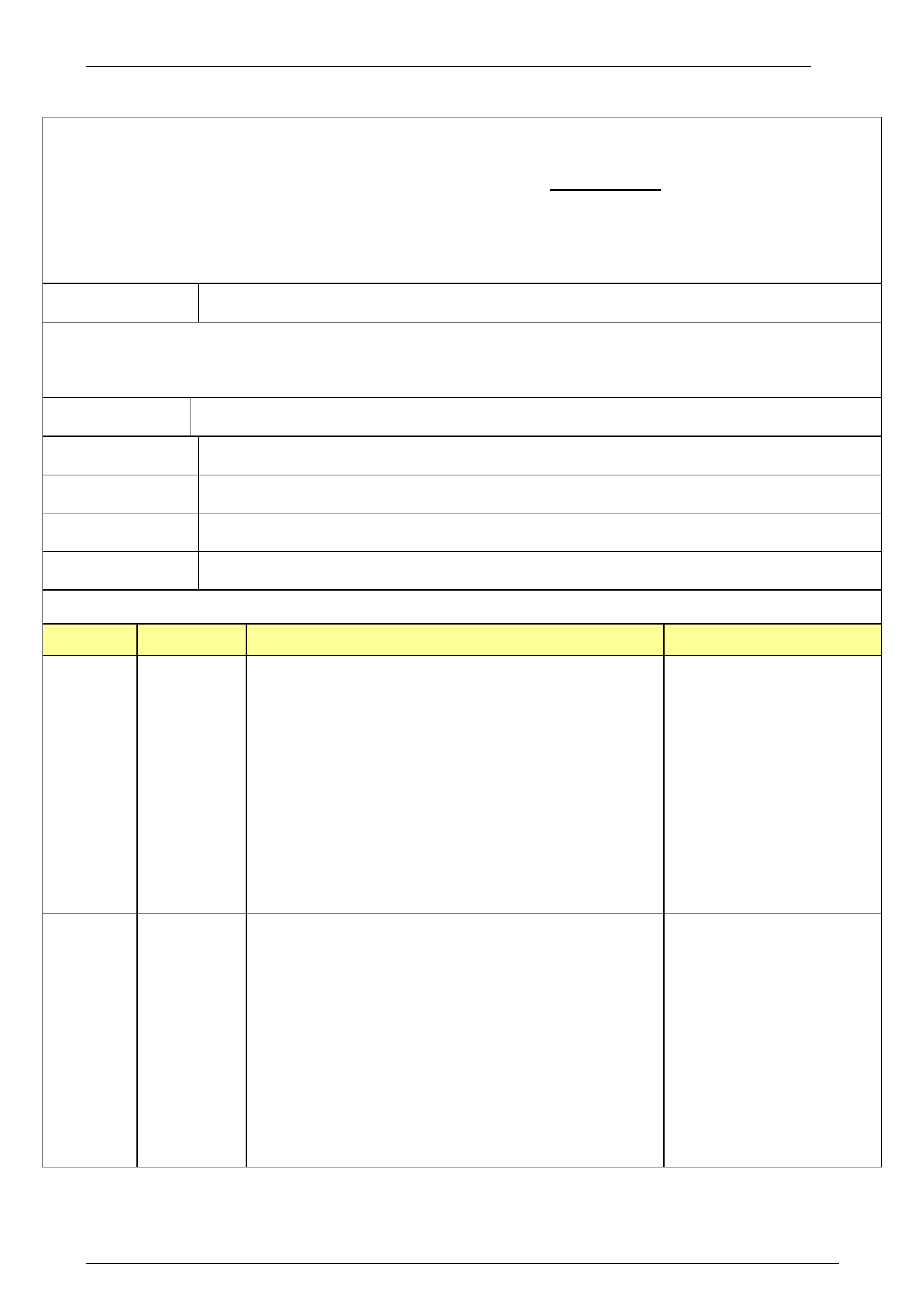
HSV DVD Entertainment System Repair Request Form
This sheet must be FULLY COMPLETED and supplied with the unit returned for repair
Return only via Startrack 13 23 45 - Request driver to supply a ROAD EXPRESS consignment note!
Fill in consignment note: Account number #10070273, Road Express, Receiver pays, No insurance
Send to: Alpine Electronics, 6-8 Fiveways Boulevarde, Keysborough, Vic 3173. Mark "FRAGILE".
Only for warranty repairs - Use of this service for non-warranty repairs will be charged
Date: Dealer Name:
Dealer Address:
Model No: Serial No# of suspect unit: (one letter & eight numbers)
Registration No: Chassis No:
Odometer: Owners Name:
Date of first reg: OR Date of Fitment: (Whichever is the latest)
VEHICLE MODEL: ALPINE CUSTOMER SERVICE PHONE: 03 8796 8060 FAX:03 9798 2984
PLEASE CIRCLE THE PRODUCT TYPE AND SYMPTOM
Product Symptom Pre-removal Check Action
Monitor No operation Check Ignition is on On removal please record the
No Picture Check monitor is open serial number in the space provided
Check remote is working and return this sheet with the failed
Confirm Alpine logo is showing in remote unit.
receiver window
Can you hear sounds with the Headphones
Check Fuse box fuse for the Phone connector
Check vehicles battery is measuring over 11 V
DVD Player No operation Check ignition is on If these steps do not resolve the
Open front panel - Eject the cartridge and refit issue please check the in-line fuses
Are the lights on the DVD player visible with and the cars fuses at the fuse box
the above steps (left kick panel).
Check the disc is a video disc If still unresolved record the serial
No Vision OR Remove the unit and confirm the RCA's and number on this sheet and return with
Sound the power connector is plugged in the failed component.
Check power to the 4-way connector Yel/Red

Page J-40
Product Symptom Pre-removal Check Action
Radio Input No operation Check the unit is on Remove the module/controller
Check Changer is selected
Check power to the module
Headphones No operation Ensure the H/P are on, batteries in, volume up Return the Headphones
Ensure the H/P are in front of the monitor to Alpine for service.
Fault Details: PLEASE BE SPECIFIC AS A NO FAULT FOUND RESULT WILL INCUR A $50 CHARGE.
BANK DETAILS FOR DIRECT TRANSFER (for payment of labour) Bank Name:
BSB No Account Number Account Name
Alpine Use Only JOB NO#
Warranty Invoice No#
Retail Con note # of unit received: Date
No Fault Found
Damaged Con note # for returned unit: Date