
Body Page B-1
Page B-1
Section B
Body
ATTENTION
HSV vehicles are equipped with a Supplemental Restraint System (SRS). An SRS consists of seat belt pre-
tensioners (fitted to all front seats), a driver’s-side air bag , a passenger’s-side air bag and left and right hand
side air bags. Refer to CAUTIONS, Section 12M, of the Holden WK Service Information before performing any
service operation on or around SRS components, the steering mechanism or wiring. Failure to follow the
CAUTIONS could result in personal injury or unnecessar y SRS system repairs.
1 Purpose................................................................................................................................................... 2
2 Seats ....................................................................................................................................................... 3
3 Body Components................................................................................................................................. 5
3.1 WK Grange 285 LS1 Sedan....................................................................................................................................5
Service Operations.................................................................................................................................................5
4 WK Rear Decklid Spoiler..................................................................................................................... 17
5 WK Radiator Grille............................................................................................................................... 18
Removal ................................................................................................................................................................18
Assembly ..............................................................................................................................................................18
6 WK Rear Décor Panel.......................................................................................................................... 21
Removal ................................................................................................................................................................21
Assembly ..............................................................................................................................................................21

Body Page B-2
Page B-2
1 Purpose
The purpose of this section is to provide information on the body and body components fitted to HSV WK vehicles. The
information is designed to supplement the information contained in the Holden W K Service Information, and details are
given where differences occur between the HSV models and standard Holden models. A series of instruction drawings
describe the design changes and indicate specific part numbers, fitting instructions and relevant notes for vehicle
servicing.
NOTE
If specific technical data on a HSV model is not
contained in this supplement, obtain data for that
model from the relevant Holden WK Service
Information Supplement. References are made
throughout this section to Holden Service
Information, to assist in providing information for
specific serv ice operati ons .
When hoisting (or jacking) HSV models,
ensure that the lifting head of the hoist lifts on
the chassis before the arm of the hoist
contacts the side-skirt
Body Page B-3
Page B-3
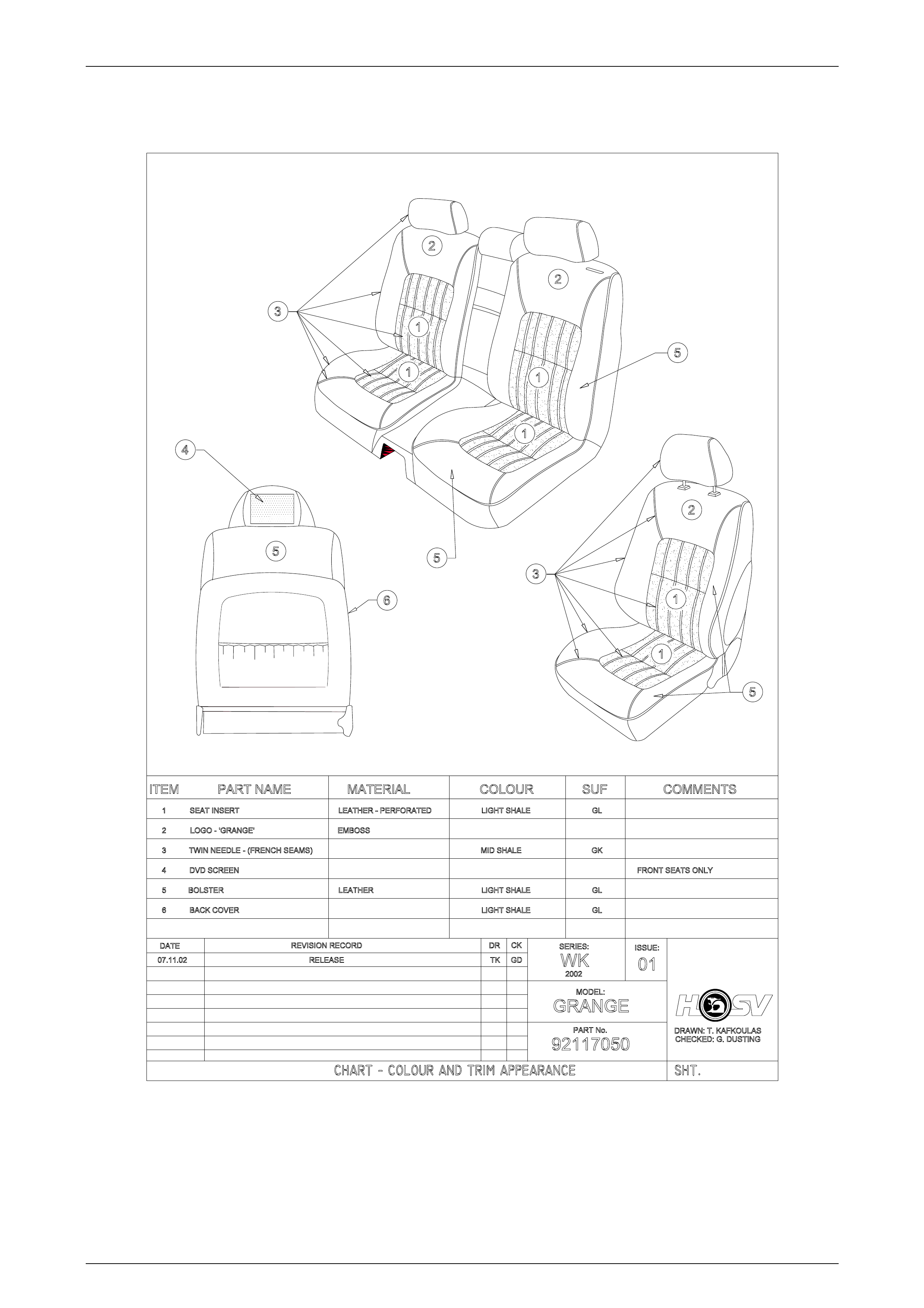
2 Seats
GRANGE
GRANGE GRANGE
SUEDE
Figure B-1 – Chart Colour and Trim Appearance
Body Page B-4
Page B-4
WK SEAT KITS - FRONT AND REAR SEAT
ASM
FRONT RH
SEAT
ASM
FRONT LH
BACK
ASM
REAR RH
BACK
ASM
REAR LH
CUSHION
ASM
REAR
SEAT
FLAP ASM
REAR
SEAT
BACK
BOLSTER
ASM RSB
RH
BOLSTER
ASM RSB
LH COLOUR
NK GL AB
(Blue) AD
(Red) AE
(Grey)
1 ONT- 92117050 WK GRANGE LEATHER SIAB 4100930 4100931 4100932 4100933 4100934 4100935 N/A N/A X
WK TRIM ASSEMBLIES –FRONT AND REAR TRIM
ASM
FSC RH
TRIM
ASM
FSC LH
TRIM
ASM
FSB RH
TRIM
ASM
FSB LH
TRIM
ASM FS
H/REST
RH
TRIM
ASM FS
H/REST
LH
TRIM
ASM
RSC
TRIM
ASM
RSB RH
TRIM
ASM
RSB LH
TRIM
ASM
RSB
H/REST
TRIM
ASM
RSB
FLAP
H/REST
TRIM
ASM
RSB
FLAP
TRIM
ASM
RSB
A
/REST
LID
TRIM ASM RSB
A/REST
COMPARTMENT
1 92117050 WK GRANGE LEATHER SIAB 4100898 4100897 4100958 4101036 4004233 4004233 4100968 4100970 4100969 4004733 4004740 4004750 4004755 4004226
WK FRAMES - FRONT AND REAR FRONT SEAT
CUSHION FRONT SEAT
BACK RH FRONT SEAT
BACK LH REAR SEAT
FLAP REAR SEAT CUSHION
92117050 WK GRANGE LEATHER SIAB 4003600 4004811 4004810 4002085 4004136
WK PADS - FRONT AND REAR FRONT
SEAT
CUSHION
FRONT
SEAT
BACK
FRONT
SEAT
HEADRES
T
REAR
SEAT
CUSHION
REAR
SEAT
BACK RH
REAR
SEAT
BACK LH
REAR
SEAT
HEADRES
T
CENTRE
HEADRES
T
REAR
SEAT
FLAP
REAR SEAT
A/REST
1 92117050 WK GRANGE LEATHER SIAB 4004149 4004146 4004120 4004161 4001874 4001875 4002172 4001884 4002938 N/A

Body Page B-5
Page B-5
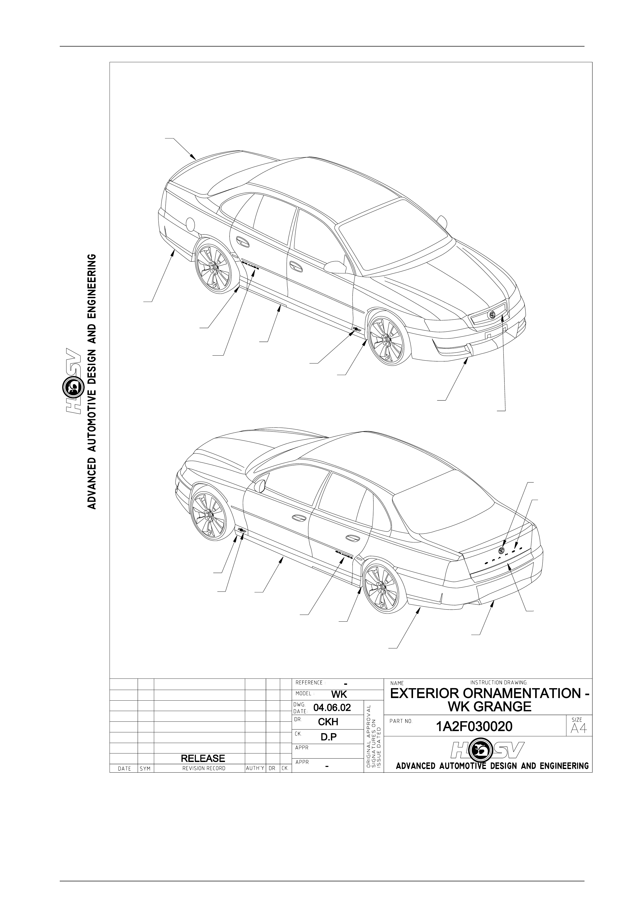
3 Body Components
3.1 WK Grange 285 LS1 Sedan
CONTENTS OF BODY STYLING PACKAGE
PART No QTY DESCRIPTIONS REF
A08-031304 1 SIDE SKIRT – ASSEMBLY – RH 1
A08-031303 1 SIDE SKIRT – ASSEMBLY – LH 2
14A2031307 1 REAR FACIA – CENTRE 3
14A2031305 1 REAR FACIA – LH 4
14A2031306 1 REAR FACIA – RH 5
E08-031301 1 SPOILER – REAR 6
E08-031305 1 PANEL REAR DECOR 7
A08-020604 1 PAINT PROTECTOR-SIDE SKIRT FRT RH 8
A08-020603 1 PAINT PROTECTOR-SIDE SKIRT-FRT LH 9
A08-020606 1 PAINT PROTECTOR-SIDE SKIRT-RR RH 10
A08-020605 1 PAINT PROTECTOR-SIDE SKIRT-RR LH 11
E08-031310B8 1 BADGE – GRANGE LH 12
E08-031310B8 1 BADGE – GRANGE RH 13
E08-031303B8 1 BADGE – GRANGE – REAR 14
E08-031307 2 BADGE – LION & HELME T 15
A08-020407B8 1 BADGE – CORPORATE LOGO – LH 16
A08-020407B8 1 BADGE – CORPORATE LOGO – RH 17
13C-031310 1 GRILLE RADIATOR ASSEMB LY 18
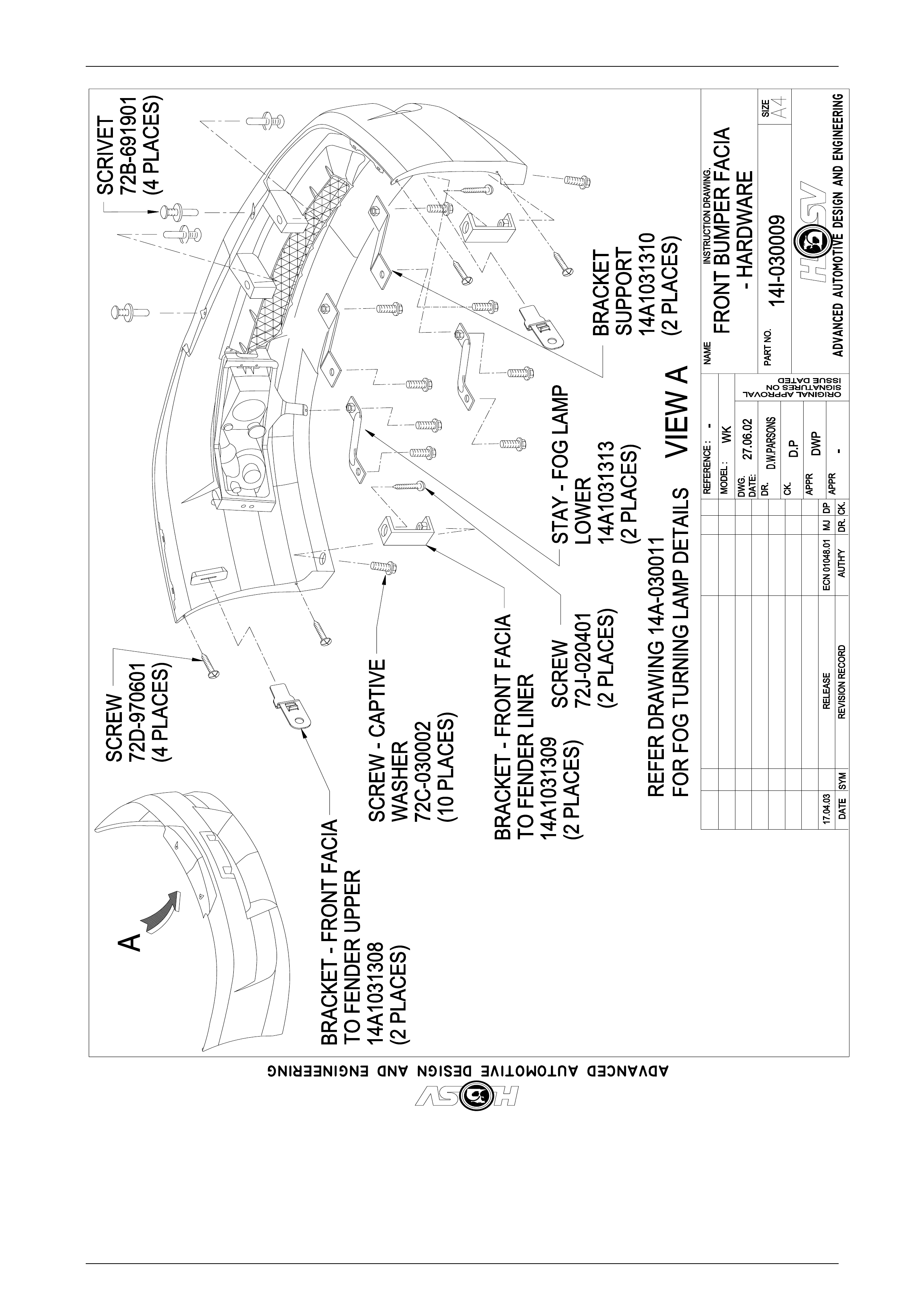
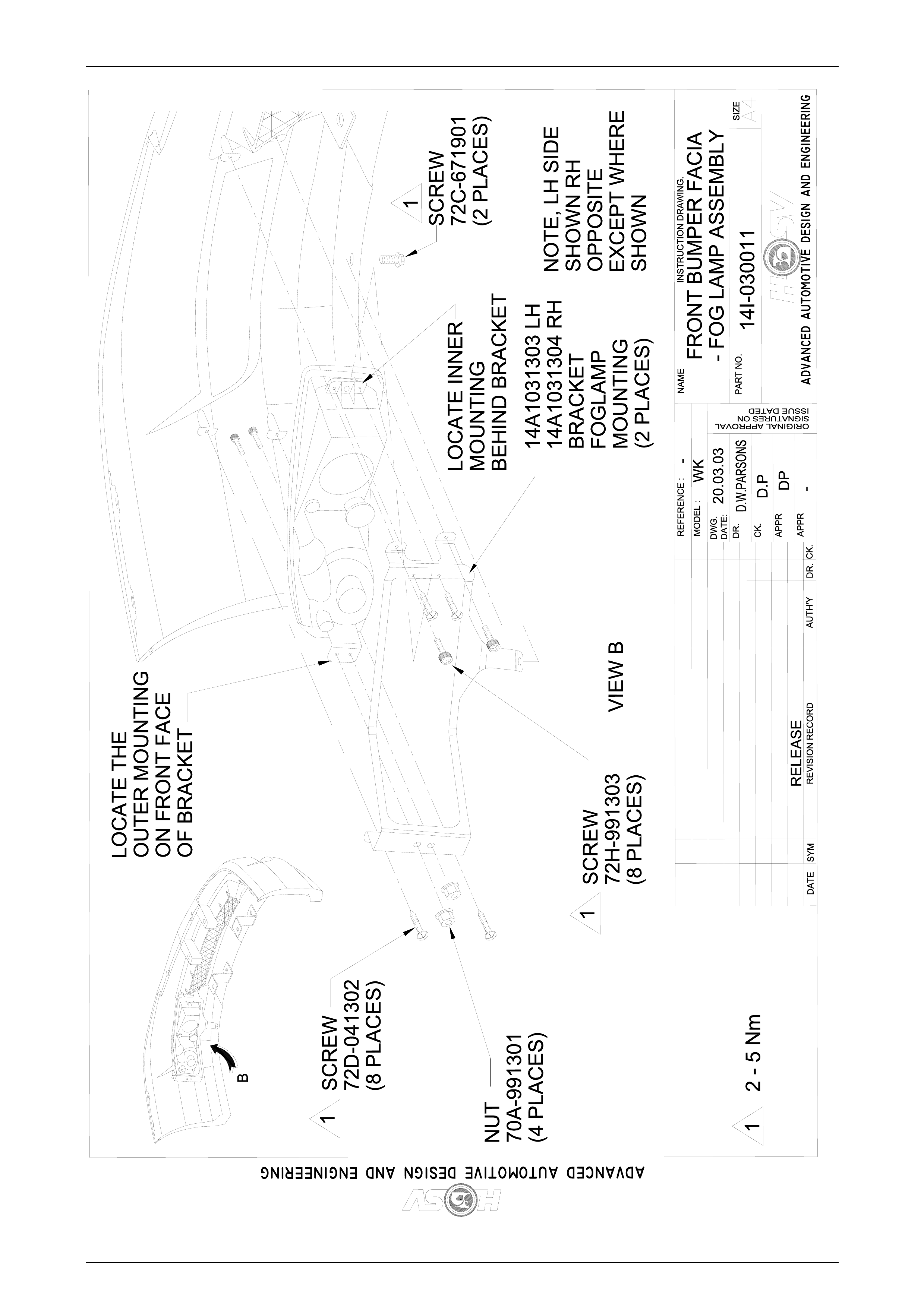
14A-1031301 1 FRONT FACIA 19
Service Operations
When servicing the WK Grange 285 Sedan Body Components, refer to the following drawings.
Body Page B-6
Page B-6
19 18
8
1
13
10
5
6
3
4
11
2
9
17
14
15
12
16
7
Body Page B-7
Page B-7
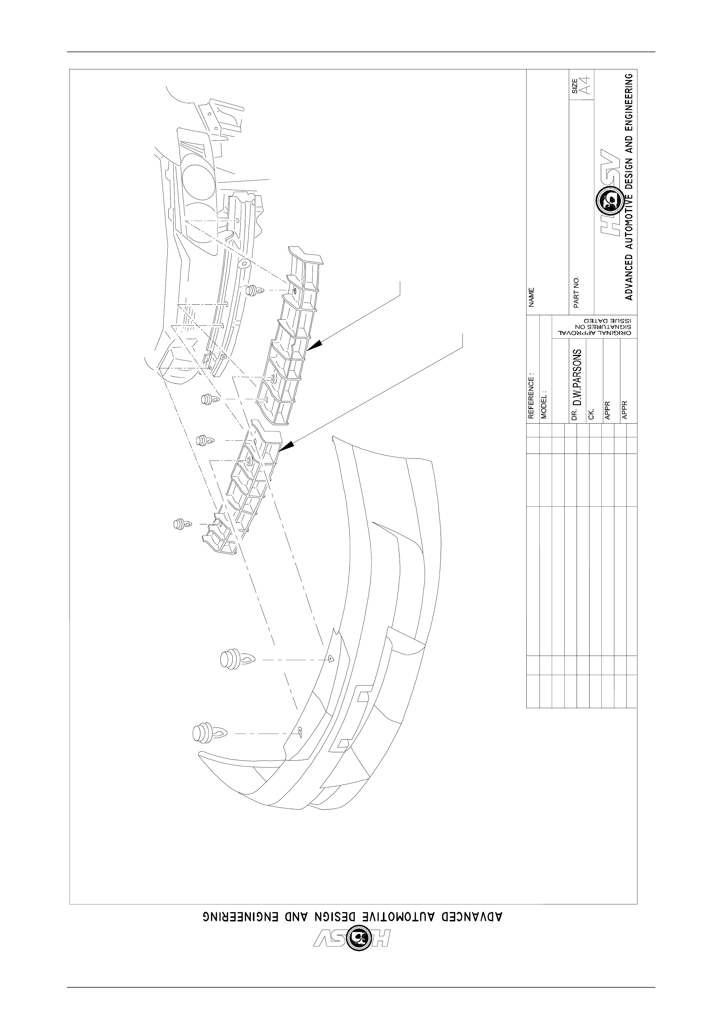
PAINT PROTECTOR - RHPAINT PROTECTOR -RH
14A1031306
LOWER GRILLE MESHLOWER GRILLE MESH
14A1031307
SCREWSCREW
72D-041701
(13 PLACES)
(13 PLACES)
1,0 - 3,0 Nm1,0 -3,0 Nm
1
1
FRONT BUMPER FACIA - WKFRONT BUMPER FACIA - WK
GRILLE & PAINT PROTECTORSGRILLE &PAINT PROTECTORS
14I-030012
DATEDATE SYM
SYM REVISIONRECORD
REVISION RECORD
DATE:
DATE:
DR.
DR.
AUTH'YAUTH'Y CK.
CK.
DWG.
DWG.
INSTRUCTIONDRAWING.
INSTRUCTION DRAWING.
DWP
D.P
27.06.02
WK
-
-
VIEW A
A
RELEASE
PAINT PROTECTOR - LHPAINT PROTECTOR -LH
14A103130514A1031305
Body Page B-8
Page B-8
Body Page B-9
Page B-9
Body Page B-10
Page B-10
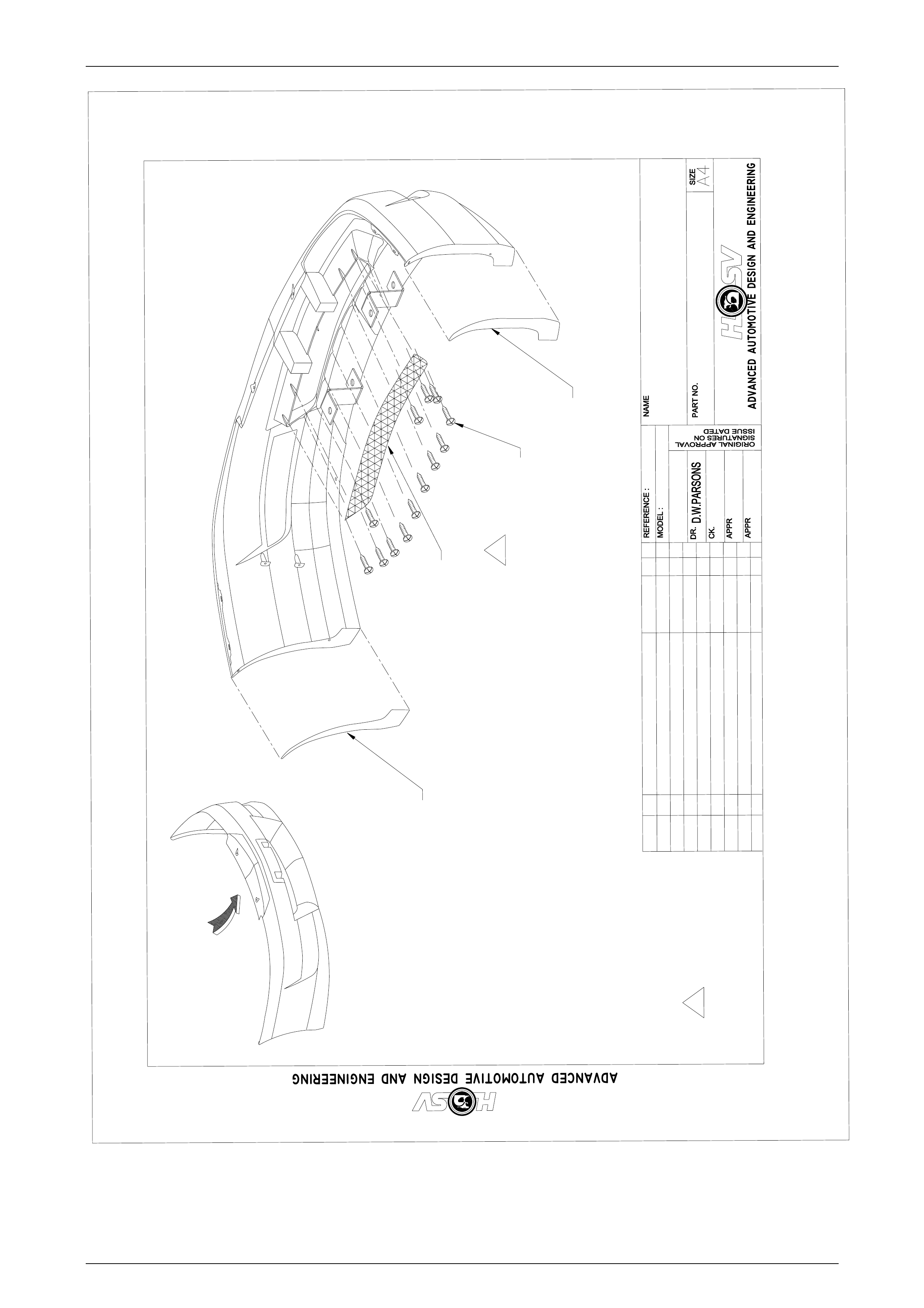
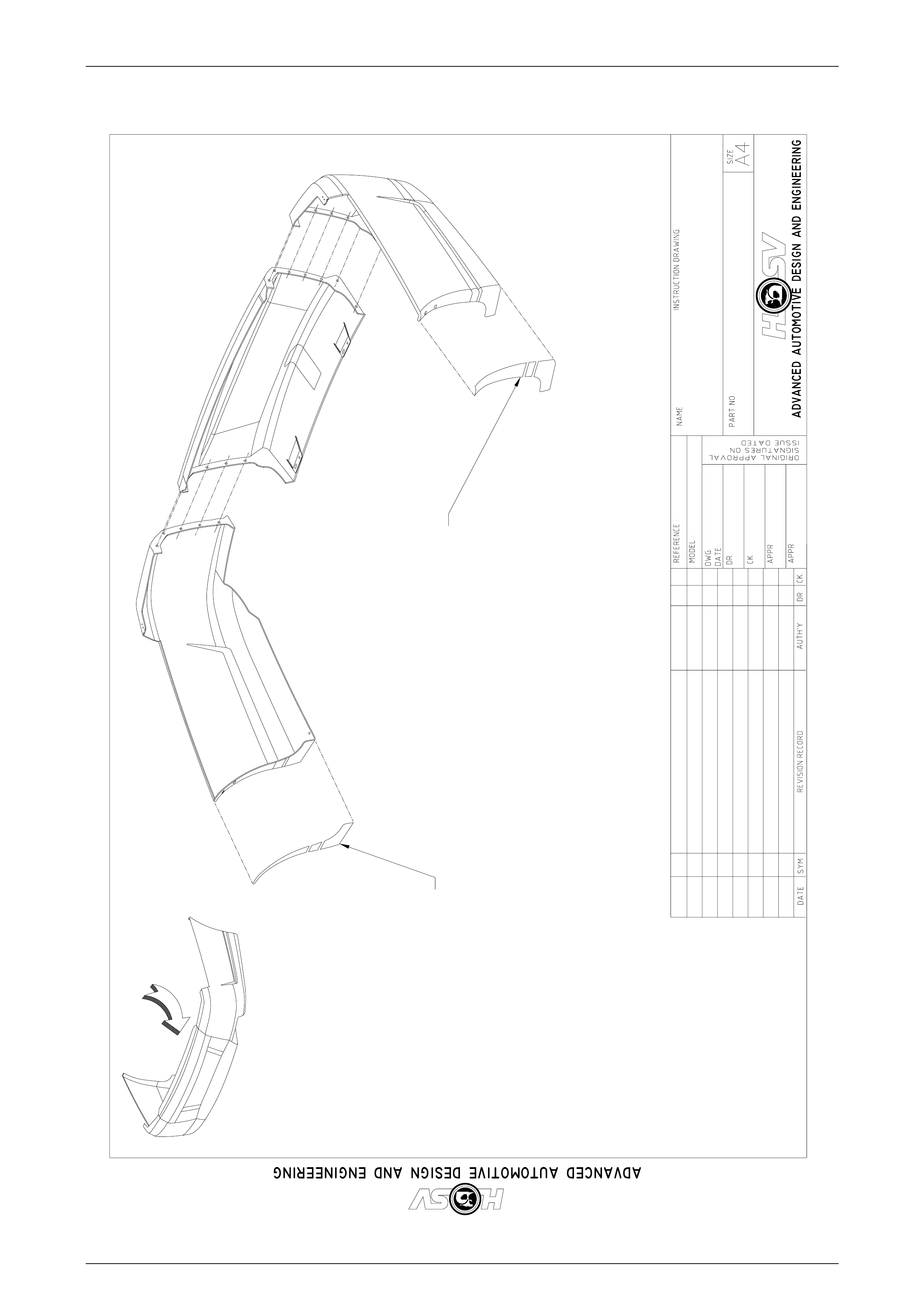
FRONT BUMPER
FACIA - REINFORCEMENT
14I-030020
DATE SYM REVISION RECORD
DATE:
DR.
AUTH'Y CK.
DWG.
INSTRUCTION DRAWING.
DWP
D.P
29.07.03
WK
-
-
RELEASE29.07.03 ECN 01048.01 MJ DP
14A1031311
SUPPORT - BUMPER FACIA
FRONT UPPER - LH
14A1031312
SUPPORT - BUMPER FACIA
FRONT UPPER - RH
Body Page B-11
Page B-11
RELEASE K.R.D
-
02.07.02
D.P
T.K
WK
-
REAR BUMPER FASCIA -
GRANGE - PAINTER PROD.
14I-020010
A
VIEW A
PAINT PROTECTOR
(3 PIECE)
14A1020608/LHS
PAINT PROTECTOR
(3 PIECE)
14A1020607/RHS
Body Page B-12
Page B-12
RELEASE
K.R.D
-
02.07.02
D.P
T.K
WK
-
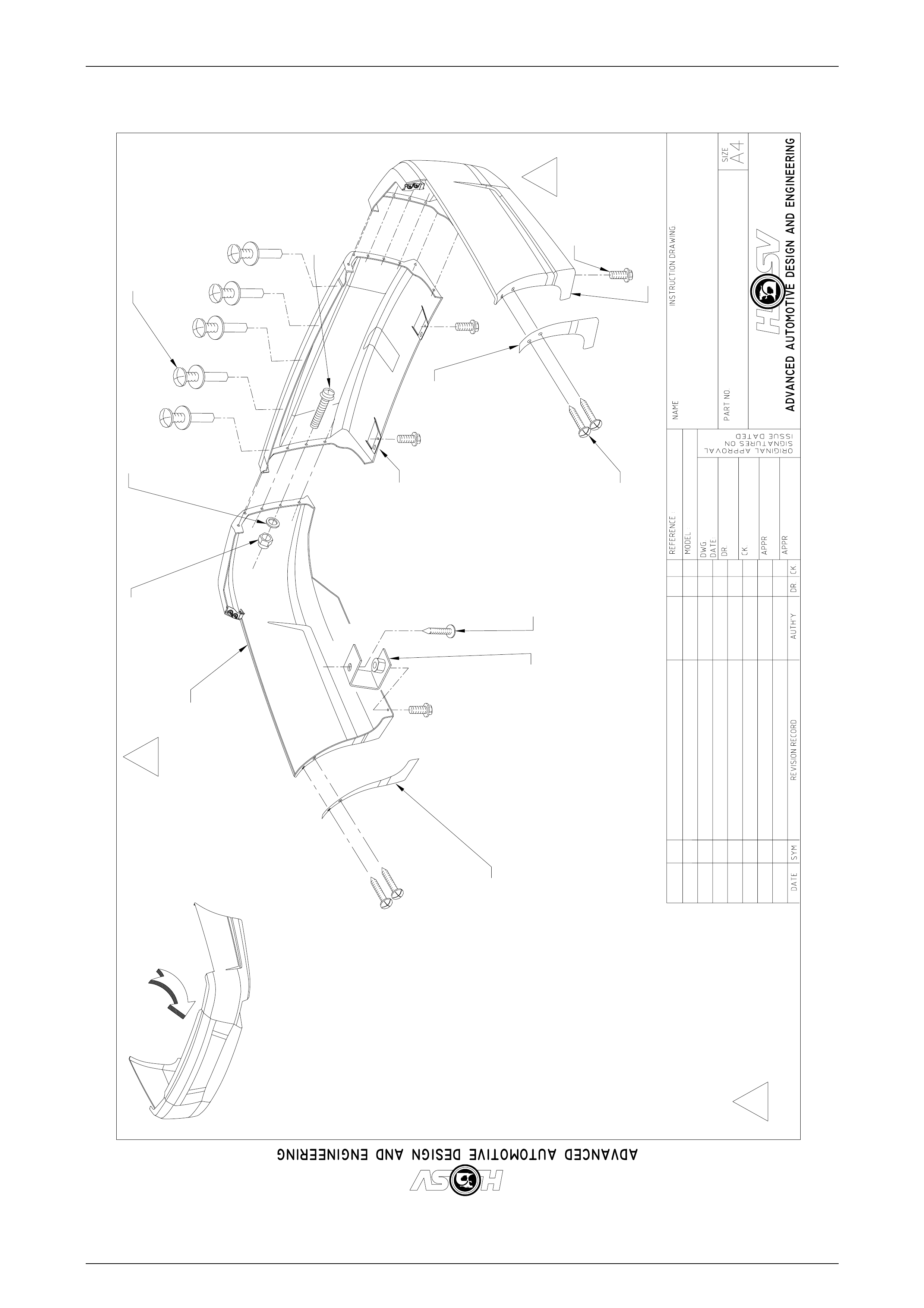
REAR BUMPER
FASCIA - GRANGE
14I-020009
A
VIEW A
72C-020009
(4 PLACES)
72D-970601
(4 PLACES)
71A-070201
(12 PLACES)
70B-060001
(12 PLACES)
73D-711905
(12 PLACES)
BRACKET
14A2031302
(2 PLACES)
SCREW
72J-020401
(2 PLACES)
SCRIVET
77B-691901
(8 PLACES)
17.04.03 ECN 01048.01 MJ DP
PAINT PROTECTOR
REAR - RH
14A2031310
(2 PLACES)
PAINT PROTECTOR
REAR - LH
14A2031309
(2 PLACES)
14A2031306
14A2031307
14A2031305
1
1
1 2-5Nm
Body Page B-13
Page B-13
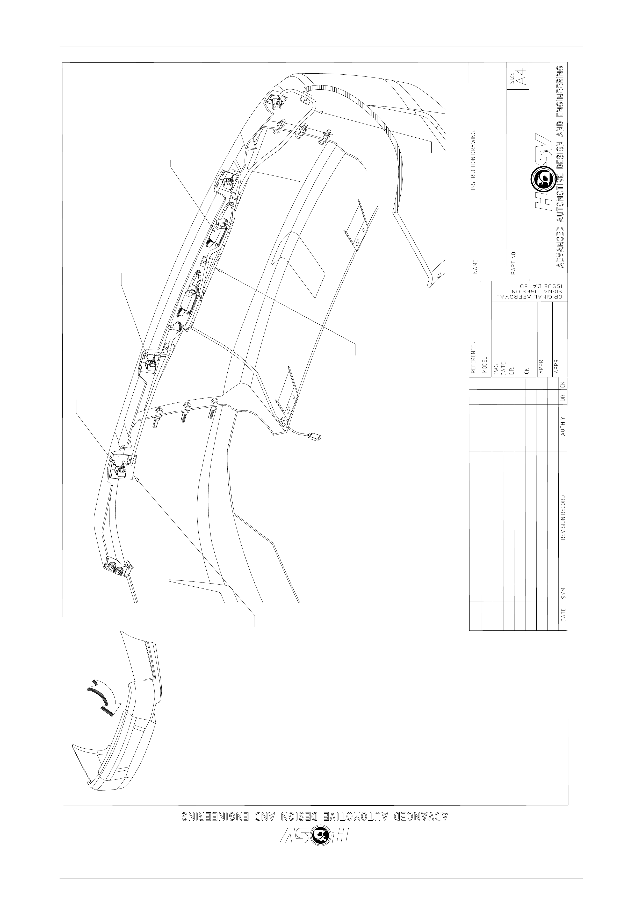
RELEASE
-
10.04.03
D.P
MJ
WK
-
HARNESS - NODSHARNESS -NODS
14I-030015
A
VIEW A
HOUSING - SENSORHOUSING -SENSOR
12F-001606
(4 PLACES)
(4 PLACES)
BRACKET - HOUSINGBRACKET - HOUSING
SUPPORT OUTER
14A-2001602
(2 PLACES)
(2 PLACES)
HARNESS RPAHARNESS RPA
12H-031301
BRACKET - HOUSING
BRACKET - HOUSING
SUPPORT INNER
14A-2031311
(2 PLACES)
(2 PLACES)
SENSOR
12F-021605
(4 PLACES)
(4 PLACES)
LAMP
92146298
(2 PLACES)
(2 PLACES)
LICENSE PLATELICENSE PLATE
LAMP HARNESSLAMP HARNESS
17.04.03 ECN 01048.01
ECN 01048.01 MJ DP
G.D
Body Page B-14
Page B-14
A
77B-970601
(9 PLACES)
(9 PLACES)
DATE REVISION RECORD
REVISION RECORD
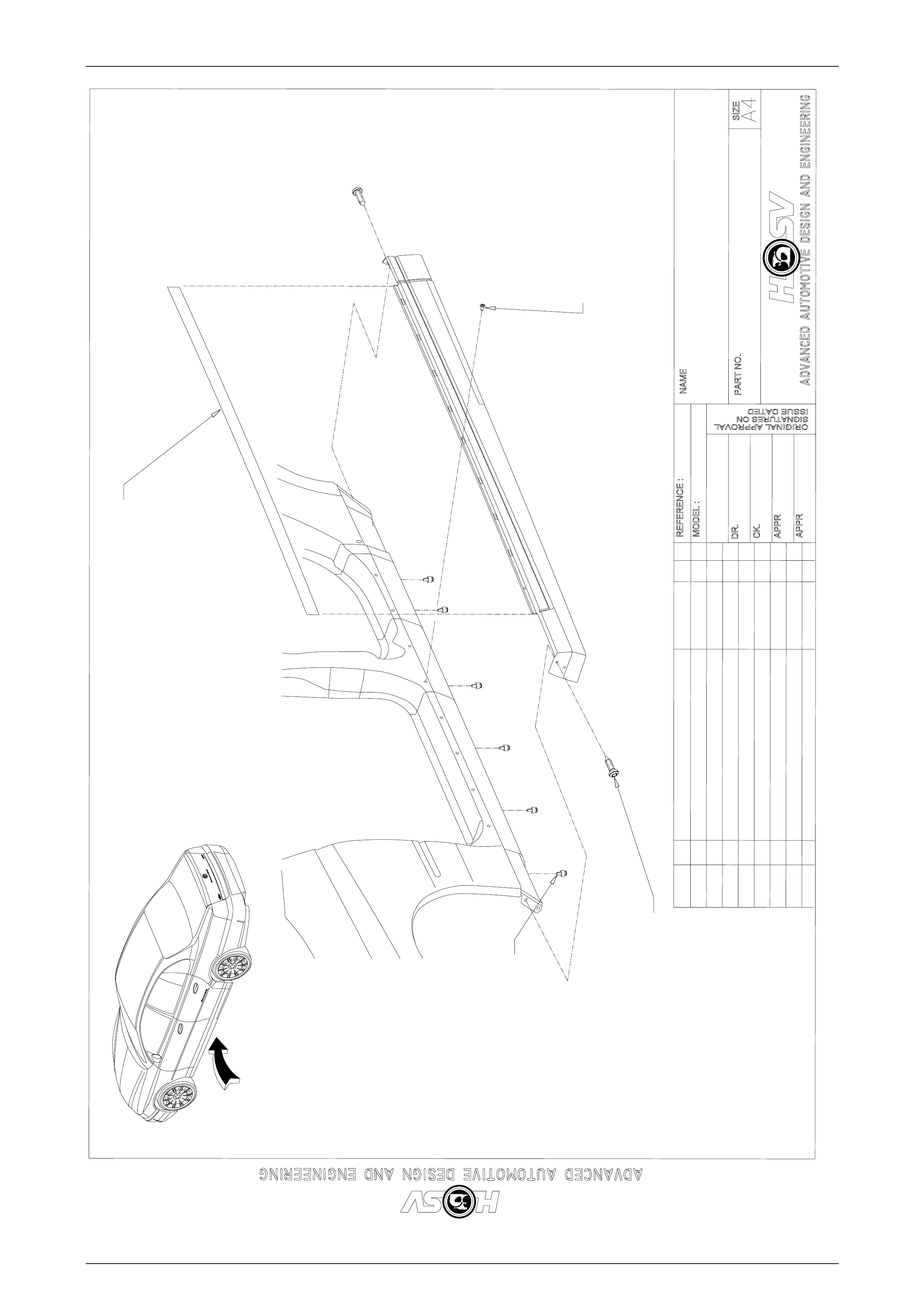
RELEASE
SYM DR.
AUTH'Y
AUTH'Y CK.
BRN
-
DWG.DWG.
DATE: 11.11.03
D.P
AP
WK
-
SIDE SKIRTSIDE SKIRT ASSEMBLYASSEMBLY
ATTACHMENT
14I-030021
INSTRUCTION DRAWING.INSTRUCTION DRAWING.
VIEW A
72D-041901
( 4 PLACES)
(4 PLACES)
72G-970302
( 6 PLACES)
(6 PLACES)
T213021102 SINGLET213021102 SINGLE
SIDED GASKETSIDED GASKET
TAPE. PART OFTAPE. PART OF
MOULDING
ASSEMBLY
ASSEMBLY
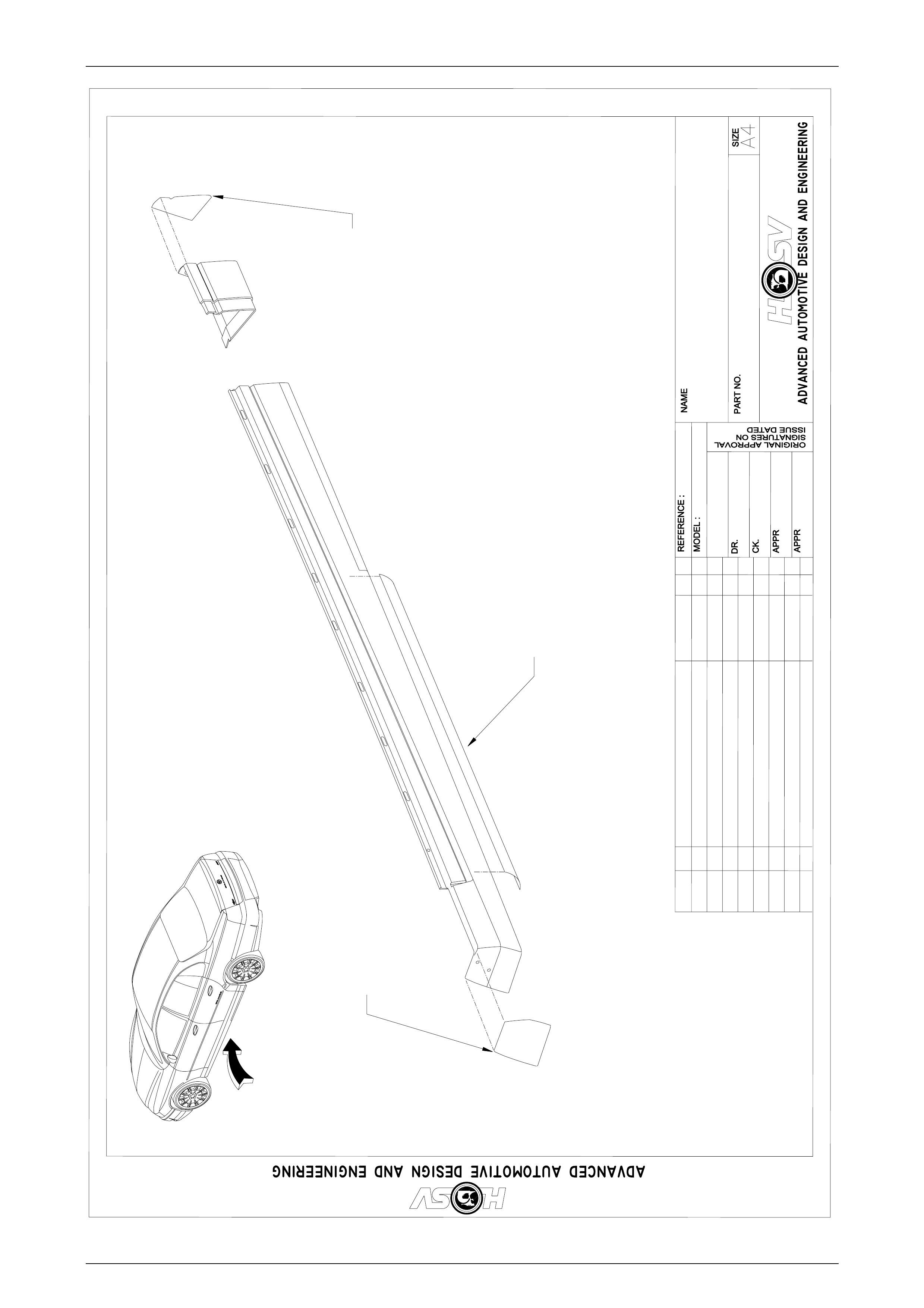
Body Page B-15
Page B-15
A
DATE REVISION RECORDREVISION RECORD
RELEASE
SYM DR.
AUTH'Y
AUTH'Y CK.
BRN
-
DWG.
DATE:
11.11.03
D.P
AP
WK
-
SIDE SKIRT ASSEMBLYSIDE SKIRT ASSEMBLY
14I-030019
INSTRUCTION DRAWING.INSTRUCTION DRAWING.
VIEW A
A08-020605
PAINT PROTECTORPAINT PROTECTOR
A08-020607
PAINT PROTECTOR
PAINT PROTECTOR
A08-020603
PAINT PROTECTOR
PAINT PROTECTOR
Body Page B-16
Page B-16
B
B
70A-991301
NUT
(3 PLACES)
(3 PLACES)
E08-020404E08-020404
SEAL
(3 PLACES)
(3 PLACES)
E0970602
GASKET
(3 PLACES)
(3 PLACES)
STUD
SPOILER
SPACER
77A-020401
STUD
(3 PLACES)
(3 PLACES)
71E-020201
SPACER
(3 PLACES)
(3 PLACES)
FOAM
SEAL
MIN. 20,0 mm STUD LENGTHMIN. 20,0 mm STUD LENGTH
APPLY LOCTITE 242APPLY LOCTITE 242
TO STUD PRIOR TO ASSEMBLYTO STUD PRIOR TO ASSEMBLY
1
12,0-5,0Nm
2,0 -5,0 Nm
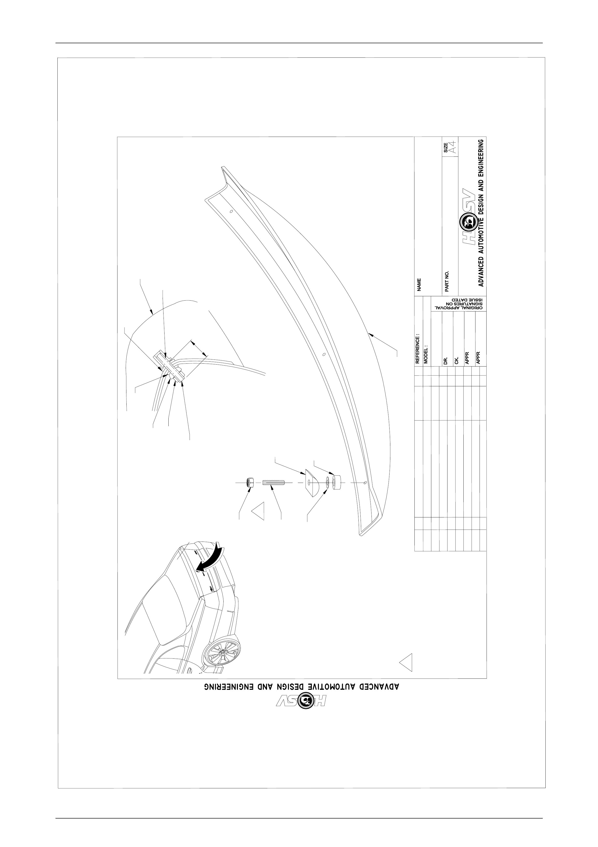
SPOILER
DATE REVISION RECORDREVISION RECORD
RELEASE
SYM DR.
AUTH'Y CK.
D.P
-
DWG.
DATE:
19.03.0319.03.03
D.P
D.W.PARSONS
WK
-
REAR DECKLID SPOILERREAR DECKLID SPOILER
E0I-020004
INSTRUCTION DRAWING.INSTRUCTION DRAWING.
A
VIEW AVIEW A
E08-031301
RUBBER
SEAL
SECTION THROUGHSECTION THROUGH
TYPICAL SPOILERTYPICAL SPOILER
ATTACHMENT
SECTION B-BSECTION B-B
NUT

Body Page B-17
Page B-17
4 WK Rear Decklid Spoiler
In the event that the rear deck lid requires replacement, a replacement decklid must be ordered through your local
authorised HSV dealer to ensure correct fitment of your body styling package.

Body Page B-18
Page B-18
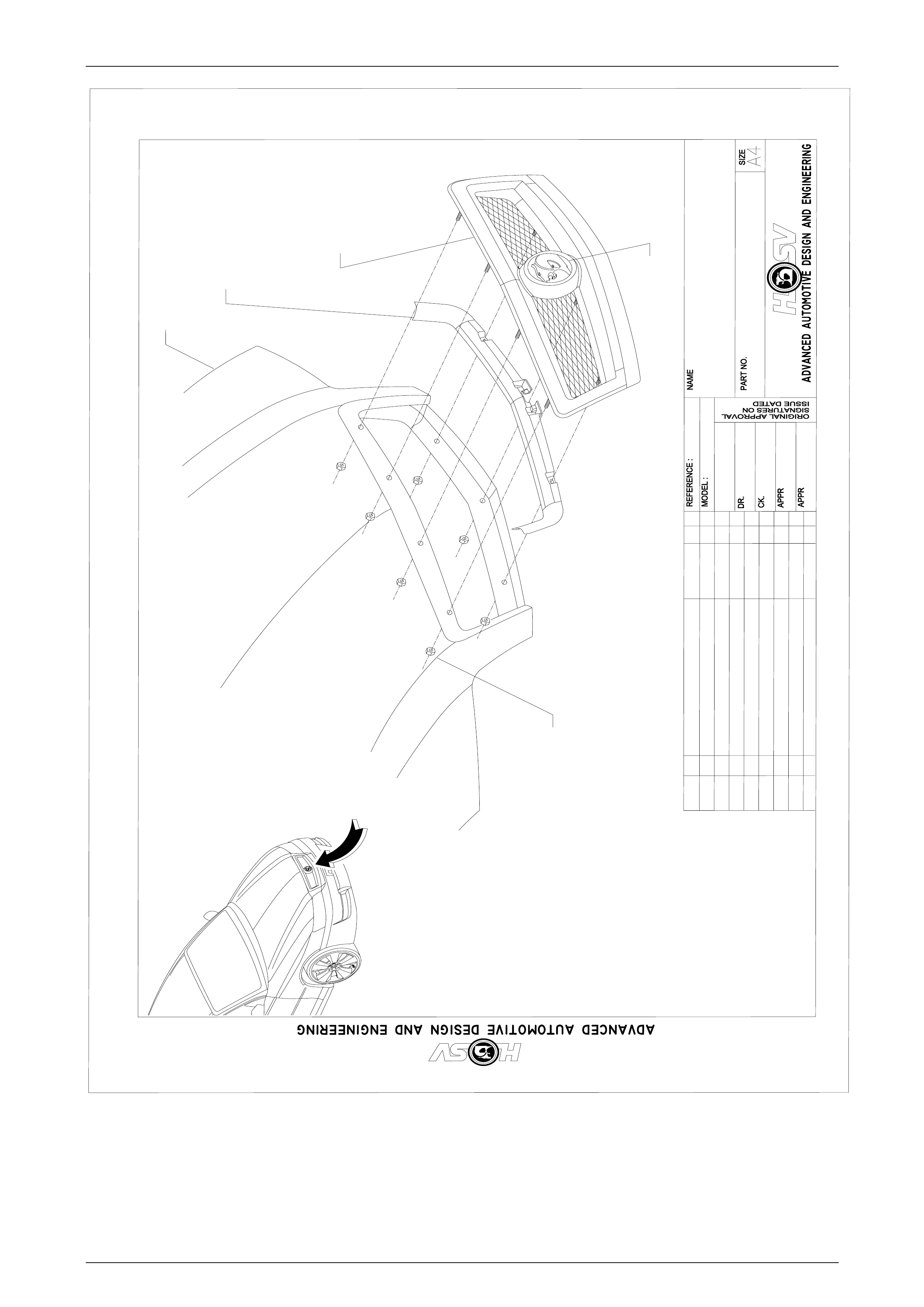
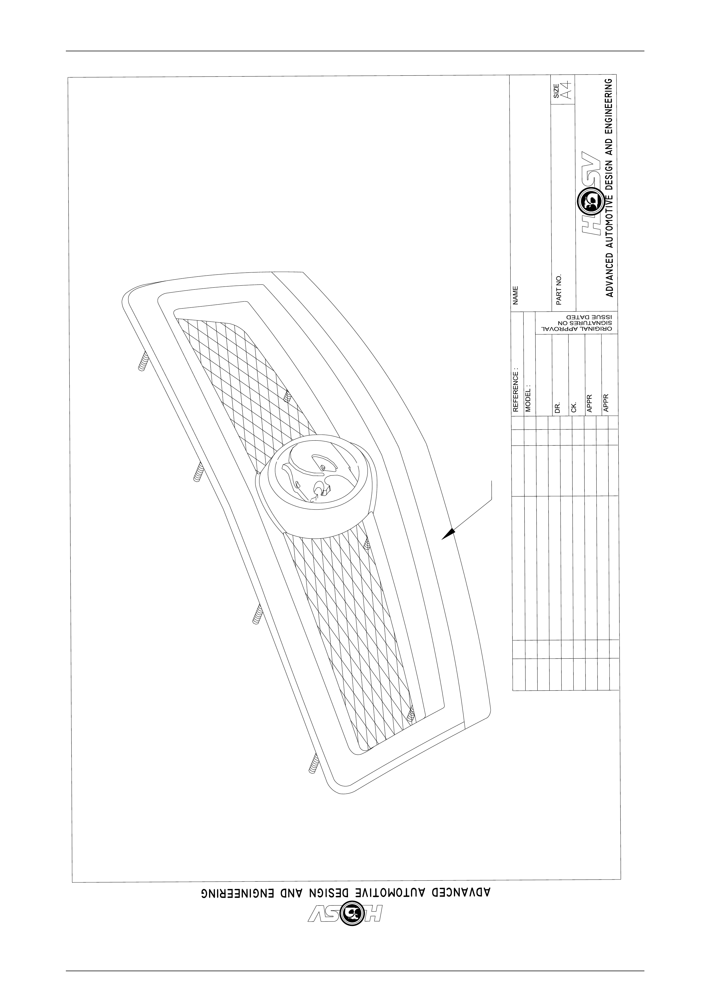
5 WK Radiator Grille
The Radiator Grille for the HSV WK Grange is a unique design, please refer to drawing number 13I-030001.
Removal
1. Open Engine Hood.
2. Loosen the 4 lower grille attaching nuts and washers.
3. Loosen and remove the upper outer attaching nuts and washers.
4. While supporting the sight shield, loosen and remove the upper inner attaching nuts and washers. Take care not to
dislodge the round spacers located on the center studs under the sight shield.
5. Lower the sight shield down the stud, this will give access to hold the spacer while the sight shield is removed.
6. Remove the sight shield.
7. Remove the spacer.
8. Remove the lower nuts and washers.
9. Remove the grille assembly from the hood panel.
Assembly
1. Using the centrally located guide pin assemble the grille into the engine hood recess 7 hood attaching holes
located in the grille recess.
2. Loosely attach both the LH & RH lower mounting nuts and washers.
3. Applying pressure on the RH bottom corner of the grille, gently push the grille upward in the hood recess and
tighten the RH lower nut (2.0 – 5.0 Nm).
4. Repeat this procedure on the LH bottom corner of the assembly.
5. Loosely assemble the spacers, sight shields, washers and nuts to the grille inner upper attaching studs.
6. Loosely assemble the washers and nuts to the outer upper grille studs.
7. Apply pressure to the to the RH top corner of the grille outer face to seat the grille into the hood recess while
torquing the attaching nut (2.0 – 5.0 Nm).
8. Repeat this procedure on the LH top corner of the assembly.
9. Torque up the center attaching nuts (2.0 – 5.0 Nm).
Body Page B-19
Page B-19
RELEASE
REVISION RECORD
REVISION RECORD
SYM
DATE
INSTRUCTION DRAWING.
INSTRUCTION DRAWING.
AUTH'Y
AUTH'Y
CK.
DR.
-
WK
T.K
D.P
10.07.02
DWG.
DWG.
DATE:
13I-030001
-
RADIATOR GRILLE
RADIATOR GRILLE
ASSEMBLY
ASSEMBLY
VIEW A
A
13C-031310
RADIATOR
GRILLE
70A-991301
NUT
(7 PLACES)
(7 PLACES)
11.07.02 ECN. O1186.03
ECN. O1186.03
E08-031307
BADGE
ENGINE
HOOD
13C-031306
SIGHT
SHIELD
Body Page B-20
Page B-20
RELEASE
REVISION RECORD
SYM
DATE
INSTRUCTION DRAWING.
AUTH'Y CK.
DR.
-
WK
DWP
DWP
19.03.02
DWG.
DATE:
-
RADIATOR GRILLE
PAINT
19.03.03 ECN. 01186.05
13I-030002
PAINT AREA BELOW PAINT GROOVE BODY COLOUR

Body Page B-21
Page B-21
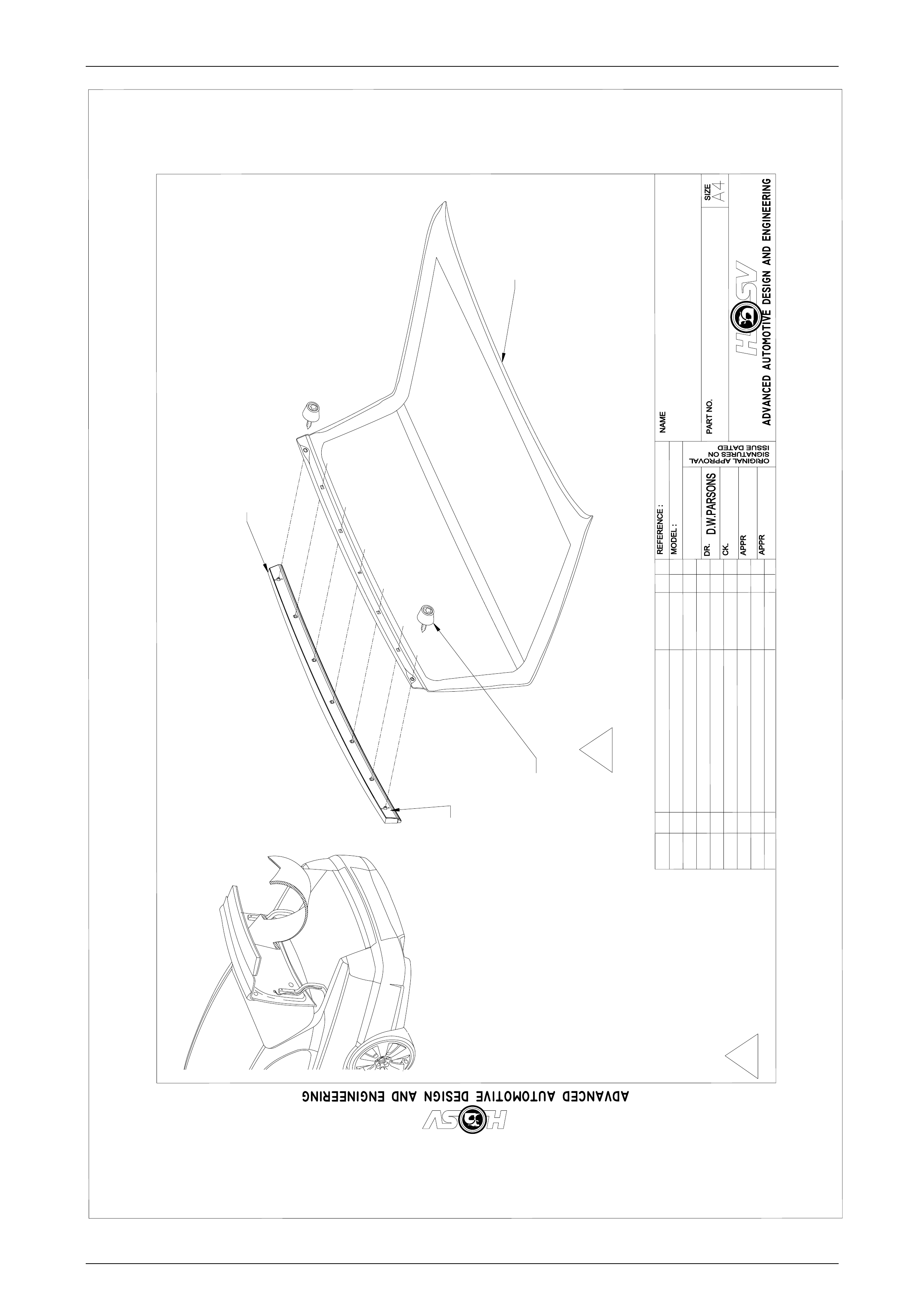
6 WK Rear Décor Panel
The Rear Décor Panel for the HSV WK Grange is a unique design, please refer to drawing number E0I-020005.
Removal
1. Open deck lid.
2. Remove the 2 end attaching screw and spacer assemblies. The Torx head screws and spacers locate against the
deck lid Inner panel.
3. Remove the rear compartment lid pull handle located on the LH side of the rear compartment lid inner panel, this is
a snap in part and is removed by pulling and rotating the handle down.
4. Remove the carpet retaining clips located along the bottom edge of the rear compartment lid.
5. Gently pull the carpet over the lock and switch, peal the carpet back to allow access to the inner panel.
6. Remove the rear compartment lock assembly. Refer to Section 1A4 Hood, Rear Compartment Lid, Liftgate and
Endgate of the Holden VY Service Information.
7. Using a suitable Phillips head screwdriver remove the center attaching screw for the décor panel. Care must be
used so as not to drop the screw into the cavity between the inner and outer panels.
8. Remove the décor panel from the rear compartment lid by lifting and rotating, care must be used not to damage the
panel surface.
Assembly
1. With the center attaching screw taped to a suitable Phillips head screwdriver insert the screw into the center
attaching hole in the compartment lid.
2. Offer the central attaching hole in the décor panel up to the exposed screw thread.
3. With the screw engaged in the décor panel tighten the screw 2 turns. This will assemble the screw temporarily to
the décor.
4. Clip the décor to the compartment outer panel while guiding the outer mounting bosses through their attaching
slots.
5. Install the outer mounting screw and spacers. Tighten the screw to a torque of 2.0 – 5.0 Nm.
6. Tighten the center attaching screw to 5.0 – 8.0 Nm. If a gap exists at its center between the décor and the outer
panel, tighten the center screw until the décor seats on the outer panel.
7. Care must be taken not to damage or dislodge the décor panel seal during the fitment of the parts.
8. Reassemble the lock and the carpet assembly. Refer to Refer to Section 1A4 Hood, Rear Compartment Lid,
Liftgate and Endgate of the Holden VY Service Information.
Body Page B-22
Page B-22
DATE REVISION RECORDREVISION RECORD
RELEASE
SYM DR.
AUTH'Y CK.
D.P
-
DWG.
DATE:
08/07/02
D.P
WK
-
REAR DECORE PANELREAR DECORE PANEL
E0I-020005
INSTRUCTION DRAWING.INSTRUCTION DRAWING.
VIEW AVIEW A
DECKLID
E08-031306
DECORE PANEL
DECORE PANEL
SEAL
E08-031305
DECORE PANEL
DECORE PANEL
72C-030001
SCREW & SPACER
SCREW &SPACER
ASSEMBLYASSEMBLY
(2 PLACES)(2 PLACES)
A
ECN 02068.03ECN 02068.03
1
11,4 - 1,8 Nm
1,4 -1,8 Nm