
Suspension Page C-1
Page C-1
Section C
Suspension
ATTENTION
HSV vehicles are equipped with a Supplemental Restraint System (SRS). An SRS consists of seat belt pre-
tensioners (fitted to all front seats), and a driver’s-side air bag AND a passenger’s-side air bag and left and
right hand side air bags. Refer to CAUTIONS, Section 12M, of the Holden WK Service Information before
performing any service operation on or around SRS components, the steering mechanism or wiring. Failure
to follow the CAUTIONS could result in personal injury or unnecessary SRS system repairs.
1 Purpose................................................................................................................................................... 2
2 Front Suspension .................................................................................................................................. 3
2.1 General Information...............................................................................................................................................3
2.2 Front Suspension Components............................................................................................................................4
Prestige Suspension..............................................................................................................................................4
2.3 Service Operations.................................................................................................................................................5
Front Wheel Alignment..........................................................................................................................................5
2.4 Service Intervals.....................................................................................................................................................6
3 Independent Rear Suspension............................................................................................................. 7
3.1 General Information...............................................................................................................................................7
3.2 Rear Suspension Components.............................................................................................................................8
Prestige Suspension..............................................................................................................................................8
3.3 Service Information................................................................................................................................................9
Service Information For Multi Link IRS................................................................................................................9
Rear Wheel Alignment...........................................................................................................................................9
4 Rear Axle............................................................................................................................................... 12
4.1 General Information.............................................................................................................................................12
4.2 Service Operations...............................................................................................................................................13
Torque Check .......................................................................................................................................................13
4.3 Limited Slip Differential.......................................................................................................................................14
Precautions...........................................................................................................................................................14
5 Propeller Shaft And Universal Joints................................................................................................. 15
5.1 General..................................................................................................................................................................15
5.2 Service Operations...............................................................................................................................................15
Techline
Suspension Page C-2
Page C-2
1 Purpose
The purpose of this section is to provide information on the front and rear suspension assemblies fitted to HSV WK
models. The information is designed to supplement the information contained in the Holden WK Service Information,
and details are given where differences occur between the HSV models and standard Holden models. A series of
instruction drawings describe the design changes and indicate specific part numbers, fitting instructions and relevant
notes for vehicle servicing.
NOTE
If specific technical data on a HSV model is not
contained in this supplement, obtain data for that
model from the relevant Holden WK Service
Information Supplement. References are made
throughout this section to Holden Service
Information, to assist in providing information for
specific service operations.
When hoisting (or jacking) HSV models,
ensure that the lifting head of the hoist lifts
on the chassis before the arm of the hoist
contacts the side-skirt

Suspension Page C-3
Page C-3
2 Front Suspension
2.1 General Information
The front suspension assembly fitted to HSV WK model is based on the Holden ‘MacPherson Strut’ design. All HSV W K
Grange struts have Monroe Sensatrac. This basic assembly (and the rear assembly) is then modified by HSV to provide
a suspension system more suited to the requirements of the HSV vehicle.
HSV SUSPENSION SYSTEMS
MODEL: SPORT PERFORMANCE LUXURY PRESTIGE
Grange S
Table-1

Suspension Page C-4
Page C-4
2.2 Front Suspension Components
The following components are fitted to front suspension assemblies as indicated:
Prestige Suspension
03C-970301 Spring - Front Suspension
03F-031601 Strut Asm Frt - LH
03F-031602 Strut Asm Frt - RH

Suspension Page C-5
Page C-5
2.3 Service Operations
Service front suspension assemblies fitted to HSV models in accordance with the relevant Holden WK Service
Information. Additional service requirements for specific HSV suspension assemblies are detailed in succeeding
paragraphs.
Safety and Cautionary nmte for vehicles
equipped with ABS
Whenever any component that forms a part of
the ABS is disturbed, it is vital that the
complete ABS system is checked. Refer to
Section 5B – ABS & ETC of the Holden WK
Service Information.
The tyre life of high performance low-profile tyres fitted to HSV W K vehicles is very sensitive to the toe-in setting of the
front suspension. It is crucial therefore, that care is taken to set the toe-in accurately to the correct specification.
Front Wheel Alignment
The front wheel alignment specification for WK vehicles is:
Toe-In
Degrees Total 0°10' ± 0°10'
Degrees Per Wheel 0°05' ± 0°5'
Camber & Caster
Camber -0°30' ± 0°10'
Caster 7°45' ± 1°15'
The toe-in specification is deliberately quoted as an angle because wherever possible toe-in should be measured in
degrees.


Suspension Page C-7
Page C-7
3 Independent Rear Suspension
3.1 General Information
Rear suspension assemblies fitted to HSV models are detailed in the Front Suspension, paragraph 1: these assemblies
have been developed to satisfy the various applications of the range of HSV models described in that paragraph. Level
ride shock absorbers are gas pressurised.

Suspension Page C-8
Page C-8
3.2 Rear Suspension Components
The following components are fitted to rear suspension:
Prestige Suspension
04B-031301 Spring Rear Suspension
04E-031601 Shock Absorber – Rear Suspension
04F-970301 Bar – Rear Stabiliser (16 mm)
04E-970809 Link Height Sensor (Sed 70mm)
Suspension Page C-9
Page C-9
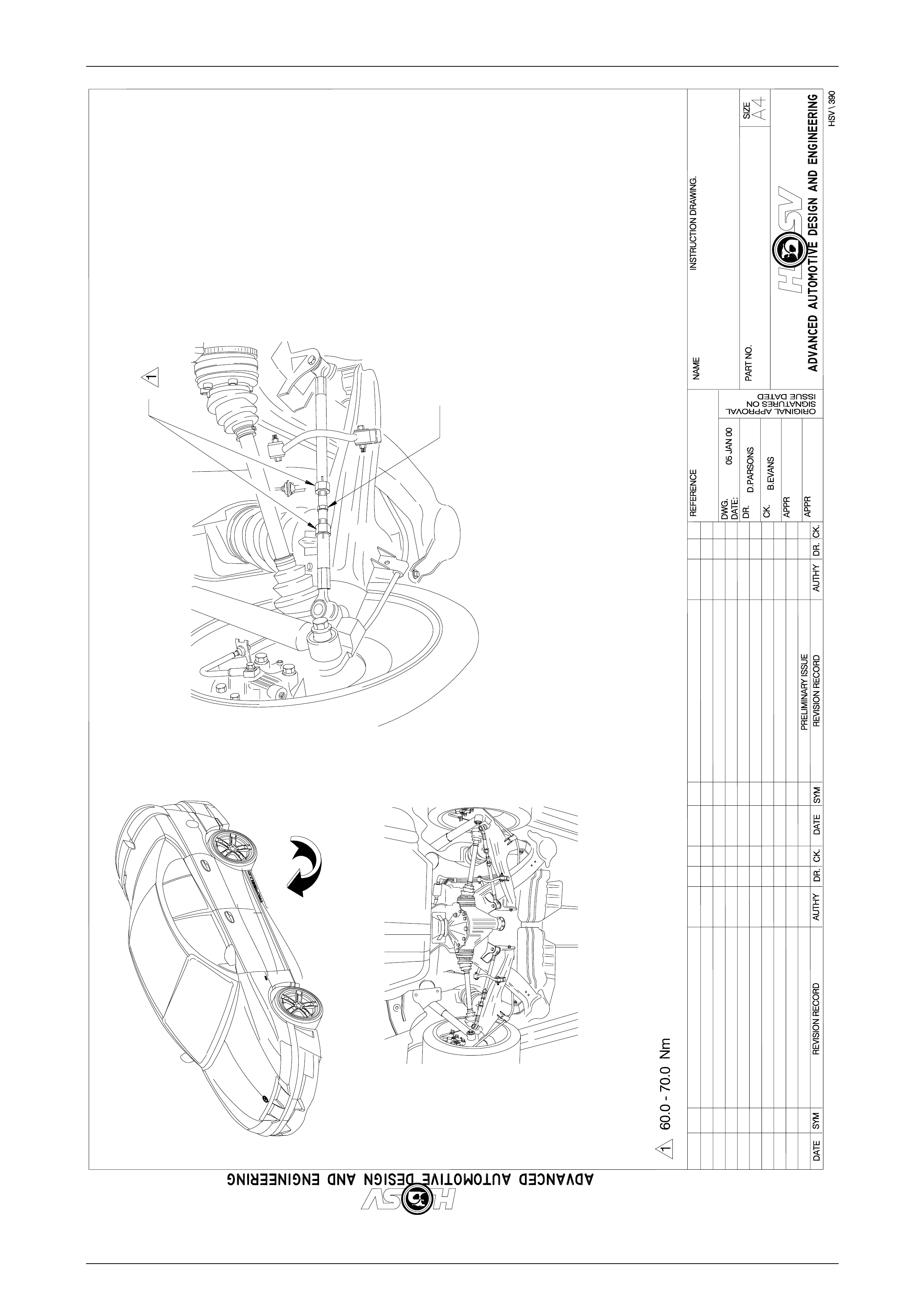
3.3 Service Information
Service Information For Multi Link IRS
Refer Figure: 04I-020004.
Rear Wheel Al i gnment
Rear suspension geometry should be set within the limits specified:
Toe-In
Toe Degrees per wheel 0o00’ to 0o15’
Variation side-to-side 0o10’ maximum.
Positive degrees indicates toe in.
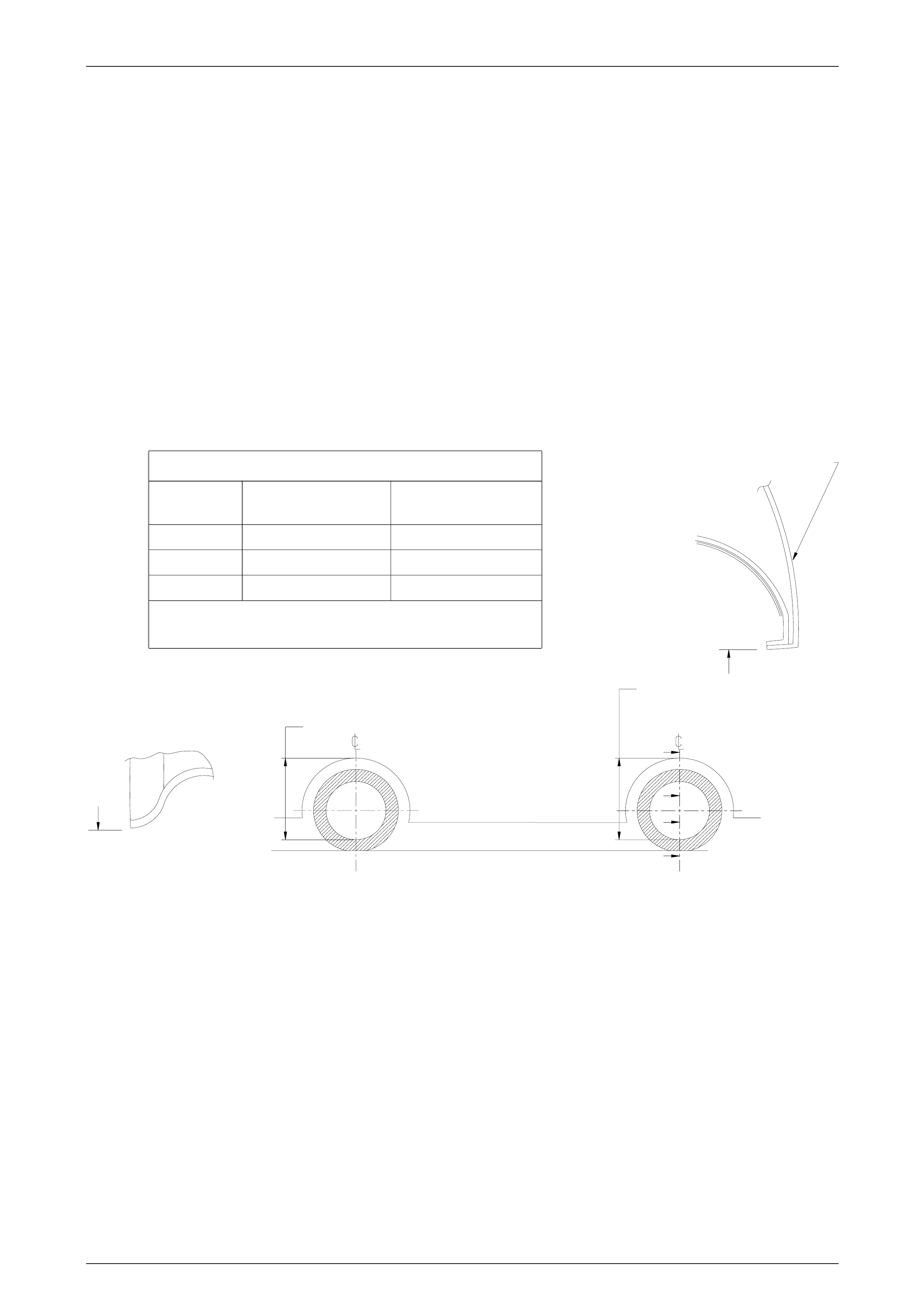
Conditions for vehicle set-up are as specified for Holden WK models. For HSV height information for the WK refer
diagram below.
MEASURE SUSPENSION HEIGHT
MEASURE SUSPENSION HEIGHT
FROM UNDERSIDE OF WHEEL ARCH
FROM UNDERSIDE OF WHEEL ARCH
TO LOWER POINT OF WHEEL RIM
TO LOWER POINT OF WHEEL RIM
B
B
A
A
SECTION A-A
SIDE PANEL OUTER
SIDE PANEL OUTER
SECTION B-B
SECTION B-B
MODEL
WHEEL SIZE
FRONT
REAR
WK
19"X8"
19" X8"
VEHICLE SUSPENSION HEIGHT AT KERB WEIGHT
VEHICLE SUSPENSION HEIGHT AT KERB WEIGHT
Suspension Height Measurements in mm.
Suspension Height Measurements in mm.
Kerb weight = Base weight + full tank of fuel
Kerb weight =Base weight + full tank of fuel
WK
628±5
628 ± 5
637±5
637 ± 5
18"X8"
18" X8"
642±5
642 ± 5
650±5
650 ± 5
FRONT SUSPENSION HEIGHT
FRONT SUSPENSION HEIGHT
REAR SUSPENSION HEIGHT
REAR SUSPENSION HEIGHT
Suspension Page C-10
Page C-10
A
VIEW A
LOCK NUTS
LOCK NUTS
TOE SETTINGTOE SETTING
ADJUSTER
MULTI LINK
MULTI LINK
ARM DETAILARM DETAIL
REAR TOE 0° ± 1mm (0° ± 0° 10 mins)REAR TOE 0° ± 1mm (0° ± 0° 10 mins)
04I-020004
REAR SUSPENSIONREAR SUSPENSION
MULTI - LINKMULTI -LINK
Suspension Page C-11
Page C-11
advanced automotive design and engineeringadvanced automotive design and engineering
DATE SYM
RELEASE
REVISION RECORD
REVISION RECORD
advanced automotive design and engineeringadvanced automotive design and engineering
-
REFERENCE :REFERENCE :
VY
11.04.03
MJ
D.P
DR.DR.
AUTH'YAUTH'Y
APPR
CK.
-
DR.DR.
APPR
CK.
CK.
DWG.
MODEL :
MODEL :
DATE:
SIGNATURES ONSIGNATURES ON
ISSUE DATEDISSUE DATED
ORIGINALAPPROVALORIGINAL APPROVAL
NAME
PART NO.
INSTRUCTIONDRAWING.
INSTRUCTION DRAWING.
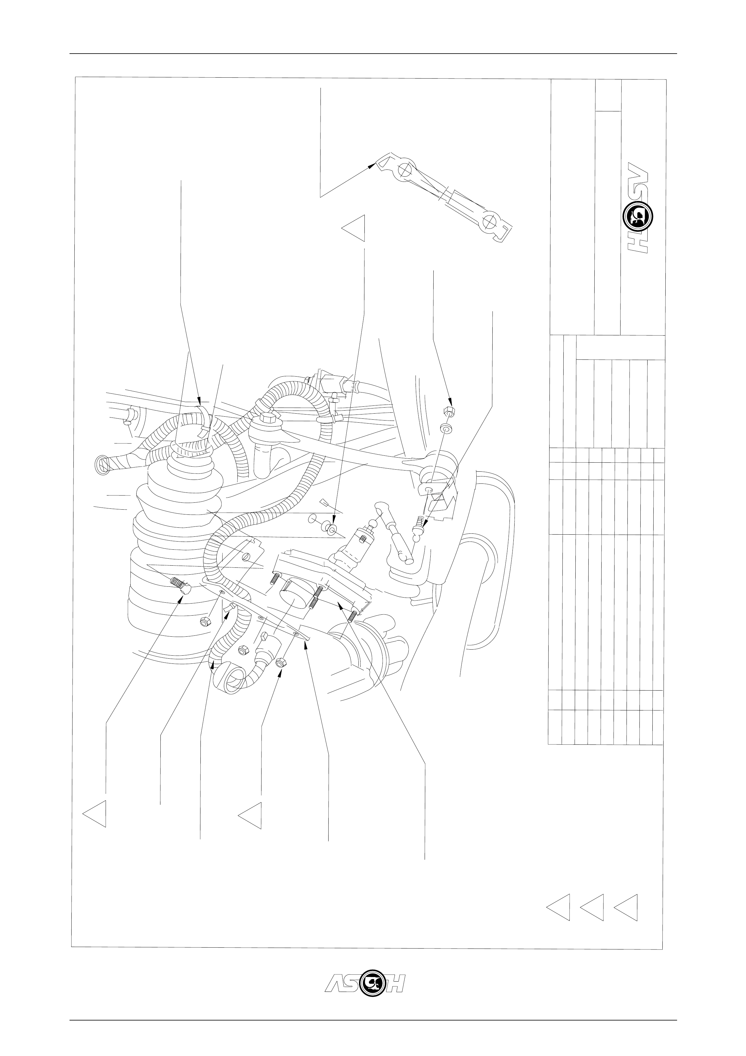
04I-020005
SIZE
A4
HSV LEVEL
HSV LEVEL RIDE
HEIGHT SENSOR
17.04.03 ECN 02086.01
ECN 02086.01 MJ DP
G.D
75C-180501(REF ONLY)75C-180501(REF ONLY)
CALBE TIE (3 PLACES)CALBE TIE (3 PLACES)
04E-970809 (SEDAN -- 70 MM)04E-970809 (SEDAN -- 70 MM)
LINK HEIGHT SENSORLINK HEIGHT SENSOR
*
70B-060001
NUT NYLOC
70G-080002
NUTSERT
UNCLIP END COVERUNCLIP END COVER
04E-970803
BRACKET BALL STUD
BRACKET BALL STUD
73A-082088
BOLT
75C-180501
CABLE TIE
SENSOR HARNESSSENSOR HARNESS
70B-050001
NUT NYLOC
(3 PLACES)
(3 PLACES)
04E-970802
BRACKET HEIGHT SENSOR
BRACKET HEIGHT SENSOR
04E-970807
HEIGHT SENSOR ASM
3
2
1
3-8Nm
3-8Nm
15 - 30 Nm15 -30 Nm
10 - 20 Nm10 -20 Nm
2
3
1

Suspension Page C-12
Page C-12
4 Rear Axle
4.1 General Information
The HSV W K model is equipped with a Hydratrak Differential (a specifically designed Viscous coupling type limited slip
differential).
Automatic transmission LS1 vehicles’ final drive ratio is 3.07:1 and the differential (Part No. 9205342) can be identified
by Broadcast Code EH.
Suspension Page C-13
Page C-13
4.2 Service Operations
The differential oil must be changed at 45,000 km intervals. Use synthetic hypoid gear oil to HN2040 such as ‘Mobilube
SHC 80W-140 ID’.
The viscous coupling cartridge assembly is a sealed unit and must be replaced as a complete assembly if required.
General service operations are the same as those described in the Holden VS series Service Information however, to
determine if the Hydratrak coupling cartridge is faulty, undertake the following torque check. The Hydratrak rear axle
assembly is covered by the current Axle W arranty Changeover agreement between GMHAL and BTR Engineering (refer
GMHA Dealer Bulletins).
Torque Check
1. Place transmission in neutral with engine turned 'OFF'.
2. Jack up one rear wheel, then release park brake lever to fully 'OFF' position. Support vehicle body on a safety
stand.
3. Remove centre cap (alloy wheels).
4. Mark relationship of road wheel to axle flange. Remove road wheel attaching nuts and remove wheel.
5. Remove calliper attaching bolts and remove calliper from mounting, refer Section 5 BRAKES in the Holden
Commodore Service Manual No. 2. Support calliper on a wire hook. Remove brake disc.
Do Not Allow Caliper To Hang By Brak e Hose.
6. Using a torque wrench in conjunction with adaptor, Tool No. 4A48, and torque wrench adaptor E6662B, rotate axle
shaft in forward direction. If the unit is operating satisfactorily, a torque reading of 35 Nm should be obtained whilst
turning the axle shaft at 20 RPM (e.g. one third of a turn per second).
If a torque reading of less than 25 Nm or more than 80 Nm (@ 20 rpm) is obtained, remove differential case and
inspect the differential components and repair or replace as necessary.
However, if the Hydratrak Coupling cartridge unit is faulty it will require replacement with a new Coupling unit, as it
is a sealed, non-serviceable fluid filled component.
Do Not Attempt To Repair Or Weld The
Coupling Unit.
7. Install brake disc and calliper. Tighten calliper attaching bolts to the correct torque specification.
NOTE
Caliper attaching bolt torque specification is
55- 70 Nm
8. Install road wheel.
NOTE
W hen installing the wheel, align the marks made
prior to removal.
9. Remove safety stand and lower vehicle.
10. Tighten road wheel attaching nuts to the correct torque specification.
NOTE:
Torque specification is 100-125 Nm
11. Refit wheel cover/centre cap.

Suspension Page C-14
Page C-14
4.3 Limited Slip Differential
Precautions
When servicing a vehicle fitted with a Limited
Slip Differential (including Hydratrak type),
never run the engine with the transmission in
gear and one wheel raised. The driving force
to the wheel on the ground may cause the
vehicle to move.
NOTE:
'On Car' type wheel balancers are not
recommended for use on the rear wheels of cars
equipped with a Limited Slip Differential. One
rear wheel will drive if in contact with the ground
when the opposite wheel is raised. This type of
balancer may be used by removing the wheel
opposite to the one being balanced with the
vehicle raised and supported on safety stands.
(Refit wheel nuts, reversed, to retain brake disc).

Suspension Page C-15
Page C-15
5 Propeller Shaft And Universal
Joints
5.1 General
The HSV WK model uses standard GMHA propeller and drive shafts.
5.2 Service Operations
Service procedures for propeller shaft assemblies fitted to HSV models are the same as those described in the Holden
WK Series Service Information.