
Electri cal and Instruments Page I-1
Page I-1
Section I
Electrical And Instruments
ATTENTION
HSV vehicles are equipped with a Supplemental Restraint System (SRS). An SRS consists of seat belt pre-
tensioners (fitted to all front seats), a driver’s side airbag , a passenger’s-side air bag and left and right hand
side air bags. Refer to CAUTIONS, Section 12M of the Holden WK Service Information before performing any
service operation on or around SRS components, the steering mechanism or wiring. Failure to follow the
CAUTIONS could result in personal injury or unnecessary SRS system repairs.
1 Purpose................................................................................................................................................... 2
2 Instrumentation...................................................................................................................................... 3
2.1 General Information...............................................................................................................................................3
2.2 Service Operations.................................................................................................................................................4
Electrical Facilities.................................................................................................................................................4
Parking Sensors.....................................................................................................................................................4
3 HSV Embedded Security System......................................................................................................... 5
3.1 General Information...............................................................................................................................................5
3.2 Linking The ESS To A New BCM At The Retailer – BCM In Warranty................................................................6
3.3 Linking The ESS To A New BCM At The Retailer – BCM Out Of Warranty........................................................7
3.4 Key Programming Mode........................................................................................................................................8
Programming Extra Keys To The Vehicle............................................................................................................8
Programming All New Key.....................................................................................................................................8
3.5 Link Enable Procedure ..........................................................................................................................................9
3.6 Service Operations...............................................................................................................................................10
HSV – Embedded Security System (ESS) Check Sheet (VT II / WH / VY / Wk)................................................11
HSV – Embedded Security System (ESS) Diagnostic Procedure (VT.II / WH / VY / WK)................................12
4 Electro-Chromatic Mirrors .................................................................................................................. 14
4.1 General Information.............................................................................................................................................14
5 HSV Fog Lamps ................................................................................................................................... 15
5.1 General Information.............................................................................................................................................15
5.2 Service Operation.................................................................................................................................................16

Electri cal and Instruments Page I-2
Page I-2
1 Purpose
The purpose of this supplement is to provide information on the HSV electrical and instrument accessories fitted to the
HSV W K model. The information is designed to supplement that given in the Holden W K Service Information and details
are given where differences occur between the HSV models, and standard Holden models. A series of instruction
drawings describe the design changes and indicate specific part numbers, fitting instructions and relevant notes for
vehicle servicing.
NOTE
If specific technical data on a HSV model is not
contained in this supplement, obtain data for that
model from the Holden WK Service Information.
References are made throughout this section to
Holden Service Information, to assist in providing
information for specific service operations.
When hoisting (or jacking) HSV models,
ensure that the lifting head of the hoist lifts on
the chassis before the arm of the hoist
contacts the side-skirt

Electri cal and Instruments Page I-3
Page I-3
2 Instrumentation
2.1 General Information
A special Instrument Cluster designed by HSV is fitted to all HSV W K vehicles. The cluster includes a HSV speedometer
with an operating range extending to 260 km/h. The cluster incorporates an ivory & black face, red needles, 3 MFD
displays and warning lights and, when illuminated, green numerals and letters.

Electri cal and Instruments Page I-4
Page I-4
2.2 Service Operations
The HSV instrument cluster and the standard Holden WK cluster use the same mounting fixtures and fasteners.
Remove, service and refit the HSV instrument cluster in accordance with the procedures detailed in the WK Service
Information.
Electrical Facilit ies
The various special HSV options fitted to the WK vehicles often require that special or additional electric harnesses be
installed. Some of these HSV harnesses are fitted during vehicle build-up at the Holden factory and other smaller
harnesses (often called ‘a patch harness’) are fitted at the HSV facility when the electrical option is being installed. A
summary of these electrical harnesses is included to facilitate service, repair and retro-fitment of the HSV options.
PART No. DESCRIPTION
12H-031302 Electro chromatic Patch Harness (New Zealand only)
12H-970803 Electro chromatic Mirror harness (New Zealand only)
92104457 Grange Main Wiring Harness with ESS
12L-020601 ESS (Embedded Security System)
Parking Sensors
For details, diagnostic procedures & service refer Holden Service Information Section 12F Reverse Parking Aid.

Electri cal and Instruments Page I-5
Page I-5
3 HSV Embedded Securit y Sys tem
3.1 General Information
The new HSV Embedded Security System (ESS) is fitted as standard equipment to all HSV VTII, WH, VY and WK model
Vehicles. The ESS is a microprocessor-controlled immobiliser, which automatically interrupts essential electrical circuits
when in “armed mode”. The ESS stores the BCM’s security code and when the car is started it reads this code from the
SCI bus. If this code is different from the stored one the ESS enters armed mode and prevents the vehicle from starting.

Electri cal and Instruments Page I-6
Page I-6
3.2 Linking The ESS To A New BCM At The
Retailer – BCM In Warranty
If the BCM requires replacement within the BCM warranty period, the Retailer shall be supplied with a replacement BCM
programmed with the same BCM security code as the original BCM. In this case, the replacement BCM and new keys
are simply fitted to the vehicle. No ESS specific requirements are needed.

Electri cal and Instruments Page I-7
Page I-7
3.3 Linking The ESS To A New BCM At The
Retailer – BCM Out Of Warranty
When a BCM requires replacement outside the BCM warranty period the Retailer shall need to obtain a replacement
BCM and keys from Holden’s Service Parts Operation (HSPO). The replacement BCM and Keys will not contain the
same BCM Security Code as the original BCM.
When a new BCM with different BCM security code is fitted to the vehicle, the Retailer will have to do the following:
- Program a new key to the BCM.
- Link the BCM and PCM.
TECH 2 must be connected to the vehicle diagnostic connector whils t the key is being programmed and/or ESS is being
linked to the vehicle. The Link Enable Procedure is required to be performed twice to allow an all new key to be
programmed and also allow the ESS learn to learn the BCM security code. The procedure for programming a new key to
a new BCM and linking the ESS to the vehicle is as follows:
1. Fit new BCM to the vehicle.
2. Ensure all doors, boot and bonnet are closed, all doors are unlocked, dome lamp is in the ‘doors’ position and the
radio, headlight and wash-wipe switches are off.
3. Place new key into the ignition barrel.
4. Turn ignition on. Verify ESS beeps 5 times.
5. For VT.II / VX Vehicles TECH2 must be operating in the “Normal Mode” submenu of the Body Control Module
sub-menu.
For VY / WK Vehicles TECH2 must be operating in the Body Control Module sub-menu only.
6. Perform the Link Enable Procedure (see Section 3.5). Wait 1 second between each lock unlock to ensure the
door lock actuators function correctly during this procedure.
7. Verify that the ESS beeps twice. TECH2 reports ignition is at 12VDC. The ESS has now entered “Key
Programming mode”.
8. Select Key Programming function – “All New Key” - from the security sub-menu in the body menu of the TECH2.
Enter BCM security code as requested by TECH2. Complete key programming as requested by TECH2.
9. Turn ignition off and wait for 2 seconds. Turn ignition on.
10. Verify ESS beeps 5 times. (At this stage the ESS is in “armed mode”).
11. For VT.II / VX Vehicles TECH2 must be operating in the “Normal Mode” submenu of the Body Control Module
sub-menu.
For VY / WK Vehicles TECH2 must be operating in the Body Control Module sub-menu only.
12. Perform the Link Enable Procedure (see Section 3.5). Wait 1 second between each lock unlock to ensure the
door lock actuators function correctly during this procedure.
13. Verify that the ESS beeps twice. TECH2 reports ignition is at 12Vdc.
14. Link the PCM to the BCM using TECH2. ESS beeps twice (ESS has now learned the BCM security code).
15. Turn ignition off. Wait until TECH2 programming is co mpl ete .
16. Turn ignition on.
17. Turn ignition off. Wait 2 seconds.
18. Turn ignition on.
19. Verify ESS beeps once. The ESS is now operating in “normal mode”.
20. Crank engine. Verify vehicle starts as normal.

Electri cal and Instruments Page I-8
Page I-8
3.4 Key Programming Mode
Once the ESS has been placed into key programming mode the ESS will behave as if in “sleep mode” for one ignition
cycle only. This allows for the one ignition cycle that is required to program a new key to a new or existing BCM. The
ESS will enter “normal mode” for the next ignition cycle. If the BCM is a new BCM in the vehicle with a new security
code, the ESS will then enter “armed mode” as expected.
Programming Extra Keys To The Vehicle
Programming more keys for the vehicle can be achieved using TECH2 once the ESS has been re-linked to the vehicle
as described as follows:
1. Ensure all doors, boot and bonnet are closed, all doors are unlocked, dome lamp is in the ‘doors’ position and the
radio, headlight and wash-wipe switches are off.
2. Place new key into the ignition barrel.
3. Turn ignition on. Verify ESS beeps 5 times.
4. For VT.II / VX Vehicles TECH2 must be operating in the “Normal Mode” submenu of the Body Control Module
sub-menu.
For VY / WK Vehicles TECH2 must be operating in the Body Control Module sub-menu only.
5. Perform the Link Enable Procedure (see Section 3.5). Wait 1 second between each lock unlock to ensure the
door lock actuators function correctly during this procedure.
6. Verify that the ESS beeps twice. TECH2 reports ignition is at 12Vdc. The ESS has now entered “Key
Programming mode”.
7. Select Key Programming function – “Extra Key” - from the security sub-menu in the body menu of the TECH2.
When TECH2 requests ignition to be cycled with the existing key, leave the new key in the ignition barrel and
instead, press the unlock button on the existing key. Verify the ESS beeps once and the Theft Deterrent LED
stops flashing. Complete key programming as requested by TECH2.
8. Turn ignition off and wait for 2 seconds.
9. Turn ignition on. Verify ESS beeps once. The ESS is now operating in “normal mode”.
10. Crank engine. Verify vehicle starts as normal.
Programming All New Key
Programming an All New Key for the vehicle can be achieved by performing the following procedure:
Ensure all doors, boot and bonnet are closed, all doors are unlocked, dome lamp is in the ‘doors’ position and the radio,
headlight and wash-wipe switches are off.
1. Place new key into the ignition barrel.
2. Turn ignition on. Verify ESS beeps 5 times.
3. For VT.II / VX Vehicles TECH2 must be operating in the “Normal Mode” submenu of the Body Control Module sub-
menu.
For VY / WK Vehicles TECH2 must be operating in the Body Control Module sub-menu.
4. Perform the Link Enable Procedure (see Section 3.5). W ait 1 second between each lock unlock to ensure the door
lock actuators function correctly during this procedure.
5. Verify that the ESS beeps twice. TECH2 reports ignition is at 12VDC. The ESS has now entered “Key Programming
mode”.
6. Select Key Programming function – “All New Key” - from the security sub-menu in the body menu of the TECH2.
Enter BCM security code as requested by TECH2. Complete key programming as requested by TECH2.
7. Turn ignition off and wait for 2 seconds.
8. Turn ignition on. Verify ESS beeps once and Theft Deterrent LED is off. The ESS is now operating in “normal mode”.
9. Crank engine. Verify vehicle starts as normal.

Electri cal and Instruments Page I-9
Page I-9
3.5 Link Enable Procedure
Each ESS has it’s own unique Link Enable Code (LEC), programmed into each ESS by HSV. This code corresponds to a
unique sequence of 10 vehicle body functions comprising of the following actions:
1. Drivers door. Open then Close
2. Drivers door Snib. Lock then Unlock
3. Wash-Wipe. On then off.
Approximately 60,000 link enable codes are available.
For the Link Enable Procedure contact Australian Arrow Pty Ltd Customer Service quoting ESS PIN and Vehicle
Identification / Tag Number.
Telephone: (03) 9785 0792
Facsimile: (03) 9775 0954

Electri cal and Instruments Page I-10
Page I-10
3.6 Service Operations
In the event of a suspected ESS failure the following check sheet must be follow.

HSV – EMBEDDED SECURITY SYSTEM (ESS) CHECK SHEET (VT.II / WH / VY / WK / VZ).
In the event of a suspected ESS failure, fill in the following check sheet.
STEP ACTION MEASURED
VALUE
YES NO
• What type of vehicle has the suspected ESS failure? VT.II : VY :
WH : WK:
VZ :
1 • Turn ignition to ON position and listen for the number of beeps. Zero beeps:
One beep:
Five beeps: Other:______
2 • With the ignition in the ON position, is the Theft Deterrent Led flashing?
3 • Turn Ignition switch to the Start position.
• Does the vehicle start?
4 • Has there been a BCM replacement?
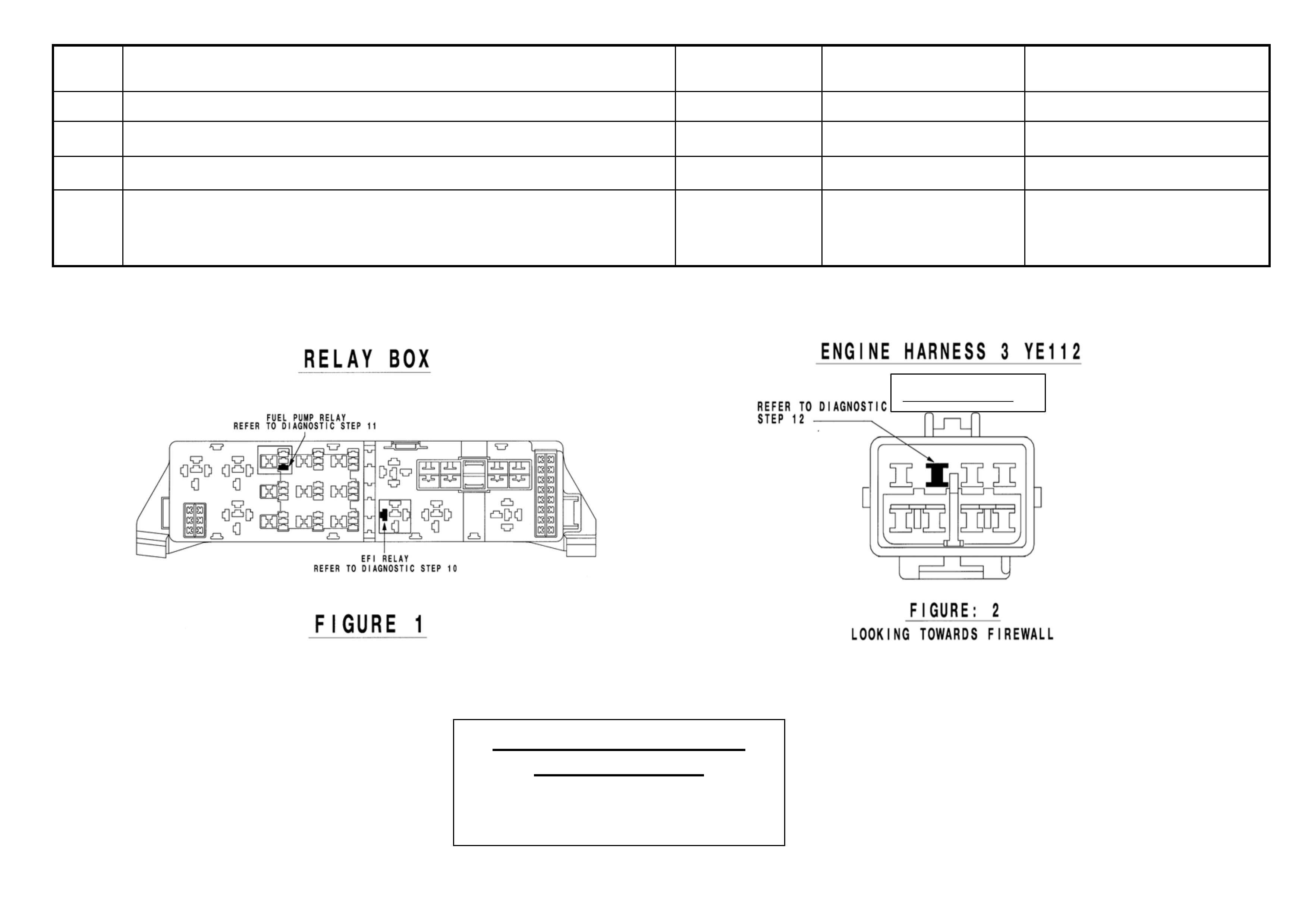
5 • Remove the EFI relay and back probe terminal 85 (as per figure 1 for VT.II / WH Vehicles or as per figure 3 for
VY / WK/ VZ Vehicles), with reference to Ground.
• With the Ignition switch to ON, measure DC voltage.
_____________ volts DC.
6 • Remove Fuel Pump relay and back probe terminal 1 (as per figure 1 for VT.II / WH Vehicles) or terminal.2 (as
per figure 3 for VY / WK Vehicles) , to measure continuity with ref. to Ground.
• Turn the ignition to ON, measure resistance.
_____________ Ohms.
7 • For VY / WK Vehicles Disconnect Engine Connector (X206 located above passe nge r k i ck pa nel ) and back pr obe
pin 9 (as per figure 4) with reference to ground.
• For VT.II / WH Vehicles Di s c on nect En gi n e Connector (YE112) and ba ck probe pin (as per figure 2 ), wi t h
reference to Ground.
• For VZ vehicles Disconnect ECM connector A43 X1 and back probe pin 19 (as per figure 5) with reference to
ground.
• Turn the ignition to ON, measure DC voltage.
_____________ volts DC
8 • Is communications with Tech 2 active?
9 • With TDL flashing, operate “Unlock” button on the Remote Control.
• Does the TDL stop flashing?
Dealer Code: ISOVIN: Vehicle Build Date:
Km’s: ESS Pin No: BCM Part No: BCM Barcode No: .
This check sheet must signed by the Service Manager. ____________________________ Date: ____________
Fax the completed copy to Australian Arrow Customer Service. Facsimile: (03) 9775 0954.

HSV – EMBEDDED SECURITY SYSTEM (ESS) DIAGNOSTIC PROCEDURE (VT.II / WH / VY / WK / VZ).
STEP ACTION VALUE
YES NO
1 • Turn ignition to ON position.
• Is one (1) beep audible? • Go to Step 2 • Go to Step 3.
2 • Turn Ignition switch to the Start position.
• Does the vehicle start? • System O.K, return
vehicle to
customer.
• Go to Step 11.
3 • Are five (5) beeps audible? • Go to Step 13. • Go to Step 8.
4 • Turn Ignition switch to the Start position.
• Does the vehicle start? • Go to Step 5. • Go to Step 6.
5 • Fill in the ESS check sheet and Contact Australian Arrow
Customer Service.
6 • Has there been a BCM replacement? • Go to Step 5. • Go to Step 14.
7 • Perform Serial Data Communications diagnostic as per Holden
Service Manual, then go to Step 5.
8 • Zero beeps were audible? • Go to Step 9. • Record number of beeps,
then go to Step 5.
9 • Turn Ignition switch to the Start position.
• Does the vehicle start? • Go to Step 5. • Go to Step 10.
10 • Remove the EFI relay and back probe terminal 85 (as per figure.1
for VT.II / WH vehicle), or (as per figure.3 for VY/WK/VZ
vehicle), with reference to Ground.
• With the Ignition switch to ON, Is the value as specified?
• 12 volts DC. • Go to Step 5. • Refer to Service Manual
and check Ignition
system.
11 • Remove Fuel Pump relay and back probe terminal.1 (as per figure.1
for VT.II / WH vehicle), or (as per figure.3 terminal.2 for
VY/WK/VZ vehicle), to check continuity with reference to
Ground.
• Turn the ignition to ON. Is the value as specified?
• Less than
one (1) Ohm.
• Go to Step 12. • Go to Step 5.
12 • For VT.II / WH vehicle, Disconnect Engine Connector (YE112)
and back probe pin (as per figure 2), with reference to Ground.
• For VY/WK vehicle, Disconnect Engine Connector (X206 located
above passenger kick panel), and back probe pin.9 (as per figure.4),
with reference to ground.
• For VZ vehicles Disconnect ECM connector A43 X1 and back
• 12 volts DC • Go to Step 5. • Go to Step 5.
probe terminal 19 (as per figure 5) with reference to ground.
• Turn the ignition to ON. Is the value as specified?
STEP ACTION VALUE YES NO
13 • Is the Theft Deterrent Led flashing? • Go to Step 4. • Go to Step 5.
14 • Is communications with Tech 2 active? • Go to Step 15. • Go to Step 7.
15 • With TDL flashing, operate “Unlock” button on the Remote Key.
• Does the TDL stop flashing? • Go to Step 5. • Refer to Theft Deterrent
System diagnostics in
Holden Service Manual.
(Grey C onn ector)
Australian Arrow Pty. Ltd.
Customer Service.
Telephone: (03) 9785 0792
Facsimile: (03) 9775 0954
Electri cal and Instruments Page I-14
Page I-14
4 Electro-Chromatic Mirrors
4.1 General Information
Electro-chromatic mirrors are standard fitment in all New Zealand WK Grange vehicles. The mirror features an electronically
controlled mirror cell which changes colour in response to an applied electrical voltage. This allows automatic darkening of
the mirror during night driving when the headlamps of a following vehicle shine on an integrated light sensor. This function
only operates when the integral sensor detects low ambient (i.e. at night time). The mirror operates automatically, however,
an AUTO/MANUAL switch provides the driver with the option for the mirror to be darkened during low ambient light
conditions regardless of presence or absence of following headlamps. When reverse gear is selected, the mirror
automatically lightens.
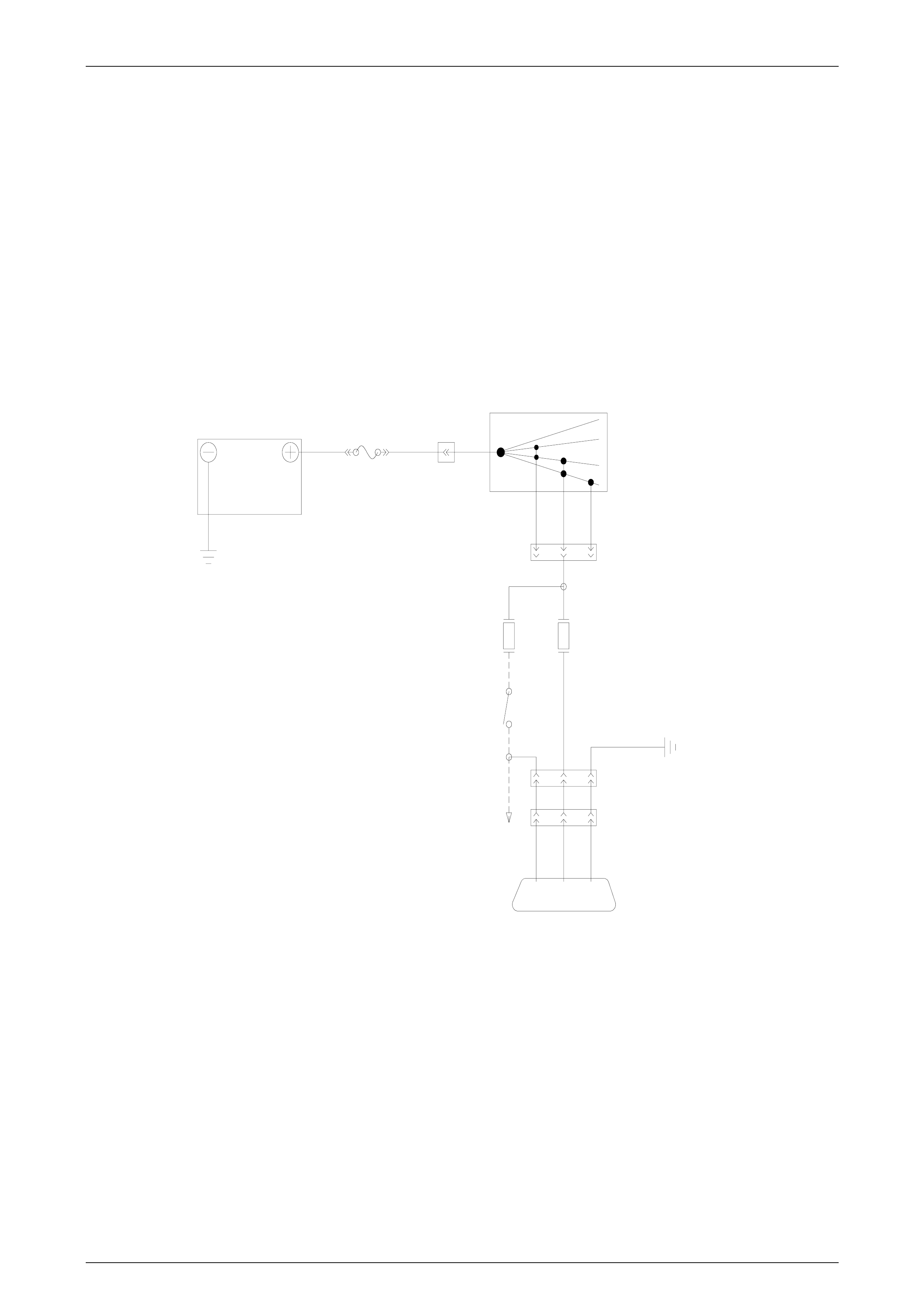
Circuit Details
FJ RYB44
OFF
ACC
IGN
START
IG NIT ION SWITCH
YB44
P
F15F12
BACK-UP
SWITCH
YB185
YB113
BR/BLU
LG
P
B/BLU
ELECTRO-CHROMATIC MIRROR
BATTERY

Electri cal and Instruments Page I-15
Page I-15
5 HSV Fog Lamps
5.1 General Information
HSV Fog/cornering lamps are fitted directly to the front fascia of all HSV WK Grange models. The HSV lamps use a
glass convex reflector to provide a wide-angle beam concentrated in a range of 30 to 40 metres in front of the lamp. The
external lens incorporates a clear horizontal section.
• Fog lamps should be only used in adverse weather condition, i.e. fog.
• Use of fog lamps on hot sunny days may result in failure from overheating.
• Fog lamps are not daylight running lights.

Electri cal and Instruments Page I-16
Page I-16
5.2 Service Operation
Refer to Sect ion 12B Light ing Sy stem, of the Holden WK Service Information.
12C-031301 LAMP FOG/CORNERING LH
12C-031302 LAMP FOG/CORNERING RH
NOTE
Condensation may appear on the lense of the fog
lamp when appropriate ambient conditions exist.
This condensation will clear as the ambient
conditions change or after four or five minutes
operation of the fog lamps