
SECTION 0C - DIAGNOSTICS
General Information
Programming Tech 2
General Information
Standard Update
Custom Update
Using Tech 2 On The Vehicle
Connecting Tech 2 To The Vehicle
Powertrain Application Menu
3.0L L4 4JH1TC Engine Tech 2 Functions
3.2L V6 6VDE1 Engine Tech 2 Functions
Transmission Application Menu
AW30-40LE Transmission Tech 2 Functions
THM 4L30E Transmission Tech 2 Functions
Chassis Application Menu - ABS
ABS Tech 2 Functions
Chassis Application Menu - TOD
Torque On Demand Tech 2 Functions
Body Application Menu - Immobiliser
Immobiliser Tech 2 Functions
Body Application Menu - SRS
SRS Tech 2 Functions
General Information
The Tech 2 is a hand-held diagnostic computer which has been designed specifically to help Dealership Technicians
diagnose and repair the electronic systems used on Holden vehicles.
NOTE: Due to the constant evolution of TECH 2 software, the screens shown in this section may differ slightly
from those displayed for the vehicle being tested.
Programming Tech 2
General Information
Before Tech 2 can be used on a vehicle it will have to be
programmed with the latest software. Tech 2
programming is used to update Tech 2. TIS 2000
contains the current Tech 2 applications (program) and
one preceding version. Tech 2 can be programmed
using the following procedure.
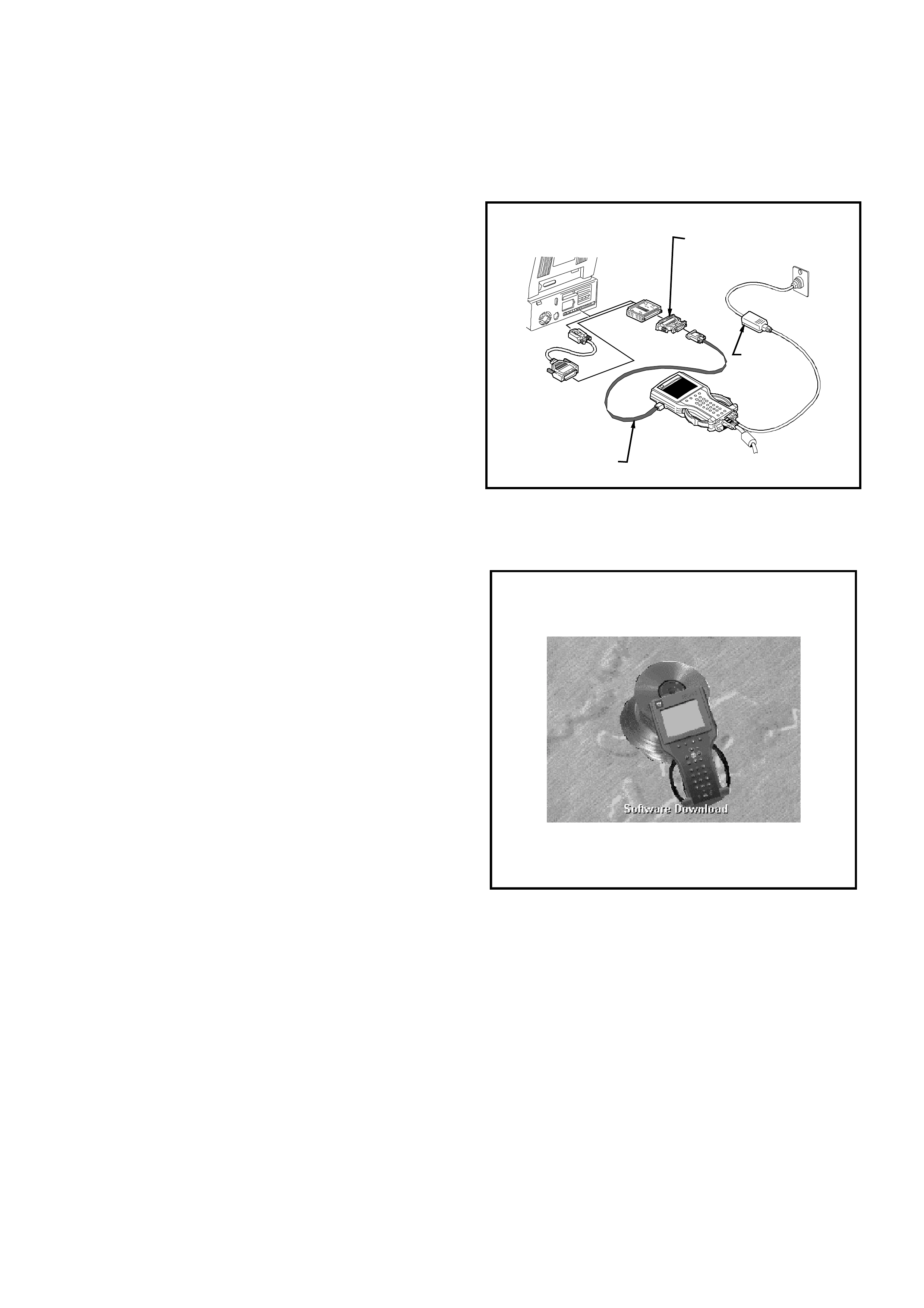
1. Connect the RS-232 (1) cable to the Tech 2 RS-232
communication port.
2. Connect the other end of the RS-232 cable to the
DB-9 adapter and then connect the DB-9 adapter to
the serial communication port of your computer.
NOTE: If your computer has a 25 pin serial
communication port you will need to fit the 25/9 pin
adapter between the nine pin DB-9 adapter and the
serial communication port.
3. Connect the AC power supply to the Tech 2 power
jack.
4. Press the PWR button to turn on Tech 2.
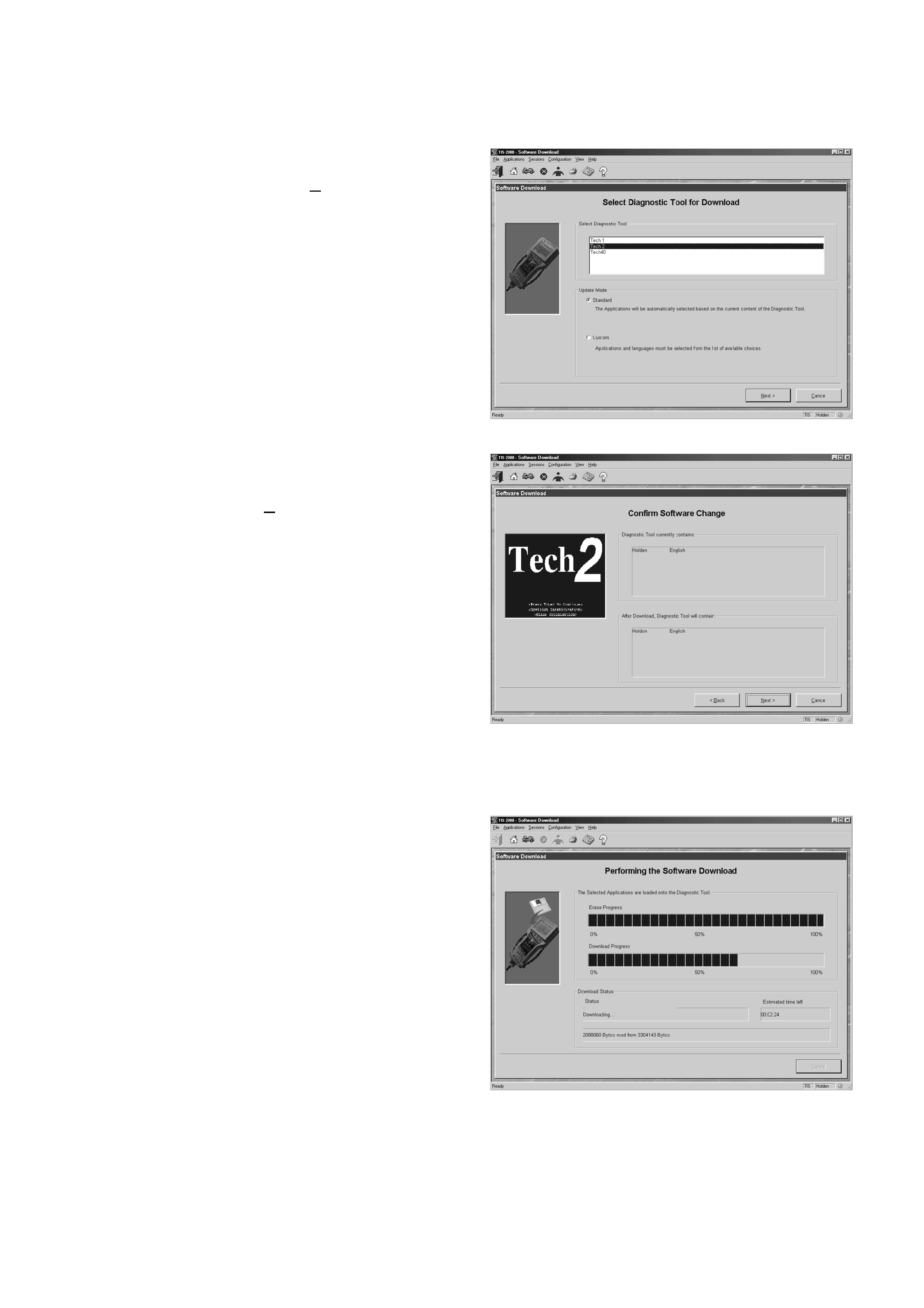
5. From the TIS 2000 Main Menu, click on the
Software Download icon.
There are two download modes: Standard and Custom.
Standard installs the latest software version of the
currently programmed language and make onto the
Tech 2.
Custom allows you to perform backdating, install
different make software or alternate languages onto the
Tech 2.
Standard Update
The procedure for performing a standard Tech 2 update
using the TIS 2000 Software Download is as follows:
1. Connect the Tech 2 to the PC using the RS-232
cable, DB-9 adapter and the 25/9 pin adapter if
required.
2. Power up the Tech 2 using the AC power supply
that comes standard with the Tech 2 kit.
Tech 2 must be at the Title Screen.
2
3
TECH
2
1
UBS2001b
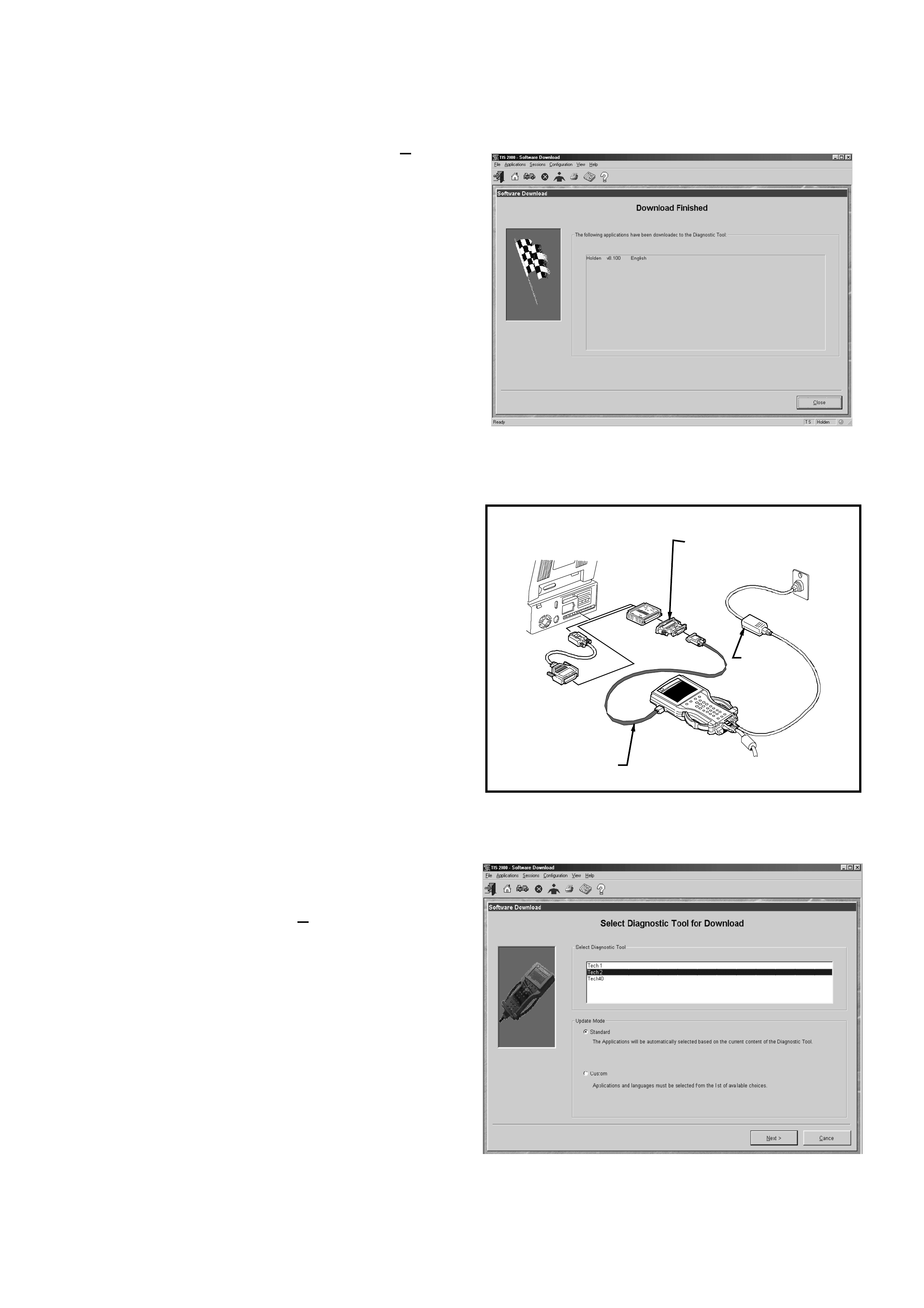
3. At the TIS 2000 Select Diagnostic Tool for
Download screen highlight your selection (TECH
2) and select the Standard update mode.
After making your selections, click Next>. A message
will appear indicating the PC is reading the contents of
the diagnostic tool.
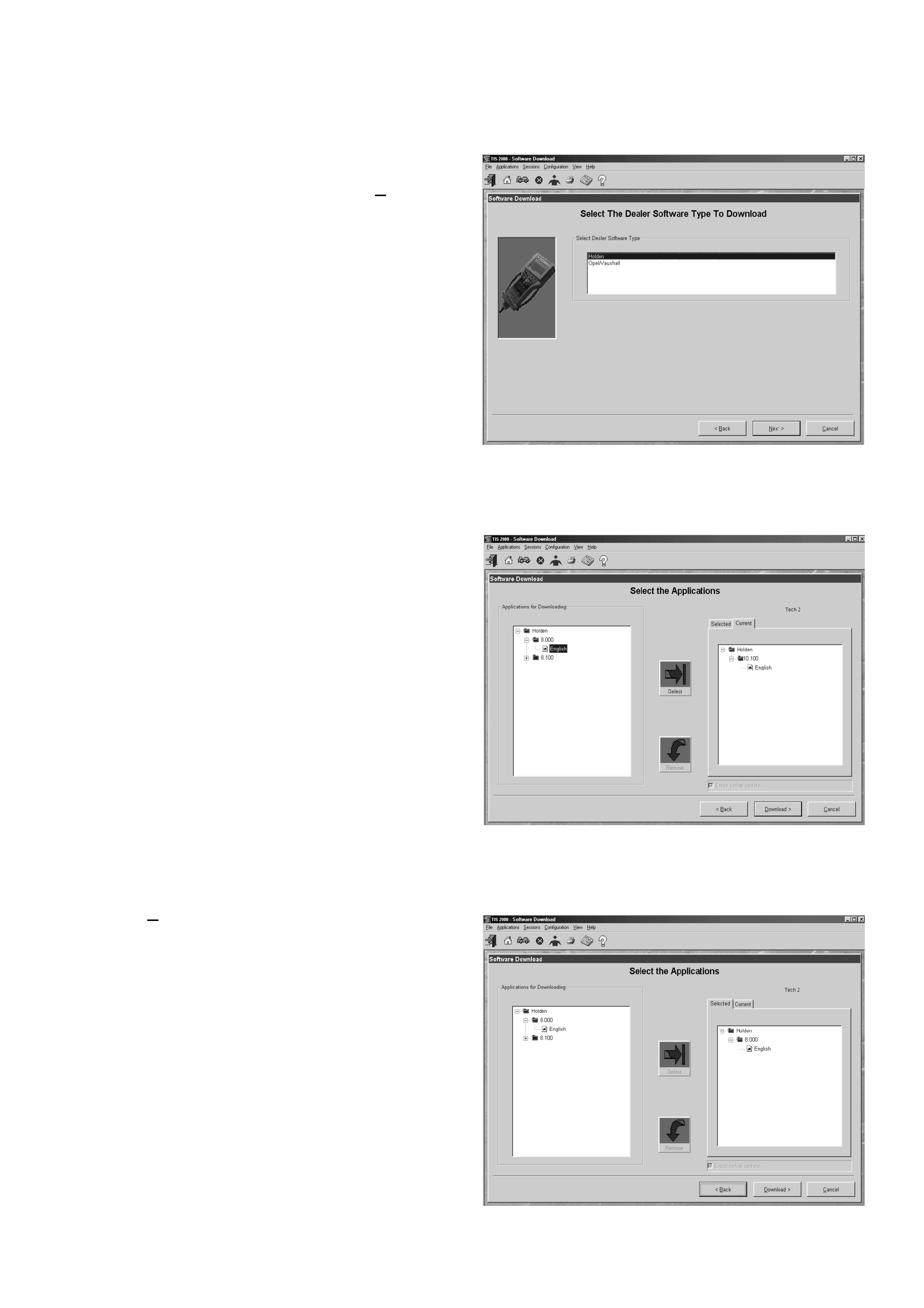
4. The PC will display a Confirm Software Change
screen showing what software version the Tech 2
currently contains and what it will contain after the
software download. Click Next> to continue.
5. A Performing the Software Download screen will
appear. It tracks the status of the software
download.
6. When the software download is complete, a
Download Finished screen appears. Click on Close
to close the application. The scan tool now contains
the latest software.
Custom Update
A custom update is used to backdate the TECH 2,
install Non-Holden software or install different language
software. After selecting Custom as the update mode
from the selection screen, do the following:
1. Connect the TECH 2 to the PC using the RS-232
cable (1), DB-9 adapter and the 25/9 pin (2)adapter
if required.
2. Power up the Tech 2 using the AC power supply (3)
that comes standard with the TECH 2 kit.
Tech 2 must be at the Title Screen.
3. At the TIS 2000 Select Diagnostic Tool for
Download screen highlight your selection (TECH
2) and select the Custom update mode.
After making your selections, click Next>. A message
will appear indicating the PC is reading the contents of
the diagnostic tool.
2
3
TECH 2
1
UBS2001b
4. The Select The Dealer Software Type to
Download screen will then be displayed. Select the
desired software type and the click Next> to
continue.
5. A Select the Applications screen will appear. The
left side of the screen lists software release
numbers. Click on the “+” sign to see a list of
different languages for each release.
6. Select the desired software version and language
by either double-clicking or clicking the Select icon.
The selected software will appear in the right side of
the screen.
To compare the current and selected Tech 2 software,
click on the Current or Selected tabs on the right side
of the screen.
7. Click on Download> to begin the update.
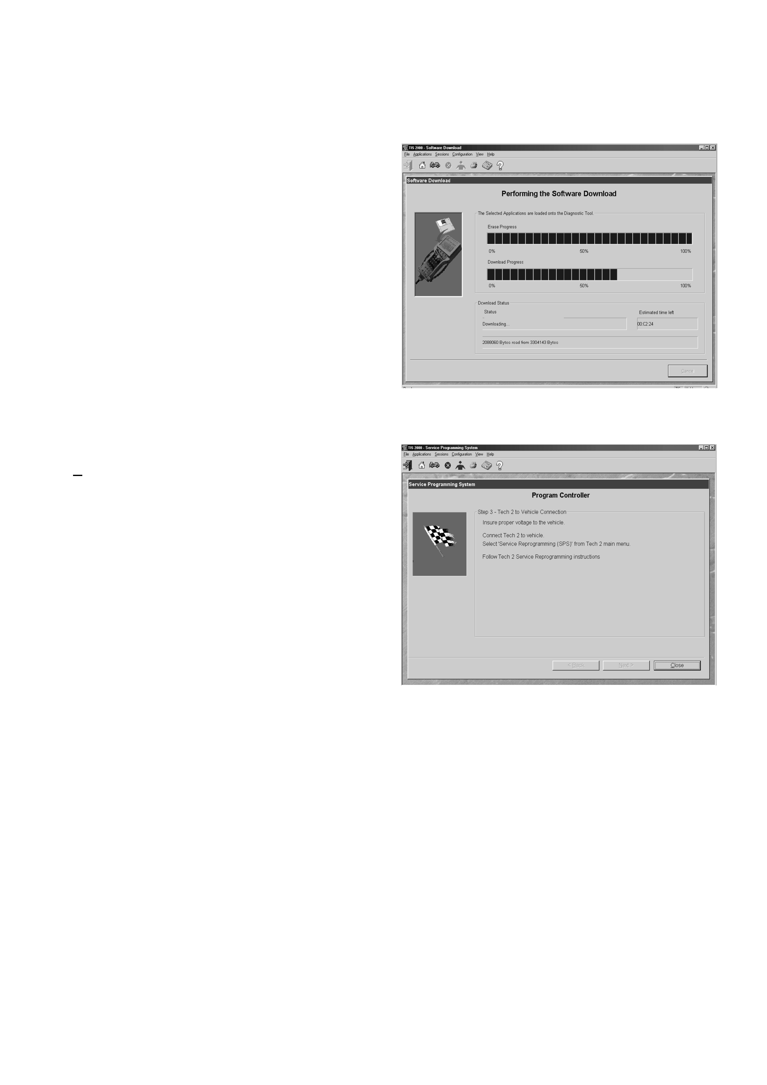
8. A Performing the Software Download screen will
appear. It tracks the status of the software
download.
9. When the software download is complete, a
Download Finished screen appears. Click on
Close to close the application. The TECH 2 now
contains the selected software.
Using Tech 2 On The Vehicle
NOTE: Due to the constant evolution of TECH 2
software, the screens shown in this section may
differ slightly from those displayed for the vehicle
being tested.
Connecting TECH 2 To The Vehicle
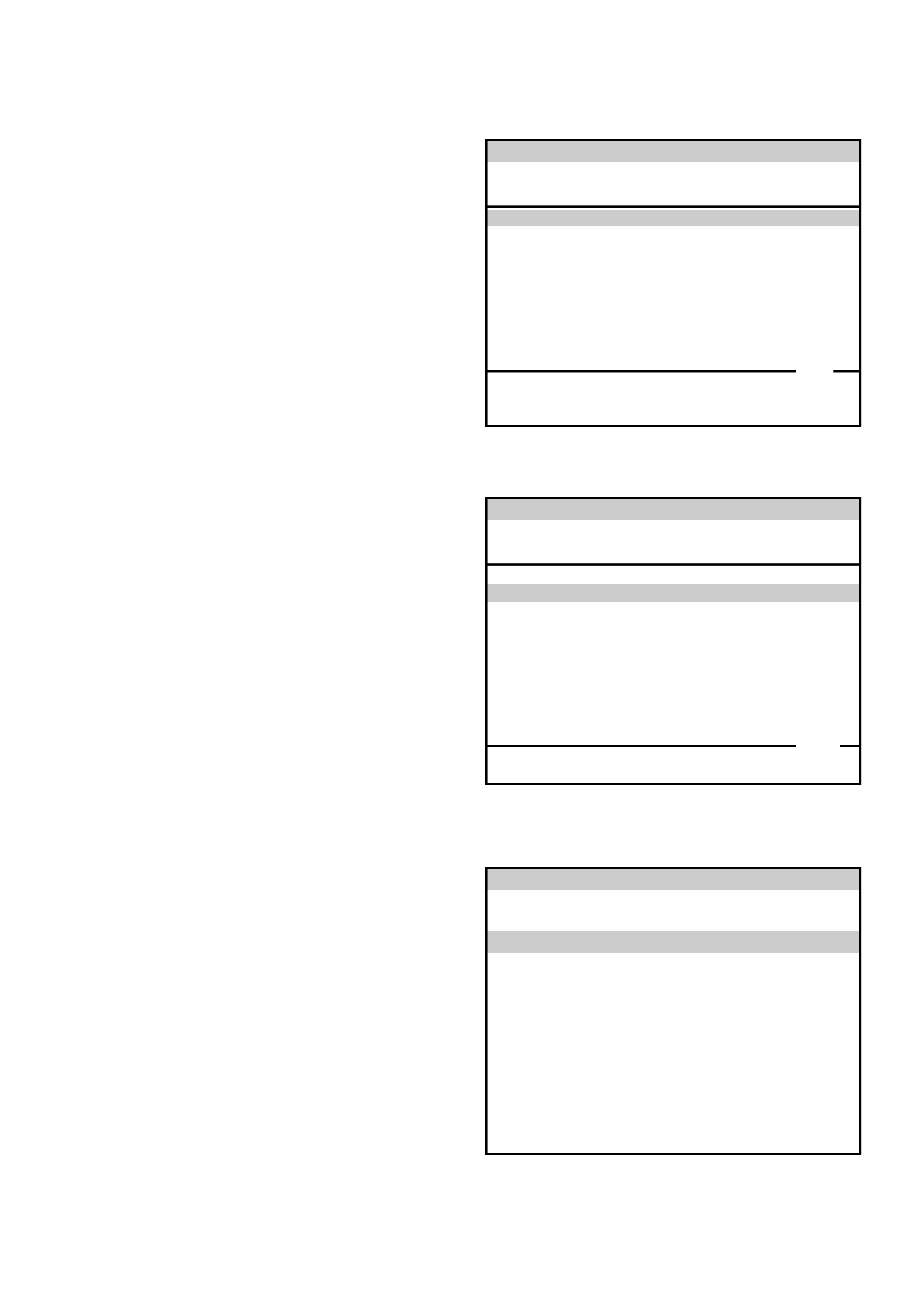
1. Connect Tech 2 to the vehicle DLC, with the DLC
cable and the 16/19 pin adapter.
2. Switch the unit on by pressing the power button (2).
A green light (1) should come on indicating that the
tool is receiving power.
NOTE: At this time the technician should see the Power
On Self Test (POST) run. The POST is a built in
diagnostic self test for the TECH 2 that should find most
common system faults. The POST is run on every
power up to ensure the best operation of the tool. After
the completion of the POST, the TECH 2 unit will briefly
show the POST results. If POST passes, the tool will
continue onto the title screen. If POST fails, results of all
tests will be displayed, and this should show which test
failed. POST failures may be classified as fatal or non-
fatal. A fatal error will not allow the user to continue
using the tool. Failure of the keypad would be an
example of a fatal error. Non-fatal errors found during
the POST will allow continued use of the TECH 2, but
with some limitations. If either a fatal or non-fatal error
occurs, refer to the Troubleshooting section of the
TECH 2 User's Guide.
1. Power Status Indicator Light
2. PWR (Power) Key
3. SHIFT Key
4. SHIFT Key Status Indicator Light
3. At the Tech 2 title screen press the ENTER key to
continue.
PWR
F0
F3
F6
F9
F1
F4
F7
F2
F5
F8
?
GM
TECH 2
2
2
Tech
10 Megabyte
Press [ENTER] to continue
Software Version 11.010
Holden 1997 - 2002
2
1
4
3

4. A selection can be made from the Main Menu,
either by using a function key or by using the arrow
keys to highlight a menu choice and pressing
ENTER.
•NOTE: You will then need to supply some additional
information to the TECH 2. This requires navigation
through a series of lists (called picklists). On some
menus or picklists, the user can use a function key to
make a menu selection, but most of the picklists
require using the selection and action keys. If a
mistake is made in the selection process, or if a
different application or function is desired, press EXIT
to back up one level. Within an application, there may
be soft keys which are available for use. These soft
keys allow access to additional tool functions without
exiting a current tool function. Soft keys are made up
of sets which will appear together. To see the next set
of soft keys, select the More soft key.
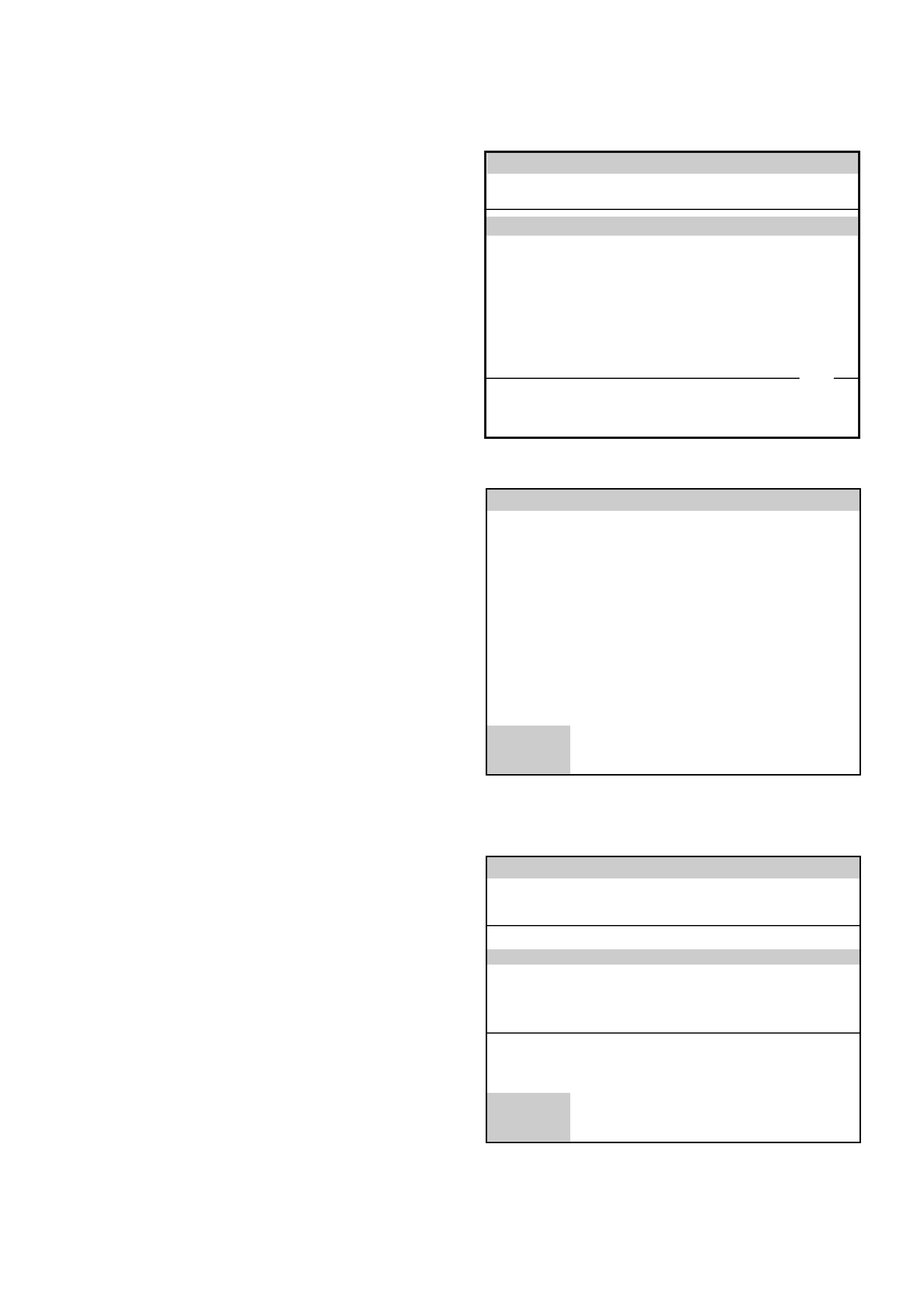
The TECH 2 Main Menu contains the following:
F0: Diagnostics
Contains all functions to test, diagnose, monitor and
program the different vehicle systems.
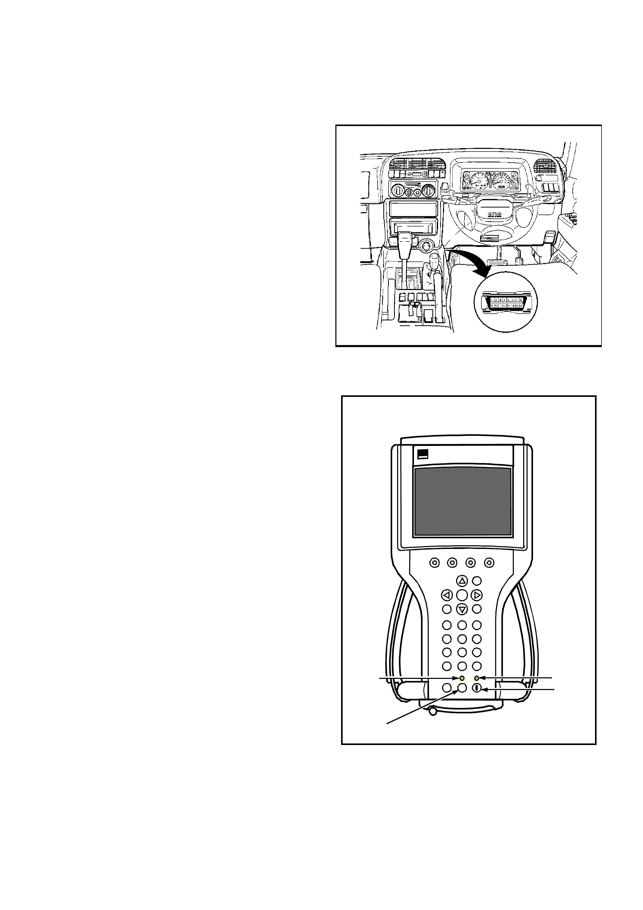
F1: Service Programming System (SPS)
SPS is used in conjunction with Technical
Information System (TIS) 2000 to program vehicle
control units.
F2: View Capture Data
Contains all functions to work with one or two
previously recorded snapshots on one or two
vehicles. This function is to enable the viewing of
captured data without a vehicle.
F3: Tool Options
Contains the TECH 2 self test, set clock, set units,
set screen contrast and Getting Started.
F4: Download/Upload Help
Contains help information on the downloading and
uploading from the TECH 2 to the TIS 2000 CD-
ROM.
Main Menu
UBS2000a
F0: Diagnostics
F1: Service Programming System (SPS)
F2: View Capture Data
F3: Tool Options
F4: Download/Upload Help
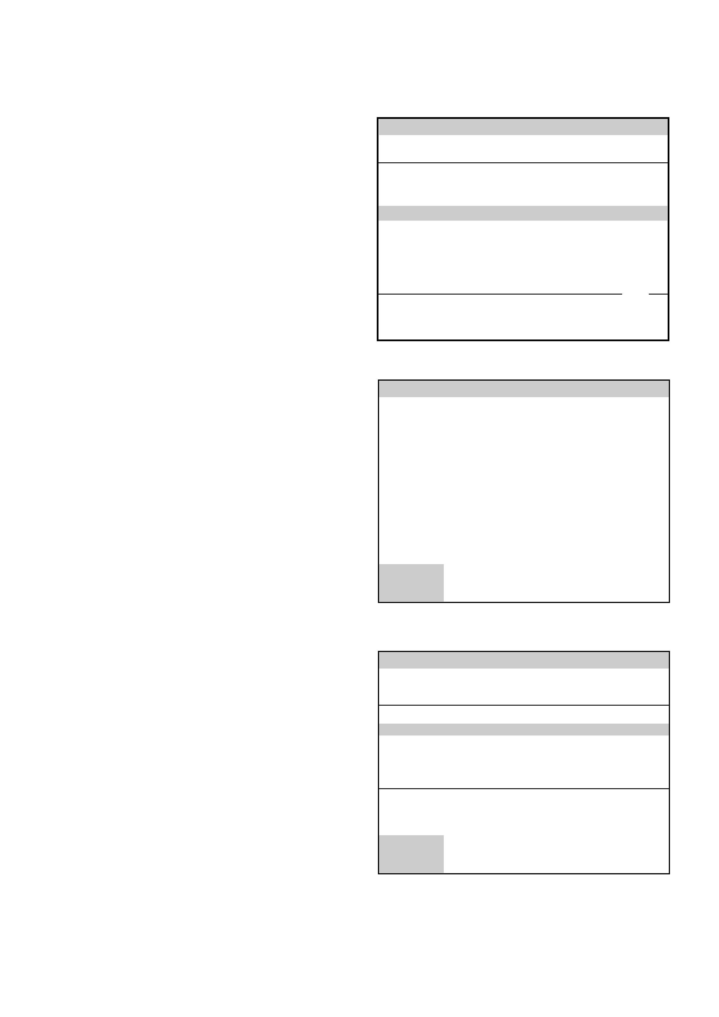
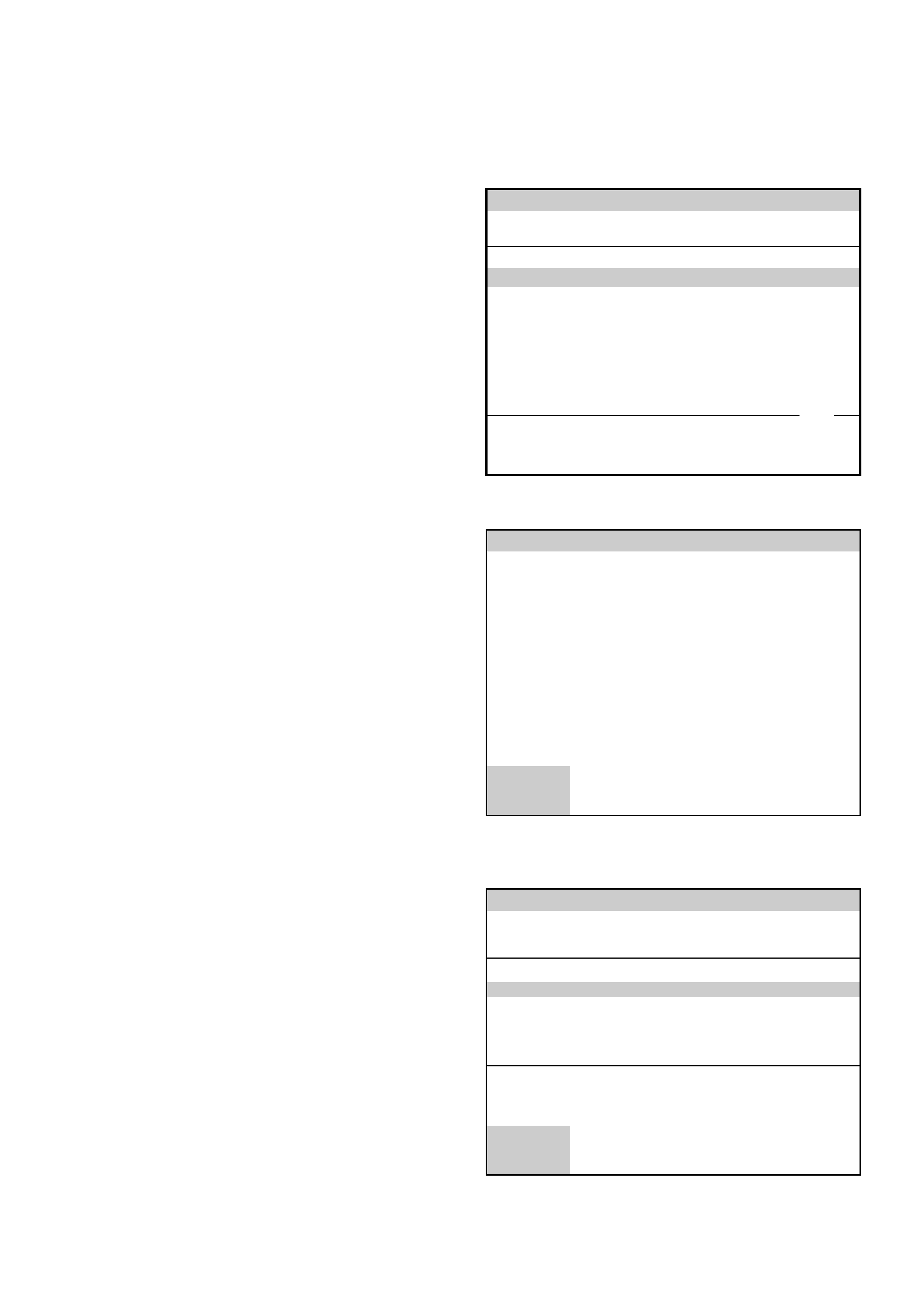
5. Select the correct Model Year with the arrow keys
and the press ENTER. The Vehicle identification
screen will then be displayed.
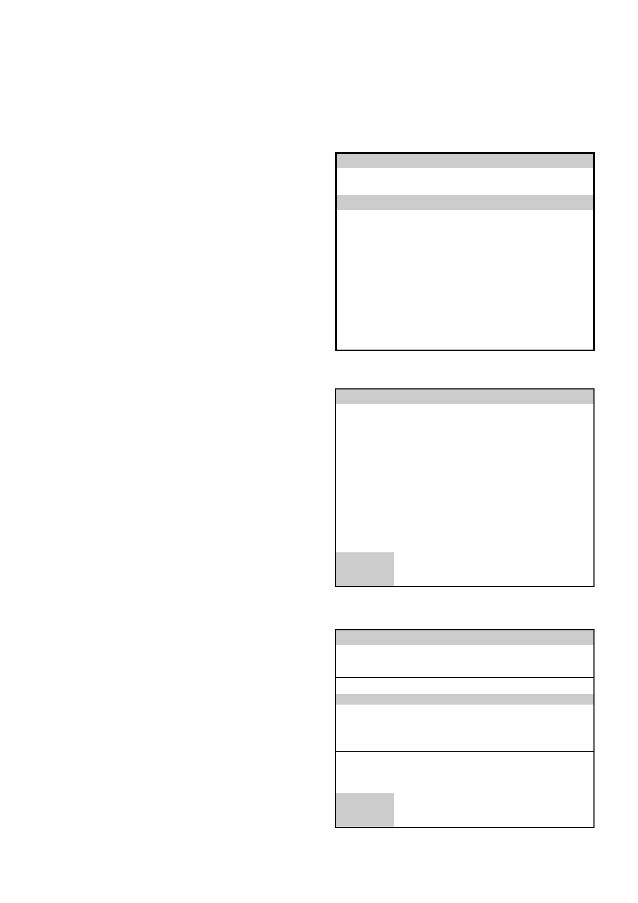
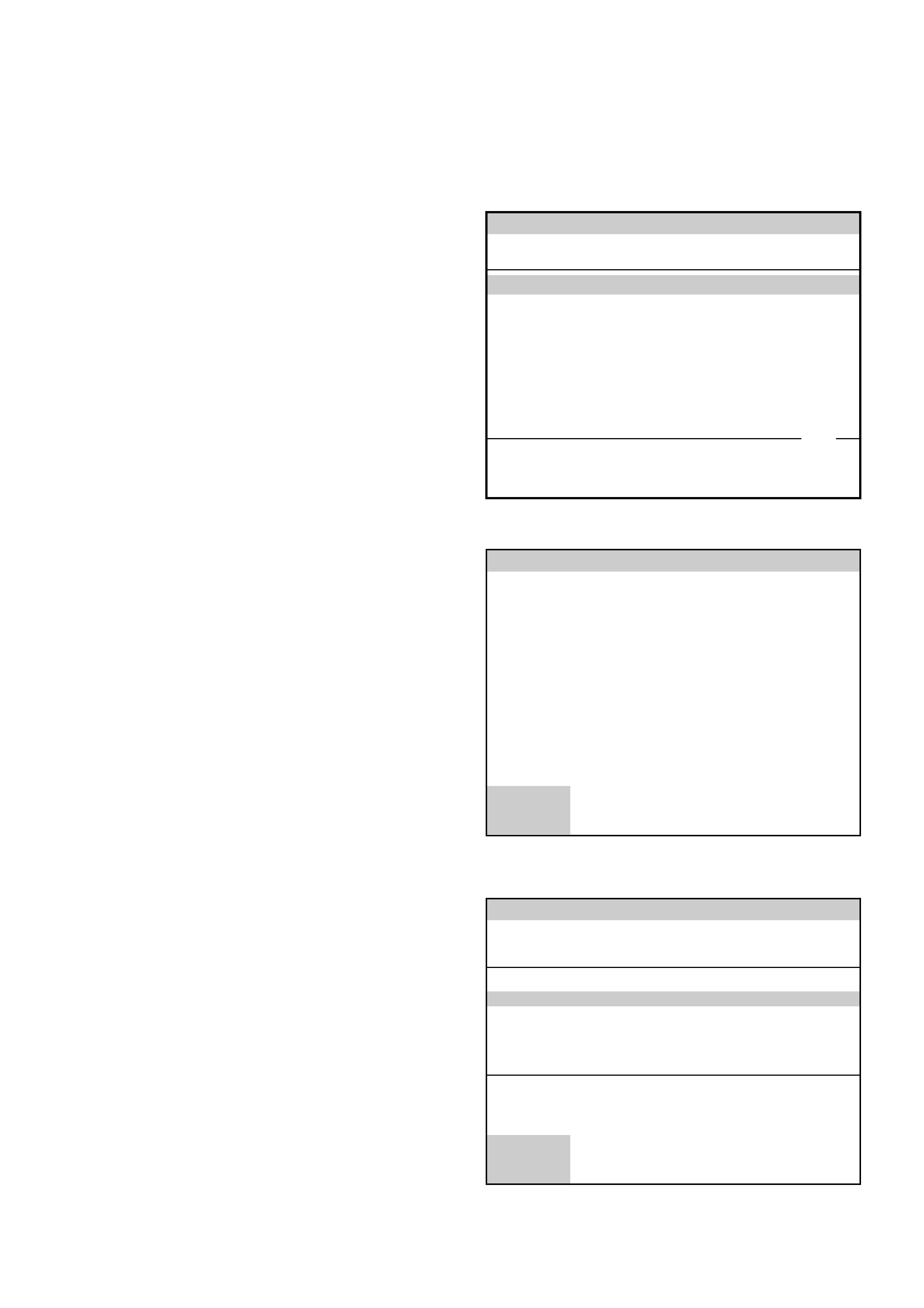
6. Select the correct Vehicle Type with the arrow keys
and the press ENTER. The System Select Menu
will then be displayed.
7. The desired system can be selected from the
System Select Menu with the function keys or with
arrow keys and then press ENTER.
F0:Powertrain contains all functions to test,
diagnose, and monitor the engine and transmission
systems that communicate with the Tech 2 via the
Powertrain Control Module (PCM).
F1: Chassis contains all functions to test,
diagnose, monitor the vehicles chassis systems;
TOD and ABS modules.
F2: Body contains all functions to test, diagnose,
monitor the instruments and Supplemental
Restraint System.
Main Menu
Select one of the following
Model Year(s)
UBS2001a
(2)
(1)
(Y)
(X)
(W)
(2)
2002
2001
2000
1999
1998
1 / 5
2002
Main Menu
Select one of the following
Vehicle Type(s)
Frontera
Jackaroo
Rodeo
VX Commodore
VU Utility
WH Statesman & Caprice
Corsa-B
Corsa-C
Astra-F
Astra-G
Jackaroo
2 / 10
UBS2001
System Select Menu
(2) 2002 Jackaroo
F0: Powertrain
F1: Chassis
F2: Body
UBS2002
Powertrain Application Menu
1. Select the correct engine from the Vehicle
Identification menu with the arrow keys, then
press ENTER.
2. Turn on the ignition and press the Confirm soft key.
3. The Engine identification screen will then display
the PCM identification information, which will vary
depending upon engine type and software level.
Press the Confirm soft key, the engine application
menu will then be displayed.
NOTE: If Tech 2 is able to communicate with the
PCM the Engine identification information will be
displayed. If Tech 2 is unable to communicate with
the PCM, Tech 2 will display “Waiting for Data”.
The following functions can be selected from the
engine application menu:
F0: Diagnostic Trouble Codes
F1: Data Display
F2: Snapshot
F3: Miscellaneous Tests
F4: Programming
Vehicle Identification
Select one of the following
Powertrain
3.0L L4 4JX1
3.5L V6 6VE1
4L30E
AW30-40LE
3.0L L4 4JX1
1 / 4
UBS2004
Powertrain
(2) 2002 Jackaroo
Electronic System: 3.0L L4 4JX1
Turn Ignition On!
UBS2004h
Confirm
Powertrain
(2) 2002 Jackaroo
Electronic System: 3.0L L4 4JX1
Part Number
Broadcast Code
Identifier
9383459
DJWD
40C
Part Number
UBS2004j
Confirm

3.0L L4 4JX1TC Engine Functions
F0: Diagnostic Trouble Codes
In this test mode, DTCs stored by the ECU can be displayed or cleared. When F0: Diagnostic Trouble Codes is
selected, there are an additional three modes:
F0: Read DTC Information By Priority: All current DTC(s) will be displayed.
F1: Read DTC Information As Stored By ECU: All current DTC(s) will be displayed.
F2: Clear DTC Information: Clears all current DTC(s) in the ECM memory.
F3: Freeze Frame/Failure Records: Freeze Frame is an element of the Diagnostic Management Ssytem which
stores various items of vehicle information at the moment an emissions related DTC is logged in memory and
the MIL is commanded ON.
Failure Records data is an enhancement of Freeze Frame. Failure Records store the same vehicle information
as Freeze Frame, but will store the information when DTC is logged in memory.
F1: Data Display
In this test mode, the TECH 2 continuously monitors and displays all engine data parameters.
F2: Snapshot
In this mode, the TECH 2 scan tool captures data before and after a selected snapshot triggering condition which may
or may not set a DTC.
F3: Miscellaneous Tests
In this test mode, the Tech 2 performs software override commands of the ECM, to assist in problem isolation during
diagnostics relating to the ECM’s output actuators.
F0: Glow Time Lamp: Allows the user to turn the ‘Glow Time’ Lamp ON & OFF.
F1: Exhaust Switching Valve 1: Allows the user to operate Exhaust Switching Valve #1.
F2: Exhaust Switching Valve 2: This test allows the user to operate Exhaust Switching Valve #2.
F3: Throttle Motor Control:This item allows the operator to monitor the effect of varying the position of the throttle
butterfly on engine operation.
F4: EGR Switching Valve: Allows the user to operate the EGR Switching valve.
F5: EGR Regulating Valve Control: This test simulates the commands from the ECM to the EGR Valve.. It allows
the operator to check the basic operation of the EGR system.
F6: Rail Pressure Control Valve: This test is conducted to verify the correct operation of the Rail pressure Control
Valve
F7: Injector Balance Test: This test simulates the commands from the ECM to the injectors when the engine is
idling. It allows the operator to check the basic operating efficiency of each injector/cylinder.
F8: Injector Control: In this test the ECM pulses the selected injector 1x per second, allowing audible confirmation
of injector solenoid operation.
NOTE: Many of the above test procedures require the engine coolant temperature to be a minimum of 85°C.
F4: Programming
F0: Read/Store Trim Data: Allows the operator to read and/or store the Injector Trim Data in the ECM
F1: Program: Allows the flow rate of each injector to be programmed into the ECM

3.2L V6 6VE1 Engine Functions
F0: Diagnostic Trouble Codes
In this test mode, DTCs stored by the PCM can be displayed or cleared. When F0: Diagnostic Trouble Codes is
selected, there are an additional four modes:
F0: Read Current DTC: All current DTC(s) will be displayed.
F1: Clear Current DTC: Clears all current DTC(s) in the PCM memory.
F2: DTC Information: All current DTC(s) will be displayed in numerical order.
F3: Freeze Frame/Failure Records: Freeze Frame is an element of the Diagnostic Management Ssytem which
stores various items of vehicle information at the moment an emissions related DTC is logged in memory and
the MIL is commanded ON.
Failure Records data is an enhancement of Freeze Frame. Failure Records store the same vehicle information
as Freeze Frame, but will store the information when DTC is logged in memory.
F1: Data Display
This mode displays data parameters for the system being diagnosed. When entering this mode, there are three
modes:
F0: Engine Data: In this test mode, the TECH 2 continuously monitors and displays all engine data parameters.
F1: Misfire Data: In this test mode, the TECH 2 continuously monitors the PCM’s “mis-fire counters”. A current and
history misfire counter are maintained for each cylinder. Engine data parameters relevant to the misfire are
displayed along with the misfire counters.
F2: O2 Sensor Data: The Tech 2 continuously monitors and displays engine data parameters.
F2:Snapshot
In this mode, the TECH 2 scan tool captures data before and after a selected snapshot triggering condition which may
or may not set a DTC.
F3:Miscellaneous Tests
In this test mode, the Tech 2 performs software override commands of the PCM, to assist in problem isolation during
diagnostics.
F0: Lamps: The MIL (Malfunction Indicator Lamp) can be commanded on and off.
F1: Relays: The A/C Compressor Clutch relay and the Fuel Pump relay can be commanded on and off.
F2: EVAP: The Cannister Purge Solenoid operation can be commanded between 0% and 99%.
F3: Fuel System: Fuel Trim can be enabled or reset and O2 loop status monitored.
F4: Instruments: Tachometer Control allows the basic operation of the tachometer to be tested.
F5: EGR Control: The EGR Valve operation can be commanded between 0% and 99% in 10% increments.
F6: Variable Intake Manifold Solenoid: Used to command the Variable Intake Manifold Solenoid ON and OFF.
F7:Injector Balance Test: Allows individual injectors to be disabled and the resultant drop in engine RPM to be
monitored.
F4:System Information
In this mode, the TECH 2 displays the status of the Malfunction Indicator Lamp (MIL) and the number of emission
related DTC’s set.
Transmission Application Menu
1. Select the correct transmission from the Vehicle
Identification menu with the arrow keys, then press
ENTER and follow the screen instructions.
2. Turn on the ignition and press the Confirm soft key.
3. The Transmission Identification screen will then
display the Part Number and Identifier. This
information will vary with engine type and software
level. Press the Confirm soft key, the transmission
application menu will then be displayed.
NOTE: If Tech 2 is able to communicate with the
PCM the Engine identification information will be
displayed. If Tech 2 is unable to communicate with
the PCM, Tech 2 will display “Waiting for Data”.
The following functions are available in the
transmission application menu:
F0: Diagnostic Trouble Codes
F1: Data Display
F2: Snapshot
F3: Miscellaneous Tests
F4: Function Tests
Vehicle Identification
Select one of the following
Powertrain
3.0L L4 4JX1
3.5L V6 6VE1
4L30E
AW30-40LE
AW30-40LE
4 / 4
UBS2006
Powertrain
(2) 2002 Jackaroo
Electronic System: AW30-40LE
Turn Ignition On!
UBS2006k
Confirm
Powertrain
(2) 2002 Jackaroo
Electronic System: AW30-40LE
Part Number
Identifier
97230821
801
Part Number
UBS2006m
Confirm

AW30-40LE Transmission Functions
F0: DIAGNOSTIC TROUBLE CODES
In this test mode, DTCs stored by the TCM can be displayed or cleared. When F0: Diagnostic Trouble Codes is
selected, there are three additional modes:
F0: Read DTC Info As Stored: All current DTC(s) will be displayed in the they were order stored in memory.
F1: Clear DTC Information: Clears all current DTC(s) in the PCM memory.
F2: DTC Information: When this item is selected, there are an additional two modes:
F0: History: This item indicates that the DTC has been stored in memory as a valid fault. Type B DTCs will not
be stored as history DTCs until after the test has failed two consecutive trips.
F1: Last Test Failed: This message indicates the last diagnostic test failed. If the DTC is a type B, this test will
have occurred in a previous ignition cycle. This message will remain until the test passes or the DTCs are
cleared. If the DTC is a type C or D, this message will clear when the ignition is cycled.
F1: DATA DISPLAY
In this mode, TECH 2 continuously monitors transmission data. When F1: Data Display is selected, there are
additional two modes:
F0: Transmission Data: TECH 2 continuously monitors transmission data.
F1: TCC Data: TECH 2 continuously monitors torque converter clutch data.
F2: SNAPSHOT
In this test mode, the TECH 2 scan tool captures data before and after a snapshot triggering condition which may or
may not set a DTC. When F2: Snapshot is selected, there are two additional modes:
F0: Transmission Data
F1: TCC Data
F3: MISCELLANEOUS TESTS
In this test mode, the TECH 2 performs software override commands of the TCM, to assist in problem isolation during
diagnostics. When F2: Miscellaneous Tests is selected, there are additional two modes:
F0:Lamps: When this item is selected, there are an additional two modes:
F0: Check Light Test: Allows the user to turn the ‘CHECK TRANS’ Lamp ON & OFF.
F1: A/T Oil Temp Lamp Test: Allows the user to turn the ‘A/T Oil Temperature’ Lamp ON & OFF.
F1: Solenoids:
F0: Solenoid 1-2/3-4 test: Allows the user to turn the 1-2/3-4 shift solenoid ON & OFF.
F1: Solenoid 2-3 test: Allows the user to turn the 2-3 shift solenoid ON & OFF.
F2: TCC Solenoid test: Allows the user to turn the TCC solenoid ON & OFF.
F3: Pressure Control Solenoid test : Allows the user to increase and decrease the current through the PCS.

THM 4L30E Transmission Functions
F0: DIAGNOSTIC TROUBLE CODES
In this test mode, DTCs stored by the TCM can be displayed or cleared. When F0: Diagnostic Trouble Codes is
selected, there are an additional two modes:
F0: Read DTC Info By Priority: All current DTC(s) will be displayed.
F1: Clear Current DTC: Clears all current DTC(s) in the PCM memory.
F1: DATA DISPLAY
In this mode, TECH 2 continuously monitors transmission data. When F1: Data Display is selected, there are
additional two modes:
F0: Transmission Data: TECH 2 continuously monitors transmission data.
F1: TCC Data: TECH 2 continuously monitors torque converter clutch data.
F2: SNAPSHOT
In this test mode, the TECH 2 scan tool captures data before and after a snapshot triggering condition which may or
may not set a DTC.
F3: MISCELLANEOUS TESTS
In this test mode, the TECH 2 performs software override commands of the TCM, to assist in problem isolation during
diagnostics.
F0:Check Light: Allows the user to turn the ‘CHECK TRANS’ Lamp ON & OFF.
F1:Power Lamp: Allows the user to turn the ‘Power’ Lamp ON & OFF.
F2: Solenoid 1-2/3-4 test: Allows the user to turn the 1-2/3-4 shift solenoid ON & OFF.
F3: Solenoid 2-3 test: Allows the user to turn the 2-3 shift solenoid ON & OFF.
F4: Band Apply Solenoid: This test allows the user to turn the Band Apply solenoid ON & OFF.
F5: TCC Solenoid: Allows the user to turn the TCC solenoid ON & OFF.
F6: Power Control Driver Test: Allows the user to all turn solenoids ON & OFF simultaneously.
F7: Pressure Reg.Solenoid test: Allows the user to turn the Pressure Regulator Solenoid ON & OFF.
F8: Pressure Reg. Solenoid: Allows the user to increase and decrease the current through the PRS.
Chassis Application Menu - Antilock
Braking System (Abs)
1. Select the correct chassis system from the Vehicle
Identification menu with the arrow keys, then
press ENTER and follow the instructions on the
screen.
2. Turn on the ignition and press the Confirm soft key.
3. The System identification screen will then display
the control module Part number and System type.
Press the Confirm soft key, and the ABS application
menu will then be displayed.
The following functions are available in the ABS chassis
application menu:
F0: Diagnostic Trouble Codes
F1: Data Display
F2: Snapshot
F3: Actuators
F4: Miscellaneous Tests
System Select Menu
(2) 2002 Jackaroo
F0: ABS
F1: TOD
UBS2007a
Chassis
(2) 2002 Jackaroo
Electronic System: ABS
Turn Ignition On!
UBS2007j
Confirm
Chassis
(2) 2002 Jackaroo
Electronic System: ABS
Part Number
System
972047910
ABS
Part Number
UBS2007k
Confirm

ABS Tech 2 Functions
F0: DIAGNOSTIC TROUBLE CODES
In this test mode, DTC(s) stored by the ABS Module can be displayed or cleared. When F0: Diagnostic Trouble Codes
is selected, there are an additional three modes:
F0: Read Current DTC: All current DTC(s) will be displayed.
F1: Clear Current DTC: Clears all current DTC(s) in the PCM memory.
F2: DTC Information: All current DTC(s) will be displayed in numerical order.
F1: DATA DISPLAY
This mode TECH 2 continuously monitors and displays all ABS data parameters.
F2: SNAPSHOT
In this test mode, the TECH 2 scan tool captures data before and after a snapshot triggering condition which may or
may not set a DTC.
F3: ACTUATOR TESTS
In this test mode, the TECH 2 performs functional testes on the ABS that will help identify correct operation. In Testing
and observing results in this mode can further identify operational errors.
The following tests can be performed:
Return Pump Relay Test.
Front Left Solenoid Valve Test
Front Right Solenoid Valve Test
Rear Left Solenoid Valve Test
Rear Right Solenoid Valve Test
F4: MISCELLANEOUS TESTS
F0: Brake Bleed: This test prompts the Technician while bleeding the brake system.
The test is divided into two parts; a Primary Brake Bleed - which is a manual bleed of each brake circuit, and a
Secondary Bleed - where the module activates the solenoid and pump motor to expel any air which may be trapped
in the modulator hydraulic circuit.
Chassis Application Menu
Torque On Demand (TOD)
1. Select the correct chassis system from the Vehicle
Identification menu with the arrow keys, then
press ENTER and follow the instructions on the
screen.
2. Turn on the ignition and press the Confirm soft key.
3. The System identification screen will then display
the control module Part number and System type.
Press the Confirm soft key, and the TOD application
menu will then be displayed.
The following functions are available in the TOD chassis
application menu:
F0: Diagnostic Trouble Codes
F1: Data Display
F2: Snapshot
Vehicle Identification
Select one of the following
Chassis
ABS
TOD
TOD
2 / 2
UBS2009
Chassis
(2) 2002 Jackaroo
Electronic System: TOD
Turn Ignition On!
UBS2009a
Confirm
Chassis
(2) 2002 Jackaroo
Electronic System: TOD
Part Number
Identifier
972047910
903
Part Number
UBS2009b
Confirm

TOD Tech 2 Functions
F0: DIAGNOSTIC TROUBLE CODES
In this test mode, DTC(s) stored by the TOD Module can be displayed or cleared. There are two modes:
F0: Read Current DTC: All current DTC(s) will be displayed.
F1: Clear Current DTC: Clears all current DTC(s) in the PCM memory.
F1: DATA DISPLAY
This mode TECH 2 continuously monitors and displays all TOD data parameters.
F2: SNAPSHOT
In this test mode, the TECH 2 scan tool captures data before and after a snapshot triggering condition which may or
may not set a DTC.
Body Application Menu
Immobiliser
1. Select the correct body system from the Vehicle
Identification menu with the arrow keys, then
press ENTER and follow the instructions on the
screen.
2. Turn on the ignition and press the Confirm soft key.
3. The System identification screen will then display
the control module Part number and System type.
Press the Confirm soft key, and the Immobiliser
application menu will then be displayed.
The following functions are available in the Immobiliser
application menu:
F0: Diagnostic Trouble Codes
F1: Data Display
F2: Snapshot
F3: Additional Functions
F4: Programming
Vehicle Identification
Select one of the following
Body
Immobiliser
Airbag
Anti Theft System
Immobiliser
UBS2011
1 / 3
Body
(2) 2002 Jackaroo
Electronic System: Immobiliser
Turn Ignition On!
UBS2011m
Confirm
Body
(2) 2002 Jackaroo
Electronic System: Immobiliser
Part Number 89716841212
Part Number
UBS2011n
Confirm

Immobiliser TECH 2 Functions
F0: DIAGNOSTIC TROUBLE CODES
In this test mode, DTC(s) stored by the ABS Module can be displayed or cleared. There are three additional modes:
F0:Read Current DTC: All current DTC(s) will be displayed.
F1:Clear Current DTC: Clears all current DTC(s) in the Immobiliser memory.
F2:DTC Information: All current DTC(s) will be displayed in numerical order.
F1: DATA DISPLAY
This mode TECH 2 continuously monitors and displays all Immobiliser data parameters.
F2: SNAPSHOT
In this test mode, the TECH2 scan tool captures data before and after a snapshot triggering condition which may or
may not set a DTC. The Snapshot mode will help identify problems that may cause intermittent operation of the
Immobiliser system.
F3: Additional Functions
In this test mode, additional operations may be carried out on the Immobiliser system.
The folowing operations can be performed:
F0:Read ECU Identification
F1:Reset Immobiliser
F2: Erase Transponder Keys
F4: Programming
This mode allows the programming of replacement or additional components to the Immobiliser system.
F0:Program Immobiliser Function
F1:Program Transponder Keys
F2: Program Mechanical key Number
Note: Programming Approval must be obtained from TIS - Refer to Section 11A or Section 11B for
a complete explanation of the Immobiliser Programming sequence..
.
Body Application Menu
Airbag (Srs)
1. Select the correct body system from the Vehicle
Identification menu with the arrow keys, then
press ENTER and follow the instructions on the
screen.
2. Turn on the ignition and press the Confirm soft key.
3. The System identification screen will then display
the SRS Platform Identifier and Squib Circuit Code
Status.
Press the Confirm soft key, and the Airbag application
menu will then be displayed.
The following functions are available in the Airbag
application menu:
F0: Diagnostic Trouble Codes
F1: Data Display
F2: Snapshot
Vehicle Identification
Select one of the following
Body
Immobiliser
Airbag
Anti Theft System
Airbag
UBS2012
2 / 3
Body
(2) 2002 Jackaroo
Electronic System: Air Bag
Turn Ignition On!
UBS2012m
Confirm
System Identification
Confirm More
UBS2012c
(2) 2002 Jackaroo
Electronic System: Airbag
Platform Identifier: Trooper
Squib Circuit Code Stat.: Driver & Passenger

SRS TECH 2 Functions
F0: DIAGNOSTIC TROUBLE CODES
In this test mode, DTC(s) stored by the SRS Module can be displayed or cleared. There are two additional modes:
F0: Read Current DTC Information: All current DTC(s) will be displayed.
F1: Clear Current DTC Information: Clears all current DTC(s) in the memory.
F1: DATA DISPLAY
In this mode TECH 2 continuously monitors and displays all SRS Airbag System data parameters.
F2: SNAPSHOT
In this test mode, the TECH 2 scan tool captures data before and after a snapshot triggering condition which may or
may not set a DTC. The Snapshot mode will help identify problems that may cause intermittent operation of the SRS
system.