
SECTION 1A - BODY STRUCTURE
Service Precaution
Frame
General Description
Frame Dimensions (L W B)
General Description
Front Bumper
Parts Location
Removal
Installation
Front Bumper Slider Bracket
Removal
Installation
Rear Bumper
Parts Location
Removal
Installation
Parts Location (W/Rear Combination Light and
License Light)
Removal
Installation
Rear Bumper Slider
Removal
Installation
General Description
Cowl Cover
Parts Location
Removal
Installation
Engine Hood
Removal
Installation
Air Bulge
Parts Location
Removal
Installation
Engine Hood Hinge
Parts Location
Removal
Installation
Engine Hood Lock
Parts Location
Removal
Installation
Radiator Grille And Front End Lower Panel
Parts Location
Removal
Installation
Front Fender Panel
Parts Location
Removal
Installation
Body Mounting
Parts Location
Removal (No.1 – No. 2)
Removal (No. 3 — No. 6)
Installation
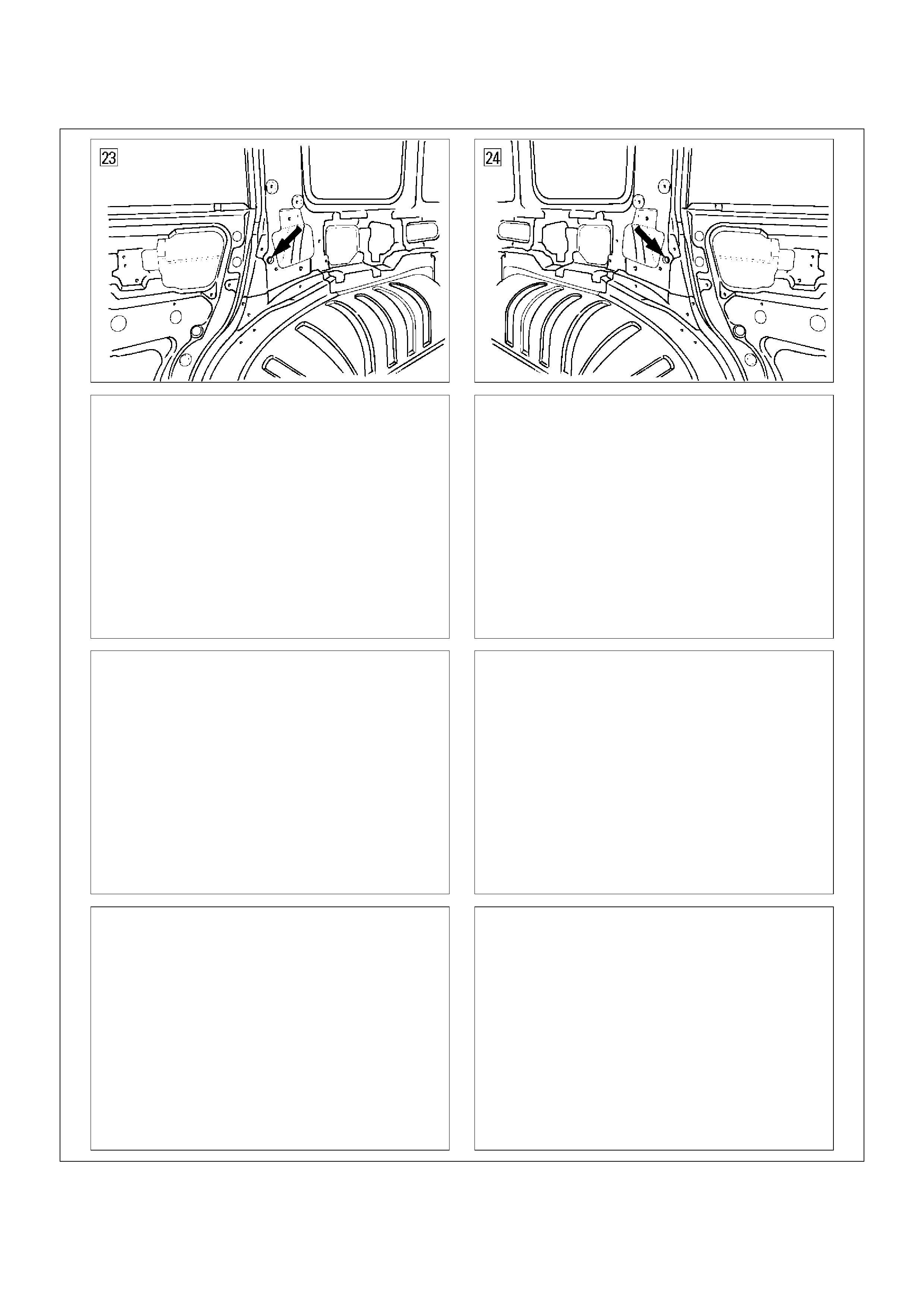
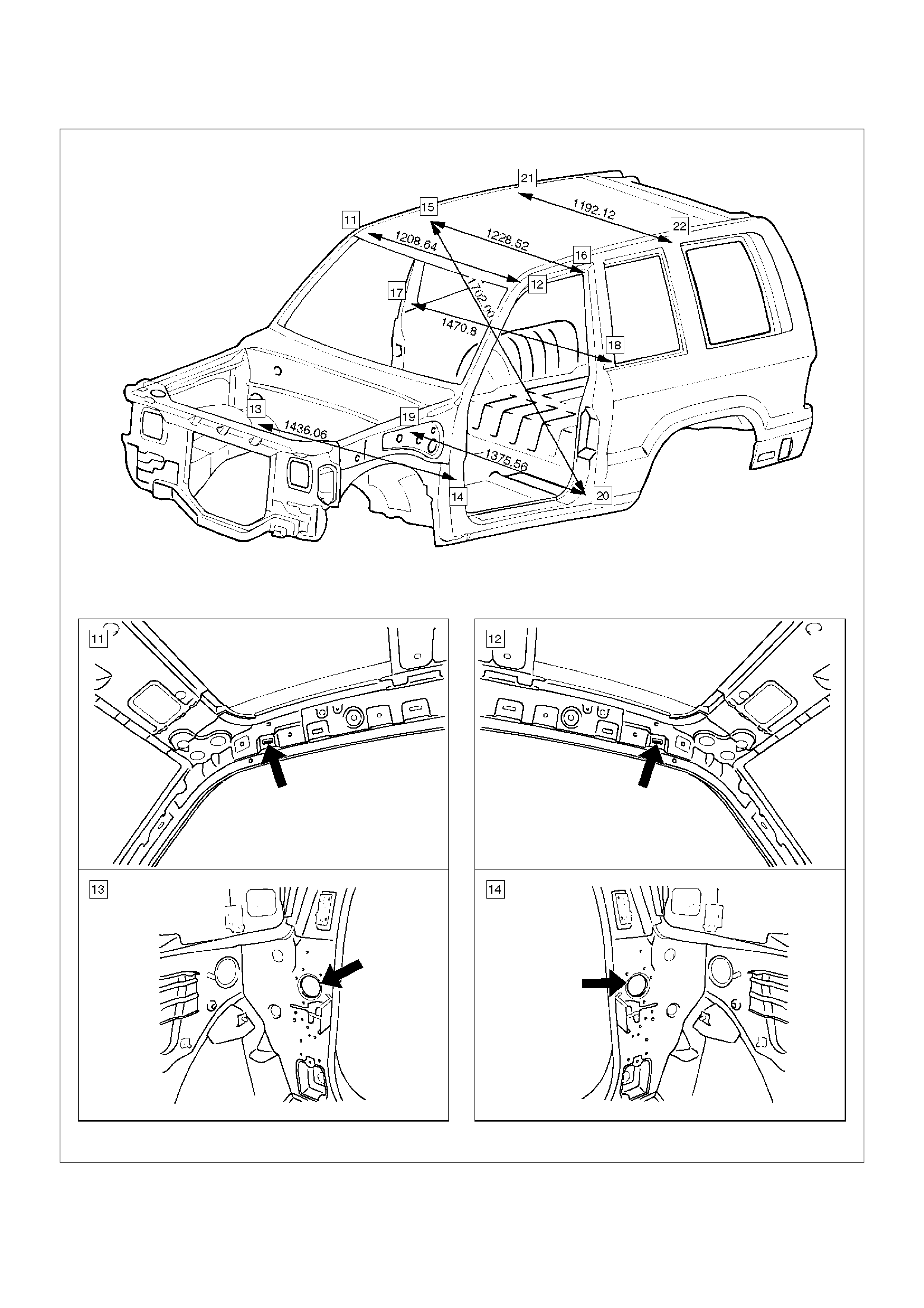
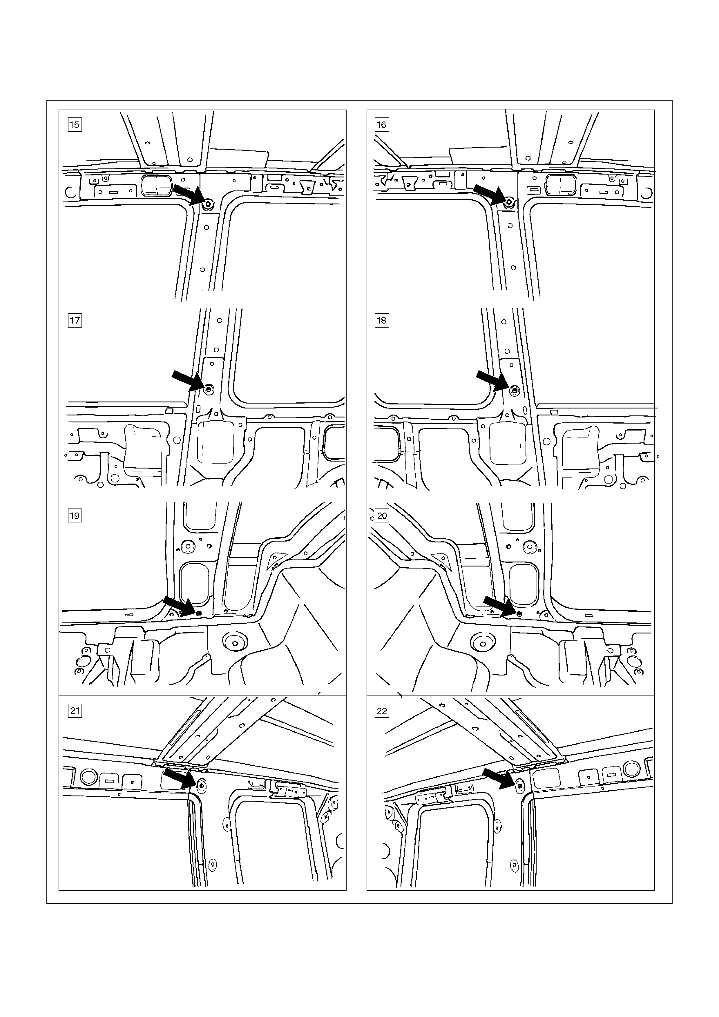
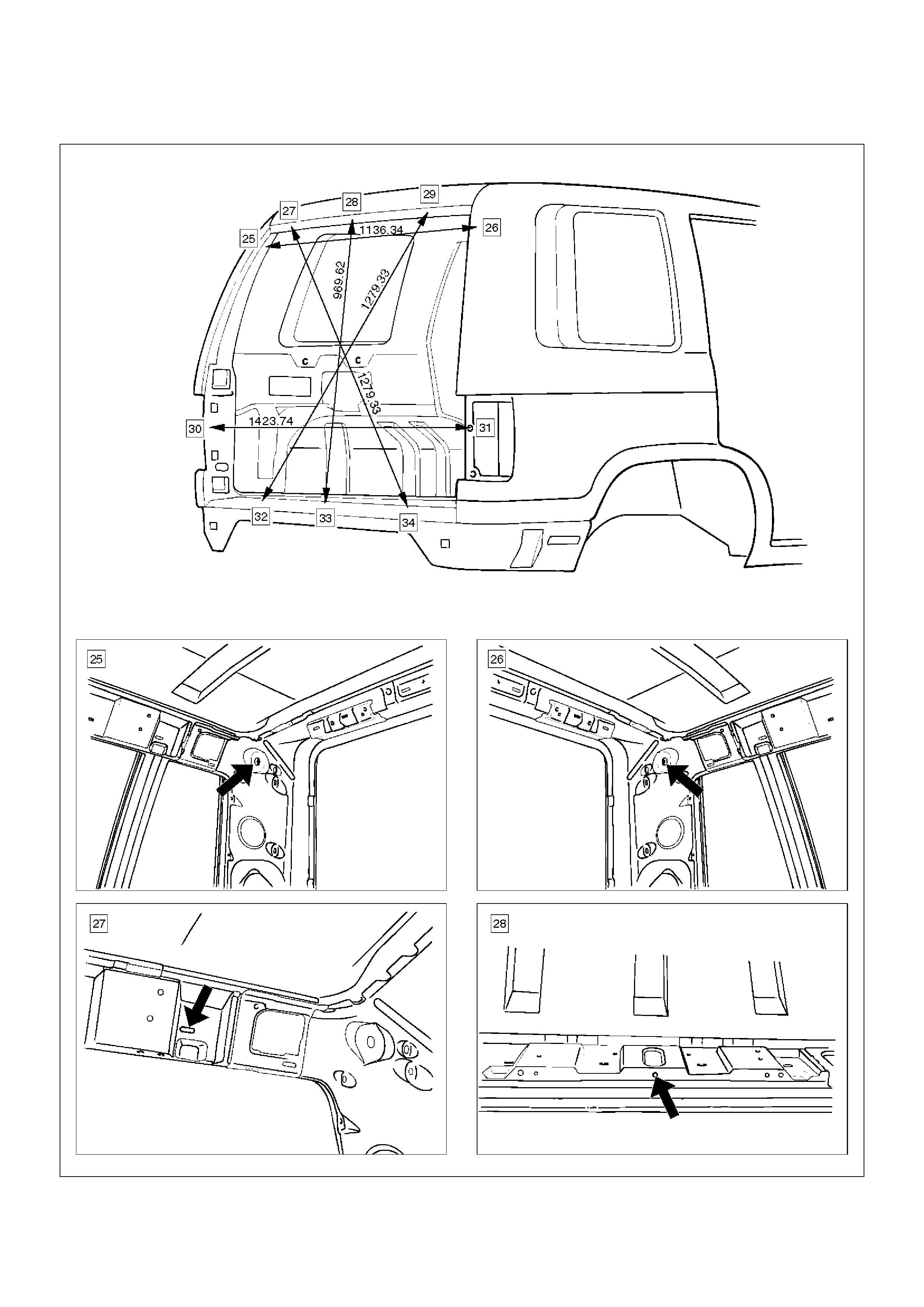
General Description
Body Dimension
Upper Body
Front Section
Room Section (LWB)
Rear Section
Side Body
Window Glass
Instrument Panel Assembly
Parts Location
Removal
Installation
Cross Beam Assembly
Parts Location
Removal
Installation
Front Door Assembly
Parts Location
Removal
Installation
Rear Door Assembly
Parts Location
Removal
Installation
Door Strikers
Adjustment
Door Check Arm Assembly (Front & Rear)
Parts Location
Removal
Installation
Front Window Regulator, Glass And Glass Run
Parts Location
Removal
Installation
Rear Window Regulator And Glass
Parts Location
Removal
Installation
Rear Door Fixed Glass And Glass Run
Parts Location
Removal
Installation
Front Door Sash Moulding
Parts Location
tRemoval
Installation
Techline
Techline

Rear Door Moulding
Parts Location
Removal
Installation
Front Door Waist Seal
Parts Location
Removal
Installation
Rear Door Waist Seal
Parts Location
Removal and Installation
Front Door Weatherstrip
Parts Location
Removal
Installation
Rear Door Weatherstrip
Parts Location
Removal and Installation
Front Door Seal Finisher
Parts Location
Removal
Installation
Rear Door Seal Finisher
Parts Location
Removal
Installation
Tailgate Assembly (LH)
Parts Location
Removal
Installation
Tailgate Assembly (RH)
Parts Location
Removal
Installation
Tailgate Strikers
Adjustment
Tailgate Stopper Assembly
Parts Location
Removal
Installation
Tailgate Dove-Tail
Parts Location
Removal
Installation
Tailgate Dove-Tail Striker
Adjustment
Tailgate Frame Cover (LH)
Parts Location
Removal
Installation
Tailgate Frame Cover (RH)
Removal
Installation
Tailgate Sash Trim Cover
Parts Location
Removal
Installation
Tailgate Outer Weatherstrip
Parts Location
Removal
Installation
Tailgate Center Weatherstrip
Parts Location
Removal
Installation
Tailgate Main Weatherstrip
Parts Location
Removal
Installation
Spare Tire Carrier
Parts Location
Removal
Installation
Headlining
Parts Location
Removal
Installation
Rear Air Deflector
Parts Location
Removal
Installation
Roof Moulding
Parts Location
Removal
Installation
Windshield
Parts Location
Removal
Installation
Rear Quarter Side Glass
Parts Location
Removal
Installation
Tailgate Glass
Parts Location
Removal
Installation
Main Data and Specifications
Special Tools

Service Precaution
WARNING: THIS VEHICLE HAS A SUPPLEMENTAL
RESTRAINT SYSTEM (SRS). REFER TO THE SRS
COMPONENT AND WIRING LOCATION VIEW IN
ORDER TO DETERMINE WHETHER YOU ARE
PERFORMING SERVICE ON OR NEAR THE SRS
COMPONENTS OR THE SRS WIRING. WHEN YOU
ARE PERFORMING SERVICE ON OR NEAR THE
SRS COMPONENTS OR THE SRS WIRING, REFER
TO THE SRS SERVICE INFORMATION. FAILURE TO
FOLLOW WARNINGS COULD RESULT IN POSSIBLE
AIR BAG DEPLOYMENT, PERSONAL INJURY, OR
OTHERWISE UNNEEDED SRS SYSTEM REPAIRS.
CAUTION: Always use the correct fastener in the
proper location. When you replace a fastener, use
ONLY the exact part number for that application.
HOLDEN will call out those fasteners that require a
replacement after removal.HOLDEN will also call
out the fasteners that require thread lockers or
thread sealant. UNLESS OTHERWISE SPECIFIED,
do not use supplemental coatings (Paints, greases,
or other corrosion inhibitors) on threaded fasteners
or fastener joint interfaces. Generally, such
coatings adversely affect the fastener torque and
the joint clamping force, and may damage the
fastener. When you install fasteners, use the correct
tightening sequence and specifications. Following
these instructions can help you avoid damage to
parts and systems.
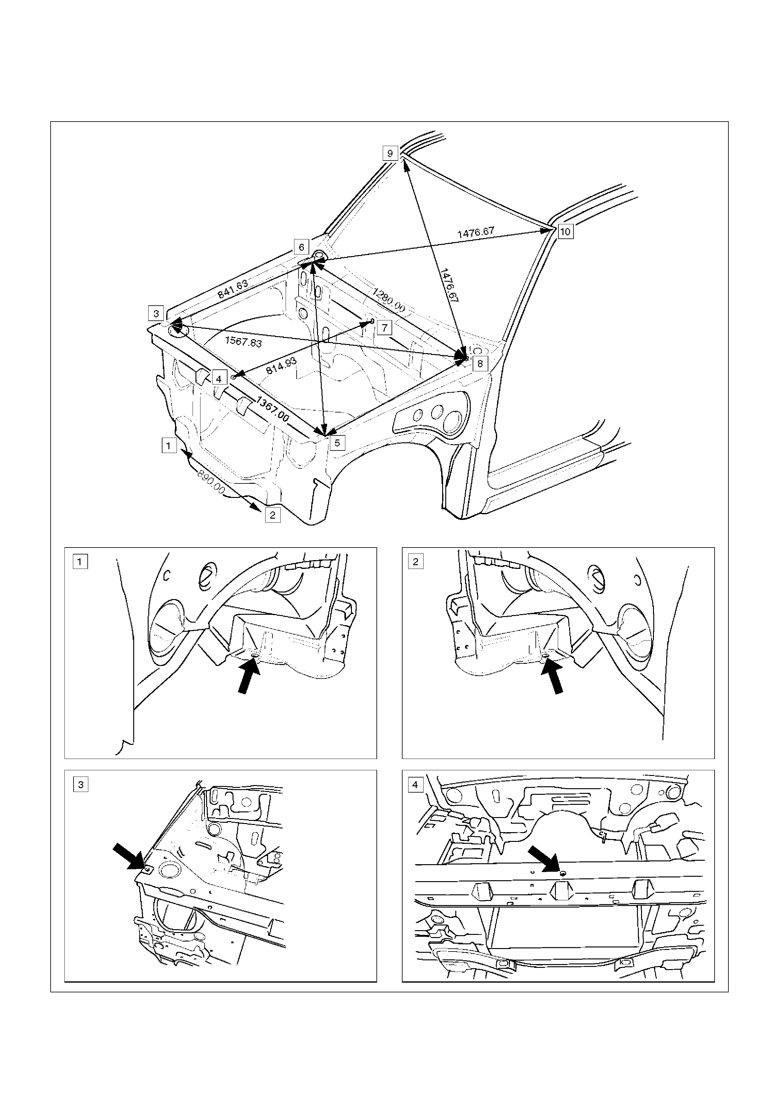
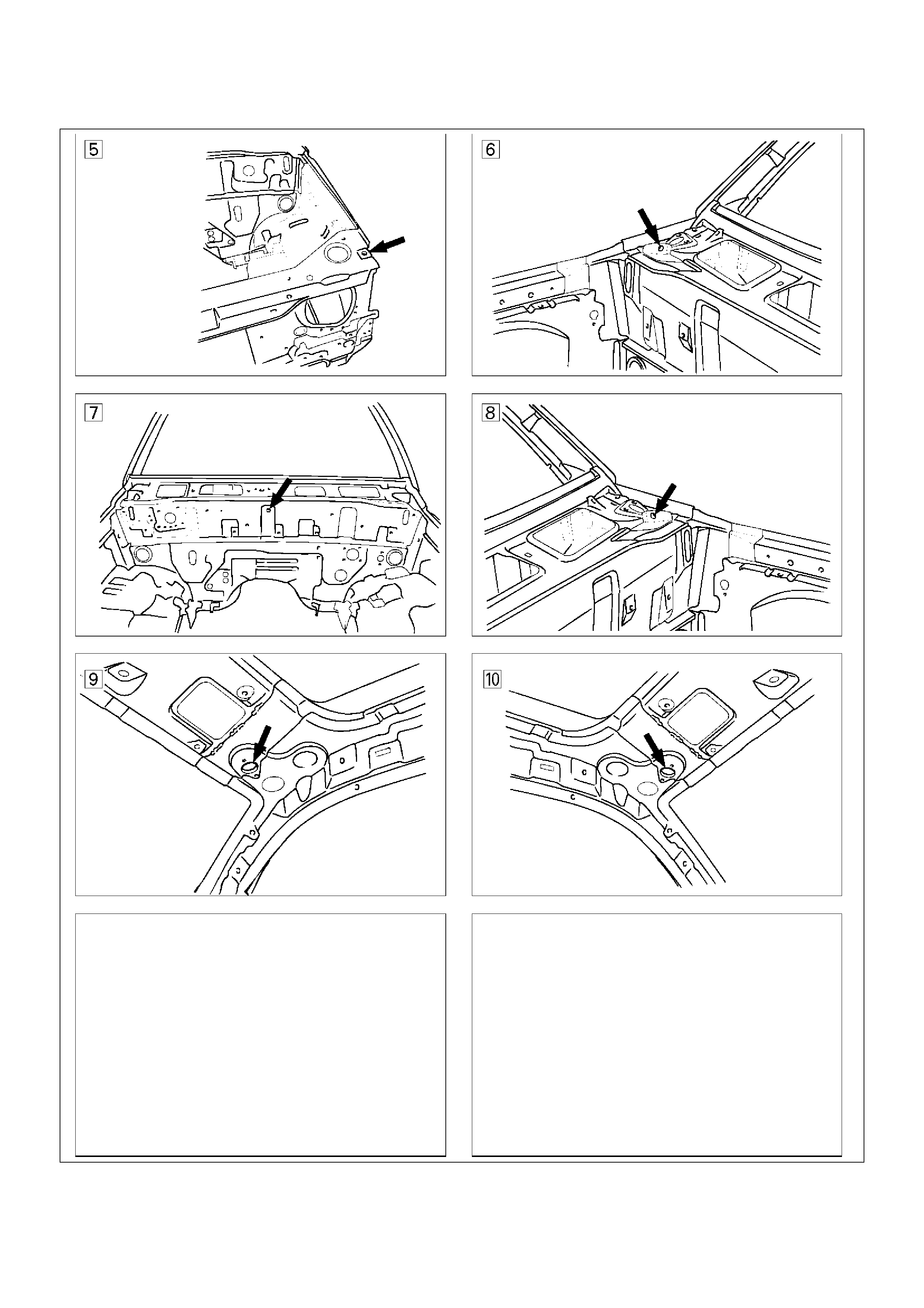
Frame
General Description
Proper frame alignment is important to assure normal
vehicle life and performance of many other parts of the
vehicle. If the vehicle has been involved in a fire,
collision or has been overloaded, it is necessary to
check the frame alignment.
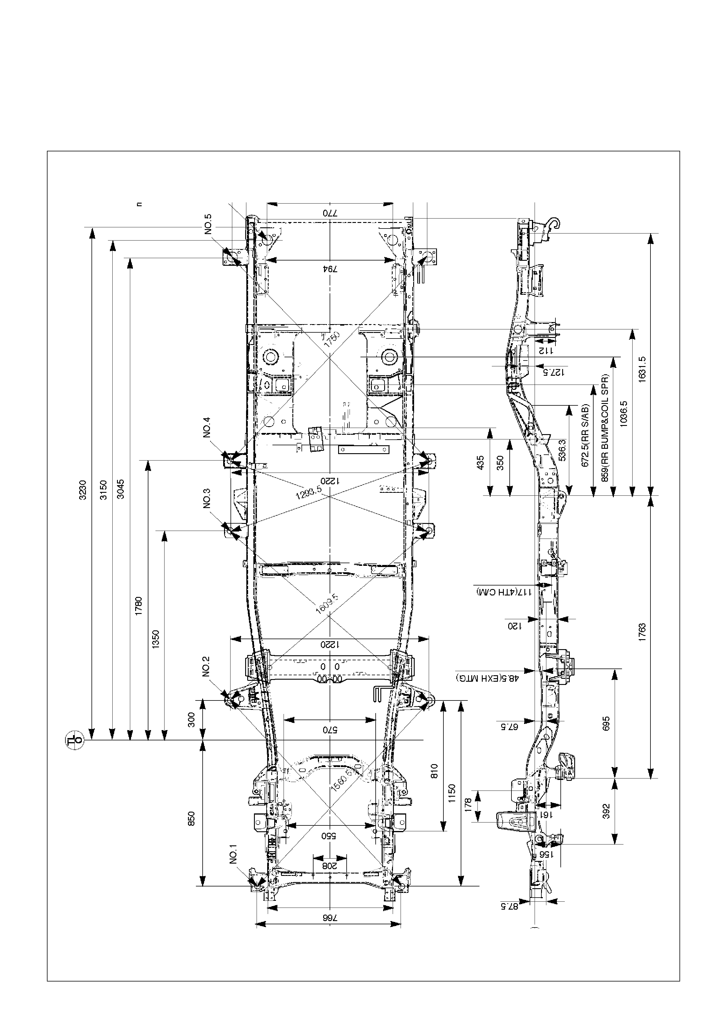
Frame Dimensions (L W B)
This illustration is based on the gasoline engine and A/T
model.
501RW013
General Description
This section describes how to remove and install front
and rear bumpers. Each bumper is installed with two
fixing bolts used on either side to fasten the backbar to
the frame, a slider is used to fasten the bumper fascia to
the fender panel. The bumpers can be removed by
taking them out forward or backward after removing the
two fixing bolts on either side.
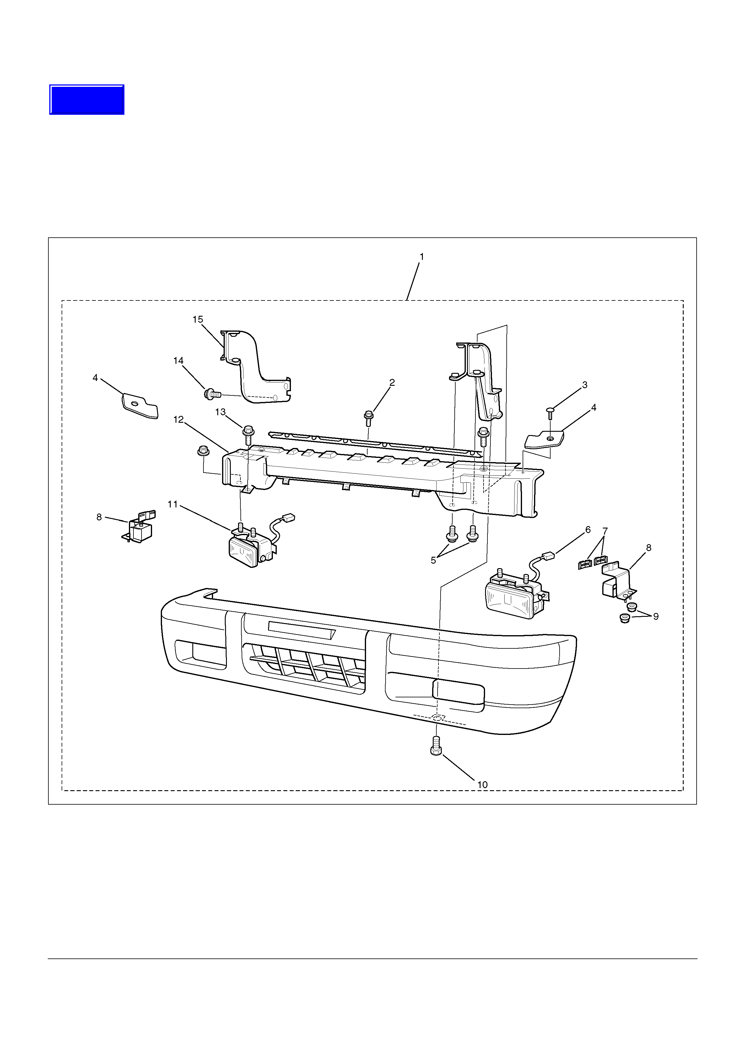
Front Bumper
Parts Location
601RX001
EndOFCallout
Legend
(1) Front Bumper Assembly
(2) Front Bumper Retainer Bolt
(3) Support Fixing Clip
(4) Bumper Spacer Support
(5) Back Bar Fixing Bolt
(6) Front Fog Light Connector
(7) Front Bumper Slider Fixing Clip
(8) Front Bumper Slider
(9) Front Bumper Slider Fixing Nut
(10) Bumper Fascia Lower Bolt
(11) Front Fog Light Assembly
(12) Reinforce Assembly
(13) Reinforce Lower Bolt
(14) Front Bumper Fixing Bolt
(15) Back Bar
Techline
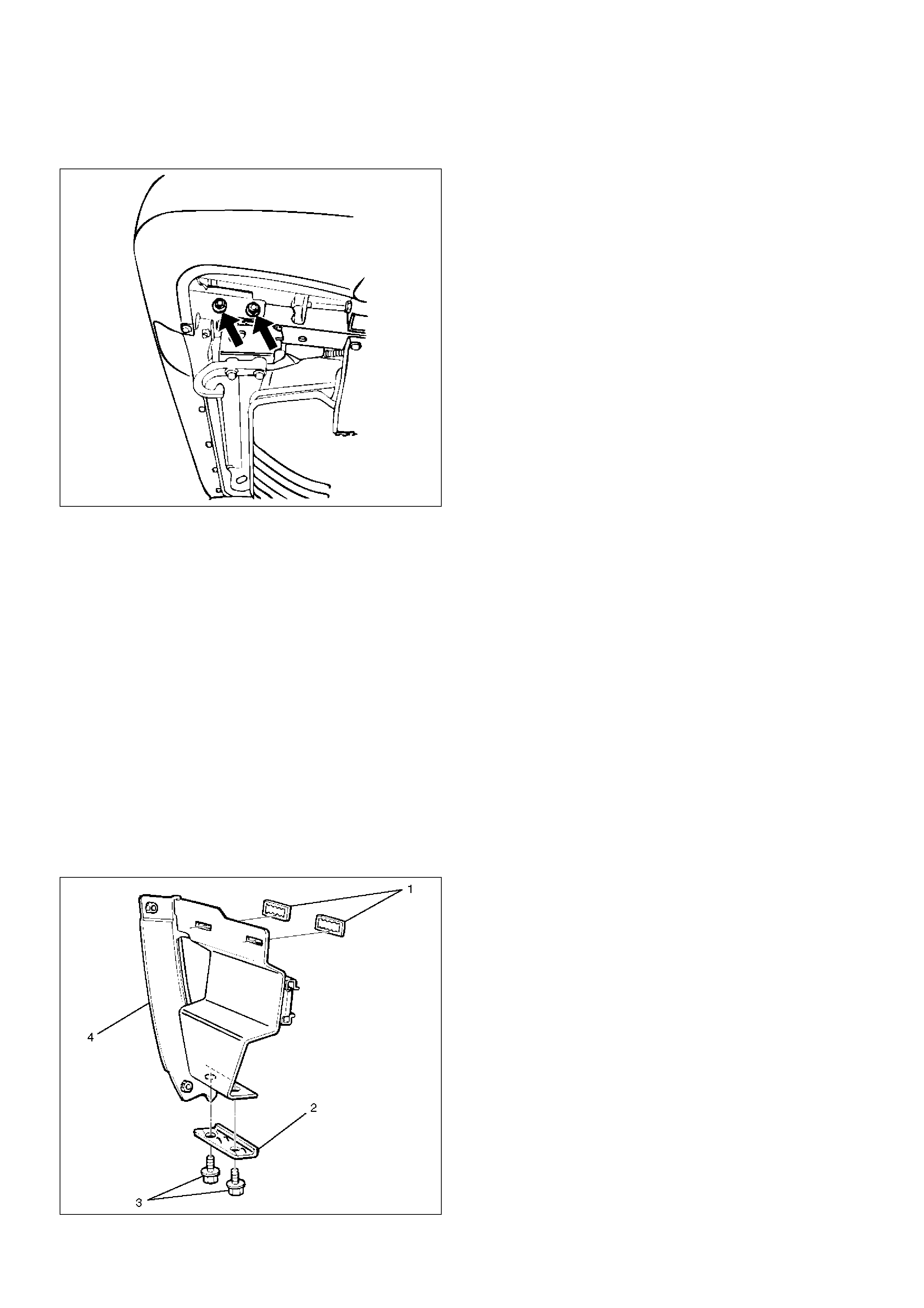
Removal
1.Disconnect battery ground cable.
2.Remove front fog light connector.
3.Remove front bumper assembly fixing bolt.
•Remove the two bolts from both sides of the front
bumper.
601RW010
4.Remove front bumper assembly.
5.Remove bumper fascia lower bolts.
6.Remove front bumper retainer.
7.Remove reinforce lower bolts.
•Loosen the five bolts and release claws.
8.Remove reinforce assembly.
9.Remove backbar fixing bolts.
•Remove the four bolts at each backbar.
10.Remove front fog light assembly.
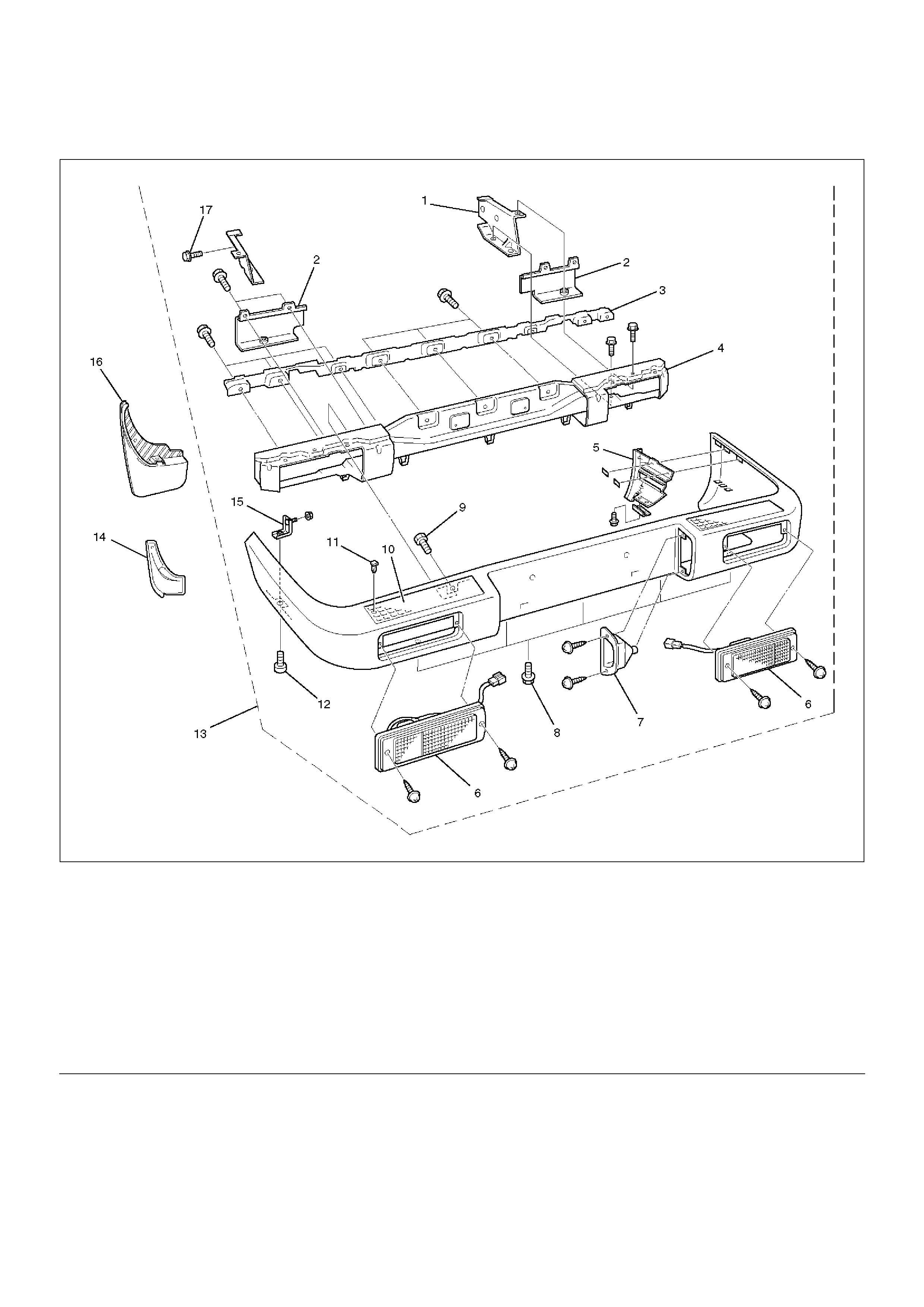
11.Remove the front bumper slider(1).
•Remove the two clips(4) and the two nuts(3), and
release the claw from the washer(2).
601RW009
Installation
To install, follow the removal steps in reverse order
noting the following points:
1.Tighten the front bumper assembly fixing bolts to the
specified torque.
Torque: 132N•m (13.5kg·m/98lbft)
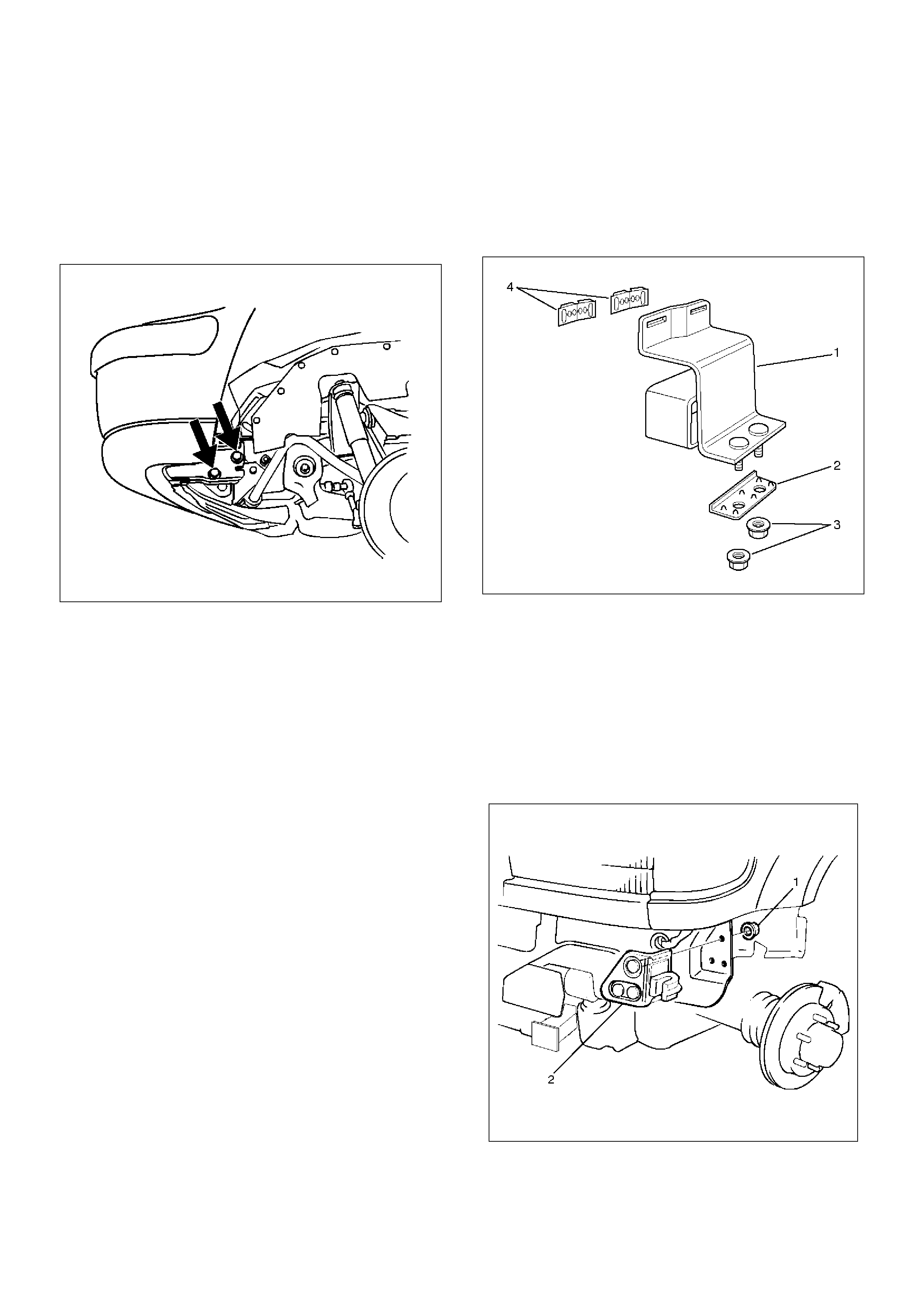
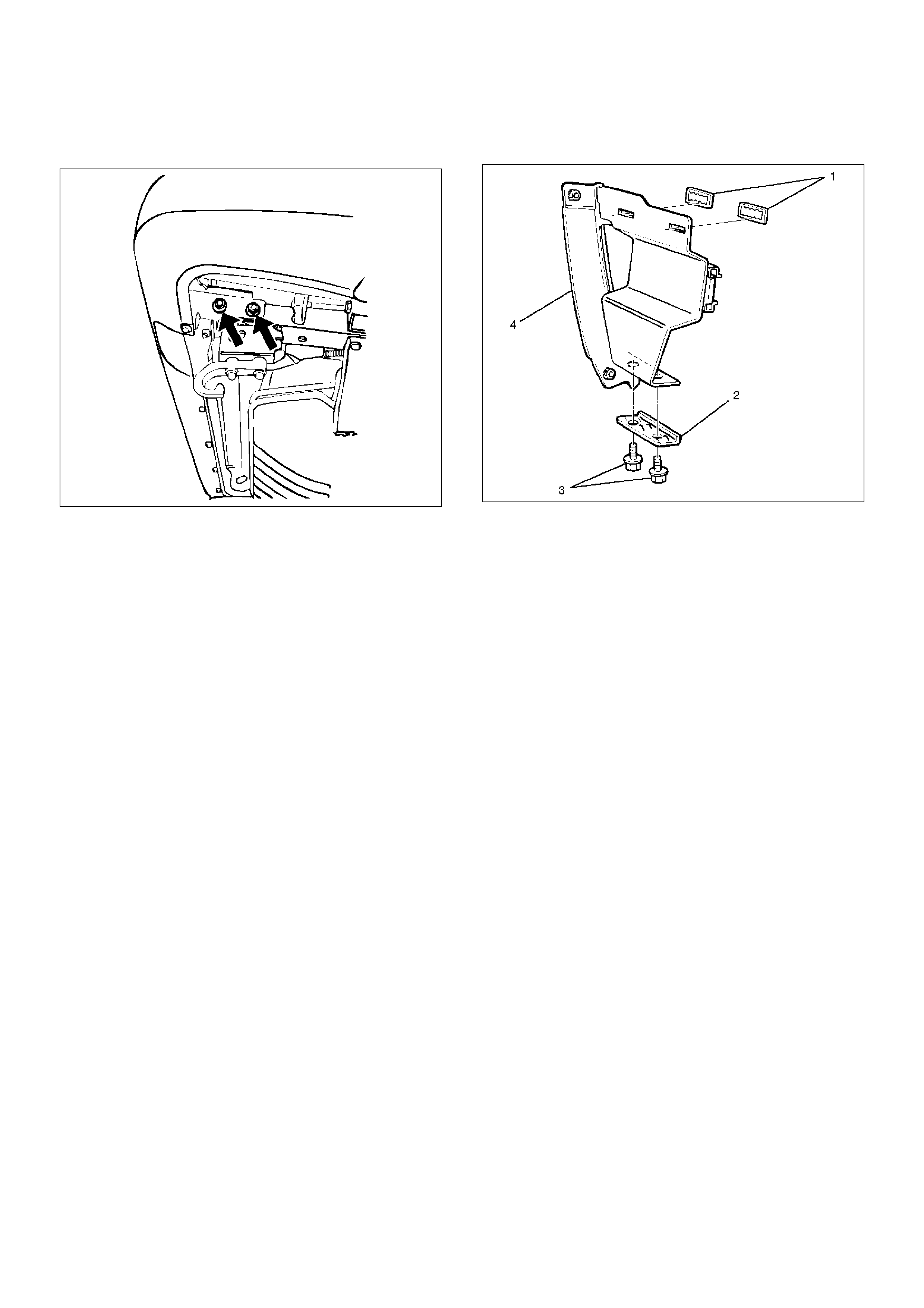
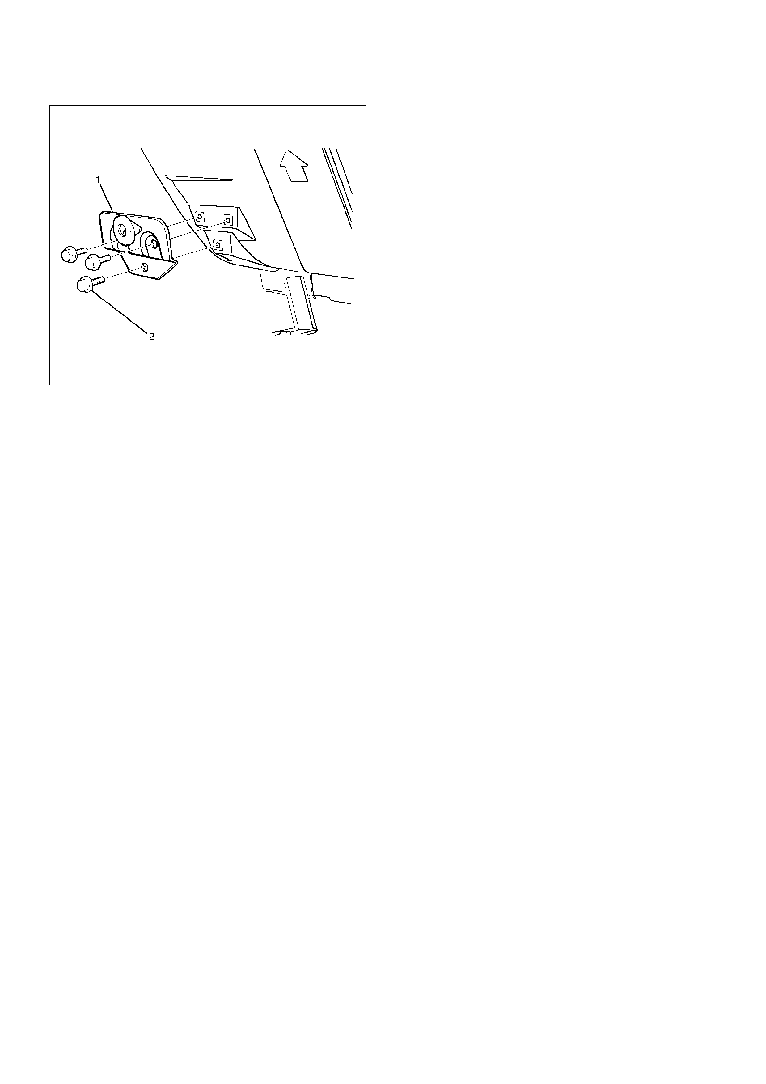
Front Bumper Slider Bracket
Removal
1.Disconnect battery ground cable.
2.Remove the Front bumper.
•Refer to Front Bumper in this section.
3. Remove the three nuts(1) and draw out the slider
bracket(2).
601RW003
Installation
To install, follow the removal steps in reverse order.
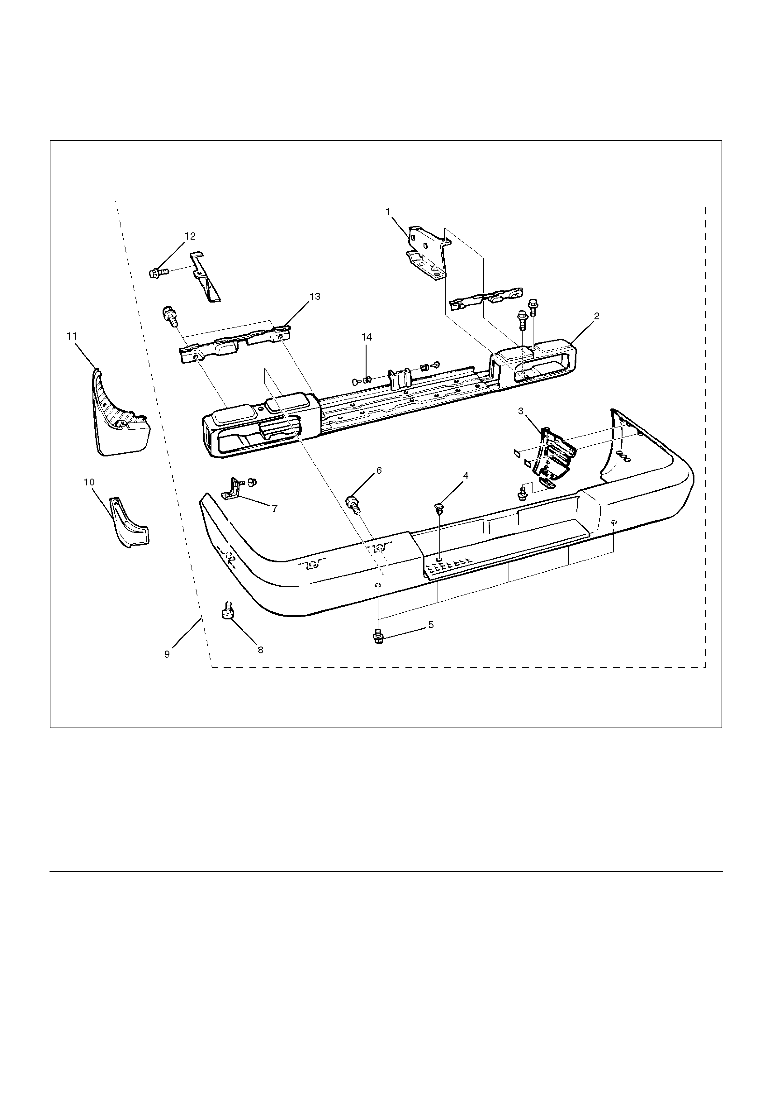
Rear Bumper
Parts Location
690RW001
EndOFCallout
Removal
1. Remove rear bumper side covers.
2. Remove mud flaps.
• Remove three screws.
3. Remove bumper fascia bracket screws.
Legend
(1) Back Bars
(2) Reinforce Assembly
(3) Rear Bumper Slider Brackets
(4) Rear Step Clips
(5) Reinforce Lower Screws
(6) Reinforce Upper Bolts
(7) Rear Bumper Fascia Brackets
(8) Rear Bumper Fascia Bracket Screws
(9) Rear Bumper Assembly
(10) Rear Bumper Side Covers
(11) Mud Flaps
(12) Rear Bumper Assembly Fixing Bolts
(13) Rear Bumper Retainers
(14) Clips
4. Remove rear bumper assembly fixing bolts.
• Remove two bolts from each side.
690RW002
5. Remove rear bumper assembly.
6. Remove rear bumper retainers.
7. Remove reinforce upper bolts.
• Remove the rear bumper retainer from each side,
and then remove two upper bolts.
8. Remove reinforce lower screws.
9. Remove clips.
10. Remove rear step clips.
11. Remove reinforce assembly.
• Pull out both ends of the bumper fascia and take
out the reinforce assembly.
12. Remove backbars.
• Remove the three bolts from each backbar.
13. Remove rear bumper slider brackets(4).
• Remove the two clips(1) and two screws(3), and
then remove claw caught in the washer(2).
690RS003
14. Remove bumper fascia brackets.
• Remove the fixing nut on the back side of the
fender panel.
Installation
To install, follow the removal steps in reverse order
noting the following points:
1. Tighten the rear bumper assembly fixing bolts to the
specified torque.
Torque: 132N•m (13.5kg·m/98lbft)
2. Apply chassis grease to the slider and the slider
bracket moving surface.
Parts Location (W/Rear Combination Light and License Light)
690RW010
EndOFCallout
Removal
1. Disconnect battery ground cable.
2. Remove rear bumper side covers.
3. Remove mud flaps.
• Remove three screws.
4. Remove rear bumper fascia bracket screws.
Legend
(1) Back Bar
(2) Rear Combination Light Back Plate
(3) Rear Bumper Retainer
(4) Reinforce Assembly
(5) Rear Bumper Slider Brackets
(6) Rear Combination Light Assembly
(7) License Light
(8) Reinforce Lower Screws
(9) Reinforce Upper Bolts
(10) Rear Step
(11) Rear Step Clips
(12) Rear Bumper Fascia Bracket Screws
(13) Rear Bumper Assembly
(14) Rear Bumper Side Covers
(15) Rear Bumper Fascia Brackets
(16) Mud Flaps
(17) Rear Bumper Assembly Fixing Bolts
5.Remove rear bumper assembly fixing bolts.
•Remove two bolts from each side.
690RW002
6.Remove rear bumper assembly.
7.Remove rear bumper retainers.
8.Remove rear combination light back plate.
9.Remove reinforce upper bolts.
•Remove the rear bumper retainer from each side,
and then remove two upper bolts.
10.Remove reinforce lower screws.
11.Remove rear step clips.
12.Remove rear step.
13.Remove reinforce assembly.
•Pull out both ends of the bumper fascia and take
out the reinforce assembly.
14.Remove backbars.
•Remove the three bolts from each backbar.
15.Remove rear bumper slider brackets(4).
•Remove the two clips(1) and two screws(3), and
then remove claw caught in the washer(2).
690RS003
16.Remove bumper fascia brackets.
•Remove the fixing nut on the back side of the
fender panel.
17.Remove rear combination light assembly.
18.Remove license light.
Installation
To install, follow the removal steps in reverse order
noting the following points:
1.Tighten the rear bumper assembly fixing bolts to the
specified torque.
Torque: 132N•m (13.5kg·m/98lbft)
2.Apply chassis grease to the slider and the slider
bracket moving surface.
Rear Bumper Slider
Removal
1.Remove the rear bumper.
•Refer to Rear Bumper removal in this section.
2. Remove the three bolts (2).
3. Remove rear bumper slider (1).
690RS004
Installation
To install, follow the removal steps in reverse order
noting the following points:
1. Apply chassis grease to the slider and the slider
bracket moving surface.
General Description
This section includes items of front end sheet metal that
are attached by bolts, screws or clips and related
accessory components.
Anti-corrosion materials have been applied to the
interior surfaces of some metal panels to provide rust
resistance. When servicing these panels, areas on
which this material has been disturbed should be
properly recoated with service-type anti-corrosion
material.
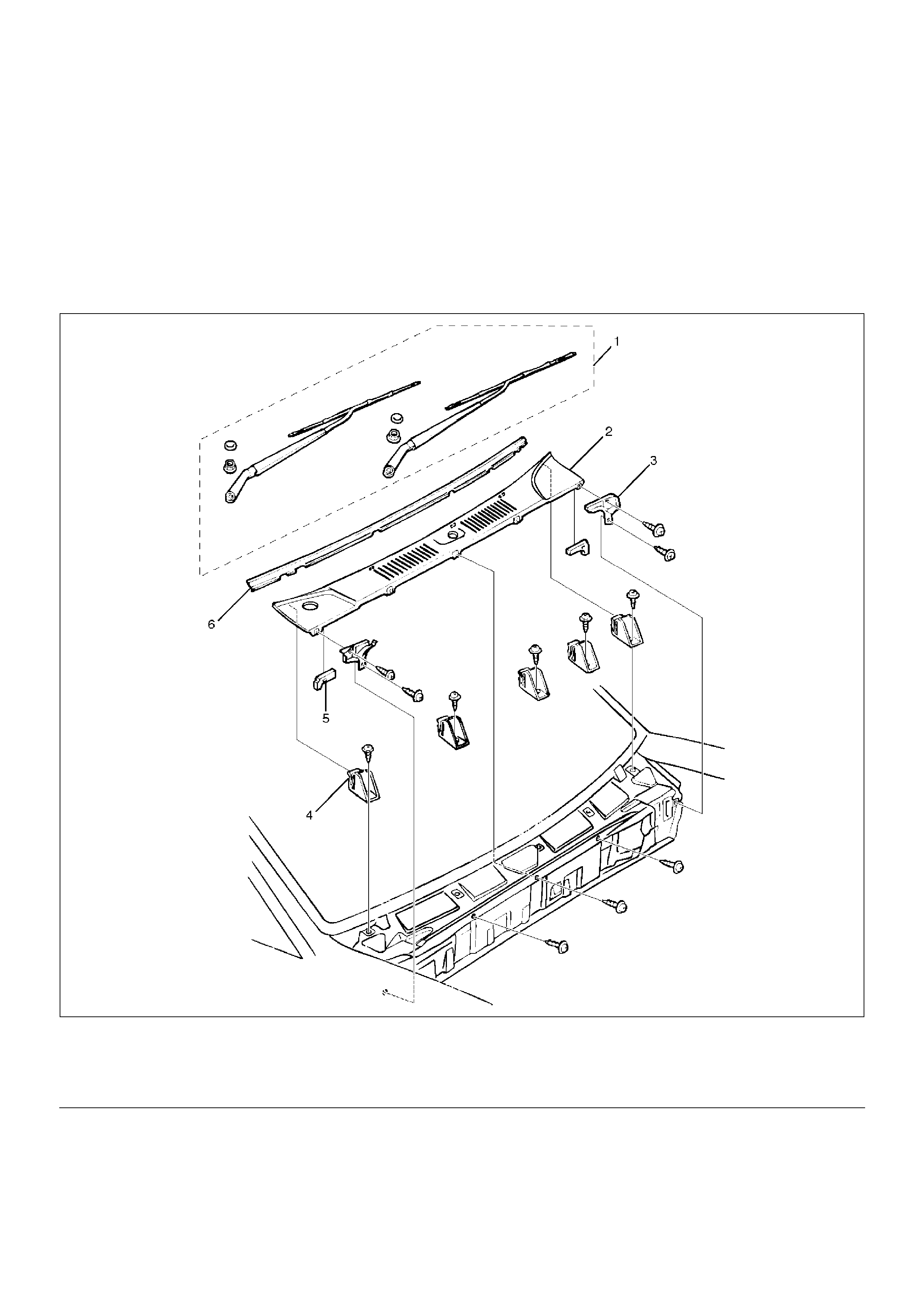
Cowl Cover
Parts Location
605RW009
EndOFCallout
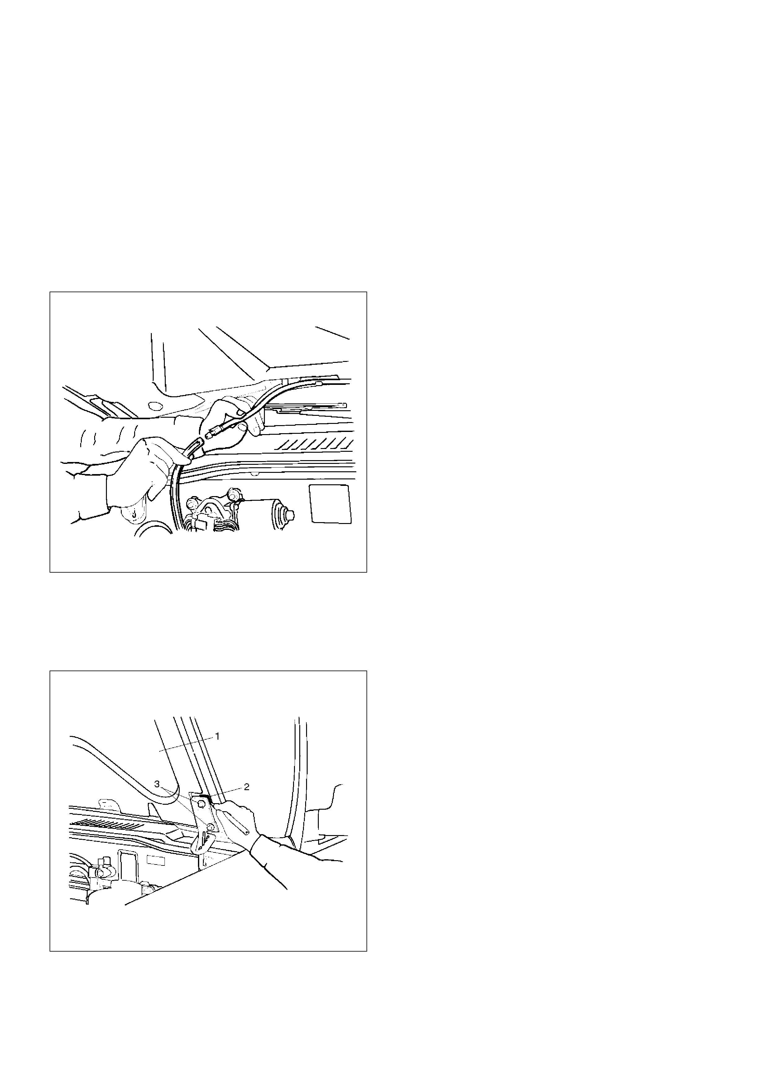
Removal
1.Open the hood.
2.Support the hood.
3.Remove front wiper arms.
•Refer to Windshield Wiper Arm/Blade in Wiper/
Washer System section.
4. Remove cowl cover brackets.
• Disconnect two screws each side.
Legend
(1) Front Wiper Arms
(2) Cowl Cover
(3) Cowl Cover Brackets
(4) Cowl Cover Stoppers
(5) Cowl Cover Seals
(6) Front Window Lower Molding
5.Remove cowl cover.
•Disconnect three screws.
6.Remove cowl cover seals.
7.Remove front window lower molding.
8.Remove cowl cover stoppers.
Installation
To install, follow the removal steps in reverse order.
Engine Hood
Removal
1.Open the hood.
2.Support the hood.
3.Remove windowshield washer nozzle tube.
880RS001
4.Remove hood hinge bolts (3).
•Before removing the hinges from the engine hood
(1), scribe a mark (2) showing location of the
hinges to facilitate installation in the original
position.
610RS003
5.Remove engine hood.
Installation
To install, follow the removal steps in the reverse order
noting the following points:
1.Tighten the engine hood fixing bolts to the specified
torque.
Torque: 13N•m (1.3kg·m/113lbin)
2.Adjust the engine hood mounting gap with reference
to Body Dimension in this section.
3. Check and see if the engine hood lock operates
normally.
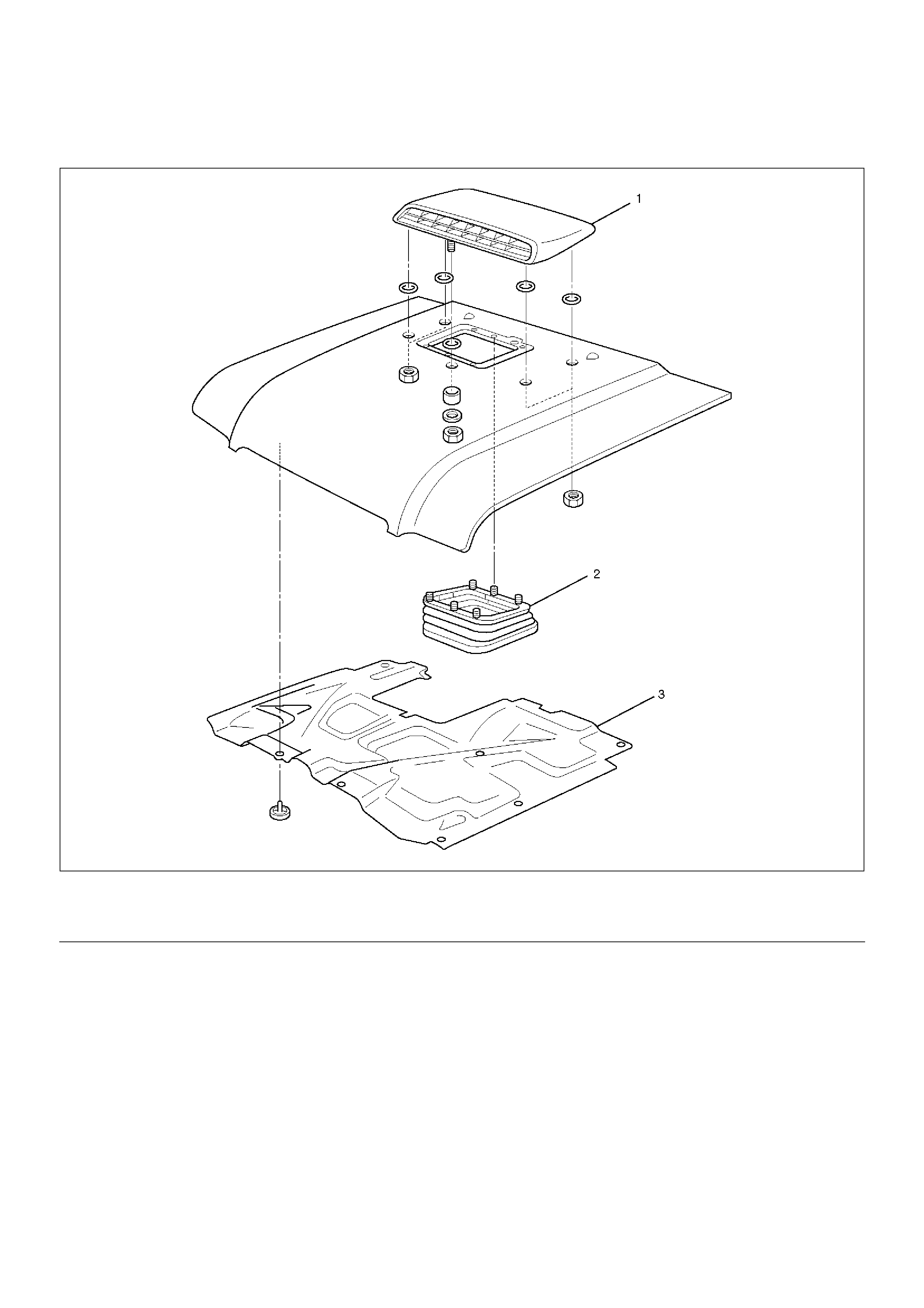
Air Bulge
Parts Location
610RW013
EndOFCallout
Removal
1. Remove engine food insulator.
• Remove the sixteen clips.
2. Remove Intercooler seal.
• Remove the six clips.
3. Remove air bulge.
• Remove the six nuts.
Installation
To install, follow the removal steps in the reverse order
noting the following points:
1. Tighten the air bulge fixing nuts to the specified
torgue.
Torque 8 N•m (0.8kg·m/ 69lbin)
Legend
(1) Air Bulge
(2) Intercooler Seal
(3) Engine Hood Insulator
Engine Hood Hinge
Parts Location
610RW012
EndOFCallout
Removal
1.Remove cowl cover.
• Refer to Cowl Cover in this section.
2. Remove engine hood.
•Refer to Engine Hood in this section.
3. Remove hinge fixing bolt and nut.
4. Remove engine hood hinge.
5. Remove hood end seal.
Installation
To install, follow the removal steps in reverse order
noting the following points:
1. Tighten the hood hinge fixing bolt and nut to the
specified torque.
Torque 13 N•m (1.3kg·m/113lbin)
Legend
(1) Hinge Fixing Bolts And Nuts
(2) Hood End Seal
(3) Engine Hood Hinge
(4) Engine Hood
(5) Cowl Cover
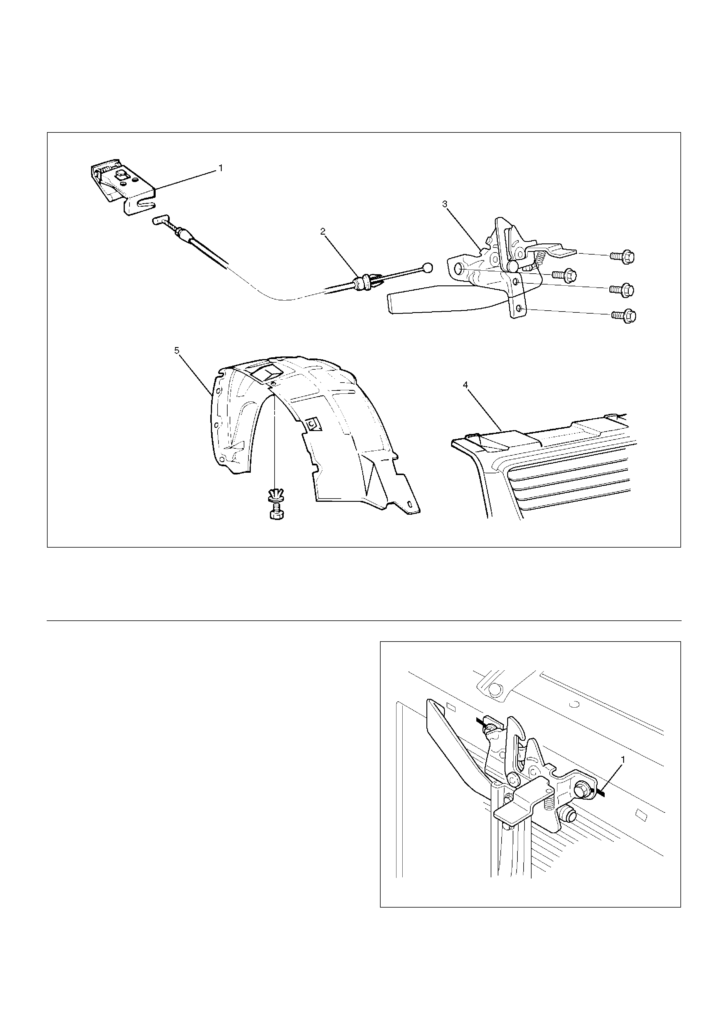
Engine Hood Lock
Parts Location
610RW011
EndOFCallout
Removal
1.Remove hood lock control lever.
2.Remove inner liner.
3.Remove control cable.
•Remove the cable fixing clips from the body
panel.
4.Remove radiator grille.
•Refer to Radiator Grille And Front End Lower
Panel in this section.
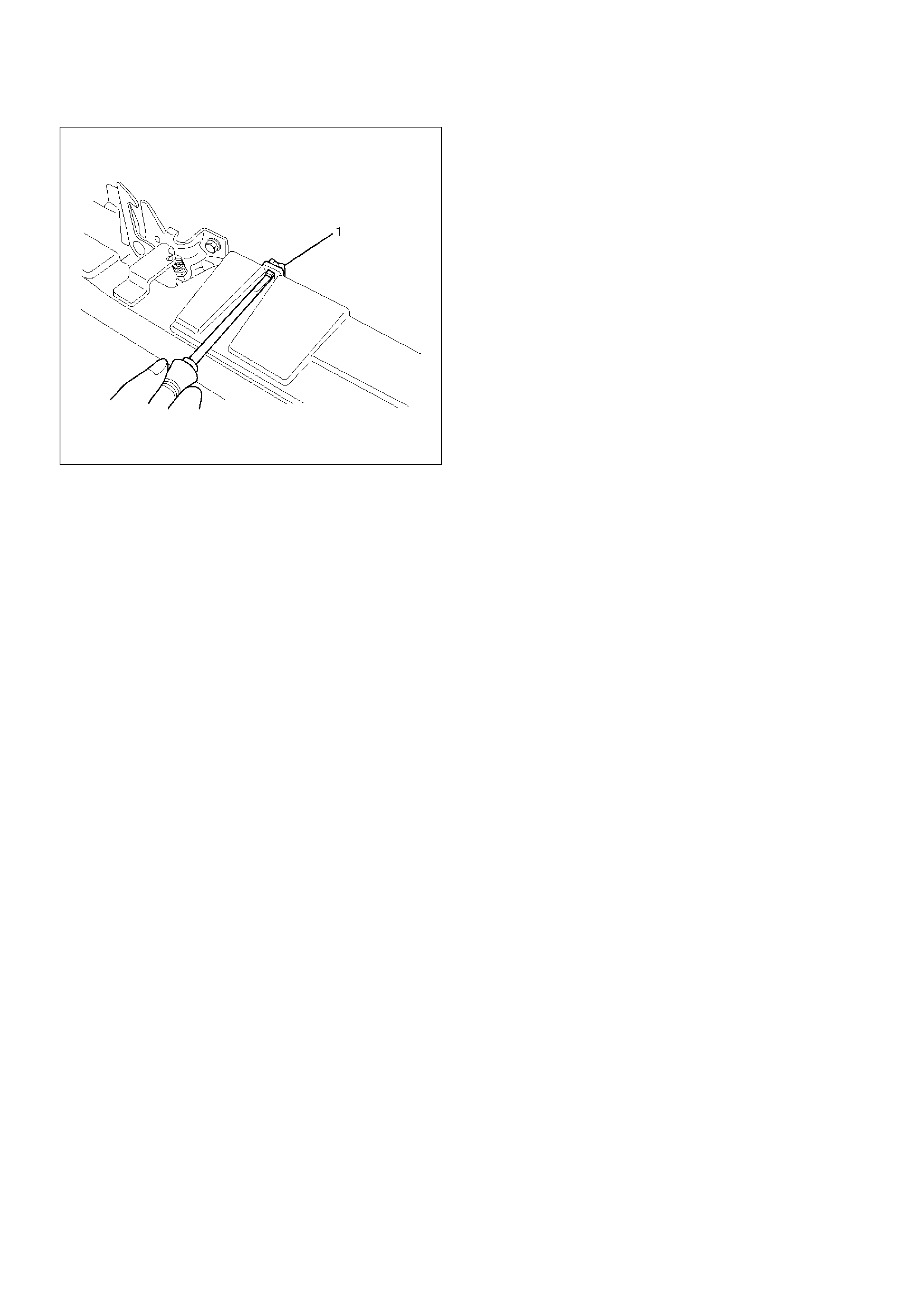
5. Remove engine hood lock assembly.
• Apply setting marks (1) to the hood lock
assembly and the body prior to removal.
610RW009
Legend
(1) Hood Lock Control Lever
(2) Control Cable
(3) Engine Hood Lock Assembly
(4) Radiator Grille
(5) Inner Liner
Installation
To install, follow the removal steps in reverse order
noting the following points:
1.Reroute the control cable to its original position, and
check and see if the lock assembly and control
lever work normally.
2.Tighten the hood lock assembly fixing bolts to the
specified torque.
Torque : 10N•m (1.0kg·m/87lbin)
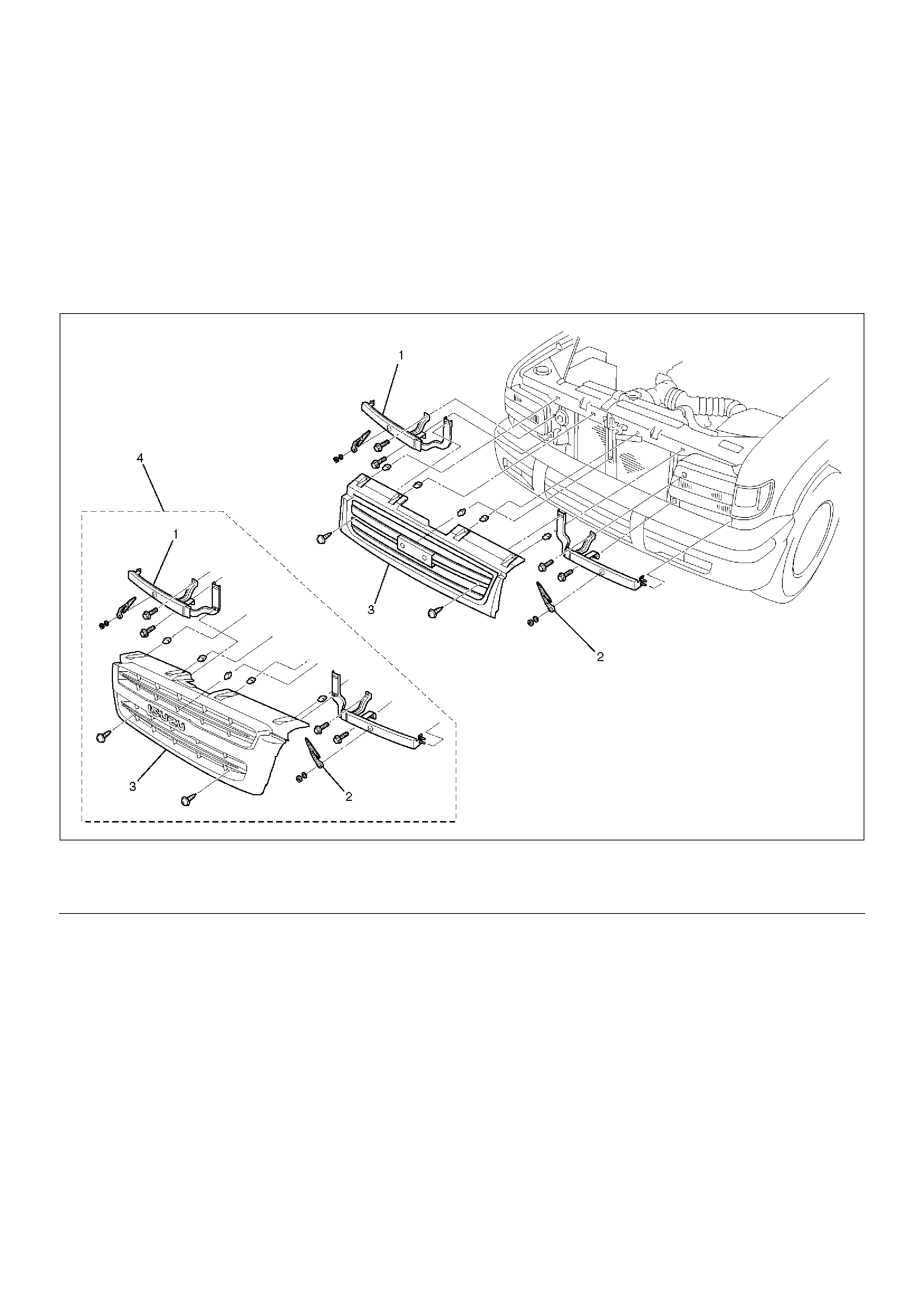
Radiator Grille And Front End Lower Panel
Parts Location
603RY00002
EndOFCallout
Removal
1.Open the hood.
2.Support the hood.
3.Remove headlight wiper.
•Refer to Headlight Wiper Arm & Blade in Wiper/
Washer System section.
4. Remove radiator grille.
• Raise the clips (1) on the radiator grille and
remove two screws.
Legend
(1) Front End Lower Panel
(2) Head Light Wiper
(3) Radiator Grille
(4) For ISUZU Brand Vehicle Only
603RW012
5. Remove front end lower panel.
• Remove two fixing bolts and remove the panel
from the fender.
Installation
To install, follow the removal steps in reverse order,
noting the following point.
1. Install the radiator grille clips remaining on the body
side in the radiator grille, and then install the
radiator grille on the body.
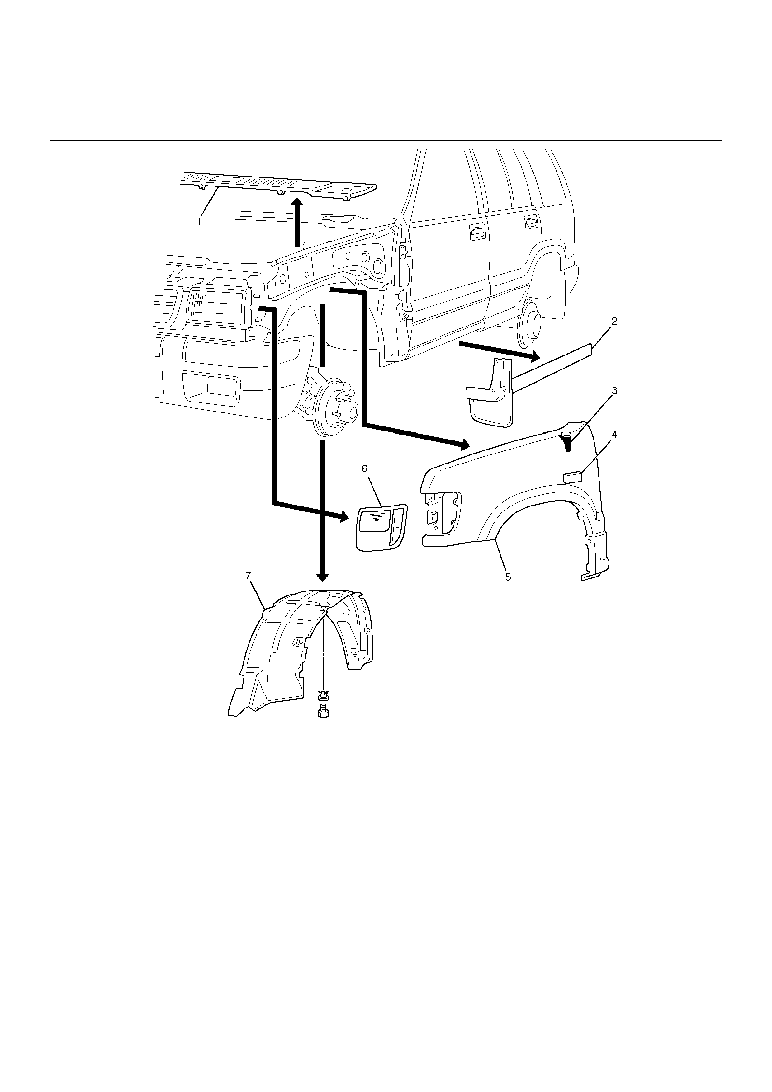
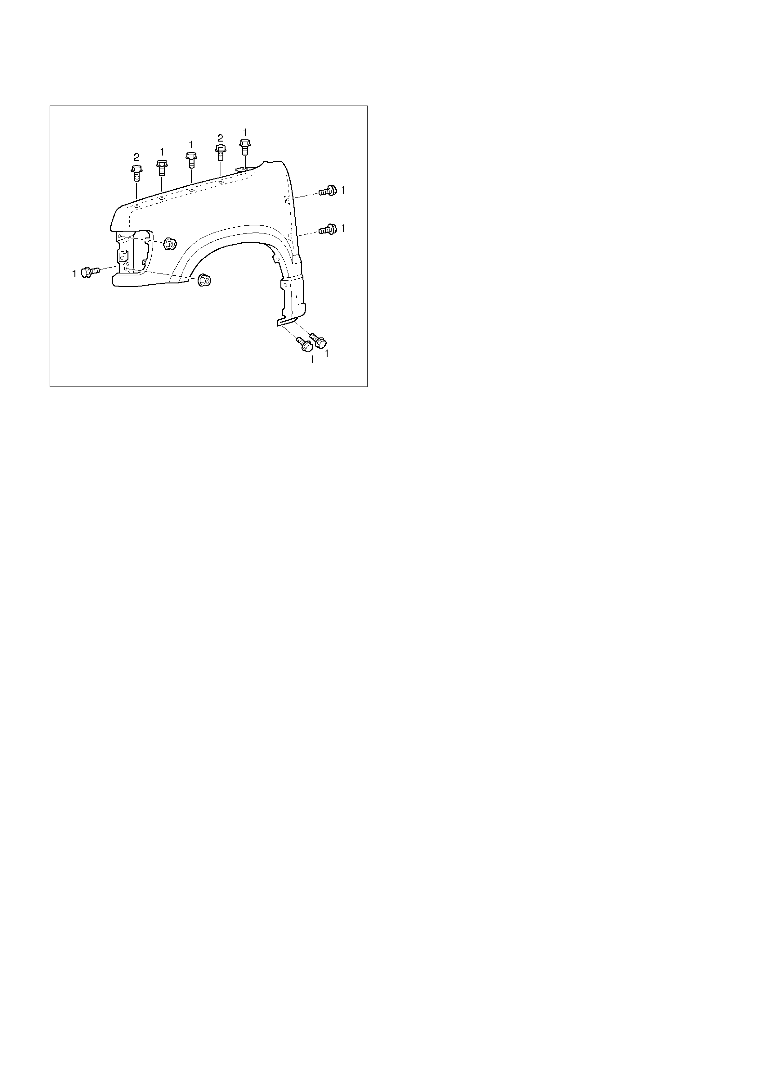
Front Fender Panel
Parts Location
605RW008
EndOFCallout
Removal
1.Open the hood.
2.Support the hood.
3.Disconnect the battery ground cable.
4.Remove cowl cover.
•Refer to Cowl Cover in this section.
5.Remove front combination lamp assembly.
•Disconnect fixing screw and connector.
6.Remove front mud flap.
•Disconnect three fixing screws and four clips.
7.Remove inner liner.
8.Remove antenna bezel.
•Refer to Antenna in Entertainment section.
9.Remove side turn signal light.
•Refer to Side Turn Signal Light Bulb in Lighting
System section.
10. Remove front fender panel.
• Disconnect ten fixing bolts and two nuts.
Legend
(1) Cowl Cover
(2) Front Mud Flap
(3) Antenna Bezel
(4) Side Turn Signal Light
(5) Front Fender Panel
(6) Front Combination Light Assembly
(7) Inner Liner
605RW001
Installation
To install, follow the removal steps in the reverse order
noting the following points:
1. Tighten the front fender panel fixing bolts to the
specified torque.
(1) Torque : 9N•m (0.9kg·m/78lbin)
(2) Torque : 7N•m (0.7kg·m/61lbin)
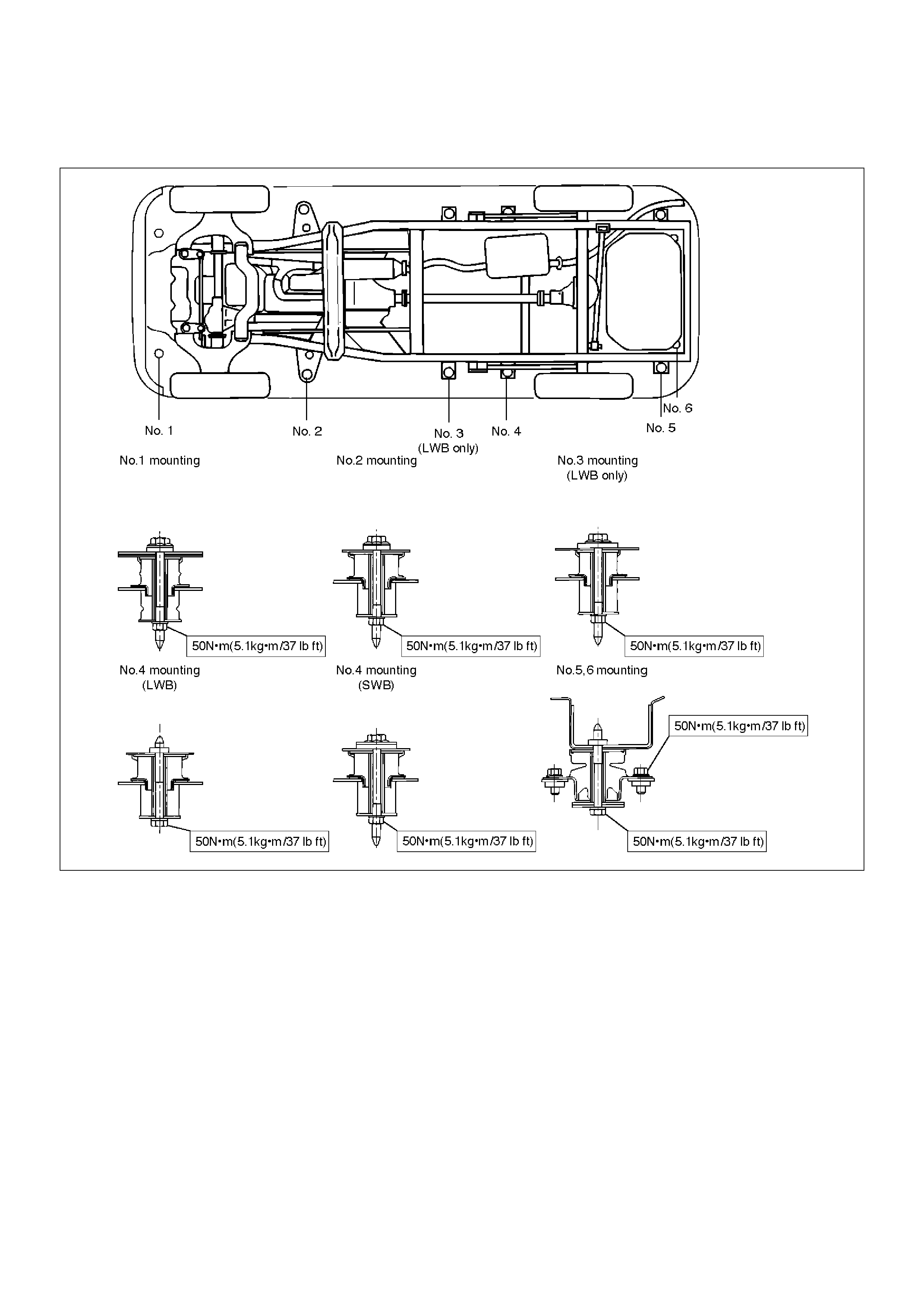
Body Mounting
Parts Location
E02RW006
Removal (No.1 – No. 2)
1. Remove the front bumper.
2. Jack up the vehicle by the frame.
3. Support the front side sill and rear axle with stands.
Further, support the front jack up point with a jack.
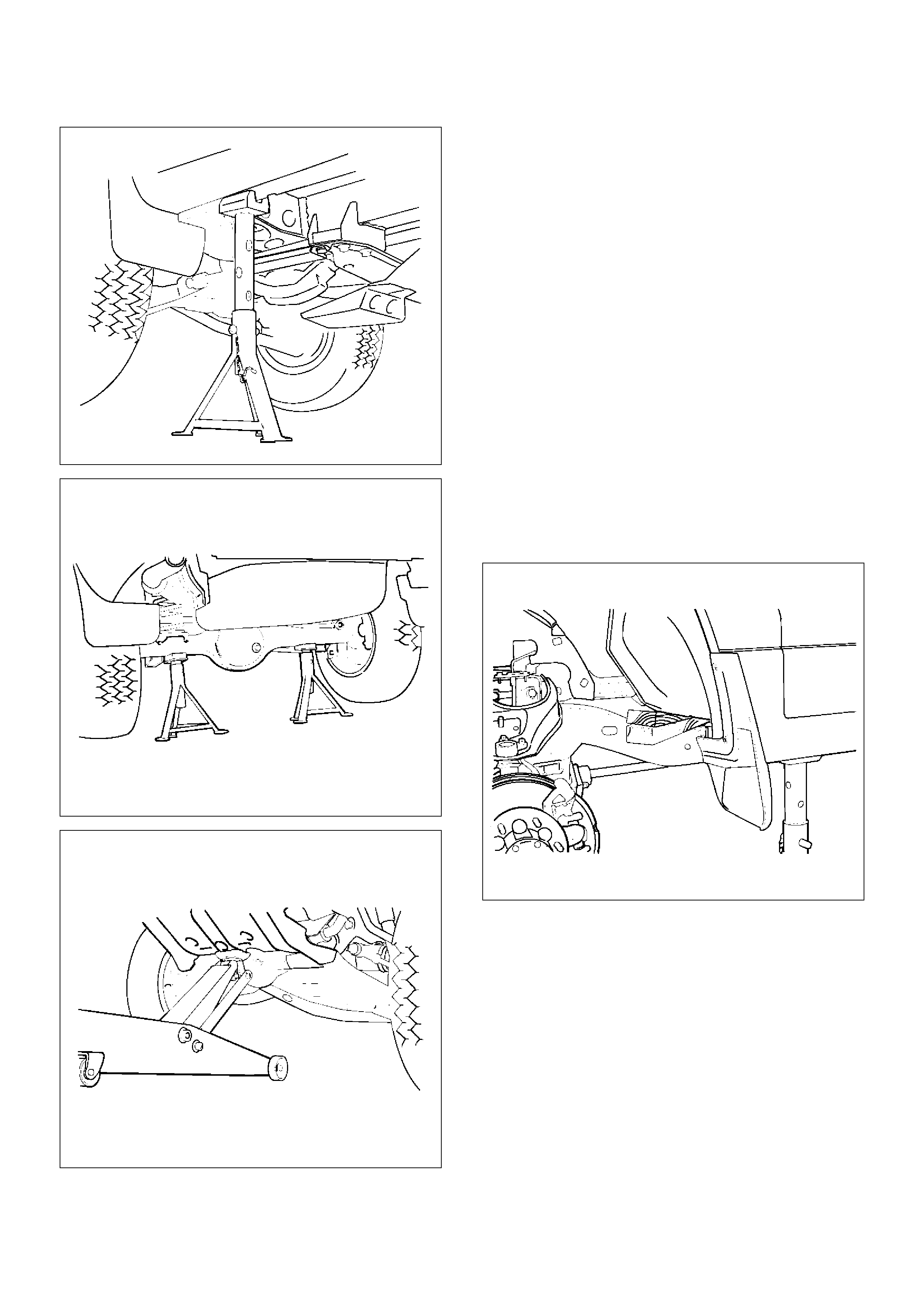
620RS001
420RS001
545RS001
4. Remove the mounting bolts (No. 1-4) on either side.
• No. 1 – Hold in check not to turn from the inside
of the front fender.
• No. 2 – Remove the front door sill plate and dash
side trim panel, turn over the floor carpet and
hold the bolt in check not to turn.
• No. 3 (LWB only)– Remove the rear door sill plate
and center pillar lower trim cover, turn over the
floor carpet and hold the bolt in check not to turn.
• No. 4 (SWB)– Remove the luggage side trim
cover, turn over the floor carpet and hold the bolt
in chek not to turn.
• No. 4 (LWB)– Remove the bolt from under the
frame.
5. Loosen the mounting bolts (No. 5-6) on either side.
6. Remove the frame side mounting and washer.
7. Gently lower the jack supporting the front axle until
the cab side mounting can be removed.
8. Remove the cab side mounting.
• Be sure to use a splice bar around the mounting
to be removed.
501RS001
Removal (No. 3 — No. 6)
1. Remove the rear bumper.
2. Jack up the vehicle by the frame.
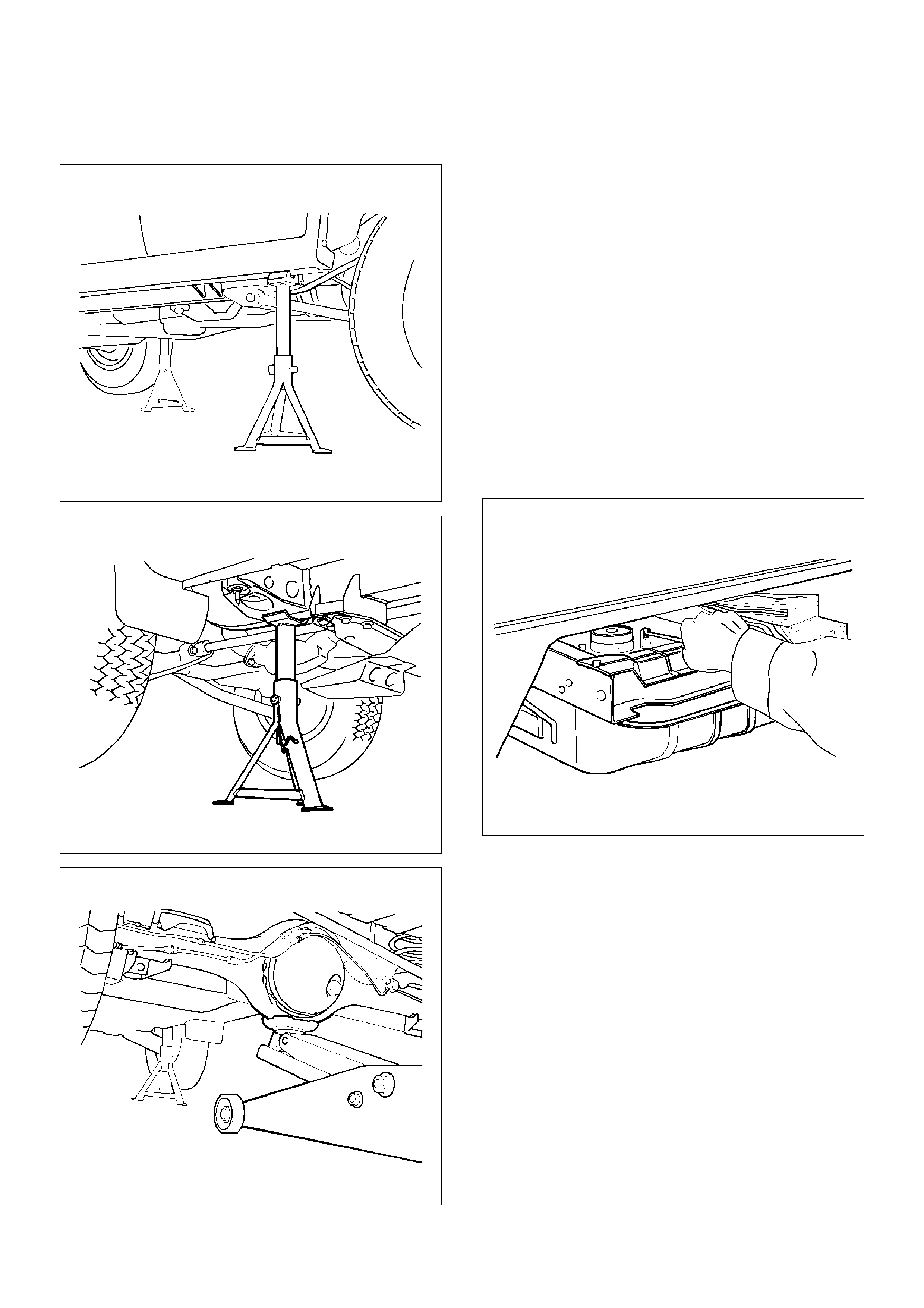
3. Support the rear side sill and frame stands, and
support the rear axle with a jack.
620RS002
501RS003
420RS002
4. Remove the mounting bolts (No. 3-6) on either side.
• No. 3 (LWB only) — Remove the rear door sill
plate and center pillar lower-trim cover, turn over
the floor carpet and hold the bolt in check not to
turn.
• No. 4 (SWB) — Remove the luggage side trim
cover, turn over the floor carpet and hold the bolt
in check not to turn.
• No. 4 (LWB) and No. 5 – 6
5. Remove the frame side mounting and washer.
6. Gently lower the jack supporting the rear axle until
the cab side mounting can be removed.
7. Remove the cab side mounting.
• Be sure to use a splice bar around the mounting
to be removed.
• As for No. 5 and 6, remove the frame side
bracket fixing bolts after lowering the frame
gently.
510RS001
Installation
To install, follow the removal steps in the reverse order,
noting the following point:
1. Tighten each mounting bolt to the specified torque.
Torque : 50N•m (5.1kg·m/37lbft)

General Description
This section describes major items of the removal,
installation and servicing procedures pertaining to the
TROOPER body. Each servicing instruction is
applicable to all models of the TROOPER, unless
otherwise specifically mentioned. For those differing by
specific models from the common procedures, they are
detailed for each model.
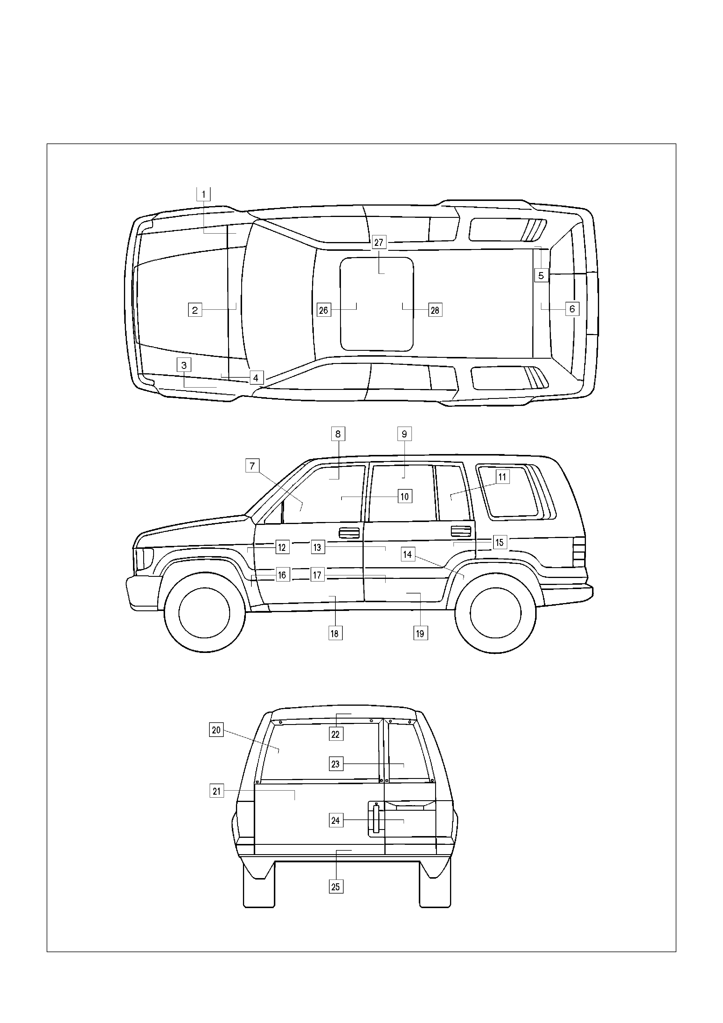
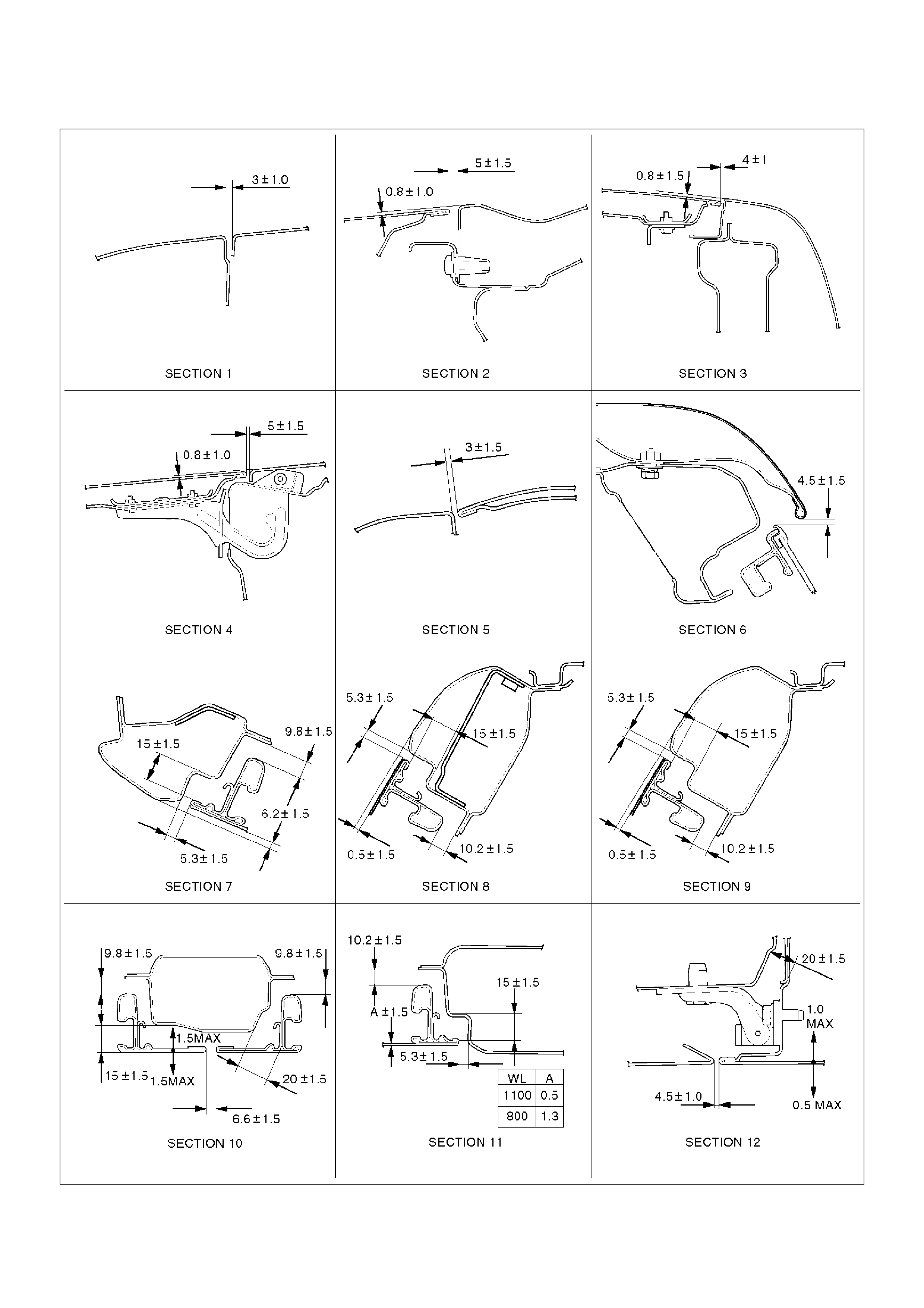
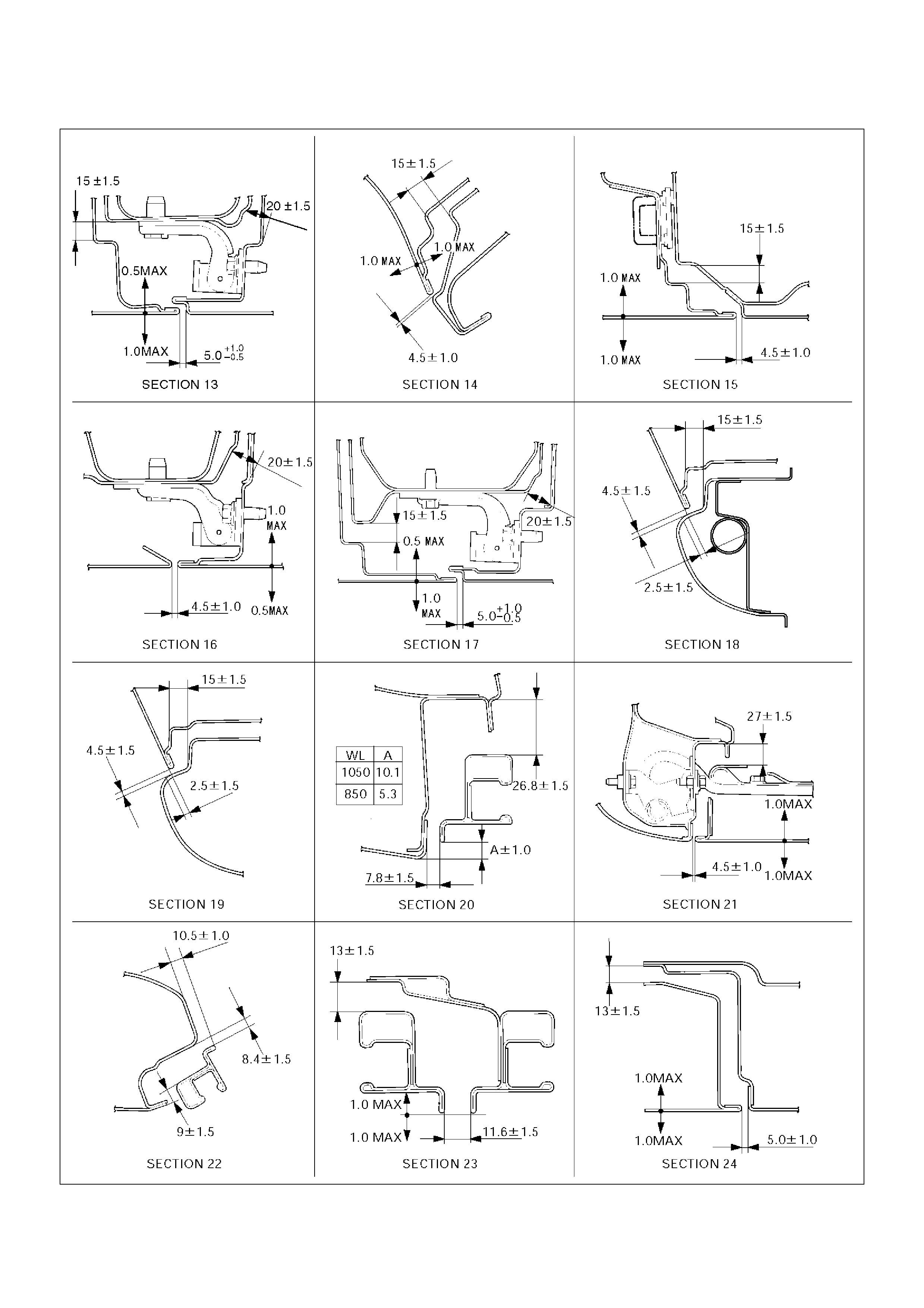
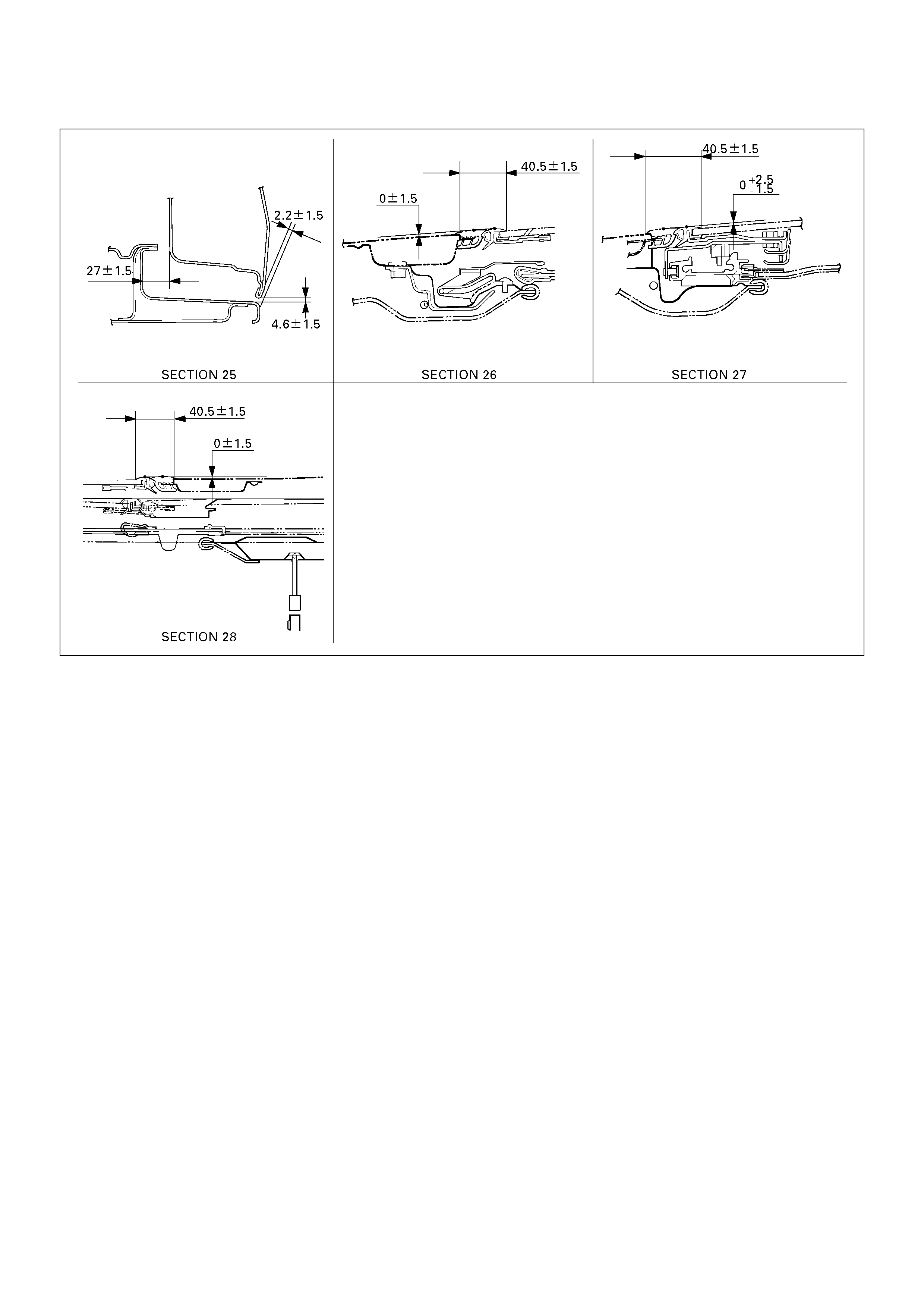
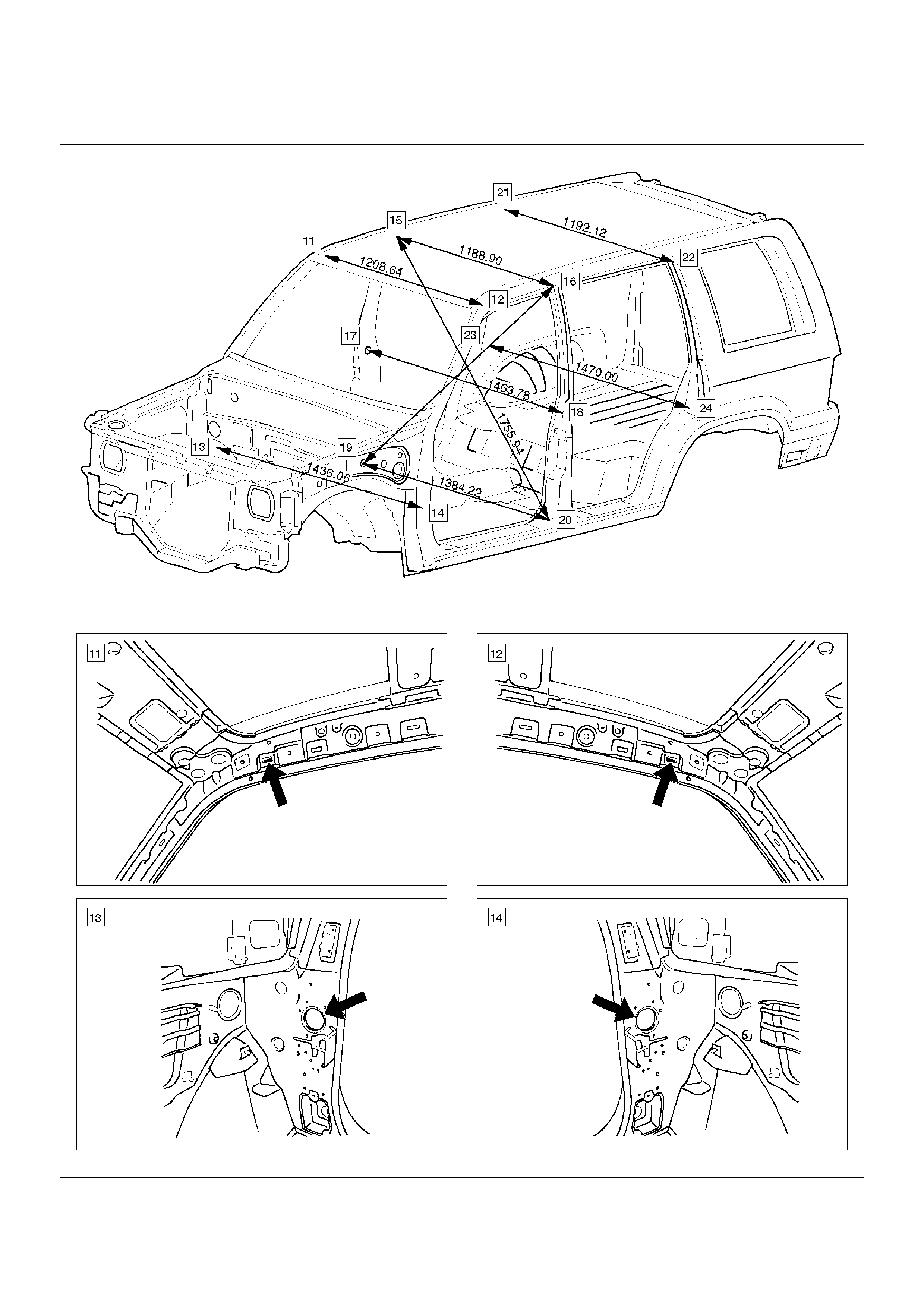
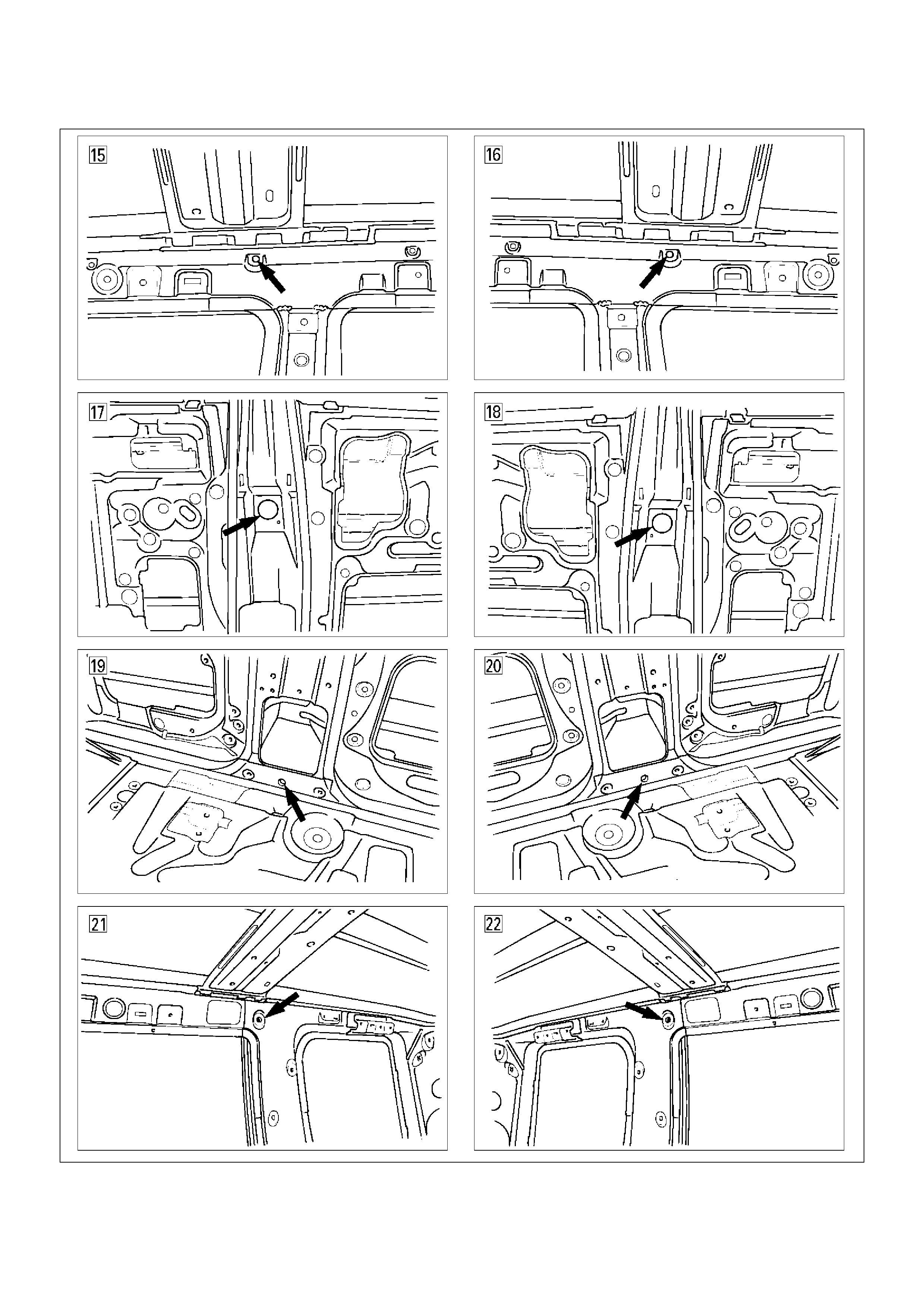
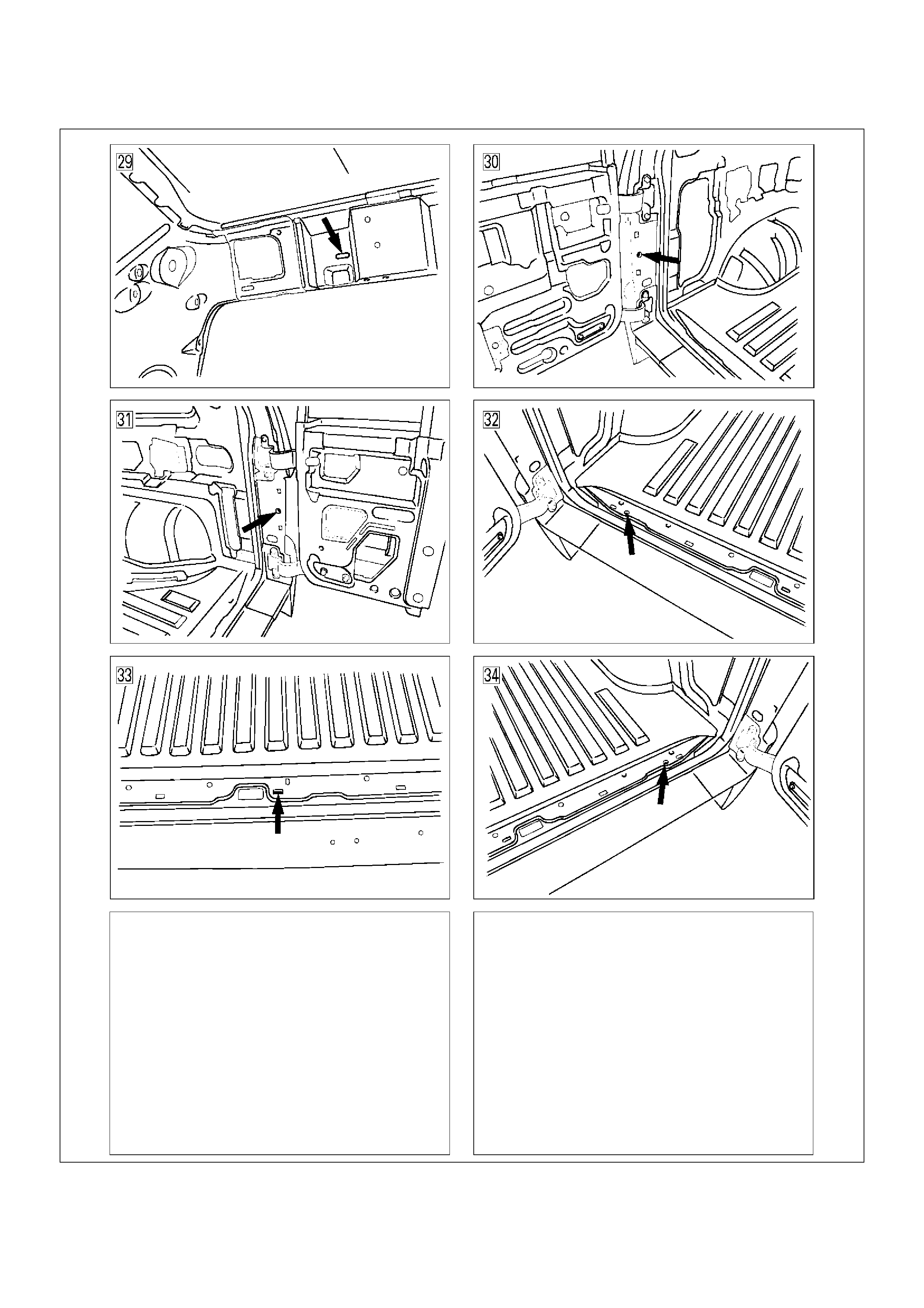
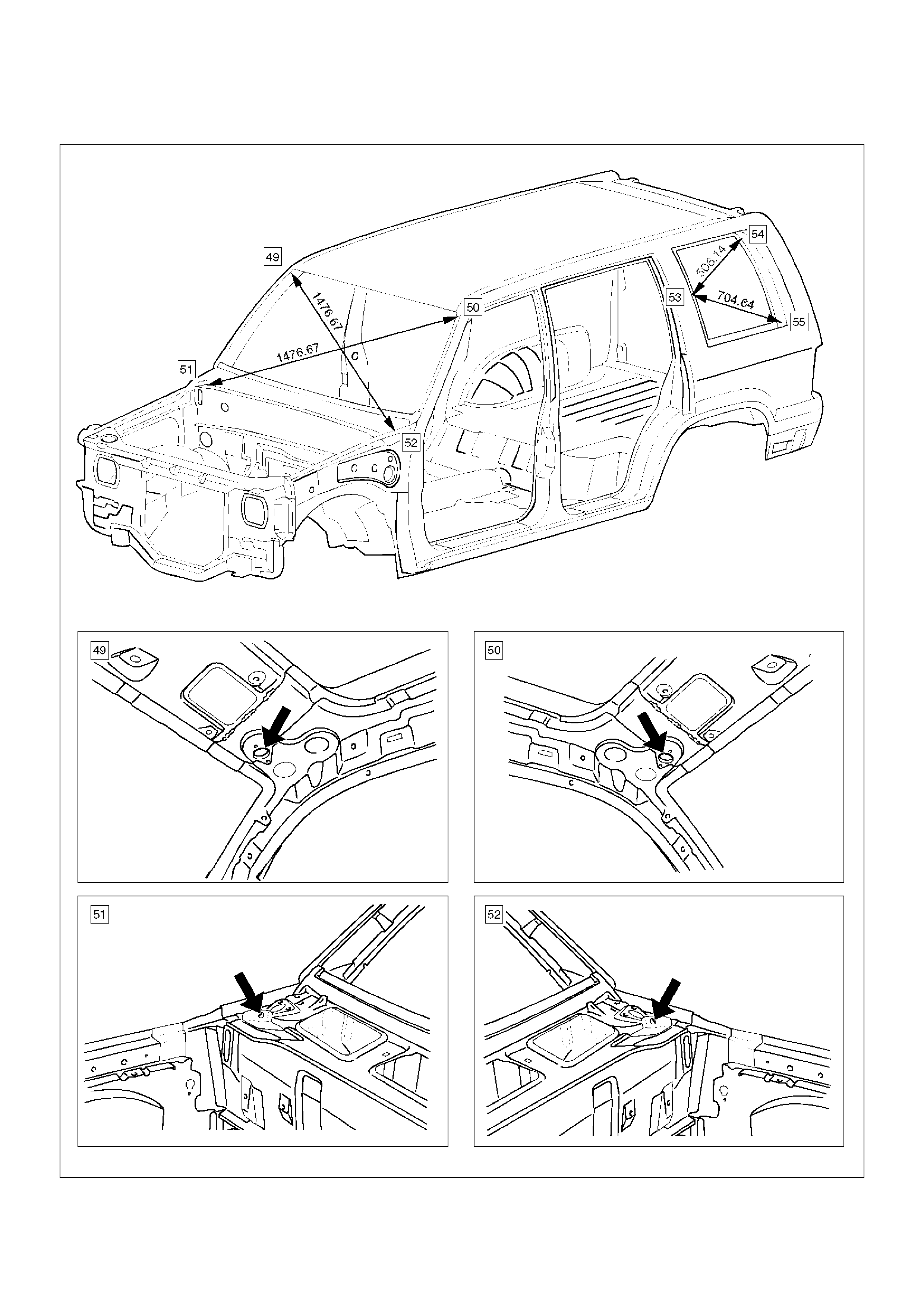
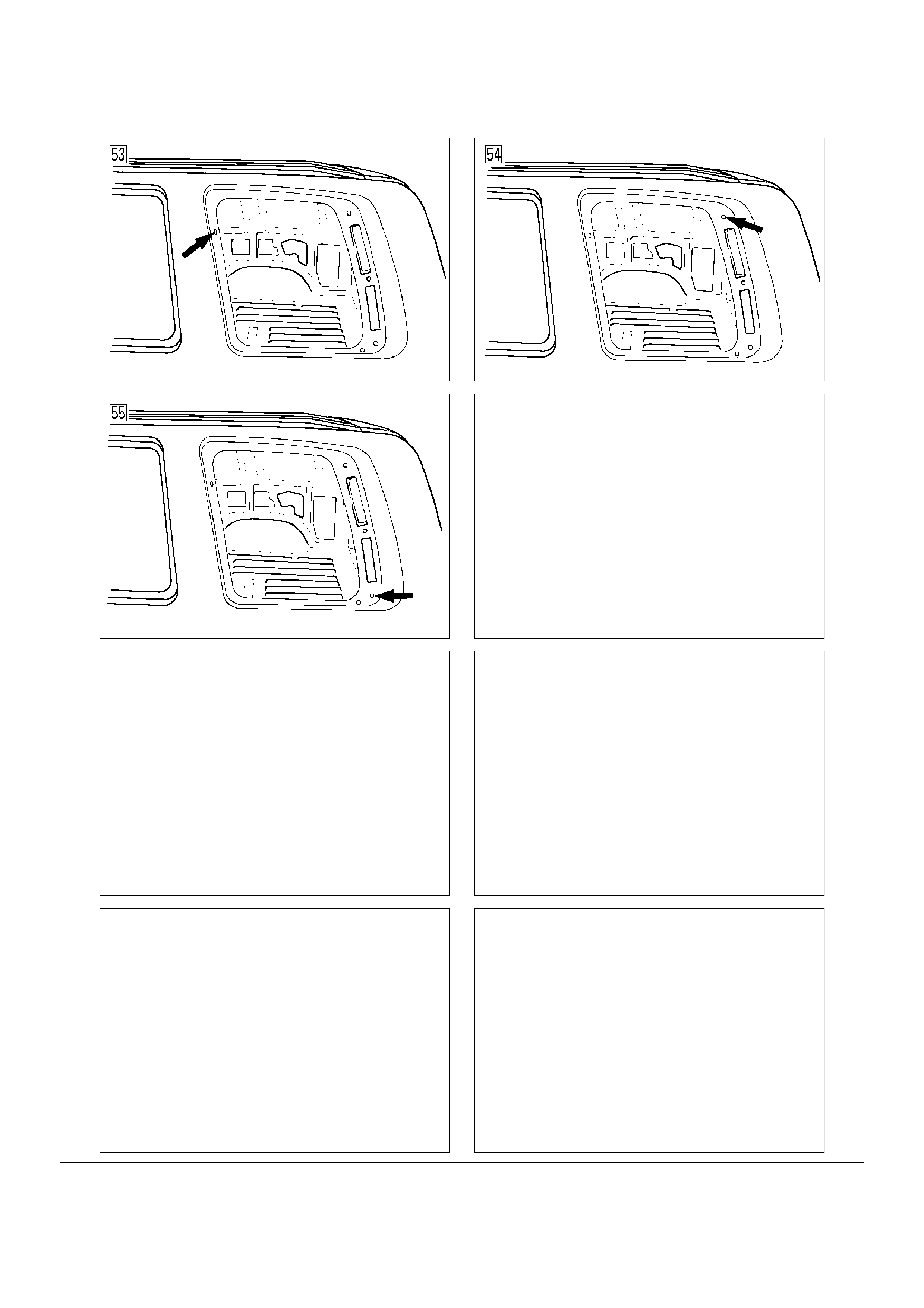
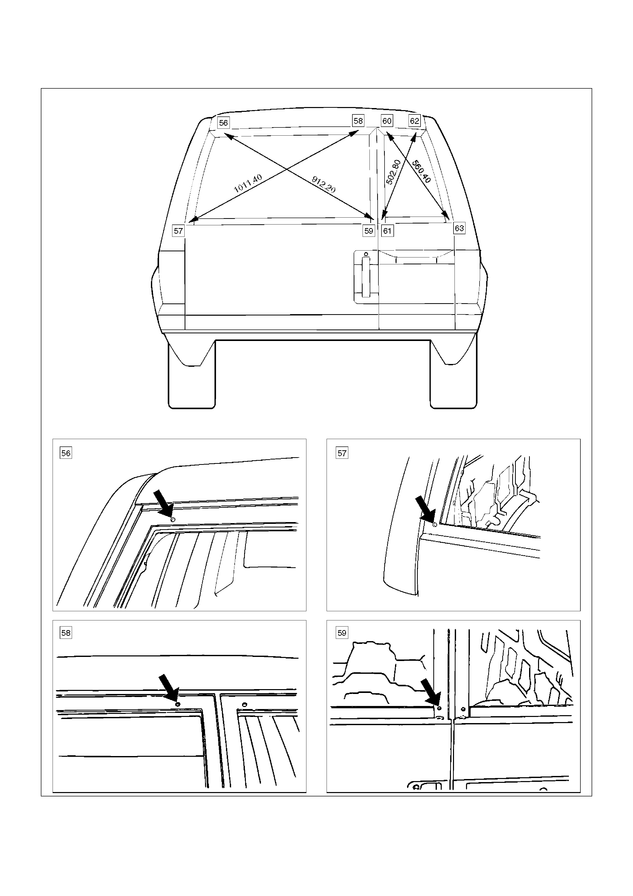
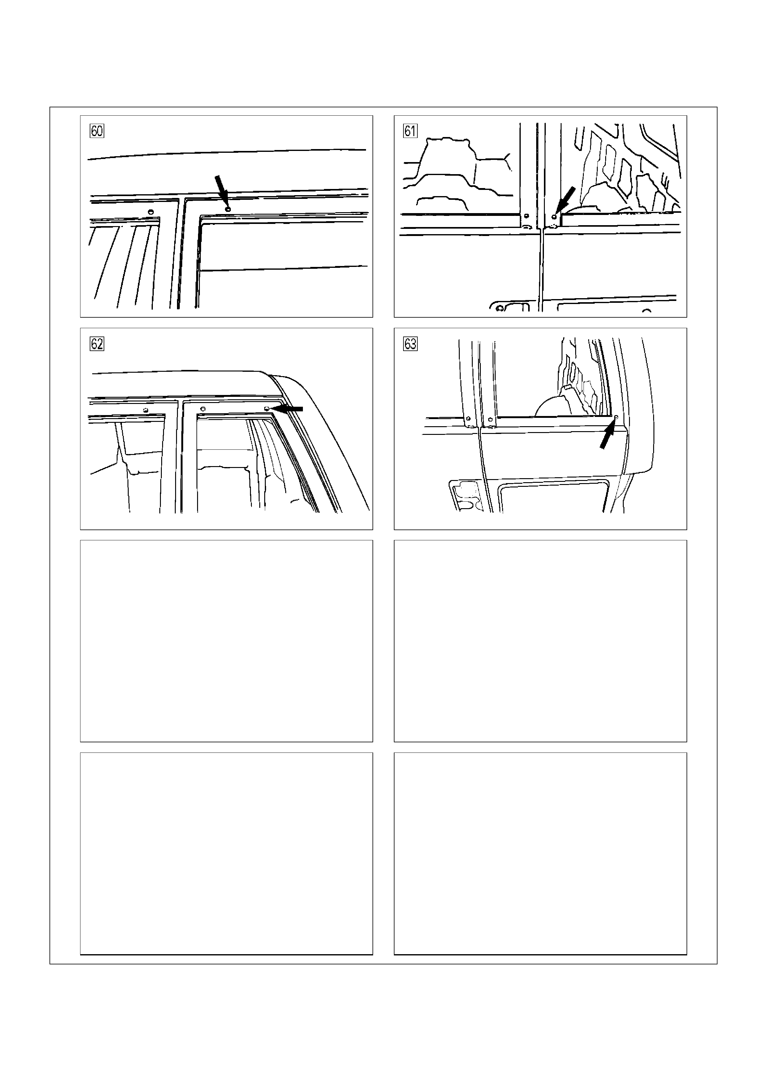
Body Dimension
Upper Body
A10RW001
A10RY00001
A10RY00002
A10RY00007
Front Section
A10RW031
A10RW004
Room Section (LWB)
A10RW030
A10RW005
A10RW006
A10RW024
A10RW025
Rear Section
A10RW032
A10RW008
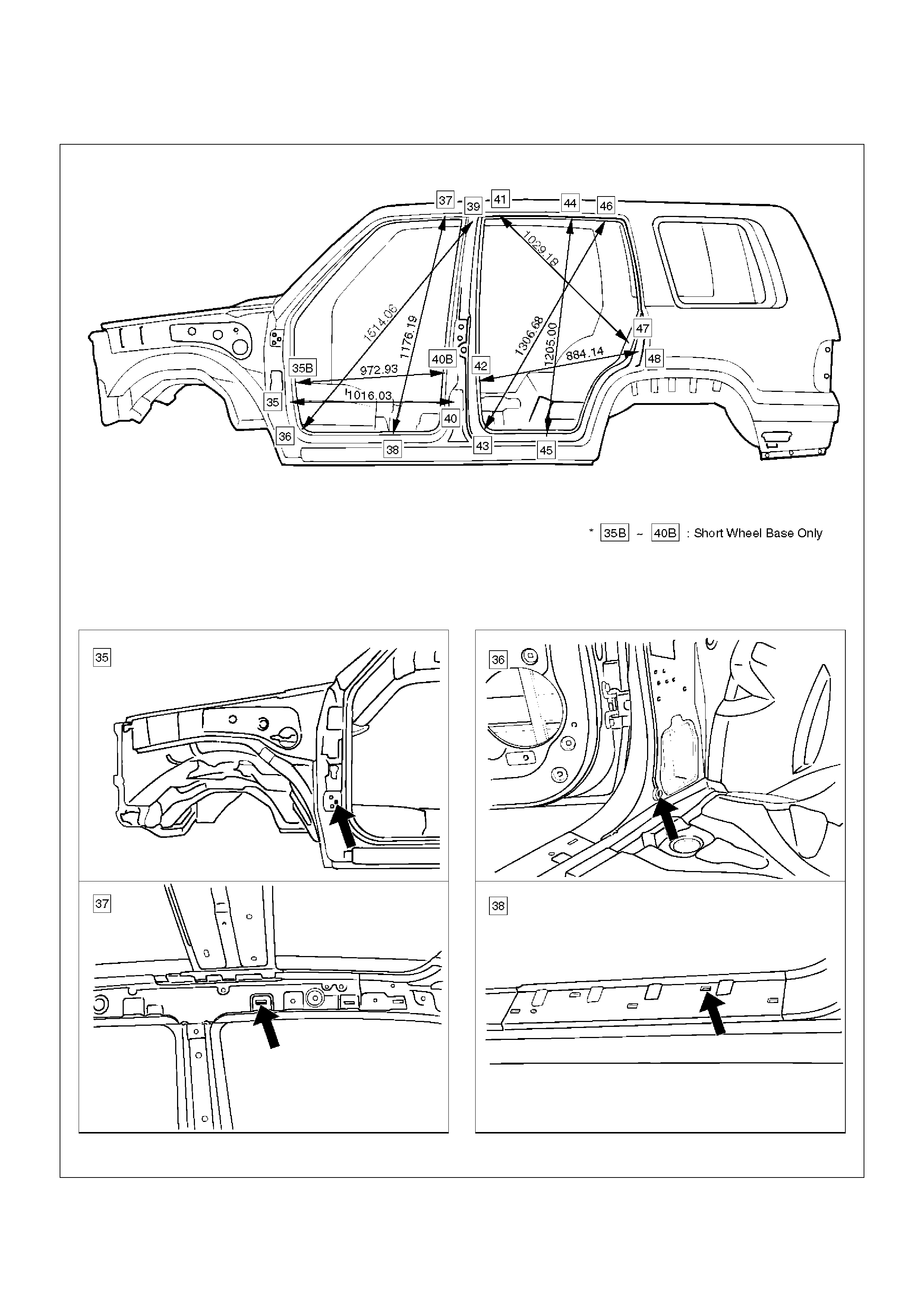
Side Body
A10RW026
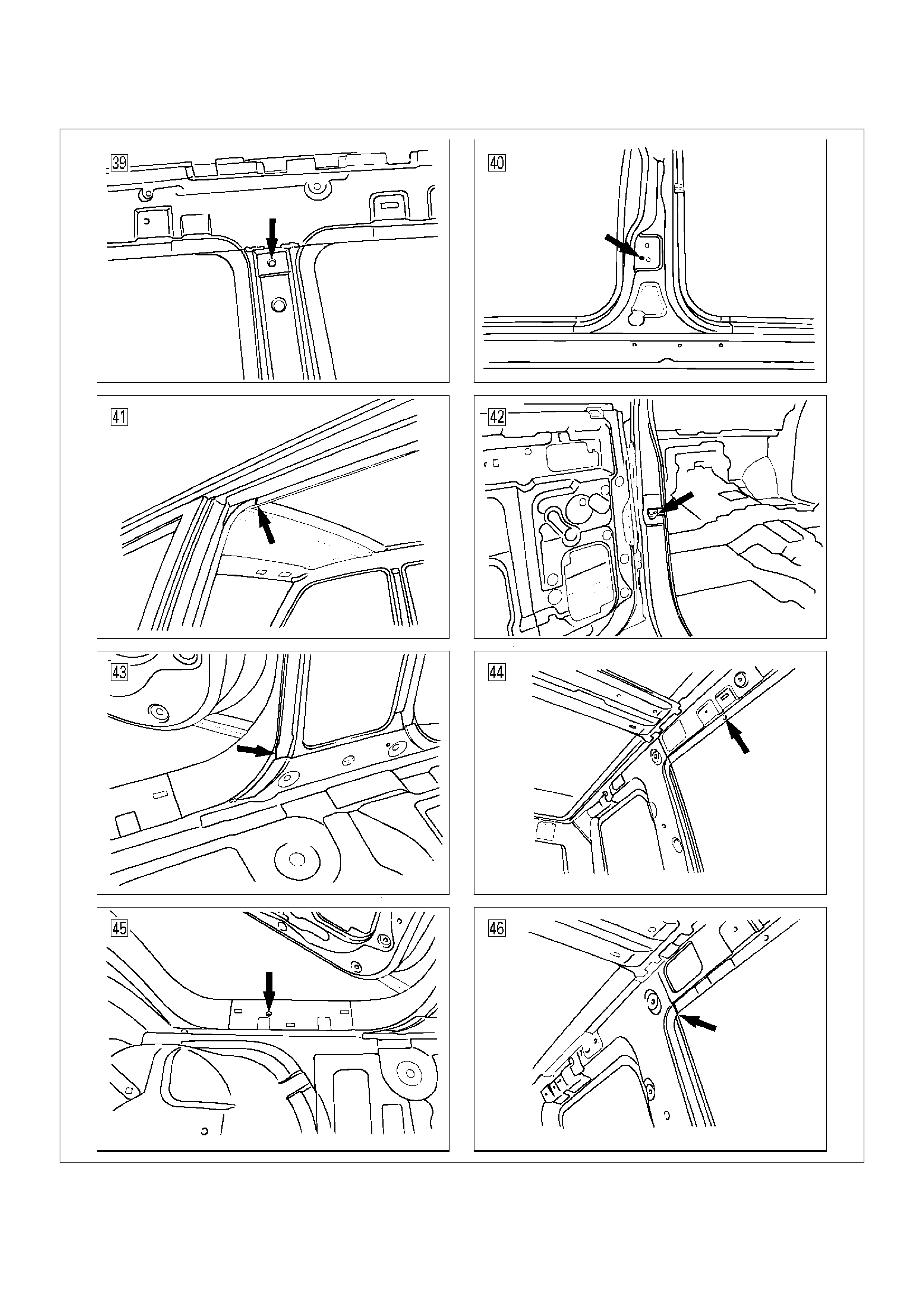
A10RW009
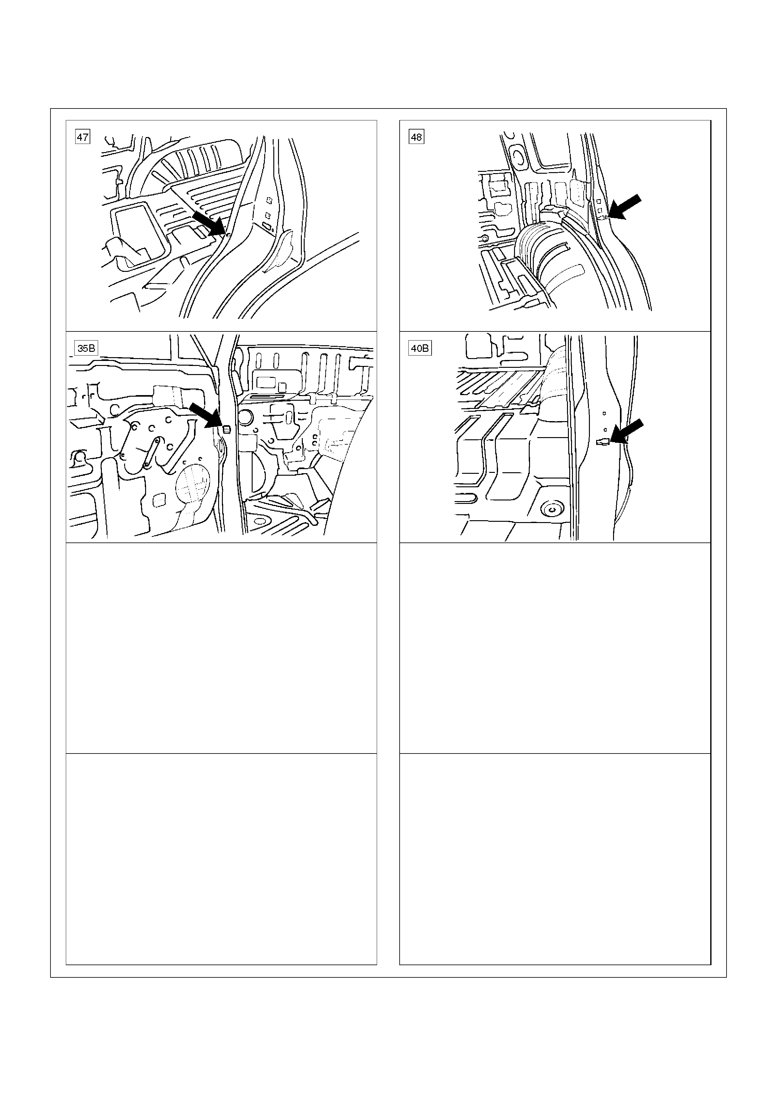
A10RW027
Window Glass
A10RW028
A10RW011
A10RW029
A10RW013
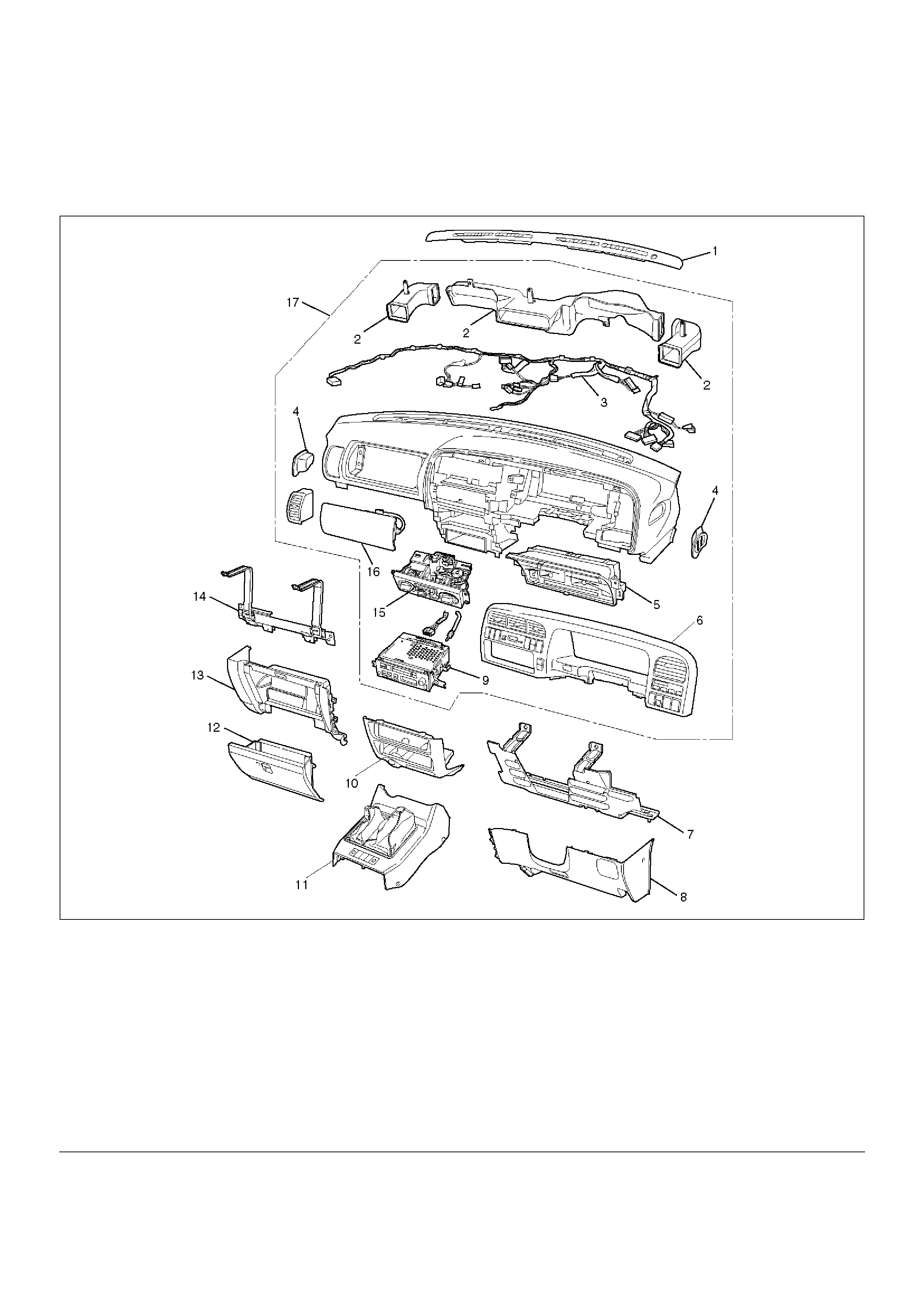
Instrument Panel Assembly
Parts Location
740RY00028
EndOFCallout
Legend
(1) Front Defroster Grille
(2) Vent Duct Assembly
(3) Instrument Harness Assembly
(4) Side Defroster Grille
(5) Meter Assembly
(6) Instrument Panel Cluster Assembly
(7) Driver Knee Bolster Assembly (W/SRS)
(8) Instrument Panel Driver Lower Cover Assembly
(9) Radio Assembly
(10) Lower Cluster Assembly
(11) Front Console Assembly
(12) Glove Box
(13) Instrument Panel Passenger Lower Cover
Assembly
(14) Passenger Knee Bolster Reinforcement
Assembly
(15) Control Lever Assembly
(16) Passenger Inflator Module (W/SRS)
(17) Instrument Panel Assembly
Removal
CAUTION: For precautions on installation or
removal of SRS—air bag system, refer to
Supplemental Restraint System (SRS) — AIR BAG
in Restraint section.
1. Disconnect the battery ground cable.
2. Remove front console assembly.
• Remove the 4 fixing screws and disconnect the
switch connectors.
3. Remove lower cluster assembly.
• Remove the 3 fixing screws (1) in order to
disconnect the cigarette lighter (3) and the
illumination (2) connectors.
740RS014
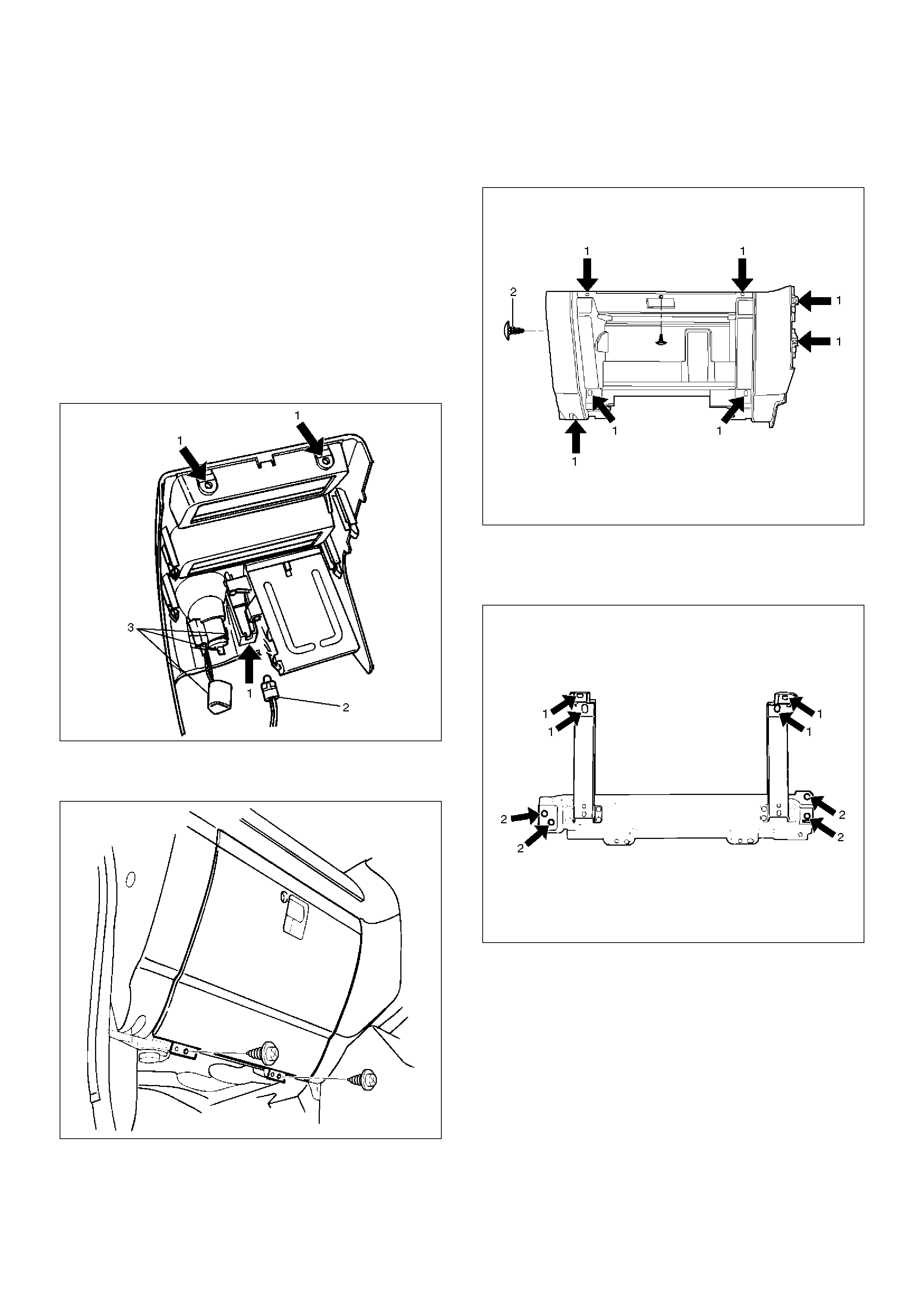
4. Remove glove box.
• Remove the 2 fixing screws.
740RW104
5. Remove instrument panel passenger lower cover
assembly.
• Remove the 7 fixing screws (1) and 1 clip (2).
740RW103
6. Remove passenger knee bolster reinforcement
assembly.
• Remove the 4 fixing bolts (2) and 4 nuts (1).
740RS011
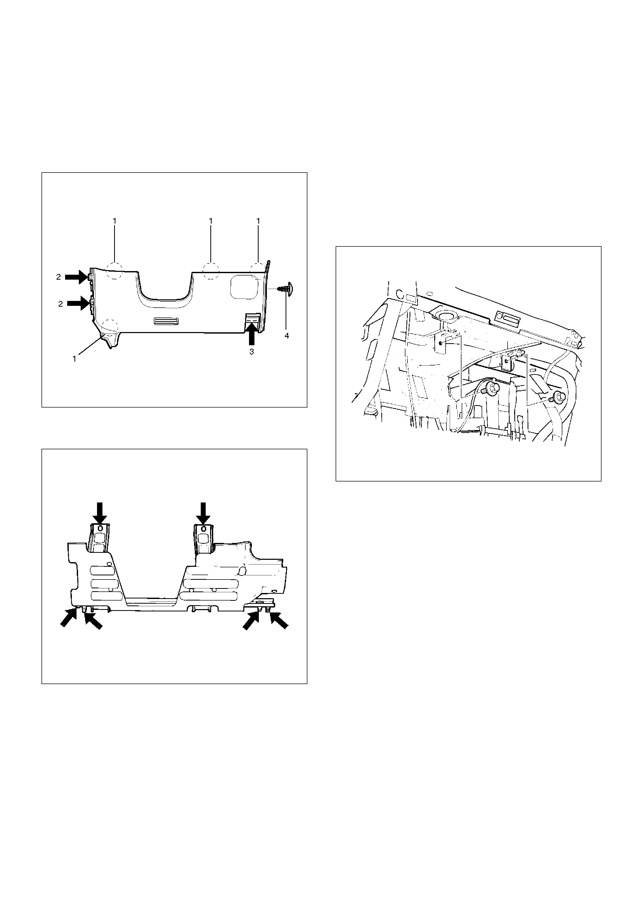
7.Remove instrument panel driver lower cover
assembly.
•Remove the engine hood opener fixing screws.
•Remove the 2 fixing screws (2), 1 fixing bolt (3),
and 1 clip (4). Pull out the fasteners at the 4
positions (1).
740RW105
8.Remove driver knee bolster assembly (W/SRS).
•Remove the 6 fixing nuts.
740RW122
9.Remove front defroster grille.
•Pry 8 claws on the front side toward you side
(room side) and raise the grille upward.
10.Remove instrument panel assembly.
•Remove the 2 fixing bolts on the SRS adjust
bracket and the cross beam under the passenger
inflator module (W/SRS).
CAUTION: For precautions on installation or
removal of SRS — air bag system, refer to
Supplemental Restraint System (SRS) — AIR BAG
in Restraint section.
827RW031
• Disconnect the 3 air conditioner control cables on
the unit side.
• Remove the instrument harness connectors (5
connectors on the drivers side and 3 connectors
on the passenger side), the passenger inflator
module connector, the radio antenna cable plug,
and the ground cable fixing bolt on the center
bracket.
• Remove the 4 bolts (4) and the 2 nuts (3) under
the instrument panel assembly, and the upper left
and the upper right bolts (2) and the center nut
(1).
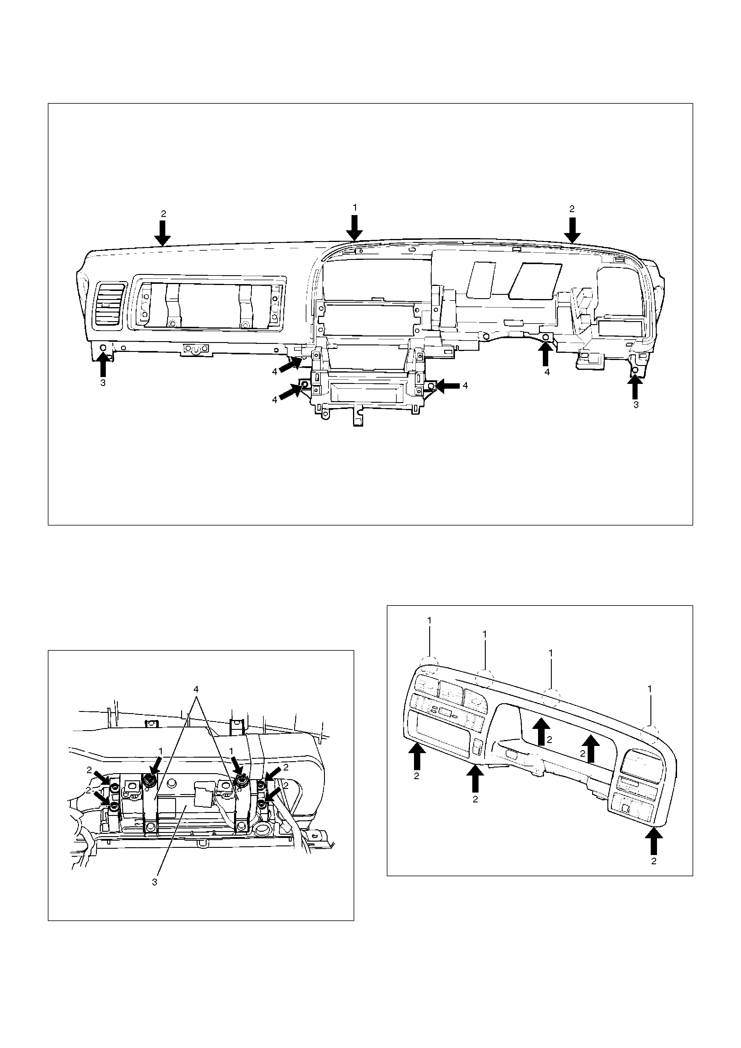
740RW106
11. Remove passenger inflator module (W/SRS).
• From the back of the instrument panel, remove
the 4 fixing nuts (2) on the passenger inflator
module (3) and the 2 fixing nuts (1) and washers
on the support bracket (4), then disengage the 2
clips in order to remove the passenger inflator
module.
827RW032
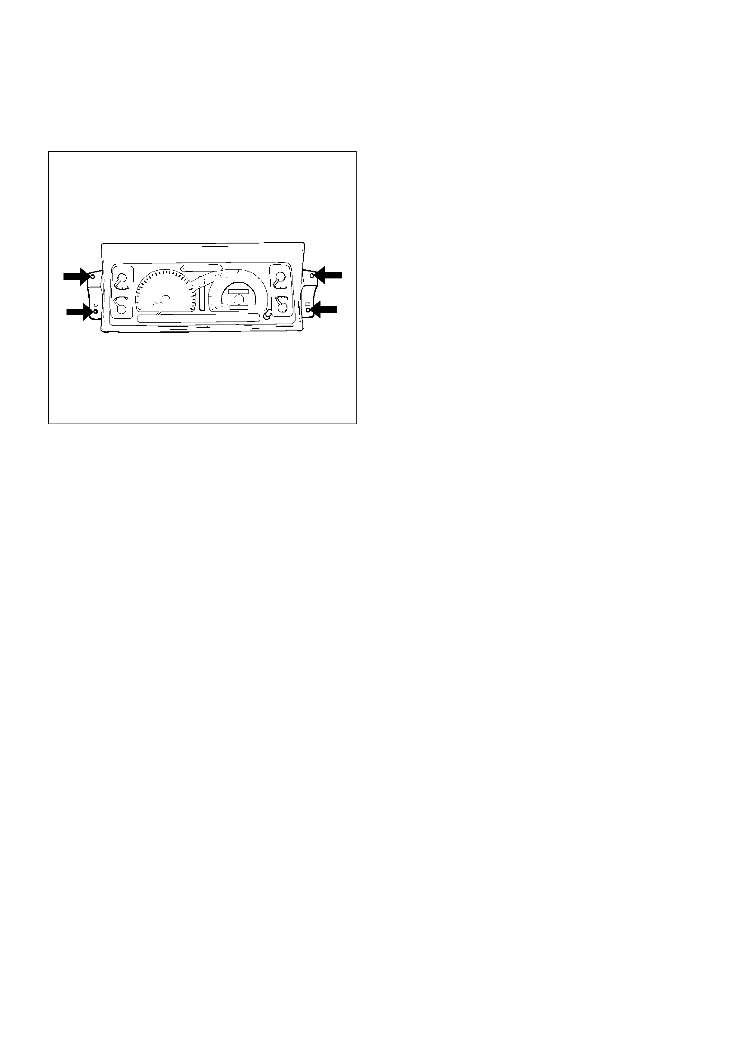
12. Remove instrument panel cluster assembly.
• Remove the 5 fixing screws (2) and pull the main
unit toward you and remove the clips at the 4
positions (1). Disconnect the switch connectors.
740RW107
13.Remove meter assembly.
•Remove the 4 meter assembly fixing screws and
disconnect the meter harness connectors.
821RS034
14.Remove control lever assembly.
•Refer to Control Lever Assembly And/Or Control
Cables in Heating And Ventilation section.
15. Remove radio assembly.
• Remove 2 fixing screws.
16. Remove vent duct assembly.
• Remove 5 fixing screws.
17. Remove instrument harness assembly.
• Remove the 4 fixing screws, fasteners at the 4
positions and the clips at the 7 positions.
18. Remove side defroster grille.
NOTE: For the order of removal steps in which each
items contained in the instrument panel assembly are
removed individually, refer to the chart.

Installation
To install, follow the removal steps in the reverse order.
Order Of Removal/Installation Steps For Each Item
M/T = Manual Transmission
A/T = Automatic Transmission
SRS = Supplemental Restraint System
A/C = Air Conditioning
Removal Item Removal Procedure Removal Step
Front console assembly Shift knob (M/T), Power & Winter SW (A/T), Transfer knob, Seat
heater/Miller SW conn. and 4 screws
1, 2
Lower cluster assembly 3 screws, Ciger lighter conn. and Ashtray illumination conn. 1~3
Glove box 2 screws 4
Instrument panel
passenger lower cover
7 screws and 1 clip 1~5
Passenger knee bolster
reinforcement
4 nuts and 4 bolts 1~6
Instrument panel driver
lower cover
Engine hood opening fixing screw, 2 screws, 1 bolt, 1 clip and
fasteners at 4 positions
1~3, 7
Driver knee bolster 6 nuts 1~3, 7, 8
Front defroster grille Claws at 8 positions 9
Instrument panel
assembly
2 bolts (SRS adjust bracket~ cross beam), A/C control cable (Unit side
at 3 position), Instrument harness connector (Driver side 5 position,
assist side 3 position), SRS module conn., Radio antenna jack, Earth
cable, 9 bolts and 3 nuts
1~10
Passenger inflator
module
4 nuts (SRS module~Instrument panel), 2 nuts 0 and 2 washers (SRS
module~support bracket) and 2 clips
1~6, 11
Instrument panel
cluster
5 Screws, fastener at 4 position and each SW conn. 1~3, 7, 12
Meter assembly 4 screws and connectors 1~3, 7, 12, 13
A/C control panel
assembly
4 screws and connectors 1~3, 7, 12, 14
Radio assembly 2 screws 1~3, 15
Vent duct assembly 5 screws 1~10, 16
Instrument harness
assembly
4 screws, fasteners at 4 position, and clips at 7 position 1~10, 17
Side defroster grille 18
Cross Beam Assembly
Parts Location
740RW100
EndOFCallout
Removal
1.Disconnect battery ground cable.
2.Remove instrument panel assembly.
•Refer to Instrument Panel Assembly in this
section.
3.Remove side support bracket assembly (LH/RH).
•Remove the 4 fixing bolts on both sides.
4.Remove cross beam center bracket
•Remove 2 fixing nuts.
5.Remove instrument panel center bracket.
•Disconnect the PCM and EBCM connector.
•Remove the DERM (SRS) with 3 fixing nuts.
CAUTION: For precautions on installation or
removal of SRS — air bag system, refer to
Supplemental Restraint System (SRS) — AIR BAG
in Restraint section.
• Remove the 2 fixing nuts (upper) and the 4 fixing
bolts (lower).
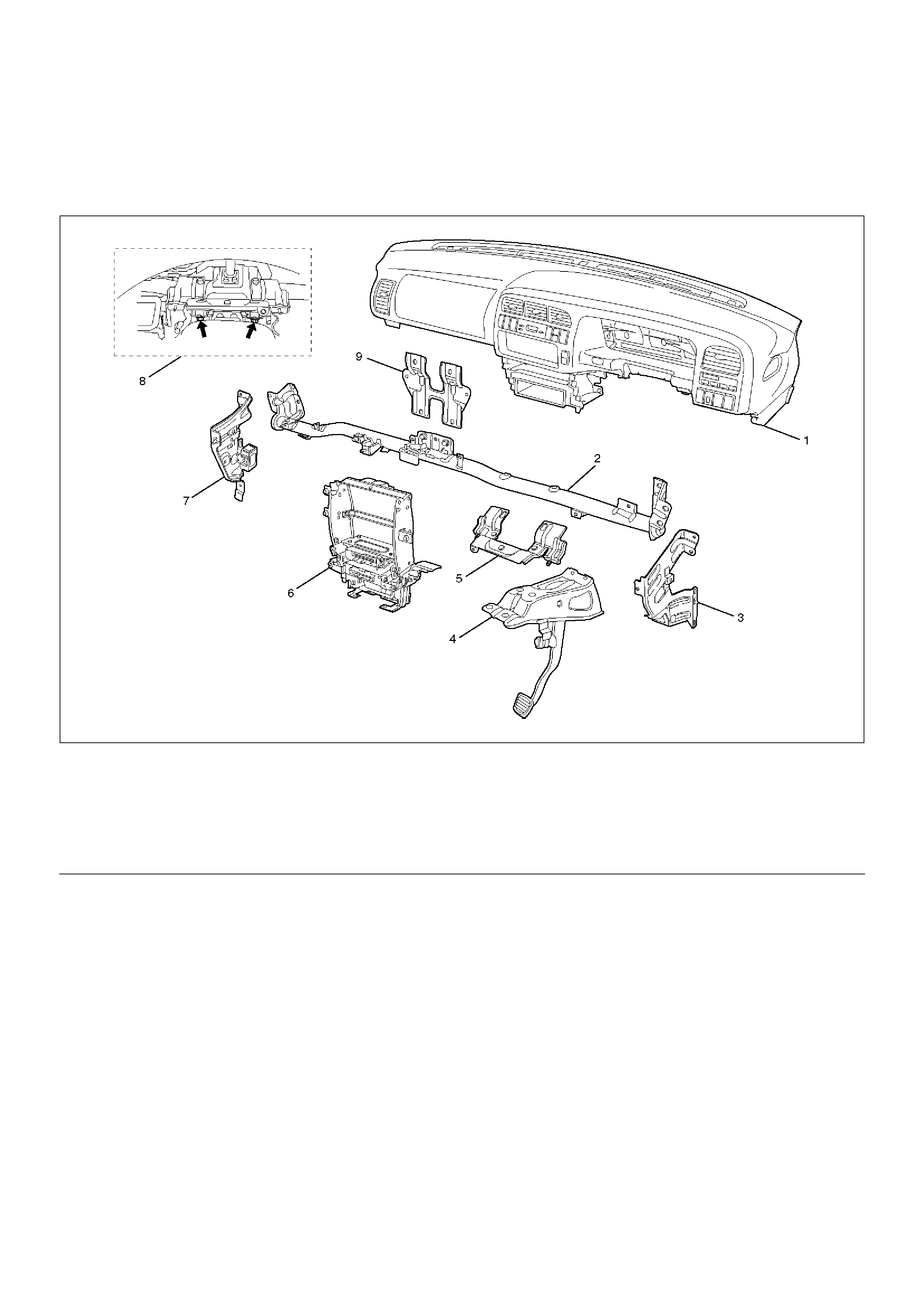
Legend
(1) Instrument Panel Assembly
(2) Cross Beam Assembly
(3) Side Support Bracket Assembly (RH)
(4) Brake Pedal Mounting Bracket Assembly
(5) Steering Support Bracket Assembly
(6) Instrument Panel Center Bracket
(7) Side Support Bracket Assembly (LH)
(8) Steering Column Fixing Bolts
(9) Cross Beam Center Bracket
740RW101
6. Remove steering column fixing bolts.
• Remove 2 fixing bolts.
431RW007
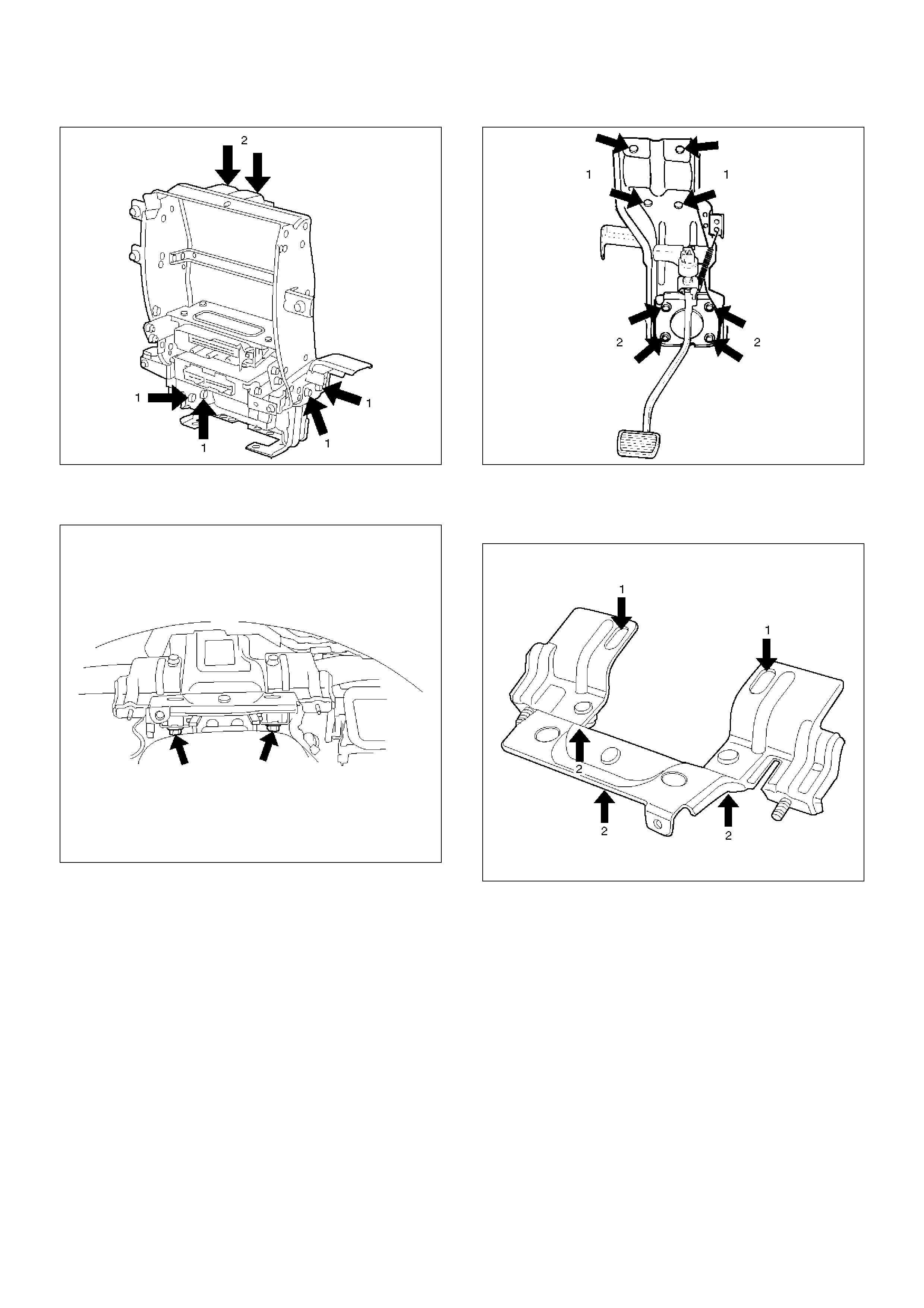
7. Remove brake pedal mounting bracket assembly.
• Disconnect the 2 brake pedal mounting bracket
assembly fixing nuts, and remove the antitheft
controller.
• Disconnect the brake pedal link and the brake
switch, and remove the 4 fixing bolts and the nuts
on the bracket.
310RW014
8. Remove steering support bracket assembly.
• Remove the 2 fixing bolts (upper side) (1) and the
3 fixing nuts (lower side) (2).
740RW102
9. Remove cross beam assembly.
• Disconnect the harness clips from the crossbeam
assembly, and remove 2 fixing bolts on both sides
and 2 fixing nuts in the center.
Installation
To install, follow the removal steps in the reverse order.
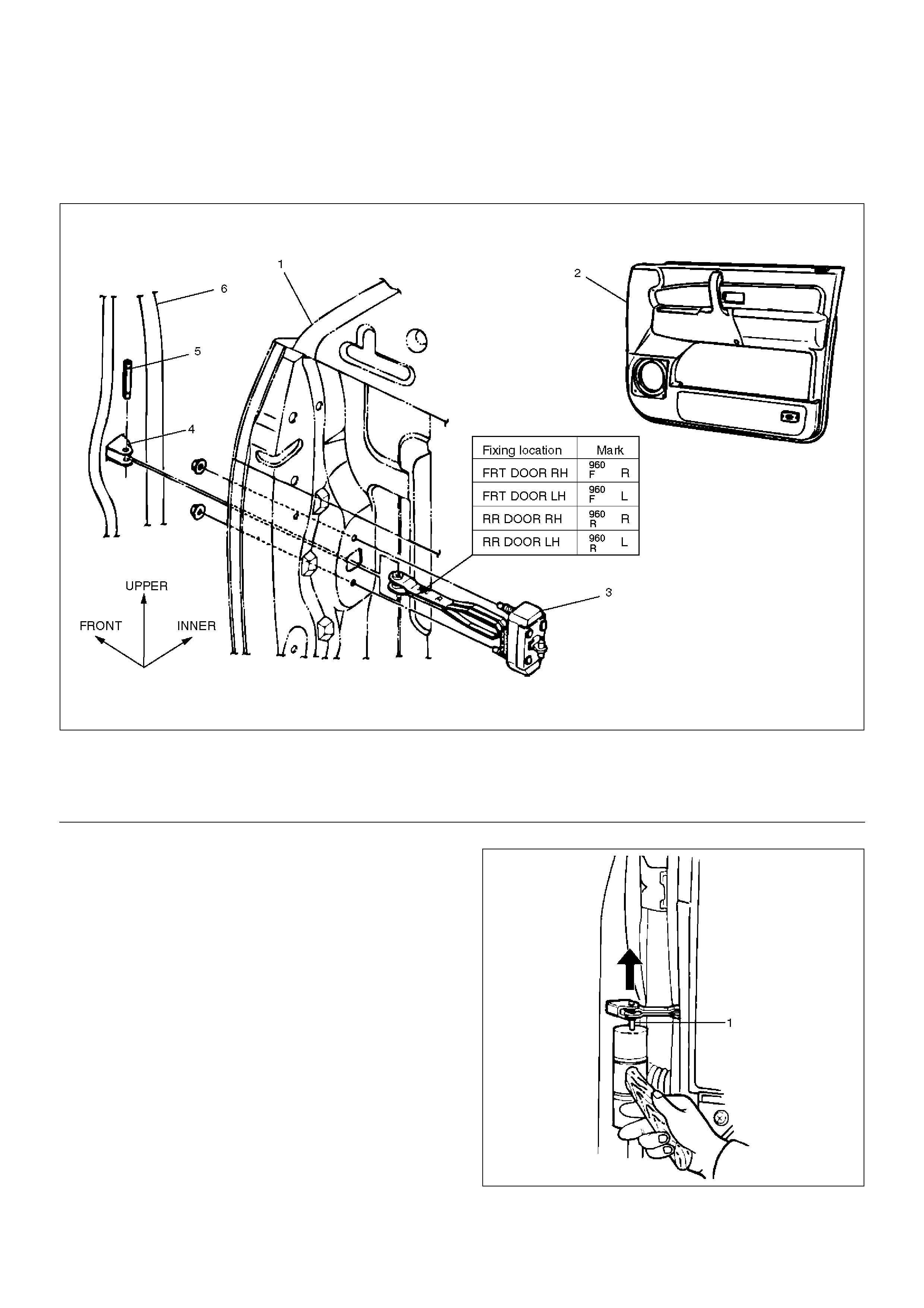
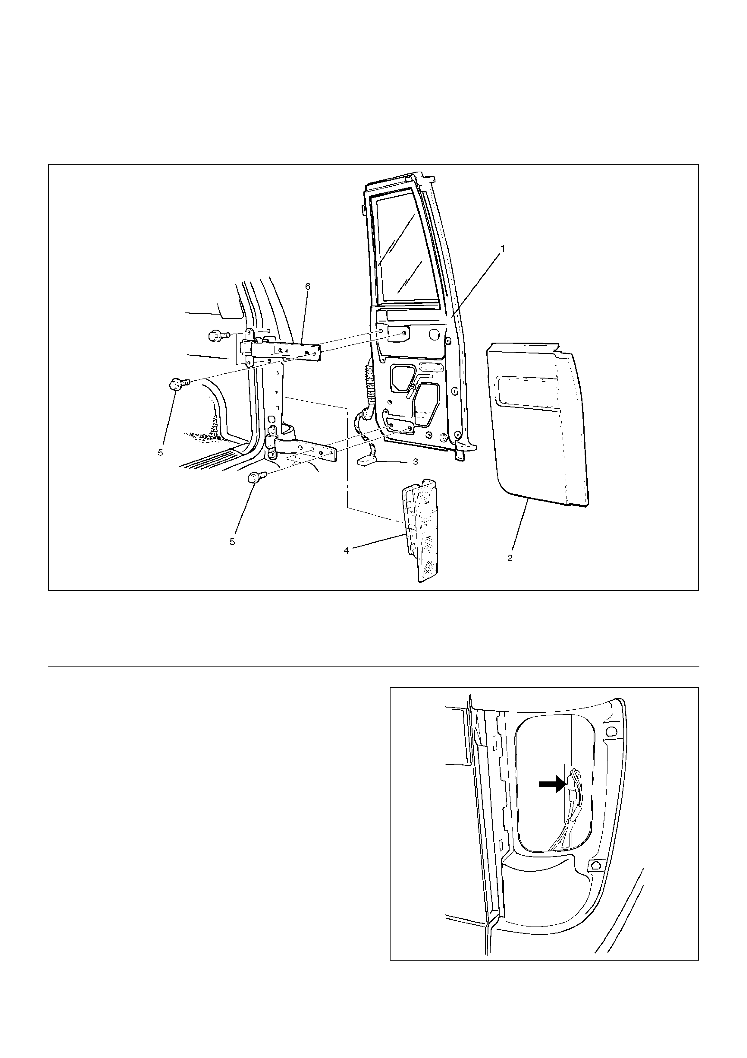
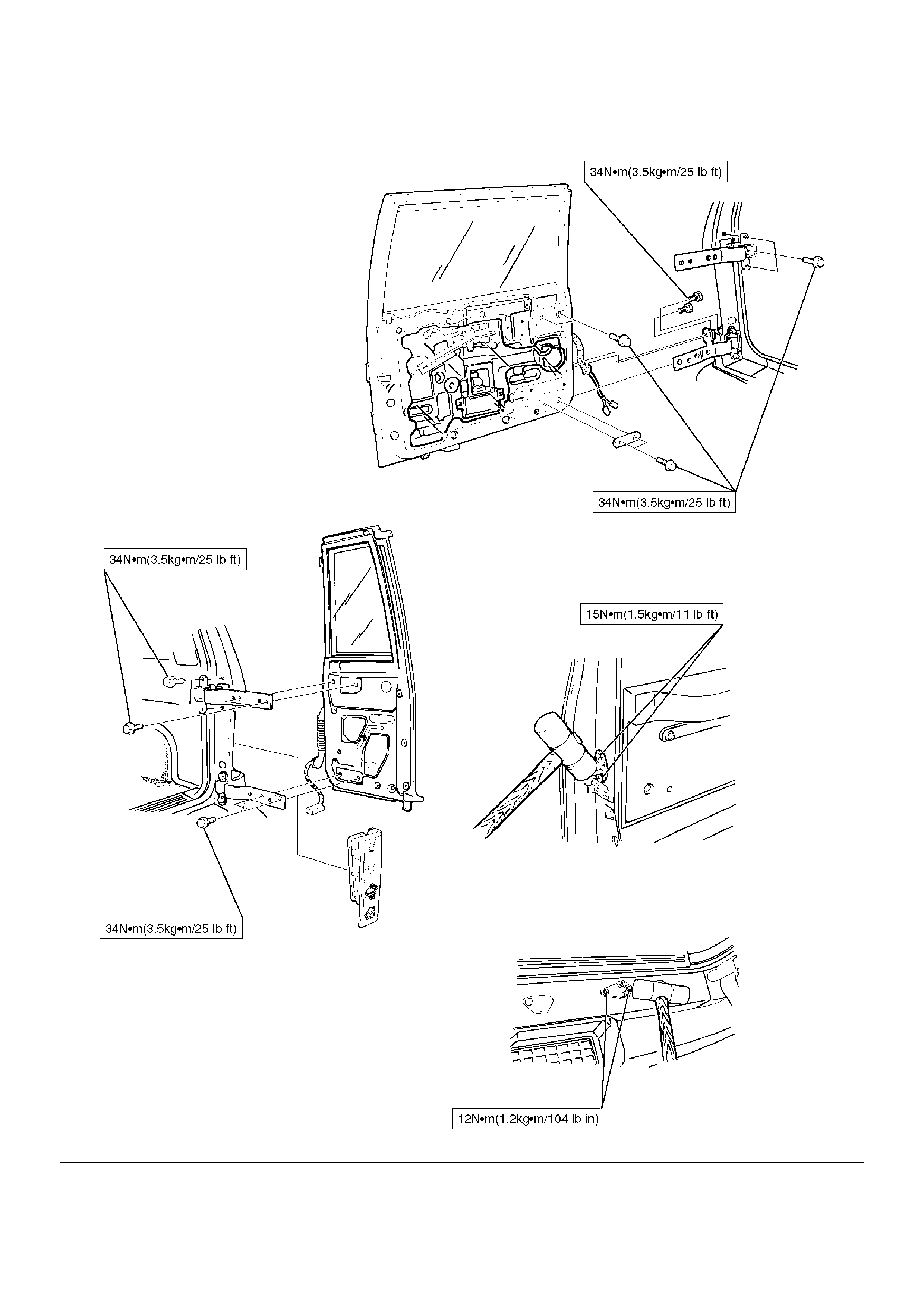
Front Door Assembly
Parts Location
630RS001
EndOFCallout
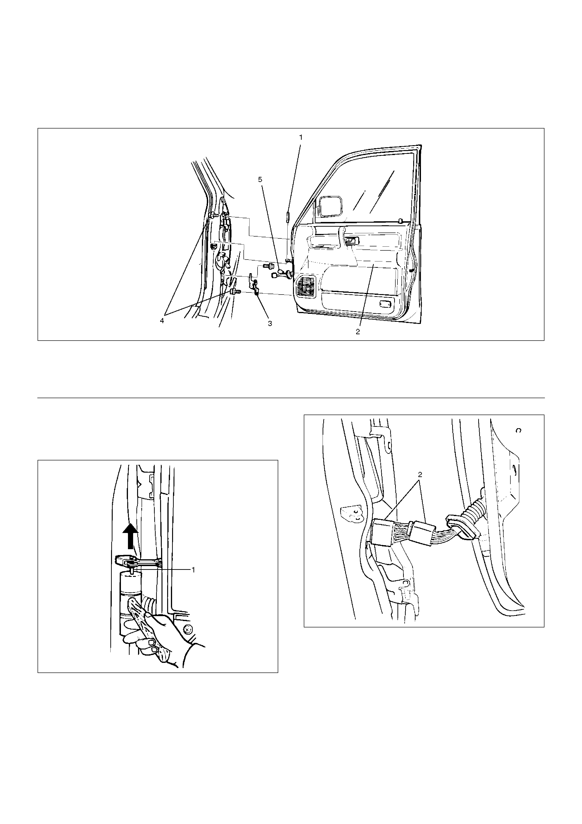
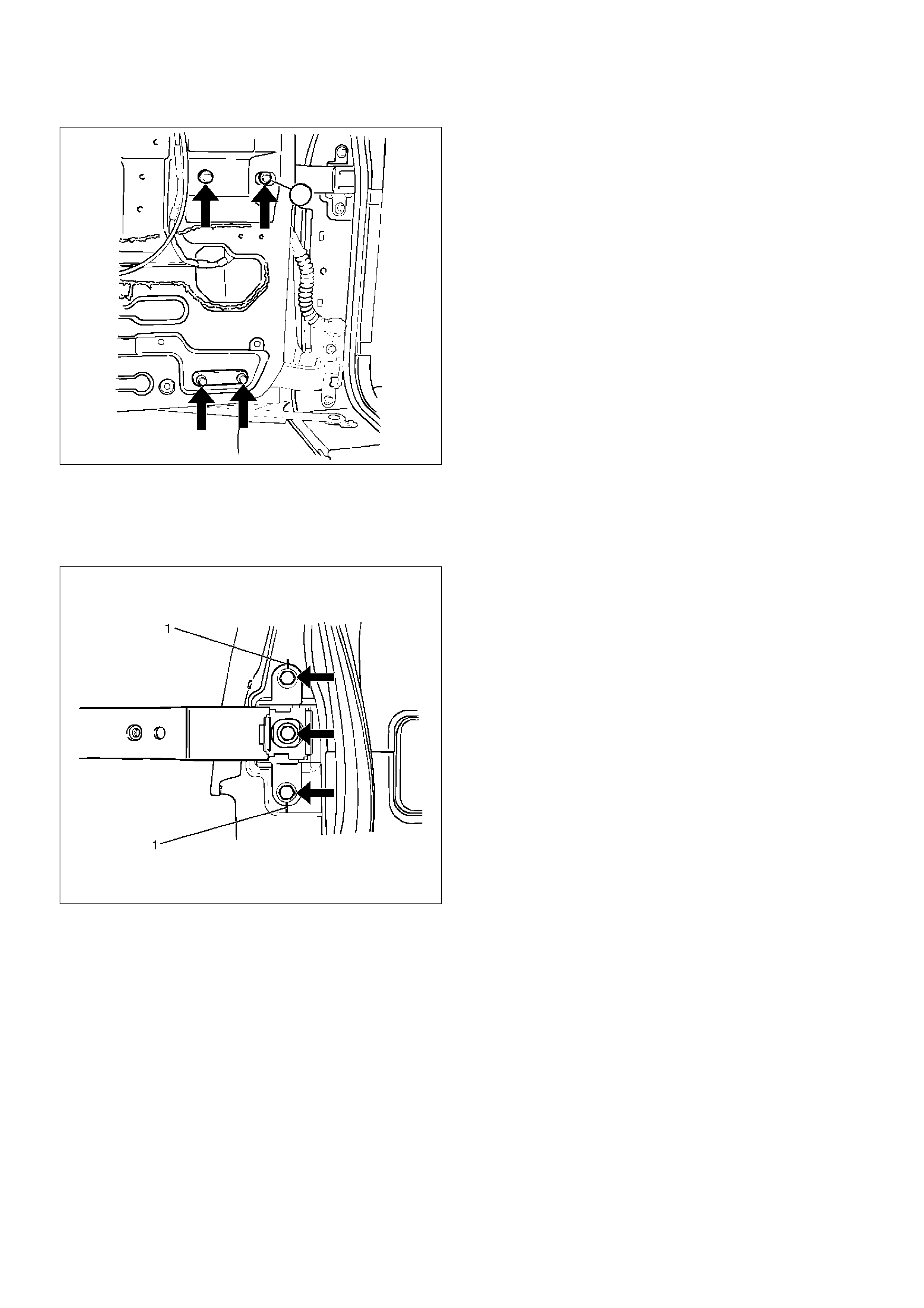
Removal
1.Disconnect the battery ground cable.
2.Remove door check arm pin (1).
630RS002
3.Remove hinge bolt.
•Align the hinge bolt to the door side hinge and put
a marker on it.
4.Remove door harness connection (2).
•Pull the door harness grommet out in order to
disconnect the harness connection.
810RS001
5.Remove front door assembly.
Installation
To install, follow the removal steps in the reverse order,
noting the following points:
1.Align the door fitting to the body by referring to Body
Dimensions in this section.
2. Tighten the door hinge bolts to the specified torque.
Torque : 34 N•m (3.5kg·m/25 lbft)
3. Apply chassis grease to the door check arm pin and
the door hinge moving surface.
Legend
(1) Door Check Arm Pin
(2) Front Door Assembly
(3) Door Hinge Assembly
(4) Hinge Bolt
(5) Door Harness Connection
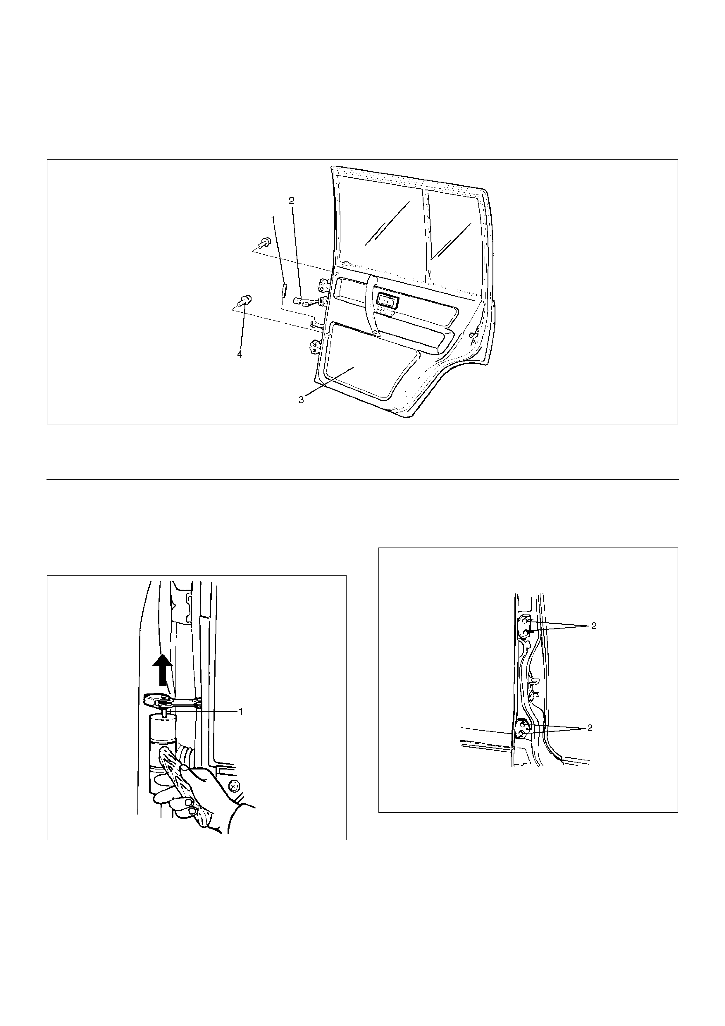
Rear Door Assembly
Parts Location
650RW007
EndOFCallout
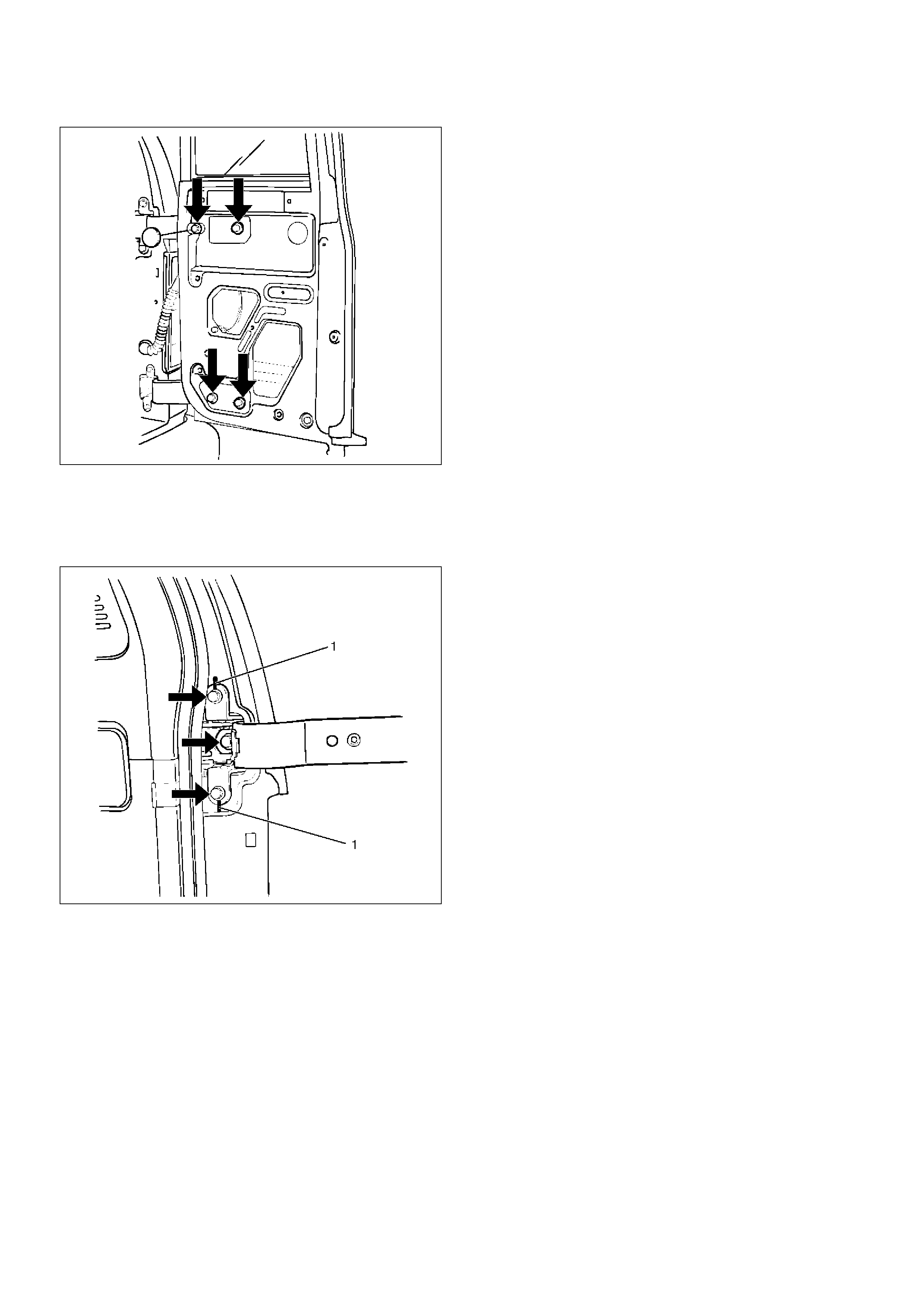
Removal
1. Disconnect the battery ground cable.
2. Apply a setting mark on the body side hinge.
3. Remove door check arm pin (1).
630RS002
4. Remove hinge bolt.
• Open the front door and remove the body side
hinge bolts (2).
650RS002
Legend
(1) Door Check Arm Pin
(2) Door Harness Connection
(3) Rear Door Assembly
(4) Hinge Bolt
5.Remove door harness connection (3).
•Pull the door harness grommet out in order to
disconnect the door harness connection.
810RS002
6.Remove door assembly
Installation
To install, follow the removal steps in the reverse order,
noting the following points.
1.Align the door fitting to the body by refer to Body
Dimensions in this section.
2. Tighten the door hinge bolts to the specified torque.
Torque : 34 N•m (3.5kg·m/25 lbft)
3. Apply chassis grease to the check arm pin and the
door hinge moving surface.
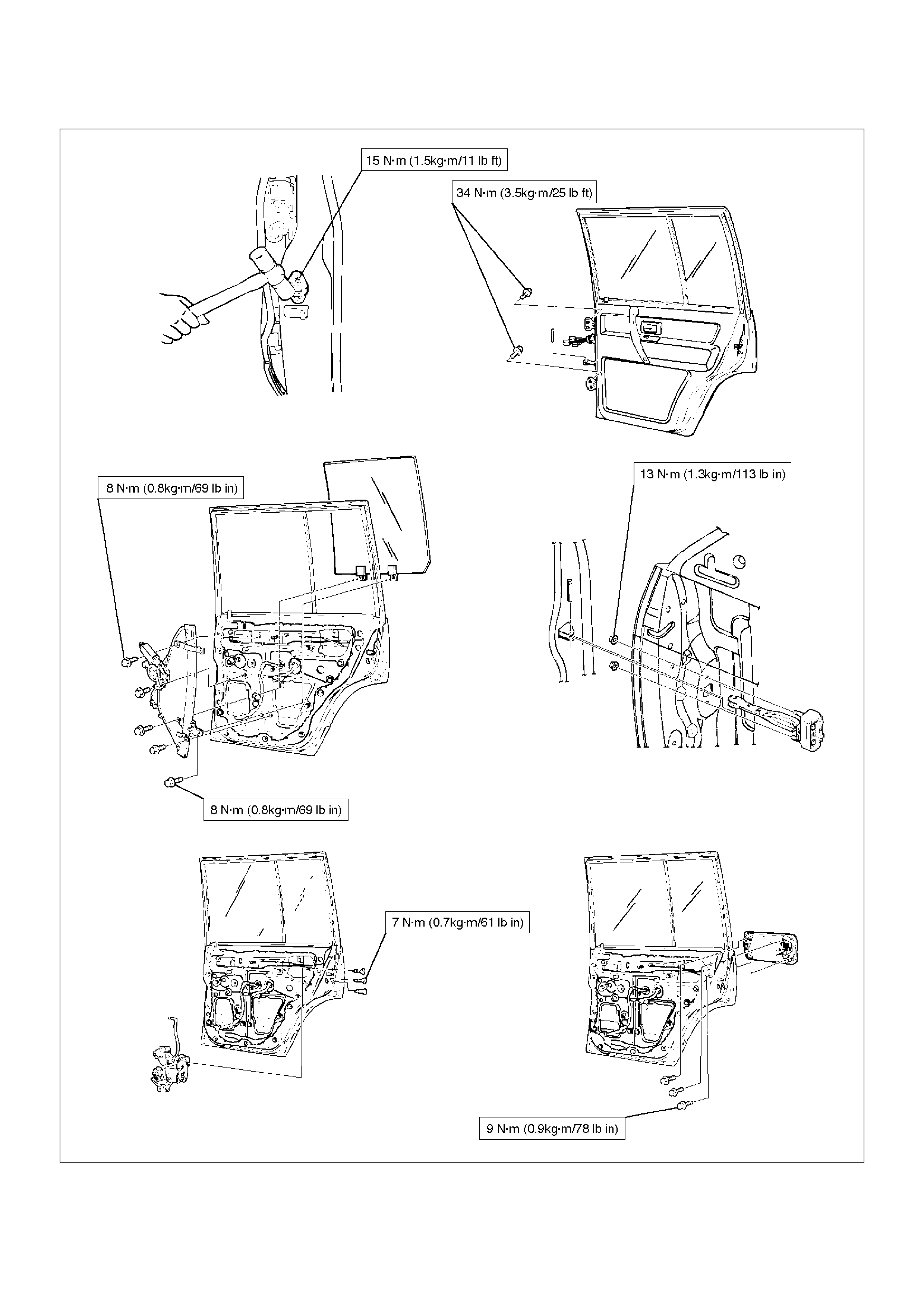
Door Strikers
Adjustment
632RS001
1. Loosen the striker (1) screws.
2. Tap with a plastic hammer to align.
3. Tighten the striker screws.
Torque : 15 N•m (1.5kg·m/11lbft)
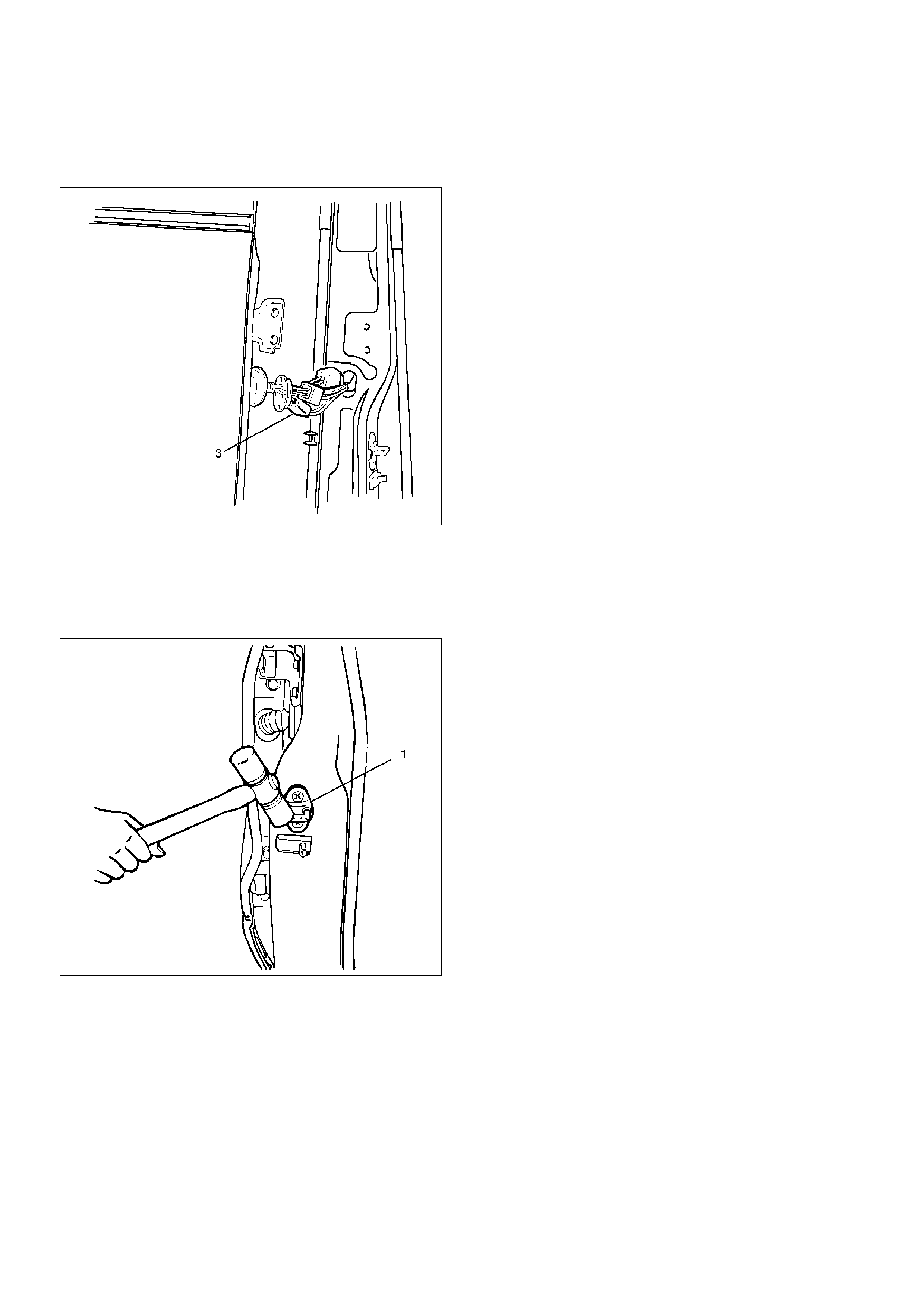
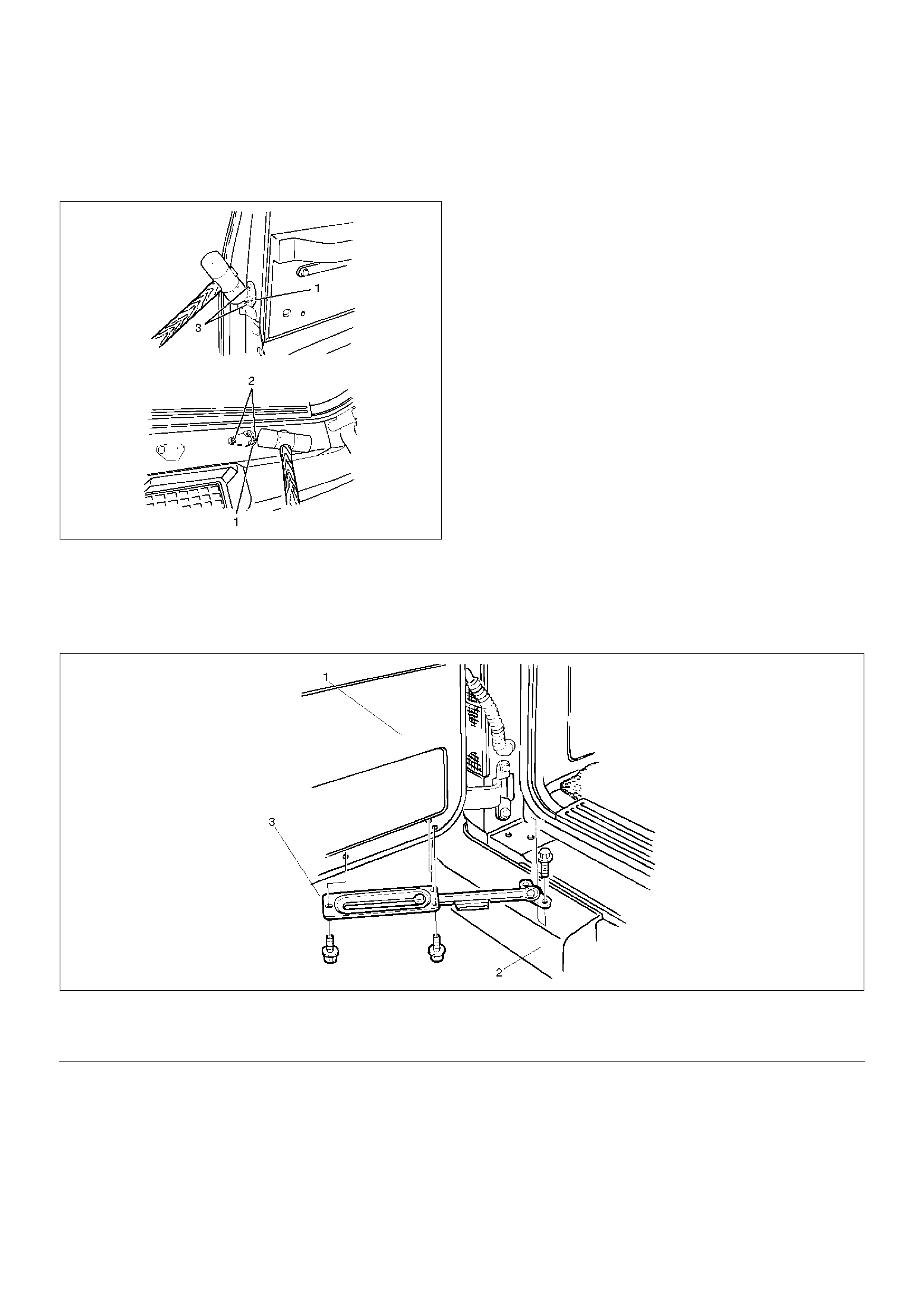
Door Check Arm Assembly (Front & Rear)
Parts Location
630RS003
EndOFCallout
Removal
1.Disconnect the battery ground cable.
2.Remove door trim panel.
•Refer to Front Door Trim Panel in Exterior /
Interior Trim section.
3. Remove check arm pin (1).
630RS002
4. Remove check arm assembly.
Legend
(1) Front or Rear Door
(2) Door Trim Panel
(3) Check Arm Assembly
(4) Check Arm Pin Bracket
(5) Check Arm Pin
(6) Front or Center Pillar
•Carefully peel off the water proof sheet as much
as necessary, for check arm removal.
Installation
To install, follow the removal steps in the reverse order,
noting the following point.
1.When installing the check arm assembly, note its
marking to ensure using the appropriate part.
2.Tighten the check arm fixing nuts to the specified
torque.
Torque : 13 N•m (1.3kg·m/113 lbin)
3.Apply chassis grease to the check arm pin moving
surface.
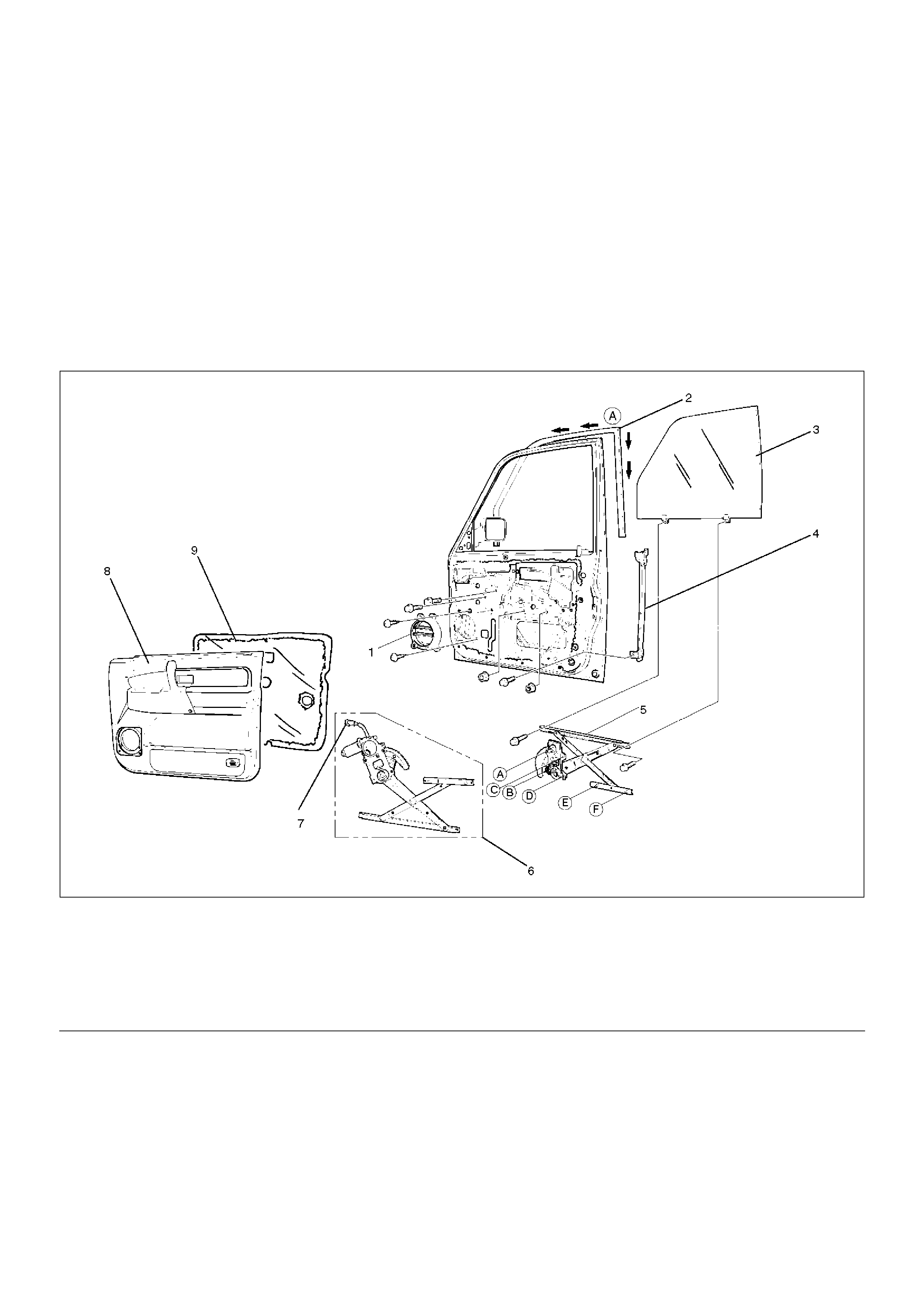
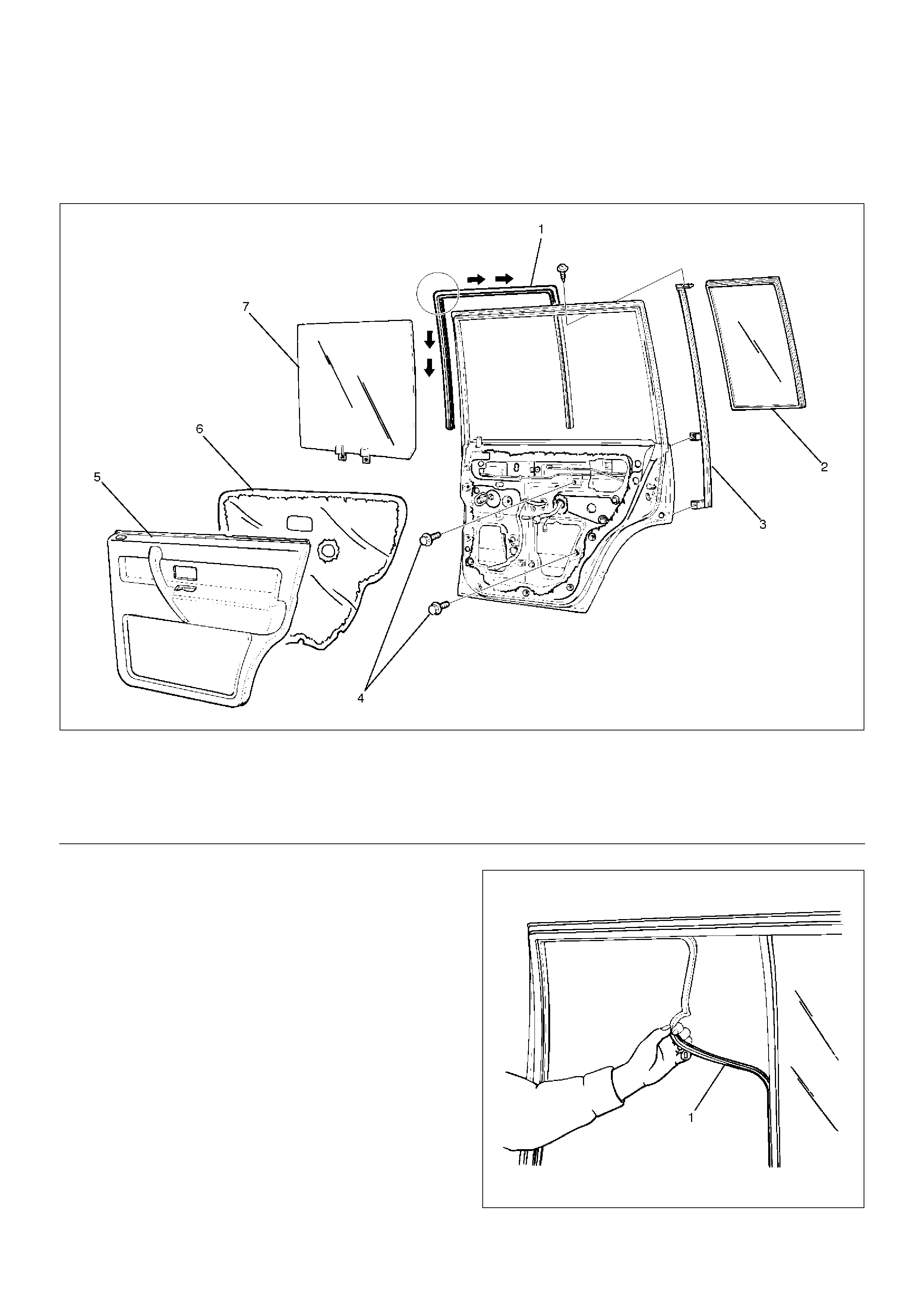
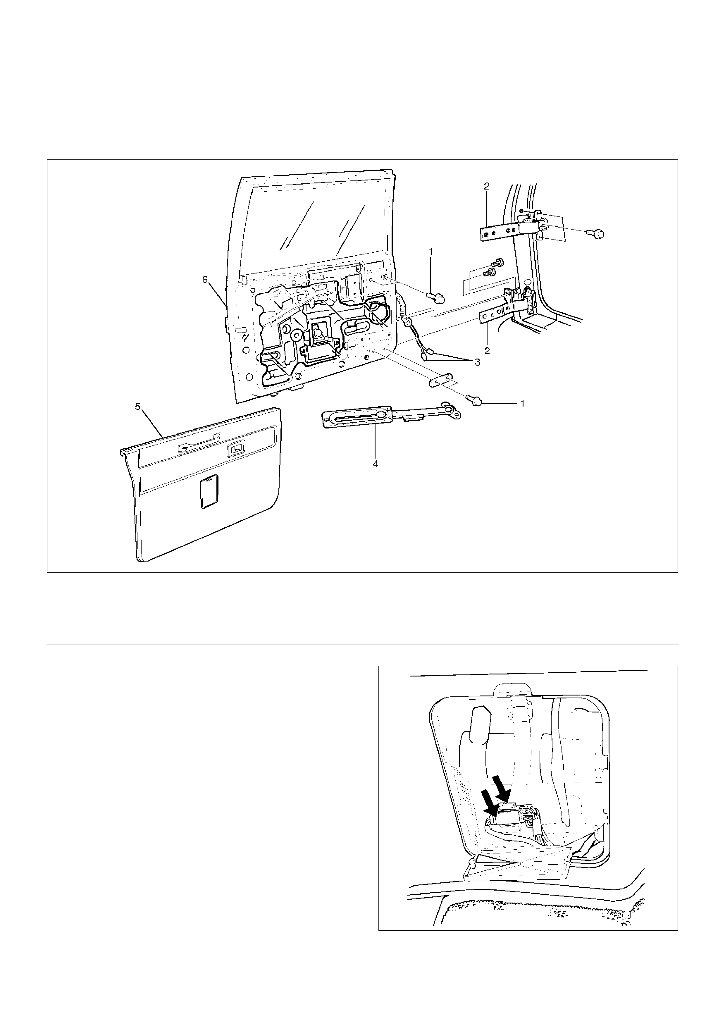
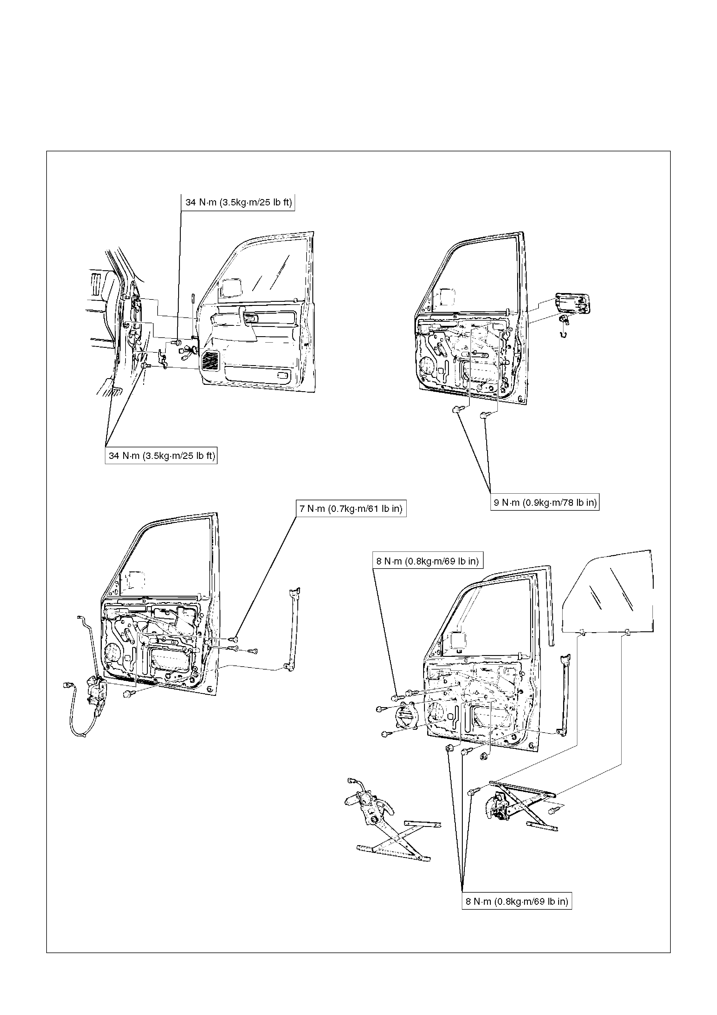
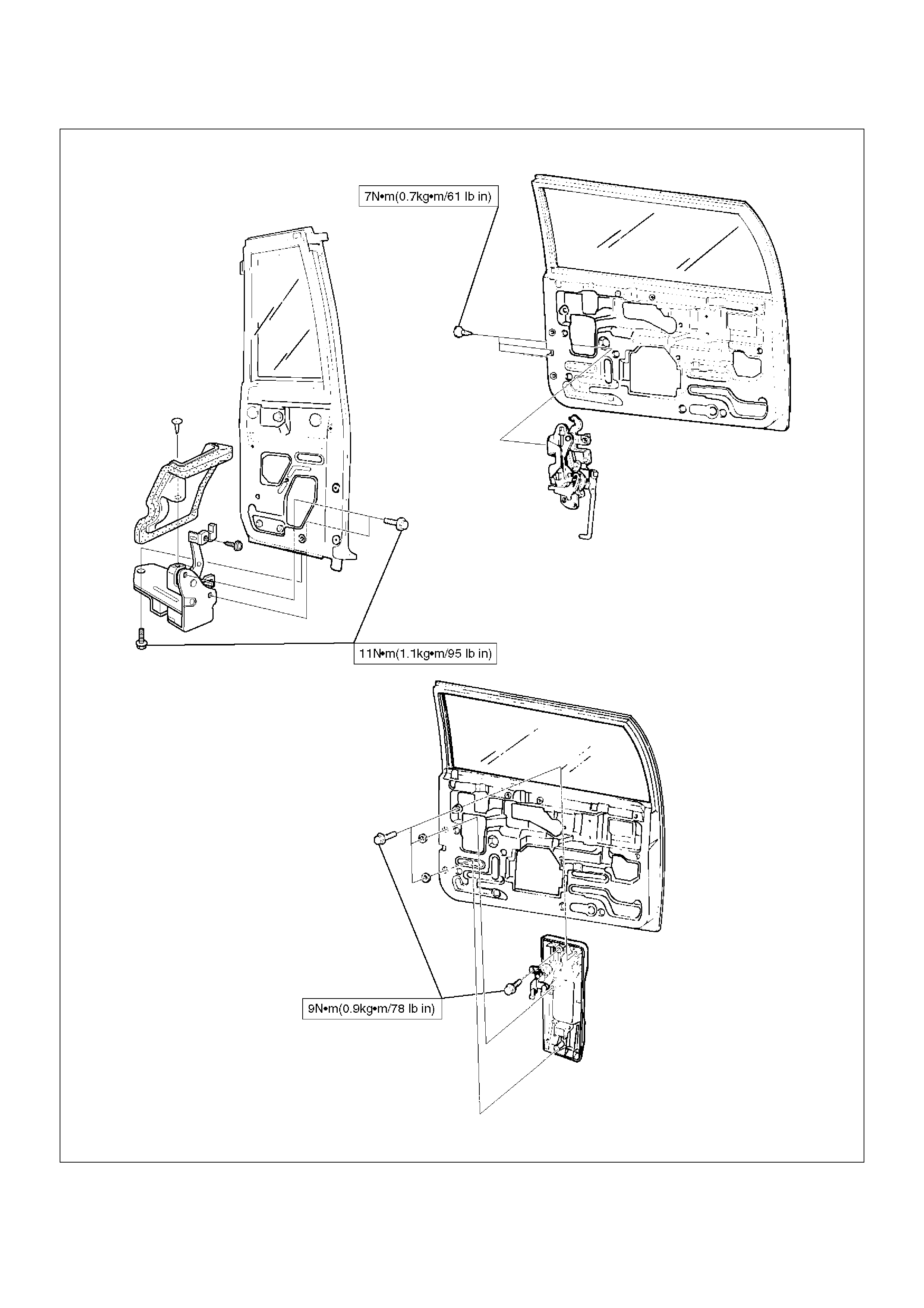
Front Window Regulator, Glass And Glass Run
Parts Location
631RS002
EndOFCallout
Removal
1.Disconnect the battery ground cable.
2.Remove door trim panel.
•Refer to Front Door Trim Panel in Exterior /
Interior section.
3. Remove speaker box.
Legend
(1) Speaker Box
(2) Glass Run
(3) Glass
(4) Rear Guide Rail
(5) Window Regulator
(6) Window Regulator with Power Window
(7) Window Regulator Motor Connector
(8) Door Trim Panel
(9) Waterproof Sheet
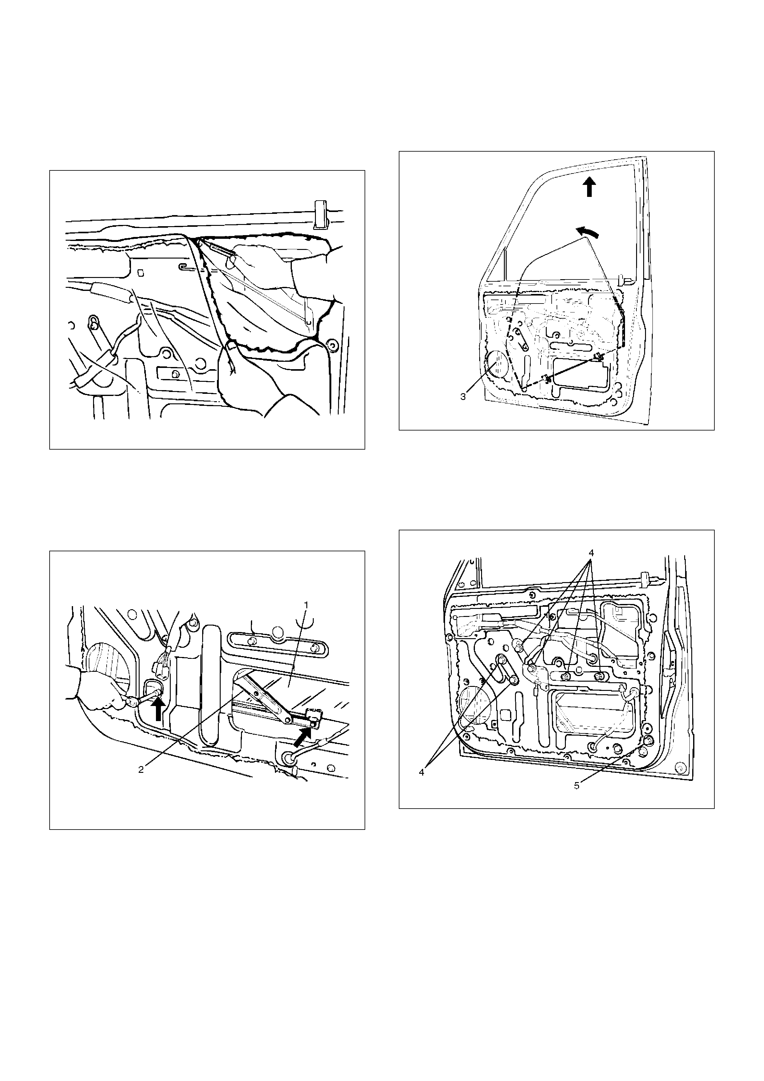
4. Remove waterproof sheet.
• Take notice of the door harness and the
grommet, peel the waterproof sheet off the door
panel carefully.
631RS003
5. Remove glass.
• Bring the glass (1) down to the position where the
fixing bolts can be seen.
• Remove the glass fixing bolts from the window
regulator (2) and lower the front side of the glass.
631RS004
• When the front side of the glass comes off the
glass run (3), turn the glass inside out and pull it
up from its rear side.
631RS005
6. Remove window regulator.
• Remove the window regulator fixing bolts (4) and
the rear guide rail fixing bolt (5).
• Disconnect the window regulator motor harness
connector, if equipped with power windows.
631RS006
7. Remove glass run.
• Pull the glass run (6) out from the door frame
groove.
631RS007
8. Remove rear guide rail.
Installation
To install, follow the removal steps in the reverse order,
noting the following points.
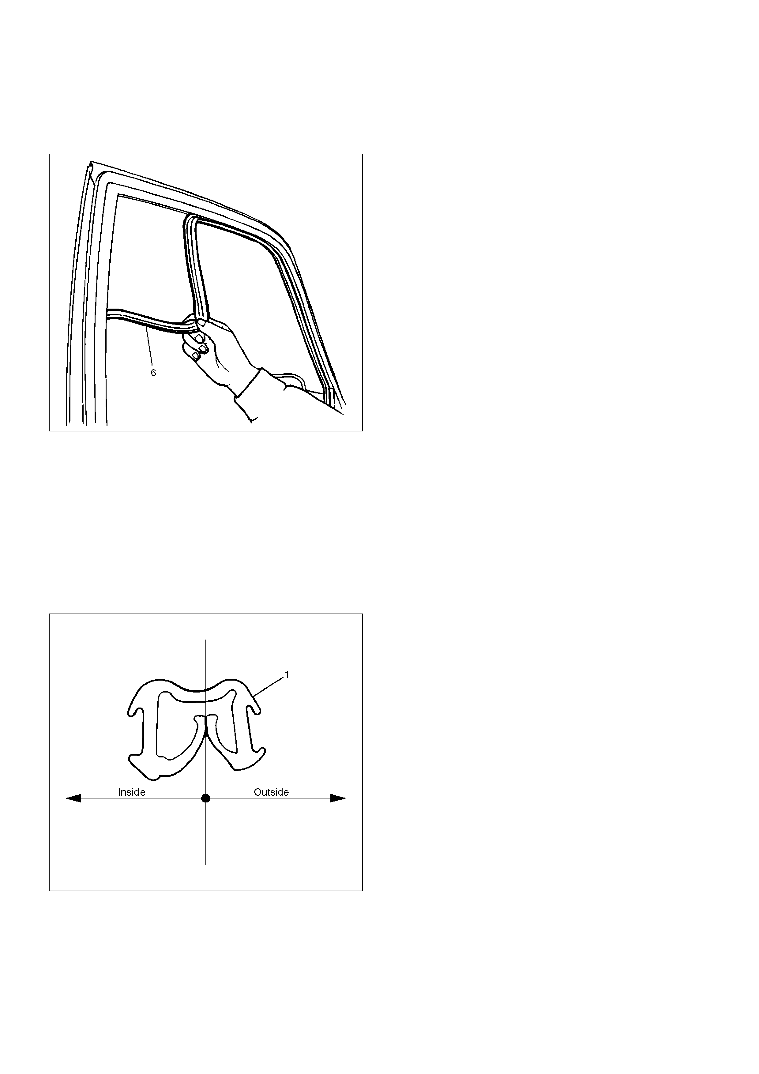
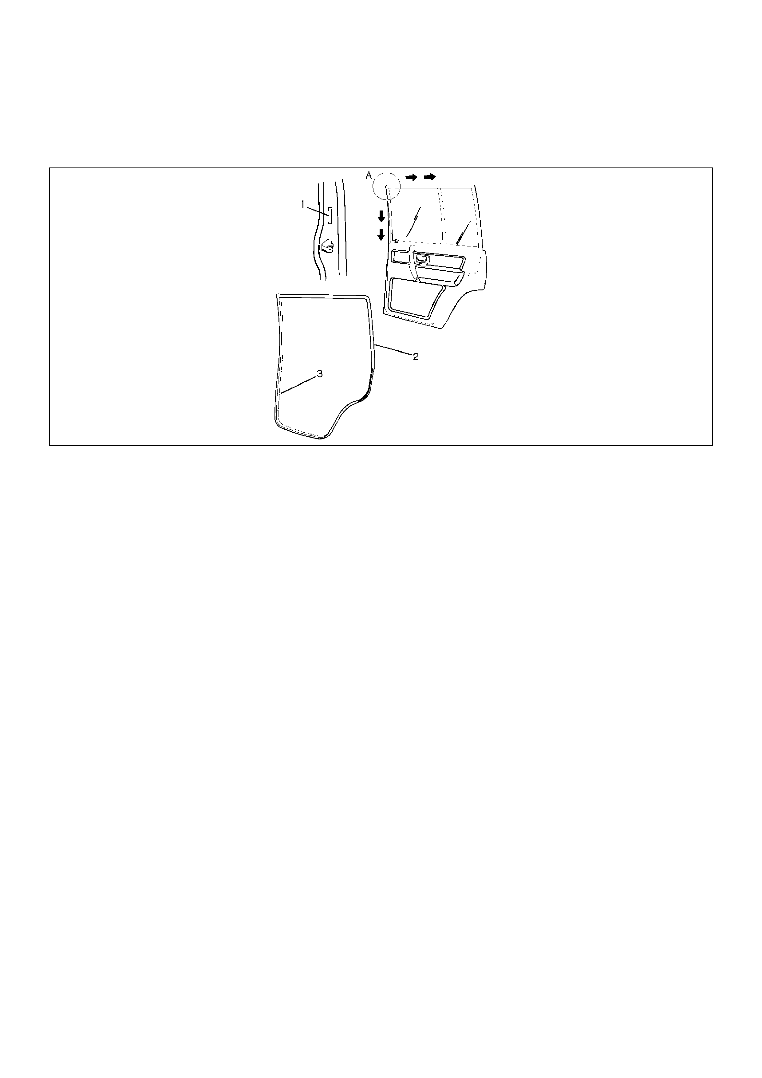
1. Apply soap and water to the door frame groove.
Insert the glass run (1) to the door frame from the A
corner in the arrow-marked directions.
Install the glass run with its wider end pointed to the
inside of the vehicle.
A10RS023
2. Set the glass into the door panel with the front side
of the glass lowered and insert the rear side of the
glass into the glass run (1). Then insert the front
side of the glass into the glass run in order to install
the glass to the glass run while raising it up along
the glass run.
3. Tighten the window regulator and the glass fixing
bolts and nuts to the specified torque.
Torque : 8 N•m (0.8kg·m/69 lbin)
4. Check to see of the window regulator operates
smoothly and the glass opens and closes properly.
Install the waterproof sheet with no clearance
between the door panel and the waterproof sheet.
Rear Window Regulator And Glass
Parts Location
651RW018
EndOFCallout
Removal
1.Disconnect the battery ground cable.
2.Remove door trim panel.
•Refer to Rear Door Trim Panel in Exterior /
Interior Trim section.
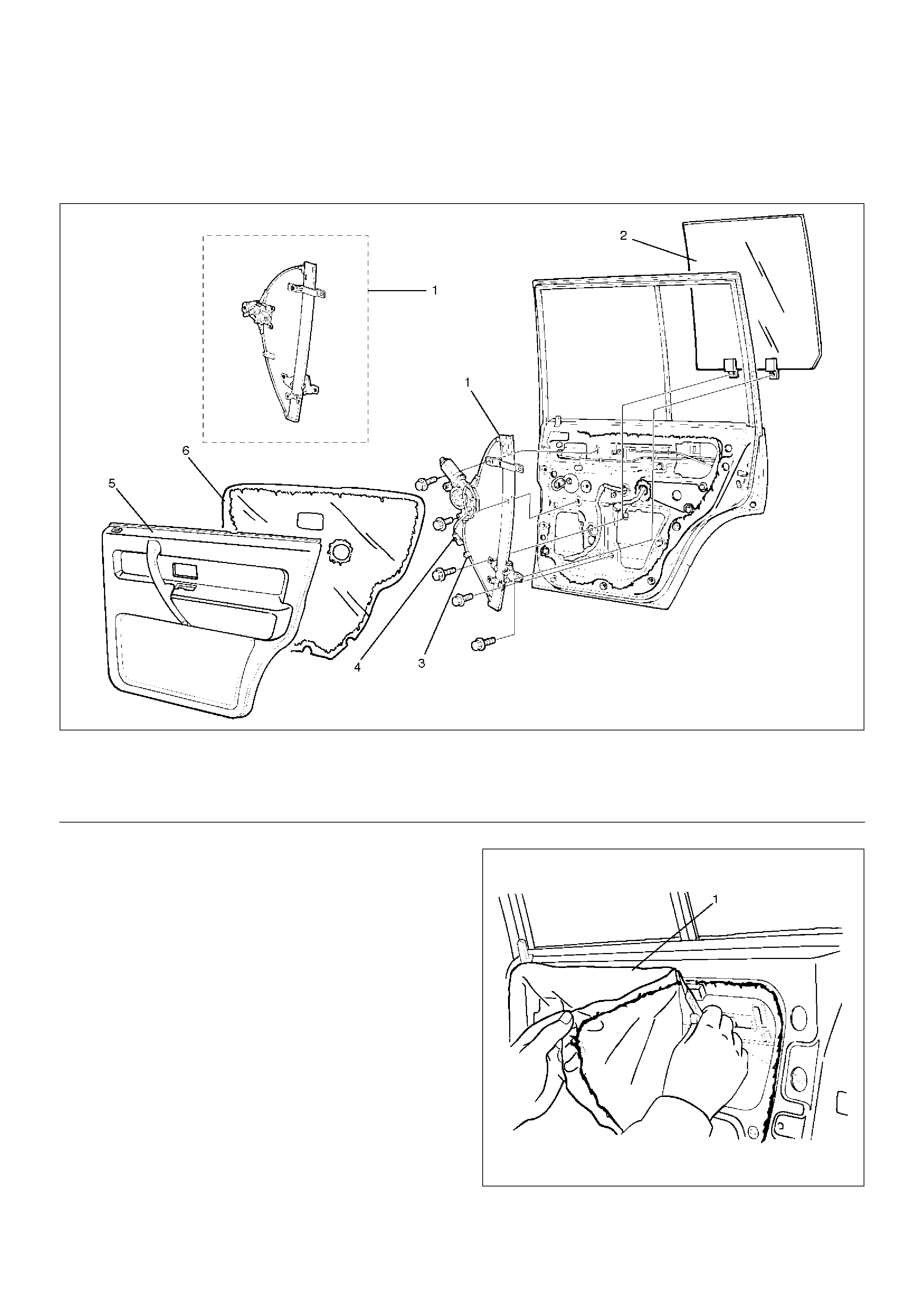
3. Remove waterproof sheet (1).
• Taking notice of the door harness, peel the
waterproof sheet off the door panel carefully.
651RS002
4. Remove glass.
Legend
(1) Window Regulator
(2) Glass
(3) Cable Fixing Clip
(4) Window Regulator Motor Connector
(5) Door Trim Panel
(6) Waterproof Sheet
• Bring the glass down to the position where the
bolt can be seen.
• Remove the sash division 2 fixing bolts (1) and
then remove the glass fixing bolt to remove the
glass upwards.
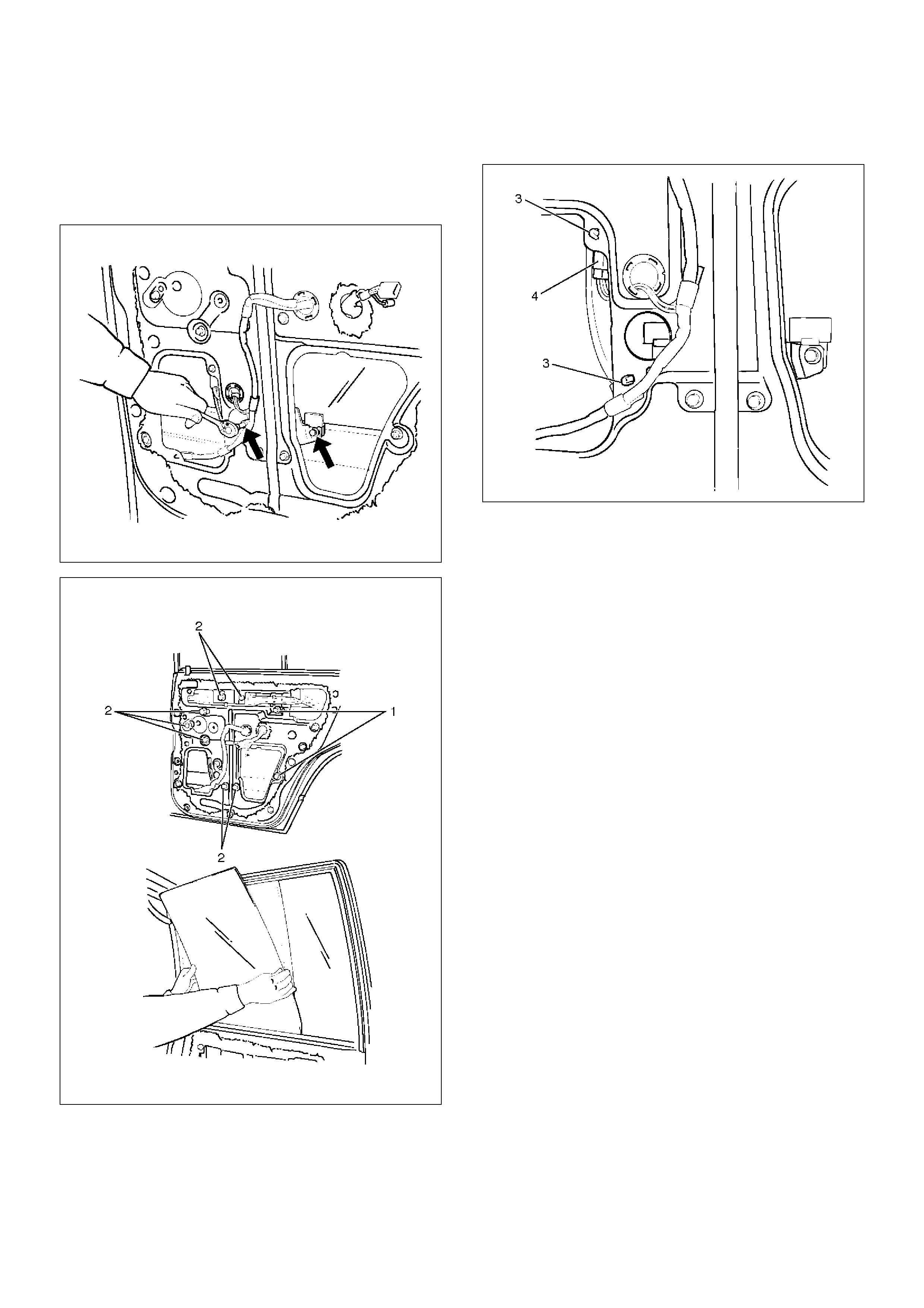
651RS003
651RW010
5. Remove window regulator.
• Disconnect the regulator motor connector (4) and
remove the window regulator cable fixing clip (3)
from the door panel, if model is equipped with
power windows.
• Remove the window regulator 7 fixing bolts (2)
and pull the regulator out from the lower hole of
the door panel.
651RW011
Installation
To install, follow the removal steps in the reverse order,
noting the following points.
1. Tighten the window regulator and the glass fixing
bolts to the specified torque.
Torque : 8 N•m (0.8kg·m/69 lbin)
2. Install the waterproof sheet with no clearance
between the door panel and the waterproof sheet.
Rear Door Fixed Glass And Glass Run
Parts Location
651RW019
EndOFCallout
Removal
1.Disconnect the battery ground cable.
2.Remove door trim panel.
3.Remove waterproof sheet.
4.Remove glass.
•Refer to Window Regulator and Glass in this
section.
5. Remove glass run.
• Pull the glass run (1) out from the door frame.
651RS007
6. Remove sash division (2).
Legend
(1) Glass Run
(2) Rear Fixed Glass
(3) Sash Division
(4) Sash Division Fixing Bolts
(5) Door Trim Panel
(6) Waterproof Sheet
(7) Glass
651RS008
7. Remove door fixed glass.
Installation
To install, follow the removal steps in the reverse order,
noting the following points.
1. Apply soap and water to the fixed glass.
2. Apply soap and water to the door groove and insert
the glass run (3) to the frame from the corner in the
arrow-marked directions.
3. Be sure to install the glass run with its end pointed
to the inside of the vehicle.
A10RW019
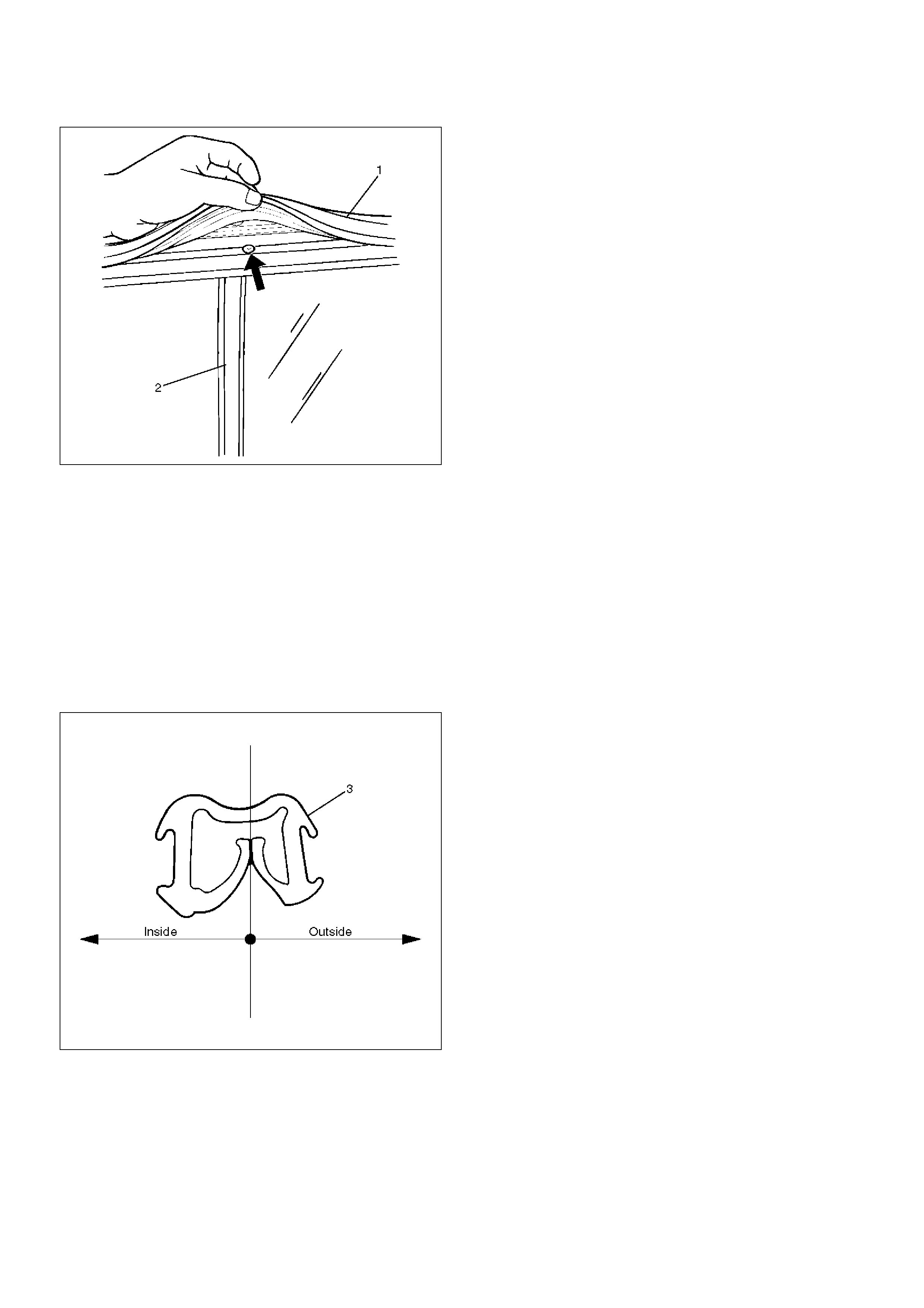
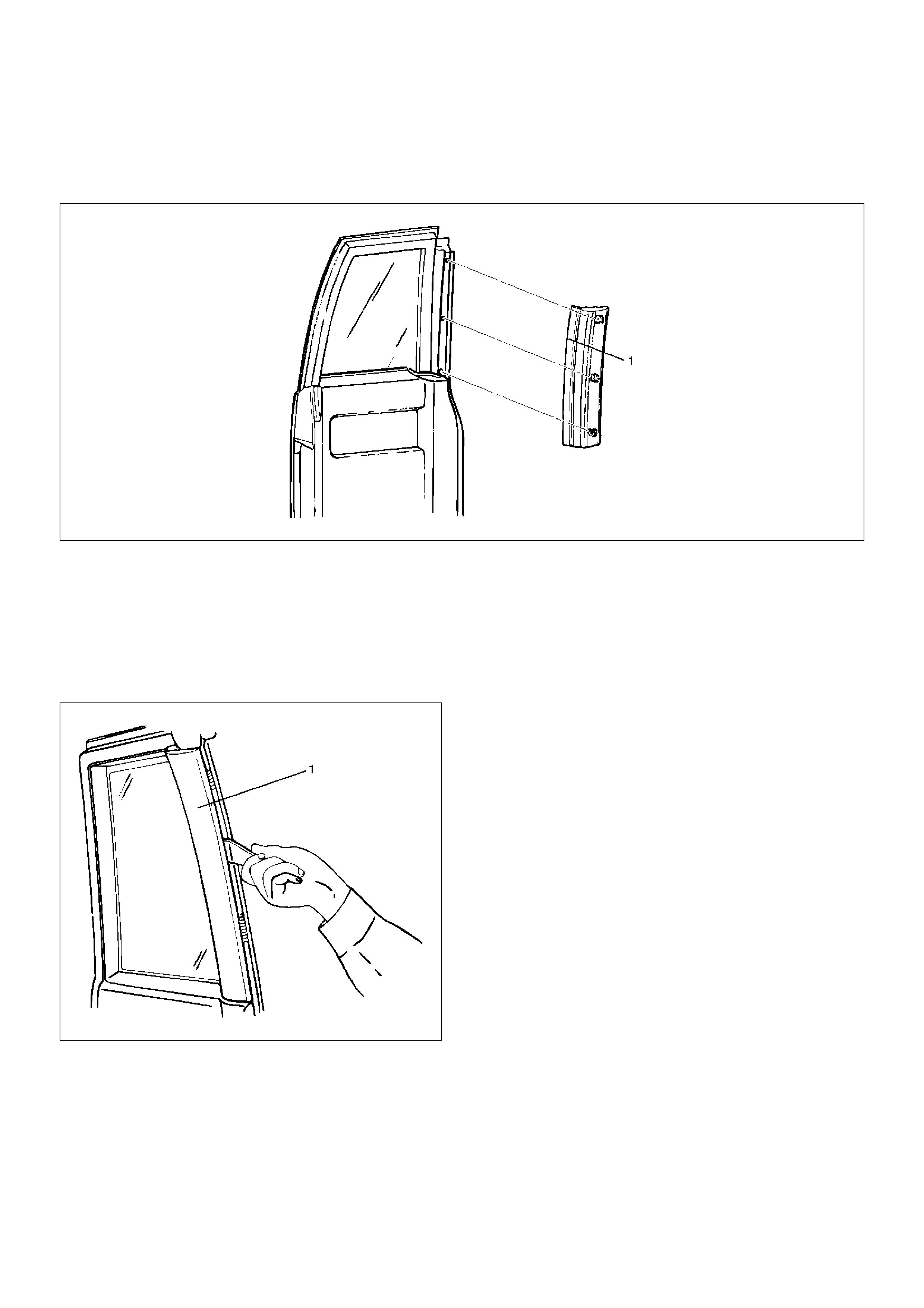
Front Door Sash Moulding
Parts Location
645RS001
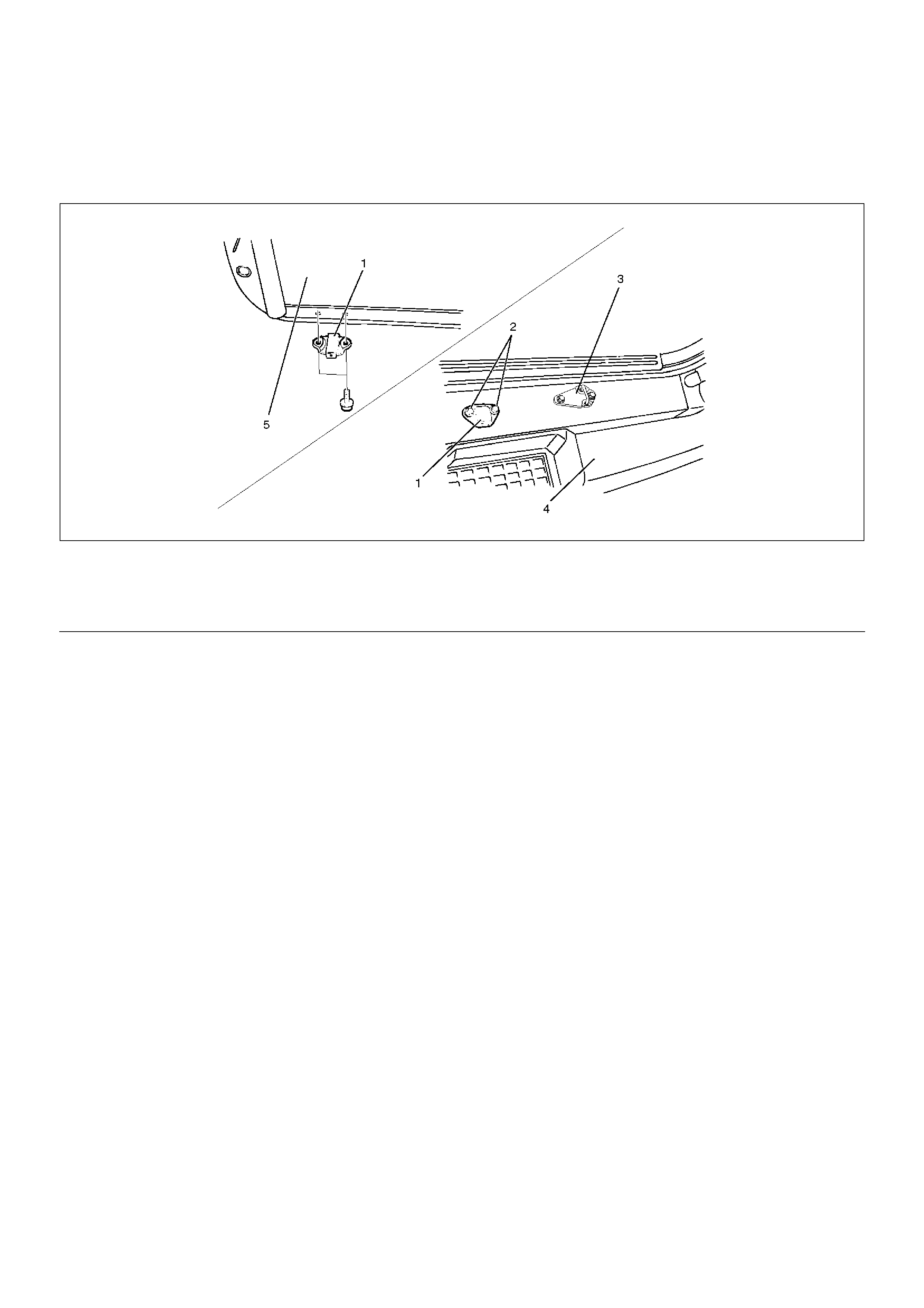
tRemoval
1. Remove front door slash moulding.
• To avoid the weatherstrip (1) and pry the door
sash moulding (2) out from the door panel.
645RS002
Installation
1. Install the front door sash moulding.
• Assemble the edge portion (A portion) of the
moulding so that the clearance between the
moulding and the waist seal becomes 1 mm (0.04
in).
Legend
(1) Front Door Sash Moulding
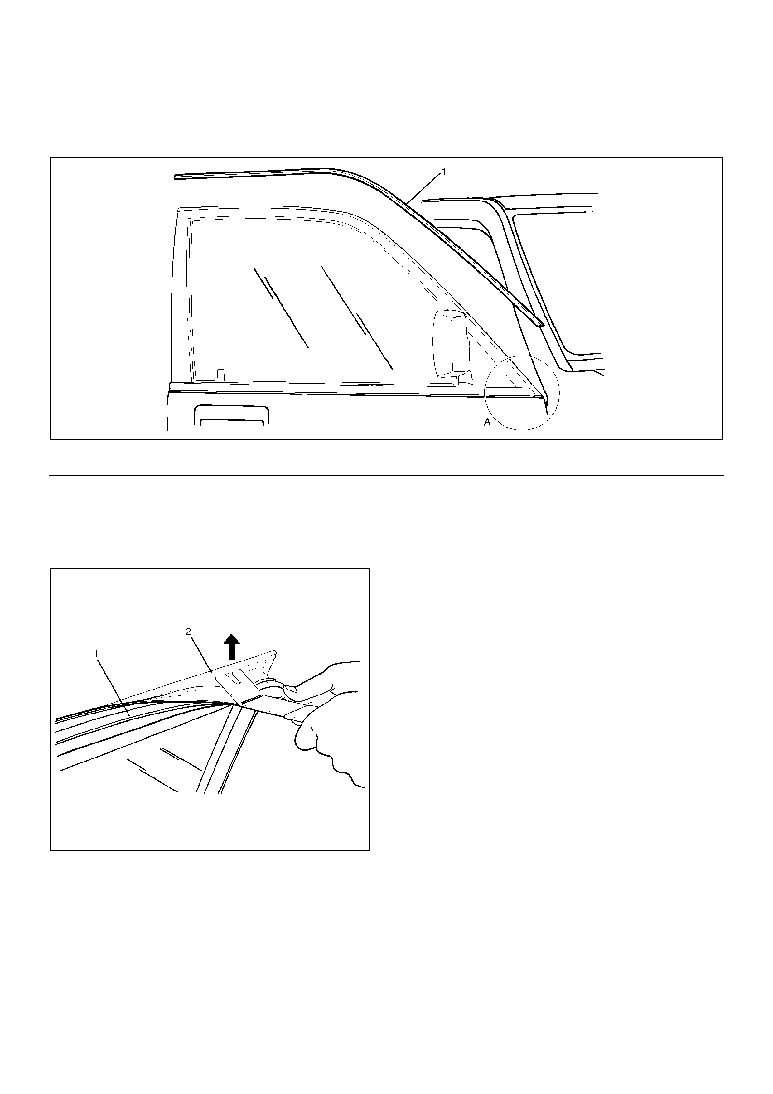
Rear Door Moulding
Parts Location
645RS003
EndOFCallout
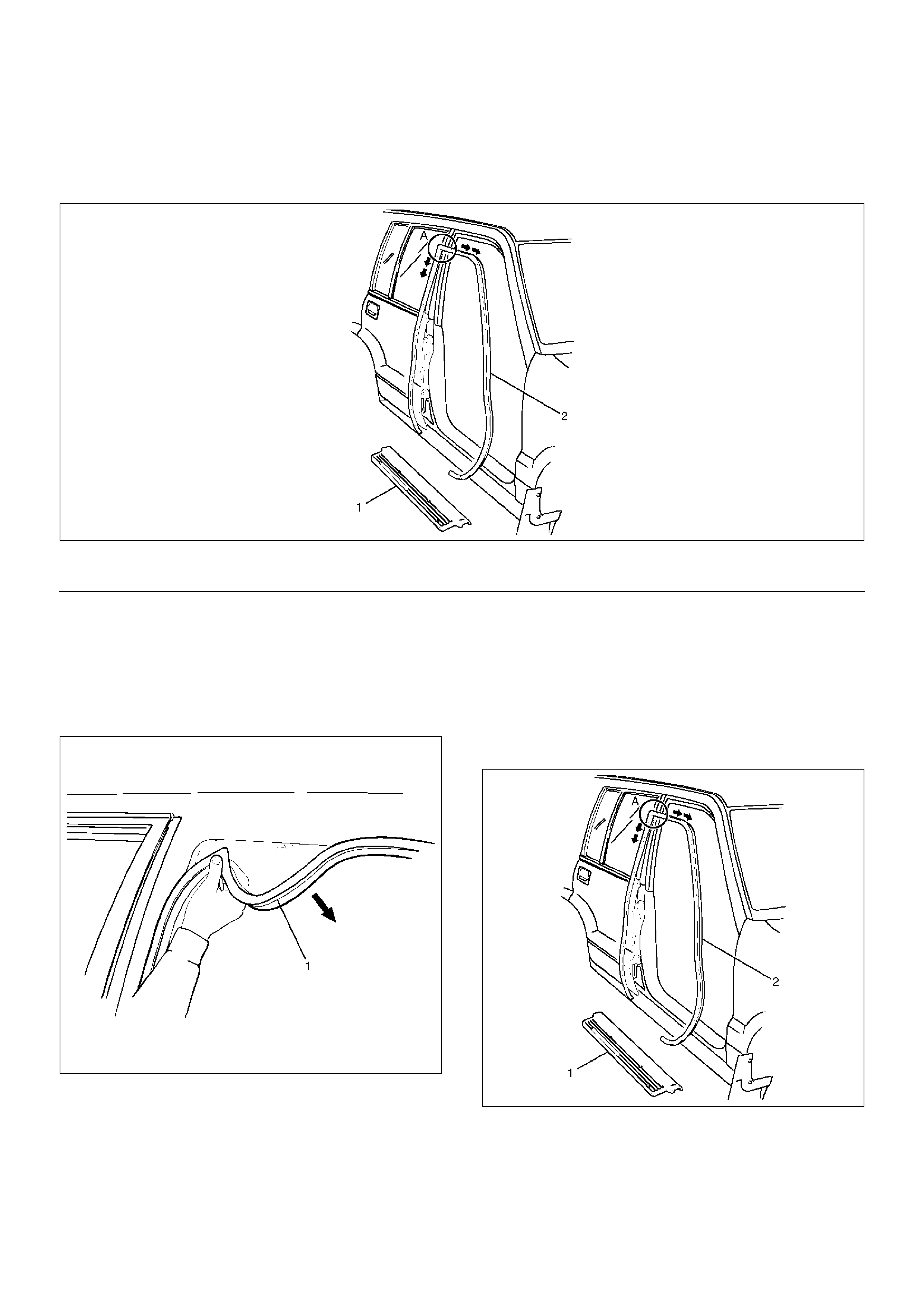
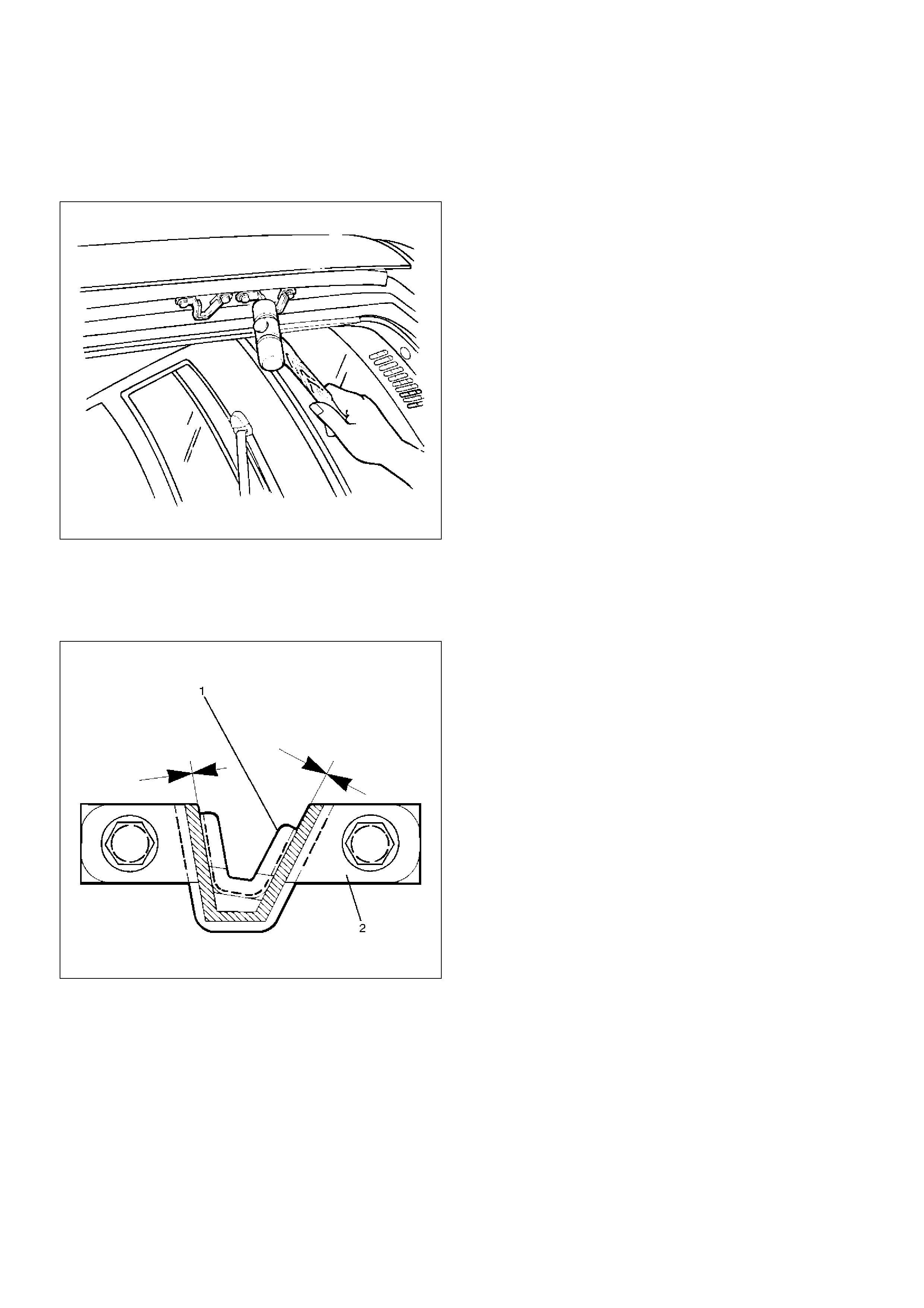
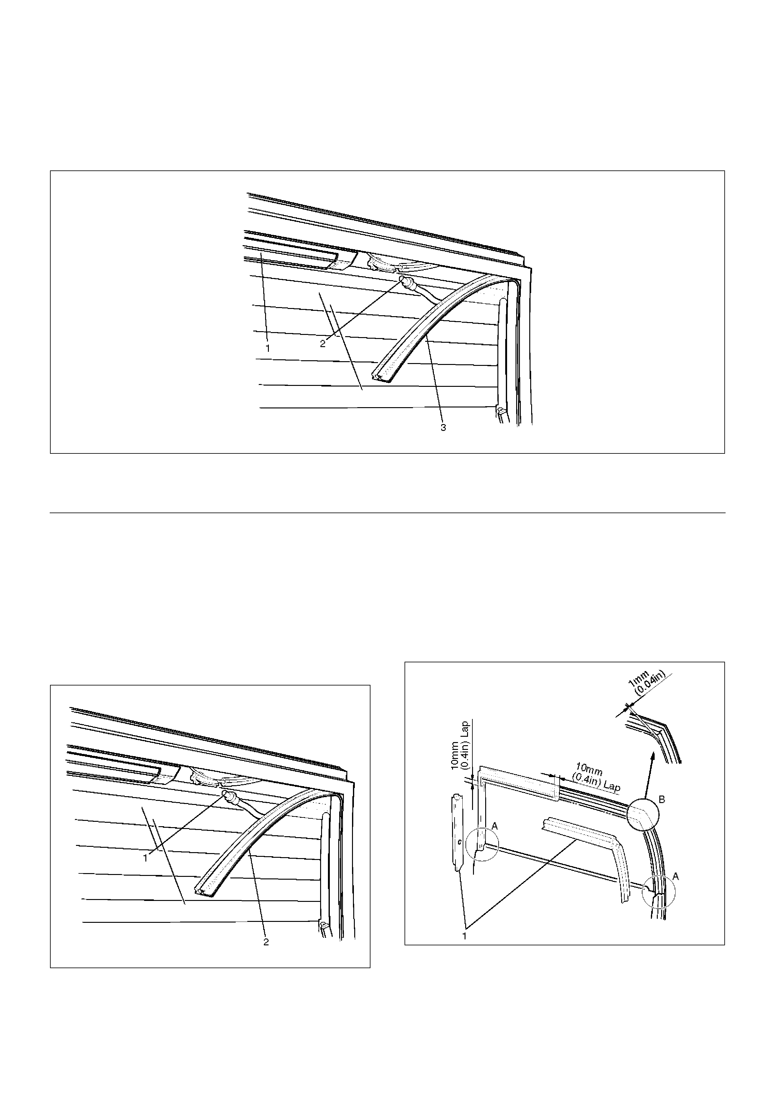
Removal
1. Disconnect the battery ground cable.
2. Remove rear door side moulding.
3. Remove rear door upper moulding.
4. Remove rear door corner moulding.
• Avoiding the weatherstrip (3), pry the moulding
(2) out from the door frame (1).
645RS004
Installation
To install, follow the removal steps in the reverse order,
noting the following points.
1. Install each moulding with no clearance between
each piece of moulding.
2. Assemble the edge portion (A portion) of the
moulding so that the clearance between the rear
side moulding and the waist seal is 1 mm (0.04 in).
Legend
(1) Rear Door Side Moulding
(2) Rear Door Corner Moulding
(3) Rear Door Upper Moulding
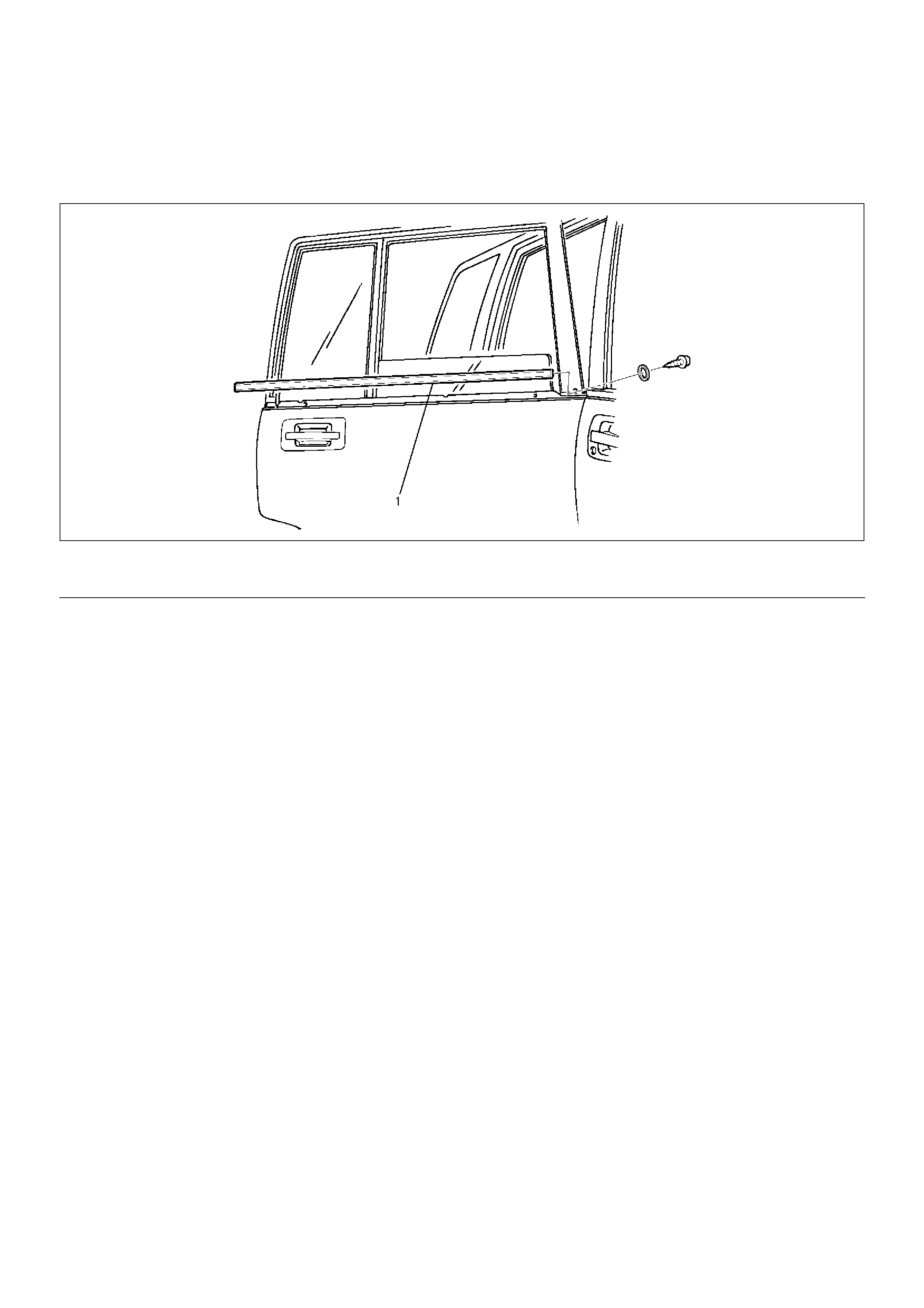
Front Door Waist Seal
Parts Location
631RS009
EndOFCallout
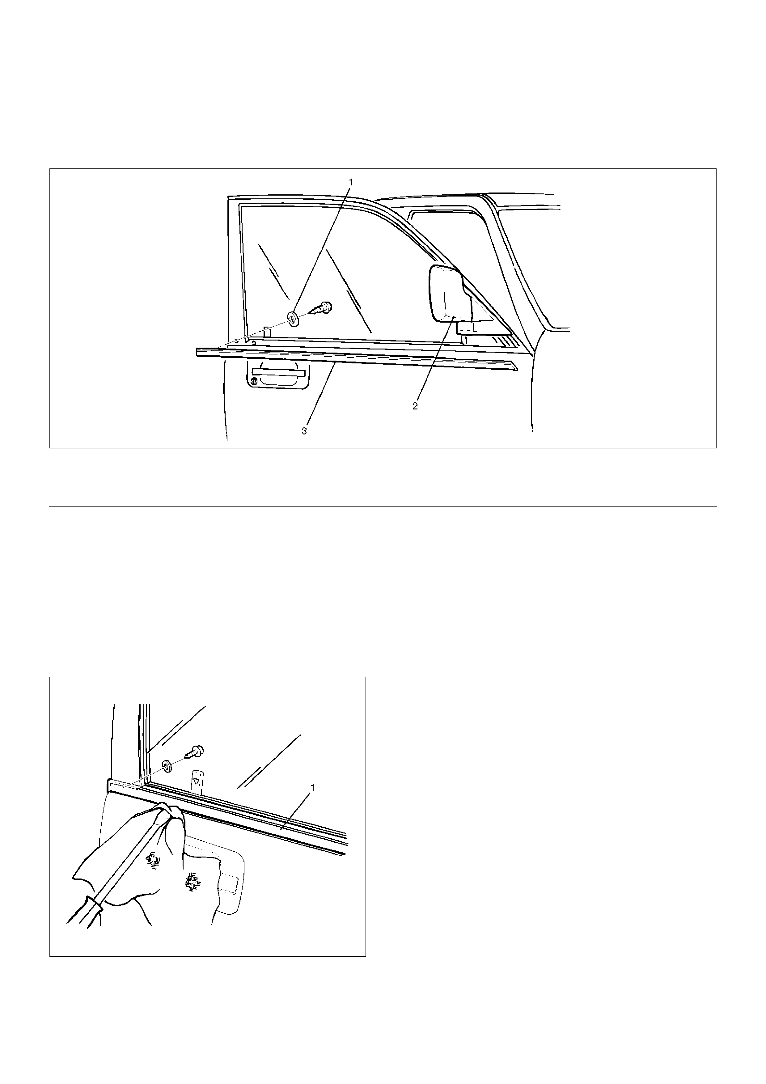
Removal
1.Disconnect the battery ground cable.
2.Remove door mirror.
•Refer to Door Mirror in Exterior / Interior Trim
section.
3. Remove front door waist seal.
• Remove the fixing screw and pull out the waist
seal (1) from the door frame while prying it up.
631RS010
Installation
To install, follow the removal steps in the reverse order,
noting the following points.
1. Apply soap and water to the inside of the waist seal
and align the screw hole of the waist seal to the
door panel hole, and gently tap the seal with a
rubber hammer.
Be sure not to tap the seal hard. This may result in
deforming the seal.
Legend
(1) Nylon Washer
(2) Door Mirror
(3) Front Door Waist Seal
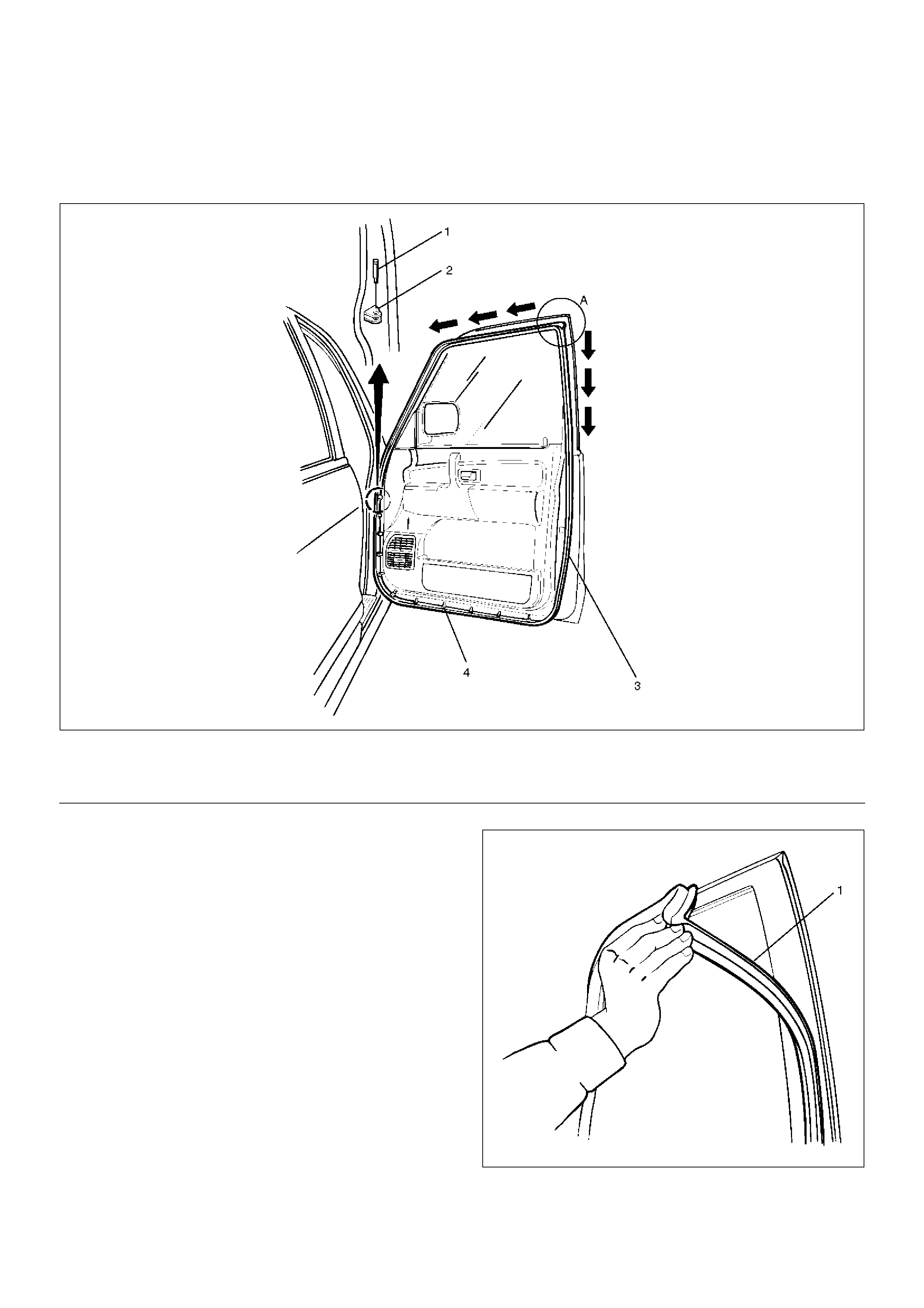
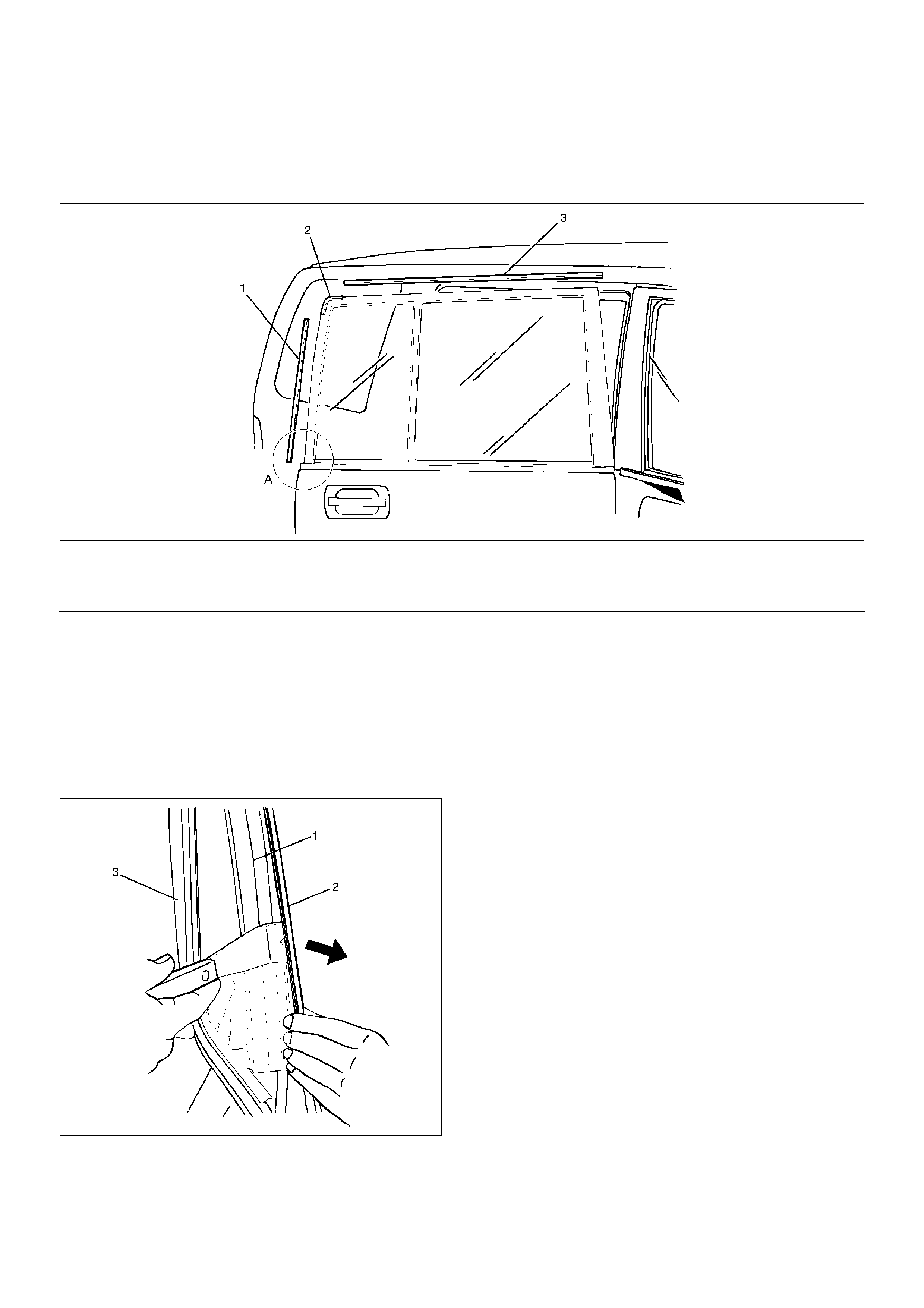
Front Door Weatherstrip
Parts Location
631RS008
EndOFCallout
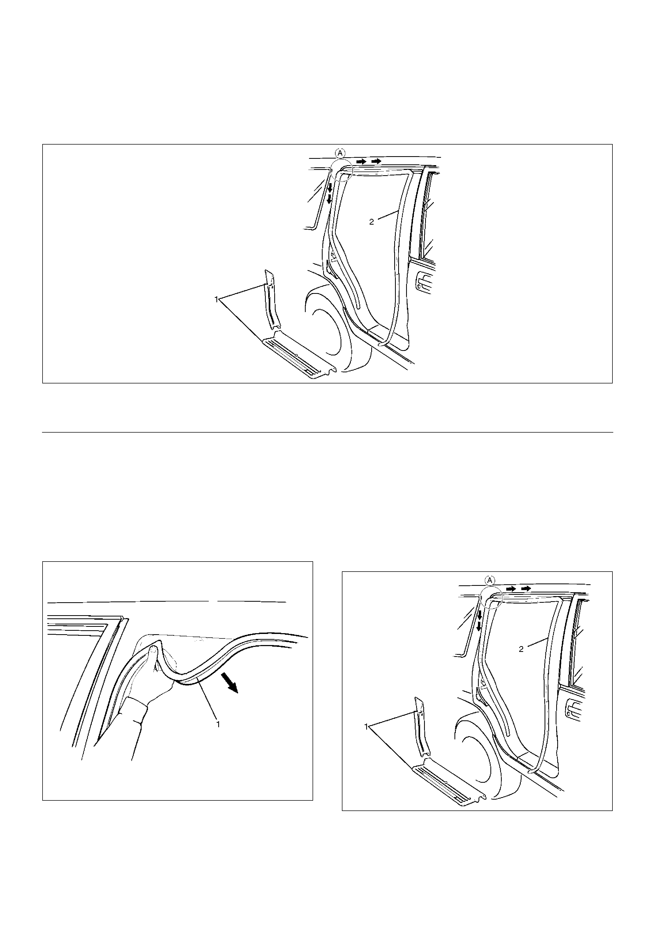
Removal
1. Remove check arm pin.
2. Remove front door weatherstrip.
• Pull the weatherstrip (1) out from the door frame.
631RS011
Legend
(1) Check Arm Pin
(2) Bracket
(3) Weather Strip
(4) Clip
• Carefully remove the weatherstrip (2) from the
door panel.
631RW003
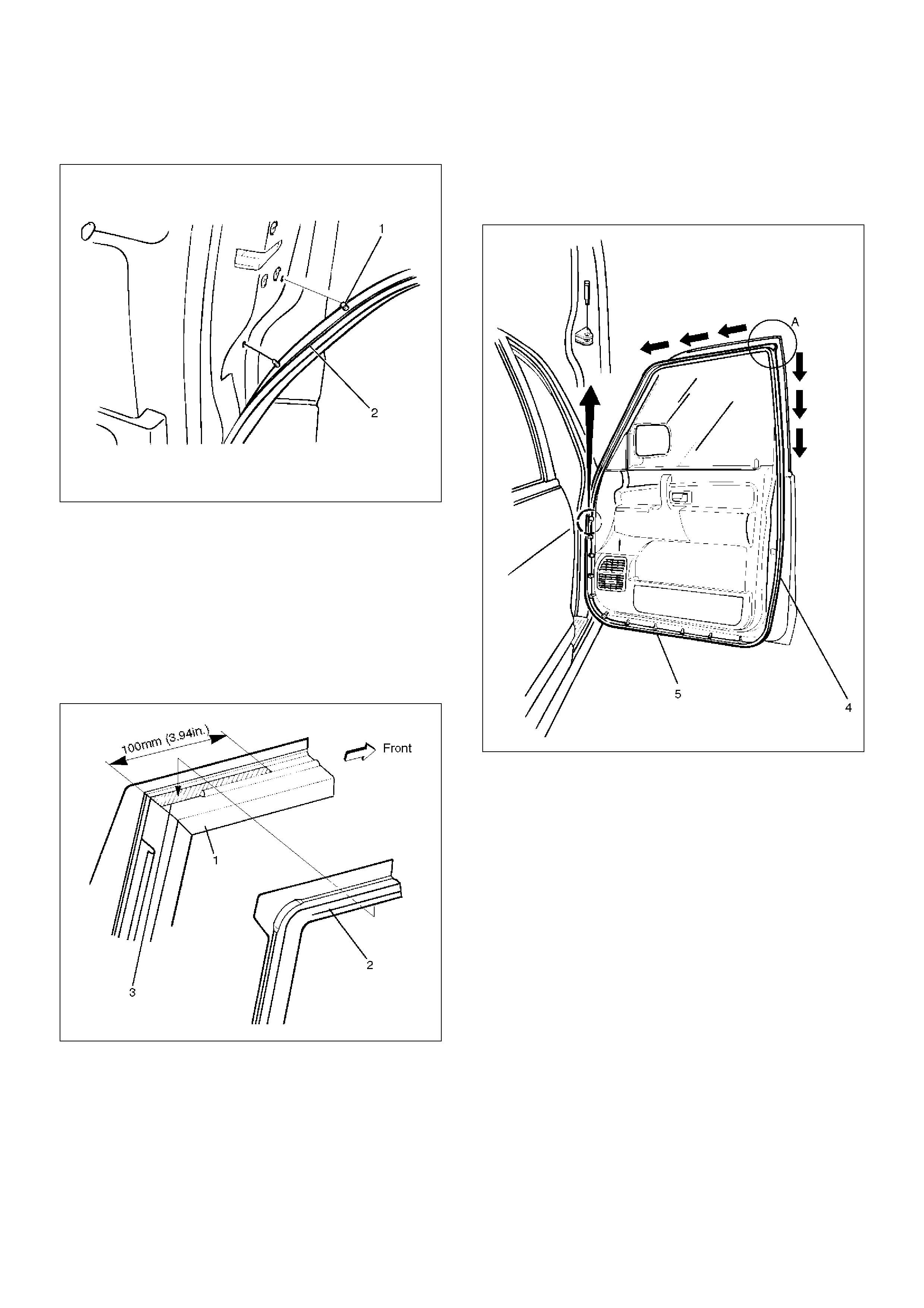
Installation
To install, follow the removal steps in the reverse order,
noting the following points.
1. Apply soapy water to the door frame groove when
installing the front door weather strip (2).
2. Apply the sealing adhesive (3) to the upper A
portion of the door frame (1) and press it for
installation after assembling the weatherstrip (2).
631RS013
3. After positioning the weatherstrip (4) corner, insert
the weatherstrip into the door frame groove from A
point in the arrow-marked direction.
4. Insert the weatherstrip clip (5) into the door panel up
to its base.
631RW009
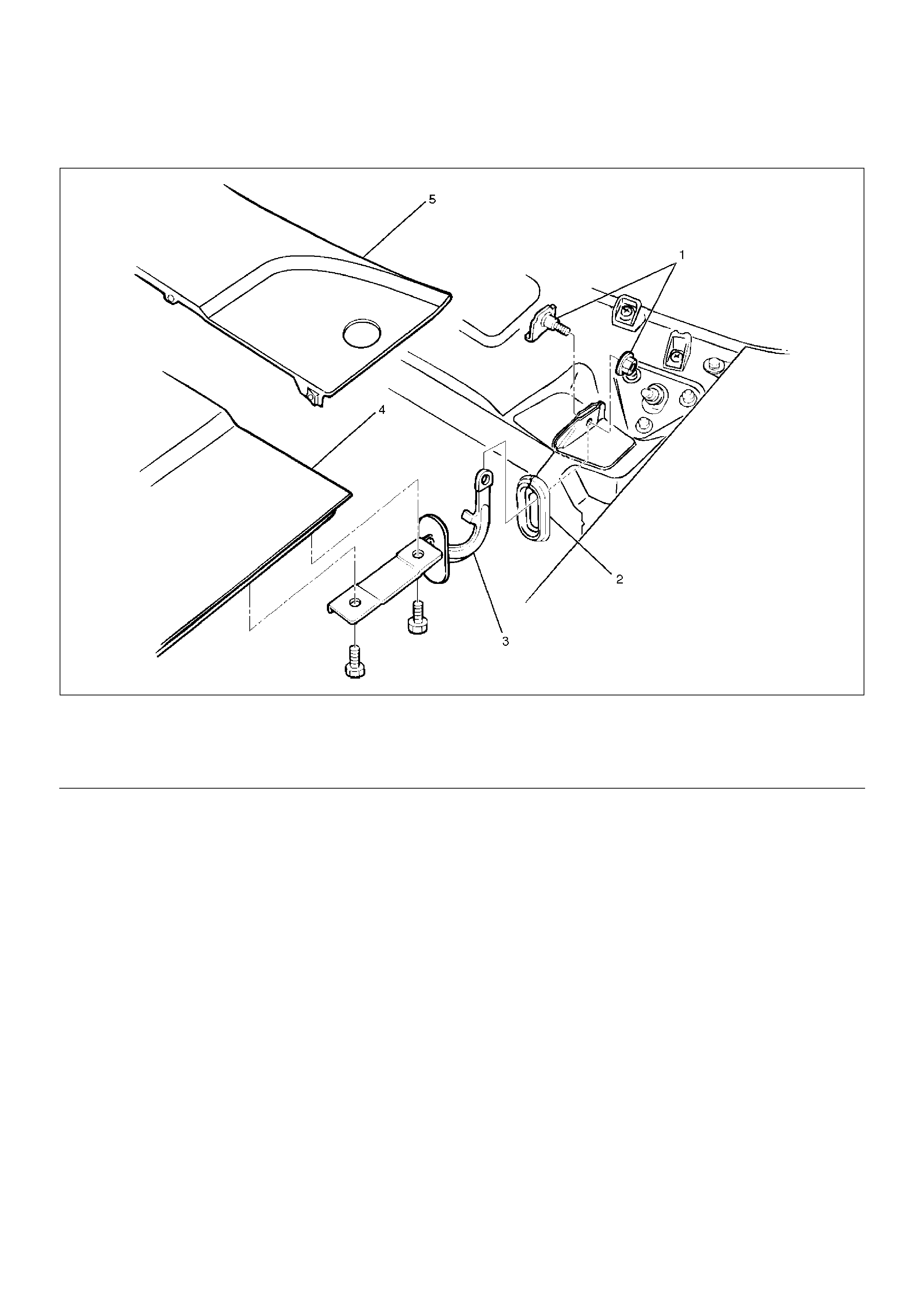
Front Door Seal Finisher
Parts Location
635RS002
EndOFCallout
Removal
1. Disconnect the battery ground cable.
2. Remove front door sill plate.
3. Remove front door seal finisher (1).
• Pull the finisher out from the body panel.
635RS003
Installation
To install, follow the removal steps in the reverse order,
noting the following points.
1. Insert the finisher into the A corner and install the
finisher (2) in the arrow-marked directions.
2. Take care not to allow the sill plate (1) to distort or
twist the finisher.
635RS002
Legend
(1) Front Door Sill Plate (2) Front Door Seal Finisher
Rear Door Seal Finisher
Parts Location
655RS002
EndOFCallout
Removal
1. Disconnect the battery ground cable.
2. Remove rear door sill plate and the luggage side
lower cover.
3. Remove rear door seal finisher (1).
• Pull the rear door seal finisher (1) out from the
body panel.
635RS003
Installation
To install, follow the removal steps in the reverse order,
noting the following points.
1. Insert the rear door seal finisher (2) into the A corner
and install the finisher in the arrow-marked
directions.
2. Be careful not to allow the sill plate and cover (1) to
distort or twist the finisher.
655RS002
Legend
(1) Rear Door Sill Plate and Luggage Side Lower
Cover
(2) Rear Door Seal Finisher
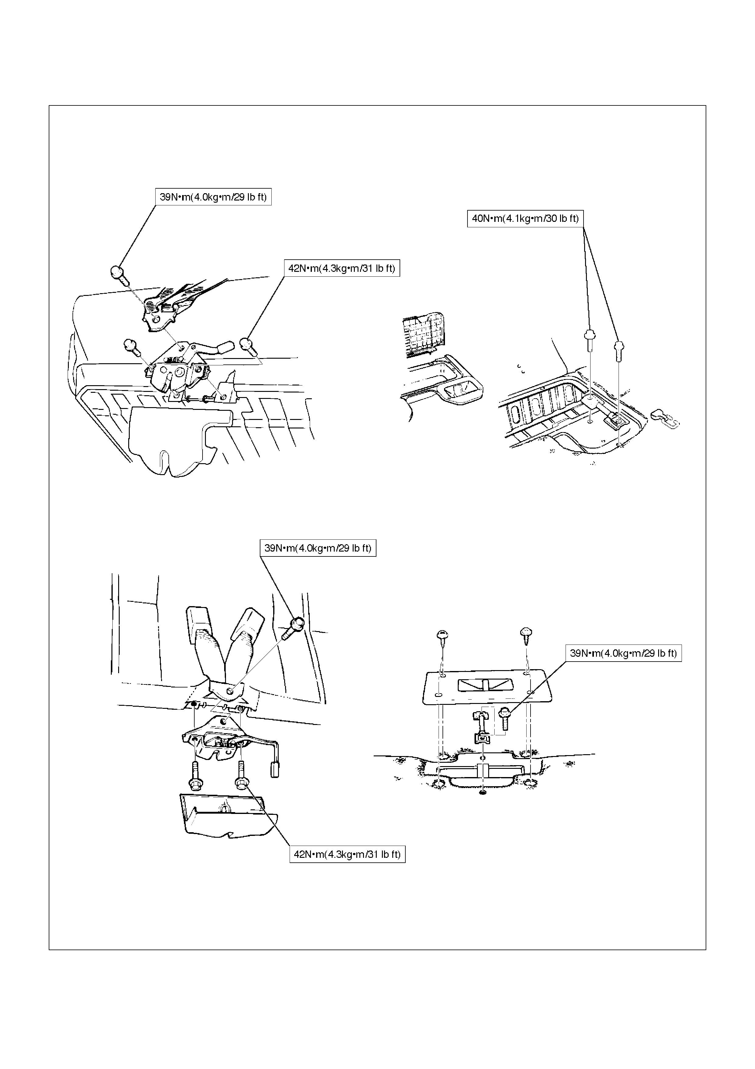
Tailgate Assembly (LH)
Parts Location
681RW008
EndOFCallout
Removal
1.Disconnect the battery ground cable.
2.Remove tailgate time panel (LH).
•Refer to Tailgate Trim Panel (LH) in Exterior /
Interior Trim section.
3. Remove tailgate stopper assembly
4. Remove tailgate harness connection.
• Open the luggage trim panel lid and disconnect
the tailgate harness connection.
810RS003
5. Remove tailgate fixing bolts.
Legend
(1) Tailgate Fixing Bolt
(2) Tailgate Hinge
(3) Tailgate Harness Connection
(4) Tailgate Stopper Assembly
(5) Tailgate Trim Panel (LH)
(6) Tailgate Assembly (LH)
681RS002
6.Remove tailgate assembly (LH).
7.Remove tailgate hinge.
•Apply a setting mark (1) on the body side hinge
and remove the hinge fixing bolts.
681RW007
Installation
To install, follow the removal steps in the reverse order,
noting the following points.
1.Apply chassis grease to the tailgate hinge and the
tailgate stopper moving surface.
2.Align the tailgate fitting to the body by referring to
Body Dimension in this section.
3. Tighten the hinge bolts to the specified torque.
Torque : 34 N•m (3.5kg·m/25 lbft)
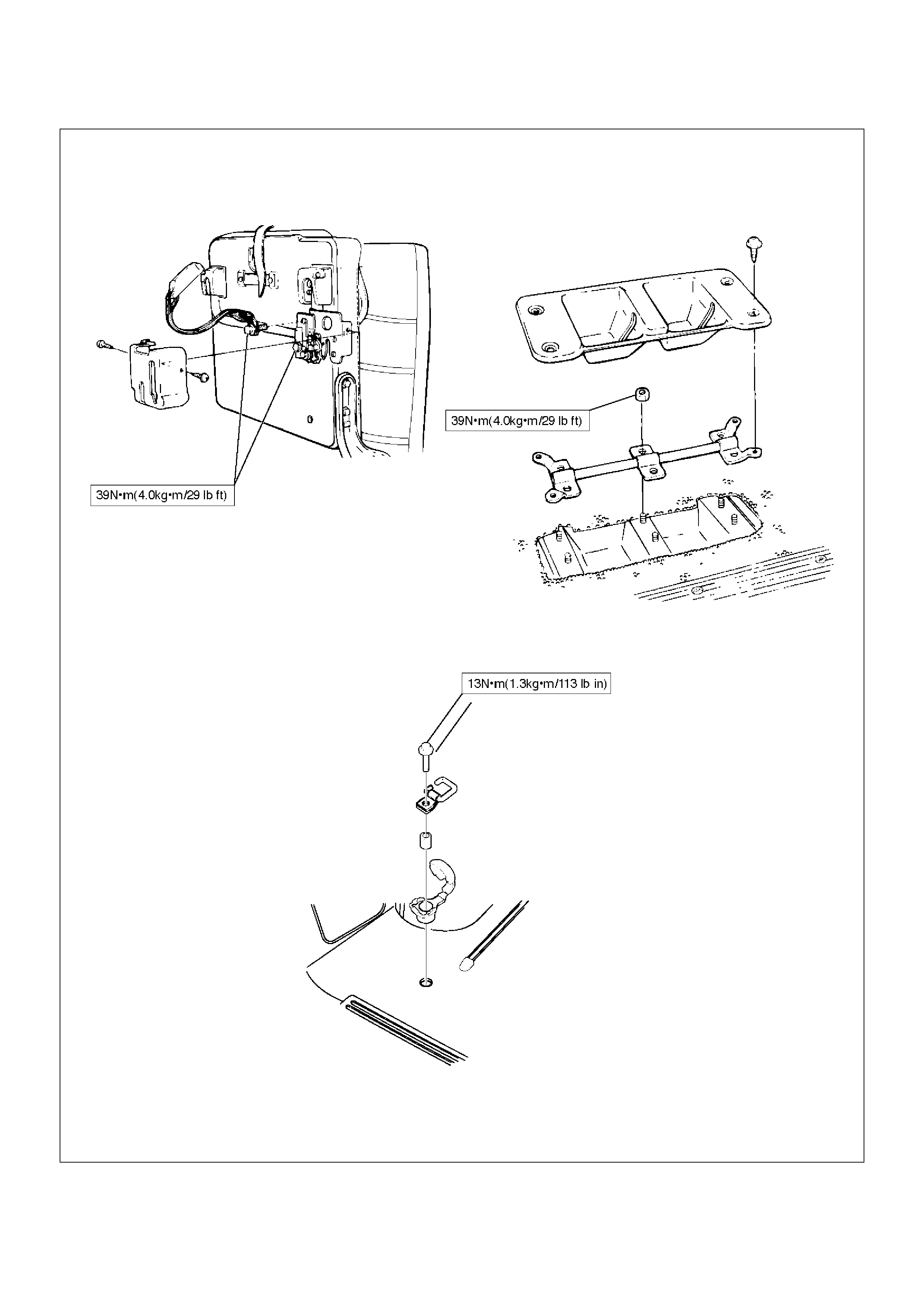
Tailgate Assembly (RH)
Parts Location
681RS004
EndOFCallout
Removal
1.Disconnect the battery ground cable.
2.Remove rear combination light (RH).
3.Remove tailgate trim panel (RH).
•Refer to Tailgate Trim Panel (RH) in Exterior /
Interior section.
4. Remove tailgate harness connection.
• Disconnect the tailgate harness connection.
810RS004
5. Remove tailgate fixing bolt.
Legend
(1) Tailgate Assembly (RH)
(2) Tailgate Trim Panel (RH)
(3) Tailgate Harness Connection
(4) Rear Combination Light (RH)
(5) Tailgate Fixing Bolt
(6) Tailgate Hinge
681RS005
6.Remove tailgate assembly (RH).
7.Remove tailgate hinge.
•Apply a setting mark (1) on the body side hinge
and remove the hinge fixing bolts.
681RW006
Installation
To install, follow the removal steps in the reverse order,
noting the following point.
1.Apply chassis grease to the tailgate hinge moving
surface.
2.Align the tailgate fitting to the body. Refer to Body
Dimension in this section.
3. Tighten the hinge bolts to the specified torque.
Torque : 34N•m (3.5kg·m/25 lbft)
Tailgate Strikers
Adjustment
683RW012
1. Loosen the striker screws (3) (or bolts (2)).
2. Tap the striker (1) with a plastic hammer to align.
3. Tighten the striker screws (3) (or bolts (2)).
Screw Torque : 15N•m (1.5kg·m/11 lbft)
Bolt Torque : 12N•m (1.2kg·m/104 lbin)
Tailgate Stopper Assembly
Parts Location
683RS010
EndOFCallout
Removal
1. Remove tailgate stopper assembly.
Installation
To install, follow the removal steps in the reverse order,
noting the following points.
1. Tighten the fixing bolts to the specified torque.
Torque : 12N•m (1.2kg·m/104 lbin)
2. Apply chassis grease to the stopper moving
surface.
Legend
(1) Tailgate
(2) Rear Bumper
(3) Tailgate Stopper Assembly
Tailgate Dove-Tail
Parts Location
683RW011
EndOFCallout
Removal
1. Remove tailgate dove-tail.
Installation
To install, follow the removal steps in the reverse order,
noting the following points.
1. Apply chassis grease to the dove-tail (A) moving
surface.
2. Tighten the fixing bolts to the specified torque.
Torque : 12 N•m (1.2kg·m/104 lbin)
Legend
(1) Dove-Tail
(2) Fixing Bolt
(3) Tailgate Striker
(4) Rear Bumper
(5) Tailgate (LH)
Tailgate Dove-Tail Striker
Adjustment
683RS012
1. Loosen the striker bolts.
2. Tap with a plastic hammer to align.
• Gaps between Dove-Tail Striker (2) and bracket
(1) are 0 mm (No clearance).
683RS013
3. Tighten striker bolts.
Torque : 12N•m (1.2kg·m/104lbin)
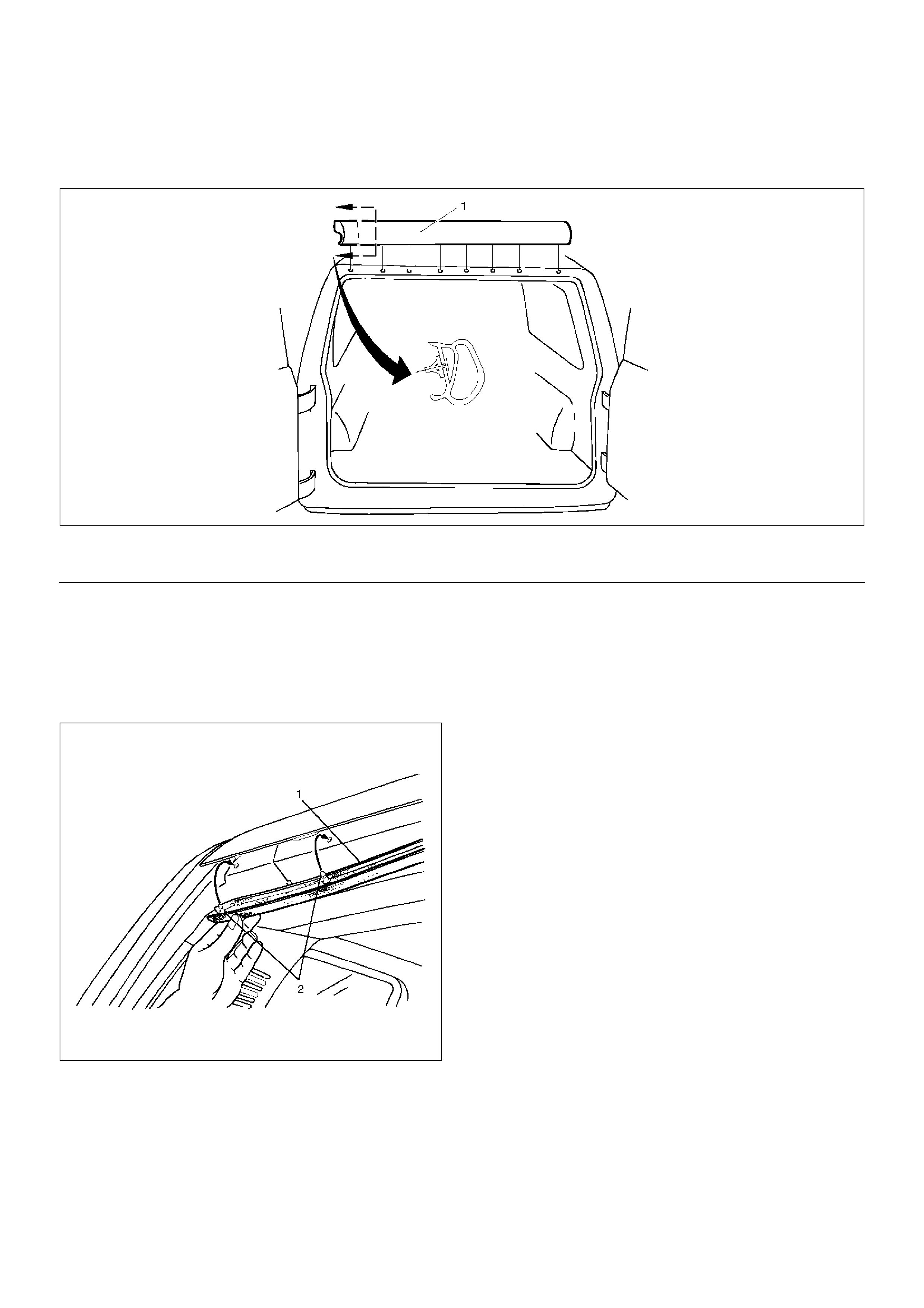
Tailgate Frame Cover (LH)
Parts Location
684RW001
EndOFCallout
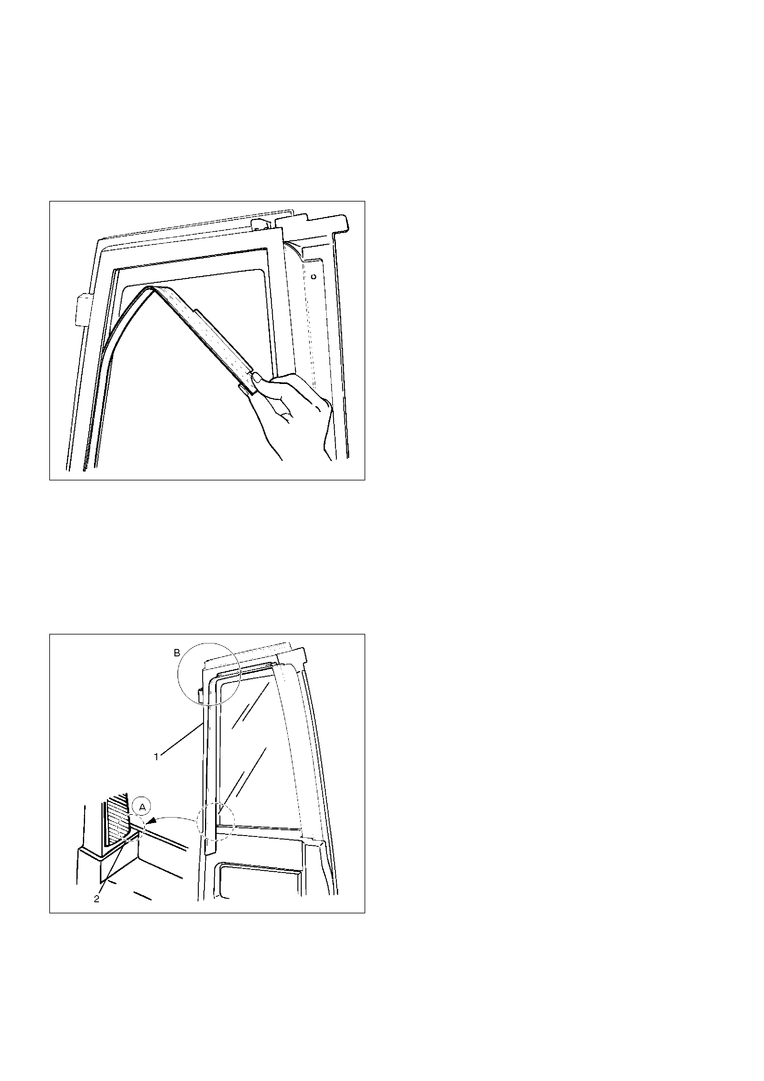
Removal
1. Disconnect the battery ground cable.
2. Remove tailgate frame cover.
• Pull the tailgate frame cover (2) out.
• Disconnect the washer tube (1) at the nozzle and
pull the washer tube out from the frame cover (2).
• Disconnect the rear defogger and pull the
harness from the cover.
684RW002
Installation
To install, follow the removal steps in the reverse order,
noting the following points.
1. Hit the lower A edge portion of the cover (1) to the
tailgate flange.
2. Clearance between the frame cover and the tailgate
panel (B portion) is 1 mm (0.04 in).
684RS008
Legend
(1) High Mount Stop Light
(2) Washer Tube
(3) Tailgate Frame Cover
Tailgate Frame Cover (RH)
Removal
1. Remove tailgate frame cover (RH).
• Pull the frame cover out from the tailgate frame.
684RS011
Installation
To install, follow the removal steps in the reverse order,
noting the following points.
1. Hit the lower A edge portion (2) of the tailgate frame
cover (1).
2. Clearance between the frame cover and the tailgate
panel (B portion) is 1 mm (0.04 in).
684RS010
Tailgate Sash Trim Cover
Parts Location
684RS012
Removal
1. Remove tailgate sash trim cover (1).
• Pry the tailgate trim cover retainers free from the
tailgate panel.
684RS013
Installation
1. Install the tailgate sash trim cover (1).
• Insert the trim cover retainers into the tailgate
hole securely so that there are no gaps between
them.
Legend
(1) Tailgate Sash Trim Cover
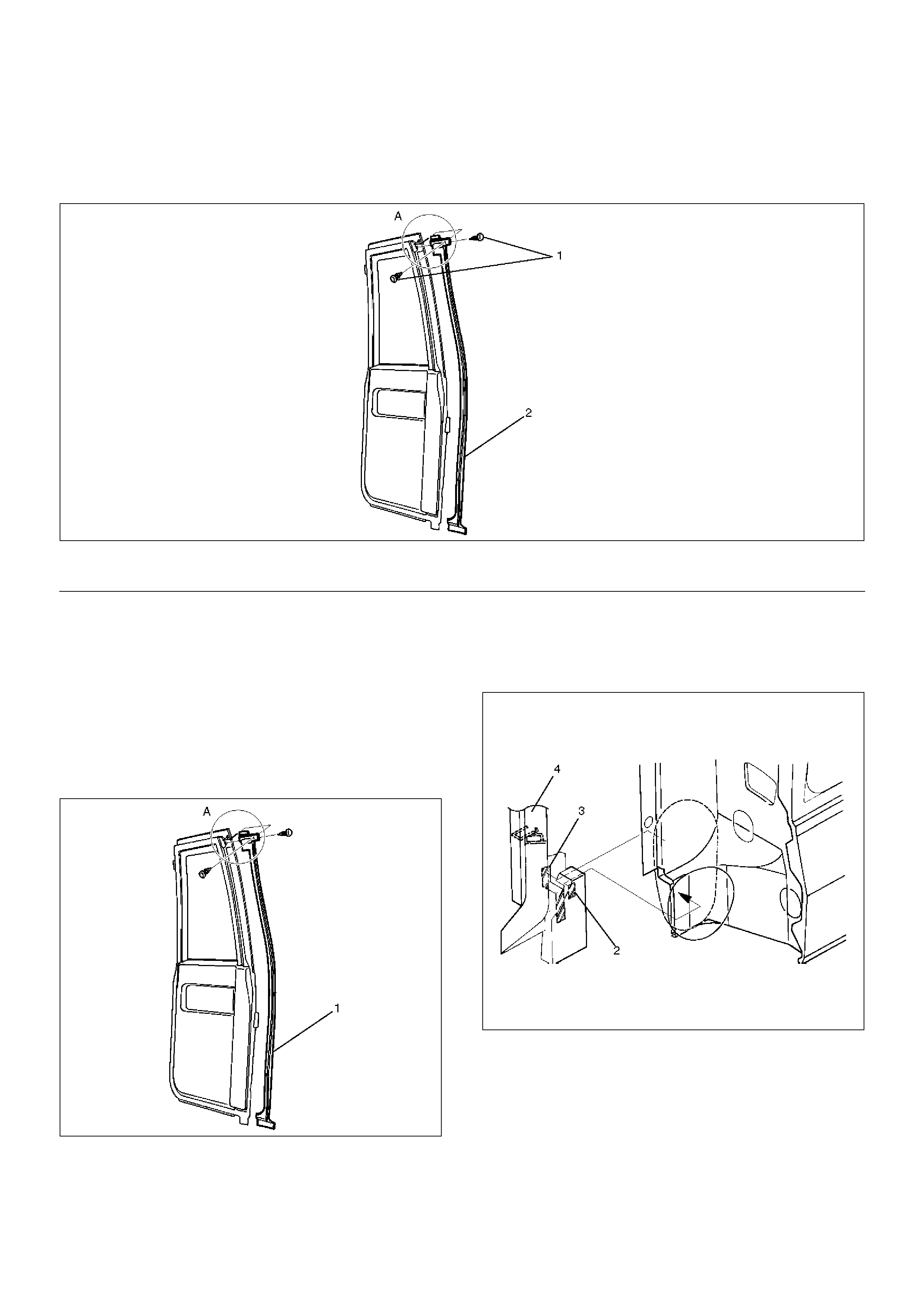
Tailgate Outer Weatherstrip
Parts Location
682RW001
Removal
1. Disconnect the battery ground cable.
2. Remove tailgate outer weatherstrip (1).
• Pry the tailgate outer weatherstrip clips (2) free
from the body panel.
682RS002
Installation
To install, follow the removal steps in the reverse order,
noting the following point.
1. Insert the tailgate outer weatherstrip clip into the
body panel hole securely in order to install the
tailgate outer weatherstrip with the gap between the
body panel and the weatherstrip.
Legend
(1) Tailgate Outer Weatherstrip
Tailgate Center Weatherstrip
Parts Location
682RS003
EndOFCallout
Removal
1. Remove tailgate center weatherstrip.
• Remove the fixing clips in order to pull the tailgate
center weatherstrip out from the tailgate panel.
Installation
1. Install the tailgate center weatherstrip (1).
• Start assembling at the A portion.
682RW006
• Clean the tailgate center weatherstrip (4)
adhesive tape (2) and the butyl seal (3) fitting
position of the tailgate panel.
• Affix new adhesive tape and the butyl seal to the
weatherstrip (lower side) in order to install the
tailgate center weatherstrip to the tailgate panel
with no gap between them.
682RS004
Legend
(1) Clip (2) Tailgate Center Weatherstrip
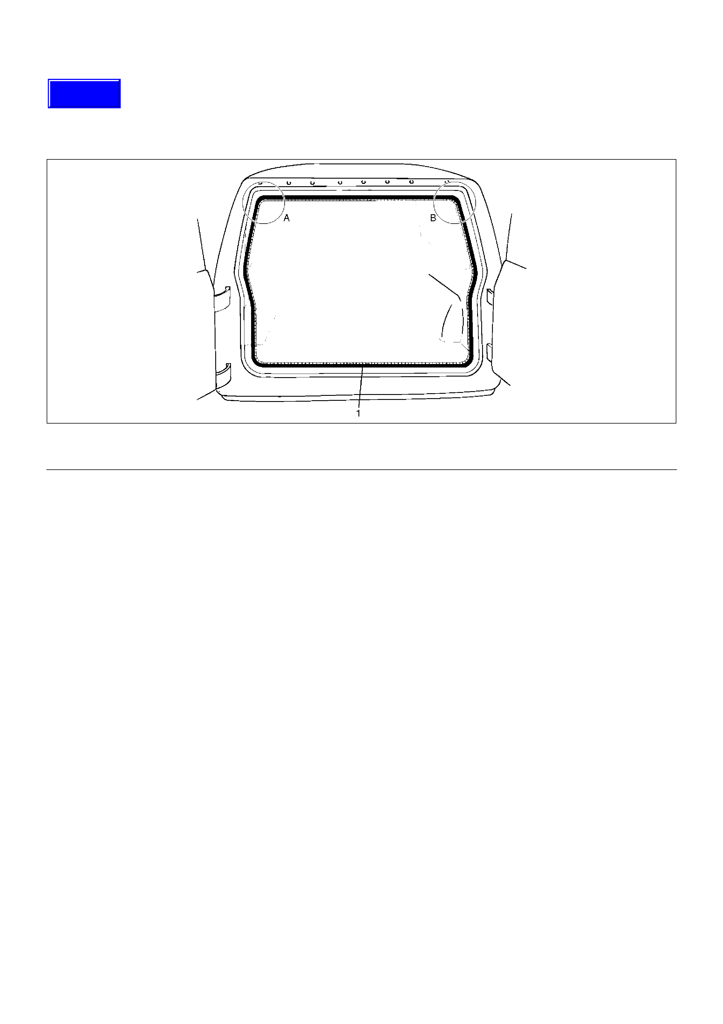
Tailgate Main Weatherstrip
Parts Location
682RS005
Removal
1. Remove tailgate main weatherstrip.
• Pull the tailgate main weatherstrip out from the
body panel.
Installation
1. Install the tailgate main weatherstrip.
• Align the A and B positions to the corners of the
body panel. Install the tailgate main weatherstrip
to the body panel by gently tapping with a plastic
hammer. There should be not clearance between
the body panel the tailgate main weatherstrip.
Legend
(1) Tailgate Main Weatherstrip
Techline
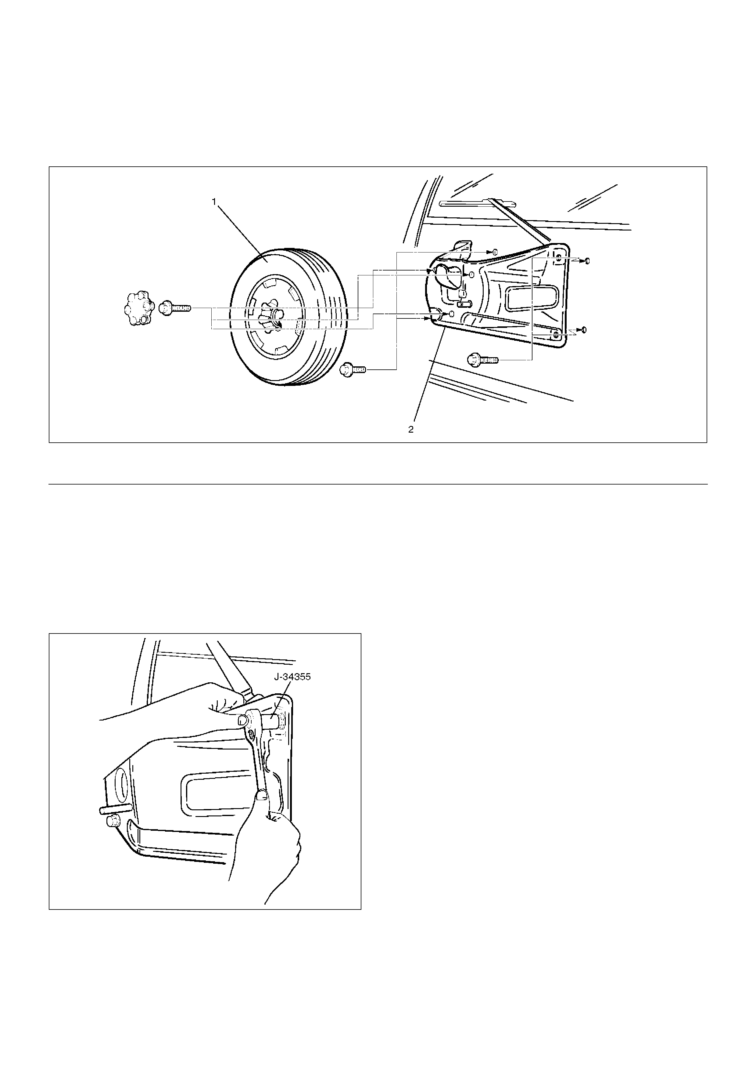
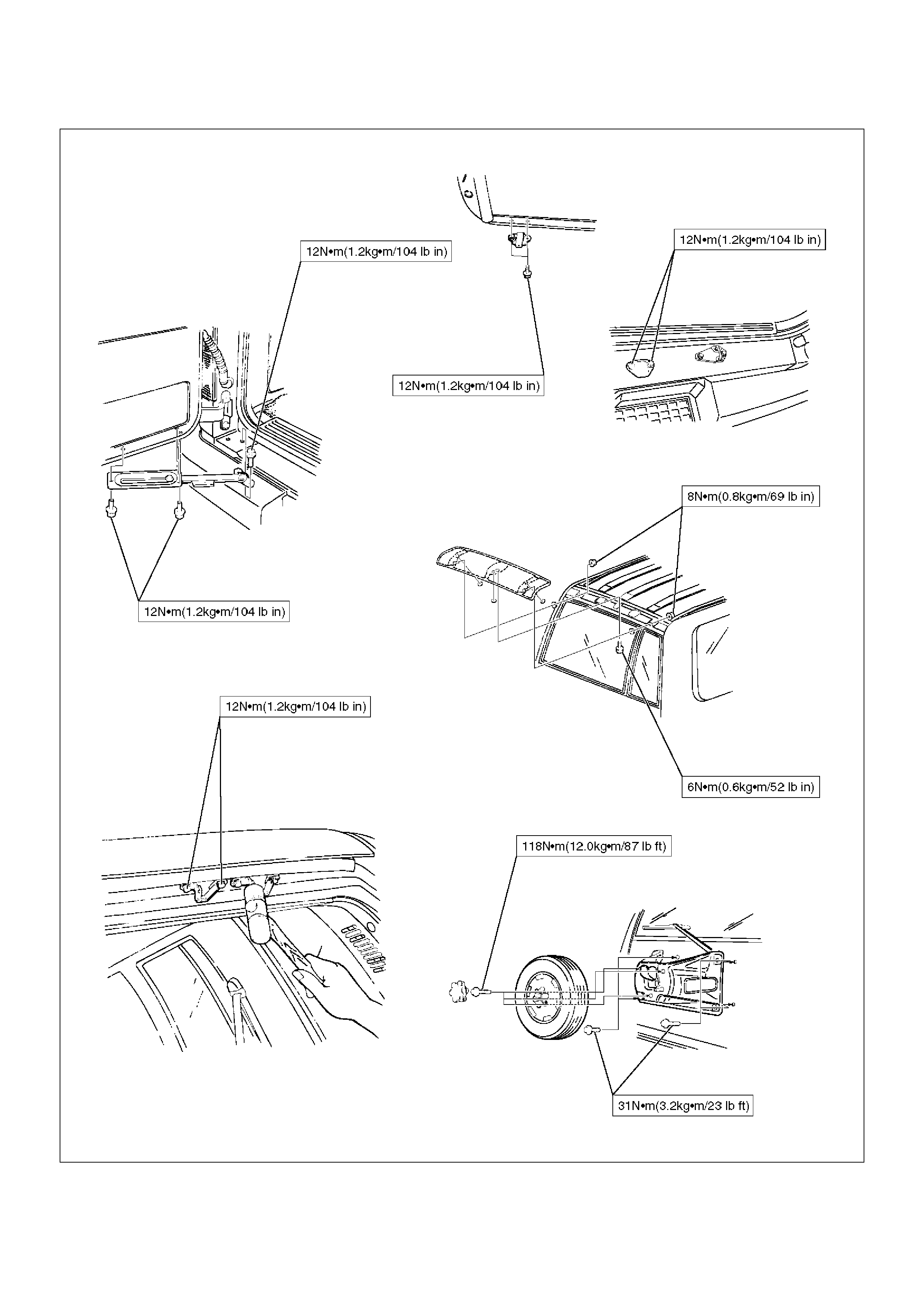
Spare Tire Carrier
Parts Location
530RS001
EndOFCallout
Removal
1. Remove spare tire.
2. Remove spare tire carrier.
• Remove the special bolts by using special tool (If
so equipped).
• Spare tire carrier bolt wrench 5–8840–2095–0 (J–
34355).
530RS002
Installation
1. Install the spare tire carrier.
• Tighten the carrier fixing bolts to the specified
torque.
Torque : 31N•m (3.2kg·m/23 lbft)
2. Install the spare tire.
• Tighten the spare tire fixing bolts to the specified
torque.
Torque : 118N•m (12.0kg·m/87 lbft)
Legend
(1) Spare Tire (2) Spare Tire Carrier
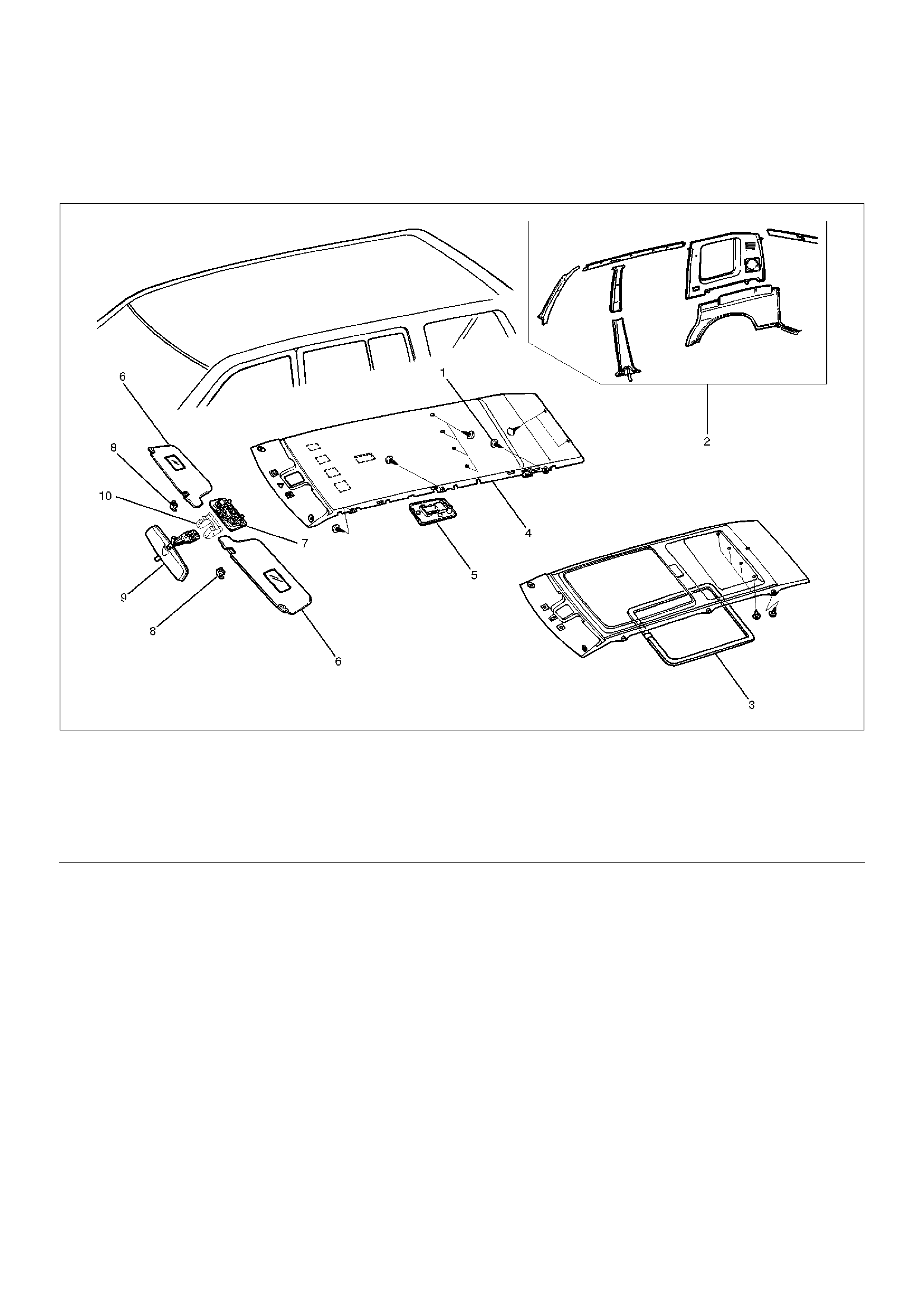
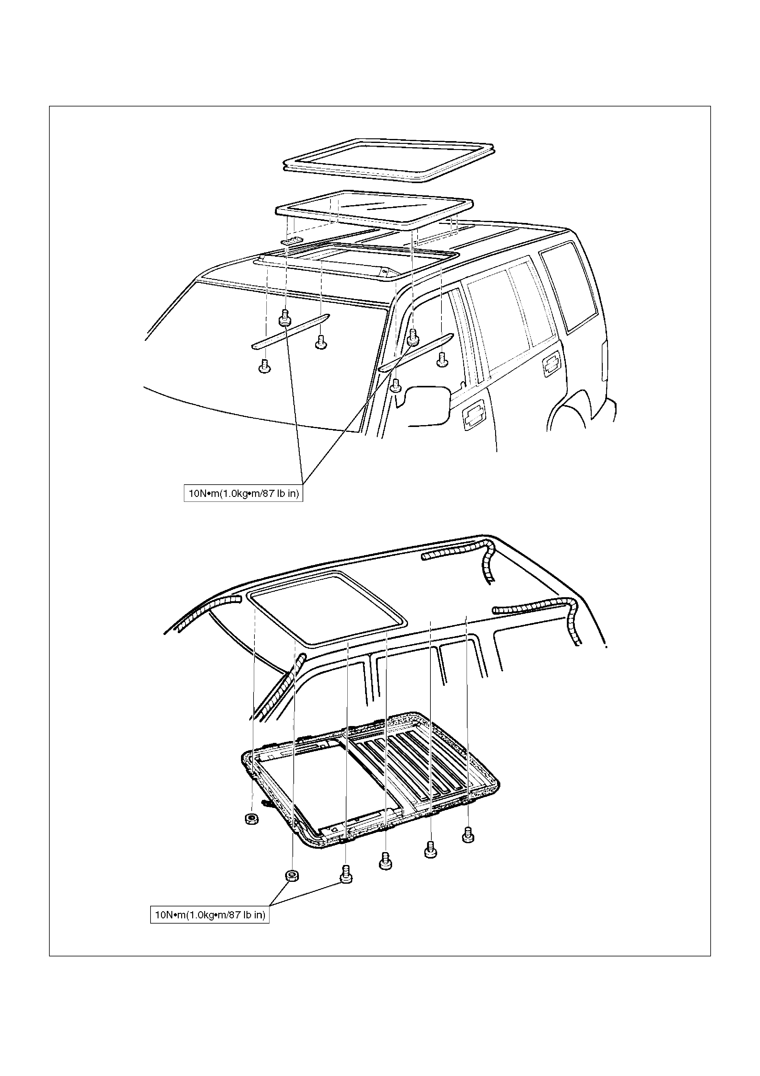
Headlining
Parts Location
666RW003
EndOFCallout
Removal
1.Disconnect the battery ground cable.
2.Remove interior trim panels.
•Refer to the Exterior / Interior Trim section.
3. Remove dome light.
• Remove the dome light lens and the fixing
screws.
• Disconnect the dome light connectors.
Legend
(1) Clip
(2) Interior Trim Panels
(3) Sun Roof Finisher (W/Sun Roof)
(4) Headlining
(5) Dome Light
(6) Sunvisors
(7) Map Light
(8) Sunvisor Holder
(9) Rear View Mirror
(10) Multi Meter
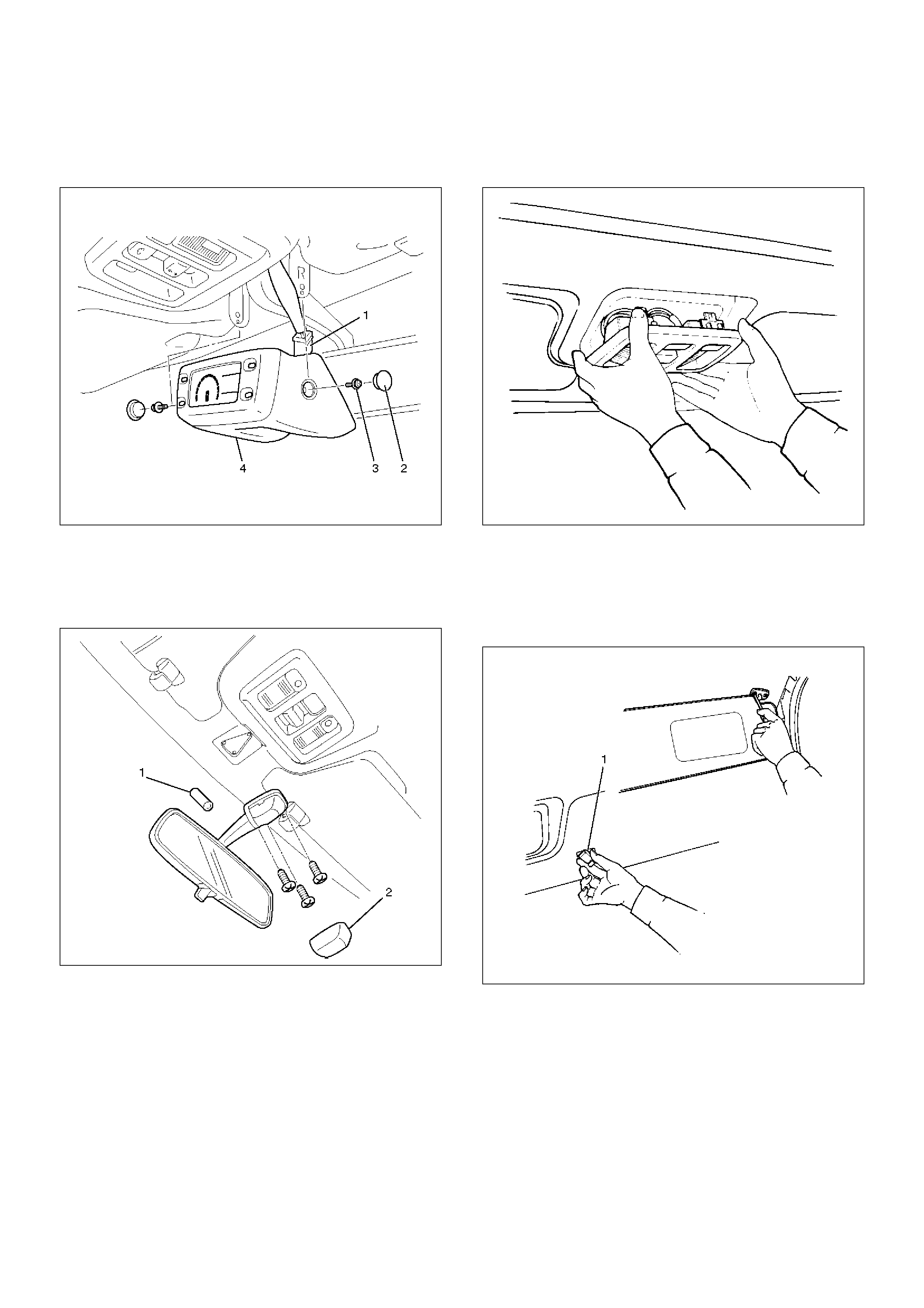
4. Remove multi meter (4) (If so equipped).
• Remove two caps (2), two screws (3) and
disconnect the connector (1).
821RW241
5. Remove rear view mirror.
• Remove the rubber stopper (1).
• Pry off the mirror stay cover (2) and remove 3
screws.
720RW004
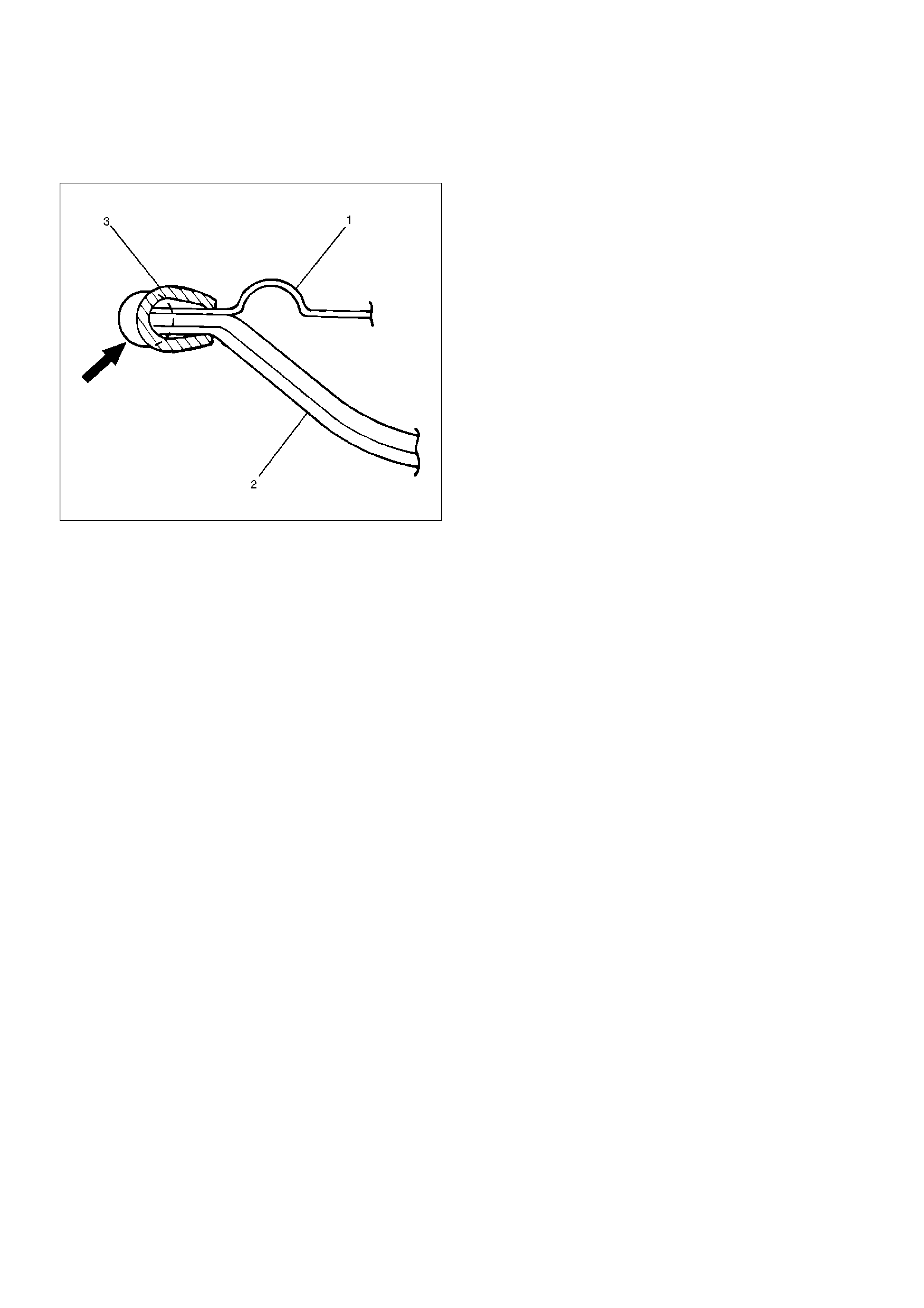
6. Remove map light/sun roof switch.
• Pry the map light clip free from the map light/sun
roof switch bracket and disconnect the connector.
805RS001
7. Remove sunvisors.
• Remove the fixing screw and turn the sunvisor
holder (1) to remove it.
• Disconnect the vanity mirror illumination
connector.
743RW008
8. Remove sun roof finisher (W/Sun roof).
9. Remove headlining.
• Remove the headlining fixing clips.
Installation
To install, follow the removal steps in the reverse order,
noting the following points.
1. Install the headlining so that the fixing clips will not
come off.
2. To install the sun roof finisher (3), first fit in at one
place with the head lining (2) close to the sun roof
frame complete (1), then install the entire finisher
tightly by hitting it with a plastic hammer, not
allowing it to move up.
665RS001
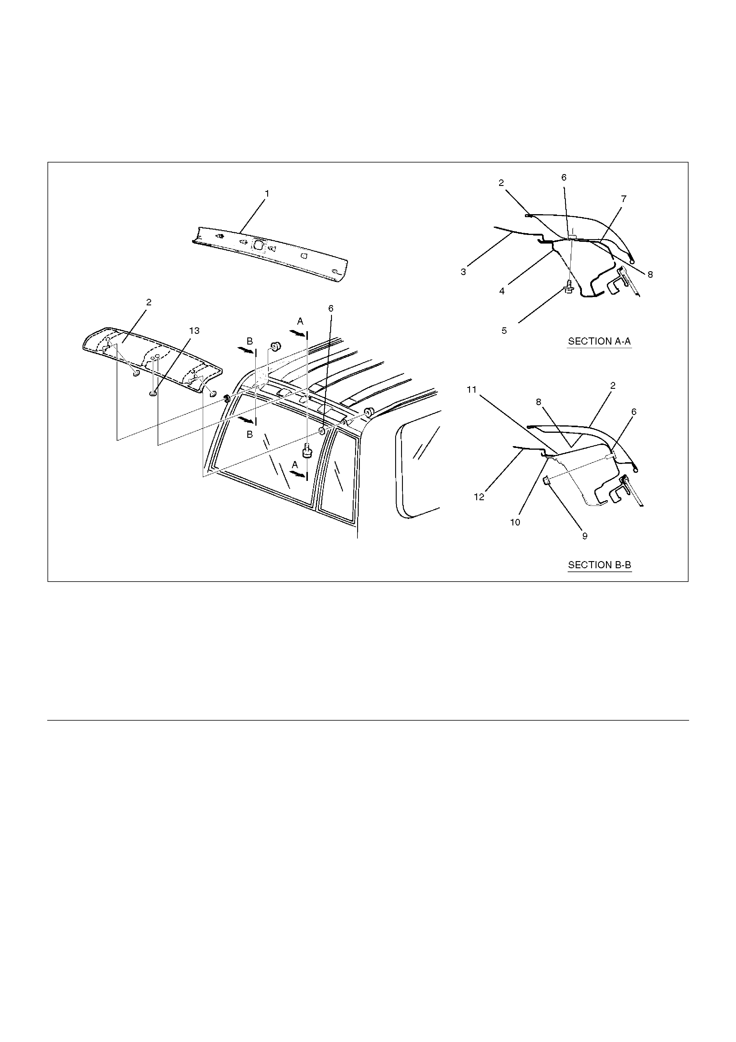
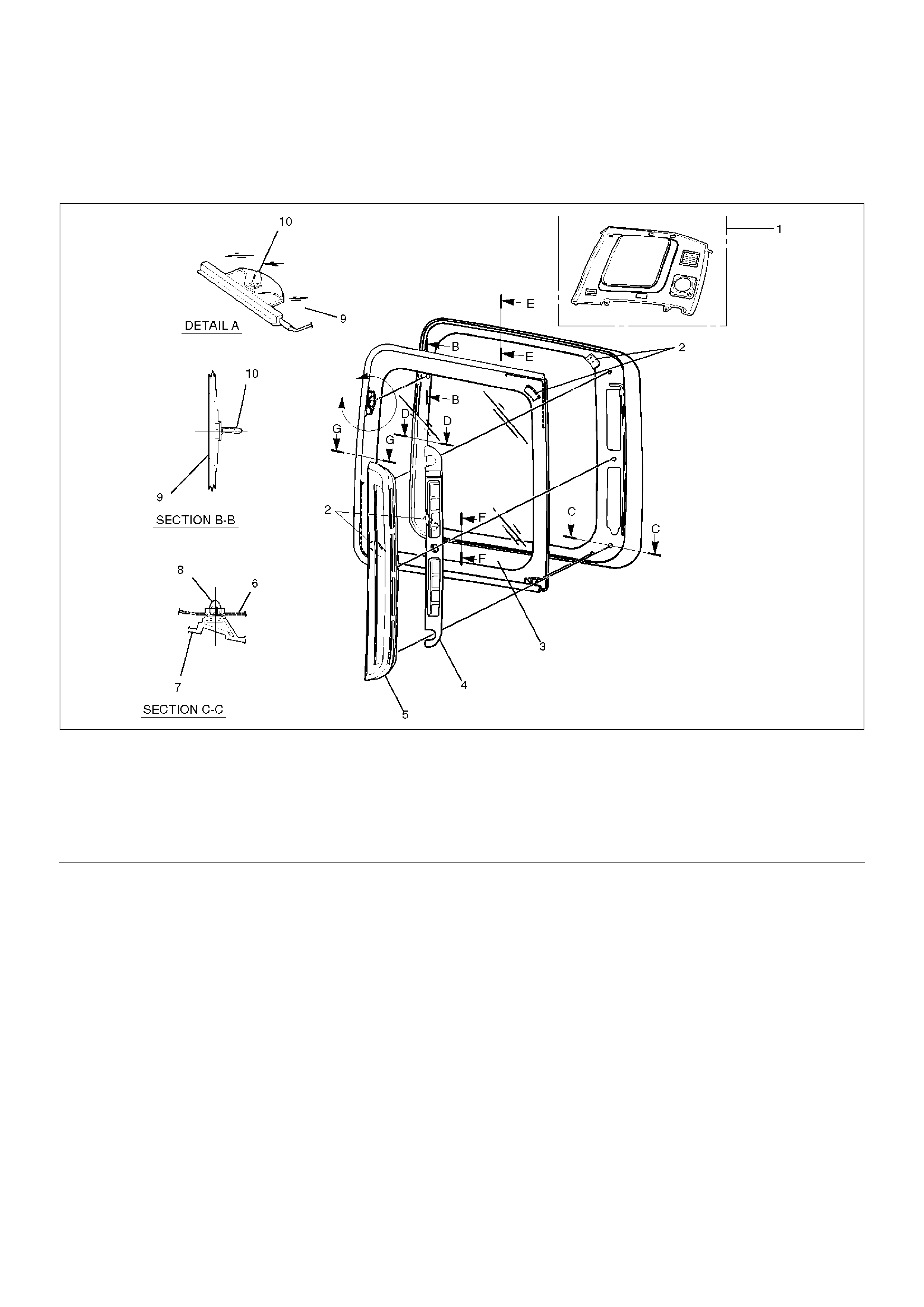
Rear Air Deflector
Parts Location
667RW001
EndOFCallout
Removal
1.Disconnect the battery ground cable
2.Remove rear roof trim cover.
•Refer to Luggage Side and Quarter Upper Trim
Cover in Exterior / Interior section.
3. Remove rear air deflector.
• Take notice of the grommet and the nylon
washer.
Legend
(1) Rear Roof Trim Cover
(2) Rear Air Deflector
(3) Roof Rail
(4) Rear Inner Roof Rail
(5) Fixing Bolt
(6) Nylon Washer
(7) Rear Outer Roof Panel
(8) Grommet
(9) Fixing Nut
(10) Rear Pillar Upper Reinforcement
(11) Rear Outer Roof Rail
(12) Roof Panel
(13) Grommet
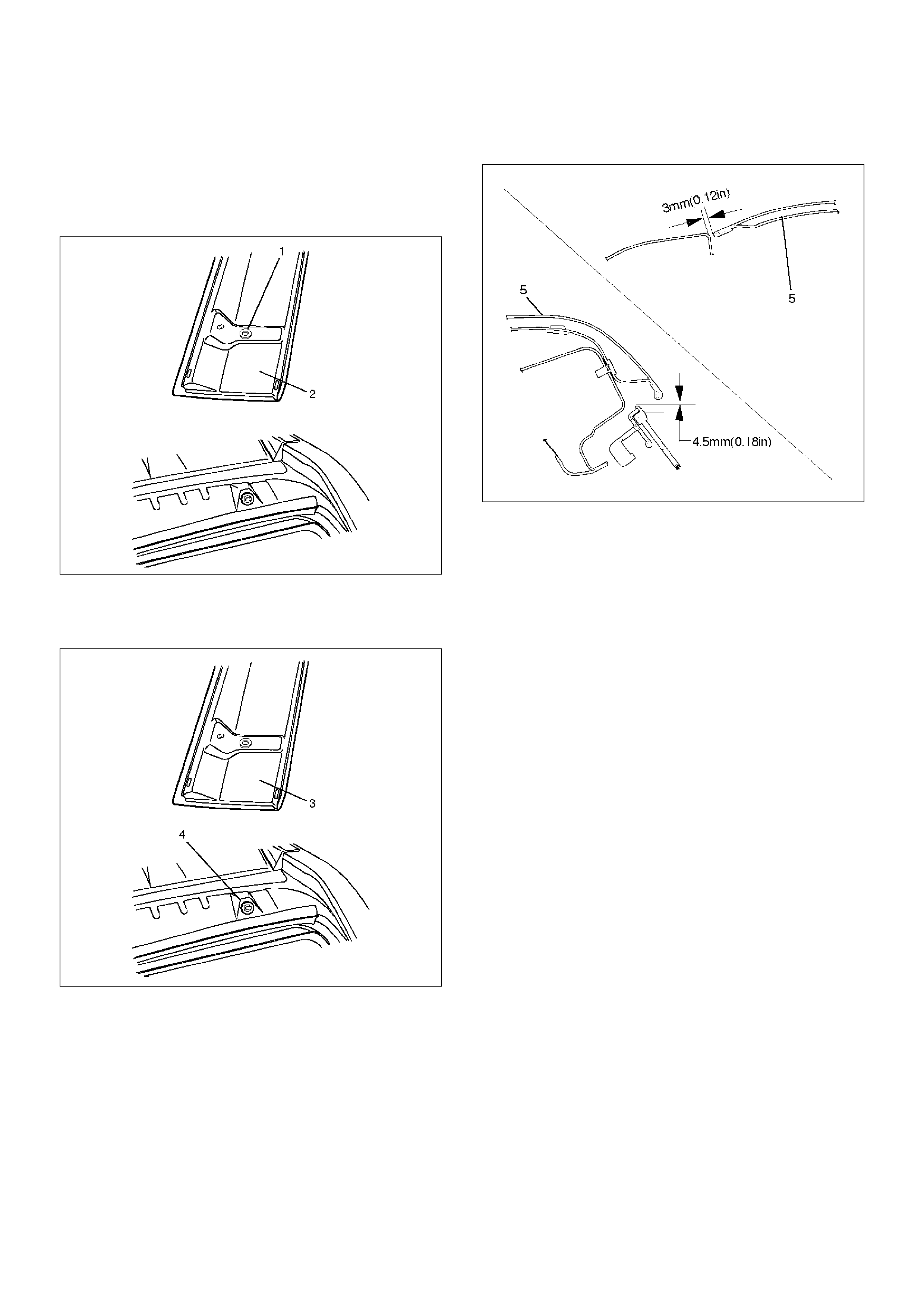
Installation
To install, follow the removal steps in the reverse order,
noting the following points.
1. Install the grommet (1) to the air deflector (2) drain
hole.
667RW002
2. Use a new nylon washer (4). Peel off the adhesive
tape of the washer to install the nylon washer to the
air deflector (3).
667RW004
3. Install the air deflector (5) to the roof by referring to
the specified values shown in the illustration.
667RW003
4. Tighten the deflector fixing to the specified torque.
Bolt Torque : 6N•m (0.6kg·m/52 lbin)
Nut Torque : 8N•m (0.8kg·m/69 lbin)
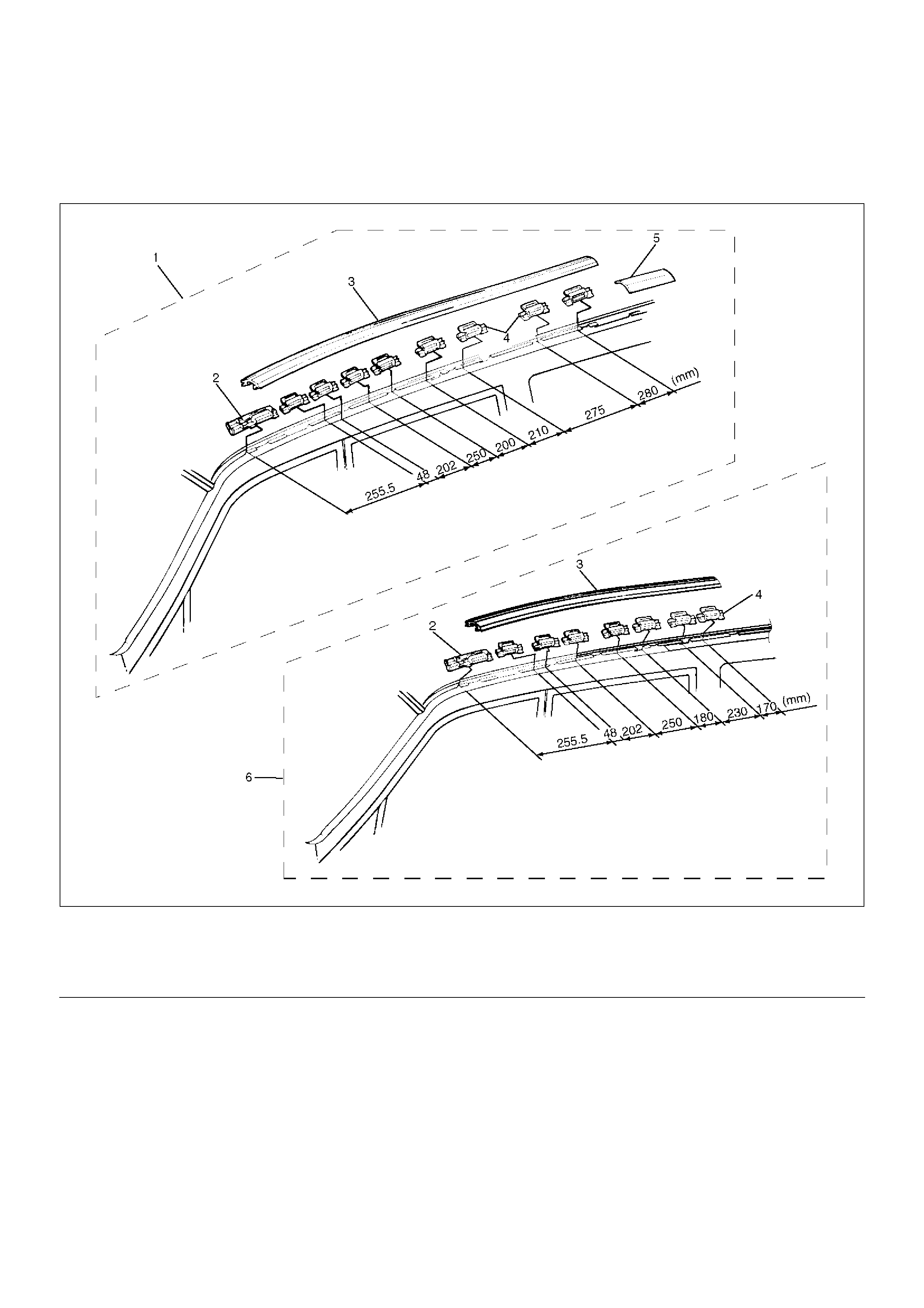
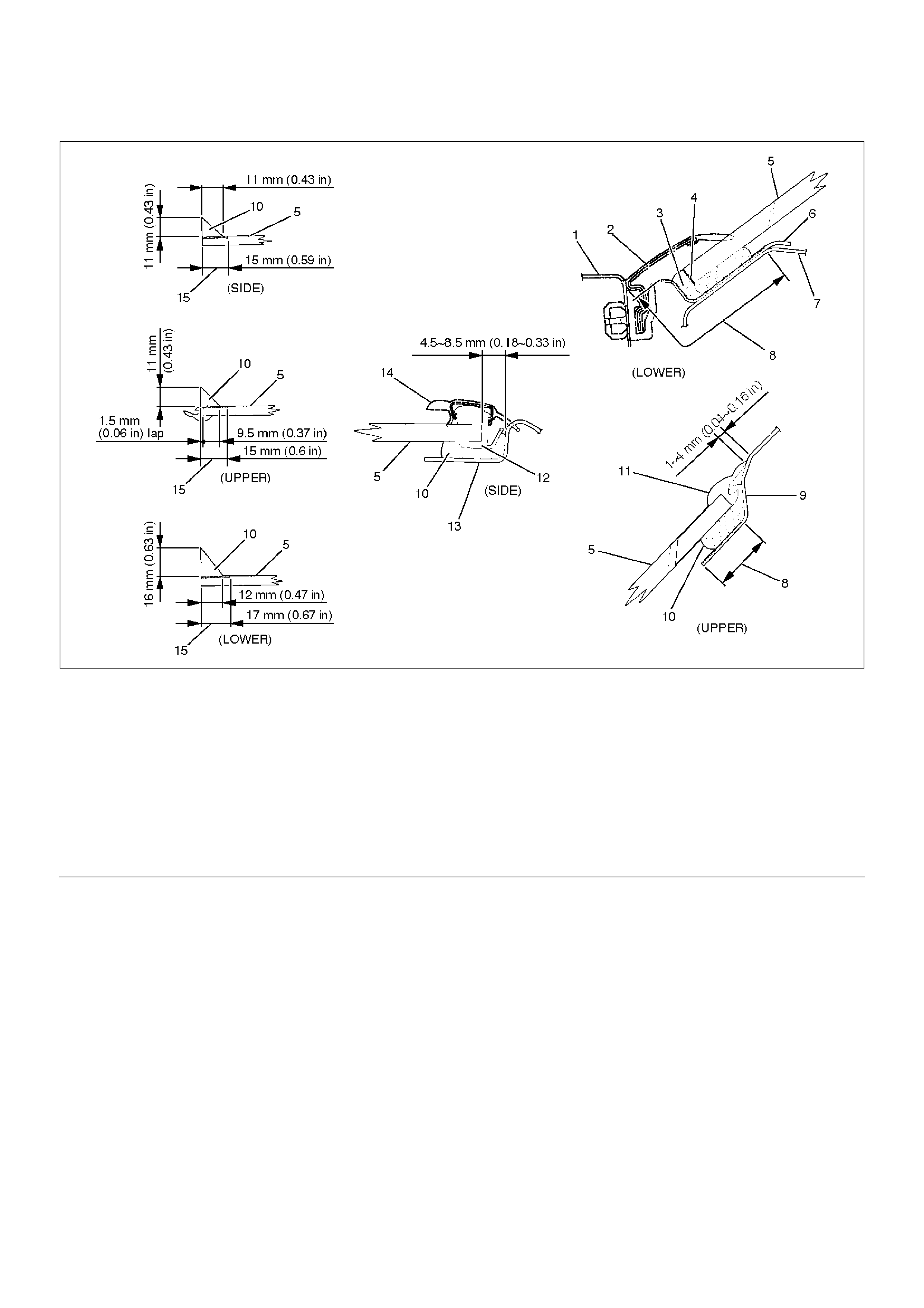
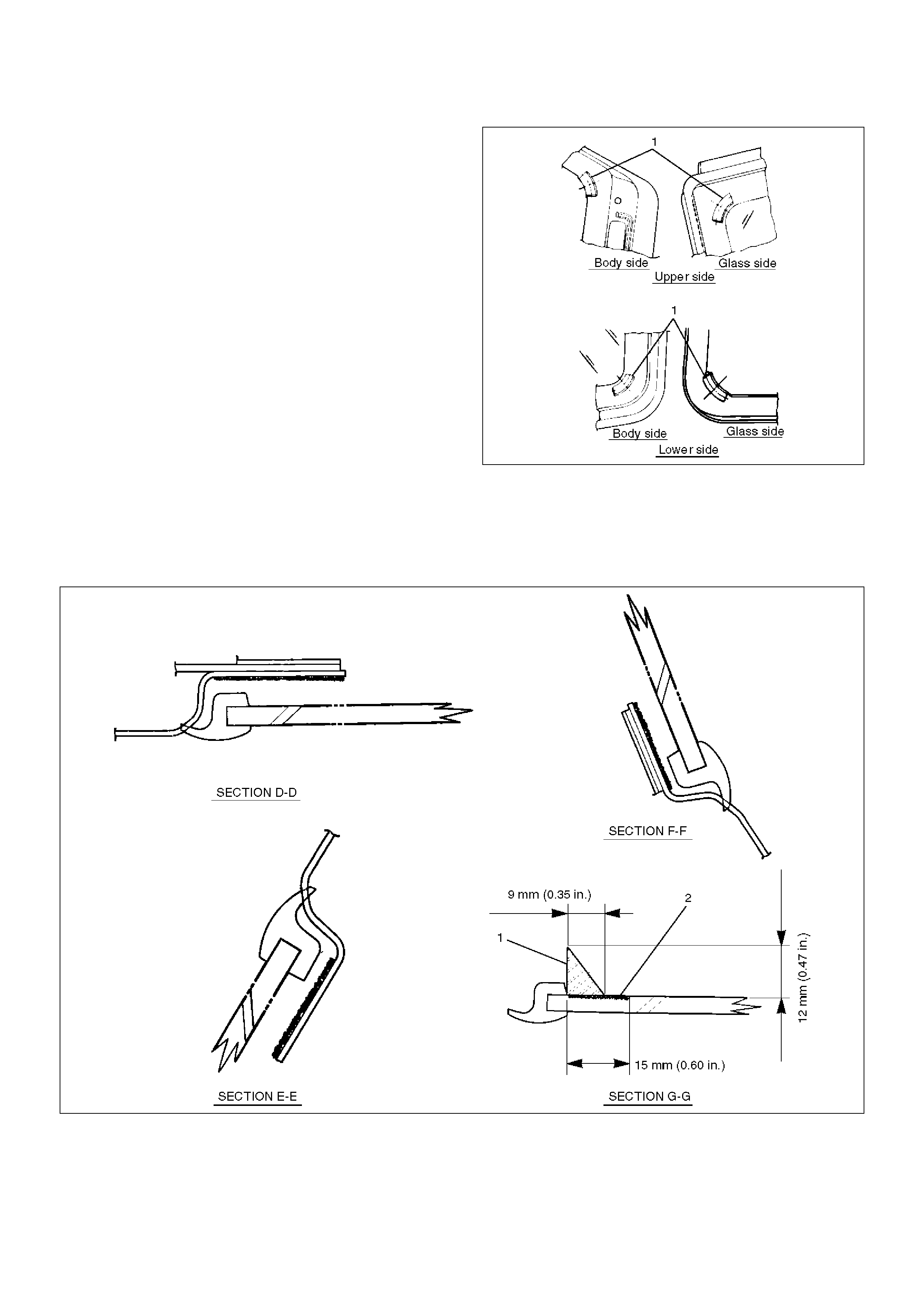
Roof Moulding
Parts Location
645RW009
EndOFCallout
Removal
1. Disconnect the battery ground cable.
2. Remove roof moulding.
3. Remove roof end moulding.
• Remove the sealing adhesive and the adhesive
tape of the roof end moulding from the panel
using a knife or scraper while you peel them off.
4. Remove roof moulding clips.
Legend
(1) L·W·B
(2) Windshield Side Moulding Upper Clip
(3) Roof Moulding
(4) Roof Moulding Clip
(5) Roof End Moulding
(6) S·W·B
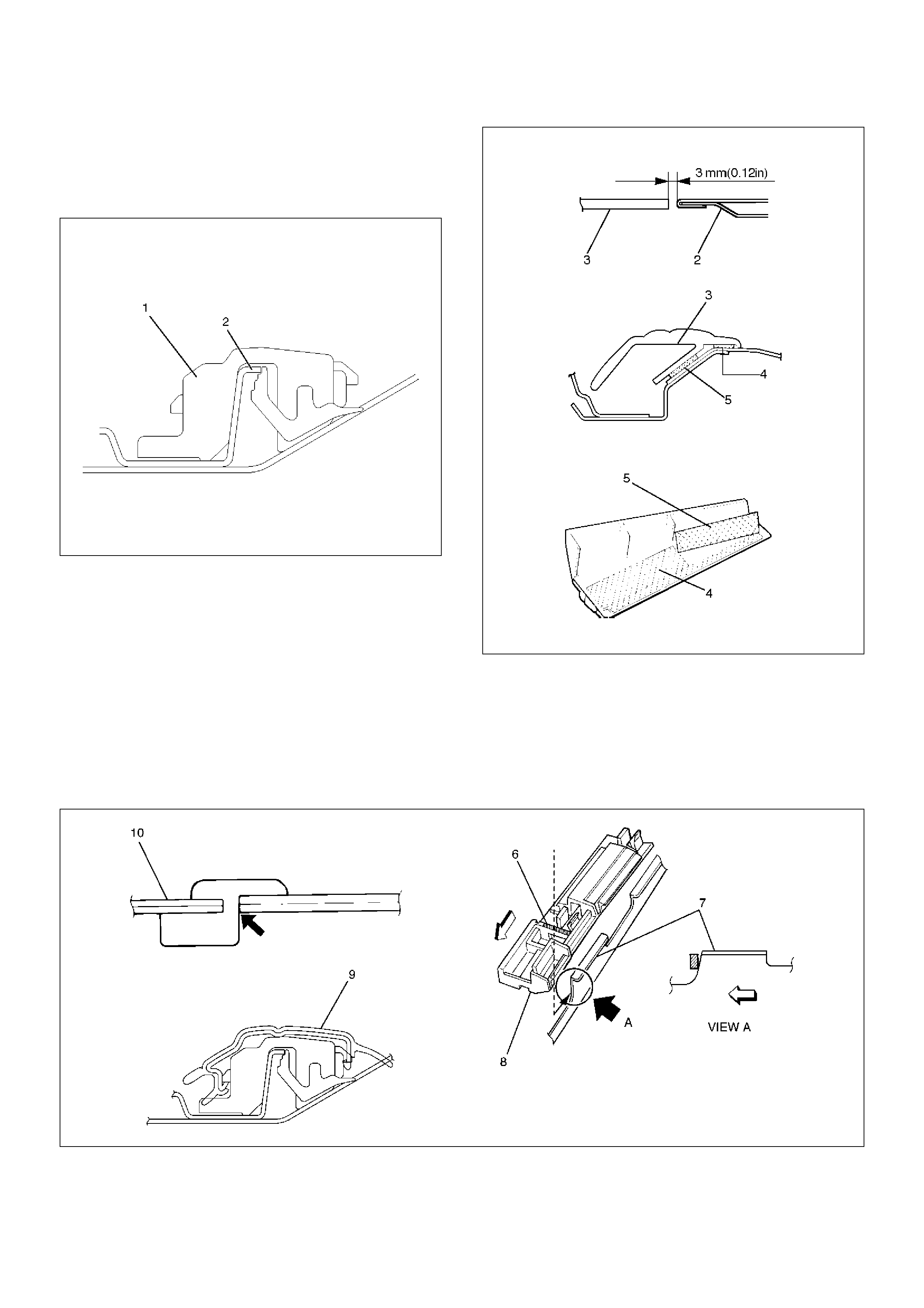
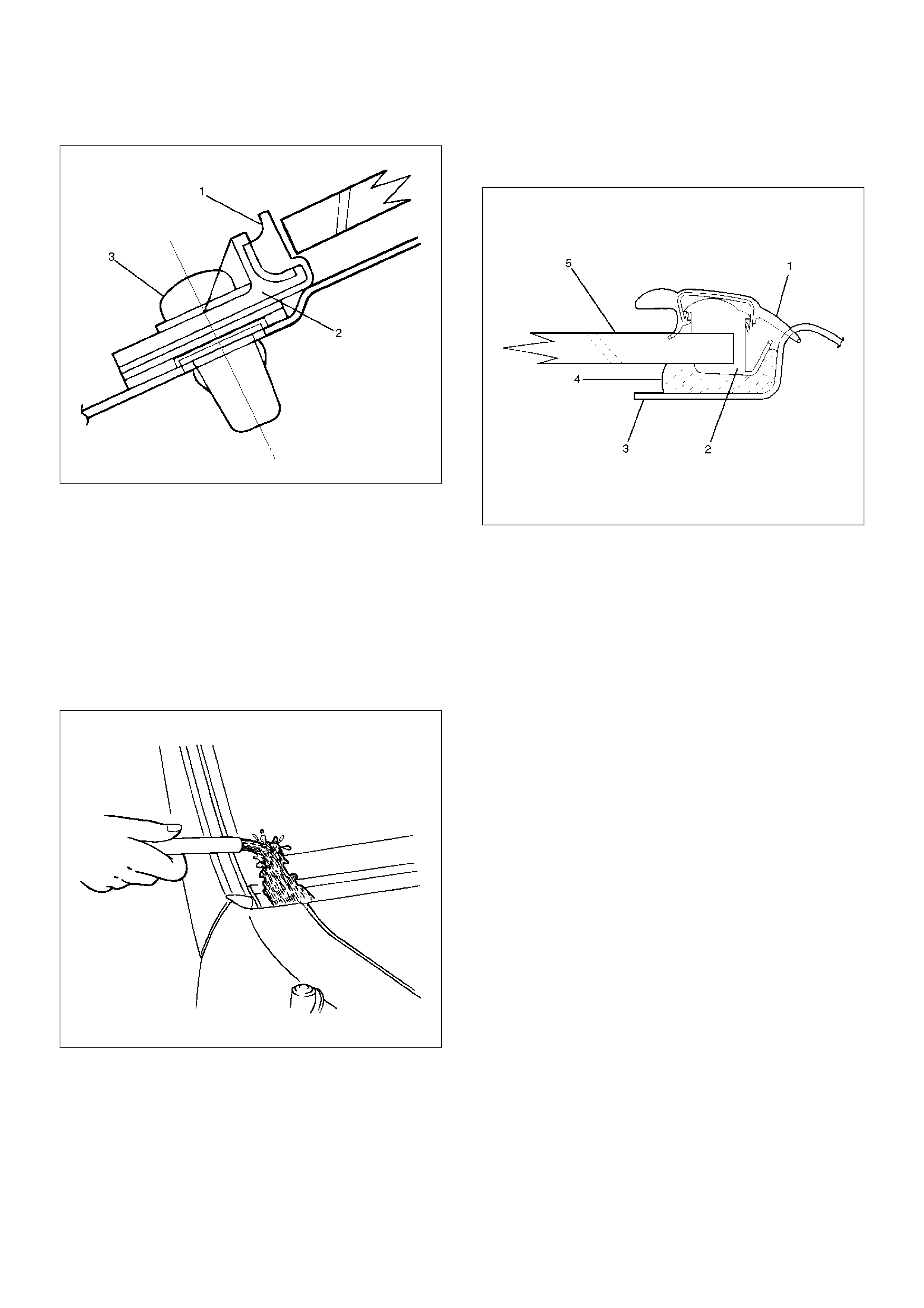
Installation
1. Install the moulding roof clips (1).
• Install the clips on roof panel flange (2) to refer
the illustration.
645RW003
2. Install the roof end moulding (3).
• Clean the body panel where the roof end
moulding is installed.
• Install the roof end moulding and the rear air
deflector (2) so that the installation clearance
between them is within the specified values.
Securely fix it with the adhesive tape (4) and
sealing adhesive (5).
645RW001
3. Install the roof moulding (9).
• Assemble the windshield side moulding upper
clip (8) to the roof panel with the clip positioning
rib (6) (oblique lines portion) attached to the roof
panel flange (7). Assemble the roof moulding (9)
while you attach the front edge portion of the roof
molding to the windshield side moulding (10).
645RX001
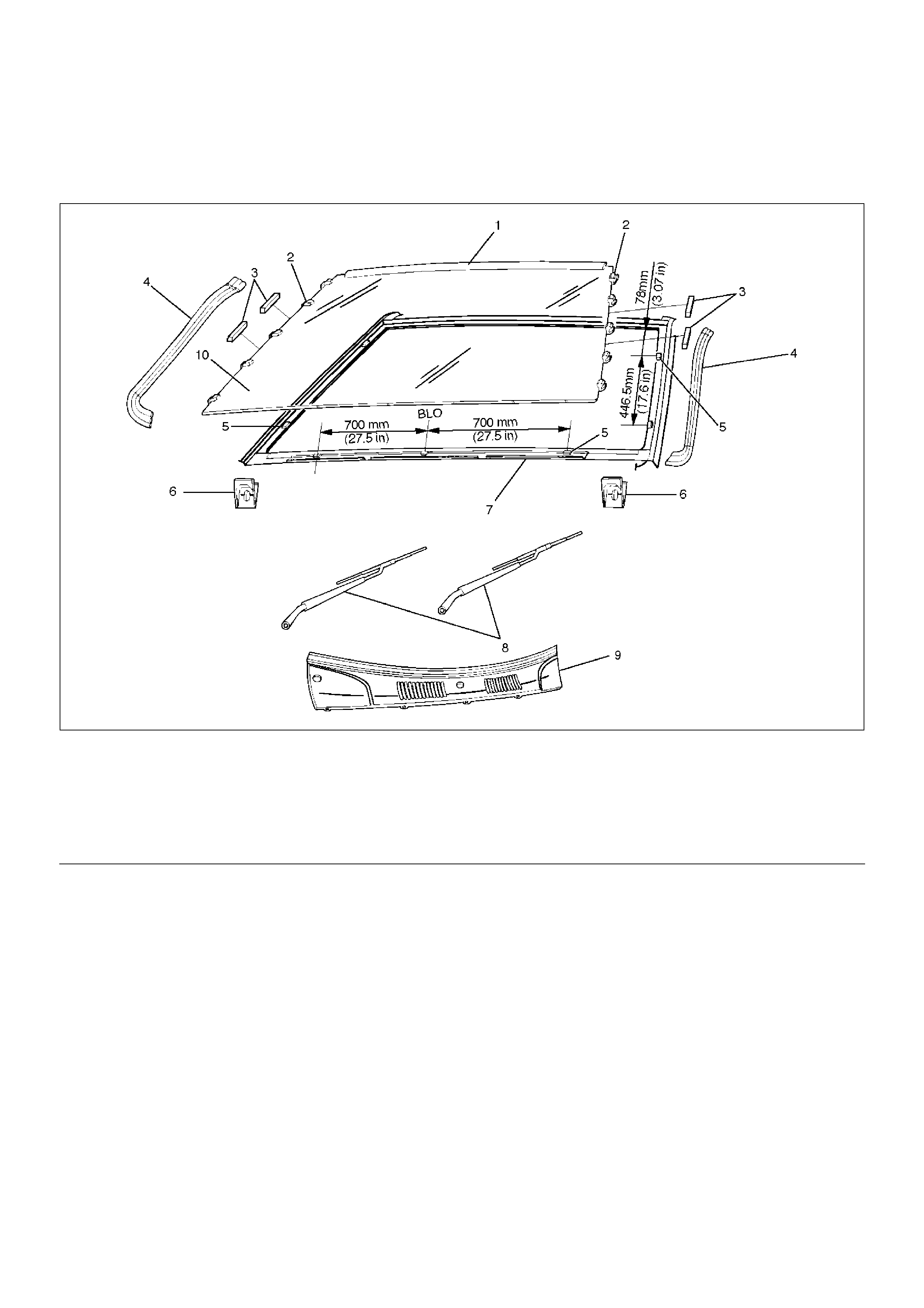
Windshield
Parts Location
607RW006
EndOFCallout
Removal
1.Disconnect the battery ground cable.
2.Remove windshield wiper.
•Refer to Windshield Wiper Arm/Blade in Wiper/
Washer System section.
3. Remove front cowl cover.
•Refer to Cowl Cover in this section.
4. Remove windshield side moulding.
• Pull the moulding out from the windshield side
moulding clip.
5. Remove windshield support.
6. Remove windshield side seal.
7. Remove windshield (2).
• Use a knife or pick to make a hole in part of the
adhesive caulking material.
Legend
(1) Windshield Upper Moulding
(2) Moulding Clip
(3) Windshield Side Seal
(4) Windshield Side Moulding
(5) Spacer
(6) Windshield Support
(7) Cowl Upper Rail Flange
(8) Windshield Wiper
(9) Front Cowl Cover
(10) Windshield
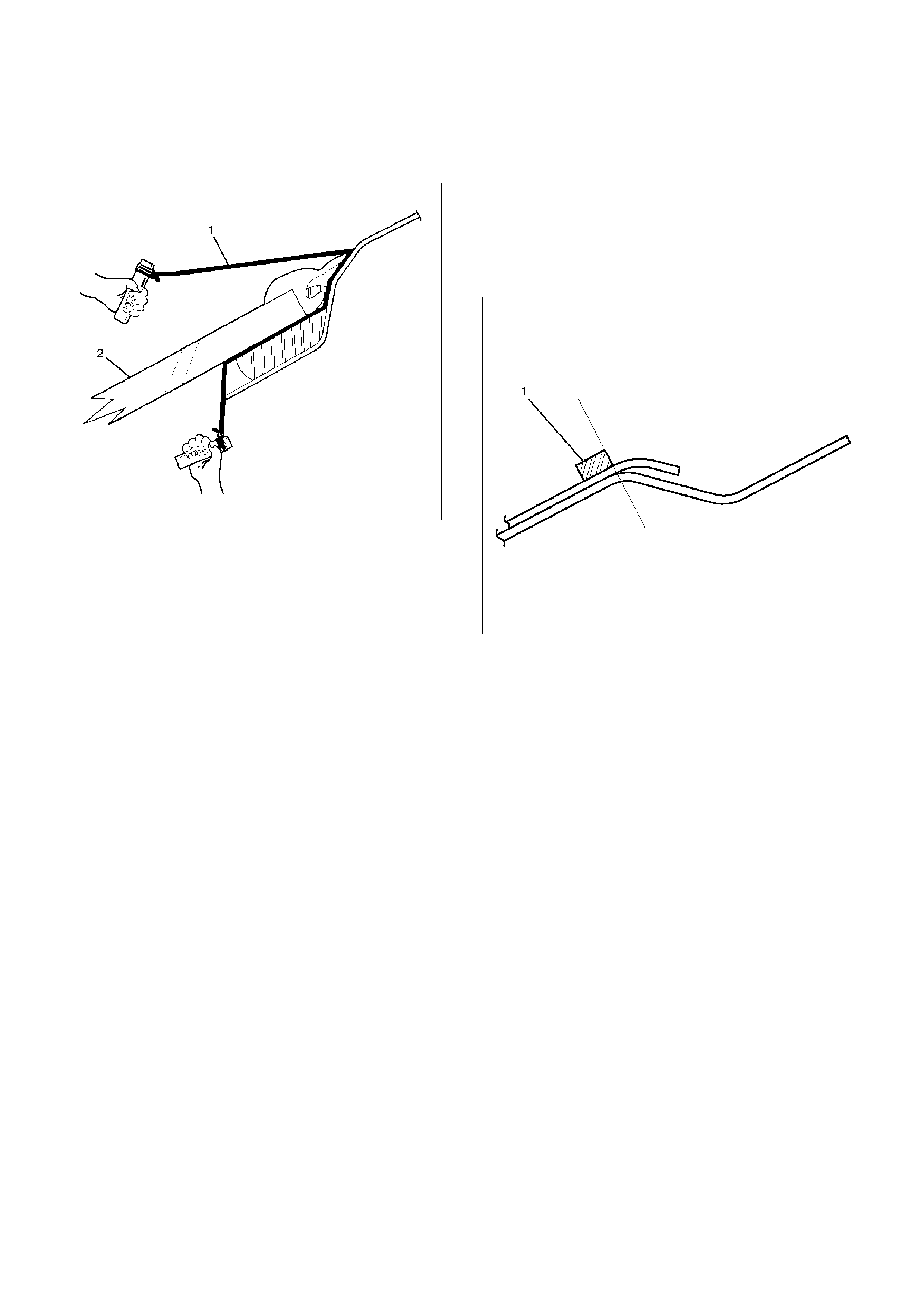
• Secure one end of a piece of steel piano wire (1)
(0.02 inches in diameter) to a piece of wood that can
serve as a handle.
607RS002
• Use a pair of needle nose pliers to insert the other
end of the piano wire through the adhesive caulking
material at the edge of the windshield glass.
• Secure the other end of the piano wire to another
piece of wood.
• With the aid of an assistant, carefully move the piano
wire with a sawing motion to cut through the adhesive
caulking material around the entire circumference of
the windshield glass.
• Clean the remaining adhesive caulking material from
the area of the body which holds the windshield.
8. Remove windshield upper moulding.
• Taking notice of the adhesive tape, and peel the
moulding off the windshield upper portion.
9. Remove moulding clip.
10. Remove spacer.
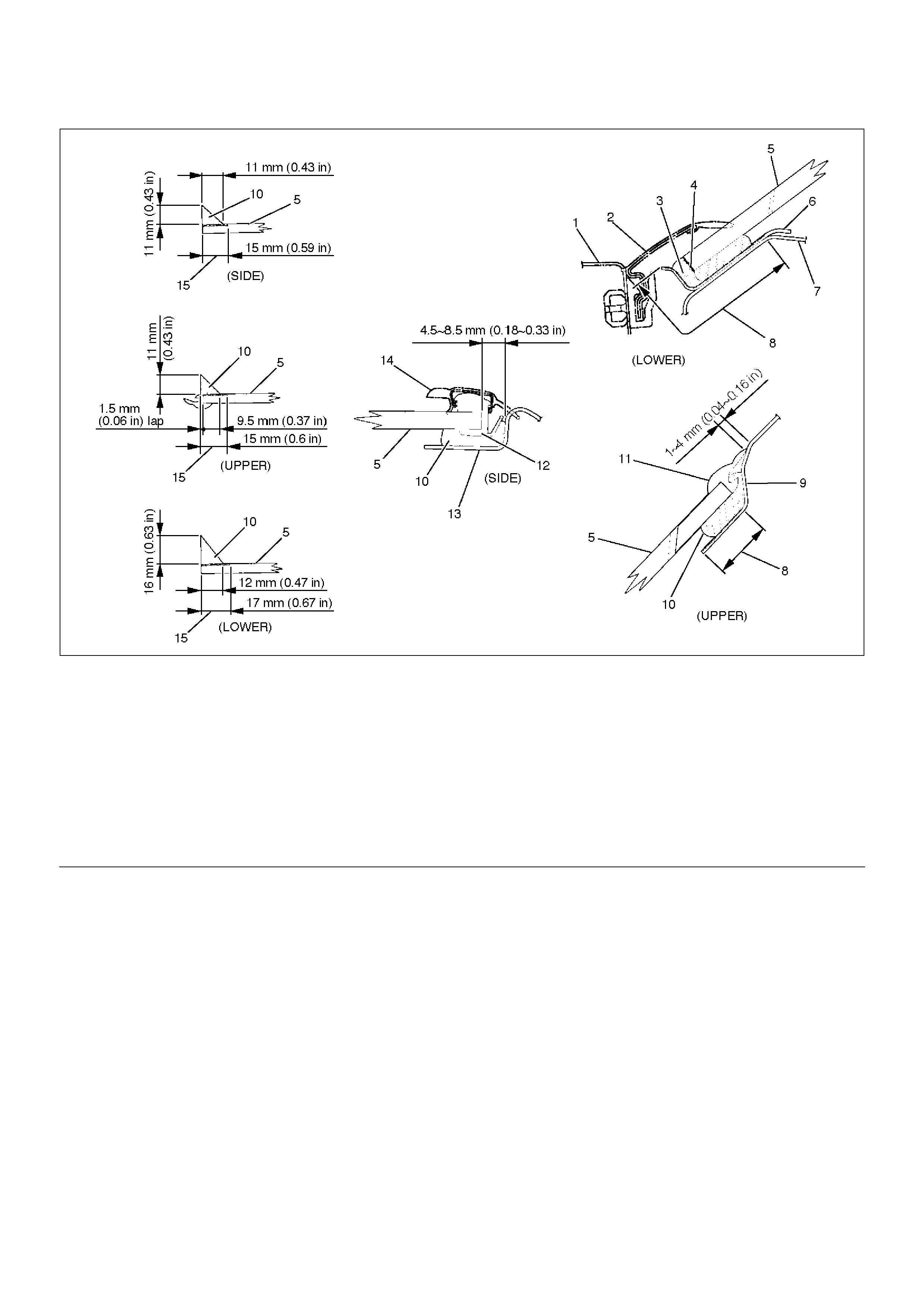
Installation
1. Install the spacer (1).
• Clean the bonding surfaces of both the
windshield and the body panel.
• When installing the spacers, align the lower side
spacer to the R stop of the body panel and the
side spacer to the end of the body panel. Be sure
to always use a new spacer.
607RS003
• Be absolutely sure to apply glass primer and
body primer to the body panel as shown in the
illustration.
607RW005
E n dO FC al lo ut
2. Install the moulding clip (2).
• Install new moulding clips to the fixed position of
the windshield (3).
Legend
(1) Front Cowl Cover
(2) Windshield Lower Moulding
(3) The portion of the cowl upper rail flange where
sealing adhesive is additionally filled
(4) Apply primer to the glass and portion where
sealing adhesive is additionally filled
(5) Windshield
(6) Cowl Upper Rail
(7) Cowl Upper Panel
(8) Body Primer
(9) Roof Panel
(10) Sealing Adhesive
(11) Windshield Upper Moulding
(12) Moulding Clip
(13) Front Pillar Outer Panel
(14) Windshield Side Moulding
(15) Sealing Adhesive
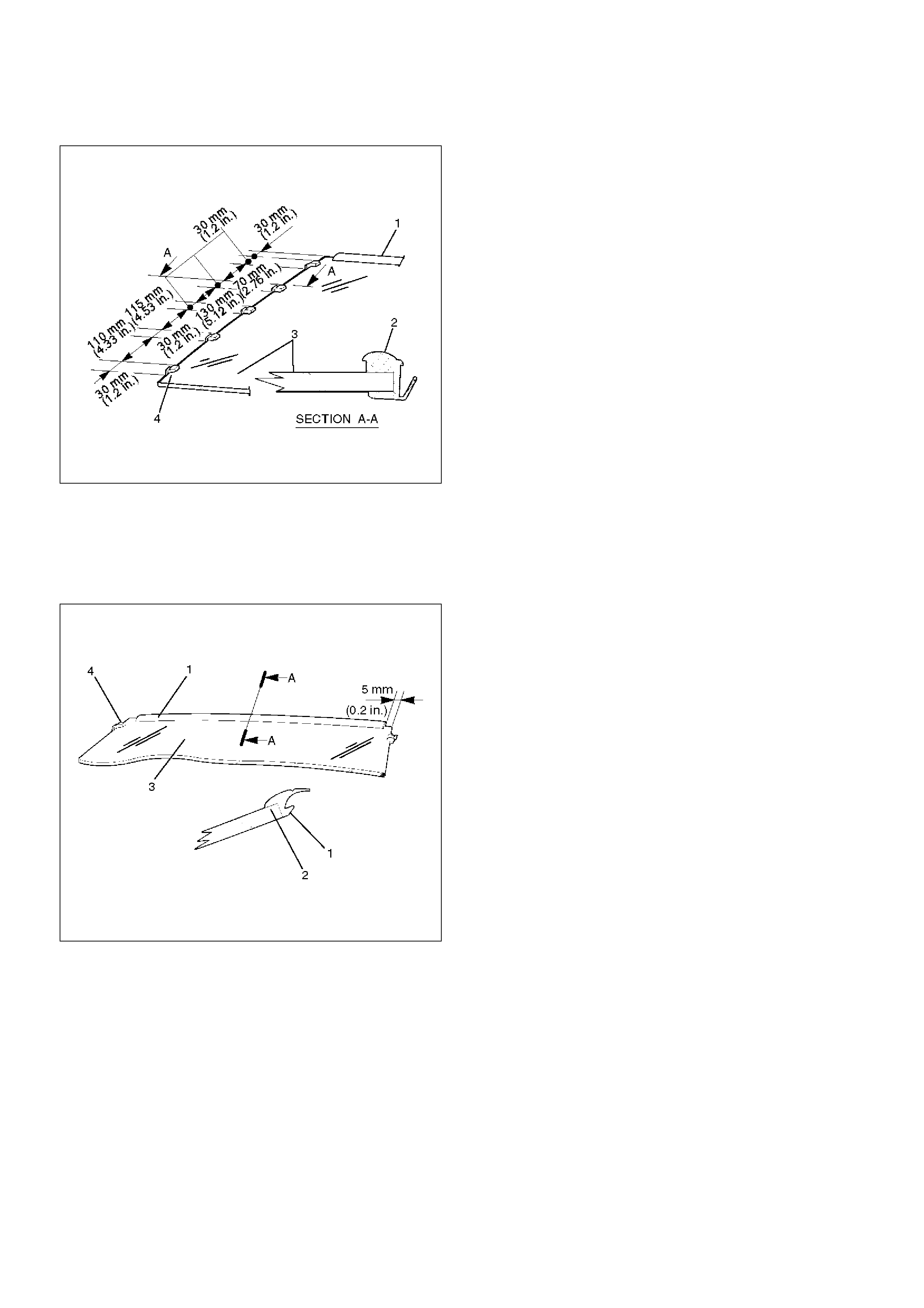
• Always use new moulding clips (4).
607RS004
3. Install the windshield upper moulding (1).
• Peel off the adhesive tape (2) and install the
moulding to the fixed position of the windshield
(3).
• Always use new upper moulding (1).
607RS005
4. Install the windshield.
607RW005
EndOFCallout
5. Install the windshield side seal.
Legend
(1) Front Cowl Cover
(2) Windshield Lower Moulding
(3) The portion of the cowl upper rail flange where
sealing adhesive is additionally filled
(4) Apply primer to the glass and portion where
sealing adhesive is additionally filled
(5) Windshield
(6) Cowl Upper Rail
(7) Cowl Upper Panel
(8) Body Primer
(9) Roof Panel
(10) Sealing Adhesive
(11) Windshield Upper Moulding
(12) Moulding Clip
(13) Front Pillar Outer Panel
(14) Windshield Side Moulding
(15) Sealing Adhesive
6. Install the windshield support (2).
631RS014
• Apply a sealing adhesive to the circumference of
the windshield.
• Apply the sealing adhesive to the frange portion
of the cowl upper rail.
• Adjust the gap clearance of the windshield.
• Install the windshield to the body panel by
applying pressure to the windshield.
• Cure the adhesive at a temperature of 20~30°C
(68~86°F) for 24 hours.
• Check that the windshield does not leak water.
607RS007
7. Install the windshield side moulding.
• Insert the windshield (5) side moulding (1) into
the moulding clip (2).
607RS008
• Take care not to damage the side moulding when
you install it.
8. Install the front cowl cover.
9. Install the windshield wiper.
Rear Quarter Side Glass
Parts Location
641RS005
EndOFCallout
Removal
1.Disconnect the battery ground cable.
2.Remove rear quarter upper trim panel.
•Refer to Laggage Side and Quarter Upper Trim
Cover in Exterior / Interior Trim section.
3. Remove ventilation assembly.
4. Remove valve assembly.
•Refer to Ventilation Assembly in Exterior / Interior
Trim section.
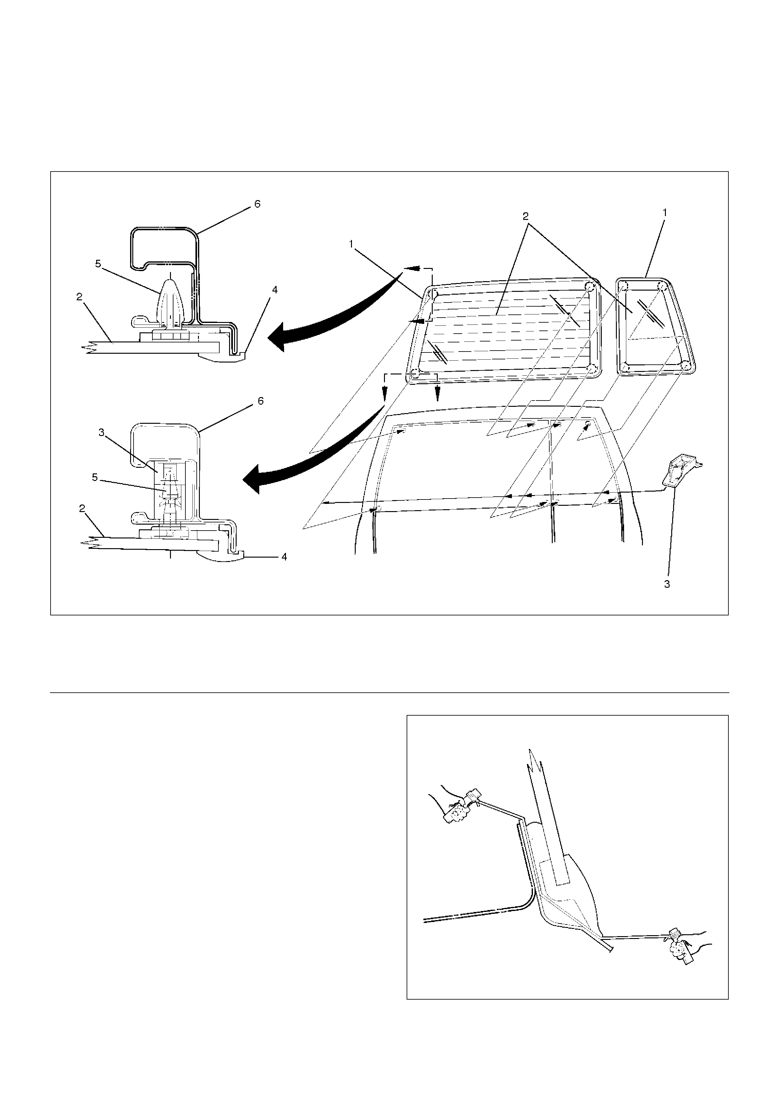
5. Remove rear quarter side glass.
•Refer to Windshield in this section.
Legend
(1) Rear Quarter Upper Trim Panel
(2) Fastener
(3) Rear Quarter Side Glass
(4) Valve Assembly
(5) Ventilation Assembly
(6) Side Outer Panel
(7) Ventilation Assembly
(8) Ventilation Fixing Clip
(9) Rear Quarter Side
(10) Glass Fixing Clip
Installation
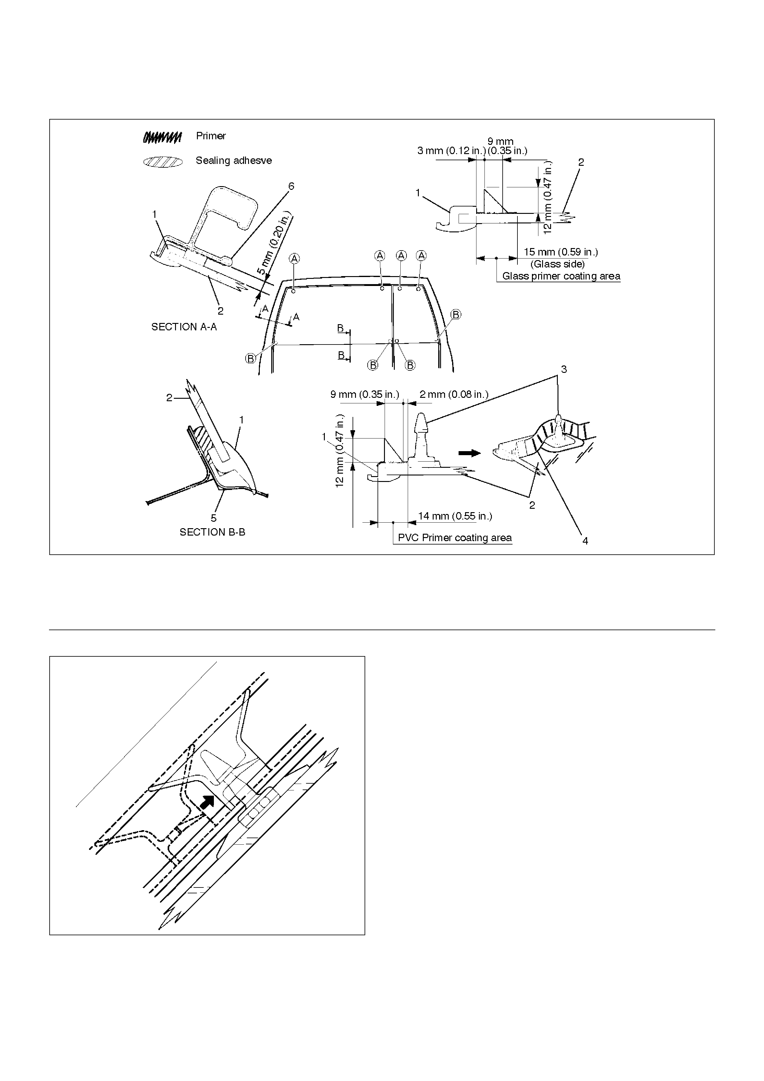
1. Install the rear quarter side glass.
• Clean the bonding surfaces of both the glass and the
body panel.
• Install the fasteners (1) to the fixed positions of the
glass and the body panel.
641RS006
• Always use new fasteners.
• Be absolutely sure to apply glass primer (2) to the
side glass.
• Apply a sealing adhesive (1) to the glass
circumference.
641RS007
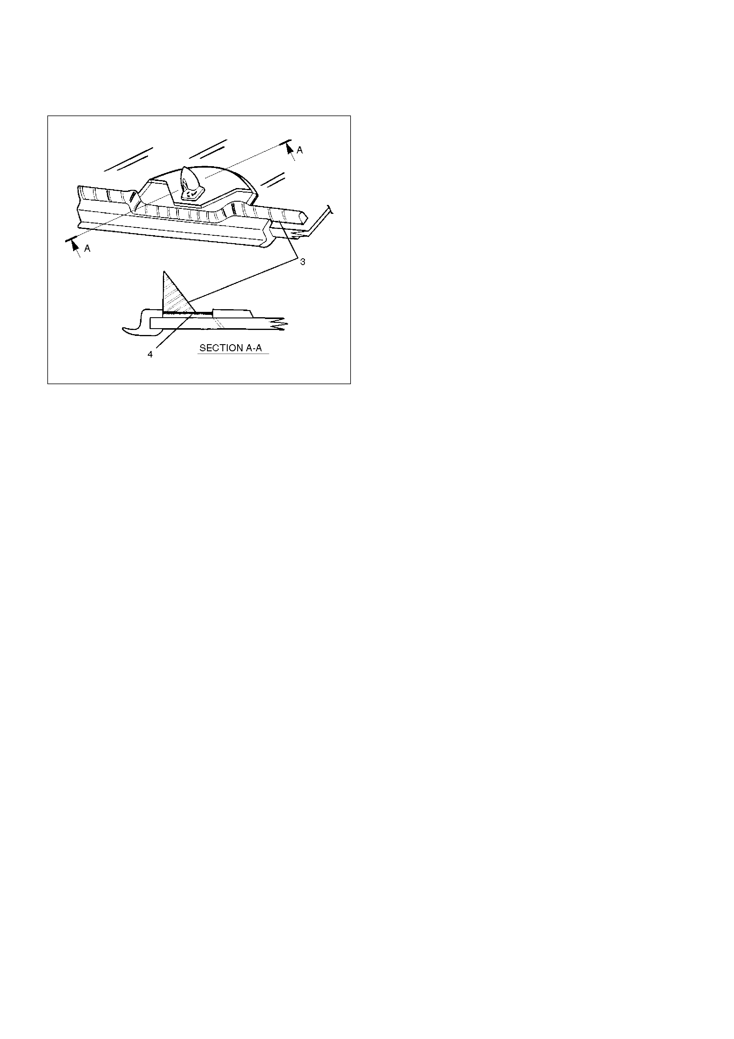
• Apply PVC primer (4) to the A clip portion.
641RS008
• Insert the fixing clip on the side glass into the body
panel.
• Push the side glass against the body panel and bond
them.
• Cure the adhesive at a temperature of 20~30°C
(68~86°F) for 24 hours.
• Check that the rear quarter side glass does not leak
water.
2. Install the valve assembly.
3. Install the ventilation assembly.
4. Install the rear quarter upper trim panel.
Tailgate Glass
Parts Location
682RW008
EndOFCallout
Removal
1. Remove battery ground cable.
2. Remove tailgate trim panel.
3. Remove tailgate sash trim cover (RH only).
•Refer to Tailgate Sash Trim Cover in this section.
4. Remove the tailgate frame cover (LH only).
•Refer to Tailgate Frame Cover (LH) in this
section.
5. Remove tailgate glass.
•Refer to Windshield in this section.
6. Remove tailgate glass clip.
682RS007
Legend
(1) Tailgate Glass Moulding
(2) Tailgate Glass
(3) Tailgate Glass Clip
(4) Glass Moulding
(5) Clip
(6) Body Panel
Installation
682RW009
EndOFCallout
1. Install the tailgate glass clip.
682RS008
2. Install the tailgate glass (2).
• Clean the bonding surfaces of both the tailgate
glass and the tailgate panel.
• Be absolutely sure to apply glass primer to the
tailgate glass and PCV primer to the glass
moulding (1).
• Apply a sealing adhesive to the circumference of
the tailgate glass as shown.
• Insert the clip of the tailgate glass A portion into
the tailgate panel hole to position the glass.
• Install the new tailgate glass clip to the clip of the
tailgate glass B portion while sliding it, and bond
the glass to the tailgate panel by applying
pressure.
Always use new tailgate glass clips.
• Cure the bonding at a temperature of 20~30°C
(68~86°F) for 24 hours.
• Check that the tailgate glass does not leak water.
Legend
(1) Glass Moulding
(2) Tailgate Glass
(3) Clip
(4) Sealing Adhesive
(5) Body Panel
(6) Tailgate Frame
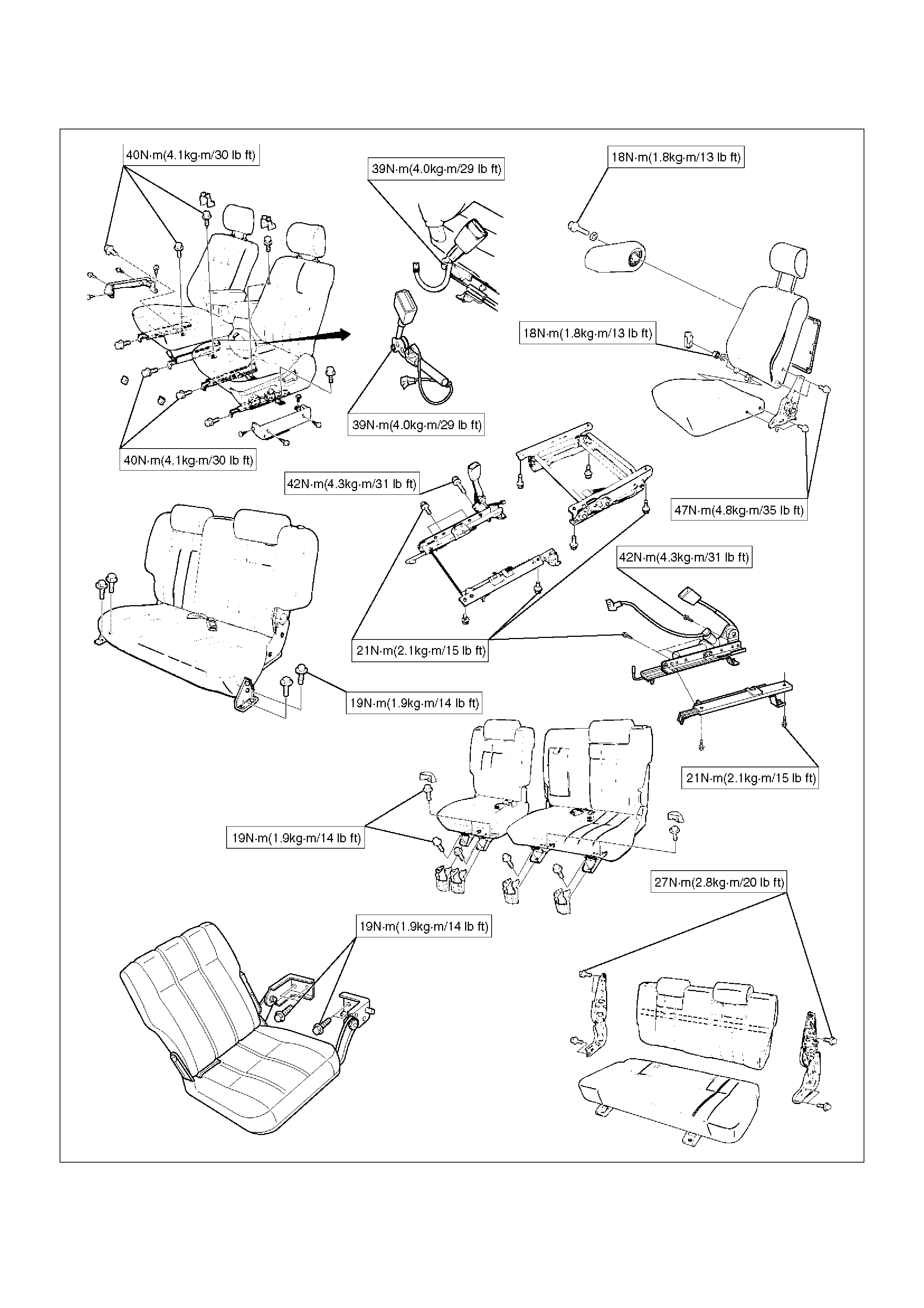
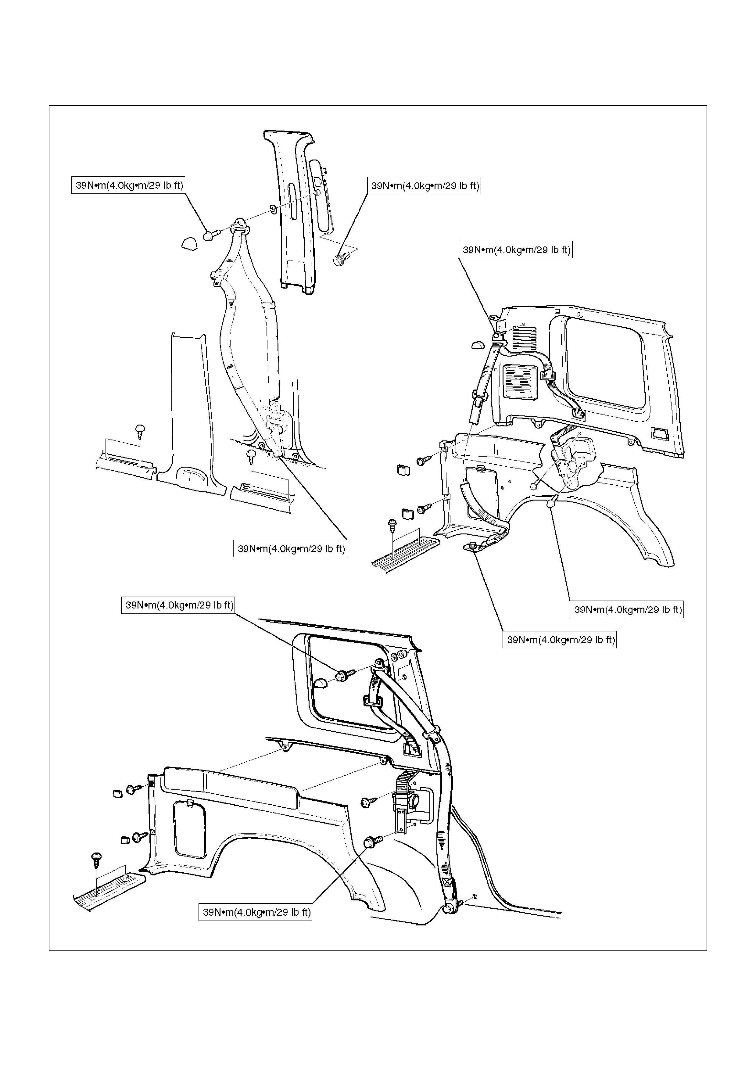
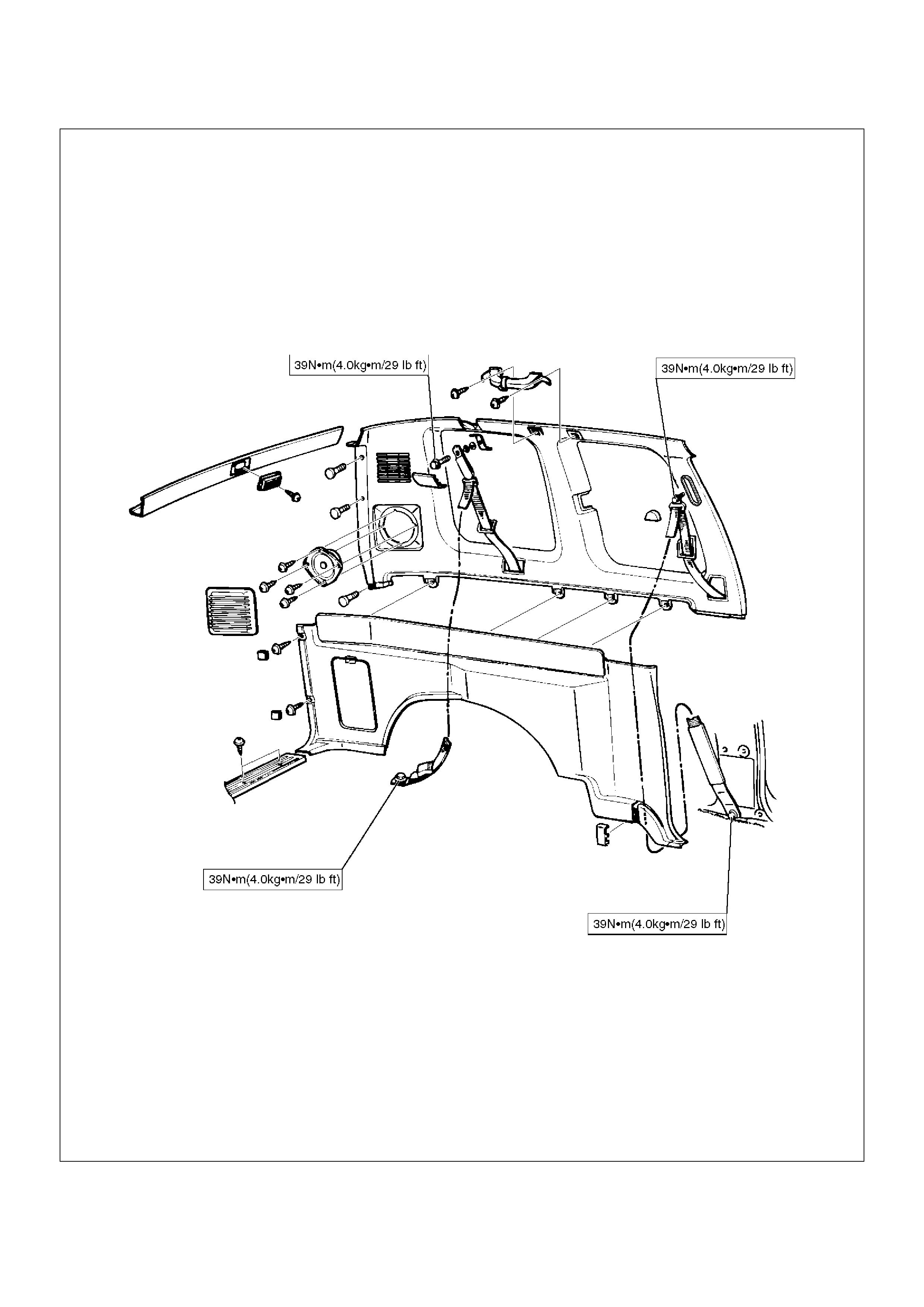
Main Data and Specifications
Torque Specifications
E10RW020
E10RW019
E10RX007
E10RW021
E10RW028
E10RW029
E10RW027
E10RW024
E10RW025
E10RW026
E10RW022
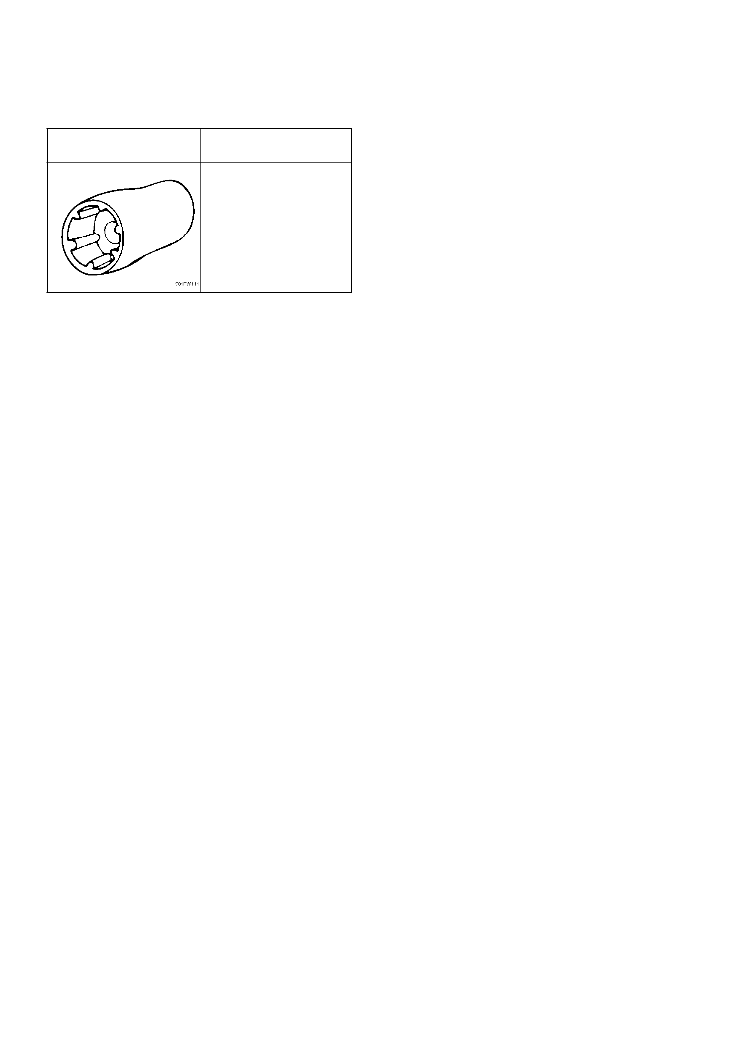
Special Tools
ILLUSTRATION TOOL NO.
TOOL NAME
5–8840–2095–0
(J–34355)
Spare Tire Carrior Bolt
Wrench