
SECTION 1B - SEATS
Service Precaution
Front Seat Assembly
Front Seat Assembly and Associated Parts
Removal
Installation
Disassembled View (LWB)
Disassembly
Reassembly
Power Seat Assembly
General Description
Disassembled View
Disassembly
Reassembly
Power Seat Switch
Removal
Installation
Front Tilt Motor / Rear Tilt Motor / Slide Motor / Recliner
Motor
Parts Location
Removal and Installation
Seat Heater System
General Description
Seat Heater Switch Removal and Installation
Heat Unit Parts Location
Heat Unit Removal and Installation
Rear Seat Assembly
Rear Seat Assembly and Associated Parts
Removal
Installation
Disassembled View (Split Type)
Disassembly (Split Type)
Reassembly (Split Type)
Disassembled View (SWB)
Disassembly
Reassembly
Disassembled View (Bench Type)
Disassembly (Bench Type)
Reassembly (Bench Type)
Third Seat Assembly
Parts Location
Removal
Installation
Disassembled View
Disassembly
Reassembly
Rear Seat Foot Rest
Rear Seat Foot Rest and Associated Parts
Removal
Installation
Main Data and Specifications
Service Precaution
WARNING: IF SO EQUIPPED WITH A
SUPPLEMENTAL RESTRAINT SYSTEM (SRS),
REFER TO THE SRS COMPONENT AND WIRING
LOCATION VIEW IN ORDER TO DETERMINE
WHETHER YOU ARE PERFORMING SERVICE ON
OR NEAR THE SRS COMPONENTS OR THE SRS
WIRING. WHEN YOU ARE PERFORMING SERVICE
ON OR NEAR THE SRS COMPONENTS OR THE
SRS WIRING, REFER TO THE SRS SERVICE
INFORMATION. FAILURE TO FOLLOW WARNINGS
COULD RESULT IN POSSIBLE AIR BAG
DEPLOYMENT, PERSONAL INJURY, OR
OTHERWISE UNNEEDED SRS SYSTEM REPAIRS.
CAUTION: Always use the correct fastener in the
proper location. When you replace a fastener, use
ONLY the exact part number for that application.
HOLDEN will call out those fasteners that require a
replacement after removal.HOLDEN will also call
out the fasteners that require thread lockers or
thread sealant. UNLESS OTHERWISE SPECIFIED,
do not use supplemental coatings (Paints, greases,
or other corrosion inhibitors) on threaded fasteners
or fastener joint interfaces. Generally, such
coatings adversely affect the fastener torque and
the joint clamping force, and may damage the
fastener. When you install fasteners, use the correct
tightening sequence and specifications. Following
these instructions can help you avoid damage to
parts and systems.
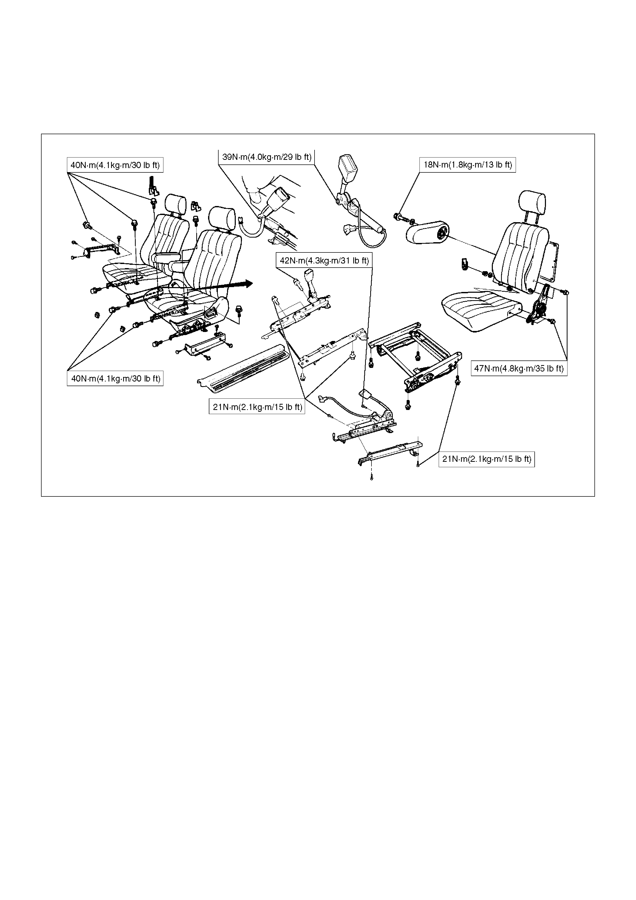
Front Seat Assembly
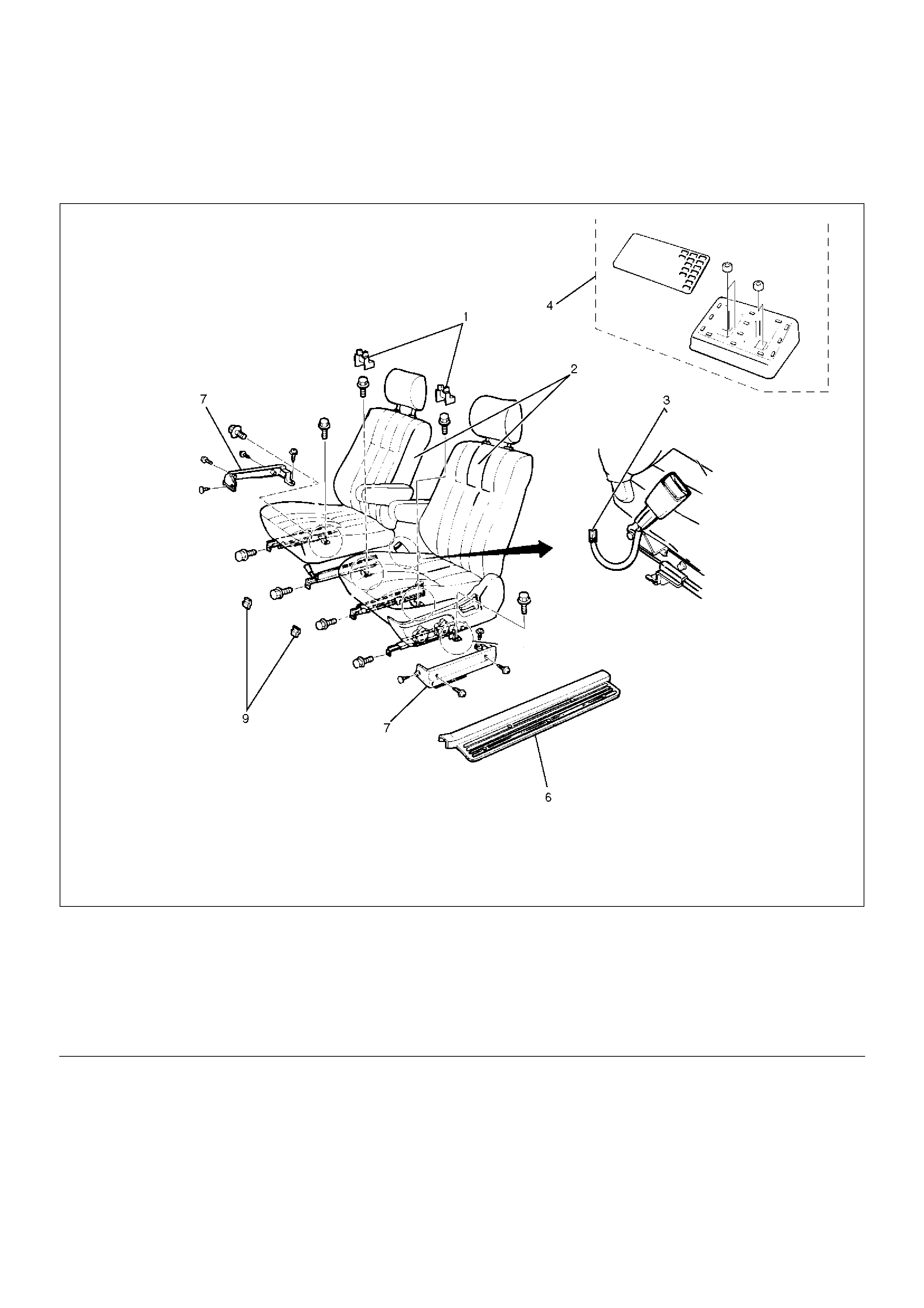
Front Seat Assembly and Associated Parts
750RX016
EndOFCallout
Removal
1. Disconnect the battery ground cable.
2. Remove the front cover.
3. Remove the rear cover.
• Remove the cover fixing screw from the rear
inner cover, if this model is equipped with the
power seats.
4. Remove the door sill plate.
5. Remove the rear seat foot rest.
•Refer to the Rear Seat Foot Rest in this section.
6. Remove the riser cover.
7. Remove the seat belt warning connector (Driver's
side only) or pretensioner harness connector.
8. Remove the front seat assembly.
Legend
(1) Rear Cover
(2) Front Seat Assembly
(3) Seat Belt Warning Connector/Pretensioner
Harness Connector
(4) Rear Seat Foot Rest (LWB)
(5) Seat Rail Cover (SWB)
(6) Door Sill Plate
(7) Riser Cover (LWB)
(8) Seat Slide Cover (SWB)
(9) Front Cover
(10) Seat Rail Cover and Hole Cover (SWB)

• Disconnect the power seat connector, if this
model is equipped with the power seats.
Installation
To install, follow the removal steps in the reverse order,
noting the following points:
1. Tighten the front seat assembly fixing bolts to the
specified torque.
Torque: 40N·m (4.1kg·m/30lbft)
2. Install the longest bolt to the rear inner side fixing
location, if this model is equipped with power seats.
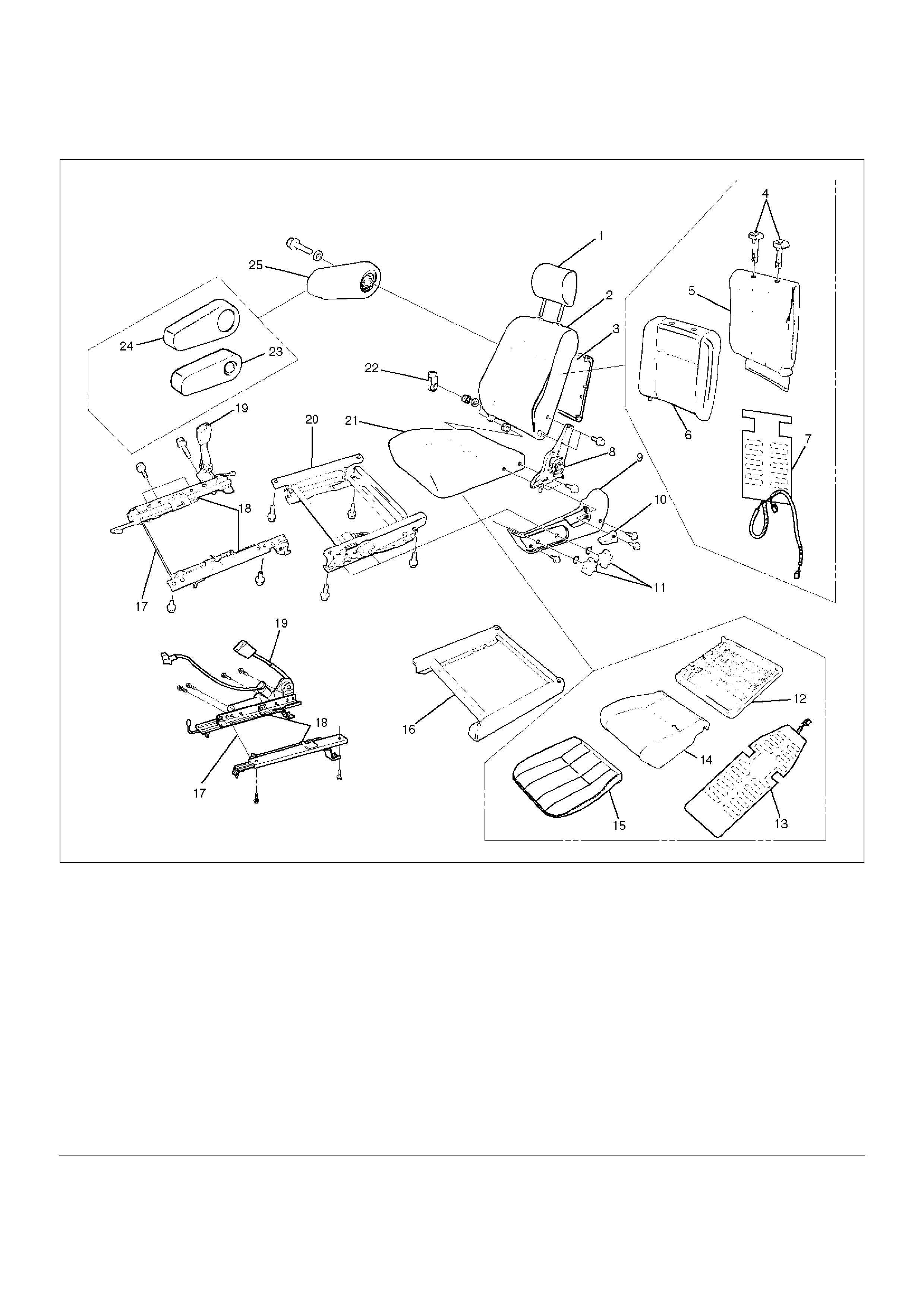
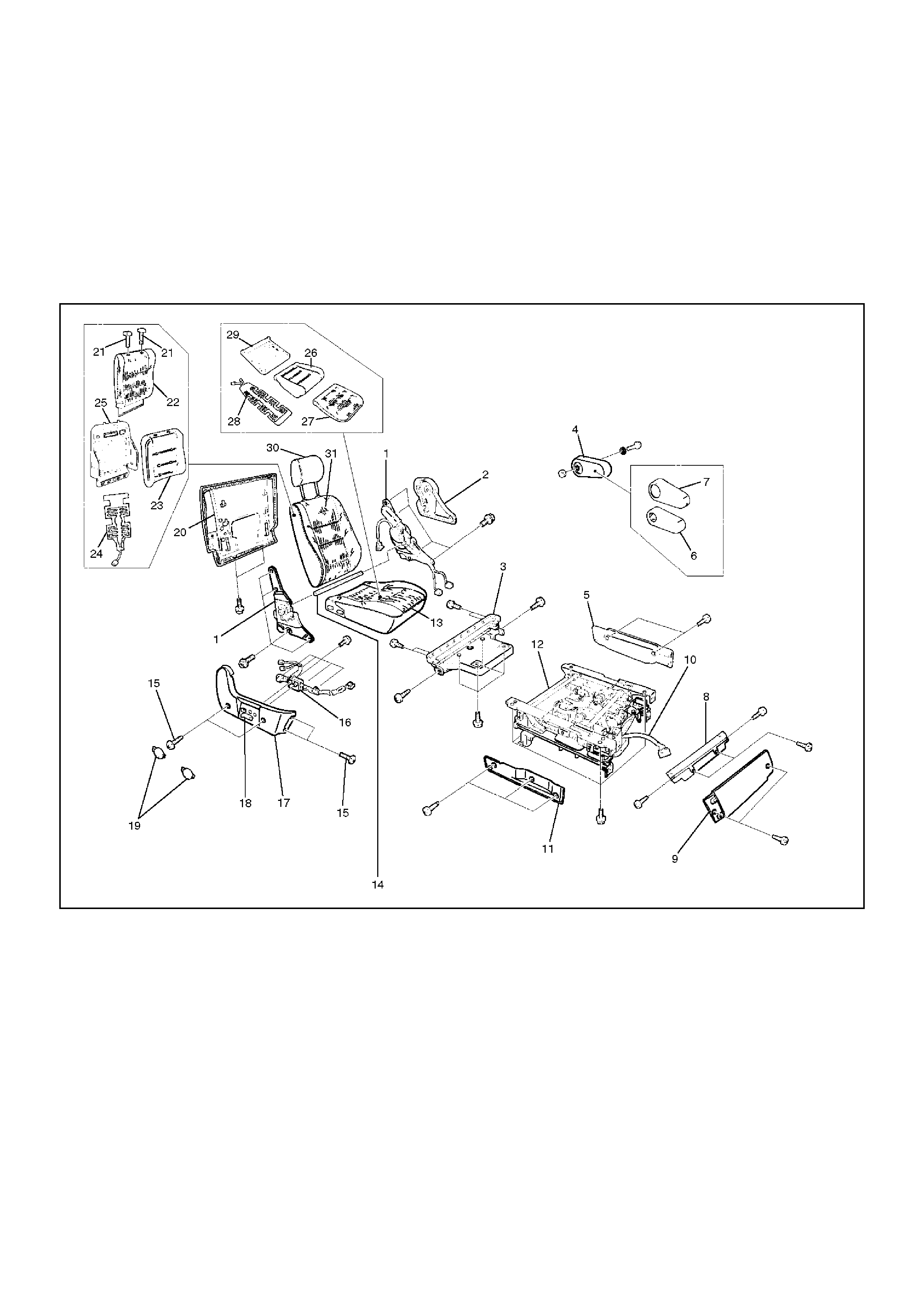
Disassembled View (LWB)
750RX017
EndOFCallout
Legend
(1) Head Rest
(2) Seat Back Assembly
(3) Back Board Assembly
(4) Guide Holder
(5) Trim Cover
(6) Pad & Frame Assembly
(7) Seat Heater Assembly
(8) Reclining Device
(9) Slide Cover
(10) Reclining Knob
(11) Dial (W/Height Adjuster)
(12) Frame Assembly
(13) Seat Heater Assembly
(14) Pad Assembly
(15) Trim Cover
(16) Spacer (W/O Height Adjuster)
(17) Release Wire
(18) Seat Adjuster/Seat Adjuster (W/Pretensioner)
(19) Seat Belt Buckle Assembly
(20) Height Adjuster
(21) Seat Cushion Assembly
(22) Hinge Cover
(23) Pad & Frame Assembly
(24) Trim Cover
(25) Armrest Assembly
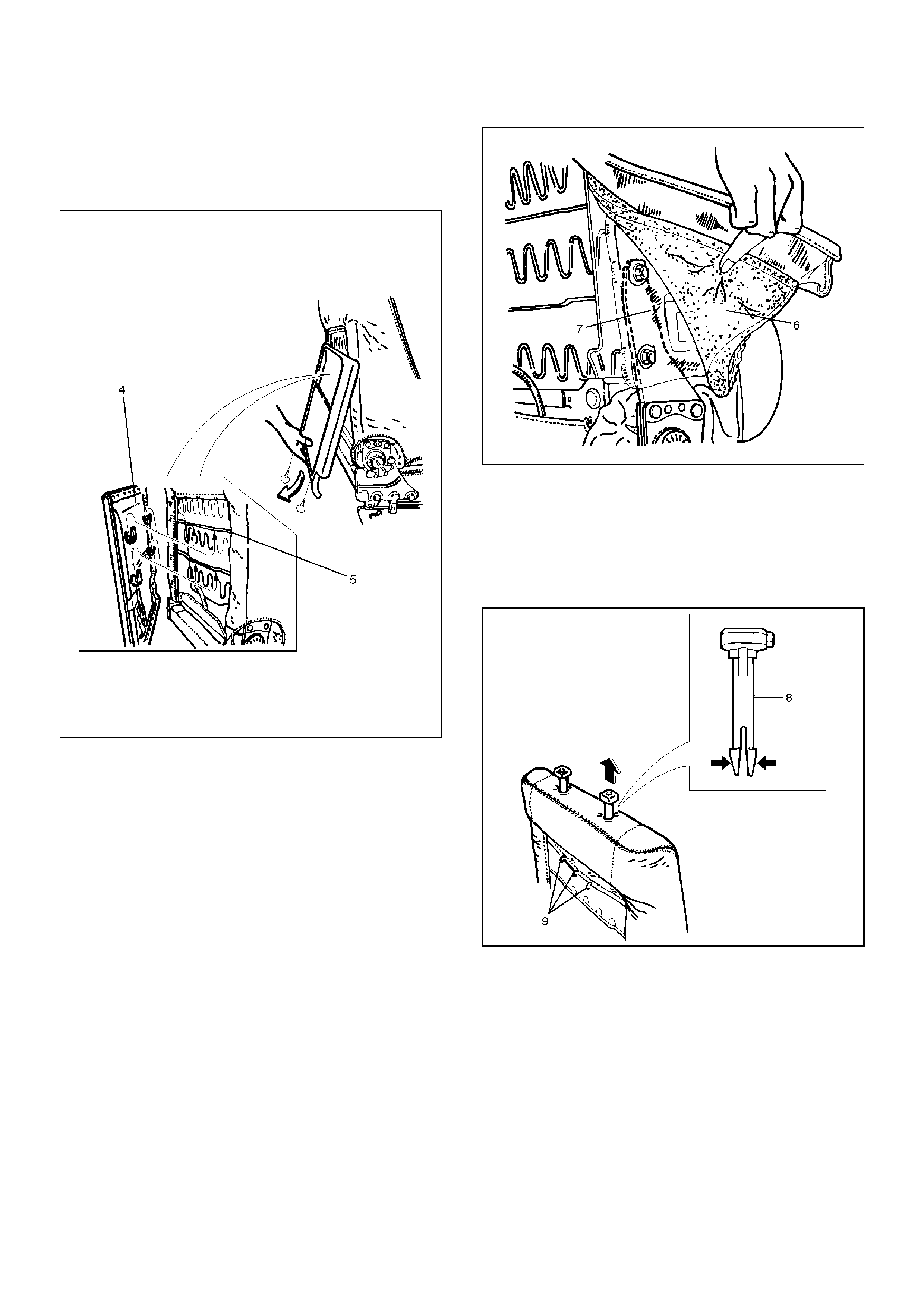
Disassembly
1. Remove the head rest.
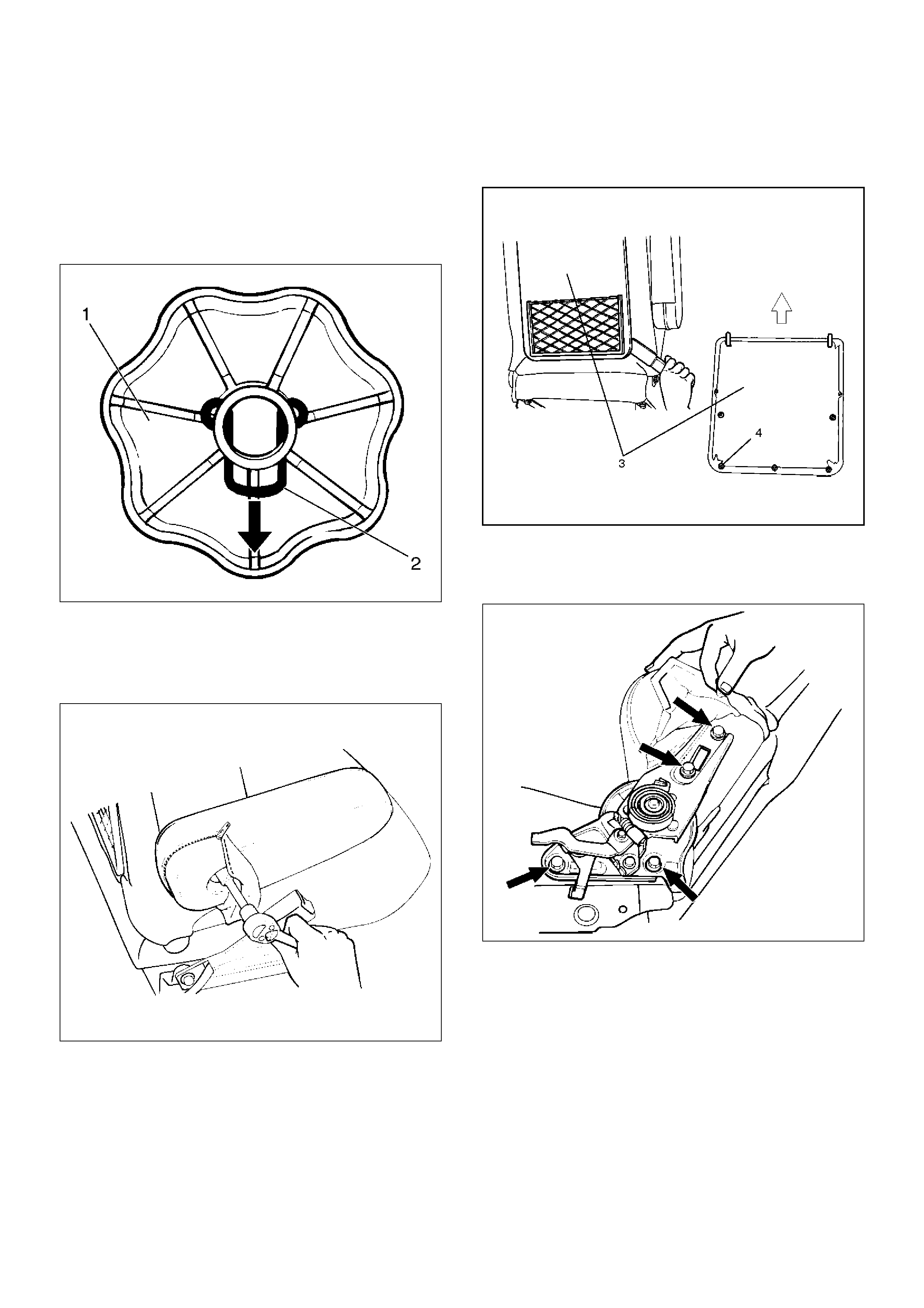
2. Remove the reclining knob.
3. Remove the dial(1) (W/height adjuster).
• Remove the side cover fixing screws and the dial
lock spring(2).
750RW025
4. Remove the side cover.
5. Remove the armrest assembly.
• Open the armrest fastener and remove the
armrest fixing bolt.
750RS004
6. Remove the trim cover.
7. Remove the pad and frame assembly.
8. Remove the hinge cover.
9. Remove the back board assembly(3).
• Pull out the back board while prying the clip (4) of
the back board free from the seat back assembly.
750RW032
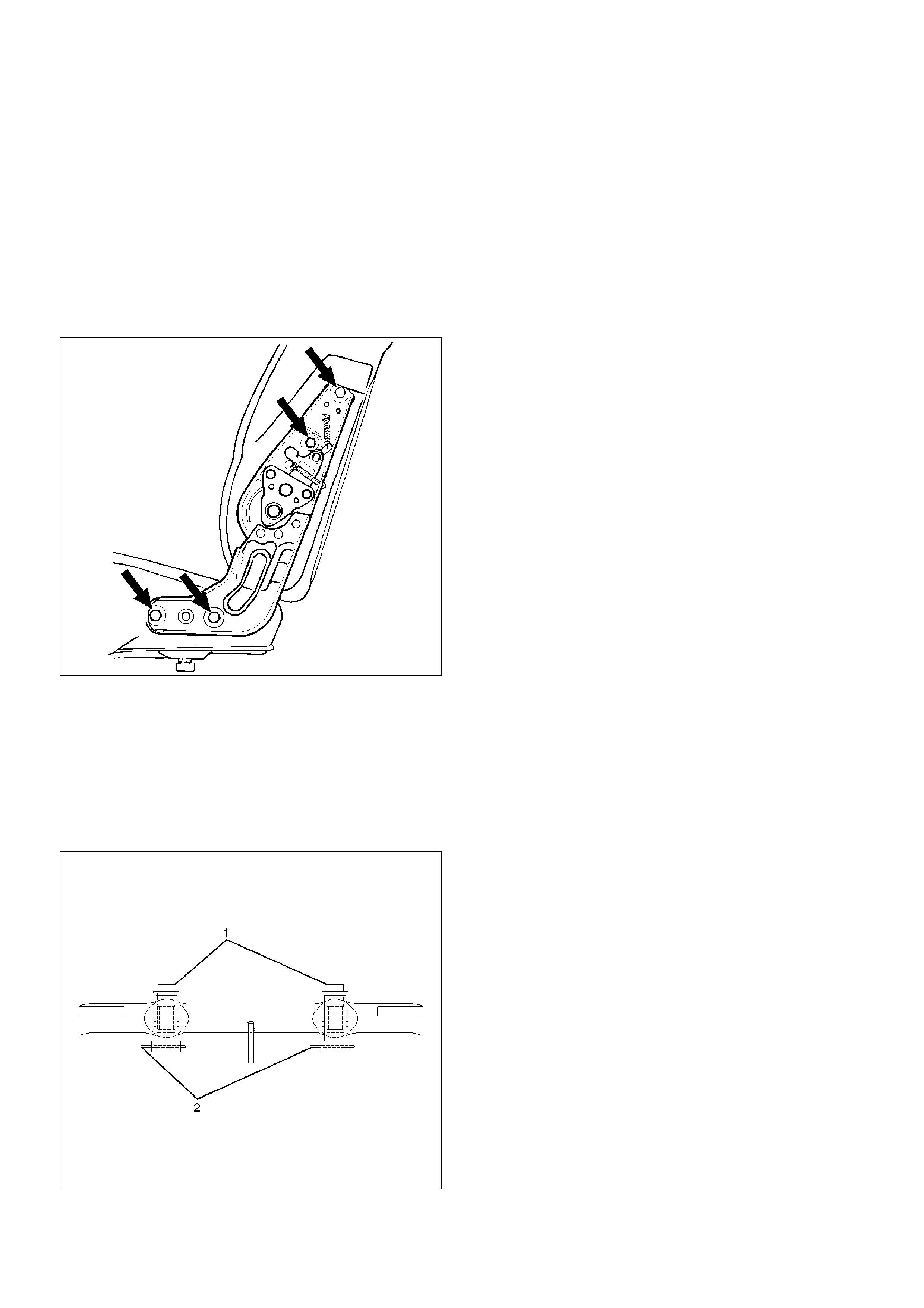
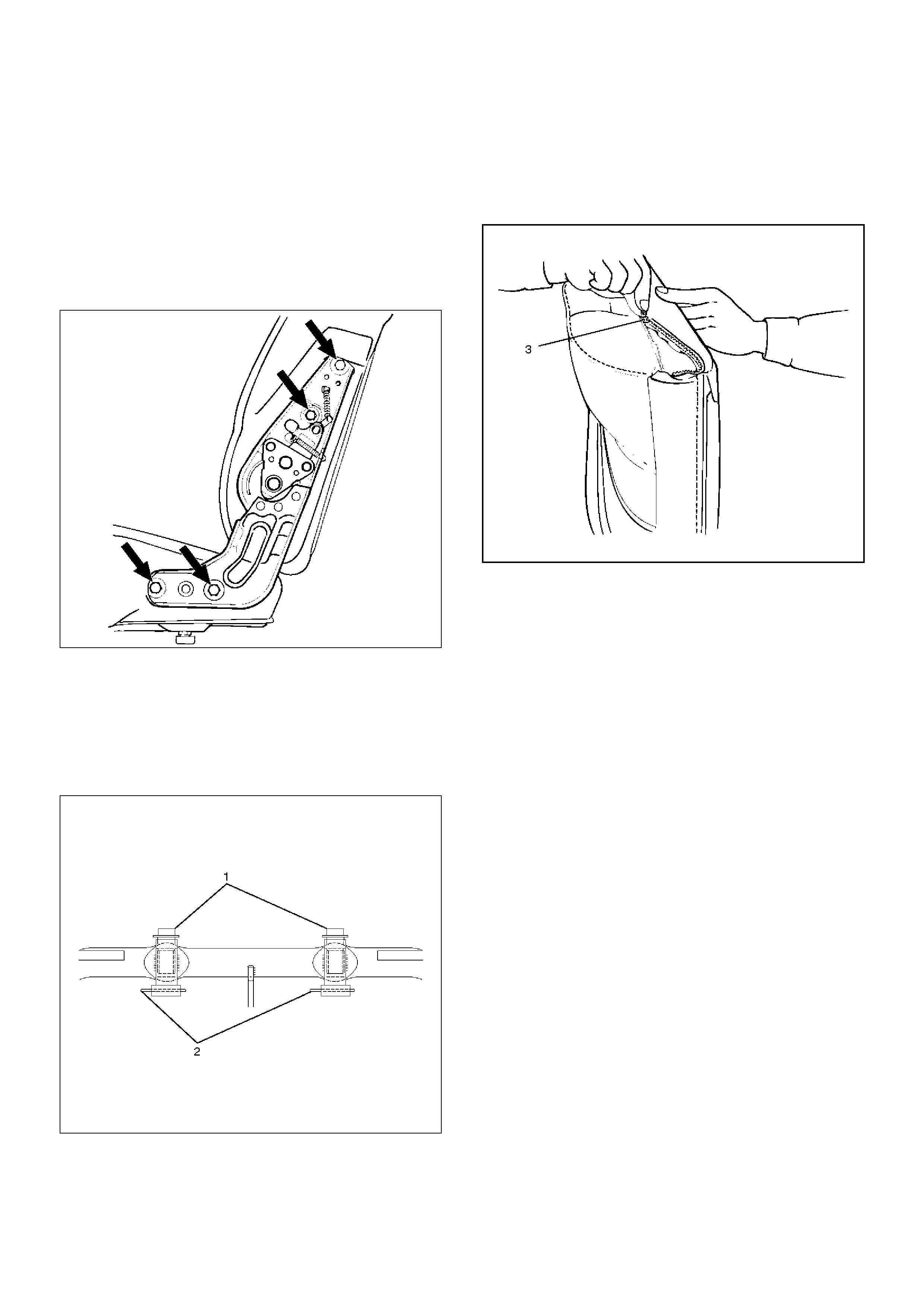
10. Remove the reclining device.
• Turn up the seat back trim cover in order to
remove the reclining device fixing bolts.
750RS006
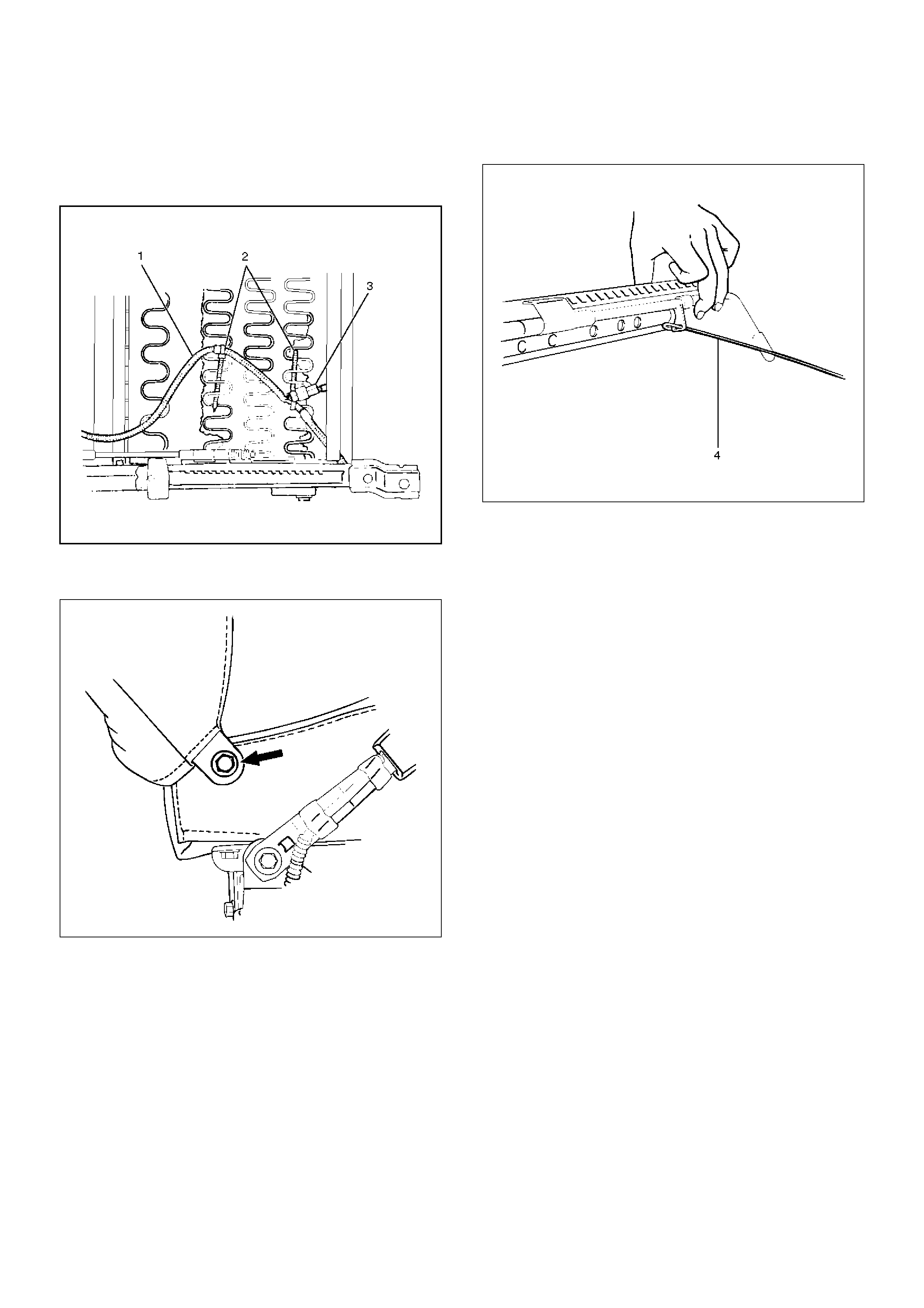
11. Remove the seat back assembly.
• Remove the clips (2) from the seat heater
harness (1), and separate the seat heater
connector (3) (models with the seat heater).
750RW029
• Remove the seat back assembly fixing nut on the
opposite side of the reclining device.
750RS007
12. Remove the guide holder.
• Pull the guide holder out by holding the bottom
end of it from the seat back assembly.
13. Remove the trim cover.
• Remove the trim cover hog rings from the back
side of the seat back.
• With close attention paid to the hog rings and the
wire which connect the trim cover and the pad
and frame assembly, remove the trim cover while
turning it up.
14. Remove the pad and frame assembly.
15. Remove the seat heater assembly.
16. Remove the seat adjuster.
• Disconnect the release wire(4) and remove the
fixing bolts.
750RW006
• Remove the seat belt buckle assembly.
17. Remove the height adjuster.
18. Remove the spacer (W/O height adjuster).
19. Remove the seat cushion assembly.
20. Remove the trim cover.
• Remove the trim cover hog rings from the back
side of the seat cushion assembly.
• With close attention paid to the hog rings and the
wire which connect the trim cover and the pad
and frame assembly, remove the trim cover while
turning it up.
21. Remove the frame assembly.
22. Remove the pad assembly.
23. Remove the seat heater assembly.
Reassembly
To reassembly, follow the disassembly steps in the
reverse order, noting the following point.
1. Tighten the armrest assembly fixing bolts to the
specified torque.
Torque: 18N·m (1.8 kg·m/13lbft)
2. Tighten the reclining device fixing bolts to the
specified torque.
Torque: 47N·m (4.8kg·m/35lbft)
• back board free from the seat back assembly.
3. Remove the reclining device.
• Turn up the seat back trim cover in order to
remove the reclining device fixing bolts.
Power Seat Assembly
General Description
The circuit consists of the power seat switch, front tilt
motor (driver's seat only), rear tilt motor (driver's seat
only), slide motor and the recliner motor.
The power seat switch has a tilt & slide switch and a
recliner switch.
The motor built in the seat can be actuated by operating
these switches to move the seat to desired position,
independent of the position of the starter switch.
Disassembled View
750RS011
Legend
(1) Reclining Device
(2) Inner Cover
(3) Rear Cover
(4) Armrest Assembly
(5) Inner Lower Cover
(6) Pad & Frame Assembly
(7) Trim Cover
(8) Front Lower Cover
(9) Front Cover
(10) Power Seat Harness
(11) Outer Lower Cover
(12) Adjuster Assembly
(13) Seat Cushion Assembly
(14) Connecting Shaft
(15) Outer Cover Fixing Screws
(16) Switch Assembly
(17) Outer Cover
(18) Switch Knob
(19) Outer Cover Cap
(20) Back Board Assembly
(21) Guide Holder
(22) Trim Cover
(23) Pad Assembly
(24) Seat Heater
(25) Frame Assembly
(26) Pad Assembly
(27) Trim Cover
(28) Seat Heater
(29) Frame Assembly
(30) Head Rest
(31) Seat Back Assembly

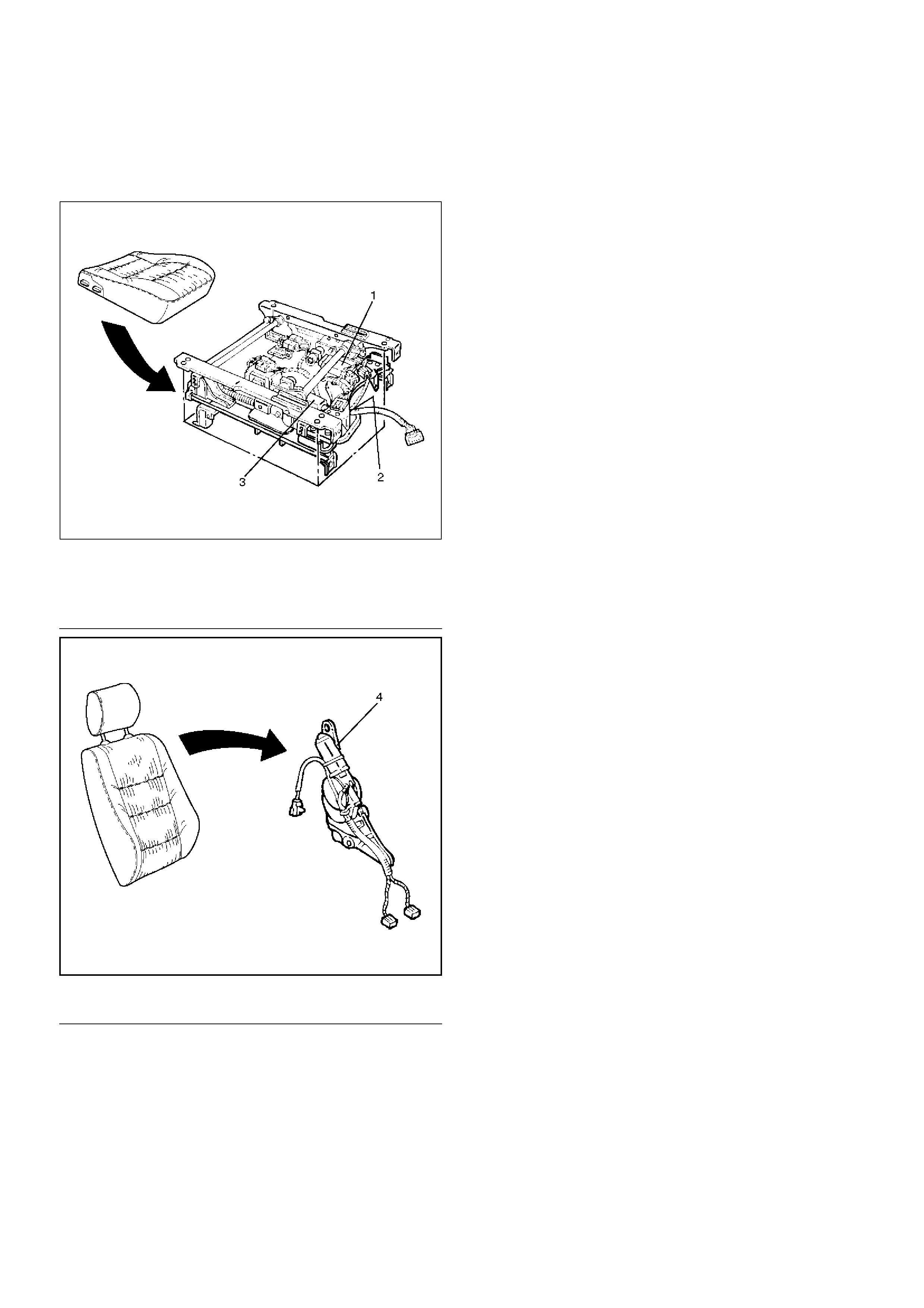
Disassembly
1. Disconnect the battery ground cable.
2. Remove the head rest.
3. Remove the switch knob.
• Pull the switch knob out.
4. Remove the outer cover cap.
5. Remove the outer cover fixing screws.
• Pull up the outer cover(1) to remove the cover
from the reclining device(2).
750RS012
6. Remove the front cover.
7. Remove the front lower cover.
8. Remove the rear cover.
9. Remove the outer cover.
• Disconnect the switch connectors and remove
the harness fixing clips.
10. Remove the switch assembly.
• Remove the switch fixing screws from the outer
cover.
11. Remove the armrest assembly.
• Open the armrest fastener and remove the fixing
bolt.
750RS004
12. Remove the trim cover.
13. Remove the pad & frame assembly.
14. Remove the inner cover
• Remove the cover fixing screw.
• Pull up the inner cover to remove the cover from
the reclining device(3).
750RW007
15. Remove the back board assembly(4).
• Remove the board fixing screws.
• Pull the back board downward and remove the
board from the seat back frame(5).
750RW008
16. Remove the reclining device(7).
• Remove the device lower side fixing bolt in order
to separate the seat back from the seat cushion.
• Disconnect the seat heater connector.
• Remove the trim cover(6) hog rings from the
backside of the seat back assembly.
• Turn up the seat back trim cover to remove the
reclining device upper side fixing bolt.
• Disconnect the connecting shaft and the reclining
device connectors.
750RW009
17. Remove the seat back assembly.
18. Remove the guide holder(8).
• Remove the trim cover fixing hog rings(9) from
the backside of the seat back assembly.
• Hold the tip end of the guide holder and pull the
holder out from the seat back assembly.
750RW010
19. Remove the trim cover.
• Remove the trim cover hog rings from the
backside of the seat back.
• With close attention paid to the hog rings and the
wire which connect the trim cover and pad &
frame assembly, remove the trim cover while
turning it up.
20. Remove the seat heater.
21. Remove the pad assembly.
22. Remove the frame assembly.
23. Remove the outer lower cover.
24. Remove the inner lower cover.
25. Remove the adjuster assembly.
•Disconnect the connectors and remove the fixing
bolts.
•Remove the power seat harness from the
adjuster assembly.
26.Remove the seat cushion assembly.
27.Remove the trim cover.
•Remove the trim cover hog rings from the
backside of the seat cushion assembly.
•With close attention paid to the hog rings and the
wire which connect the trim cover and the pad &
frame assembly, remove the trim cover while
turning it up.
28.Remove the seat heater.
29.Remove the frame assembly.
30.Remove the pad assembly.
Reassembly
To reassemble, follow the disassembly steps in the
reverse order, noting the following point.
1.Tighten the fixing bolts to the specified torque.
•Refer to the Torque Specifications in this section.
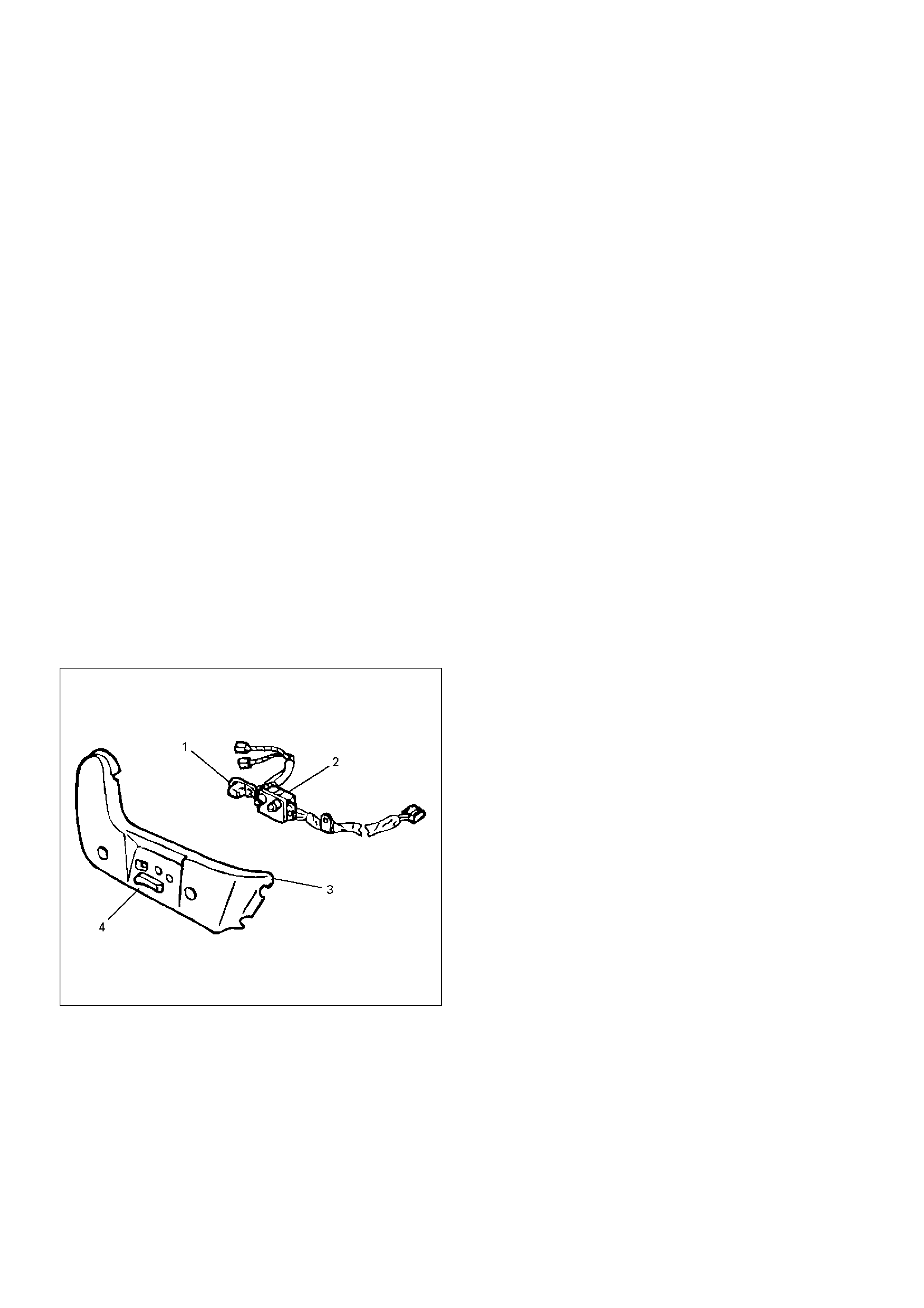
Power Seat Switch
Removal
1.Remove the side cover(3).
•Refer to the Power Seat Assembly disassembly
steps in this section.
2. Remove the tilt & slide switch lever(4).
• Hold the switch lever with your fingers and pull it
toward you.
3. Remove the tilt & slide switch(2).
• Remove two screws.
4. Remove the recliner switch(1).
• Remove two screws.
750RS025
Installation
To install, follow the removal steps in the reverse order.
Seat Heater System
General Description
The circuit consists of the starter switch, seat heater
switch and the heat unit.
The seat heater is provided in driver's and front
passenger seats (as option).
When the seat heater switch is ON, the seat heat built in
the seat back and cushion is switched on to warm the
seats.
To prevent the seats from being overheated, the circuit
is fitted with a thermostat.
Seat Heater Switch Removal and
Installation
Refer to the Seat Heater Switch in Lighting System
section.
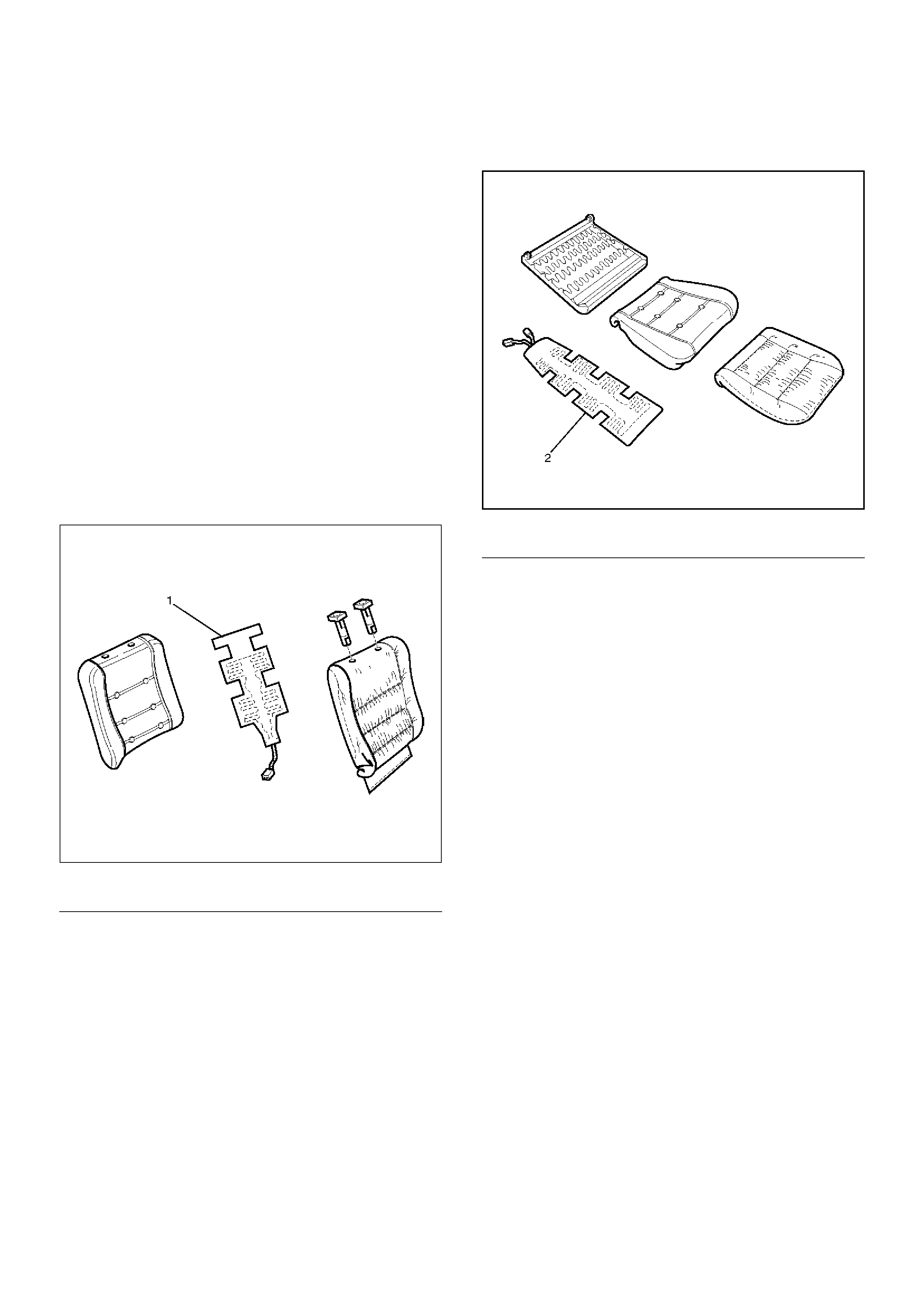
Heat Unit Parts Location
750RS018
EndOFCallout
750RS019
EndOFCallout
Heat Unit Removal and Installation
Refer to the Power Seat Assembly in this section.
Legend
(1) Heat Unit (Seat Back Side)
Legend
(2) Heat Unit (Seat Cushion Side)
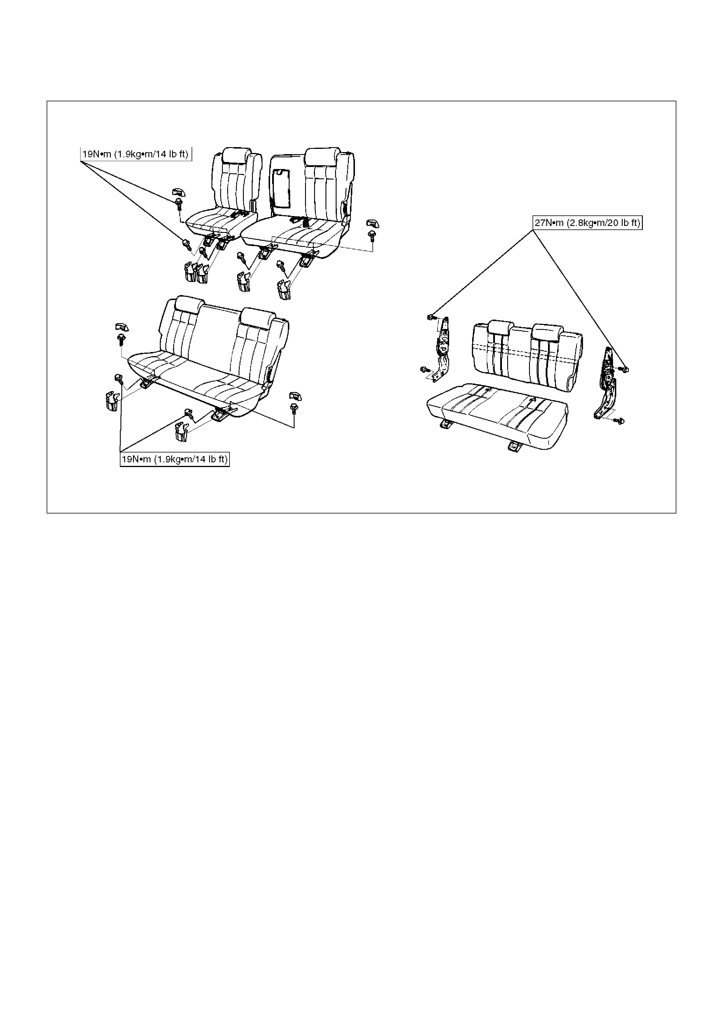
Rear Seat Assembly
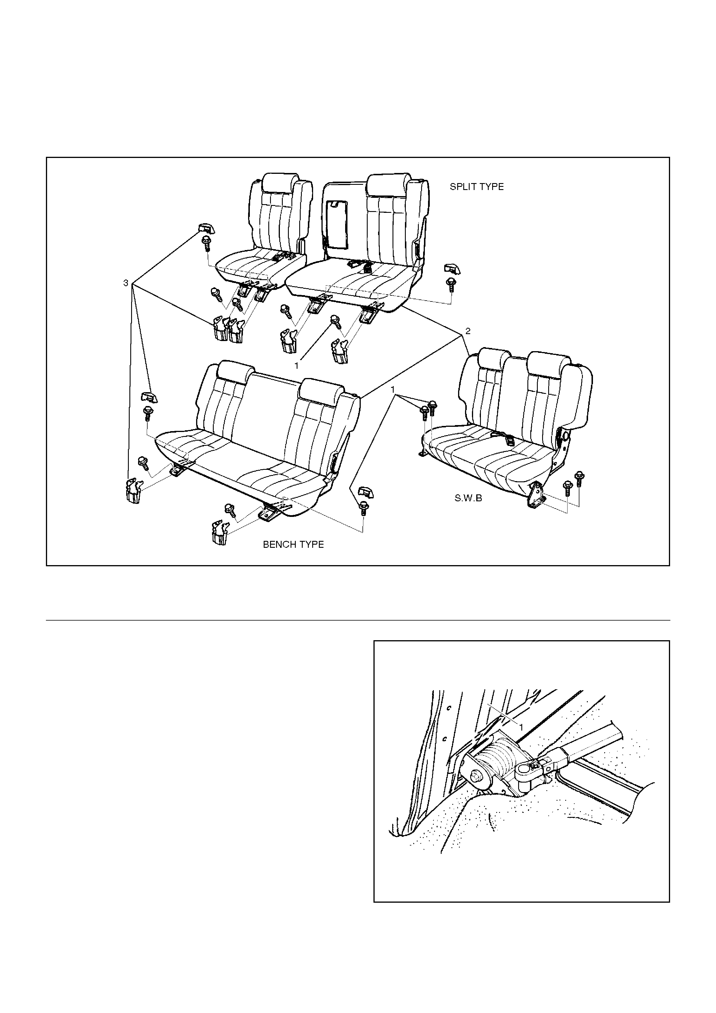
Rear Seat Assembly and Associated Parts
755RW031
EndOFCallout
Removal
1. Unlock the rear seat(1) lock to remove it.
2. Remove the mounting bracket cover.
3. Remove the fixing bolts.
755RS002
4. Remove the rear seat assembly.
Legend
(1) Fixing Bolts
(2) Rear Seat Assembly
(3) Mounting Bracket Cover
Installation
To install, follow the removal steps in the reverse order,
noting the following point.
1. Tighten the rear seat fixing bolts to the specified
torque.
Torque: 19N·m (1.9kg·m/14lbft)
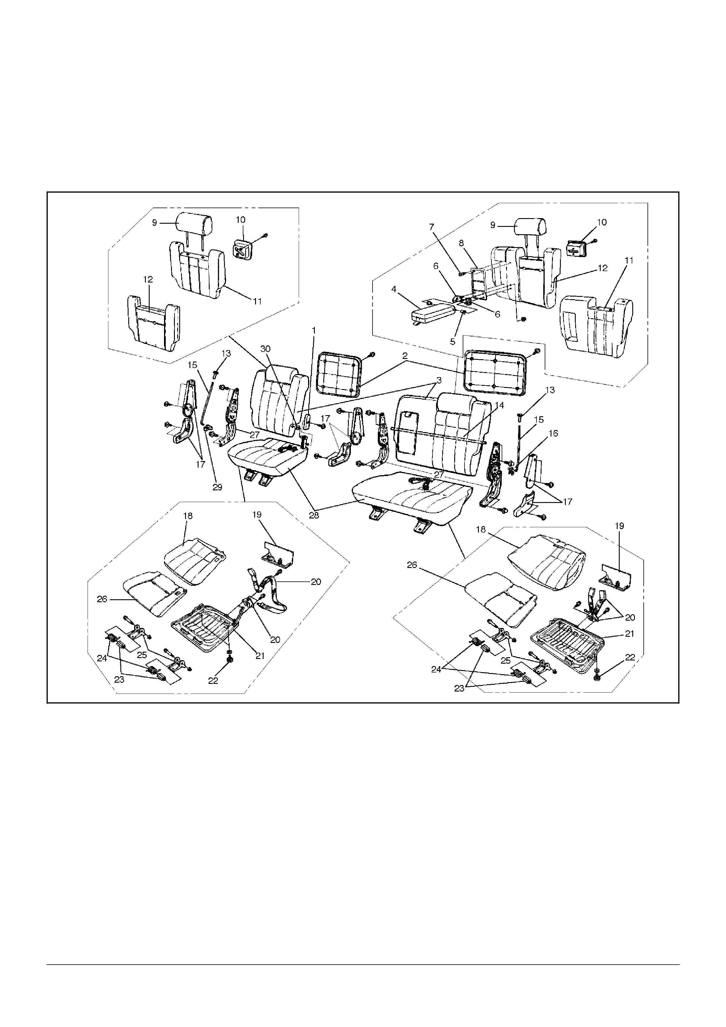
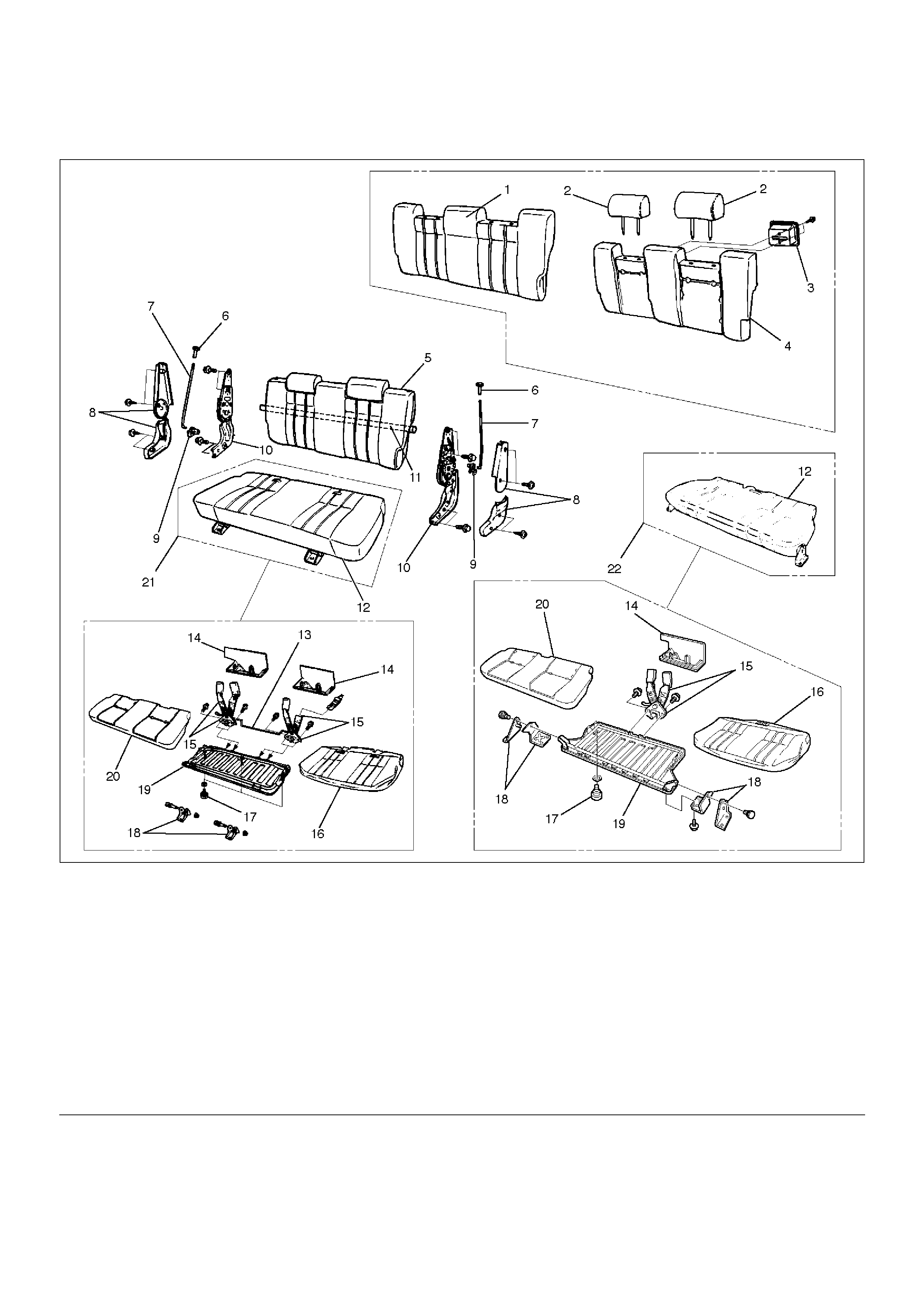
Disassembled View (Split Type)
755RW056
EndOFCallout
Legend
(1) Free Hinge Cover
(2) Back Board
(3) Seat Back Assembly
(4) Armrest Assembly
(5) Bush
(6) Armrest Set Bracket
(7) Clip
(8) Armrest Board
(9) Pillow Assembly
(10) Band Hook Cover
(11) Trim Cover
(12) Pad & Frame Assembly
(13) Release Knob
(14) Connecting Shaft
(15) Release Rod
(16) Linkage Bush
(17) Device Cover
(18) Trim Cover
(19) Seat Lock Cover
(20) Rear Seat Belt Buckle and Lock Assembly
(21) Frame Assembly
(22) Stopper Rubber
(23) Spring Collar
(24) Return Spring
(25) Mounting Bracket
(26) Pad Assembly
(27) Reclining Device
(28) Seat Cushion Assembly
(29) Linkage Bush
(30) Bush

Disassembly (Split Type)
1. Remove the back board.
• Remove the clips and the back board.
2. Remove the device cover.
3. Remove the release knob.
• Turn the knob counterclockwise to remove it.
4. Remove the release rod.
• Disconnect the rod from the linkage bush.
5. Remove the reclining device.
755RS004
6. Remove the connecting shaft.
7. Remove the seat back assembly.
8. Remove the pillow assembly.
• Turn up the seat back trim cover and slit the pad
from the back around to the place where the lock
spring(2) of the guide bush(1) is.
Then insert a finger through the slit and pull out the
pillow while you are pressing down on the lock
spring.
755RS017
9. Remove the band hook cover.
10. Remove the armrest assembly.
• Turn up the seat back trim cover and remove the
fixing nuts.
11. Remove the armrest set bracket.
12. Remove the armrest board.
13. Remove the trim cover.
• Remove the trim cover fixing hog rings from the
backside of the seat back.
• With close attention paid to the hog rings and the
wire which connect the trim cover and the pad
and frame assembly, remove the trim cover while
turning it up.
14. Remove the pad & frame assembly.
15. Remove the seat cushion assembly.
16. Remove the seat lock cover.
17. Remove the rear seat belt buckle and lock
assembly.
18. Remove the mounting bracket.
19. Remove the return spring.
20. Remove the spring collar.
21. Remove the trim cover.
• Remove the hog rings and pull the trim cover out
from the frame assembly groove.
• With close attention paid to the hog rings and the
wire which connect the trim cover and the pad &
frame assembly, remove the trim cover while
turning it up.
22. Remove the frame assembly.
23. Remove the pad assembly.
24. Remove the stopper rubber.

Reassembly (Split Type)
To reassemble, follow the disassembly steps in the
reverse order, noting the following point.
1. Tighten the reclining device fixing bolts to the
specified torque.
Torque: 27N·m (2.8kg·m/20lbft)
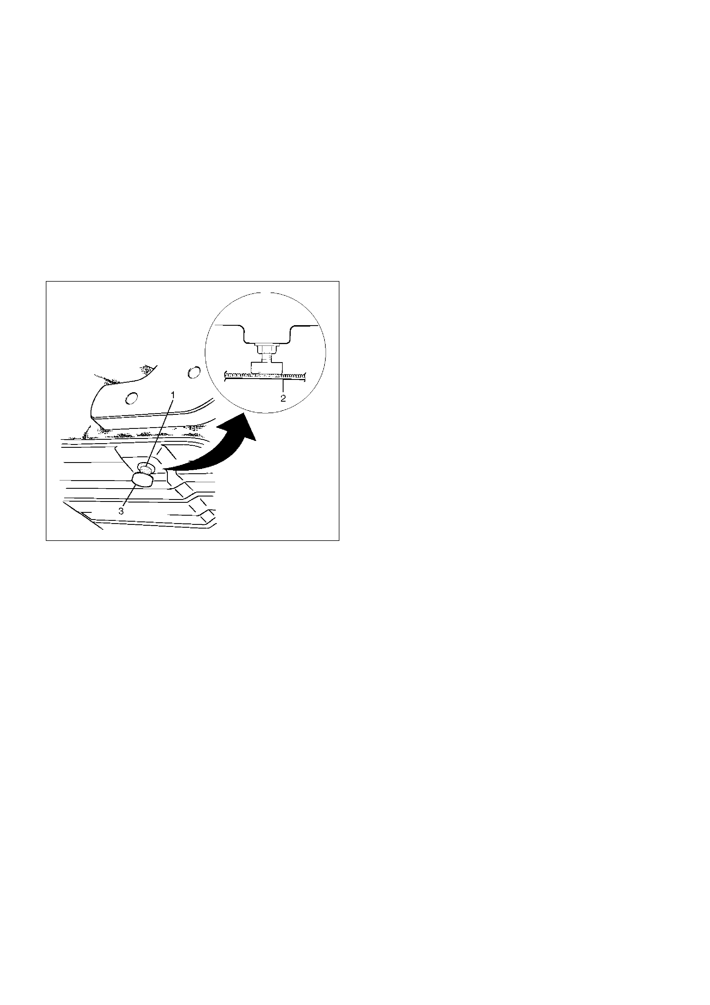
2. Loosen the rubber stopper lock nut(1). Adjust the
stopper(3) so there is no clearance between the
bottom of the stopper and the carpet(2) while you
make sure the rear seat is firmly locked.
Then tighten the lock nut securely.
755RS005
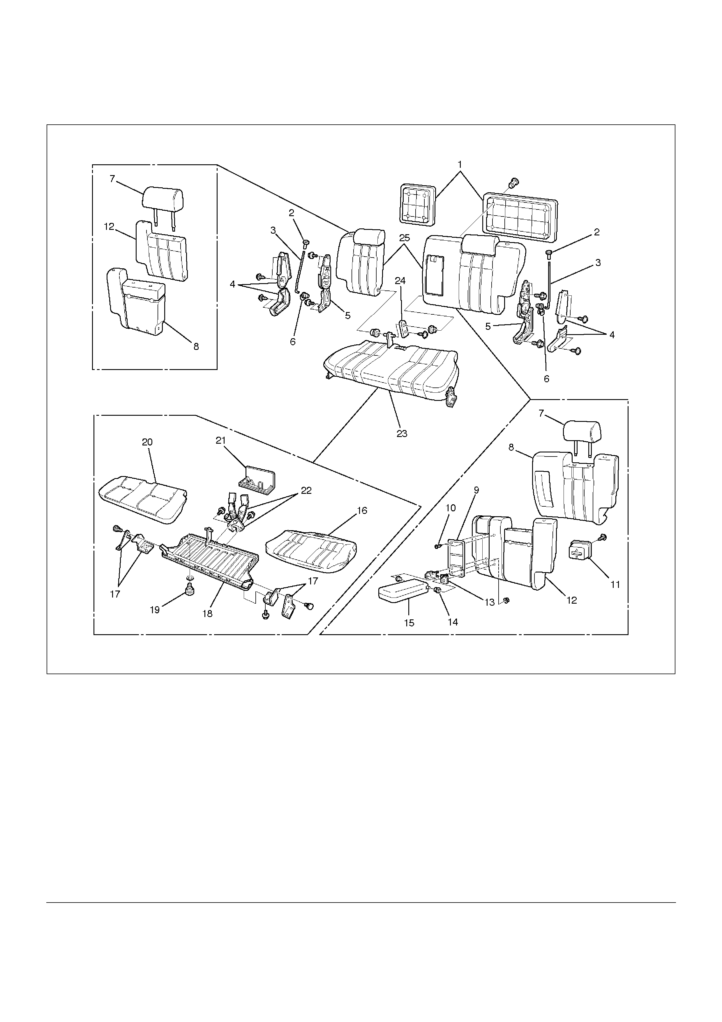
Disassembled View (SWB)
755RW036
EndOFCallout
Legend
(1) Back Board
(2) Release Knob
(3) Release Rod
(4) Device Cover
(5) Reclining Device
(6) Linkage Bush
(7) Pillow Assembly
(8) Pad & Frame Assembly
(9) Armrest Board
(10) Clip
(11) Band Hook Cover
(12) Trim Cover
(13) Armrest Set Bracket
(14) Bush
(15) Armrest Assembly
(16) Trim Cover
(17) Mounting Bracket
(18) Frame Assembly
(19) Stopper Rubber
(20) Pad Assembly
(21) Seat Lock Cover
(22) Rear seat Belt Bukle and Lock Assembly
(23) Seat Cushion Assembly
(24) Free Hinge Cover
(25) Seat Back Assembly
Disassembly
1. Remove the back board.
• Remove the clips and the back board.
2. Remove the device cover.
3. Remove the release knob.
• Turn the knob counterclockwise to remove it.
4. Remove the release rod.
• Disconnect the rod from the linkage bush.
5. Remove the reclining device.
755RS004
6. Remove the seat back assembly.
7. Remove the pillow assembly.
• Turn up the seat back trim cover and slit the pad
from the back around to the place where the lock
spring(2) of the guide bush(1) is.
Then insert a finger through the slit and pull out the
pillow while you are pressing down on the lock
spring.
755RS017
8. Remove the band hook cover.
9. Remove the armrest assembly.
• Turn up the seat back trim cover and remove the
fixing nuts.
10. Remove the armrest set bracket.
11. Remove the armrest board.
12. Remove the trim cover.
• Remove the trim cover fixing hog rings from the
backside of the seat back.
• With close attention paid to the hog rings and the
wire which connect the trim cover and the pad
and frame assembly, remove the trim cover while
turning it up.
13. Remove the pad & frame assembly.
14. Remove the free hinge cover.
15. Remove the seat cushion assembly.
16. Remove the seat lock cover.
17. Remove the rear seat belt buckle and lock
assembly.
18. Remove the mounting bracket.
19. Remove the trim cover.
• Remove the hog rings and pull the trim cover out
from the frame assembly groove.
• With close attention paid to the hog rings and the
wire which connect the trim cover and the pad &
frame assembly, remove the trim cover while
turning it up.
20. Remove the frame assembly.
21. Remove the pad assembly.
22. Remove the stopper rubber.
Reassembly
To reassemble, follow the disassembly steps in the
reverse order, noting the following point.
1. Tighten the reclining device fixing bolts to the
specified torque.
Torque: 27N·m (2.8kg·m/20lbft)
2. Loosen the rubber stopper lock nut(1). Adjust the
stopper(3) so there is no clearance between the
bottom of the stopper and the carpet(2) while you
make sure the rear seat is firmly locked.
Then tighten the lock nut securely.
755RS005
Disassembled View (Bench Type)
755RW033
EndOFCallout
Legend
(1) Trim Cover
(2) Pillow Assembly
(3) Band Hook Cover
(4) Pad & Frame Assembly
(5) Seat Back Assembly
(6) Release Knob
(7) Release Rod
(8) Device Cover
(9) Linkage Bush
(10) Reclining Device
(11) Connecting Shaft
(12) Seat Cushion Assembly
(13) Connecting Link
(14) Seat Lock Cover
(15) Rear Seat Belt Buckle and Lock Assembly
(16) Trim Cover
(17) Stopper Rubber
(18) Mounting Bracket
(19) Frame Assembly
(20) Pad Assembly
(21) L·W·B
(22) S·W·B
Disassembly (Bench Type)
1.Remove the device cover.
2.Remove the release knob.
•Turn the knob to the counterclockwise to remove
it.
3.Remove the release rod.
•Disconnect the rod from the linkage bush.
4.Remove the reclining device.
755RS004
5.Remove the connecting shaft.
6.Remove the seat back assembly.
7.Remove the band hook cover.
8.Remove the pillow assembly.
•Refer to the Disassembly (Split Type) in this
section.
755RS017
9. Remove the trim cover.
• Open the fastener(3), and with close attention
paid to the hog rings and wire which connect the
trim cover and the pad and frame assembly,
remove the trim cover as you turn it up.
750RW011
10. Remove the pad & frame assembly.
11. Remove the seat cushion assembly.
12. Remove the seat lock cover.
13. Remove the rear seat belt buckle and lock
assembly.
14. Remove the mounting bracket.
15. Remove the trim cover.
• Remove the hog rings and pull the trim cover out
from the frame assembly groove.
• With close attention paid to the hog rings and the
wire which connect the trim cover and the pad
and frame assembly, remove the trim cover while
turning it up.
16. Remove the frame assembly.
17. Remove the pad assembly.
18. Remove the stopper rubber.

Reassembly (Bench Type)
To reassemble, follow the disassembly steps in the
reverse order, noting the following point.
1. Tighten the reclining device fixing bolts to the
specified torque.
Torque: 27N·m (2.8kg·m/20lbft)
2. Loosen the rubber stopper lock nut(1) and adjust
the stopper rubber(3) so there is no clearance
between the bottom of the stopper and the
carpet(2), while ensuring the rear seat is firmly
locked.
Tighten the lock nut securely.
755RS005
Third Seat Assembly
Parts Location
755RW034
EndOFCallout
Removal
1. Disconnect the battery ground cable.
2. Remove the cover.
3. Remove the third seat assembly.
Legend
(1) Cover
(2) Rear Side of LH
(3) Third Seat Assembly
Installation
To reassemble, follow the disassembly steps in the
reverse order, noting the following point.
1. Tighten the reclining device fixing bolts to the
specified torque.
Torque: 19N·m (1.9kg·m/14lbft)
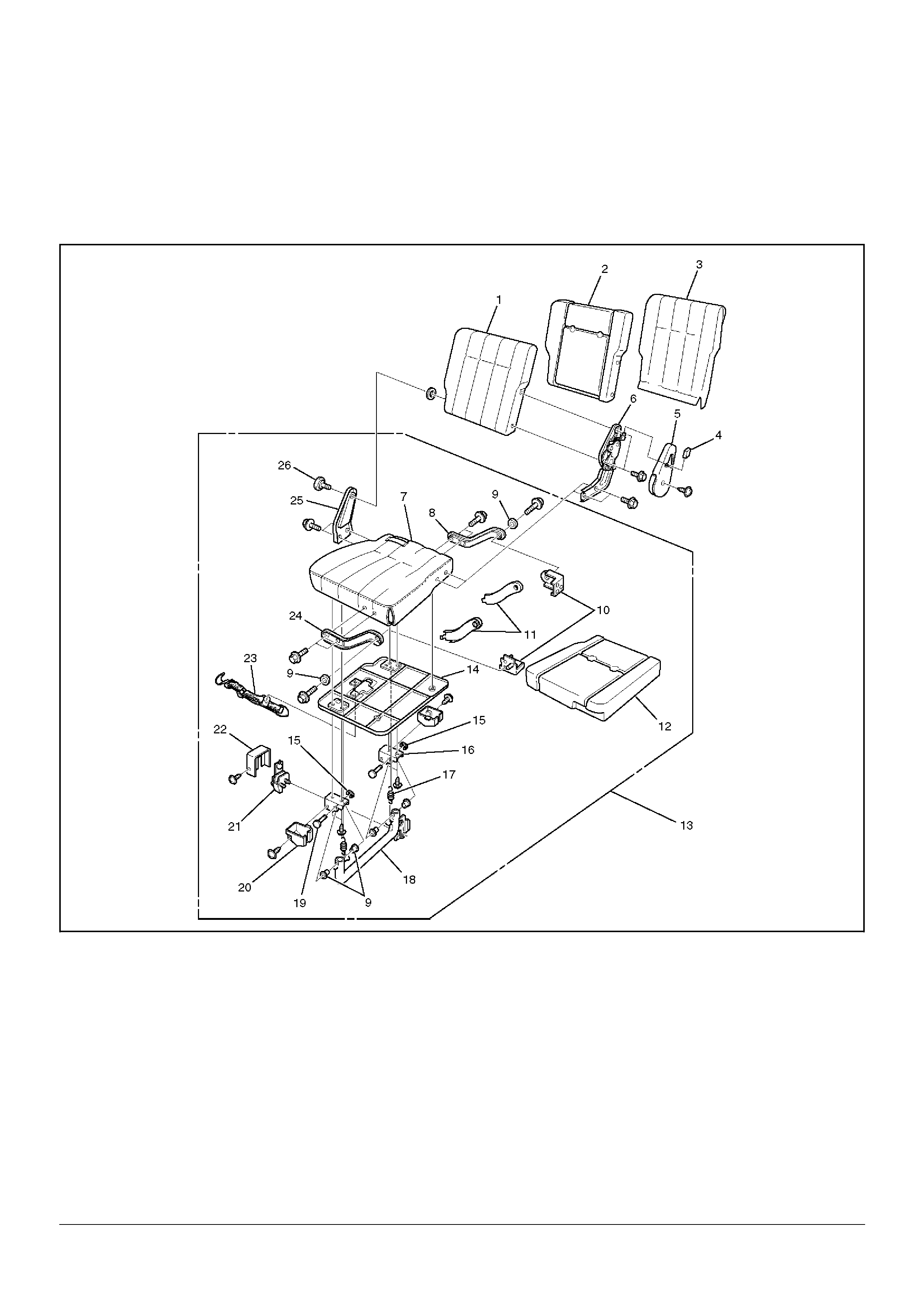
Disassembled View
755RW035
EndOFCallout
Legend
(1) Seat Back Assembly
(2) Pad & Frame Assembly
(3) Trim Cover
(4) Hinge Knob
(5) Hinge Cover
(6) Hinge Assembly
(7) Trim Cover
(8) Arm Bracket
(9) Bush
(10) Bracket
(11) Arm Bracket Cover
(12) Pad & Frame Assembly
(13) Seat Cushion Assembly
(14) Board Assembly
(15) E–Ring
(16) Cam Bracket
(17) Tension Spring
(18) Leg Pipe Assembly
(19) Hing Pin
(20) Lock Cover
(21) Floor Lock Assembly
(22) Lock Cover
(23) Band Assembly
(24) Arm Bracket
(25) Free Hinge
(26) Free Hinge Bolts

Disassembly
1. Remove the hinge knob.
• Pull the knob out from hinge assembly.
2. Remove the hinge cover.
3. Remove the hinge assembly.
4. Remove the free hinge bolt.
5. Remove the seat back assembly.
6. Remove the trim cover.
• Turn up the trim cover from under the seat back
while taking notice of the hog ring and wire.
755RW032
7. Remove the pad & frame assembly.
8. Remove the seat cushion assembly.
9. Remove the free hinge.
10. Remove the lock cover.
11. Remove the floor lock assembly.
12. Remove the leg cover.
13. Remove the leg pipe assembly.
• Remove the E-ring and pull the hinge pin from
cam bracket.
14. Remove the cam bracket.
15. Remove the tension spring.
16. Remove the band assembly.
17. Remove the board assembly.
18. Remove trim cover.
• Remove the hog ring from back side seat
cushion.
• Turn up the trim cover from under the seat back
while taking notice of the hog ring.
19. Remove the arm bracket.
20. Remove the arm bracket cover.
21. Remove the pad & frame assembly.
Reassembly
To reassemble, follow the disassembly steps in the
reverse order.
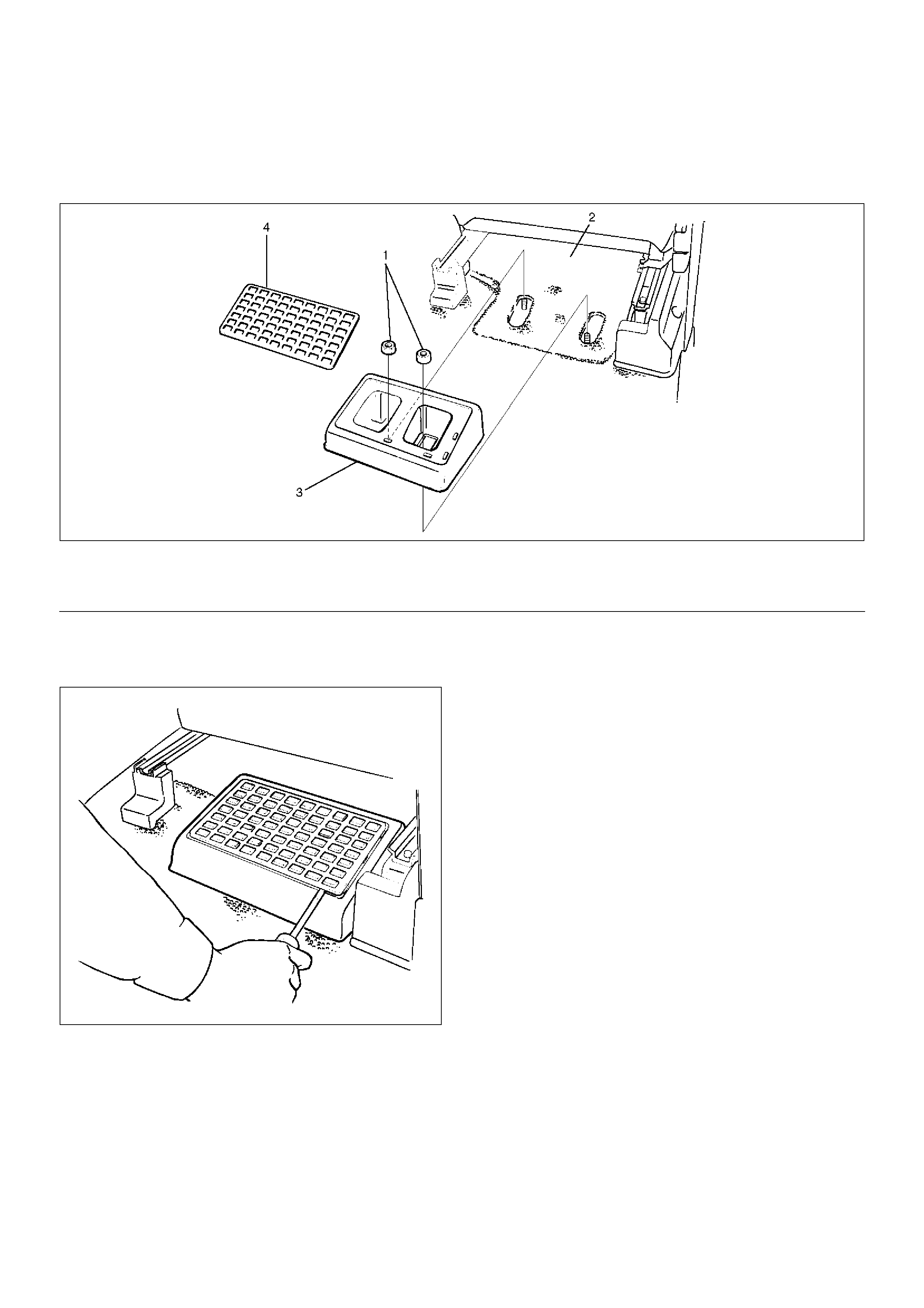
Rear Seat Foot Rest
Rear Seat Foot Rest and Associated Parts
676RY001
EndOFCallout
Removal
1. Remove the foot rest pad.
676RS002
2. Remove the fixing nuts.
3. Remove the rear seat foot rest.
Installation
To install, follow the removal steps in the reverse order.
Legend
(1) Fixing Nut
(2) Front Seat
(3) Rear Seat Foot Rest
(4) Foot Rest Pad
Main Data and Specifications
Torque Specifications
E10RX006
E10RW031