
SECTION 1C - EXTERIOR / INTERIOR TRIM
Service Precaution
Dash Side Trim Panel
Removal
Installation
Assist Grip
Parts Location
Removal and Installation
Consoles
Consoles and Associated Parts
Removal
Installation
Front Door Trim Panel
Front Door Trim Panel and Associated Parts
Removal
Installation
Rear Door Trim Panel
Rear Door Trim Panel and Associated Parts
Removal
Installation
Door Mirror
Door Mirror and Associated Parts
Removal
Installation
Luggage Side and Quarter Upper Trim Cover
Luggage Side, Quarter Upper Trim Cover and
Associated Parts
Removal
Installation
Centre Pillar and Roof Side Trim Cover
Center Pillar, Roof Side Trim Cover and Associated
Parts
Removal
Installation
Front Pillar Trim Cover
Front Pillar Trim Cover and Associated Parts
Removal
Installation
Center Pillar Assist Grip
Parts Location
Removal and Installation
Assist Grip
Parts Location
Removal and Installation
Fuel Filler Lid Opener Cable
Fuel Filler Lid Opener Cable and Associated Parts
Removal
Installation
Fuel Filler Door
Parts Location
Removal
Installation
Rocker Protector (Without Wheel Opening Extension)
Rocker Protector (Without Wheel Opening
Extension) and Associated Parts
Removal
Installation
Wheel Opening Extension and Rocker Protector
Assembly
Wheel Opening Extension, Rocker Protector
Assembly and Associated Parts
Removal
Installation
Mud Flaps (With Wheel Opening Extension)
Mud Flaps (With Wheel Opening Extension) and
Associated Parts
Removal
Installation
Ventilation Assembly
Ventilation Assembly and Associated Parts
Removal
Installation
Quarter Flipper Glass Assembly (SWB)
Quarter Flipper Glass Assembly and Associated
Parts
Removal
Installation
Tailgate Trim Panel (LH)
Tailgate Trim Panel (LH) and Associated Parts
Removal
Installation
Tailgate Trim Panel (RH)
Parts Location
Removal
Installation
Luggage Floor Box
Luggage Floor Box and Associated Parts
Remove
Installation
Rope Hook Set
Rope Hook Set and Associated Parts
Removal
Installation
Power Door Mirror System
General Description
Door Mirror Switch Assembly (Control Switch,
Folding Switch and Defogger Switch) Removal
Installation
Power Door Mirror
General Description
Removal and Installation
Power Window System
General Description
Power Window Switch Removal and Installation
Power Window Motor Removal and Installation
Main Data and Specifications
Techline
Techline
Techline

Service Precaution
WARNING: IF SO EQUIPPED WITH A
SUPPLEMENTAL RESTRAINT SYSTEM (SRS),
REFER TO THE SRS COMPONENT AND WIRING
LOCATION VIEW IN ORDER TO DETERMINE
WHETHER YOU ARE PERFORMING SERVICE ON
OR NEAR THE SRS COMPONENTS OR THE SRS
WIRING. WHEN YOU ARE PERFORMING SERVICE
ON OR NEAR THE SRS COMPONENTS OR THE
SRS WIRING, REFER TO THE SRS SERVICE
INFORMATION. FAILURE TO FOLLOW WARNINGS
COULD RESULT IN POSSIBLE AIR BAG
DEPLOYMENT, PERSONAL INJURY, OR
OTHERWISE UNNEEDED SRS SYSTEM REPAIRS.
CAUTION: Always use the correct fastener in the
proper location. When you replace a fastener, use
ONLY the exact part number for that application.
HOLDEN will call out those fasteners that require a
replacement after removal. HOLDEN will also call
out the fasteners that require thread lockers or
thread sealant. UNLESS OTHERWISE SPECIFIED,
do not use supplemental coatings (Paints, greases,
or other corrosion inhibitors) on threaded fasteners
or fastener joint interfaces. Generally, such
coatings adversely affect the fastener torque and
the joint clamping force, and may damage the
fastener. When you install fasteners, use the correct
tightening sequence and specifications. Following
these instructions can help you avoid damage to
parts and systems.

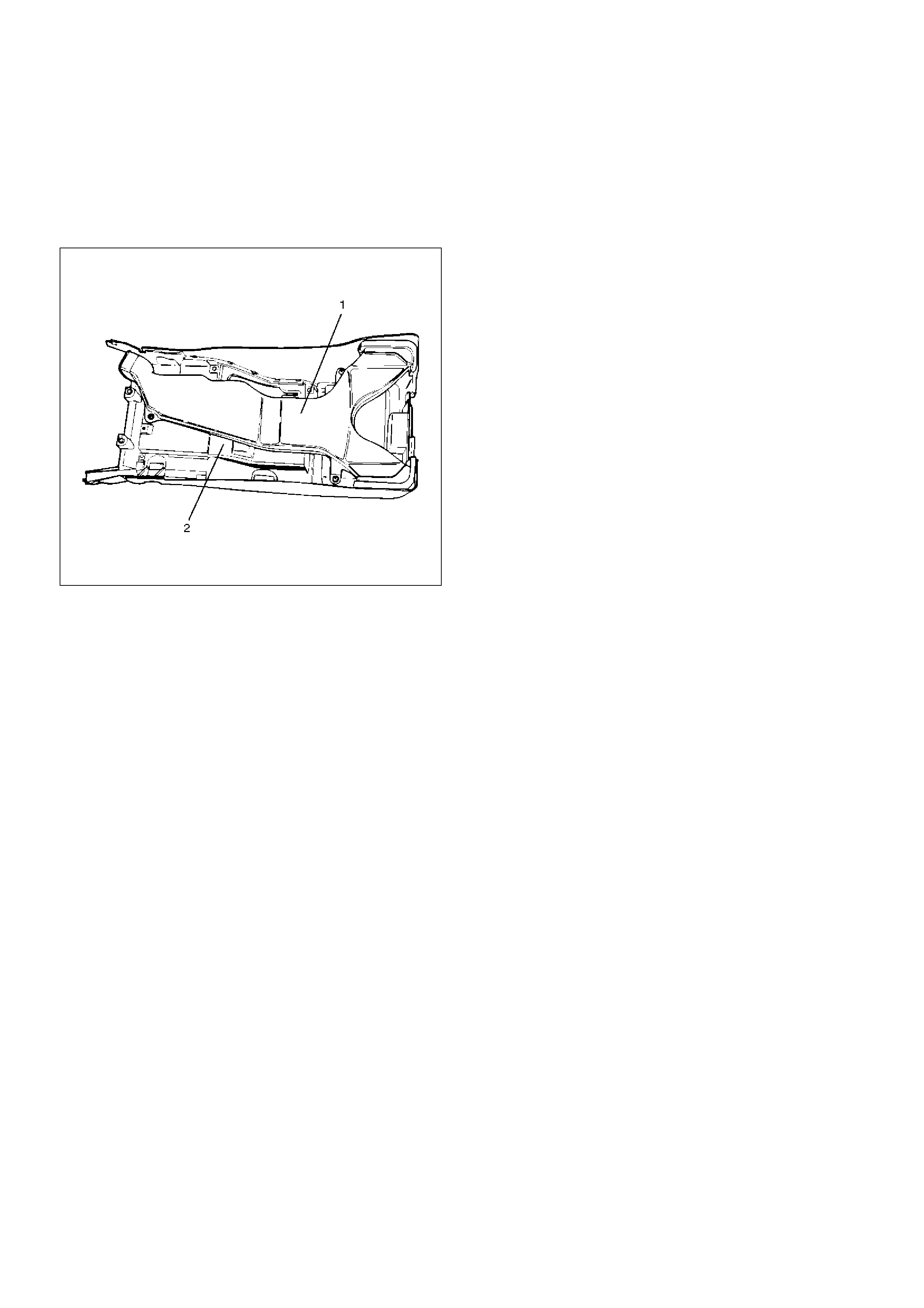
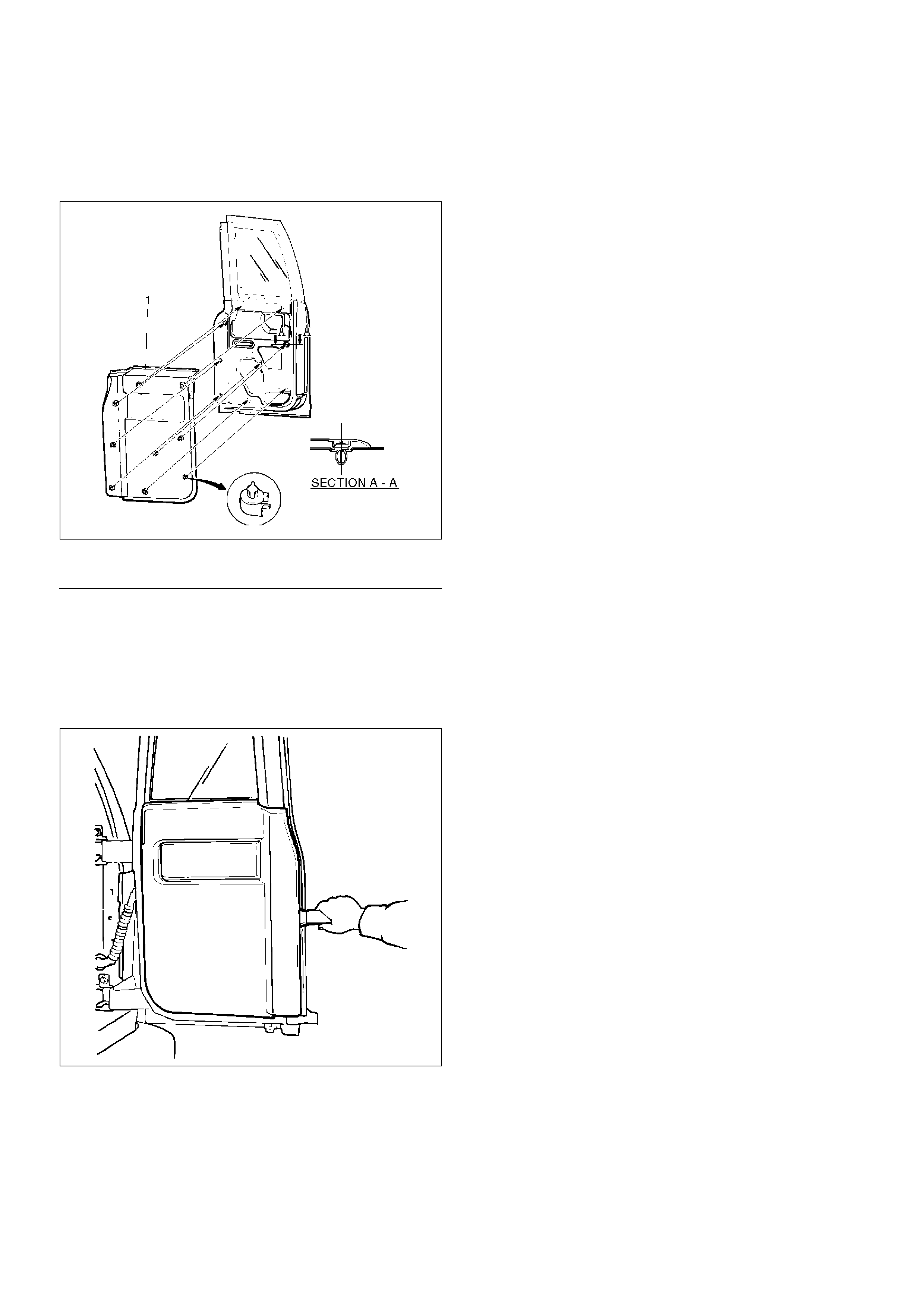
Dash Side Trim Panel
Removal
1.Disconnect the battery ground cable.
2.Remove the front door sill plate(2).
3.Remove the dash side trim panel(3).
•Turn up the door inner seal(1) of the body panel
to remove the clips of the trim panel.
•Take care not to damage the harness and the
controller on the back of the trim panel.
643RW005
Installation
To install, follow the removal steps in the reverse order,
noting the following point.
1.Lap the door inner seal over the trim panel to install
them securely to the body panel.
Assist Grip
Parts Location
745RW006
EndOFCallout
Removal and Installation
•Refer to the Consoles in this section.
Legend
(1) Assist Grip
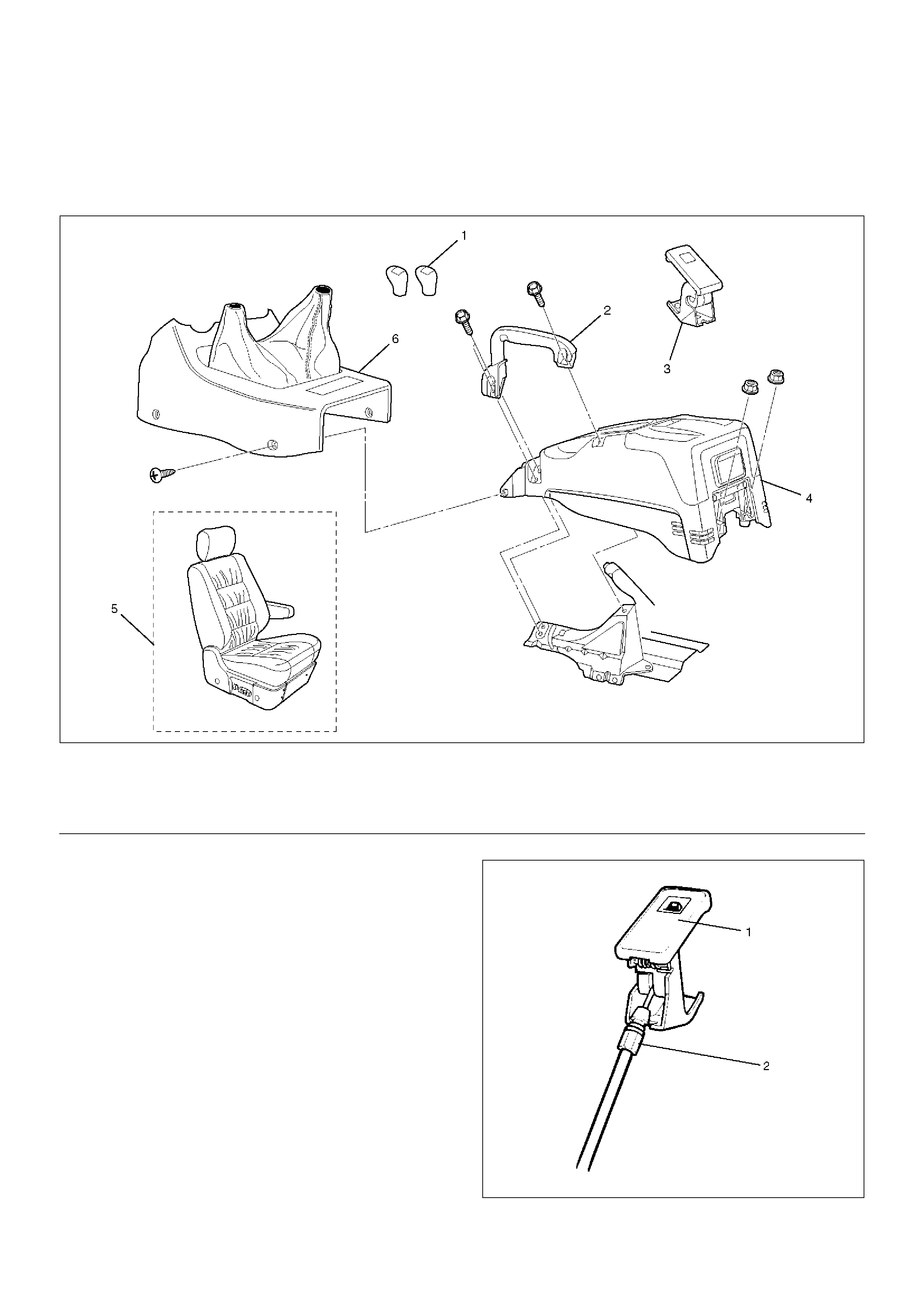
Consoles
Consoles and Associated Parts
This illustration is based on RHD
745RW009
EndOFCallout
Removal
1.Disconnect the battery ground cable.
2.Remove the shift knob (M/T) / transfer knob (A/T).
3.Remove the front console assembly.
•Remove four fixing screws and disconnect the
switch connectors.
4.Remove the front seat assembly(RH).
•Refer to the Front Seat Assembly in Seats
section.
5. Remove the assist grip.
• Remove three bolts.
6. Remove the fuel filler lid opener.
• Remove the fuel filter lid opener(1) and
disconnect the cable(2).
686RW007
Legend
(1) Shift Knob (M/T) / Transfer Knob (A/T)
(2) Assist Grip
(3) Fuel Filler Lid Opener
(4) Center Console Assembly
(5) Front Seat Assembly (RH)
(6) Front Console Assembly
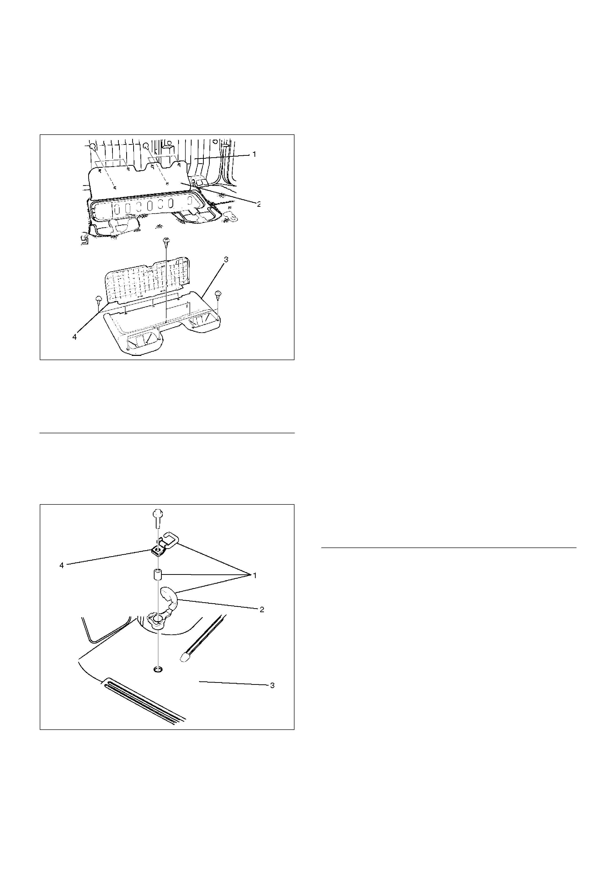
7. Remove the center console assembly(2).
• Remove two fixing screws on the front side.
Open the rear cover, remove two nuts, then the
center console assembly.
• Remove the rear heater duct(1) from the center
console.
745RS005
Installation
To install, follow the removal steps in the reverse order.
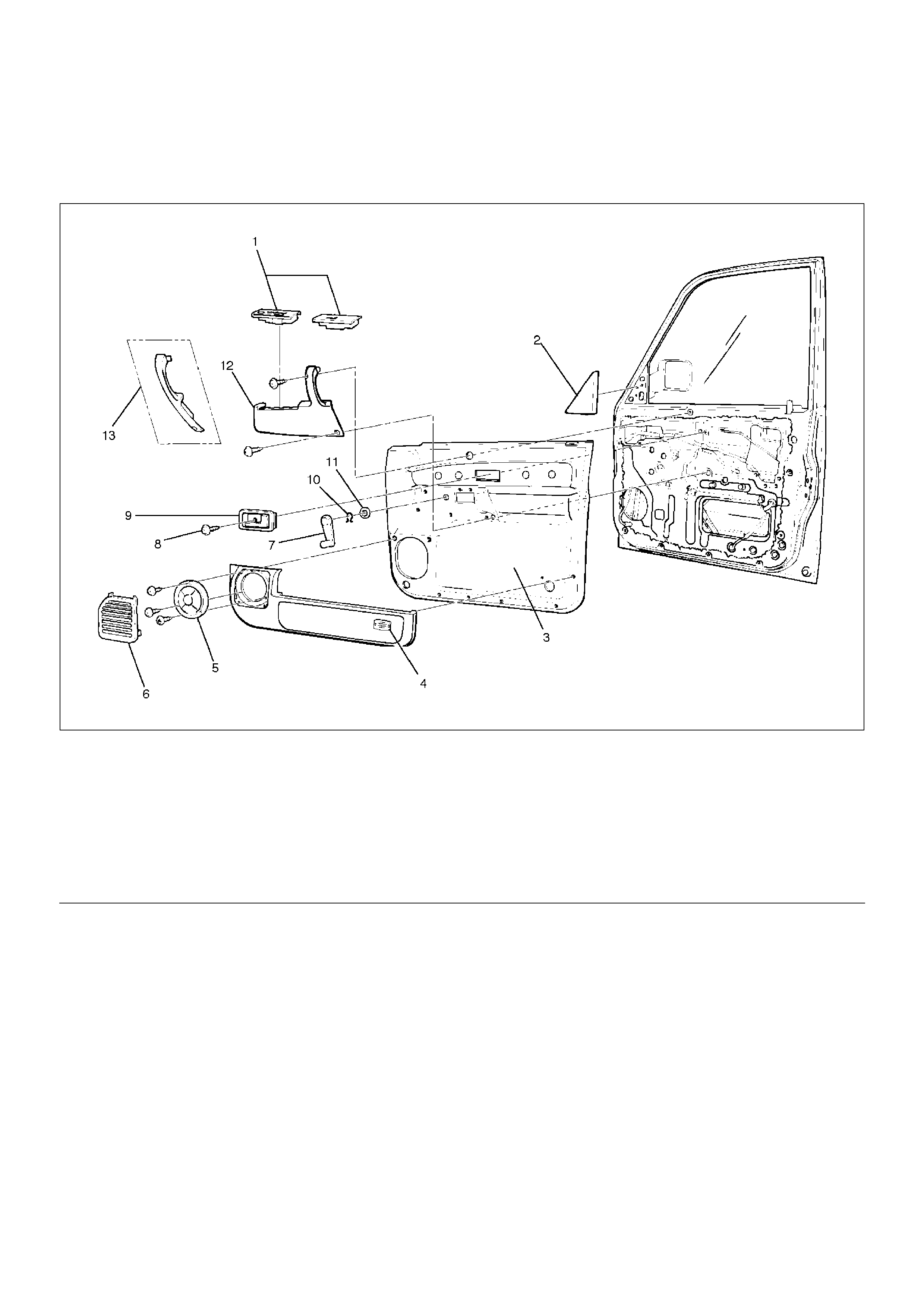
Front Door Trim Panel
Front Door Trim Panel and Associated Parts
635RW011
EndOFCallout
Removal
1. Disconnect the battery ground cable.
Legend
(1) Power Window Switch
(2) Door Mirror Cover
(3) Door Trim Panel
(4) Courtesy Light
(5) Front Speaker
(6) Speaker Cover
(7) Regulator Handle
(8) Inside Handle Fixing Screw
(9) Inside Handle
(10) Hook
(11) Washer
(12) Inside Pull Handle
(13) Inside Pull Handle (W/O Power Window)
2.Remove the door mirror cover (1).
720RW011
3.Remove the regulator handle(3).
•Pull the hook(4) out and remove the regulator
handle.
631RW001
4.Remove the power window switch(1).
•Pry the power window switch out and disconnect
the switch connector.
825RW174
5.Remove the speaker cover.
6.Remove the front speaker.
•Remove the front speaker fixing screws in order
to disconnect the speaker connector.
7.Remove the inside handle fixing screw.
•Remove the screw that fixes the inside handle(7),
slide the inside handle to the position illustrated,
and leave it there for the moment.
CAUTION: Take care not to impose excessive force
on the inside handle link(6), lest this link is
elongated, which could make it impossible to
operate the door with the inside handle.
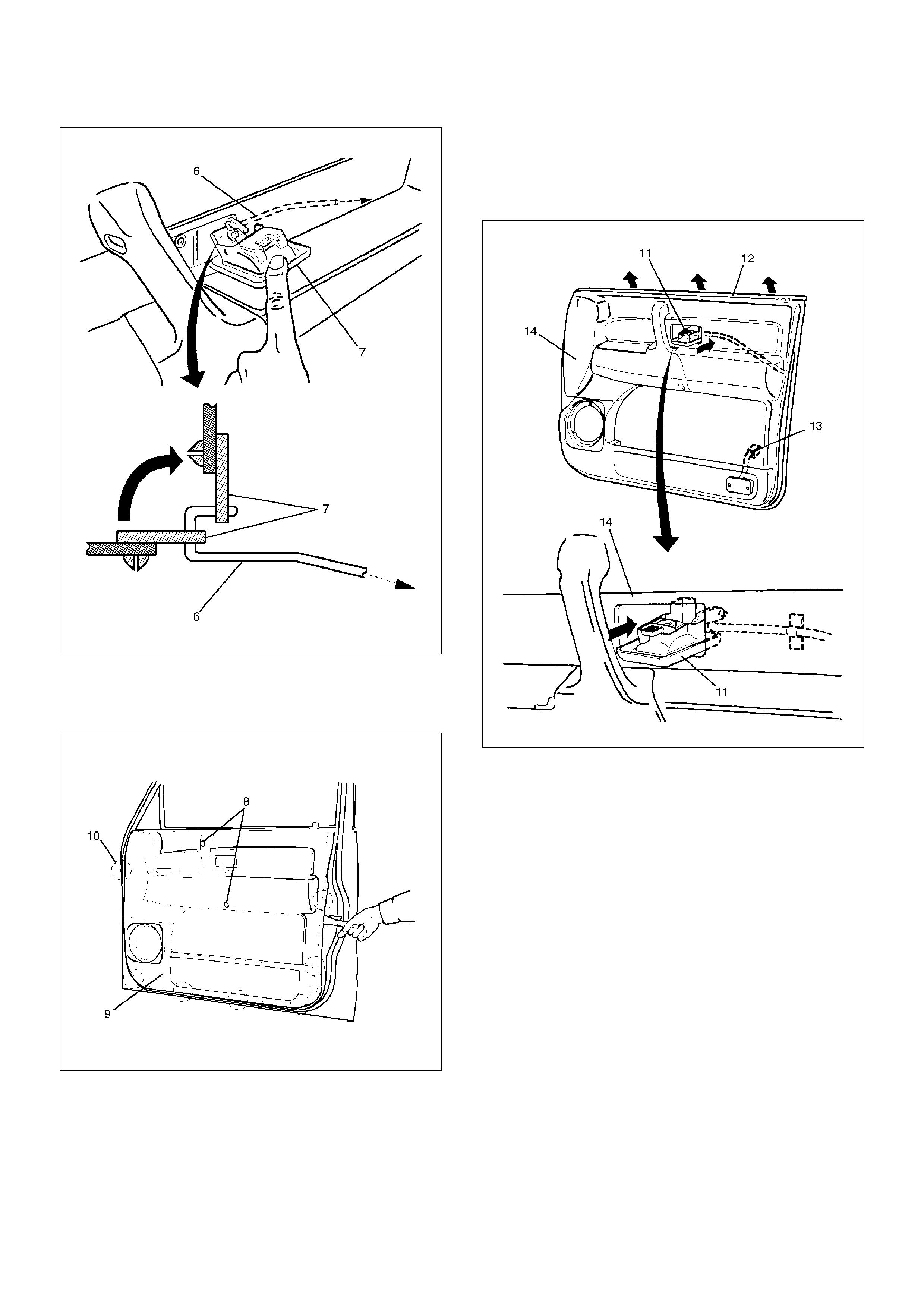
632RW001
8. Remove the door trim panel(9).
• Remove two fixing screws(8) in order to take off
seven clips(10) from the door panel.
635RS007
• Disconnect the courtesy light connector(13) to lift
the door trim panel(14) and unlock the
engagement of the waist seal(12) section. Then,
pass the inside handle(11) through the mounting
hole of the trim panel, and detach the trim panel.
632RS015
9. Remove the inside handle.
Installation
To install, follow the removal steps in the reverse order,
noting the following point.
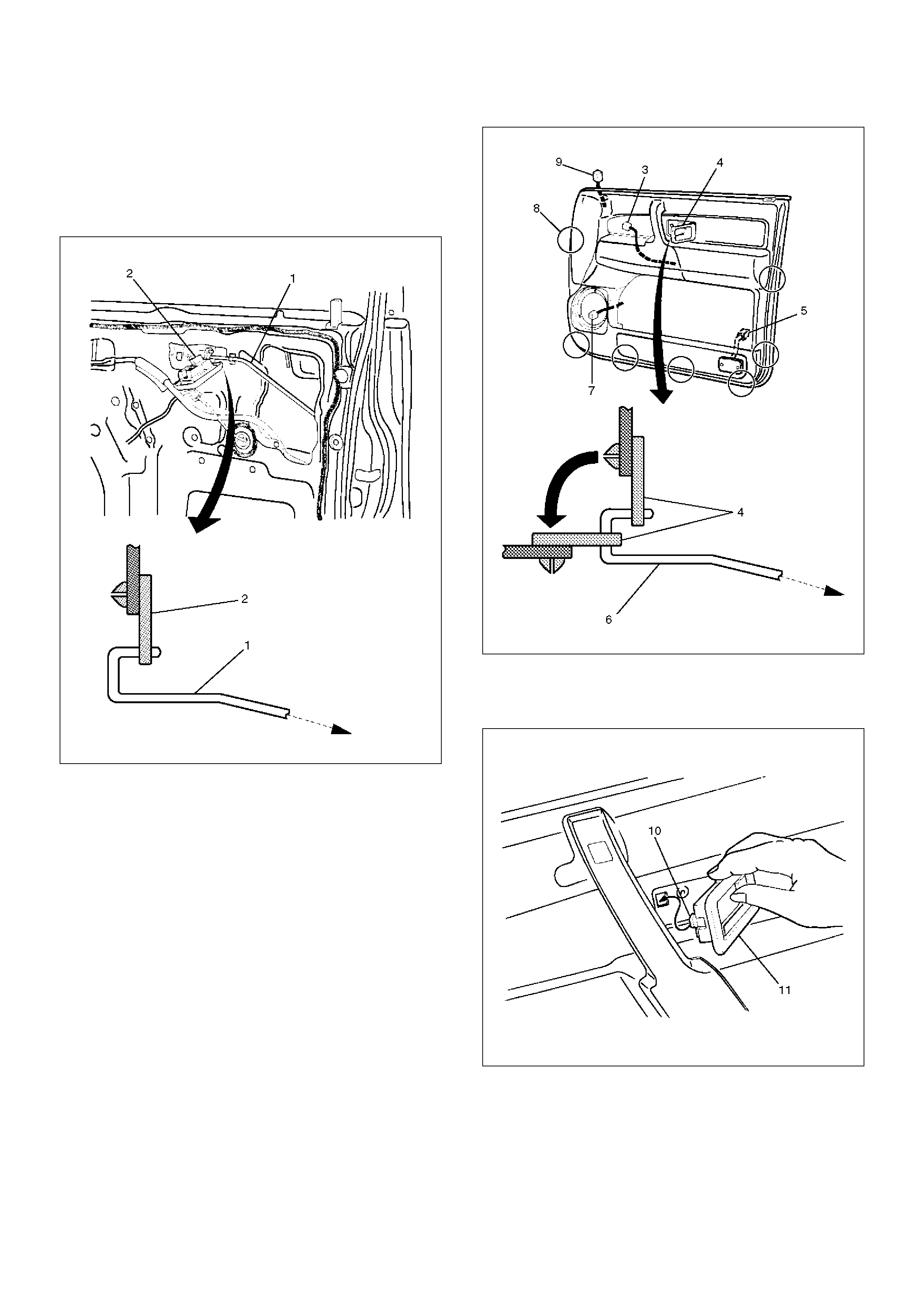
1. When installing the inside handle(2), assemble it
temporarily to the inside handle link(1).
632RS014
2. Pass the inside handle(4) through the mounting
hole of the trim panel and assemble the trim panel.
Engage seven clips(8) into the door panel. Also,
connect the courtesy light connector(5) and leave
the connectors of the speaker(7), tweeter(9) and
power window(3) drawn out to their prescribed
positions, so that they will not be caught.
Then, put the inside handle(4) to the normal position
of the inside handle link(6).
632RW006
3. Fit the claw(10) of the inside handle(11) securely
into the hole of the door panel and fix the inside
handle with the screw.
632RW007
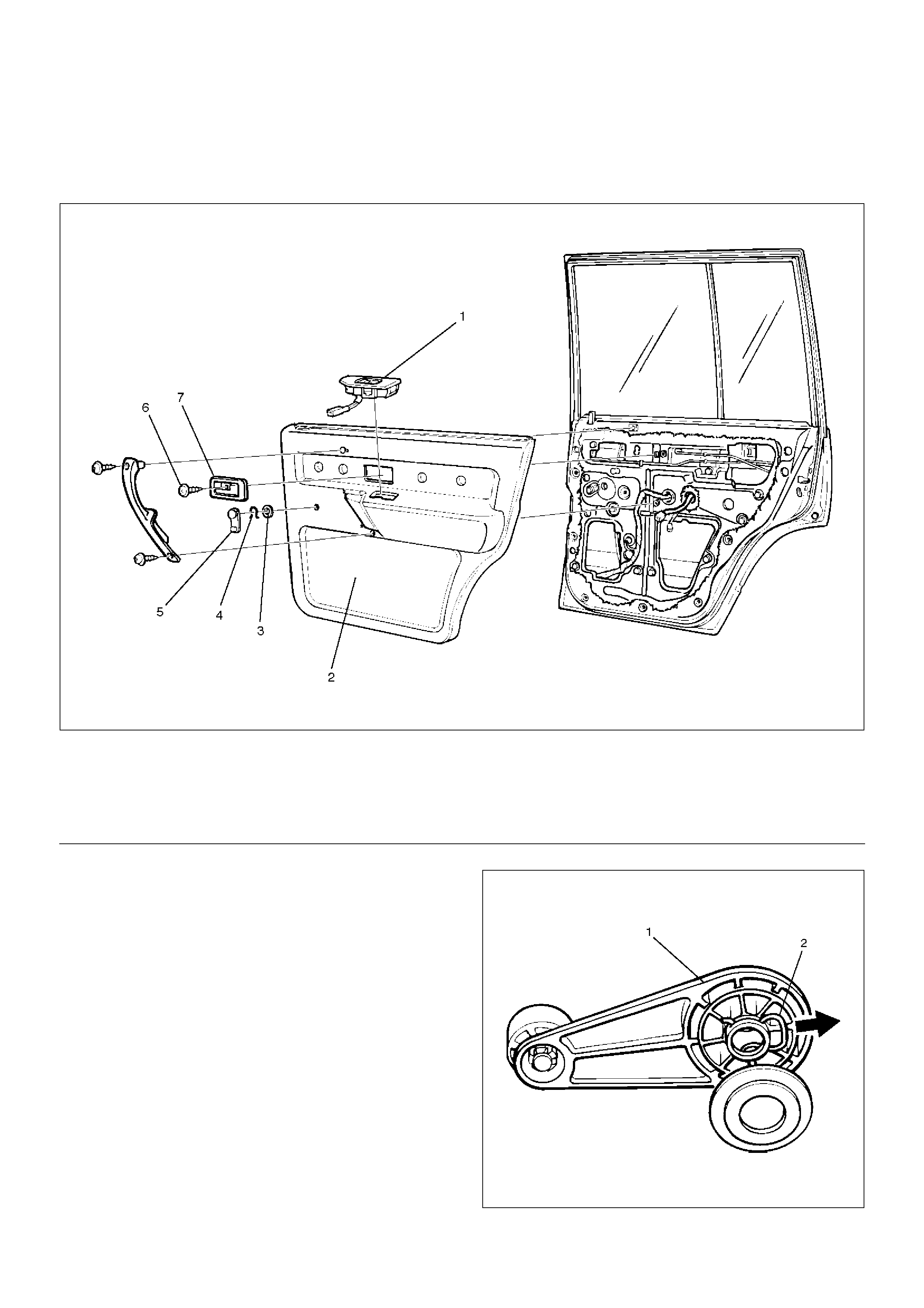
Rear Door Trim Panel
Rear Door Trim Panel and Associated Parts
655RW006
EndOFCallout
Removal
1. Disconnect the battery ground cable.
2. Remove the regulator handle(1).
• Pull the hook(2) out and remove the regulator
handle.
631RW002
3. Remove the power window switch(3).
Legend
(1) Power Window Switch
(2) Door Trim Panel
(3) Washer
(4) Clip
(5) Regulator Handle
(6) Inside Handle Fixing Screw
(7) Inside Handle
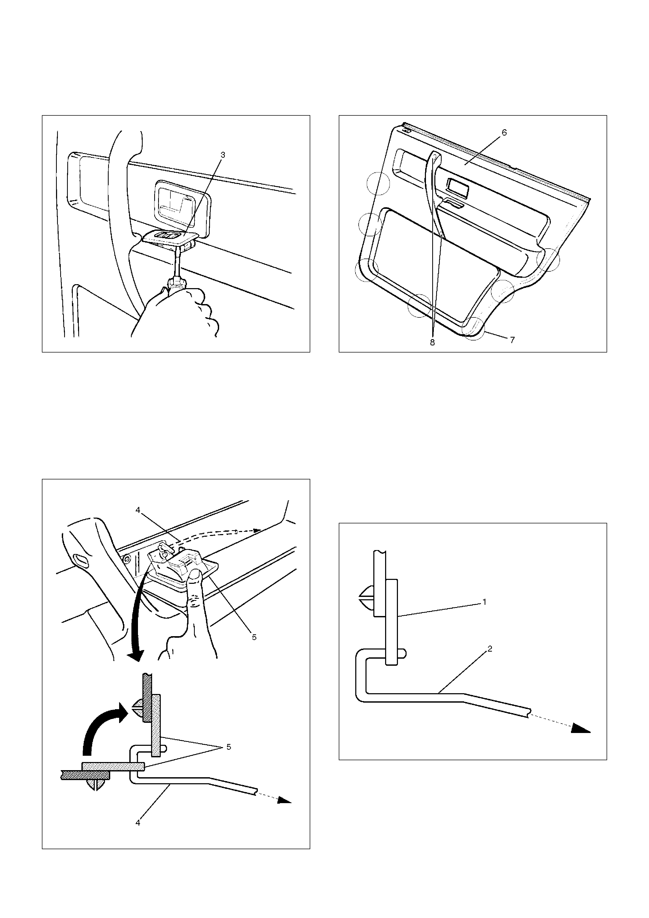
•Pry the power window switch out and disconnect
the switch connector.
825RS084
4.Remove the inside handle fixing screw.
•Remove the screw that fixes the inside handle(5),
slide the inside handle to the position illustrated,
and leave it there for the moment.
CAUTION: Take care not to impose excessive force
on the inside handle link(4), lest this link be
elongated, which could make it impossible to
operate the door with the inside handle.
632RW002
5. Remove the door trim panel(6).
• Remove two fixing screws(8) to take off seven
clips(7) from the door panel.
655RW007
• Lift the trim panel and unlock the engagement of
the waist seal section. Then, pass the inside lever
through the mounting hole of the trim panel, and
detach the trim panel.
6. Remove the inside handle.
Installation
To install, follow the removal steps in the reverse order,
noting the following point.
1. When installing the inside handle(1), assemble
temporarily to the inside handle link(2).
652RS006
2. Pass the inside handle through the mounting hole of
the trim panel. Assemble the trim panel. Engage
securely seven clips into the door panel. Also, leave
the connector of the power window drawn out to its
prescribed position, so that it will not caught.
3. Put back the inside handle(3) to the original position
of the link(5). Fit the claw(4) of the inside handle
securely into the hole of the door panel. Fix the
handle with the screw.
632RW011
Door Mirror
Door Mirror and Associated Parts
720RS012
EndOFCallout
Removal
1. Disconnect the battery ground cable.
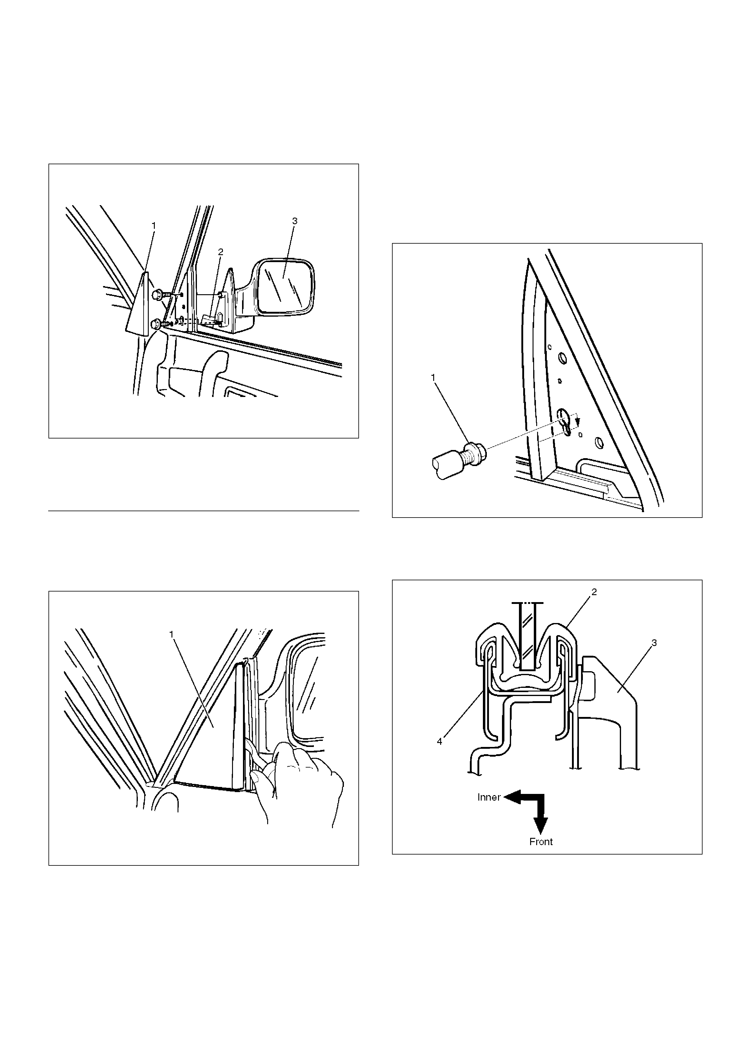
2. Remove the door mirror cover(1).
720RW011
3. Remove the door mirror connector.
4. Remove the door mirror.
Installation
To install, follow the removal steps in the reverse order,
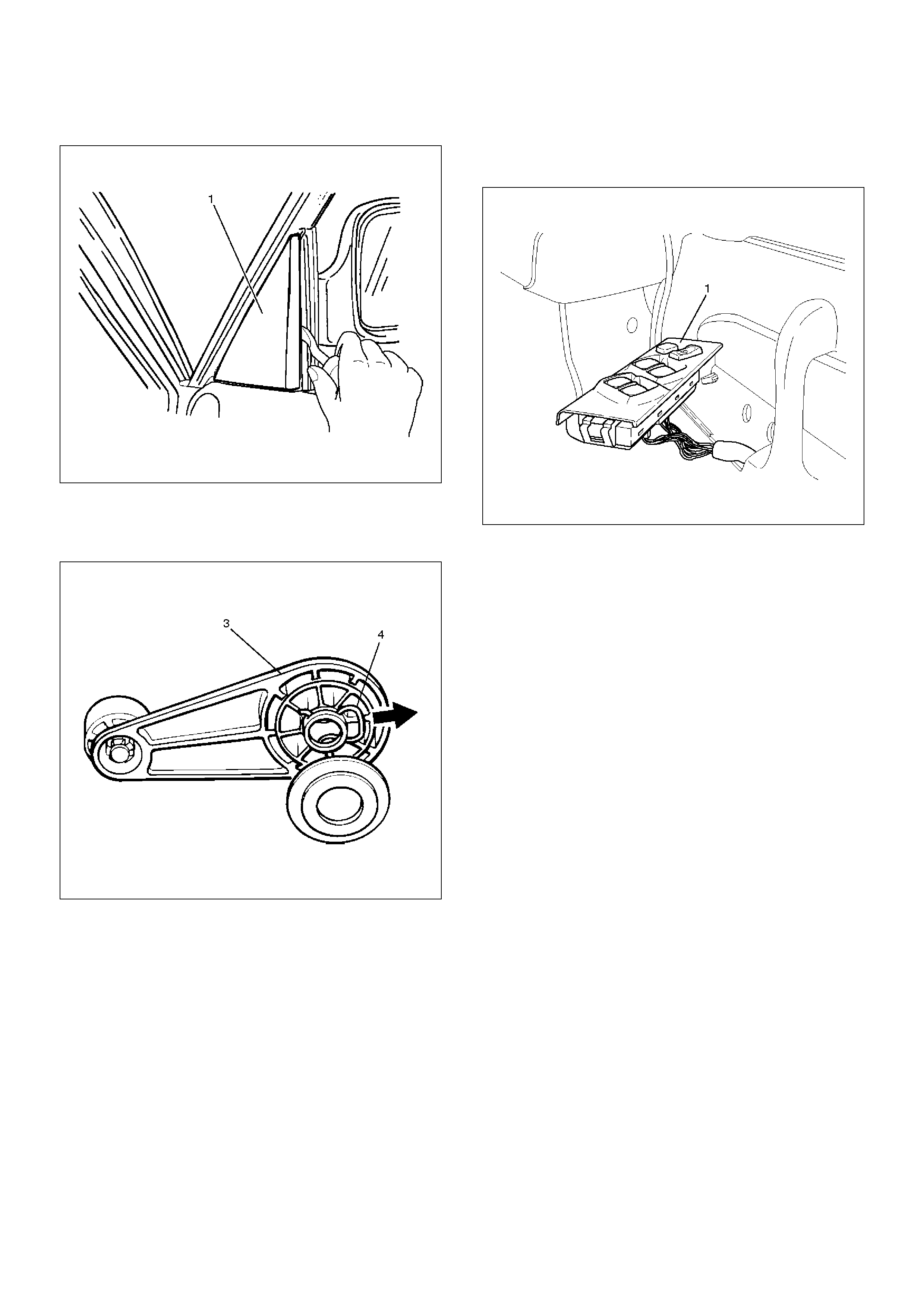
noting the following points.
1. When you install the door mirror, install the bolt(1) to
the mirror temporarily, hook the bolt to the door side
hole and tighten the bolt from the inside.
720RS001
2. When installing the door mirror, hold the glass run
lip(2) between the door mirror base(3) and the
center sash(4).
A10RS001
3. Tighten the door mirror fixing bolts to the specified
torque.
Torque: 8N·m (0.8kg·m/69lbin)
Legend
(1) Door Mirror Cover
(2) Door Mirror Connector
(3) Door Mirror
Luggage Side and Quarter Upper Trim Cover
Luggage Side, Quarter Upper Trim Cover and Associated Parts
760RW017
EndOFCallout
Removal
1. Disconnect the battery ground cable.
2. Remove the third seat assembly and seat bracket.
3. Remove the rear end floor trim cover.
4. Remove the luggage side cap.
5. Remove the luggage side lower cover.
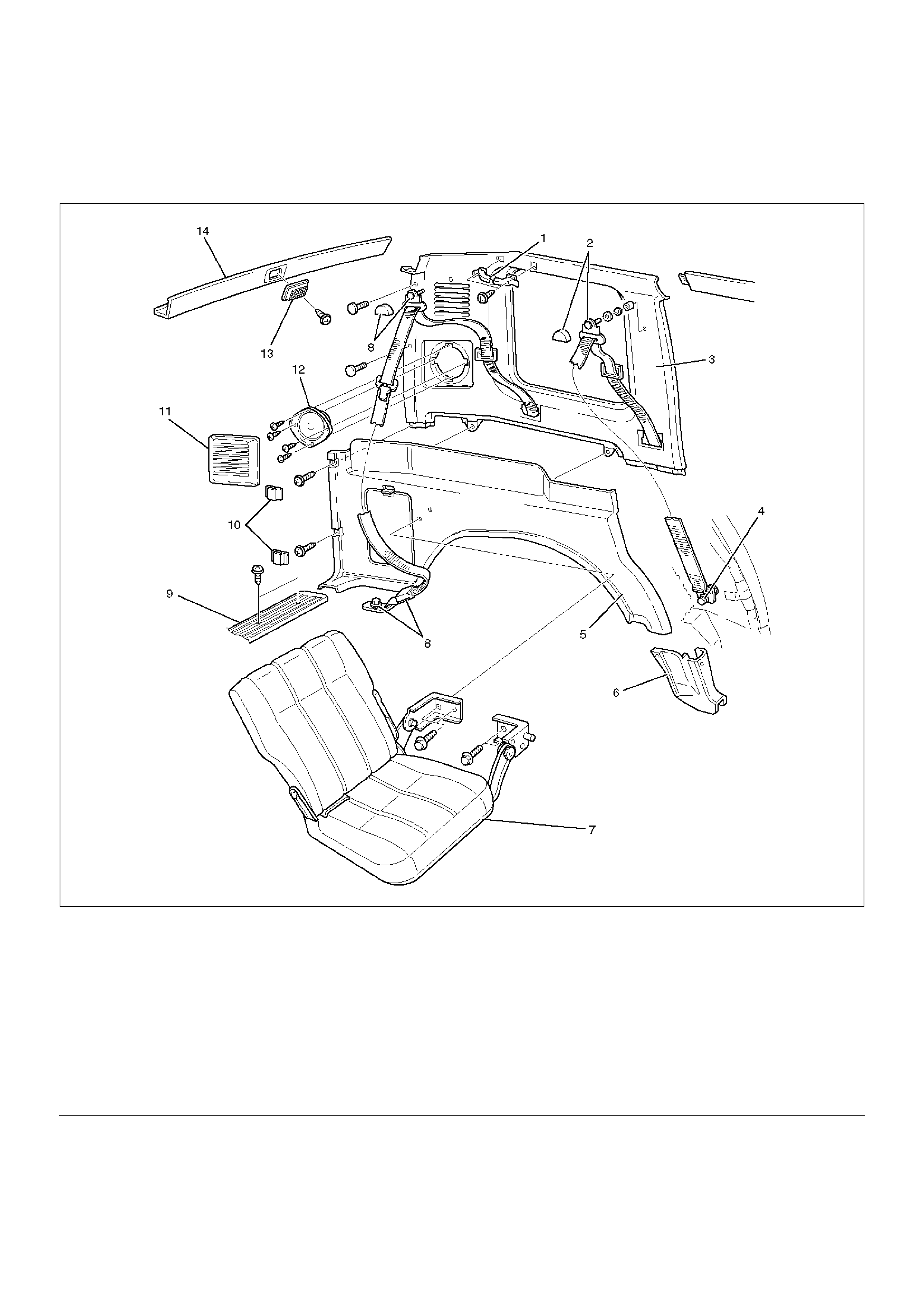
6. Remove the luggage side trim cover (1).
Legend
(1) Assist Grip
(2) Rear Seat Belt Anchor Bolt Cover and Anchor
Bolt
(3) Quarter Upper Trim Cover
(4) Anchor Bolt
(5) Luggage Side Trim Cover
(6) Luggage Side Lower Cover
(7) Third Seat Assembly and seat Bracket
(8) Third Seat Belt Anchor Bolt Cover and Anchor
Bolt
(9) Rear End Floor Trim Cover
(10) Luggage Side Cap
(11) Speaker Grille
(12) Rear Speaker
(13) Luggage Room Light
(14) Rear Roof Trim Cover
•Remove the rear side fixing screws and pry the
trim cover retainers free from the body panel and
the upper trim cover.
687RS002
7.Remove the luggage room light.
•Remove the luggage room light lens and the
fixing screws.
•Disconnect the luggage room light connector.
8.Remove the rear roof trim cover.
•Pry the trim cover retainers free from the body
panel.
666RS001
9.Remove the speaker grille.
687RS003
10.Remove the rear speaker.
•Remove the rear speaker fixing screws and
disconnect the connector.
11.Remove the rear seat belt anchor bolt cover (2) and
the anchor bolt (3).
760RW005
12.Remove the third seat belt anchor bolt cover and
anchor bolt.
•Refer to the Third Seat Belt removal procedure in
Seat Belt System section.
13. Remove the assist grip.
14. Remove the quarter upper trim cover.
• Remove the rear side clips of the trim cover and
pry the quarter upper trim cover retainers free
from the body panel.
687RS004
Installation
To install, follow the removal steps in the reverse order,
noting the following point.
1. Tighten the seat belt anchor bolt to the specified
torque.
Torque: 39N·m (4.0kg·m/29lbft)
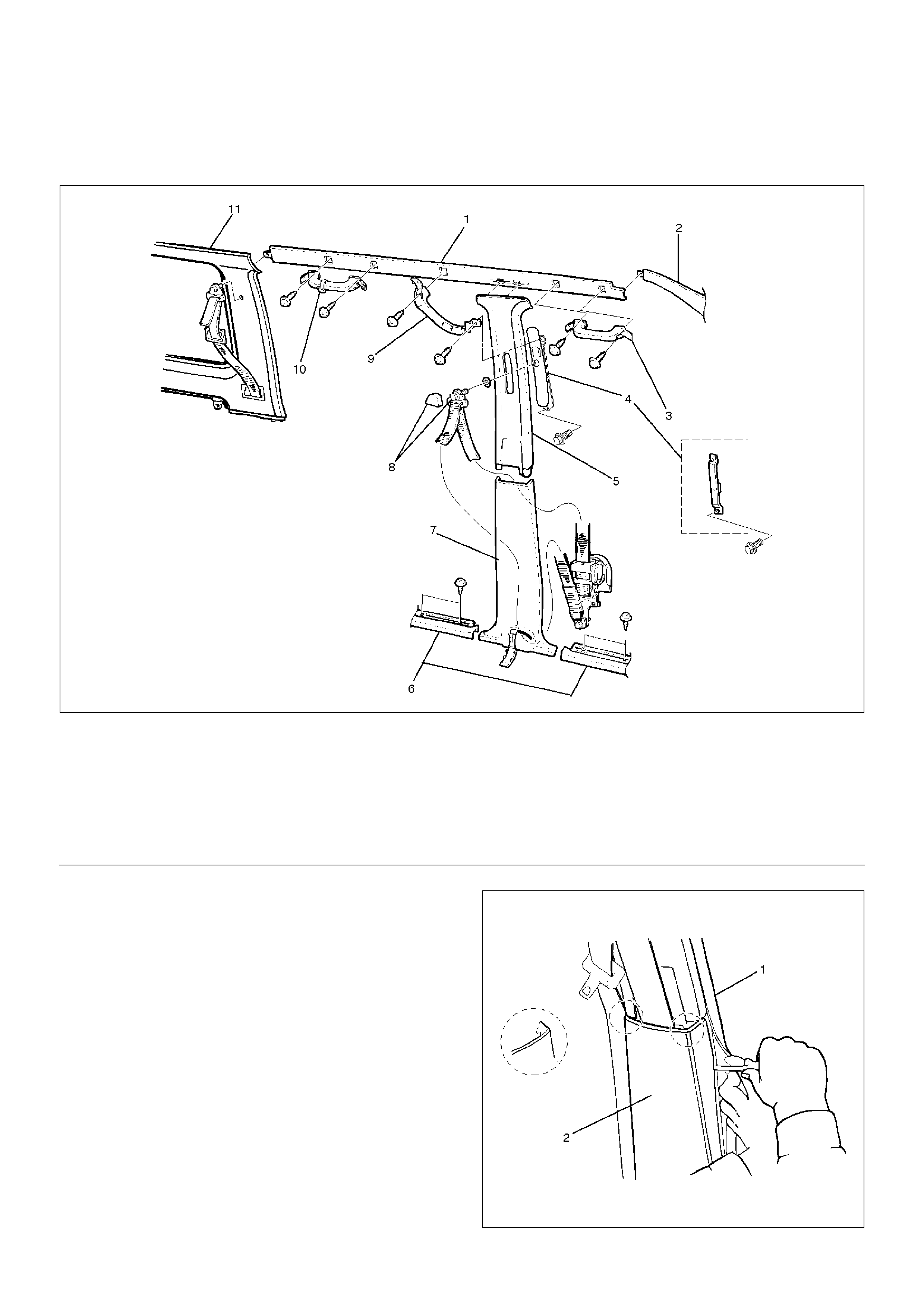
Centre Pillar and Roof Side Trim Cover
Center Pillar, Roof Side Trim Cover and Associated Parts
643RW007
EndOFCallout
Removal
1. Disconnect the battery ground cable.
2. Remove the door sill plate (front and rear).
3. Remove the center pillar lower trim cover (2).
• Turn up the finisher (1) and pry the trim cover
retainers free from the body panel, then slide the
trim cover downward.
643RS003
Legend
(1) Roof Side Trim Cover
(2) Front Pillar Trim Cover
(3) Assist Grip (Passenger Seat Side)
(4) Adjust Shoulder Anchor Assembly/Seat Belt
Anchor Plate
(5) Center Pillar Upper Trim Plate
(6) Door Sill Plate (Front and Rear)
(7) Center Pillar Lower Trim Cover
(8) Front Seat Anchor Bolt Cover and Anchor Bolt
(9) Center Pillar Assist Grip
(10) Assist Grip
(11) Rear Quarter Upper Trim Cover
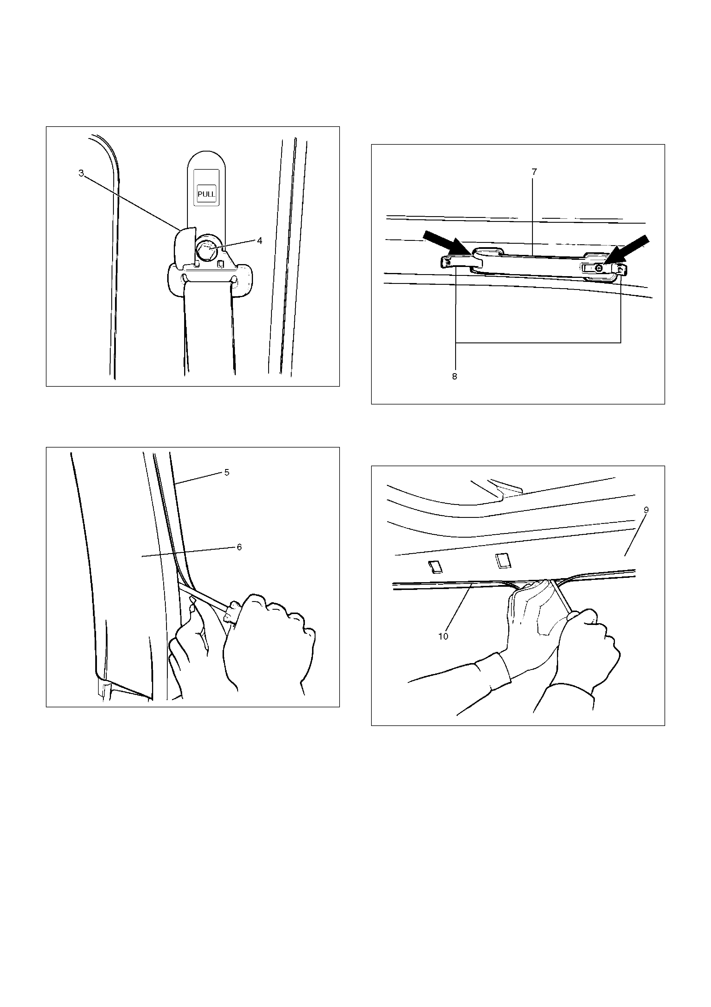
4. Remove the front seat belt anchor bolt cover (3) and
the anchor bolt (4).
760RW006
5. Remove the center pillar upper trim cover (6).
• Turn up the finisher (5) and pry the trim cover
retainers free from the body panel.
643RS004
6. Remove the center pillar assist grip.
7. Remove the seat belt anchor plate/adjusut shoulder
anchor assembly.
8. Remove the assist grip (7).
• Open the both side of the assist grip cover (8)
and remove two fixing screws.
743RW004
9. Remove the roof side trim cover (9).
• Turn up the finisher (10) and pry the trim cover
retainers free from the body panel.
643RS005
Installation
To install, follow the removal steps in the reverse order,
noting the following point.
1. Install the seat belt anchor bolts to the specified
torque.
Torque: 39N·m (4.0kg·m/29lbft)
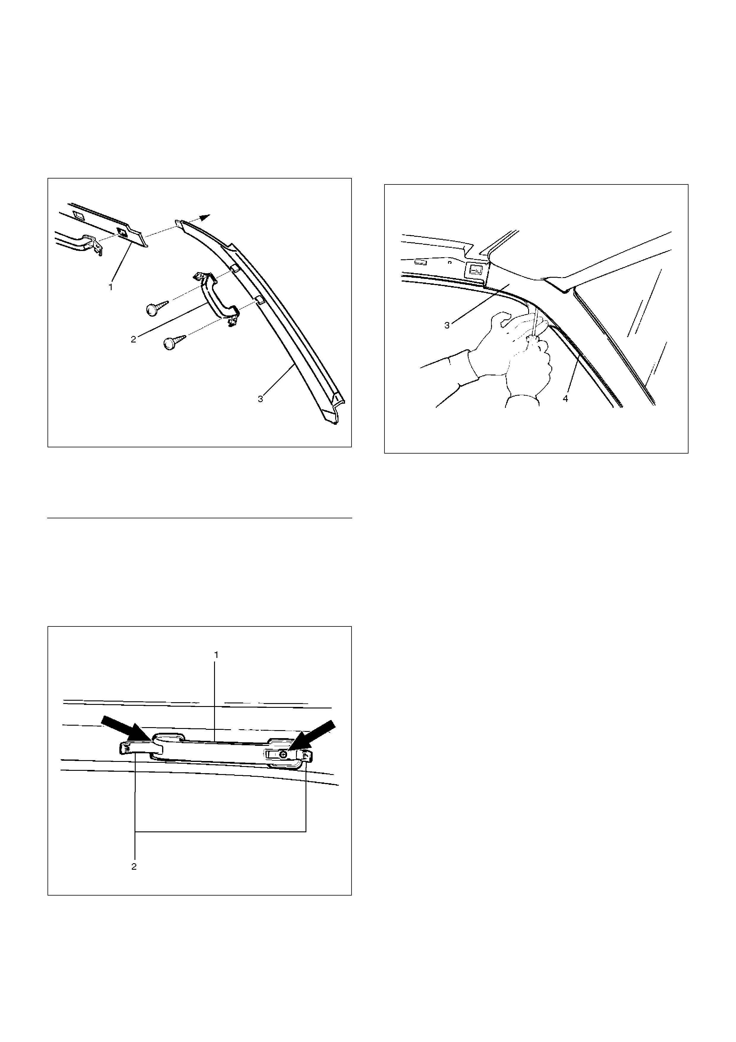
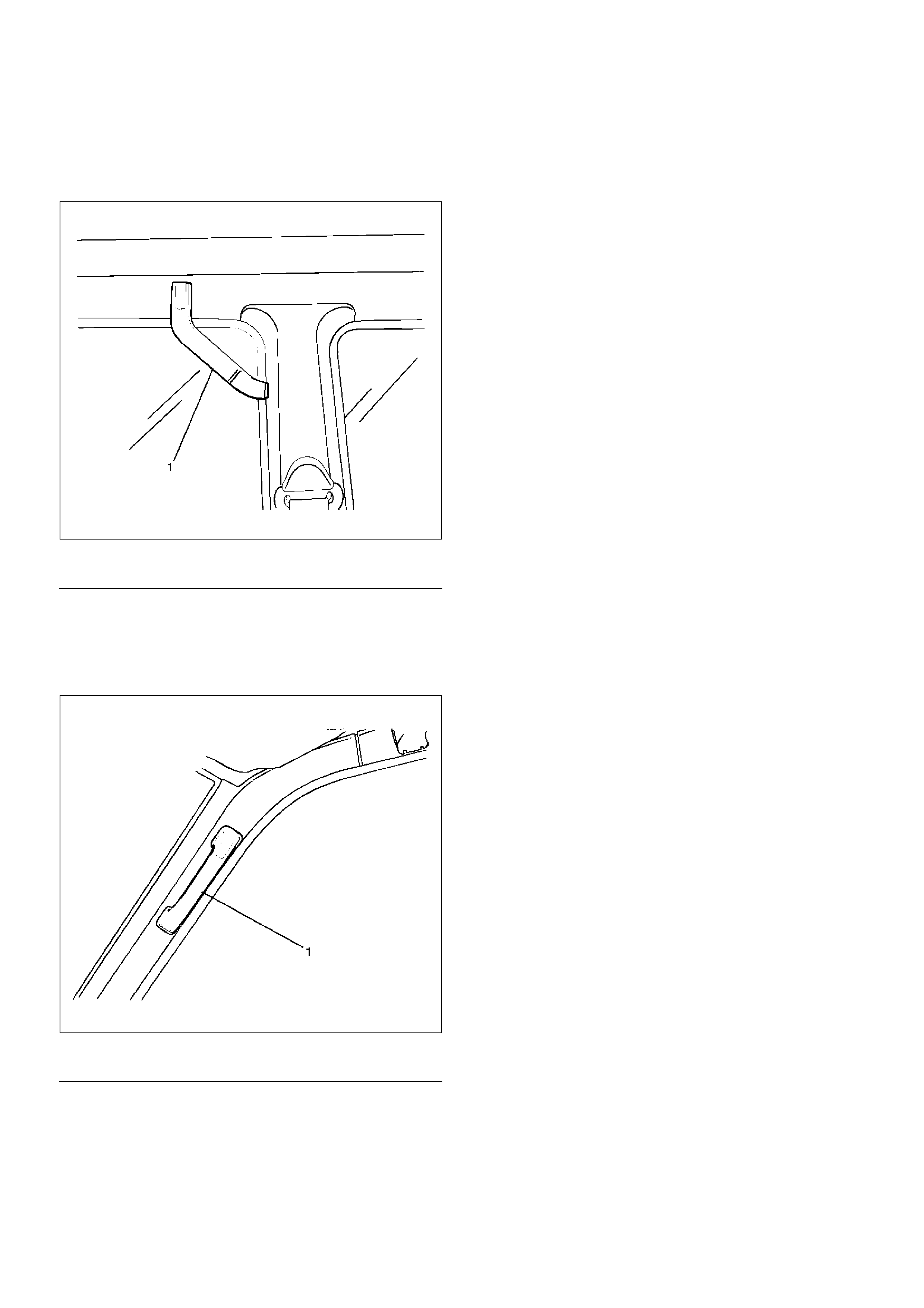
Front Pillar Trim Cover
Front Pillar Trim Cover and Associated
Parts
743RS003
EndOFCallout
Removal
1. Remove the front pillar assist grip(1).
• Open the both sides of the assist grip cover (2)
and remove the fixing screws and the front pillar
assist grip.
743RW003
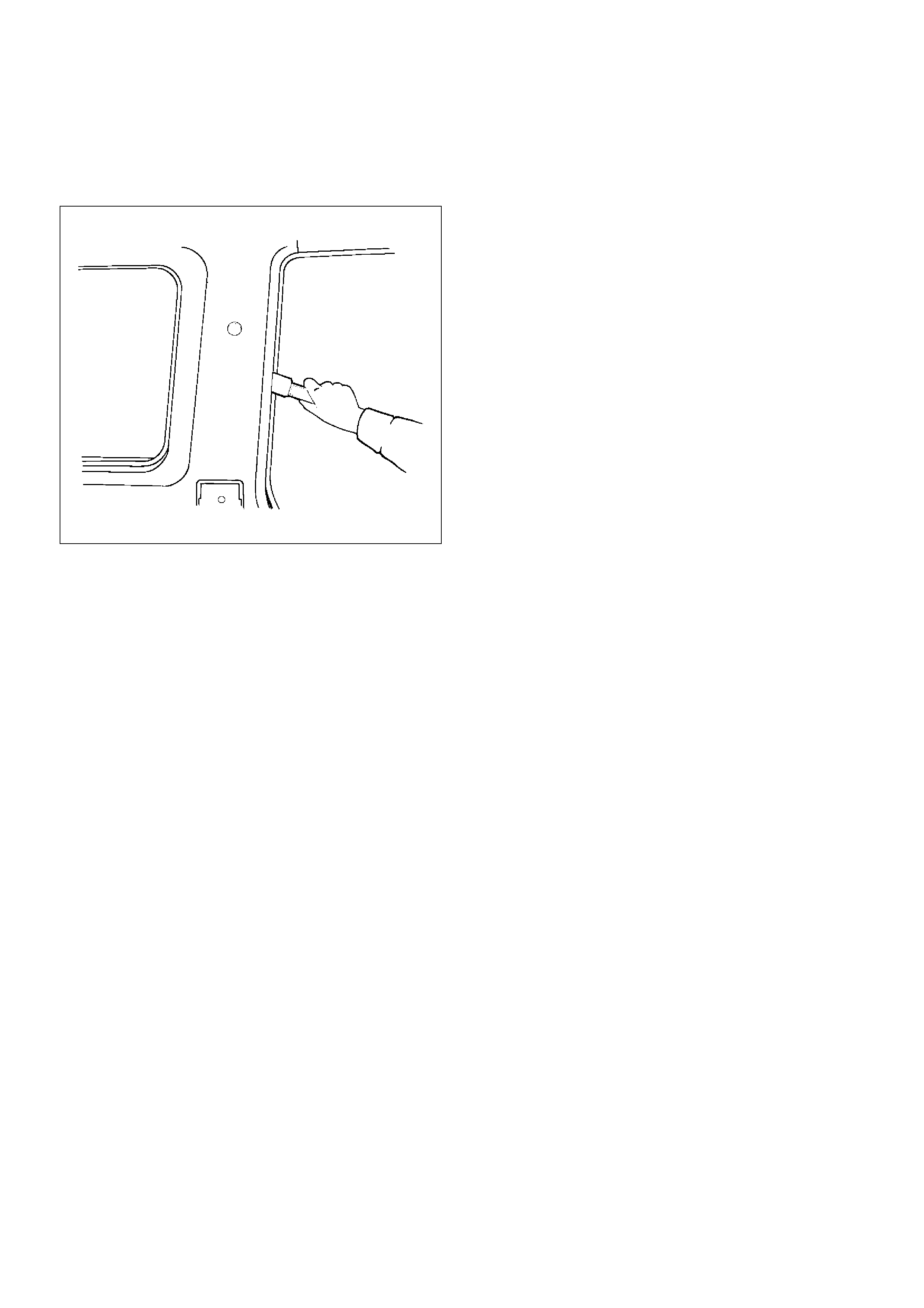
2. Remove the front pillar trim cover (3).
• Turn up the finisher (4) and pry the trim cover
retainers free from the body panel.
635RW001
Installation
To install, follow the removal steps in the reverse order.
Legend
(1) Roof Side Trim Panel
(2) Assist Grip
(3) Front Pillar Trim Panel
Center Pillar Assist Grip
Parts Location
743RS004
EndOFCallout
Removal and Installation
Refer to the Center Pillar and Roof Side Trim Cover in
this section.
Assist Grip
Parts Location
743RS005
EndOFCallout
Removal and Installation
Refer to the Front Pillar Trim Cover in this section.
Legend
(1) Center Pillar Assist Grip
Legend
(1) Assist Grip
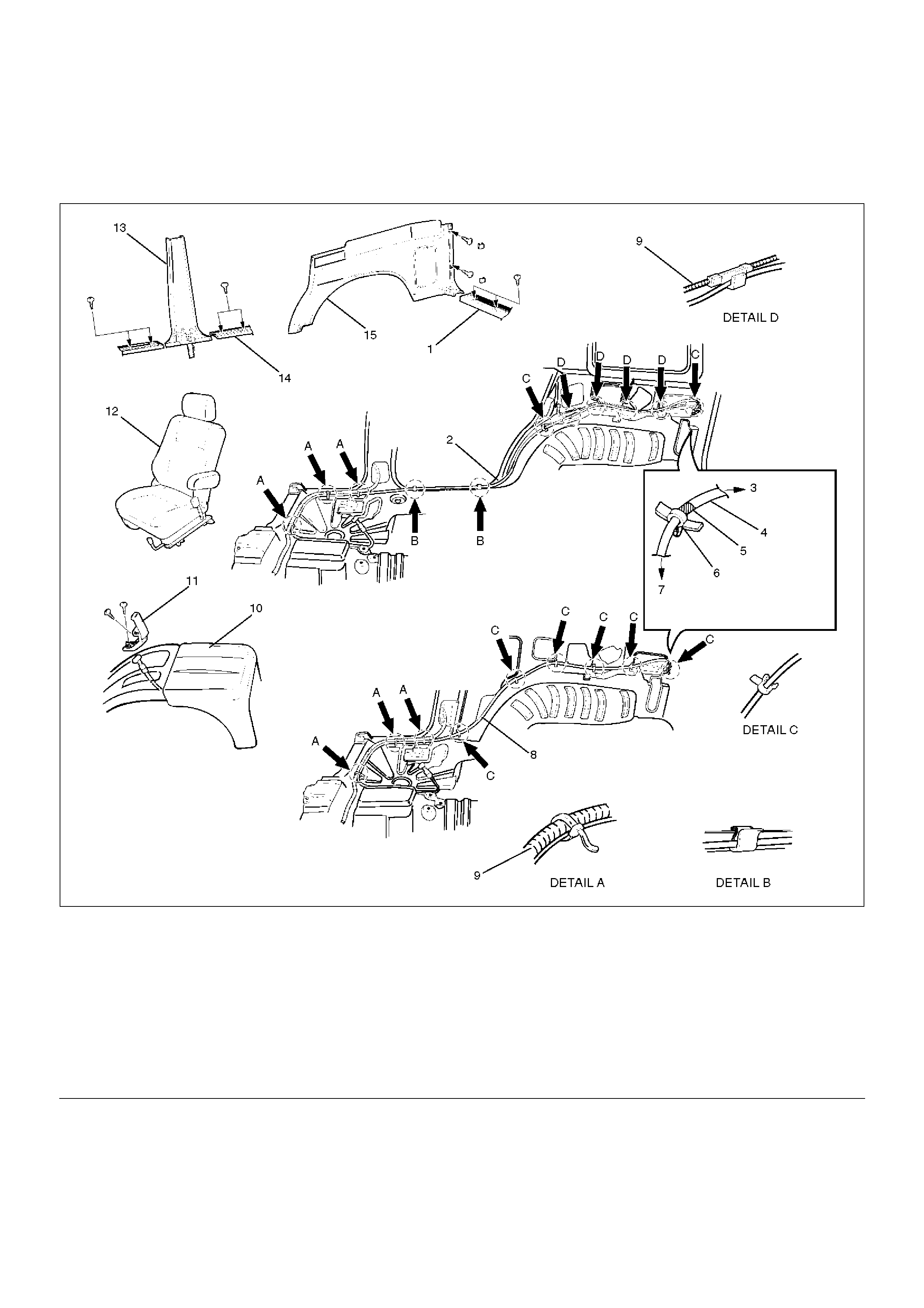
Fuel Filler Lid Opener Cable
Fuel Filler Lid Opener Cable and Associated Parts
686RW008
EndOFCallout
Removal
1.Disconnect the battery ground cable.
2.Remove the front seat (RH).
3.Remove the rear door sill plate (RH).
4.Remove the center pillar lower trim cover.
5.Remove the rear end floor trim panel.
6.Remove the luggage side trim panel (RH).
•Refer to the Luggage Side and Quarter Upper
Trim Cover in this section.
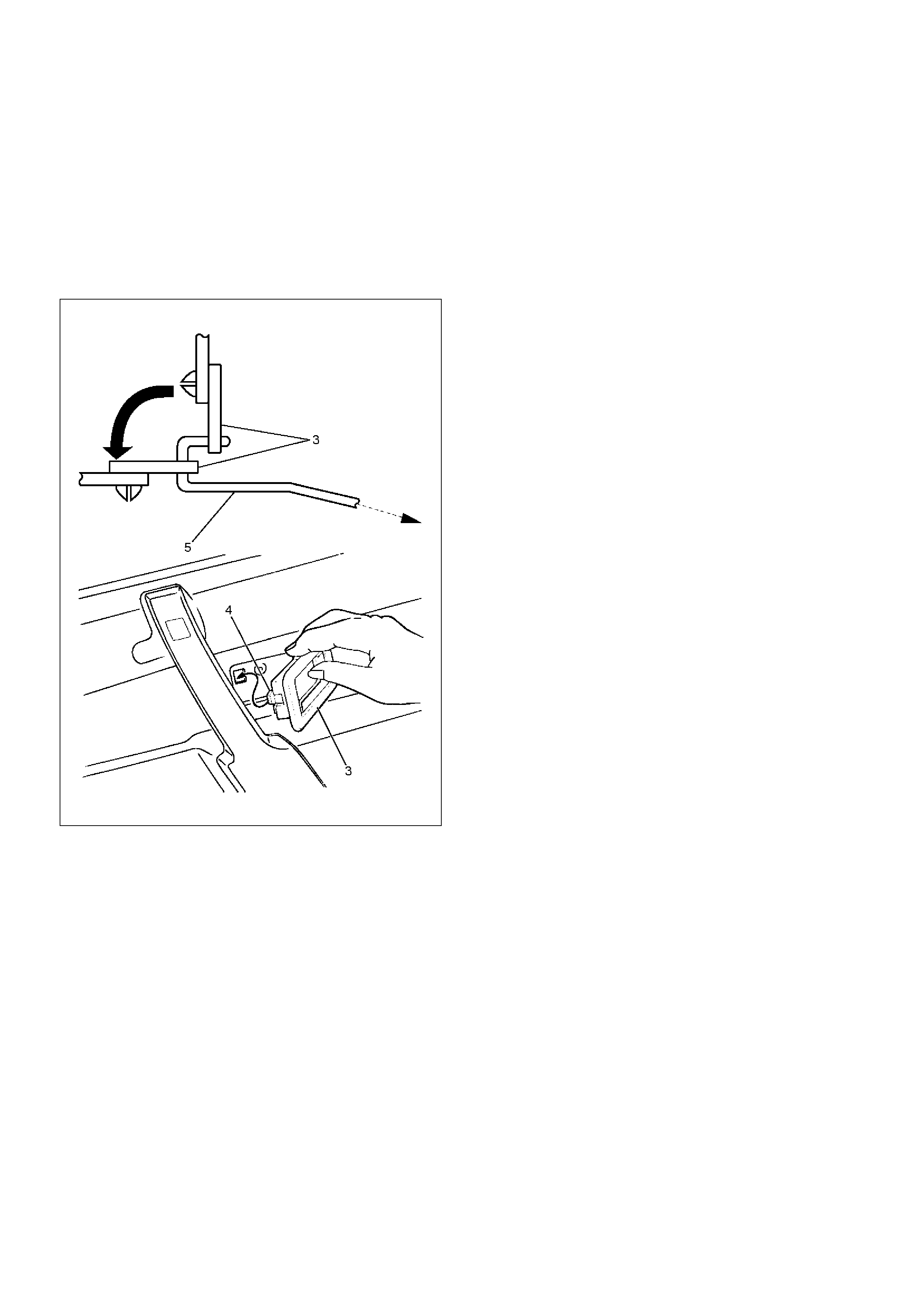
7. Remove the fuel filler lid opener(1).
Legend
(1) Rear End Floor Trim Cover
(2) Fuel Filler Lid Opener Cable (LWB)
(3) To Lever
(4) Cable
(5) Marking
(6) Clip
(7) To Door
(8) Fuel Filler Lid Opener Cable (SWB)
(9) Chassis Harness
(10) Center Console Assembly
(11) Fuel Filler Lid Opener
(12) Front Seat (RH)
(13) Center Pillar Lower Trim Cover
(14) Rear Door Sill Plate (RH)
(15) Luggage Side Trim Panel (RH)
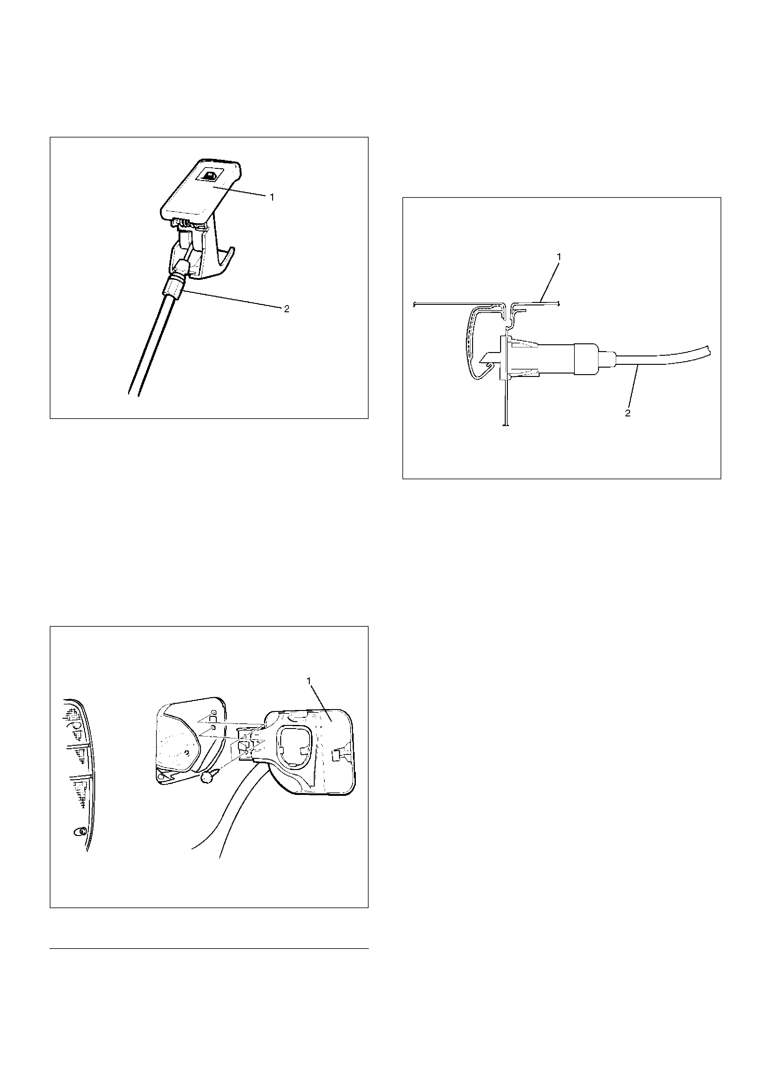
• Remove two opener fixing screws and disconnect
the cable(2).
686RW007
8. Remove the center console assembly.
9. Remove the fuel filler lid opener cable.
• Roll up the floor carpet and remove the clips of
the chassis harness and body panel to pull out
the cable toward the fuel filler lid.
Installation
To install, follow the removal steps in the reverse order,
noting the following points.
1. Insert the opener cable(2) into the body panel(1)
securely.
686RS002
2. Install the cable and clips to its original position to
the chassis harness and the body panel.
3. Check that the opener operates smoothly.
Fuel Filler Door
Parts Location
686RS003
EndOFCallout
Removal
1. Remove the fuel filler door.
Installation
1. Install the fuel filler door.
Legend
(1) Fuel Filler Door
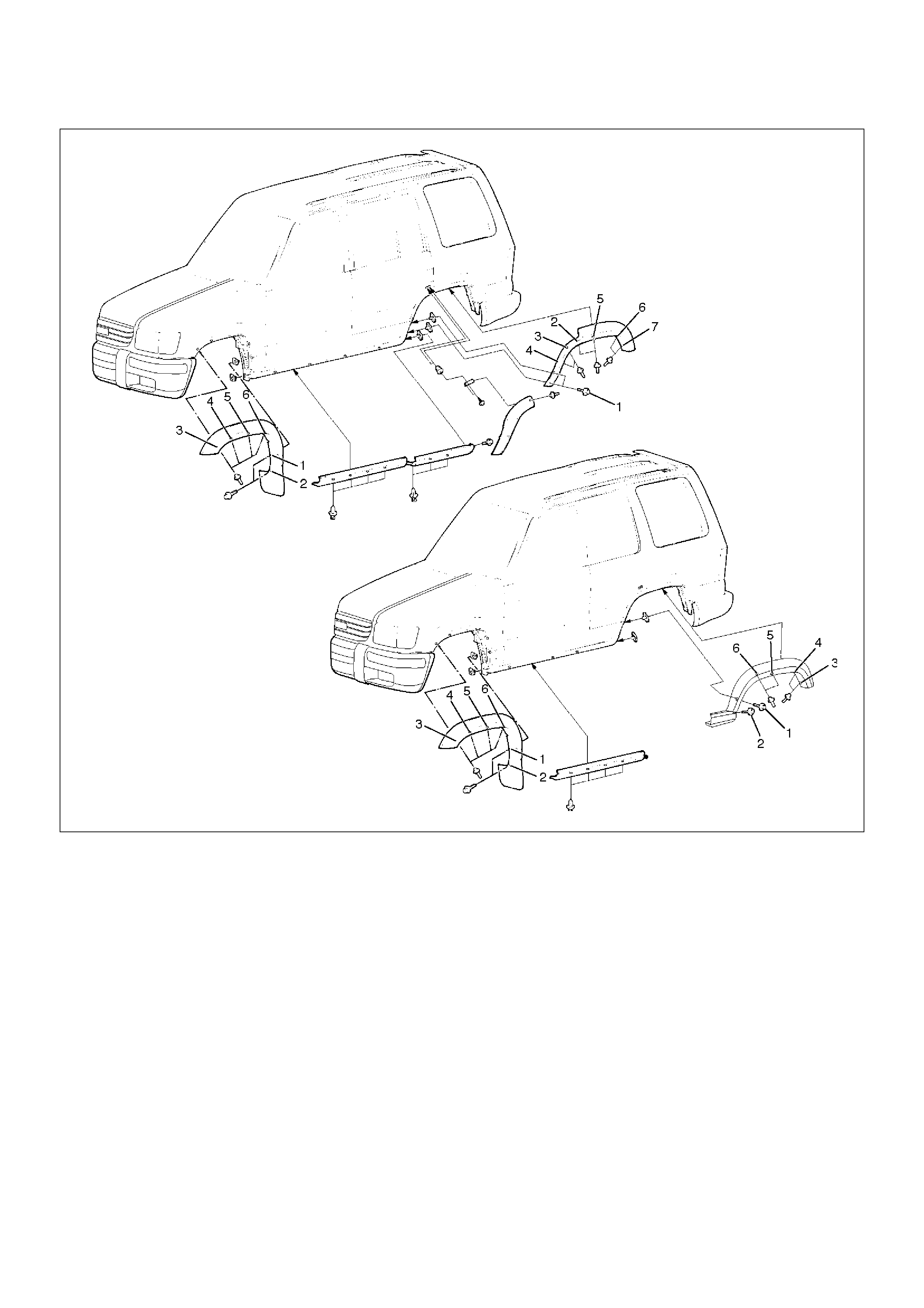
Rocker Protector (Without Wheel Opening Extension)
Rocker Protector (Without Wheel Opening Extension) and Associated Parts
603RW015
EndOFCallout
Removal
1. Remove the rear rocker protector.
2. Remove the front rocker protector.
Installation
To install, follow the remove steps in the reverse order.
Legend
(1) Rear Rocker Protector
(2) Inner Liner
(3) Spare Nut
(4) Fixing Screw
(5) Rocker Protector
(6) Outer Side Panel
(7) Outer Wheel House Panel
(8) Fixing Clip
(9) Outer Rocker Panel
(10) Door Panel
(11) Front Rocker Protector
(12) Clip (W/Rocker Protector)
(13) Fender Panel
(14) SWB
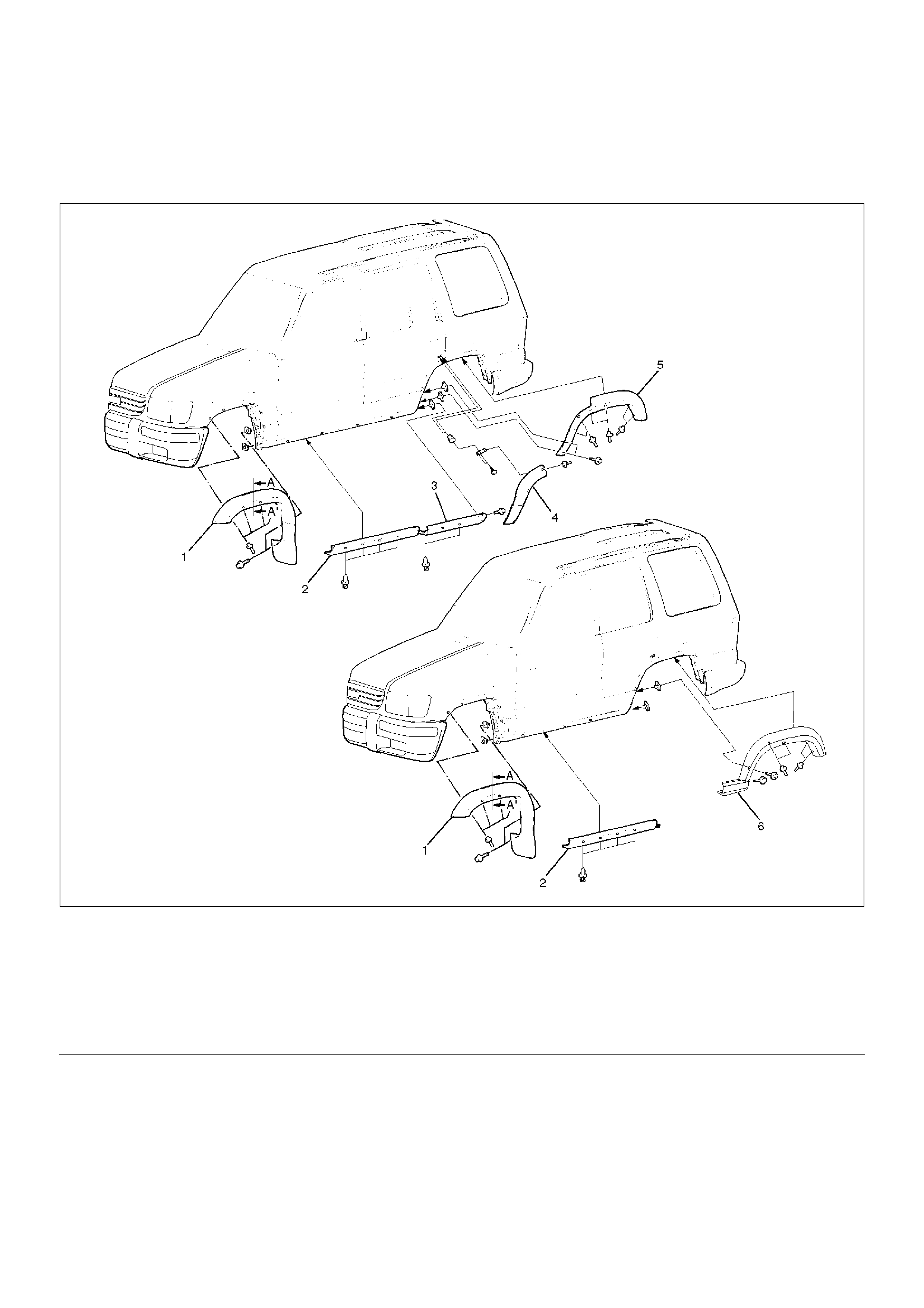
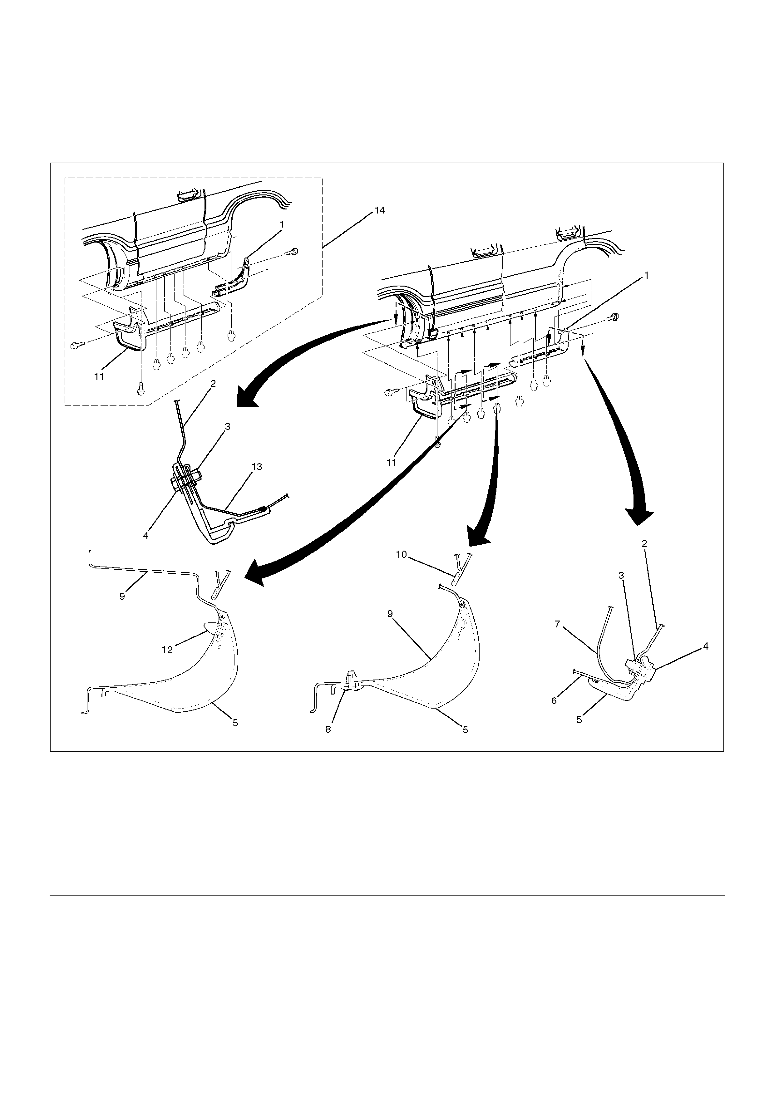
Wheel Opening Extension and Rocker Protector Assembly
Wheel Opening Extension, Rocker Protector Assembly and Associated Parts
620RW005
EndOFCallout
Removal
1. Remove the front wheel opening extension(2).
• Let a 5mm drill(3) go through four blind rivets(5)
to disengaged riveted portions.
Remove two screws and disengage five clips (6),
then remove the front wheel opening extension
assembly.
Legend
(1) Front Wheel Opening Extension Assembly
(2) Front Rocker Protector Assembly
(3) Rear Rocker Protector Assembly (Only LWB)
(4) Rear Door Wheel Opening Extension Assembly
(Only LWB)
(5) Rear Quarter Wheel Opening Extension
Assembly (Only LWB)
(6) Rear Wheel Opening Extension Assembly
(Only SWB)
620RS005
2. Remove the rear quarter wheel opening extension
assembly (Only LWB).
• Let a 5mm drill go through six blind rivets to
disengage riveted portions.
Disengage four clips, remove two screws, and
remove the rear quarter wheel opening extension
assembly.
3. Remove the rear wheel opening extension
assembly (Only SWB).
• Let a 5mm drill go through four blind rivets to
disengage riveted portions. Remove two screws,
disengage eight clips, and remove the rear wheel
opening extension assembly.
• Remove two fixing nuts (upper) and four fixing
bolts (lower).
4. Remove the rear door wheel opening extension
assembly (Only LWB).
• Let a 5mm drill go through a blind rivet to
disengage riveted portions.
Disengage three clips, peel off the bonded
portions with two double surface adhesive tape
and the rear door wheel opening extension
assembly.
5. Remove the rear rocker protector assembly (Only
LWB).
• Loosen and pull three clips, remove a rear screw,
and remove the rear rocker protector assembly.
6. Remove the front rocker protector assembly.
• Loosen and pull four clips, and remove the front
rocker protector assembly.
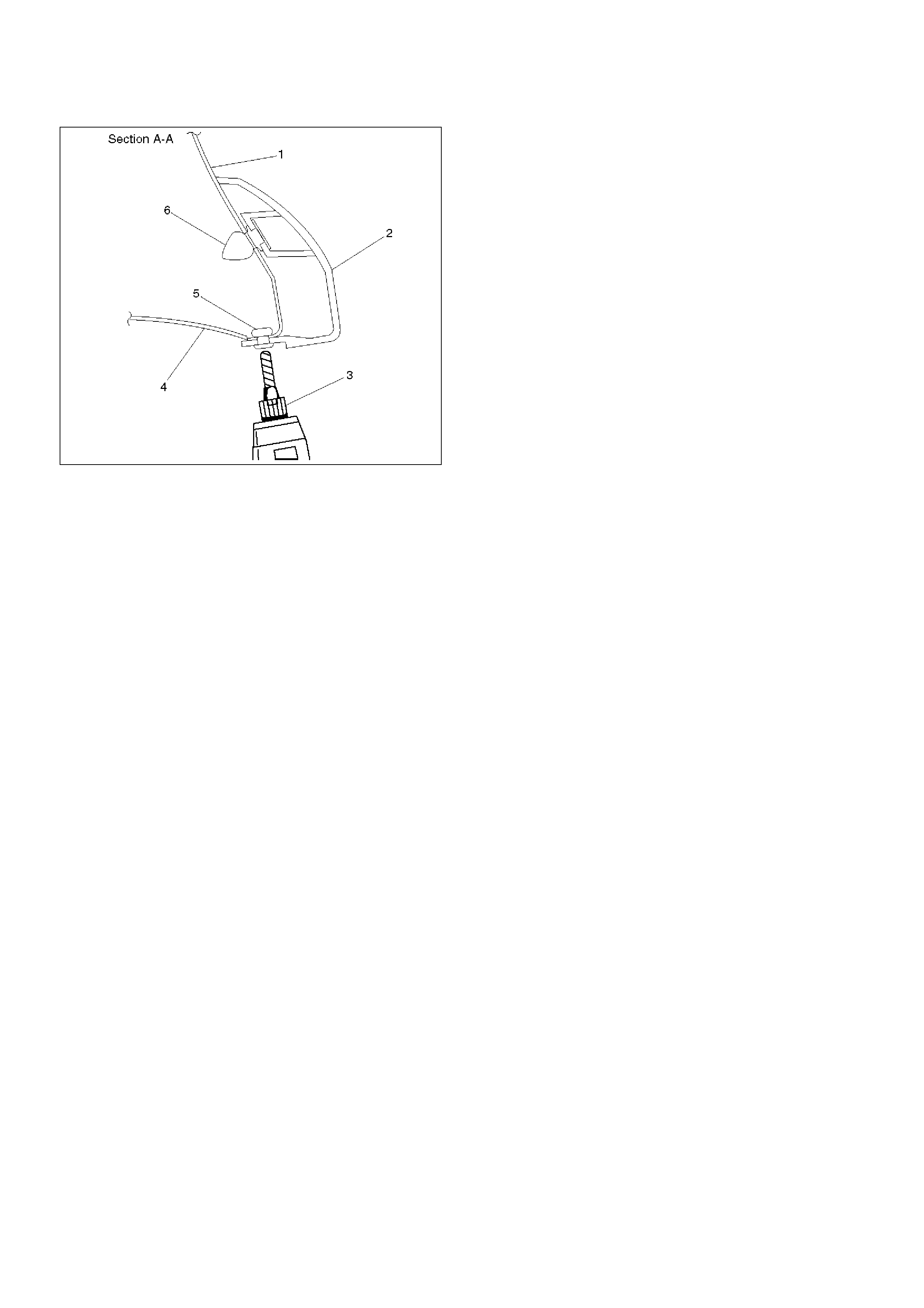
Installation
To install, follow the removal steps in the reverse order,
noting the following points.
1. Use a new 2–sided adhesive tape whenever
installing each wheel opening extension assembly
and rocker protector assembly. Using a white
gasoline, clean the places in advance where a 2–
sided adhesive tape is affixed. Also, install the clips,
screws and blind rivets in the order specified as
shown in the figure.
620RW006
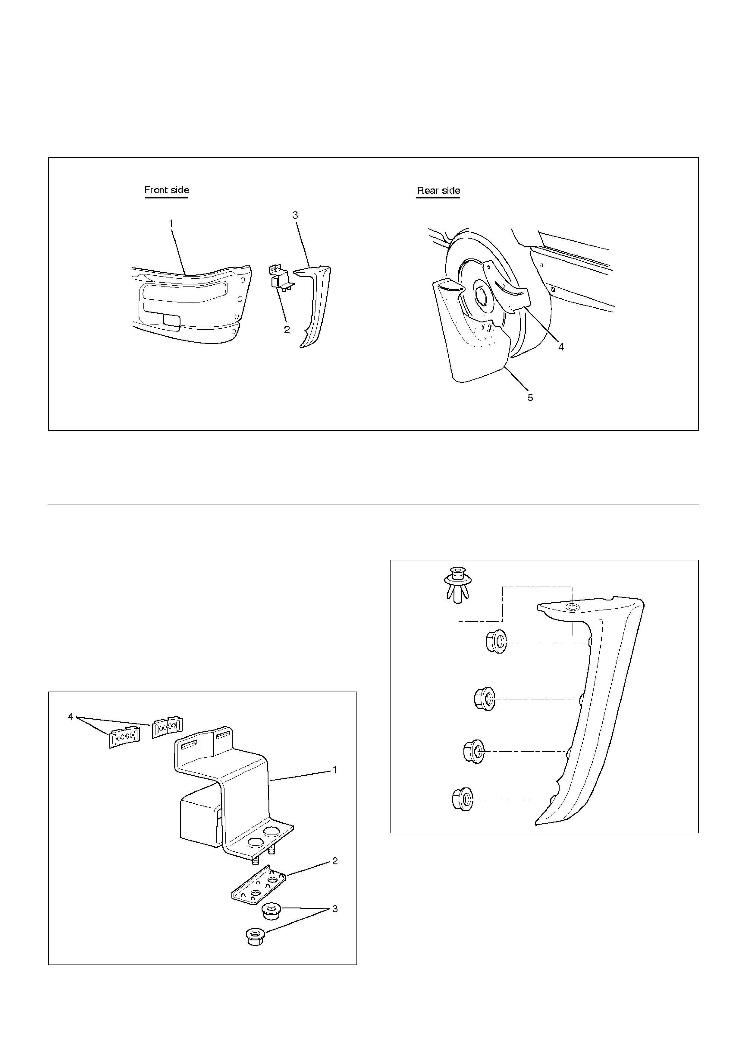
Mud Flaps (With Wheel Opening Extension)
Mud Flaps (With Wheel Opening Extension) and Associated Parts
620RW003
EndOFCallout
Removal
Front Side
1. Remove the front bumper assembly.
• Disconnect the front fog light connector and
remove two bolts from both sides of the front
bumper.
2. Remove the front bumper slider(1).
• Remove two clips(4) and two nuts(3), release the
claw from the washer(2).
601RW009
3. Remove the front mud flap.
• Remove four nuts and a clip.
601RW013
Rear Side
1. Remove the bumper side cover.
2. Remove the rear mud flap.
• Remove four bolts and two nuts.
Installation
To install, follow the removal steps in the reverse order.
Legend
(1) Front Bumper Assembly
(2) Front Bumper Slider
(3) Front Mud Flap
(4) Bumper Side Cover
(5) Rear Mud Flap
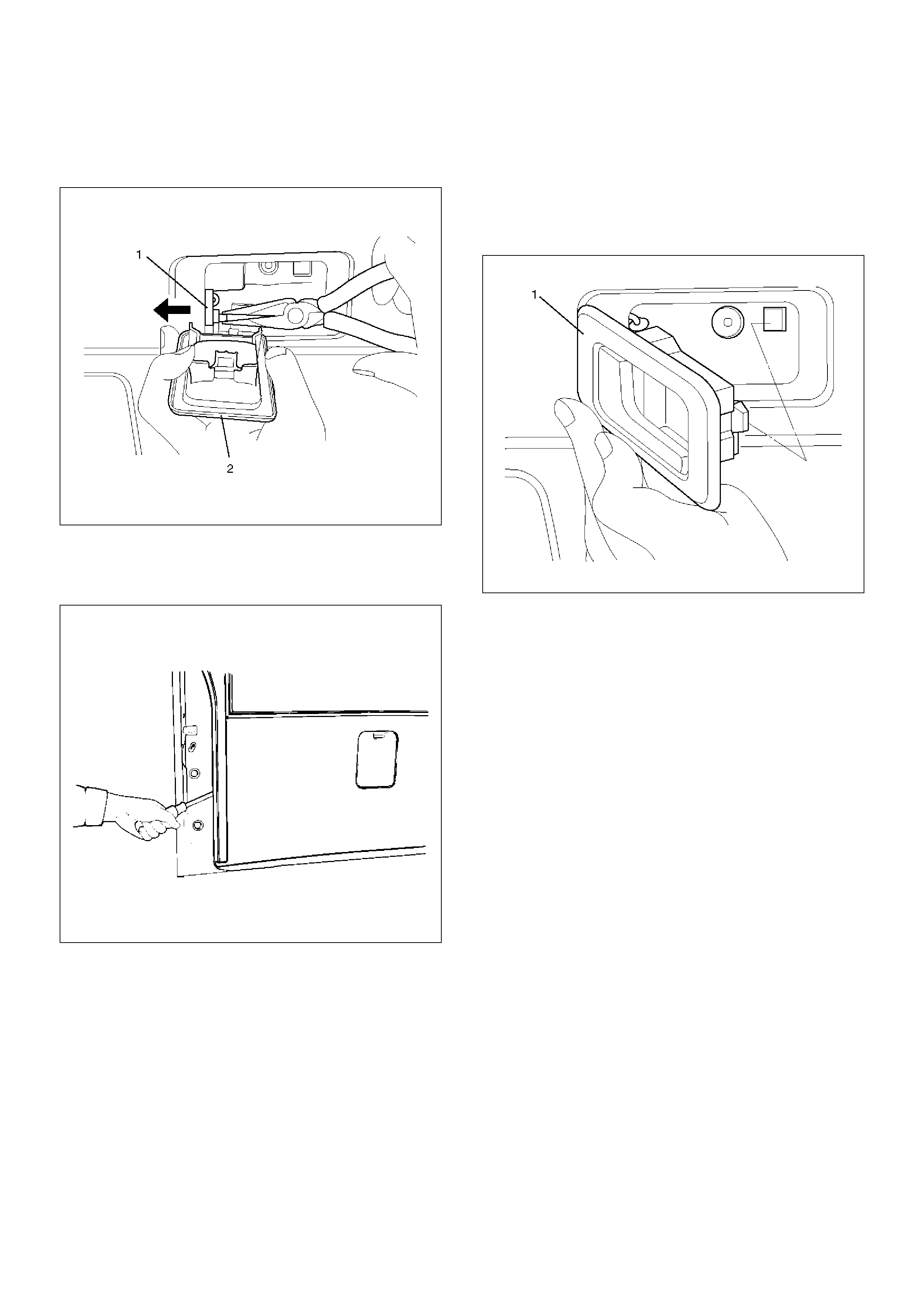
Ventilation Assembly
Ventilation Assembly and Associated Parts
641RS001
EndOFCallou
Removal
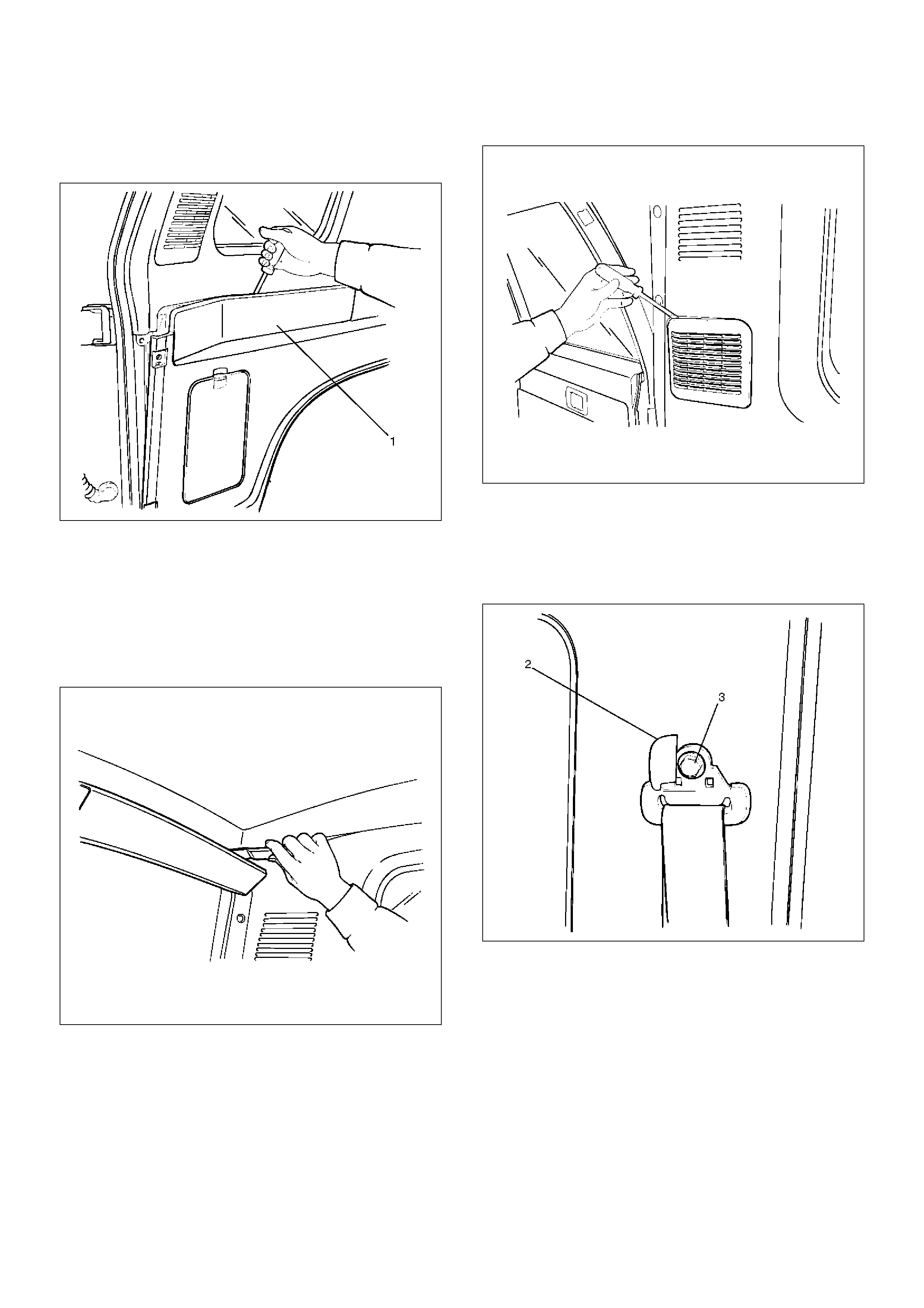
1. Remove the ventilation assembly(1).
• Pry the ventilation assembly retainers free from
the body panel.
641RS002
2. Remove the outlet valve assembly.
Installation
1. Install the outlet valve assembly.
• Insert the upper and lower catches of the outlet
valve into the body panel flange and fix them
securely.
2. Install the ventilation assembly.
• Fix the clips to the body panel securely so that
the ventilation assembly will not come off the
body panel.
Legend
(1) Outlet Valve Assembly
(2) Ventilation Assembly
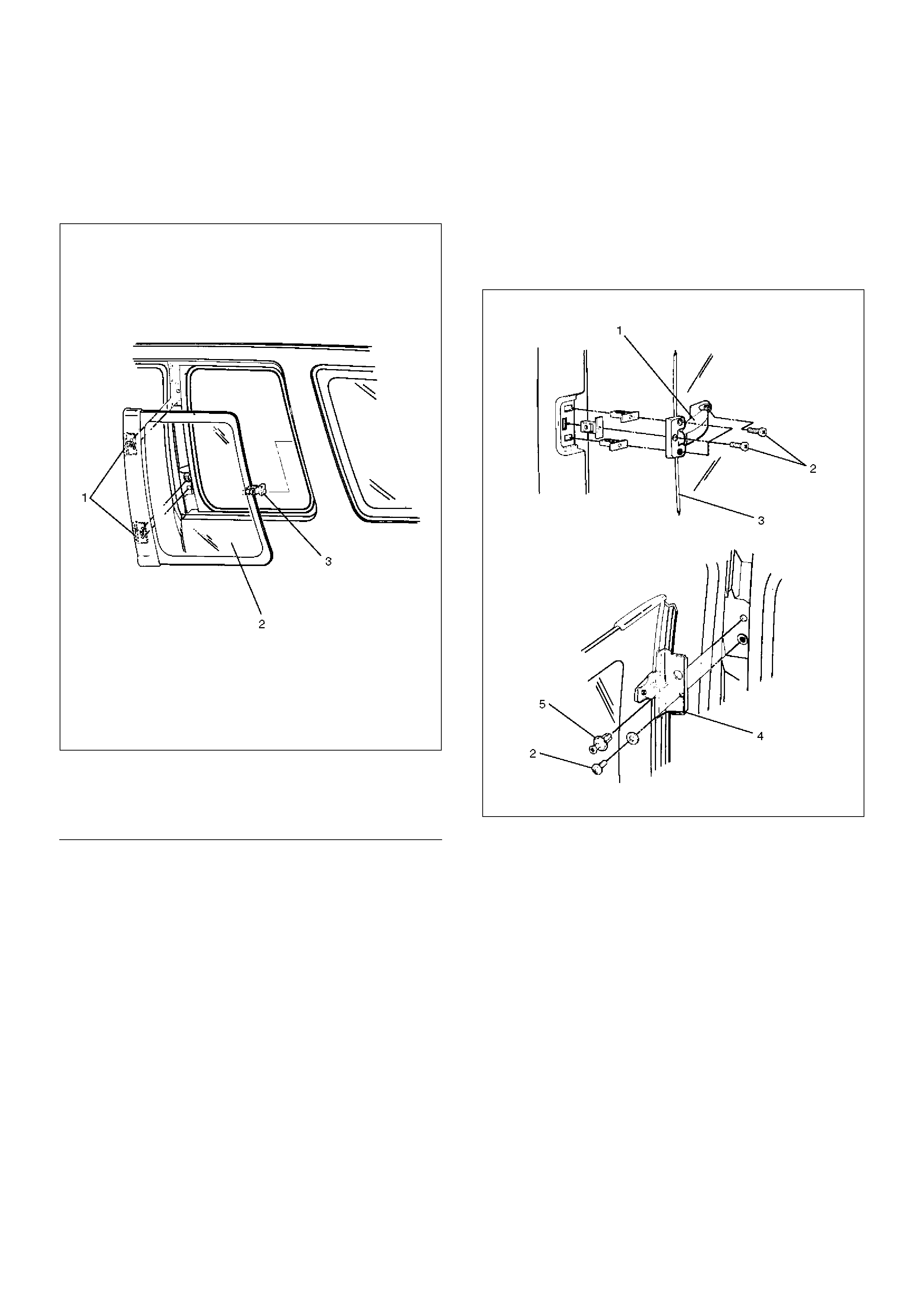
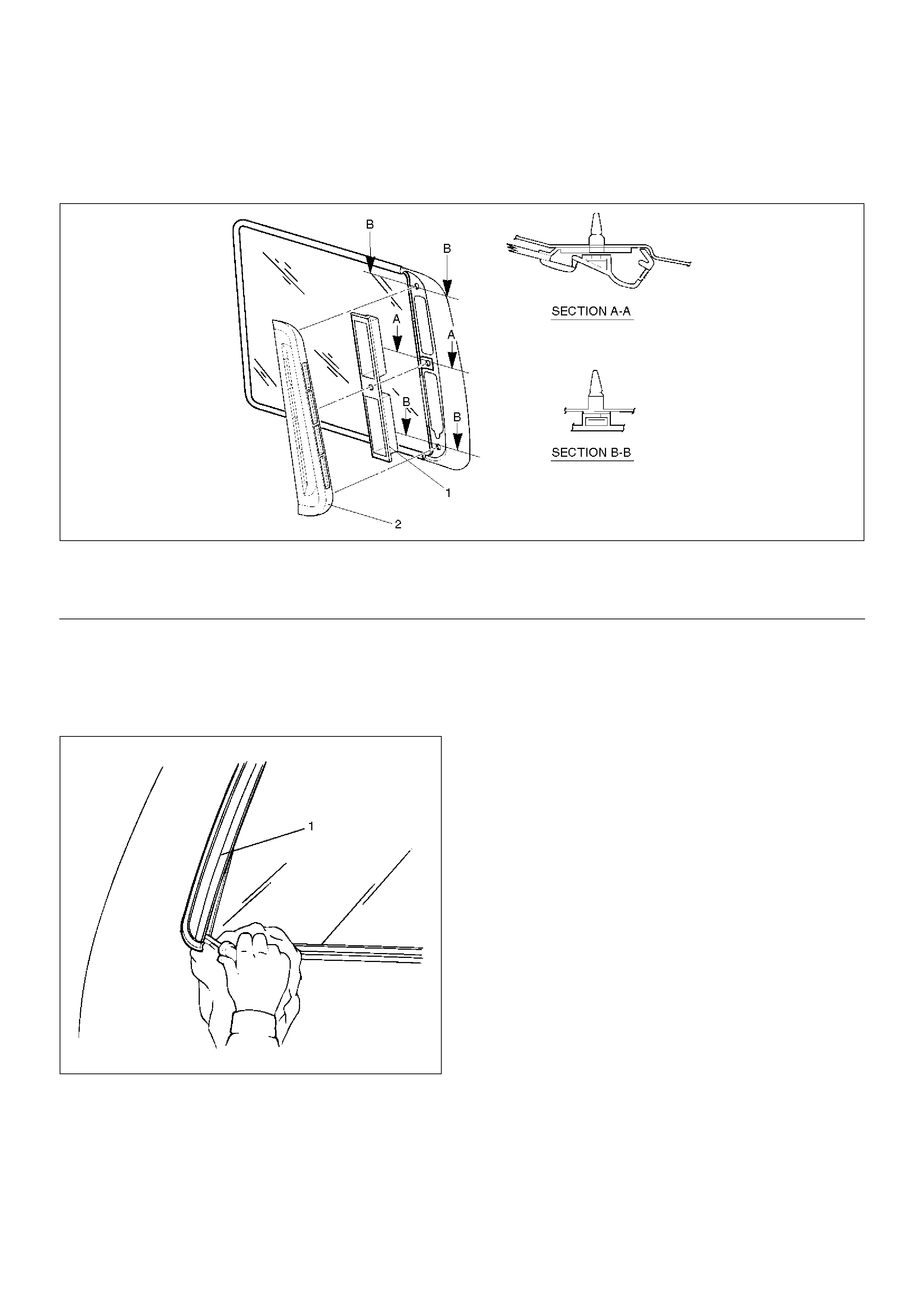
Quarter Flipper Glass Assembly (SWB)
Quarter Flipper Glass Assembly and
Associated Parts
641RW003
EndOFCallout
Removal
1. Remove the quarter flipper glass assembly (3).
• Remove the fixing screws (2) and rivet (5).
2. Remove the fastener (1).
3. Remove the hinge assembly (4).
641RW002
Installation
To install, follow the removal steps in the reverse order.
Legend
(1) Hinge Assembly
(2) Quarter Flipper Glass Assembly
(3) Fastener
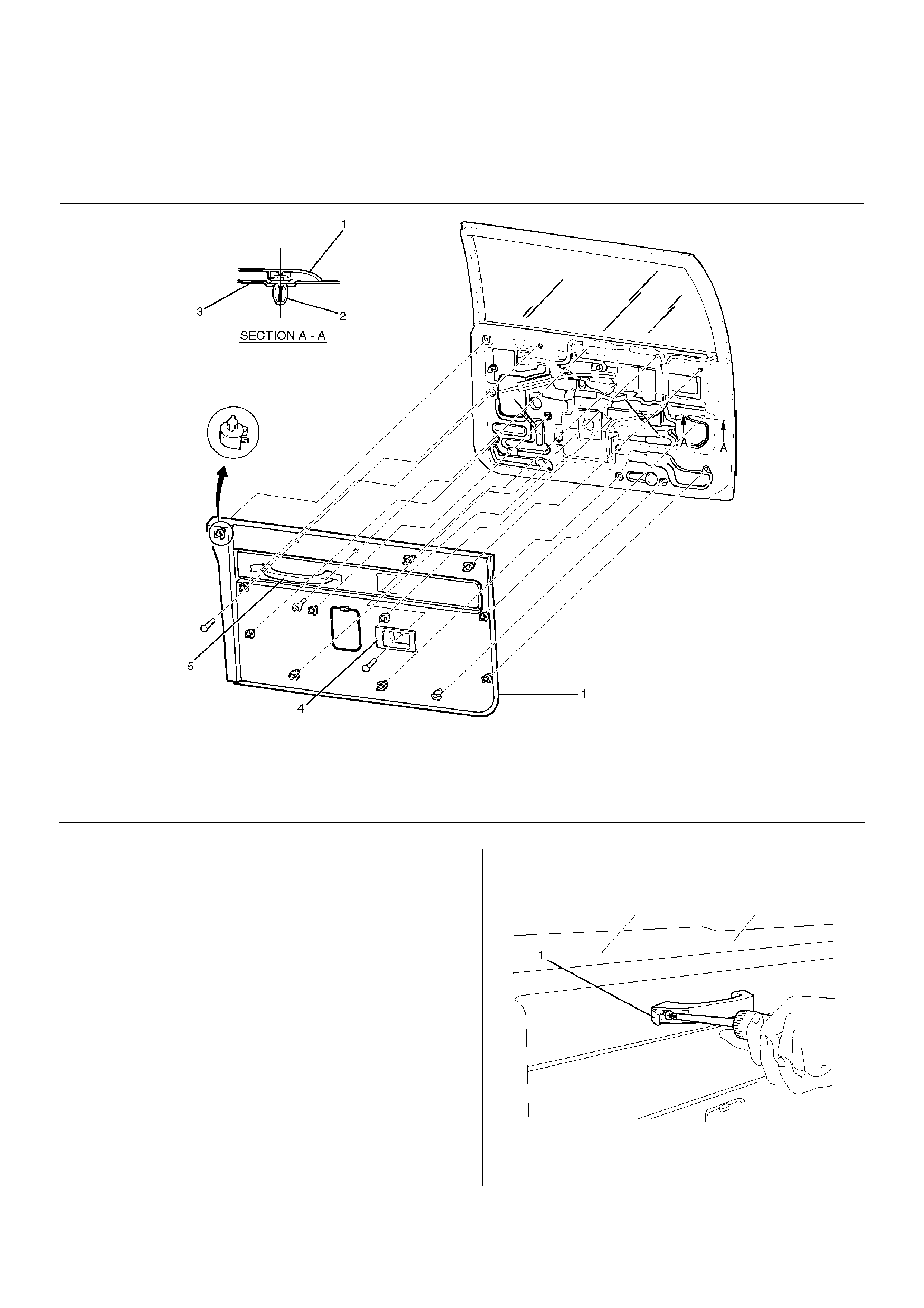
Tailgate Trim Panel (LH)
Tailgate Trim Panel (LH) and Associated Parts
683RW017
EndOFCallout
Removal
1. Disconnect the battery ground cable.
2. Remove the tailgate assist grip.
• Open the assist covers (1) and remove two fixing
screws.
683RW019
Legend
(1) Tailgate Trim Panel (LH)
(2) Clip
(3) Tailgate Panel
(4) Inside Handle
(5) Tailgate Assist Grip
3. Remove the inside handle (2).
• Remove the fixing screw and disconnect the
locking link (1).
683RW020
4. Remove the tailgate trim panel (LH).
• Pry the trim panel retainers free from the tailgate
panel.
684RS001
Installation
To install, follow the removal steps in the reverse order,
noting the following point.
1. Install the inside handle (1), connect the link to the
handle, insert the catch portion of the handle into
the tailgate side hole securely and fix it with a screw.
683RW018
Tailgate Trim Panel (RH)
Parts Location
684RS002
EndOFCallout
Removal
1. Disconnect the battery ground cable.
2. Remove the tailgate trim panel (RH).
• Pry trim panel retainer free from the tailgate
panel.
684RS003
Installation
To install, follow the removal steps in the reverse order,
noting the following points.
1. Insert the retainer of the trim panel into the tailgate
panel and fix it securely.
Legend
(1) Tailgate Trim Panel
Luggage Floor Box
Luggage Floor Box and Associated Parts
643RS006
EndOFCallout
Remove
1. Fold the rear seat assembly to the front direction.
2. Remove the luggage floor box cover.
• Remove the clips which connect the floor carpet
and the luggage floor box cover.
3. Remove the luggage floor box.
Installation
To install, follow the removal steps in the reverse order.
Rope Hook Set
Rope Hook Set and Associated Parts
676RS003
EndOFCallout
Removal
1. Remove the rope hook set.
• Open the hook cover and hook fixing bolt.
Installation
1. Install the rope hook set.
• Tighten the hook fixing bolt to the specified
torque.
Torque: 13N·m (1.3kg·m/113lbin)
Legend
(1) Rear Seat
(2) Floor Carpet
(3) Luggage Floor Box
(4) Luggage Floor Box Cover
Legend
(1) Rope Hook Set
(2) Cover
(3) Luggage Floor Carpet
(4) Hook
Power Door Mirror System
General Description
The circuit consists of the starter switch, door mirror
control switch, folding switch, defogger switch and door
mirrors on both sides.
The door mirror switch consists of the control switch,
folding switch and defogger switch.
When the control switch is operated with the starter
switch at either “ACC” or “ON” position, the motors
incorporated in the door mirrors on both sides rotates to
allow the horizontal and vertical adjustment of mirror
angles.
The folding switch can be used to fold the mirror and
return it to its original position.
When turning on the door mirror defogger switch with
the starter switch at “ON” position, built-in heater in the
mirror is activated to perform the defogger function.
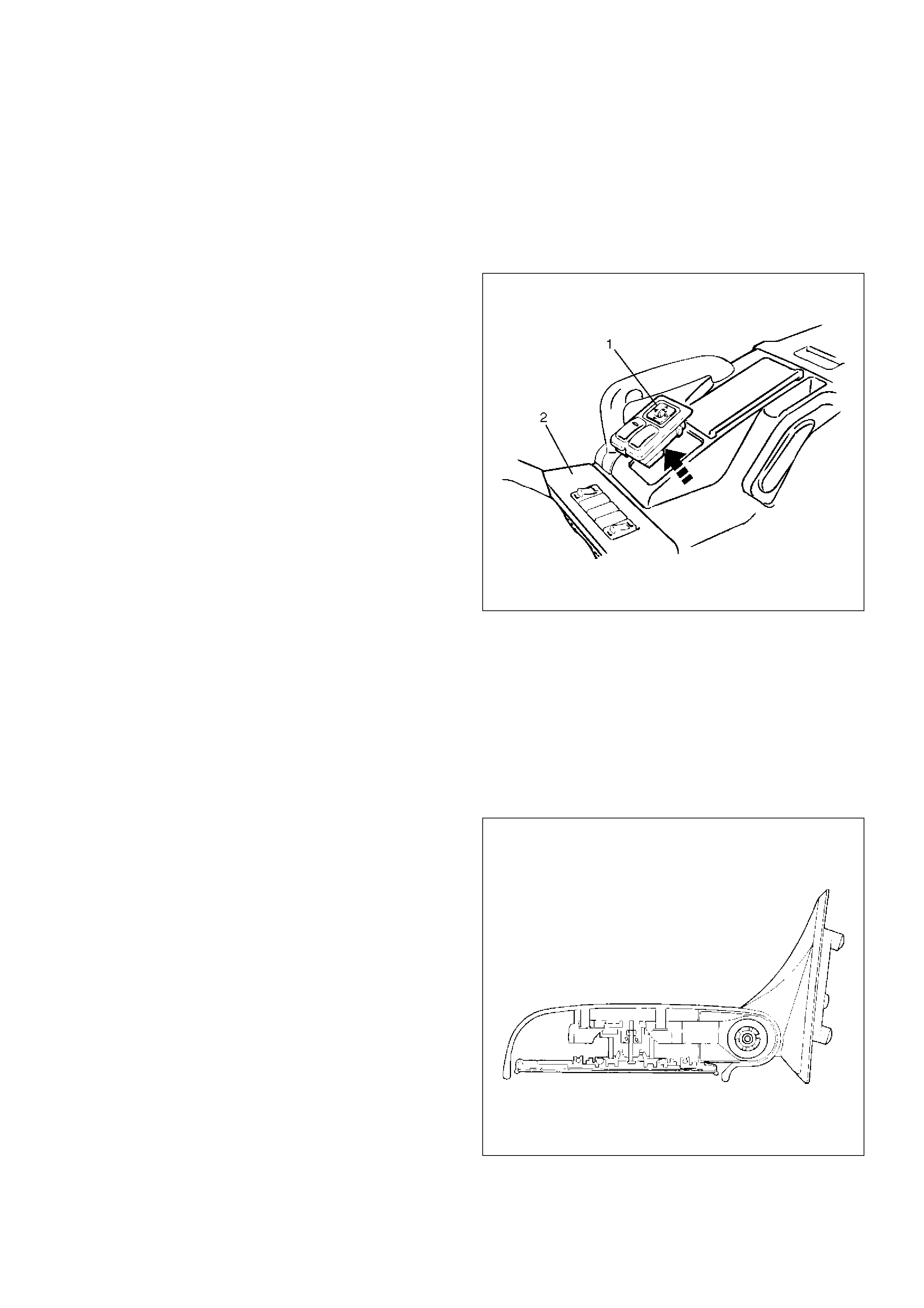
Door Mirror Switch Assembly (Control
Switch, Folding Switch and Defogger
Switch) Removal
1.Disconnect the battery ground cable.
2.Remove the front console assembly(2).
•Remove four screws.
•Remove the transmission shift lever knob.
•Remove the transfer shift lever knob.
•Disconnect the seat heater switch connectors (if
so equipped).
•Disconnect the door mirror switch connectors.
•Disconnect the power & winter switch
connectors. (A/T only)
3.Remove the door mirror switch assembly(1).
•Push the lock from the back side of the front
console.
825RS005
Installation
To install, follow the removal steps in the reverse order,
noting the following point.
1.Depress the switch with your fingers until it locks
securely.
Power Door Mirror
General Description
Mirrors contain two driving motors for the horizontal and
vertical movement of the mirror and one motor for
folding the mirror.
The movement of the mirror is controlled by the
direction of current running through these motors.
The housing portion of the mirror is provided with the
auto-stop mechanism which is interlocked with the
motor for folding the mirror. When the mirror moves to
the stop position (with the mirror folded or returned to its
original position), the current to the motor is shut off.
When the mirror cannot operate due to some obstacle
and the motor stops its rotation, the resistor prevents
current overflow.
720RS004
Removal and Installation
Refer to the Door Mirror removal and installation steps
in this section.
Power Window System
General Description
The circuit consists of the starter switch, (door lock &)
power window switch for each of the front windows,
power window switch for rear windows and power
window motors.
When the starter switch is turned on, the battery voltage
is applied to each of the power window switches
through the circuit breaker and the power window relay
on the circuit.
The “Down” switch of the driver's power window switch
has a built-in function which can be operated by just
touching it.
Accordingly, the window will roll down automatically by
just setting the switch to the “AUTO” position.
When the driver's power lock switch at the driver side is
depressed, the power source to the passenger's power
window switches are shut off. So, even if these
switches are operated, the power window motor will not
operate.
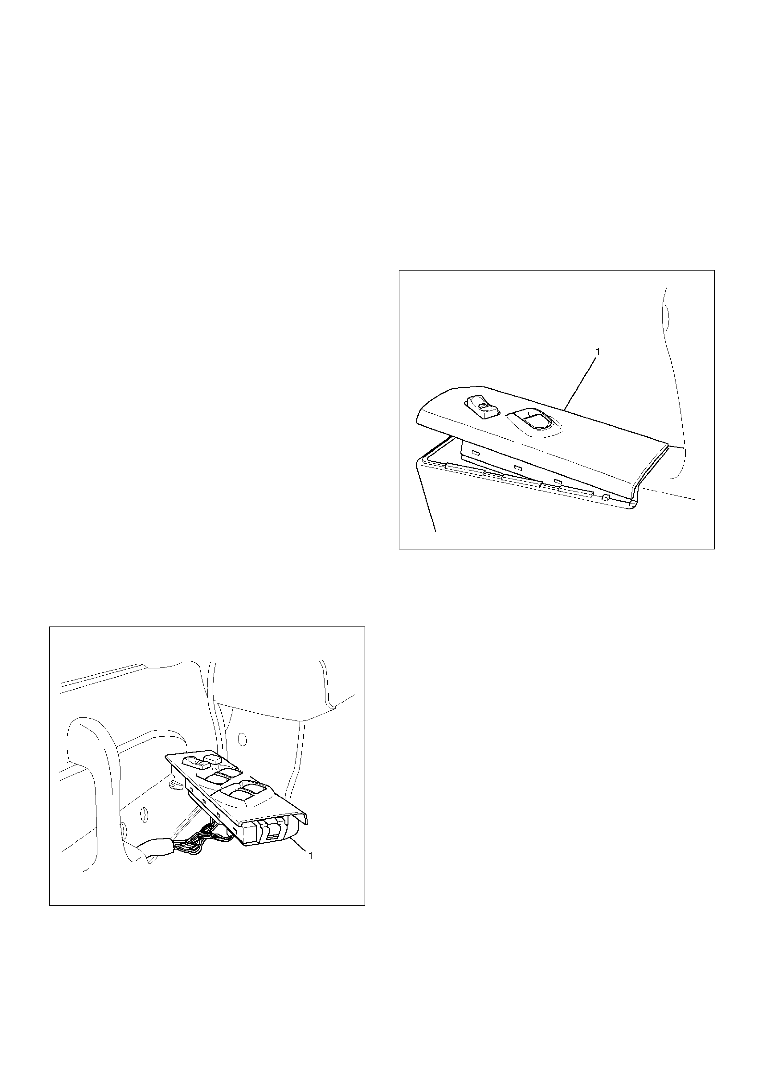
Power Window Switch Removal and
Installation
Driver Seat Side
Removal
1. Disconnect the battery ground cable.
2. Remove the switch(1).
• Pull out the switch by pushing the spring with the
tip of a screwdriver.
• Disconnect two connectors.
825RS052
Installation
To install, follow the removal steps in the reverse order.
Front Passenger Seat Side
Removal
1. Disconnect the battery ground cable.
2. Remove the switch(1).
• Pull out the switch by pushing the spring with the
tip of a screwdriver.
• Disconnect the connector.
825RW046
Installation
To install, follow the removal steps in the reverse order.
Rear-Left and Right Sides
Removal
1. Disconnect the battery ground cable.
2. Remove the switch(1).
• Pull out the switch by pushing the spring with the
tip of a screwdriver.
• Disconnect the connector.
825RS057
Installation
To install, follow the removal steps in the reverse order.
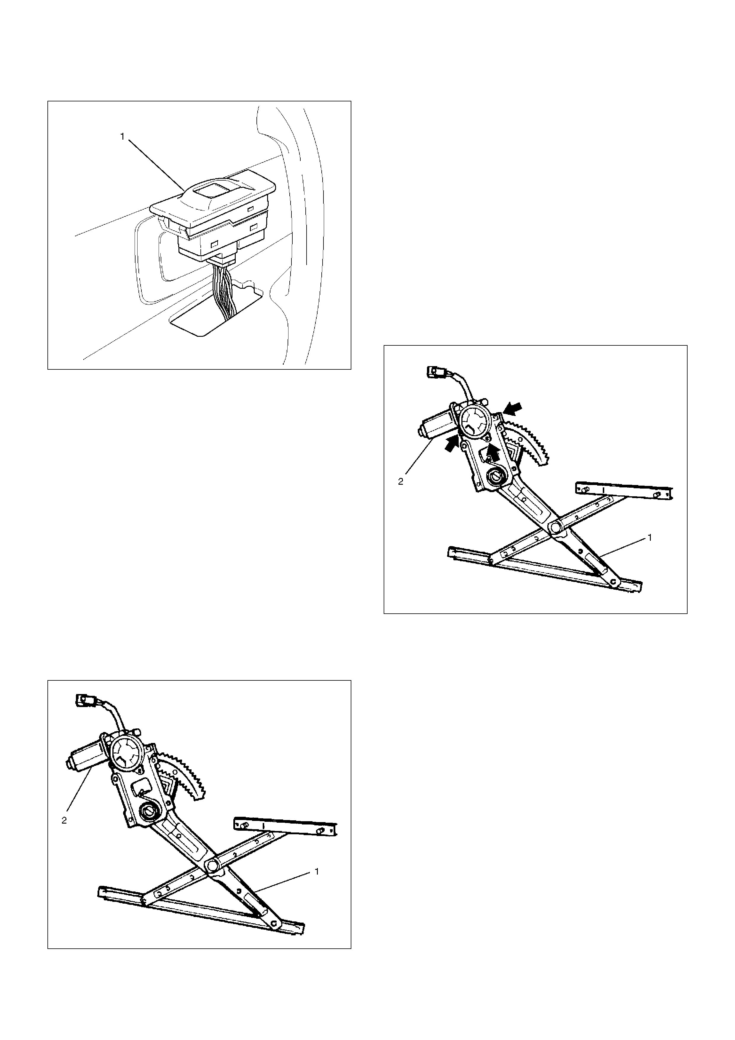
Power Window Motor Removal and
Installation
Driver Seat Side
Removal
1.Disconnect the battery ground cable.
2.Remove the window regulator assembly (1).
•Refer to the Front Window Regulator, Glass And
Glass Run in Body Structure section.
3.Remove the power window motor(2).
•Remove three screws.
CAUTION: When removing the motor from the
regulator(1), be careful not to get injured by the
strong repellent force of the regulator spring.
631RS018
Installation
To install, follow the removal steps in the reverse order.
Front Passenger Seat Side
Removal
1.Disconnect the battery ground cable.
2.Remove the window regulator assembly (1).
•Refer to the Front Window Regulator, Glass And
Glass Run in Body Structure section.
3.Remove the power window motor(2).
•Remove three screws.
CAUTION: When removing the motor from the
regulator(1), be careful not to get injured by the
strong repellent force of the regulator spring.
631RS015
Installation
To install, follow the removal steps in the reverse order.
Rear-Left Side
Removal
1.Disconnect the battery ground cable.
2.Remove the rear window regulator assembly.
•Refer to the Rear Window Regulator And Glass
in Body Structure section.
3. Remove the power window motor(1).
• Remove four screws.
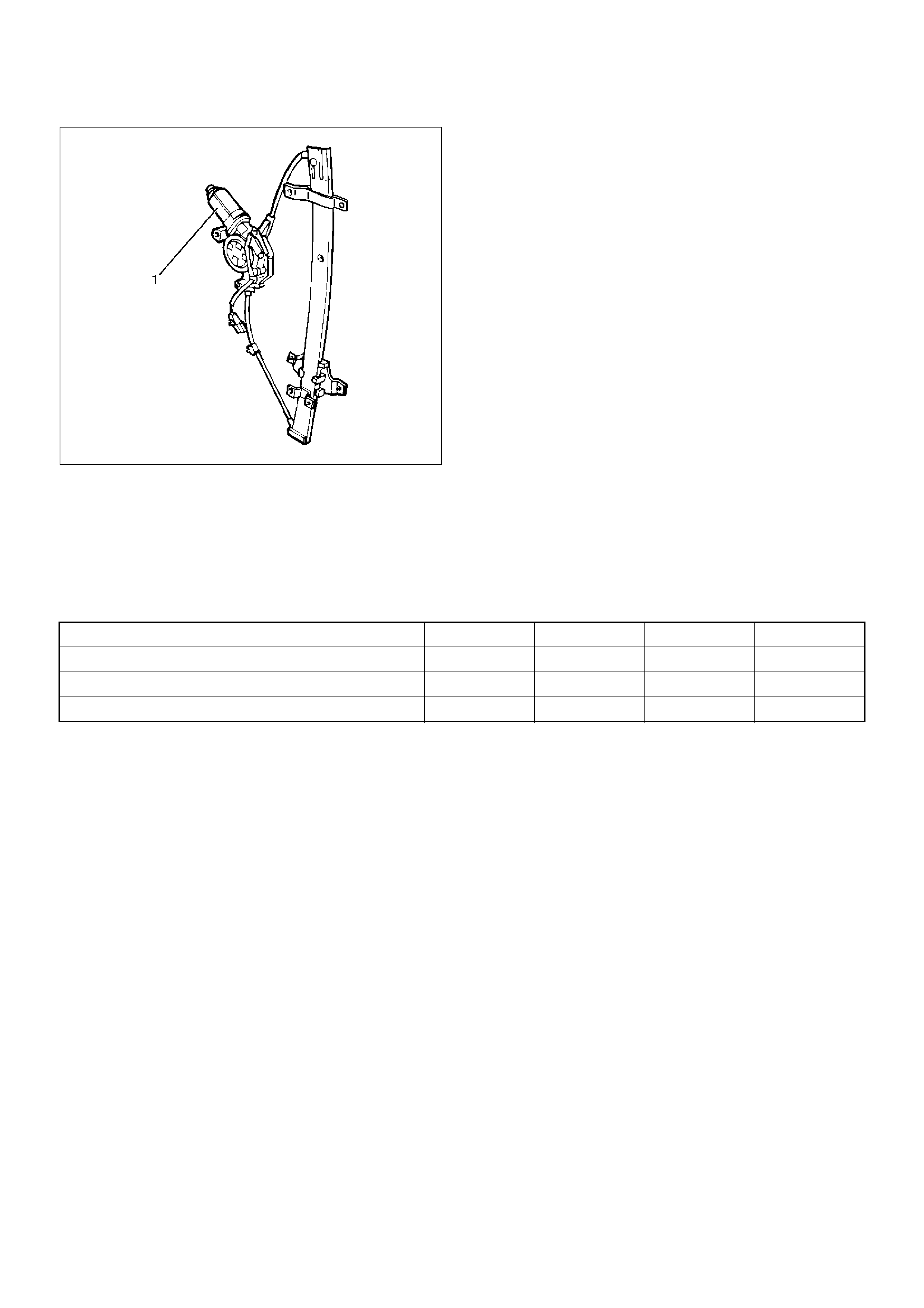
651RW014
Installation
To install, follow the removal steps in the reverse order.
Rear-Right Side
Removal and Installation
Refer to the Rear Power Window Motor-Left Side in this
section.
Main Data and Specifications
Torque Specifications
Application N·m kg·m lbft lbin
Door Mirror Fixing Bolts 8 0.8 — 69
Seat Belt Anchor Bolts 39 4.0 29 —
Hook Fixing Bolt 13 1.3 — 113