
SECTION 1D - DOOR LOCKS
Service Precaution
Front Door Lock Assembly
Front Door Lock Assembly and Associated Parts
Removal
Installation
Front Outside Handle and Door Lock Cylinder
Front Outside Handle, Door Lock Cylinder and
Associated Parts
Removal
Installation
Rear Door Lock Assembly
Rear Door Lock Assembly and Associated Parts
Removal
Installation
Rear Outside Handle
Rear Outside Handle and Associated Parts
Removal
Installation
Rear Door Inside Lock Knob Link
Removal
Installation
Door Inside Lock Knob
Removal
Installation
Door Inside Handle
Removal and Installation
Tailgate Lock Assembly (LH)
Tailgate Lock Assembly (LH) and Associated Parts
Removal
Installation
Tailgate Lock Assembly (RH)
Tailgate Lock Assembly (RH) and Associated Parts
Removal
Installation
Tailgate Inside Lock Knob
Removal
Installation
Tailgate Inside Handle
Parts Location
Removal and Installation
Tailgate Outside Handle and/or Tailgate Lock Cylinder
Tailgate Outside Handle and/or Tailgate Lock
Cylinder and Associated Parts
Removal
Installation
Key
Key Coding
Key Styles
Power Door Lock System
General Description
Front Door Lock Actuator Removal
Front Door Lock Actuator Installation
Rear Door Lock Actuator Removal
Rear Door Lock Actuator Installation
Tailgate Lock Actuator Removal
Tailgate Lock Actuator Installation
Main Data and Specifications
Torque Specifications

Service Precaution
WARNING: IF SO EQUIPPED WITH A
SUPPLEMENTAL RESTRAINT SYSTEM (SRS),
REFER TO THE SRS COMPONENT AND WIRING
LOCATION VIEW IN ORDER TO DETERMINE
WHETHER YOU ARE PERFORMING SERVICE ON
OR NEAR THE SRS COMPONENTS OR THE SRS
WIRING. WHEN YOU ARE PERFORMING SERVICE
ON OR NEAR THE SRS COMPONENTS OR THE
SRS WIRING, REFER TO THE SRS SERVICE
INFORMATION. FAILURE TO FOLLOW WARNINGS
COULD RESULT IN POSSIBLE AIR BAG
DEPLOYMENT, PERSONAL INJURY, OR
OTHERWISE UNNEEDED SRS SYSTEM REPAIRS.
CAUTION: Always use the correct fastener in the
proper location. When you replace a fastener, use
ONLY the exact part number for that application.
HOLDEN will call out those fasteners that require a
replacement after removal. HOLDEN will also call
out the fasteners that require thread lockers or
thread sealant. UNLESS OTHERWISE SPECIFIED,
do not use supplemental coatings (Paints, greases,
or other corrosion inhibitors) on threaded fasteners
or fastener joint interfaces. Generally, such
coatings adversely affect the fastener torque and
the joint clamping force, and may damage the
fastener. When you install fasteners, use the correct
tightening sequence and specifications. Following
these instructions can help you avoid damage to
parts and systems.
Front Door Lock Assembly
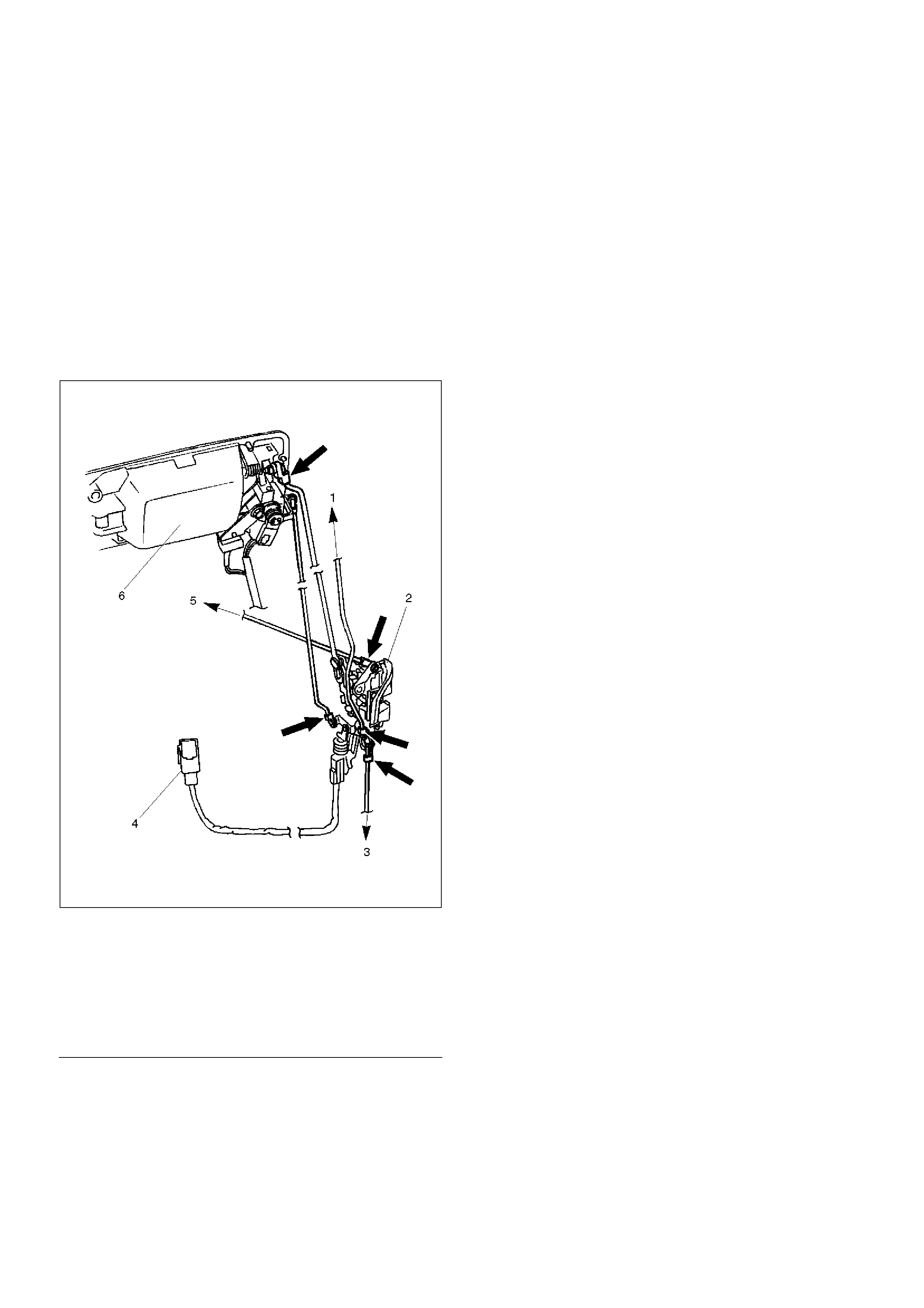
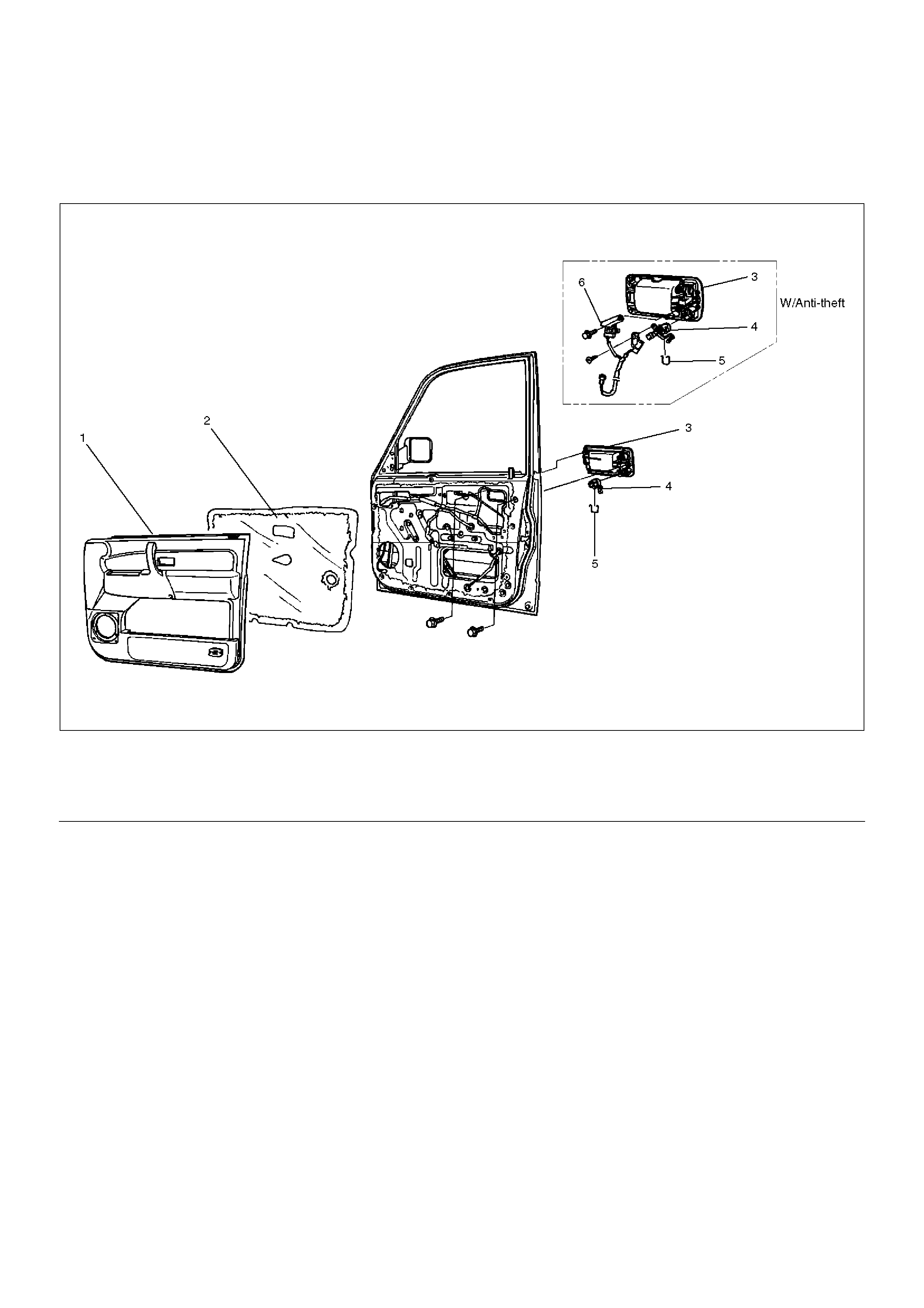
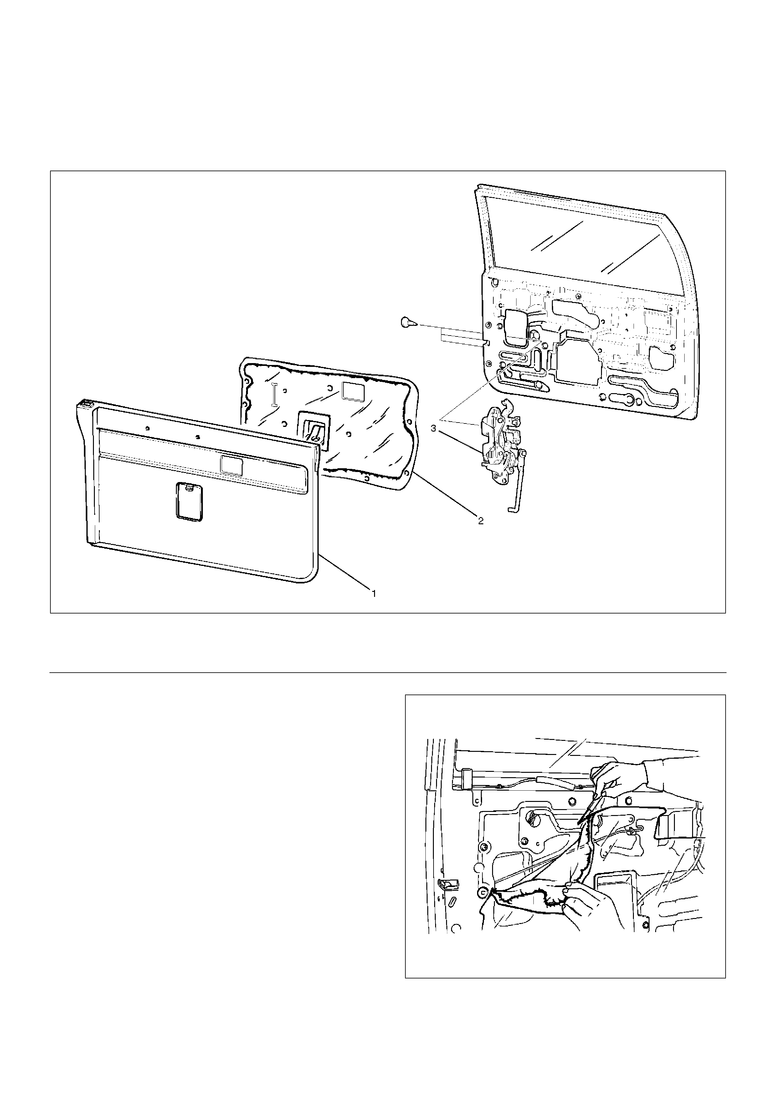
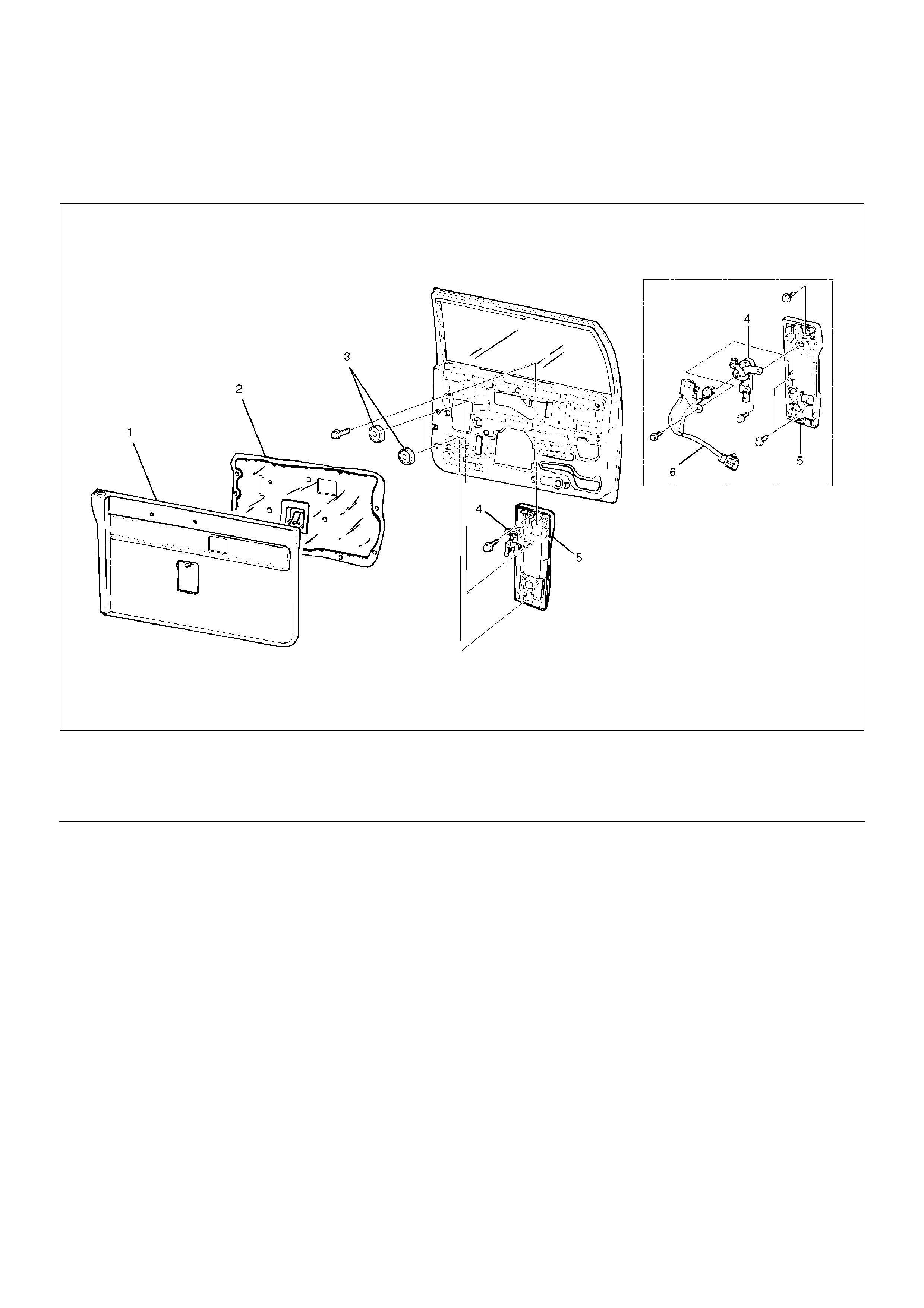
Front Door Lock Assembly and Associated Parts
632RS003
EndOFCallout
Legend
(1) Door Trim Panel
(2) Waterproof Sheet
(3) To Outside Handle
(4) Rear Guide Rail
(5) Door Lock Assembly
(6) Door Lock Switch Connector (W/Power Door
Lock)
Removal
1. Disconnect the battery ground cable.
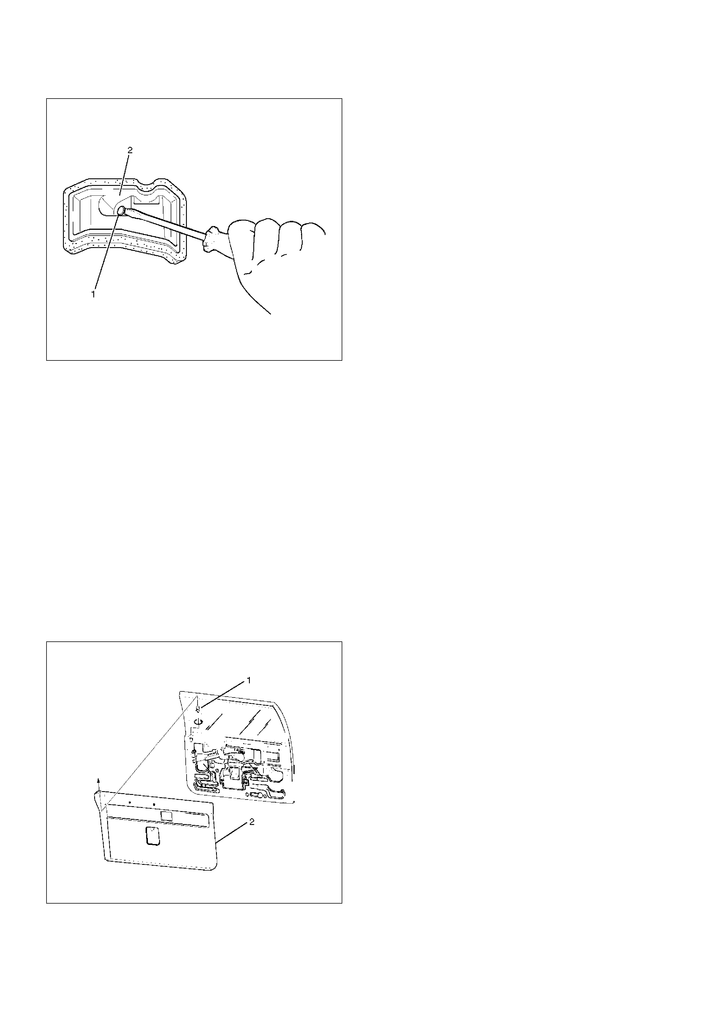
2. Remove the door trim panel.
3. Remove the waterproof sheet.
Refer to the Front Window Regulator, Glass And
Glass Run in Body Structure section.
4. Raise the glass up to the uppermost position, and
then remove the rear guide rail.
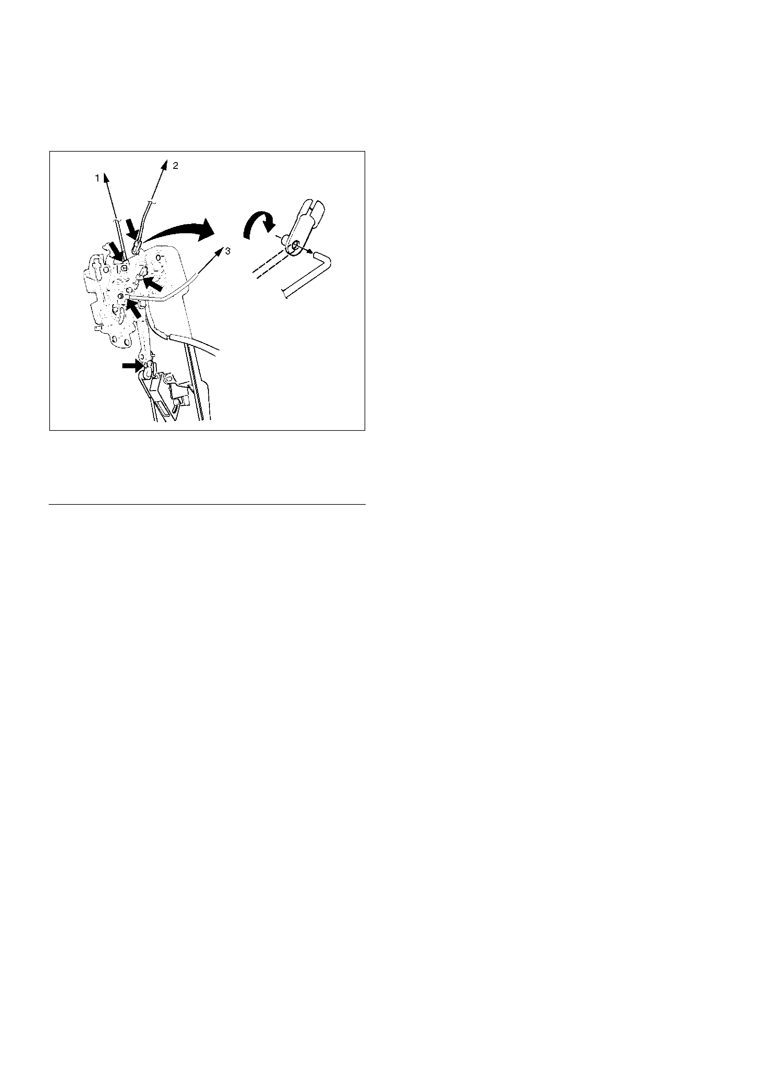
5. Disconnect the door lock switch connector (w/power
door lock) and locking links (arrow marks positions),
then remove the door lock assembly fixing screws
and door lock assembly.
632RS004
EndOFCallout
Installation
To install, follow the removal steps in the reverse order,
noting the following points.
1. Apply chassis grease to the lock assembly and
striker moving surface.
2. Tighten the door lock assembly fixing screws to the
specified torque.
Torque: 7N·m(0.7kg·m/61lbin)
3. Check that the door lock operates smoothly.
Legend
(1) To Inside Lock Knob
(2) Door Lock Assembly
(3) To Actuator
(4) Door Lock Switch Connector
(5) To Inside Handle
(6) Outside Handle
Front Outside Handle and Door Lock Cylinder
Front Outside Handle, Door Lock Cylinder and Associated Parts
632RS006
EndOFCallout
Removal
1.Disconnect the battery ground cable.
2.Remove the door trim panel.
3.Remove the waterproof sheet.
•Refer to the Front Window Regulator, Glass And
Glass Run in Body Structure section.
Legend
(1) Door Trim Panel
(2) Waterproof Sheet
(3) Outside Handle
(4) Door Lock Cylinder
(5) Clip
(6) Key Switch (W/Anti-Theft)
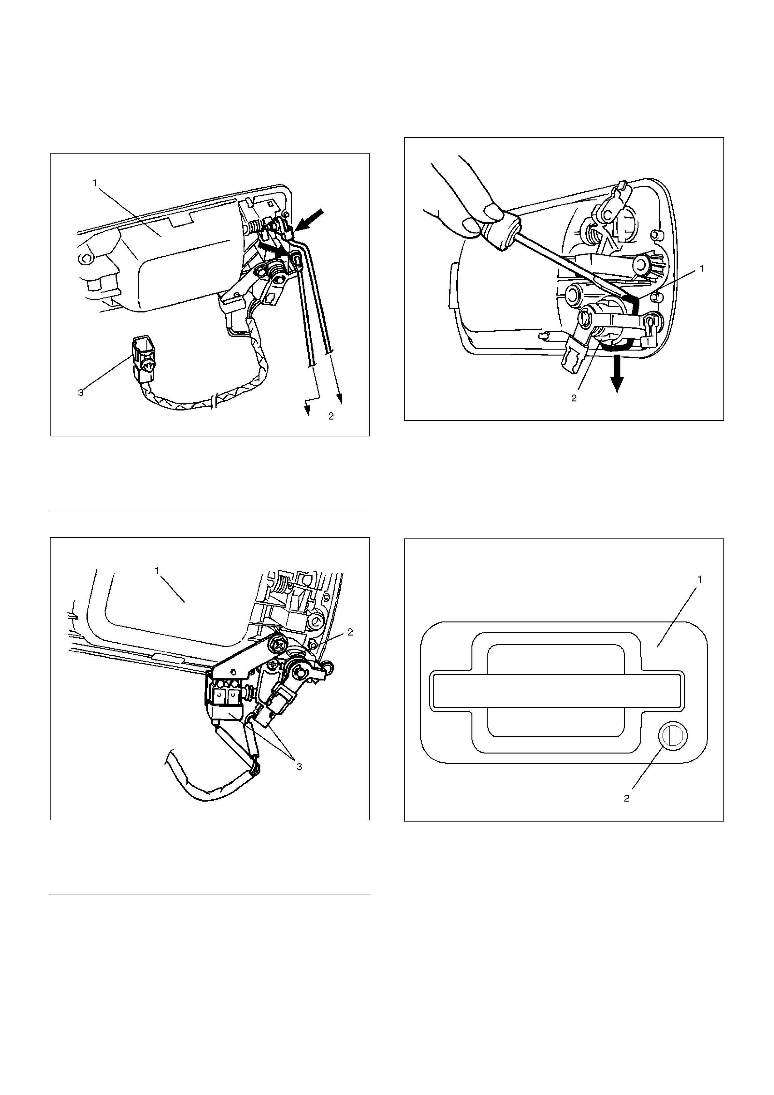
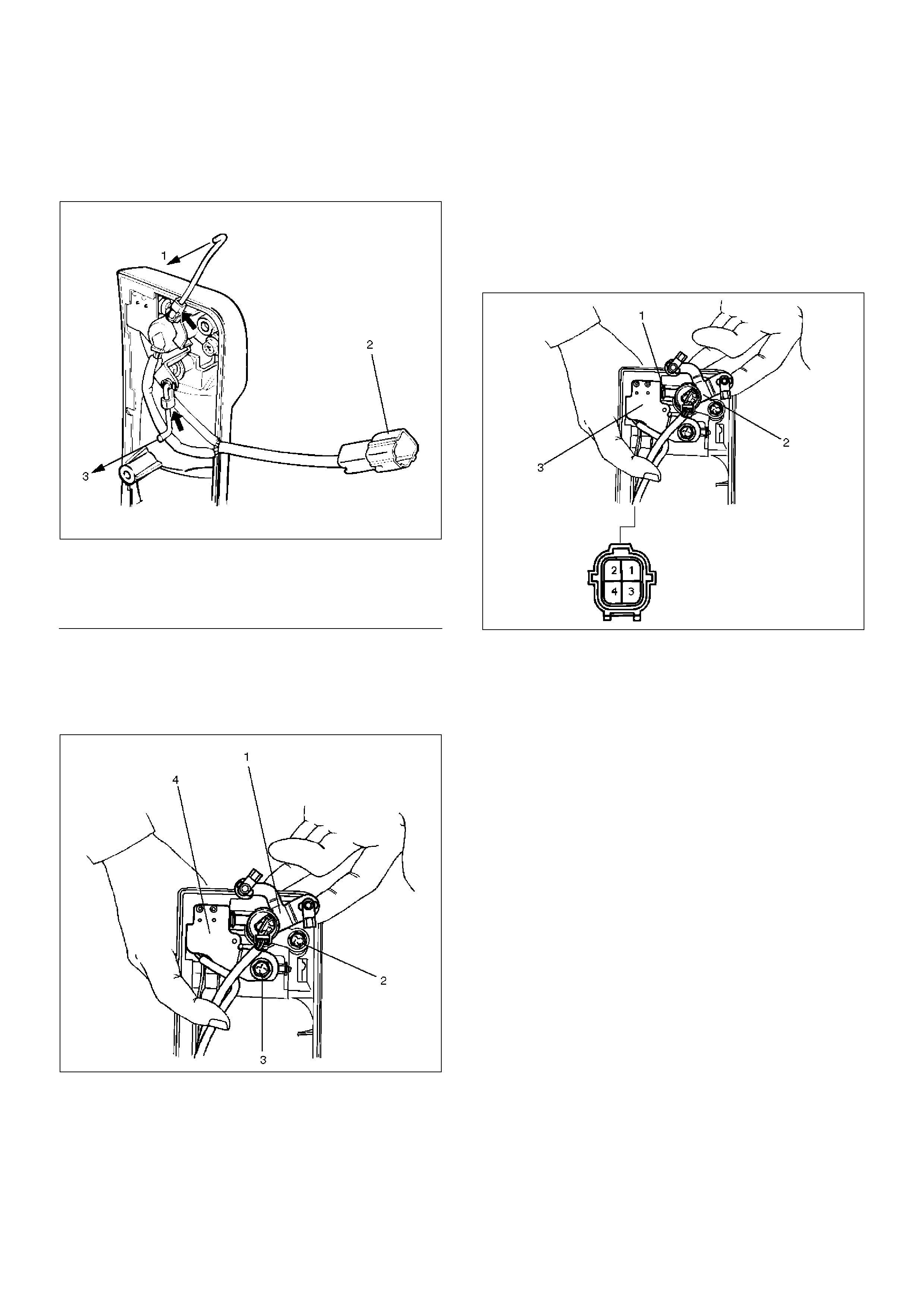
4. Disconnect the locking links (arrow marks positions)
and key switch connector (w/anti-theft) to remove
the outside handle.
632RS005
EndOFC allout
5. Remove the key Switch.
632RS007
EndOFC allout
6. Remove the fixing clip(1) to remove the door lock
cylinder(2).
632RS009
Installation
To install, follow the removal steps in the reverse order,
noting the following points.
1. Be sure to install the door lock cylinder(2) at a right
angle to the outside handle(1).
632RS008
Legend
(1) Outside Handle
(2) To Door Lock Assembly
(3) Key Switch Connector (W/Anti–Theft)
Legend
(1) Outside Handle
(2) Lock Cylinder
(3) Key Switch
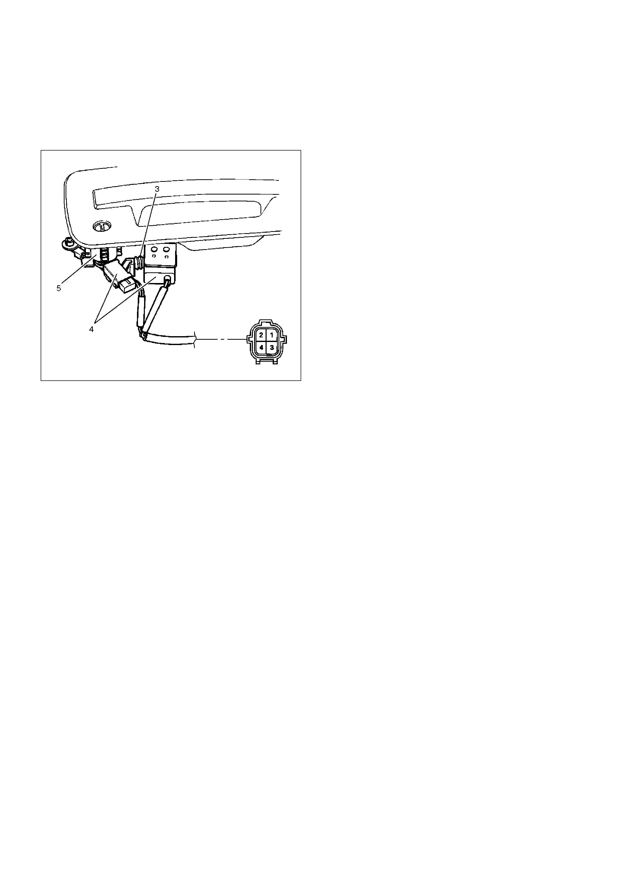
2. For the anti-theft system, be sure to install the push
rod(3) of key switch while pressing it to the door lock
cylinder(5) so that there is no continuity between the
key switch(4) side connector terminal No. D6–2 and
D6–4 (No. D16–2 and D16–4: passenger side).
632RS010
3. Tighten the outside handle and key switch fixing
bolts to the specified torque.
Torque: 9N·m(0.9kg·m/78lbin)
4. Check for smooth outside handle and lock cylinder
operation.
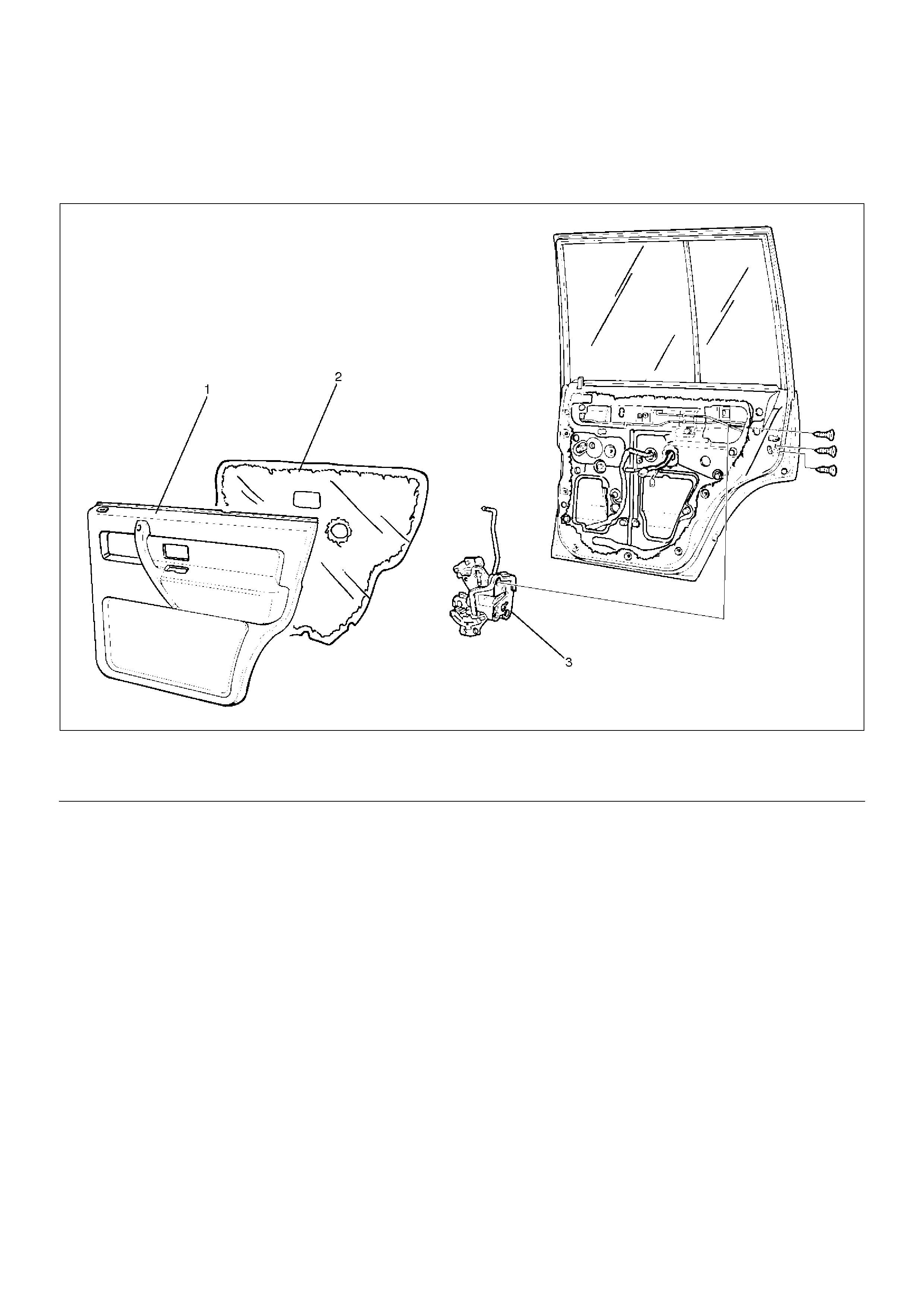
Rear Door Lock Assembly
Rear Door Lock Assembly and Associated Parts
652RW004
EndOFCallout
Removal
1.Disconnect the battery ground cable.
2.Remove the door trim panel.
3.Remove the waterproof sheet.
•Refer to the Rear Window Regulator And Glass
in Body Structure section.
Legend
(1) Door Trim Panel
(2) Waterproof Sheet
(3) Door Lock Assembly
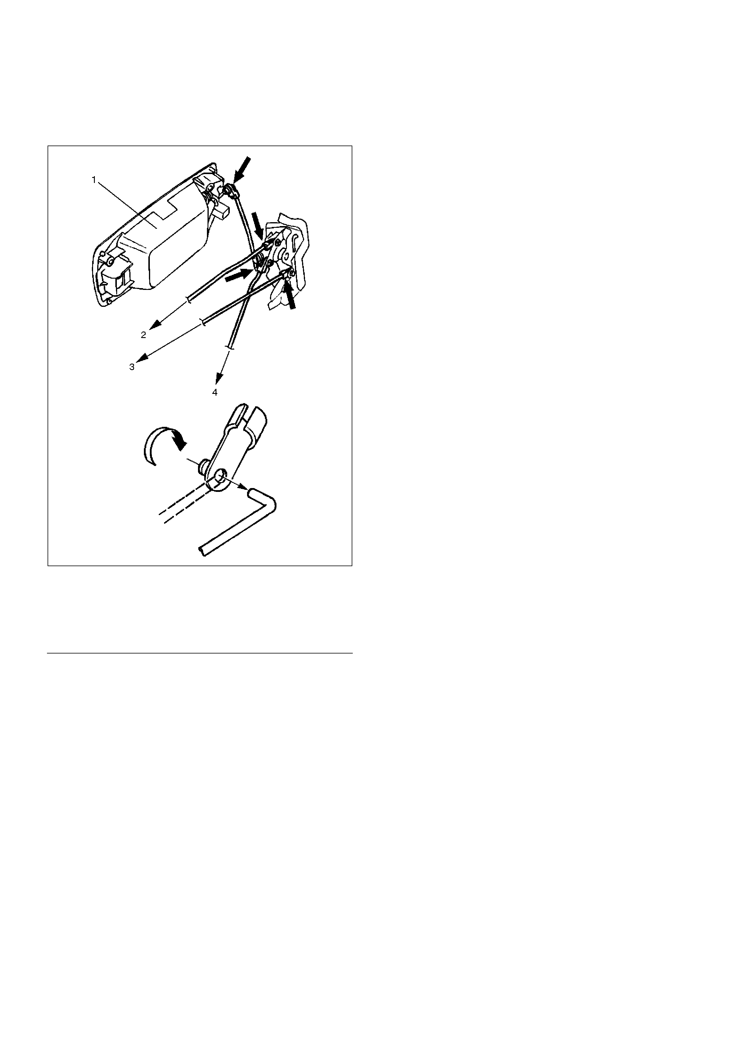
4. Disconnect the locking links (arrow marks positions)
and remove the fixing screws to remove the door
lock assembly.
652RS002
EndOFC allout
Installation
To install, follow the removal steps in the reverse order,
noting the following points.
1. Apply chassis grease to the lock assembly and
striker moving surface.
2. Tighten the door lock assembly fixing screws to the
specified torque.
Torque: 7N·m(0.7kg·m/61lbin)
3. Check that the door lock operates smoothly.
Legend
(1) Outside Handle
(2) To Inside Lock Knob
(3) To Inside Handle
(4) To Actuator
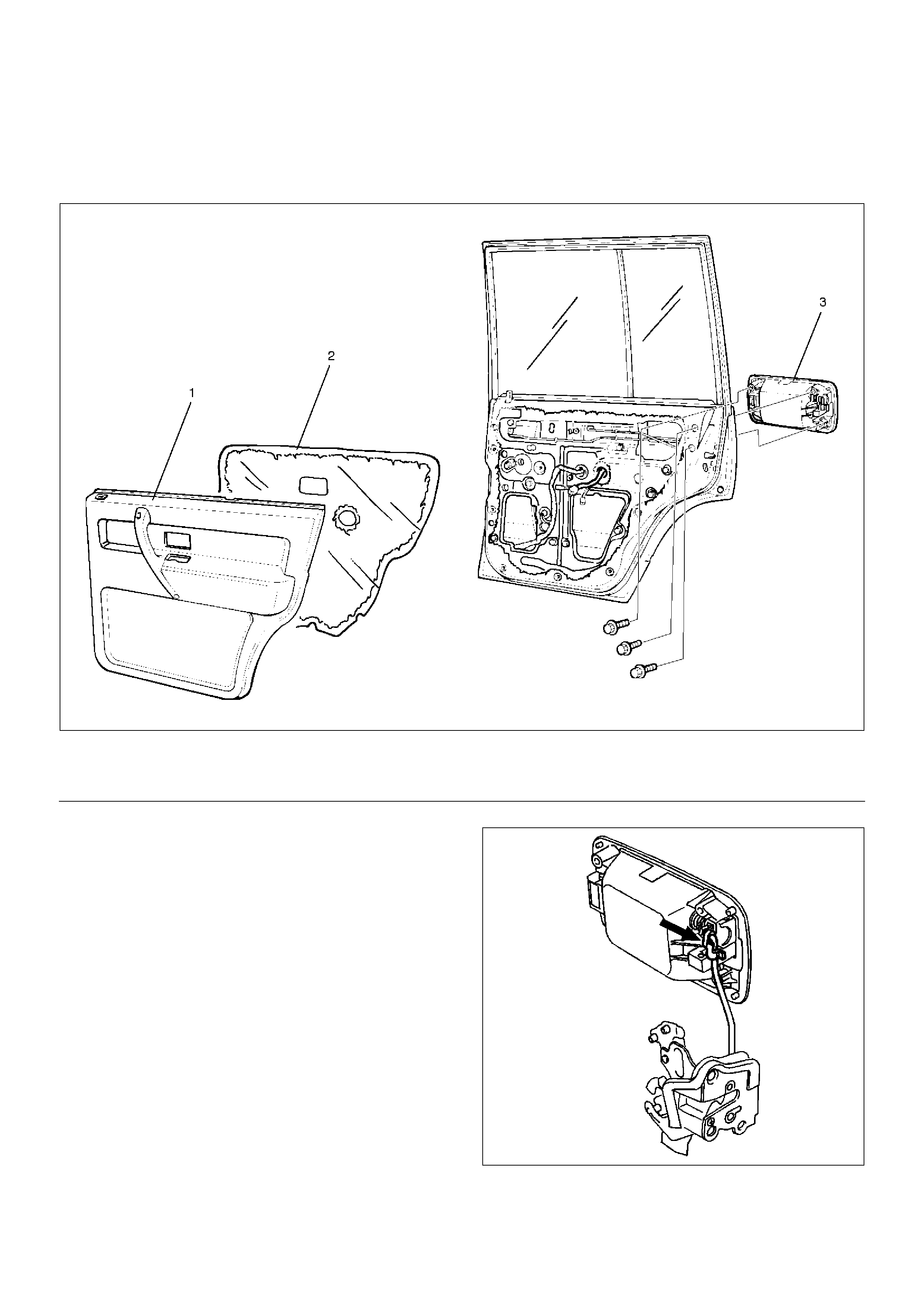
Rear Outside Handle
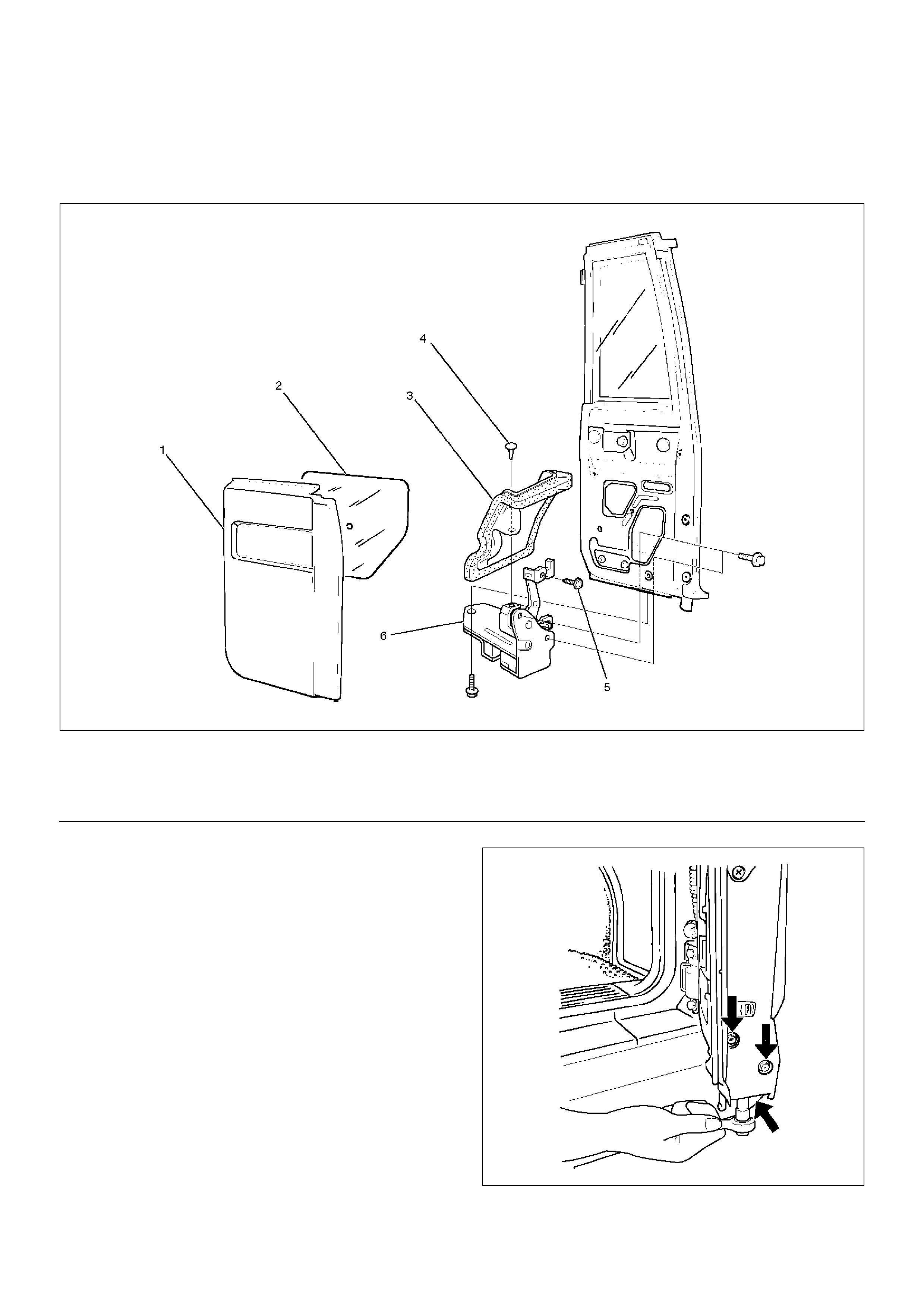
Rear Outside Handle and Associated Parts
652RW003
EndOFCallout
Removal
1.Disconnect the battery ground cable.
2.Remove the door trim panel.
3.Remove the waterproof sheet.
•Refer to the Rear Window Regulator And Glass
in Body Structure section.
4. Disconnect the locking link (arrow mark position)
and remove three fixing bolts to remove the outside
handle.
652RS003
Legend
(1) Door Trim Panel
(2) Waterproof Sheet
(3) Outside Handle
Installation
To install, follow the removal steps in the reverse order,
noting the following points.
1.Tighten the outside handle fixing bolts to the
specified torque.
Torque: 9N·m (0.9kg·m/78lbin)
2.Check that the outside handle operates smoothly.
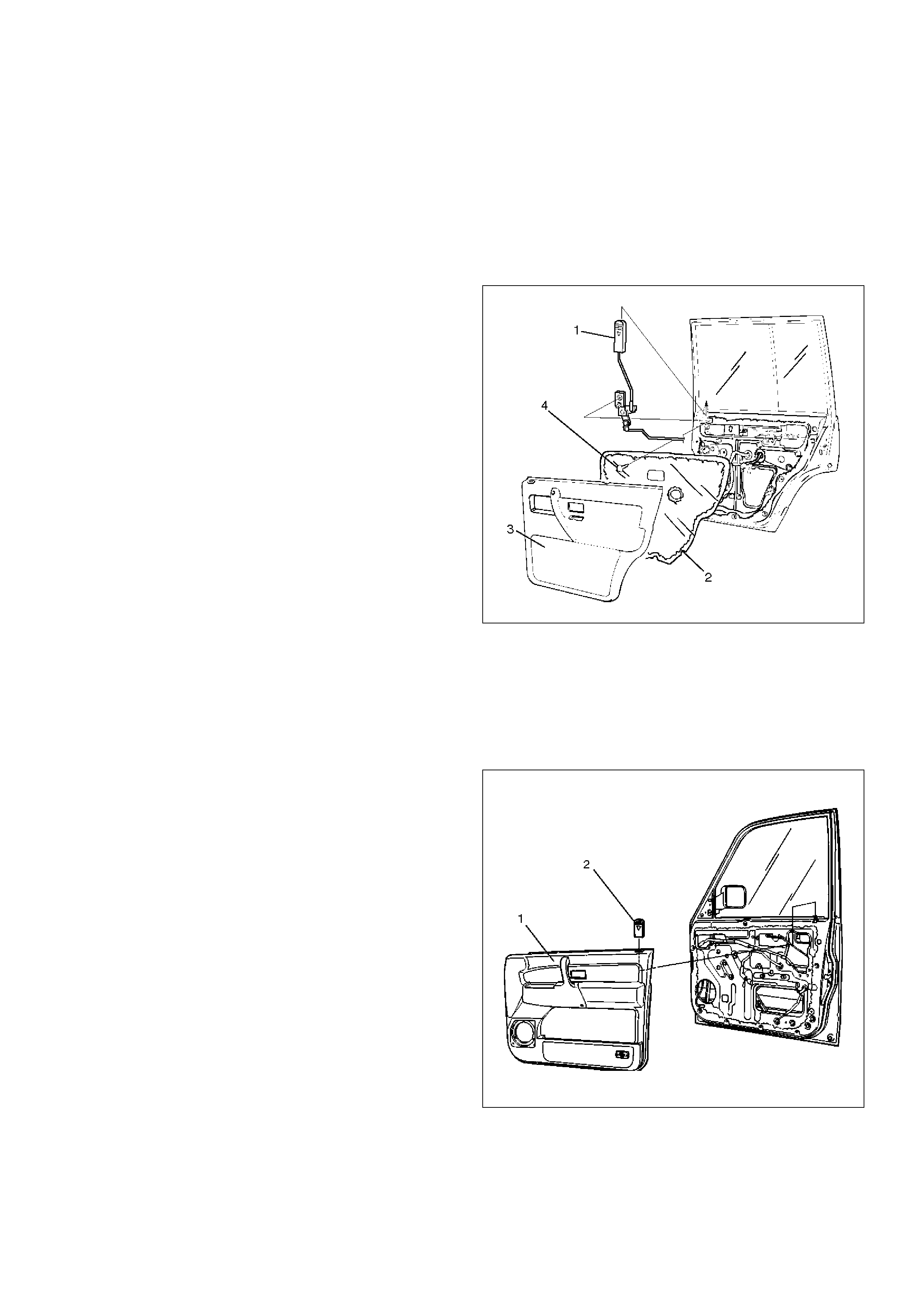
Rear Door Inside Lock Knob Link
Removal
1.Disconnect the battery ground cable.
2.Remove the door trim panel(3).
3.Remove the waterproof sheet(2).
•Refer to the Rear Window Regulator And Glass
in Body Structure section.
4.Remove the fixing screw(4) and disconnect the
locking link at the door lock assembly to remove the
rear door inside lock knob link(1).
655RW009
Installation
To install, follow the removal steps in the reverse order.
Door Inside Lock Knob
Removal
1.Disconnect the battery ground cable.
2.Remove the door trim panel(1).
•Refer to the Front & Rear Door Trim Panel in
Exterior/Interior Trim section.
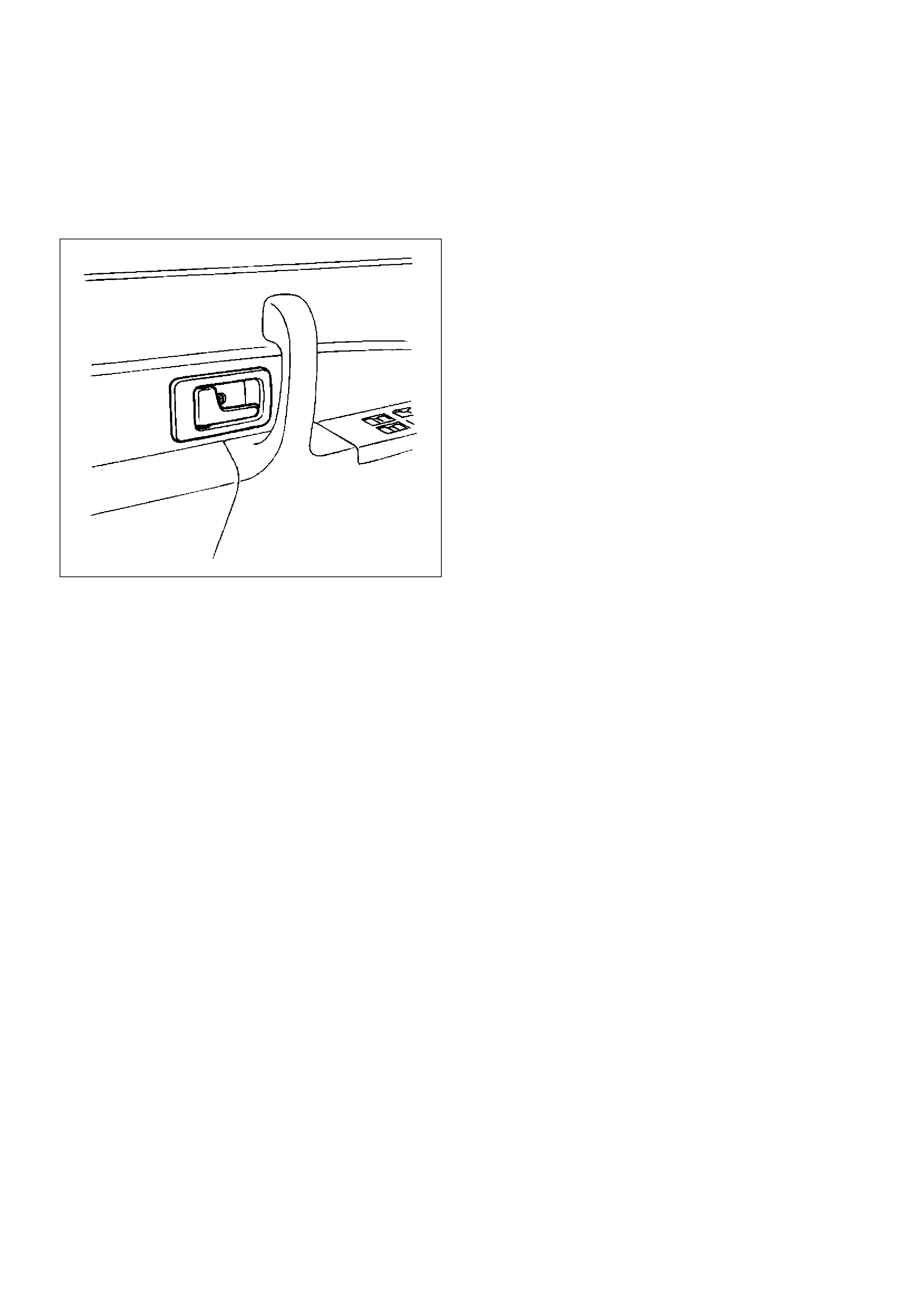
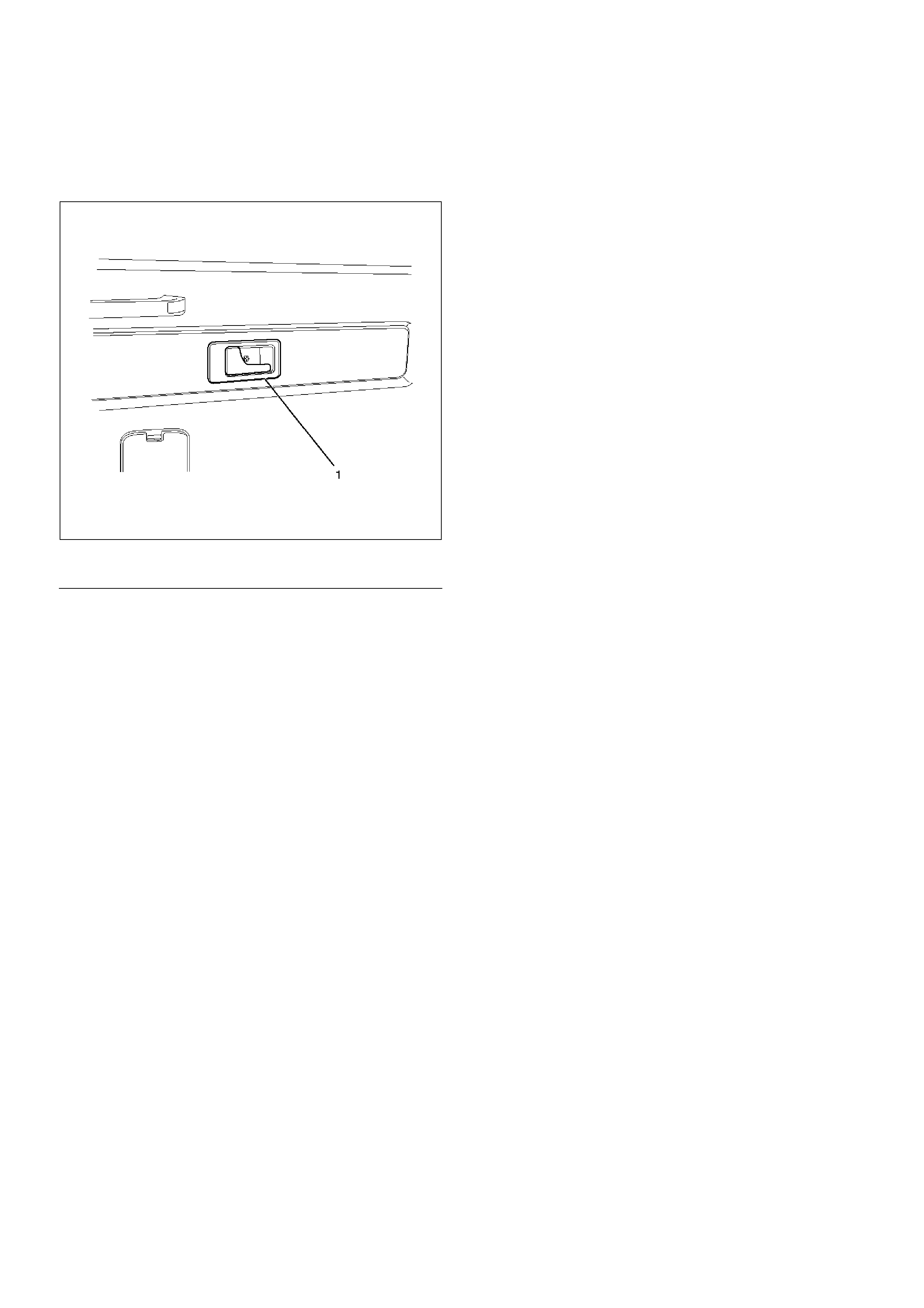
3. Turn the door inside lock knob counterclockwise
and then remove the door inside lock knob (2).
632RS011
Installation
To install, follow the removal steps in the reverse order.
Tailgate Lock Assembly (LH)
Tailgate Lock Assembly (LH) and Associated Parts
684RW008
EndOFCallout
Removal
1.Disconnect the battery ground cable.
2.Remove the tailgate trim panel (LH).
•Refer to the Tailgate Trim Panel (LH) in Exterior/
Interior Trim section.
3. Taking notice of the tailgate harness, peel the
waterproof sheet off the tailgate panel carefully and
then remove the waterproof sheet.
684RS005
Legend
(1) Tailgate Trim Panel(LH)
(2) Waterproof Sheet
(3) Tailgate Lock Assembly
4. Disconnect the locking links (arrow marks
positions), remove three fixing screws and then
remove the tailgate lock assembly (LH).
683RW015
EndOFC allout
Installation
To install, follow the removal steps in the reverse order,
noting the following points.
1. Apply chassis grease to the lock assembly and
striker moving surface.
2. Tighten the tailgate lock assembly fixing screws to
the specified torque.
Torque: 7N·m(0.7kg·m/61lbin)
3. Check that the tailgate lock operates correctly after
installing it.
Legend
(1) To Inside Lock Knob
(2) To Actuator
(3) To Inside Handle
Tailgate Lock Assembly (RH)
Tailgate Lock Assembly (RH) and Associated Parts
684RW006
EndOFCallout
Removal
1.Disconnect the battery ground cable.
2.Remove the tailgate trim panel (RH).
•Refer to the Tailgate Trim Panel (RH) in Exterior/
Interior Trim section.
3. Peel the waterproof sheet off the tailgate panel
carefully and then remove the waterproof sheet.
4. Remove three fixing bolts and then remove the
tailgate lock assembly (RH).
683RW009
5. Remove the tailgate lock seal fixing clip(1) and then
remove the tailgate lock seal(2).
Legend
(1) Tailgate Trim Panel (RH)
(2) Waterproof Sheet
(3) Tailgate Lock Seal
(4) Clip
(5) Screw
(6) Tailgate Lock Assembly (RH)
683RW008
Installation
To install, follow the removal steps in the reverse order,
noting the following points.
1.Apply chassis grease to the lock assembly and
striker moving surface.
2.Tighten the tailgate lock assembly fixing bolts to the
specified torque.
Torque: 11N·m(1.1kg·m/95lbin)
3.Check that the tailgate lock operates correctly after
installing it.
Tailgate Inside Lock Knob
Removal
1.Disconnect the battery ground cable.
2.Remove the tailgate trim panel (LH)(2).
•Refer to the Tailgate Trim Panel (LH) in Exterior/
Interior Trim section.
3. Take care of cushion to turn the lock knob
counterclockwise and then remove the tailgate
inside lock knob(1).
683RW014
Installation
To install, follow the removal steps in the reverse order.
Tailgate Outside Handle and/or Tailgate Lock Cylinder
Tailgate Outside Handle and/or Tailgate Lock Cylinder and Associated Parts
684RW007
EndOFCallout
Removal
1.Disconnect the battery ground cable.
2.Remove the tailgate trim panel.
3.Remove the waterproof sheet.
•Refer to the Tailgate Lock Assembly (LH) in this
section.
4. Remove the grommet.
Legend
(1) Tailgate Trim Panel (LH)
(2) Waterproof Sheet
(3) Grommet
(4) Tailgate Lock Cylinder
(5) Tailgate Outside Handle
(6) Key Switch (W/Anti–Theft)
5. Disconnect the locking links (arrow marks
positions), key switch connector (w/anti-theft) and
remove three fixing bolts to remove the tailgate
outside handle.
683RW016
EndOFC allout
6. Remove the key switch fixing bolt(3) to remove the
key switch (w/anti-theft) (4) from the tailgate lock
cylinder (1).
And remove the tailgate lock cylinder fixing bolt(2) to
remove the tailgate lock cylinder.
683RS008
Installation
To install, follow the removal steps in the reverse order,
noting the following points.
1. For the anti-theft system, install the push rod(1) of
the key switch(3) to the key cylinder(2) while
pressing it so that there is not continuity between
the key switch side connector terminals No. G5–2
and G5–4 as shown in the figure.
683RS009
2. Tighten the outside handle and key cylinder fixing
bolts to the specified torque.
Torque: 9N·m(0.9kg·m/78lbin)
3. Check that the outside handle and key cylinder
operate correctly after installing them.
Legend
(1) To Actuator
(2) Key Switch Connector (W/Anti–Theft)
(3) To Lock Assembly
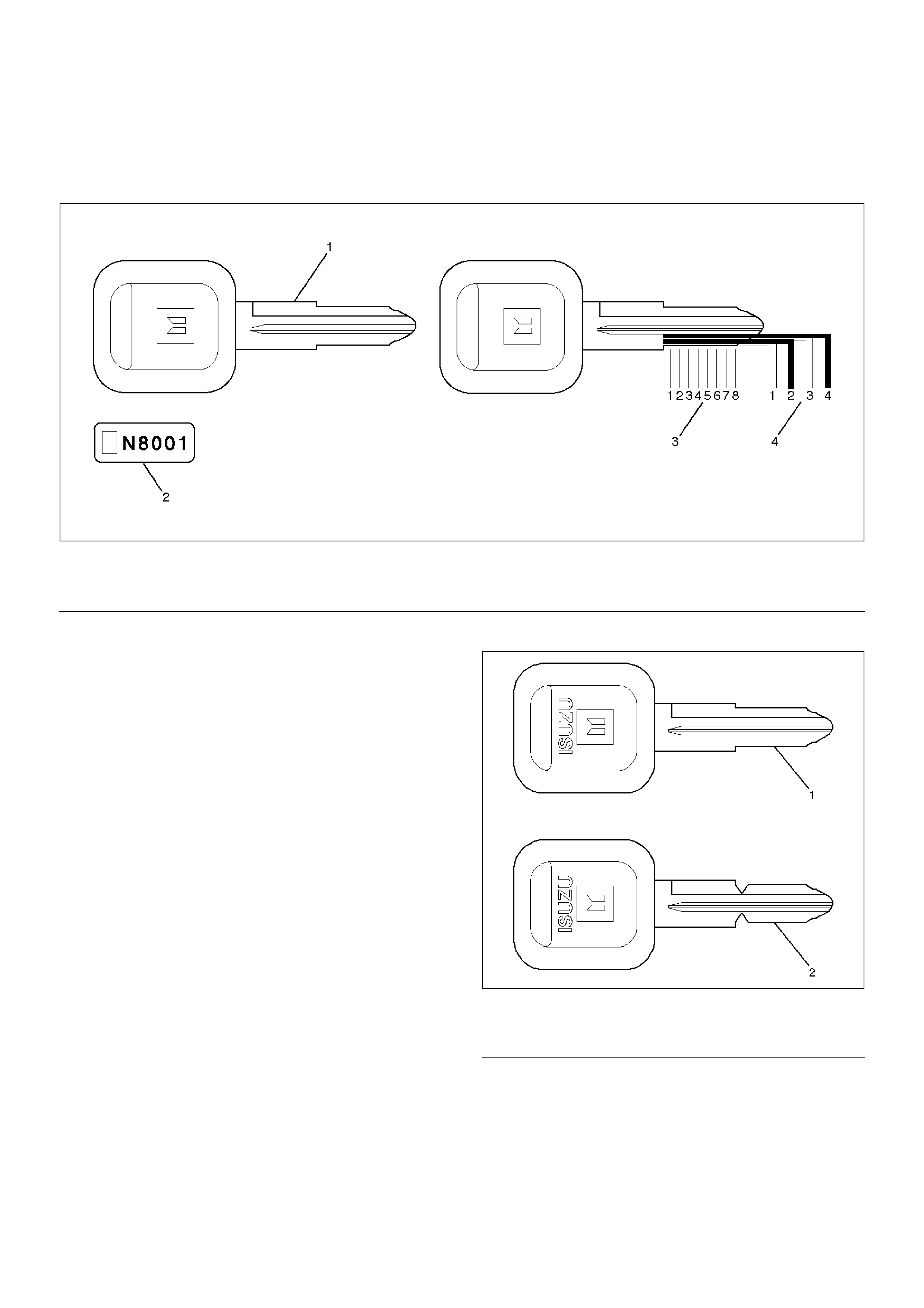
Key
Key Coding
730RW001
EndOFCallout
One key is used for the ignition, door, and tailgate lock
cylinders. The keys are cut on both edges to make them
reversible.
Key identification is obtained from the five character key
code stamped on the key code tag. From this key code,
the key code cutting combination can be determined
from a code list (available to owners of key cutting
equipment from suppliers).
If key codes are not available from records or tags, the
key code can be obtained from the right hand door lock
cylinder (if lock has not been replaced). Lock cylinders
supplied by the factory as service parts are unmarked.
If the original key is available, the key code cutting
combination can be determined by laying the key on the
diagram shown in the figure.
Key Styles
730RS010
EndOFC allout
The keys come in styles A or B depending on the key
code cutting combination. When the first position in the
combination is a 1, 2 or 3, Style A is used. When the
first position is a 4, Style B (factory pre-cut key) is used.
Legend
(1) Key(Actual Size)
(2) Key Code Tag
(3) Position
(4) Level
Legend
(1) Blank Key Style “A”
(2) Blank Key Style “B”
Power Door Lock System
General Description
The circuit consists of the door lock (& power window)
switch, door lock actuator for the front and rear door,
tailgate lock actuator and the door lock key switch. The
front door lock switch –LH is always provided with
battery voltage.
The key or the inside lock button on the both driver's
and the front passenger's door can activate the lock
mechanism of all the doors (including the tailgate).
When the driver's door lock switch or the front
passenger's door lock switch is turned on, current flows
for about one second to the door lock actuator of each
door connected in parallel with the front door lock (&
power window) switch –LH to activate the actuator to
lock and unlock the doors.
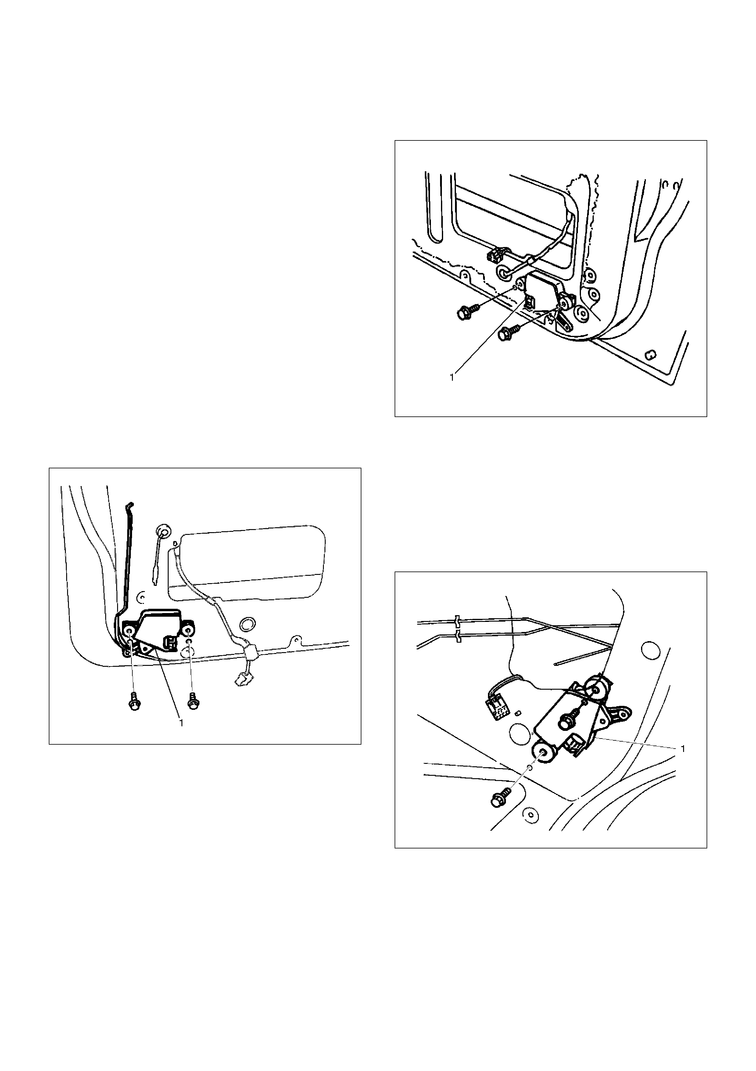
Front Door Lock Actuator Removal
1.Refer to the Front Door Lock Assembly removal
procedure in this section.
2. Remove the door lock actuator(1).
632RS021
632RS020
Front Door Lock Actuator Installation
To install, follow the removal steps in the reverse order.
Rear Door Lock Actuator Removal
1.Refer to the Rear Door Lock Assembly removal
procedure in this section.
2. Removal the door lock actuator(1).
632RS019
Rear Door Lock Actuator Installation
To install, follow the removal steps in the reverse order.
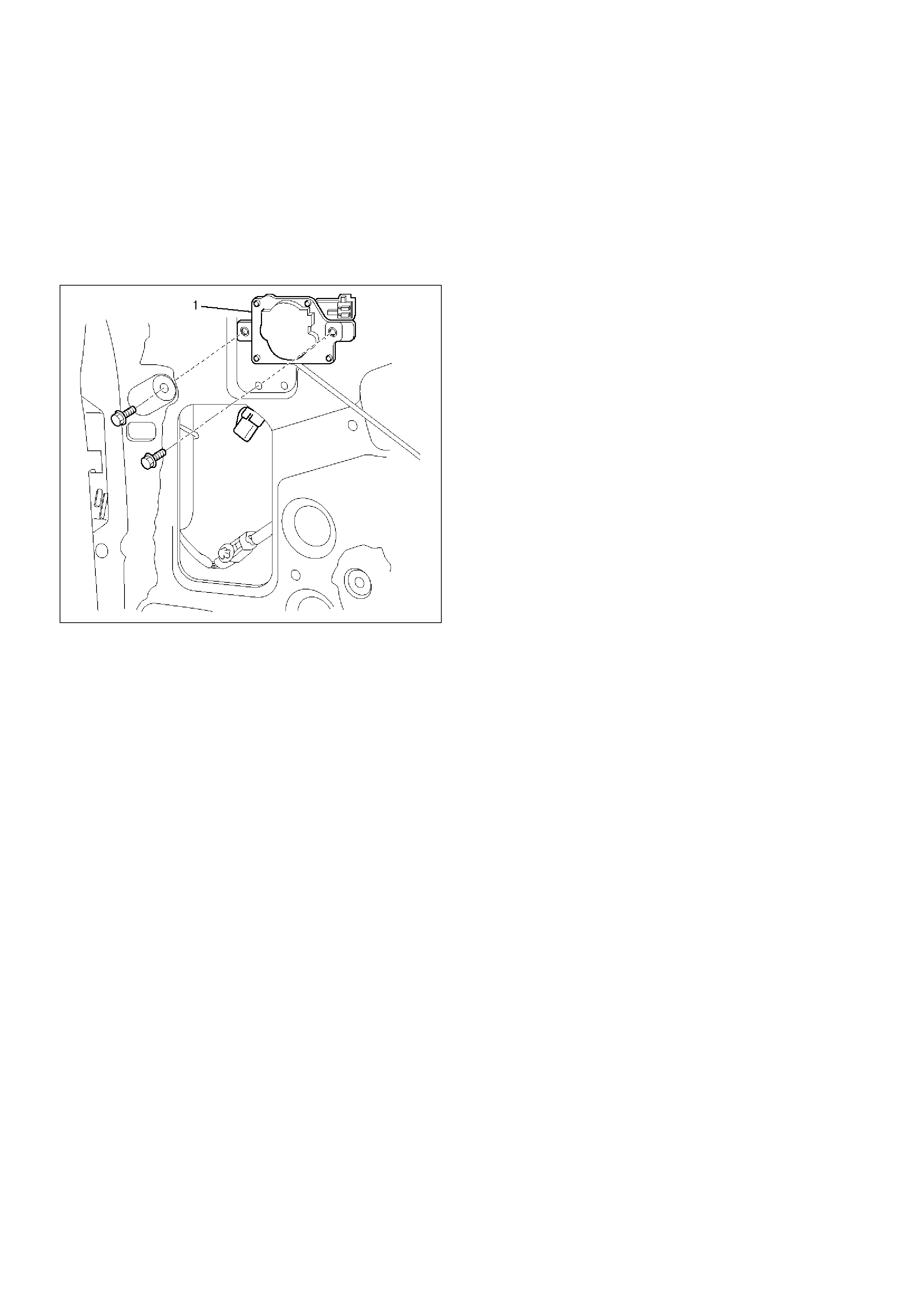
Tailgate Lock Actuator Removal
1.Refer to the Tailgate Lock Assembly (LH) removal
procedure in this section.
2. Remove the tailgate lock actuator(1).
632RY00002
Tailgate Lock Actuator Installation
To install, follow the removal steps in the reverse order.

Main Data and Specifications
Torque Specifications
Application N·m Kg·m LbFt LbIn
Front Door Lock Assembly Fixing Screws 7 0.7 — 61
Front Outside Handle and Key Switch Fixing Bolts 9 0.9 — 78
Rear Door Lock Assembly Fixing Screws 7 0.7 — 61
Rear Outside Handle Fixing Bolts 9 0.9 — 78
Tailgate Lock Assembly (LH) Fixing Screws 7 0.7 — 61
Tailgate Lock Assembly (RH) Fixing Bolts 11 1.1 — 95
Tailgate Outside Handle and Key Cylinder Fixing Bolts 9 0.9 — 78