
SECTION 11A - ENGINE IMMOBILISER SYSTEM
6VE1 PETROL ENGINE
General Information
System Components
Engine Start Sequence
System Programming
TECH 2 Operation
Transponder-Key Programming
Erasing Transponder Keys
Programming The Immobiliser Control Unit (ICU)
Programming The Engine Controller
Programming The ICU And The PCM
Enable Programming - TIS 2000
Diagnostic Trouble Codes
Engine Will Not Crank No DTC Set
DTC B8011 Transponder Key Problem
DTC B8012 Wrong Transponder Key
DTC B8013 Immobiliser Not Programmed
DTC B8014 No Transponder Key Programmed
DTC B8015 Vehicle Speed Sensor
Signal Low (<2.5v)
DTC B8016 Vehicle Speed Sensor
Signal High (>2.5v)
DTC B8017 No PCM Request Received
DTC B8023 Antenna Coil Open Circuit
DTC B8024 Wrong Transponder Response
DTC B8025 Wrong Engine Request Signal
DTC B8026 Relay Output Low
DTC B8027 Relay Output High
DTC B8055 EEPROM Error
Immobiliser Control Unit Harness Connector
Wiring Diagram
Techline
Techline

General Information
The Engine Immobiliser System is designed to provide ‘Drive-away’ protection by electronically disabling the fuel
system and the starter motor relay. It is a passive system, requiring no action on the part of the driver other than
removing the ignition key from the switch.
When the ignition is turned ‘ON’, a process of data transfer takes place between the transponder type ignition key, the
Immobiliser Control Unit (ICU) and the Engine Control Module (PCM).
If any transmitted data is incorrect or missing, the ICU prevents Immobiliser Relay operation - disabling the starter
motor, and the PCM will disable the Fuel Injectors. When the engine has been shut down for more than twelve
seconds, both the request and the immobiliser signal change on the next ignition key cycle, the complex data
exchange taking place again.
If there is a malfunction - either an incorrect transponder signal or no communication between the components, engine
is disabled, the ‘CHECK ENGINE’ lamp in the instrument cluster will blink rapidly and the relevant Diagnostic Trouble
Code/s (DTC/s) stored in the ICU and the PCM.

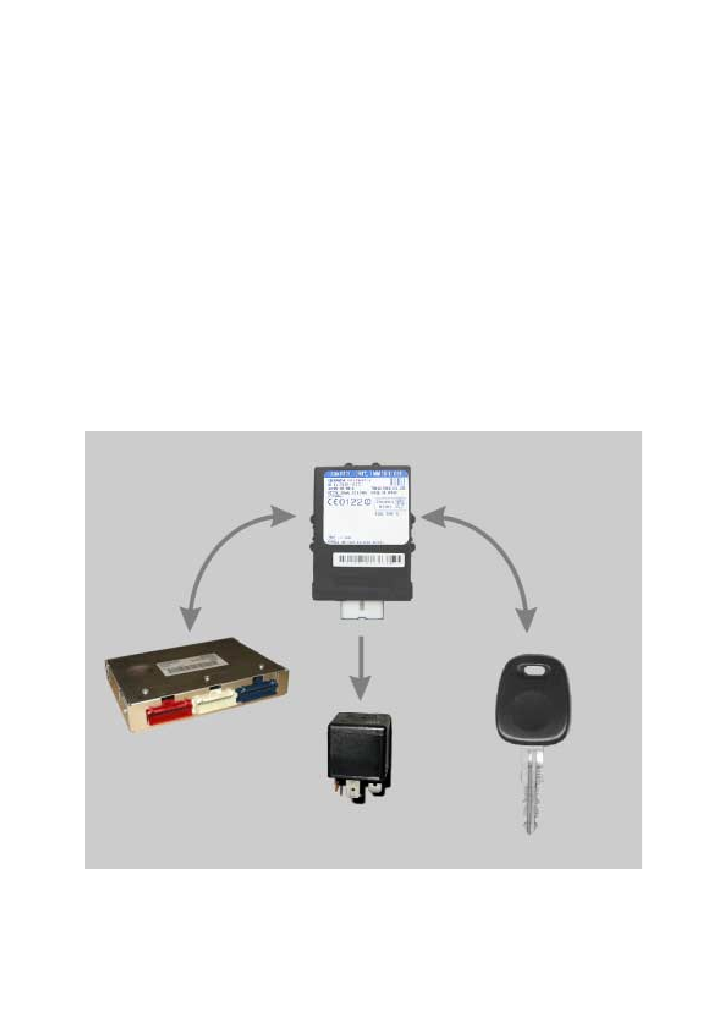
System Components
The main system components are:
• Transponder Key
• Coil Antenna
• Immobiliser Control Unit (ICU)
• Immobiliser Relay
• Engine Control Unit (PCM)
• Associated wiring harnesses, connectors and fuses
Transponder Key
The system uses a conventional mechanical-cut ignition
key containing a minature transponder (transmitter/
responder) embedded in the plastic handle.
Each transponder is programmed with it’s own specific
ID code during manufacture. Up to 1018 codes are
available with this system, making code duplication
almost impossible.
The transponder circuit in the key does not require
batteries - the operating signal is provided cordlessly by
the ICU supplying a high frequency (133 kHz) AC
voltage signal to the coil antenna.
Encapsulated by the hard plastic of the key head, the
transponder is the most durable part of the ignition key.
The module is initially programmed with two
transponder codes, corresponding to the two keys
supplied with the vehicle. Should a key be lost, or an
additional key required, uncoded keys may be
programmed into the system with the aid of TECH 2. A
maximum of 5 transponder codes can be stored in the
ICU.
Due to the complex nature of the coded signals
transmitted between the it is recommended to replace
existing ignition keys when the ICU is replaced.
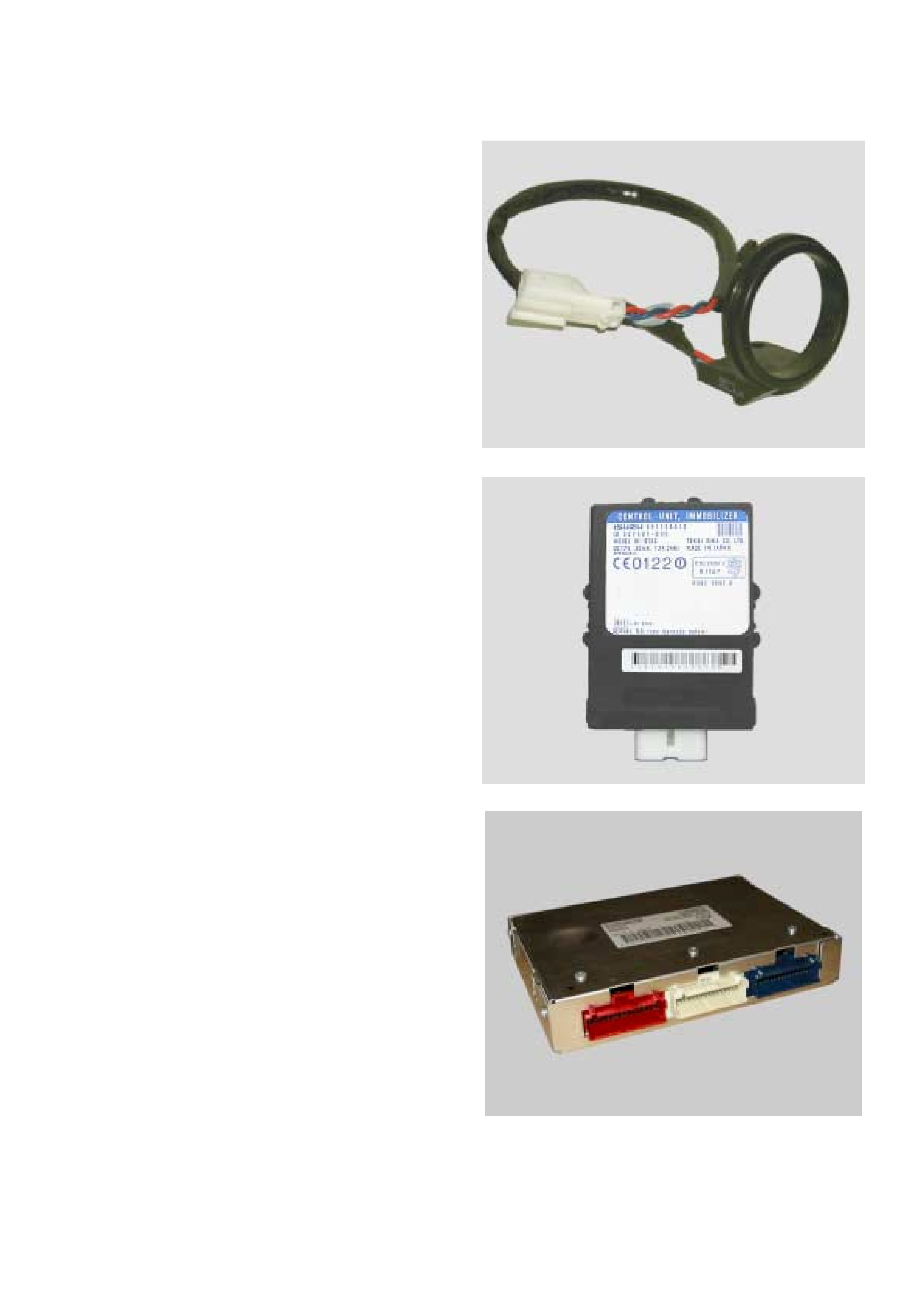
Coil Antenna
A non-contact radio frequency is used to transfer
information between the transponder key and the
Immobiliser Control Unit. Surrounding the ignition lock is
a dipole antenna, which is connected to the ICU pins 3
& 9 by a wiring harness.
The antenna is designed to have a very limited range,
ensuring that only the key in the ignition lock can
communicate with the ICU. This excludes the possible
interference from other transponder keys in the vehicle.
The antenna is accessed by removing the steering
column shroud. Apart from a continuity test on the coil
winding, substitution with a known good part is the only
applicable diagnostic procedure.
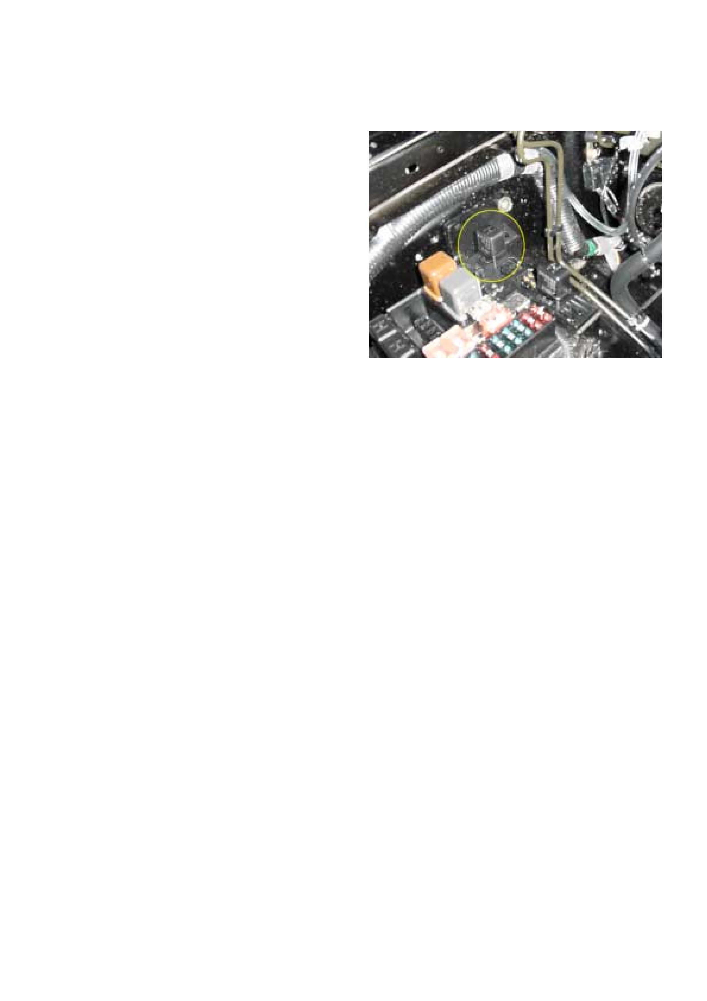
Immobiliser Control Unit (ICU)
The Immobiliser Contol Unit (ICU) is located to the right
of the glovebox opening, behind the passenger lower
instrument panel. The ICU is powered at all times from
the 10A Clock (B) Fuse and receives an ignition ‘ON’
signal from 15A Engine Fuse.
Communication between the ICU and the PCM takes
place on the Vehicle Speed Sensor (VSS) signal wire
(ICU pin 6) to PCM pin D7, and on the ‘CHECK
ENGINE’ Lamp (CEL) control circuit (PCM pin A13 to
ICU pin 7 and Instrument Cluster pin A6)
Note:
The ICU MUST be RESET before removal from the
vehicle.
If the ICU and PCM are replaced at the same time, the
ICU MUST be programmed BEFORE the Immobiliser
function of the PCM can be activated.
Engine Control Module
The Delphi PCM is located in the front passenger side
of the engine compartment, immediately behind the
aircleaner assembly. .
If the the transponder key rolling code does not match
the PCM’s calculated code, the PCM will immobilise the
engine by:
•Disabling the fuel injectors.
•Commanding 0kPa Rail Oil Pressure.
•Removing the Immobiliser Relay ground path.
Note:
A replacement PCM must programmed — Refer to
Section 0C1 - Service programming System.
The replacement PCM must be linked to the ICU for
correct operation. Refer to System Programming in this
section.
Immobiliser Relay
The Immobiliser Relay is located in the engine
compartment Main Fuse & Relay Box. One side of the
relay solenoid windings is connected to power via the
15A Engine Fuse , and the other side connected ICU
pin 10. Pin 4 of the ICU is connected to ground.
When the ignition key is in the crank position, and the
ICU has received a valid transponder key signal, the
ICU will provide the path to ground, energising the relay
windings.
When enabled by the ICU, the Immobiliser Relay allows
the starter motor relay to be energised.
Engine Start Sequence
Before the system will allow engine operation, the following sequence of data transfer and code evaluation must take
place:
1. When the ignition is turned ON, ICU supplies a high frequency (133kHz) AC voltage signal to the key via the
antenna.
2. The transponder code is transmitted to the ICU.
3. The ICU checks the transponder code and enables the Immobiliser Relay in the underbonnet Fuse & Relay box.
4. The PCM generates and transmits a RANDOM code to the ICU.
5. The ICU receives the RANDOM code from the PCM and transmits the code to the transponder.
6. The transponder calculates a ROLLING code based on the RANDOM code.
7. The transponder transmits the ROLLING code to the PCM via the ICU.
8. The PCM compares the transferred ROLLING code with it’s calculated ROLLING code.
9. If both codes match, the PCM will transmit a fuel enable signal to the Pump Control Unit.
10. The engine cannot be started during the data transfer and code evaluation process. If any of the above steps are
unsuccessful, all relevant engine functions will remain disabled.

System Programming
Programming of the Immobiliser system is performed with TECH-2 when:
•The Immobiliser Control Unit is replaced.
•The Immobiliser Control Unit is reset.
•The Engine Control Unit is replaced.
•Additional ignition keys are required.
•An ignition key has been lost.
Prior to commencing the programming sequence, the technician will require:
•The Vehicle Identification Number.
•The vehicle security code from Holden TAS
•The mechanical key number.
To enable the completion of the programming sequence, the technician will require:
•Permission from TIS 2000
Security Data
The following codes/data are stored in the ICU reference memory during vehicle production:
•The Vehicle Identification Number.
•The vehicle security code.
•The mechanical key number.
•Engine type
•Transponder code/s
The security code cannot be deleted or altered with TECH-2. The transponder code/s and engine type are processed
internally only and are not displayed on TECH-2. The Vehicle Identification Number and mechanical key number are
stored as further information for vehicle identification and can be displayed on TECH-2.
Security Code
The 4-digit security code prevents unauthorised programming and access to the data in the ICU via TECH-2. The
security code is programmed into the ICU.
Programming the Security Code
New Immobiliser Control Units do not contain a programmed security code. If the ICU is replaced, the security code for
that vehicle must be obtained, and then programmed into the ICU with TECH-2.
Replacement of the Immobiliser Control Unit (ICU)
Due to the complex nature of the coded signals transmitted between the key and the ICU, it is necessary to replace
both existing ignition keys when the ICU is replaced.
Resetting of the Immobiliser Control Unit (ICU)
Resetting of the ICU may necessitate replacement of either or both existing ignition keys. This situation is most likely
to occur if the ICU is swapped from one vehicle to another.
The ICU MUST be reset PRIOR to removal from the vehicle. Failure to do so will result in erratic or failed
reprogramming of the Immobiliser System.
Replacement Of The Powetrain Control Module (Pcm)
Replacement PCM’s must be programmed. Refer to Section 0C1 — Service Programming System for complete
instructions on this operation.

Loss of a Transponder Key
If a transponder key is lost, all transponder codes in the Immobiliser Control Unit must be erased to prevent
unauthorised use. This will ensure that, whilst the 'lost' key will allow access to the vehicle, it cannot be used to start
the vehicle.
After erasing all existing codes, the transponder codes of the remaining keys and the new transponder key can be
programmed.
NOTE:
• Programming Approval must be obtained from TIS, using the `Enable Programming" option, before either
control unit or transponder key programming is performed.
• Once Programming Approval has been obtained, TECH-2 will allow five programming operations. Once all five
programming operations have been used, Programming Approval will then have to be obtained again.
• If the five programming operations are not used within 24hrs, they will be cleared from TECH-2, requiring
further Programming Approval to be obtained.

TECH 2 Operation
With the latest software loaded, connect TECH 2 to the
vehicle, turn on TECH 2.
NOTE: Due to the constant evolution of TECH 2
software, the screens shown in this section may
differ slightly from those displayed for the vehicle
being tested.
When the TECH 2 introduction screen appears, press
ENTER.
Select: Diagnostics / MY2002 / Jackaroo / F2: Body /
Immobiliser
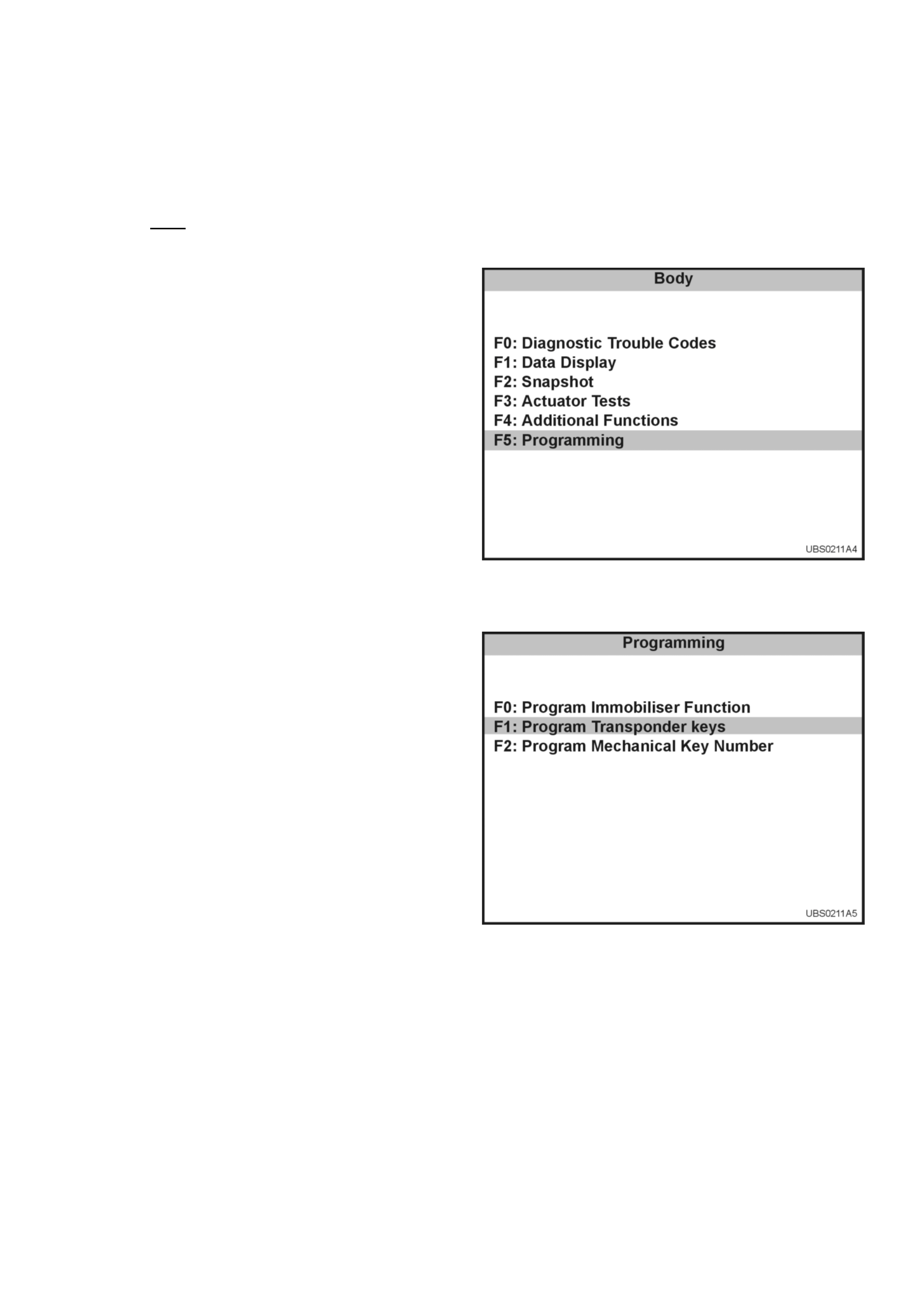
The following modes and sub-modes are now available:
F0: Diagnostic Trouble Codes
• F0: Read DTC Info Ordered By Priority
• F1: Read DTC Info As Stored By PCM
• F2: Clear DTC Information
F1: Data Display
F2: Snapshot
F3: Actuator Test
• F0: Immobiliser Relay Output Test
F4: Additional Functions
• F0: Read PCM Identification
• F1: Reset Immobiliser
• F2: Reset Engine Control Module
• F3: Erase Transponder - Keys
F5: Programming
• F0: Program Immobiliser Function
• F1: Program Transponder - Keys
Transponder-Key Programming
Programming Approval must be obtained from TIS 2000, using the "Enable Programming" option, during the
transponder key program sequence.
TECH 2 will request the Vehicle Security Number during the program sequence - this must be obtained from
Holden TAS prior to commencing this operation.
Connect TECH 2 to the vehicle:
1. Select Diagnostics / MY2002 / Jackaroo / F2:
Body.
2. Select Immobiliser
3. Select F5: Programming.
4. Select F1: Program Transponder - Keys.
5. Obtain programming approval from TIS 2000.
6. Return to F1: Program Transponder - Keys.
7. When the SPCMRITY CODE is requested,
enter the security code and press ENTER.
8. Insert a non-programmed Transponder key and
press CONFIRM.
9. 'Turn On Ignition Key' will be displayed if the
ignition is OFF.
10. The Transponder status will be displayed if the
status does not allow programming.
11. When Programming starts, 'Programming
Transponder - key' is displayed.
12. Cycle the ignition key as instructed by the
display.
13. If the programming was successful, the screen
will display'Program More Keys?'
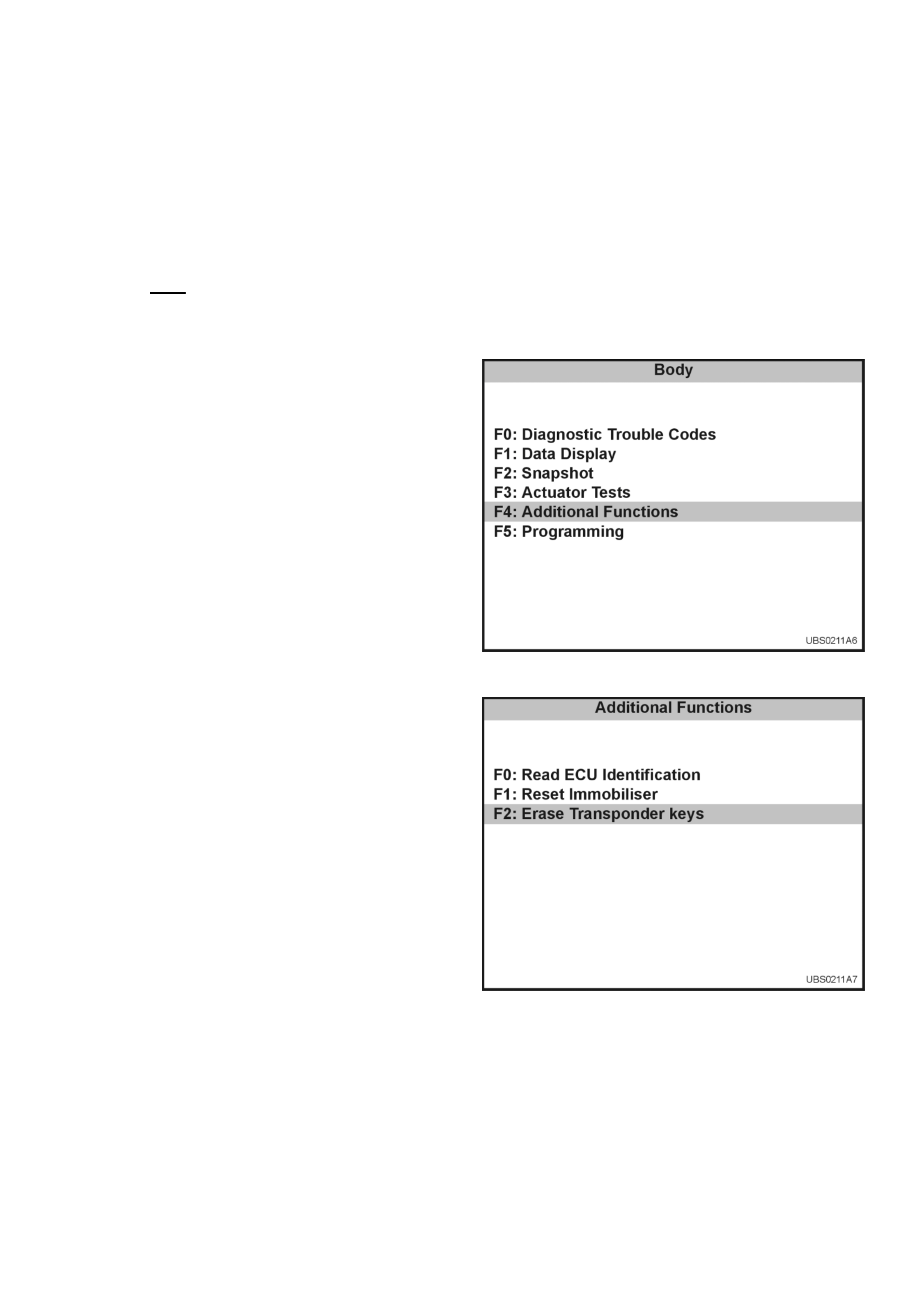
Erasing Transponder Keys
If a transponder key is lost, all transponder codes in the Immobiliser Control Unit must be erased to prevent
unauthorised use. This will ensure that, whilst the 'lost' key will allow access to the vehicle, it cannot be used to start
the vehicle.
CAUTION: This sequence erases ALL transponder-keys. Transponder-Key programming will be required before the
vehicle can be restarted.
TECH 2 will request the Vehicle Security Number during the program sequence - this must be obtained from
Holden TAS prior to commencing this operation.
Connect TECH 2 to the vehicle:
1. Select Diagnostics / MY2002 / Jackaroo / F2:
Body.
2. Select Immobiliser
3. Select F4: Additional Functions.
4. Select F2: Erase Transponder - Keys.
5. The screen will display 'See Checking
Procedure Before Programming'.
6. Select CONFIRM to continue.
7. The screen will display 'CAUTION - All
Transponder keys will be erased'
8. Select CONFIRM to continue.
9. All transponder-keys are now erased.
10. Program the new transponder key and any
remaining keys to the vehicle using the
'Transponder-Key Programming' sequence
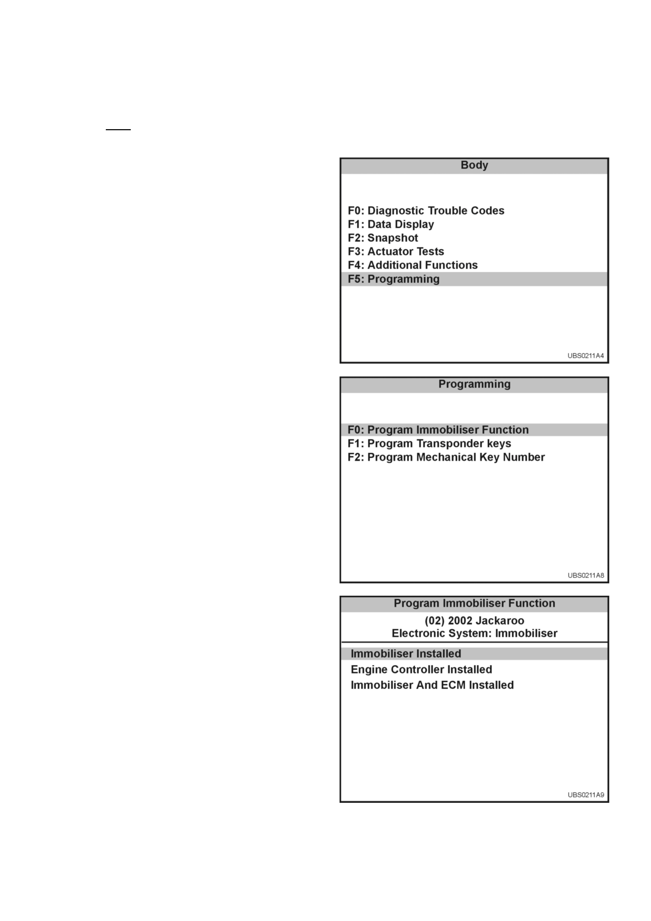
Programming The Immobiliser Control Unit (ICU)
TECH 2 will request the Vehicle Security Number during the program sequence - this must be obtained from
Holden TAS prior to commencing this operation.
Connect TECH 2 to the vehicle:
1. Select Diagnostics / MY2002 / Jackaroo / F2:
Body.
2. Select Immobiliser
3. Select F5: Programming.
4. Select F0: Program Immobiliser Function.
5. Select Immobiliser Installed
6. Obtain programming approval from TIS 2000.
7. Return to F0: Program Immobiliser Function.
8. When the SECURITY CODE is requested, enter
the security code and press ENTER.
9. When the VIN is requested, enter the vehicle
identification number and press ENTER.
10. When the MECHANICAL KEY number is
requested, enter the key number and press
ENTER.
11. Turn the ignition ON.
12. Select the engine type
13. Check the programming result
14. Program the transponder-keys to the ICU.
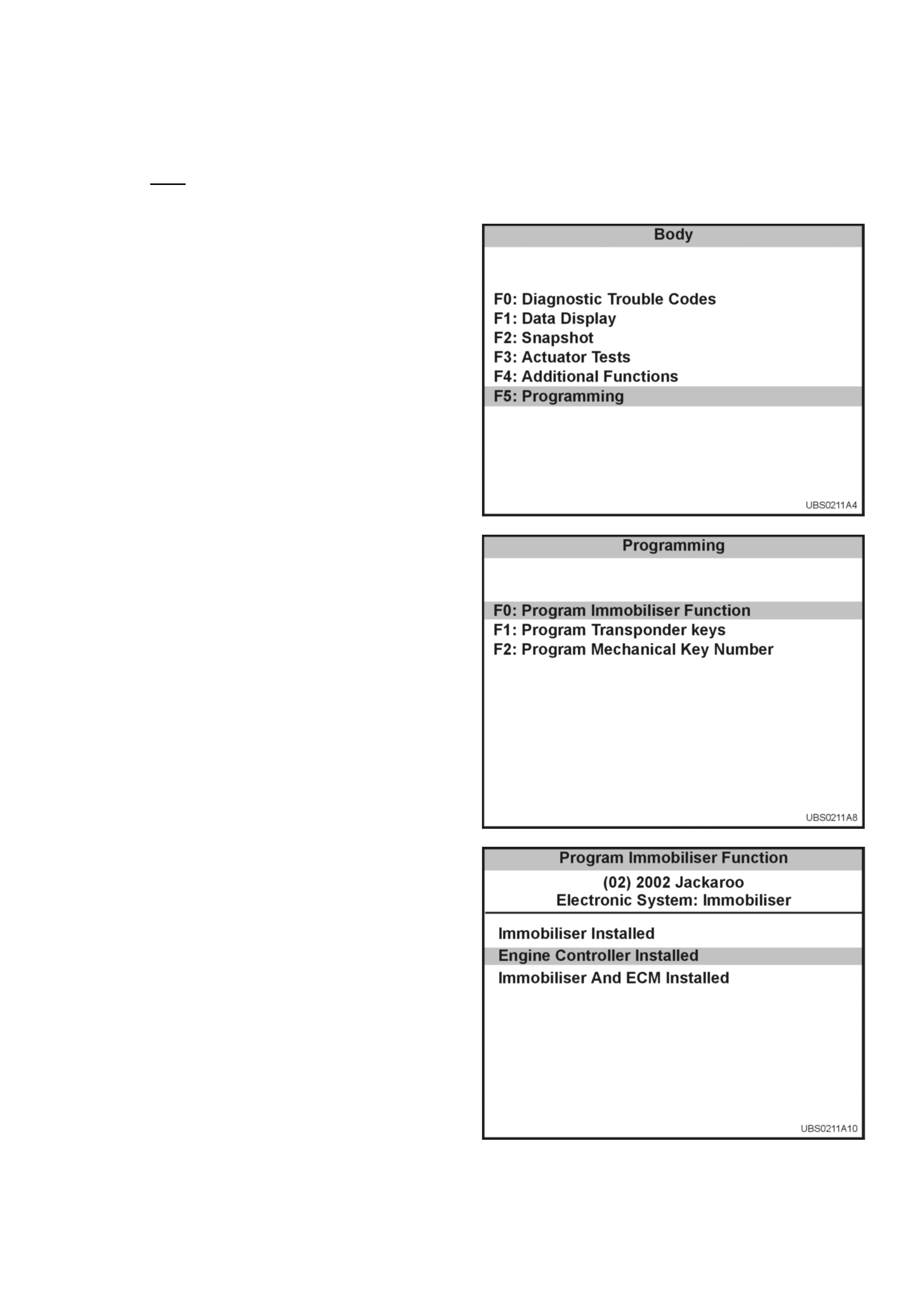
Programming The Engine Controller
TECH 2 will request the Vehicle Security Number during the program sequence - this must be obtained from
Holden TAS prior to commencing this operation.
Connect TECH 2 to the vehicle:
1. Select Diagnostics / MY2002 / Jackaroo / F2:
Body.
2. Select Immobiliser
3. Select F5: Programming.
4. Select F0: Program Immobiliser Function.
5. Select Engine Controller Installed
6. Obtain programming approval from TIS 2000.
7. Return to F0: Program Immobiliser Function.
8. When the SECURITY CODE is requested, enter
the security code and press ENTER.
9. When the VIN is requested, enter the vehicle
identification number and press ENTER.
10. When the MECHANICAL KEY number is
requested, enter the key number and press
ENTER.
11. Turn the ignition ON.
12. Select the engine type
13. Check the programming result
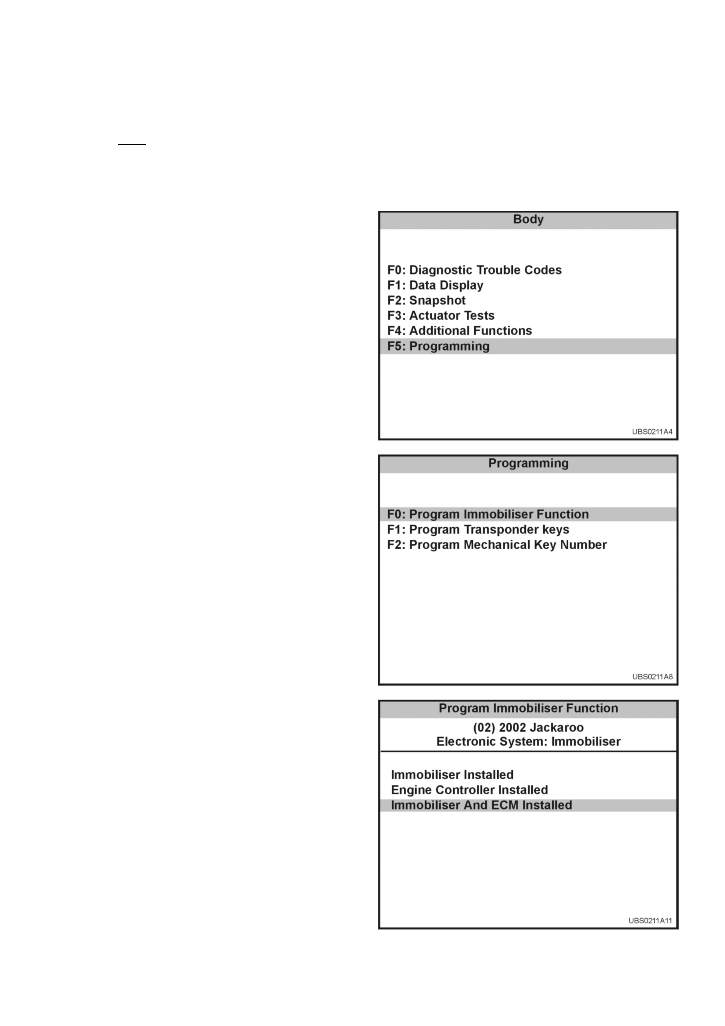
Programming The ICU And The PCM
TECH 2 will request the Vehicle Security Number during the program sequence - this must be obtained from
Holden TAS prior to commencing this operation.
When the DDS-1 and ICU are replaced at the same time, the ICU MUST be programmed BEFORE the
Immobiliser function of the DDS-1 can be activated.
Connect TECH-2 to the vehicle:
Connect TECH 2 to the vehicle:
1. Select Diagnostics / MY2002 / Jackaroo / F2:
Body.
2. Select Immobiliser
3. Select F5: Programming.
4. Select F0: Program Immobiliser Function.
5. Select Immobiliser and PCM Installed
6. Obtain programming approval from TIS 2000.
7. Return to F0: Program Immobiliser Function.
8. When the SECURITY CODE is requested, enter
the security code and press ENTER.
9. When the VIN is requested, enter the vehicle
identification number and press ENTER.
10. When the MECHANICAL KEY number is
requested, enter the key number and press
ENTER.
11. Turn the ignition ON.
12. Select the engine type
13. Check the programming result
14. Program the transponder-keys to the ICU.
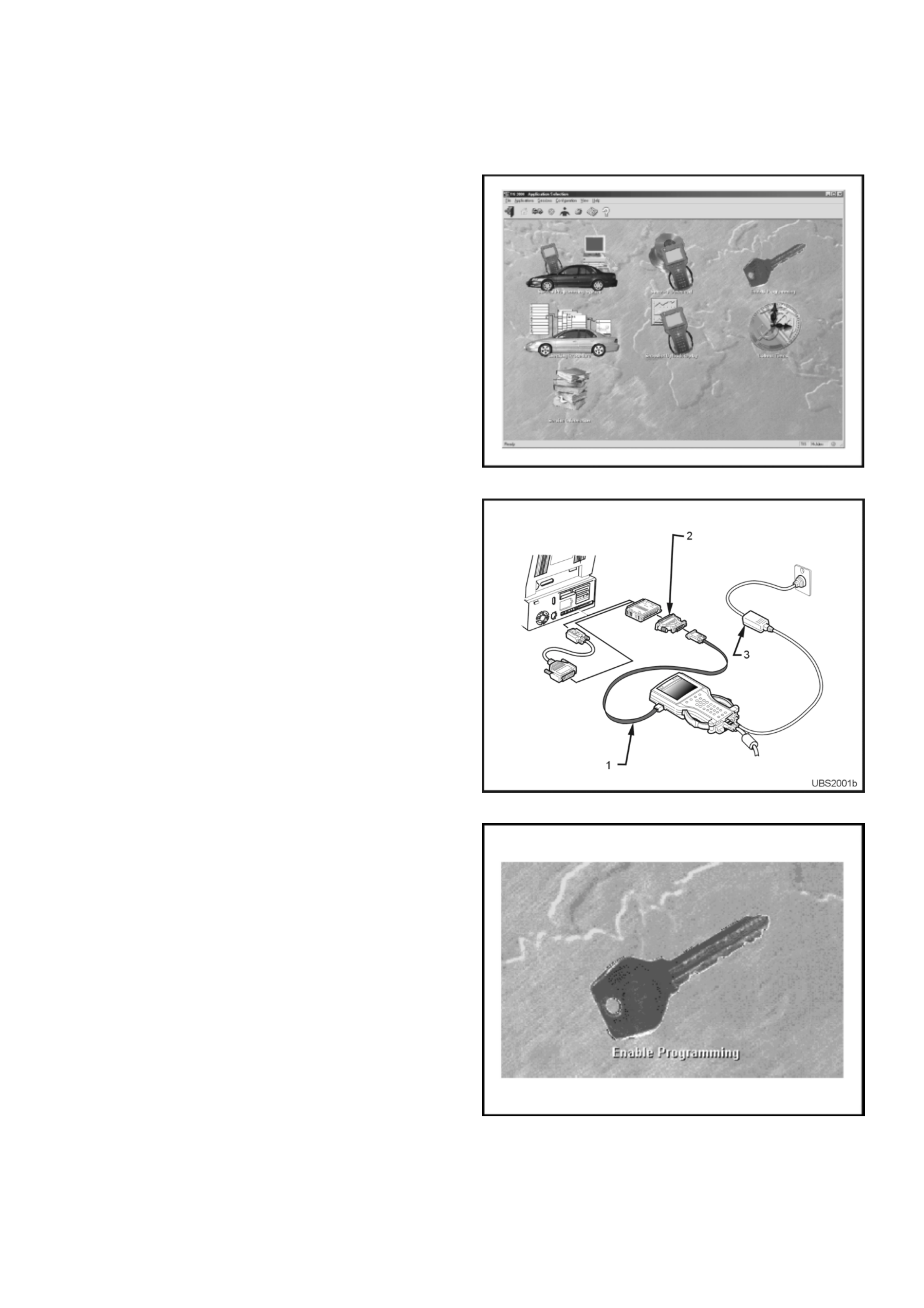
Enable Programming - TIS 2000
'Enable Programming' (TIS Approval) is used in order to
prevent the unauthorised programming of the system
security functions.
TIS Approval is required to perform the following
functions on the UBS Immobiliser System:
• Programming the Immobiliser Control Unit
• Programming the transponder keys
• Programming the PCM
After the TECH 2 security programming function has
been selected, TECH 2 will display - "Please get
programming approval from TIS'.
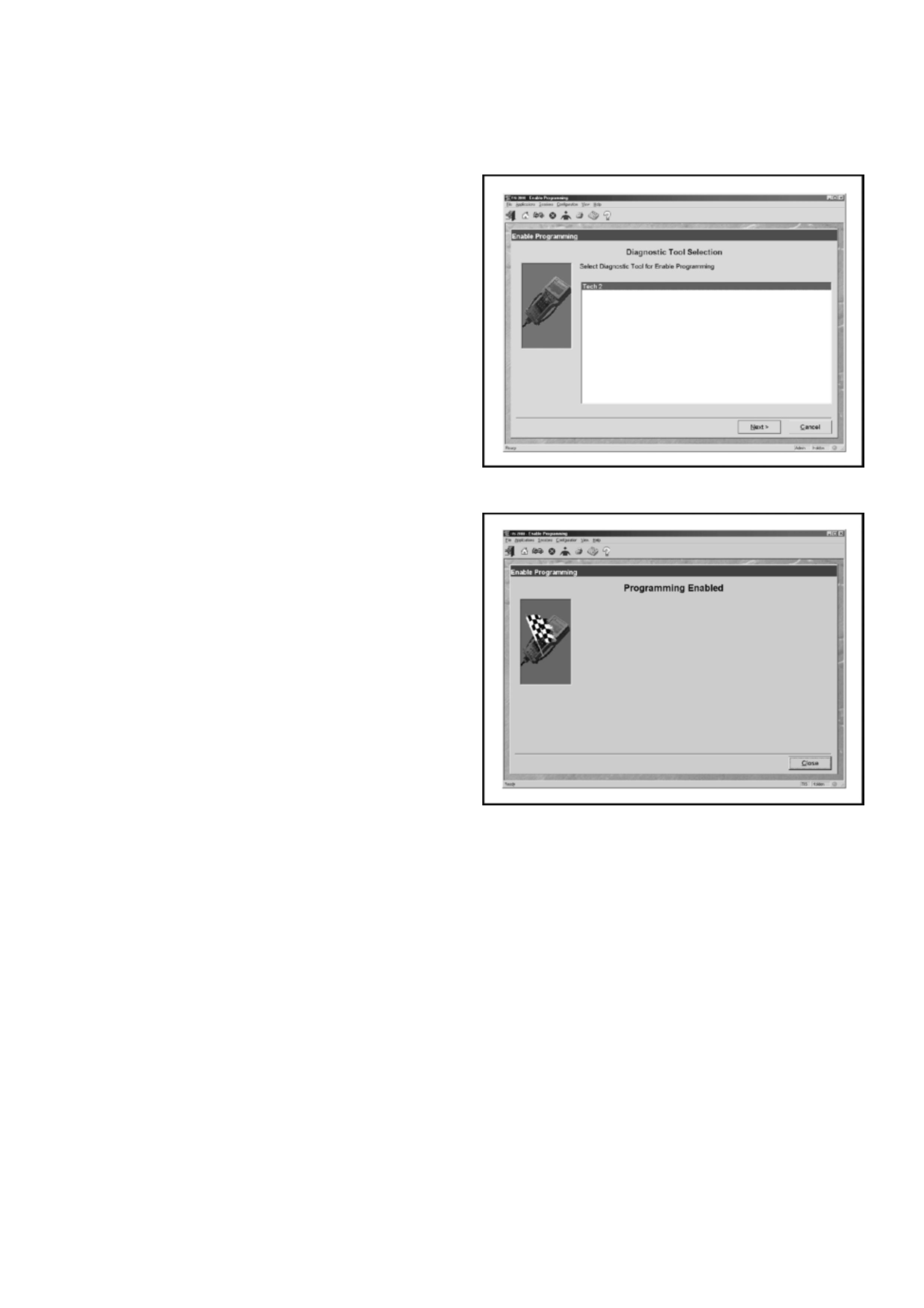
Enable Programming Procedure
1. Connect the RS232C interface cable (1) to the
TECH2 communication port.
2. Connect the other end of the RS232C cable to
the hardware key using the 9 pin and 25 pin
adaptors (2) .
3. Connect the hardware key to the serial port of
the TIS 2000 PC.
4. Connect the power supply (3) to the TECH 2
power jack.
5. Press the PWR button and allow TECH 2 to
boot to the start-up screen.
6. Click on the Enable Programming icon of the
TIS 2000 main screen.
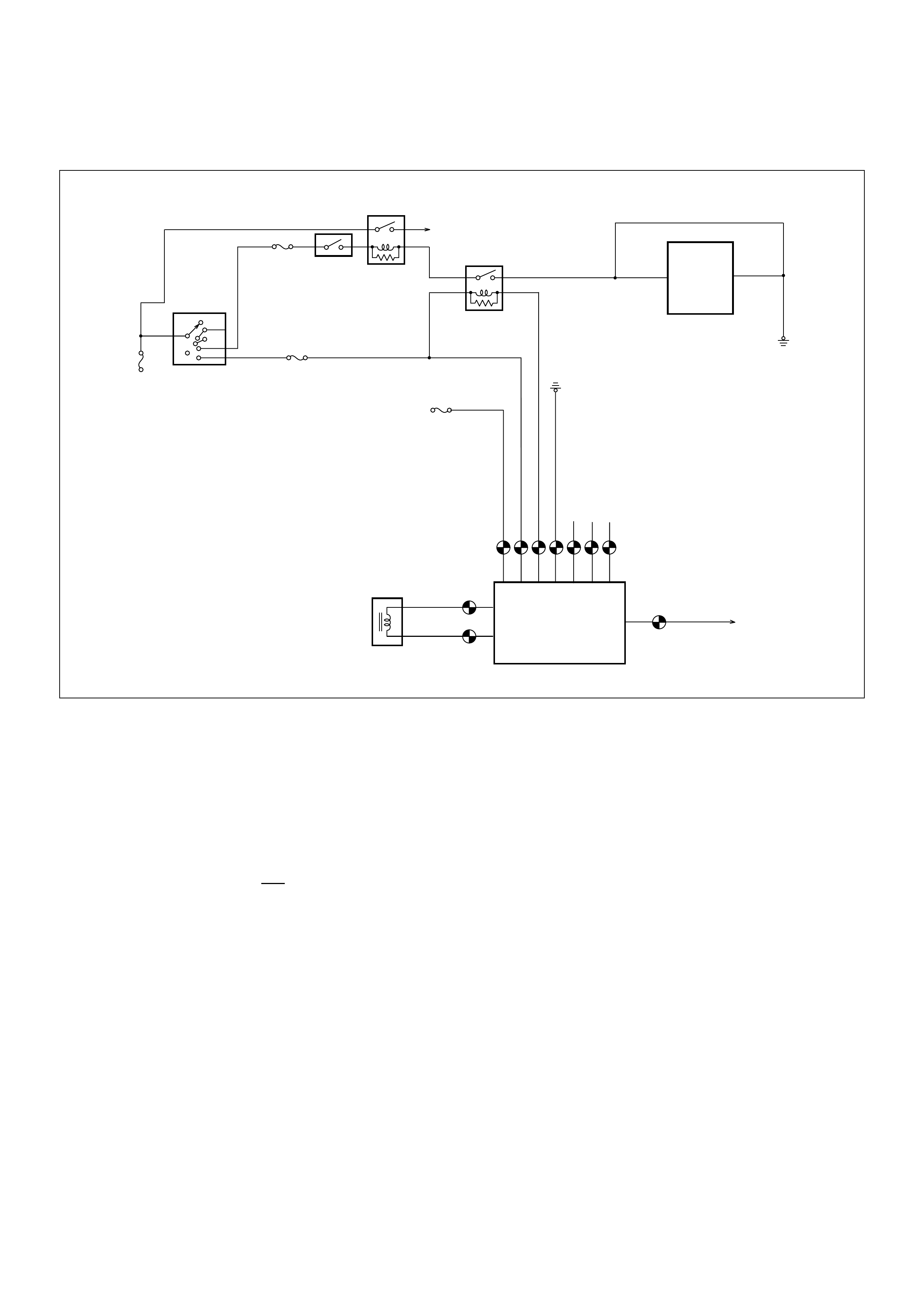
7. Select diagnostic tool (TECH 2) for Enable
Programming
8. Select Next to continue
9. When the process is completed, the
Programming Enabled screen will be displayed.
10. Click on the Close button to close the
application.
11. Reconnect TECH-2 to the vehicle DLC and
complete the programming function.

Diagnostic Trouble Codes
Current (Present) DTCs
The engine will not run when any current DTC is logged.
• The Powertrain Control Module disables the fuel and ignition systems.
• The ICU inhibits starter motor operation by disabling the Immobiliser relay.
History (Not Present) DTCs
When the fault has been repaired, the engine will operate normally and the current DTC becomes a History DTC.
These DTCs will normally clear on the next ignition cycle.
Multiple DTCs
If multiple DTCs are displayed on Tech 2, check integrity of power and ground circuits first, then use the following chart
to isolate the possible cause:
DTC ITEM
B8011 Transponder Key Problem
B8012 Wrong Transponder Key
B8013 Immobiliser Not Programmed
B8014 No Transponder key programmed
B8015 Vehicle Speed Signal Low
B8016 Vehicle Speed Signal High
B8017 No Engine Request Received
B8023 Antenna Coil Open Circuit
B8024 Wrong Transponder Response
B8025 Wrong Engine Request
B8026 Relay Output Low
B8027 Relay Output High
B8055 EEPROM Error
DTC Description
B8011 & B801 4 No Keys program m ed
B8011 , B8017 & B8023 Immobi liser Coil Circuit open
B8012 , B8013 & B8014 Immobi liser not progra mm ed
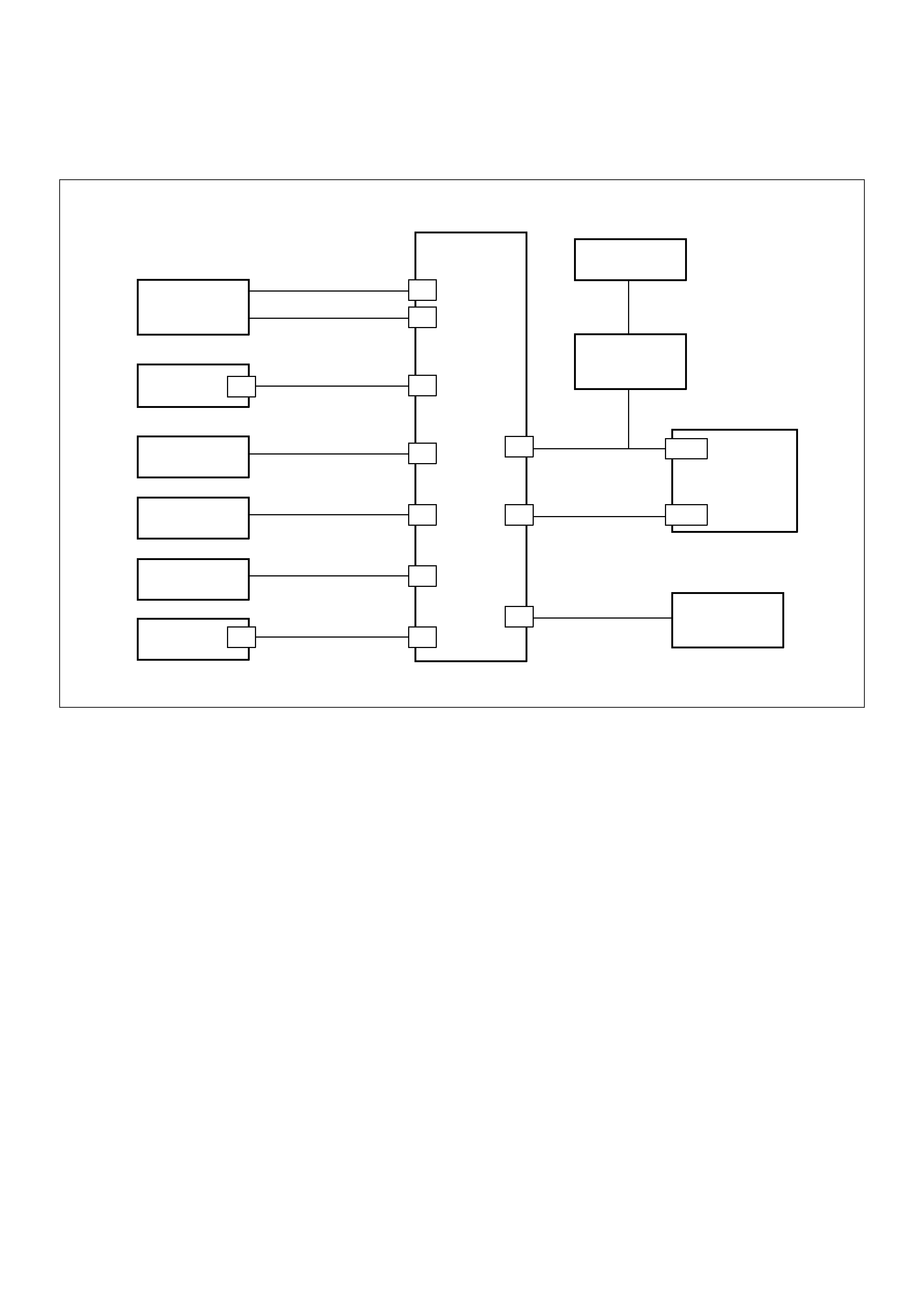
Engine Will Not Crank
No DTC Set
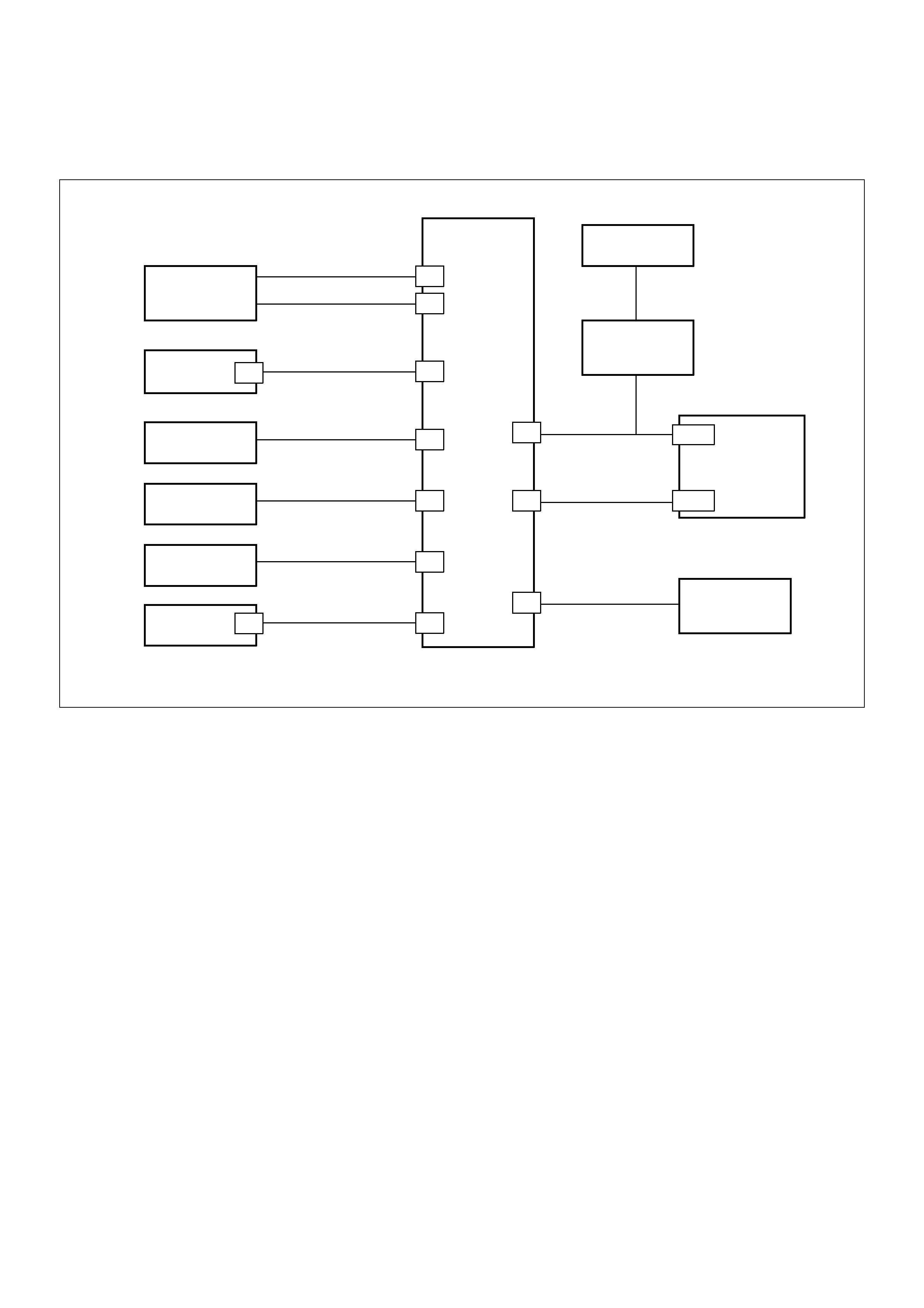
060RA00003
Circuit Description
The Immobiliser Control Unit provides the ground path
for the Immobiliser relay solenoid windings.
Note:
For Jackaroo SE & Monterey, the starter motor relay
windings ground through the Anti-theft Warning System
Control Module. On these vehicles, a no-crank condition
will occur due to failure in the Engine Immobiliser
System, starter motor circuit OR the Anti-theft Warning
Control Module.
Condition for Setting the DTC
Not Applicable
Action Taken When the DTC sets
Not Applicable
Condition for Clearing the CEL/DTC
Not Applicable
Diagnostic Aids
Check for the following conditions:
• Poor connection at PCM, Immobiliser Control Unit
and the Anti-theft Control Module. Inspect harness
connectors for backed out terminals, improper
mating, broken locks, improperly formed or damaged
terminals, and poor terminal to wire connection.
• If the harness appears to be OK, disconnect the PCM
and Immobiliser, turn the ignition “ON" and observe a
voltmeter connected to the suspect driver circuit at
the PCM and Immobiliser harness connector while
moving connectors and wiring harnesses relates to
the CEL. A change in voltage will indicate the location
of the fault.
ACC
B2
B1
OFF
IG2
ST
IG1
IGNITION
SWITCH
CLOCK (B)
10A
ENGINE
15A
0.5L 9
0.5Y D7
PCM
8
72
4
105
1
3
ANTENNA COIL
0.5G/Y
0.5B
0.5B/Y
0.5R/W
STARTER
10A
STARTER
MOTOR
IMMOBILISER
CONTROL
UNIT
IMMOBILISER
RELAY
STARTER
RELAY
MODE SW.
(AUTO)
6
ANTI-THEFT
CONTROL
UNIT
22 17
0.5W/B
W/O
ANTI-THEFT
KEY SW.
50A

Engine Will Not Crank - No DTC Set
Step Action Value(s) Yes No
1 Was the “On-Board Diagnostic (OBD) system Check"
performed ?
— Go to Step 2
Go to OBD
system check
Refer to Section
6D3
2 Check the PCM and ICU harne ss and connecto rs for :
1. Backed out terminals, improper mating, broken
locks, improperly formed or damaged terminals,
and poor ter min al to wire connection.
2. Damaged har ness - Inspect the wiring har ne ss for
damage.
If a problem found , repair as necessary.
Was a probl em found? Verify repair Go to Step 3
3 Turn the ignition ON, does the ‘CHECK ENGINE’
Lamp flas h at 2Hz? — Go to Step 4 Check star ter
motor circuit.
4 Wi th the ignition ON, check the voltage at ICU pin 5.
Is the voltage in specified range? 11.6v - 12.7v Go to Step 6 Go to Step 5
5 Check for continuity between 15A Engine Fuse & ICU
pin 5.
If a problem found , repair as necessary.
Was a probl em found? Verify repair Go to Step 6
6 Measure the resistance between ICU pin 4 and
ground.
Is the resistance less than the specified v alue? 5 9Go to Step 8 Go to Step 7
7 Repair the grou nd circuit from ICU pin 4 to ground
Is the action complete? — Verify repair —
8. Replace the ICU and the ex isting ignition keys
Reprogram the system Verify repair
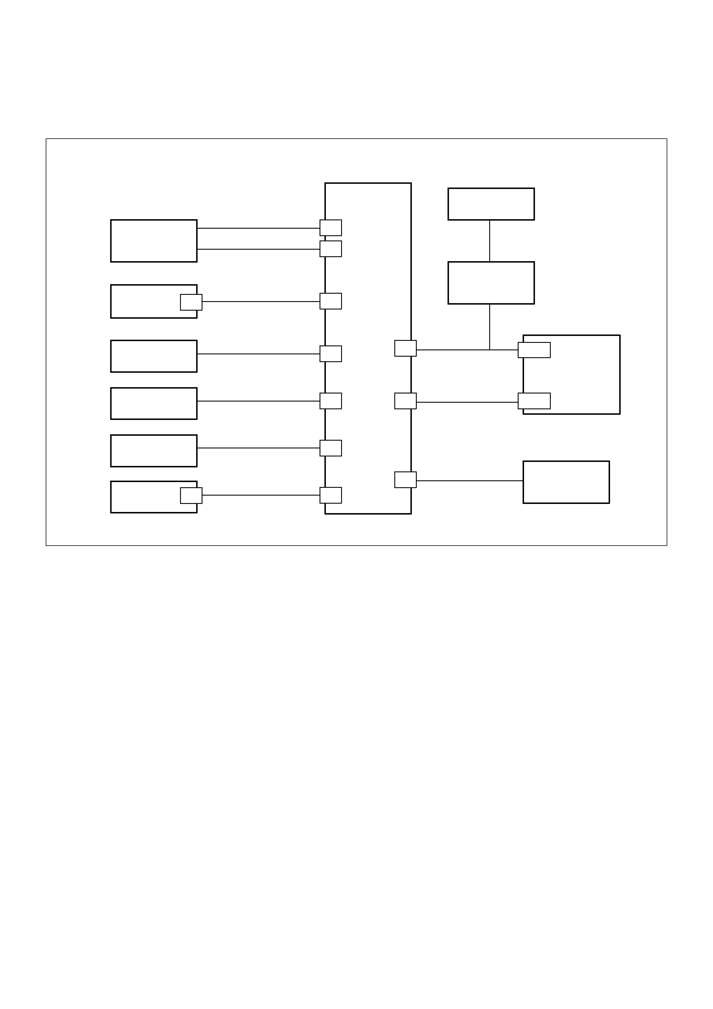
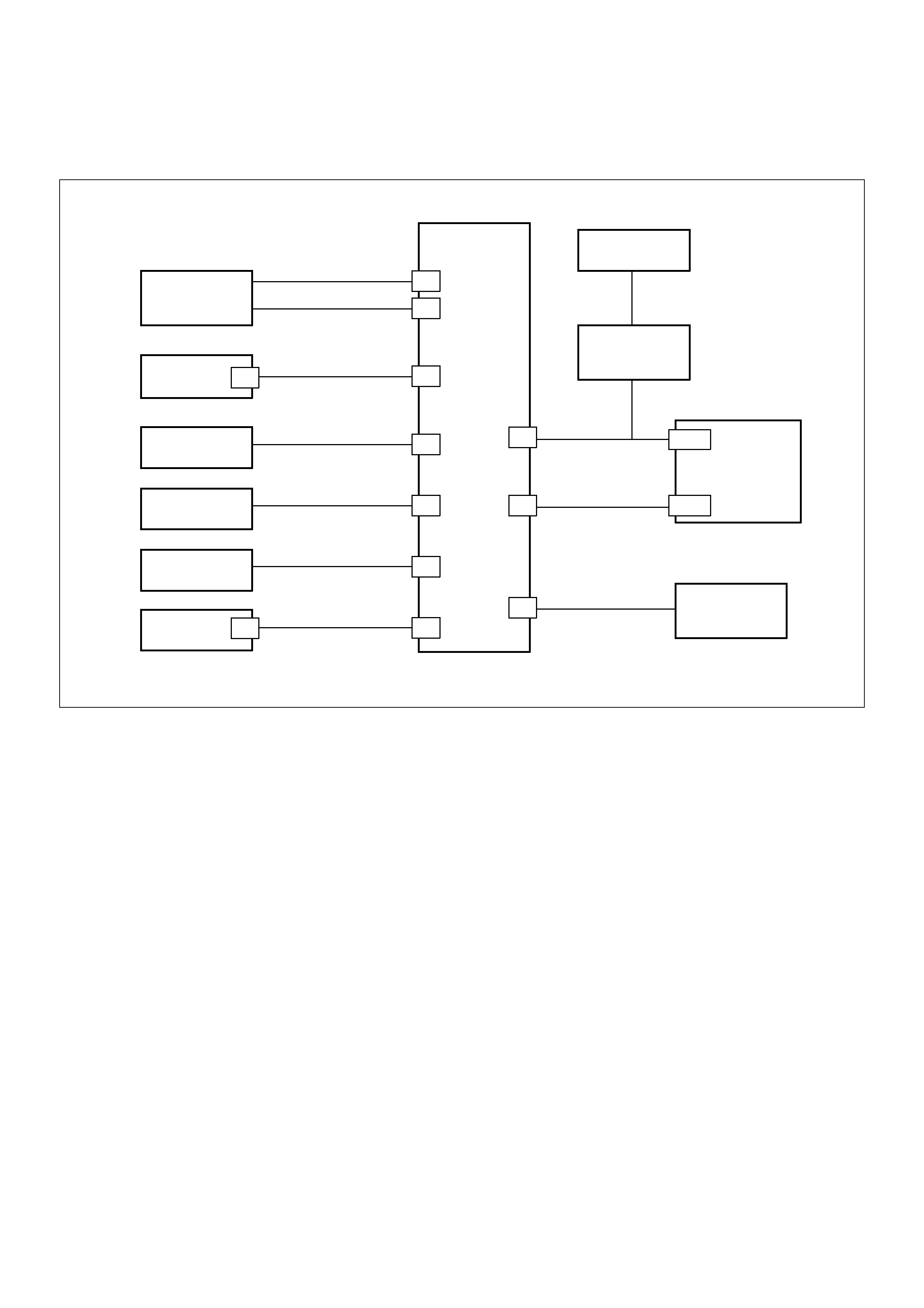
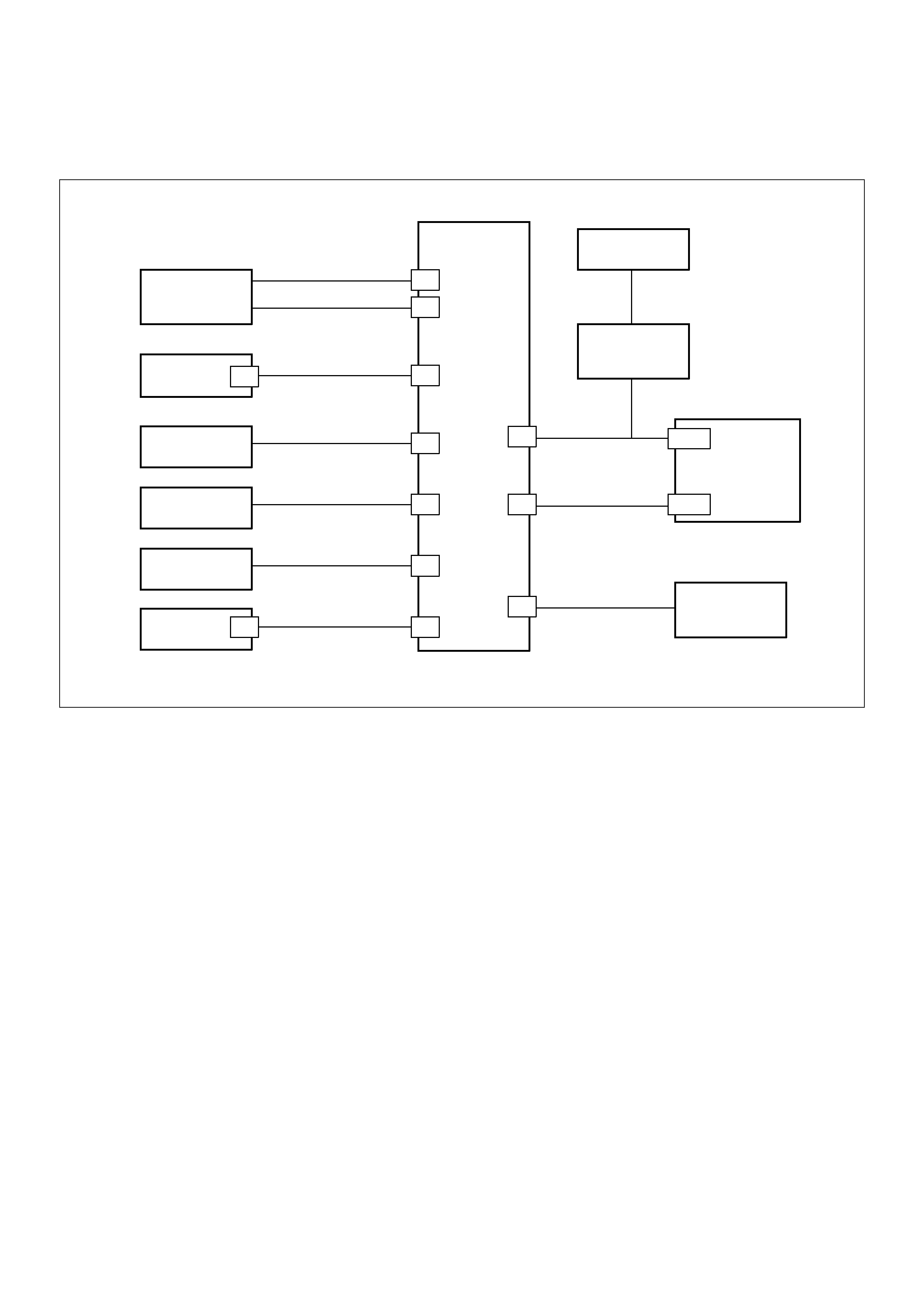
DTC B8011
Transponder Key Problem
060RA00003
Circuit Description
The Immobiliser Control Unit expects to receive a valid
transponder key signal when the ignition is turned ON.
Condition for Setting the DTC
A DTC B8011 will set if any of the following conditions
are present for at least 0.84 seconds during an
attempted start:
• No transponder-key signal is present
• The transponder-key is defective
• The key is not a transponder key
Action Taken When the DTC sets
• The engine will not crank
• The CHECK ENGINE Lamp will flash at 4Hz
Condition for Clearing the CEL/DTC
• Using TECH 2, select Clear DTC Information
• A History DTC B8011 will self-clear after 25
consecutive ignition cycles without the fault
recurring.
Diagnostic Aids
Check for the following conditions:
• Poor connection at PCM and Immobiliser Control
Unit. Inspect harness connectors for backed out
terminals, improper mating, broken locks, improperly
formed or damaged terminals, and poor terminal to
wire connection.
• Damaged harness-Inspect the wiring harness for
damage, If the harness appears to be OK, disconnect
the PCM and Immobiliser, turn the ignition “ON" and
observe a voltmeter connected to the suspect driver
circuit at the PCM and Immobiliser harness connector
while moving connectors and wiring harnesses
relates to the CEL. A change in voltage will indicate
the location of the fault.
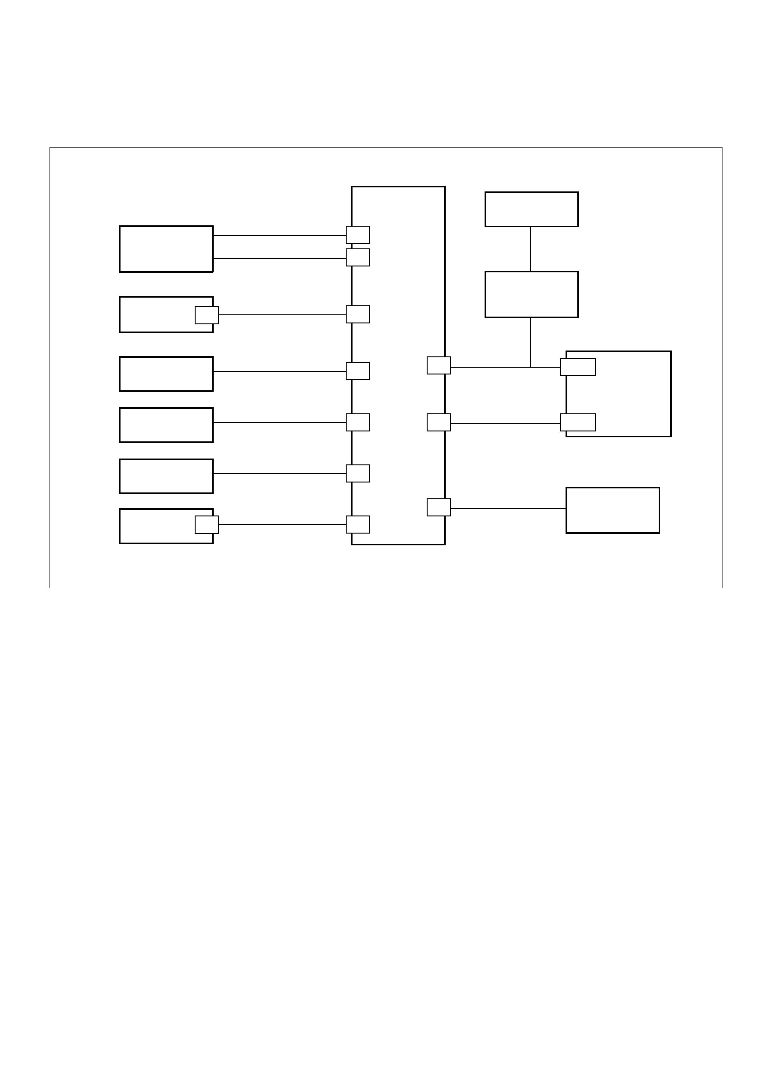
Immobiliser
Relay
Powertrain
Control
Module
Immobiliser
Control
Unit
Battery +ve
(Fuse C16)
Switched 12V
(Fuse C8)
Ground
Vehicle Speed
Signal
“Check Engine”
Lamp
DLC
DIAGNOSTIC
CONNECTION
DLC PIN 7
Antenna
Coil
0.5 YELLOW
0.5 RED/WHITE
0.5 GREEN/WHITE
0.85 RED/YELLOW
0.5 PURPLE
0.5 WHITE/BLACK
0.5 GREEN/YELLOW
0.5 BLUE
0.5 BLACK
0.5 ORANGE/BLACK
3
9
7
1
5
4
8
10
6
2A-13
D7
7
3
Ignition
Switch

DTC B811 - Transponder Key Problem
Step Action Value(s) Yes No
1 Was the “On-Board Diagnostic (OBD) system Check"
performed ?
— Go to Step 2
Go to OBD
system check
Refer to Section
6D3
2 Check the PCM and ICU harne ss and connecto rs for :
1. Backed out terminals, improper mating, broken
locks, improperly formed or damaged terminals,
and poor ter min al to wire connection.
2. Damaged har ness - Inspect the wiring har ne ss for
damage.
If a problem found , repair as necessary.
Was a probl em found? Verify repair Go to Step 3
3 Turn the ignition ON, does the ‘CHECK ENGINE’
Lamp flas h at 4Hz? — Go to Step 4 —
4 Check for correct operation with the other transponder
key/s
Does the system operate correctl y? — Go to Step 5 Go to Step 5
5 Reprogram the transponder key.
Was the programming succe ssful? Verify repair Go to Step 6
6 Is a DTC B8023 set after the p rogram attempt? Go to
Diagnost ic
Chart
DTC B8023 -
Antenna Coil
Circuit Go to Step 7
7 Replace the ICU and the existing ignition keys
Reprogram the system — Verify repair —

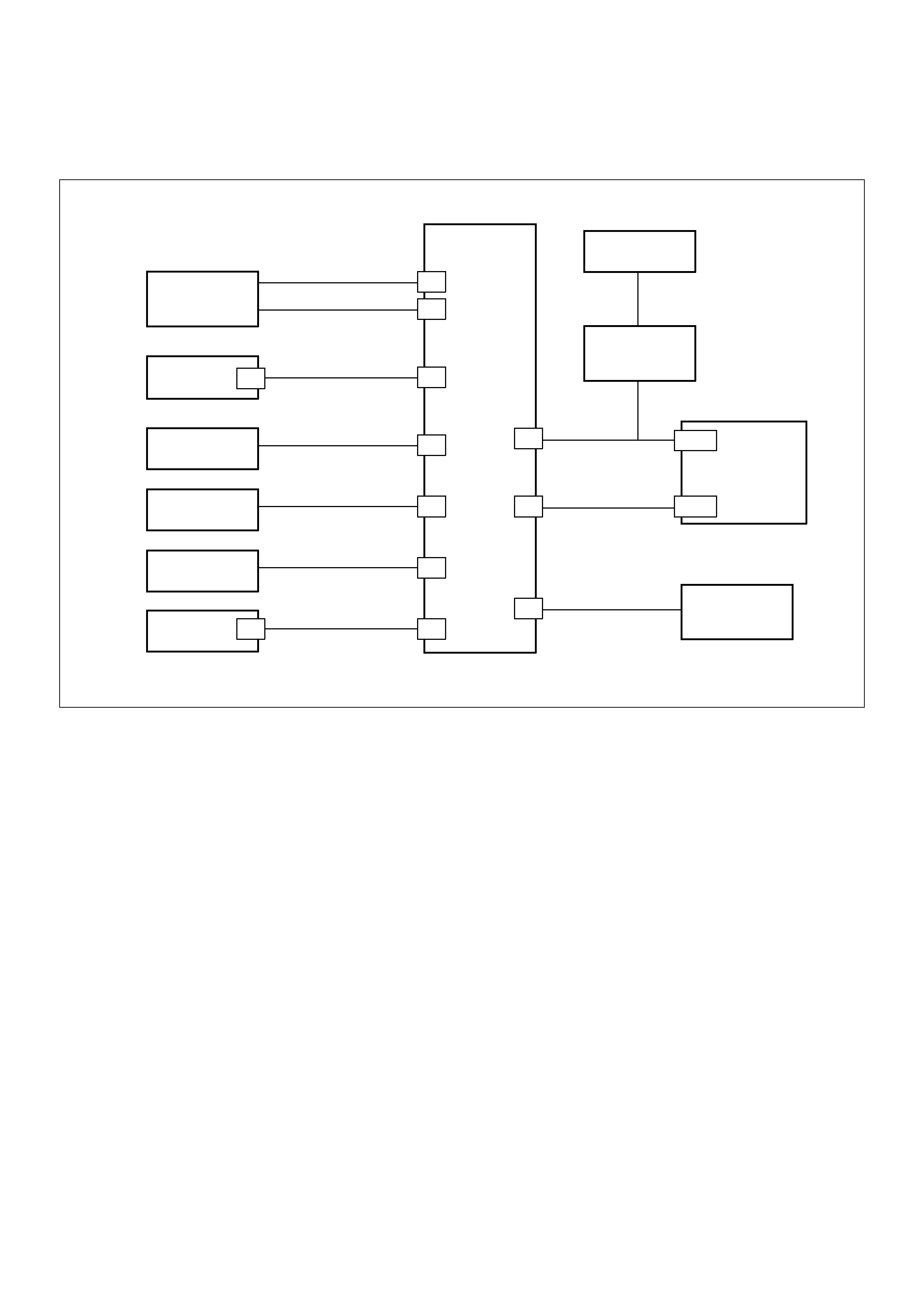
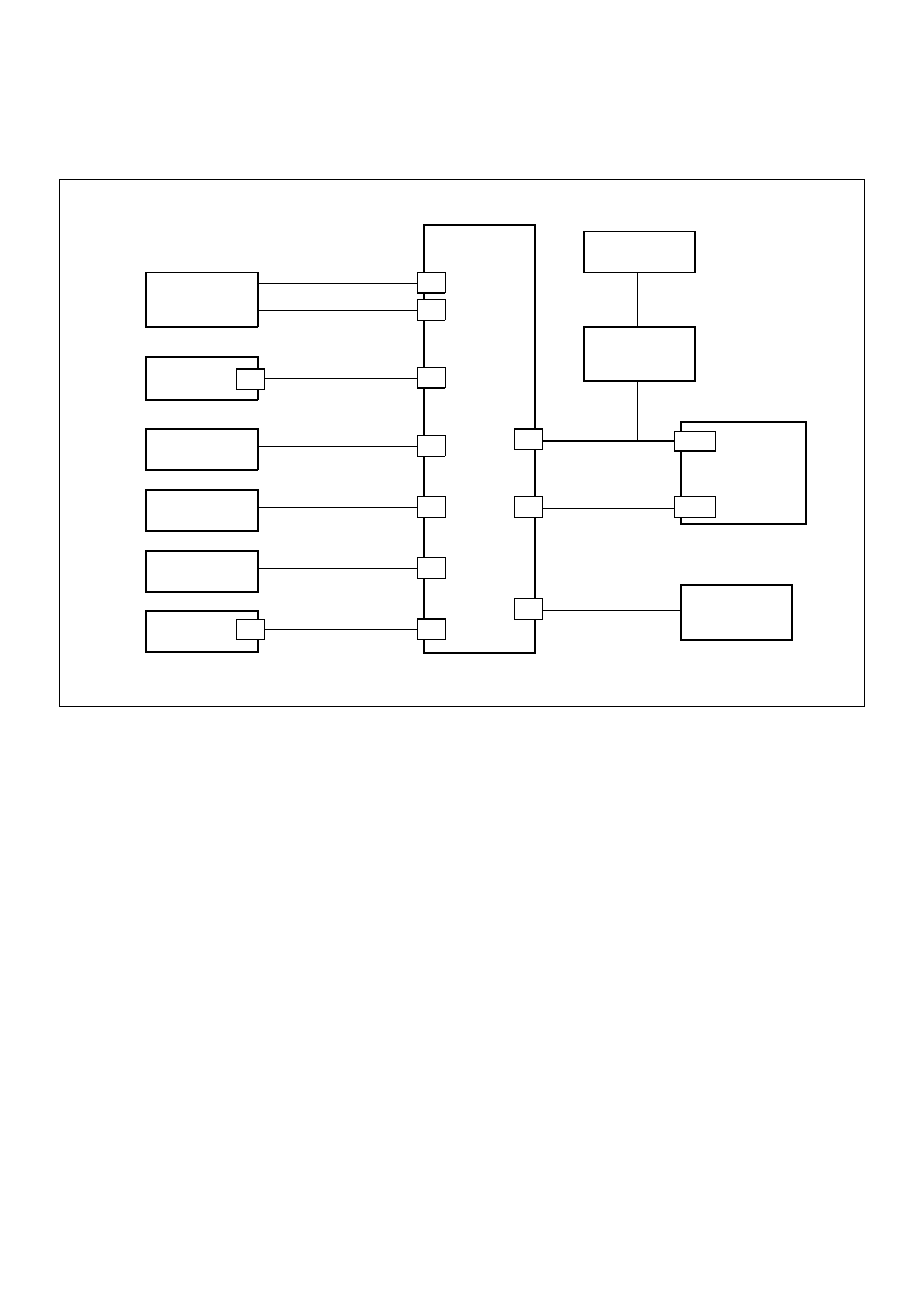
DTC B8012
Wrong Transponder Key
060RA00003
Circuit Description
The Immobiliser Control Unit expects to receive a valid
transponder key signal when the ignition is turned ON.
Condition for Setting the DTC
A DTC B8012 will set if any of the following conditions
are present for at least 0.84 seconds during an
attempted start:
• The transponder-key signal is not programmed to
the PCM
• The transponder read-out is interrupted
• The key is not a transponder key
Action Taken When the DTC sets
• The engine will not crank
• The CHECK ENGINE Lamp will flash at 4Hz
Condition for Clearing the CEL/DTC
• Using TECH 2, select Clear DTC Information
• A History DTC B8012 will self-clear after 25
consecutive ignition cycles without the fault
recurring.
Diagnostic Aids
Check for the following conditions:
• Poor connection at PCM and Immobiliser Control
Unit. Inspect harness connectors for backed out
terminals, improper mating, broken locks,
improperly formed or damaged terminals, and poor
terminal to wire connection.
• Damaged harness-Inspect the wiring harness for
damage, If the harness appears to be OK, disconnect
the PCM and Immobiliser, turn the ignition “ON" and
observe a voltmeter connected to the suspect driver
circuit at the PCM and Immobiliser harness connector
while moving connectors and wiring harnesses
relates to the CEL. A change in voltage will indicate
the location of the fault.
Immobiliser
Relay
Powertrain
Control
Module
Immobiliser
Control
Unit
Battery +ve
(Fuse C16)
Switched 12V
(Fuse C8)
Ground
Vehicle Speed
Signal
“Check Engine”
Lamp
DLC
DIAGNOSTIC
CONNECTION
DLC PIN 7
Antenna
Coil
0.5 YELLOW
0.5 RED/WHITE
0.5 GREEN/WHITE
0.85 RED/YELLOW
0.5 PURPLE
0.5 WHITE/BLACK
0.5 GREEN/YELLOW
0.5 BLUE
0.5 BLACK
0.5 ORANGE/BLACK
3
9
7
1
5
4
8
10
6
2A-13
D7
7
3
Ignition
Switch

DTC B8012 - Wrong Transponder Key
Step Action Value(s) Yes No
1 Check for correct operation with the other transponder
key/s
Does the system operate correctl y? — Go to Step 2 Go to Step 4
2 Reprogram the transponder key.
Was the programming succe ssful? Verify repair Go to Step 3
3 Replace the transponder key
Reprogram the system — Verify repair —
4 Replace the ICU and the existing ignition keys
Reprogram the system — Verify repair —
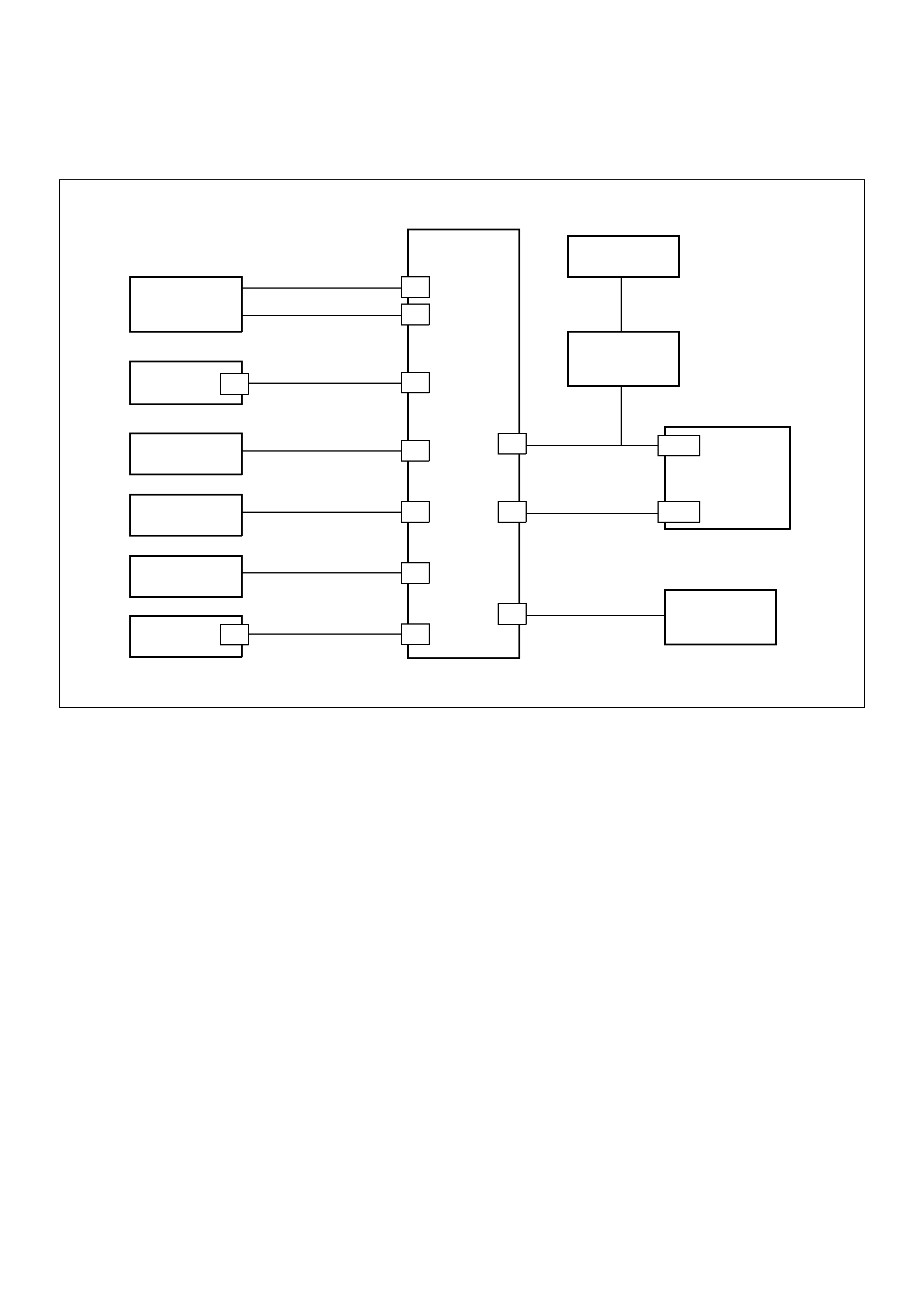
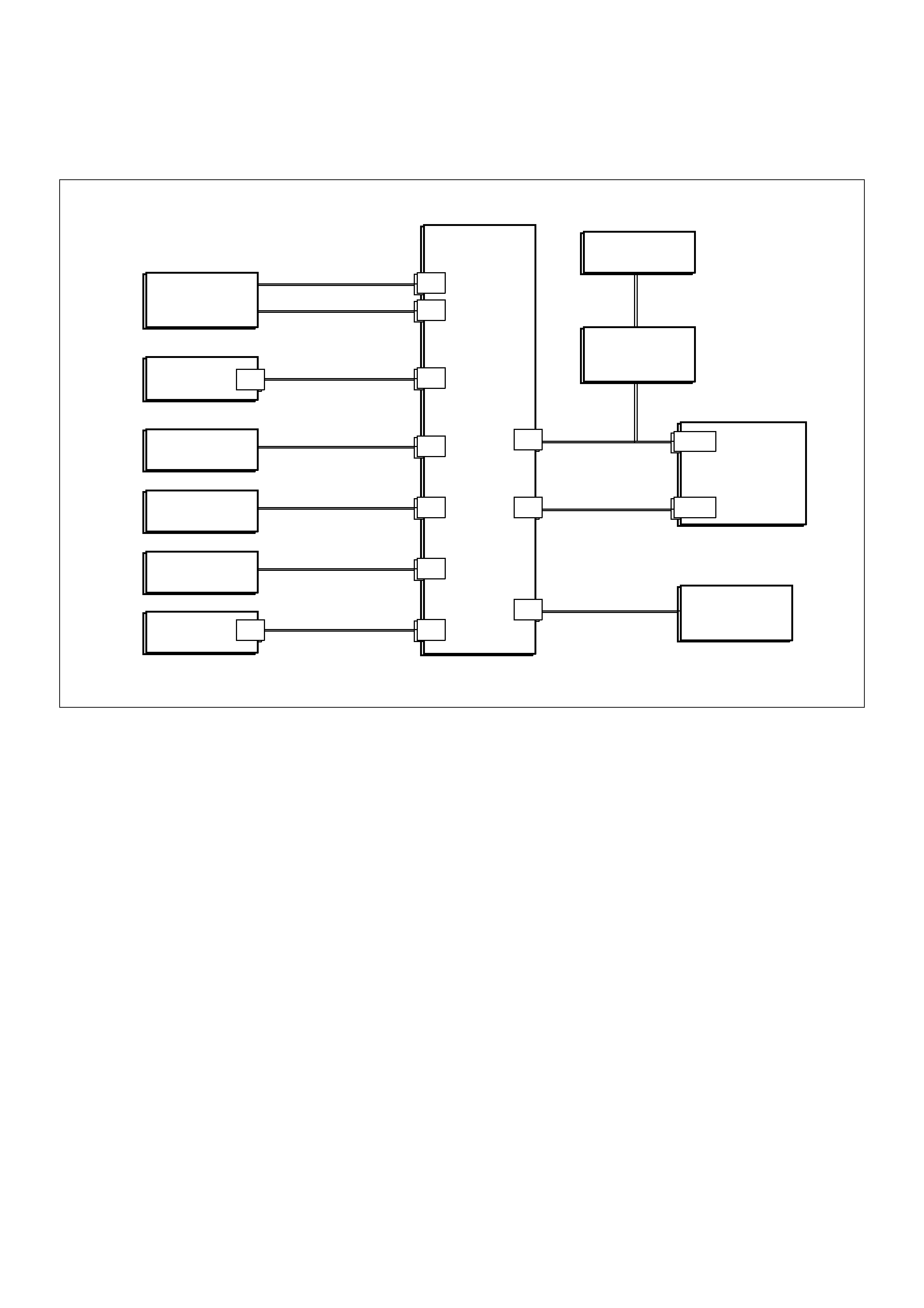
DTC B8013
Immobiliser Not Programmed
060RA00003
Circuit Description
The Immobiliser Control Unit expects to receive a valid
transponder key signal when the ignition is turned ON.
Condition for Setting the DTC
A DTC B8013 will set immendiately upon recognition If :
• The vehicle security code is not programmed into
the system.
Action Taken When the DTC sets
• The engine will not crank
• The CHECK ENGINE Lamp will flash at 4Hz
Condition for Clearing the CEL/DTC
• Using TECH 2, select Clear DTC Information
• A History DTC B8013 will self-clear after 25
consecutive ignition cycles without the fault
recurring.
Diagnostic Aids
Check for the following conditions:
• Poor connection at PCM and Immobiliser Control
Unit. Inspect harness connectors for backed out
terminals, improper mating, broken locks, improperly
formed or damaged terminals, and poor terminal to
wire connection.
• Damaged harness-Inspect the wiring harness for
damage, If the harness appears to be OK, disconnect
the PCM and Immobiliser, turn the ignition “ON" and
observe a voltmeter connected to the suspect driver
circuit at the PCM and Immobiliser harness connector
while moving connectors and wiring harnesses
relates to the CEL. A change in voltage will indicate
the location of the fault.
Immobiliser
Relay
Powertrain
Control
Module
Immobiliser
Control
Unit
Battery +ve
(Fuse C16)
Switched 12V
(Fuse C8)
Ground
Vehicle Speed
Signal
“Check Engine”
Lamp
DLC
DIAGNOSTIC
CONNECTION
DLC PIN 7
Antenna
Coil
0.5 YELLOW
0.5 RED/WHITE
0.5 GREEN/WHITE
0.85 RED/YELLOW
0.5 PURPLE
0.5 WHITE/BLACK
0.5 GREEN/YELLOW
0.5 BLUE
0.5 BLACK
0.5 ORANGE/BLACK
3
9
7
1
5
4
8
10
6
2A-13
D7
7
3
Ignition
Switch

DTC B8013 - Immobiliser Not Programmed
Step Action Value(s) Yes No
1 Attempt to reprogram the security information
Was the programming successful? — Verify repair Go to Step 2
2 Was the “On-Board Diagnostic (OBD) system Check"
performed ?
— Go to Step 3
Go to OBD
system check
Refer to Section
6D3
3 Check the PCM and ICU harne ss and connecto rs for :
1. Backed out terminals, improper mating, broken
locks, improperly formed or damaged terminals,
and poor ter min al to wire connection.
2. Damaged har ness - Inspect the wiring har ne ss for
damage.
If a problem found , repair as necessary.
Was a problem found? — Verify repair G o to Step 4
4 Replace the ICU and the existing ignition keys
Reprogram the system — Verify repair —
DTC B8014
No Transponder Key Programmed
060RA00003
Circuit Description
The Immobiliser Control Unit expects to receive a valid
transponder key signal when the ignition is turned ON.
Condition for Setting the DTC
A DTC B8014 will set immendiately upon recognition If :
• No transponder keys are programmed into the
system.
Action Taken When the DTC sets
• The engine will not crank
• The CHECK ENGINE Lamp will flash at 4Hz
Condition for Clearing the CEL/DTC
• Using TECH 2, select Clear DTC Information
• A History DTC B8014 will self-clear after 25
consecutive ignition cycles without the fault
recurring.
Diagnostic Aids
Check for the following conditions:
• Poor connection at PCM and Immobiliser Control
Unit. Inspect harness connectors for backed out
terminals, improper mating, broken locks, improperly
formed or damaged terminals, and poor terminal to
wire connection.
• Damaged harness-Inspect the wiring harness for
damage, If the harness appears to be OK, disconnect
the PCM and Immobiliser, turn the ignition “ON" and
observe a voltmeter connected to the suspect driver
circuit at the PCM and Immobiliser harness connector
while moving connectors and wiring harnesses
relates to the CEL. A change in voltage will indicate
the location of the fault.
Immobiliser
Relay
Powertrain
Control
Module
Immobiliser
Control
Unit
Battery +ve
(Fuse C16)
Switched 12V
(Fuse C8)
Ground
Vehicle Speed
Signal
“Check Engine”
Lamp
DLC
DIAGNOSTIC
CONNECTION
DLC PIN 7
Antenna
Coil
0.5 YELLOW
0.5 RED/WHITE
0.5 GREEN/WHITE
0.85 RED/YELLOW
0.5 PURPLE
0.5 WHITE/BLACK
0.5 GREEN/YELLOW
0.5 BLUE
0.5 BLACK
0.5 ORANGE/BLACK
3
9
7
1
5
4
8
10
6
2A-13
D7
7
3
Ignition
Switch

DTC B8014 - No Transponder Key Programmed
Step Action Value(s) Yes No
1 Attempt to reprogram the transponder keys
Was the programming successful? — Verify repair Go to Step 2
2 Was the “On-Board Diagnostic (OBD) system Check"
performed ?
— Go to Step 3
Go to OBD
system check
Refer to Section
6D3
3 Check the PCM and ICU harne ss and connecto rs for :
1. Backed out terminals, improper mating, broken
locks, improperly formed or damaged terminals,
and poor ter min al to wire connection.
2. Damaged har ness - Inspect the wiring har ne ss for
damage.
If a problem found , repair as necessary.
Was a problem found? — Verify repair G o to Step 4
4 Replace the ICU and the existing ignition keys
Reprogram the system — Verify repair —
DTC B8015
Vehicle Speed Sensor Signal Low (<2.5v)
060RA00003
Circuit Description
Immediately the ignition is turned ‘ON’, the Immobiliser
Control Unit communicates the transponder key signal
to the PCM via the Vehicle Speed Sensor signal input
circuit. After a period of approximately 0.84 sec., the
ICU will cease transmission and the circuit will switch to
allow the PCM to receive the Vehicle Speed Sensor
input signal.
Condition for Setting the DTC
A DTC B8015 will set immediately upon recognition If :
• The voltage on the circuit between ICU pin 6 and
PCM pin D7 is less than 2.5 volts for more than
0.5 secs. after the ignition is switched ‘ON’
Action Taken When the DTC sets
• The engine will not crank
• The CHECK ENGINE Lamp will flash at 4Hz
Condition for Clearing the CEL/DTC
• Using TECH 2, select Clear DTC Information
• A History DTC B8015 will self-clear after 25
consecutive ignition cycles without the fault
recurring.
Diagnostic Aids
Check for the following conditions:
• Poor connection at PCM and Immobiliser Control
Unit. Inspect harness connectors for backed out
terminals, improper mating, broken locks, improperly
formed or damaged terminals, and poor terminal to
wire connection.
• Damaged harness-Inspect the wiring harness for
damage, If the harness appears to be OK, disconnect
the PCM and Immobiliser, turn the ignition “ON" and
observe a voltmeter connected to the suspect driver
circuit at the PCM and Immobiliser harness connector
while moving connectors and wiring harnesses
relates to the CEL. A change in voltage will indicate
the location of the fault.
Immobiliser
Relay
Powertrain
Control
Module
Immobiliser
Control
Unit
Battery +ve
(Fuse C16)
Switched 12V
(Fuse C8)
Ground
Vehicle Speed
Signal
“Check Engine”
Lamp
DLC
DIAGNOSTIC
CONNECTION
DLC PIN 7
Antenna
Coil
0.5 YELLOW
0.5 RED/WHITE
0.5 GREEN/WHITE
0.85 RED/YELLOW
0.5 PURPLE
0.5 WHITE/BLACK
0.5 GREEN/YELLOW
0.5 BLUE
0.5 BLACK
0.5 ORANGE/BLACK
3
9
7
1
5
4
8
10
6
2 A-13
D7
7
3
Ignition
Switch

DTC B8015 - Vehicle Speed Sensor Signal Low (<2.5v.)
Step Action Value(s) Yes No
1Was the “On-Board Diagnostic (OBD) system Check"
performed?
— Go to Step 2
Go to OBD
system check
Refer to Section
6D3
2 Check for continuity between ICU harness connector
pin 6 and PCM pin D7.
If a problem was found, repair as necessary.
Was a problem found? — Go to Step 4 Go to Step 3
3 • Disconnect the PCM harness connectors.
• Check for continuity between ICU harness
connector pin 6 and ground.
If a problem was found, repair as necessary.
Was a problem found? — Go to Step 4 Go to Step 4
4 Clear the DTC and start the engine.
Does the DTC reset? — Go to Step 2 —

DTC B8016
Vehicle Speed Sensor Signal High (>2.5v)
060RA00003
Circuit Description
Immediately the ignition is turned ‘ON’, the Immobiliser
Control Unit communicates the transponder key signal
to the PCM via the Vehicle Speed Sensor signal input
circuit. After a period of approximately 0.84 sec., the
ICU will cease transmission and the circuit will switch to
allow the PCM to receive the Vehicle Speed Sensor
input signal.
Condition for Setting the DTC
A DTC B8016 will set immediately upon recognition If :
• The voltage on the circuit between ICU pin 6 and
PCM pin D7 is greater than 2.5 volts for longer
than 0.5 secs. after the ignition is switched ‘ON’
Action Taken When the DTC sets
• The engine will not crank
• The CHECK ENGINE Lamp will flash at 4Hz
Condition for Clearing the CEL/DTC
• Using TECH 2, select Clear DTC Information
• A History DTC B8016 will self-clear after 25
consecutive ignition cycles without the fault
recurring.
Diagnostic Aids
Check for the following conditions:
• Poor connection at PCM and Immobiliser Control
Unit. Inspect harness connectors for backed out
terminals, improper mating, broken locks, improperly
formed or damaged terminals, and poor terminal to
wire connection.
• Damaged harness-Inspect the wiring harness for
damage, If the harness appears to be OK, disconnect
the PCM and Immobiliser, turn the ignition “ON" and
observe a voltmeter connected to the suspect driver
circuit at the PCM and Immobiliser harness connector
while moving connectors and wiring harnesses
relates to the CEL. A change in voltage will indicate
the location of the fault.
Immobiliser
Relay
Powertrain
Control
Module
Immobiliser
Control
Unit
Battery +ve
(Fuse C16)
Switched 12V
(Fuse C8)
Ground
Vehicle Speed
Signal
“Check Engine”
Lamp
DLC
DIAGNOSTIC
CONNECTION
DLC PIN 7
Antenna
Coil
0.5 YELLOW
0.5 RED/WHITE
0.5 GREEN/WHITE
0.85 RED/YELLOW
0.5 PURPLE
0.5 WHITE/BLACK
0.5 GREEN/YELLOW
0.5 BLUE
0.5 BLACK
0.5 ORANGE/BLACK
3
9
7
1
5
4
8
10
6
2 A-13
D7
7
3
Ignition
Switch

DTC B8016 - Vehicle Speed Sensor Signal High (>2.5v)
Step Action Value(s) Yes No
1Was the “On-Board Diagnostic (OBD) system Check"
performed?
— Go to Step 2
Go to OBD
system check
Refer to Section
6D3
2 • Turn the ignition ON.
• Measure the voltage at ICU pin 6.
Is the voltage greater than 2.5 volts? — Go to Step 3 Go to Step 4
3 • Disconnect the PCM harness connectors.
• Check for continuity between ICU harness
connector pin 6 and power.
If power was found, repair the circuit as necessary.
Was a problem found? — Verify repair Go to Step 4
4 Clear the DTC and start the engine.
Does the DTC reset? — Go to Step 2 —
DTC B8017
No PCM Request Received
060RA00003
Circuit Description
The PCM transmits an ‘PCM Request’ signal to the ICU
when the ignition is turned ON.
Condition for Setting the DTC
A DTC B8017 will set if, after 0.5 secs. of turning the
ignition ON:
• The ICU does not receive an ‘PCM Request’
signal from the PCM.
Action Taken When the DTC sets
• The engine will not crank
• The CHECK ENGINE Lamp will flash at 4Hz
Condition for Clearing the CEL/DTC
• Using TECH 2, select Clear DTC Information
• A History DTC B8017 will self-clear after 25
consecutive ignition cycles without the fault
recurring.
Diagnostic Aids
Check for the following conditions:
• Poor connection at PCM and Immobiliser Control
Unit. Inspect harness connectors for backed out
terminals, improper mating, broken locks, improperly
formed or damaged terminals, and poor terminal to
wire connection.
• Damaged harness-Inspect the wiring harness for
damage, If the harness appears to be OK, disconnect
the PCM and Immobiliser, turn the ignition “ON" and
observe a voltmeter connected to the suspect driver
circuit at the PCM and Immobiliser harness connector
while moving connectors and wiring harnesses
relates to the CEL. A change in voltage will indicate
the location of the fault.
Immobiliser
Relay
Powertrain
Control
Module
Immobiliser
Control
Unit
Battery +ve
(Fuse C16)
Switched 12V
(Fuse C8)
Ground
Vehicle Speed
Signal
“Check Engine”
Lamp
DLC
DIAGNOSTIC
CONNECTION
DLC PIN 7
Antenna
Coil
0.5 YELLOW
0.5 RED/WHITE
0.5 GREEN/WHITE
0.85 RED/YELLOW
0.5 PURPLE
0.5 WHITE/BLACK
0.5 GREEN/YELLOW
0.5 BLUE
0.5 BLACK
0.5 ORANGE/BLACK
3
9
7
1
5
4
8
10
6
2A-13
D7
7
3
Ignition
Switch

DTC B8017 - No PCM Request Received
Step Action Value(s) Yes No
1 Was the “On-Board Diagnostic (OBD) system Check"
performed ?
— Go to Step 2
Go to OBD
system check
Refer to Section
6D3
2 Check for an open circuit between ICU pin 2 and PCM
pin A13.
If a problem found , repair as necessary.
Was a probl em found? — Verify repair Go to Step 3
3 1. Disconnect the PC M connect or.
2. Check for continuity between ICU pin 2 and
ground
If a continuity is found, rep air as necessary.
Was continuity found? — Verify repair Go to Step 4
4 Repl ace the PCM (Inter nal circuit fail ure).
Important: The PCM and ICU must be link ed, r efer to
this Section f or the correct procedure.
Is the action complete? — Verify repair —
DTC B8023
Antenna Coil Open Circuit
060RA00003
Circuit Description
The Immobiliser Control Unit expects to receive a valid
transponder key signal when the ignition is turned ON.
The ICU and transponder key communicate via the
antenna coil circuit.
Condition for Setting the DTC
A DTC B8023 will set immendiately upon recognition If :
• The antenna coil is not connected or there is an
open in the antenna coil circuit.
Action Taken When the DTC sets
• The engine will not crank
• The CHECK ENGINE Lamp will flash at 4Hz
Condition for Clearing the CEL/DTC
• Using TECH 2, select Clear DTC Information
• A History DTC B8023 will self-clear after 25
consecutive ignition cycles without the fault
recurring.
Diagnostic Aids
Check for the following conditions:
• Poor connection at PCM and Immobiliser Control
Unit. Inspect harness connectors for backed out
terminals, improper mating, broken locks, improperly
formed or damaged terminals, and poor terminal to
wire connection.
• Damaged harness-Inspect the wiring harness for
damage, If the harness appears to be OK, disconnect
the PCM and Immobiliser, turn the ignition “ON" and
observe a voltmeter connected to the suspect driver
circuit at the PCM and Immobiliser harness connector
while moving connectors and wiring harnesses
relates to the CEL. A change in voltage will indicate
the location of the fault.
Immobiliser
Relay
Powertrain
Control
Module
Immobiliser
Control
Unit
Battery +ve
(Fuse C16)
Switched 12V
(Fuse C8)
Ground
Vehicle Speed
Signal
“Check Engine”
Lamp
DLC
DIAGNOSTIC
CONNECTION
DLC PIN 7
Antenna
Coil
0.5 YELLOW
0.5 RED/WHITE
0.5 GREEN/WHITE
0.85 RED/YELLOW
0.5 PURPLE
0.5 WHITE/BLACK
0.5 GREEN/YELLOW
0.5 BLUE
0.5 BLACK
0.5 ORANGE/BLACK
3
9
7
1
5
4
8
10
6
2A-13
D7
7
3
Ignition
Switch

DTC B8023 - Antenna Coil Open Circuit
Step Action Value(s) Yes No
1 Was the “On-Board Diagnostic (OBD) system Check"
performed ?
— Go to Step 2
Go to OBD
system check
Refer to Section
6D3
2 Check for continuity between ICU harness connector
pin 3 and pin 9.
Was a problem found? — Go to Step 3 Go to Step 5
3 Check for continuity between ICU harness connector
pin 3 and antenna coil pin 1.
If a problem found , repair as necessary.
Was a probl em found? — Verify repair Go to Step 4
4 Check for continuity between ICU harness connector
pin 9 and antenna coil pin 2.
If a problem found , repair as necessary.
Was a probl em found? — Verify repair Go to Step 5
5 Repl ac e the antenna coil assem bly
Is the action complete? — Verify repair —
DTC B8024
Wrong Transponder Response
060RA00003
Circuit Description
The Immobiliser Control Unit expects to receive a valid
transponder key signal in response to the PCM
challenge when the ignition is turned ON. The ICU and
transponder key communicate via the antenna coil
circuit. The PCM challenge is issued on the ‘CHECK
ENGINE’ lamp circuit.
Condition for Setting the DTC
A DTC B8024 will set immendiately upon recognition If :
• The transponder response to the PCM challenge
signal is incorrect.
Action Taken When the DTC sets
• The engine will not crank
• The CHECK ENGINE Lamp will flash at 4Hz
Condition for Clearing the CEL/DTC
• Using TECH 2, select Clear DTC Information
• A History DTC B8024 will self-clear after 25
consecutive ignition cycles without the fault
recurring.
Diagnostic Aids
Check for the following conditions:
• Poor connection at PCM and Immobiliser Control
Unit. Inspect harness connectors for backed out
terminals, improper mating, broken locks, improperly
formed or damaged terminals, and poor terminal to
wire connection.
• Damaged harness-Inspect the wiring harness for
damage, If the harness appears to be OK, disconnect
the PCM and Immobiliser, turn the ignition “ON" and
observe a voltmeter connected to the suspect driver
circuit at the PCM and Immobiliser harness connector
while moving connectors and wiring harnesses
relates to the CEL. A change in voltage will indicate
the location of the fault.
Immobiliser
Relay
Powertrain
Control
Module
Immobiliser
Control
Unit
Battery +ve
(Fuse C16)
Switched 12V
(Fuse C8)
Ground
Vehicle Speed
Signal
“Check Engine”
Lamp
DLC
DIAGNOSTIC
CONNECTION
DLC PIN 7
Antenna
Coil
0.5 YELLOW
0.5 RED/WHITE
0.5 GREEN/WHITE
0.85 RED/YELLOW
0.5 PURPLE
0.5 WHITE/BLACK
0.5 GREEN/YELLOW
0.5 BLUE
0.5 BLACK
0.5 ORANGE/BLACK
3
9
7
1
5
4
8
10
6
2 A-13
D7
7
3
Ignition
Switch

DTC B8024 - Wrong Transponder Response
Step Action Value(s) Yes No
1 Check for correct operation with the other transponder
key/s
Does the system operate correctlyl? — Go to Step 2 Go to Step 4
2 Reprogram the transponder key.
Was the programming successful? — Verify repair Go to Step 3
3 Replace the transponder key.
Reprogram the system — Verify repair —
4 Replace the ICU and the existing transponder keys
Reprogram the system — Verify repair —

DTC B8025
Wrong Engine Request Signal
060RA00003
Circuit Description
The Immobiliser Control Unit expects to receive a valid
PCM-generated random code signal when the ignition is
turned ON. The PCM communicates the random code
signal to the ICU via the ‘CHECK ENGINE’ lamp circuit.
Condition for Setting the DTC
A DTC B8025 will set immendiately upon recognition If :
• The random code signal from the PCM to the
ICU is invalid.
Action Taken When the DTC sets
• The engine will not crank
• The CHECK ENGINE Lamp will flash at 4Hz
Condition for Clearing the CEL/DTC
• Using TECH 2, select Clear DTC Information
• A History DTC B8025 will self-clear after 25
consecutive ignition cycles without the fault
recurring.
Diagnostic Aids
Check for the following conditions:
• Poor connection at PCM and Immobiliser Control
Unit. Inspect harness connectors for backed out
terminals, improper mating, broken locks, improperly
formed or damaged terminals, and poor terminal to
wire connection.
• Damaged harness-Inspect the wiring harness for
damage, If the harness appears to be OK, disconnect
the PCM and Immobiliser, turn the ignition “ON" and
observe a voltmeter connected to the suspect driver
circuit at the PCM and Immobiliser harness connector
while moving connectors and wiring harnesses
relates to the CEL. A change in voltage will indicate
the location of the fault.
Immobiliser
Relay
Powertrain
Control
Module
Immobiliser
Control
Unit
Battery +ve
(Fuse C16)
Switched 12V
(Fuse C8)
Ground
Vehicle Speed
Signal
“Check Engine”
Lamp
DLC
DIAGNOSTIC
CONNECTION
DLC PIN 7
Antenna
Coil
0.5 YELLOW
0.5 RED/WHITE
0.5 GREEN/WHITE
0.85 RED/YELLOW
0.5 PURPLE
0.5 WHITE/BLACK
0.5 GREEN/YELLOW
0.5 BLUE
0.5 BLACK
0.5 ORANGE/BLACK
3
9
7
1
5
4
8
10
6
2 A-13
D7
7
3
Ignition
Switch

DTC B8025 - Wrong Engine Request
StepActionValue(s)YesNo
1Was the “On-Board Diagnostic (OBD) system Check"
performed?
— Go to Step 2
Go to OBD
system check
Refer to Section
6D3
2 Check for continuity between ICU harness connector
pin 2 and PCM pin A13.
If continuity is not present, repair as necessary.
Is continuity present? — Go to Step 3 Verify repair
3 • Disconnect the PCM harness connectors.
• Check for continuity between ICU harness
connector pin 2 and ground.
If continuity is found, repair as necessary.
Was continuity found? — Verify repair Go to Step 4
4 Replace the PCM and reprogram the Immobiliser
System.
Important:
The replacement PCM must be programmed. Refer to
Section 0C1 — Service Programming System. — Verify repair Go to Step 5
DTC B8026
Relay Output Low
060RA00003
Circuit Description
The Immobiliser Control Unit expects to monitor a high
(approximately B+) voltage when the Immobiliser Relay
is commanded OFF.
Condition for Setting the DTC
A DTC B8026 will set immendiately upon recognition If :
• The voltage at ICU pin 10 remains low when the
ICU commands the Immobiliser Relay OFF.
Action Taken When the DTC sets
• The engine will not crank
• The CHECK ENGINE Lamp will flash at 4Hz
Condition for Clearing the CEL/DTC
• Using TECH 2, select Clear DTC Information
• A History DTC B8026 will self-clear after 25
consecutive ignition cycles without the fault
recurring.
Diagnostic Aids
Check for the following condition:
• Poor connection at Immobiliser Relay and
Immobiliser Control Unit. Inspect harness connectors
for backed out terminals, improper mating, broken
locks, improperly formed or damaged terminals, and
poor terminal to wire connection.
Immobiliser
Relay
Powertrain
Control
Module
Immobiliser
Control
Unit
Battery +ve
(Fuse C16)
Switched 12V
(Fuse C8)
Ground
Vehicle Speed
Signal
“Check Engine”
Lamp
DLC
DIAGNOSTIC
CONNECTION
DLC PIN 7
Antenna
Coil
0.5 YELLOW
0.5 RED/WHITE
0.5 GREEN/WHITE
0.85 RED/YELLOW
0.5 PURPLE
0.5 WHITE/BLACK
0.5 GREEN/YELLOW
0.5 BLUE
0.5 BLACK
0.5 ORANGE/BLACK
3
9
7
1
5
4
8
10
6
2 A-13
D7
7
3
Ignition
Switch

DTC B8026 - Relay Output Low
Step Action Value(s) Yes No
1Was the “On-Board Diagnostic (OBD) system Check"
performed?
— Go to Step 2
Go to OBD
system check
Refer to Section
6D3
2 • Remove the Immobiliser Relay
• Check for continuity between Immobiliser Relay
connector pins 1 and 3.
If a problem found, repair as necessary.
Was a continuity found? — Go to Step 3 Verify repair
3 Check for continuity between Immobiliser Relay
connector pin 1 and ICU pin 10.
If a problem found, repair as necessary.
Was a problem found? — Go to Step 4 Verify repair
4 • Turn the ignition ON
• Check for a voltage signal at Immobiliser Relay
connector pin 1
• Reinstall the Immobiliser Relay.
If the voltage is below the specified value, repair the
circuit as necessary.
Is the voltage equal to the specified value?
Battery
voltage Go to Step 5 Verify repair
5 Replace the ICU and the existing transponder keys
Reprogram the system — Verify repair —
DTC B8027
Relay Output High
060RA00003
Circuit Description
The Immobiliser Control Unit expects to monitor a low
(less than 2.5v) voltage when the Immobiliser Relay is
commanded ON.
Condition for Setting the DTC
A DTC B8027 will set immendiately upon recognition If :
• The voltage at ICU pin 10 remains high when the
ICU commands the Immobiliser Relay ON.
Action Taken When the DTC sets
• The engine will not crank
• The CHECK ENGINE Lamp will flash at 4Hz
Condition for Clearing the CEL/DTC
• Using TECH 2, select Clear DTC Information
• A History DTC B8027 will self-clear after 25
consecutive ignition cycles without the fault
recurring.
Diagnostic Aids
Check for the following condition:
• Poor connection at Immobiliser Relay and
Immobiliser Control Unit. Inspect harness connectors
for backed out terminals, improper mating, broken
locks, improperly formed or damaged terminals, and
poor terminal to wire connection.
Immobiliser
Relay
Powertrain
Control
Module
Immobiliser
Control
Unit
Battery +ve
(Fuse C16)
Switched 12V
(Fuse C8)
Ground
Vehicle Speed
Signal
“Check Engine”
Lamp
DLC
DIAGNOSTIC
CONNECTION
DLC PIN 7
Antenna
Coil
0.5 YELLOW
0.5 RED/WHITE
0.5 GREEN/WHITE
0.85 RED/YELLOW
0.5 PURPLE
0.5 WHITE/BLACK
0.5 GREEN/YELLOW
0.5 BLUE
0.5 BLACK
0.5 ORANGE/BLACK
3
9
7
1
5
4
8
10
6
2 A-13
D7
7
3
Ignition
Switch
Immobiliser
Relay
Powertrain
Control
Module
Immobiliser
Control
Unit
Battery +ve
(Fuse C16)
Switched 12V
(Fuse C8)
Ground
Vehicle Speed
Signal
“Check Engine”
Lamp
DLC
DIAGNOSTIC
CONNECTION
DLC PIN 7
Antenna
Coil
0.5 YELLOW
0.5 RED/WHITE
0.5 GREEN/WHITE
0.85 RED/YELLOW
0.5 PURPLE
0.5 WHITE/BLACK
0.5 GREEN/YELLOW
0.5 BLUE
0.5 BLACK
0.5 ORANGE/BLACK
3
9
7
1
5
4
8
10
6
2 A-13
D7
7
3
Ignition
Switch

DTC B8027 - Relay Output High
Step Action Value(s) Yes No
1 Replace the ICU and the existing transponder keys
Reprogram the system — Verify repair —
DTC B8055
EEPROM Error
060RA00003
Circuit Description
The Immobiliser Control Unit generates signals based
on information received from the transponder key and
the PCM.
Condition for Setting the DTC
A DTC B8055 will set within 0.5 secs. of turning the
ignition ON if:
• The ICU’s EEPROM fails to produce a valid
signal. This is an internal ICU failure and cannot
be repaired.
Action Taken When the DTC sets
• The engine will not crank
• The CHECK ENGINE Lamp will flash at 4Hz
Condition for Clearing the CEL/DTC
• Using TECH 2, select Clear DTC Information
• A History DTC B8055 will self-clear after 25
consecutive ignition cycles without the fault
recurring.
Diagnostic Aids
Not Applicable
Immobiliser
Relay
Powertrain
Control
Module
Immobiliser
Control
Unit
Battery +ve
(Fuse C16)
Switched 12V
(Fuse C8)
Ground
Vehicle Speed
Signal
“Check Engine”
Lamp
DLC
DIAGNOSTIC
CONNECTION
DLC PIN 7
Antenna
Coil
0.5 YELLOW
0.5 RED/WHITE
0.5 GREEN/WHITE
0.85 RED/YELLOW
0.5 PURPLE
0.5 WHITE/BLACK
0.5 GREEN/YELLOW
0.5 BLUE
0.5 BLACK
0.5 ORANGE/BLACK
3
9
7
1
5
4
8
10
6
2A-13
D7
7
3
Ignition
Switch

DTC B8055 - EEPROM Error
Step Action Value(s) Yes No
1 Replace the ICU and the existing ignition keys
Reprogram the system —Verify repair —
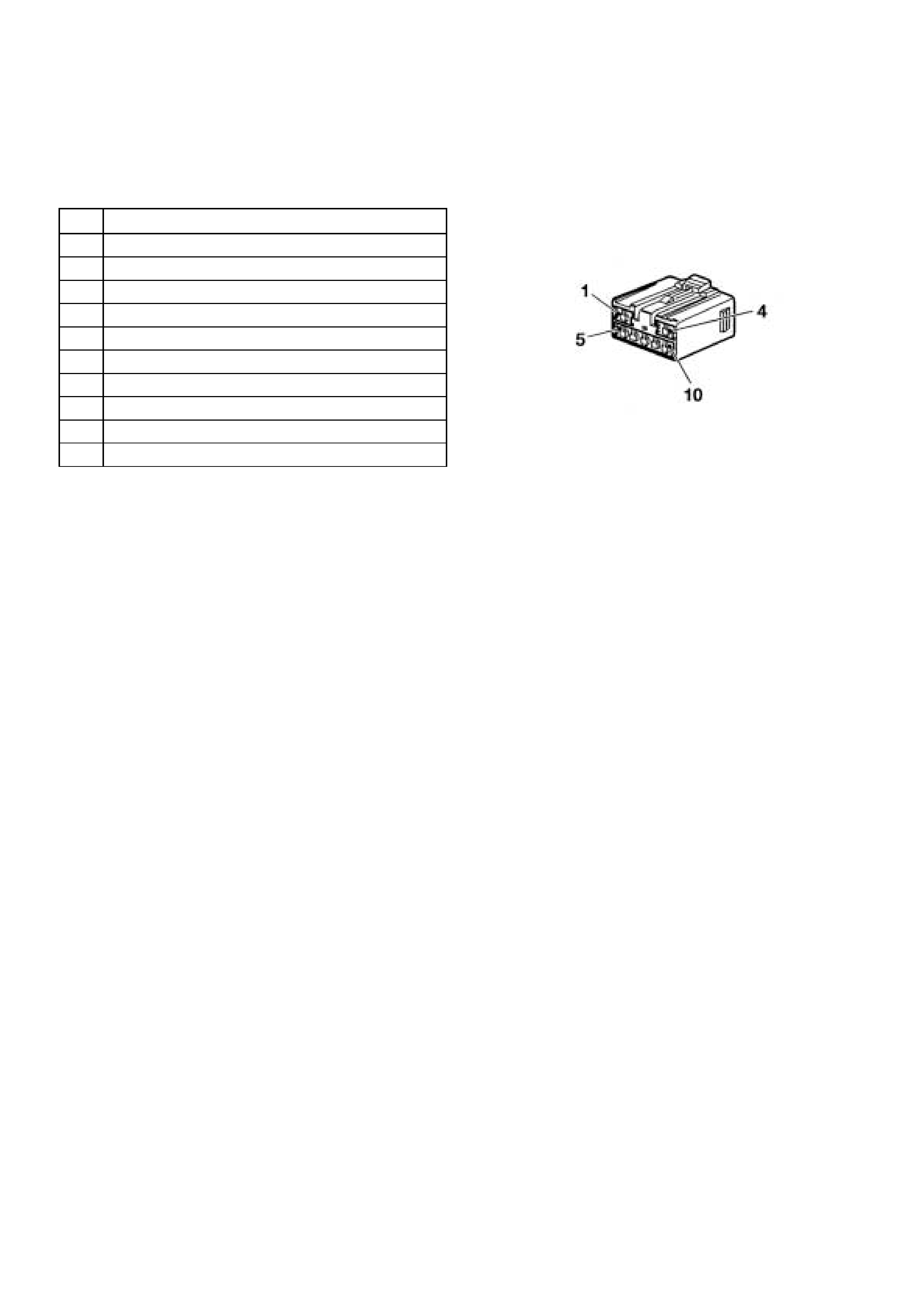
Immobiliser Control Unit Harness
Connector
Pin Circuit
1 Bat te ry Positi ve (1 0 A Fuse - C lo ck’B’)
2 PCM pin A13 Communication Line to ICU
3 Antenna Coil - Negat ive
4 Ground
5 Ignit ion (15A Engine Fuse)
6 ICU Comunication Line to PCM pin D7
7 Serial Data Line t o Diagnostic Link Connector Pi n 7
8 Vehicle Speed Sensor Signal Input
9 Antenna Coil - Positive
10 Imm obiliser Re lay Windi ngs
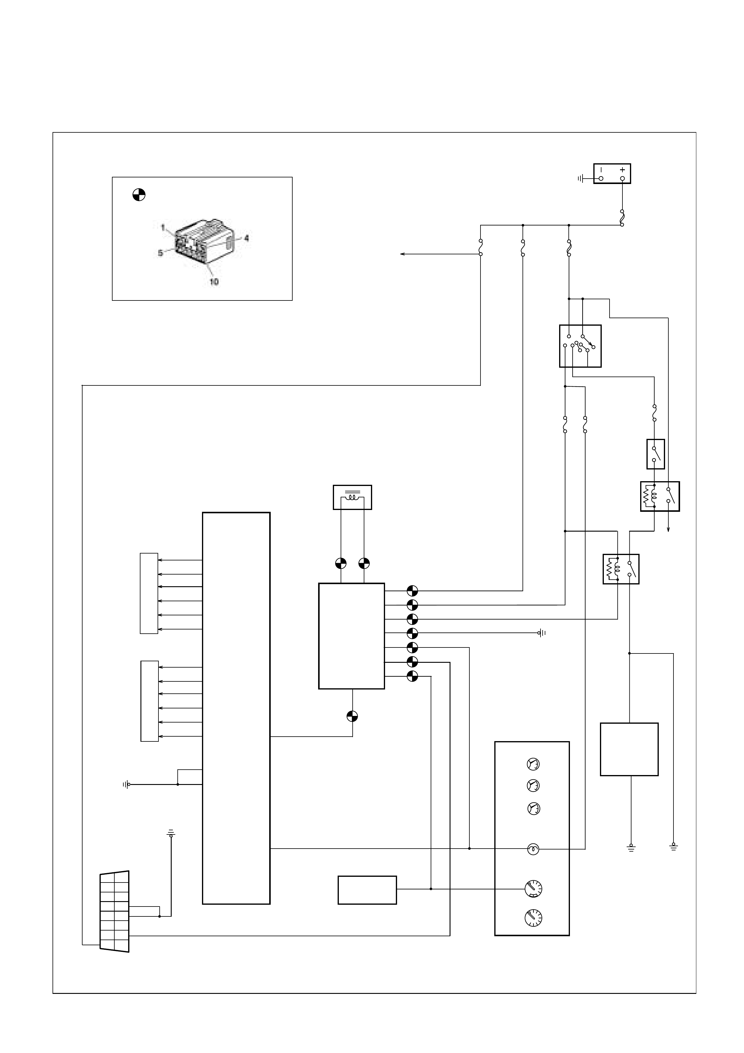
Wiring Diagram
ACC
B2
B1
OFF
IG2
ST
IG1
IGNITION
SWITCH
BATT
MAIN
80A
KEY SW.
50A
CLOCK (B)
10A
ENGINE
15A METER
10A
D1
D3
F13
F15
0.5B/L
A13
STOP
15A
SPEEDOMETER
INSTRUMENTS
TACHOMETER
OIL PRESSURE
ENG TEMPERATURE
CHECK ENG.
0.5L
9
0.5Y
C9
D7
PCM
1
9
2
10
3
11
4
12
5
13
6
14
7
15
8
16
8
7
2
4
10
5
1
3
ANTENNA COIL
0.5G/Y
0.5B
0.5B/Y
0.5R/W
0.5L
0.5O/B
0.5G/W
STARTER
10A
STARTER
MOTOR
IMMOBILISER
CONTROL
UNIT
IMMOBILISER
RELAY
STARTER
RELAY
FUEL LEVEL
MODE SW.
(AUTO)
6
VEHICLE SPEED
SENSOR
STOP
LAMPS
INJECTORS
C8
ANTI-THEFT
CONTROL
UNIT
22
17
Immobiliser Control Unit
Harness Connector
0.5W/B
W/O
ANTI-THEFT
C1
C3
IGNITION COILS
B4
C4
D5
D6
B2
B3