
SECTION 12C - METER AND GAUGE
Service Precaution
General Description
Meter Assembly
General Description
Layout for Meters/Gauges, Warning Lights, Indicator
Lights and Illumination Lights
Table for Meter/Gauge Connector Terminal
Connections
Removal
Warning Light Bulb, Indicator Light Bulb, Illumination
Light Bulb, A/T Indicator Light Bulb
Removal
Installation
Vehicle Speed Sensor
Removal
Installation
Fuel Tank Unit
Removal
Installation
Environment Meter
Removal
Installation
Ambient Sensor
Removal
Installation
Main Data and Specifications
Service Precaution
WARNING: IF SO EQUIPPED WITH A
SUPPLEMENTAL RESTRAINT SYSTEM (SRS),
REFER TO THE SRS COMPONENT AND WIRING
LOCATION VIEW IN ORDER TO DETERMINE
WHETHER YOU ARE PERFORMING SERVICE ON
OR NEAR THE SRS COMPONENTS OR THE SRS
WIRING. WHEN YOU ARE PERFORMING SERVICE
ON OR NEAR THE SRS COMPONENTS OR THE
SRS WIRING, REFER TO THE SRS SERVICE
INFORMATION. FAILURE TO FOLLOW WARNINGS
COULD RESULT IN POSSIBLE AIR BAG
DEPLOYMENT, PERSONAL INJURY, OR
OTHERWISE UNNEEDED SRS SYSTEM REPAIRS.
CAUTION: Always use the correct fastener in the
proper location. When you replace a fastener, use
ONLY the exact part number for that application.
HOLDEN will call out those fasteners that require a
replacement after removal. HOLDEN will also call out
the fasteners that require thread lockers or thread
sealant. UNLESS OTHERWISE SPECIFIED, do not
use supplemental coatings (Paints, greases, or
other corrosion inhibitors) on threaded fasteners or
fastener joint interfaces. Generally, such coatings
adversely affect the fastener torque and the joint
clamping force, and may damage the fastener.
When you install fasteners, use the correct
tightening sequence and specifications. Following
these instructions can help you avoid damage to
parts and systems.
General Description
The circuit consists of the starter switch, meter
assembly, vehicle speed sensor, transmission switch,
lighting switch, turn signal switch, thermo unit, oil
pressure unit, Powertrain Control Module (PCM), fuel
tank unit, 4WD switch, oil pressure switch, parking
brake switch, brake fluid switch, seat belt switch,
illumination controller, environment meter and ambient
sensor.
Techline
Techline
Meter Assembly
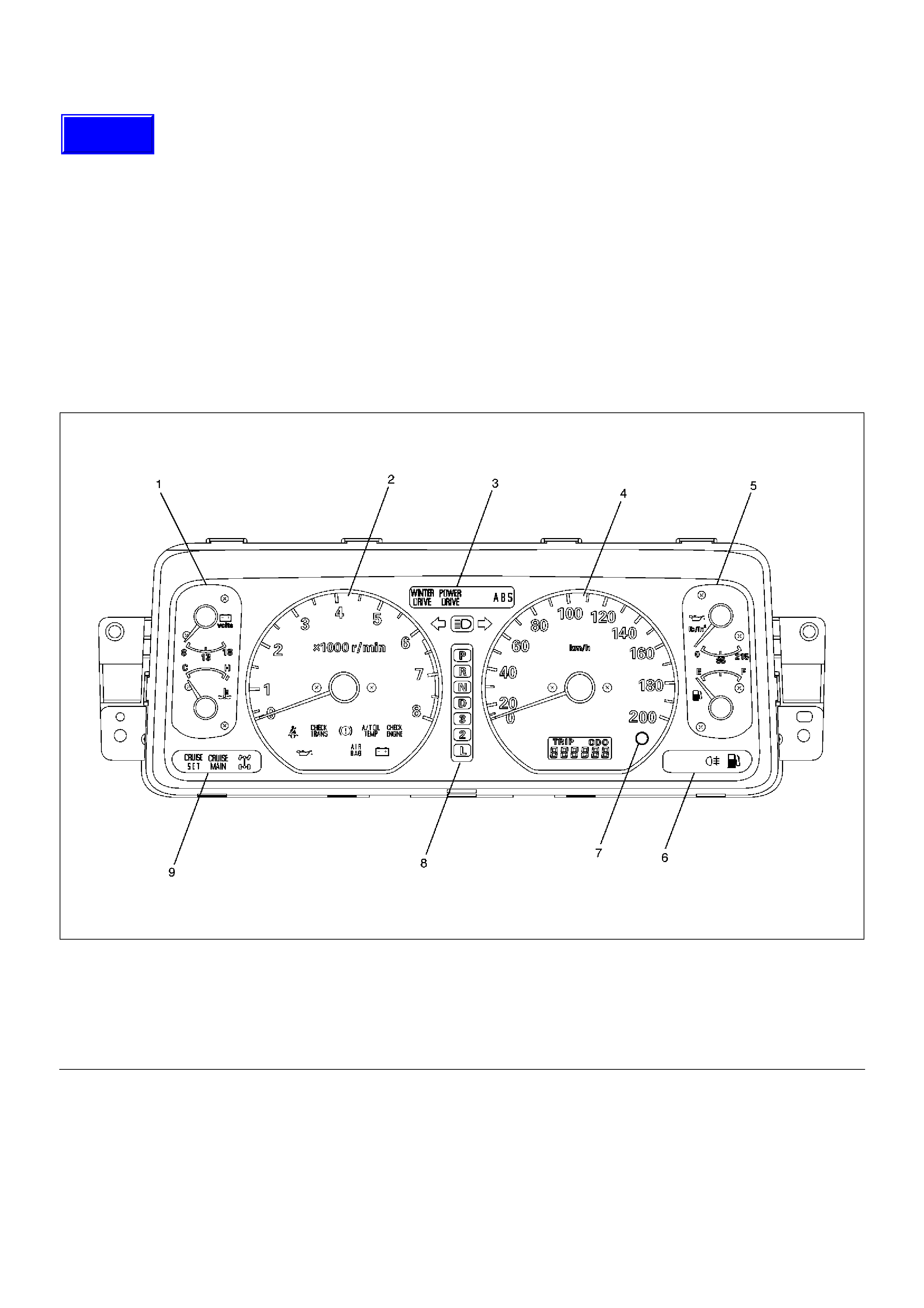
General Description
The meter assembly has the speedometer, tachometer,
engine coolant temperature gauge, fuel gauge and
warning/indicator lights. In addition, the meter
assembly containing TOD (Torque on Demand) has the
TOD indicator light, or the meter assembly not
containing TOD has the voltmeter and oil pressure
gauge instead of the TOD indicator.
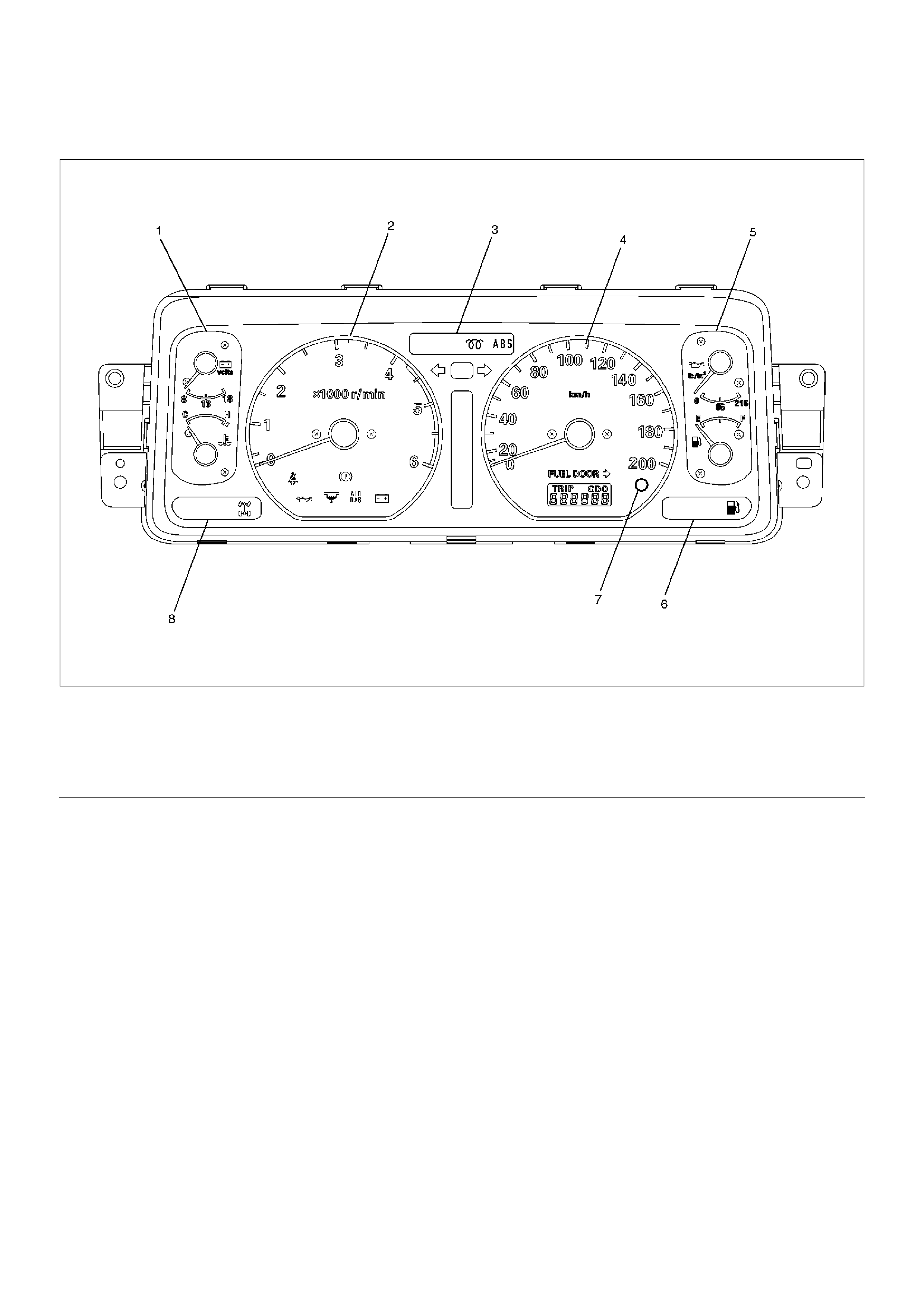
Layout for Meters/Gauges, Warning Lights, Indicator Lights and Illumination Lights
Meter Assembly– 6VE1 engine W/O TOD (Front View)
825RW207
EndOFCallout
Legend
(1) Voltmeter & Engine Coolant Temperature
Gauge
(2) Tachometer
(3) Warning Light Lens
(4) Speedometer
(5) Oil Pressure Gauge & Fuel Gauge
(6) Warning Light Lens
(7) Reset Knob
(8) A/T Shift Indicator
(9) Warning Light Lens
Techline
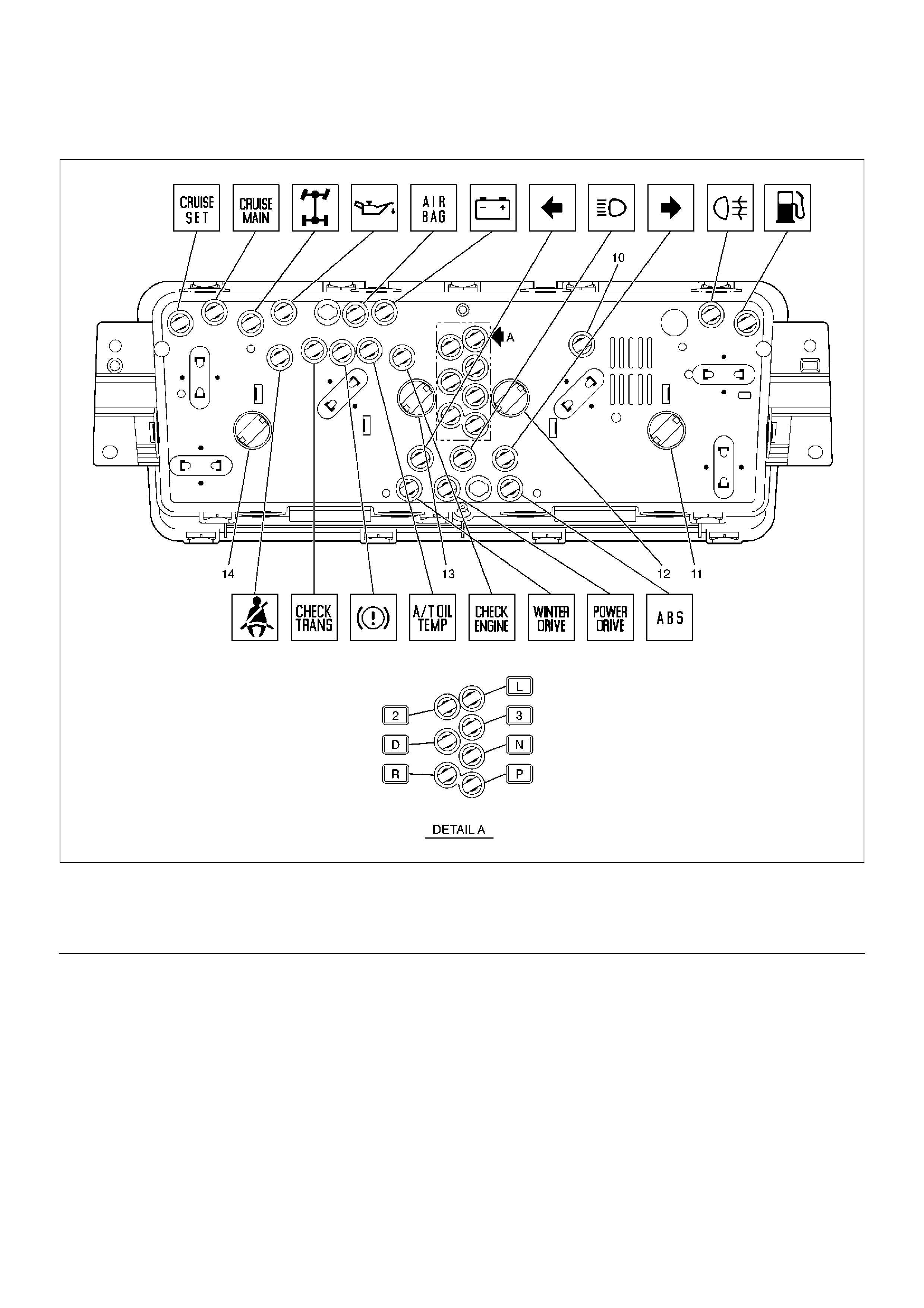
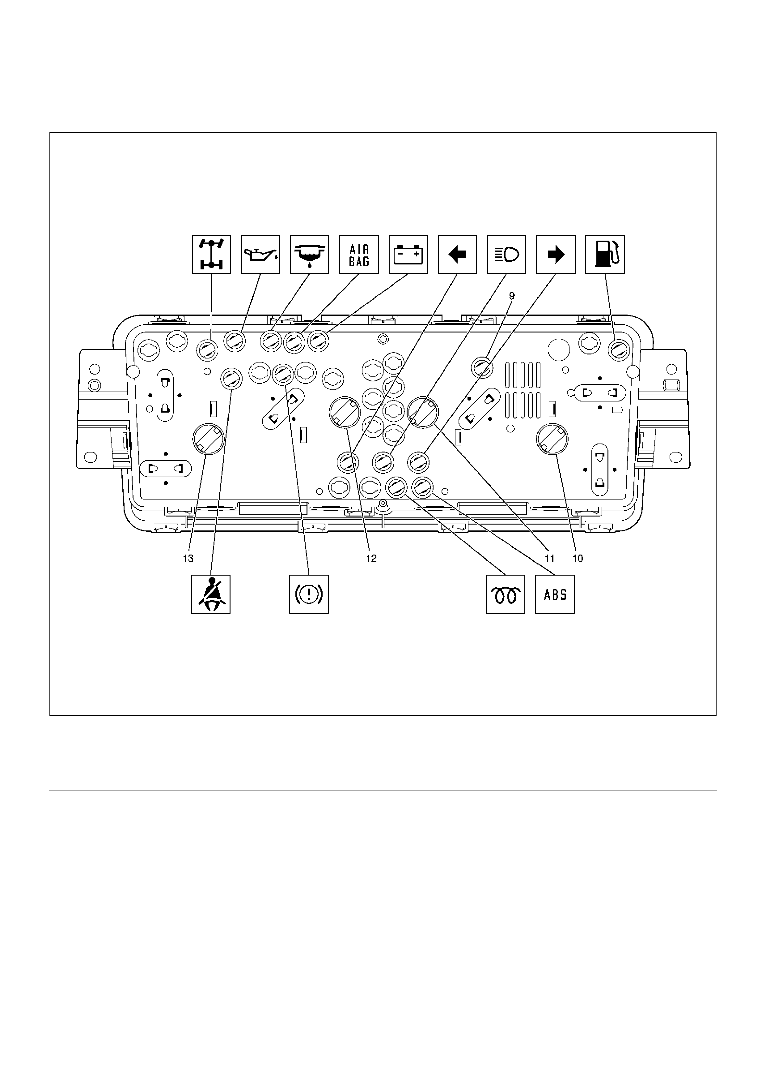
Meter Assembly– 6VE1 engine W/O TOD (Rear View)
825RW208
EndOFCallout
Legend
(10) LCD Light
(11) Illumination Light
(12) Illumination Light
(13) Illumination Light
(14) Illumination Light
Meter Assembly– 6VE1 engine W/TOD (Front View)
825RW210
EndOFCallout
Legend
(1) TOD Indicator
(2) Tachometer
(3) Warning Light Lens
(4) Speedometer
(5) Coolant Temperature Gauge & Fuel Gauge
(6) Warning Light Lens
(7) Reset Knob
(8) A/T Shift Indicator
(9) Warning Light Lens
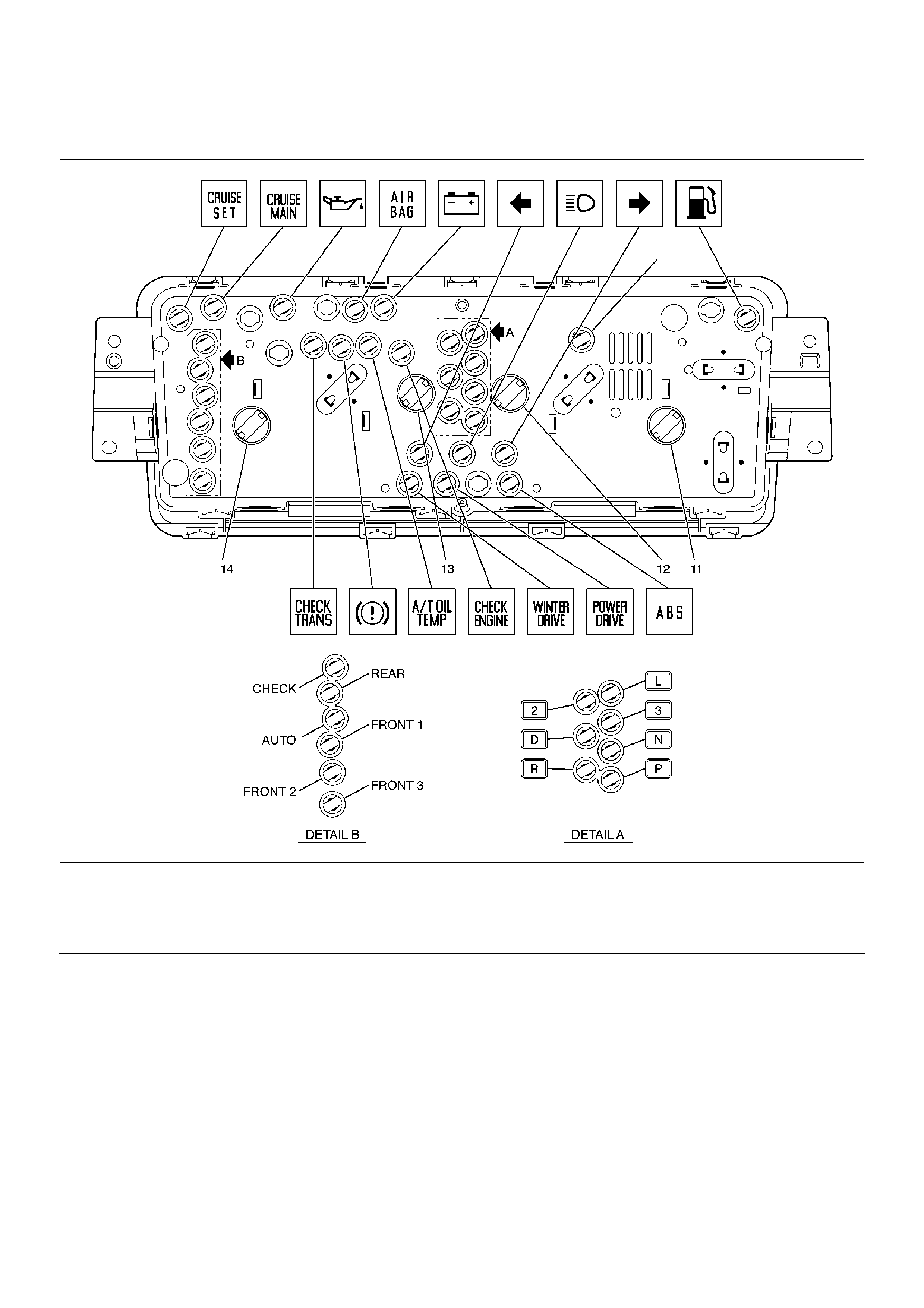
Meter Assembly– 6VE1 engine W/TOD (Rear View)
825RW212
EndOFCallout
Legend
(10) LCD Light
(11) Illumination Light
(12) Illumination Light
(13) Illumination Light
(14) Illumination Light
Meter Assembly– 4JX1 engine (Front View)
825RW211
EndOFCallout
Legend
(1) TOD Indicator
(2) Tachometer
(3) Warning Light Lens
(4) Speedometer
(5) Coolant Temperature Gauge & Fuel Gauge
(6) Warning Light Lens
(7) Reset Knob
(8) Warning Light Lens
Meter Assembly– 4JX1 engine (Rear View)
825RW232
EndOFCallout
Legend
(9) LCD Light
(10) Illumination Light
(11) Illumination Light
(12) Illumination Light
(13) Illumination Light
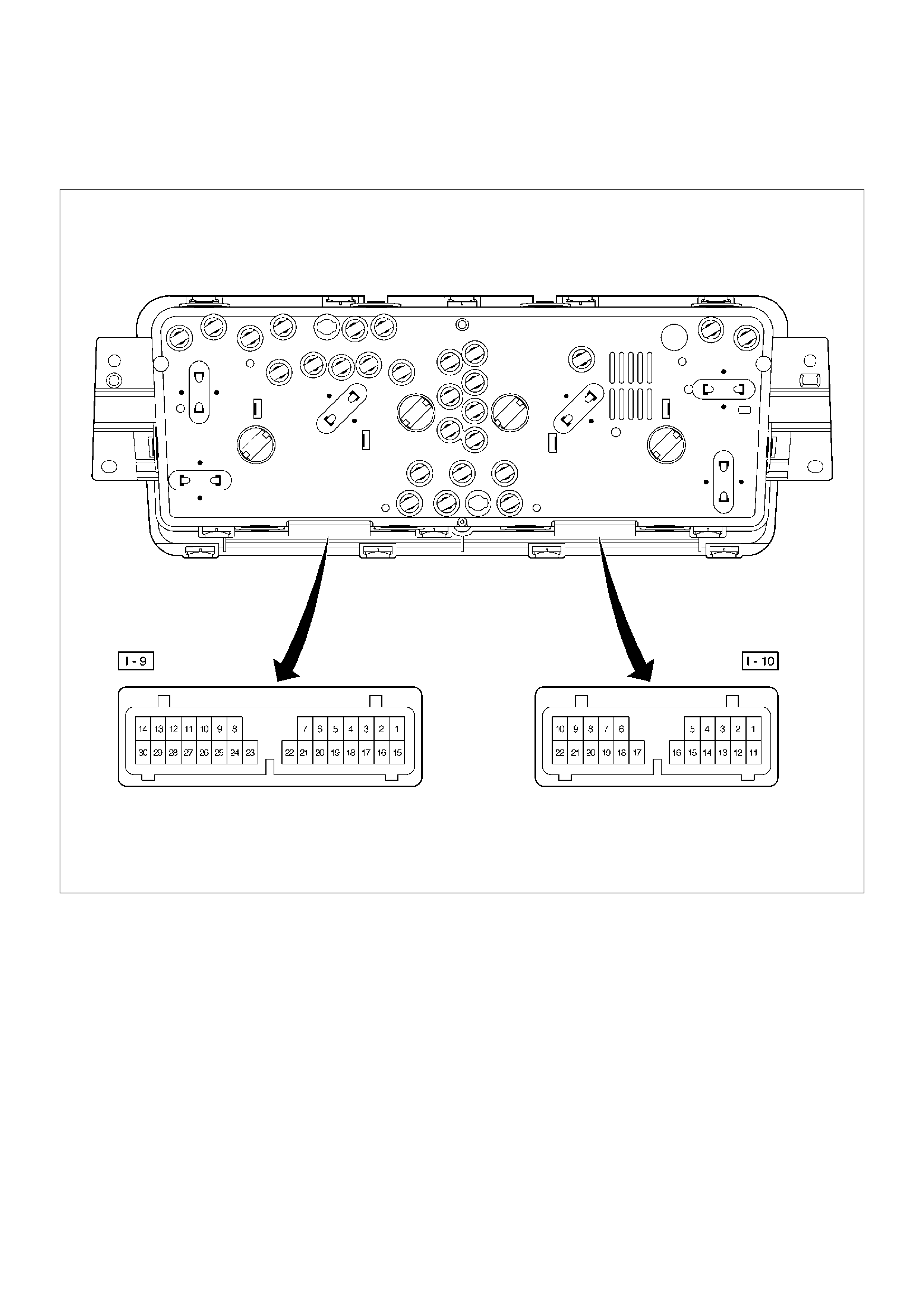
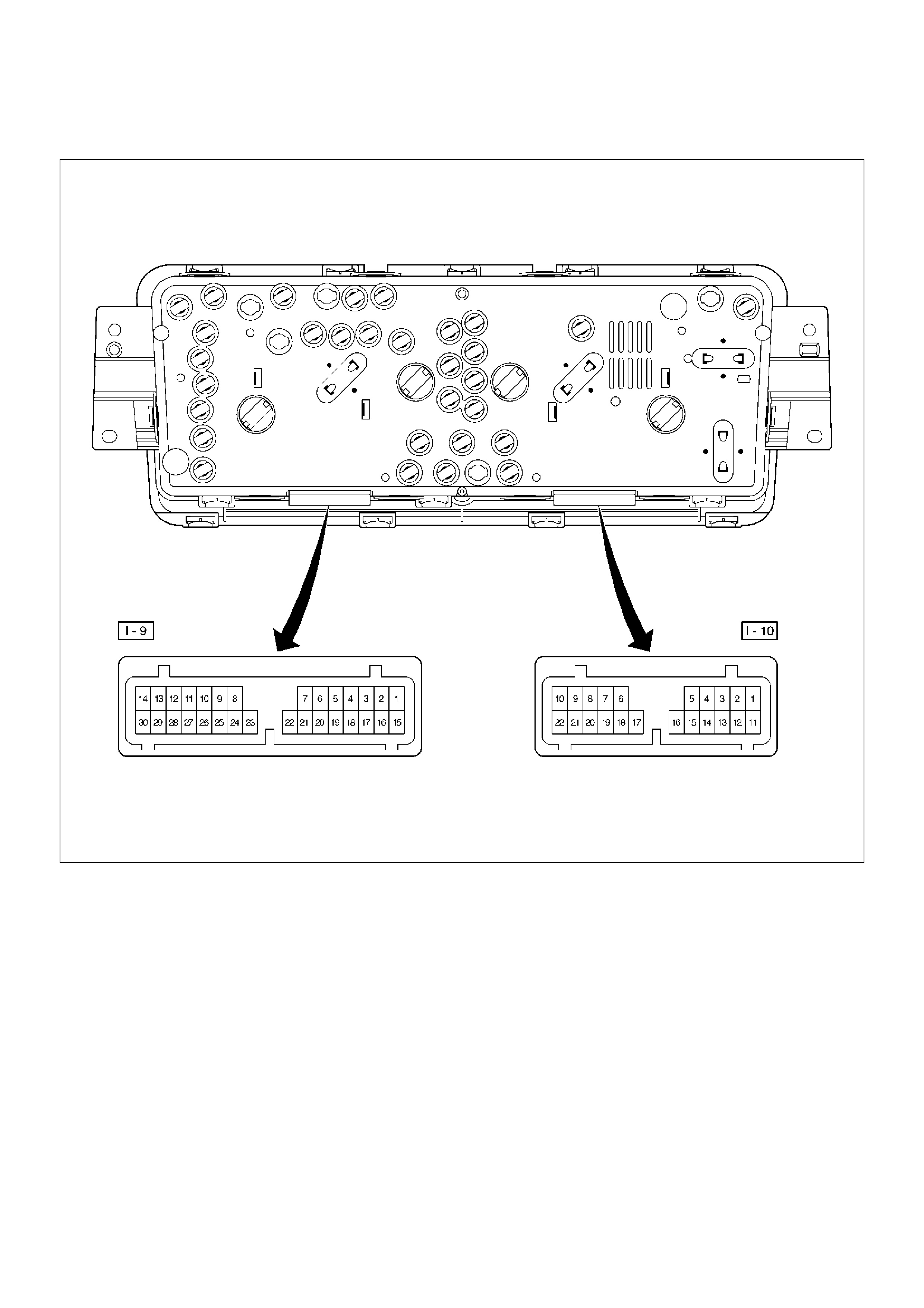
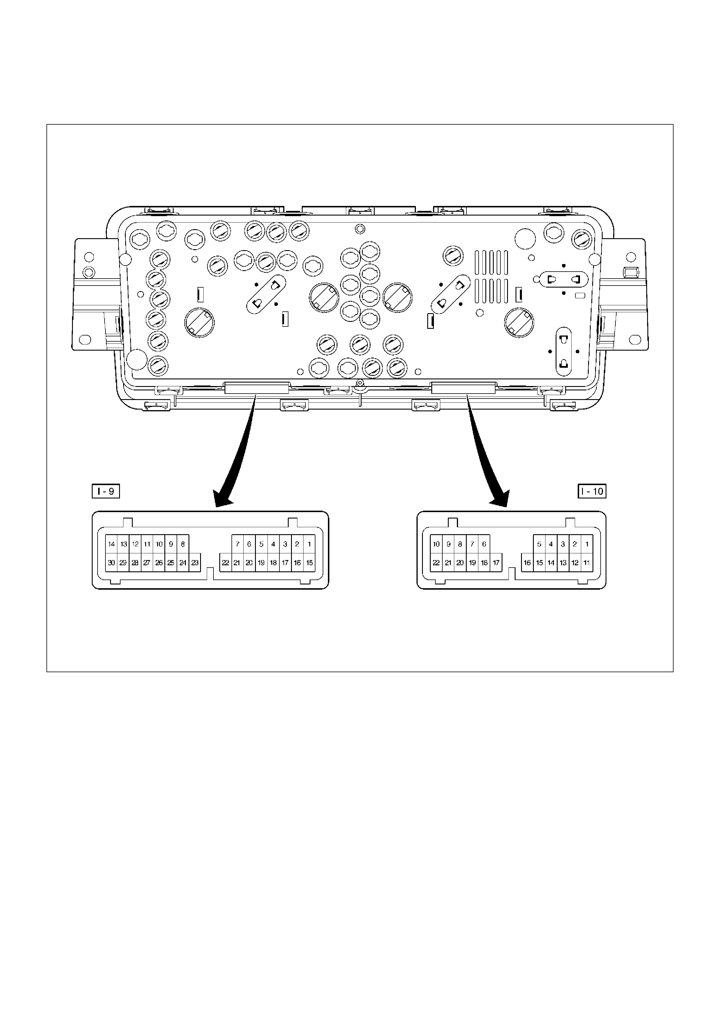
Table for Meter/Gauge Connector Terminal Connections
Meter Assembly– 6VE1 engine W/O TOD–1
825RW206
Meter Assembly–6VE1 engine W/O TOD–2
Connector No. I–9
Terminal Function
1 A/T oil temp warning light
2 Seat belt warning light
3 Check trans warning light
4 Brake warning light
5 Check engine warning light
6 Charge warning light
7 Cigarette lighter illumination light
8 Illumination controller
9 Tachometer
10 D position (A/T)
11 —
12 A/T shift indicator control unit
13 —
14 2 position (A/T)
15 Starter switch
16 Cruise set indicator light
17 Cruise main indicator light
18 4WD indicator light
19 Ground (Gauge)
20 —
21 Winter drive indicator light
22 Oil pressure warning light
23 —
24 Air bag warning light
25 Power drive indicator light
26 —
27 —
28 Turn signal indicator light (Left)
29 —
30 Ground
Connector No. I–10
Terminal Function
1 Turn signal indicator light (Right)
2 L position (A/T)
3 R position (A/T)
4 Engine coolant temperature gauge
5 Speedometer
6—
7—
8Battery (+)
9—
10 Rear fog light
11 P position (A/T)
12 N position (A/T)
13 3 position (A/T)
14 High-beam indicator light (-)
15 High-beam indicator light (+)
16 ABS indicator light
17 —
18 Fuel warning light
19 Oil pressure gauge
20 Fuel gauge
21 —
22 —
Meter Assembly–6VE1 engine W/TOD–1
825RW209
Meter Assembly–6VE1 engine W/TOD–2
Connector No. I–9
Terminal Function
1—
2 Air bag warning light
3 A/T oil temp warning light
4 Charge warning light
5 Check engine warning light
6 Check trans warning light
7 Brake warning light
8—
9 Tachometer
10 —
11 Turn signal indicator light (Left)
12 A/T shift indicator control unit
13 2 position (A/T)
14 D position (A/T)
15 Rear (TOD)
16 Auto (TOD)
17 Check (TOD)
18 Cruise set indicator light
19 Cruise main indicator light
20 Oil pressure warning light
21 Front “1” (TOD)
22 Front “2” (TOD)
23 Front “3” (TOD)
24 Cigarette lighter illumination light
25 Illumination controller
26 Starter switch
27 —
28 Winter drive indicator light
29 Power drive indicator light
30 —
Connector No. I–10
Terminal Function
1 Turn signal indicator light (Right)
2 L position (A/T)
3 R position (A/T)
4 Check engine warning light
5 Speedometer
6—
7—
8Battery (+)
9 Engine coolant temperature gauge
10 Ground
11 P position (A/T)
12 N position (A/T)
13 3 position (A/T)
14 High beam indicator light (-)
15 High beam indicator light (+)
16 ABS indicator light
17 —
18 Fuel warning light
19 —
20 Fuel gauge
21 Ground (Gauge)
22 —
Meter Assembly–4JX1 engine –1
825RW233

Meter Assembly–4JX1 engine –2
Connector No. I–9
Terminal Function
1—
2 Seat belt warning light
3—
4 Brake warning light
5—
6 Charge warning light
7 Cigarette lighter illumination light
8 Illumination controller
9 Tachometer
10 —
11 —
12 —
13 —
14 —
15 Starter switch
16 —
17 —
18 4WD indicator light
19 Ground (Gauge)
20 —
21 —
22 Oil pressure warning light
23 Water sedimenter
24 Air bag warning light
25 —
26 Glow indicator light
27 —
28 Turn signal indicator light (Left)
29 —
30 Ground
Connector No. I–10
Terminal Function
1 Turn signal indicator light (Right)
2—
3—
4 Engine coolant temperature gauge
5 Speedometer
6—
7—
8Battery (+)
9—
10 —
11 —
12 —
13 —
14 High-beam indicator light (-)
15 High-beam indicator light (+)
16 ABS indicator light
17 —
18 Fuel warning light
19 Oil pressure gauge
20 Fuel gauge
21 —
22 —
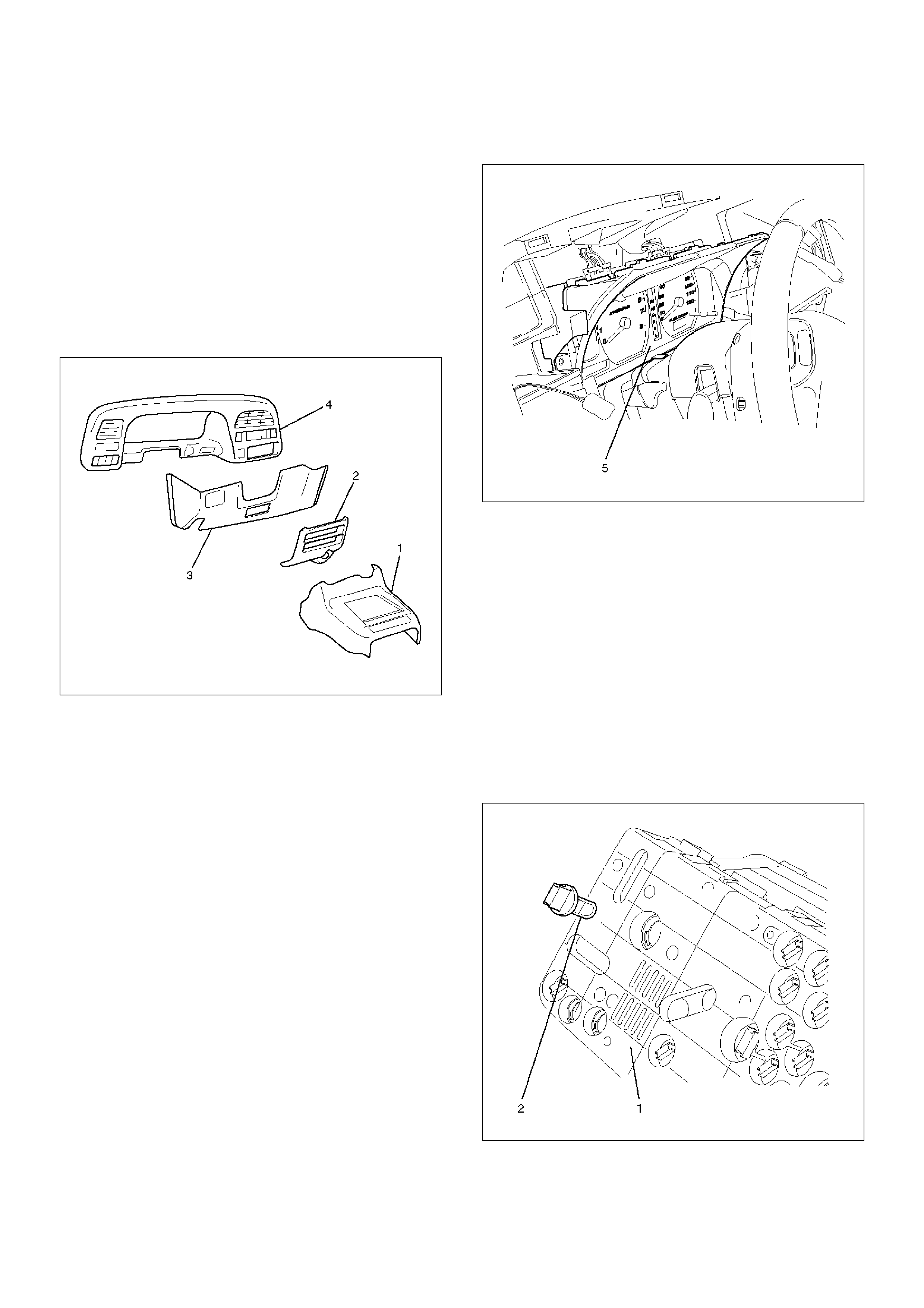
Removal
1.Disconnect the battery ground cable.
2.Remove the front console assembly(1).
Refer to the Instrument Panel Assembly in Body
Structure section.
3.Remove the lower cluster assembly(2).
Refer to the Instrument Panel Assembly in Body
Structure section.
4.Remove the instrument panel driver lower cover(3).
Refer to the Instrument Panel Assembly in Body
Structure section.
740RS004
5.Remove four fixing screws and disconnect the
meter connectors to remove the meter assembly(5).
825RW031
CAUTION: The removed meter assembly should be
placed upright or with its face side up.
Installation
To install, follow the removal steps in the reverse order.
Warning Light Bulb, Indicator Light Bulb, Illumination Light Bulb, A/T Indicator
Light Bulb
Removal
1.Disconnect the battery ground cable.
2.Remove the meter assembly(1).
Refer to the Meter Assembly removal steps in this
section.
3. Hold the bulb socket by hand and rotate it
counterclockwise to remove the socket & bulb(2)
from the meter body.
825RW032
Installation
To install, follow the removal steps in the reverse order.
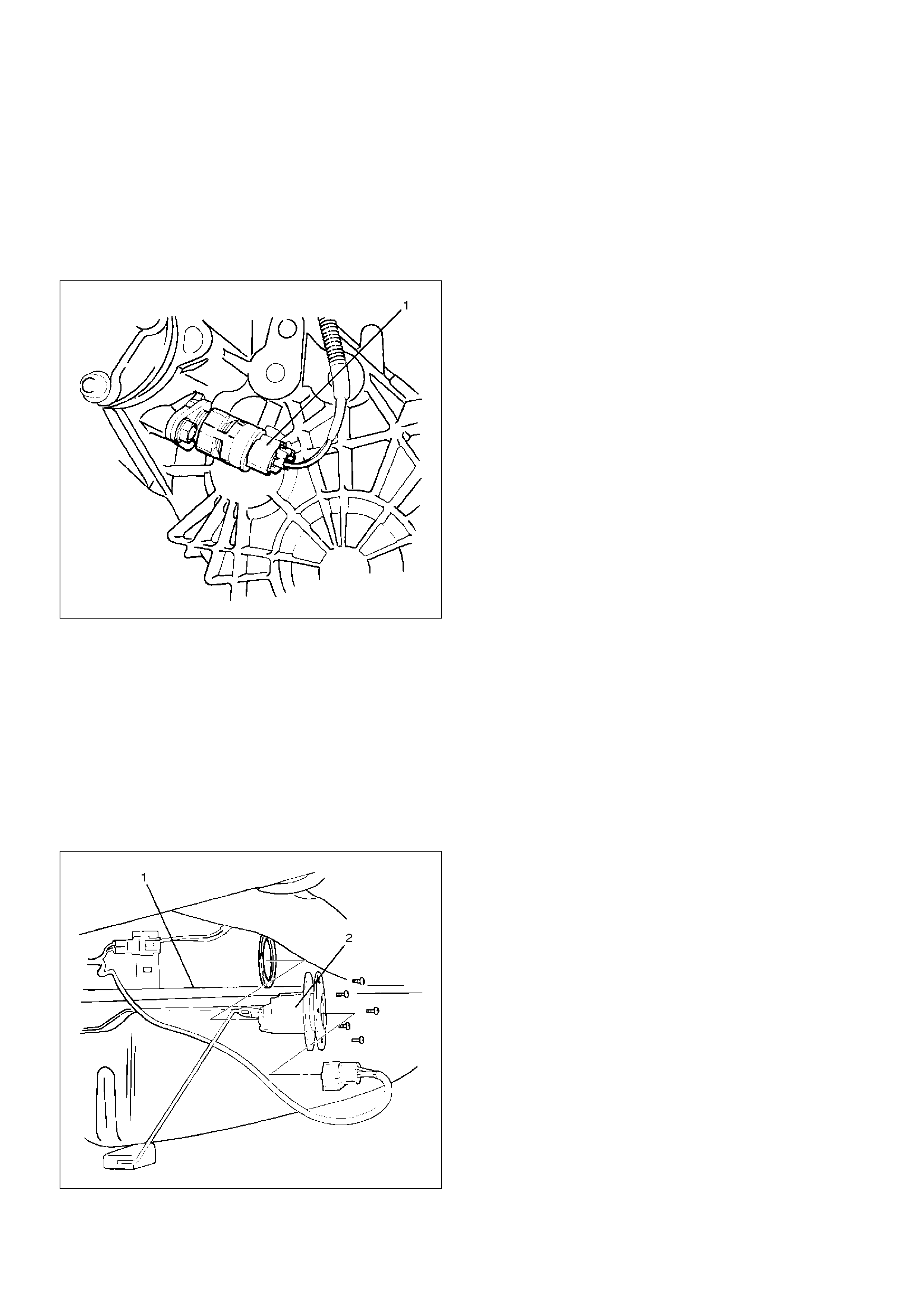
Vehicle Speed Sensor
Removal
1.Disconnect the battery ground cable.
2.Disconnect the connector, remove the vehicle
speed sensor body by rotating it and then remove
the vehicle speed sensor(1).
826RS009
Installation
To install, follow the removal steps in the reverse order,
noting the following point.
1.Tighten the vehicle speed sensor to the specified
torque.
Torque: 27N·m (2.8 kg·m/20lbft)
Fuel Tank Unit
Removal
1.Disconnect the battery ground cable.
2.Remove the fuel tank(1).
Refer to the Fuel Tank removal steps in Engine
section
3. Disconnect the connectors, remove five screws and
then remove the fuel tank unit(2).
140RS006
Installation
To install, follow the removal steps in the reverse order.
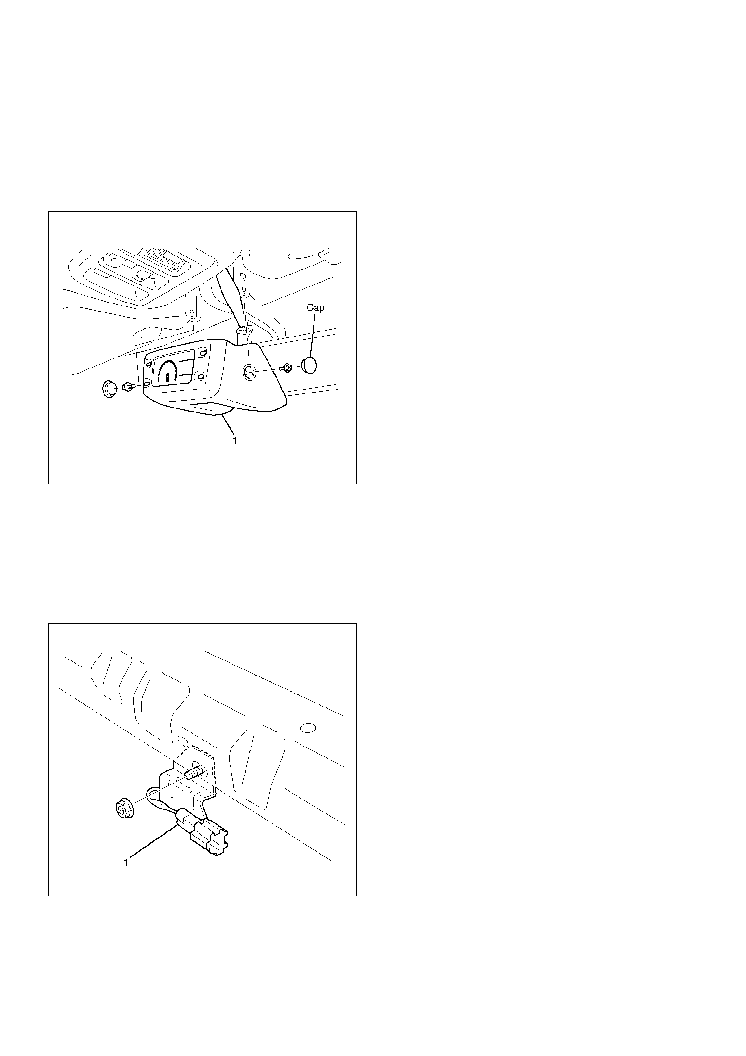
Environment Meter
Removal
1. Disconnect the battery ground cable.
2. Remove two caps, two screws and disconnect the
connector to remove the multi meter(1).
821RW036
Installation
To install, follow the removal steps in the reverse order.
Ambient Sensor
Removal
1. Disconnect the battery ground cable.
2. Disconnect the connector and remove the nut to
remove the ambient sensor(1).
821RW035
Installation
To install, follow the removal steps in the reverse order.

Main Data and Specifications
Torque Specifications
Application N·m kg·m LbFt LbIn
Vehicle Speed Sensor Fixing 27 2.8 20 —