
SECTION 12D- ENTERTAINMENT
Service Precaution
Cigarette Lighter
General Description
Removal
Installation
Digital Clock
Removal
Installation
Rod Type Antenna
Removal
Installation
Auto Antenna
General Description
Removal
Installation
Antenna Rod
Removal
Installation
Radio
Removal
Installation
Radio
Removal
Installation
Front Speaker
Removal
Installation
Rear Speaker
Removal
Installation
Service Precaution
WARNING: IF SO EQUIPPED WITH A
SUPPLEMENTAL RESTRAINT SYSTEM (SRS),
REFER TO THE SRS COMPONENT AND WIRING
LOCATION VIEW IN ORDER TO DETERMINE
WHETHER YOU ARE PERFORMING SERVICE ON
OR NEAR THE SRS COMPONENTS OR THE SRS
WIRING. WHEN YOU ARE PERFORMING SERVICE
ON OR NEAR THE SRS COMPONENTS OR THE
SRS WIRING, REFER TO THE SRS SERVICE
INFORMATION. FAILURE TO FOLLOW WARNINGS
COULD RESULT IN POSSIBLE AIR BAG
DEPLOYMENT, PERSONAL INJURY, OR
OTHERWISE UNNEEDED SRS SYSTEM REPAIRS.
CAUTION: Always use the correct fastener in the
proper location. When you replace a fastener, use
ONLY the exact part number for that application.
ISUZU will call out those fasteners that require a
replacement after removal. ISUZU will also call out
the fasteners that require thread lockers or thread
sealant. UNLESS OTHERWISE SPECIFIED, do not
use supplemental coatings (Paints, greases, or
other corrosion inhibitors) on threaded fasteners or
fastener joint interfaces. Generally, such coatings
adversely affect the fastener torque and the joint
clamping force, and may damage the fastener.
When you install fasteners, use the correct
tightening sequence and specifications. Following
these instructions can help you avoid damage to
parts and systems.
Cigarette Lighter
General Description
When the cigarette lighter is pushed in with the starter
switch at either “ACC” or “ON” position, a circuit is
formed in the cigarette lighter case to heat the lighter
coil.
The cigarette lighter is sprung back to its original
position after the lighter coil is heated.
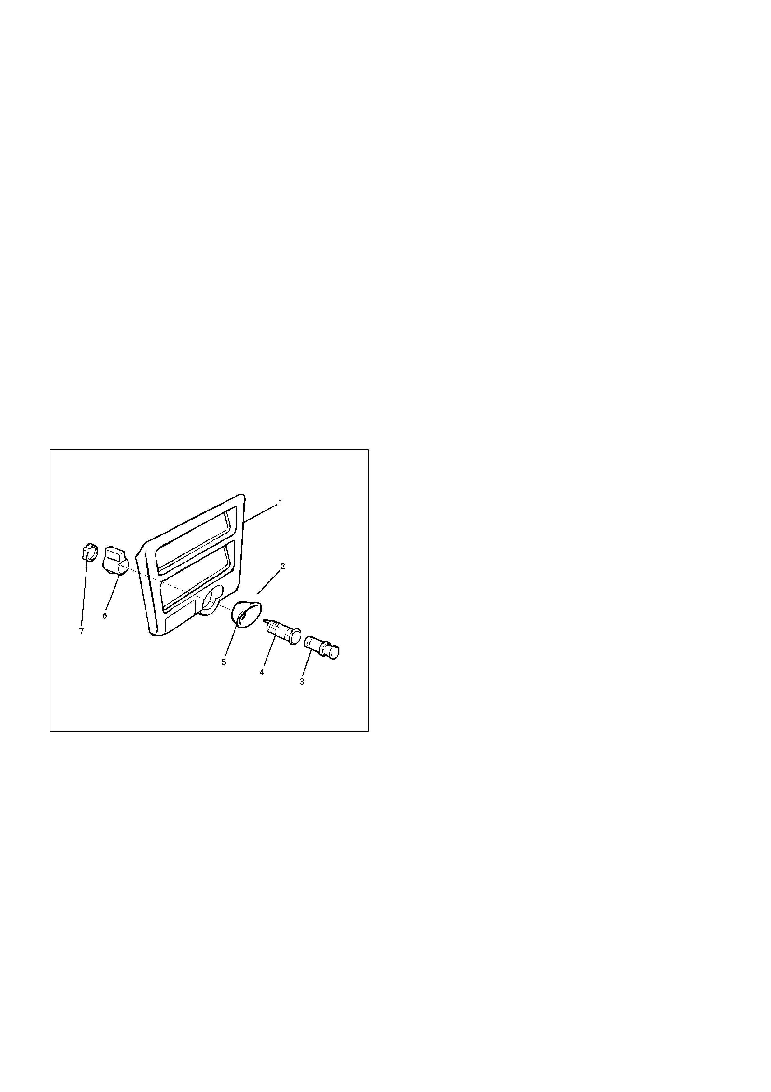
Removal
1.Disconnect the battery ground cable.
2.Remove the lower cluster assembly(1).
Refer to the Instrument Panel Assembly removal
steps in Body Structure section.
3. Disconnect the connectors, remove the socket of
the illumination light, the retaining ring(7), the outer
case(6), the cigarette lighter(3) and socket(4), the
bezel(5) and then remove the cigarette lighter
assembly(2).
826RS007
Installation
To install, follow the removal steps in the reverse order,
noting the following point.
1. When installing the bezel, align the projected portion
of the socket with the notch of the bezel.
Digital Clock
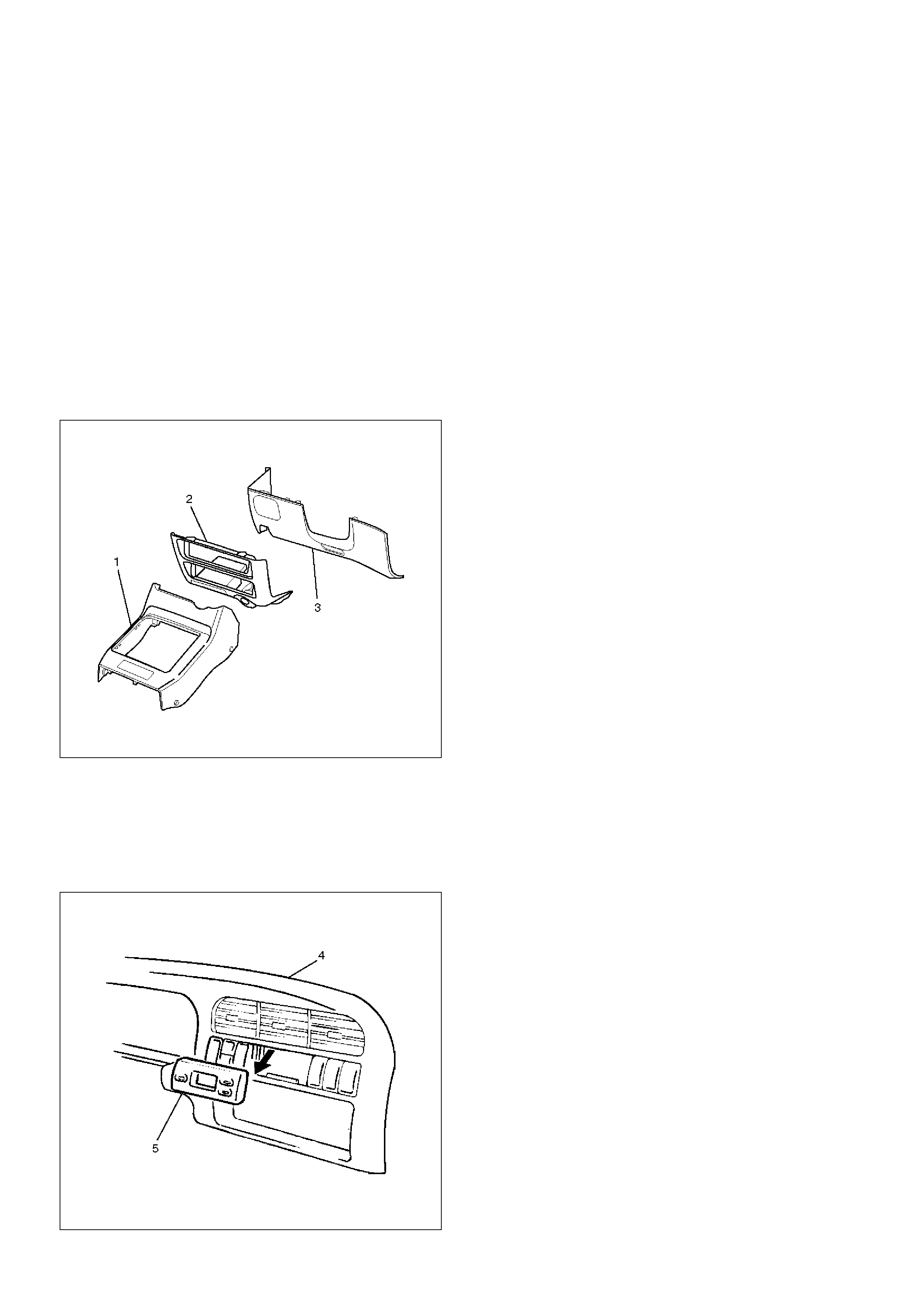
Removal
1.Disconnect the battery ground cable.
2.Remove the front console assembly(1).
Refer to the Instrument Panel Assembly in Body
Structure section.
3.Remove the lower cluster assembly(2).
Refer to the Instrument Panel Assembly in Body
Structure section.
4.Remove the instrument panel driver lower cover
assembly(3).
Refer to the Instrument Panel Assembly in Body
Structure section.
821RW024
5.Remove the instrument panel cluster assembly(4).
Refer to the Instrument Panel Assembly in Body
Structure section.
6. Disconnect the connector and push the lock from
the back side of the instrument panel cluster
assembly to remove the digital clock(5).
821RW034
Installation
To install, follow the removal steps in the reverse order,
noting the following point.
1. Push in the switch with your fingers until it locks
securely.
Rod Type Antenna
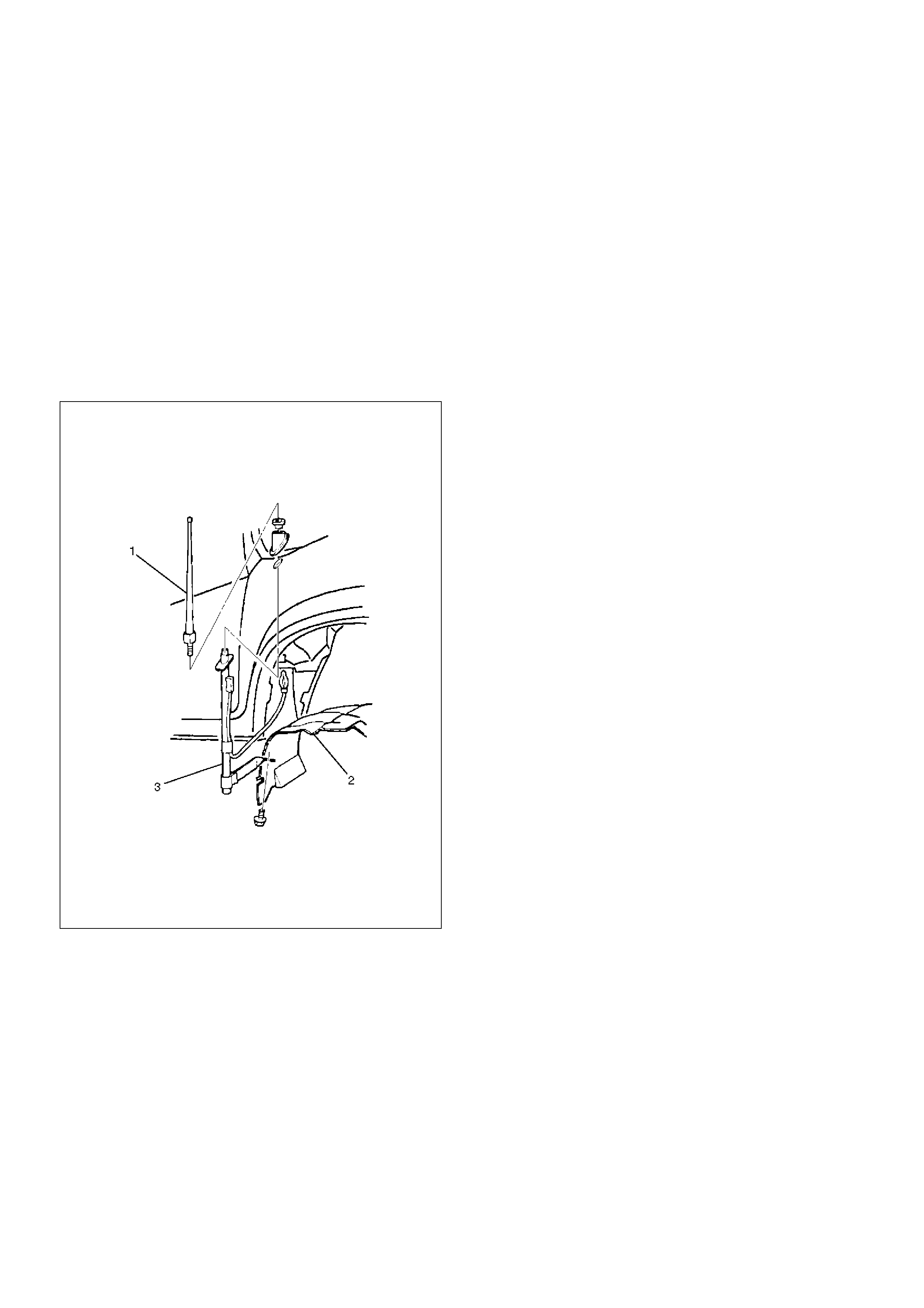
Removal
1. Disconnect the battery ground cable.
2. Turn the antenna rod(1) counterclockwise to remove
it.
3. Remove three screws and nine clips to remove the
fender inner liner(2).
4. Disconnect the feeder cable connector at the inside
of the vehicle, remove the housing bracket screw,
turn the lock nut counterclockwise to remove it
together with the base mold and then remove the
housing(3).
890RS004
Installation
To install, follow the removal steps in the reverse order.
Auto Antenna
General Description
The auto antenna is interlocked with the radio switch.
The antenna rod goes up when the switch is on, and
goes down when the switch is off. The antenna rod also
goes down when the starter switch is turned off with the
radio on.
The antenna rod goes up or down when the cable
connected to the uppermost rod is let out or taken up by
the rotation of motor.
The motor is provided with a built-in limit switch. When
the up/down motion of the antenna is completed, the
limit switch is activated to cut off the circuit.
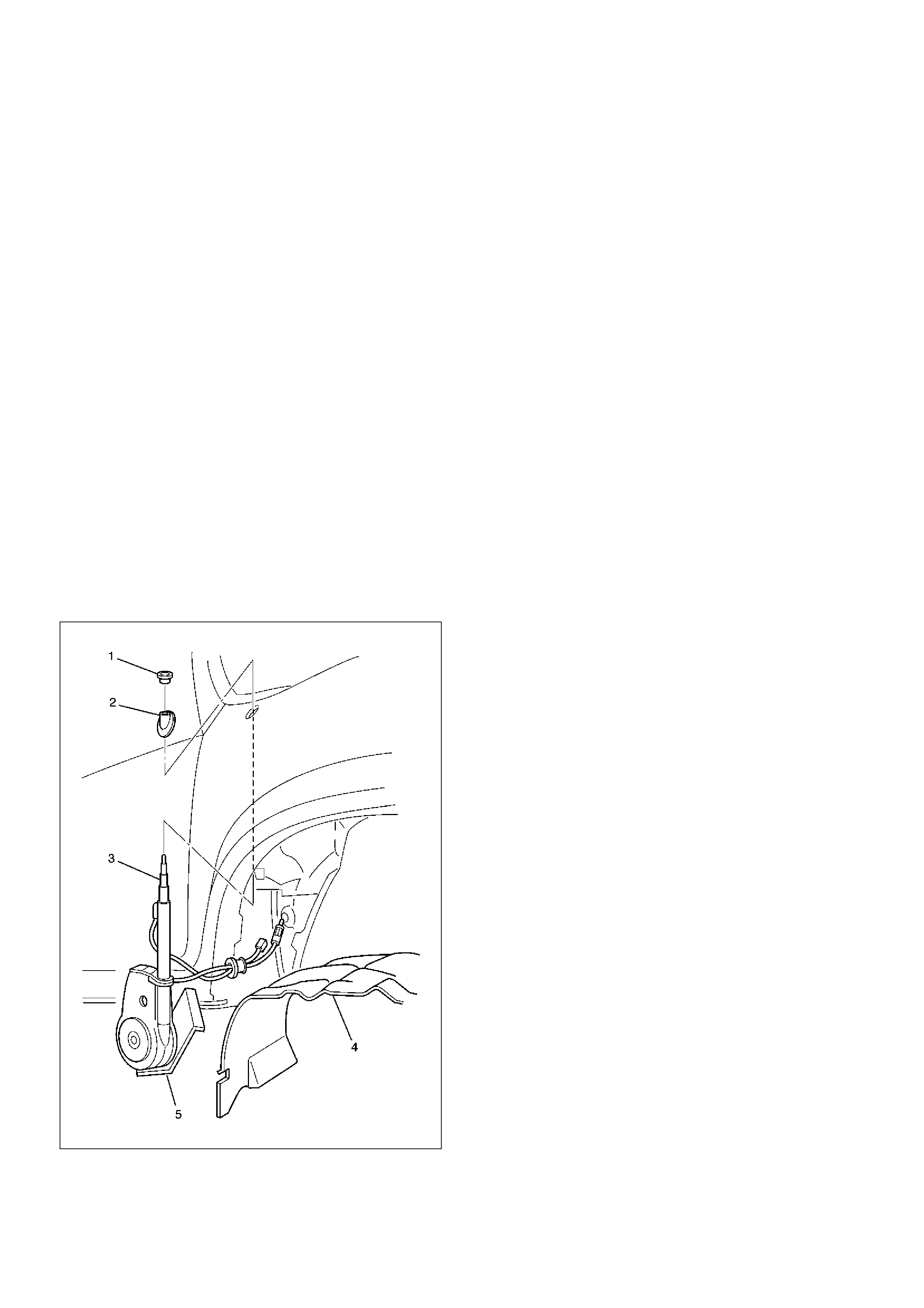
Removal
1. Disconnect the battery ground cable.
2. Remove three screws and nine clips to remove the
fender inner liner(4).
3. Disconnect the feeder cord and the antenna motor
connector at the inside of the vehicle.
4. Remove the lock nut(1) and base mold(2).
5. After taking off the clips and screws, remove the
motor bracket(5).
890RW075
Installation
To install, follow the removal steps in the reverse order.
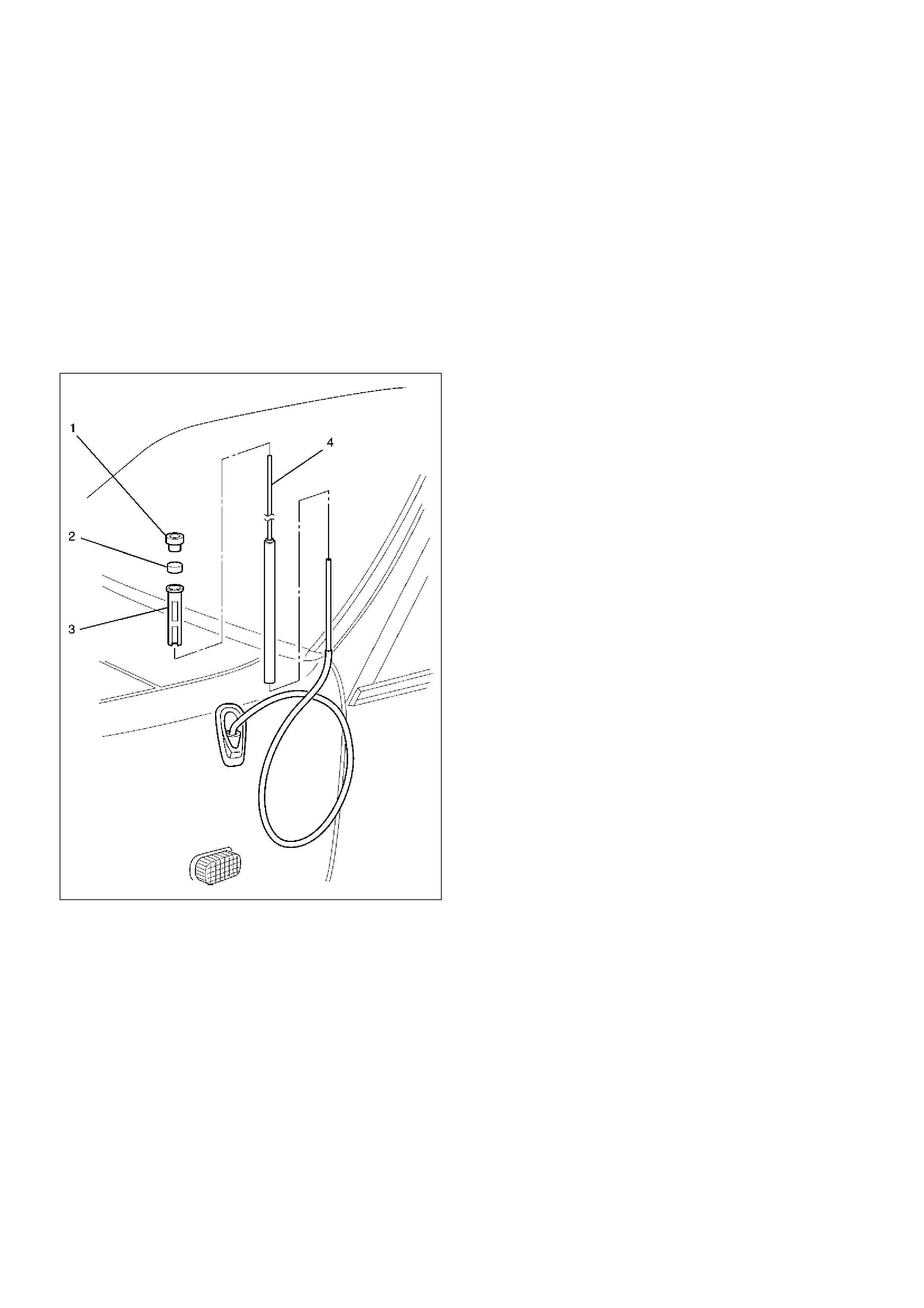
Antenna Rod
Removal
1. Disconnect the battery ground cable.
2. Remove the antenna nut(1).
3. Until the lower part of the antenna rod(4) is removed
from the bezel part, rotate the antenna motor in an
ascending way, and expand the rod.
4. Turn the antenna top(2) counterclockwise.
5. Remove the contact sleeve(3).
6. Remove the antenna rod(4).
890RW076
Installation
To install, follow the removal steps in the reverse order,
nothing the following points.
1. Rotate the antenna motor in a descend way, and
push in vertically until the antenna rod is in the
complete state of storage.
2. After ending the installation, confirm that the
antenna rod works correctly.
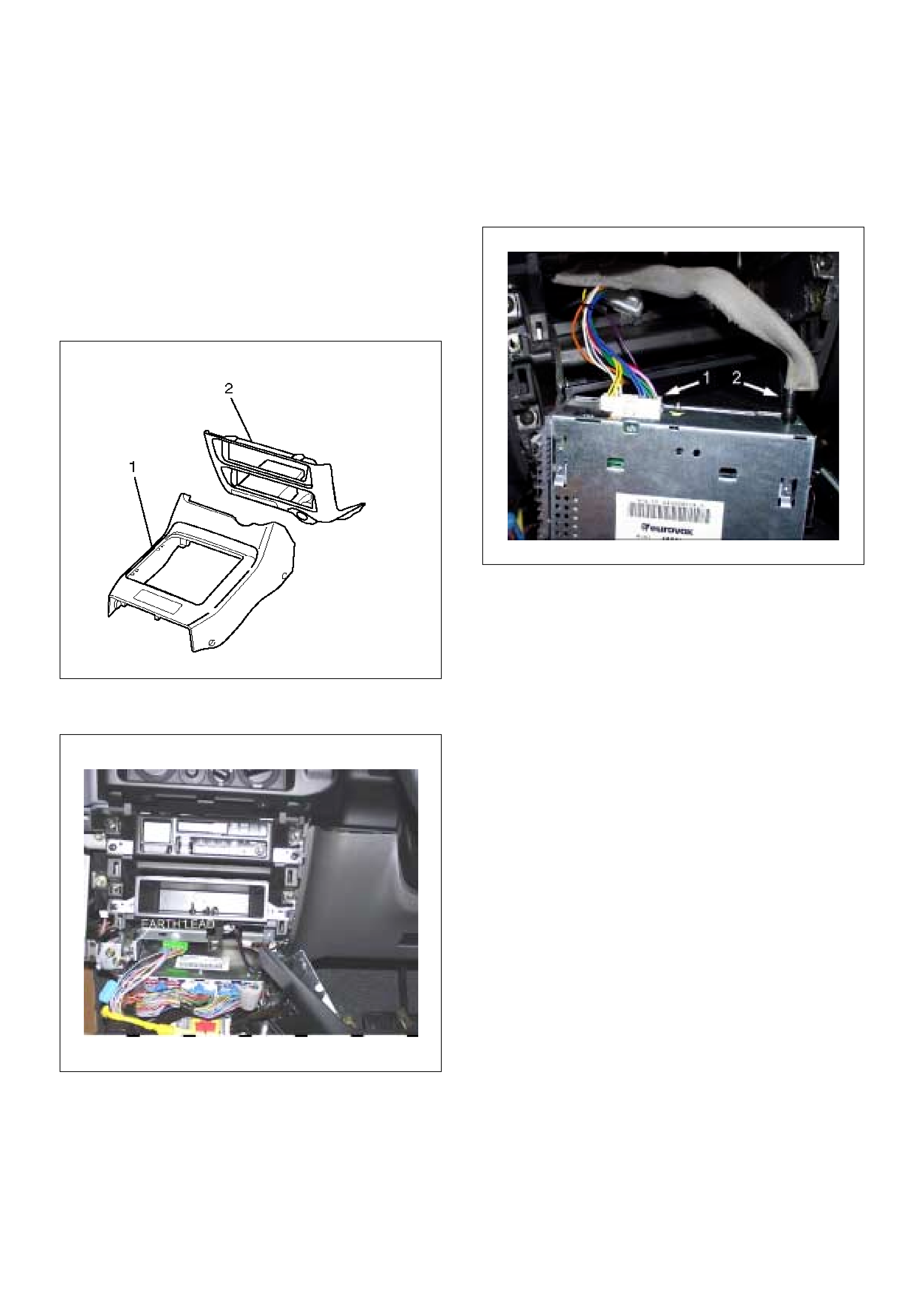
Radio
Removal
1. Disconnect the battery ground cable.
2. Remove the four screws securing the centre
console assembly (1), and remove the console.
3. Remove the three screws securing the lower cluster
assembly (2), and carefully remove the lower cluster
from instrument panel.
821RW024
4. Remove the 6mm nut securing the radio earth strap.
5. Remove two screws and disconnect the radio
connector (1) and the antenna feeder plug (2) to
remove the radio
825RW039
Installation
To install, follow the removal steps in the reverse order.,
enter the radio security code and test all functions.
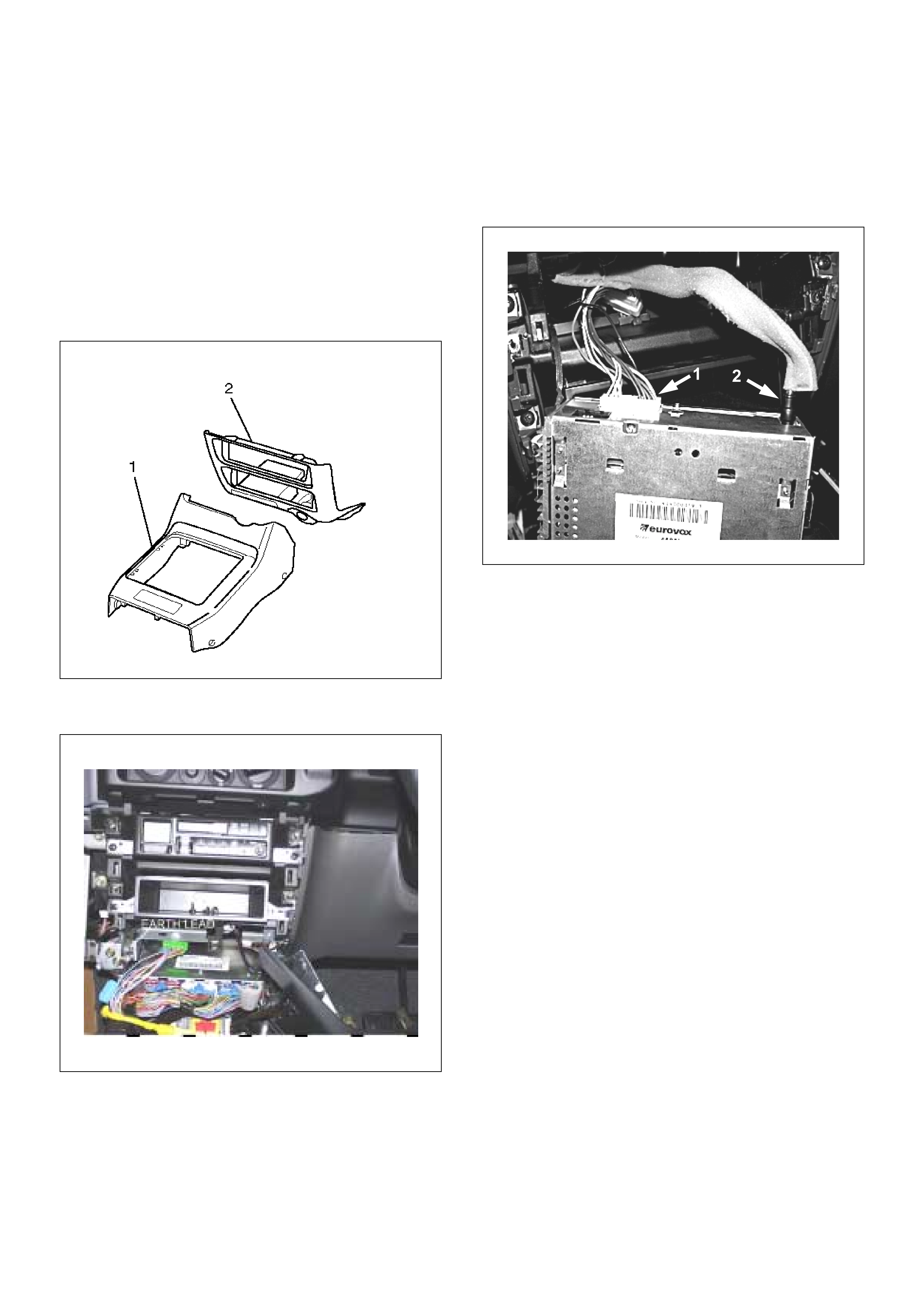
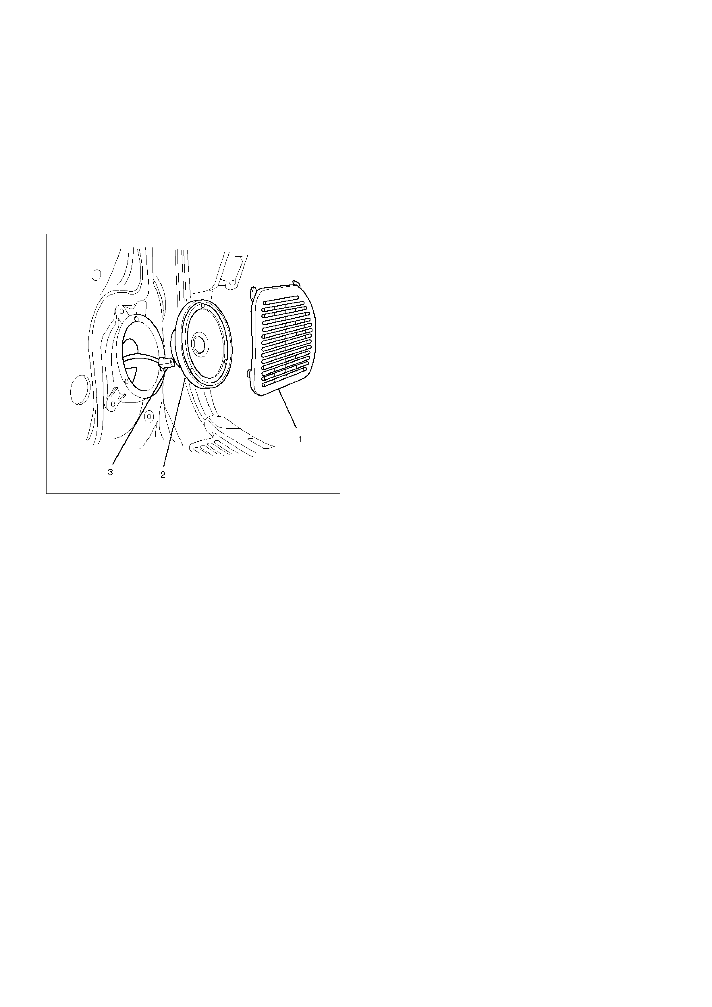
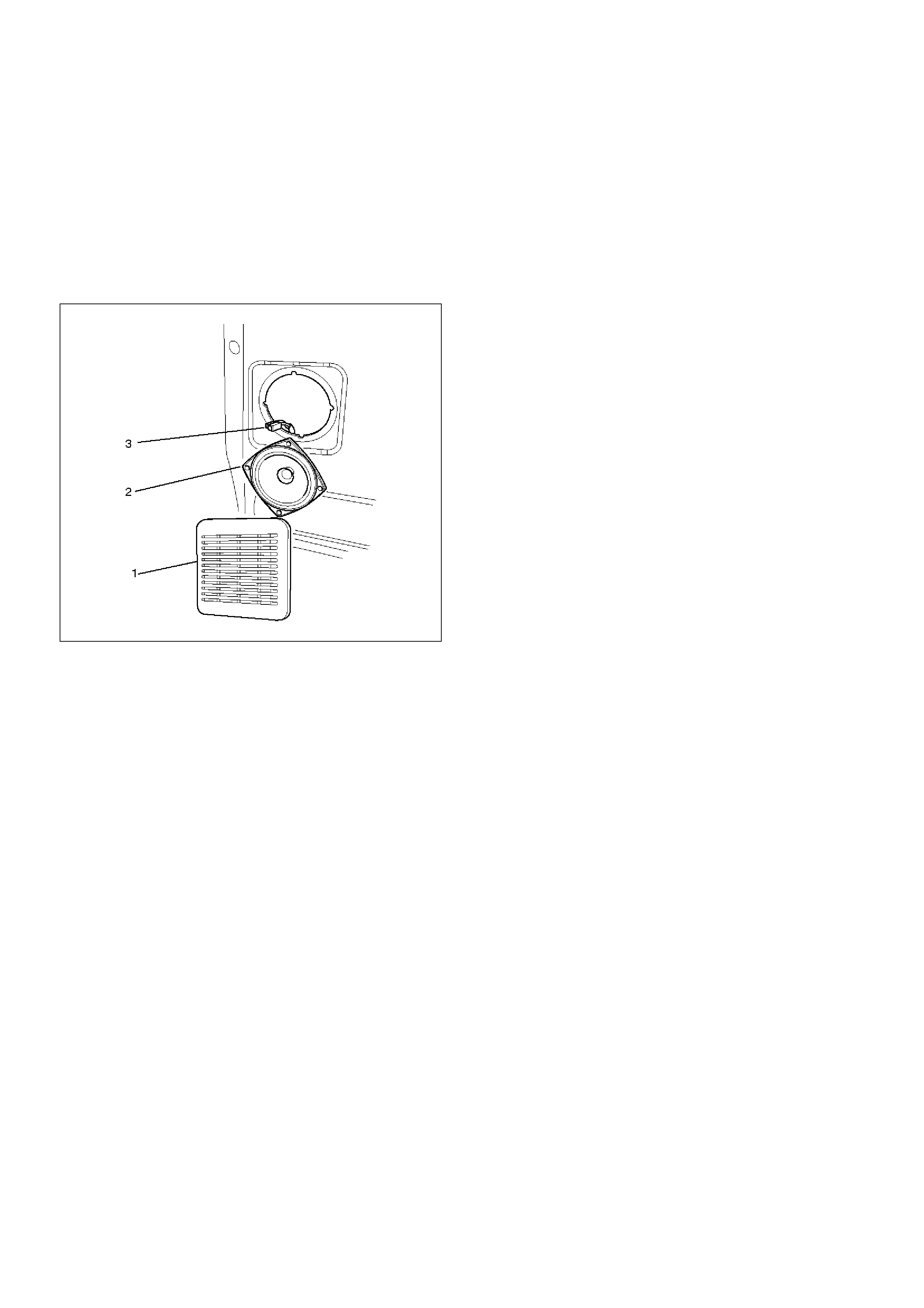
Front Speaker
Removal
1. Disconnect the battery ground cable.
2. Pull the grille(1) to release the locks and then
remove it.
3. Remove four screws and disconnect the
connector(3) to remove the speaker(2).
890RW013
Installation
To install, follow the removal steps in the reverse order.
Rear Speaker
Removal
1. Disconnect the battery ground cable.
2. Pull the grille(1) to release the locks and then
remove it.
3. Remove four screws and disconnect the
connector(3) to remove the speaker(2).
890RW015
Installation
To install, follow the removal steps in the reverse order.