
SECTION 12E - CRUISE CONTROL SYSTEM — OEM
Service Precaution
General Description
Diagnosis
Brake Switch
Removal
Installation
Adjustment
Clutch Switch
Removal and Installation
Adjustment
Starter Switch
Removal
Installation
Cruise Control Main Switch
Removal
Installation
Cruise Control Switch (Combination Switch)
Removal and Installation
Cruise Control Unit
Removal
Installation
Cruise Actuator
Actuator Cable Diagram
Removal
Installation
Mode Switch
Removal and Installation
Service Precaution
WARNING: IF SO EQUIPPED WITH A
SUPPLEMENTAL RESTRAINT SYSTEM (SRS),
REFER TO THE SRS COMPONENT AND WIRING
LOCATION VIEW IN ORDER TO DETERMINE
WHETHER YOU ARE PERFORMING SERVICE ON
OR NEAR THE SRS COMPONENTS OR THE SRS
WIRING. WHEN YOU ARE PERFORMING SERVICE
ON OR NEAR THE SRS COMPONENTS OR THE SRS
WIRING, REFER TO THE SRS SERVICE
INFORMATION. FAILURE TO FOLLOW WARNINGS
COULD RESULT IN POSSIBLE AIR BAG
DEPLOYMENT, PERSONAL INJURY, OR
OTHERWISE UNNEEDED SRS SYSTEM REPAIRS.
CAUTION: Always use the correct fastener in the
proper location. When you replace a fastener, use
ONLY the exact part number for that application.
HOLDEN will call out those fasteners that require a
replacement after removal. HOLDEN will also call
out the fasteners that require thread lockers or
thread sealant. UNLESS OTHERWISE SPECIFIED,
do not use supplemental coatings (Paints, greases,
or other corrosion inhibitors) on threaded fasteners
or fastener joint interfaces. Generally, such
coatings adversely affect the fastener torque and
the joint clamping force, and may damage the
fastener. When you install fasteners, use the correct
tightening sequence and specifications. Following
these instructions can help you avoid damage to
parts and systems.
Techline

General Description
The cruise control keeps the vehicle running at a fixed
speed until a signal canceling this fixed speed is
received .
When the main switch “AUTO CRUISE” is turned on
with the vehicle in the running mode, the battery voltage
is applied to the control unit. When a signal from the
control switch is input to the control unit while the
vehicle is in this state, the cruise control actuator is
activated to operate the system. Also, while the system
is operating, the “AUTO CRUISE” indicator light in the
meter assembly lights up.
1. SET/COAST Switch Function
1.Set Function: When the SET/COAST switch is
pressed and released with the main switch on, the
speed at which the vehicle is running at that
moment is stored in the memory, and the vehicle
automatically runs at the stored speed.
2.Coast-down Function: When the SET/COAST
switch is kept on while the vehicle in running, the
vehicle decelerates during that time. The speed at
which vehicle is running when the control switch is
turned off is stored in the memory, and the vehicle
automatically returns to the stored speed.
3.Tap-down Function: When the SET/COAST switch
is turned on and off instantaneously while the
vehicle is running, the vehicle decelerates a mile for
each on/off operation. The vehicle speed at which
the vehicle was running when the SET/COAST was
turned off last is stored in the memory, and the
vehicle automatically returns to this stored speed.
2. RESUME/ACCEL Switch Function
1.Resume Function: When the RESUME/ACCEL
switch is turned on/off after the system is
temporarily deactivated by pressing the brake or
clutch pedal while the vehicle is running, the vehicle
resumes the speed stored before the system was
released, and the vehicle automatically runs at the
stored speed .
2.Accelerate Function: When the RESUME/ACCEL
switch is kept on after the system is released
completely, the vehicle accelerates its speed during
that time. The vehicle speed at which the vehicle
was running when the switch was turned off is
stored in the memory, and the vehicle automatically
returns to this speed.
3.Tap-up Function: When the RESUME/ACCEL
switch is turned on and off instantaneously while
the vehicle is running, the vehicle decelerates a mile
for each on/off operation. The vehicle speed at
which the vehicle was running when the switch was
turned off last is stored in the memory, and the
vehicle automatically returns to this stored speed.
3. CANCEL Function
1.Temporary Cancellation:
•When the brake pedal is pressed.
•When the clutch pedal is pressed. (M/T)
•When the select lever is shifted to any position
other than“D”, “3”, “2”or“L”. (A/T)
•When the cancel switch is operated.
•When the vehicle speed exceeds about 20 km/h
over the vehicle speed stored in the memory.
•Turning the RESUME/ACCEL switch will return
the vehicle to the speed stored in the cruise
control memory.
2.Complete Cancellation:
•When the starter switch or the main switch is
turned off.
•When the fail-safe function is activated.
•When the vehicle speed is about 38.5 km/h.
Diagnosis
Refer to the Cruise Control System Diagnosis in Wiring
System section.
Brake Switch
Removal
1. Disconnect the battery ground cable.
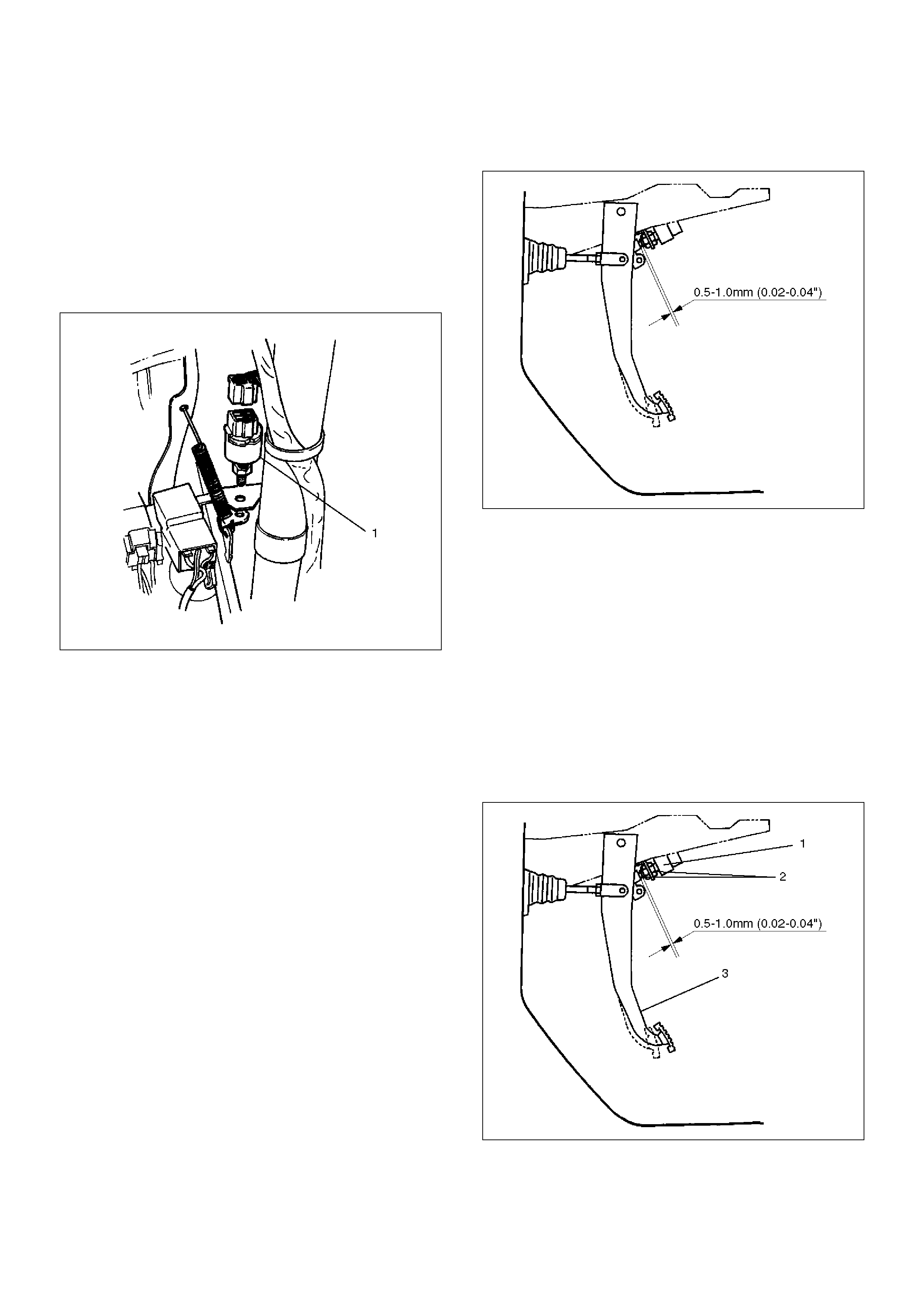
2. Remove the brake switch (1).
• Disconnect the connector.
• Loosen the lock nuts of the switch.
• Remove the switch by turning it.
310RS004
Installation
To install, follow the removal steps in the reverse order,
noting the following points.
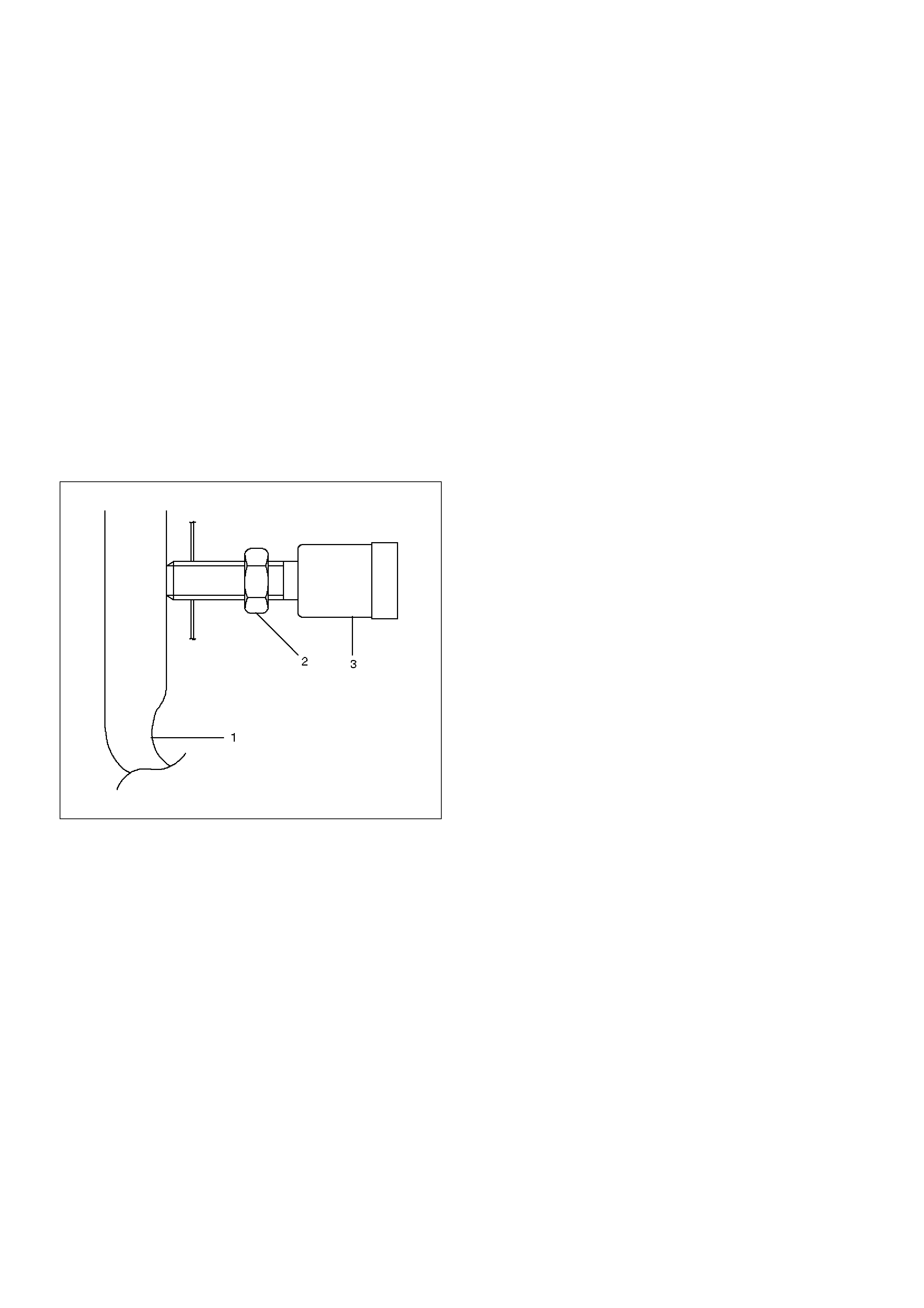
1. Check to see if the brake pedal has been returned
by the return spring to the specified position.
2. Turn the switch clockwise until the tip of the
threaded portion of the brake switch contacts the
pedal arm.
3. Turn the switch counterclockwise until the space
between the tip of the threaded portion and the
pedal arm is 0.5 to 1.0 mm (0.02-0.04 in.) as shown
in the figure.
310RS003
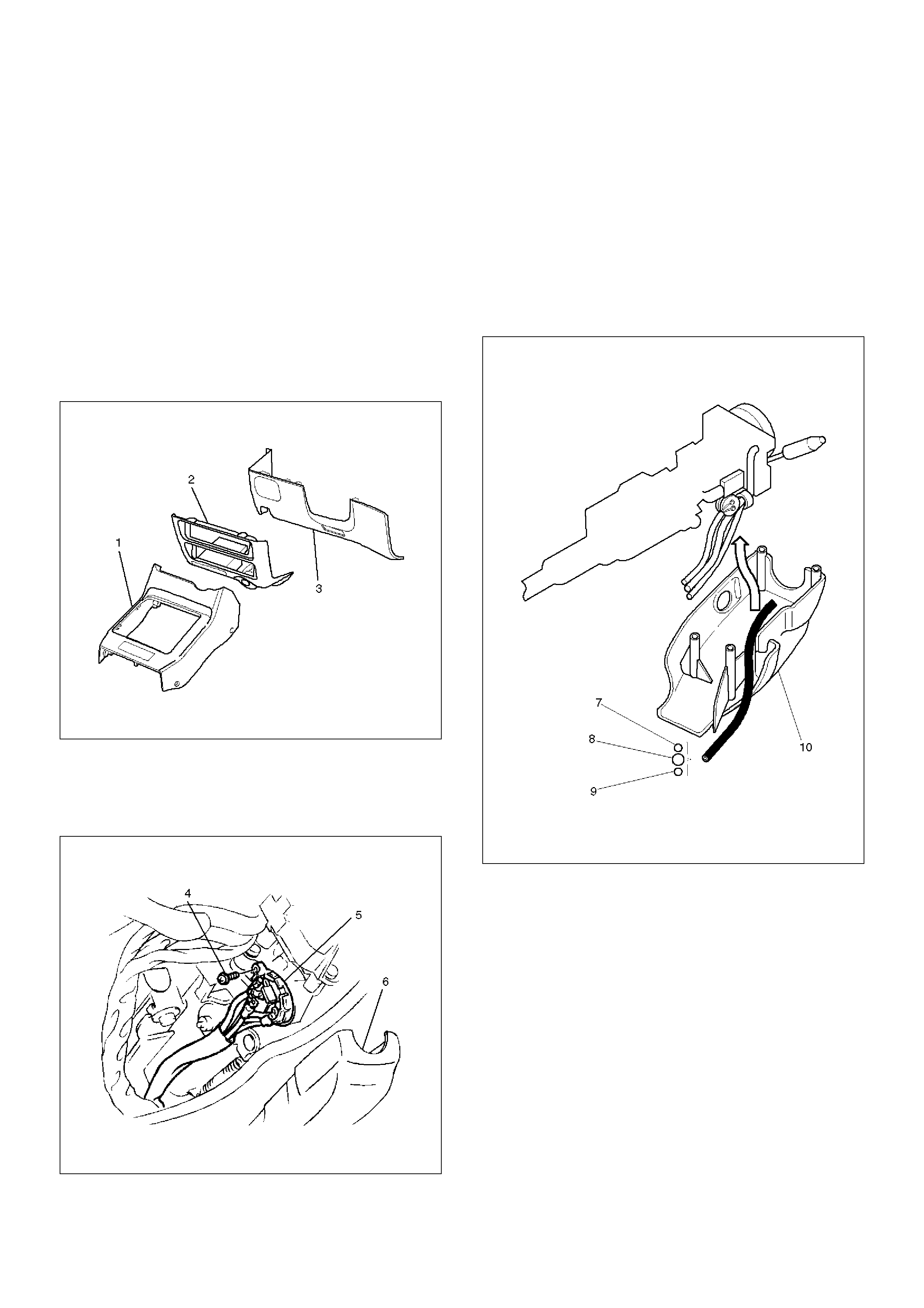
Adjustment
1. Check to be sure that the brake pedal (3) has been
completely returned by the return spring.
2. Disconnect the switch connector.
3. Loosen the lock nut (1) of the switch (2).
4. Turn the switch clockwise until the tip of screw
portion of the brake pedal hits the pedal arm.
5. Turn the switch counterclockwise until the clearance
between the tip of the screw portion and the pedal
arm becomes 0.5 to 1.0 mm (0.02-0.04 in).
6. Tighten the lock nut.
7. Connect the switch connector.
310RW006
Clutch Switch
Removal and Installation
Refer to the Clutch Control removal and installation
steps in Clutch section.
Adjustment
1. Check to be sure that the clutch pedal (1) has been
completely returned by the return spring.
2. Disconnect the switch connector.
3. Loosen the lock nut (2) of the switch (3).
4. Push the switch by hand until the push rod cannot
be seen from the tip portion of the switch.
5. Give the switch one reverse rotation.
6. Tighten the lock nut.
7. Connect the switch connector.
203RW002
Starter Switch
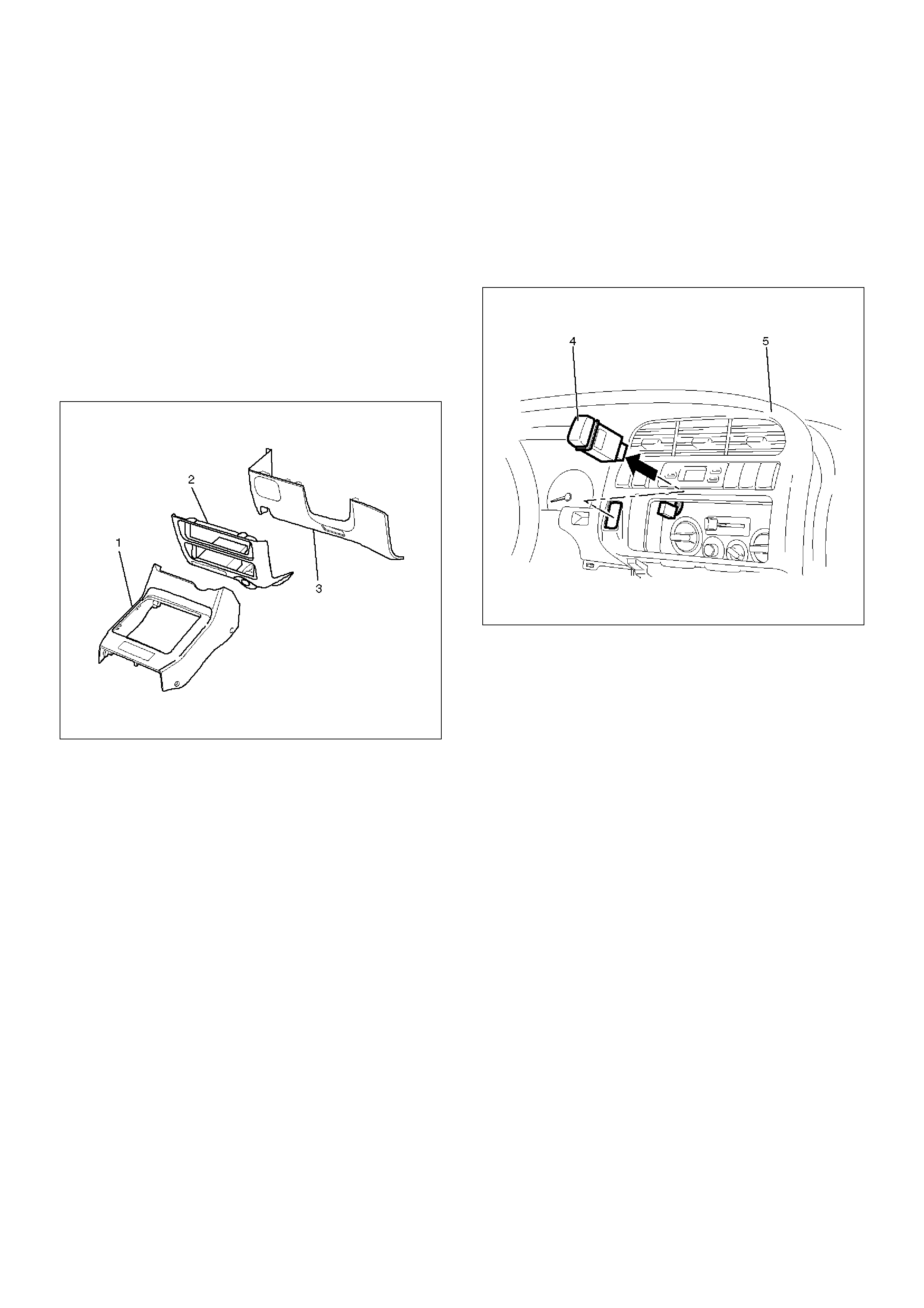
Removal
1.Disconnect the battery ground cable.
2.Remove the front console assembly (1). Refer to
the Instrument Panel Assembly in Body Structure
section.
3. Remove the lower cluster assembly (2). Refer to
the Instrument Panel Assembly in Body Structure
section.
4. Remove the instrument panel driver lower cover
assembly (3). Refer to the Instrument Panel
Assembly in Body Structure section.
821RW024
5. Remove seven screws to remove the steering cowl
(6).
6. Disconnect the connector, remove the screw (4) and
then remove the starter switch (5).
431RW005
Installation
To install, follow the removal steps in the reverse order,
noting the following point.
1. When installing the steering cowl (10), be sure to
pass the harnesses through the route as shown in
the figure so that the starter switch harness (7), the
combination switch harness (8) and the inflator
module harness (9) will not catch.
825RW058
Cruise Control Main Switch
Removal
1.Disconnect the battery ground cable.
2.Remove the front console assembly (1). Refer to
the Instrument Panel Assembly in Body Structure
section.
3.Remove the lower cluster assembly (2). Refer to the
Instrument Panel Assembly in Body Structure
section.
4.Remove the instrument panel driver lower cover
assembly (3). Refer to the Instrument Panel
Assembly in Body Structure section.
821RW024
5.Remove the instrument panel cluster assembly (5).
Refer to the Instrument Panel Assembly in Body
Structure section.
6.Disconnect the and push the lock from the side of
the instrument panel cluster assembly to remove the
cruise control main switch (4).
821RW079
Installation
To install, follow the removal steps in the reverse order,
noting the following point.
1.Push in the switch with your fingers until the switch
is locked securely.
Cruise Control Switch (Combination Switch)
Removal and Installation
Refer to the Lighting Switch (Combination Switch)
removal and installation steps of Lighting System in
Body and Accessories section.
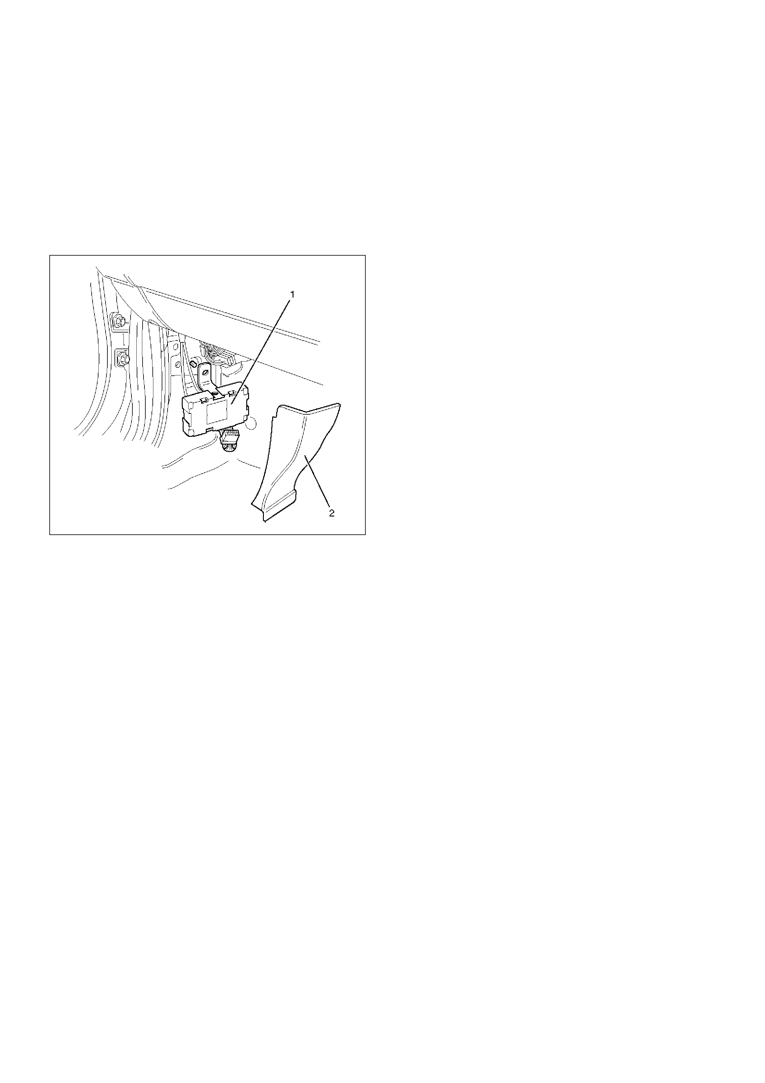
Cruise Control Unit
Removal
1. Disconnect the battery ground cable.
2. Remove the dash side trim panel (RH)(2).
3. Disconnect the connector.
4. Remove a fixing nut to remove the cruise control
unit (1).
825RW050
Installation
To install, follow the removal steps in the reverse order.
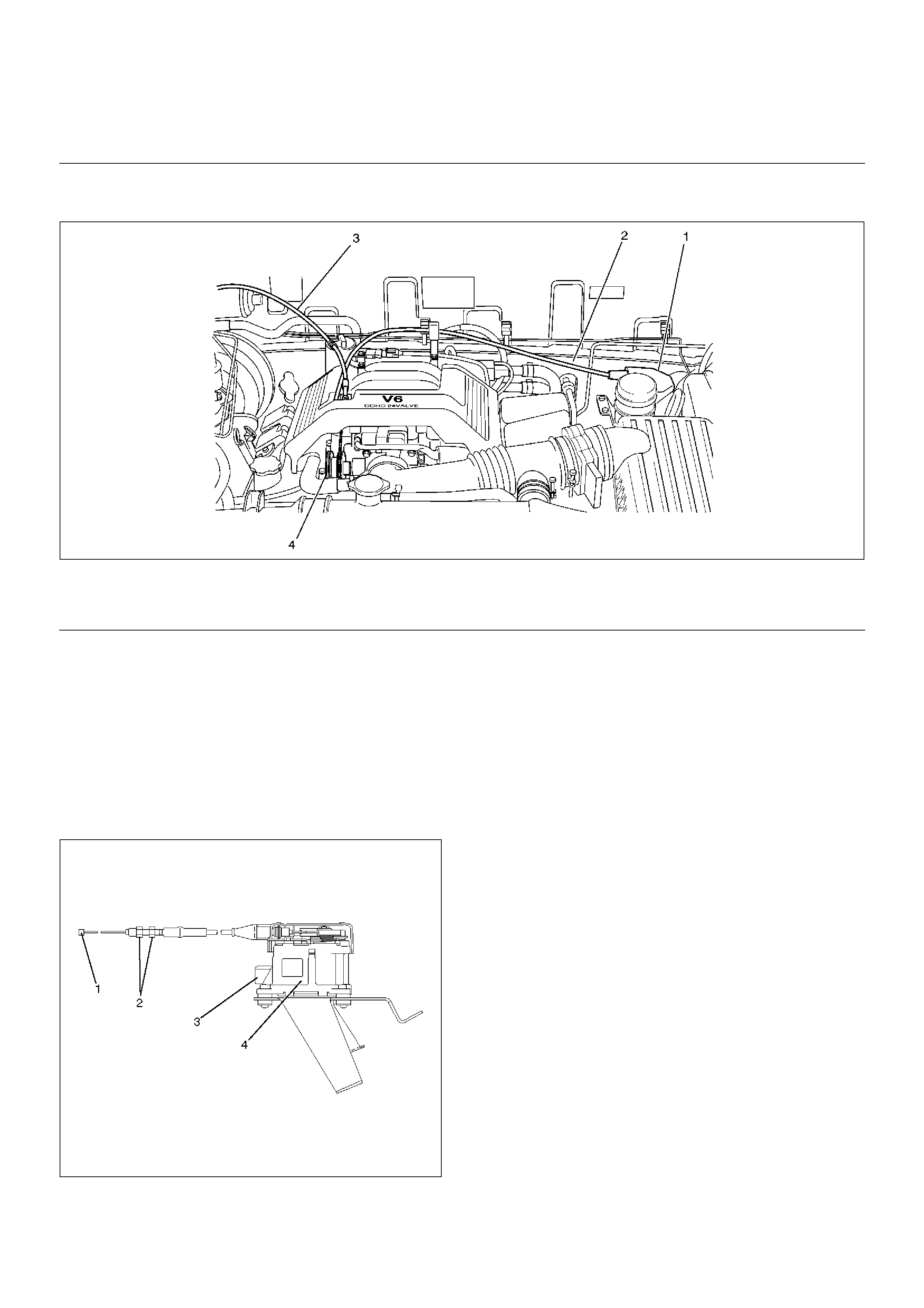
Cruise Actuator
EndOFCallout
Actuator Cable Diagram
825RW221
EndOFCallout
Removal
1. Disconnect the battery ground cable.
2. Remove the cruise actuator Assembly (4).
• Disconnect the connector (3).
• Remove the cable end (1) from the cam link
(cruise control side).
• Loosen two fixing nuts (2).
• Remove three actuator fixing screws.
825RW049
Installation
To install, follow the removal steps in the reverse order,
noting the following point.
1. Take care not to bend the cable excessively.
Legend
(1) Cruise Actuator Assembly
(2) Cruise Control Cable
(3) Accel Control Cable
(4) Cam Link (Cruise Control Side)
