
SECTION 12F - WIPER / WASHER SYSTEM
Service Precaution
Windshield Wiper/Washer System
General Description
Windshield Wiper And Washer Switch
Removal and Installation
Windshield Wiper Motor
Removal
Installation
Windshield Washer Motor
Removal
Installation
Windshield Wiper Linkage
Windshield Wiper Linkage and Associated Parts
Removal
Installation
Windshield Wiper Arm/Blade
Removal
Installation
Windshield Wiper Blade Rubber
Removal
Installation
Rear Wiper/Washer System
General Description
Rear Wiper and Washer Switch
Removal
Installation
Rear Wiper Motor
Removal
Installation
Alarm & Relay Control Unit
Removal
Installation
Rear Washer Motor
Removal
Installation
Rear Wiper Arm/Blade
Removal
Installation
Rear Washer Nozzle
Removal
Installation
Rear Washer Nozzle Angle Adjustment
Rear Wiper Blade Rubber
Removal and Installation
Headlamp Wiper/Washer
General Description
Headlamp Wiper and Washer Switch
Removal
Installation
Headlamp Wiper Arm & Blade
Removal
Installation
Headlamp Wiper Motor
Removal
Installation
Headlamp Washer Motor
Removal and Installation
Main Data and Specifications
Service Precaution
WARNING: IF SO EQUIPPED WITH A
SUPPLEMENTAL RESTRAINT SYSTEM (SRS),
REFER TO THE SRS COMPONENT AND WIRING
LOCATION VIEW IN ORDER TO DETERMINE
WHETHER YOU ARE PERFORMING SERVICE ON
OR NEAR THE SRS COMPONENTS OR THE SRS
WIRING. WHEN YOU ARE PERFORMING SERVICE
ON OR NEAR THE SRS COMPONENTS OR THE SRS
WIRING, REFER TO THE SRS SERVICE
INFORMATION. FAILURE TO FOLLOW WARNINGS
COULD RESULT IN POSSIBLE AIR BAG
DEPLOYMENT, PERSONAL INJURY, OR
OTHERWISE UNNEEDED SRS SYSTEM REPAIRS.
CAUTION: Always use the correct fastener in the
proper location. When you replace a fastener, use
ONLY the exact part number for that application.
HOLDEN will call out those fasteners that require a
replacement after removal. HOLDEN will also call
out the fasteners that require thread lockers or
thread sealant. UNLESS OTHERWISE SPECIFIED,
do not use supplemental coatings (Paints, greases,
or other corrosion inhibitors) on threaded fasteners
or fastener joint interfaces. Generally, such
coatings adversely affect the fastener torque and
the joint clamping force, and may damage the
fastener. When you install fasteners, use the correct
tightening sequence and specifications. Following
these instructions can help you avoid damage to
parts and systems.
Windshield Wiper/Washer System
General Description
The circuit consists of the starter switch, windshield
wiper & washer switch, windshield wiper motor,
windshield washer motor and windshield intermittent
relay.
When the wiper & washer switch is turned on with the
starter switch on, the battery voltage is applied to the
wiper motor to activate the wiper.
The washer motor squirts glass cleaning fluid while the
washer switch is being pushed. The intermittent relay is
used to control motion of the wiper.
Windshield Wiper And Washer Switch
Removal and Installation
Refer to the Lighting Switch (Combination Switch) in
Lighting System section.
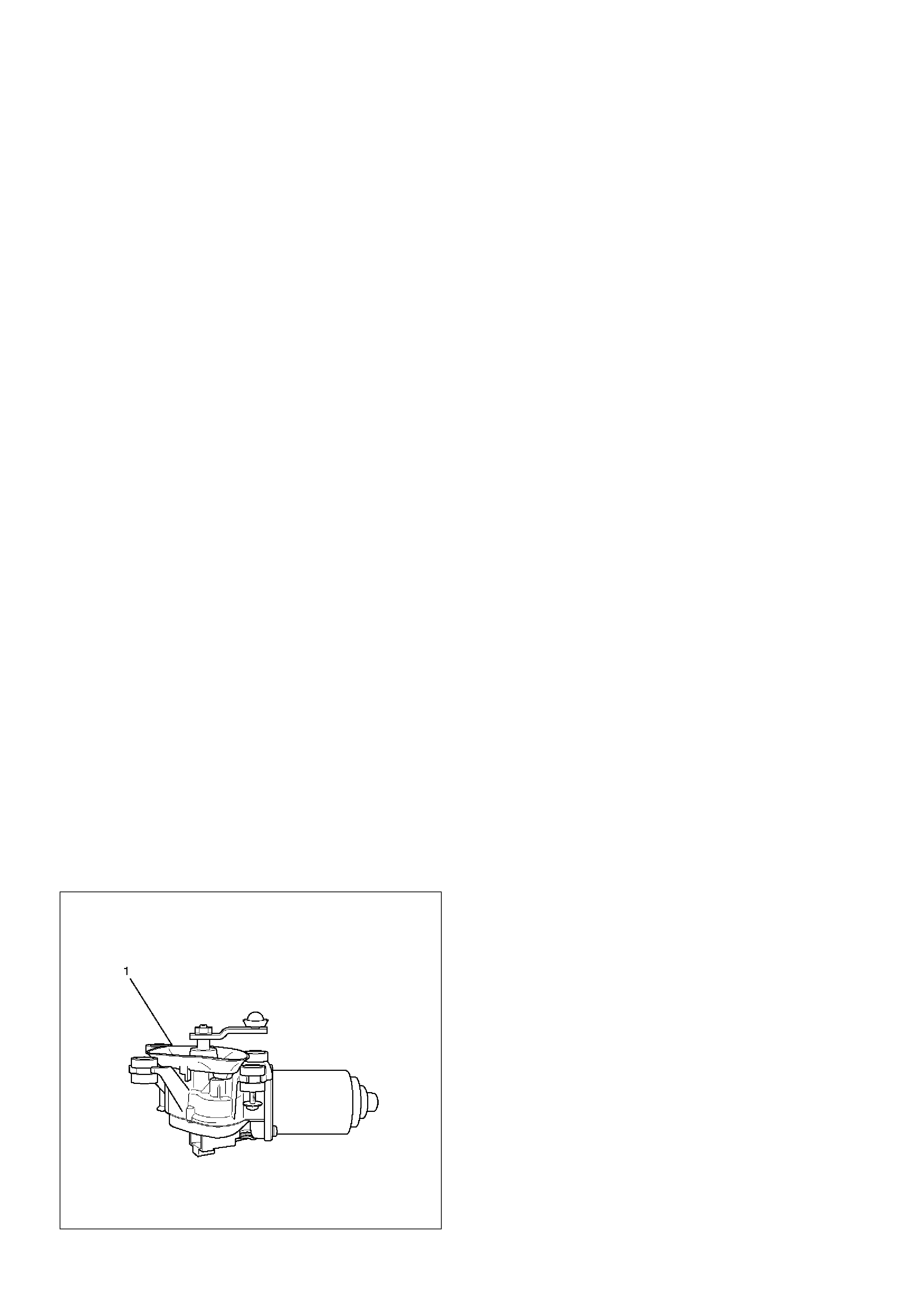
Windshield Wiper Motor
Removal
1. Disconnect the battery ground cable.
2. Disconnect the connector.
3. Remove 4 mounting bolts.
4. Remove the windshield wiper motor(1).
880RW007
Installation
To install, follow the removal steps in the reverse order.
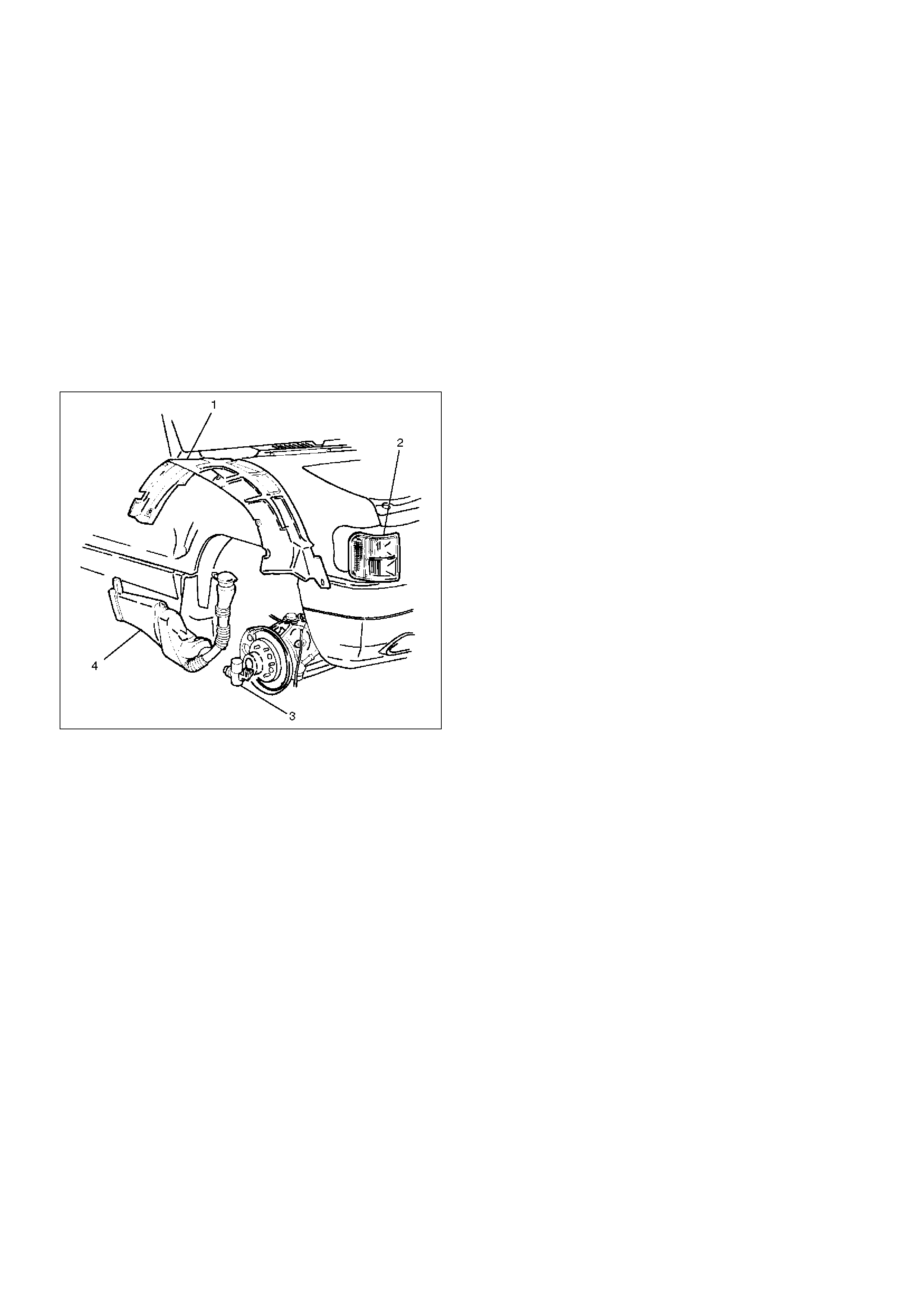
Windshield Washer Motor
Removal
1. Disconnect the battery ground cable.
2. Remove the fender inner liner (right side) (1).
3. Remove the screws and then remove the front
combination light(2).
4. Remove 2 screws, the filler neck and the hose.
5. Disconnect the windshield washer motor connector
and remove the washer tank (4).
6. Pull the windshield washer motor(3) from the
washer tank(4).
880RS006
Installation
To install, follow the removal steps in the reverse order.
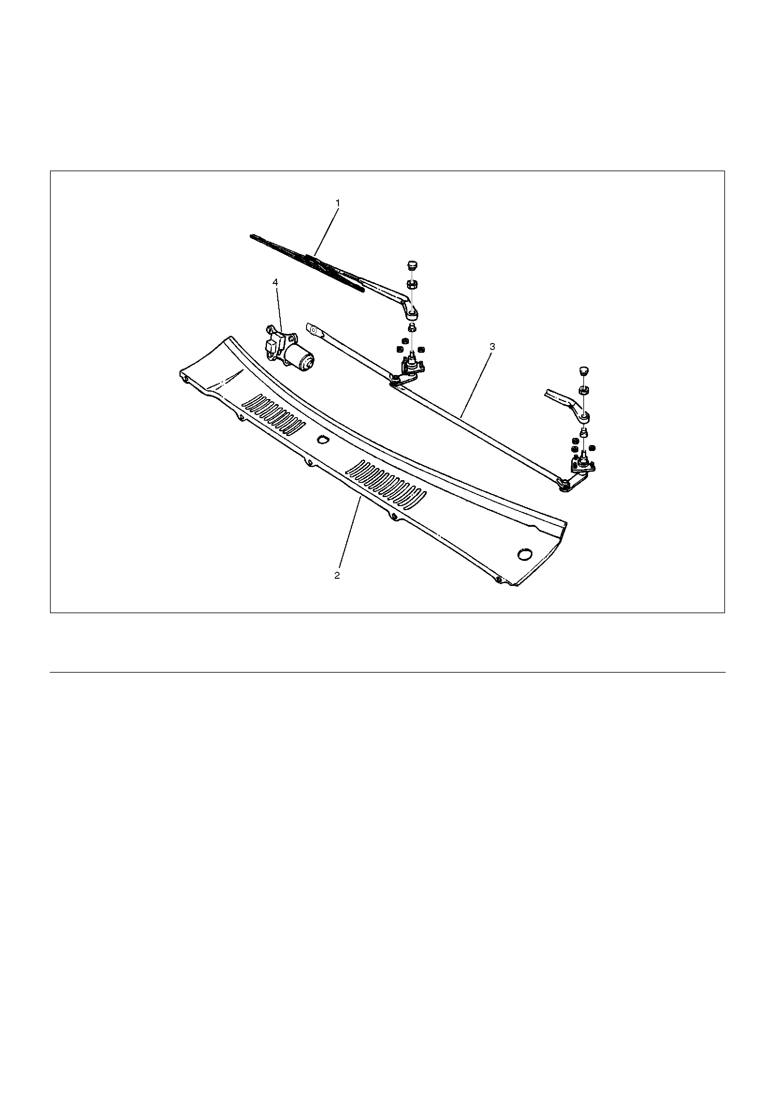
Windshield Wiper Linkage
Windshield Wiper Linkage and Associated Parts
880RW008
EndOFCallout
Removal
1. Disconnect the battery ground cable.
2. Remove the windshield wiper arm/blade.
3. Remove the windshield wiper motor.
4. Remove the pivot assembly mounting nuts, fixing
screws and then remove the vent cowl cover.
5. Take out the windshield wiper linkage assembly
from the opening of the cowl.
Installation
To install, follow the removal steps in the reverse order.
Legend
(1) Windshield Wiper Arm/Blade
(2) Vent Cowl Cover
(3) Windshield Wiper Linkage Assembly
(4) Windshield Wiper Motor
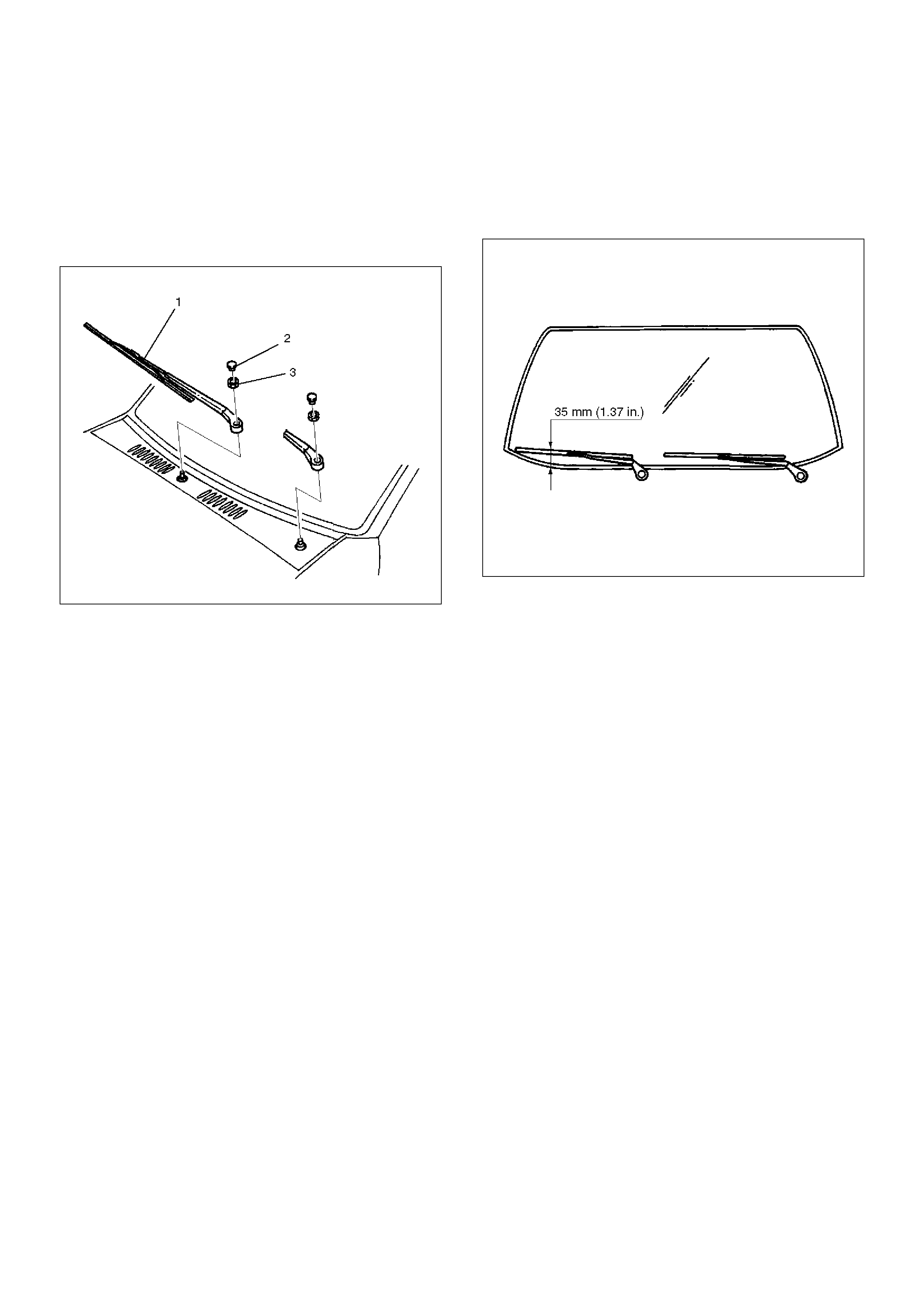
Windshield Wiper Arm/Blade
Removal
1. Pry the cap(2) off with the tip of a screwdriver.
2. Remove the nut(3).
3. Remove the wiper/blade(1).
880RS005
Installation
To install, follow the removal steps in the reverse order,
noting the following points.
880RS004
1. Wiper arm/blade
• Before installing the wiper arm/blade to the shaft,
confirm that the motor stops at the auto-stop
position.
• Set the wiper arm/blade so that the tips of both
blades are positioned about 35mm (1.37in) from
the upper edge of the cowl cover as shown in the
figure.
• Tighten the nuts to the specified torque.
Torque: 31N·m (3.2 kg·m/23lbft)
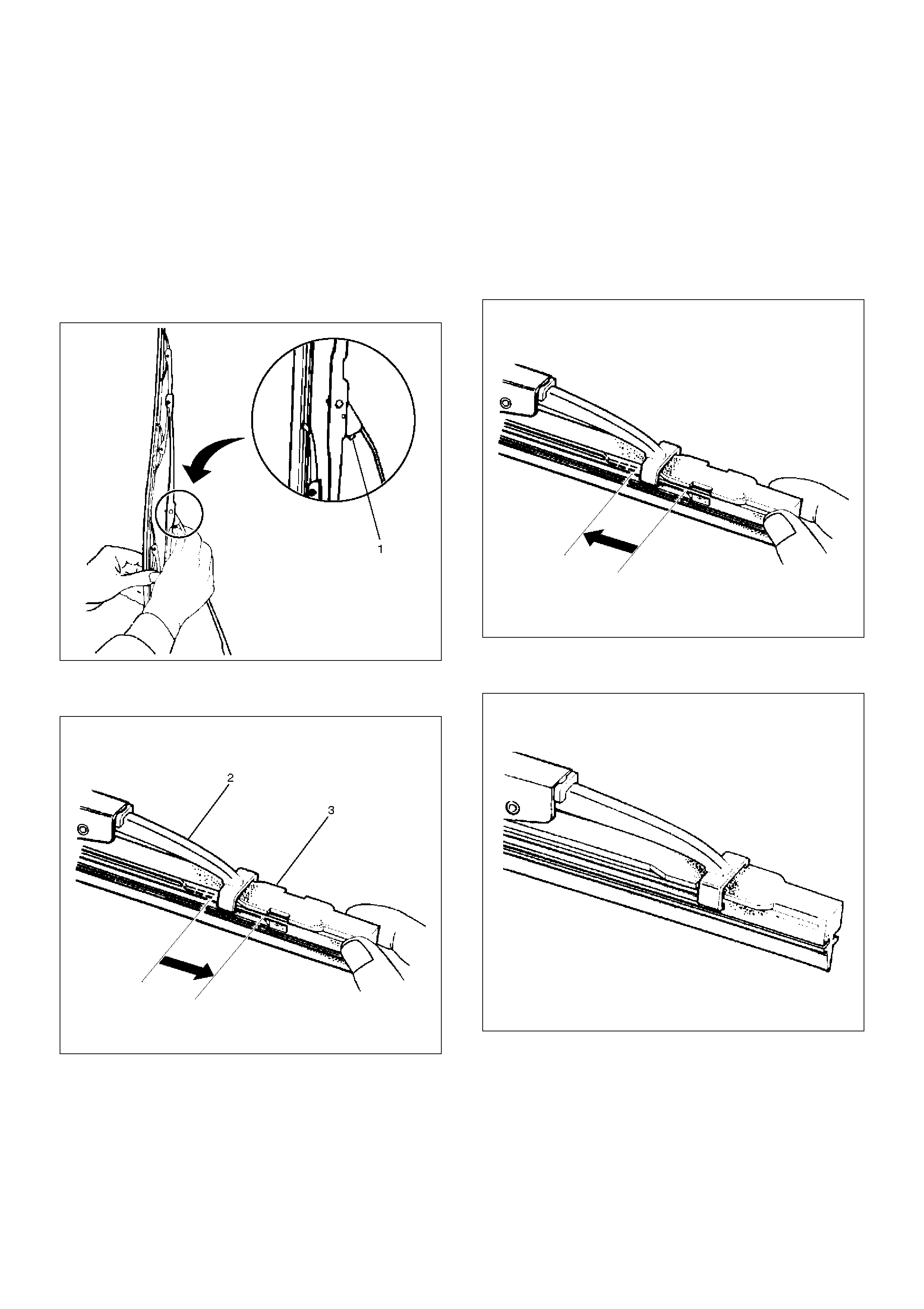
Windshield Wiper Blade Rubber
Removal
1. Push the wiper blade lock(1) while pulling the wiper
blade in the arrow direction as shown in the figure.
CAUTION: When the wiper blade has been
removed, wrap the tip of the wiper arm with cloth, to
avoid damaging the glass.
CAUTION:
880RS011
2. Pull the end of rubber and remove the projection(3)
from the click of the blade stay (2).
880RS010
3. Pull the rubber out in the same direction.
Installation
To install, follow the removal steps in the reverse order,
noting the following points.
1. Install the click of the blade stay in the groove of the
new rubber and slide it in. Complete wiper blade
installation by pushing the click.
885RS002
2. Finally, check that the click of the stay has caught in
the hole of the rubber.
885RS001
Rear Wiper/Washer System
General Description
The circuit consists of the starter switch, rear wiper &
washer switch, rear wiper motor, rear washer motor and
rear intermittent relay.
When the wiper & washer switch is turned on with the
starter switch on, the battery voltage is applied to the
wiper motor to activate the wiper.
The washer motor squirts glass cleaning fluid while the
washer switch is being pushed. The intermittent relay is
used to control motion of the wiper.
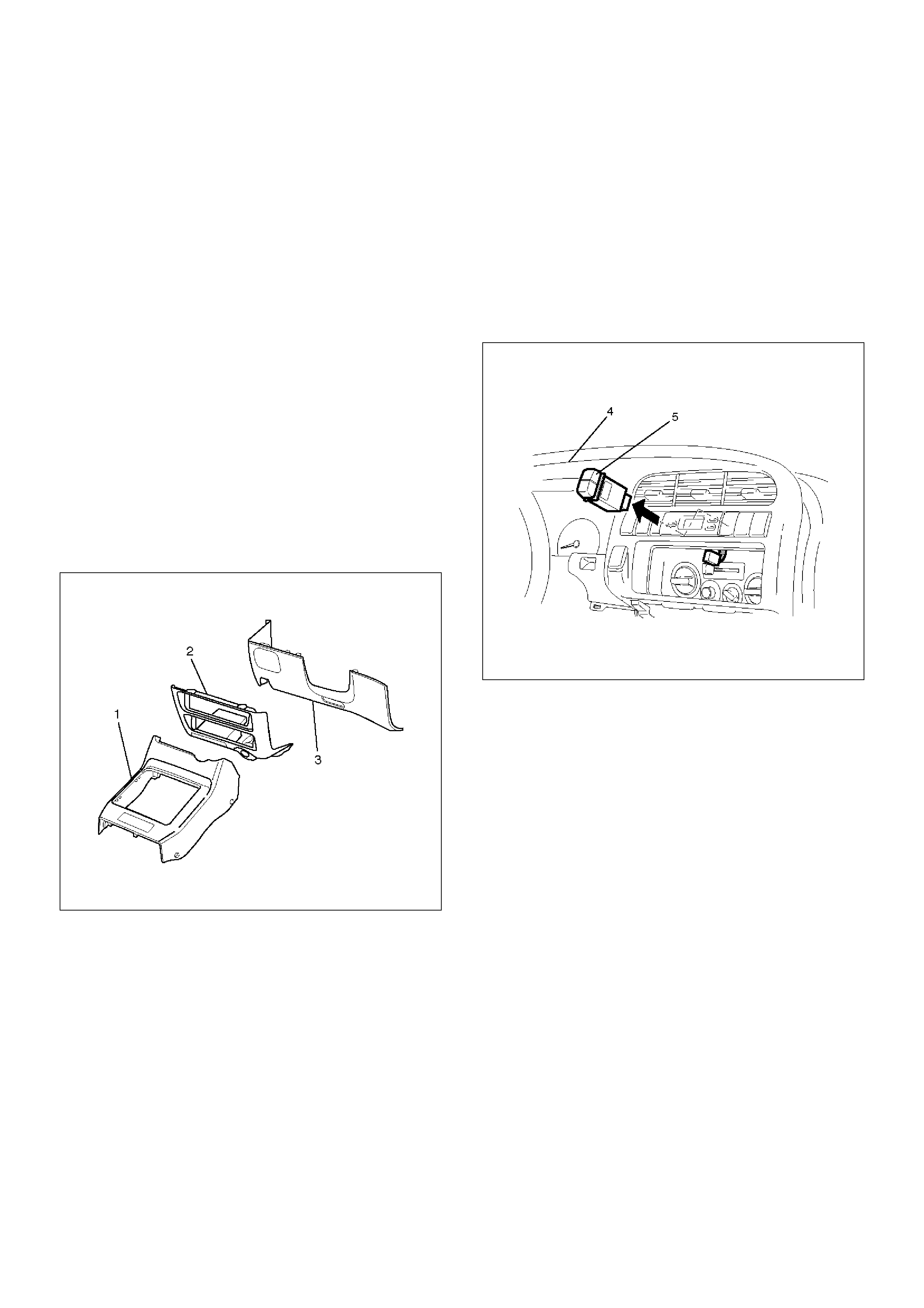
Rear Wiper and Washer Switch
Removal
1. Disconnect the battery ground cable.
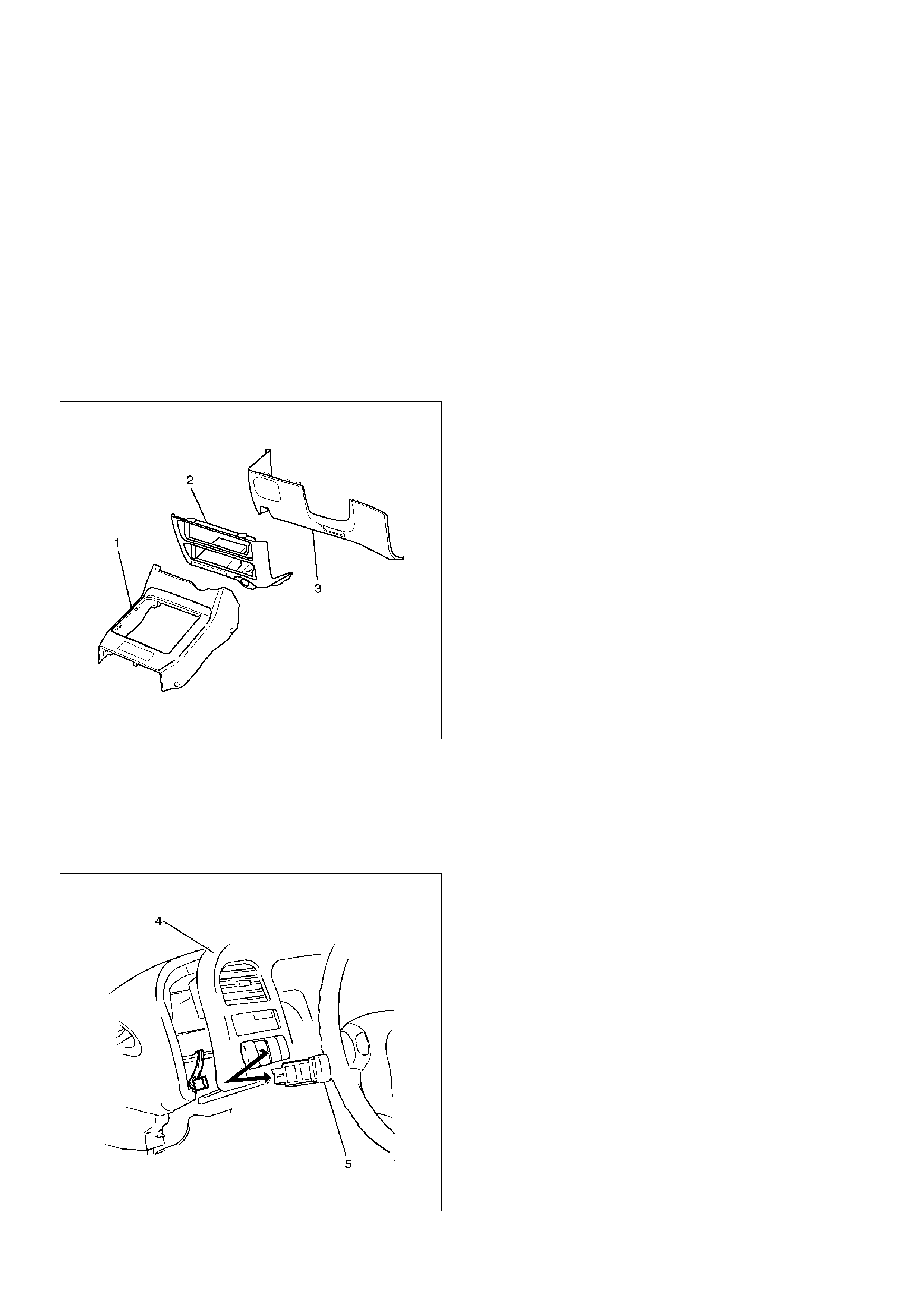
2. Remove the front console assembly(1).
Refer to the Instrument Panel Assembly in Body
Structure section.
3. Remove the lower cluster assembly(2).
Refer to the Instrument Panel Assembly in Body
Structure section.
4. Remove the instrument panel driver lower cover(3).
Refer to the Instrument Panel Assembly in Body
Structure section.
821RW024
5. Remove the instrument panel cluster assembly(4).
Refer to the Instrument Panel Assembly in Body
Structure section.
6. Disconnect the connector and push the lock from
the back side of the instrument panel cluster
assembly to remove the rear wiper & washer
switch(5).
821RW023
Installation
To install, follow the removal steps in the reverse order,
noting the following point:
1. Push the switch with your fingers until it locks
securely.
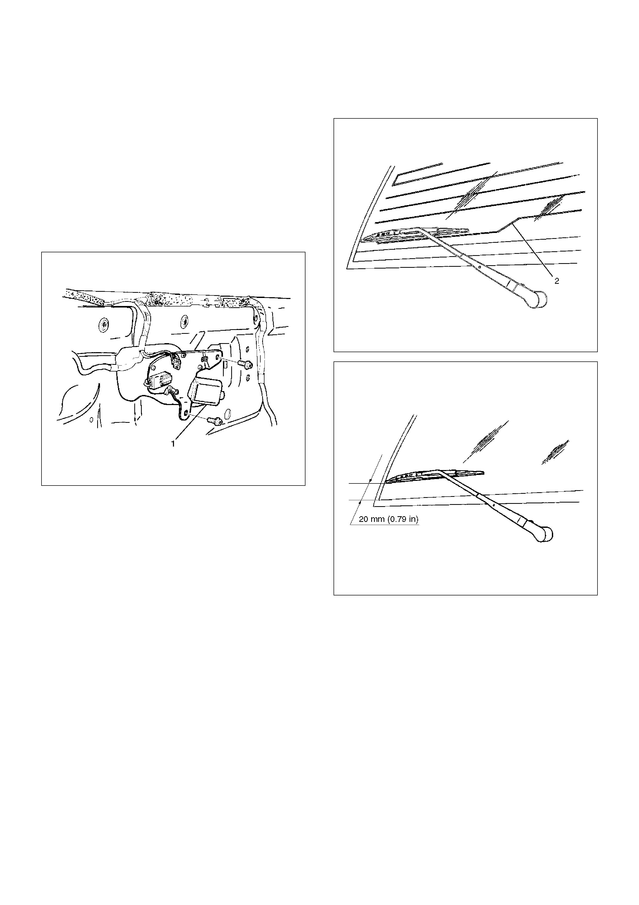
Rear Wiper Motor
Removal
1.Disconnect the battery ground cable.
2.Remove the tailgate trim pad.
3.Remove the wiper arm/blade.
Refer to the removal steps of the Rear Wiper Arm/
Blade in this section.
4. Disconnect the connector remove the wiper shaft
nut, remove the fixing screws and then remove the
rear wiper motor(1).
885RS013
Installation
To install, follow the removal steps in the reverse order,
noting the following points.
1. Before installing the wiper arm/blade to the motor
shaft, confirm that the motor stops at the auto-stop
position.
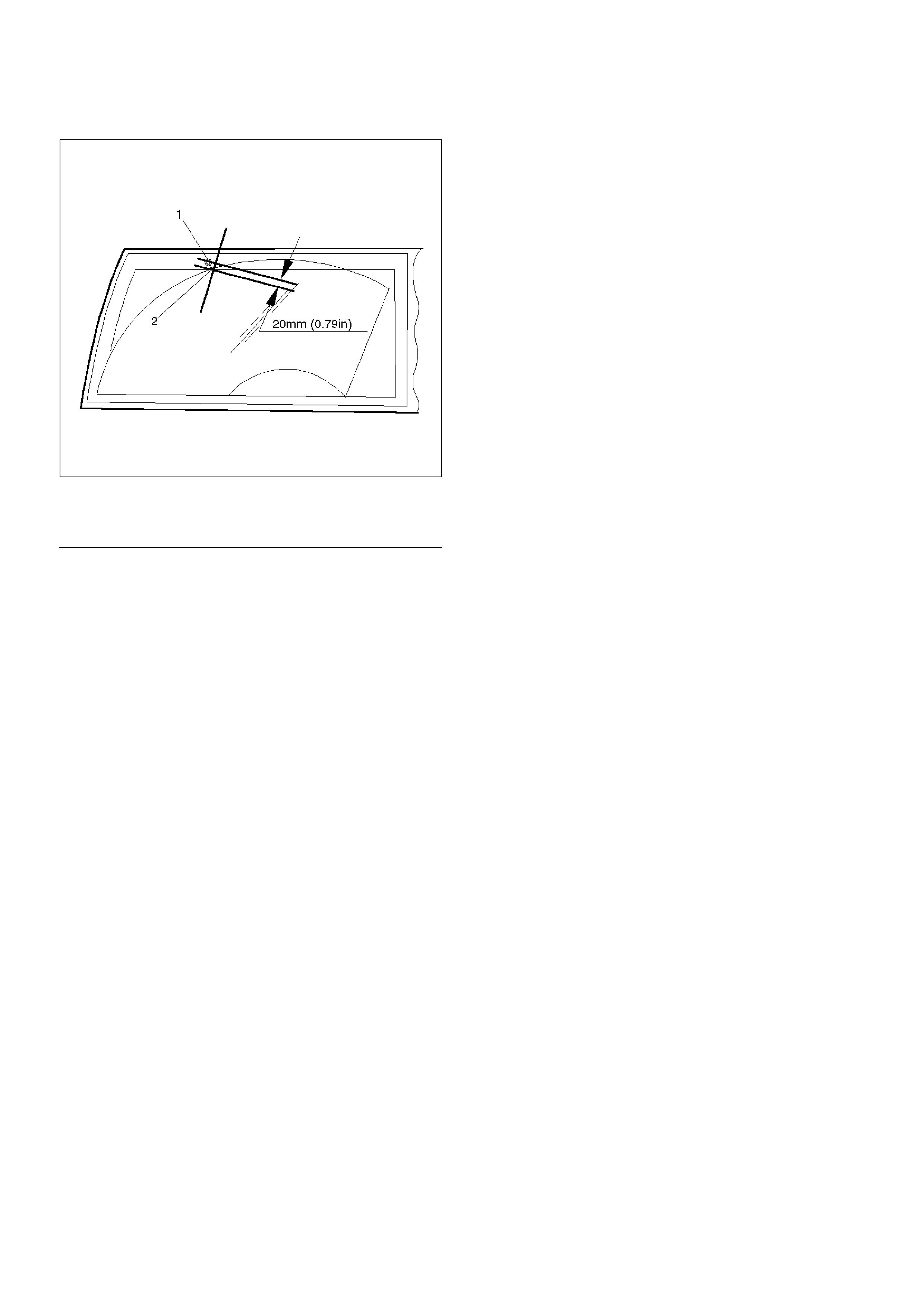
2. Install the wiper arm so that the blade gets parallel
to the lowermost heat wire(2) of the rear defogger
(w/rear defogger), or position the blade 20mm
(0.79in) from edge of tailgate glass (W/O rear
defogger).
885RS012
885RS011
3. Tighten the motor shaft nut to the specified torque.
Torque: 6N·m (0.6 kg·m/52lbin)
4. Tighten the wiper arm nut to the specified torque.
Torque: 9N·m (0.9 kg·m/78lbin)

Alarm & Relay Control Unit
Removal
1. Disconnect the battery ground cable.
2. Remove the glove box.
3. Remove the instrument panel passenger lower
cover assembly.
4. Remove the passenger Knee bolster reinforcement
assembly.
5. Remove the fixing bolts, disconnect the connectors
and then remove the alarm & relay control unit (1).
826RW020
Installation
To install, follow the removal steps in the reverse order.
Rear Washer Motor
Removal
1. Disconnect the battery ground cable.
2. Remove the tailgate trim pad(2).
3. Remove two screws, disconnect the connector,
remove the washer hose and then remove the rear
washer tank(3).
4. Pull out the rear washer motor(1) from the washer
tank.
885RS009
Installation
To install, follow the removal steps in the reverse order.
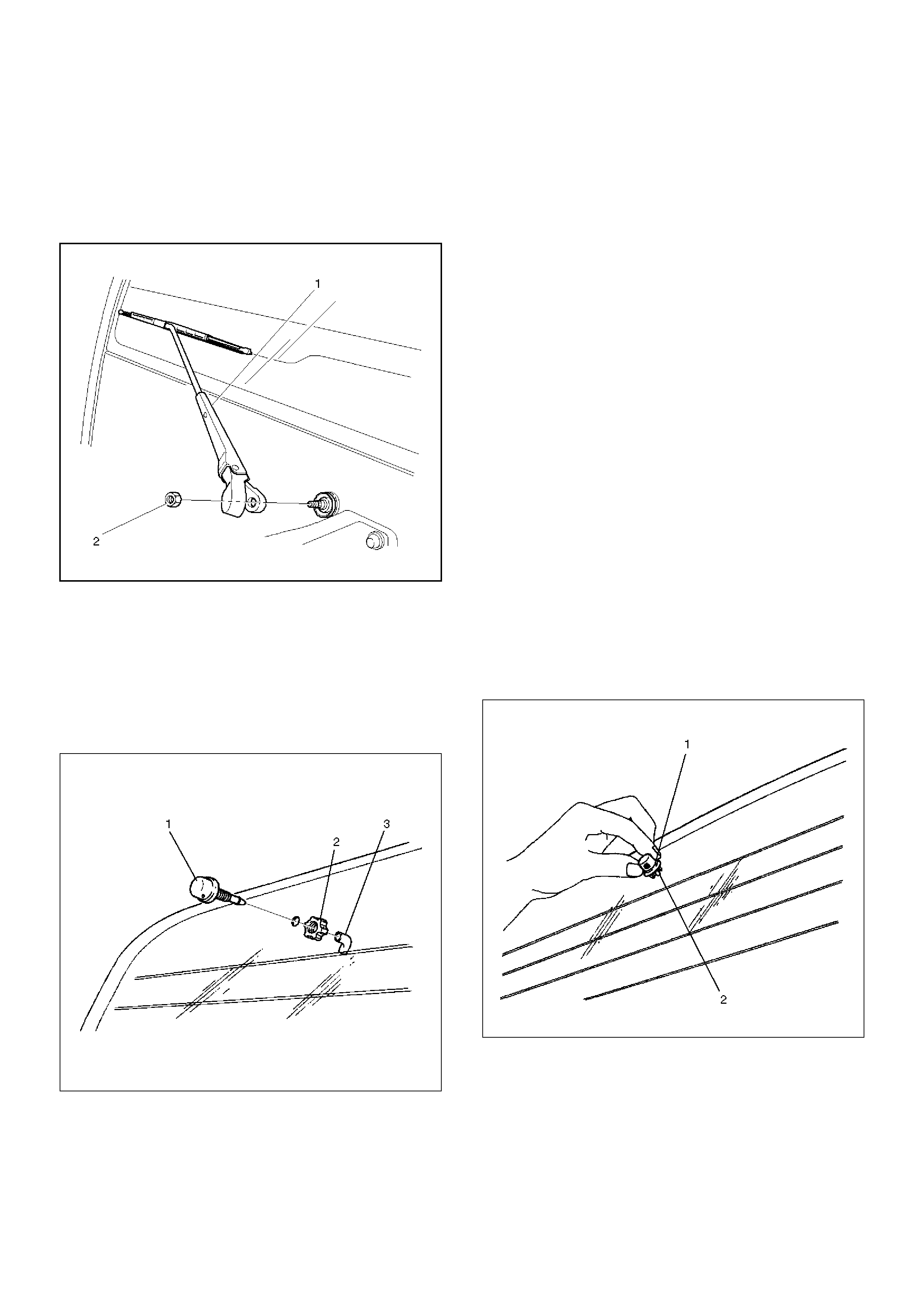
Rear Wiper Arm/Blade
Removal
1. Remove the arm nut(2).
2. Remove the wiper arm/blade(1).
885RS008
Installation
Refer to the installation steps of the Rear Wiper Motor
in Wiper/Washer System section.
Rear Washer Nozzle
Removal
1. Disconnect the hose(3).
2. Remove the lock nut(2), and then remove the
washer nozzle(1).
885RS005
Installation
To install, follow the removal steps in the reverse order.
Rear Washer Nozzle Angle Adjustment
Loosen the lock nut(2) of the washer nozzle(1) to adjust
the injection angle of the cleaning fluid, and then
retighten the lock nut(2).
885RS004
Rear Washer Spray Pattern
885RS003
EndOFCallout
Rear Wiper Blade Rubber
Removal and Installation
Refer to the Windshield Wiper Blade Rubber in this
section.
Headlamp Wiper/Washer
General Description
The circuit consists of the starter switch, headlight
wiper/washer switch, headlight wiper motor and washer
motor. By pushing the headlight wiper/washer switch
with the starter switch on, the wiper will make 5 strokes
with washer solution applied between each of the first 4
strokes, regardless of the length of time the switch is
held down.
The washer nozzle is installed to the wiper blade, and
the tank to which the washer motor is installed shared
among the headlight washer and the windshield washer.
Legend
(1) Washer Nozzle
(2) Spray Target
Headlamp Wiper and Washer Switch
Removal
1.Disconnect the battery ground cable.
2.Remove the front console assembly(1).
Refer to the Instrument Panel Assembly in Body
Structure section.
3.Remove the lower cluster assembly(2).
Refer to the Instrument Panel Assembly in Body
Structure section.
4.Remove the instrument panel driver lower cover(3).
Refer to the Instrument Panel Assembly in Body
Structure section.
821RW024
5.Remove the instrument panel cluster assembly(4).
Refer to the Instrument Panel Assembly in Body
Structure section.
6. Disconnect the connector and push the lock from
the back side of the instrument panel cluster
assembly to remove the headlight wiper switch(5).
825RW245
Installation
To install, follow the removal steps in the reverse order,
noting the following point:
1. Push the switch with your fingers until it locks
securely.
Headlamp Wiper Arm & Blade
Removal
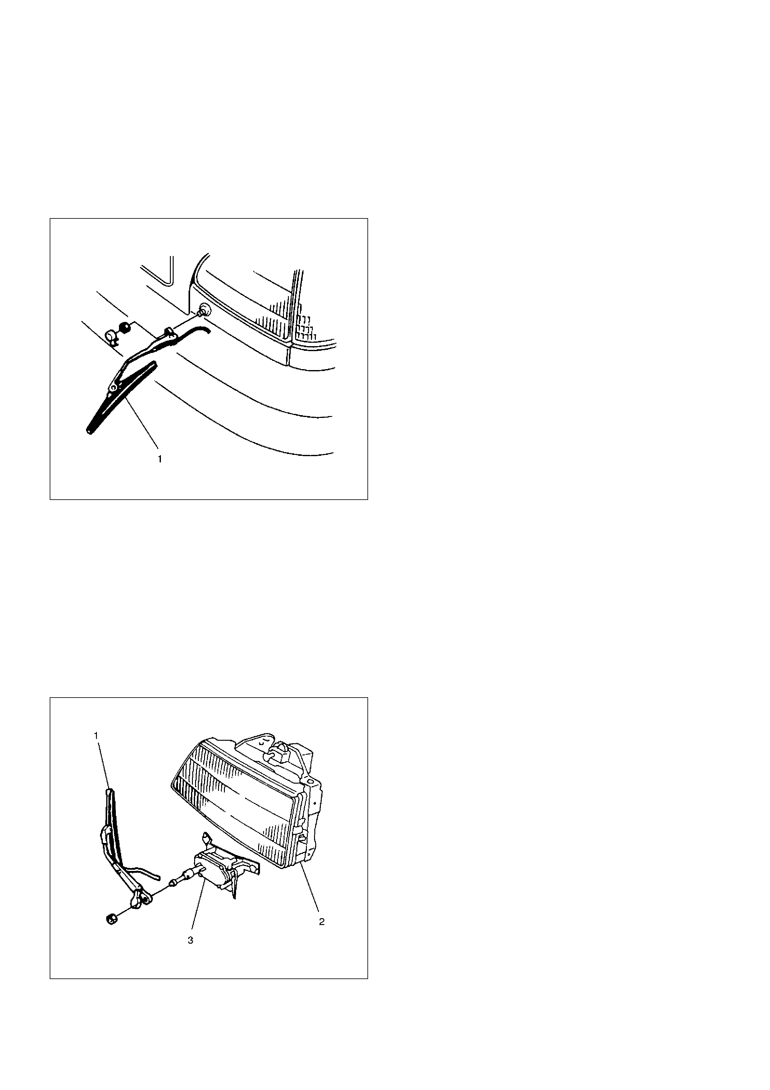
1.Remove the wiper arm nut and the wiper arm &
blade(1).
2.Disconnect the washer hose.
808RW001
Installation
To install, follow the removal steps in the reverse order,
noting the following point:
1.Tighten the wiper arm nut to the specified torque.
Torque: 5N·m(0.5 kg·m/44Ibft)
Headlamp Wiper Motor
Removal
1.Disconnect the battery ground cable.
2.Remove the headlight wiper arm/blade(1).
3.Remove the headlight assembly(2).
Refer to the Headlamp removal steps in this section.
4. Remove 2 nuts and screws, the remove headlight
wiper motor(3).
808RW002
Installation
To install, follow the removal steps in the reverse order,
noting the following point:
1. Make sure that the motor stops at auto stop position
prior to installing the wiper arm & blade to the motor
shaft.

Headlamp Washer Motor
Removal and Installation
Refer to the removal and installation steps of the
windshield washer tank/motor under "Windshield
Wiper/Washer And Rear Wiper/Washer" in this section.
Main Data and Specifications
Torque Specifications
Application N·m kg·m LbFt LbIn
Windshield Wiper Motor Shaft Nut 14 1.4 — 122
Windshield Wiper Arm Nuts 31 3.2 23 —
Rear Wiper Motor Shaft Nut 6 0.6 — 52
Rear Wiper Arm Nut 9 0.9 — 78
Headlamp Wiper Arm Nuts 5 0.5 — 44