

Headlamp Bulb
Removal
1.Disconnect the battery ground cable.
2.Disconnect the connector.
3.Remove the cap(3) while turning it counter
clockwise.
4.Remove the cover(2).
5.Pull the bulb(1) out from the headlamp body.
CAUTION: The halogen bulb develops a very high
temperature. Do not touch the glass portion. If any
stain is on the glass surface, It will scorch and the
glass will be damaged.
801RW014
Installation
To install, follow the removal steps in the reverse order.
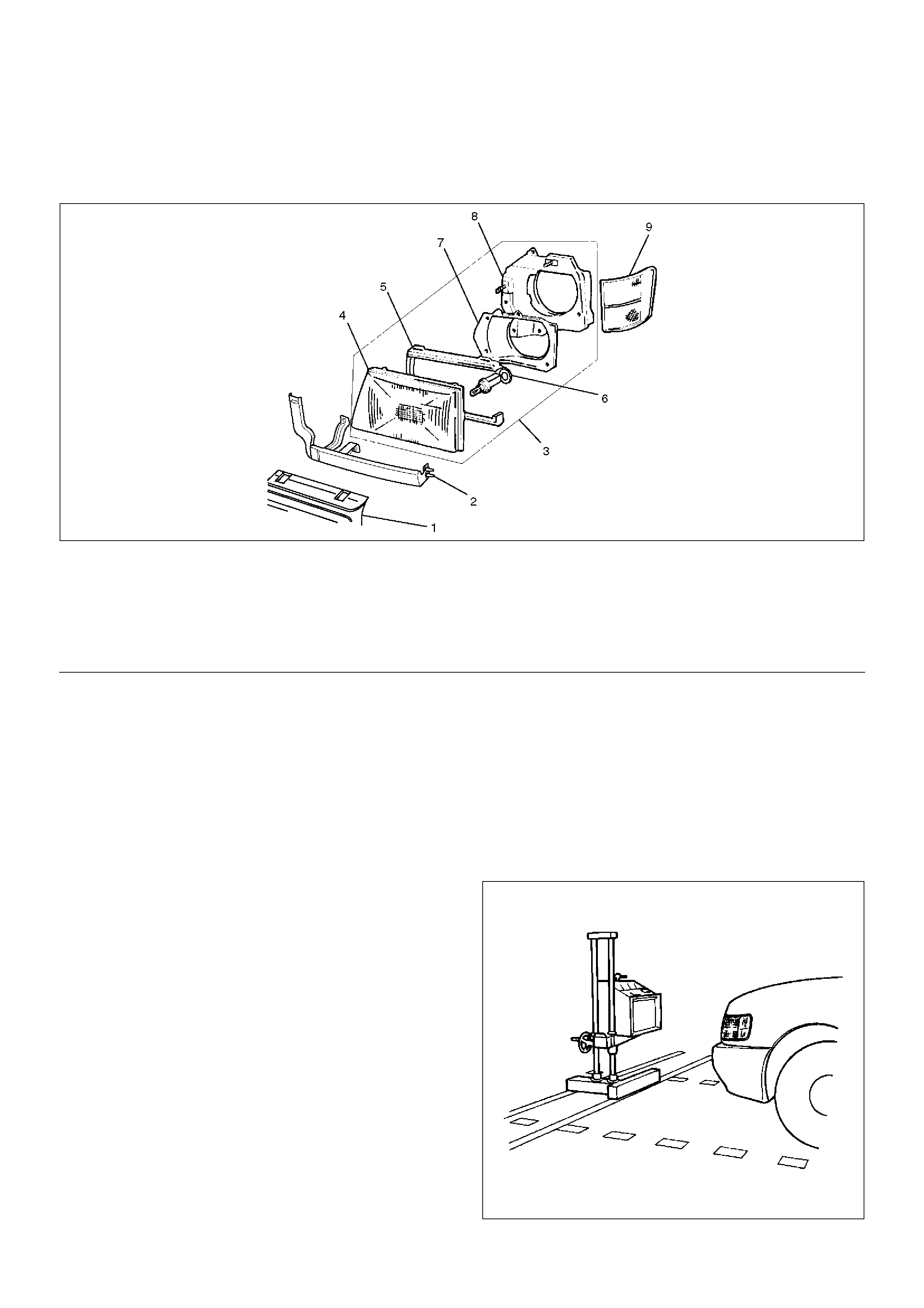
Headlamp
Headlamp and Associated Parts
801RW003
EndOFCallout
Removal
1. Disconnect the battery ground cable.
2.Remove the screw and pull out the two projecting
portions on the fender to remove the front
combination lamp.
3.Remove five clips and two screws to remove the
radiator grille.
4.Remove two screws to remove the front end lower
panel(2).
5.Remove two bolts and two nuts to remove the
headlamp assembly (with bracket).
6.Remove the headlamp bulb.
7.Remove two screws, two nuts and the spring for the
headlamp aim adjustment to remove the bracket.
8.Remove four screws to remove the rear cover.
9.Remove the headlamp rim.
10.Remove the headlamp.
Installation
To install, follow the removal steps in the reverse order.
CAUTION: After installing the headlamp, be sure to
adjust the headlamp aim.
Headlamp Adjustment
Preparation
Place the unloaded vehicle on a level surface and
check to see if the inflation pressure of the tires is
correct, the lenses are clean, and the battery is
sufficiently charged. Adjust the aim with the headlamp
tester, if necessary.
When adjusting, follow the procedure of the tester
manufacturer's.
801RS009
Legend
(1) Radiator Grille
(2) Front End Lower Panel
(3) Headlamp Assembly
(4) Headlamp
(5) Headlamp Rim
(6) Headlamp Bulb
(7) Rear Cover
(8) Bracket
(9) Front Combination lamp
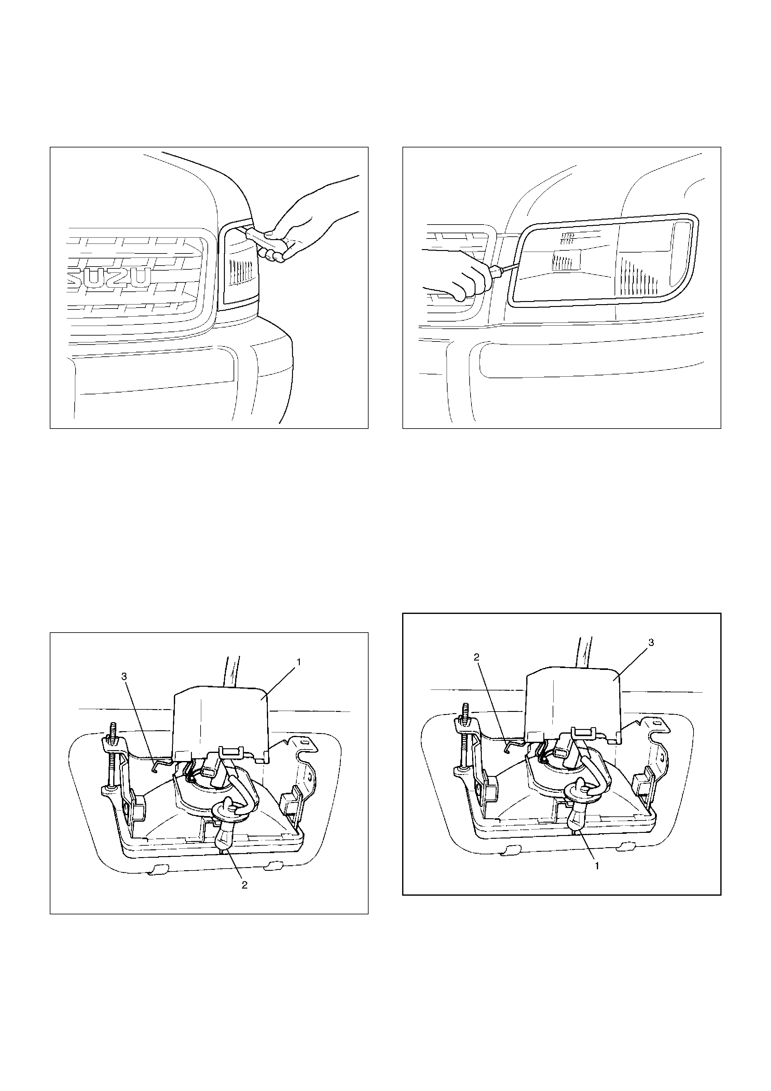
Vertical adjustment
Use a screwdriver for vertical adjustment.
801RW004
Horizontal adjustment
Use a screwdriver for horizontal adjustment.
801RW005
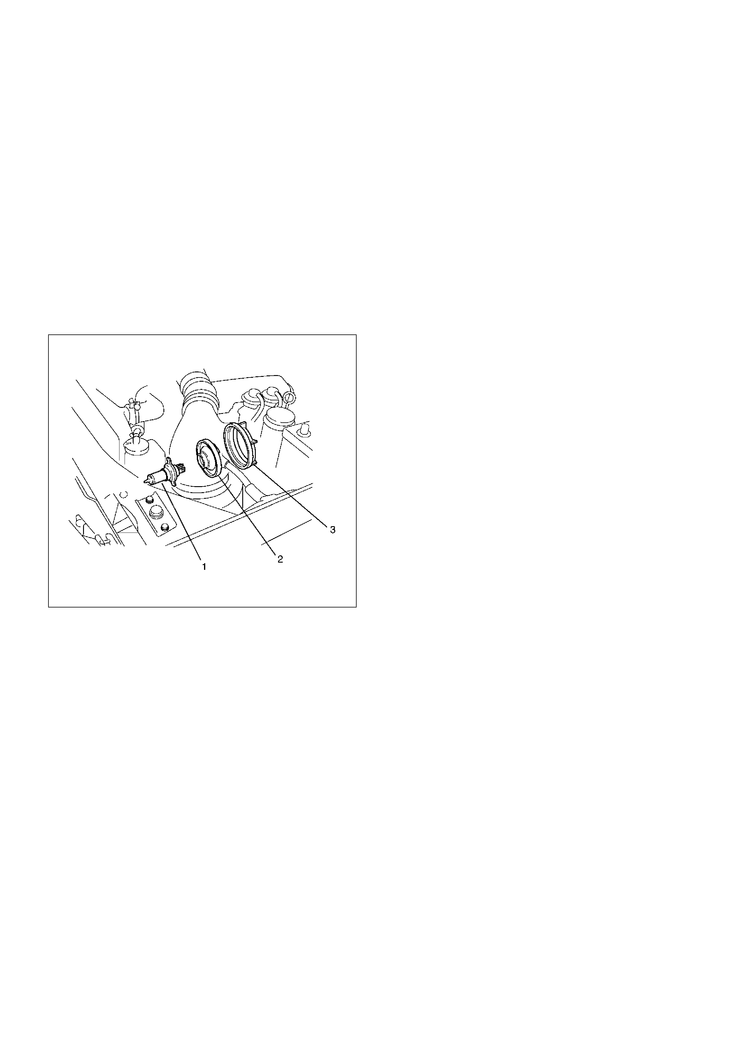
Fog lamp Bulb
Removal
1. Disconnect the battery ground cable.
2. Open the rear cover(1) of the case.
3. Remove the dust cover.
4. Disconnect the bulb connector.
5. Remove the clip(3).
6. Remove the fog lamp bulb(2).
801RW012
Installation
1. Install the fog lamp bulb(1).
2. Install the clip(2).
3. Connect the bulb connector.
4. Install the dust cover.
5. Close the rear cover(3) of the case.
801RW017
6. Connect the battery ground cable.
Fog lamp Assembly
Removal
1.Disconnect the battery ground cable.
2.Remove two nuts from the bracket.
3.Disconnect the connector.
4.Remove the fog lamp assembly (1).
825RW104
Installation
To install, follow the removal steps in the reverse order.
CAUTION: After installing the fog lamp, be sure to
adjust the fog lamp aim.
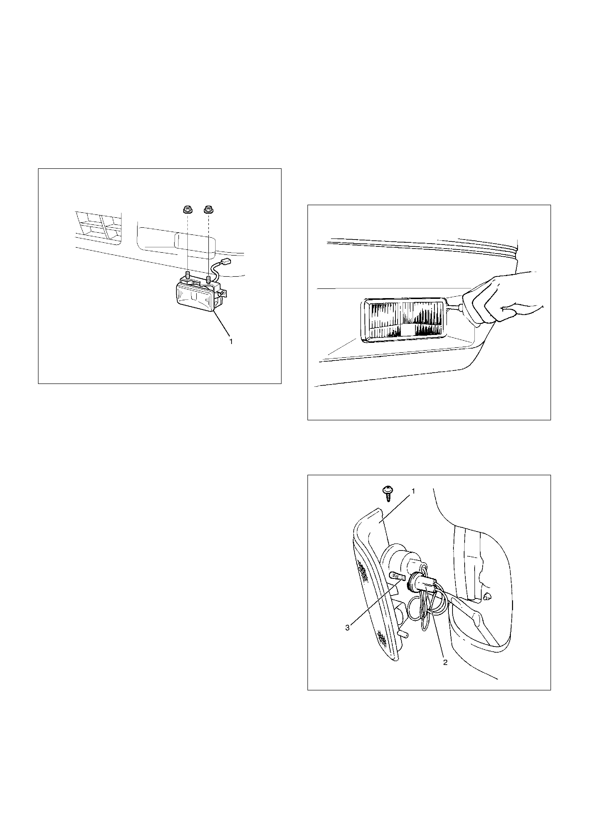
Fog lamp Adjustment
Turn the adjusting screw with a screwdriver to adjust the
aim of the fog lamp vertically.
801RW007
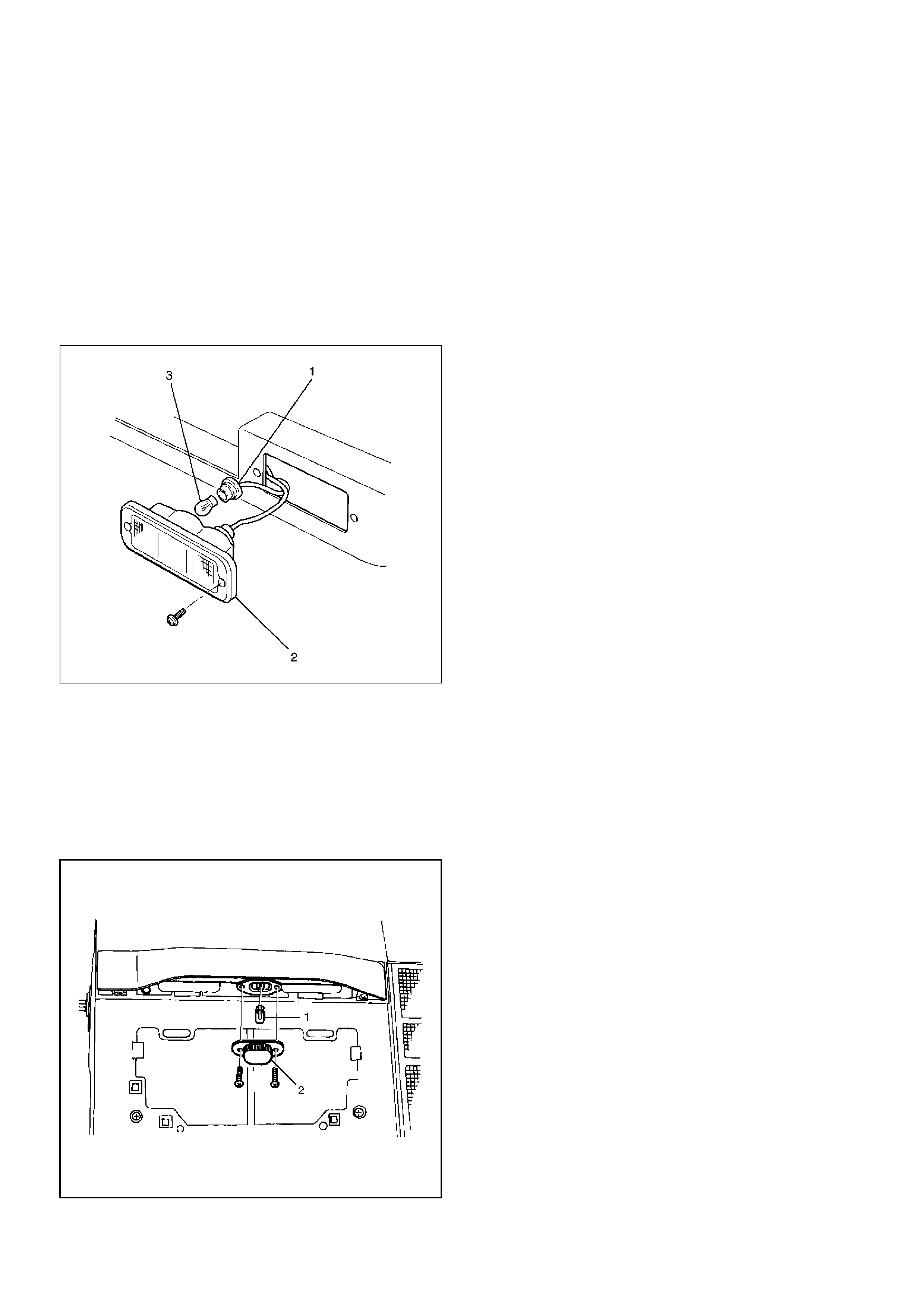
Park lamp Bulb
Removal
1. Disconnect the battery ground cable.
2. Remove the screw at the upper portion of the lamp
bracket and then remove the bracket from the
fender.
3. Remove the front combination lamp assembly (1).
4. Remove the front side marker lamp socket (2) by
turning it counterclockwise.
5. Pull out the bulb (3) from the socket.
801RW015
Installation
To install, follow the removal steps in the reverse order.
Tail lamp Bulb (Body)
Removal
1. Disconnect the battery ground cable.
2. Remove three screws and release locks at two
locations to remove the rear combination lamp
assembly(2).
3. Remove the socket(3) by turning it
counterclockwise.
4. Turn the bulb(1) counterclockwise while pushing it
to remove it from the socket.
803RS005
Installation
To install, follow the removal steps in the reverse order.
Tail lamp Bulb (Bumper)
Removal
1. Disconnect the battery ground cable.
2. Remove two screws to remove the rear combination
lamp assembly(2).
3. Remove the socket(1) by turning it
counterclockwise.
4. Remove the bulb(3) by turning it counterclockwise
while pushing.
803RW004
Installation
To install, follow the removal steps in the reverse order.
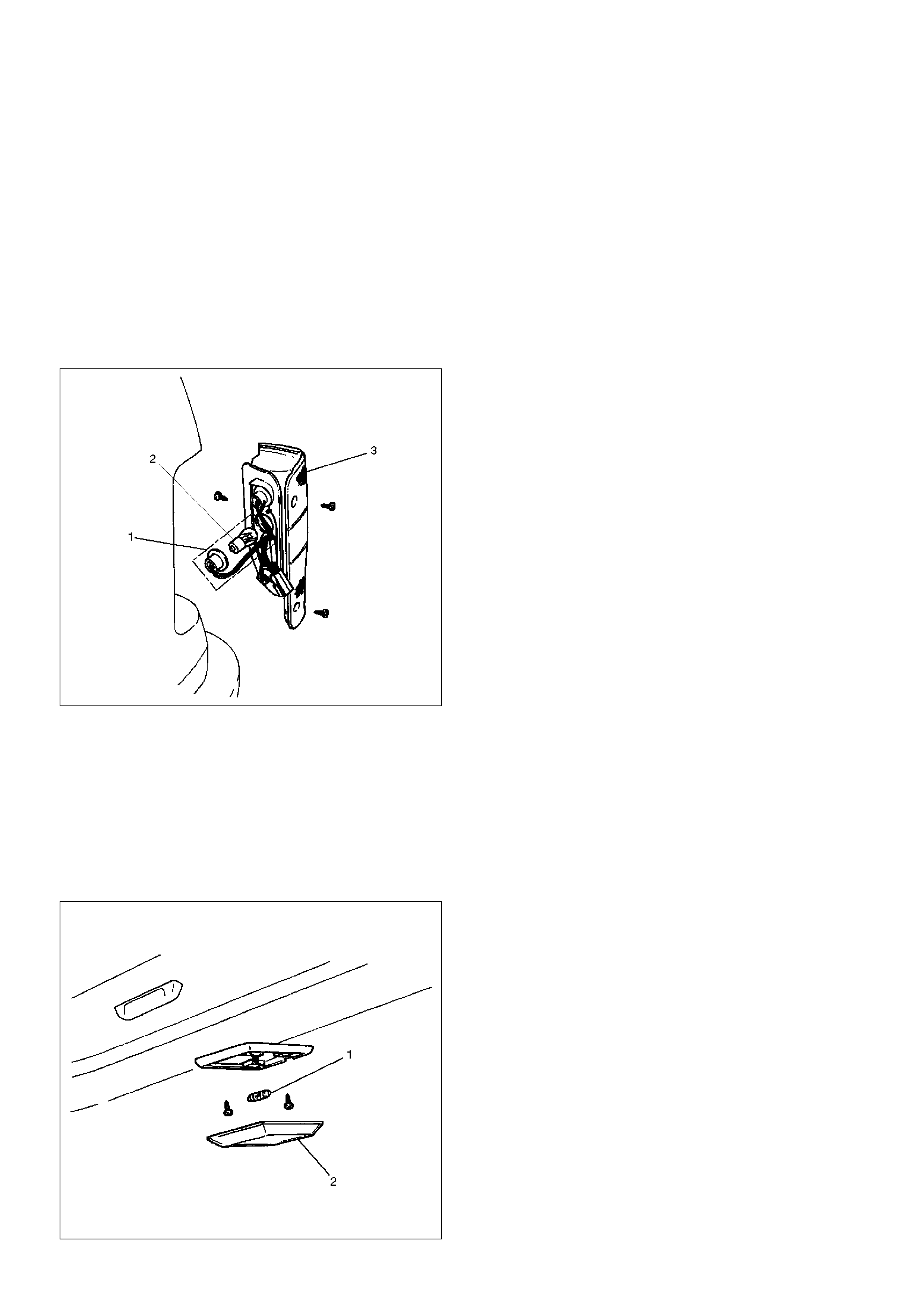
License Plate lamp Bulb (Body)
Removal
1. Disconnect the battery ground cable.
2. Remove two screws to remove the lens(2).
3. Pull out the bulb(1) from the socket.
803RS006
Installation
To install, follow the removal steps in the reverse order.
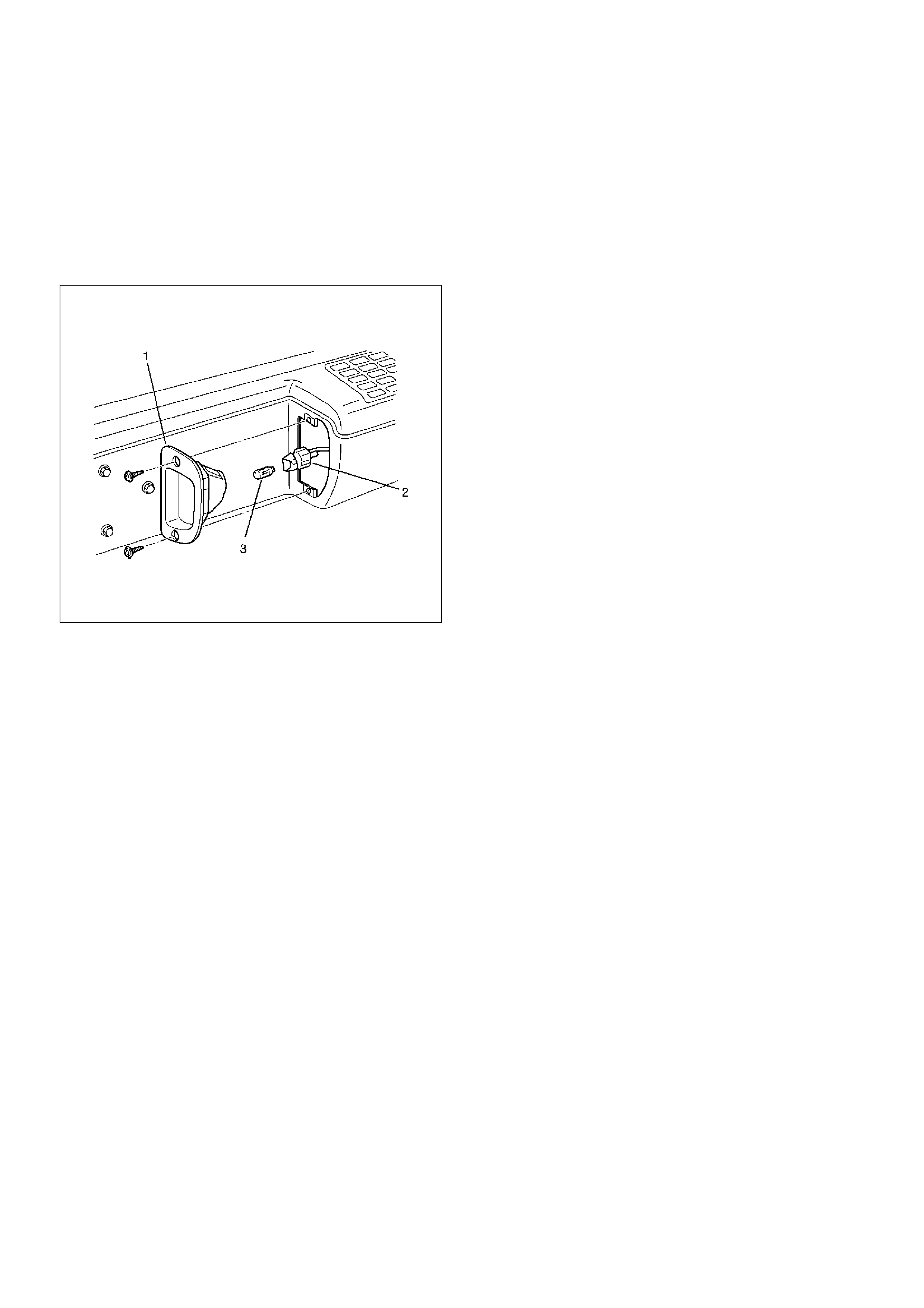
License Plate lamp Bulb (Bumper)
Removal
1.Disconnect the battery ground cable.
2.Remove two screws to remove the license plate
lamp(1).
3.Pull out the bulb(3) from the socket(2).
803RW003
Installation
To install, follow the removal steps in the reverse order.
Stoplamp Bulb
Removal and Installation
Refer to the Taillamp Bulb in this section.
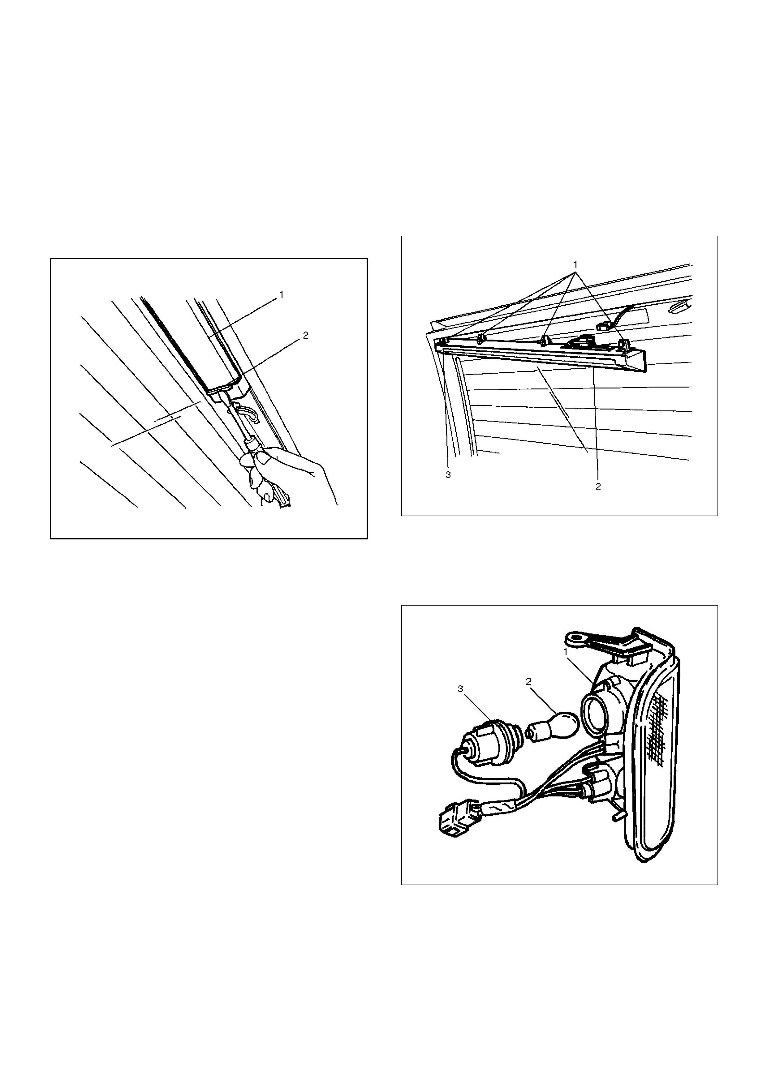
High Mount Stoplamp
Removal
1. Disconnect the battery ground cable.
2. Remove the clips(2).
3. Pull out the high mount stoplamp(1).
4. Remove the connector.
5. Remove the high mount stoplamp.
803RS003
Installation
1. Insert the clips(1)(3) into the high mount
stoplamp(2).
2. Reconnect the connector.
3. Install the high mount stoplamp.
803RS004
Front Turn Signal lamp Bulb
Removal
1. Disconnect the battery ground cable.
2. Remove the screw at the upper portion of the lamp
bracket, and remove the bracket from the fender.
3. Remove the front combination lamp(1).
4. Remove the turn signal lamp socket(3) by turning it
counterclockwise.
5. Remove the bulb(2) by turning it counterclockwise
while pushing it at the same time.
801RS002
Installation
To install, follow the removal steps in the reverse order.
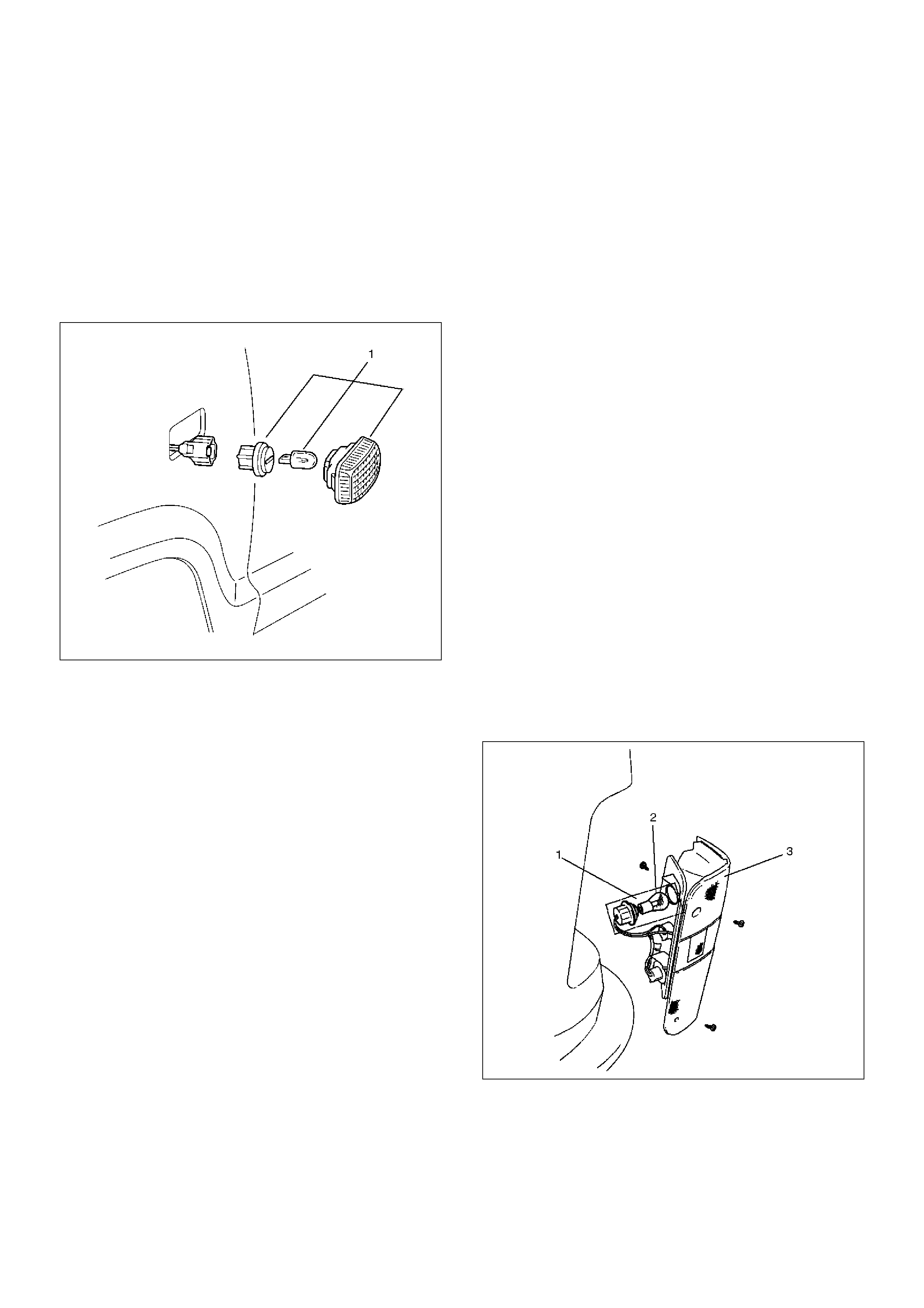
Side Turn Signal lamp Bulb
Removal
1. Disconnect the battery ground cable.
2. Pull the lamp/bulb(1) toward you while pushing the
lamp housing in the rear direction of the vehicle to
release its lock.
3. Remove the bulb by turning it counterclockwise
while pushing it at the same time.
801RW013
Installation
To install, follow the removal steps in the reverse order.
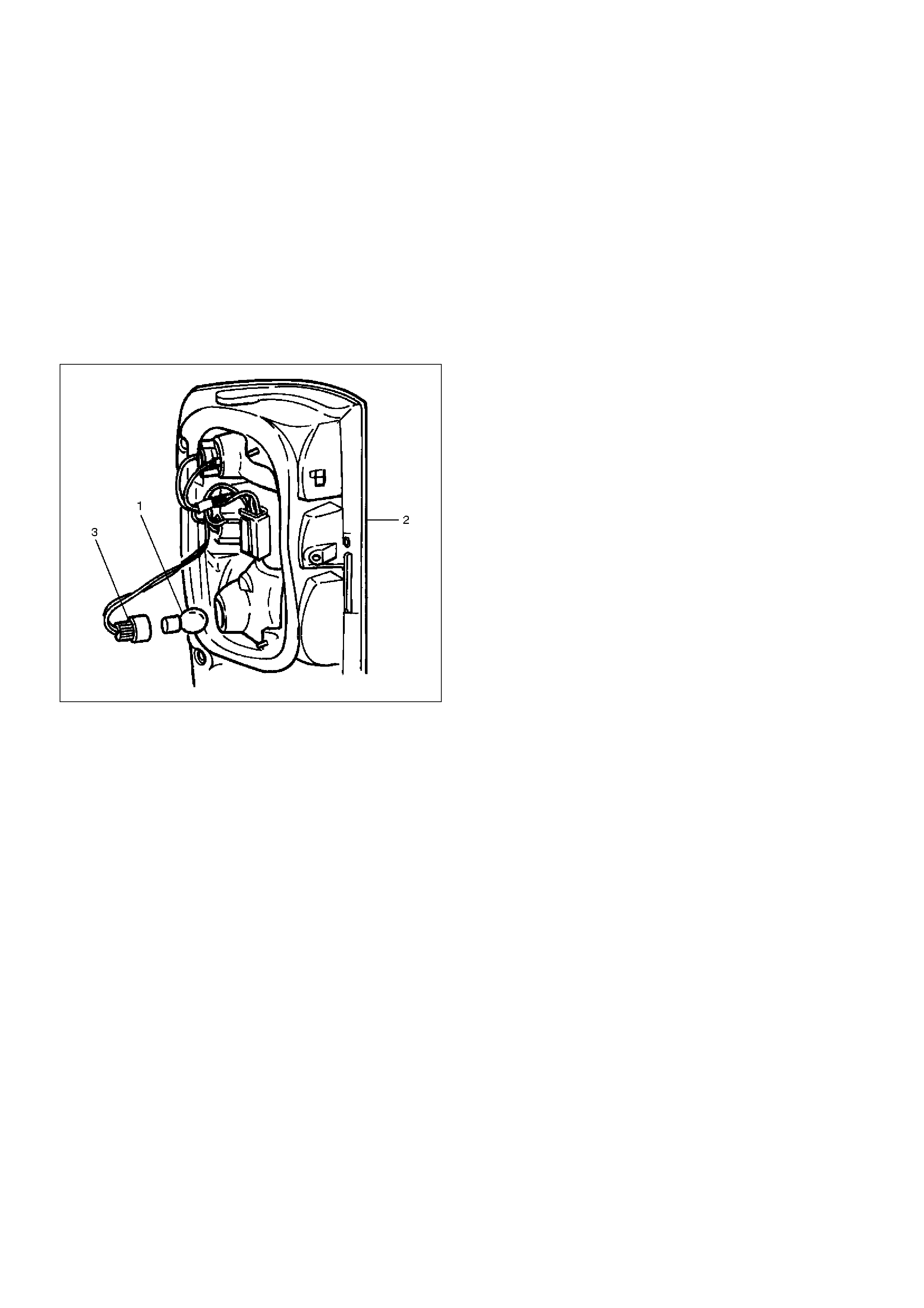
Rear Turn Signal lamp Bulb
Removal
1. Disconnect the battery ground cable.
2. Remove the three screws and release the lock at
two positions.
3. Remove the rear combination lamp(3).
4. Remove the turn signal lamp socket/bulb(1) by
turning it counterclockwise.
5. Remove the bulb(2) by turning it counterclockwise
while pushing it at the same time.
803RS002
Installation
To install, follow the removal steps in the reverse order.
Backup lamp Bulb
Removal
1. Disconnect the battery ground cable.
2. Remove three screws and release the lock at two
positions.
3. Remove the rear combination lamp(3).
4. Remove the backup lamp socket/bulb(1) by turning
it counterclockwise.
5. Remove the bulb(2) by turning it counterclockwise
while pushing it at the same time.
803RS001
Installation
To install, follow the removal steps in the reverse order.
Dome lamp Bulb
Removal
1. Disconnect the battery ground cable.
2. Remove the lens(2) by releasing the locks at three
locations.
3. Remove the bulb(1).
Installation
To install, follow the removal steps in the reverse order.

Luggage Room lamp Bulb
Removal
1. Disconnect the battery ground cable.
2. Remove the lens(2) by releasing the locks at four
locations.
3. Remove the bulb(1).
803RS007
Installation
To install, follow the removal steps in the reverse order.
Courtesy lamp Bulb
Removal
1. Disconnect the battery ground cable.
2. Remove two screws to remove the lens(1).
3. Pull out the bulb(2) from the socket.
805RS006
Installation
To install, follow the removal steps in the reverse order.
Map lamp Switch/Bulb
Removal
1. Disconnect the battery ground cable.
2. Pull the map lamp body downward to release the
lock.
3. Disconnect the connectors of the map lamp and the
sun roof switch.
4. Remove the map lamp switch.
5. Turn the socket counterclockwise to remove it.
6. Pull out the bulb from the socket.
805RS008
Installation
To install, follow the removal steps in the reverse order.
Cigar Lighter Illumination Bulb
Removal
1. Disconnect the battery ground cable.
2. Remove eight screws to remove the instrument
cluster panel(2).
3. Turn the socket counterclockwise to remove it then
pull out the bulb(1).
826RS013
Installation
To install, follow the removal steps in the reverse order.
Ashtray Illumination Bulb
Removal
1. Disconnect the battery ground cable.
2. Removal eight screws to remove the instrument
cluster panel(1).
3. Remove the ashtray(5).
4. Remove four screws to remove the audio box(4).
5. Remove two screws to remove the ashtray guide(2).
6. Turn the socket counterclockwise to remove it then
pull out the bulb(3).
742RS001
Installation
To install, follow the removal steps in the reverse order.
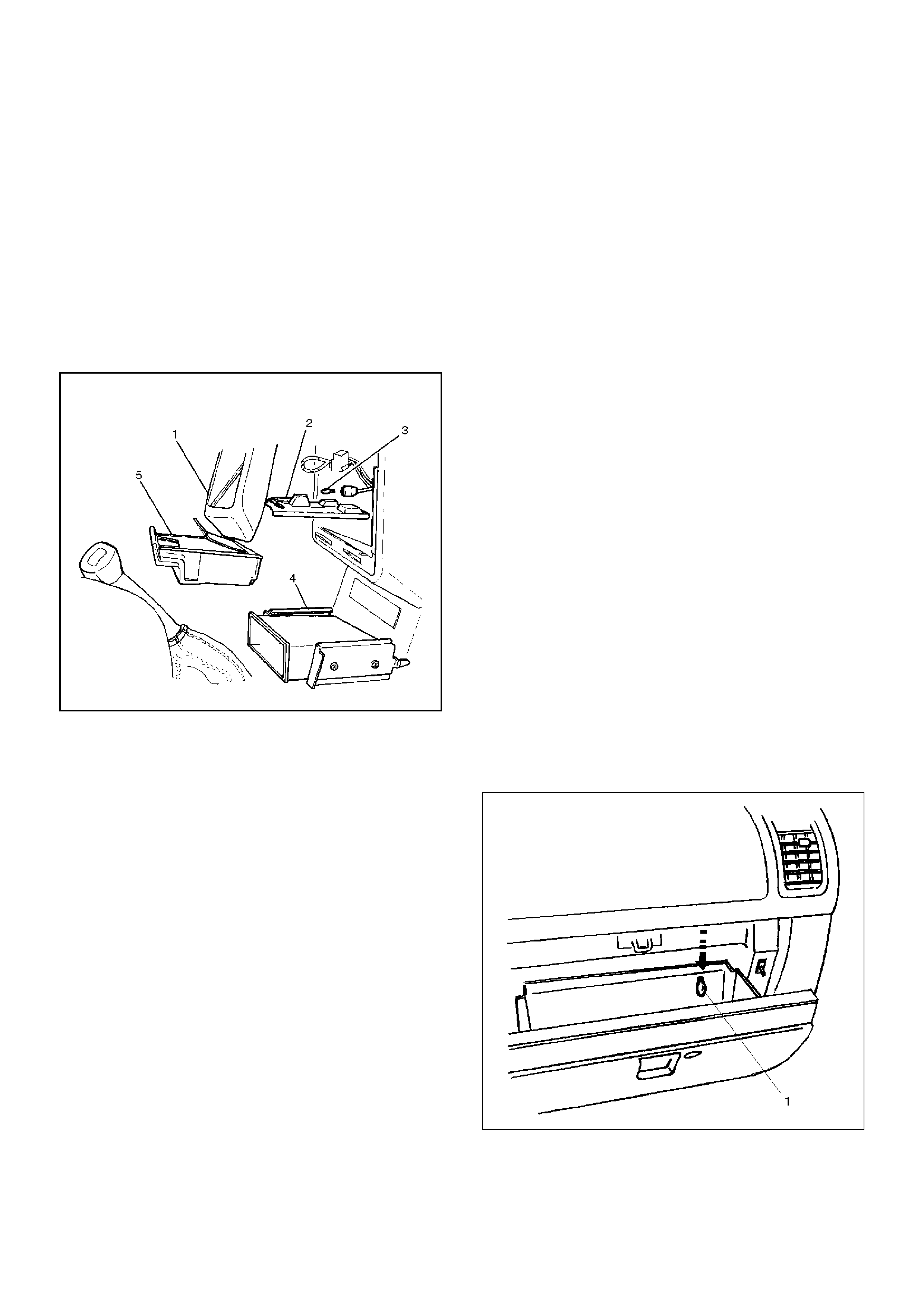
Glove Box Illumination Bulb
Removal
1. Disconnect the battery ground cable.
2. Open the glove box lid, and then pull out the bulb(1).
805RS004
Installation
To install, follow the removal steps in the reverse order.
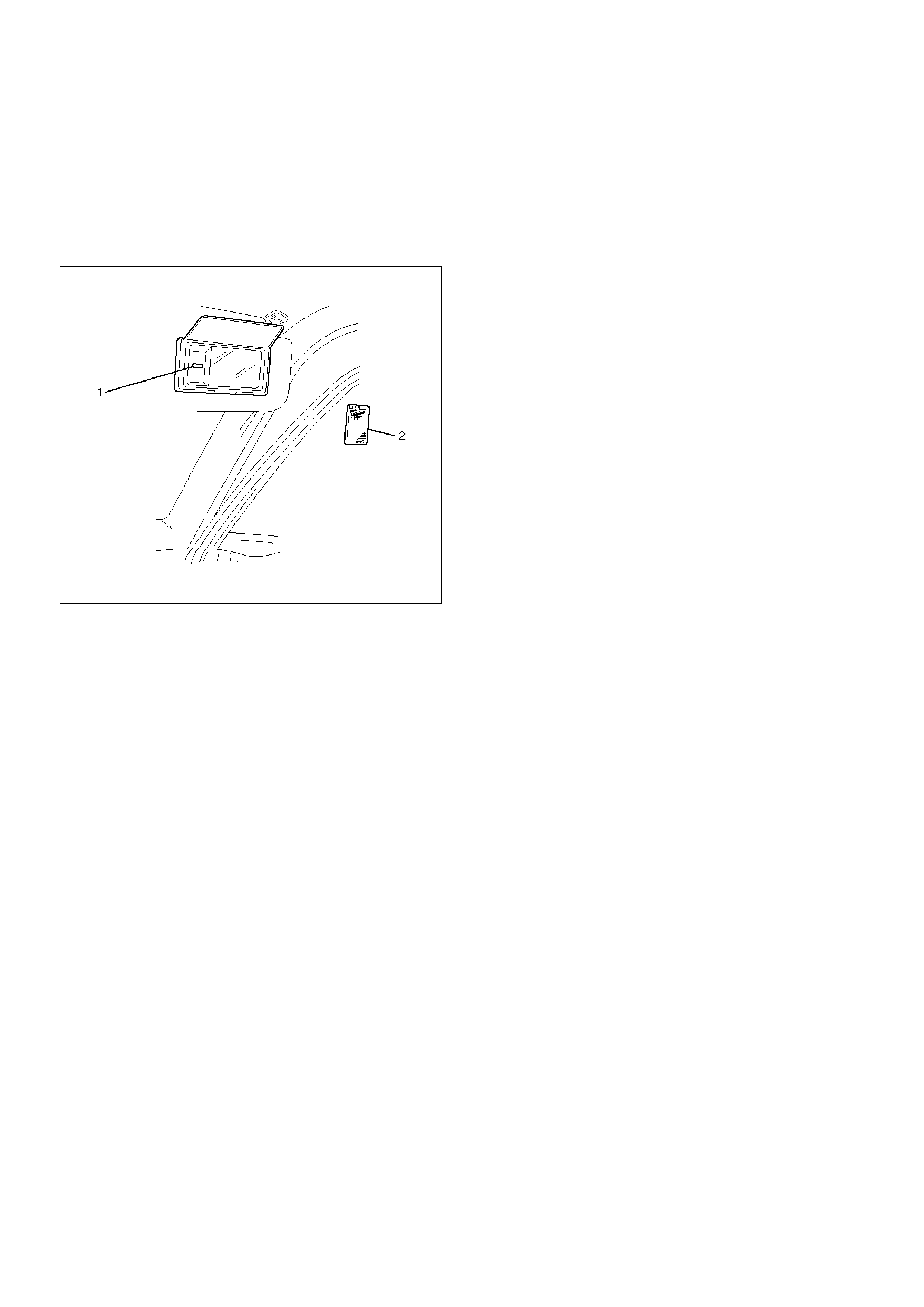
Vanity Mirror Illumination Bulb
Removal
1. Disconnect the battery ground cable.
2. Remove the lens(2).
3. Remove the bulb(1).
743RW007
Installation
To install, follow the removal steps in the reverse order.
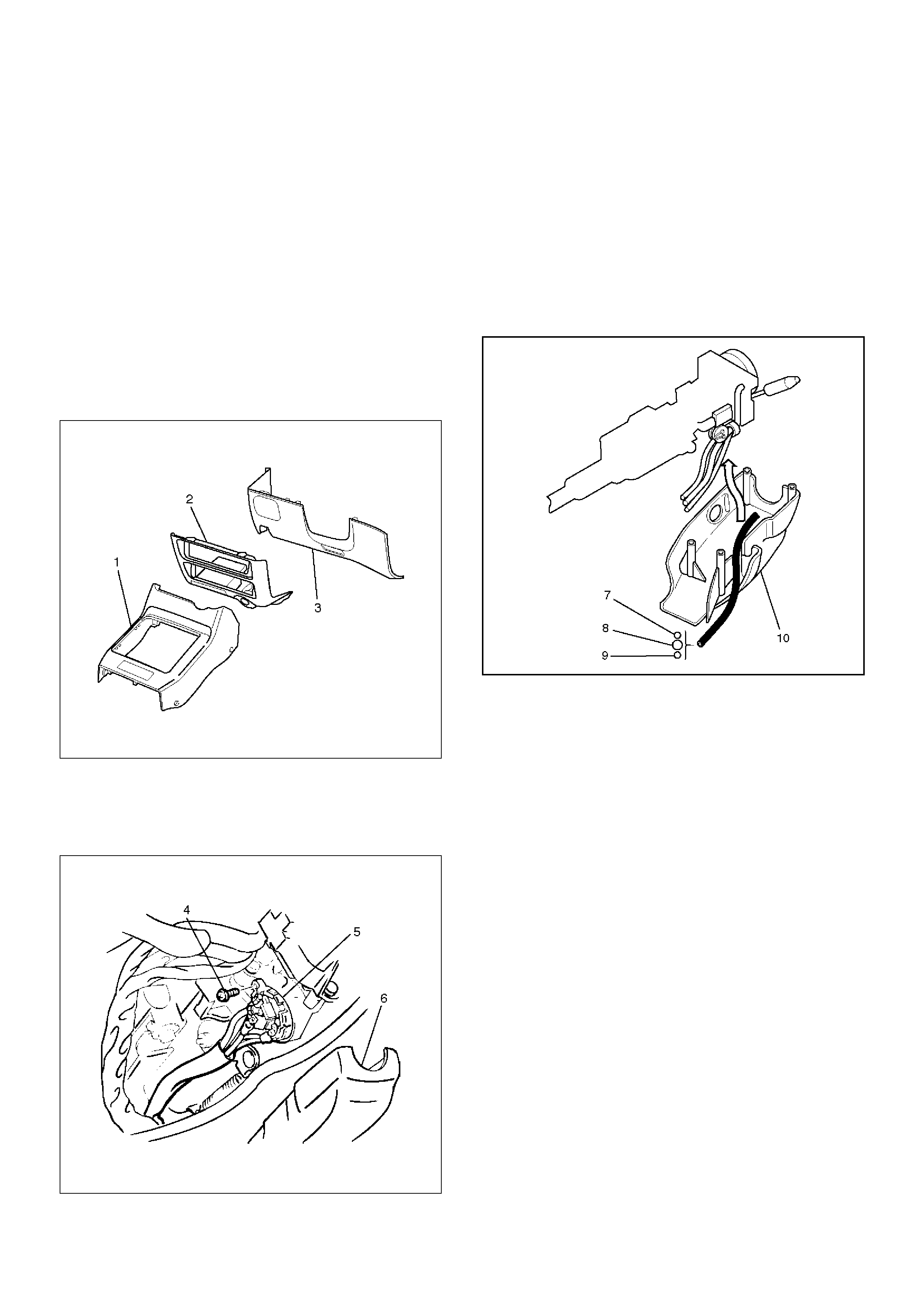
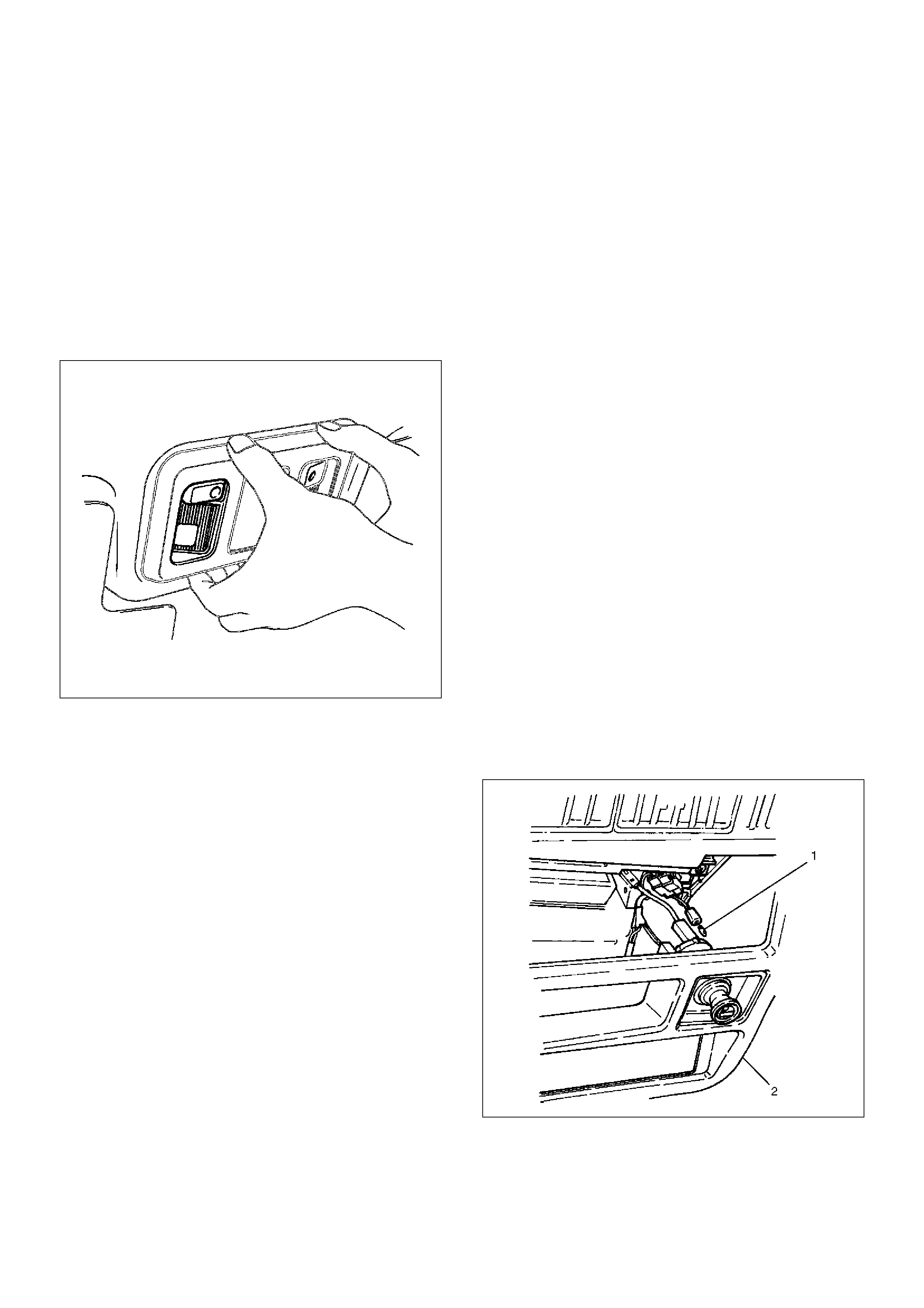
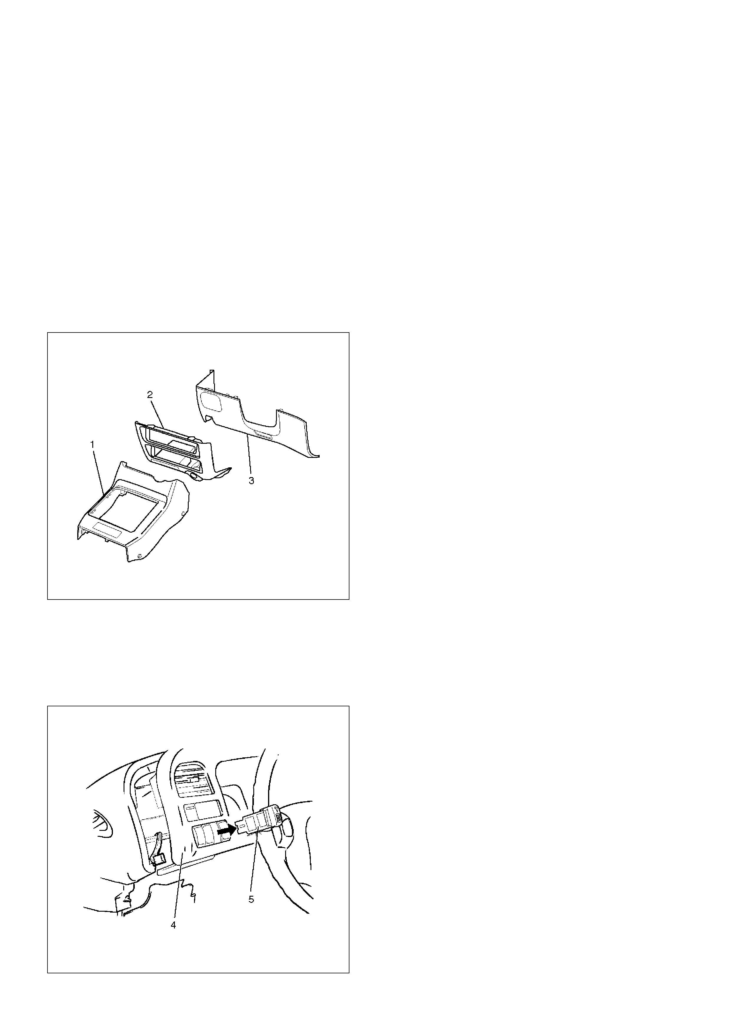
Starter Switch
Removal
1.Disconnect the battery ground cable.
2.Remove the front console assembly(1).
Refer to Instrument Panel Assembly in Body
Structure section.
3. Remove the lower cluster assembly(2).
Refer to the Instrument Panel Assembly in Body
Structure section.
4. Remove the instrument panel driver lower cover
assembly(3).
Refer to the Instrument Panel Assembly in Body
Structure section.
821RW024
5. Remove seven screws to remove the steering
cowl(6).
6. Disconnect the connector, remove the screw(4) and
then remove the starter switch(5).
431RW005
Installation
To install, follow the removal steps in the reverse order
noting the following point.
1. When installing the steering cowl(10), be sure to
pass the harnesses through the route as shown in
the figure so that the starter switch harness(7), the
combination switch harness(8) and the inflator
module harness(9) will not get caught.
431RW008
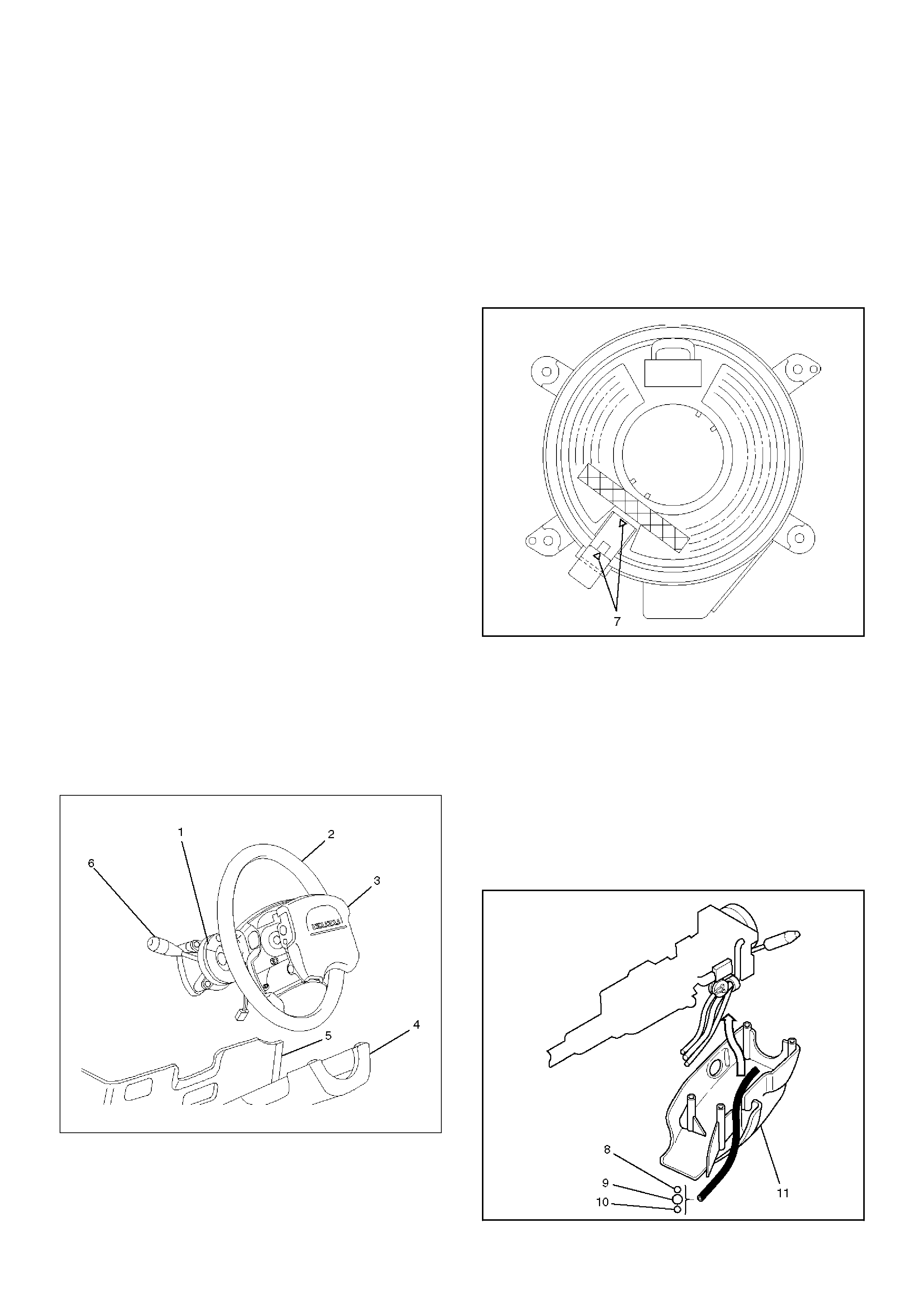
Lighting Switch (Combination Switch)
Removal
1.Disconnect the battery ground cable.
2.Remove the instrument panel driver lower cover(5).
Refer to the Instrument Panel Assembly in Body
Structure section.
3.Remove seven screws to remove the steering
cowl(4).
4.Disconnect the SDM (air bag controller) connector
located at lower of the instrument panel driver lower
cover.
5.Remove four fixing screws and disconnect the
driver inflator module connector to remove the
driver inflator module(3).
CAUTION: When carrying a live inflator module,
make sure the bag opening is pointed away from
you. In case of an accidental deployment, the bag
will then deploy with minimal chance of injury.
Never carry the inflator module by the wires or
connector on the underside of the module.
When placing a live inflator module on a bench or
other surface, always face the bag and trim cover
up, away from the surface. This is necessary so that
a free space is provided to allow the air bag to
expand in the unlikely event of accidental
deployment.
6.Remove the steering wheel(2).
Refer to the Steering Wheel in Steering section.
7.Disconnect the SRS coil assembly connector,
remove four fixing screws to remove the SRS coil
assembly(1).
8.Disconnect the lamping switch connector, remove
four fixing screws to remove the lamping switch(6).
825RS039
Installation
To install, follow the removal steps in the reverse order,
noting the following points.
1. Check to see if the vehicle is in the straight driving
condition and turn the rotary section of the SRS coil
assembly provided to the upper surface of the
lamping switch (combination switch)
counterclockwise fully until it stops.
Then from where it stops, turn it back about 3
rotations to set the alignment marks(7) together
before installing the steering wheel.
825RW099
2. Tighten the steering shaft nut to the specified
torque.
Torque: 34N·m(3.5 kg·m/25lbft)
3. When connect the double lock type of inflator
module connector, insert the connector completely
and lock at outside.
Imperfect locking may cause malfunction of SRS
system circuit.
4. When installing the steering cowl(11), be sure to
pass the harnesses through the route as shown in
the figure so that the starter switch harness(8), the
combination switch harness(9) and inflator module
harness(10) will not get caught.
431RW014
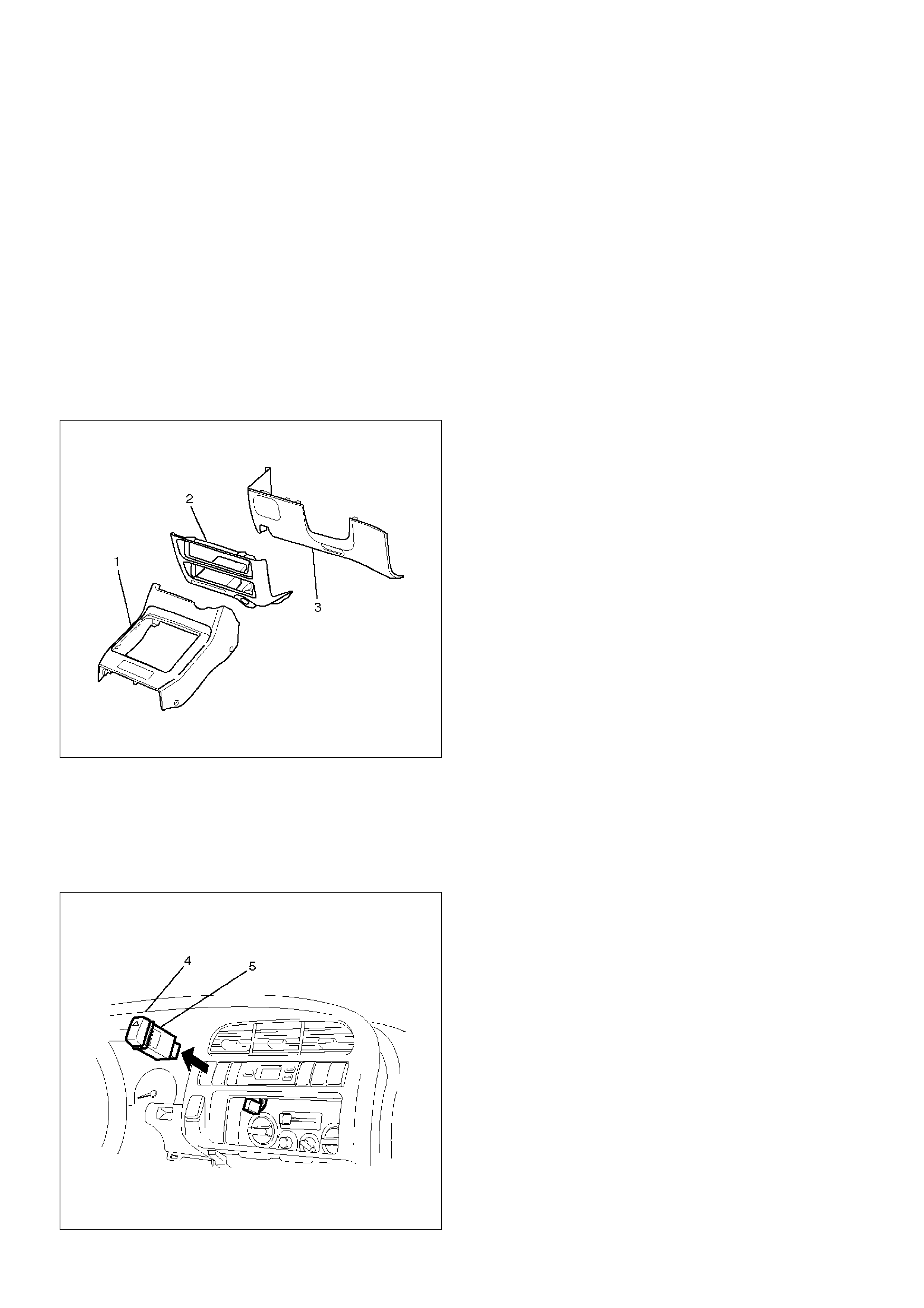
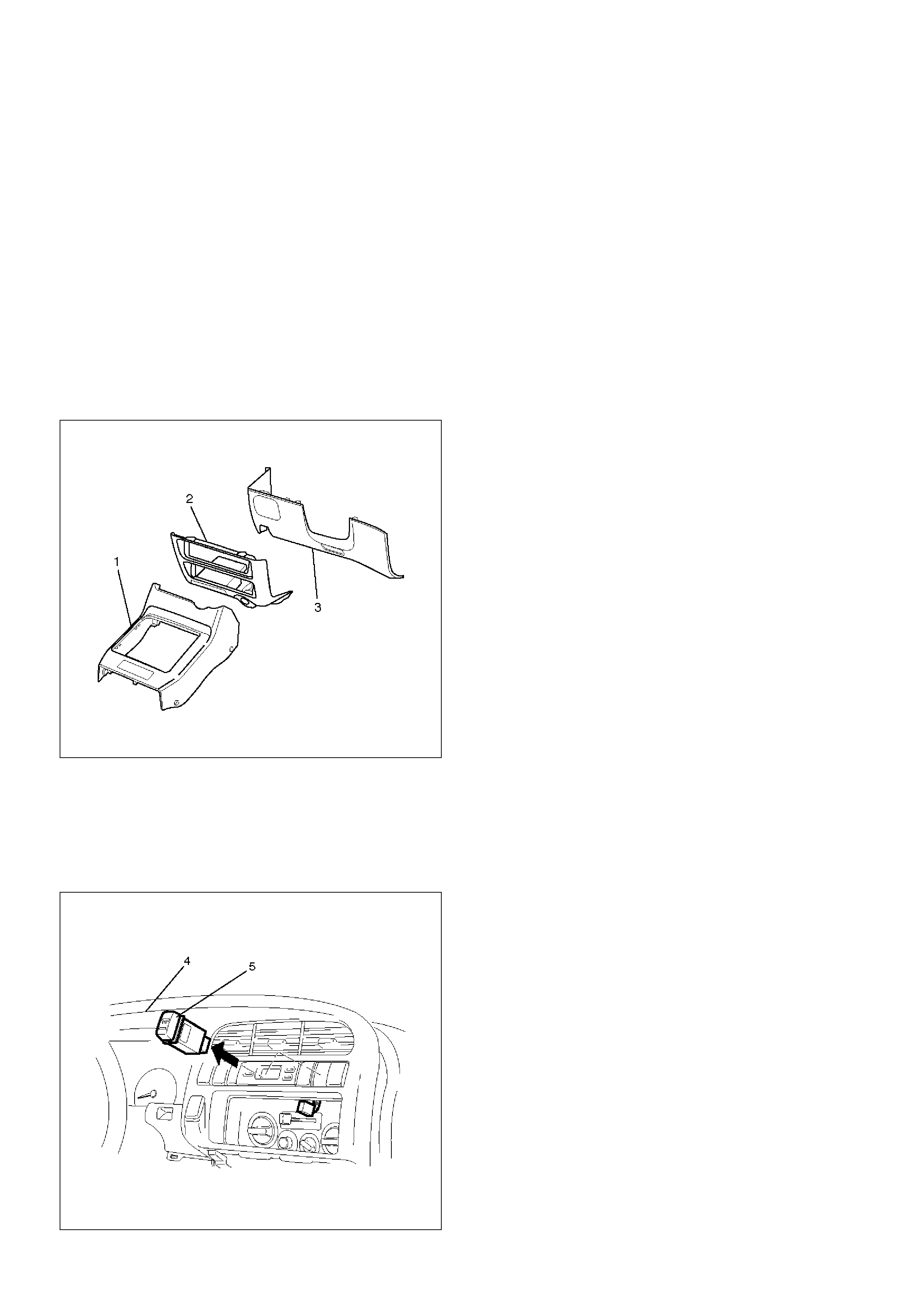
Fog lamp Switch
Removal
1.Disconnect the battery ground cable.
2.Remove the front console assembly(1).
Refer to the Instrument Panel Assembly in Body
Structure section.
3.Remove the lower cluster assembly(2).
Refer to the Instrument Panel Assembly in Body
Structure section.
4.Remove the instrument panel driver lower cover
assembly(3).
Refer to the Instrument Panel Assembly in Body
Structure section.
821RW024
5.Remove the instrument panel cluster assembly(4).
Refer to the Instrument Panel Assembly in Body
Structure section.
6. Disconnect the connector and push the lock from
the back side of the instrument panel cluster
assembly to remove the fog lamp switch(5).
825RW027
Installation
To install, follow the removal steps in the reverse order,
noting the following point:
1. Push in the switch with your fingers until the switch
is locked securely.
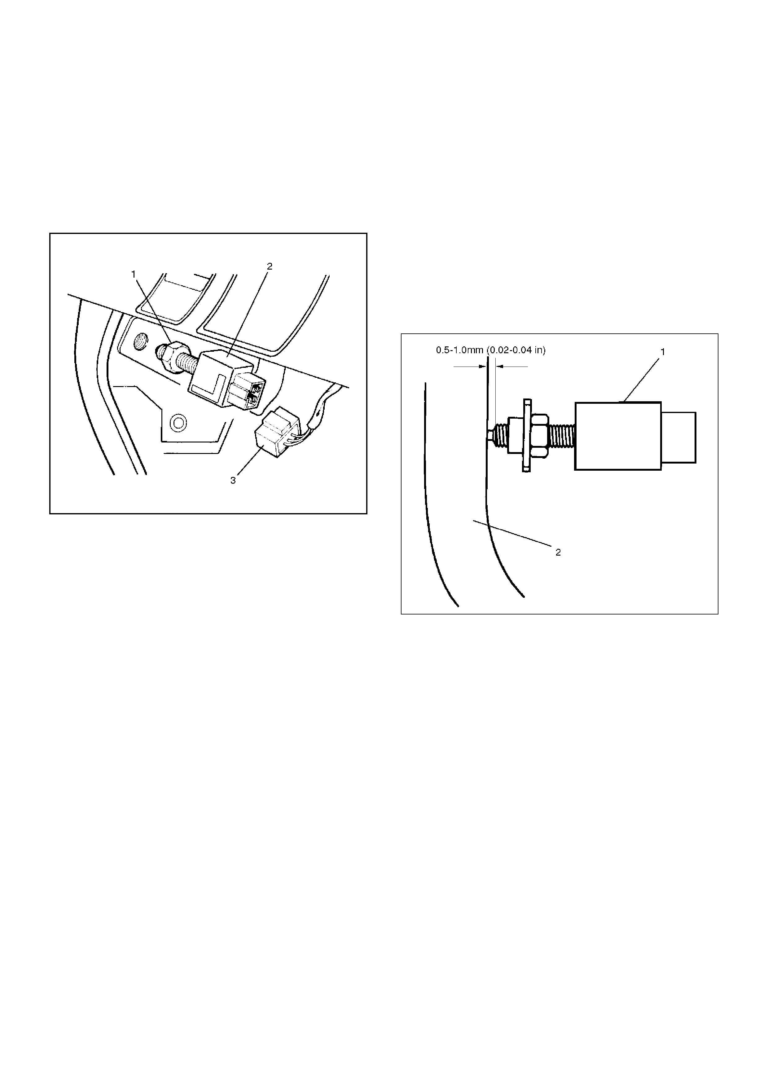
Stoplamp Switch (W/O Cruise Control)
Removal
1. Disconnect the battery ground cable.
2. Disconnect the connector(3), loosen the lock nut(1)
and then remove the stoplamp switch(2) by turning
it.
310RS007
Installation
To install, follow the removal steps in the reverse order,
noting the following points.
1. Check to see if the brake pedal has been returned
by the return spring to the specified position.
2. Turn the stoplamp switch(1) clockwise until the tip of
the threaded portion of the switch contacts the pedal
arm(2).
3. Turn the switch counterclockwise until the space
between the tip of the threaded portion and the
pedal arm is 0.5 to 1.0mm (0.02–0.04in.).
310RS006
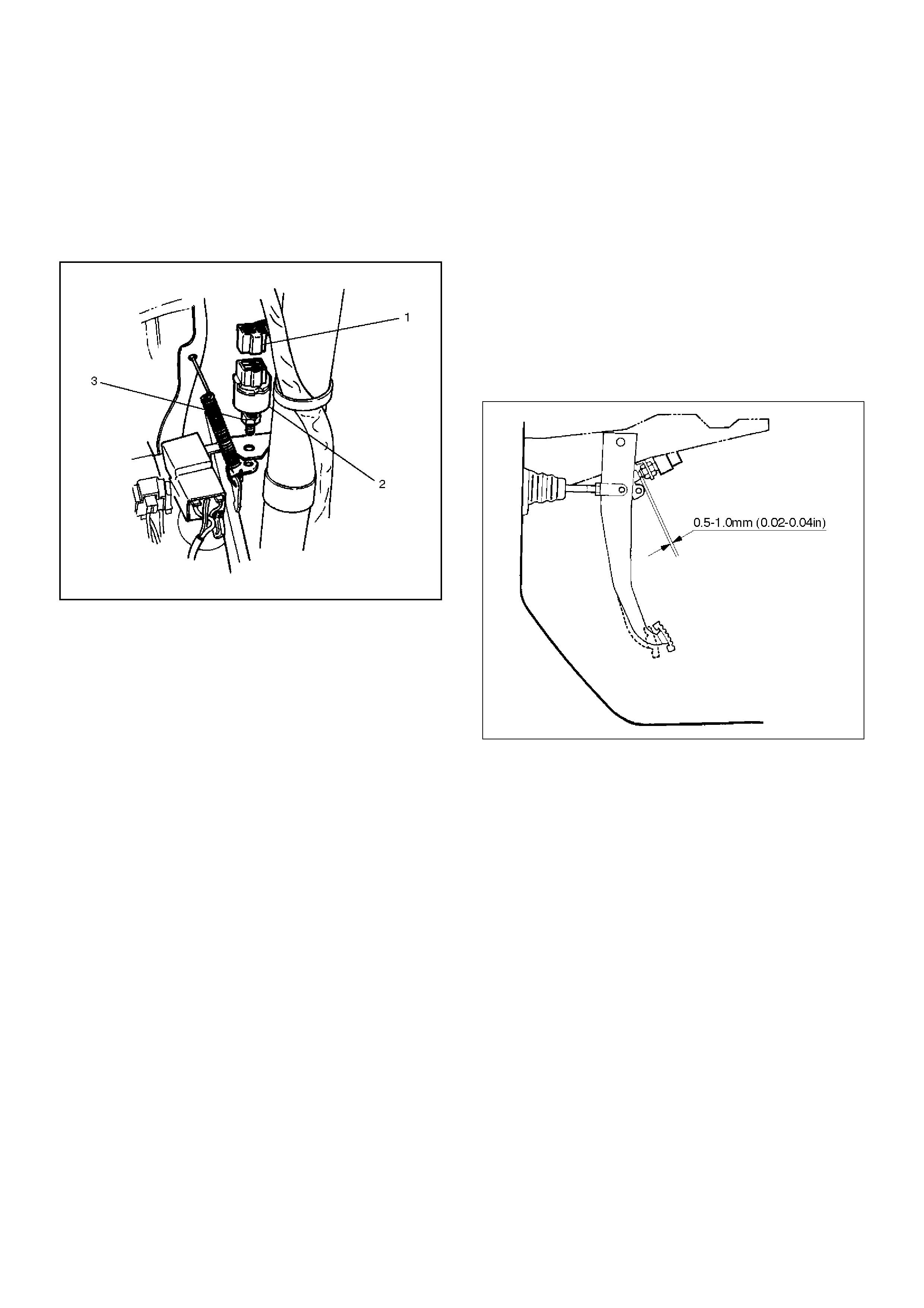
Brake Switch (W/Cruise Control)
Removal
1.Disconnect the battery ground cable.
2.Disconnect the connector(1), loosen the lock nut(3)
and then remove the brake switch(2) by turning it.
310RW010
Installation
To install, follow the removal steps in the reverse order,
noting the following points.
1.Check to see if the brake pedal has been returned
by the return spring to the specified position.
2.Turn the switch clockwise until the tip of the
threaded portion of the brake switch contacts the
pedal arm.
3.Turn the switch counterclockwise until the space
between the tip of the threaded portion and the
pedal arm is 0.5 to 1.0mm (0.02–0.04in.).
310RS003
Turn Signal Switch (Combination Switch)
Removal and Installation
Refer to the removal and installation steps of the
Lighting Switch (Combination Switch) in this section.
Hazard Warning Switch
Removal
1.Disconnect the battery ground cable.
2.Remove the front console assembly(1).
Refer to the Instrument Panel Assembly in Body
Structure section.
3.Remove the lower cluster assembly(2).
Refer to the Instrument Panel Assembly in Body
Structure section.
4.Remove the instrument panel driver lower cover
assembly(3).
Refer to the Instrument Panel Assembly in Body
Structure section.
821RW024
5.Remove the instrument panel cluster assembly(4).
Refer to the Instrument Panel Assembly in Body
Structure section.
6. Disconnect the connector and push the lock from
the back side of the instrument panel cluster
assembly to remove the hazard warning switch(5).
825RW024
Installation
To install, follow the removal steps in the reverse order,
noting the following point.
1. Push in the switch with your fingers until it locks
securely.

Tailgate Switch
Removal
1. Disconnect the battery ground cable.
2. Remove the screw and disconnect the connector(1)
to remove the tailgate switch(2).
683RS014
Installation
To install, follow the removal steps in the reverse order.
Door Switch
Removal
1. Disconnect the battery ground cable.
2. Remove the screw and disconnect the connector to
remove the door switch(1).
825RS043
Installation
To install, follow the removal steps in the reverse order.
Rear Demister Switch
Removal
1.Disconnect the battery ground cable.
2.Remove the front console assembly(1).
Refer to the Instrument Panel Assembly in Body
Structure section.
3.Remove the lower cluster assembly(2).
Refer to the Instrument Panel Assembly in Body
Structure section.
4.Remove the instrument panel driver lower cover
assembly(3).
Refer to the Instrument Panel Assembly in Body
Structure section.
821RW024
5.Remove the instrument panel cluster assembly(4).
Refer to the Instrument Panel Assembly in Body
Structure section.
6. Disconnect the connector and push the lock from
the back side of the instrument panel cluster
assembly to remove the rear demister switch(5).
825RW023
Installation
To install, follow the removal steps in the reverse order,
noting the following point.
1. Push in the switch with your fingers until it locks
securely.
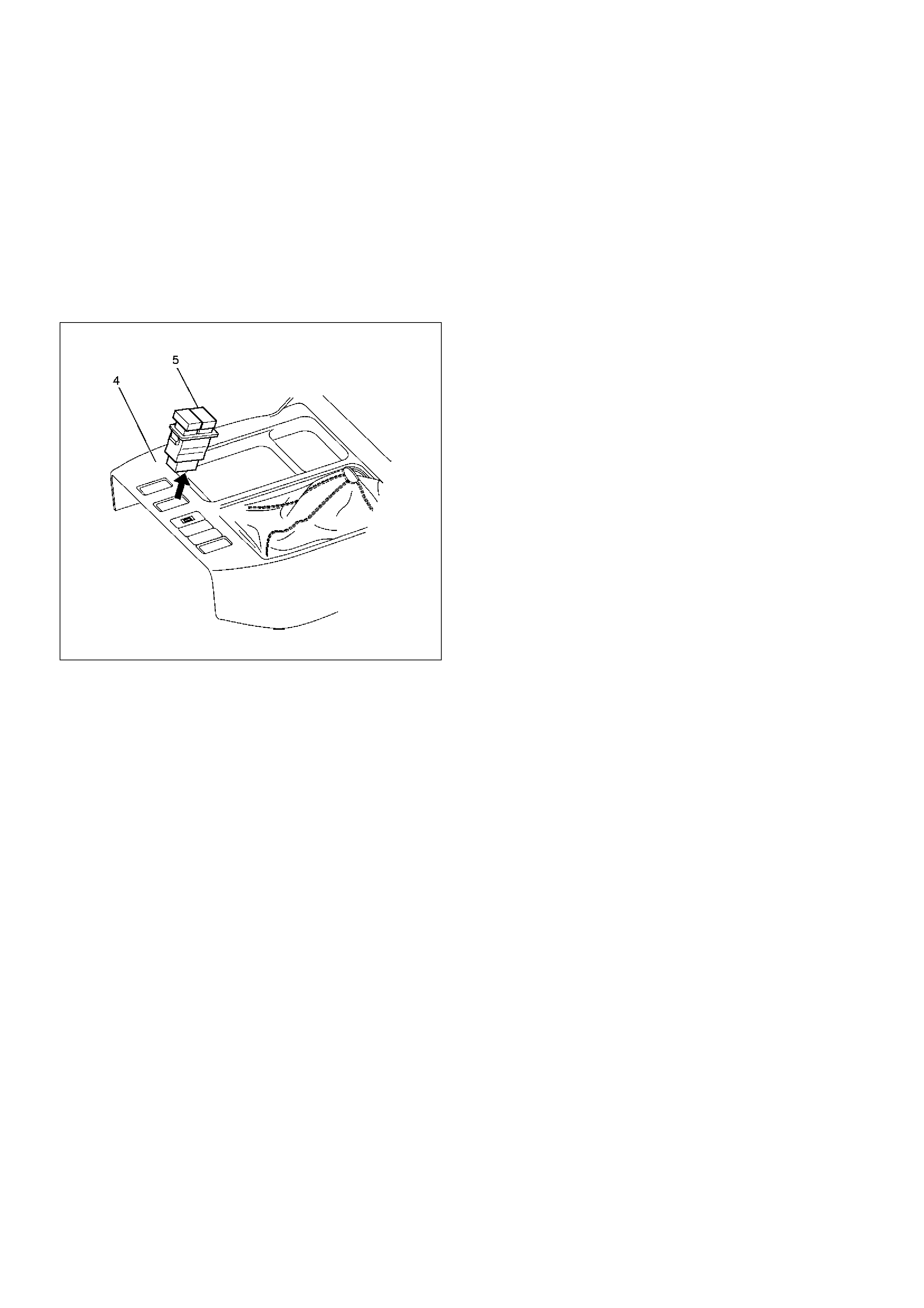
Seat Heater Switch
Removal
1.Disconnect the battery ground cable.
2.Remove four fixing screws and disconnect the
switch connectors to remove the front console
assembly(4).
3.Push the lock from the back side of the front console
assembly to remove the seat heater switch(5).
825RW025
Installation
To install, follow the removal steps in the reverse order,
noting the following point.
1.Push the switch with your fingers until it locks
securely.
Key Remind Switch (Starter Switch)
Removal and Installation
Refer to the removal and installation on steps of the
Starter Switch in this section.
Illumination Controller
Removal
1.Disconnect the battery ground cable.
2.Remove the front console assembly(1).
Refer to the Instrument Panel Assembly in Body
Structure section.
3.Remove the lower cluster assembly(2).
Refer to the Instrument Panel Assembly in Body
Structure section.
4.Remove the instrument panel driver lower cover
assembly(3).
Refer to the Instrument Panel Assembly in Body
Structure section.
821RW024
5.Remove the instrument panel cluster assembly(4).
Refer to the Instrument Panel Assembly in Body
Structure section.
6. Disconnect the connector and push the lock from
the back side of the instrument panel cluster
assembly to remove the illumination controller(5).
825RW026
Installation
To install, follow the removal steps in the reverse order,
noting the following point.
1. Push in the switch with your fingers until the switch
is locked securely.
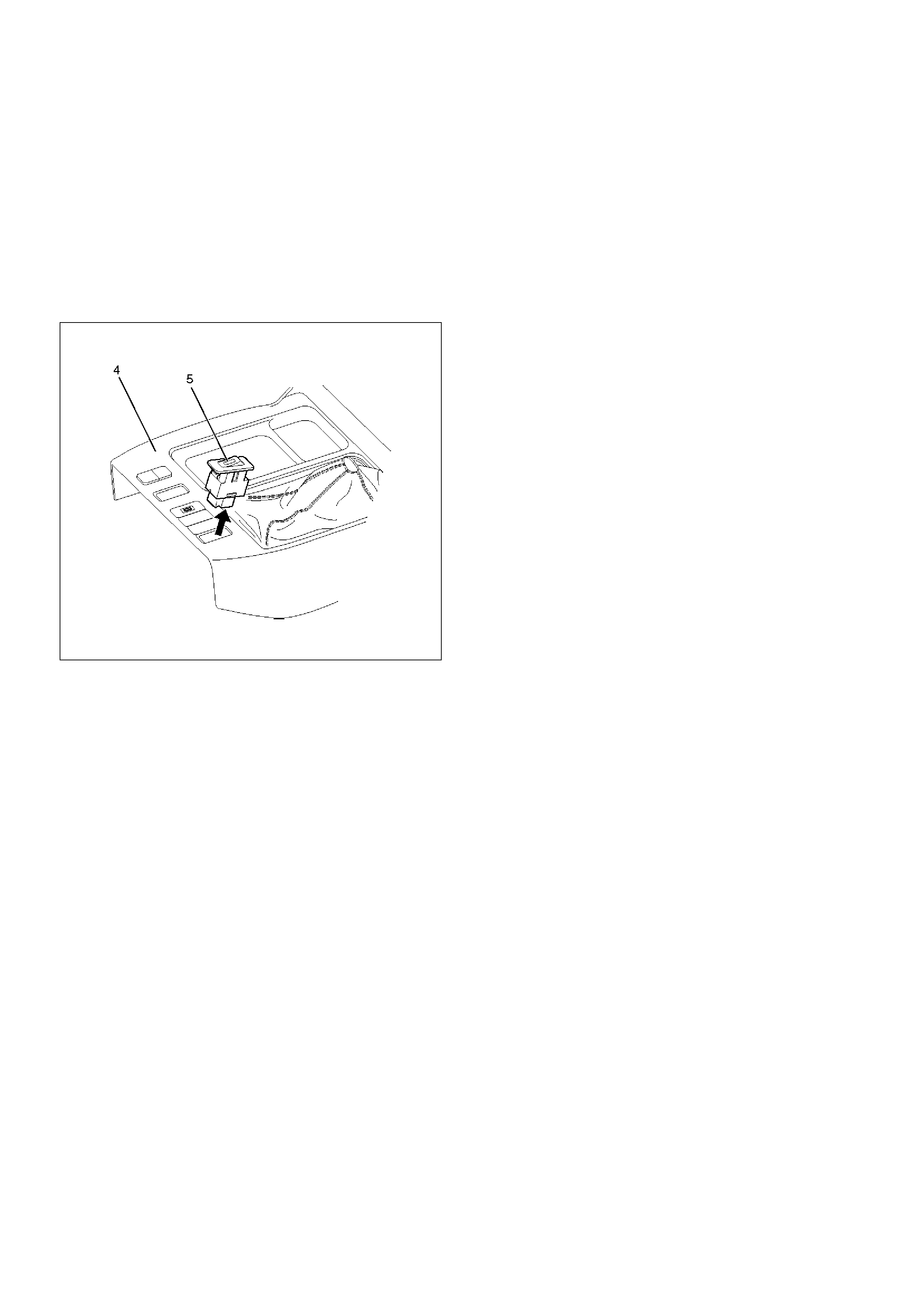
Power/Winter Switch
Removal
1. Disconnect the battery ground cable.
2. Remove four fixing screws and disconnect the
switch connectors to remove the front console
assembly(4).
3. Push the lock from the back side of the front console
assembly to remove the power/winter switch(5).
825RW204
Installation
To install, follow the removal steps in the reverse order,
noting the following point.
1. Push the switch with your fingers until it locks
securely.
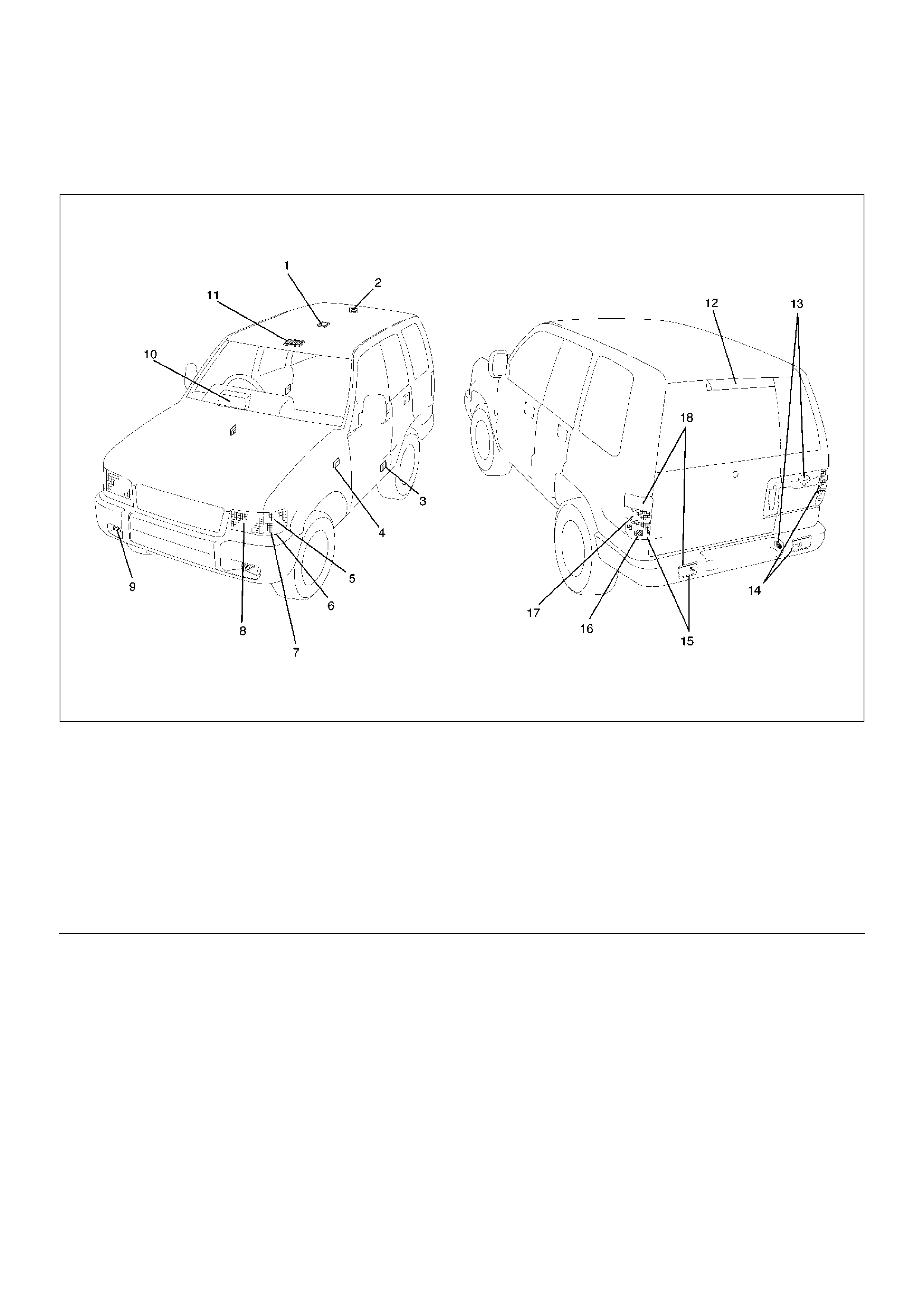
Main Data and Specifications
lamp and Bulb Specifications
D08RW539
EndOFCallout
Legend
(1) Dome lamp
(2) Luggage Room lamp
(3) Courtesy lamp
(4) Side Turn Signal lamp
(5) Front Turn Signal lamp
(6) Park lamp
(7) Front Combination lamp
(8) Headlamp
(9) Fog lamp
(10) Meter
(11) Map lamp
(12) High Mount Step lamp
(13) License Plate lamp
(14) Rear combination lamp
(15) Taillamp/Stoplamp
(16) Rear Fog lamp
(17) Backup lamp
(18) Rear Turn Signal lamp.

lamp Name Rated Power Number of
Bulbs Lens Color Remarks
Headlamp 60w/55w 2White Halogen
Front
combination
lamp
Turn signal lamp 21w 2White
Park lamp 5w 2Amber
FRT fog lamp 55w 2White Halogen
Rear
combination
lamp
Bumper Taillamp/Stoplamp 5w/21w 2Red
Turn signal lamp 21w 2Amber
Body Taillamp/Stoplamp 5w/21w 2Red
Turn signal lamp 21w 2Amber
Backup lamp 21w 2White
Side turn signal lamp 5w 2Amber
License plate lamp Bumper 5w 2White
Body 5W 1White
High mount stoplamp — — Red LED
Map lamp 5w 2White
Dome lamp 10w 1White
Luggage room lamp 8w 1White
Courtesy lamp 3.8w 2White
Indicator/
Warning
lamp
A/C SW 60mA 1
RR demister SW 0.84w 1
Mirror demister SW 0.84w 1
FRT fog lamp SW 0.7w 1
Cruise (Set) 1.4w 1Meter
Cruise (Main) 1.4w 1Meter
Check trans 3w 1Meter
Anti-theft 3w 1Warning box
Turn signal 1.4w 2Meter
Golw 1.4w 1Meter
Water sedimenter 1.4w 1Meter
High beam 1.4w 1Meter
ABS 1.4w 1Meter
Check engine 1.4w 1Meter
Low fuel 1.4w 1Meter
4WD 1.4w 1Meter
Oil Pressure 1.4w 1Meter
Brake system 1.4w 1Meter
Charge 1.4w 1Meter
Seat belt 2w 1Meter
A/T shift position 0.91w 7Meter
A/T oil temp 3w 1Meter
Power drive 1.4w 1Meter
Winter drive 1.4w 1Meter
Air bag 2w 1Meter

Torque Specifications
Illumination
lamp
Engine warming SW 0.84w 1
FRT fog lamp SW 0.84w 1
Glove box 1.2w 1
Ashtray 1.4w 1
Illumination controller 0.7w 1
Heater bezel 150mA 2
Hazard warning lamp SW 0.84w 1
Meter 3.4w 4Meter ASM
Cigar lighter 1.4w 1
Rear wiper & washer SW 0.84w 1
Rear demister SW 0.84w 1
Mirror control SW 45mA 1
Mirror demister SW 0.7w 1
Mirror folding SW 0.7w 1
A/T select lever 1.2w 1
Power & Winter SW 50mA 2
Cruise control main SW 0.84w 1
Headlamp wiper SW 0.84w 1
lamp Name Rated Power Number of
Bulbs Lens Color Remarks
Application N·m kg·m LbFt LbIn
Steering Shaft Nut 34 3.5 25 —