
SECTION 12H-1 - ANTI-THEFT & KEYLESS ENTRY SYSTEM
GENERAL DESCRIPTION
LOCKING/UNLOCKING THE VEHICLE
ARMING & DISARMING THE ANTI-THEFT SYSTEM
ANTI-THE F T SYSTE M
Components
Control Unit
Anti-theft Horn
Anti-theft Indicator Lamp
DOOR / TAILGATE / HOOD SWITCHES
Front Door Key Switch
Front Door Lock Key Switch
Engine Hood Switch
KEYLESS ENTRY
Components
Control Unit
Remote Keypads
Keypad Types
KEYPAD TESTING
ID CODE ADDITIONAL REGISTRATION
ID CODE NEW REGISTRATION
ID CODE CHECK
PROGRAMMING THE ANSWER-BACK FUNCTION -
(MY1998-1999 ONLY)
Initial Diagnosis
Anti-Theft/Keyless Entry Harness Connector
Anti-theft System Check Procedure
Anti-Theft System Diagnostic Procedure Chart
Anti-Theft System Diagnostic Procedure Chart
SYSTEM WIRING CIRCUITS

GENERAL DESCRIPTION
Two separate theft deterrent systems were introduced on the 1998 UBS Jackaroo and Monterey:
• Illegal Entry Warning - provided by the Anti-theft/Keyless Entry System fitted to Jackaroo SE and Monterey.
• Drive-away theft deterrent - provided on all models by the Engine Immobiliser System.
The basic ce ntr al locki ng syste m is com mon for all UB S SE and Montere y mo del s. The cen tral locki ng sy st em can be
operated by the mechanical keys, the door lock buttons or the remote keypads.
The Illegal Entry Warning System (more commonly referred to as the Anti-theft/Keyless Entry System), can only be
armed or disarmed with either the mechanical keys or the remote keypads.
MY1998 v ehicles were i nitially supp lied with one rem ote keypad per veh icle (During 1999, an additi onal keypad was
supplied on owner request for all MY1998 SE and Monterey models). All subsequent vehicles from MY1999 have
been supplied with two keypads.

LOCKING/UNLOCKING THE VEHICLE
The door Lock/Unlock operation can be performed by one of two control units:
• The Cen tral Loc king Control Unit – part of the Driver Side Front Doo r Master Switch Assembly. This c ontrol unit is
only responsible for the lock/unlock operation when the lock/unlock door switches are used.
• The Anti -theft/Ke yless E ntry Con trol Un it – mounte d in the low er cen tre of the i nstru ment panel. Thi s control unit is
responsible for the lock/unlock operation when either the mechanical key or remote keypad is used, and for the
operation of the alarm system.
Using the Mechanical Key
The Keyless Entry Control Unit responds to the change in state of the lock switches when the mechanical key is turned
in either the driver or passenger door locks. The Keyless Entry Control Unit then commands the door lock actuators to
the appropria te LOCK or UNLOCK position. When the doors are locked, the alarm system will be armed. When
the doors are unlocked, the alarm system is disarmed.
Using The Remote Keypad
Pressing the lock or unlock buttons on the remote keypad will transmit a radio signal to the receiver in the Keyless
Entry Control Unit. This unit then commands the door lock actuators. When the doors are locke d, the alarm system
is armed. When the doors are unlocked, the alarm system is disarmed.
Using The Lock/Unlock Switches
The Lock/Unlock switches in the driver a nd passenger door armrests commun icate directly with the Central Locking
Control Uni t and NOT to the Keyless Entry Control Unit. The Central Locking Control Unit commands the lock actua-
tors to lock or unlock the doors and tailgate in response to Lock/Unlock switch operation.
NOTE:
• Failure of the Anti-theft/Keyless Entry Control Unit will render both the Anti-theft and Keyless Entry systems
inoperative, but the central locking system will still function.
• The groun d circuit for the starter motor relay passes through the Anti-theft/Keyle ss Entry Control Unit. Sho uld the
Control Unit be removed or disconnected, the starter motor will be inoperative.
• The Lock/Unlock switches will not have any effect on alarm system status. If the alarm system is active and the
unlo ck switch in the dr iver or passenger do or is operated, the doors unlo ck and the alarm is triggered, result ing in
the in dicators flashin g and the anti-t heft horn so unding inte rmittently for a 30-second perio d. Similiarly, locking the
doors via these switches will not arm the alarm system
• Unlocking is also possible by pulling one of the door snib buttons upwards (to unlock a door). If the alarm was
armed, the alarm will be triggered! It is not possible to centrally lock all doors by depressing one of the door snibs.
Answer-back Function – MY 1998 & 1999
The anti-theft horn performs an ‘answer-back’ function when the remote keys are used. Locking the vehicle will cause
the anti-theft horn to ‘chirp’ once. Unlocking will result in the anti-theft horn ‘chirping’ twice. Should the driver so desire
the anti-theft horn ‘answer-back’ function can be disabled.
Answer-back Function – MY 2000
The anti-theft horn ‘answer-back’ function was deleted, being replaced by a visual confirmation through the hazard
warning lamp system. The hazard lam ps flash twice when the vehicle is unlocke d, once when the vehicle is locked.
When loc king the ve hicle, pr essing the lo ck bu tton a s econd time wi ll caus e the a nti-th eft horn to ‘chi rp’ onc e, provi d-
ing audible lock confirmation. The hazard lamp ‘answer-back’ function cannot be cancelled.
Dome Light
As an additional night-time safety measure, the dome light is turned ‘ON’ for 30 seconds when the vehicle is unlocked
using the remote keypad.

ARMING & DISARMING THE ANTI-THEFT SYSTEM
Arming and disarming of the anti-theft alarm system can only be carried out by the mechanical keys or the remote key-
pads.
Arming Operation
• Remove the key from the ignition switch.
• Ensure all doors are shut and the engine hood is closed.
• Lock the vehicle with either the mechanical key or the remote keypad.
• 30 seconds after locking the vehicle, the Anti-theft LED will begin to flash.
• The system is now armed with the module monitoring all doors and the engine hood.
Disarming Procedure
• Unlock the vehicle with the correct mechanical key or the remote key.
• If the alarm is sounding, insert the key into the ignition switch and turn the switch to the “ACC” position.
Triggered Operation
Once triggered, the system will:
• Pulse both the anti-theft and vehicle horns at a rate of one pulse per second.
• Flash all indicator lights at a rate of once per second.
• Disable the starter motor relay.
Triggered o perat ion wi ll c ontinue fo r ap proxima tely 30 se co nds. At the end of this pe riod , the s ystem will rearm itself ,
and continue to monitor the relevant circuits.
NOTE:
• Failure of the Anti-theft/Keyless Entry Control Unit will render both the Anti-theft and Keyless Entry systems
inoperative, but the central locking system will still function.
• The groun d circuit for the starter motor relay passes through the Anti-theft/Keyle ss Entry Control Unit. Sho uld the
Control Unit be removed or disconnected, the starter motor will be inoperative.
• The Lock/Unlock switches will not have any effect on alarm system status. If the alarm system is active and the
unlo ck switch in the dr iver or passenger do or is operated, the doors unlo ck and the alarm is triggered, result ing in
the in dicators flashin g and the anti-t heft horn so unding inte rmittently for a 30-second perio d. Similiarly, locking the
doors via these switches will not arm the alarm system
• Unlocking is also possible by pulling one of the door snib buttons upwards (to unlock a door). If the alarm was
armed, the alarm will be triggered! It is not possible to centrally lock all doors by depressing one of the door snibs.
ANTI-THEFT SYSTEM
The vehicle uses an “earth-sensing” system for monit oring of the doors and engine hood status – opening of any of
these items will cause the relevant circuit in the module to be grounded, triggering the alarm function. The remote
keypad, key switches & lock actuators provide the input signals required for arming or disarming the system. As a
further safe guard, the front door locks and tailgate lock incorporate ‘tamper’ switches that will also ground the relevant
circuit, should the lock be forced or ‘pulled’.
The circuit consists of the ignition switch, anti-theft module, anti-theft horn, anti-theft indicator light, front door and
tailgate key switches, door lock switches, courtesy light switches, door lock actuators and engine hood switch.
Components
Control Unit
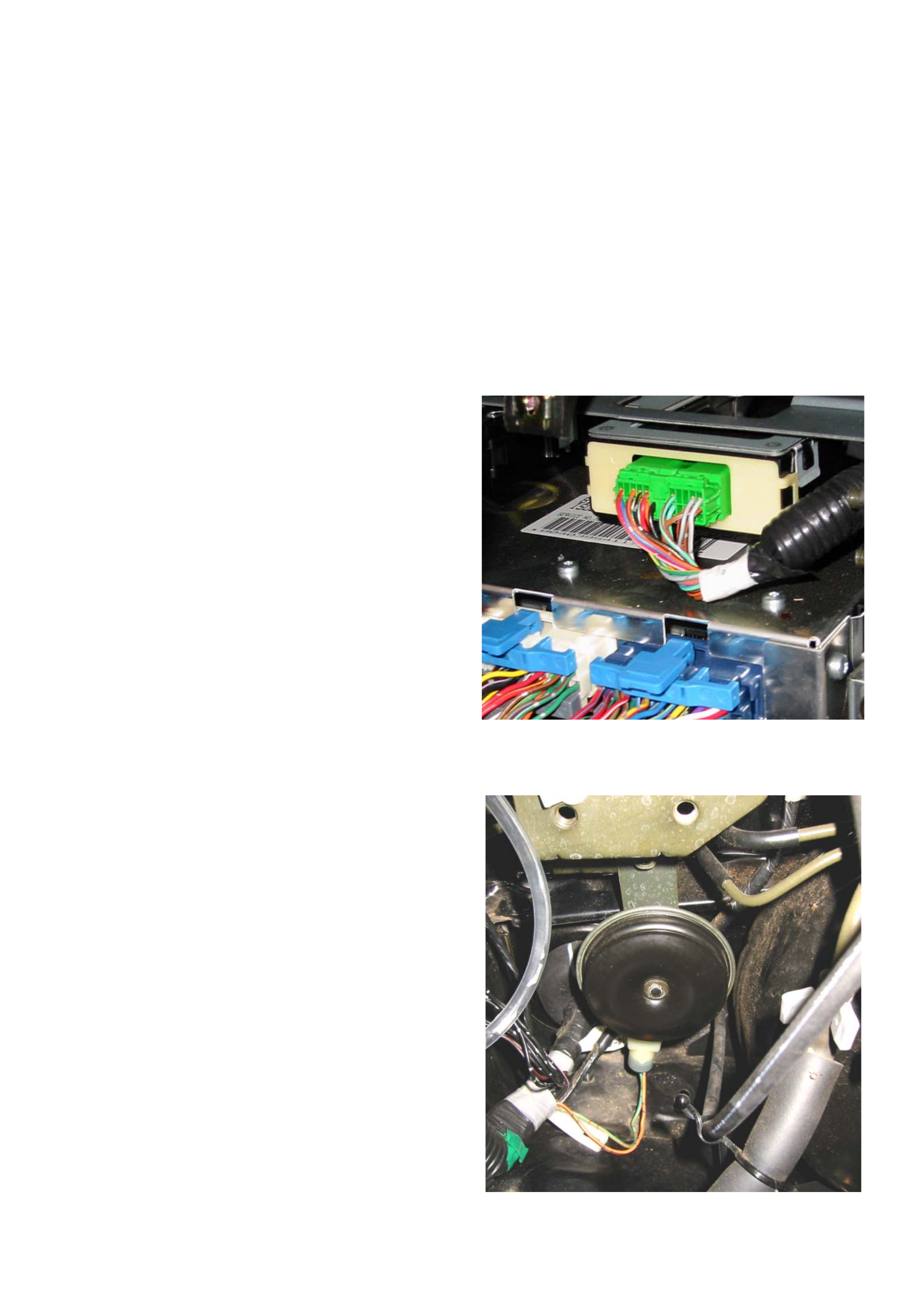
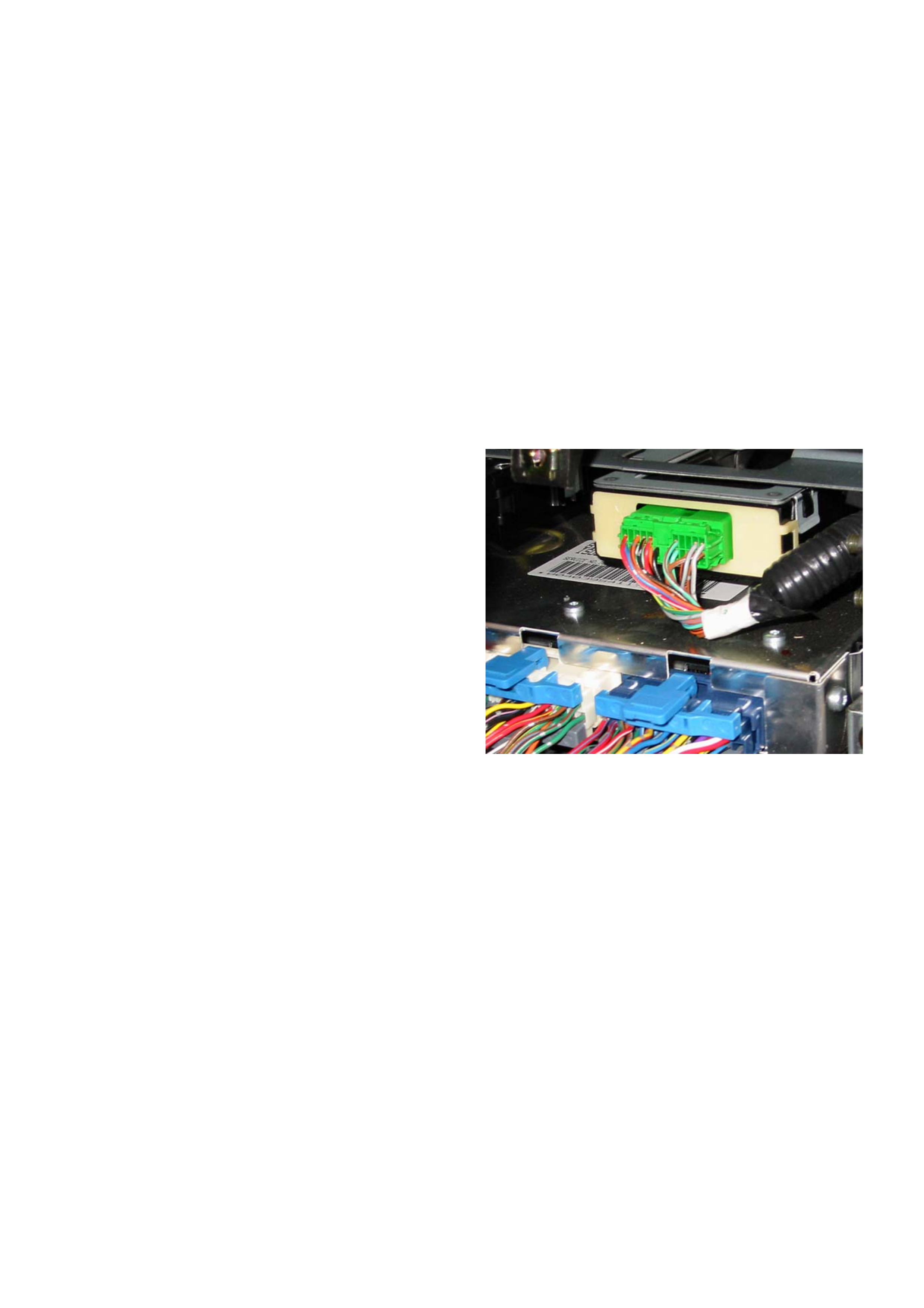
The Anti-theft control system is incorporated into the
Anti-theft/Keyless Entry Control Unit, which is mounted
in the lower centre of the instrument panel, and is
identified by a black ABS plastic casing and a green 22-
pin harness connector.
Removal
1. Disconnect the battery ground cable.
2. Remove the front console assembly - Refer to
Instrument Panel Assembly in Section 1-Body
and Hardware
3. Remove the lower cluster assmbly - Refer to
Instrument Panel Assembly in Section 1-Body
and Hardware
4. Disconnect the green harness connector.
5. Remove the four screws to remove the anti-theft
control unit and bracket
Installation
Follow the removal steps in reverse order.
Anti-theft Horn
The Anti-t heft horn is located on the bu lkhea d, betwee n
the brake booster and the inner guard.The anti-theft
horn is actuaten
Removal
1. Disconnect the battery ground cable.
2. Disconnect the connector and remove the fixing
bolt to remove the horn.
Installation
Follow the removal steps in reverse order.
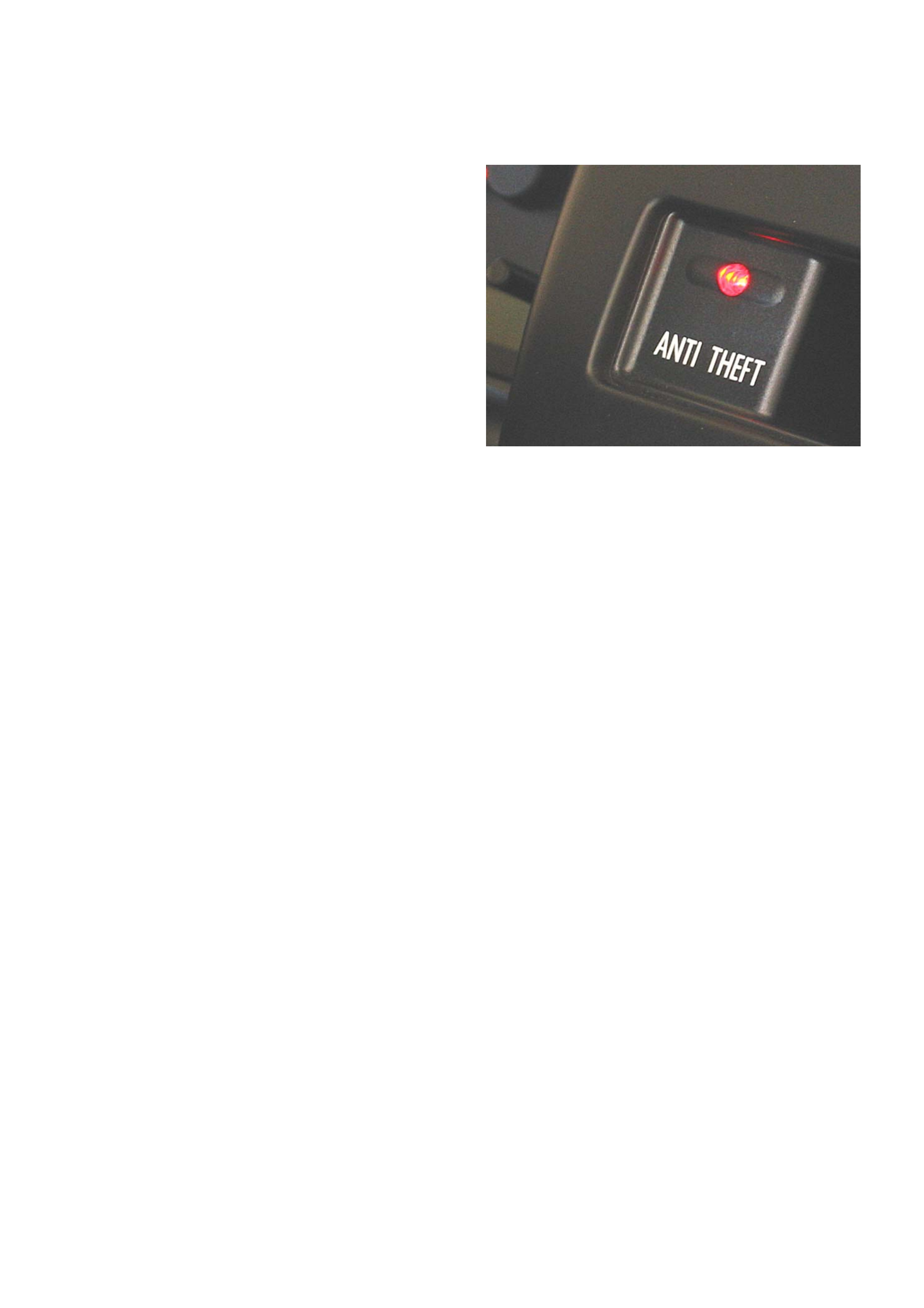
Anti-theft Indicator Lamp
The Anti-theft Indicator Lamp is located to the right of
the instrum ent cl uster.
When th e ignition key is tur ned to the “OFF” or “LOCK”
position or removed from the ignition switch, opening
any door will cause the Anti-theft Indicator Lamp to flash
once every 2 seconds.
Closing then locking all doors and the tailgate with the
mechanic al key or a remote key pad will cause the Anti-
theft Indicator Lamp to come “ON” steady for 10
seconds.
After 10 seconds, the Anti-theft Indicator Lamp will flash
once eve ry 1 s ec on d as a vis ua l indi ca tio n that the anti-
theft system is ‘armed’.
Removal
1. Disconnect the battery ground cable.
2. Remove the Front Console assembly - Refer to
Instrument Panel Assembly in Section 1-Body
and Hardware
3. Remove the Lower Cluster assmbly - Refer to
Instrument Panel Assembly in Section 1-Body
and Hardware
4. Remove the driver side lower Instrument Panel
assem bly - Re fer t o Inst r ume nt P ane l As se mbly
in Section 1-Body and Hardware
5. R emove th e Instr ument Pa nel Clu ster as sembly
- Refer to Instrument Panel Assembly in Section
1-Body and Hardware.
6. Remove the two screws holding the Anti-theft
Indicator Lamp in place.
Installation
Follow the removal steps in reverse order.
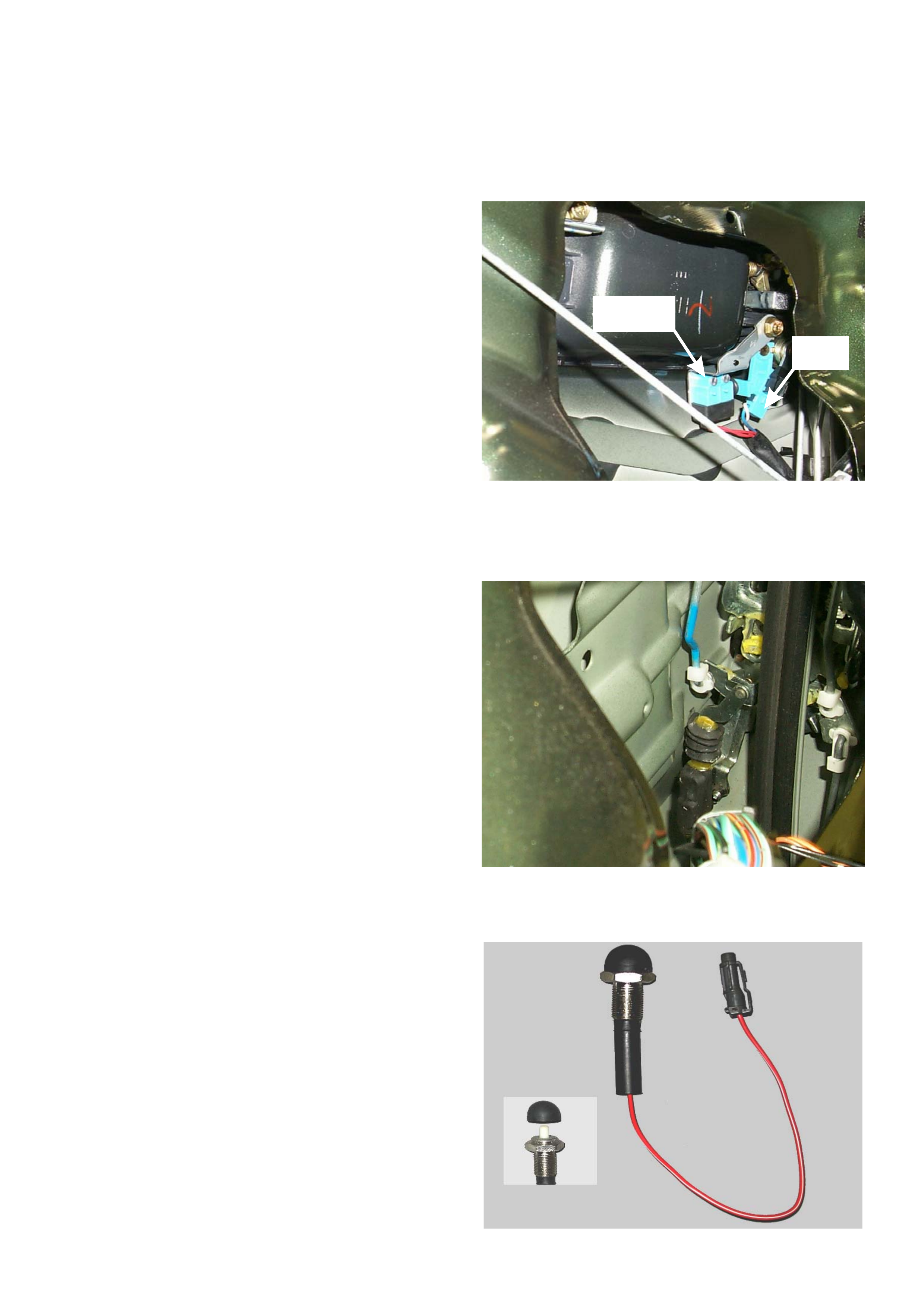
DOOR / TAILGATE / HOOD SWIT CHES
Front Door Key Switch
The Front Door Key Switch consists of two components:
•The Detect Switch - which, in conjunction with the
Front Door Lock Key Switch, provides the LOCK/
UNLOCK signal to the Anti-theft/Keyless Entry
Control Unit when the mechanical key is used. A 10
volt signal on pin 13 of the Anti-theft/Keyless Entry
Control Unit is pulled low as the lock cylinder is
turned.
•The Tamper Sw itch - pulls a 10 v olt signal at p in 16
of the Anti-theft/Keyless Entry Control Unit low if the
lock cylinder is forced from the door.
NOTE:
When refitting a Door Key Switch, ensure that the
switch is correctly adjusted as outlined in Section 1D -
Door Locks.
For removal/installation instructions, refer to Section 1D
- Door Locks.
Front Door Lock Key Switch
The Front Door Lock Key Switch supplies the LOCKED/
UNLOCKED signal to both the Anti-theft/Keyless Entry
Control U nit and the F ront Door Loc k & Power Wi ndow
Switch A ssembly wh en either the remote key pad or the
mechanical key is u sed.
A low-voltage signal is applied to pin 5 and 15 of the
Anti-theft/Keyless Entry Control Unit.
• Locking the doors will pull pin 5 low.
• Unlocking the doors will pull pin 15 low.
NOTE:
For removal/installation instructions, refer to Section 1D
- Door Locks.
Engine Hood Switch
The Engine Hood Switch supplies the HOOD OPEN
signal to the Anti-theft/Keyless Entry Control Unit when
the engine hood is either forcibly opened or the hood
release is actuated with the alarm set. This normally
open switch will pull Anti-theft/Keyless Entry Control
Unit pin 12 low when the hood opens.
Front Door
Key Sw itch Tamper
Switch
KEYLESS ENTRY
The basic c entral loc k ing syst em is co mmo n for all UBS
SE and Monterey models. The central locking system
can be operated by the mechanical keys, the door lock
buttons or the remote keypads.
The Keyless Entry system was introduced on MY1998
vehicl es . T he se v ehi cl es w er e i ni tia ll y su ppl ied w ith on e
remote keypad per vehicle (During 1999, an additional
keypad w as supplied, on own er r equ est, for al l MY 199 8
SE and Monterey models). All subsequent vehicles from
MY1999 have been supplied with two keypads.
COMPONENTS
Control Unit
The Keyless Entry circuit is incorporated into the Anti-
theft/Keyless Entry Control Unit, which is mounted in the
lower centre of the instrument panel, and is identified by
a black/beige ABS plastic casing and a green 22-pin
harness connector. Access to the control unit is gaine d
by removing the console and radio surround.
Power
The Keyless Entry Control Unit is powered via the 20
amp ‘Door Lock’ fuse (C-7), located in the I.P. fuse
panel. This fuse must be fitted during pre-delivery
inspect ion of the vehicle. F ailure of the fuse wi ll disabl e
the key-less entry function and door lock operation.
Synchronisation
The Anti-theft/Keyless Entry Control Unit must be
synchronised whenever the variable code from the
keypad is no longer detected by the control unit. This
usually occurs if a keypad button has been depressed
more than 255 times in succession without the Anti-
theft/Keyless Entry Control Unit being able to “adapt”
(i.e. not in the vicinity of the vehicle).
After removing the batteries, the remote control retains
the last variable code for a period of at least three
minutes. If this time is exceeded, the keypad and
control unit may need to be synchronised.
Synchronising Procedure
Turn the ignition “ON”
Within 30 seconds, press either keypad button.
Sucessful synchronisation is confirmed when the door
lock snibs actuate one time.
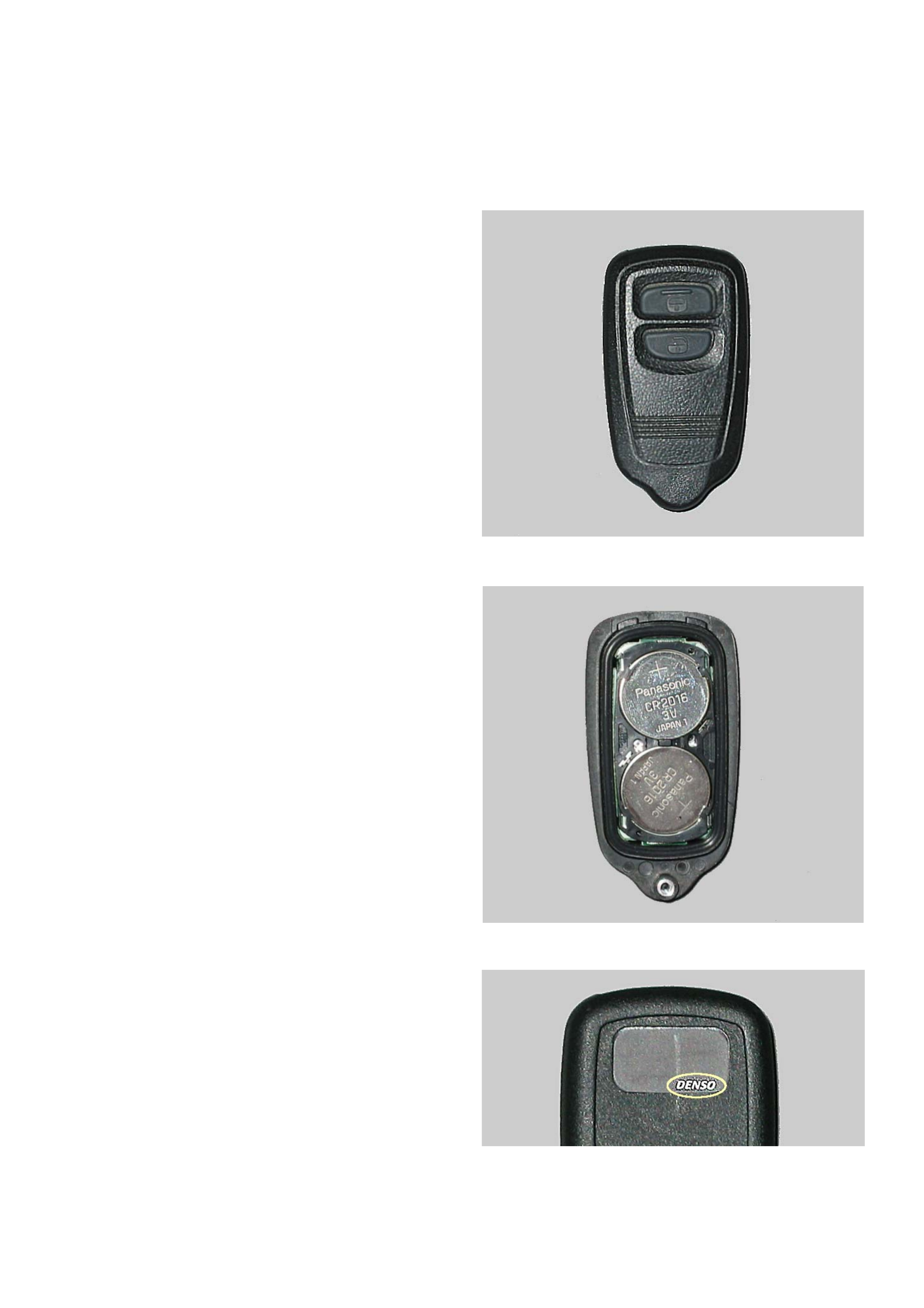
Remote Keypads
The remote keypad produces a multi-directional radio
signal (314Mhz @ 78dB) to activate the control circuit of
the Keyless Entry Control Unit.
Two remote keypads are supplied with the vehicle. A
maximum of four keypads can be programmed into the
Keyles s Entry Control Unit. Shoul d an attem pt be mad e
to program a fifth keypad, the first keypad code
programmed will be erased.
This variable code pattern has a complex structure to
prevent interception.When activated, each keypad will
produce three signals:
• A fixed code for identification by the control unit.
• A complex variable or “Rolling” code.
• A LOCK or UNLOCK command code.
Power
Each keypad is fitted with two lithium CR2016 battery
cells. Estimated service life of the two cells is at least
two years with an average usage of ten LOCK/UNLOCK
cycles per day.
Range
Minumum range of the keypad is specified at 10 metres,
althou gh this wil l vary with th e actua l operati ng envi ron-
ment (eg, close proximity to either radio or telephone
transmitting towers will reduce the effective range dra-
matically).
Keypad Types
Two part numbers have been issued for UBS Jackaroo
keypads:
8971638910 - Original issue with the commencement of
MY1998 production. Due to the electronic circuit char-
acteristics, it is necessary to depress the keypad but-
tons for at least 0.5 sec. in order for the Anti-theft/
Keyless Entry Control Unit to correcty identify the
request si gna l.
8972255231 - Second issue in September 1999. Fea-
tures revised internal circuitry to reducing keypad button
depression time to about 0.25 sec.
NOTE:
Keypads with the “DENSO” logo on the reverse side are
calibrated for the New Zealand market (304MHz @
78dB) are unsuitable for use with Australian market
vehicles.
Keypad Programming
Three keypad ID program modes are available:
1. ID Code New Registra tio n – erases all
programmed codes and registers new code.
2. ID Code Additional Registration – registers
additional ID codes.
3. ID Code Check – checks how many ID codes
are programmed in the module.

KEYPAD TESTING
As the keypad trans mits a F M radio si gnal, the v ehicle radi o can be used to check the operation of the key pad. The
actual frequency of the keypad may vary from 97MHz to 106MHz. It is best to commence testing with the radio set on
97Hz.
1. Turn the radio ‘ON’ and set the frequency to 97mHz, and the volume control at about ½ level.
2. Hold the keypad against the base of the antenna then press and hold down the keypad ‘lock’ button.
3. If a pulsing signal is heard from the speakers, the keypad is functioning.
4. Should you fail to hear a signal, try 98MHz and so on up to 106MHz.
5. If you have tried all the frequencies without hearing a signal, replace the two CR20 16 lithium cells in the keypad
and repeat the frequency test.

ID CODE ADDITIONAL REGISTRATION
• This procedure is carried out to program additional remote keypads into the system.
• The door opening and ignition key cycles should be commited to memory before attempting this procedure.
• A maximum of four keypads may be programmed into the system at any one time. Any attempt to exceed this will
result in the erasing of those keypads already programmed.
NOTE: Steps 2 – 6 must be performed within 15 seconds
NOTE:
1. If steps 2 – 6 are not completed within the specified time, the programming procedure will fail.
2. If the confimation response is not received at Step 7, the programming procedure has failed
3. Should the door lock snib cycle 3 times at any stage of this procedure, the module has aborted the programming
sequence
4. Steps 1 – 12 must be performed for each individual keypad
1ENSURE all doors are closed, the key is in the ignition switch & the ignition is in the OFF position.
2OPEN the driver door.
3CYCLE the ignition switch from ‘OFF’ — ‘ON’ — ‘OFF’ 3 times.
4CLOSE, then OPEN the driver door 2 times.
5CYCLE the ignition switch from ‘OFF’ — ‘ON’ — ‘OFF’ 3 times, and remove the key from the ignition switch.
6CLOSE, then OPEN the driver door 1 time.
7CONFIRM a ‘LOCK’ — ‘UNLOCK’ response from the driver door snib button.
8OPERATE the ‘LOCK’ and ‘UNLOCK’ buttons on the new keypad 3 times.
9CONFIRM a ‘LOCK’ — ‘UNLOCK’ response from the driver door snib button.
10 OPERATE the ‘LOCK’ and ‘UNLOCK’ buttons on the new keypad 2 times.
11 CONFIRM ‘LOCK’ — ‘UNLOCK’ responses by watching the driver door snib
12 The new keypad ID has been accepted

ID CODE NEW REGISTRATION
• This procedure should be carried out in the event of the loss of one or more keypads.
• The door opening and ignition key cycles should be commited to memory before attempting this procedure.
• A maximum of four keypads may be programmed into the system at any one time. Any attempt to exceed this will
result in the erasing of those keypads already programmed.
NOTE: Steps 2 – 6 must be performed within 15 seconds
NOTE:
1. If steps 2 – 6 are not completed within the specified time, the programming procedure will fail.
2. If the confimation response is not received at Step 7, the programming procedure has failed
3. Should the door lock snib cycle 3 times at any stage of this procedure, the module has aborted the programming
sequence
1ENSURE all doors are closed, the key is in the ignition switch & the ignition is in the OFF position.
2OPEN the driver door.
3CYCLE the ignition switch from ‘OFF’ — ‘ON’ — ‘OFF’ 3 times.
4CLOSE, then OPEN the driver door 2 times.
5CYCLE the ignition switch from ‘OFF’ — ‘ON’ — ‘OFF’ 5 times, and remove the key from the ignition switch.
6CLOSE, then OPEN the driver door 1 time.
7CONFIRM a ‘LOCK’ — ‘UNLOCK’ response from the driver door snib button.
8OPERATE the ‘LOCK’ and ‘UNLOCK’ buttons on the new keypad 3 times.
9CONFIRM a ‘LOCK’ — ‘UNLOCK’ response from the driver door snib button.
10 OPERATE the ‘LOCK’ and ‘UNLOCK’ buttons on the new keypad 2 times.
11 CONFIRM ‘LOCK’ — ‘UNLOCK’ responses by watching the driver door snib
12 The new keypad ID has been acceptedand the previous keypad ID’s have been erased
13 Program the remaining keypads using the Program Additional Keypads procedure

ID CODE CHECK
• This procedure is carried out to check how many remote keypads are programmed into the system.
• The door opening and ignition key cycles should be commited to memory before attempting this procedure.
• A maximum of four keypads may be programmed into the system at any one time. Any attempt to exceed this will
result in the erasing of those keypads already programmed.
NOTE: Steps 2 – 6 must be performed within 15 seconds
1ENSURE all doors are closed, the key is in the ignition switch & the ignition is in the OFF position.
2OPEN the driver door.
3CYCLE the ignition switch from ‘OFF’ — ‘ON’ — ‘OFF’ 3 times.
4CLOSE, then OPEN the driver door 2 times.
5CYCLE the ignition switch from ‘OFF’ — ‘ON’ — ‘OFF’ 1 time. DO NOT remove key from ignition switch
6CLOSE, then OPEN the driver door 1 time.
7The control unit will command two ‘LOCK’ — ‘UNLOCK’ responses from the driver door snib button, for
each transmitter programmed into the system

PROGRAMMING THE ANSWER-BACK FUNCTION - (MY1998-1999 ONLY)
• The same procedure is used to enable or disable the ‘Answer-back’ function.
• The door opening and ignition key cycles should be commited to memory before attempting this procedure.
NOTE: Steps 2 – 7 must be performed within 15 seconds
NOTE:
1. If steps 2 – 7are not completed within the specified time, the programming procedure will fail.
2. If the confimation response is not received at Step 8, the programming procedure has failed
3. Should the door lock snib cycle 3 times at any stage of this procedure, the module has aborted the programming
sequence
4. This procedure will only disable/enable the LOCK/UNLOCK chirp from the anti-theft horn. The illegal entry alarm
system will always be enabled.
1ENSURE all doors and the hood are closed, and the mechanical key is NOT in the ignition switch
2 INSERT the mechanical key in the drivers door lock
3Leaving the mechanical key in the drivers door lock, OPEN the driver door.
4CYCLE the mechanical key from ‘UNLOCK’ — ‘LOCK’ — ‘UNLOCK’ 3 times.
5CLOSE, then OPEN the driver door 2 times.
6CYCLE the mechanical key from ‘UNLOCK’ — ‘LOCK’ — ‘UNLOCK’ 3 times.
7CLOSE, then OPEN the driver door 1 time.
8CONFIRM a ‘LOCK’ — ‘UNLOCK’ response from the driver door snib button.
9The new setting for the ‘Answer-back’ function has been accepted.

Initial Diagnosis
When diagnosing a vehicle concern, it is important for the technician to have a basic understanding of the operation of
each system and be aware of the correct diagnostic procedures.
The diag nostic pr ocedur es are s pecific for each s ystem. F ailure to follow the correc t procedu re wil l result in lost ti me,
possible replacement of serviceable components and an aggrieved customer.
To determine which system is at fault, the technician must remember three very important points:
1. As the Anti-theft/Keyless Entry Control Unit provides the earth path for the starter motor relay (via the
Immobiliser Relay) a failure in either the Immobiliser System OR the Anti-theft/Keyless Entry Control Unit may
prevent the vehicle from cranking.
2. Except in exceptional circumstances, the Anti-theft Warning/Key-less Entry System cannot prevent the vehicle
from starting.
3. The Eng ine Immobiliser sy stem cannot prev en t the do or s fr om locking or unl ock ing via the r emo te k eypads or
the mechanical key.
Some ini tial ch ecks a nd a basi c knowledg e of the s ystem will assi st the tec hnician to narrow down the area in which
the fault has occurred. For example:
• Vehicle will not lock/unlock with the remote keypads
1. Does the dome light operate when a door is opened?
- If ‘NO’ check Fuse C16 and the dome light switch operation.
2. Does the vehicle lock/unlock with the mechanical key and the driver door switch?
- If ‘YES’ then the central locking system is functioning.
3. Can the alarm system be ‘armed’ with the mechanical key?
- ‘NO’ would indicate a possible incorrect door/engine hood input to the module.
- ‘YES’ would point to a keypad fault or failure of the relevant circuit within the module.
Having determined which system has failed, the correct diagnostic procedures can then be applied:
• Anti-Theft Alarm/Keyless Entry System diagnosis is performed by referring to the charts in this section.
• Engine Immobiliser system diagnosis is performed by referring to the procedures in Section 11 of the UBS Jackaroo
LCRV SIP.

Anti-Theft/Keyless Entry Harness Connector
PIN FUNCTION PIN FUNCTION
1 Passenger Front Door Switch 12 Engine Hood Switch
2 Passenger Rear Door Switch — Left & Right 13 Door/Tailgate Detect Switches
3 Not Used 14 Not Used
4 Not Used 15 Front Doo r Lock Sw. & Door Lock Key Sw.— UNLO CK
5 Front Door Lock Sw. & Door Lock Key Sw.— LOCK 16 Door/Tailgate Tamper Switches
6 Tailgate Door Switch 17 Ground - Behind Driver Side Kick-panel
7 Horn Relay 18 Power, ACC. (Ign. Sw.) — Fuse C13 10A Anti-theft
8 Anti-theft Horn 19 Ant i-th ef t Indi ca tor lam p
9 Not Used 20 Dome Lamp
10 Power, BATT.(+) — Fuse C16 10A Clock/Room 21 Anti-theft Relay Windings (Turn Signals — L and R)
11 Door Lock Motor Actuator Switches 22 Immobiliser Relay — Terminal 4

Anti-Theft/Keyless Entry Harness Pinout
Door Switches
Lock Switches
Power
Ground
Door Lock Key Switches
Door Lock Actuator Switch
Illegal Entry Indication
Anti-theft Indicator Lamp
Immobiliser Relay
PIN DOOR OPEN CLOSED
1 Passenger Front Less than 1.0ΩOpen Circuit
2 Rear Less than 1.0ΩOpen Circuit
6 Tailg ate Less than 1.0ΩOpen Circuit
12 Hood Less than 1.0ΩOpen Circuit
20 Driver Front Less than 1.0ΩMore than 5.0 volts
PIN SIGNAL REST LOCK UNLOCK
5 Doors — ‘LOCK’ Open Circuit Less than 2.0ΩOpen Circuit
15 Doors — ‘UNLOCK’ Open Circuit Open Circuit Less than 2.0Ω
PIN SOURCE VOLTAGE
10 Battery (+) — Fuse C16 Battery Voltage — Hot at all times
18 Ignition Switch (ACC) — Fuse C13 Battery Voltage — Ignition Key in ‘ACC’ position
PIN GROUND LOCATION RESISTANCE
17 Body - Behind Driver Side Kick-panel Less than 1.0Ω
PIN SIGNAL REST LOCK UNLOCK
13 Key Detect Open Circuit Less than 2.0ΩLess than 2.0Ω
16 Tamper Open Circuit Open Circuit Open Circuit
PIN SIGNAL LOCK UNLOCK
11 Actuator posi tio n Open Circuit Less than 2.0Ω
PIN SOURCE VOLTAGE
7 Horn Relay — Fuse F3 Battery Voltage — Hot at all times
8 Anti-theft Horn — Fuse F11 Battery Voltage — Hot at all times
21 Anti-theft Relay — Fuse F11 Battery Vo ltage — Ignition Key in ‘ACC’ position
PIN SIGNAL LAMP ‘ON’ LAMP ‘OFF’
19 Battery (+) — Fuse C18 0.2 volt Battery Voltage
PIN SIGNAL IGNITION ‘ON’ IGNITION ‘OFF’
22 Starter Relay Enable Less than 1.0 volt Less than 1.0 volt

Anti-theft System Check Procedure
Step Action Value(s) Yes No
1 1. Ensure the engine hood, tailgate and doors are
closed, and all windows are fully open.
2. Turn the Ignition “ON”. —Go to Step 2
2 1. Turn the Ignition “OFF” and remove the key from
the ignition switch.
Does the Anti-Theft indicator LED remain ‘OFF’? — Go to Step 3
Go to
Diagnostic
Procedure K
3 1. Inser t the key in the dr iver door lock and tu rn it to
the unlock (left) position. —Go to Step 4
4 1. Open the driver door.
Does the Anti-Theft indicator LED flash approx. once
every 2 seconds (LED will flash approx. 15 times)? — Go to Step 5
Go to
Diagnostic
Procedure A
5 Are the dome and courtesy lamps ‘ON’?
—Go to Step 6
Go to
Diagnostic
Procedure A
6Note: It is important to commence step 6 within 10
seconds of completing step 4.
1. Close the driver door.
2. Lock the driver door lock with the key.
Does the Anti-Theft indicator LED change from
flashing to constantly ‘ON’?
(LED will stay ‘ON’ constant for approx.10 seconds) — Go to Step 7
Go to
Diagnostic
Procedure B
7Note: It is important to commence step 7 within 10
seconds of completing step 6.
1. Unlock the drivers door with the snib button.
Does the Anti-Theft indicator LED change from
constantly ‘ON’ to ‘OFF’? — Go to Step 8
8 1. Lock the driver door with the lock snib button.
Does the Anti-Theft indicator LED change from ‘OFF’
to constantly ‘ON’?
(LED will stay ‘ON’ constantly for approx.10 seconds) — Go to Step 9
Go to
Diagnostic
Procedure B
9 1. Observe the Anti-Theft indicator LED.
Does the Anti-Theft indicator LED start to flash once
per second, 10 seconds after completing Step 8? — Go to Step 10
Go to
Diagnostic
Procedur e C
10 1. Unlock the driver door with the lock snib button.
Does the alarm operate (Indicators flashing and hor n
sounding intermittently)? — Go to Step 11
Go to
Diagnostic
Procedur e D
11 1. Inser t the key in the dr iver door l ock and tur n it to
the unlock (left) position.
Does the alarm stop? — Go to Step 12
Go to
Diagnostic
Procedure E
12 1. Lock the driver door lock with the key.
Does the Anti-Theft indicator LED change from ‘OFF’
to constantly ‘ON’? — Go to Step 13
Go to
Diagnostic
Procedure B

13 1. Observe the Anti-Theft indicator LED.
Does the Anti-Theft indicator LED start to flash once
per second, 10 seconds after completing Step 12? — Go to Step 14
Go to
Diagnostic
Procedur e C
14 1. Unlock the driver door lock with the key.
Does the alarm remain inactive? — Go to Step 15
Go to
Diagnostic
Procedure F
15 1. Lock the driver door lock with the key.
Does the Anti-Theft indicator LED change from ‘OFF’
to constantly ‘ON’?
(LED will stay ‘ON’ constantly for approx.10 seconds) — Go to Step 16
Go to
Diagnostic
Procedure B
16 1. Observe the Anti-Theft indicator LED.
Does the Anti-Theft indicator LED start to flash once
per second, 10 seconds after completing Step 15? — Go to Step 17
Go to
Diagnostic
Procedur e C
17 1. Unlock the dri ver side rear door with the lock snib
button.
Does the alarm operate (Indicators flashing and hor n
sounding intermittently)? — Go to Step 18
Go to
Diagnostic
Procedur e D
18 1. Unlock the driver door lock with the key.
Does the alarm stop? — Go to Step 19
Go to
Diagnostic
Procedure E
19 1. Open the driver side rear door.
Does the Anti-Theft indicator LED flash approx. once
every 2 seconds (LED will flash approx. 15 times)? — Go to Step 20
Go to
Diagnostic
Procedure A
20 Are the dome and courtesy lamps ‘ON’?
—Go to Step 21
Go to
Diagnostic
Procedure A
21 Note: It is important to commence step 21 within
10 seconds of completing step 19.
1. With one person in the rear of the vehicle, close
the driver side door.
2. Lock the driver door lock with the key.
Does the Anti-Theft indicator LED change from
flashing to constantly ‘ON’?
(LED will stay ‘ON’ constantly for approx.10 seconds) — Go to Step 22
Go to
Diagnostic
Procedure B
22 Note: It is important to commence step 22 within
10 seconds of completing step 21.
1. Unlock the driver side rea r door lock with th e lock
snib.
Does the Anti-Theft indicator LED change from
constantly ‘ON’ to ‘OFF’? — Go to Step 23
Go to
Diagnostic
Procedur e C
23 1. Lock the driver side rear door with the lock snib.
Does the Anti-Theft indicator LED change from ‘OFF’
to constantly ‘ON’’?
(LED will stay ‘ON’ constantly for approx.10 seconds) — Go to Step 24
Go to
Diagnostic
Procedure B
Step Action Value(s) Yes No

24 1. Observe the Anti-Theft indicator LED.
Does the Anti-Theft indicator LED start to flash once
per second, 10 seconds after completing Step 23? — Go to Step 25
Go to
Diagnostic
Procedur e C
25 1. Unlock the tailgate with the lock snib button.
Does the alarm operate (Indicators flashing and hor n
sounding intermittently)? — Go to Step 26
Go to
Diagnostic
Procedur e D
26 1. Insert the key in the tail gate lock and tu r n it to the
unlock (right) position.
Does the alarm stop? — Go to Step 27
Go to
Diagnostic
Procedur e H
27 1. Open the tailgate
Does the Anti-Theft indicator LED flash approx. once
every 2 seconds (LED will flash approx. 15 times)? — Go to Step 28
Go to
Diagnostic
Procedure A
28 Is the luggage compartment lamp ‘ON’? (luggage
compartment lamp switch must be in the ‘door’
position) — Go to Step 29
Go to
Diagnostic
Procedure G
29 Note: It is important to commence step 29 within
10 seconds of completing step 27.
1. Close the tailgate.
2. Lock the tailgate lock with the key.
Does the Anti-Theft indicator LED change from
flashing to constantly ‘ON’?
(LED will stay ‘ON’ constantly for approx.10 seconds) — Go to Step 30
Go to
Diagnostic
Procedure B
30 1. Observe the Anti-Theft indicator LED.
Does the Anti-Theft indicator LED start to flash once
per second, 10 seconds after completing Step 29? — Go to Step 31
Go to
Diagnostic
Procedur e C
31 1. Unlock the tailgate lock with the key
Does the alarm remain inactive? — Go to Step 32
Go to
Diagnostic
Procedure F
32 1. Lock the tailgate lock with the key.
Does the Anti-Theft indicator LED change from ‘OFF’
to constantly ‘ON’?
(LED will stay ‘ON’ constantly for approx.10 seconds) — Go to Step 33
Go to
Diagnostic
Procedure B
33 1. Observe the Anti-Theft indicator LED.
Does the Anti-Theft indicator LED start to flash once
per second, 10 seconds after completing Step 32? — Go to Step 34
Go to
Diagnostic
Procedur e C
34 1. Unlock the passe nger side rear door with the lock
snib button
Does the alarm operate (Indicators flashing and hor n
sounding intermittently)? — Go to Step 35
Go to
Diagnostic
Procedur e D
35 1. Insert the key in the passenger side front door lock
and turn it to the unlock (right) position.
Does the alarm stop? — Go to Step 36
Go to
Diagnostic
Procedure E
Step Action Value(s) Yes No

36 1. Open the passenger side rear door.
Does the Anti-Theft indicator LED flash approx. once
every 2 seconds (LED will flash approx. 15 times)? — Go to Step 37
Go to
Diagnostic
Procedure A
37 Are the dome and courtesy lamps ‘ON’?
—Go to Step 38
Go to
Diagnostic
Procedure A
38 Note: It is important to commence step 38 within
10 seconds of completing step 36.
1. Close the passenger side rear door.
2. Lock the passenger side front door lock with the
key.
Does the Anti-Theft indicator LED change from
flashing to constantly ‘ON’?
(LED will stay ‘ON’ constantly for approx.10 seconds) — Go to Step 39
Go to
Diagnostic
Procedure B
39 1. Observe the Anti-Theft indicator LED.
Does the Anti-Theft indicator LED start to flash once
per second, 10 seconds after completing Step 38? — Go to Step 40
Go to
Diagnostic
Procedur e C
40 1. Unlock the pa sseng er s ide fr ont doo r with the l ock
snib button.
Does the alarm operate (Indicators flashing and hor n
sounding intermittently)? — Go to Step 41
Go to
Diagnostic
Procedur e D
41 1. Unlock the pa sseng er s ide fr ont doo r lock with th e
key.
Does the alarm stop? — Go to Step 42
Go to
Diagnostic
Procedure E
42 1. Open the passenger side front door.
Does the Anti-Theft indicator LED flash approx. once
every 2 seconds (LED will flash approx. 15 times)? — Go to Step 43
Go to
Diagnostic
Procedure A
43 Are the dome and courtesy lamps ‘ON’?
—Go to Step 44
Go to
Diagnostic
Procedure A
44 Note: It is important to commence step 44 within
10 seconds of completing step 42.
1. Close the passenger side front door.
2. Lock the passenger side front door lock with the
key.
Does the Anti-Theft indicator LED change from
flashing to constantly ‘ON’?
(LED will stay ‘ON’ constantly for approx.10 seconds) — Go to Step 45
Go to
Diagnostic
Procedure B
45 1. Observe the Anti-Theft indicator LED.
Does the Anti-Theft indicator LED start to flash once
per second, 10 seconds after completing Step 44? — Go to Step 46
Go to
Diagnostic
Procedur e C
46 1. Unlock the pa sseng er s ide fr ont doo r lock with th e
key.
Does the alarm remain inactive? — Go to Step 47
Go to
Diagnostic
Procedure F
Step Action Value(s) Yes No

47 1. Lock the passenger side front door lock with the
key.
Does the Anti-Theft indicator LED change from ‘OFF’
to constantly ‘ON’?
(LED will stay ‘ON’ constantly for approx.10 seconds) — Go to Step 48
Go to
Diagnostic
Procedure B
48 1. Observe the Anti-Theft indicator LED.
Does the Anti-Theft indicator LED start to flash once
per second, 10 seconds after completing Step 47? — Go to Step 49
Go to
Diagnostic
Procedur e C
49 1. Open the engine hood with the hood release lever.
Does the alarm operate (Indicators flashing and hor n
sounding intermittently)? — Go to Step 50
Go to
Diagnostic
Procedure I
50 1. Insert the key in the ignition switch and turn the
switch to the ‘ACC’ position.
Does the alarm stop? — Go to Step 51
Go to
Diagnostic
Procedure J
51 1. Unlock doors with remote key pad.
Are all doors unlocked? —Go to Step 52 Refer to Keypad
Testing
52 1. Lock doors with remote key pad.
Are all doors locked —
A/Theft System
is functioning
correctly. Refer to Keypad
Testing
Step Action Value(s) Yes No

Anti-Theft System Diagnostic Procedure Chart
ITEM MALFUNCTION POSSIBLE CAUSE DETECTING METHOD
AAnti-Theft LED does not flash Defective door switch or open
circuit in wiring harness With the door open, the dome light and
courtesy lights do not come ON
Short to ground in detect switch Check at the control unit harness
connector
BIndicator light does not
change to fully ‘ON’
condition, or does not
comes on at all
Hood, doors or tailgate not fully
closed and locke d Check closure and lock
Defective door switch or a short
to ground in switch wiring The dome light and courtesy lights
remain ON after closing the vehicle
Defective tamper switch or a
short to ground in switch wiring Check at the control unit harness
connector
Defective lock switch or a short
to ground in switch wiring Check at the control unit harness
connector
Defectiv e hood s witch or a sh ort
to ground in switch wiring Defective tamper switch or a short to
ground in switch wiring
Defective tailgate switch or a
short to ground in switch wiring The “luggage room” light remains ON
after closing the vehicle
CAnti-Thef t LED remains in a
constant ‘ON’ state. Defective Control Unit Replace with known good unit
DThe alarm does not operate
when the door is opened by
pulling up the locking snib
button
Poor loc k sw itc h c ontact o r open
circuit in switch wiring Check at the control unit harness
connector
Blown fuse, open circuit to haz-
ard warning l amps and anti-the ft
horn
Check at the control unit harness
connector
EAlarm will not turn OFF Defective contact of Detect
switch or damage d switch wiring Check at the control unit harness
connector
FAlarm operates when the
door is opened with the
mechanical key
Defective Detect switch or dam-
aged switch wiring Check at the control unit harness
connector
Detect switch is incorrectly
adjusted When the key is turned to the LOCK
position, the alarm stops
GThe alarm does not operate
when the tailgate is opened Defective tailgate switch or dam-
aged switch wiring When the “luggage room” is turned
ON, the l ight does not come ON when
the tailgate is opened.
HThe alarm does not stop
when the tailgate is opened
with the mechanical key
Defective tailgate detect switch
or damaged switch wiring Check at the control unit harness
connector
Tailgate Detect switch is incor-
rectly adjusted When the key is turned to the LOCK
position, the alarm stops

Anti-Theft System Diagnostic Procedure Chart
ITEM MALFUNCTION POSSIBLE CAUSE DETECTING METHOD
IThe alarm does not operate
when the hood is opened Damaged hood switch or open
circuit in wiring harness Check at the control unit harness
connector
JThe alarm does not stop
when the ignition is turned
ON
Defective ignition switch or wir-
ing h arness o r blown ‘A CC’ fuse
C-11
With the ignition switch in the ‘ACC’
position, the radio, lighter and door
mirrors do not operate
Blown Anti-Theft fuse C-13 With the ignition switch in the ‘ACC’
position, the radio, lighter and door
mirrors operate
KAnti-Theft LED flashes
continually
Damaged door switch or short to
ground in wiring harness Dome light and courtesy lights remain
ON with the door closed
Damaged door switch or short to
ground in wiring harness Check at the control unit harness
connector

SYSTEM WIRING CIRCUITS
The Anti-theft/Keyless Entry System shares a number of components and circuits with both the Interior Lighting
System an d the Door Lock Syst em. It may ther efore be necessa ry to refer to all thr ee wiring circuits when per forming
system faul t diagnos is .
MY1998-1999 — Refer to:
1. Section 12B1 - Anti-theft System Wiring - with Keyless Entry
2. Section 12B1 - Interior Lighting System
3. Section 12B1 - Door Lock System - with Keyless Entry
MY2000-ON — Refer to:
1. Section 12B2 - Anti-theft System Wiring - with Keyless Entry
2. Section 12B2 - Interior Lighting System
3. Section 12B2 - Door Lock System - with Keyless Entry