
CAUTION
When fasteners are removed, always
reinstall them at the same location from
which they were removed. If a fastener
needs to be replaced, use the correct part
number fastener for that application. If the
correct part number fastener is not available,
a fastener of equal size and strength (or
stronger) may be used.
Fasteners that are not reused, and those
requiring thread locking compound, will be
called out. The correct torque values must
be used when installing fasteners that
require it. If the above conditions are not
followed, parts or system damage could
result.
SECTION 2A - HEATING AND VENTILATION
General Description
Heater
Control Lever Assembly
Ventilation
Air Select Knob
Air Source Select Lever
Fan Control Knob
Temperature Control Knob
Ceramic Heater
On-Vehicle Service
Heater Unit
Heater Core and/or Mode Door
Heater Mode Control Link Unit
Heater Temperature Control Link Unit
Blower Assembly
Blower Link Unit and/or Mode Door
Blower Motor
Rear Heater Duct, Defroster Nozzle and Ventilation Duct
Center and/or Side Vent
Control Lever Assembly and/or Control Cables
Control Panel Illumination Bulb
Resistor
When the engine warming up, the warmed engine
coolant is sent out into the heater core. The heater
system supplies warm air into the passenger
compartment to warm it up.
Outside air is circulated through the heater core of
the heater unit and then back into the passenger
compartment. By controlling the mixture of outside
air and heater core air, the most comfortable
passenger compartment temperature can be
selected and maintained.
The temperature of warm air sent to the passenger
compartment is controlled by the temperature
control knob. This knob acts to open and close the
air mix door, thus controlling the amount of air
passed through the heater core.
The air select knob, with its different modes, also
allows you to select and maintain the most
comfortable passenger compartment temperature.
The air source select lever is used to select either
“FRESH” for the introduction of the outside air, or
“CIRC” for the circulation of the inside air. When
the lever is set to “FRESH”, the outside air is always
taken into the passenger compartment. When
setting the lever to “CIRC” position, the circulation
of air is restricted only to the inside air with no
introduction of the outside air and the air in the
passenger compartment gets warm quickened.
However, the lever is normally set to “FRESH” to
prevent the windshield from clouding.
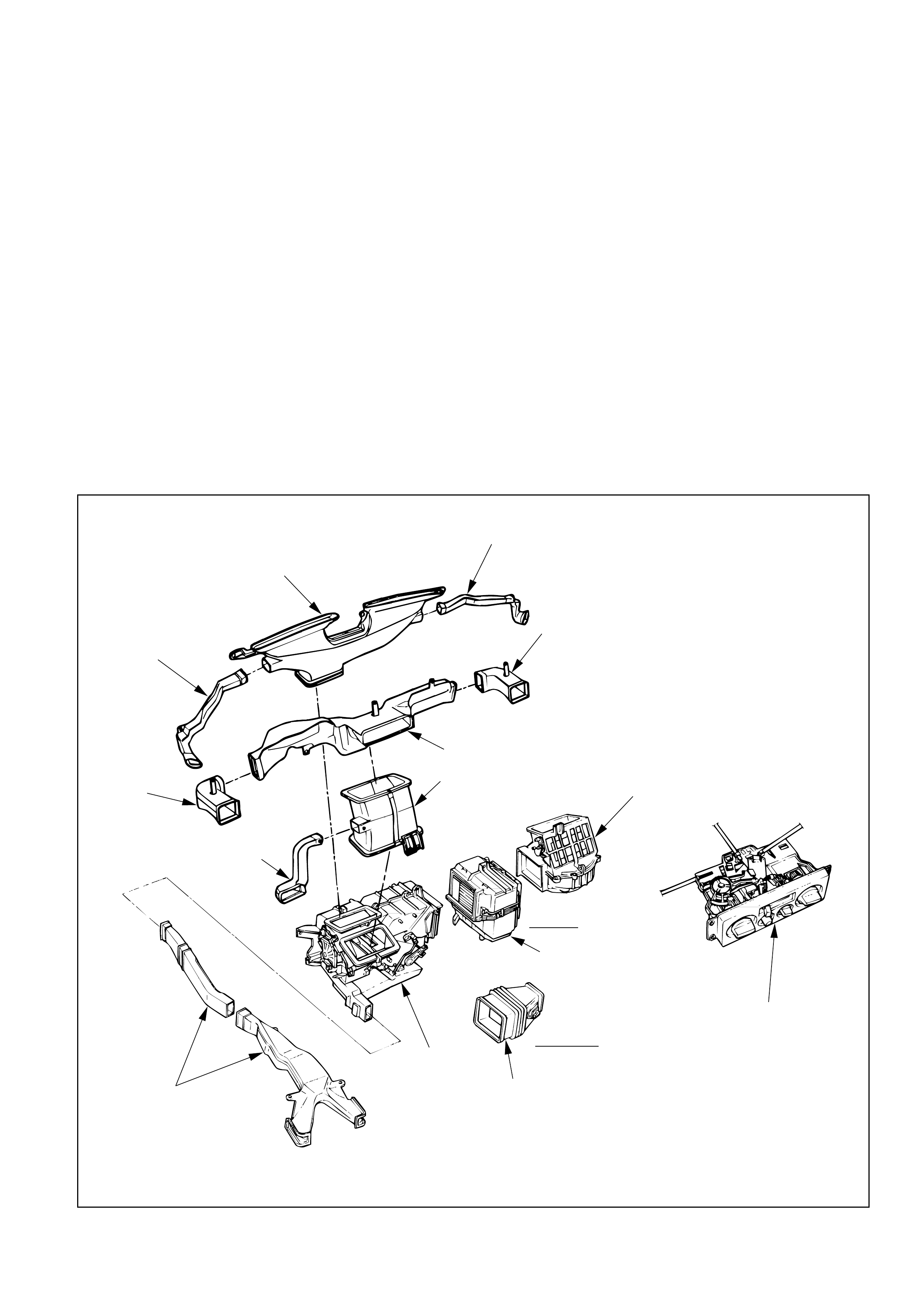
GENERAL DESCRIPTION
HEATER
Side def hose
Vent box
Upper center vent duct
Lower center
vent duct Blower assembly
Control lever assembly
Evaporator
assembly
W/A/C
W/O A/C
Duct
Heater unit
Lap vent nozzle
Vent box
Side def hose
Defroster nozzle
Rear heater duct
A/C - Air Conditioning
This illustration is based on LHD
This illustration is based on LHD
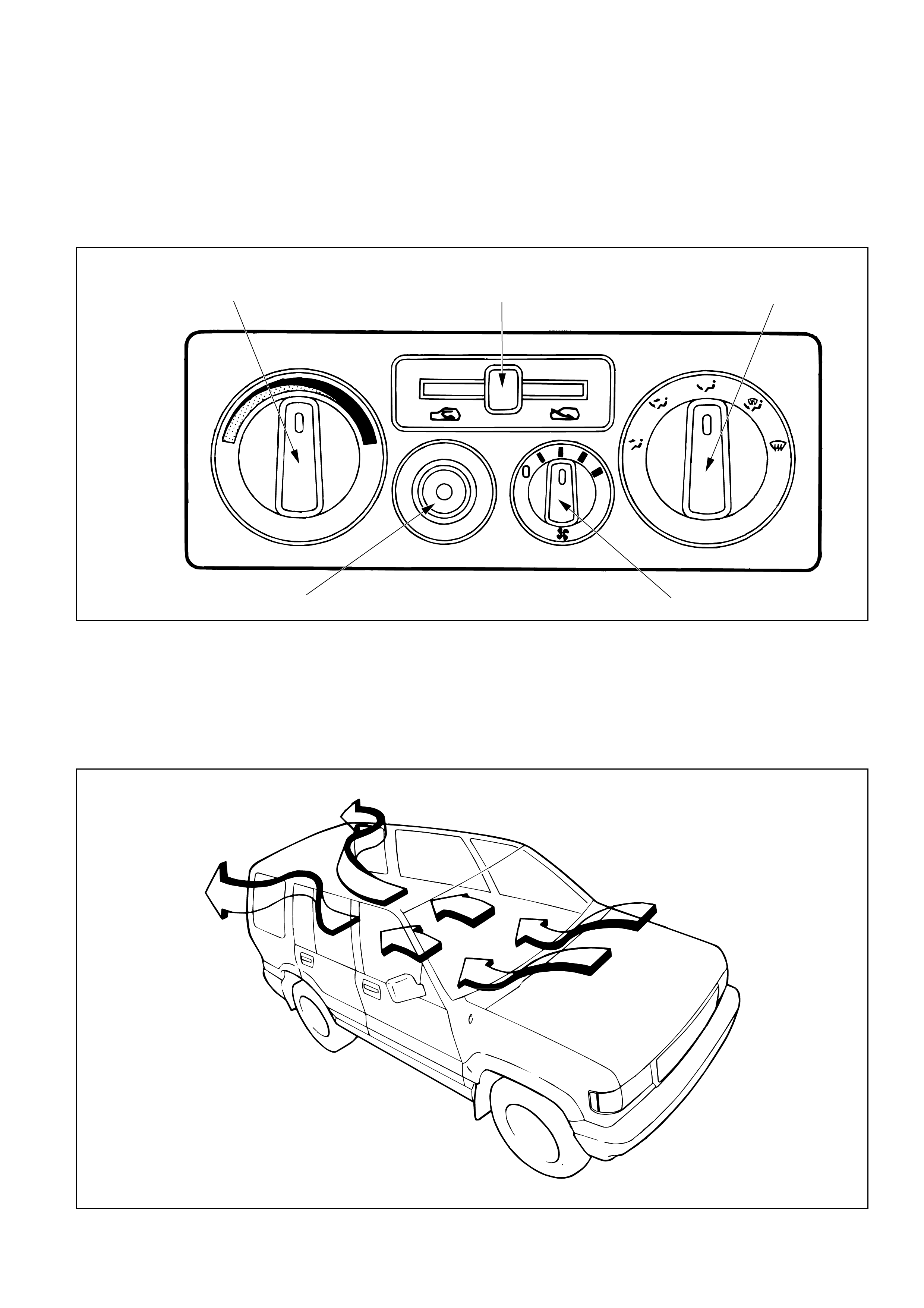
Temperature control knob
A/C switch (W/A/C)
TEMP
A/C
Fan control knob(Fan switch)
Air source select lever Air select knob
The vehicle has cable-control-type to control by
cable the mode and temperature of the heater unit
and the mode door for the air source of the blower
assembly.
The fan control is used to control the amount of air
sent out by the resistor at four levels from “LOW”
to “HIGH”.
CONTROL LEVER ASSEMBLY
VENTILATION
Set “AIR SOURCE SELECT LEVER” to “FRESH”
position and turn on the blower fan. Heating can be
done in this lever position, sending in fresh air from
outside.
The blower fan also serves to deliver fresh outside
air to the vehicle interior to assure adequate
ventilation.
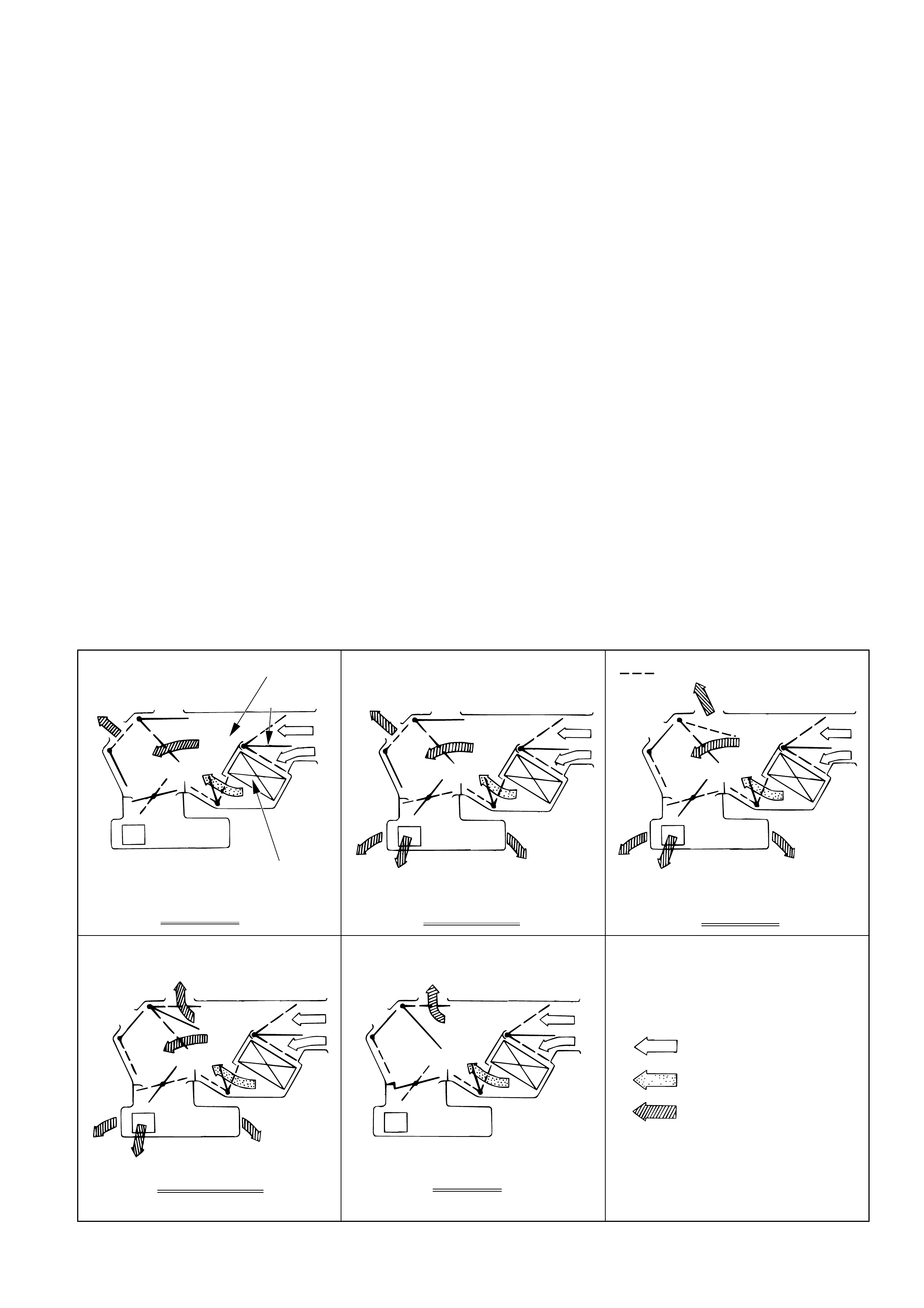
AIR SELECT KNOB
The air selector knob allows you to direct heated air
into the passenger compartment through different
outlets.
1. Vent - In this position, air is discharged from
the upper air outlet. Air quantity is controlled
by the fan control knob.
2. Bi-Level - In this position, air flow is divided
between the upper air outlets and the foot air
outlets, with warmer air delivered to the floor
outlets than the air delivered to the upper air
outlets.
3. Foot - In this position, air flow is delivered to
the foot while sending approx. 30% of total
amount of air to the windshield
4. Def/Foot - In this position, air flow is delivered
to the foot, while sending approx. 40% of total
amount of air to the windshield.
5. Defrost - In this position, most of the air is
delivered to the windshield and a small
amount is delivered to the side windows.
Moving the air source select lever to the “CIRC”
position provides quickest heat delivery by closing
the blower assembly mode door. In this position,
outside air is not delivered to the passenger
compartment.
AIR SOURCE SELECT LEVER
The intake of outside air and the circulation of inside
air are controlled by sliding this lever left or right.
FAN CONTROL KNOB
This knob controls the blower motor speed to
regulate the amount of air delivered to the defrost,
foot, and ventilation ducts:
1. Low
2. Medium Low
3. Medium High
4. High
TEMPERATURE CONTROL KNOB
When the temperature control knob is in the
“COLD” position, the air mix door closes to block
the flow of air to the heater core.
When the temperature control knob is in the
“HOT” position, the air mix door opens to allow air
to pass through the heater core and heat the
passenger compartment.
Placing the knob in an intermediate position will
cause a lesser or greater amount of air to reach the
heater core. In this mode the passenger compart-
ment temperature can be regulated.
Heater core
Heater unit
TO VENT OUTLET Air mix door
VENT MODE
TO FOOT
TO VENT OUTLET
BI-LEVEL MODE
FOOT MODE
TO FOOT OUTLET
TO DEF OUTLET(LHD)
DEF/FOOT MODE
TO FOOT OUTLET
TO DEF OUTLET
DEF MODE
TO DEF OUTLET
: COLD AIR
: HOT AIR
: TEMP.CONTROLLED AIR
Full hot switch
Ceramic heater
Heater unit
CERAMIC HEATER
When the fan control knob (fan switch) turns on with the temperature control knob set to “FULL HOT” (full
hot switch “ON”), the ceramic heater in the heater unit gets hot, thus causing the heater blow temperature
of diesel vehicle to get high to improve the heating performance (Since the engine coolant temperature of
diesel vehicle is low, its blow temperature is also low.).
Glow plug
Full hot switch
Fan switch
Thermo switch
Less than 80°C (177.8°F)
CERAMIC HEATER
“ON”CERAMIC HEATER
“OFF”
OFF
ON
OFF
OFF
OFF
ON
ON
ON
This illustration is based on RHD
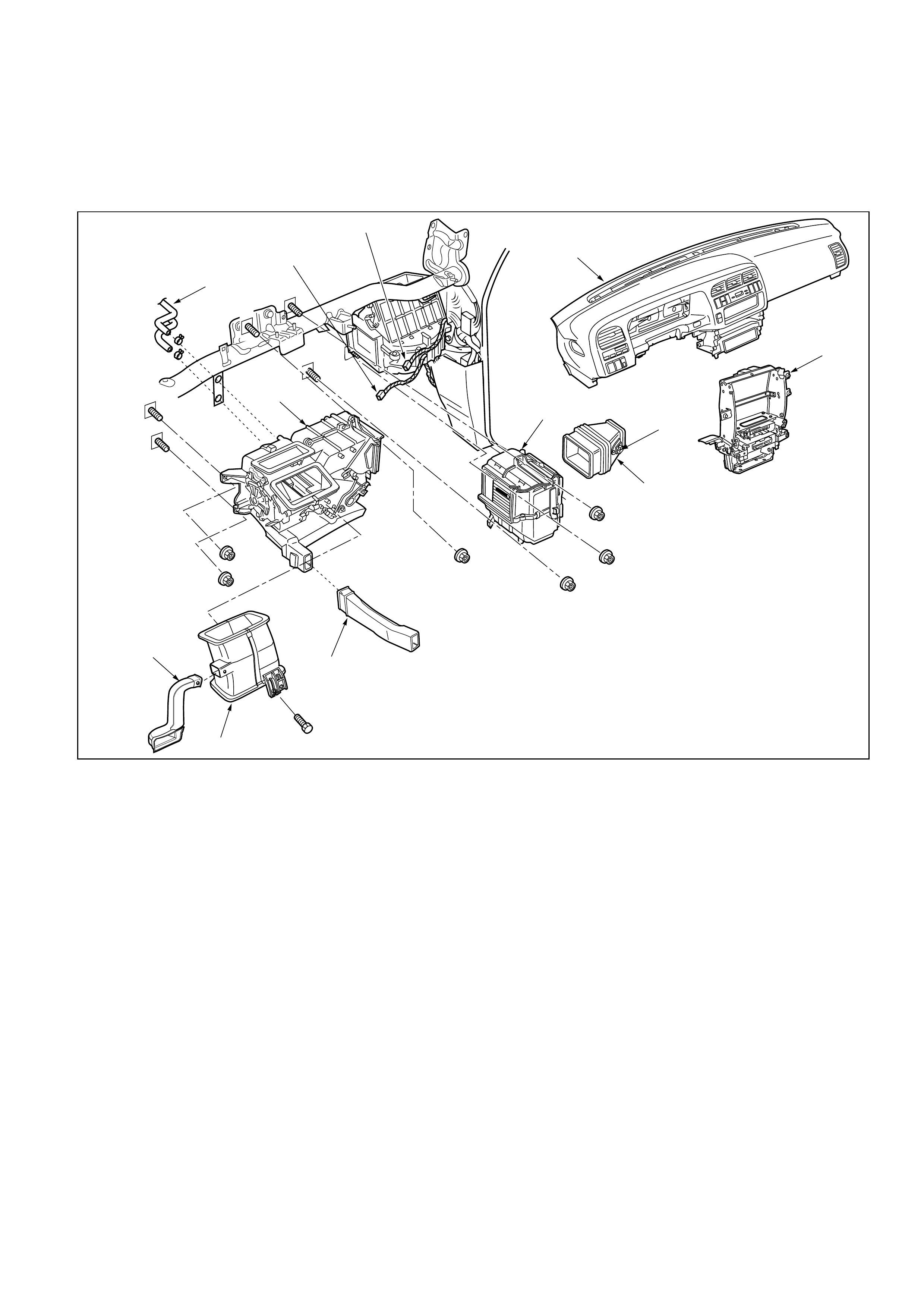
ON-VEHICLE SERVICE
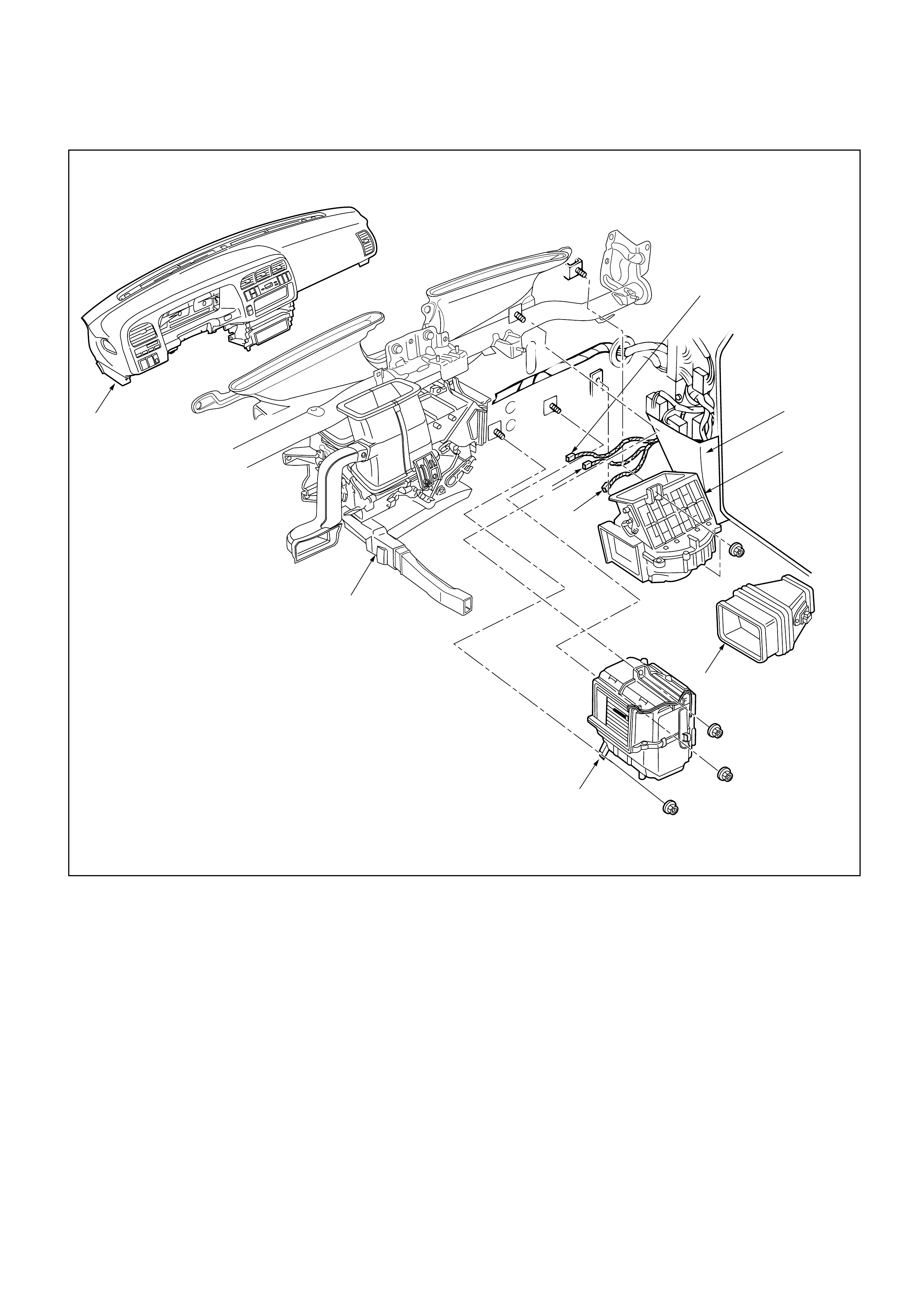
HEATER UNIT
4a
5
3
4
2
6
9
8
7
1
Electro thermo connector (With A/C)
Resistor
Removal Steps
1. Instrument panel assembly
2. Water hose
3. Resistor connector
4. Duct
4a. Evaporator assembly (A/C only)
5. Instrument panel center bracket
6. Rear heater duct
7. Heater unit
8. Lap vent nozzle
9. Center ventilation lower duct
Installation Steps
To install, follow the removal steps in the
reverse order
This illustration is based on LHD

INSTALLATION
To install, follow the removal steps in the reverse order,
noting the following points:
1. When handling the ECM and the control unit, be
careful not to make any improper connection of the
connectors.
2. Adjust control lever assembly cables.
Refer to “CONTROL LEVER ASSEMBLY” installation
steps in this section.
3. When installing the heater unit, defroster nozzle and
center vent duct, be sure that proper seal is made,
without any gap between then.
REMOVAL
Preparation:
• Disconnect the battery ground cable
• Drain engine coolant
• Discharge and recover refrigerant (W/A/C)
(Refer to Section 2B “REFRIGERANT RECOVERY”)
1. Instrument Panel Assembly
Refer to Section 1 “BODY” for INSTRUMENT PANEL
ASSEMBLY removal procedure.
2. Water Hose
Disconnect water hoses at heater unit.
3. Resistor Connector
4. Duct
4a. Evaporator Assembly
Refer to Section 2B “AIR CONDITIONING” for
Evaporator Assembly removal procedure.
5. Instrument panel center bracket
6. Rear Heater Duct
7. Heater Unit
8. Lap vent nozzle
9. Center ventilation lower duct
Removal Steps
1. Heater unit
2. Duct
3. Case (Mode control)
4. Case (Temperature control)
5. Heater core
6. Mode door
Installation Steps
To install, follow the removal steps in the
reverse order.
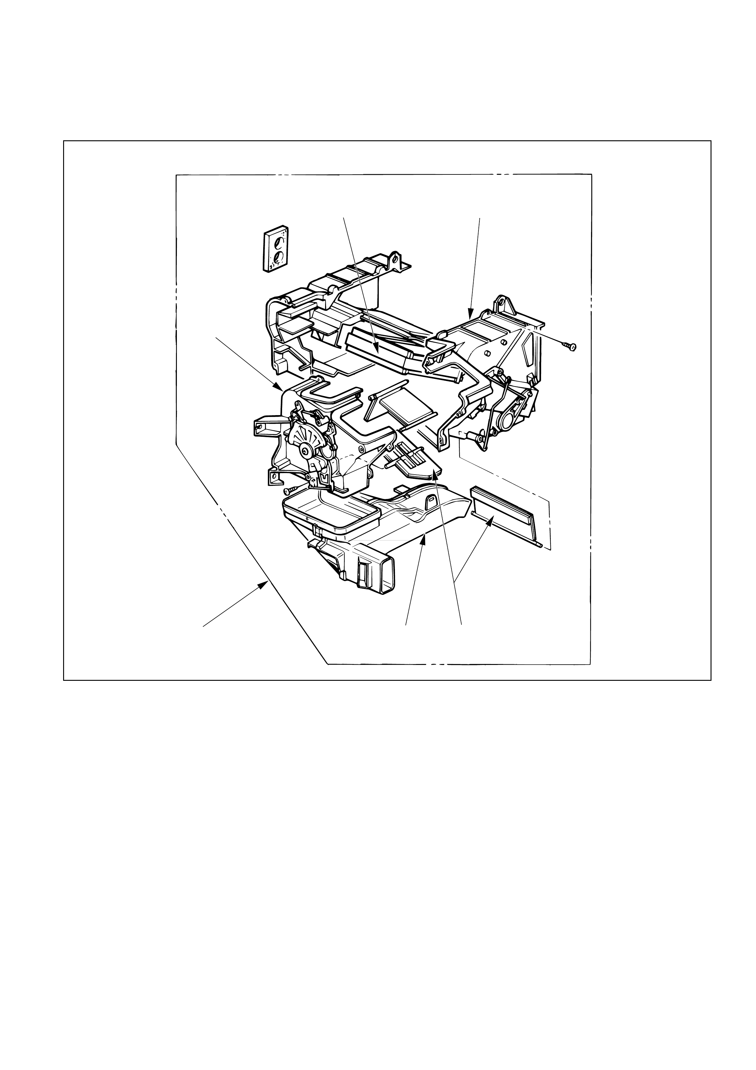
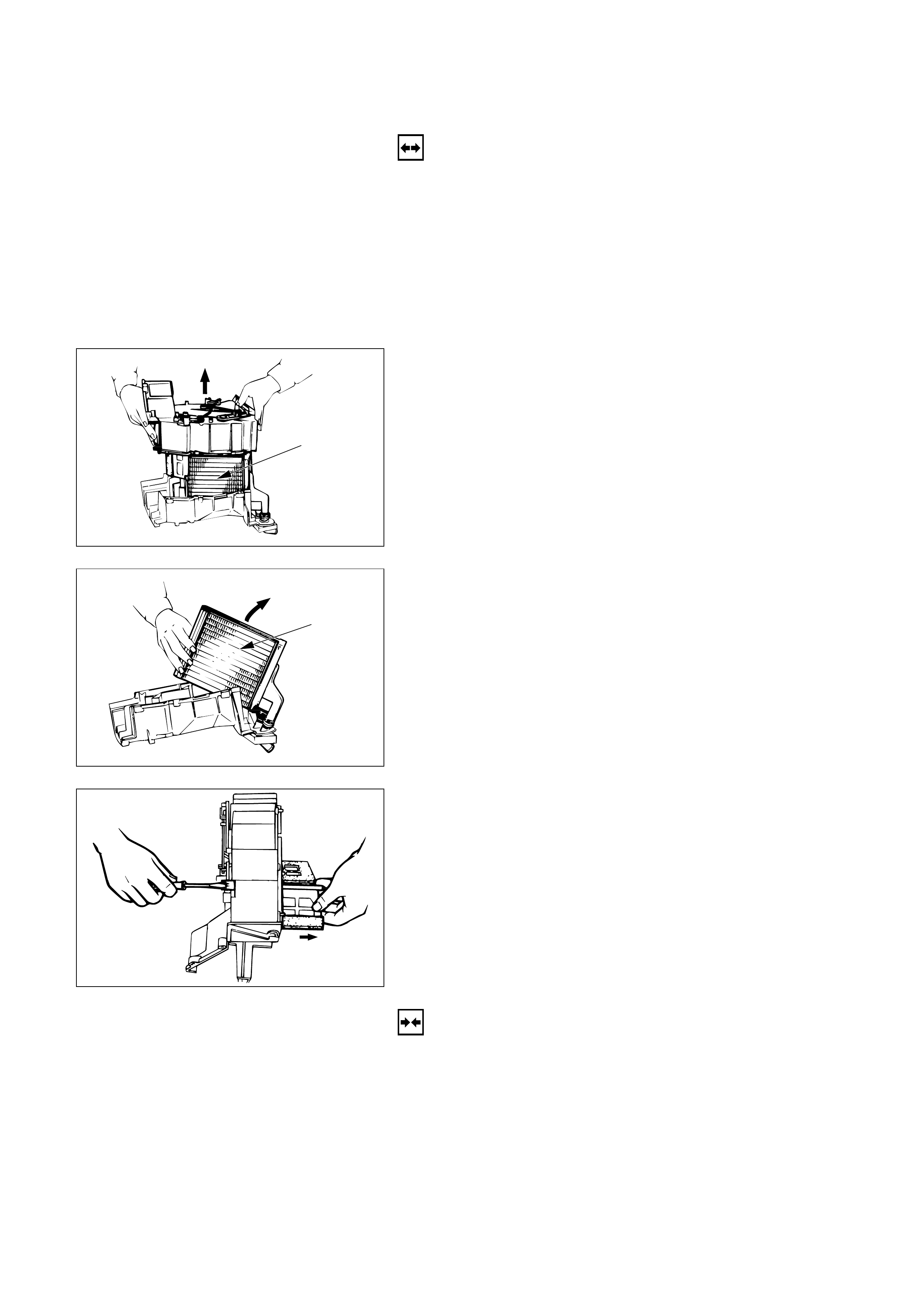
HEATER CORE AND/OR MODE DOOR
4
5
3
2
16
This illustration is based on LHD
REMOVAL
Preparation:
• Disconnect the battery ground cable
• Drain engine coolant
1. Heater Unit
Refer to “HEATER UNIT” removal procedure in this
section.
2. Duct
3. Case (Mode Control)
Do not remove link unit at this step.
4. Case (Temperature Control)
Separate two halves of core case.
Heater core
5. Heater Core
Heater core
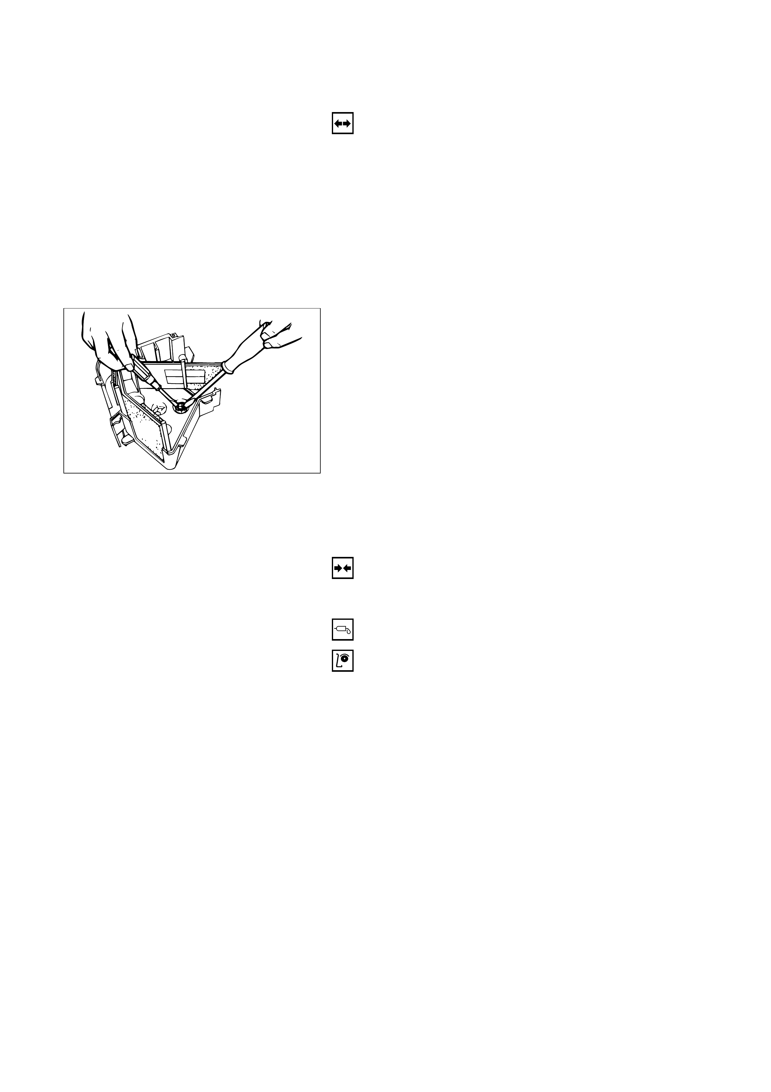
6. Mode Door
Pull out the mode door while raising up the catch of
the door lever.
INSTALLATION
To install, follow the removal steps in the reverse order,
noting the following point:
1. Check that each mode door operates properly.
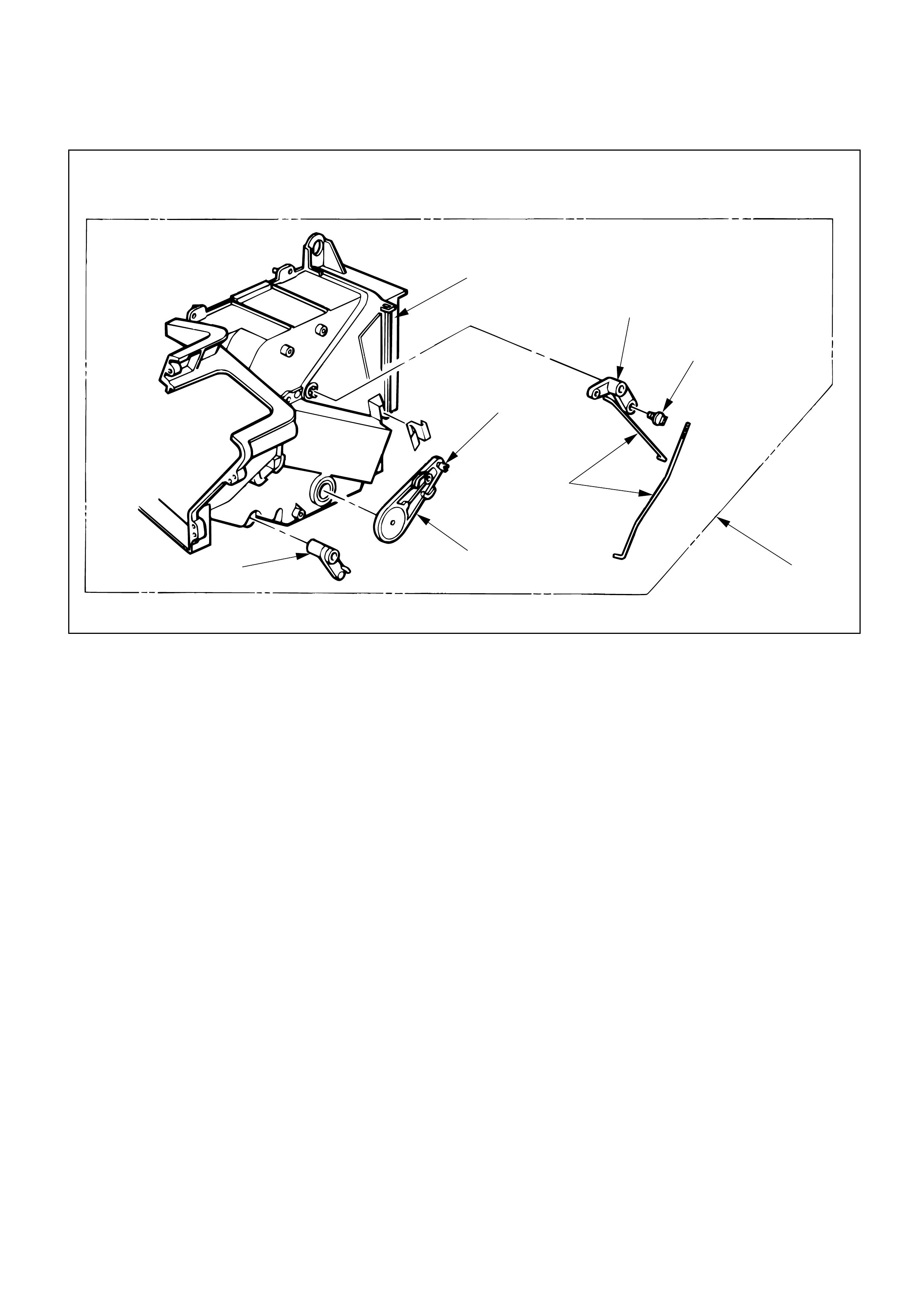
Removal Steps
1. Heater unit
2. Case (Mode control)
3. Washer and mode main lever
4. Rod
5. Mode sub-lever
6. Door lever
7. Clip
Installation Steps
To install, follow the removal steps in the
reverse order.
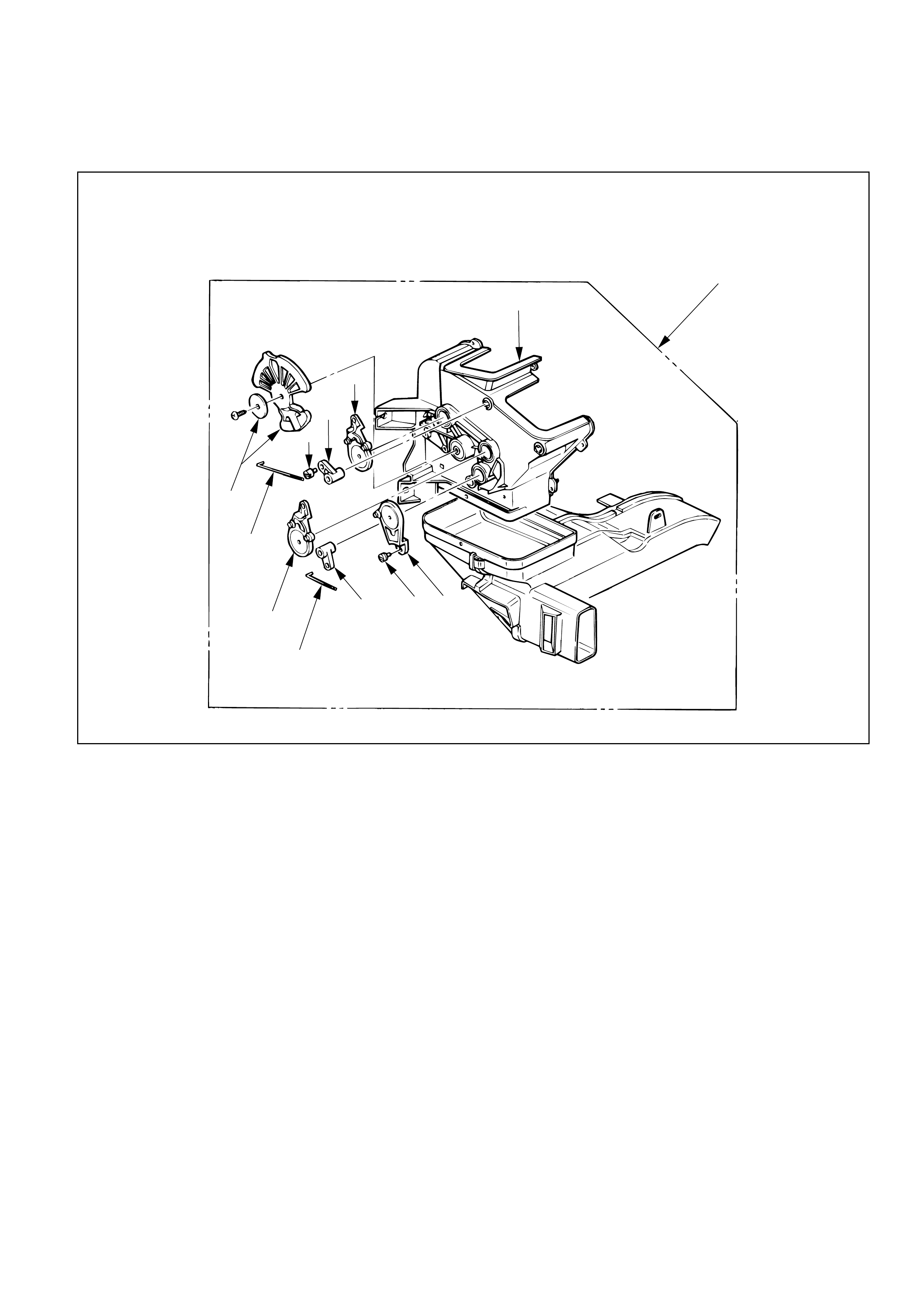
HEATER MODE CONTROL LINK UNIT
This illustration is based on LHD
1
2
5
6
7
3
4
5
4
675
REMOVAL
Preparation:
• Disconnect the battery ground cable
• Drain engine coolant
1. Heater Unit
Refer to “HEATER UNIT” removal procedure in this
section.
2. Case (Mode Control)
Remove the case (Mode control) from heater unit.
3. Washer and Mode Main Lever
4. Rod
5. Mode Sub-Lever
Press the tab of the sub-lever inward, and take out the
sub-lever.
6. Door Lever
Pull out the door lever while raising up the catch of
the door lever.
INSTALLATION
To install, follow the removal steps in the reverse order,
noting the following points:
1. Apply grease to mode sub-lever and to the abrasive
surface of the heater unit.
2. After installing the link unit, check to see if the link
unit operates correctly.
Removal Steps
1. Heater unit
2. Case (Temperature control)
3. Rod
4. Sub-lever
5. Door lever
6. Clip
Installation Steps
To install, follow the removal steps in the
reverse order.
HEATER TEMPERATURE CONTROL LINK UNIT
2
5
6
6
4
51
3
This illustration is based on LHD

REMOVAL
Preparation:
• Disconnect the battery ground cable
• Drain engine coolant
1. Heater Unit
Refer to “HEATER UNIT” removal procedure in this
section.
2. Case (Temperature Control)
Remove the case (Temperature control) from the
heater unit.
3. Rod
4. Sub-Lever
5. Door Lever
Pull out the door lever while raising up the catch of
the door lever.
6. Clip
INSTALLATION
To install, follow the removal steps in the reverse order,
noting the following points:
1. Apply grease to sub-lever and to the abrasive surface
of the heater unit.
2. After installing the link unit, check to see if the link
unit operates correctly.
Removal Steps
1. Instrument panel assembly
2. Resistor connector
3. Duct
3a. Evaporator assembly (A/C only)
4. Kick panel
5. Blower motor connector
6. Blower assembly
Installation Steps
To install, follow the removal steps in the
reverse order.
BLOWER ASSEMBLY
2
3a(With A/C)
3
Heater unit
Electro thermo connector
(With A/C)
14
6
5
This illustration is based on LHD

REMOVAL
Preparation:
• Disconnect the battery ground cable
• Discharge and recover refrigerant (W/A/C)
(Refer to Section 2B “REFRIGERANT RECOVERY”)
1. Instrument Panel Assembly
Refer to Section 1 “BODY” for INSTRUMENT PANEL
ASSEMBLY removal procedure.
2. Resistor Connector
3. Duct
3a. Evaporator Assembly (A/C only)
Refer to Section 2B “AIR CONDITIONING” for
EVAPORATOR ASSEMBLY removal procedure.
4. Kick panel
5. Blower Motor Connector
6. Blower Assembly
INSTALLATION
To install, follow the removal steps in the reverse order,
noting the following point:
1. Adjust Control Lever Assembly Cables
Refer to “CONTROL LEVER ASSEMBLY” installation
procedure in this section.
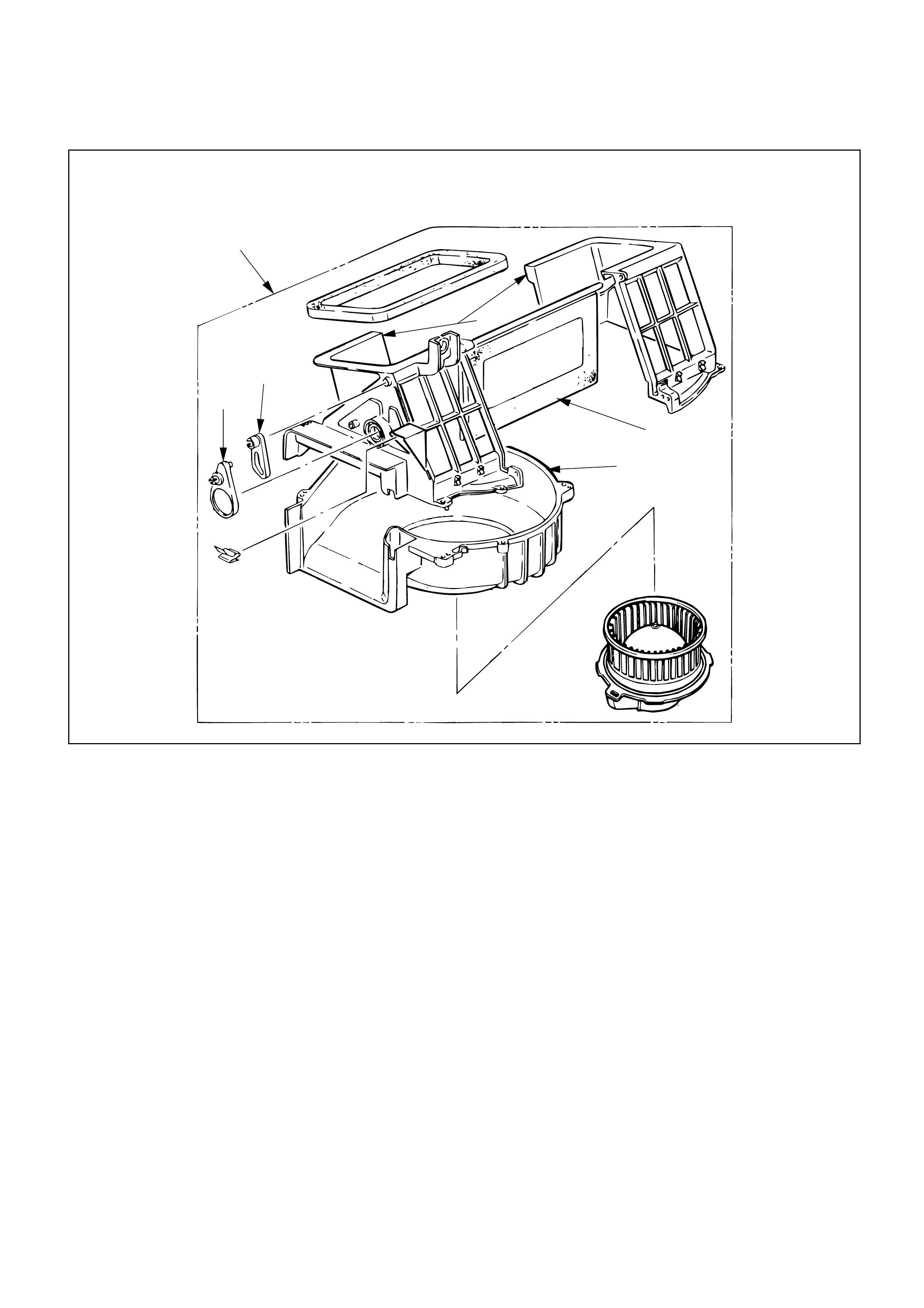
Removal Steps
1. Blower assembly
2. Lower case
3. Upper case
4. Mode door
5. Sub-lever
6. Door lever
Installation Steps
To install, follow the removal steps in the
reverse order.
BLOWER LINK UNIT AND/OR MODE DOOR
This illustration is based on LHD
1
3
6
2
4
5
REMOVAL
Preparation:
Disconnect the battery ground cable
1. Blower Assembly
Refer to “BLOWER ASSEMBLY” removal procedure
in this section.
2. Lower Case
3. Upper Case
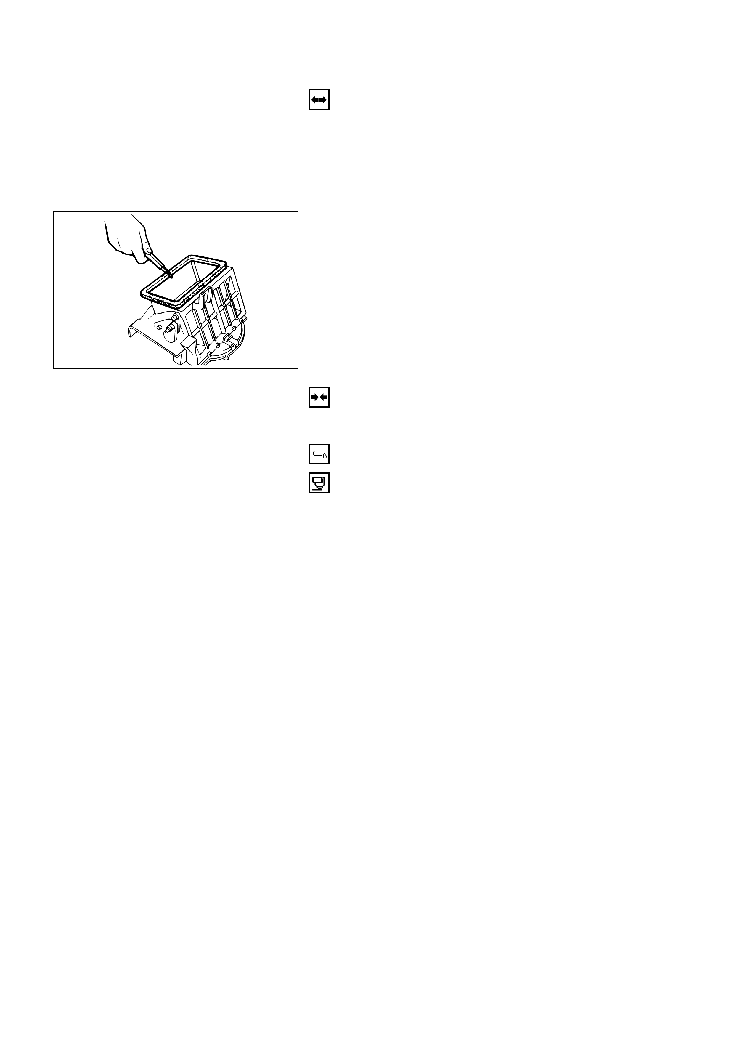
Separate upper case and slit the lining parting face
with a knife.
INSTALLATION
To install, follow the removal steps in the reverse order,
noting the following points:
1. Apply grease to the door lever and to the abrasive
surface of the upper case.
2. Apply an adhesive to parting face of lining when
assembling upper case.
3
4
2
1
5
6
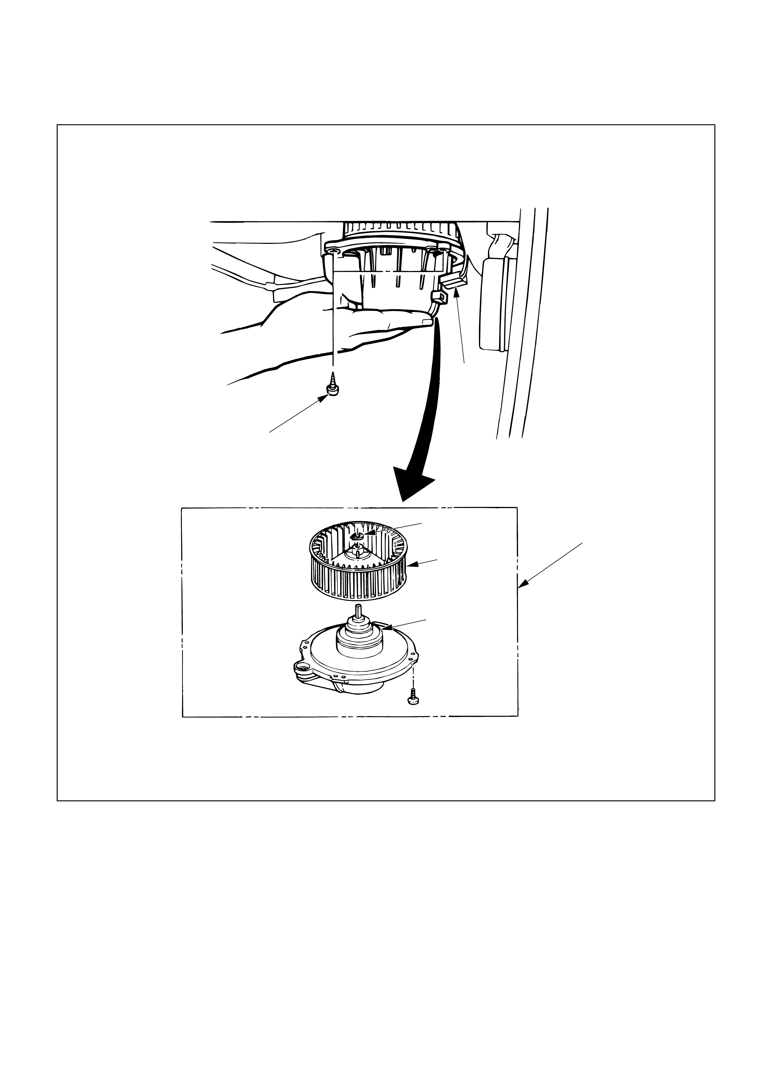
Removal Steps
1. Blower motor connector
2. Attaching screw
3. Blower motor assembly
4. Clip
5. Fan
6. Blower motor
Installation Steps
To install, follow the removal steps in the
reverse order.
BLOWER MOTOR
This illustration is based on LHD

REMOVAL
Preparation:
Disconnect the battery ground cable
1. Blower Motor Connector
2. Attaching Screw
3. Blower Motor Assembly
4. Clip
5. Fan
6. Blower Motor
INSTALLATION
To install, follow the removal steps in the reverse order.
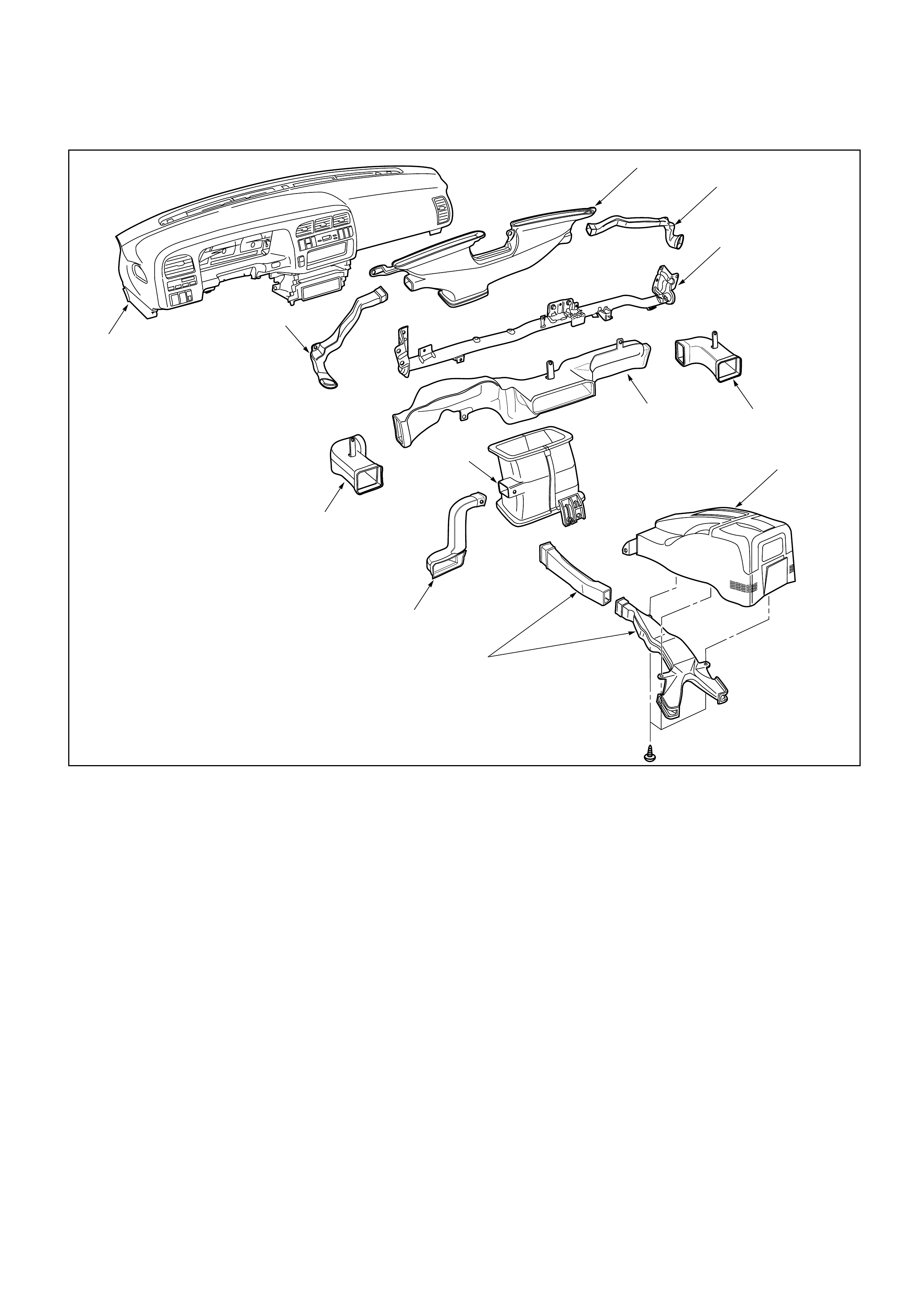
REAR HEATER DUCT, DEFROSTER NOZZLE AND VENTILATION DUCT
Removal Steps
1. Instrument panel assembly
2. Center ventilation upper duct
3. Side ventilation duct
4. Center ventilation lower duct
5. Driver lap duct
6. Center console
7. Rear heater duct
8. Cross beam assembly
9. Side defroster nozzle
10. Center defroster nozzle
Installation Steps
To install, follow the removal steps in the
reverse order.
7
9
9
10
8
6
3
5
1
3
4
2
This illustration is based on LHD

INSTALLATION
To install, follow the removal steps in the reverse order,
noting the following point:
1. Connect each duct and nozzle securely leaving no
clearance between them and making no improper
matching.
REMOVAL
Preparation:
Disconnect the battery ground cable
1. Instrument panel assembly
• Refer to Section 1 “BODY” for INSTRUMENT
PANEL ASSEMBLY removal procedure.
2. Center ventilation upper duct
3. Side ventilation duct
4. Center ventilation lower duct
5. Driver lap duct
6. Center console
7. Rear heater duct
• Refer to Section 1 “BODY” for CONSOLES
removal procedure.
8. Cross beam assembly
• Refer to Section 1 “BODY” for CROSS BEAM
ASSEMBLY removal procedure.
9. Side defroster nozzle
10. Center defroster nozzle
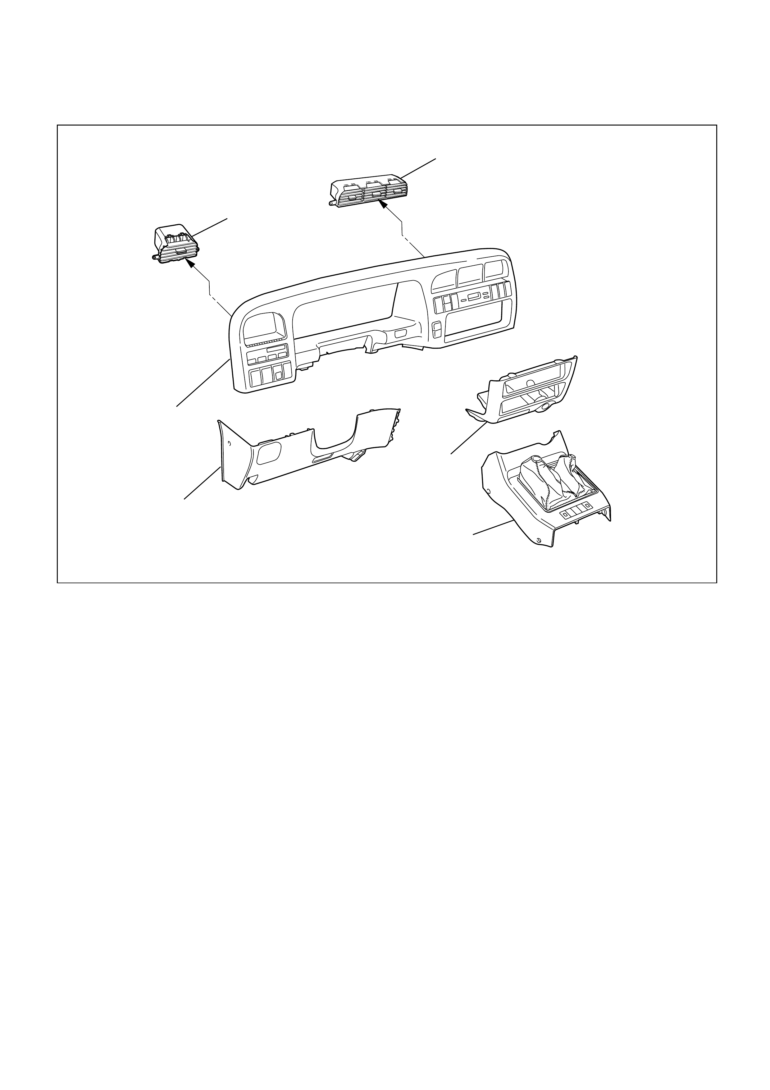
Removal Steps
1. Front console assembly
2. Lower cluster assembly
3. Instrument panel driver lower
cover assembly
4. Meter cluster assembly
5. Center vent
6. Side vent
Installation Steps
To install, follow the removal steps in the
reverse order.
CENTER AND/OR SIDE VENT
6
5
3
1
2
4
This illustration is based on LHD
740RW168

INSTALLATION
To install, follow the removal steps in the reverse order.
REMOVAL
1. Front console assembly
2. Lower cluster assembly
3. Instrument panel driver lower cover assembly
4. Meter cluster assembly
• Refer to Section 1 “BODY” for INSTRUMENT
PANEL ASSEMBLY removal procedure.
5. Center vent
•Remove screws and the center vent from center
cluster while prying up the center vent catch
portions.
6. Side vent
•Remove screws and the side vent from center
cluster while prying up the side vent catch
portions.
Removal Steps
1. Center console assembly
2. Lower cluster assembly
3. Glove box
4. Instrument panel passenger lower
cover assembly
5. Instrument panel driver lower cover
assembly
6. Meter cluster assembly
7. Attaching screws
8. Fan switch and air conditioning switch
connector
9. Control lever assembly
10. Control cable
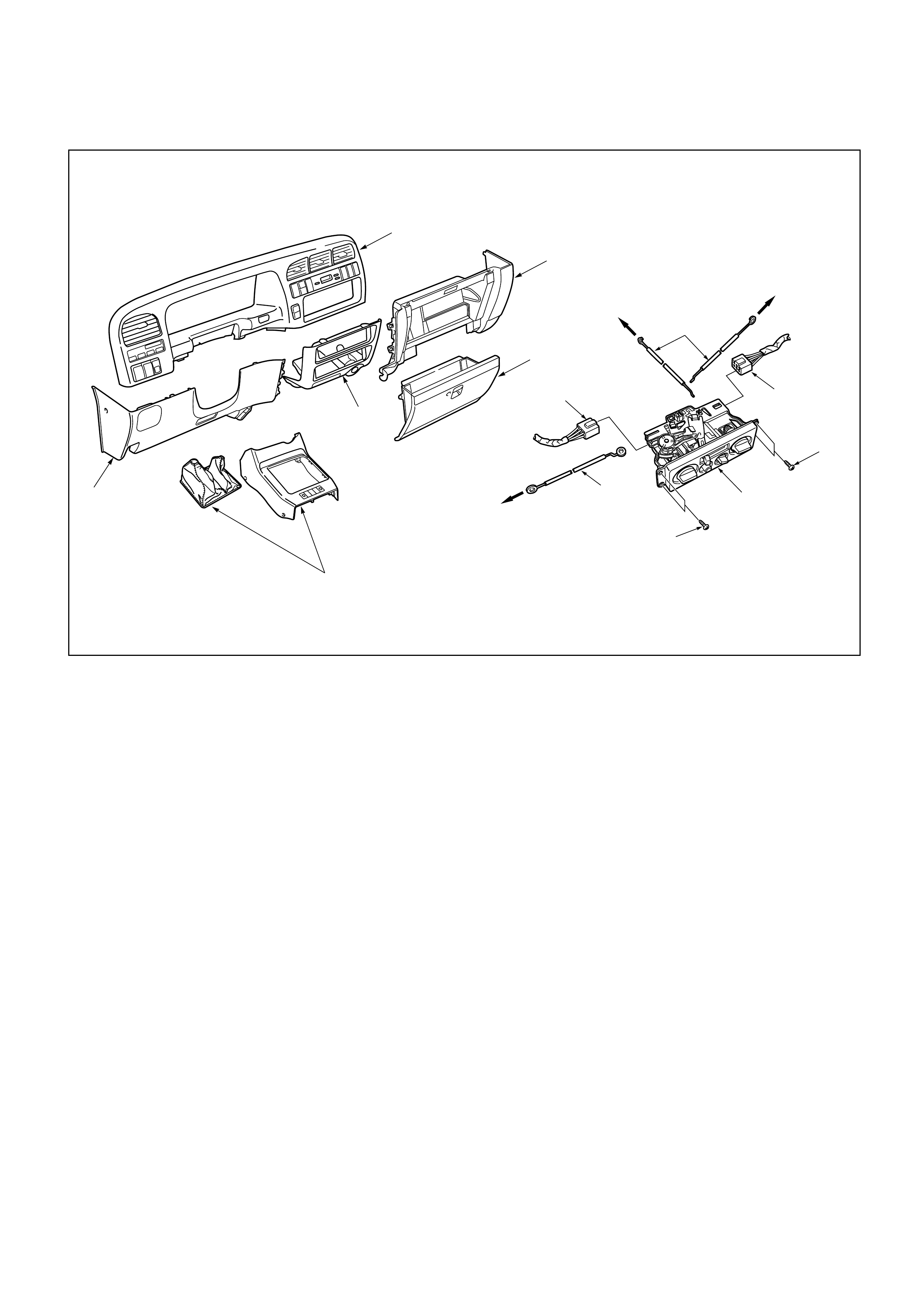
CONTROL LEVER ASSEMBLY AND/OR CONTROL CABLES
6
1
5
2
10
7
7
8
8
9
10
To Mode control link
To Temp control link To Blower assembly
4
3
Installation Steps
To install, follow the removal steps in
the reverse order.
This illustration is based on LHD
REMOVAL
Preparation:
Disconnect the battery ground cable
1. Front console assembly
2. Lower cluster assembly
3. Glove box
4. Instrument panel passenger lower cover
5. Instrument panel driver lower cover
6. Meter cluster assembly
Refer to Section 1 “BODY” for INSTRUMENT PANEL
ASSEMBLY removal procedure.
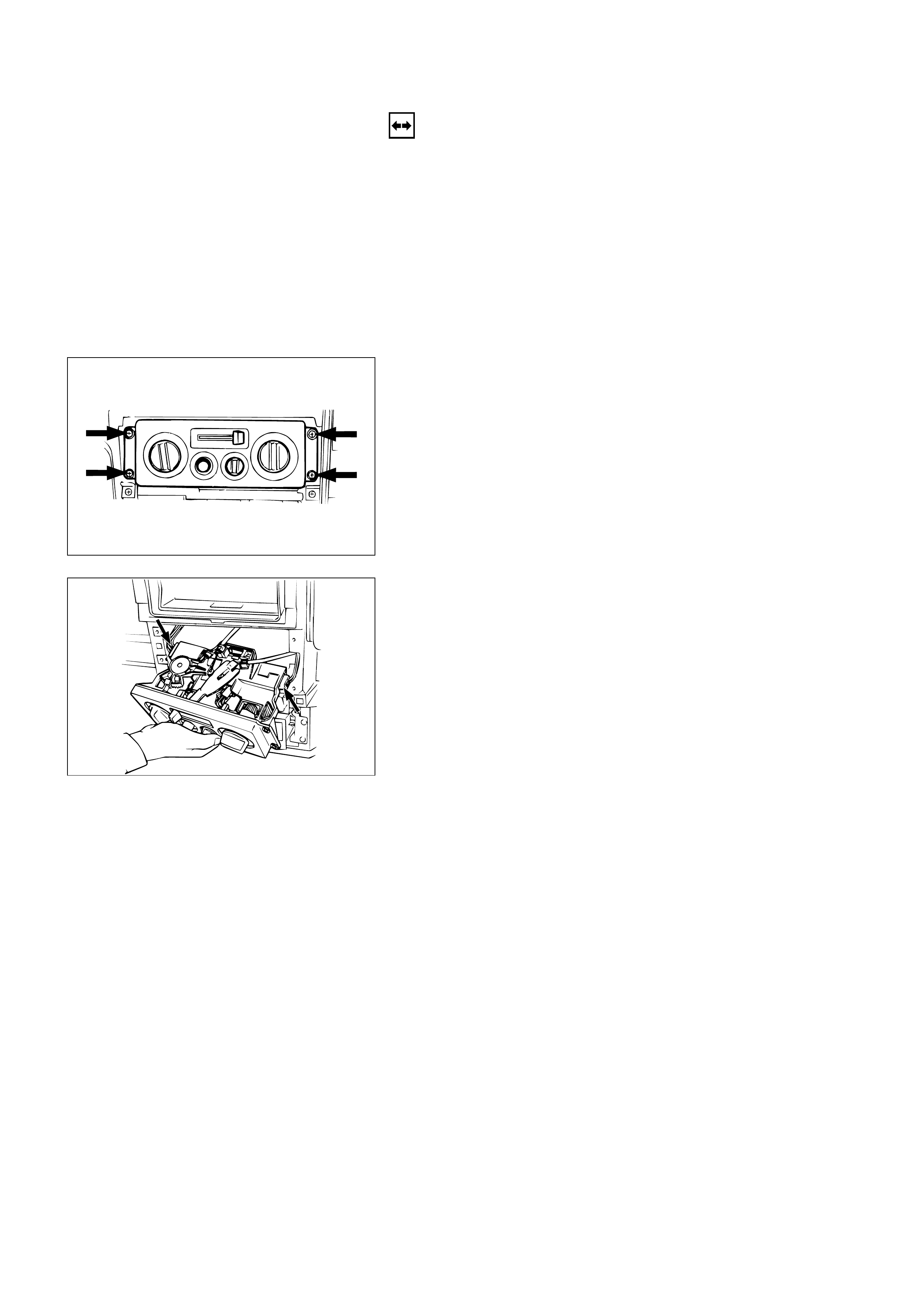
7. Attaching Screws
Remove the 4 attaching screws and disconnect the
control lever cables at heater unit and blower
assembly.
8. Fan Switch and A/C Switch Connector
Pull the control lever assembly out and disconnect
the connectors.
9. Control Lever Assembly
10. Control Cable
INSTALLATION
To install, follow the removal steps in the reverse order,
noting the following points:
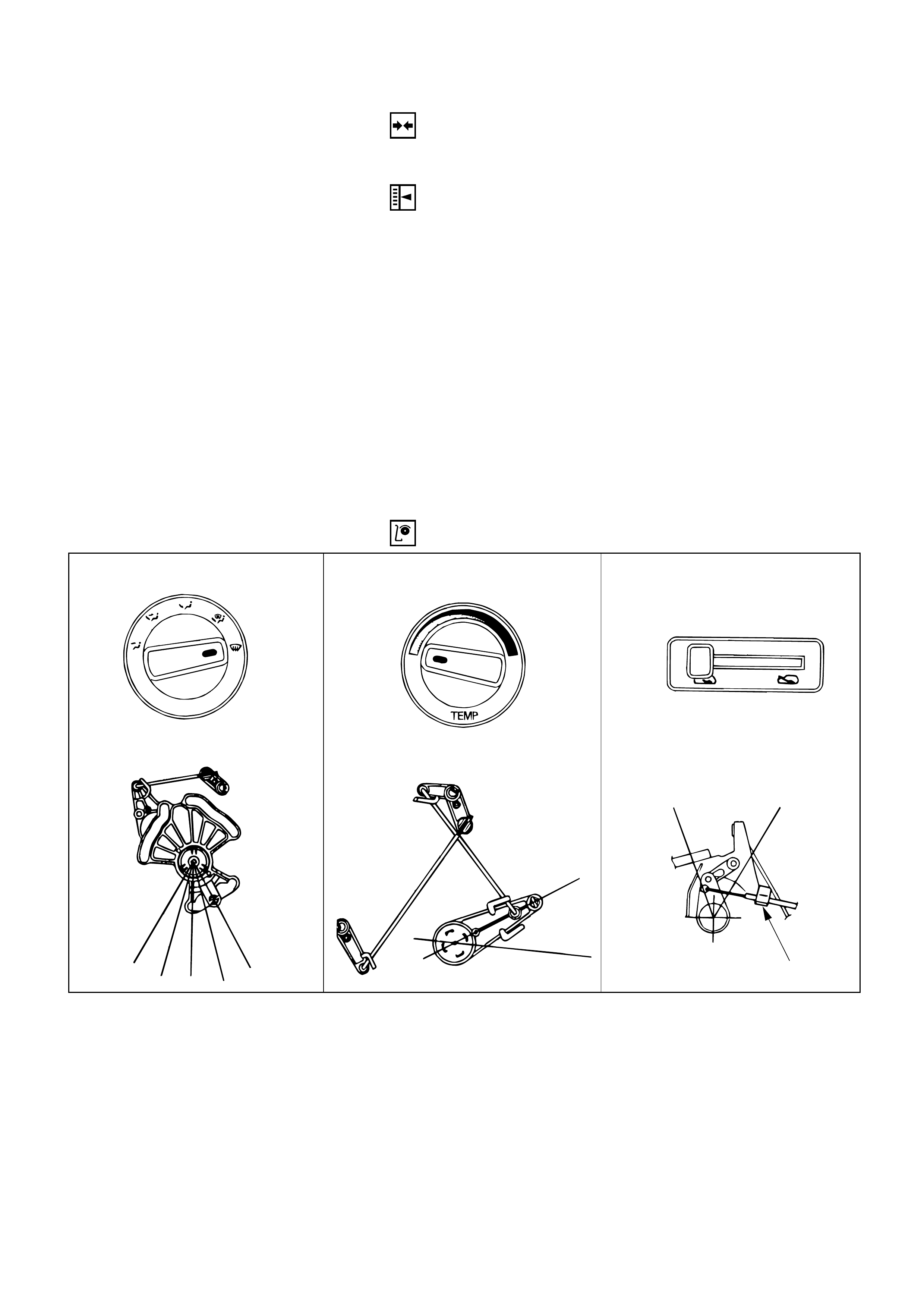
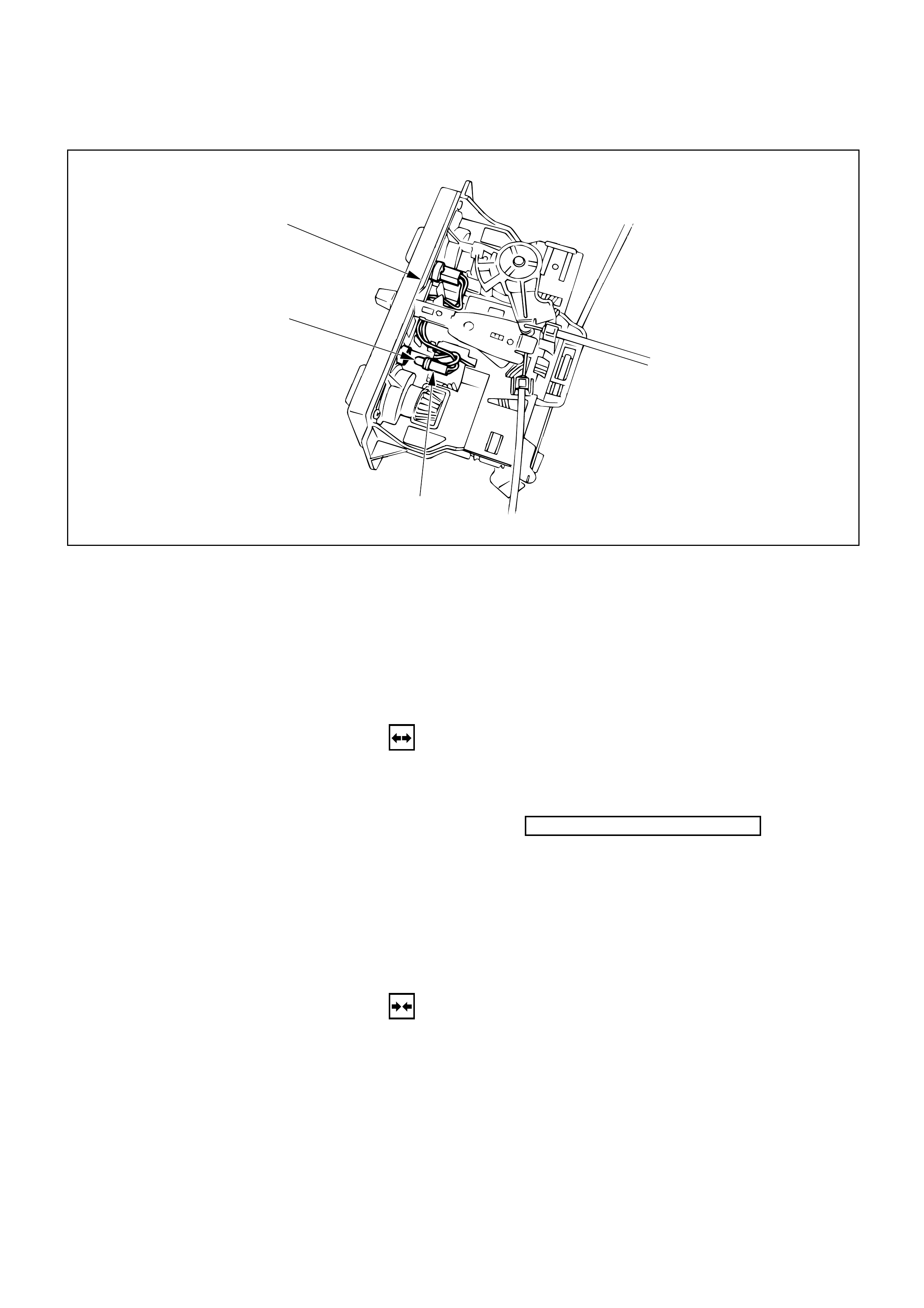
1. Adjust the control cables
Air source control cable
1) Slide the control lever to the left (“CIRC” position).
2) Connect the control cable at the “CIRC” position of
the link unit of blower assembly and fix it with the
clip.
Temperature control cable
1) Turn the control knob to the left (“MAX COLD”
position).
2) Connect the control cable at the “COLD” position
of the temperature control link of the heater unit
and fix it with the clip.
Air select control cable
1) Turn the control knob to the right (“DEFROST”
position).
2) Connect the control cable at the “DEFROST”
position of the mode control link of the heater unit
and fix it with the clip.
2. Check control cable operation.
AIR SELECTOR CABLE
Air selector knob
VENT
BI-LEVEL
FOOT
DEF/FOOT
DEF
(DEF)
TEMPERATURE CONTROL CABLE
Temperature control knob
COLD
HOT
(MAX
COLD)
AIR SOURCE SELECT CABLE
Air source select lever
(CIRC)
CIRC FRESH
Clip
Removal Steps
1. Control lever assembly
2. Bulb socket
3. Illumination bulb
Installation Steps
To install, follow the removal steps in the
reverse order.
CONTROL PANEL ILLUMINATION BULB
2
3
1
REMOVAL
Preparation:
Disconnect the battery ground cable
1. Control Lever AssemblyRefer to “CONTROL LEVER ASSEMBLY” removal
procedure in this section.
2. Bulb Socket
Pull out the socket from the panel by turning it
counterclockwise.
3. Illumination Bulb
Pull the illumination bulb from socket.
INSTALLATION
To install, follow the removal steps in the reverse order.
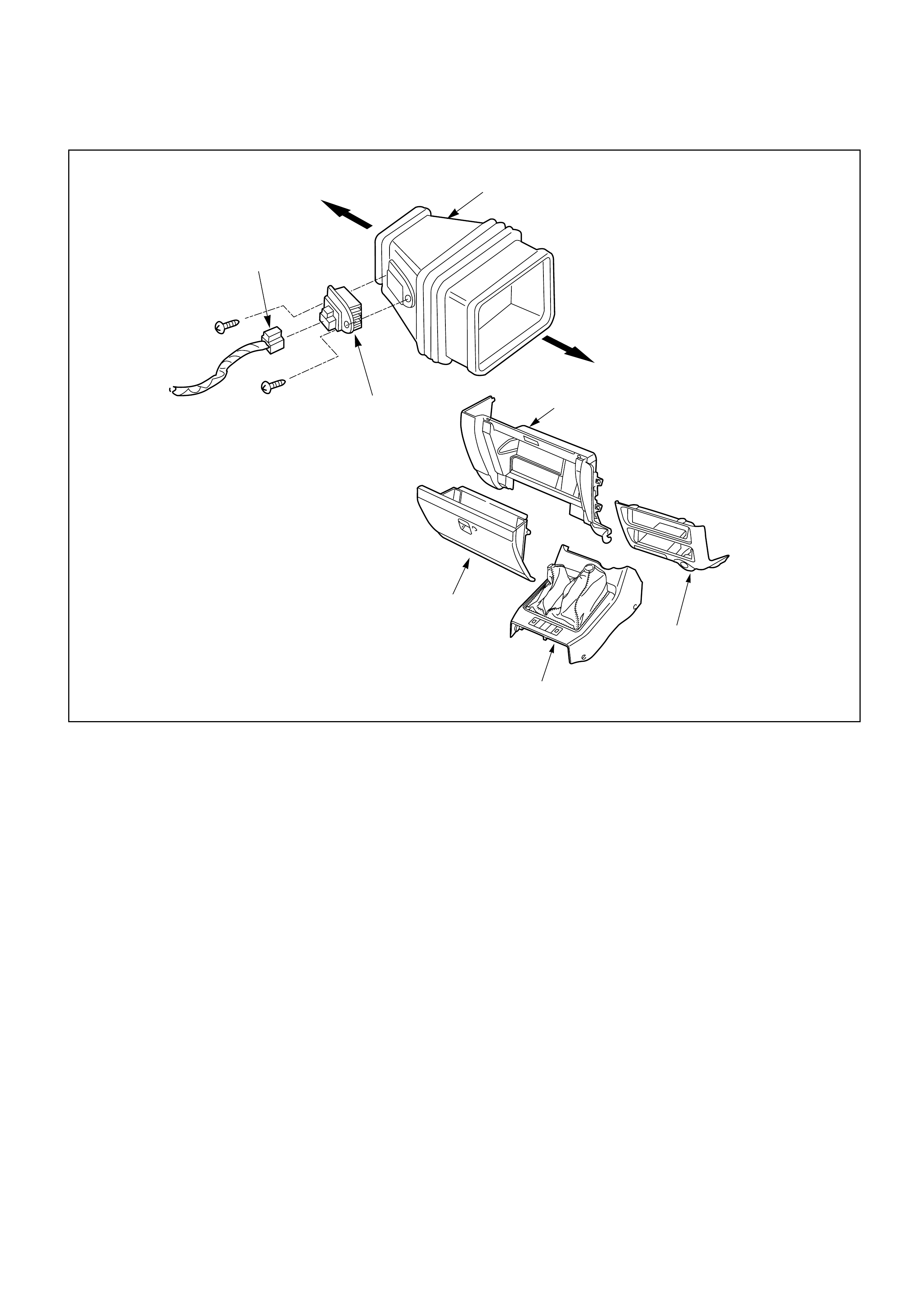
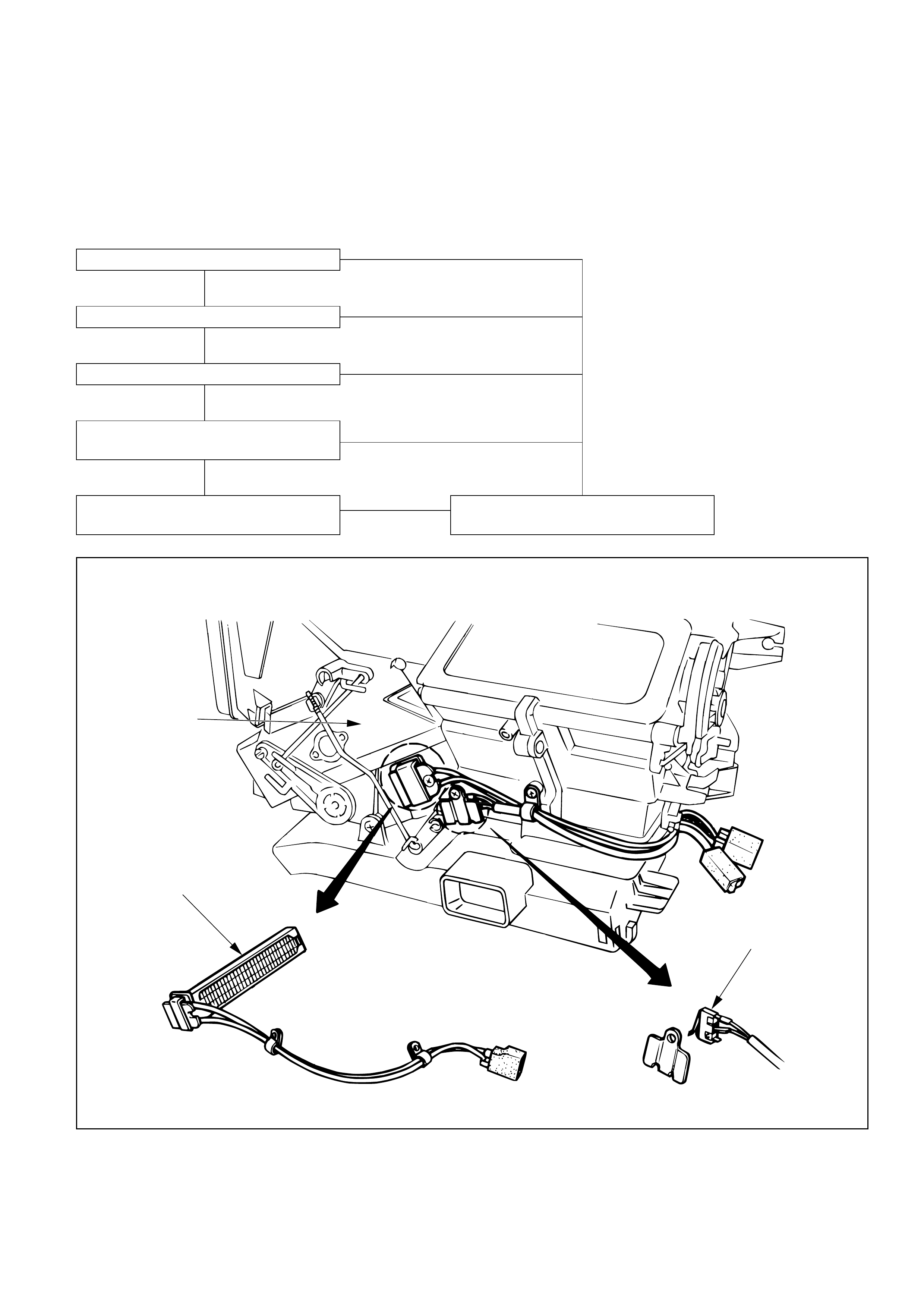
5
7
6
To Blower unit
To Heater unit
3
4
1
2
Removal Steps
1. Front console assembly
2. Lower cluster assembly
3. Glove box
4. Instrument panel passenger
lower cover
5. Resistor connector
6. Duct (Heater only)
7. Resistor
Installation Steps
To install, follow the removal steps in the
reverse order.
RESISTOR
This illustration is based on RHD

REMOVAL
Preparation:
Disconnect the battery ground cable
1. Front console assembly
2. Lower cluster assembly
3. Glove box
4. Instrument panel passenger lower cover
Refer to “BODY” for INSTRUMENT PANEL
ASSEMBLY removal procedure.
5. Resistor connector
6. Duct (Heater only)
7. Resistor
INSTALLATION
To install, follow the removal steps in the reverse order.