
CAUTION
When fasteners are removed, always
reinstall them at the same location from
which they were removed. If a fastener
needs to be replaced, use the correct part
number fastener for that application. If the
correct part number fastener is not available,
a fastener of equal size and strength (or
stronger) may be used.
Fasteners that are not reused, and those
requiring thread locking compound, will be
called out. The correct torque values must
be used when installing fasteners that
require it. If the above conditions are not
followed, parts or system damage could
result.
SECTION 2B - HVAC AIR CONDITIONING
General Description
Air Conditioning Refrigerant Cycle Construction
Compressor
Magnetic Clutch
Receiver/Drier
Dual Pressure Switch
Triple Pressure Switch
Expansion Valve
Evaporator
Electronic Thermostat
Refrigerant Line
Service Charge Valve
Air Conditioning Parts
On-Vehicle Service
Precautions For Replacement or Repair of Air Conditioning Parts
Compressor Assembly and Associated Parts
Condenser Assembly (Shown without Condenser Fan)
Condenser Fan Motor
Receiver/Drier
Pressure Switch
Evaporator Assembly
Evaporator Core and/or Expansion Valve
Electronic Thermostat
A/C Switch and Illumination Bulb
Refrigerant Line
Rear Cooler Parts
Techline
Techline

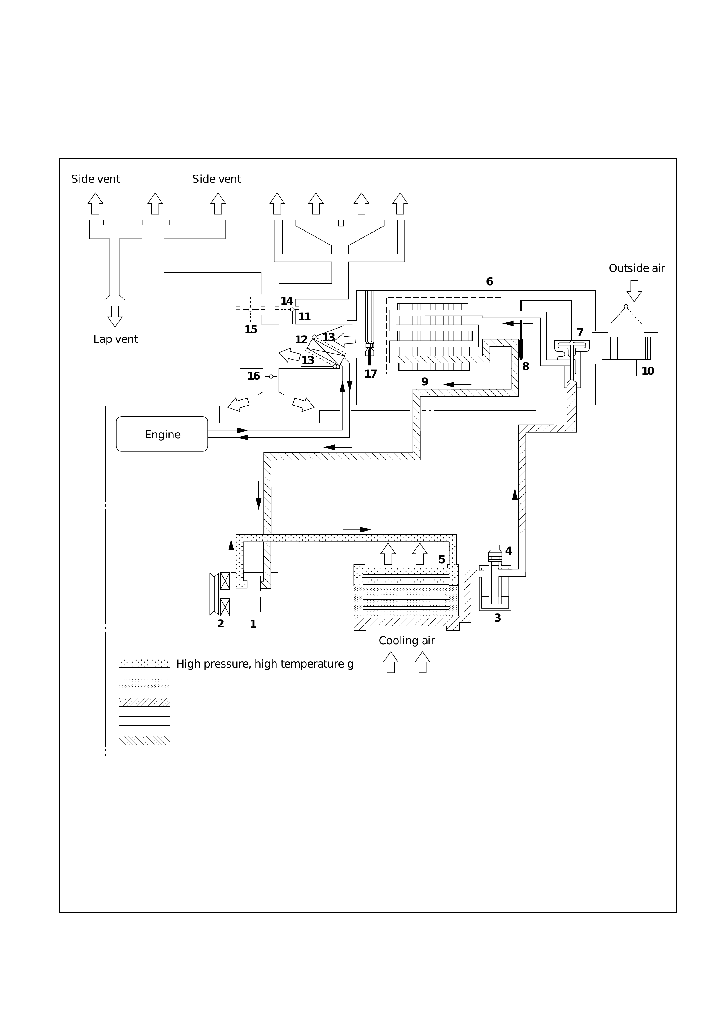
AIR CONDITIONING REFRIGERANT CYCLE CONSTRUCTION
;;
;;
;;
;;;;
;;;;
;;;
;
;;
;;
;;
;;;
;;;
;;;
;;;
;;;;;;;;;
;;;;;;;;;
;;;;;;;;;
;;;;;;;;
;
;;;;;;
;
;;;;;;;;
;;
;
;;;
;
;;;
;;;
;;;;;
;;;;;
;;
;
;
;;
15
14 11
12
13
16
10
17
7
3
4
5
2
1
8
9
6
13
Side vent
Lap vent
Outside air
Engine
Side vent
Cooling air
High pressure, high temperature gas
High pressure, high temperature
mixture of gas and liquid
Low pressure, low temperature
mixture of liquid and gas
Low pressure, low temperature gas
High pressure, medium temperature liquid
Side defrost Side defrostDefrostCenter vent
GENERAL DESCRIPTION
1. Compressor
2. Magnetic clutch
3. Receiver/Drier
4. Dual pressure switch
5. Condenser
6. Evaporator assembly
7. Expansion valve
8. Temperature sensor
9. Evaporator core
10. Blower motor
11. Heater unit
12. Heater core
13. Temp. control door (Air mix door)
14. Mode (DEF) control door
15. Mode (VENT) control door
16. Mode (HEAT) control door
17. Electronic thermostat

The refrigeration cycle includes the following four
processes as the refrigerant changes repeatedly
from liquid to gas and back to liquid while
circulating.
EVAPORATION
The refrigerant is changed from a liquid to a gas
inside the evaporator. The refrigerant mist that
enters the evaporator vaporizes readily. The liquid
refrigerant removes the required quantity of heat
(latent heat of vaporization) from the air around the
evaporator core cooling fins and rapidly vaporizes.
Removing the heat cools the air, which is then
radiated from the fins and lowers the temperature
of the air inside the vehicle.
The refrigerant liquid sent from the expansion valve
and the vaporized refrigerant gas are both present
inside the evaporator and the liquid is converted to
gas.
With this change from liquid to gas, the pressure
inside the evaporator must be kept low enough for
vaporization to occur at a lower temperature.
Because of that, the vaporized refrigerant is sucked
into the compressor.
COMPRESSION
The refrigerant is compressed by the compressor
until it is easily liquefied at normal temperature.
The vaporized refrigerant in the evaporator is
sucked into the compressor. This action maintains
the refrigerant inside the evaporator at a low
pressure so that it can easily vaporize, even at low
temperatures close to freezing point.
Also, the refrigerant sucked into the compressor is
compressed inside the cylinder to increase the
pressure and temperature to values such that the
refrigerant can easily liquefy at normal ambient
temperatures.
CONDENSATION
The refrigerant inside the condenser is cooled by
the outside air and changes from gas to liquid.
The high temperature, high pressure gas coming
from the compressor is cooled and liquefied by the
condenser with outside air and accumulated in the
receiver/drier. The heat radiated to the outside air
by the high temperature, high pressure gas in the
compressor is called heat of condensation. This is
the total quantity of heat (heat of vaporization) the
refrigerant removes from the vehicle interior via the
evaporator and the work (calculated as the quantity
of heat) performed for compression.
EXPANSION
The expansion valve lowers the pressure of the
refrigerant liquid so that it can easily vaporize.
The process of lowering the pressure to encourage
vaporization before the liquefied refrigerant is sent
to the evaporator is called expansion. In addition,
the expansion valve controls the flow rate of the
refrigerant liquid while decreasing the pressure.
That is, the quantity of refrigerant liquid vaporized
inside the evaporator is determined by the quantity
of heat which must be removed at a prescribed
vaporization temperature. It is important that the
quantity of refrigerant be controlled to exactly the
right value.
COMPRESSOR
The compressor performs two main functions:
It compresses low-pressure and low-temperature
refrigerant vapor from the evaporator into high-
pressure and high-temperature refrigerant vapor to
the condenser. And it pumps refrigerant and
refrigerant oil through the A/C system.
The compressor sucks and compresses refrigerant
by the rotation of the vane installed to the shaft,
and always discharges a fixed amount of refrigerant
independent of the load of refrigerant.
The thermo sensor is installed to the front head of
the compressor to protect it by stopping its
operation when the refrigerant gas is insufficient or
when the temperature is abnormally high.
OFF ........ 160o C
ON .......... 135oC
Swash plate compressors have a swash (slanted)
plate mounted on the shaft. W hen the shaft turns,
the rotation of the swash plate is converted to
reciprocating piston motion which sucks in and
compresses the refrigerant gas.
Shaft seal (Lip type) is installed between the valve
plate and shaft & cylinder head to prevent
refrigerant gas leaks. A specified amount of
compressor oil is contained in the oil pan.
This oil is supplied to the cylinders, bearings, etc.,
by an oil pump which is connected to the swash
plate shaft.
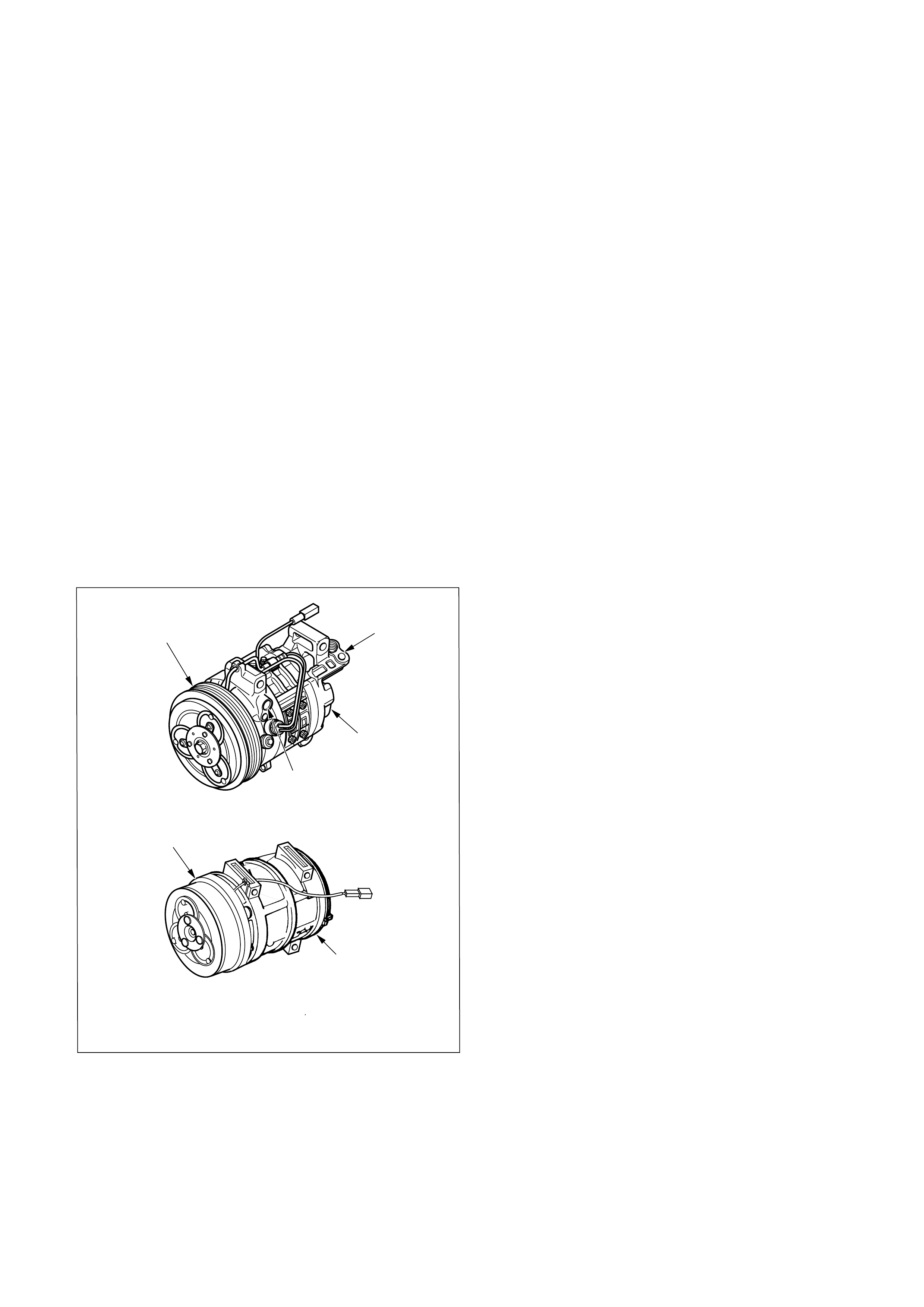
COMPRESSOR TYPES
6VE1(MY1998-2001) Zexel DKV-14D Rotary
6VE1 (MY2002) Zexel DKV-14G Rotary
4JX1 (MY1998-2002) Zexel DKS -15CH Swash Plate
With some compressors the differential between
the intake pressure and discharge pressure
generated while the compressor is operating is
used for lubrication instead of an oil pump.
The specified amount of the DKV-14D, DKS-15CH
and HD6 compressors oil is 150cc (4.2 Imp fl oz).
Also, compressor oil to be used varies according to
the compressor model. Be sure to avoid mixing
two or more different types of oil.
If the wrong oil is used, lubrication will be poor and
the compressor will seize or malfunction.
The magnetic clutch connector is a waterproof type.
MAGNETIC CLUTCH
The compressor is driven by the drive belt from the
crank pulley of the engine. If the compressor is
activated each time the engine is started, this
causes too much load to the engine. The magnetic
clutch transmits the power from the engine to the
compressor and activates it when the air
conditioning is “ON”. Also, it cuts off the power
from the engine to the compressor when the air
conditioning is “OFF”. (Magnetic clutch repair
procedure can be found in Section 2E.)
CONDENSER
The condenser assembly in front of the radiator,
which carry the refrigerant and cooling fins to
provide rapid transfer of heat.
Also, it functions to cool and liquefy the high-
pressure and high-temperature vapor sent from the
compressor by the radiator fan or outside air.
A condenser may malfunction in two ways: it may
leak, or it may be restricted. A condenser restriction
will result in excessive compressor discharge
pressure. If a partial restriction is present, the
refrigerant expands after passing through the
restriction.
Thus, ice or frost may from immediately after the
restriction. If air flow through the condenser or
radiator is blocked, high discharge pressures will
result. During normal condenser operation, the
refrigerant outlet line will be slightly cooler than the
inlet line.
The vehicle is equipped with the condenser of the
parallel flow type condenser. A larger thermal
transmission area on the inner surface of the tube
allows the radiant heat to increase and the
ventilation resistance to decrease.
The refrigerant line connection has a bolt at the
block joint, for easy servicing.
RECEIVER/DRIER
The receiver/drier performs four functions;
•As the quantity of refrigerant circulated varies
depending on the refrigeration cycle conditions,
sufficient refrigerant is stored for the refrigera-
tion cycle to operate smoothly in accordance
with fluctuations in the quantity circulated.
•The liquefied refrigerant from the condenser is
mixed with refrigerant gas containing air
bubbles. If refrigerant containing air bubbles is
sent to the expansion valve, the cooling
capacity will decrease considerably. Therefore,
the liquid and air bubbles are separated and
only the liquid is sent to the expansion valve.
•The receiver/drier utilizes a filter and dryer to
remove the dirt and water mixed in the cycling
refrigerant.
•The sight glass, installed atop the receiver/
drier, show the state of the refrigerant.
A receiver/drier may fail due to a restriction inside
the body of the unit. A restriction at the inlet to the
receiver/drier will cause high pressures.
Outlet restrictions will be indicated by low pressure
and little or no cooling. An excessively cold
receiver/ drier outlet may indicate a restriction.
The receiver/drier of this vehicle is made of
aluminum with a smaller tank. It has 300 cc
(8.5 Imp fl oz) refrigerant capacity.
The refrigerant line connection has a bolt at the
block joint, for easy servicing.
DKV-14D TYPE
DKS-15CH TYPE
Magnetic clutch
Compressor
Suction side
Discharge side
Compressor
Magnetic clutch
871RY00012
871RY00011
DUAL PRESSURE SWITCH
The dual pressure switch is installed on the upper
part of the receiver/drier, to detect excessively high
pressure (high pressure switch) and prevent
compressor seizure due to the refrigerant leaking
(low pressure switch), switching the compressor
“ON” or “OFF” as required.
The pressure switch connector is waterproof type.
•Low-pressure control kpa (kg·cm2/ PSI)
Compressor
ON: 205.9 ± 30 (2.1 ± 0.3 / 30 ± 4)
OFF: 176 ± 20 (1.8 ± 0.2 / 26 ± 3)
•High-pressure control
Compressor
ON: 2354 ± 196 (24.0 ± 2.0 / 341 ± 28)
OFF: 2942 ± 196 (30.0 ± 2.0 / 427 ± 28)
TRIPLE PRESSURE SWITCH
Triple pressure switch is installed atop the receiver/
drier. This switch is constructed with a unitized type
of two switches. One of them is a low and high
pressure switch (Dual pressure switch) to switch
“ON” or “OFF” the magnetic clutch as a result of
irregularly high-pressure or low-pressure of the
refrigerant. The other one is a medium pressure
switch (Cycling switch) to switch “ON” or “OFF”
the condenser fan sensing the condenser high side
pressure.
•Low-pressure control kpa (kg·cm2/PSI)
Compressor
ON: 186 ± 30 (1.9 ± 0.3 / 27 ± 4)
OFF: 176 ± 20 (1.8 ± 0.2 / 26 ± 3)
•Medium-pressure control
Condenser fan
ON: 1471 ± 98 (15.0 ± 1.0 / 213 ± 14)
OFF: 1079 ± 98 (11.0 ± 1.0 / 156 ± 14)
•High-pressure control
Compressor
ON: 2354 ± 196 (24.0 ± 2.0 / 341 ± 28)
OFF: 2942 ± 196 (30.0 ± 2.0 / 427 ± 28)
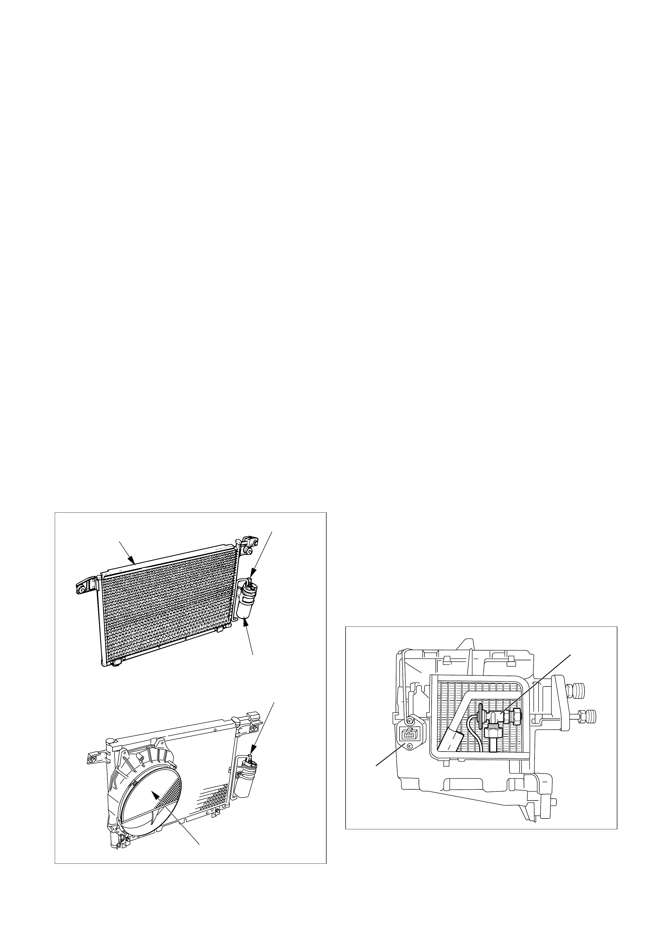
EXPANSION VALVE
This expansion valve (1) is internal pressure type
and it is installed at the evaporator intake port.
The expansion valve converts the high pressure
liquid refrigerant sent from the receiver/drier to a
low pressure liquid refrigerant by forcing it through
a tiny port before sending it to the evaporator (2).
This type of expansion valve consists of a
temperature sensor, diaphragm, ball valve, ball
seat, spring adjustment screw, etc.
The temperature sensor contacts the evaporator
outlet pipe, and converts changes in temperature to
pressure. It then transmits these to the top chamber
of the diaphragm.
The refrigerant pressure is transmitted to the
diaphragms bottom chamber through the external
equalizing pressure tube.
The ball valve is connected to the diaphragm. The
opening angle of the expansion valve is determined
by the force acting on the diaphragm and the spring
pressure.
The expansion valve regulates the flow rate of the
refrigerant. Accordingly, when a malfunction occurs
to this expansion valve, both discharge and suction
pressures get low, resulting in insufficient cooling
capacity of the evaporator.
Pressure switch
Receiver/Drier
Triple pressure switch
Condenser fan
Condenser
1
2
875RY00003
874RY00003
EVAPORATOR
The evaporator cools and dehumidifies the air
before the air enters the vehicle. High-pressure
liquid refrigerant flows through the expansion valve
(1) into the low-pressure area of the evaporator (2).
The heat in the air passing through the evaporator
core is lost to the cooler surface of the core, thereby
cooling the air.
As heat is lost between the air and the evaporator
core surface, moisture in the vehicle condenses on
the outside surface of the evaporator core and is
drained off as water.
When the evaporator malfunctions, the trouble will
show up as inadequate supply of cool air. The
cause is typically a partially plugged core due to
dirt, or a malfunctioning blower motor.
The evaporator core with a laminate louver fin is a
single-sided tank type where only one tank is
provided under the core.
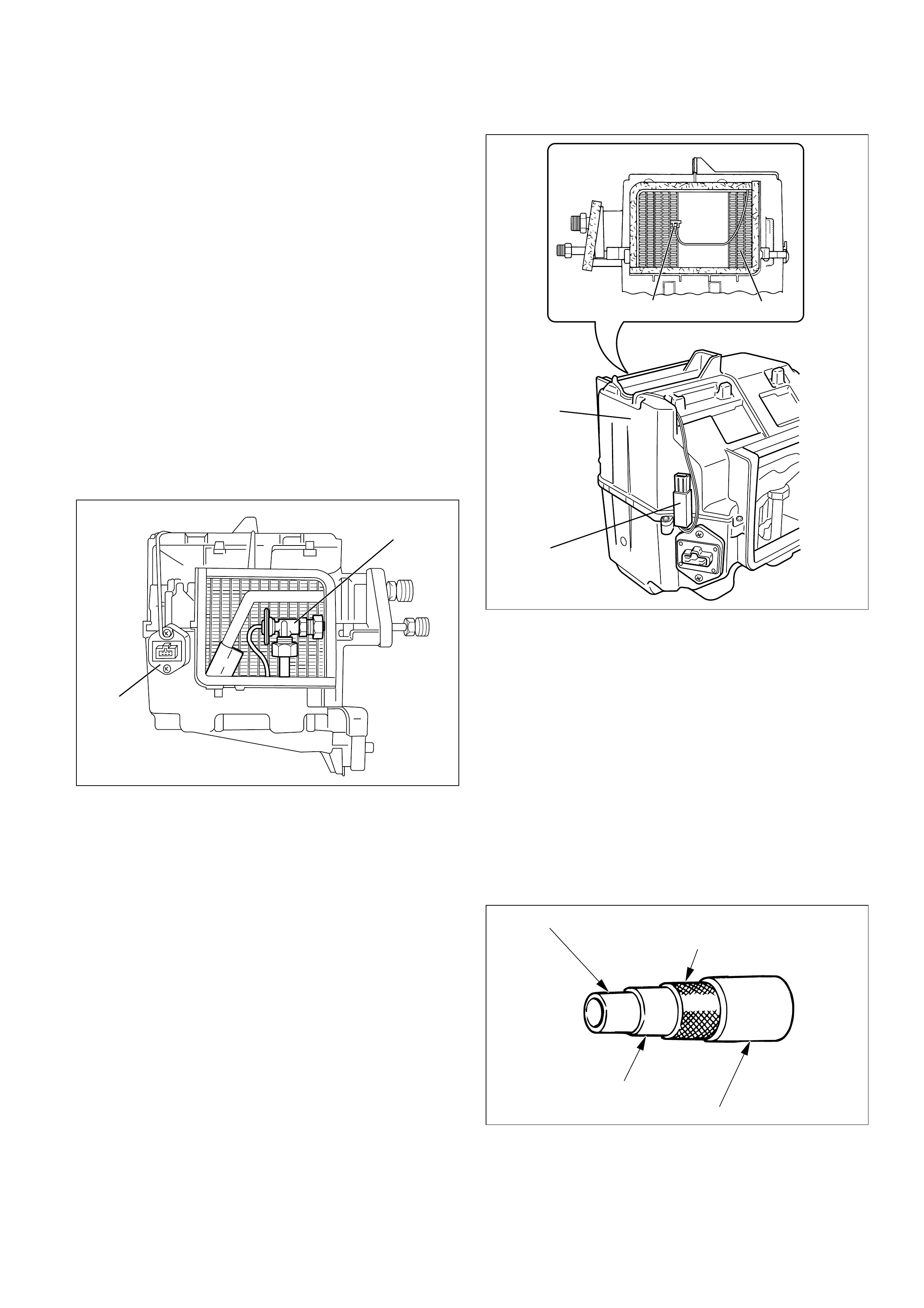
ELECTRONIC THERMOSTAT
The thermostat consists of the thermosensor (1)
and thermostat unit (4) which functions electrically
to reduce the noises being generated while the
system is in operation.
The electronic thermosensor (1) is mounted at the
evaporator core (2) outlet and senses the
temperature of the cool air from the evaporator (3).
Temperature signals are input to the thermostat
unit. This information is compared by the thermo
unit and the results in output to operate the A/C
Thermostat relay and turn the magnetic clutch
“ON” or “OFF” to prevent evaporator freeze-up.
A characteristic of the sensor is that the resistance
decreases as the temperature increases and the
resistance increases as the temperature decreases.
REFRIGERANT LINE
Restrictions in the refrigerant line will be indicated by:
1. Suction line; A restricted suction line will cause
low suction pressure at the compressor, low
discharge pressure and little or not cooling.
2. Discharge line; A restriction in the discharge line
generally will cause the discharge line to leak.
3. Liquid line; A liquid line restriction will be
evidenced by low discharge and suction
pressure and insufficient cooling.
Refrigerant flexible hoses that have a low
permeability to refrigerant and moisture are used.
These low permeability hoses have a special nylon
layer on the inside.
SERVICE CHARGE VALVES
The charging hoses have a quick-joint type fitting,
to reduce refrigerant loss during removal and
installation.
1 2
3
4
Reinforcement layer(Polyester)
Resin layer(Nylon)
Internal rubber layer
External rubber layer
1
2
874RY00003
874RX022
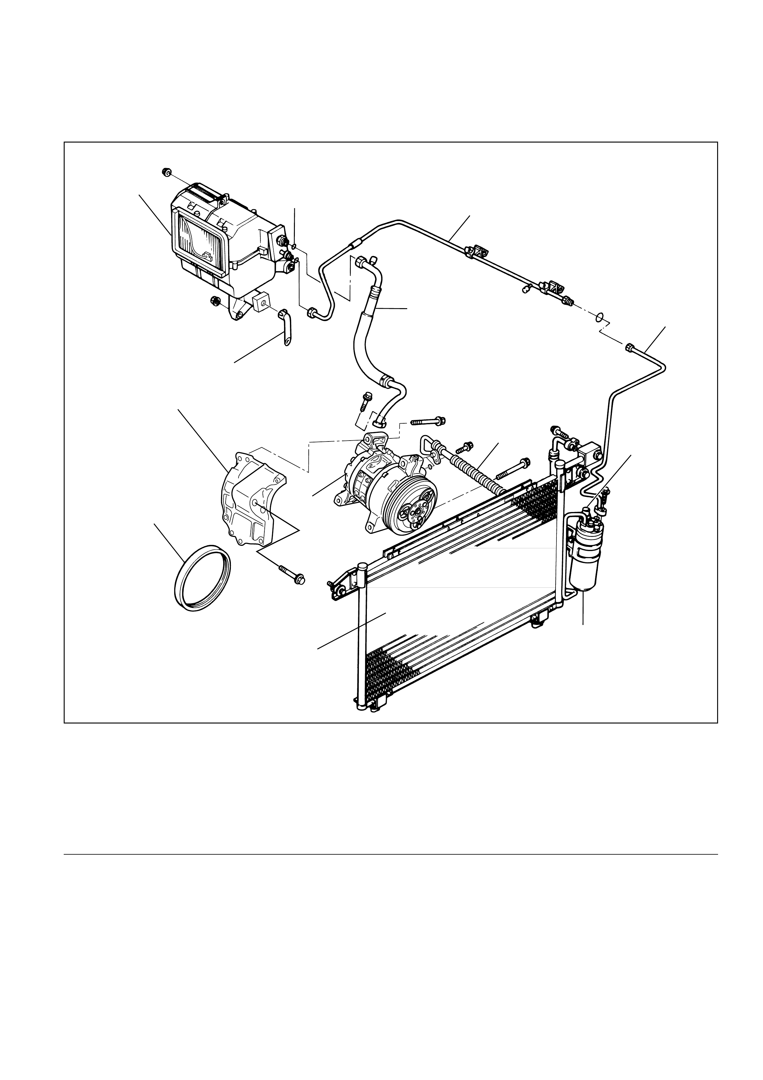
AIR CONDITIONING PARTS
Legend
(1) Liquid Line (High-Pressure Pipe)
(2) Pressure Switch
(3) Receiver Drier
(4) Discharge Line (High-Pressure Hose)
(5) Suction Line (Low-Pressure Hose)
(6) Compressor
(7) Condenser Assembly
(8) Serpentine Belt
(9) Compressor Bracket
(10) Drain Hose
(11) Evaporator Assembly
(12) O-ring
9
6
1
1
4
5
11 12
10
2
3
7
8
6VE1
852RY00006
9
6
12
5
4
11
13
10
14
2
1
3
8
7
852RY00005
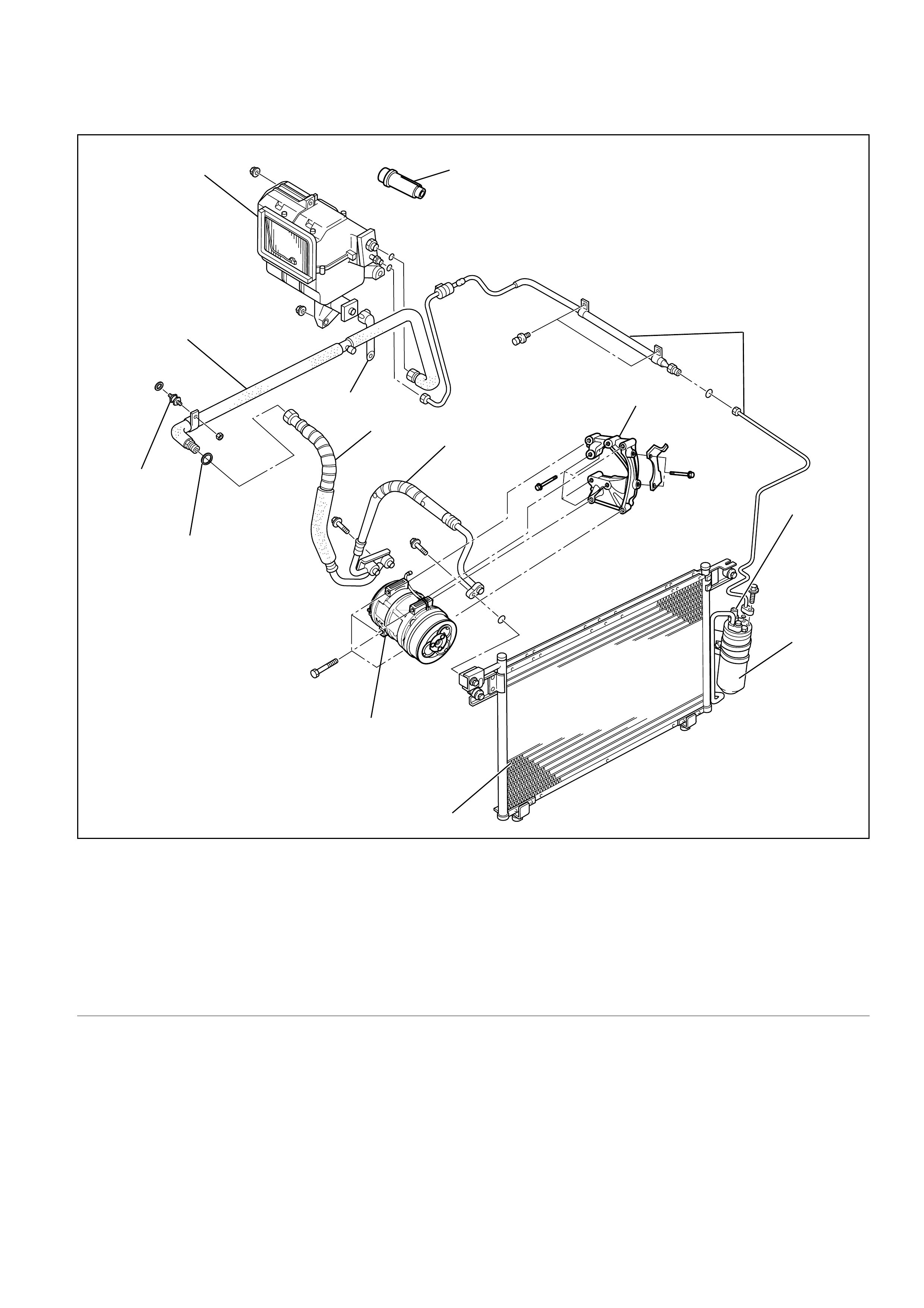
4JX1
Legend
(1) Liquid Line (High- Pressure Pipe)
(2) Pressure Switch
(3) Receiver Drier
(4) Compressor Bracket
(5) Discharge Line (High-Pressure Hose)
(6) Suction Line (Low-Pressure Hose)
(7) Compressor
(8) Condenser Assembly
(9) O-ring
(10) Insulator Pipe
(11) Suction Line (Low Pressure Pipe)
(12) Drain Hose
(13) Evaporator Assembly
(14) A/C Switch
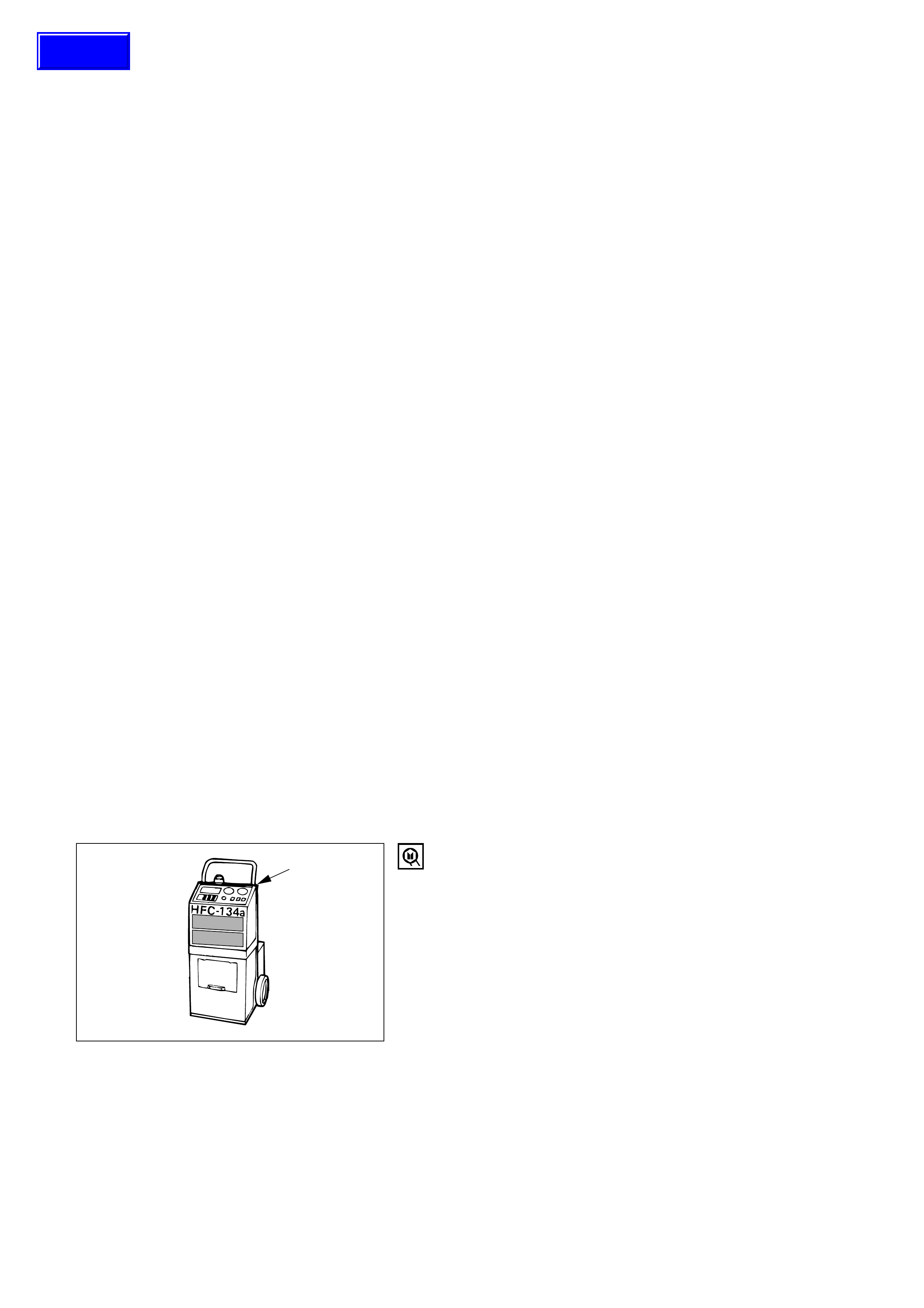
ACR4
1) Using the ACR4
(HFC-134a Refrigerant Recovery/
Recycling/ Recharging/ System) or equivalent to
thoroughly discharge and recover the refrigerant.
ACR4
(115V 60Hz) : 5-8840-0629-0 (J-39500-A)
ACR4
(220-240V 50/60Hz)
: 5-8840-0630-0 (J-39500-220A)
ACR4
(220-240V 50/60Hz Australian model)
: 5-8840-0631-0 (J-39500-220ANZ)
2) Remove and replace the defective part.
3) After evacuation, charge the air conditioning
system and check for leaks.
PRECAUTIONS FOR REPLACEMENT OR REPAIR OF
AIR CONDITIONING PARTS
There are certain procedure, practices and precautions
that should be followed when servicing air conditioning
systems:
• Keep your work area clean.
• Always wear safety goggle and protective gloves
when working on refrigerant systems.
• Beware of the danger of carbon monoxide fumes
caused by running the engine.
• Beware of discharged refrigerant in enclosed or
improperly ventilated garages.
• Always disconnect the negative battery cable and
discharge and recover the refrigerant whenever
repairing the air conditioning system.
• When discharging and recovering the refrigerant, do
not allow refrigerant to discharge too fast; it will draw
compressor oil out of the system.
• Keep moisture and contaminants out of the system.
When disconnecting or removing any lines or parts,
use plugs or caps to close the fittings immediately.
Never remove the caps or plugs until the lines or
parts are reconnected or installed.
• When disconnecting or reconnecting the lines, use
two wrenches to support the line fitting, to prevent
from twisting or other damage.
• Always install new O-rings whenever a connection is
disassembled.
• Before connecting any hoses or lines, apply new
specified compressor oil to the O-rings.
• When removing and replacing any parts which
require discharging the refrigerant circuit, the
operations described in this section must be
performed in the following sequence:
ON-VEHICLE SERVICE
Techline

REPAIR OF REFRIGERANT LEAKS
Refrigerant Line Connections
Install new O-rings, if required. When disconnecting or
connecting lines, use two wrenches to prevent the
connecting portion from twisting or becoming damaged.
When connecting the refrigerant line at the block joint,
securely insert the projecting portion of the joint portion
into the connecting hole on the unit side and secure with a
bolt.
O-ring
Block joint
Apply specified compressor oil to the O-rings prior to
connecting.
CAUTION:
Compressor (PAG) oil to be used varies according to
compressor model. Be sure to apply oil specified for the
model of compressor.
O-rings must be closely aligned with raised portion of
refrigerant line.
Correct Incorrect Incorrect
1
Insert nut into union. First tighten nut by hand as much as
possible. Then, tighten nut to specified torque.
(Refer to “SERVICE INFORMATION” for Fixing Torque in
section 0A)
12
852RY00014
852RY00015
852RY00016
Techline
COMPRESSOR LEAKS
If leaks are located around the compressor shaft seal or
shell, replace or repair the compressor.
RECOVERY, RECYCLING, EVACUATION AND
CHARGING
Handling Refrigerant-134a (HFC-134a)
Air conditioning systems contain HFC-134a.
This is a chemical mixture which requires special
handling procedures to avoid personal injury.
• Always wear safety goggles and protective gloves.
• Always work in a well-ventilated area. Do not weld or
steam clean on or near any vehicle-installed air
conditioning lines or components.
• If HFC-134a should come in contact with any part of
the body, flush the exposed area with cold water and
immediately seek medical help.
• If it is necessary to transport or carry any container of
HFC-134a in a vehicle, do not carry it in the passenger
compartment.
• If it is necessary to fill a small HFC-134a container
from a large one, never fill the container completely.
Space should always be allowed above the liquid for
expansion.
• Keep HFC-134a containers stored below 40 °C (104°F).
LEAK AT REFRIGERANT LINE CONNECTIONS
1) Check the torque on the refrigerant line fitting and, if
too loose, tighten to the specified torque.
•Use two wrenches to prevent twisting and damage
to the Line.
•Do not over tighten.
2) Perform a leak test on the refrigerant line fitting.
3) If the leak is still present, discharge and recover the
refrigerant from the system.
4) Replace the O-rings.
•O-rings cannot be reused. Always replace with
new ones.
•Be sure to apply specified compressor oil to the
new O-rings.
5) Retighten the refrigerant line fitting to the specified
torque.
•Use two wrenches to prevent twisting and damage
to the line.
6) Evacuate, charge and retest the system.
LEAK IN THE HOSE
If the compressor inlet or outlet hose is leaking, the entire
hose must be replaced. Refrigerant hose must not be cut
or spliced for repair.
1) Locate the leak.
2) Discharge and recover the refrigerant.
3) Remove the hose assembly.
•Cap the open connections at once.
4) Connect the new hose assembly.
•Use two wrenches to prevent twisting or damage
to the hose fitting.
•Tighten the hose fitting to the specified torque.
5) Evacuate, charge and test the system.
WARNING
•SHOULD HFC-134a CONTACT YOUR EYE(S),
CONSULT A DOCTOR IMMEDIATELY.
•DO NOT RUB THE AFFECTED EYE(S). INSTEAD,
SPLASH QUANTITIES OF FRESH COLD WATER
OVER THE AFFECTED AREA TO GRADUALLY
RAISE THE TEMPERATURE OF THE
REFRIGERANT ABOVE THE FREEZING POINT.
•OBTAIN PROPER MEDICAL TREATMENT AS
SOON AS POSSIBLE. SHOULD THE HFC-134a
TOUCH THE SKIN, THE INJURY MUST BE
TREATED THE SAME AS SKIN WHICH HAS
BEEN FROSTBITTEN OR FROZEN.
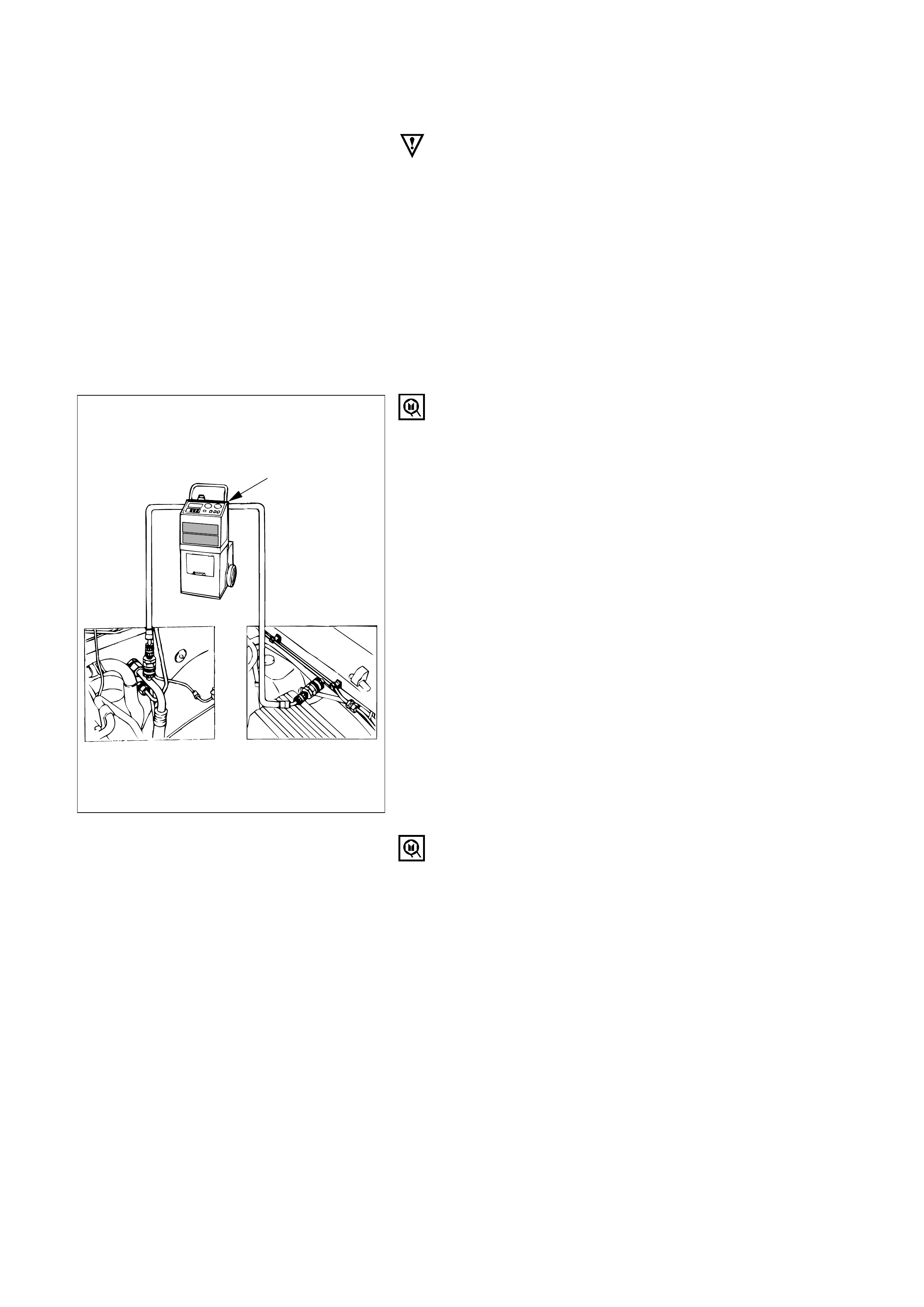
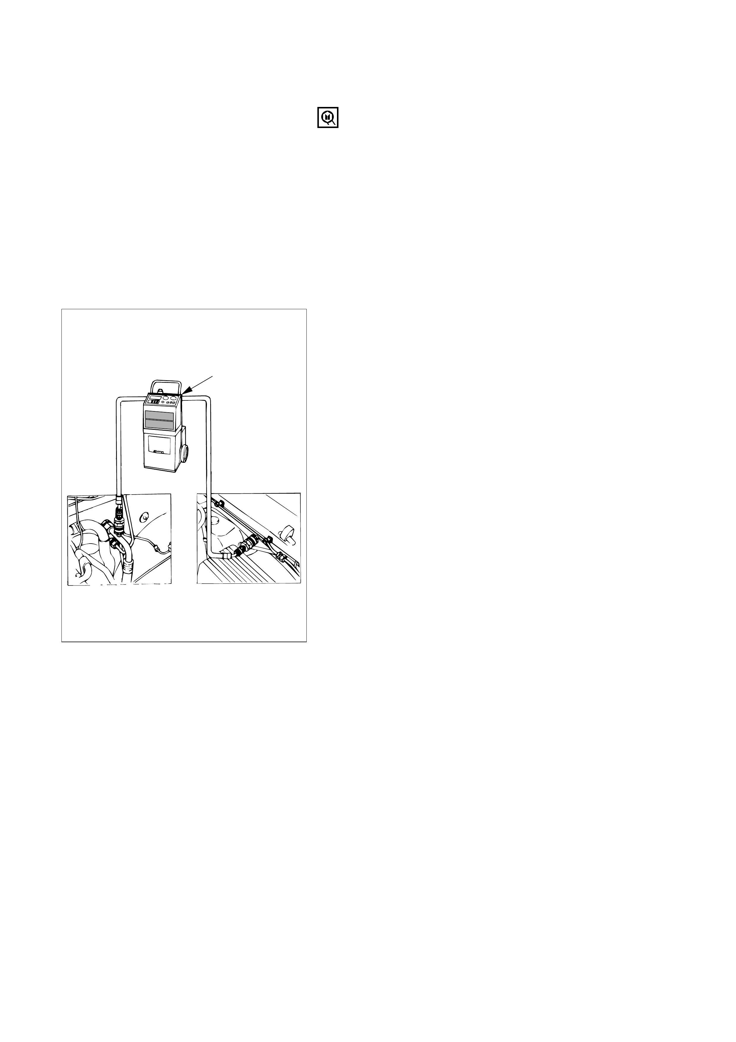
REFRIGERANT RECOVERY
The refrigerant must be discharged and recovered by
using ACR4(HFC-134a Refrigerant Recovery/ Recycling/
Recharging/ System) or equivalent before removing or
mounting air conditioning parts.
ACR4(115V 60Hz) : 5-8840-0629-0 (J-39500-A)
ACR4(220-240V 50/60Hz)
: 5-8840-0630-0 (J-39500-220A)
ACR4(220-240V 50/60Hz Australian model)
: 5-8840-0631-0 (J-39500-220ANZ)
1) Connect the high and low charging hoses of the ACR4
(or equivalent) as shown
2) Recover the refrigerant by following the ACR4
Manufacture’s Instructions.
3) When a part is removed, put a cap or a plug on the
connecting portion so that dust, dirt or moisture
cannot get into it.
ACR4
(Low side) (High side)
HFC 134a
REFRIGERANT RECYCLING
Recycle the refrigerant recovered by ACR4or equivalent.
For the details of the actual operation, follow the steps in
the ACR4Manufacture’s Instructions.
ACR4(115V 60Hz) : 5-8840-0629-0 (J-39500-A)
ACR4(220-240V 50/60Hz)
: 5-8840-0630-0 (J-39500-220A)
ACR4(220-240V 50/60Hz Australian model)
: 5-8840-0631-0 (J-39500-220ANZ)
7) Check to ensure that the pressure does not change
after 10 minutes or more.
•If the pressure changes, check the system for leaks.
•If leaks occur, retighten the refrigerant line
connections and repeat the evacuation steps.
8) If no leaks are found, again operate the vacuum
pump for 20 minutes or more, After confirming that
the gauge manifold pressure is at 750 mmHg(30
inHg), close both hand valves.
9) Close positive shutoff valve.
Stop the vacuum pump and disconnect the center
hose from the vacuum pump.
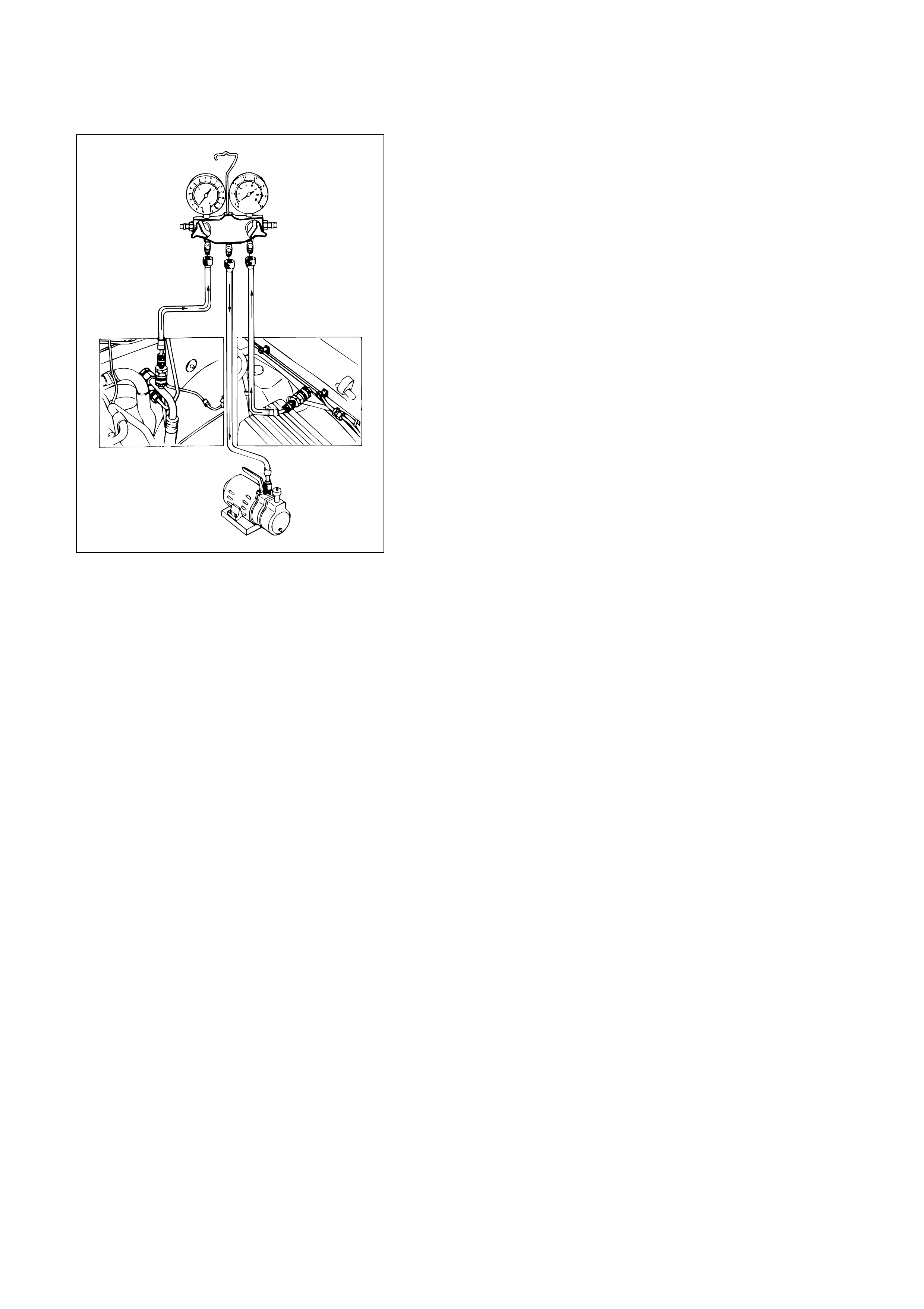
Air and moisture in the refrigerant will cause problems in
the air conditioning system.
Therefore, before charging the refrigerant, be sure to
evacuate air and moisture thoroughly from the system.
1) Connect the gauge manifold.
•High-pressure valve (HI) – Discharge-side
•Low-pressure valve (LOW) – Suction-side
2) Discharge and recover the refrigerant.
3) Connect the center hose of the gauge manifold set to
the vacuum pump inlet.
4) Operate the vacuum pump, open shutoff valve and
then open both hand valves.
5) When the low-pressure gauge indicates approx. 750
mmHg (30 inHg), continue the evacuation for 5
minutes or more.
6) Close both hand valves and stop the vacuum pump.
EVACUATION OF THE REFRIGERANT SYSTEM
NOTE:
Explained below is a method using a vacuum pump. Refer
to ACR4(or equivalent) manufacture’s instructions when
evacuating the system with ACR4(or equivalent)
(Low side) (High side)
CHARGING THE REFRIGERANT SYSTEM
There are various methods of charging refrigerant into the
air conditioning system.
These include using ACR4(HFC-134a Refrigerant
Recovery/ Recycling/ Recharging/ System) or equivalent
and direct charging with a manifold gauge charging
station.
ACR4(115V 60Hz) : 5-8840-0629-0 (J-39500-A)
ACR4(220-240V 50/60Hz)
: 5-8840-0630-0 (J-39500-220A)
ACR4(220-240V 50/60Hz Australian model)
: 5-8840-0631-0 (J-39500-220ANZ)
Charging procedure
•ACR4(or equivalent) method
For the charging of refrigerant recovery by ACR4, follow
the manufacture’s instruction.
ACR4
(Low side) (High side)
HFC 134a
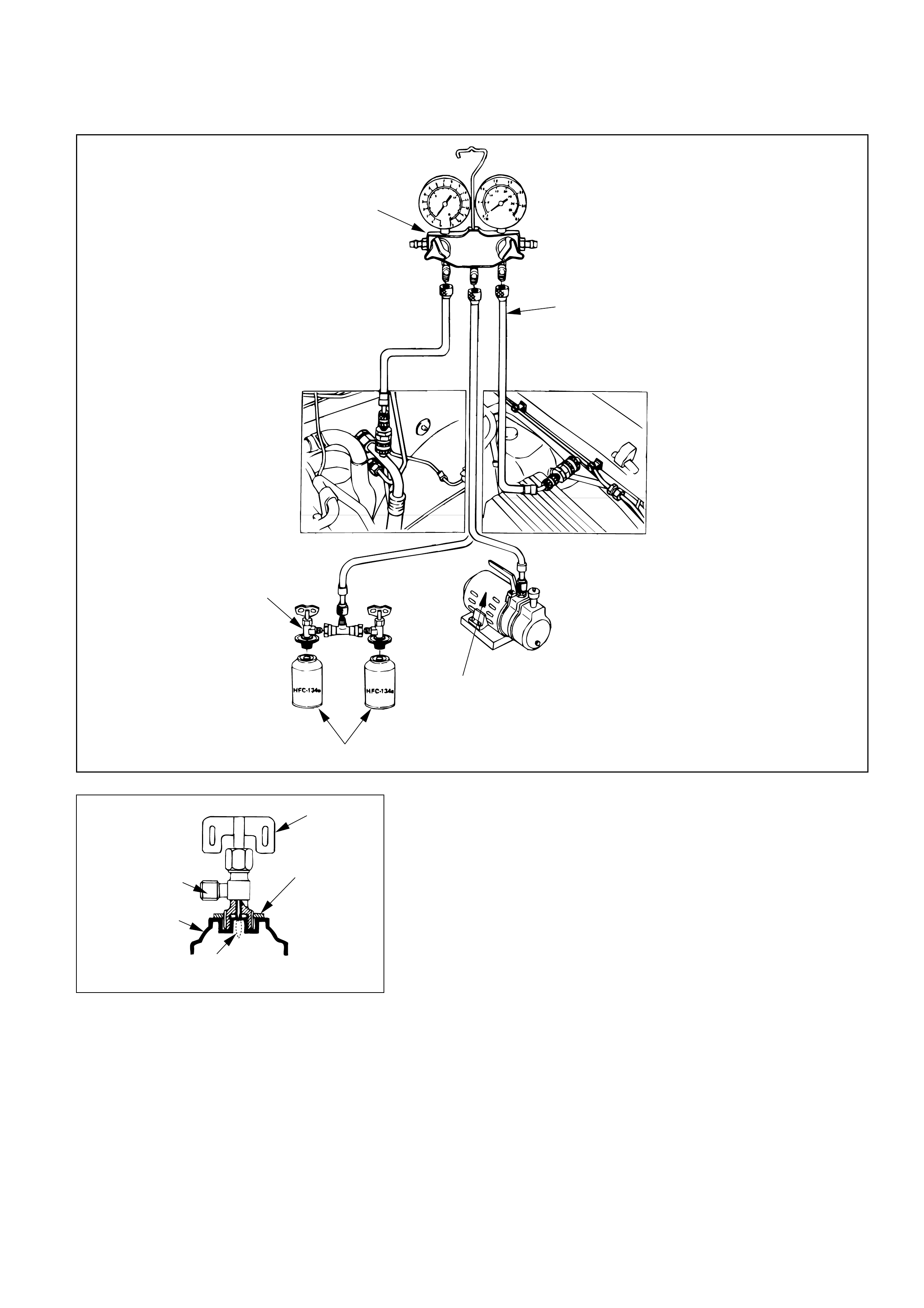
•Direct charging with a manifold gauge charging station
method
Handling the charging valve handle when installing
refrigerant container.
1) Before attaching the charge valve to the refrigerant
container, turn the charge valve handle
counterclockwise until the needle is fully retracted.
2) Turn the plate nut counterclockwise until it reaches its
highest position relative to the charge valve.
3) Install the charge valve onto the refrigerant container.
4) Turn the plate nut clockwise and connect the center
hose of the manifold gauge to the charge valve.
5) Tighten the plate nut sufficiently by hand. Then turn
the charge valve handle clockwise to lower the needle
and bore a hole in the refrigerant container.
6) Turn the charge valve handle counterclockwise to
raise the needle. The refrigerant in the refrigerant
container is charged into the air conditioning system
by the operation of the manifold gauge.
•Be absolutely sure not to reuse the emptied
refrigerant container.
Charge valve handle
Plate nut
Needle
Connection
<Charge valve>
Refrigerant container
Charging hose
Manifold gauge
Vacuum pump
Refrigerant container
Charge valve handle
(Low side) (High side)

1) Make sure the evacuation process is correctly
completed.
2) Connect the center-hose of the manifold gauge to the
refrigerant container.
• Turn the charge valve handle counterclockwise to
purge the charging line and purge any air existing
in the center-hose of the manifold gauge.
3) Open the low-pressure hand valve and charge the
refrigerant about 200 g(0.44 lbs.).
• Make sure the high-pressure hand valve is closed.
• Avoid charging the refrigerant by turning the
refrigerant container upside down.
4) Close the low-pressure hand valve of the manifold
gauge.
• Check to ensure that the degree of pressure does
not charge.
5) Check the refrigerant leaks by using a HFC-134a leak
detector.
• If a leak occurs, repair the leak connection, and
start all over again from the first step of
evacuation.
6) If no leaks are found, open the low-pressure hand
valve of the manifold gauge.Then continue charging
refrigerant to the system.
• When charging the system becomes difficult:
(1) Run the engine at Idling and close the all
vehicle doors.
(2) A/C switch is “ON”.
(3) Set the fan control knob (fan switch) to its
highest position.
WARNING
BE ABSOLUTELY SURE NOT TO OPEN THE HIGH-
PRESSURE HAND VALVE. SHOULD THE HIGH-
PRESSURE HAND VALVE BE OPENED, THE HIGH-
PRESSURE REFRIGERANT GAS WOULD FLOW
BACKWARD, AND THIS MAY CAUSE THE
REFRIGERANT CONTAINER TO BURST.
7) When the refrigerant container is emptied, use the
following procedure to replace it with a new
refrigerant container.
(1) Close the low pressure hand valve.
(2) Raise the needle upward and remove the charge
valve.
(3) Reinstall the charge valve to the new refrigerant
container.
(4) Purge any air existing in the center hose of the
manifold gauge.

8) Charge the system to the specified amount and then
close the low-pressure hand valve.
Refrigerant Amount g(lbs.)
750 (1.65)
DELPH1HD6/HT6 g(lbs.)
600 (1.32)
• A fully charged system is indicated by the sight
glass on the receiver/driver being free of any
bubbles(Refer to “Reading Sight Glass”).
•Check the high and low pressure value of the
manifold gauge.
•Check for refrigerant leaks by using a HFC-134a
leak detector.
Immediately after charging refrigerant, both high and low
pressures are slightly high and to the left of the gauge, but
they settle down to the guide pressure valves as shown
below:
•Ambient temperature; 25 ∼30°C (77 ∼86°F)
•Guide pressure
High-pressure side;
Approx. 1373 – 1863 kPa (14 – 19 kg·cm2/ 199 – 270 PSI)
Low-pressure side;
Approx. 147 – 294 kPa (1.4 – 3.0 kg·cm2/ 21 – 43 PSI)
9) Close the low pressure hand valve and charge valve
of the refrigerant container.
10) Stop the air conditioning and the engine.
11) Disconnect the high and low pressure hoses from the
manifold gauge fittings.
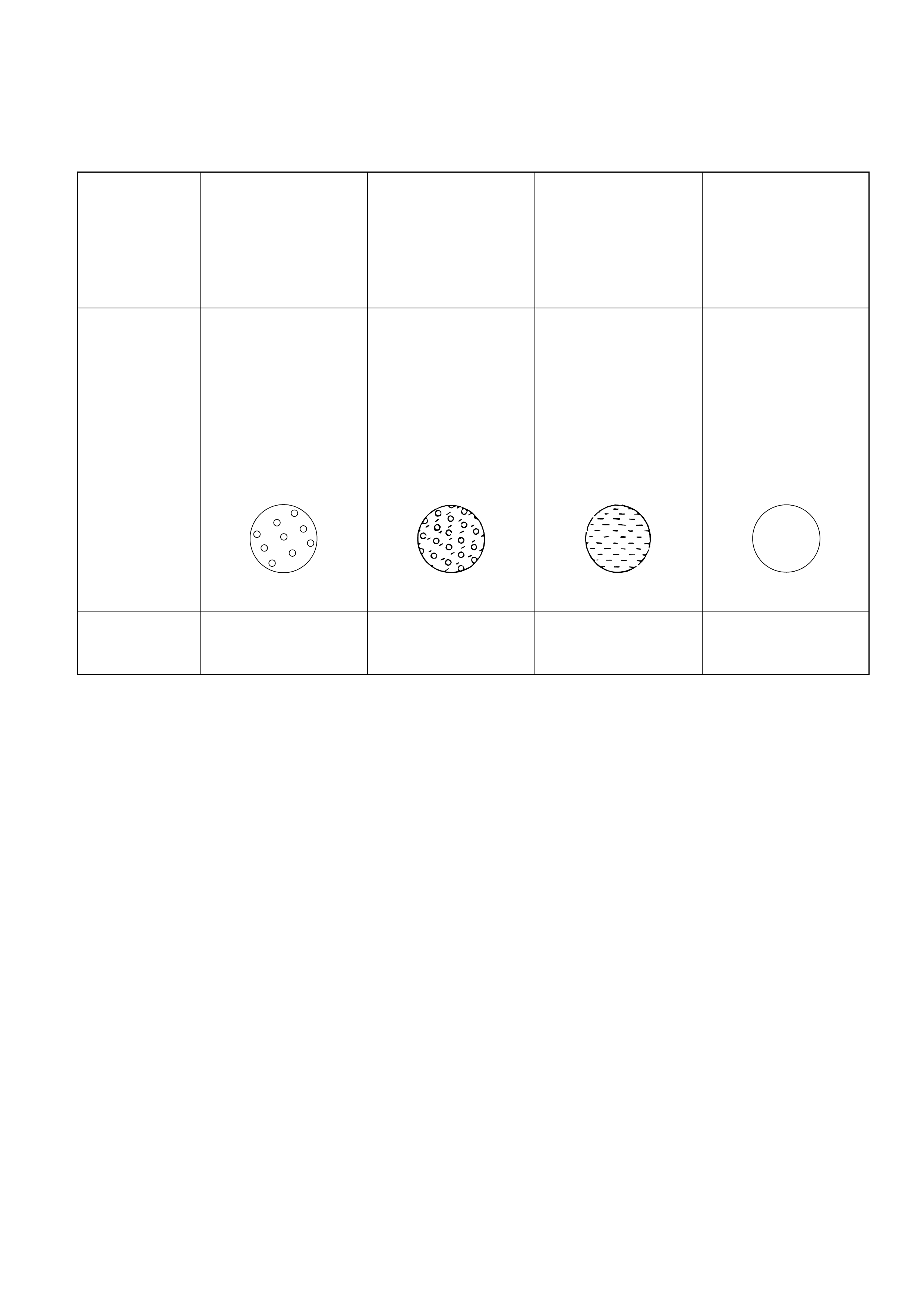
Almost transparent.
A flow of bubbles
can be seen, but
they disappear
when the throttle is
opened.
The sight glass provides accurate diagnosis only under the following conditions.
If the vehicle can be tested under these conditions, check the sight glass appearance and compare to the
chart.
* Engine speed Idling
* A/C switch “ON”
* Blower fan operating at highest speed
* Air source selector lever at “RECIRC”
* Temperature control knob at coldest position
* Ambient temperature below 30°C (86°F) and humidity below 70% (See NOTE 1)
* High side pressure less than 1863 kPa (19 kg·cm2/ 270 PSI) (See NOTE 2)
NOTE 1
If the vehicle cannot be moved to a testing location that meets these specifications, then the sight glass
cannot be used for diagnosis. You must discharge and recover the refrigerant, then recharge the system
with the specified amount of refrigerant. Then continue checking the system performance.
NOTE 2
If the high side pressure is greater than stated, the sight glass cannot be used for diagnosis. You must
discharge and recover the refrigerant, then recharge the system with the specified amount of refrigerant.
Then continue checking system performance.
Reading Sight Glass
High and low
pressure pipe
temperature
Sight glass
condition
Air condi-
tioner cycle
condition
The high pressure
pipe is hot and the
low pressure pipe is
cold. There is a dis-
tinct difference in
temperature bet-
ween them.
OK
The high pressure
pipe is warm and
the low pressure
pipe is cool. There
is no great dif-
ference in tempera-
ture between them.
A flow of bubbles
always can be seen.
It appears some-
times transparent,
and sometimes
frothy.
NG
(Not enough
refrigerant)
There is little dif-
ference in tempera-
ture between the
high pressure pipe
and the low press-
ure pipe.
Something like fog
faintly can be seen.
NG
(Almost no
refrigerant)
The high pressure
pipe is hot and the
low pressure pipe is
slightly warm.
There is a difference
in temperature bet-
ween them.
Even at idle with the
fan at “HI” (with the
window fully open),
the bubbles cannot
be seen.
NG
(Too much
refrigerant)
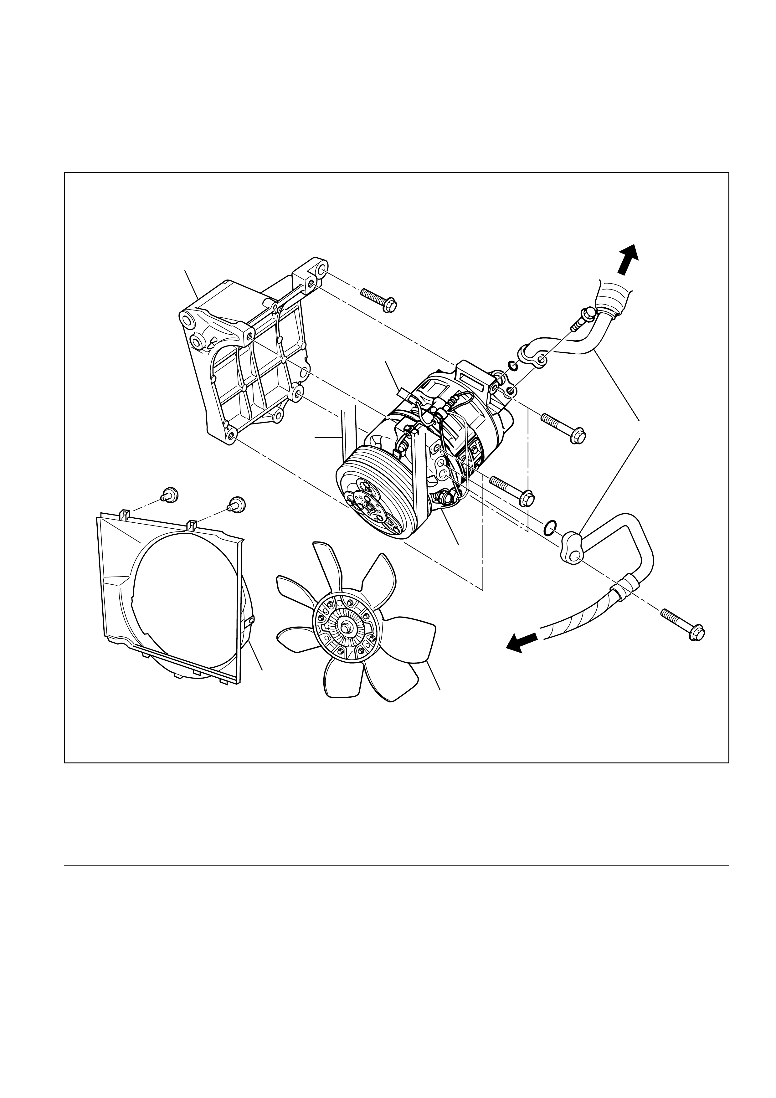
Legend
(1) Magnetic Clutch Harness Connector
(2) To Evaporator
(3) Refrigerant Line Connector
(4) To Condenser
(5) Compressor
(6) Serpentine Belt
(7) Radiator Fan
(8) Radiator Fan Shroud
(9) Compressor Bracket
COMPRESSOR ASSEMBLY AND ASSOCIATED PARTS
6VE1
3
4
2
5
7
8
9
1
6
852RY00007
Removal
1. Disconnect the battery ground cable.
2. Discharge and recover refrigerant.
• Refer to Refrigerant Recovery in this section.
3. Disconnect magnetic clutch harness connector.
4. Remove radiator fan shroud.
5. Remove radiator fan.
•When the fan is removed, be sure to tighten
the fan fixing nuts temporarily to their original
positions.
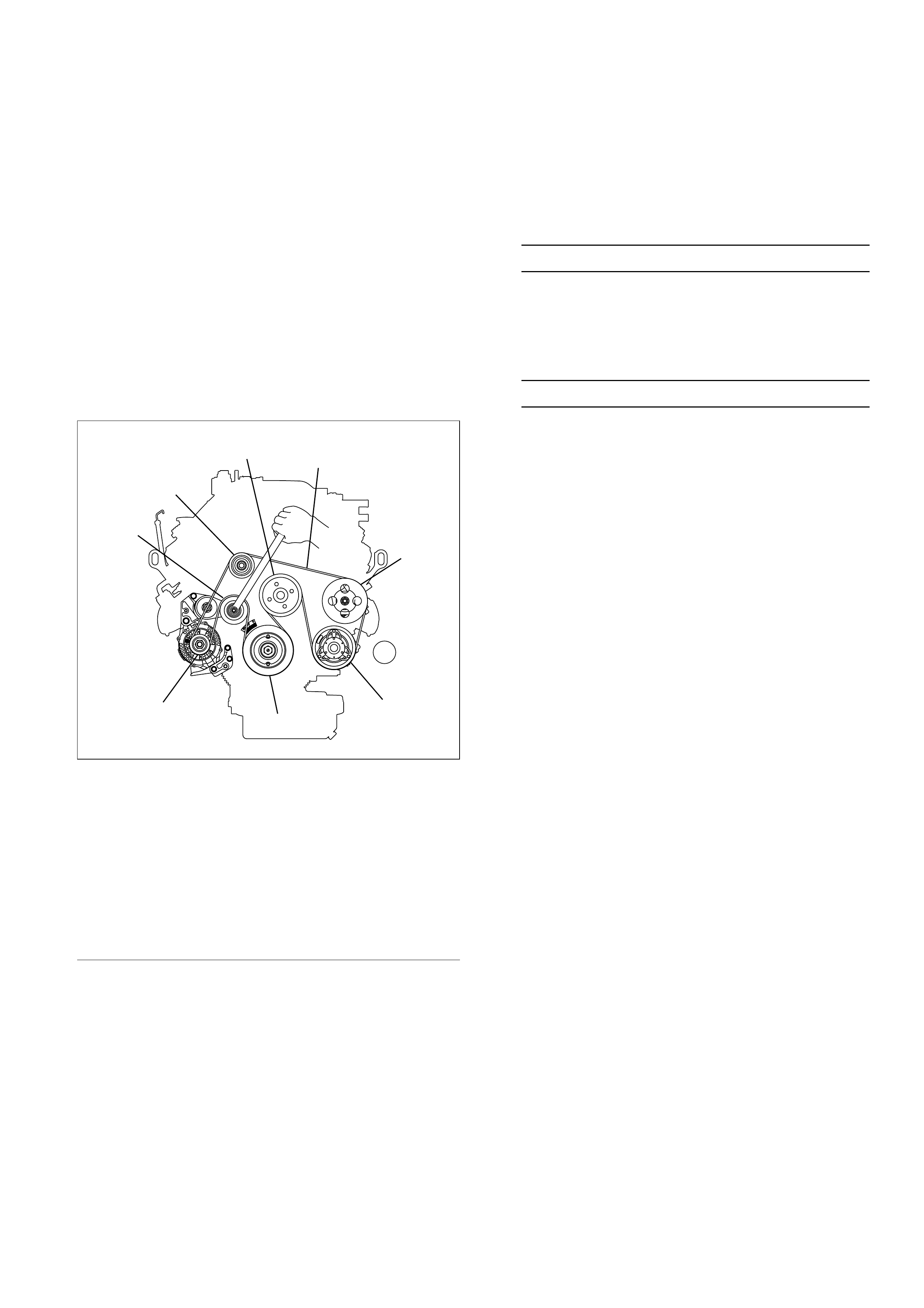
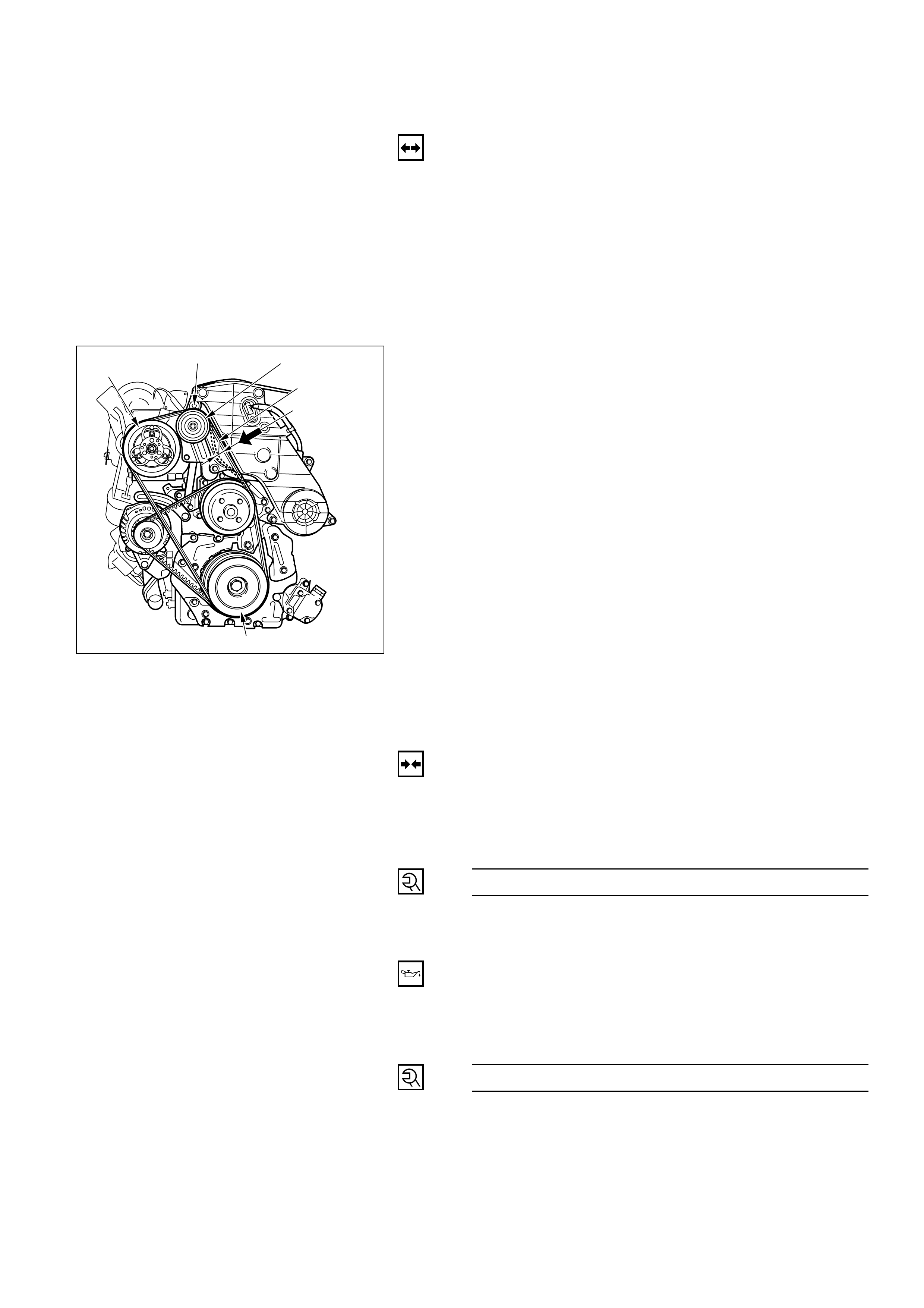
6. Remove serpentine belt.
•Move serpentine belt tensioner to loose side
using wrench, then remove serpentine belt.
Legend
(1) Tensioner
(2) Idle Pulley
(3) Cooling Fan Pulley
(4) Serpentine Belt
(5) Power Steering Oil Pump
(6) Air Conditioner Compressor
(7) Crankshaft Pulley
(8) Generator
7. Disconnect refrigerant line connector.
•When removing the line connector, the
connecting part should immediately be
plugged or capped to prevent foreign matter
from being mixed into the line.
8. Remove compressor.
Installation
1. Install compressor.
•Tighten the compressor fixing bolts to the
specified torque.
Compressor Fixing Torque N·m (kg·m / lb·ft)
19 (1.9 / 14)
2. Connect refrigerant line connector.
•Tighten the refrigerant line connector fixing
bolts to the specified torque.
Refrigerant Line Bolt Torque N·m (kg·m / lb·ft)
15 (1.5 / 11)
•O-rings cannot be reused. Always replace with
new ones.
•Be sure to apply new compressor oil to the O-
rings when connecting refrigerant lines.
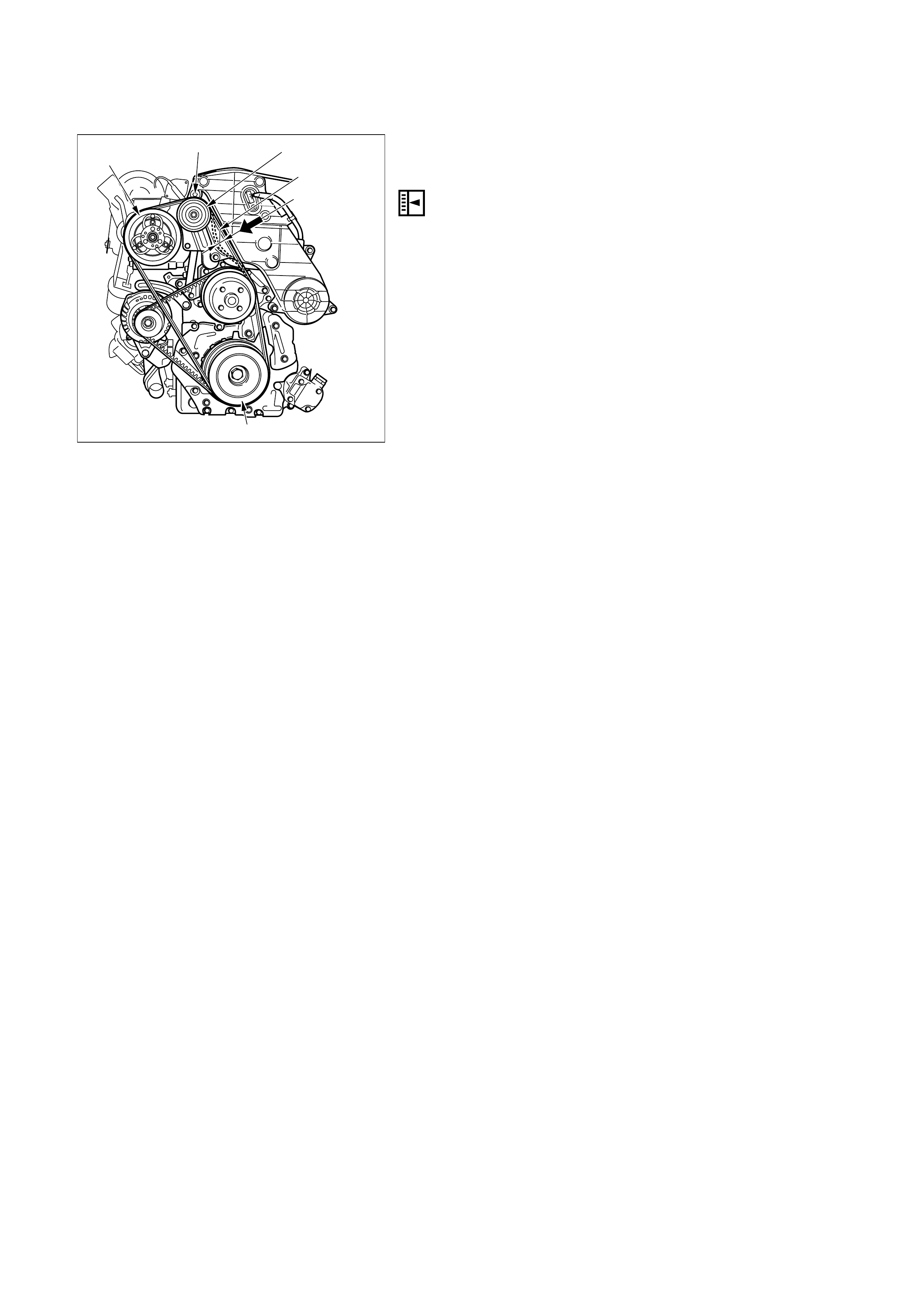
3. Install serpentine belt.
•Move serpentine belt tensioner to loose side
using wrench, then install serpentine belt to
normal position.
4. Install radiator fan.
5. Install radiator fan shroud.
6. Connect magnetic clutch harness connector.
34
2
7
86
1
5
850RX003
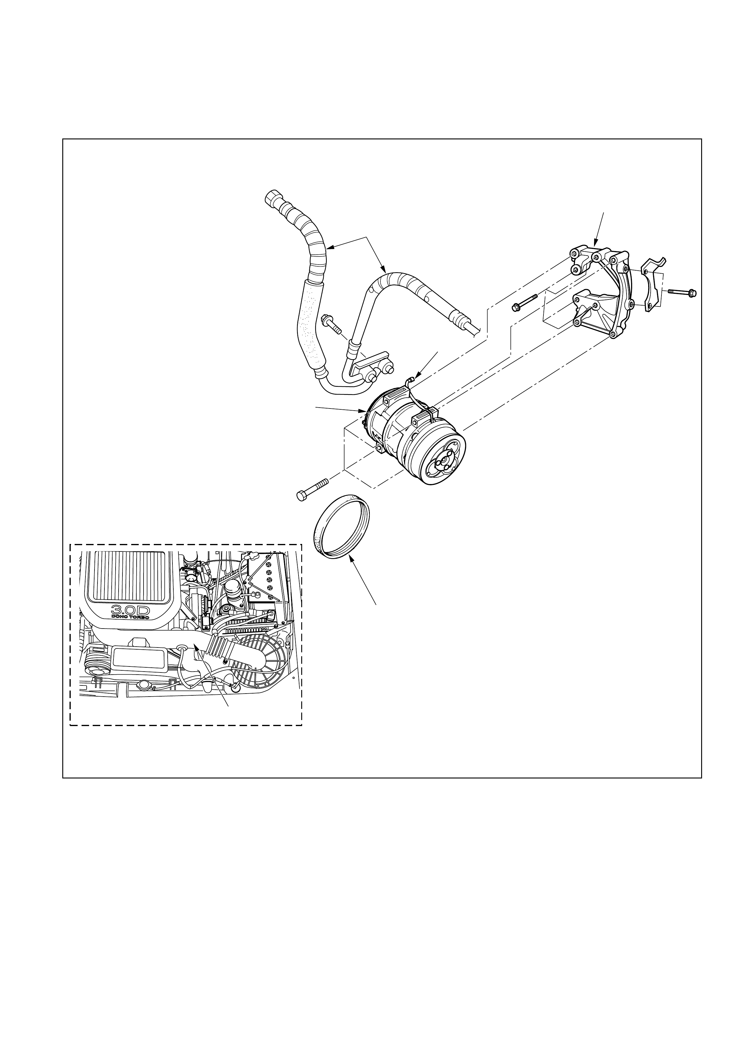
Removal Steps
1. Air duct
2. Compressor bracket
3. Magnetic clutch harness
connector
4. Compressor
5. Drive belt
6. Refrigerant line connector
Installation Steps
To install, follow the removal steps in the
reverse order.
4JX1 ENGINE
1
5
4
6
3
2
852RY00011
REMOVAL
Preparation:
• Battery ground cable
• Discharge and recover refrigerant (Refer to
“REFRIGERANT RECOVERY” in this section)
1. Air Duct (Turbo to air cleaner)
Cover up the air duct connecting portion to prevent
foreign materials from getting into the turbo and the
air cleaner.
2. Magnetic Clutch Harness Connector
3. Drive Belt
Loosen the power steering pump unit fixing bolts,
then loosen the drive belt adjustment bolt and
remove the drive belt.
4. Refrigerant Line Connector
5. Compressor
Compressor
Tension adjustment bolt Tension pulley
14~17mm
(0.55-0.67in)
98N{10kgf}
Crank shaft pulley
INSTALLATION
5. Compressor
Tighten the compressor fixing bolts to the specified
torque.
Compressor Bolt Torque N·m (kg·m / lb·ft)
40 (4.1 / 30)
4. Refrigerant Line Connector
•O-rings cannot be reused. Always replace with new
ones.
•Be sure to apply new compressor oil to the O-rings
when connecting refrigerant lines.
•Tighten the refrigerant line connector to the
specified torque.
Refrigerant Line Bolt Torque N·m (kg·m / lb·ft)
27 (2.8 / 20)
850RY00007
3. Drive Belt
1) Temporary tighten the power steering pump unit
fixing bolts.
2) Push the drive belt when the force of 98N {10kgf}.,
and adjust the drive belt tension by tightening
drive belt tension adjustment bolt, till the 14 ∼17
mm (0.55 ∼0.67 in) of deflection of the belt is
obtained. Then tighten the power steering pump
fixing bolts.
2. Magnetic Clutch Harness Connector
1. Air Duct (Turbo to air cleaner)
Compressor
Tension adjustment bolt Tension pulley
14~17mm
(0.55-0.67in)
98N{10kgf}
Crank shaft pulley
850RY00007

CONDENSER ASSEMBLY (SHOWN WITHOUT CONDENSER FAN)
1
2
1
4
3
5
6
875RW001
Legend
(1) Refrigerant Line
(2) Pressure Switch Connector
(3) Front Bumper Assembly
(4) Radiator Grille
(5) Engine Hood Front End Stay
(6) Condenser Assembly
REMOVAL
1. Disconnect the battery ground cable.
2. Discharge and recover refrigerant.
• Refer to Refrigerant Recovery in this section.
3. Remove radiator grille.4. Remove front bumper assembly.• Refer to Bumpers in Body and Accessories section.5. Remove engine hood front end stay.
6. Disconnect pressure switch connector.
7. Disconnect refrigerant line.
•When removing the line connector, the connecting
part should immediately be plugged or capped to
prevent foreign matter from being mixed into the
line.
8. Remove condenser assembly.
•Handle with care to prevent damaging the
condenser or radiator fin.
•Be sure to apply new compressor oil to the O-rings
when connecting the refrigerant line.
INSTALLATION
1. Install condenser assembly.
•If installing a new condenser, be sure to add 30cc
(1.0 fl. oz.) of new compressor oil to a new one.
•Tighten the condenser fixing bolts to the specified
torque.
Condenser Fixing Torque N·m (kg·m / lb·in)
6 (0.6 / 52)
2. Connect refrigerant line.
•Tighten the inlet line connector fixing bolt to the
specified torque.
Inlet Line Torque N·m (kg·m / lb·ft)
15 (1.5 / 11)
•Tighten the outlet line connector fixing bolt to the
specified torque.
Outlet Line Torque N·m (kg·m / lb·in)
6 (0.6 / 52)
•O-rings cannot be reused. Always replace with new
ones.
•Be sure to apply new compressor oil to the O-rings
when connecting the refrigerant line..
3. Connect pressure switch connector.
4. Install engine hood front end stay.
5. Install front bumper assembly.
6. Install radiator grille.
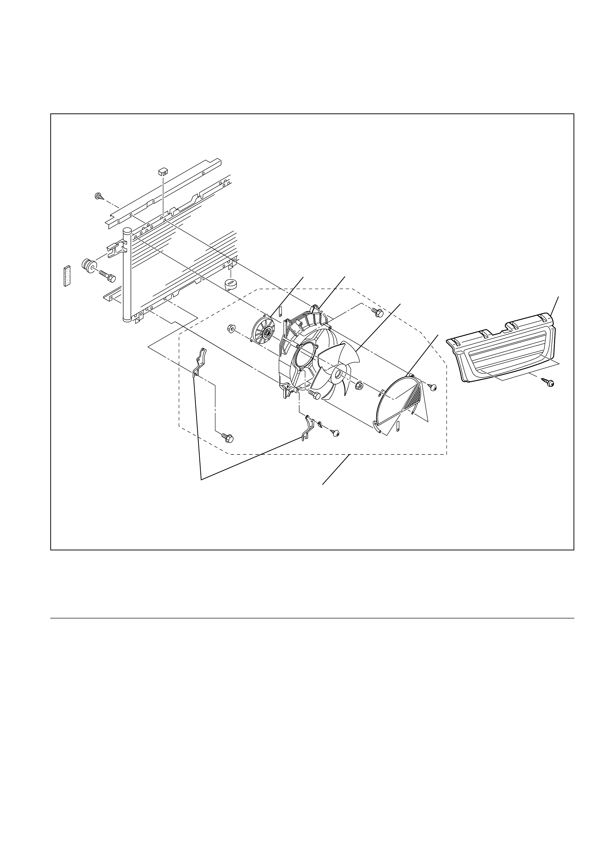
CONDENSER FAN MOTOR
Removal Steps
(1) Condenser Fan Motor
(2) Fan Motor Shroud
(3) Motor Fan
(4) Condenser Unit Net
(5) Radiator Grille
(6) Condenser Fan Assembly
(7) Shroud Bracket
5
4
3
2
1
76
875RY00002

Removal
1. Disconnect the battery ground cable.
2. Discharge and recover refrigerant.
• Refer to Refrigerant Recovery in this section.
3. Remove radiator grille.
4. Remove condenser fan assembly.
•Disconnect the fan motor connector and
remove the 4 fixing bolts.
5. Remove condenser unit net.
•Remove the 4 fixing screws.
6. Remove motor fan.
7. Remove condenser fan motor.
Installation
To install, follow the removal steps in the reverse
order, noting the following point.
1. Route the fan motor harness in its previous
position and fix it securely with clip and bracket.
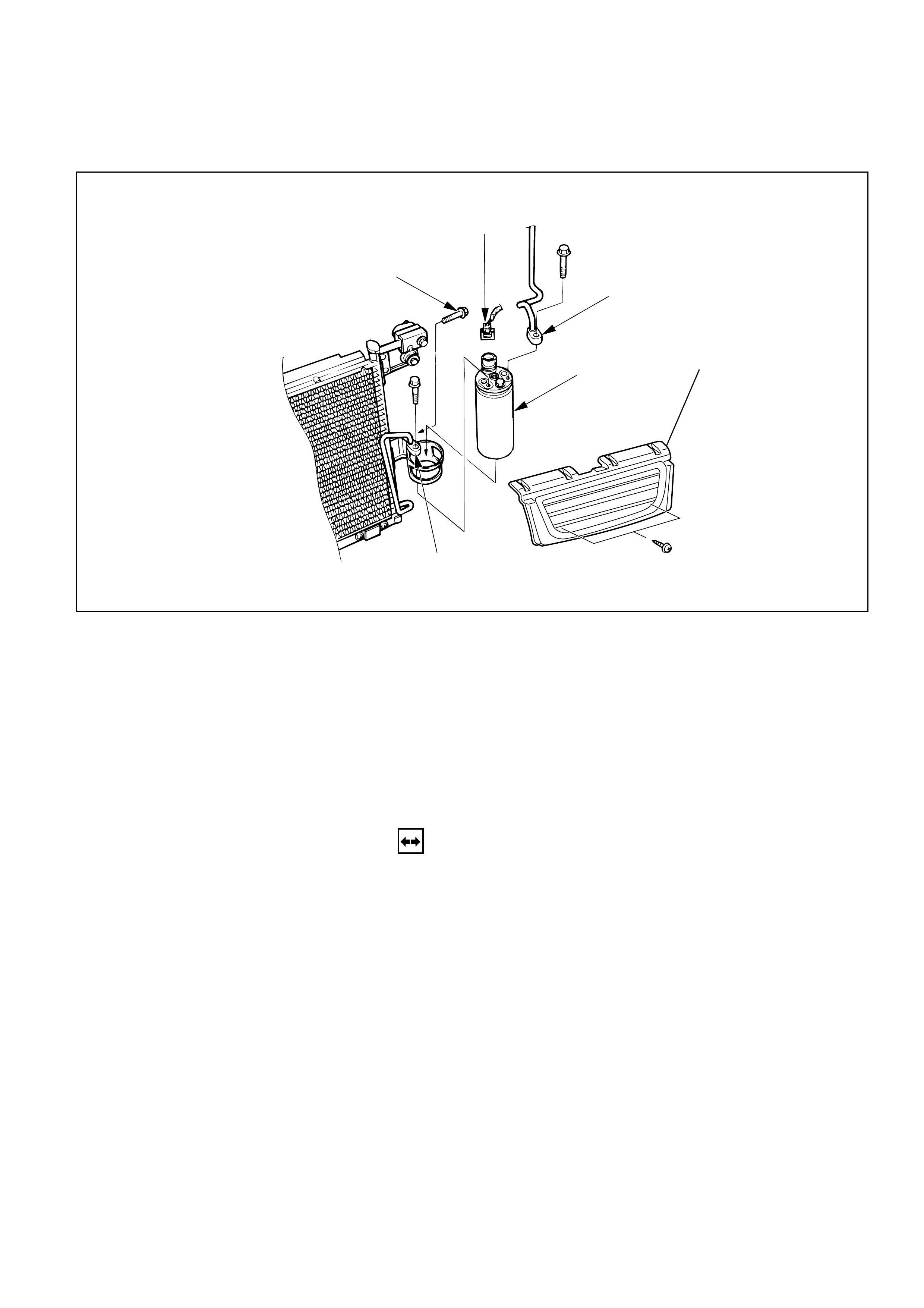
Removal Steps
1. Radiator grille
2. Pressure switch connector
3. Refrigerant line
4. Bracket bolt
5. Receiver/drier
Installation Steps
To install, follow the removal steps in the
reverse order.
RECEIVER/DRIER
3
3
5
2
4
1
REMOVAL
Preparation:
• Disconnect the battery ground cable• Discharge and recover refrigerant (Refer to“REFRIGERANT RECOVERY” in this section.)
1. Radiator Grille
2. Pressure Switch Connector
3. Refrigerant Line
When removing the line connected part, the
connecting part should immediately be plugged or
capped to prevent foreign matter from being mixed
into the line.
4. Bracket Bolt
5. Receiver/Drier
Loosen the bolt, then, using care not to touch or bend
the refrigerant line, carefully pull out the receiver/
drier.
INSTALLATION
To install, follow the removal steps in the reverse order,
noting the following points:
1. If installing a new receiver/drier, be sure to add 30 cc
(0.8 Imp fl oz) of new compressor oil to a new one.
2. Put the receiver/drier in the bracket, and connect with
the refrigerant line. Check that no excessive force is
imposed on the line. Fasten the bracket bolt to the
receiver/drier.
3. Tighten the line to the specified torque.
Refrigerant Line Bolt Torque N·m (kg·m / lb·in)
6 (0.6 / 52)
4. O-rings cannot be reused. Always replace with new
ones.
5. Be sure to apply new compressor oil to the O-rings
when connecting refrigerant line.
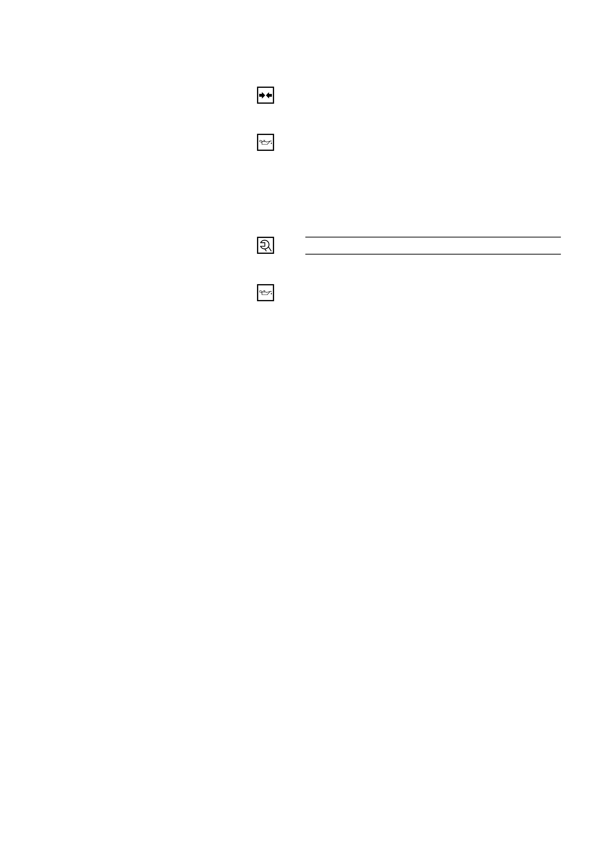
Removal Steps
1. Radiator grille
2. Pressure switch connector
3. Pressure switch
Installation Steps
To install, follow the removal steps in the
reverse order.
PRESSURE SWITCH
2
3
1
REMOVAL
Preparation:
• Disconnect the battery ground cable• Discharge and recover refrigerant (Refer to“REFRIGERANT RECOVERY” in this section.)
1. Radiator Grille
2. Pressure Switch Connector
3. Pressure Switch
When removing the switch connected part, the
connecting part should immediately be plugged or
capped to prevent foreign matter from being mixed
into the line.
INSTALLATION
To install, follow the removal steps in the reverse order,
noting the following points:
1. O-ring cannot be reused. Always replace with a new
one.
2. Be sure to apply new compressor oil to the O-ring
when connecting pressure switch.
3. Tighten the pressure switch to the specified torque.
Pressure Switch Torque N·m (kg·m / lb·in)
13 (1.3 / 113)
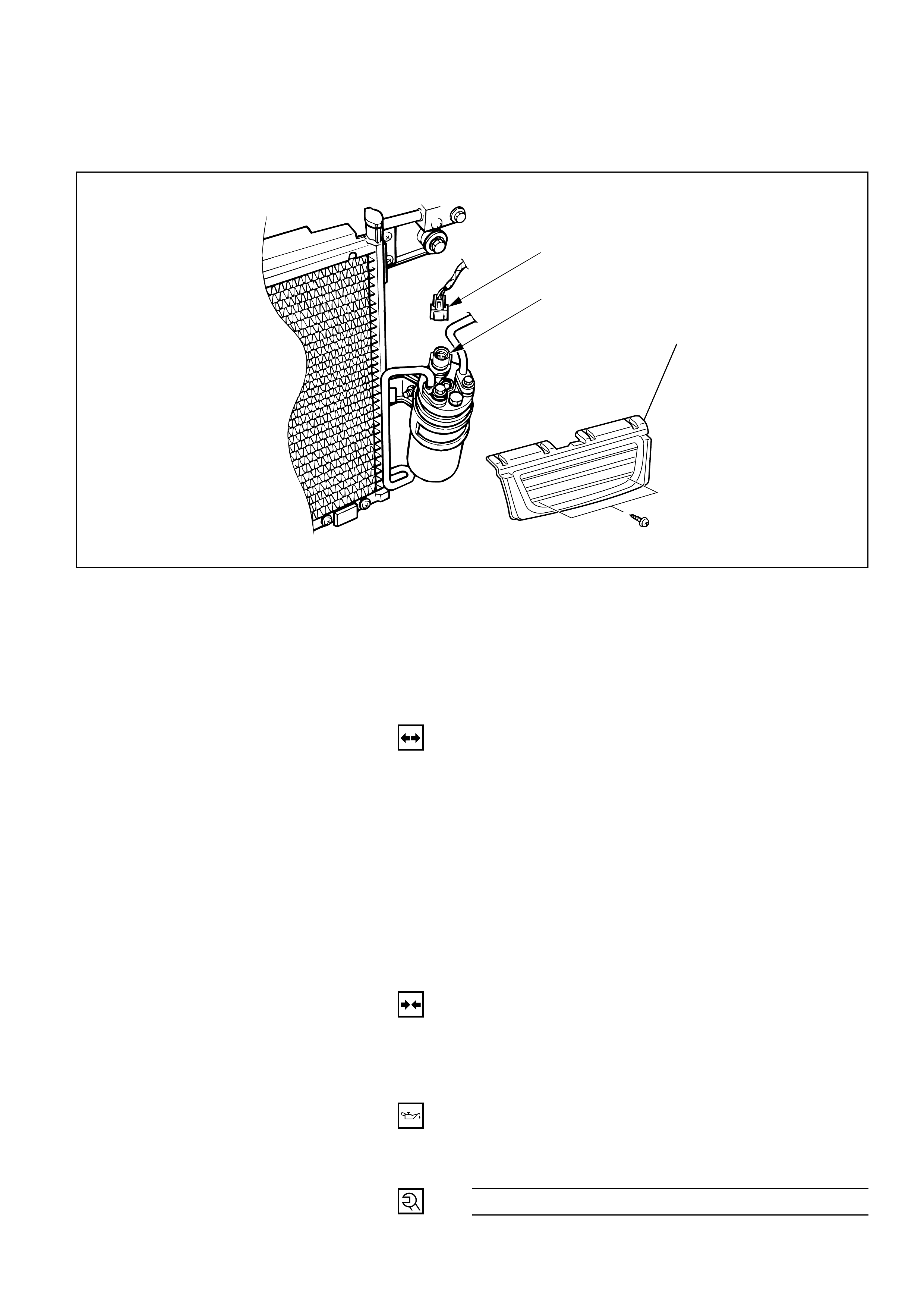
Removal Steps
1. Front console assembly
2. Lower cluster assembly
3. Glove box
4. Instrument panel passenger
lower cover assembly
5. Passenger knee bolster
reinforcement assembly
6. Resistor and electronic
thermostat connector
7. Drain hose
8. Refrigerant line
9. Evaporator assembly
Installation Steps
To install, follow the removal steps in the
reverse order.
EVAPORATOR ASSEMBLY
1
2
34
5
6
7
8
9
This illustration is based on LHD
Electronic thermostat
Resistor
850RW00001
REMOVAL
Preparation:
• Disconnect the battery ground cable
• Discharge and recover refrigerant (Refer to
“REFRIGERANT RECOVERY” in this section.)
1. Front Console Assembly
2. Lower Cluster Assembly
3. Glove Box
4. Instrument Panel Passenger Lower Cover Assembly
5. Passenger Knee Bolster Reinforcement Assembly
• Refer to Section 1 “BODY” for INSTRUMENT
PANEL ASSEMBLY removal procedure.
6. Resistor and Electronic Thermostat Connector
7. Drain Hose
8. Refrigerant Line
•Use a back-up wrench when disconnecting and
reconnecting the refrigerant lines.
•When removing the refrigerant line connected part,
the connecting part should immediately be
plugged or capped to prevent foreign matter from
being mixed into the line.
9. Evaporator Assembly
INSTALLATION
To install, follow the removal steps in the reverse order,
noting the following points:
1. To install a new evaporator assembly, add 50cc
(1.4 Imp fl oz) of new compressor oil to a new core.
2. Tighten the refrigerant outlet line to the specified
torque.
Outlet Line Torque N·m (kg·m / lb·ft)
25 (2.5 / 18)
3. Tighten the refrigerant inlet line to the specified
torque.
Inlet Line Torque N·m (kg·m / lb·ft)
15 (1.5 / 11)
4. O-rings cannot be reused. Always replace with new
ones.
5. Be sure to apply new compressor oil to the O-rings
when connecting lines.
Electronic thermostat
connector
Resistor connector
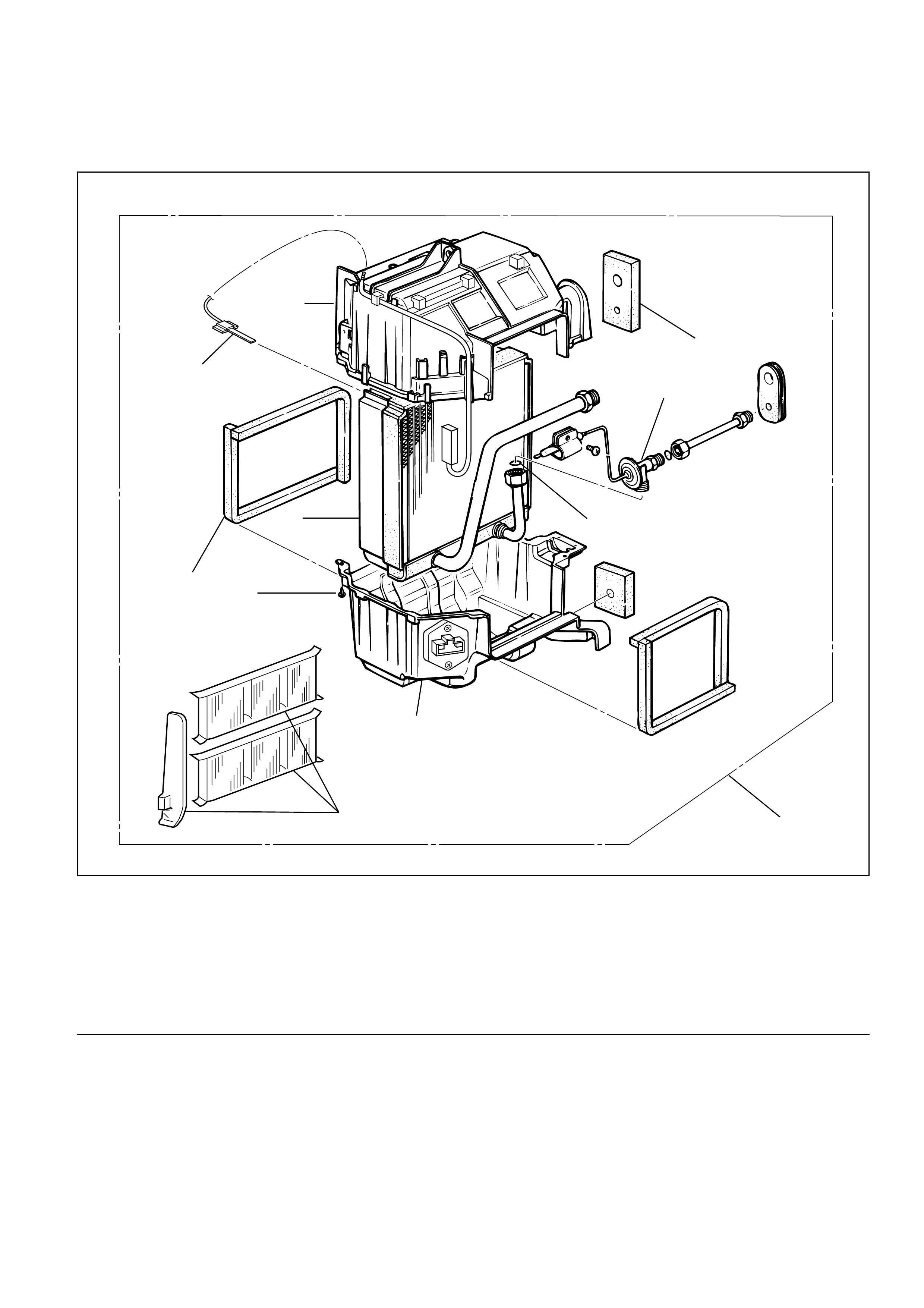
Legend
(1) Lining
(2) Expansion Valve
(3) O-ring
(4) Lower Case
(5) Evaporator Assembly
(6) Pollen Filter
(7) Attaching Screw
(8) Lining
(9) Evaporator Core
(10) Electronic Thermostat
(11) Upper Case
EVAPORATOR CORE AND/OR EXPANSION VALVE
This illustration is based on LHD
8
1
2
3
5
4
6
7
9
11
10
874RY00012
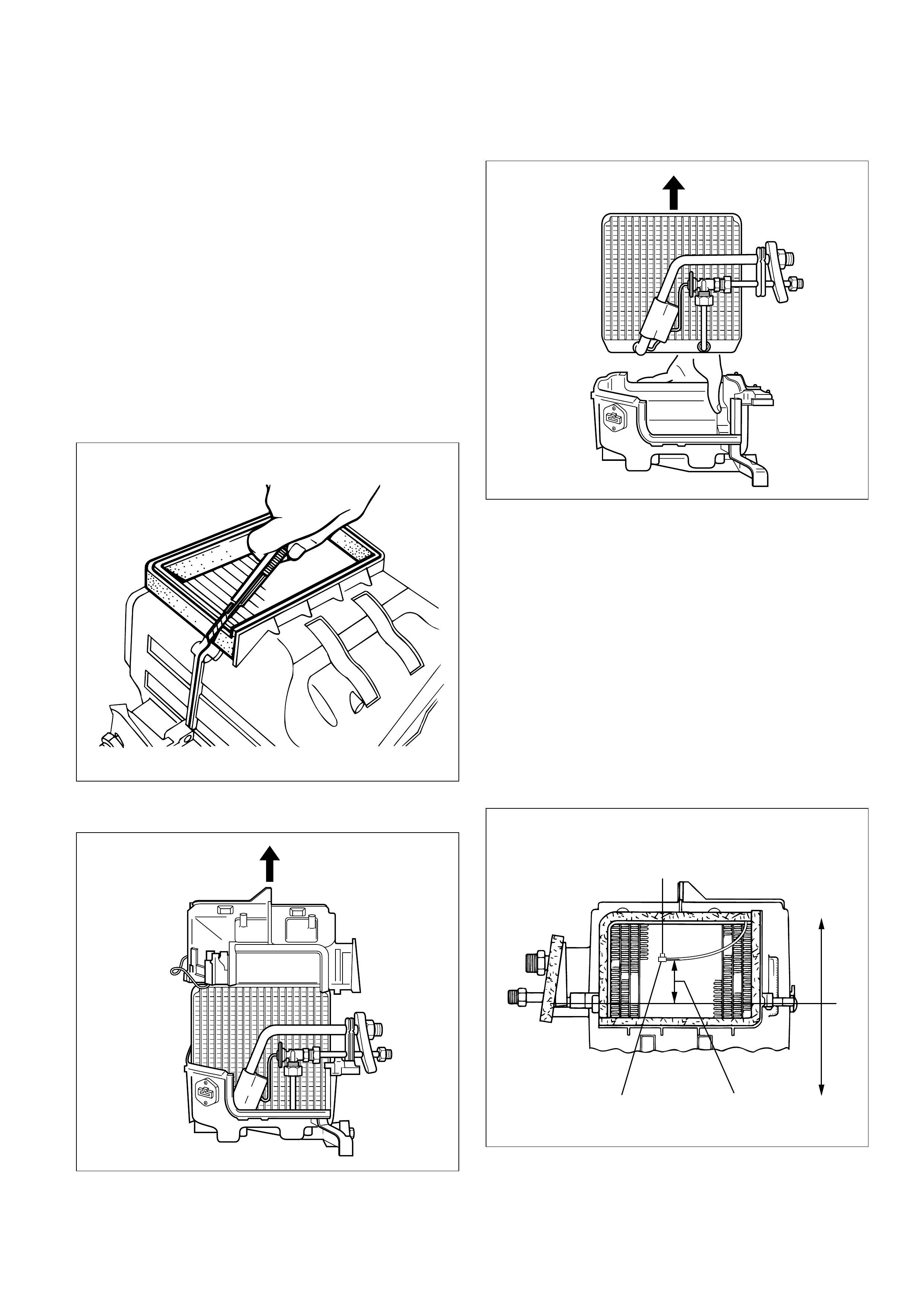
Removal
1. Disconnect the battery ground cable.
2. Discharge and recover refrigerant.
• Refer to Refrigerant Recovery in this section.
3. Remove evaporator assembly.
• Refer to Evaporator Assembly in this section.
4. Remove pollen filter.
5. Pull the sensor from the evaporator assembly.
6. Remove attaching screw.
7. Remove upper case.
8. Remove lower case.
•Slit the case parting face with a knife since the
lining is separated when removing the
evaporator.
•Lift to remove the upper case.
9. Remove evaporator core.
10.Remove expansion valve.
•Tear off the insulator carefully.
•Use a back-up wrench when disconnecting all
refrigerant pipes.
Installation
To install, follow the removal steps in the reverse
order, noting the following points:
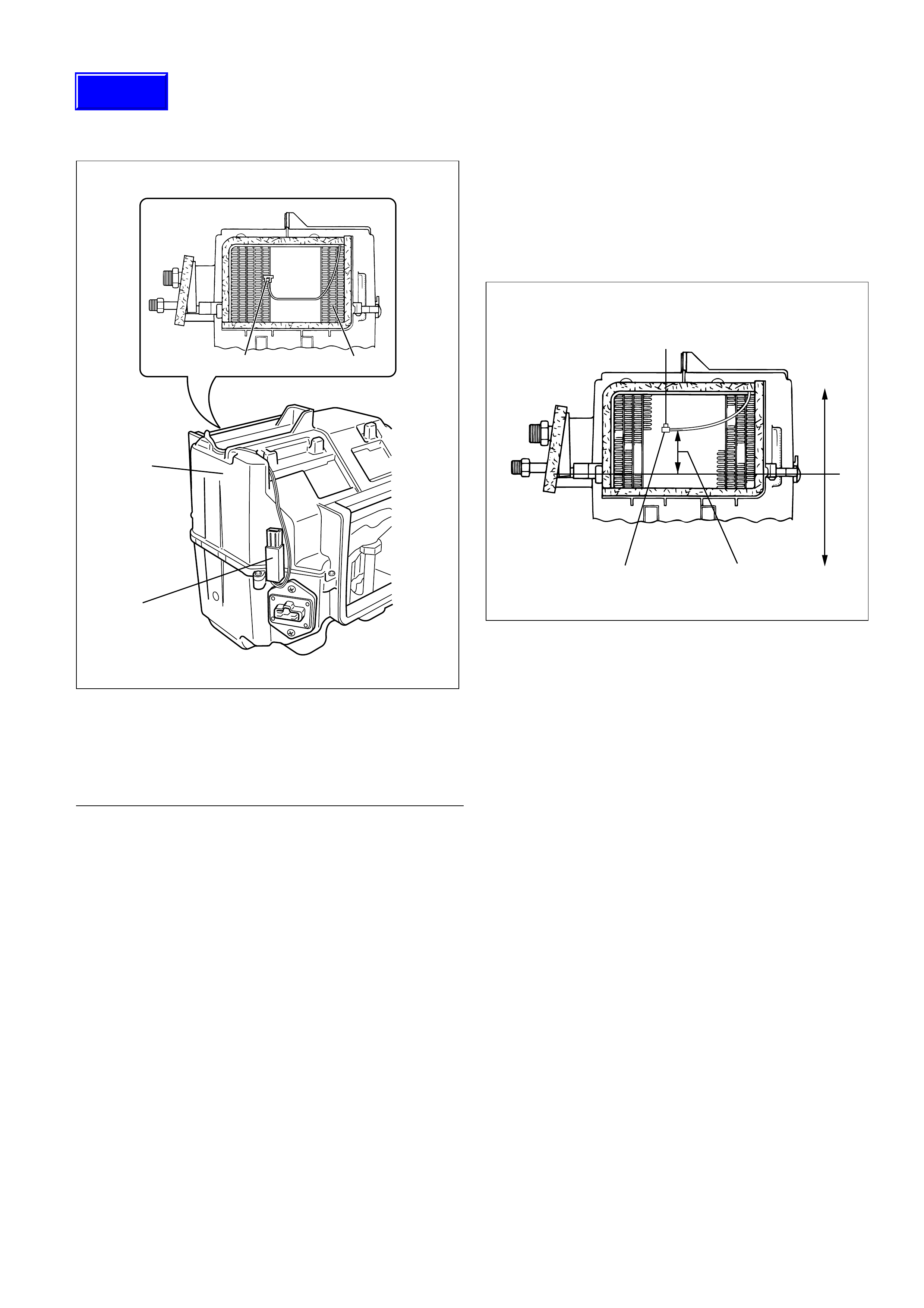
1. The sensor is installed on the core with the clip.
2. The sensor must not interfere with the
evaporator core.
3. When installing the new evaporator core, install
the thermo sensor (2) to the evaporator core (1)
specified position with the clip in the illustration.
874RS006
874RY00005
874RY00006
SENSOR TO BE LOCATED
AT 7TH LINE FROM LEFT
57.5mm(2.26 in.)2
1
Lower case Upper case
874RX021

4. O-rings cannot be reused, Always replace with
new ones.
5. Be sure to apply new compressor oil to the O-
rings when connecting lines.
6. Be sure to install the sensor and the insulator on
the place where they were before.
7. To install a new evaporator core, add 50cc (1.7
fl. oz.) of new compressor oil to the new core.
8. Tighten the refrigerant lines to the specified
torque. Refer to Main Data and Specifications for
Torque Specifications in this section.
9. Apply an adhesive to the parting face of the
lining when assembling the evaporator
assembly.
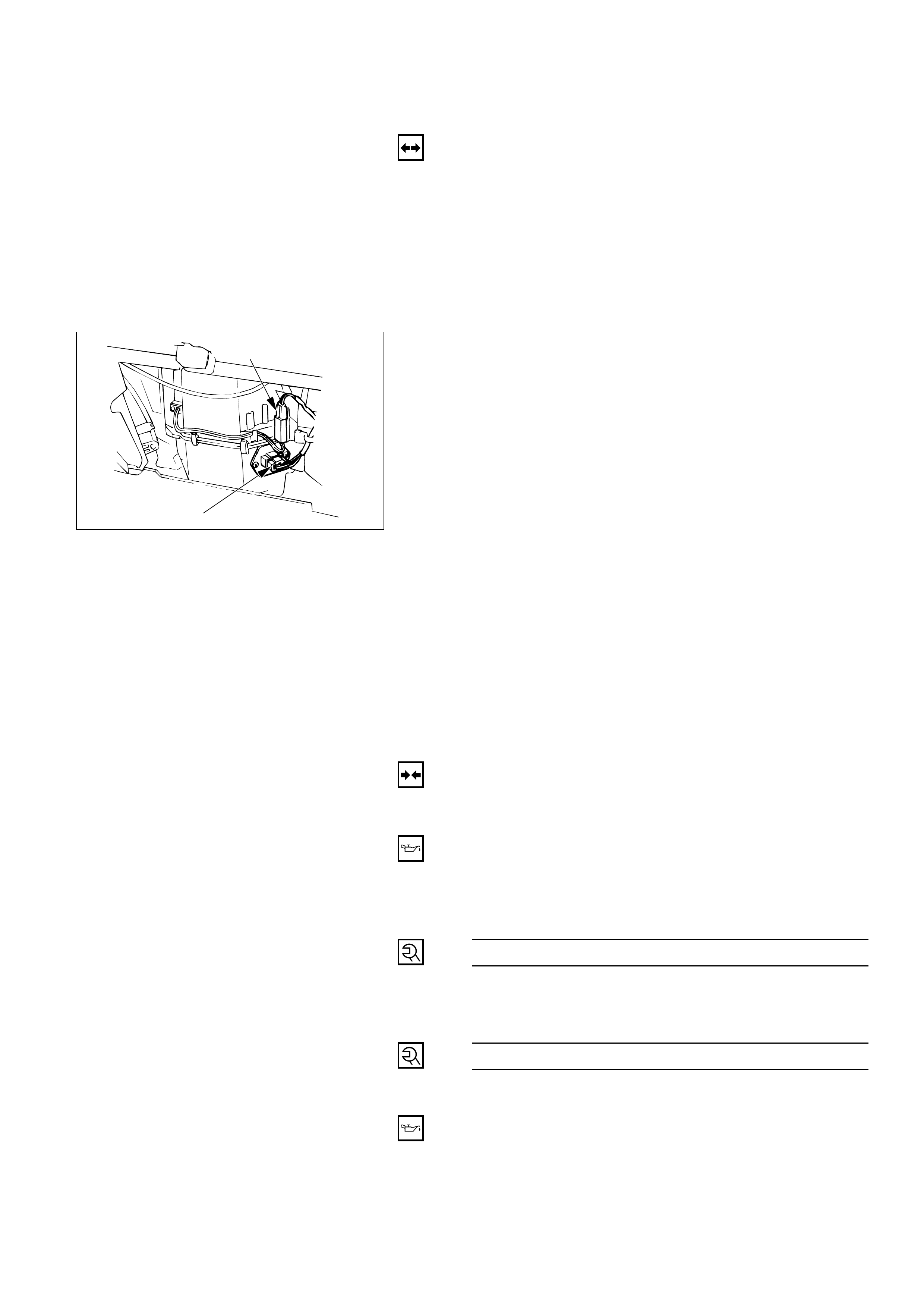
ELECTRONIC THERMOSTAT
Legend
(1) Thermo Sensor(2) Evaporator Core(3) Evaporator(4) Thermostat Unit
Removal1. Disconnect the battery ground cable.
2. Discharge and recover refrigerant.•Refer to Refrigerant Recovery in this section.3. Remove evaporator assembly.
• Refer to Evaporator Assembly removal
procedure in this section.
4. Remove electronic thermostat.
•Pull the sensor from the evaporator assembly.
Installation
To install, follow the removal steps in the reverse
order, noting the following points.
1. Install the thermostat sensor to the evaporator
core specified position with the clip.
2. The sensor is installed on the core with the clip
and it must not interfere with the core.
1 2
3
4
874RX022
SENSOR TO BE LOCATED
AT 7TH LINE FROM LEFT
57.5mm(2.26 in.)2
1
Lower case Upper case
874RX021
Techline
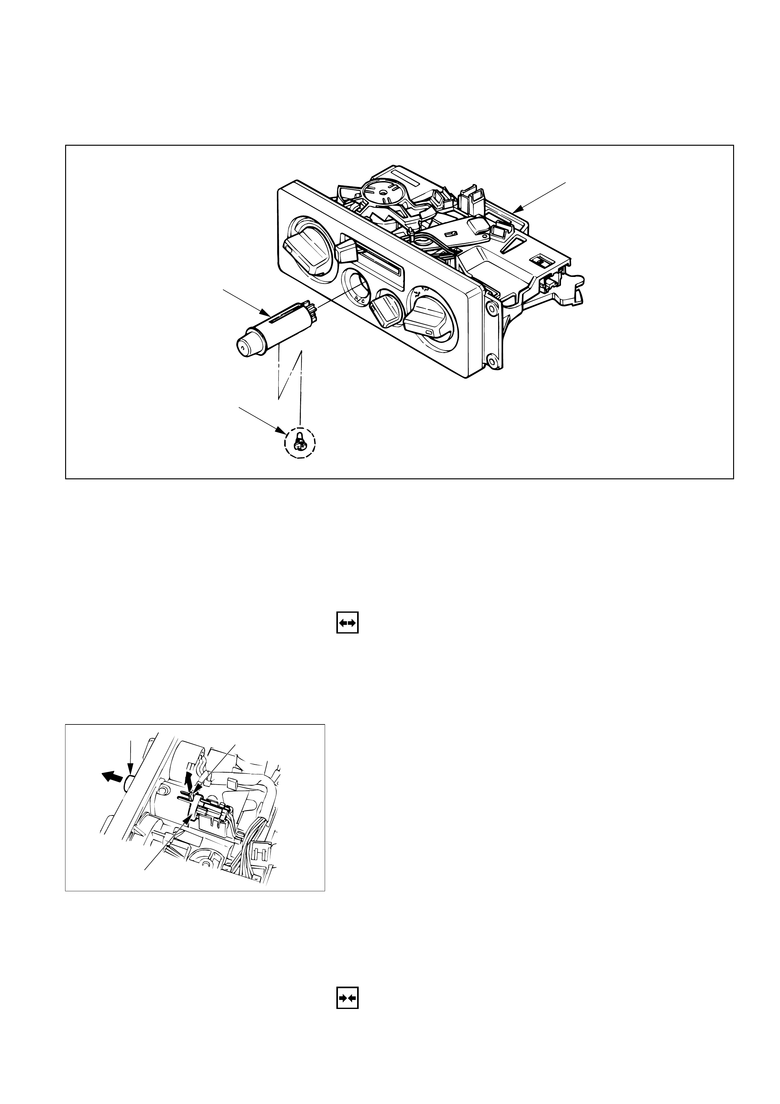
1
2
3
Removal Steps
1. Control lever assembly
2. A/C switch
3. Illumination bulb
Installation Steps
To install, follow the removal steps in the
reverse order.
A/C SWITCH AND ILLUMINATION BULB
REMOVAL
Preparation:
Disconnect the battery ground cable
1. Control Lever Assembly
Refer to Section 2A “CONTROL LEVER ASSEMBLY”
removal procedure.
2. A/C Switch
Raise up the catch portion of the switch and remove
the switch while pushing it toward the outside.
3. Illumination Bulb
Turn the illumination bulb counterclockwise to
remove.
Catch portion
End of switch
A/C switch
INSTALLATION
To install, follow the removal steps in the reverse order.
1
6
7
7
6
5
3
3
3
4
4
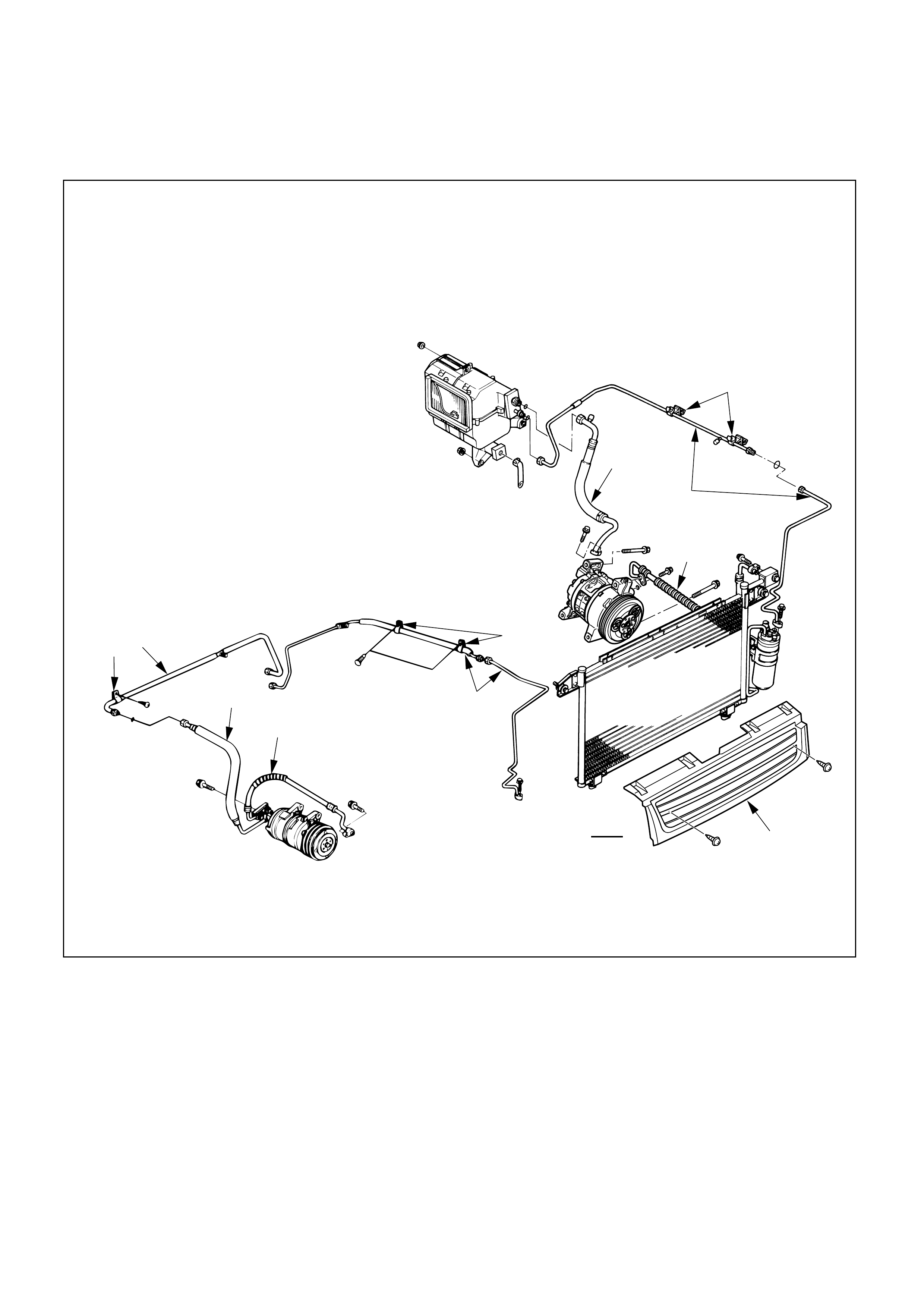
REFRIGERANT LINE
Removal Steps
1. Radiator grille
2. Air cleaner
2a. Dust
2b. Battery and reserver tank
2c. Air cleaner cover
3. Clip and clamp
4. Liquid line (High-pressure pipe)
5. Suction line (Low-pressure pipe)
6. Suction line (Low-pressure hose)
7. Discharge line (High-pressure hose)
Installation Steps
To install, follow the removal steps in the
reverse order.
REMOVAL
Preparation:
• Disconnect the battery ground cable
• Discharge and recover refrigerant (Refer to
“REFRIGERANT RECOVERY” in this section.)
1. Radiator Grille
2. Air Cleaner
2a. Duct
2b. Battery and Reserver Tank
2c. Air Cleaner Cover
3. Clip and Clamp
4. Liquid Line (High-pressure pipe)
5. Suction Line (Low-pressure pipe)
6. Suction Line (Low-pressure hose)
7. Discharge Line (High-pressure hose)
• Use a back-up wrench when disconnecting and
reconnecting the refrigerant lines.
• When removing the refrigerant line connecting
part, the connecting part should immediately be
plugged or capped to prevent foreign matter from
being mixed into the line.
INSTALLATION
To install, follow the removal steps in the reverse order,
noting the following points:
1. O-rings cannot be reused. Always replace new ones.
2. Be sure to apply compressor oil to the O-rings when
connecting refrigerant lines.
3. Tighten the refrigerant line to the specified torque.
(Refer to “SERVICE INFORMATION” for FIXING
TORQUE in section 0A.)
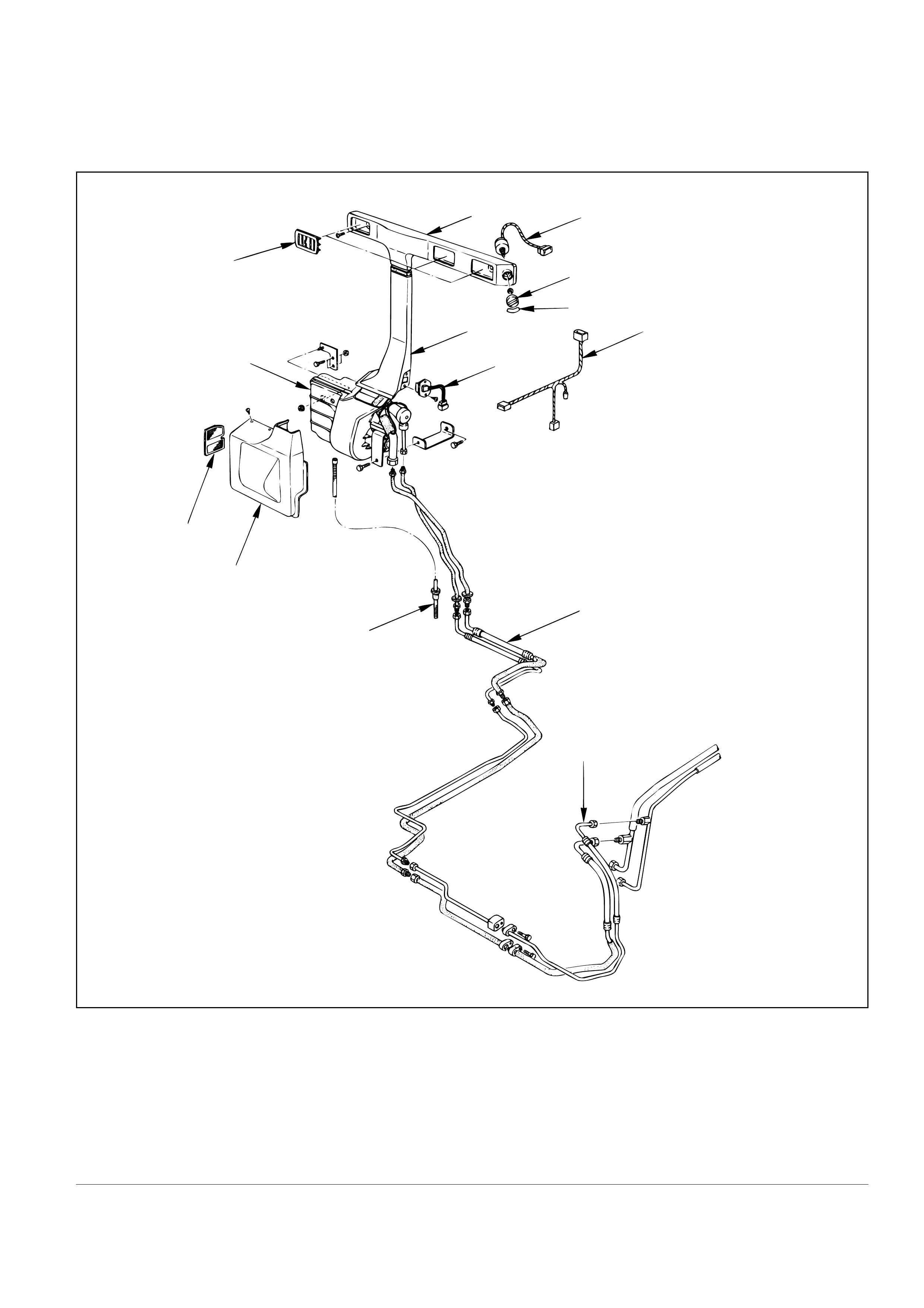
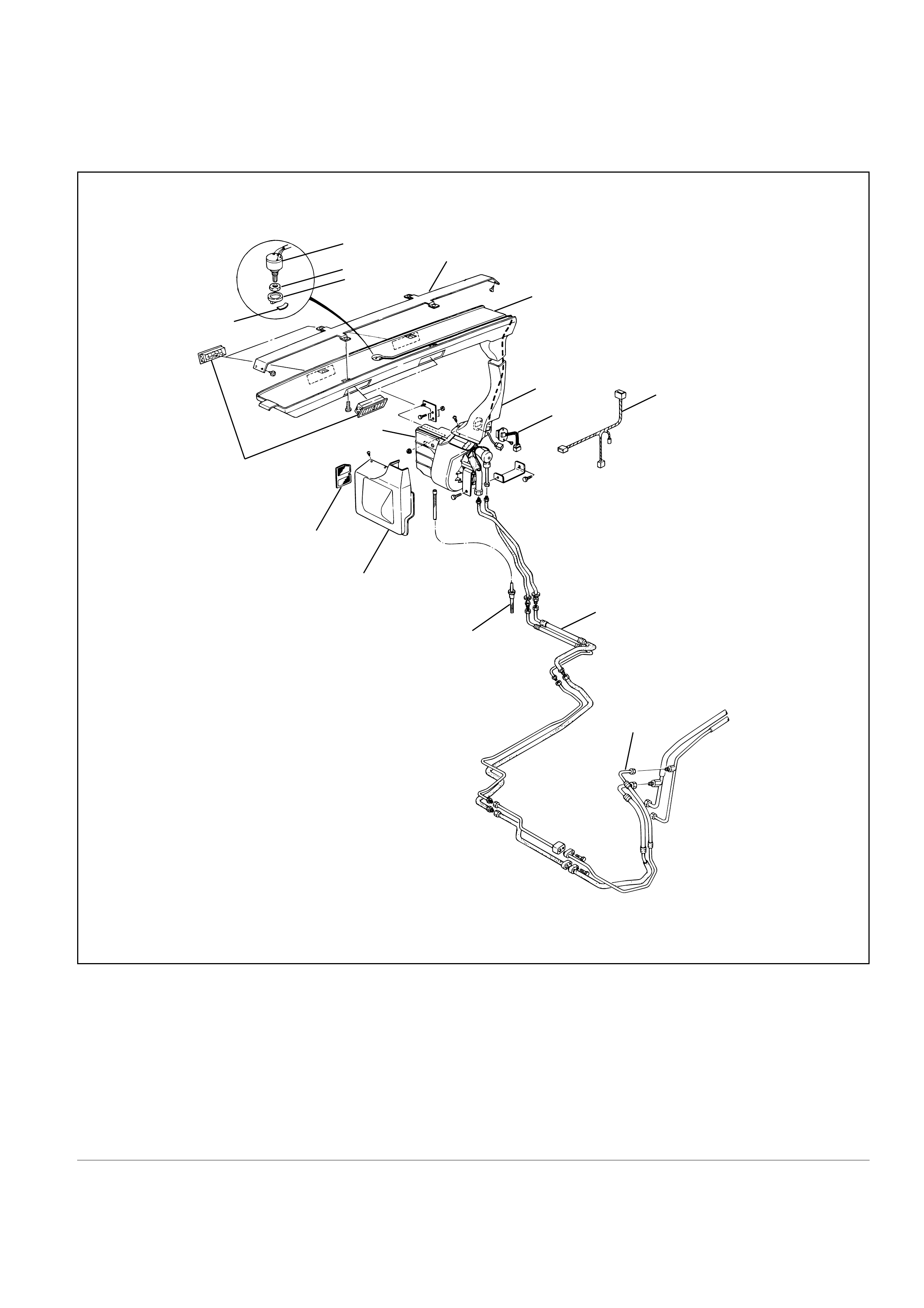
REAR COOLER PARTS
56
7
813
4
9
14
2
12
11
10
3
1
Legend
(1) Liquid Line (high pressure pipe)
(2) Cooling Unit
(3) Suction Line (low pressure pipe)
(4) Duct Assembly
(5) Duct Assembly
(6) Switch
(7) Knob
(8) Panel
(9) Resistor
(10) Drain Hose
(11) Cover Assembly
(12) Filter
(13) Wire Harness
(14) Grille Assembly
855RY00002
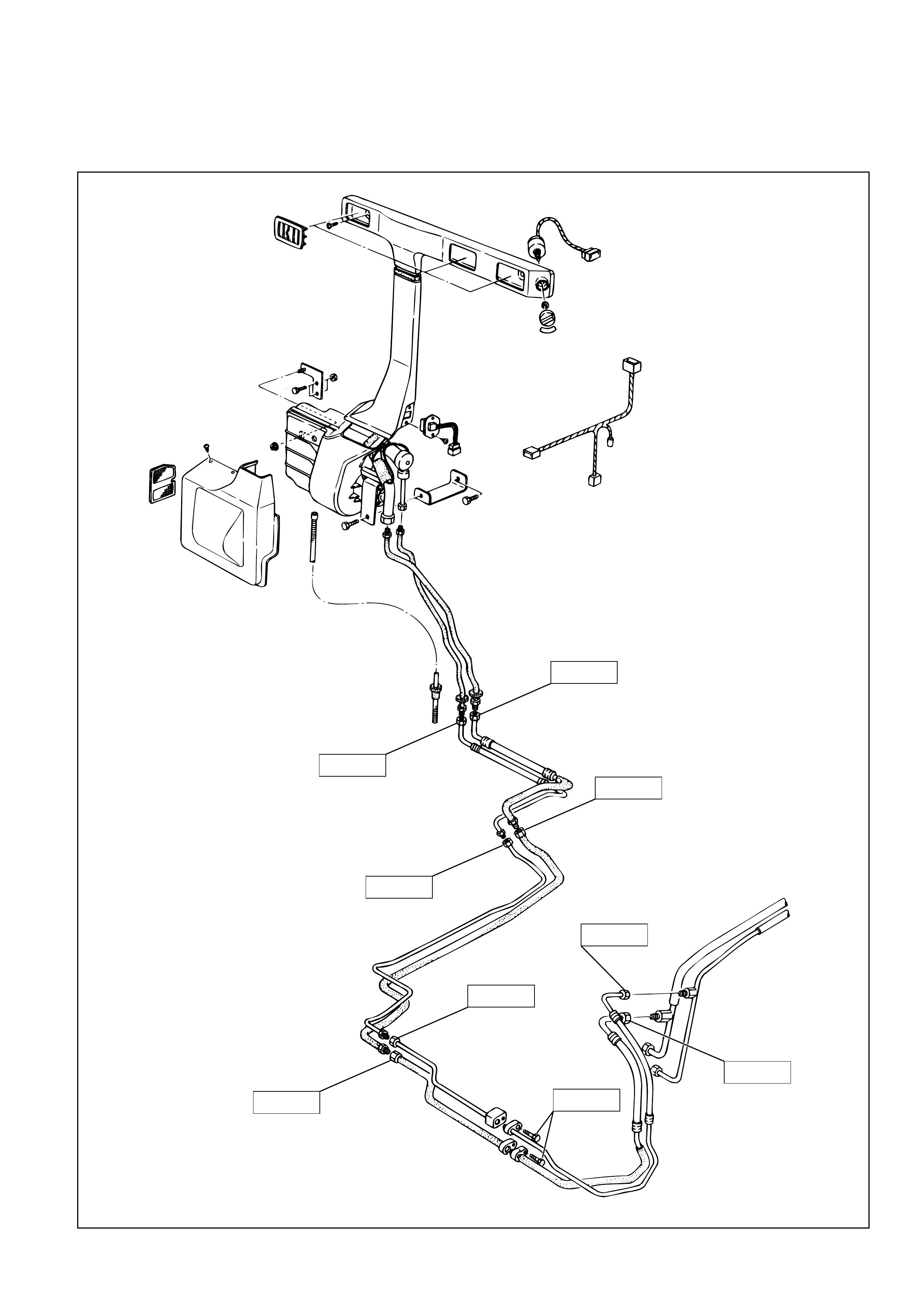
REAR COOLER PARTS (ROOF DUCT TYPE)
16
15
14 2
3
45
7
6
1
13
11
12
10
9
8
Legend
(1) Roof Duct Bracket
(2) Roof Duct
(3) Lower Duct
(4) Resistor
(5) Wire Harness
(6) Liquid Line (high pressure pipe)
(7) Suction Line (low pressure pipe)
(8) Drain Hose
(9) Cover Assembly
(10) Filter
(11) Cooling Unit
(12) Grille Assembly
(13) Panel
(14) Knob
(15) Nut
(16) Fan Control Switch
855RY00001
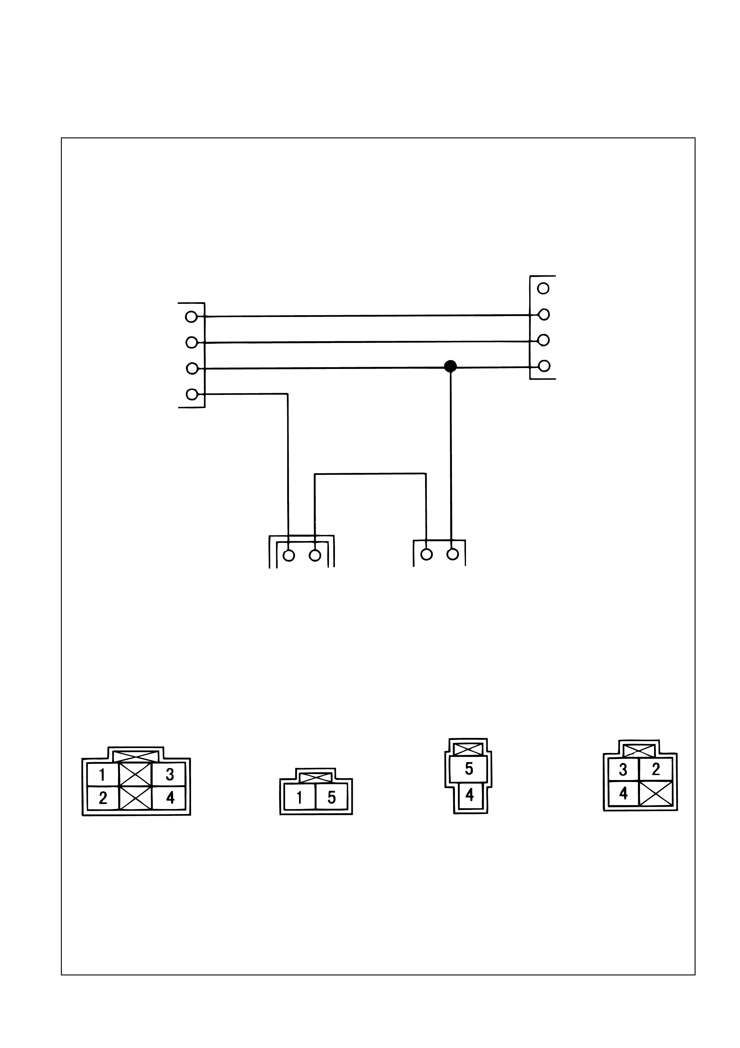
Switch Vehicle Motor Resistor
15 54
(Vehicle) (Motor)
0.85 RW
0.85 B
0.85 RB
(Resistor)(Switch)
0.5 LG
0.85 RG
0.85 WR
2
3
4
1
2 LO
3 MI
4 HI
WIRING DIAGRAM
D08RY00303
E06RY00003
25(2.5/18)
25(2.5/18)
25(2.5/18)
25(2.5/18)
15(1.5/11)
15(1.5/11)
15(1.5/11)
15(1.5/11)
15(1.5/11)
TORQUE SPECIFICATIONS N·m (kg·m/ib·ft)
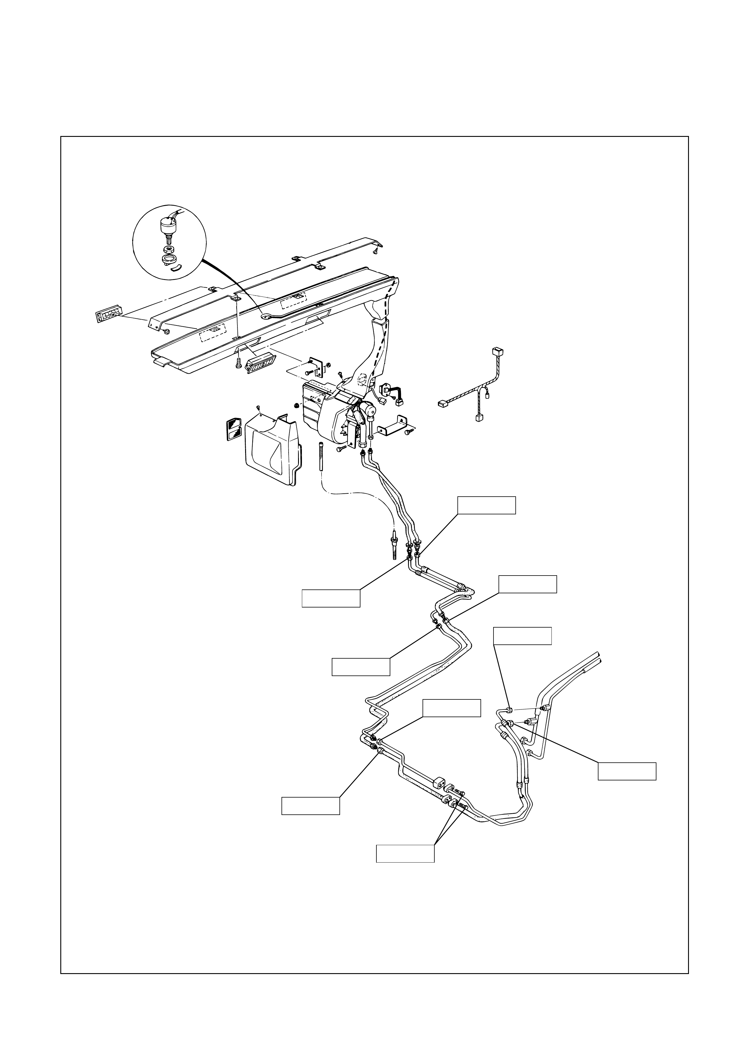
25 (2.5/18)
25 (2.5/18)
25 (2.5/18)
25 (2.5/18)
15 (1.5/11)
15 (1.5/11)
15 (1.5/11)
15 (1.5/11)
15 (1.5/11)
TORQUE SPECIFICATIONS (ROOF DUCT TYPE) N·m (kg·m/ib·ft)
E06RY00002

DIAGNOSIS
Rear Air Conditioning Cycle Diagnosis
Condition Possible Cause Correction
No cooling or insufficient cooling
Insufficient velocity of cooling air
Front air conditioner not switched
on.
Other
Clogged filter
Other
Switch front A/C switch ON.
See front air conditioner
workshop manual.
Clean or replace cooling unit filter.
See front air conditioner
workshop manual.
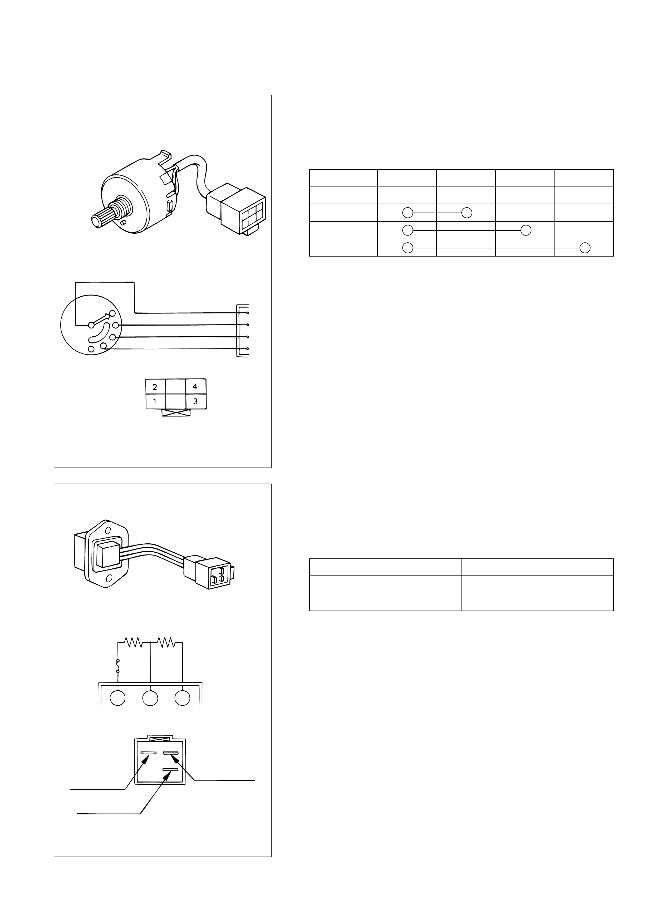
FAN CONTROL SWITCH
Inspection
Using an electric circuit tester, check continuity between
terminals.
If not as specified, replace the switch.
1234
OFF
LOW
MEDIUM
HIGH
Fan control switch
OFF
L 0.5 LG
0.85 Y
0.85 RG
0.85 B
M
H
1
2
3
4
Resistor
0.5Ω1.1Ω
Mo MH ML
0.5 LG(ML)
0.85 WR(Mo)
0.85 RG(MH)
RESISTOR
Inspection
Using an electric circuit tester, check the resistance
between the terminals specified below.
If the resistances are not as specified, replace the resistor.
Terminal Resistance (Ω)
Mo ~ MH 0.5
Mo ~ ML 1.6
825RY00058
826RY00016
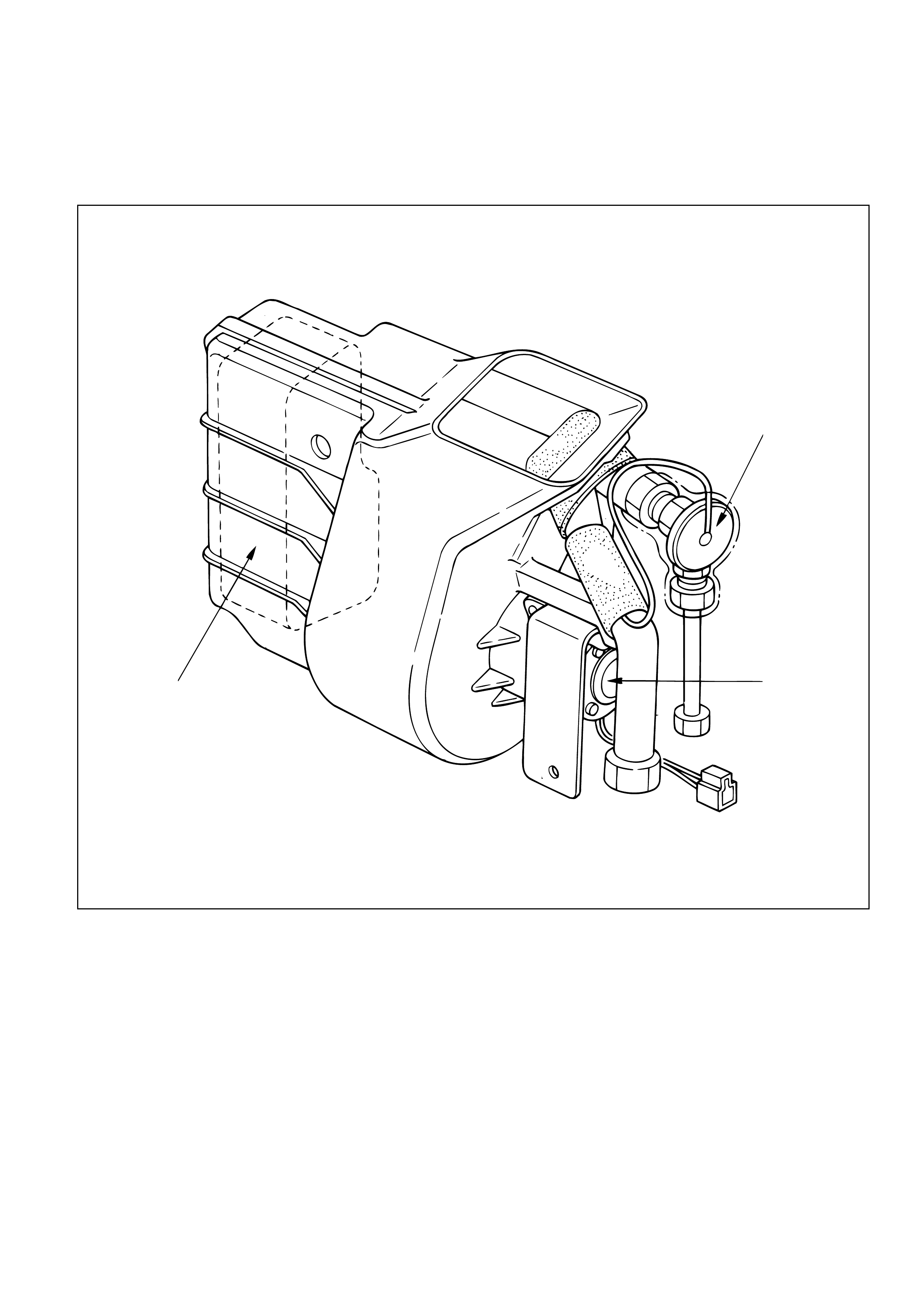
COOLING UNIT
Main Components
2
3
1
Legend
(1) Evaporator Assembly
(2) Expansion Valve
(3) Fan Motor
872RY00001
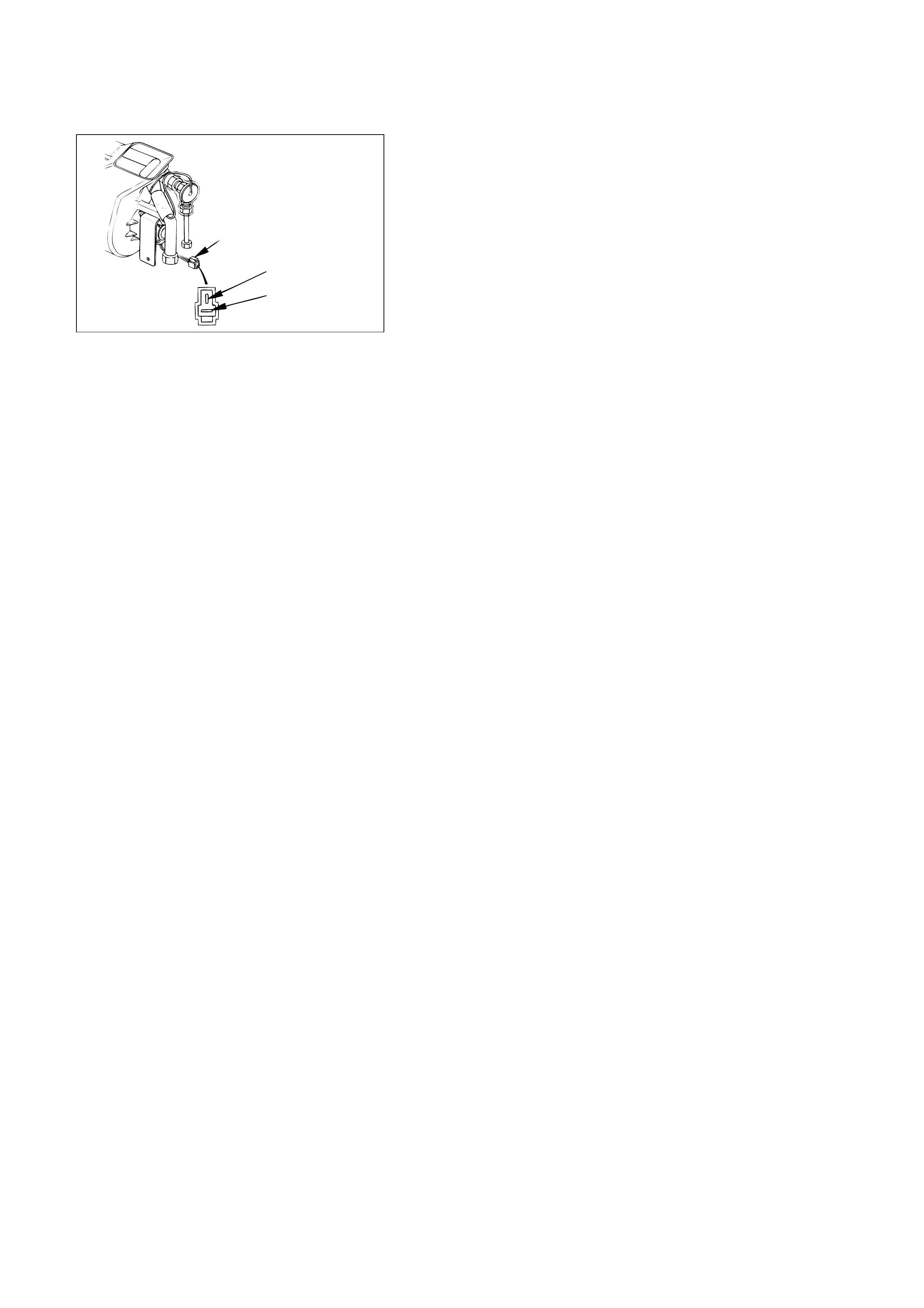
FAN MOTOR
Inspection
1. Disconnect the fan motor connector from the A/C
harness.
2. Connect the battery’s positive terminal to the No.5
terminal of the fan motor and the negative terminal to
the No.4 terminal.
3. Check that the fan motor operates correctly.
Fan motor connector
0.85 B (-) 4
0.85 R (+) 5
872RY00002