
CAUTION
When fasteners are removed, always
reinstall them at the same location from
which they were removed. If a fastener
needs to be replaced, use the correct part
number fastener for that application. If the
correct part number fastener is not available,
a fastener of equal size and strength (or
stronger) may be used.
Fasteners that are not reused, and those
requiring thread locking compound, will be
called out. The correct torque values must
be used when installing fasteners that
require it. If the above conditions are not
followed, parts or system damage could
result.
SECTION 2C - HVAC AUTO AIR CONDITIONING
Full Automatic Air Conditioning System
General Description
Full Automatic Air Conditioner Part Configuration
Circuit Diagram
Function and Features
Full Automatic Air Conditioner Block Diagram
Air Conditioning Parts
Control Panel Layout
Air Control Functions
Operation and Function of Control Panel Switches
Overview of Construction, Movement and Control of Major Parts of Full Automatic
Air Conditioner System
Overview of Automatic Control of Full Automatic Air Conditioner
Troubleshooting
Troubleshooting, Its Overview and Procedures
Performance and Movement Checklist for Automatic Air Conditioner Related
Parts
Troubleshooting with Self-Diagnosis Function
Inspection by Failed Location
Inspection of the Sensors
Inspection of the Intake Actuator System
Inspection of the Mix Actuator System
Inspection of the Mode Actuator System
Inspection of the Fan Motor System
Inspection of the Magnet Clutch System
Inspection of the Air Conditioner Room Temperature Setup System
Individual Inspection
Sun Sensor..........................................................1B–128
Electronic Thermostat.................................................1B–128
Mode Actuator.......................................................1B–129
Mix Actuator.........................................................1B–129
Intake Actuator ......................................................1B–130
Techline

1
13
10
97
6
5
8
11
12
2
4
3
FULL AUTOMATIC AIR CONDITIONING SYSTEM
GENERAL DESCRIPTION
Using a variety of sensors, this full automatic heater and air conditioner accurately senses outside air
temperature, solar radiation quantity, evaporator’s blowing temperature, heater core coolant temperature
and interior temperature, then enters these data to the automatic heater/air conditioner control unit
(equipped with the built-in micro-computer). The data provided to the control unit enables to automatically
control blow temperature and blow air quantity, turn on or off the compressor and switch the blow port as
well as switching between the fresh air intake and interior air circulation.
Resetting the automatic function allows you to switch to the manual control mode.
The self-diagnosis function of the automatic heater and air conditioner control unit (with the built-in micro-
computer) allows the unit to access and diagnose a failed part easier and quicker.
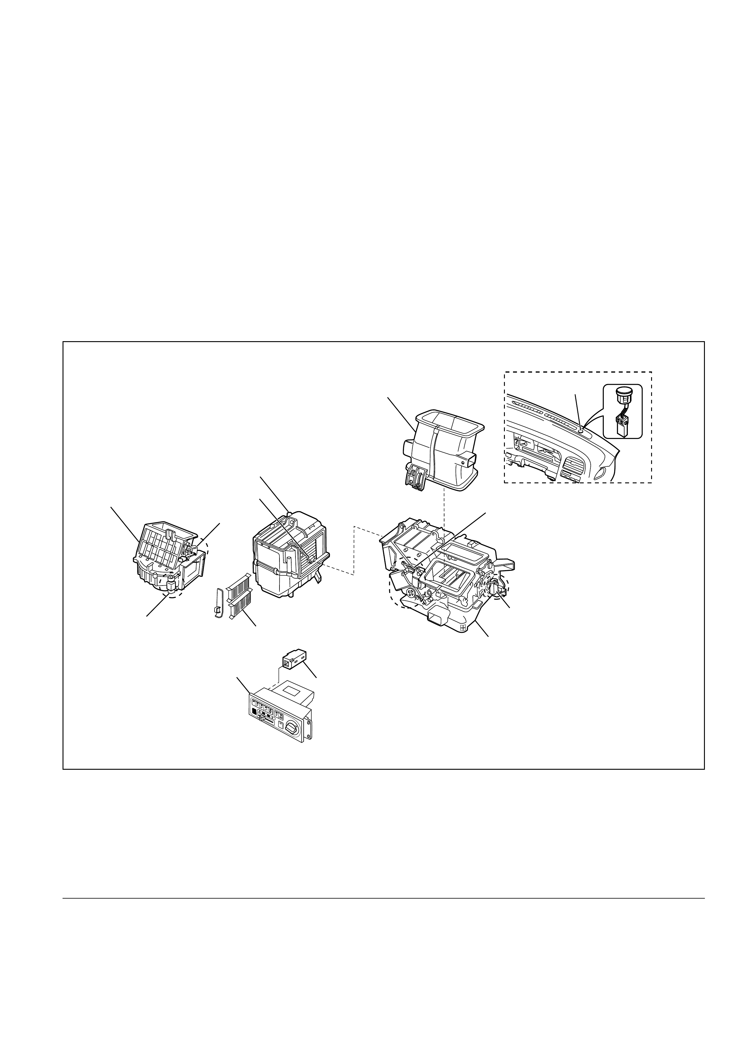
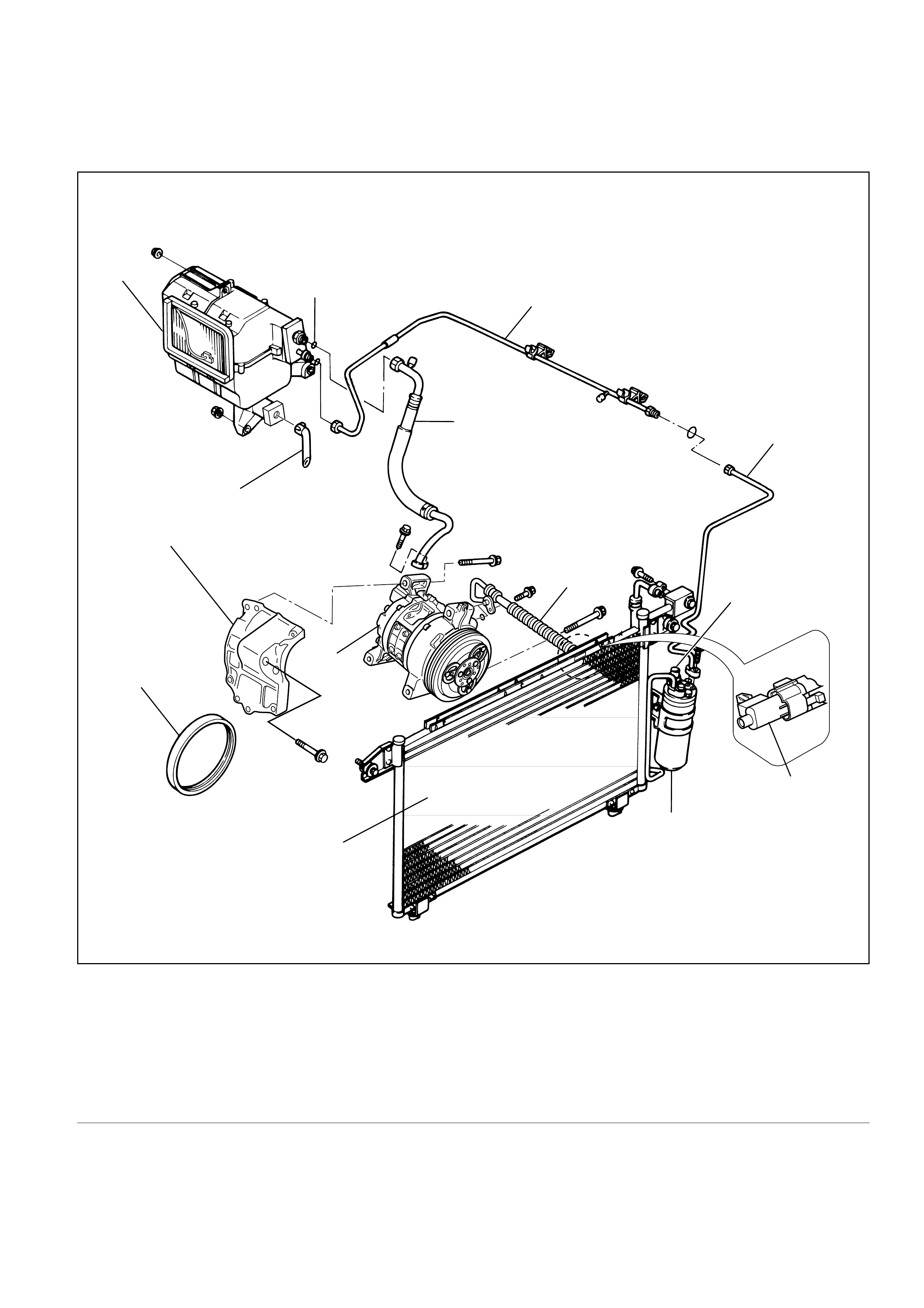
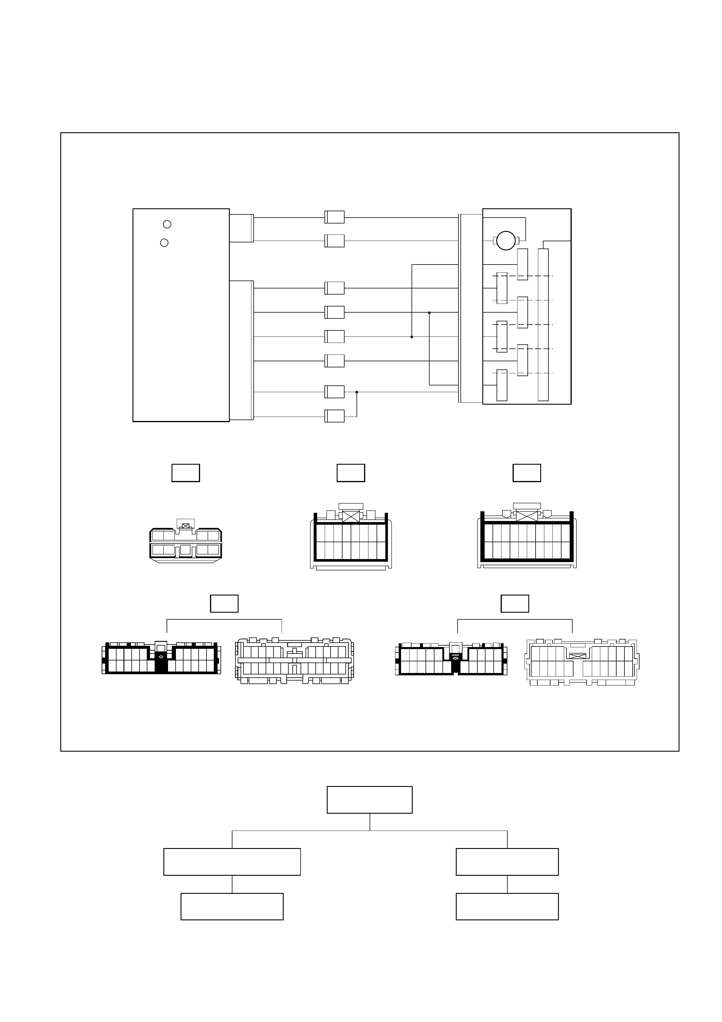
Full Automatic Air Conditioner Parts Configuration
865RY0004
Legend
(1) Lower Center Vent Box
(2) Sun Sensor
(3) Mix Actuator
(4) Mode Actuator
(5) Heater Unit
(6) In Car Sensor
(7) Pollen Filter
(8) Automatic Air Conditioner Control Unit
(9) Max-High Relay
(10) Blower Unit
(11) Intake Actuator
(12) Duct Sensor
(13) Evaporator Assembly
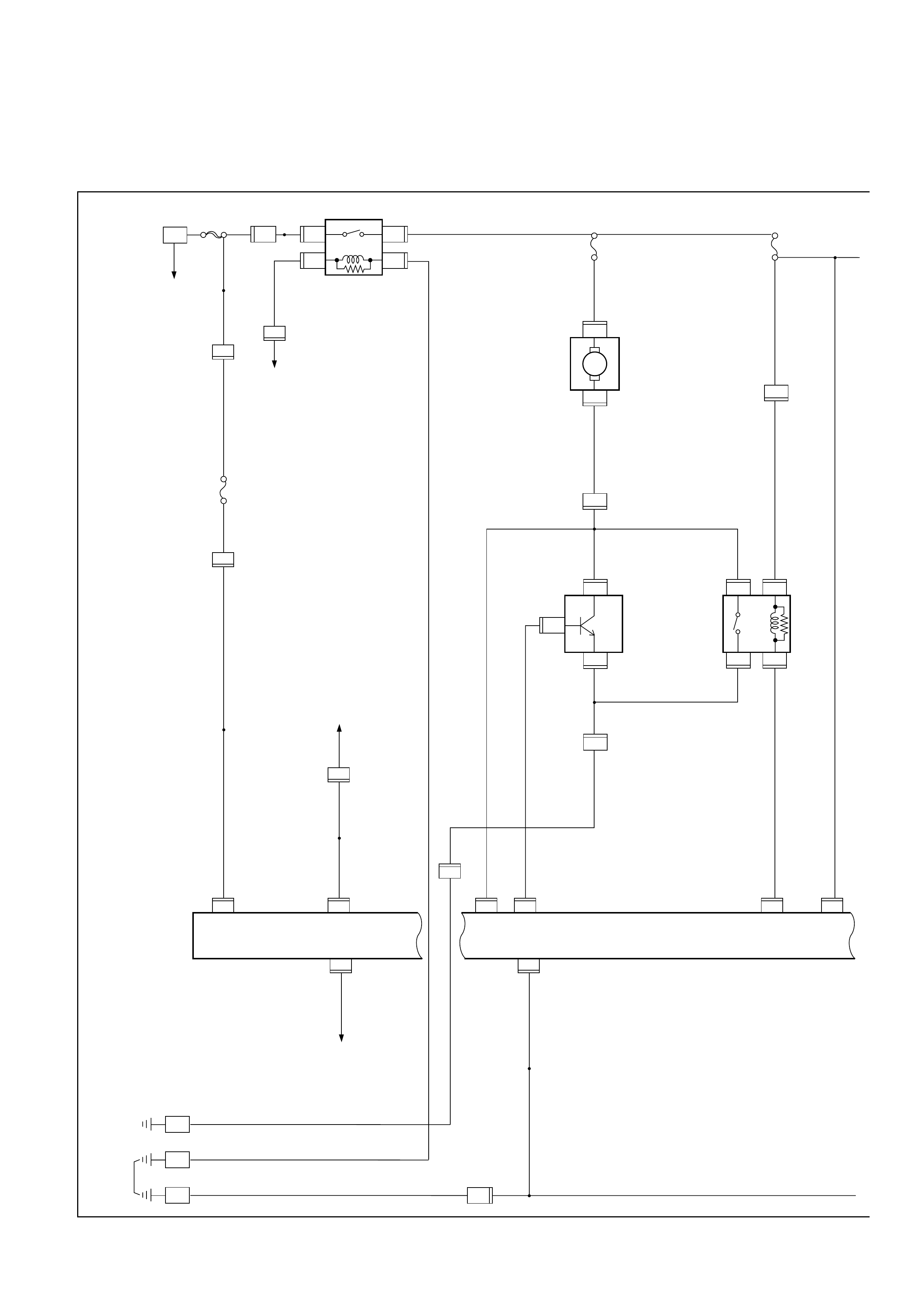
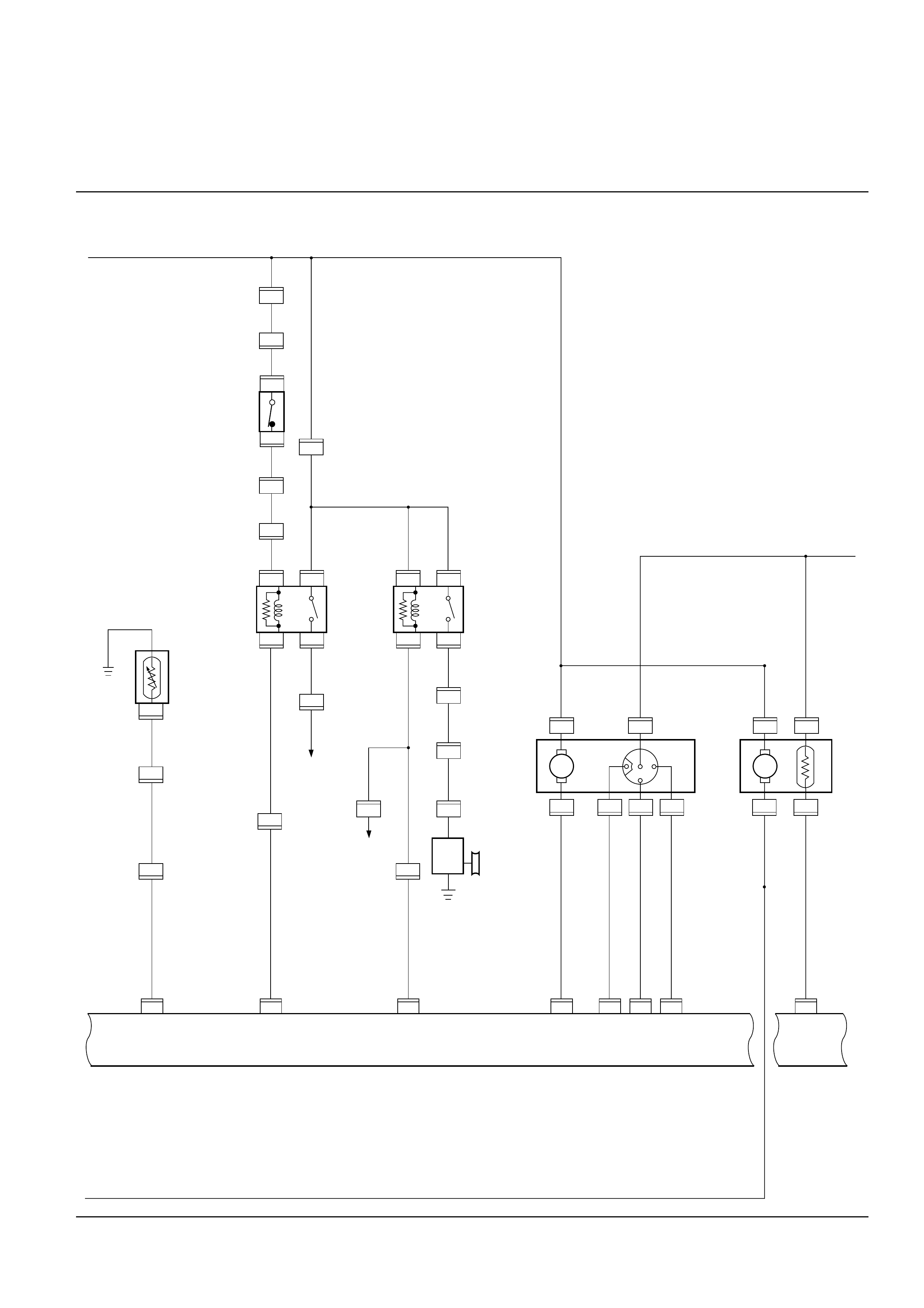
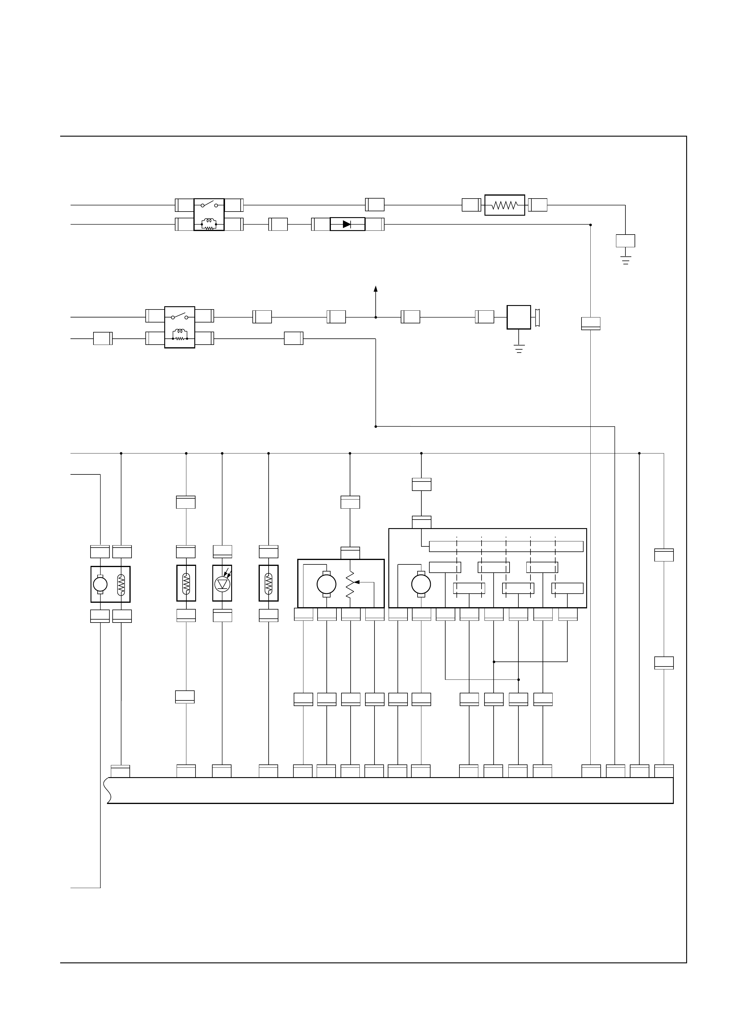
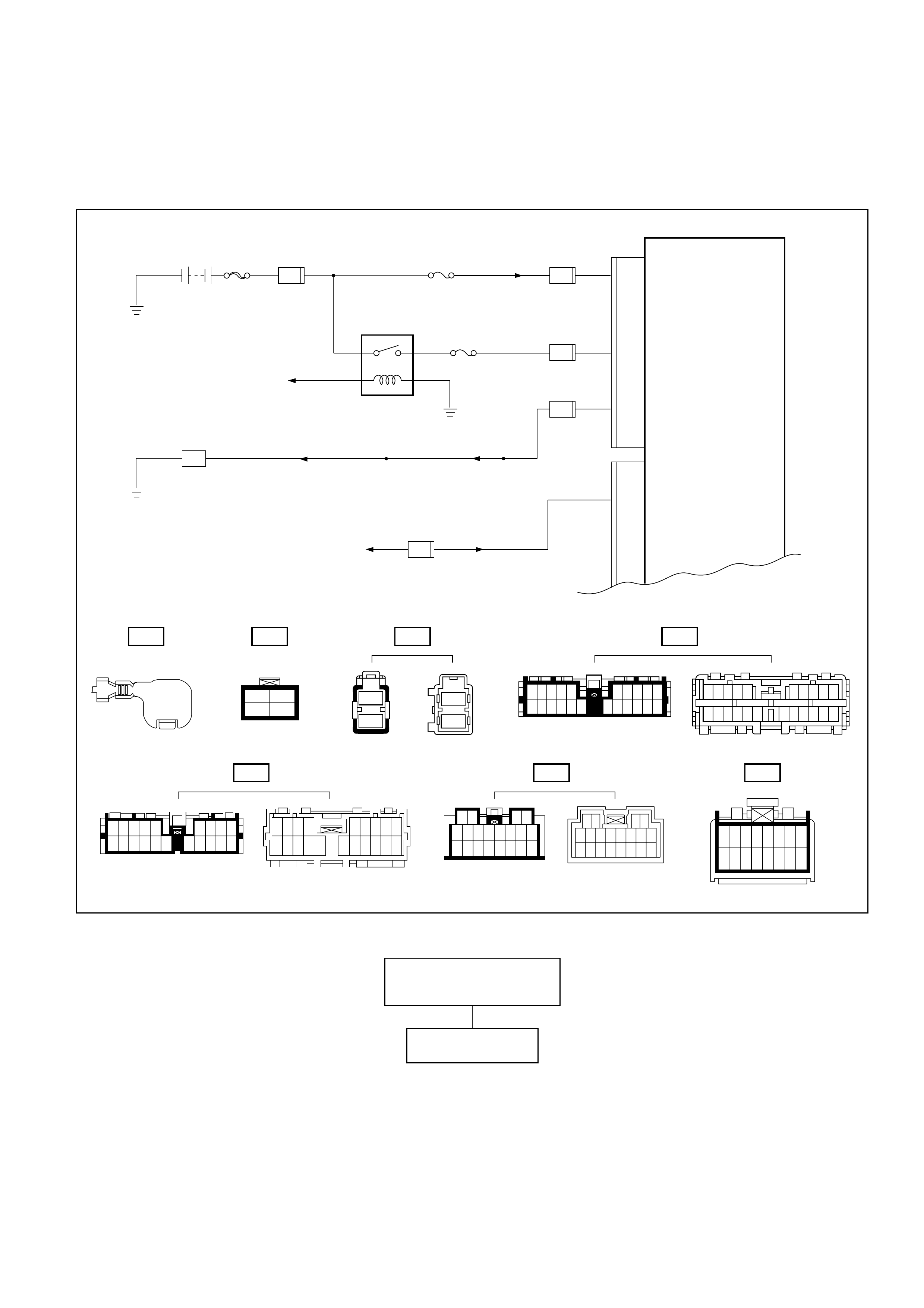
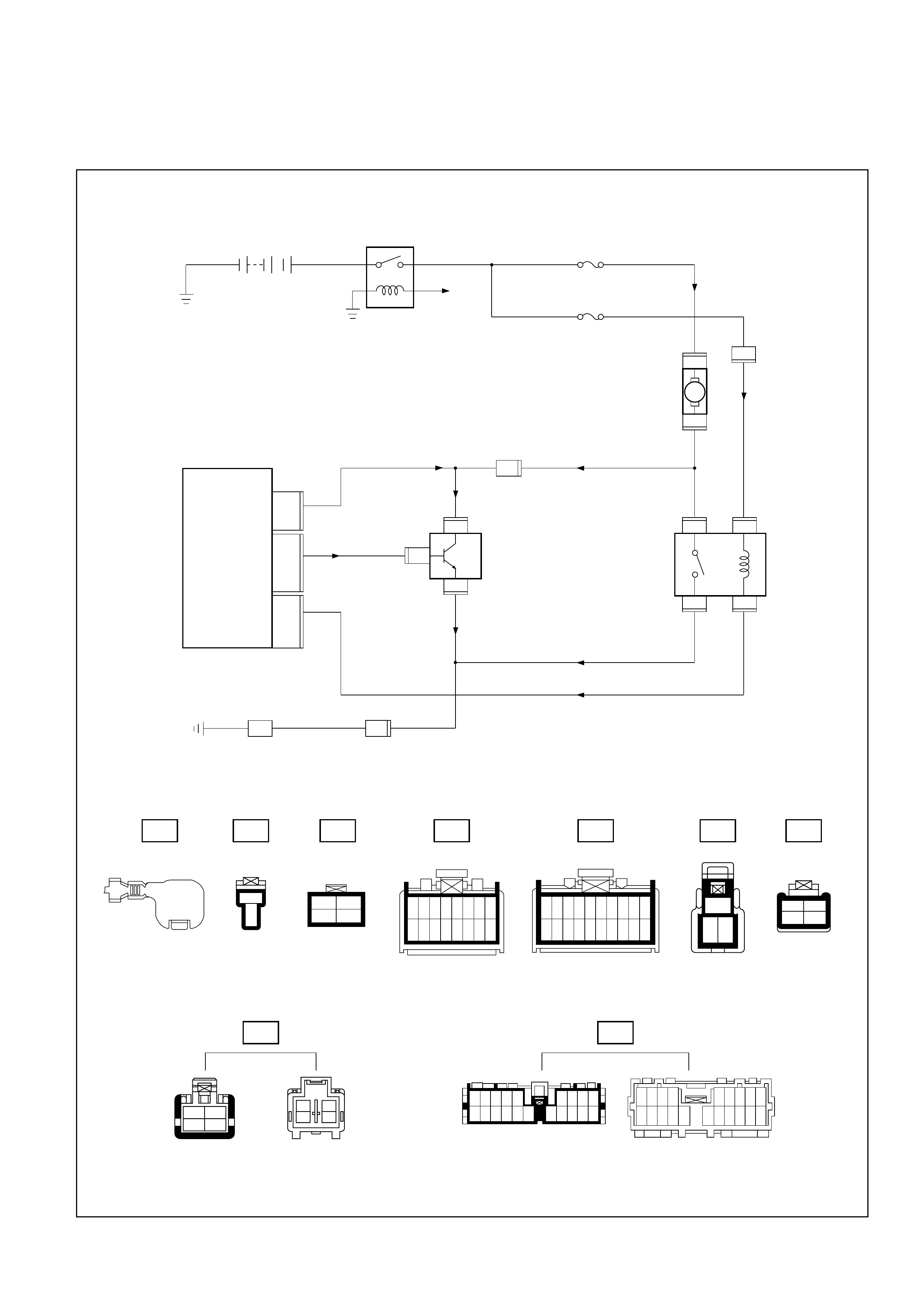
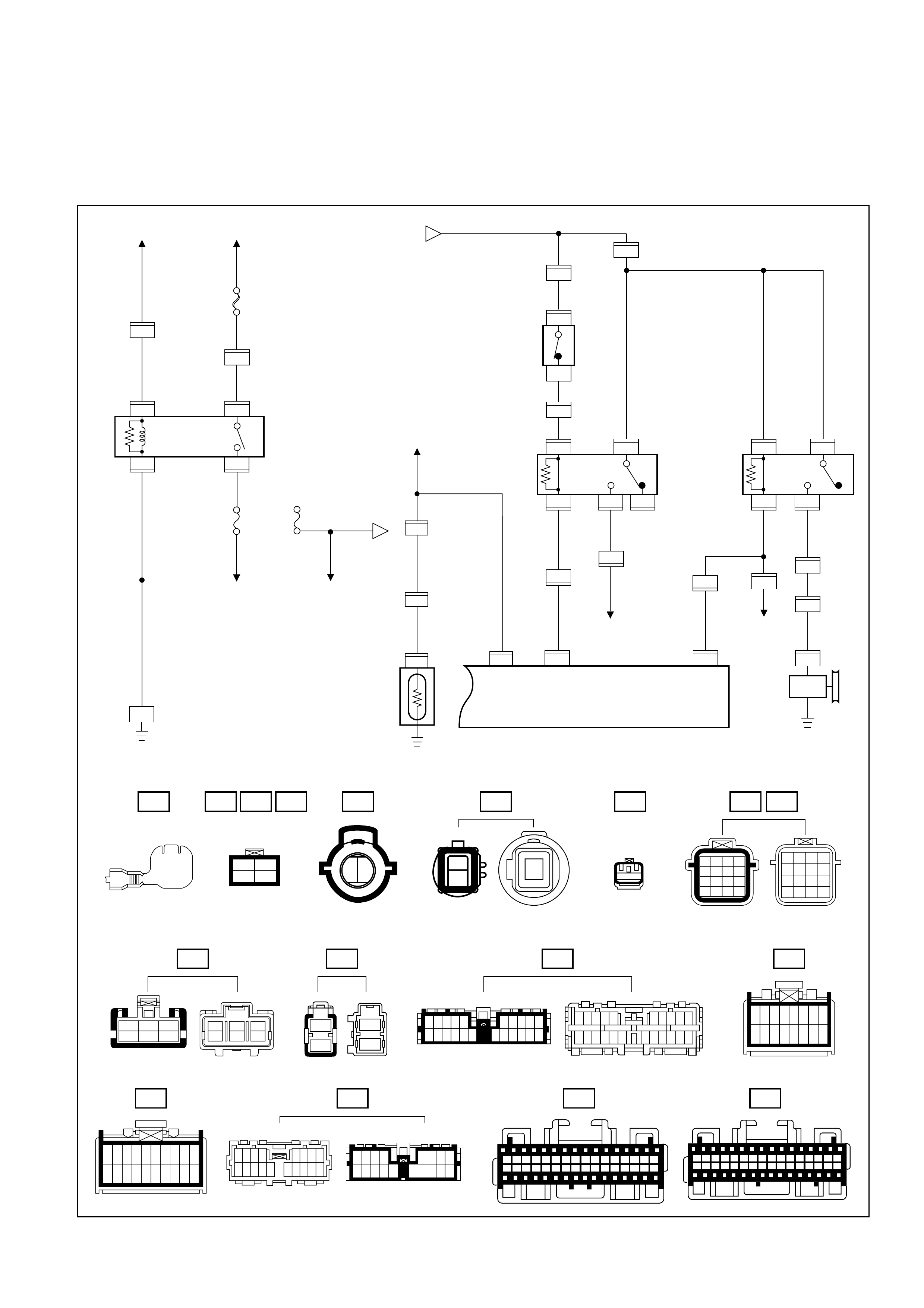
CIRCUIT DIAGRAM
6VE1
B-5
BLOWER
MOTOR
2
B-5
1
I-51
3
I-51
I-51I-51
MAX HI
RELAY
POWER
TRANSISTOR
I-50
I-50
4
H-20
2
H-26
10
1
3
H-20
1
21
2L/B
0.5P/G
12
I-32
16
I-32
P-2
0.85W/G
5W
5W0.5R/W
0.3B
0.5R/W0.3R/W
TAIL RELAY(4)
ILLUMINATION
CONTROLLER 0.5G/R 0.85G/R
1.25B
1.25B 1.25B
0.5B
9
I-32
5W 3W
BATT
FL-1
80A
MAIN 4
B-36
3
3L/R C-19 25A
BLOWER C-20 10A
AIR CON
3L2L/B
0.3BR
0.5BR
0.3BR
2/B
0.3GR
0.3GR/L
0.5L/B
2/B
B-36
20
H-27
2
B-36H-14 1
B-36
HEATER & A/C RELAY
STARTER RELAY(1)
H-14
1H-13
10
I-32
8
H-26
9
10
C-16
10A CLOCK ROOM
BODY-RH
BODY-LH
B-18
B-19
B-1
AUTO A/C CONTROL UNIT AUTO A/C CONTROL UNIT
I-32
17
143521 12 33
7
I-32
22
296
I-33
1
H-20
14
H-16
M
19
2B
I-33
2
I-50
D08RY00118
E-19
A/C TEHRMO
RELAY
THERMO
UNIT
PRESSURE
SW
I-32
14
I-33
4
I-33
18
I-32
11
AUTO A/C CONTROL UNIT
H-16
16
H-241
H-611
H-16
17
H-416
0.5P/G
0.5Y/B 0.5Y/B
0.5P/G
0.5G/O
1.25B
0.5G/O
0.5G/B
0.5G/B
0.5BR/Y0.5BR/Y 0.5BR/Y
0.3G/B
0.5L/O
0.5L/W
0.3L/R
0.3L/Y
0.3BR/B
0.5B1.25B
0.5G/B
0.5G/W0.5G/W 0.5G/W 0.5BR0.5LG0.5BR
0.5BR 0.5RB
0.5BR
0.5BR
0.5BR
0.5BR
0.3B/L
0.3B/L
PCM(E15)
PCM(B14)
X - 5
4
X - 5
1
X -5
3
12
H-16
7
H-24
13
X - 5
2
A/C COMPRESSOR
RELAY
MAGNETIC
CLUTCH
INTAKE
ACTUATOR
X - 7
4
X -7
3
X -7
1
X - 7
2
H-41
7
H-6
9
E-3
1
1
2
C-25
C-25
H-41
1
H-51
4
H-51
I-49
3
I-49
4612
MINCAR
SENSOR
I-34
1
I-34
4
M
I-49
5
I-49 I-49 I-49
2
I-34
3
I-34
I-33
12
I-33
13
I-33
1
I-33
14
101718193413317
H-41
5
D08RY00293

3
C
H
I-45
M
C-86
2
H-24
9
1
C-86 6
I-45
8
H-24
2
9 11 8 23 24 16 6 25 26 1 2 3 4
I-33
0.3LG/B 0.3LG/B 0.3B/L
0.3B/L
AMBIENT SENSOR
3
I-33 6
I-32
0.3V/W
0.3LG/W
0.3V/W
0.3B/L
0.3B/L
0.3B/L 0.3B/L
0.3B/L
SUN SENSOR
MIX ACTUATOR
I-40
2
I-35
2
H-67
8
1
I-40 1
I-35
4
H-67
8
I-45
5
I-32
0.3V/R 0.3V/R
5
H-67
2
I-45 7
I-45
15
I-33
0.3V/G 0.3V/G 0.3B/L 0.3B/L
6
H-67
5
I-33
0.3V 0.3V
7
H-67
20
I-33
0.3LG/W
DUCT SENSOR
9
VENT B/L FOOT D/F DEF
B-69
4
H-26
M
1
B-69
4
I-32
0.3Y/BR0.3Y/BR
0.3Y/G
0.3GR/G
0.3GR
0.3GR/R
0.3Y/G
0.3GR
0.3GR/R
0.3GR/G0.3GR/G
0.3B/L 0.3B/L
0.3GR/L0.3GR/L
0.3GR/R
5
B-69
3
I-32
4
B-69 3
B-69
10
I-33
8
B-69
9
I-33
7
B-69
8
I-33
2
11 12 18 19 5 1
B-69 6
B-69
H-25 H-25 H-26 H-26 H-25 H-26
8
H-25
7
I-33 11
I-33
6
I-33
MODE ACTUATOR
AUTO A/C CONTROL UNIT
D08RY00120
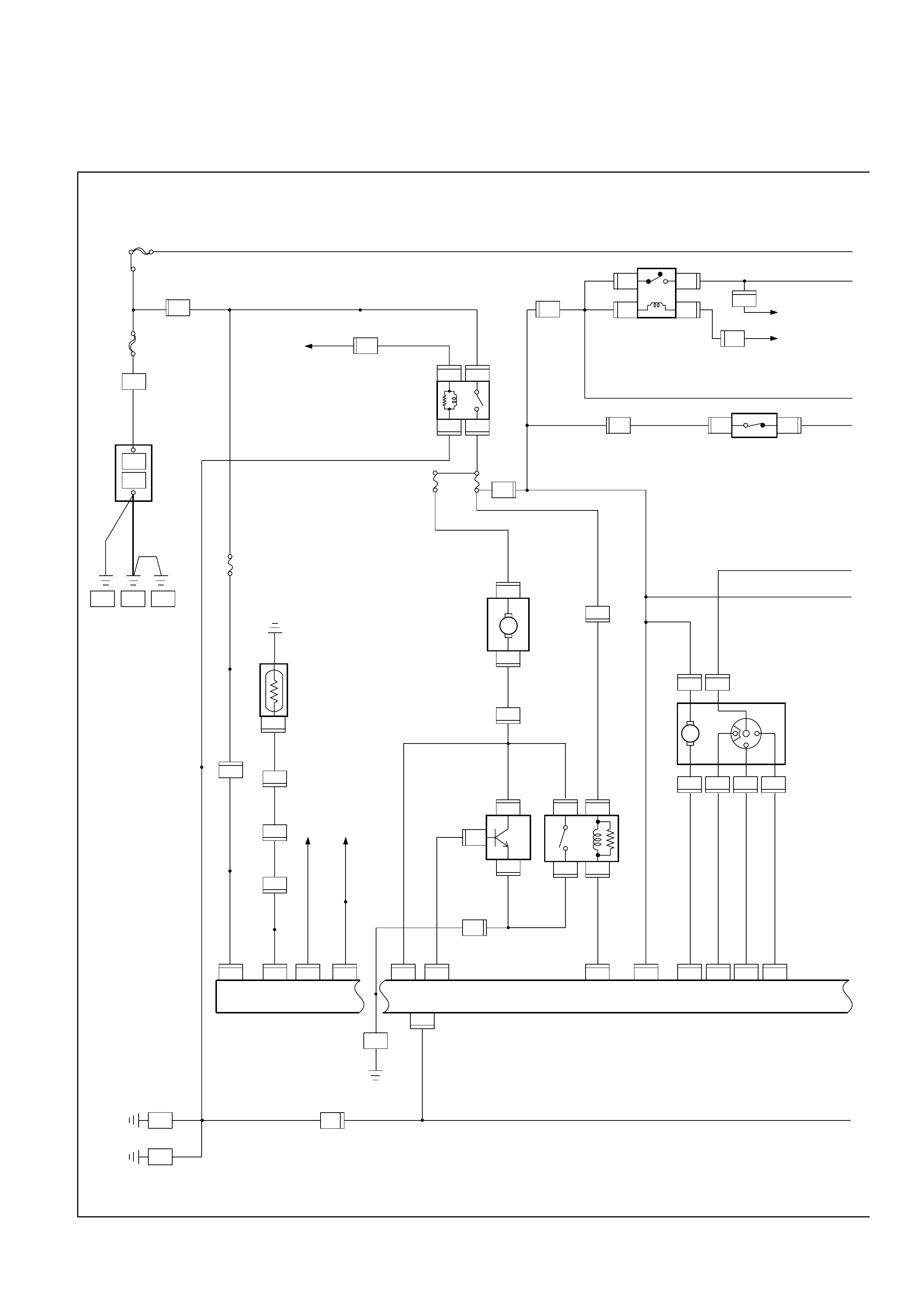
4JX1
X-21
2 4
13
X-21
X-21
THERMO SW RELAY
0.5BR
0.5BR
0.5G/Y
QWS THERMO SW
0.5G/B
X-21
B-19
B-18
BODY-RH
BODY-RH
I-32 I-33 I-32 I-32 I-33 I-33
84
I-32
9
I-32
10 7111213
1 2
B-36 B-36
B-36 B-36
34
9
H-26
5W 3W
5W
3L/R
C-16
CLOCK, ROOM
BODY ENG. FRAME
10A
0.5Y/B 0.5Y/B 0.5Y/B
0.5R/G
0.5G/R 0.5G/R
ILLUMINATION
CONTROLLER
TAIL RELAY (4)
0.5R/W0.3R/W 0.5R/W0.5R/W
0.5BR 0.5BR
0.5BR
HEATER
& A/C RELAY
CHARGE
RELAY(1)
P-1
P-5
P-2
P-7P-10P-6
5B
30B
8B
8B/R
FL-1
80A MAIN
+
AUTO A/C CONTROL UNIT
I-32
H-27 1.25B
0.5B
20
1.25B
I-33
14
I-49
4612
M
I-49 I-49 I-49
I-49
35
I-49
16
0.5L/O
0.5L/W
0.3L/R
0.3L/Y
0.3B/L
1.25B 0.3B
0.5BR
C-25 C-25 21
H-26
16
0.5G/W
0.5LG
PRESSURE SW
INTAKE
ACTUATOR
H-14
1
H-13
10 0.85W/G0.85W/G
5W
0.5B
0.5BR
H-16
7
3
H-4
0.5Y/B 0.5Y/B
12
H-17
1
H-24
0.5BR
3W/L
FL-3
40A C/HEAT
2
H-41 0.5G/Y ECM(J1-23)
H-2413
5
H-41
E-23
THERMO UNIT
12
I-32
3L
2L/B2L/B
C-19 25A
BLOWER
BLOWER
MOTOR
C-20 10A
A/C
I-50
2
2B
2B
0.3GR/W
0.5L/B
0.3BR0.3BR
2L/B2B
19
I-33 33 22 34 19 18 1712
0.3GR/L
MAX HI RELAY
POWER
TRANSISTOR
I-513
H-26
10
I-51
4
I-50
3
I-51
2
I-50
1
I-51
1
B-5
2
B-5
1
H-20
2
17
I-33
143536721
29
H-20 1
M
B-1
D08RY00114
AUTO A/C CONTROL UNIT
0.3B/L
0.3G/W 0.3G/W
I-34
2
10 9 8 11 23 24 16 6 25 26 1 2 3 4 32 31 20 13
3
I-34
M
I-34
14
I-34
2
1
C-86
H-24
0.3LG/B
1
2
C-86
9
H-24
I-33
1
I-35
3
I-33
0.3BR/B
0.5B
0.3LG/B
8
I-352
0.3LG/W
0.3B/L
0.3B/L
20
0.3LG/W
I-33
0.3B/L
M
6
6
I-32
I-45
H-674
I-45
3
H-67
8
2
15
I-33
H-676
8
5
I-32
H-675
7
5
I-33
H-677
I-45 I-45 I-45
0.3V/W
0.3V/R
0.3V/G
0.3V
0.3V/W
0.3V/R
0.3V/G
0.3V
M
1
4
B-69
H-25
11
9
45
3
H-25
12
3
10
H-26
18
0.3Y/BR
0.3Y/G
0.3GR
I-32 I-32 I-33
0.3Y/BR
0.3Y/G
0.3GR
B-69 B-69 B-69
B-69
VENT FOOT DEFB/L D/F
4
H-26
11 18
I-33I-33
1
X-12
2 4
13
X-12
X-12
X-5
2 4
1 3
X-5
X-5 X-5
0.5BR
11
H-41 0.5G/W
0.5G/O
0.5P/G
27
H-6H-41
4
H-17 E-27
0.5G/O
0.5G/O
A/C THERMO
RELAY
0.5G/O
ECM(J1-31)
INCAR SENSOR
AMBIENT SENSOR
SUN SENSOR
DUCT SENSOR
MIX
ACTUATOR
MODE
ACTUATOR
I-33
8
B-69
27 6
B-69 B-69 B-69
14
I-32
MAGNETIC
CLUTCH
I-40
1
I-40
9
H-26
19
0.3GR/R
I-33
0.3GR/R
8
H-255
0.3GR/G
I-33
0.3GR/G
7
H-261
0.3GR/L
I-33
0.3GR/L
0.3GR/R
0.3B/L0.3B/L
0.3B/L
0.3G/B
0.3GR/G
0.5P/G
0.5P/G 16
H-16
CERAMIC
HEATER RELAY
CERAMIC
HEATER
DIODE
13
I-32
B-1
3W/L
0.5G/B 1B-44 2
B-44
0.5Y/G 0.5Y/G
11
H-15 0.3G/W
1
B-48
2
B-48
3W/G 15
H-13 3W/G 2B
BODY-LH
X-12
26
H-16
H-16
17
H-25
4
D08RY00115

FUNCTIONS AND FEATURES
• Automatic interior temperature control
This function enables to maintain the interior temperature at the level specified from the temperature
control switch despite of changes in factors such as vehicle speeds, outside air temperature and number
of passengers.
• Maximum cooling and heating function
You can select FC (Full cool, namely maximum cooling temperature) or FH (Full heat, maximum heating
temperature) from the temperature control lever.
• Automatic air flow control
Air flow is automatically and consecutively fine tuned according to the specified interior temperature and
changes in aperture of the heater unit mix door.
• Mode (blow port) control
This function automatically selects either one of the VENT, BI-LEVEL, FOOT or DEP mode for the blow
port according to changes of temperature on the blow port. Using the mode switch allows you to select a
desired blow port manually.
• Intake (switching between the fresh air intake and circulation of interior air) control
The intake (switching between fresh air intake and circulation of interior air) mode automatically selects
either FRESH (fresh air intake), MIX or RECIRC (interior air circulation) according to changes of the blow
port temperature. Using the intake switch allows you to select a desired intake port manually (in the
manual operation, FRESH and RECIRC modes alone are available). Pressing the DEF (defrost) mode
switch selects the FRESH (fresh air intake).
• Cooler start-up timing control
This function is used for maintaining the air flow at "LOW" level until the evaporator is sufficiently cooled
down. It is intended to prevent a large volume of hot air being blowing into inside of a vehicle when the
cooler is turned on in hot summer season.
• Heater start-up timing control
This function is used for maintained the air flow at "LOW" level and also for maintaining the defrost
mode until temperature of coolant in the heater core is sufficiently heated. It is intended to prevent a
large volume of cool air being blown into inside of a vehicle when the heater is turned on in cold winter
season.
• Solar radiation quantity offset control
The photodiode on the solar radiation sensor determines solar radiation quantity accurately to offset
interior temperature quickly.
• Switch position storing function
This function is used for storing switch positions being selected in the immediately preceding operation,
namely the last time the ignition has been turned off. It simplifies the setup procedures when restarting
the system.
• Self-diagnosis function
The self-diagnosis function turned on from the panel switch makes your troubleshooting easier (for detail
of this function, refer to the section titled "Self-Diagnosis").

FULL AUTO display
INTAKE indication
(LED)
(switching between
fresh and interior air)
MODE indication
(LED) (Blow port)
AC display (LED)
FAN indication (LED)
FAN KNOB
AUTO SET
REC FRESH SWITCH
TEMP LEVER
(temperature control)
MODE SWITCH
(blow port selection)
AC SWITCH
IN CAR SENSOR
AMBIENT SENSOR
SUN SENSOR
DUCT SENSOR
MIX ACTUATOR
POTENTIOMETER
MODE ACTUATOR
POTENTIOMETER
AIR MIX DOOR
MODE DOOR
INTAKE ACTUATOR
REC INTAKE DOOR
FAN MOTOR
POWER
TRANSISTOR
AUTOMATIC HEATER/AIR CONDITIONER CONTROL UNIT (with the built-in micro-computer)
MAX HI RELAY
PRESSURE
SWITCH AIR CONDITIONER
THERMO RELAY
COMPRESSOR
SWITCH
MAGNET
CLUTCH
PCM
PRESSURE
SWITCH AIR CONDITIONER
THERMO RELAY MAGNET
CLUTCH
(4JX1engine)
MIX FRESH
FULL AUTOMATIC AIR CONDITIONER BLOCK DIAGRAM
F01RY00009
10
7
1
1
5
6
12 13
11
2
3
4
8
9
852RY00001
Legend
(1) Liquid Line (High Pressure Pipe)
(2) Pressure Switch
(3) Ambient Sensor
(4) Receiver Drier
(5) Discharge Line (High Pressure Hose)
(6) Suction Line (Low Pressure Hose)
(7) Compressor
(8) Condenser Assembly
(9) Drive Belt
(10) Compressor Bracket
(11) Drain Hose
(12) Evaporator Assembly
(13) O-ring
AIR CONDITIONING PARTS
6VE1
10
7
13
6
5
12
14
11
15
2
1
3
9
8
4
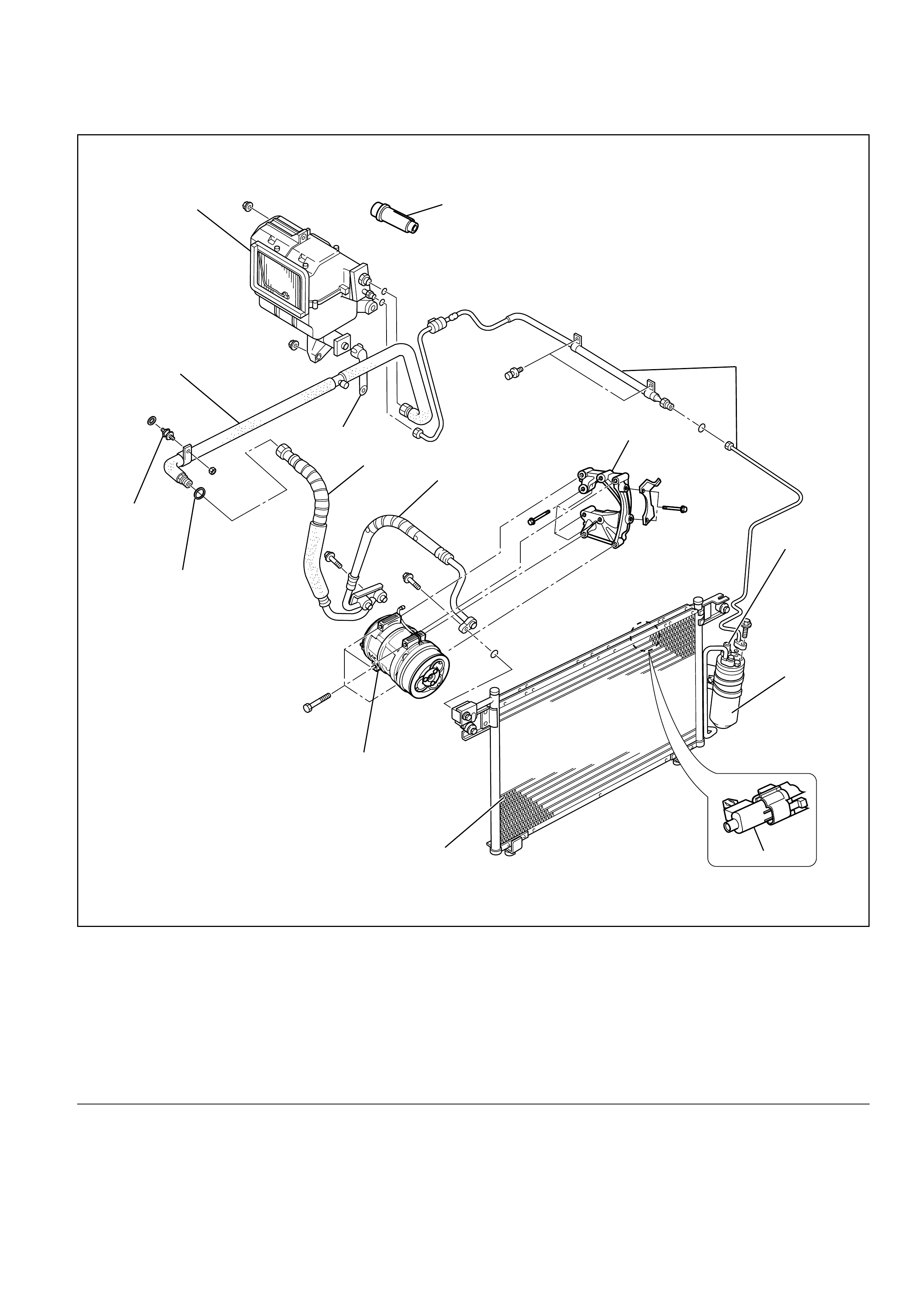
852RY00003
Legend
(1) Liquid Line (High-Pressure Pipe)
(2) Pressure Switch
(3) Receiver Drier
(4) Ambient Sensor
(5) Compressor Bracket
(6) Discharge Line (High-Pressure Hose)
(7) Suction Line (Low-Pressure Hose)
(8) Compressor
(9) Condenser Assembly
(10) O-ring
(11) Insulator Pipe
(12) Suction Line (Low-Pressure Pipe)
(13) Drain Hose
(14) Evaporator Assembly
(15) A/C Switch
4JX1
865RY00026
12
678
345
MAX MAX
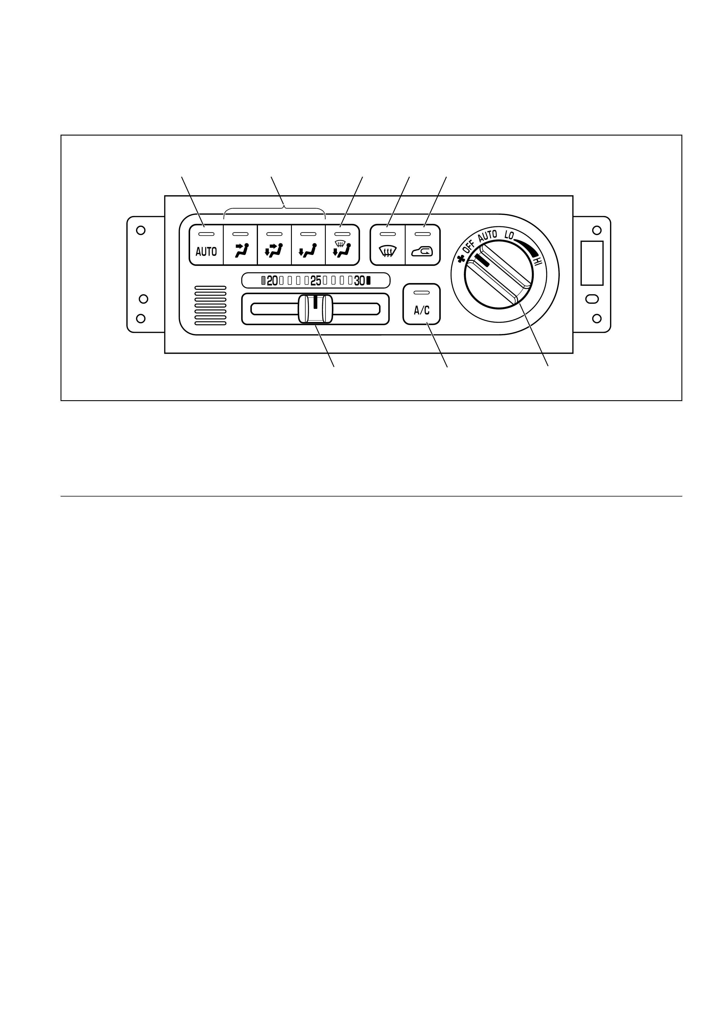
Legend
(1) Auto Switch
(2) Mode Switch
(3) DEF/FOOT Switch
(4) DEF Switch
(5) Intake Switch
(6) Fan Switch
(7) Air Conditioning Switch
(8) Temperature Control Knob
Control Panel Layout
C01RY00001
2
1
12
34
10 9
6
5
8
7
11
13
BB
A
C
B
C
A
A
B
B
A
A
B
A
A
B
B
A
C
A
A
C
CC
B
A B
A A B B
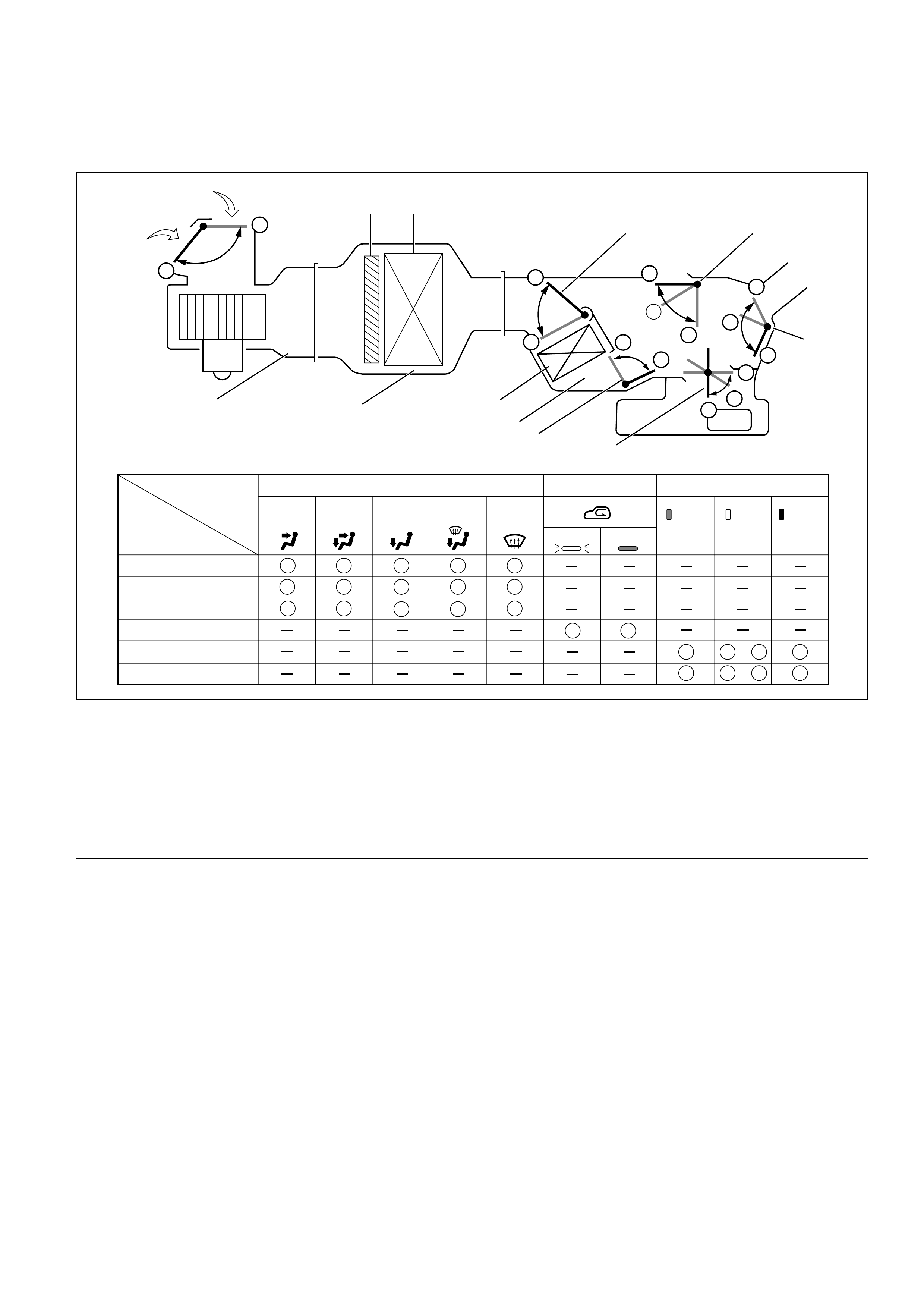
Vent Door
Mode Position Display of Intake Status Set Temperature
ON FULL
COLD FULL
HOT
20~30
B B A A
Blue
VENT BI-LEVEL FOOT DEF Red
OFF
Foot Door
DEF Door
Intake Door
Air Mix Door
Sub Air Mix Door
White
C
C
B
DEF/FOOT
C
A
Legend
(1) Interior Air Intake
(2) Fresh Air Intake
(3) Pollen Filter
(4) Evaporator Core
(5) Air Mix Door
(6) DEF Door
(7) Vent Door
(8) Foot Door
(9) Sub Air Mix Door
(10) Heater Unit
(11) Heater Core
(12) Evaporator Unit
(13) Blower Unit
Air Control Functions
OPERATION AND FUNCTIONS OF CONTROL PANEL SWITCHES
1. Auto Switch
(1) Pressing this switch turns on the automatic control mode. It resets all manual switches except that
for the fan control. However, when the Manual REC is selected for the intake or the Manual Open is
selected for the C/V, these modes are maintained.
(2) It causes the A/C (air conditioner) to the ON mode (this function, however, available only when the
fan is turned on and also the compressor is turned on because of the given outside air temperature
level).
<Indication>
• The AUTO LED comes on.
• Currently selected mode for the Mode and Intake are respectively indicated.
2. Mode Switch
<Indication>
(1) Pressing the VENT, B/L or FOOT switch selects the corresponding mode.
(2) When the Auto is selected for the Mode and Intake, pressing the mode switch fixes the Intake to the
immediately preceding status.
<Indication>
• Turns off the Auto LED.
• Currently selected blow port is indicated.
3. DEF Switch
Press this switch to select the DEF mode.
<Indication>
*1: When the manual REC is selected for the Intake, the manual REC is maintained.
*2: The ON mode is enabled only when the fun is turned on, and also the compressor is turned on
because of the given outside air temperature level.
<Indication>
• The Auto LED is turned off.
• DEF is indicated for the blow port, A/C LED comes on (only when the fan is turned on), and status
display is provided for the Intake.
Example 1:
4. Intake Switch
Pressing this switch sequentially selects a different intake port in the following order.
Example 1:
Example 2:
PUSH
Auto REC FRESH REC
PUSH PUSH
PUSH PUSH PUSH
Auto REC
MIX REC FRESH
DEF SW:ON
(Selects the DEF
mode)
A/C OFF
mode A/C ON
mode A/C ON mode is
maintained.
Mode switches for other than
the DEF mode: ON
(Resets the DEF mode)
Blow port Intake port A/C MIX
DEF Auto FRESH *1 ON mode *2 Auto
<Indication>
• The Auto LED maintains unaffected.
• Currently selected intake port is
indicated.
5. Fan Switch
(1) Sets the fan to the specified mode.
(2) Even when the fan switch is turned off, status display for the Model and Intake is maintained.
6. Temperature Control Knob
(1) This knob is operable only when the fan is turned on. It may be used for the MAX control of each
block except the fan.
(2) When the manual mode is selected for the fan control, this manual mode is maintained.
<MAX Control>
*1: In the A/C: OFF mode, FRESH shall be selected.
*2: The ON mode is available only when ON is selected for the fan as well as for the cold outside air
ON/OFF selection.
*3: When the MAX control is selected from the DEF mode, this DEF mode shall be maintained.
Example 1:
Example 2:
<Indication>
• As long as the MAX control is selected, the immediately preceding indication shall be maintained for
the AUTO.
• Status display is provided for others.
7. Air Conditioning Switch
Pressing this switch turns on or off the A/C (air conditioning) control. (The compressor remains turned
off if the fan is turned off and also the compressor has been turned off because of the given outside air
temperature level.)
<Indication>
(1) The A/C LED remains turned on even if the compressor has been turned off because of the given
outside air temperature level. In this case, however, the AUTO or DEF switch must be turned on and
the A/C ON mode must also be turned on (by the MAX/C mode).
(2) Pressing the A/C switch from the above state (1) turns off the A/C LED.
<Intake port>
REC
MIX
FRE
<Display>
On
Off
Selects MAX/COOL
(1): Mode
Manual B/L VENT Resets MAX/COOL Returns to (1) status.
Mode: Manual B/L
Selects MAX/COOL
(1): Mode
Manual B/L VENT Resets MAX/COOL Returns to (1) status.
Mode: Manual B/L
Mix Fan Mode Intake A/C
MAX/COOL Full cool MAX/HI VENT REC*1 ON mode*2
MAX/HEAT Full hot AUTO/HI FOOT*3 FRESH Current status
is maintained
OVERVIEW OF CONSTRUCTION,
MOVEMENT AND CONTROL OF MAJOR
PARTS OF FULL AUTOMATIC AIR
CONDITIONER SYSTEM
Automatic Heater/Air Conditioner Control Unit
Equipped with the built-in micro-computer, this
control unit operates on signals from sensors and
input signals from switches to offer total control of
the blower fan, and actuators used for the mode
door, intake door and air mix door.
Its self-diagnosis function enables quicker access to
a failed part and its more accurate troubleshooting.
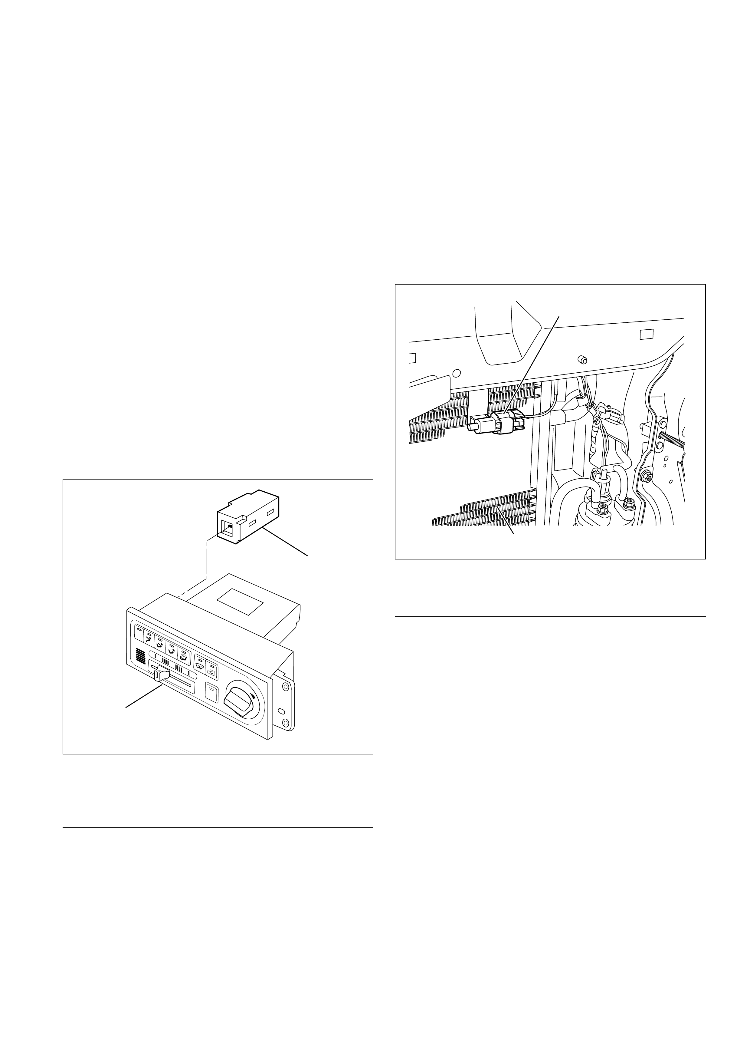
In Car Sensor
It is a sensor used for detecting room temperature
of a vehicle. This sensor converts a given room
temperature into a resistance value before entering
the data to the automatic heater/air conditioner
control unit.
This in car sensor unites the power driven aspirator
and the motor fan so that a small amount of room
air may be constantly fed to the sensor.
This sensor is provided on the control panel.
Legend
(1) In Car Sensor
(2) Full Automatic Air Conditioner Control Unit
Ambient Sensor
This sensor is used for detecting temperature
outside the vehicle. It converts a given outside air
temperature into a resistance value before entering
the data to the automatic heater/air conditioner
control unit.
Thermal effects from the condenser and radiator
during idling after a run can be measured and offset
the automatic amplifier.
This sensor is provided on the side plate situated at
upper right side of the condenser.
Legend
(1) Ambient Sensor
(2) Condenser Assembly
•Duct Sensor
The sensor is the sensor to detect temperature
change of the side of evaporator blower coming
by fresh recirculation of intake door or "on" "off"
of compressor.
The temperature is converted to resistant rate.
And it works as thermostat to control to prevent
freezing of evaporator.
This sensor is installed in the upper case of
evaporator.
2
1
865RY00006
2
1
845RY00001
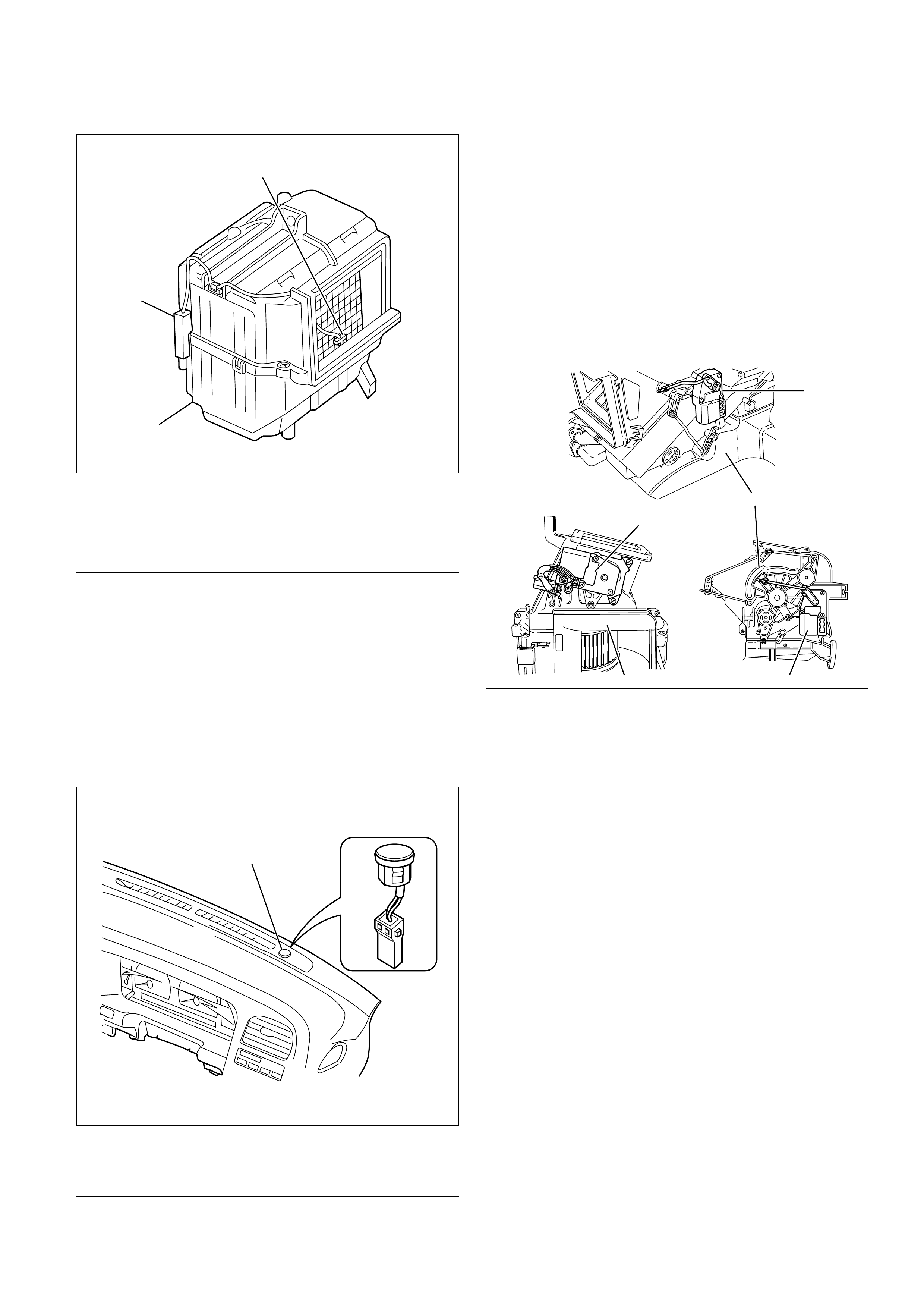
Legend
(1) Duct Sensor
(2) Evaporator Assembly
(3) Amplifierblock
In Car Sensor
It is a photodiode used for detecting quantity of
solar radiation. This sensor converts the offset
signal generated by changes in the interior
temperature (which results from fluctuations in
solar radiation) into photoelectric current to enter
into the automatic heater/air conditioner control
unit.
This sensor is provided at top of the defroster grill.
Legend
(1) Sun Sensor
Actuator
The actuators are power driven type containing a
small motor. Receiving output current from the
automatic heater/air conditioner control unit,
actuators drive the heater and blower unit mode
doors.
Actuators consist of the mode actuator used for
switching the mode (blow port selection), the mix
actuator used for changing aperture of the air mix
door, the intake actuator used for switching the
intake mode(fresh air/interior air).
Legend
(1) Mix Actuator
(2) Heater Unit
(3) Mode Actuator
(4) Blower Unit
(5) Intake Actuator
The actuator changes the motor speed using the
gear and drives each door rotating the output axis
united with the sliding contact.
2
3
1
860RX013
1
826RY00001
This illustration is based on RHD
2
5
43
1
860RX012
This illustration is based on RHD
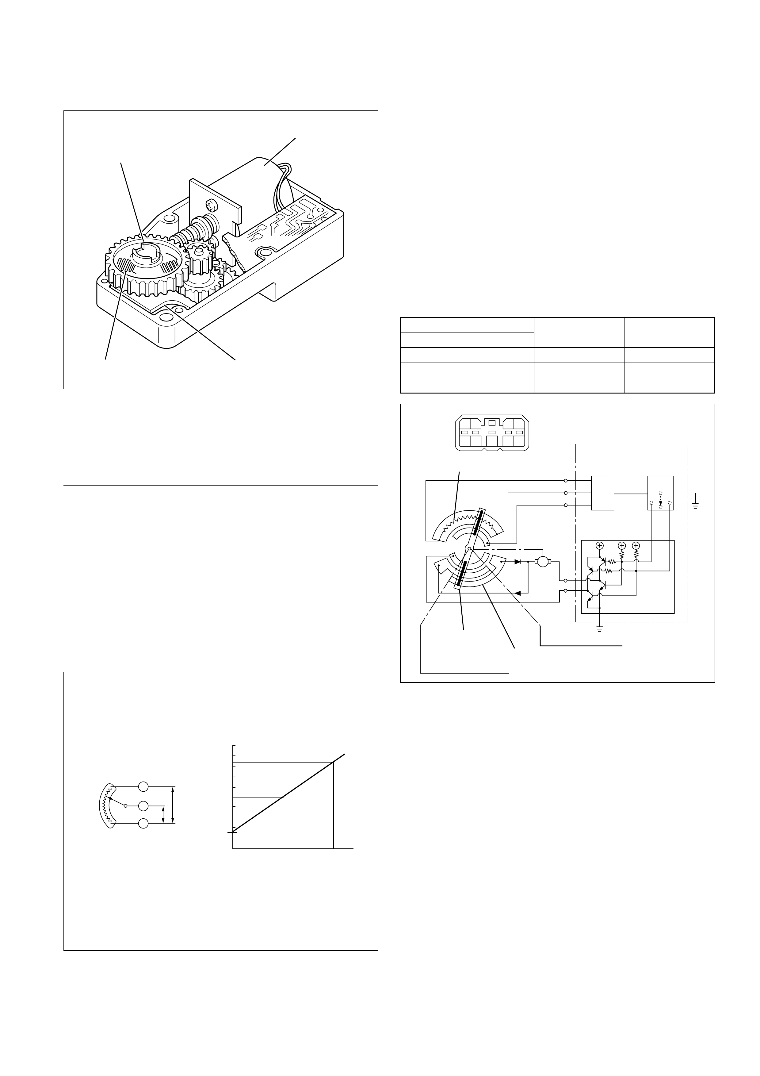
Legend
(1) Out put Axis
(2) Motor
(3) Printed Circuit Board
(4) Sliding Contact
The mode and mix actuators are common actuators
with the built-in potentiometer. For the intake
actuator, the contact switch type is selected.
The potentiometer is a register assembled to the
printed circuit board of the mix and mode
actuators. It detects the air mix door position
specified by rotation of the output axis as a ratio of
the variable terminal (VM) voltage against the
reference voltage (VDD: 5V), then signals the value
to the automatic heater/air conditioner control unit.
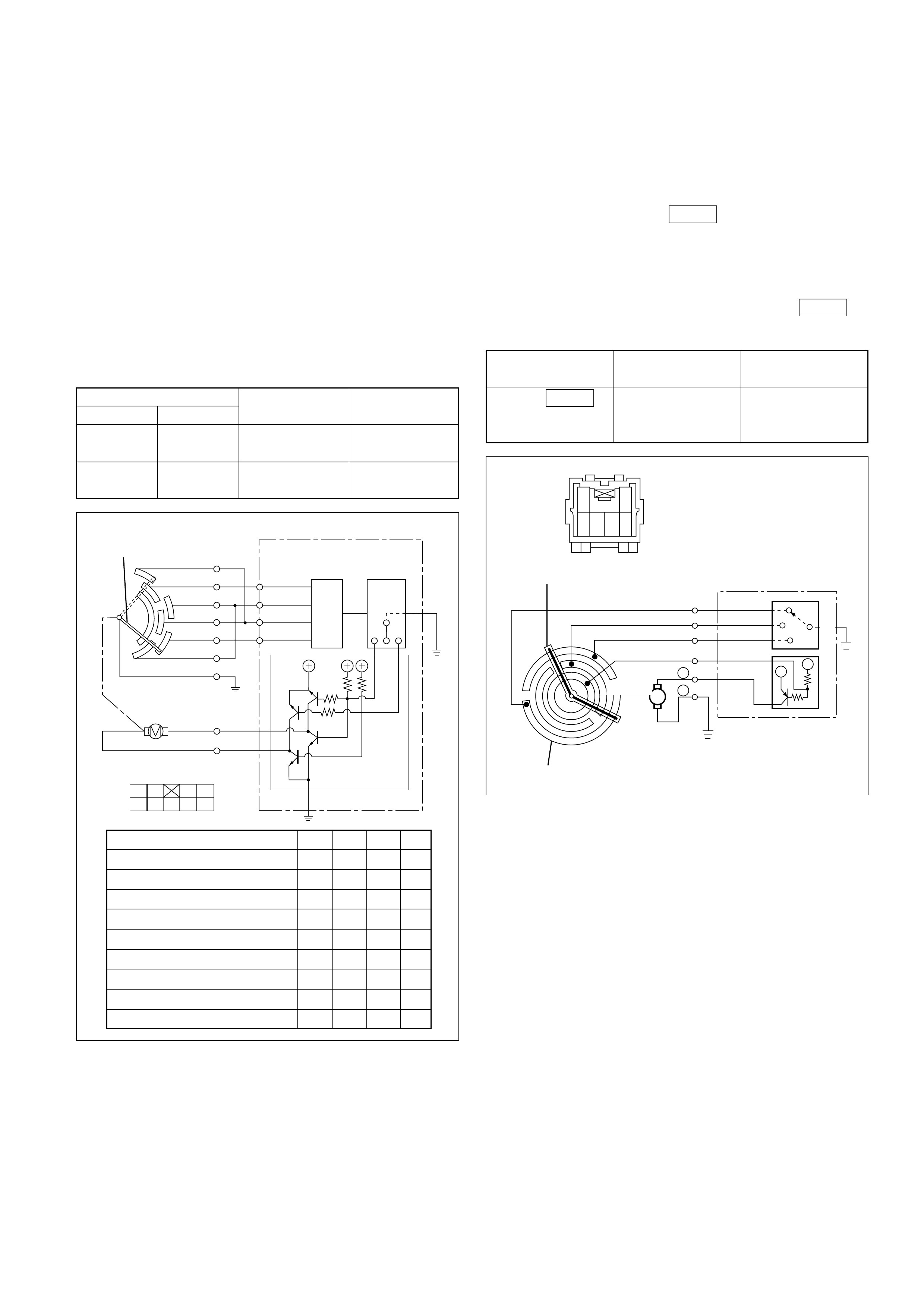
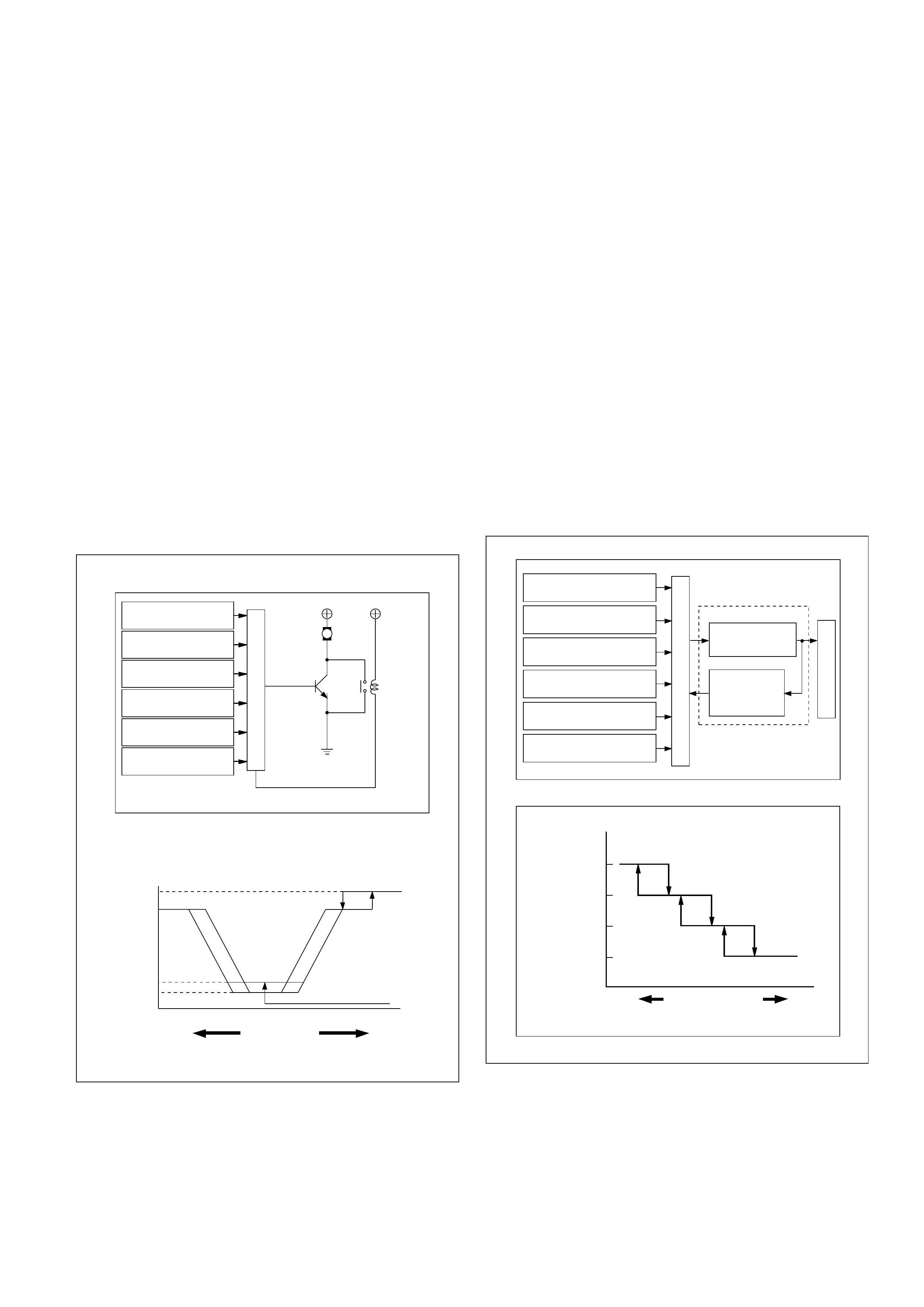
•Movement of Mix Actuator
Position of the air mix door is determined by the
controller on the automatic heater/air conditioner
control unit.
As the heat or cool side of the controller is
grounded, the transistor on the driver is activated
and, thus, the motor rotation is turned on. The
sliding contact connected to the motor sends the
position detection signal from the potentiometer
to the automatic heater/air conditioner control
unit. As the set temperature and interior
temperature are balanced, the controller returns
to the neutral and the motor rotation is stopped.
1
2
43
860RW026
C01RX016
M
N
3
2
7
6
8
98
43
65
21
7
Potentiometer
Connection
Position
Detection
Block
Automatic Heater / Air
Conditioner Control Unit
Controller
Sliding Contact
Full Heat PositionTerminal Plate
Full Cool Position
Driver
Cool Side
Heat Side
C01RY00016
Full cool
Full cool
0
0
0.5
1.0
50 100%
Aperture of air mix door
Voltage ratio VM/VDD
Full heat
Full heat VDD
VM
+
–
I-45 Rotation
(+) side (–) side direction Remarks
8 6 Clockwise Full heat side
6 8 Counter Full cool side
clockwise
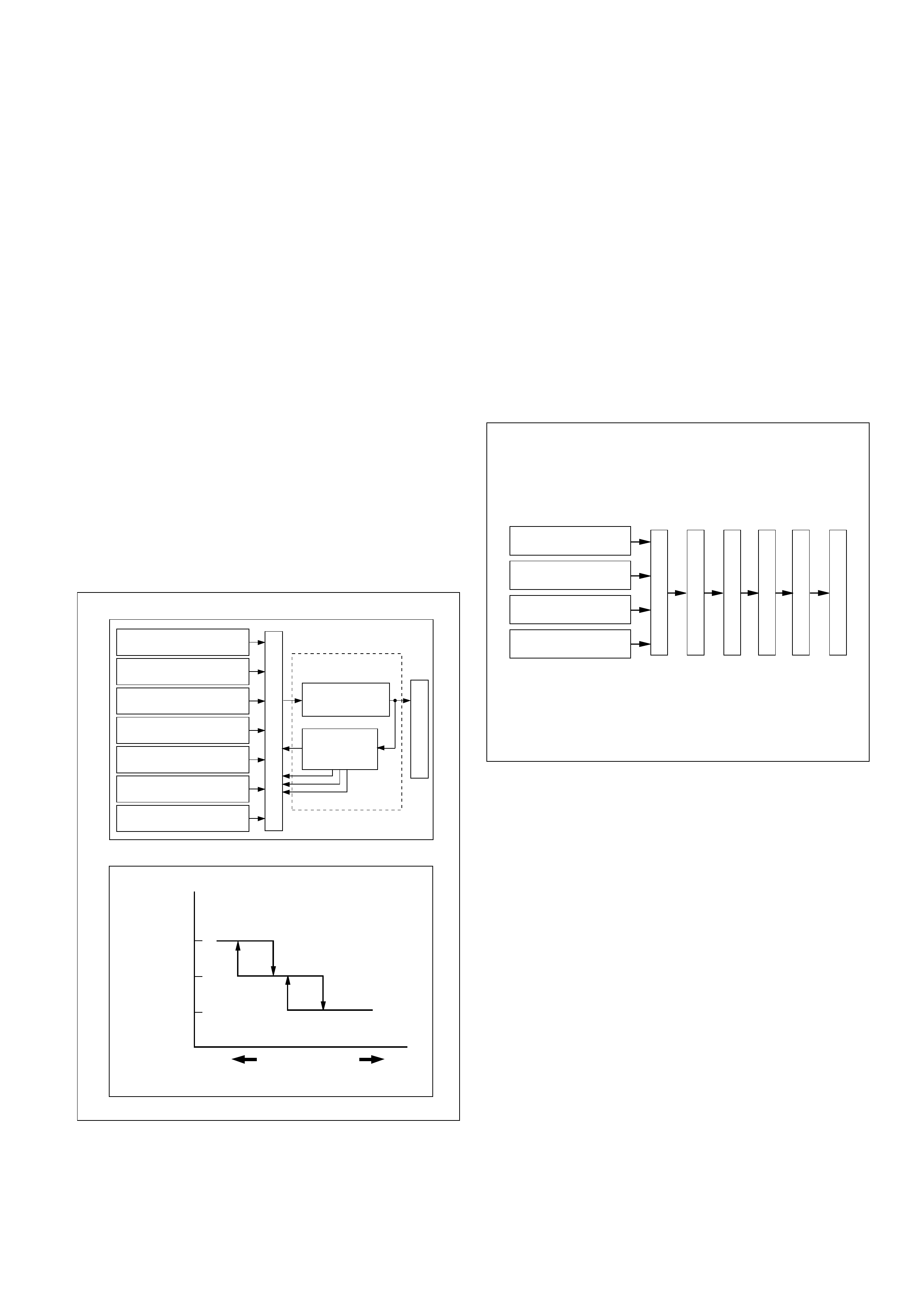
•Movement of Mode Actuator
As target position of the mode door is decided on
the controller of the control unit, the control unit
reads the position detection signal from the
actuator to select the clockwise or counter
clockwise motor rotation direction.
Grounding the controller VENT or DEF side after
the direction selection activates the transistor on
the driver, thus turning on the motor rotation.
Accompanying the motor rotation, the sliding
contact rotates, too. When the target position is
reached, the controller on the control unit returns
to the neutral and the motor stops.
•Movement of Intake Actuator
The controller on the automatic heater/air
conditioner control unit selects an intake mode to
be used.
As the Terminal No.5 is grounded via the
sliding contact on the terminal plate, the
transistor on the driver is activated, thus turning
on the motor rotation. Then, accompanying
move of the motor, the sliding contact rotates
until grounding of the Terminal No.5 is
removed, thus stopping the motor. I-49
I-49
Driver
Controller
DEF side
VENT
side
Position
detection
block
Control unit
Sliding
contact
Actuator side
42
98
37
78910
HLHL
HHHL
HHLL
HHLH
HLLH
HLHH
LLHH
LHHH
LHLH
61
5
Interconnected
motor
VENT
VENT
Mid point between VENT - B/L
B/L
Mid point between B/L - FOOT
FOOT
Mid point between FOOT - D/F
D/F
Mid point between D/F - DEF
DEF
DEF 7
8
9
10
2
6
7
8
3
4
9
5
1
C01RX017
M
+
6
12
6543
REC
MIX
FRESH
Com
1
2
5
3
4++
—
Terminal Plate
Auto A/C
Control Unit
(Actuator Side)
Driver Controller
Sliding Contact
Connected
C01RX006
Conducting pin Rotation
(+) side (–) side direction Remarks
5 1 Clockwise VENT to
DEF direction
1 5 Counter DEF to
clockwise VENT diction
Grounding Rotation
terminal direction Remarks
No.5 Clockwise RE-CIRCULA
TION→MIX
→FRESH
I-49
OVERVIEW OF AUTOMATIC CONTROL OF
FULL AUTOMATIC AIR CONDITIONER
The full automatic heater and air conditioner on this
vehicle has the following features:
•Interior temperature control.
•Air flow control.
•Mode (blow port) control.
•Intake (switching between fresh air and interior
air) control.
•Heater start timing control.
•Cooler start timing control.
•Evaporator anti-freeze control.
1. Interior Temperature Control
The automatic heater/air conditioner control unit
operates on the setup temperature signal from
the temperature control switch and other sensor
signals to derive the total signal. Then, the
control unit compares this signal against the
signal from the potentiometer to determine
rotation direction of the mix actuator. The mix
actuator moves the air mix door to the aperture
specified by the total signal so that the specified
interior temperature is achieved.
If the compressor is turned off in the A/C (air
conditioning) mode, aperture of the air mix door
is offset according to the outside air temperature
or the specified interior temperature. This
function removes the difference in the blowing
temperature in this state and that of when the
compressor is turned on.
When FH or FC is selected for the setup
temperature, the air mix door is accordingly
fixed to the Full Heat or Full Cool mode.
When the VENT mode is selected, aperture of
the air mix door is controlled so that excessively
heated air may not be blown from the VENT
blow port.
0
50
140 104 68 32
Air mix door aperture
Full cool
Heater
side
Restriction on the
aperture enabied
in the VENT mode
Air conditioning
ON mode
Full heat
Set temperature
signal
Mix
actuator
Potentio
meter
Air mix door
In car sensor
Ambient sensor
Sun sensor
Control unit
Air conditioning
switch
Set up temperature
signal
Air conditioning
OFF mode
Total signal Cooler
side
C01RY00011
2. Air Flow Control
•In the Auto Mode
The automatic heater/air conditioner control unit
operates on the setup temperature signal and
other sensor signals to derive the total signal.
Then, the control unit adjusts base potential of
the power transistor to match it to the voltage
pattern of the target fan so that stage-less fan
speed control can be achieved.
When solar radiation quantity is detected in the
VENT or B/L mode, the control unit increases the
minimum fan voltage to offset.
When FH or FC is selected from the temperature
control switch, air flow is accordingly fixed to
MAX HI or AUTO HI.
•In the Manual Mode
Air flow specified from the fan switch is entered
to the automatic heater/air conditioner control
unit as the manual signal. The signal modifies
the air flow to the level specified from the fan
switch so that the required fan voltage is
attained.
3. Mode (Blow Port) Control
The automatic heater/air conditioner control unit
operates on the setup temperature from the
control switch, and temperature and solar
radiation quantify from the sensors to determine
the total mode control signal. According to the
pattern specified by this signal, the control unit
selects either one of the VENT, BI-LEVEL, FOOT
or DEF/FOOT mode.
The mode actuator determines the rotation
direction comparing the target position against
the current position being determined by the
position detection signal.
When FH or FC is selected for the temperature
from the temperature control switch, mode is
accordingly fixed to the VENT or FOOT.
•In the manual operation of the mode switch, you
can select a desired blow port mode pressing
the corresponding mode switch.
•Operating the DEF mode switch selects the DEF
for the blow port mode.
4.5
12
(V)
M
MAX
HI Relay
Power
transistor
4.8
10.5
MAX HI
Set up
temperature signal
Control unit
In car sensor
Ambient sensor
Sun sensor
Mode control
signal
Fan switch
AUTO HI
Heater
side Cooler
side
Total signal
VENT mode
Blower fan motor terminal voltage
C01RY00008
Mode control
DEF / FOOT
Set up temperature
signal
Mode actuator
Mode door
Position
detection
switch
Control unit
In car sensor
Sun sensor
Air conditioning
switch
Mode control
signal
Ambient sensor
FOOT
BI-LEVEL
VENT
Heater
side Cooler
side
Mode total signal
C01RY00009
4. Intake (Fresh air/interior air switching) Control
In the Full Auto mode, the automatic heater/air
conditioner control unit operates on the setup
temperature signal and other sensor input
signals to derive the total signal. According to
the pattern specified by this signal, the control
unit provides the intake control.
When the fan is turned off or the A/C (air
conditioning) is turned off, the intake is fixed to
the FRESH mode.
When FC or FH is selected from the control
switch, the intake mode is accordingly fixed to
the RECIRC or FRESH.
•In the Manual Operation
Pressing the FRESH (fresh air intake) or the
RECIRC (room air circulation) accordingly selects
the FRESH or RECIRC mode.
•When the DEF Mode Switch is depressed
The intake mode is fixed to the FRESH. When
the MANU REC is selected, however, the mode
is fixed the RECIRC.
•When the Mode Switch is depressed
If the automatic intake control is selected, the
intake is fixed to the currently selected mode.
5. Compressor Control
In the automatic control mode, the automatic
heater/air conditioner control unit turns on or off
the compressor with the evaporator anti-freeze
mechanism using the duct sensor. And, when
outside air is detected to be low through the
ambient sensor signal, the control unit turns off
the compressor using the compressor control
function.
•Manual Control
In the automatic control mode, pressing the A/C
(air conditioning) switch turns off the
compressor.
•Pressing the DEF mode switch automatically
turns on the compressor.
Intake door open / close
RECIRC
Setup temperature
signal
Intake
actuator
Position
detection
switch
In car sensor
Ambient sensor
Sun sensor
Compressor
ON / OFF
Fan ON / OFF
Intake switch
Control unit
Intake door
MIX
FRESH
Heater
side Cooler
side
Total mode signal
C01RY00012
Ambient sensor
Control unit
Pressure switch
Thermo switch relay
ECM
Compressor relay
Compressor
Electronic
thermostat
Air conditioning
switch
Set up temperature
signal
C01RY00010
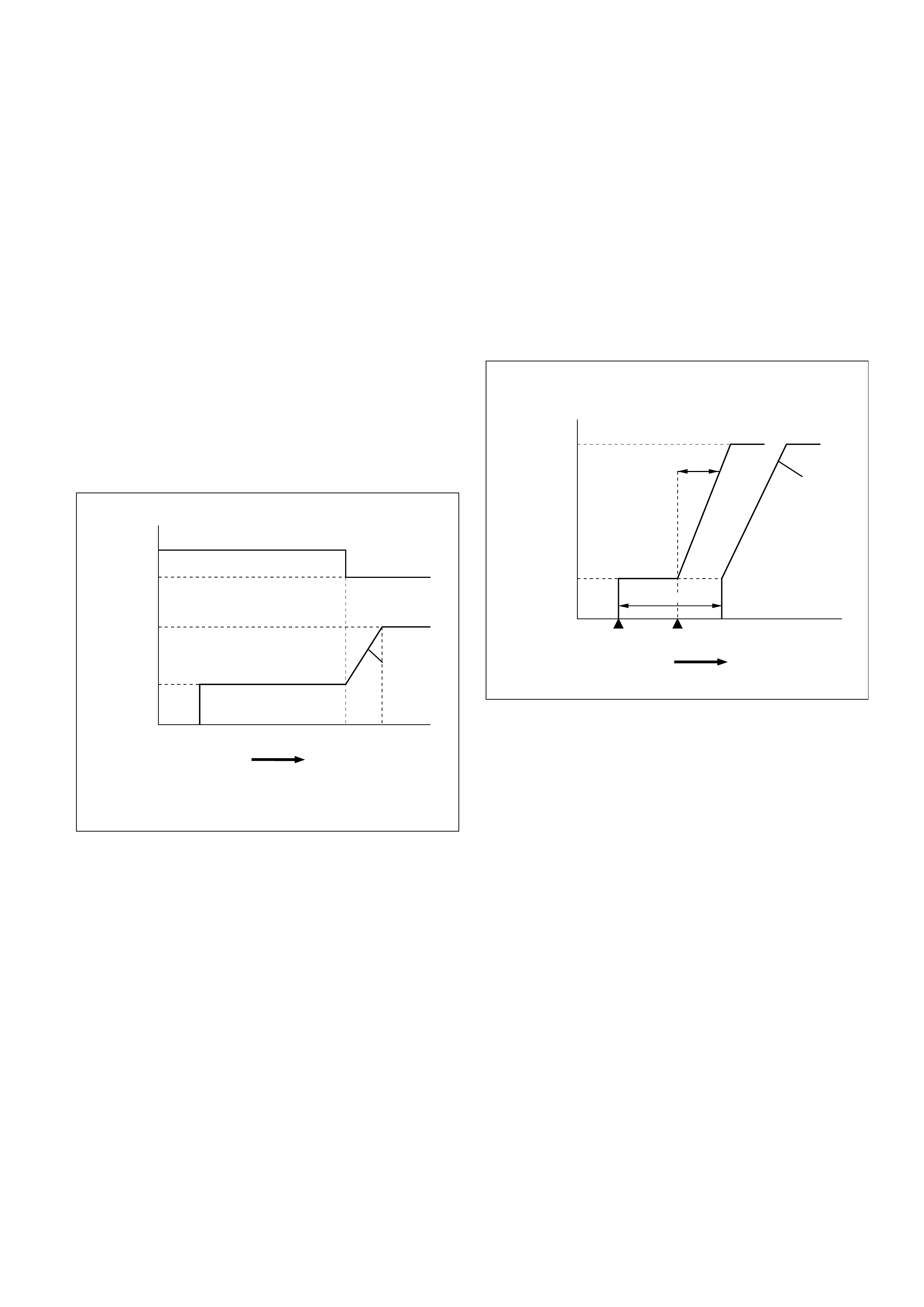
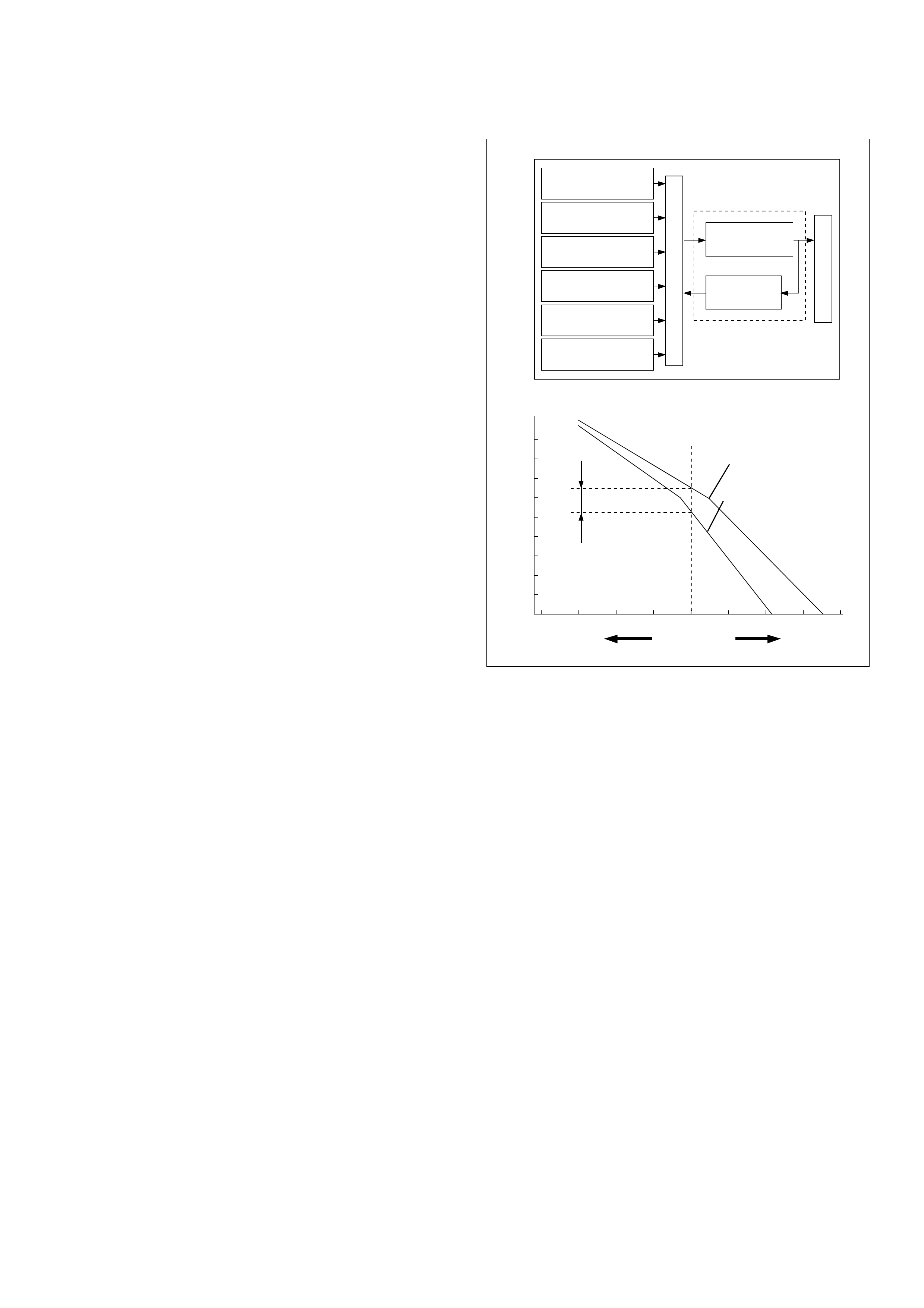
6. Heating Start Timing Control
When the automatic heater/air conditioner is
started, heating is turned on under following
conditions.
•The detected temperature of thermo unit is
136°F or less.
•The temperature setting signal and the total
signal by each sensor meet the condition of
heating.
When the detected temperature by the coolant
temperature sensor is 136°F or less the blower
fan motor is set to work at low speed and the
"DEF" mode is selected.
When the detected temperature by the coolant
temperature sensor is 77°F or more, the blow
mode changes automatic control. And the
blower fan speed is controlled to be lineally up
from "LO" to "MAX HI".
7. Cooling Start Timing Control
When the automatic heater/air conditioner is
started, cooling is turned on under following
conditions.
•The in car sensor is 86°F or more.
•The temperature setting signal and the signals
from each sensor meet the specified condition.
The blower fan speed is set to "LO" for
maximum 7 seconds when cooling start
conditions meet, and then, is controlled to be
lineally up to "MAX HI" by 5.32%/S.
Ignition swich
"ON" Time
Blower voltage to turn
on the cooling
7 SEC maximum
3 SEC
100%
(MAX HI)
33.5%
(LO)
5.32%/S
C06RY00001
33.5%
(LO)
2.63%/S
Mode
DEF
Auto
Mode
100%
(MAX HI)
Ignition
switch "ON"
Thermo Unit 58¡C(Gasoline)
52¡C(Diesel)
Time
840RY00009
TROUBLESHOOTING
Troubleshooting - It's Overview and Procedures
The full automatic heater and air conditioner equips with the "Self-Diagnosis Function" to check its major
components.
This function makes access to the sensors, actuators and blower fan motor system easier when checking
them up and, when a failed part is located, this function restores its original performance.
When implementing the troubleshooting, this self-diagnosis function narrows the range to be searched at
the first step, then check relevant parts one by one according to the "Checking Procedures by Failed
Location" As for a location this function is unappreciable, the system accurately determines characteristics
of a given trouble and checks relevant parts according to the "Checking Procedures by Failed Location".
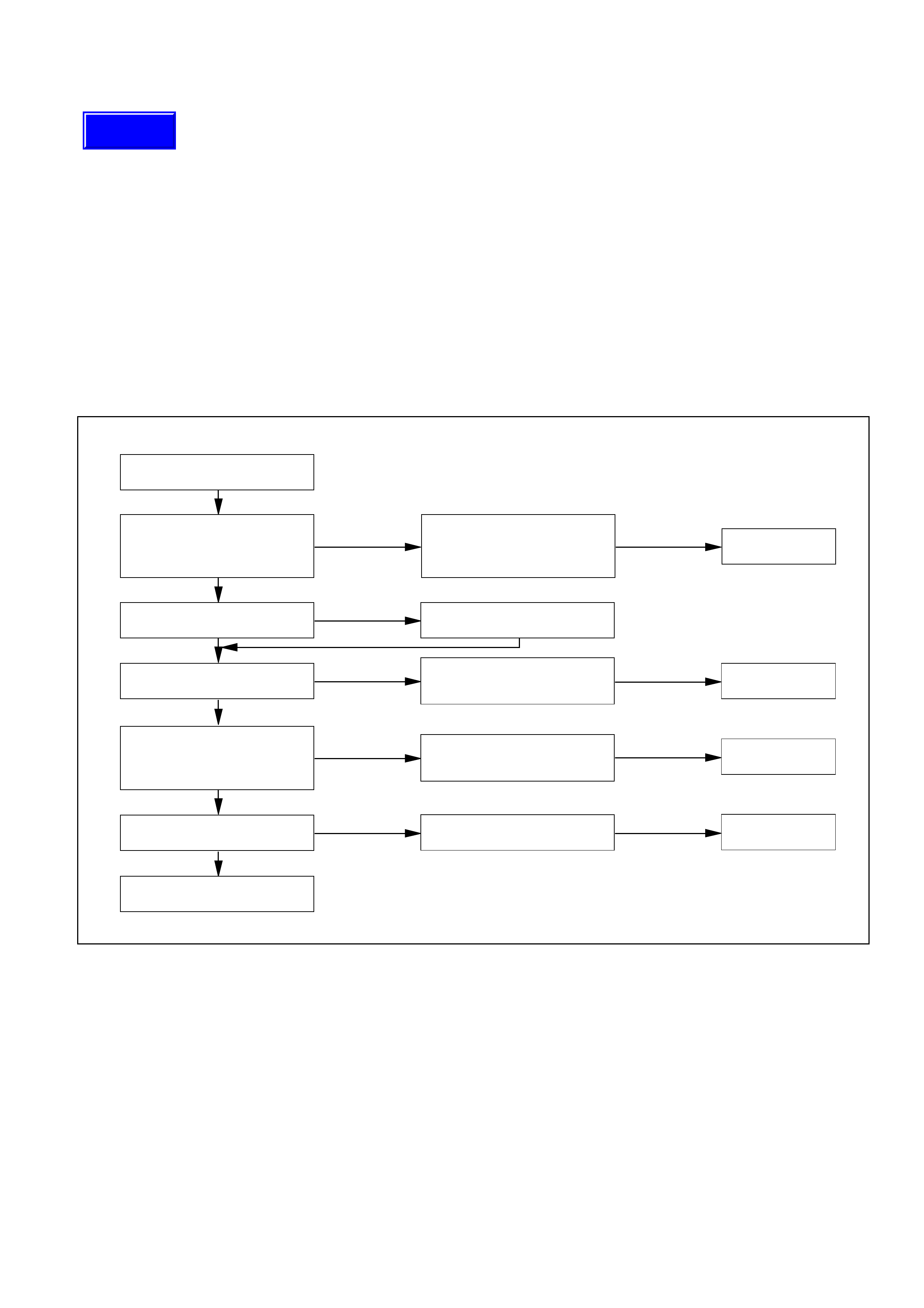
The following illustrates basic troubleshooting flow.
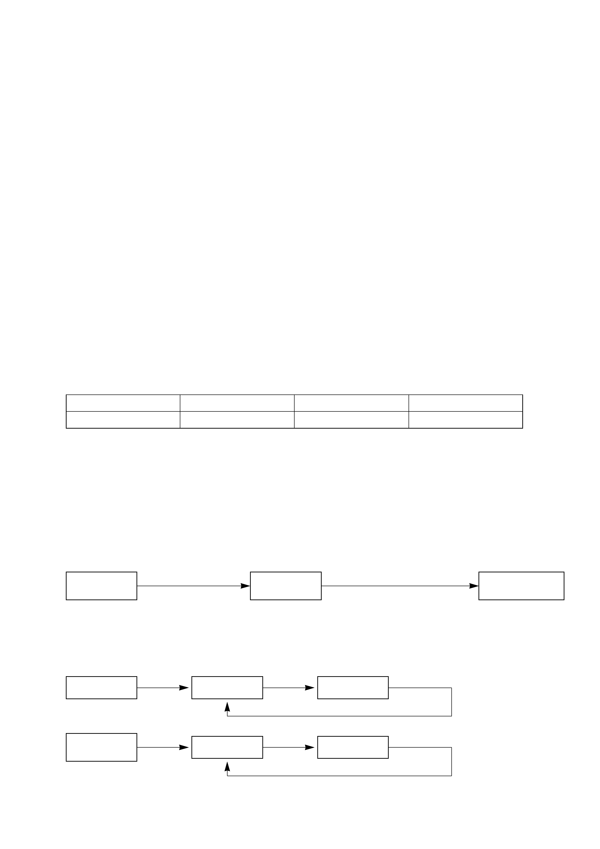
1. Basic Troubleshooting Flow
Occurrence of a trouble
Refer to the check list for
the inspection. Locate the failed location.
Check the failed part.
Correction
Correction
Correction
Troubleshooting by the
self-diagnosis function.
Reference the "Check
Procedure by Failed
Location" for the inspection.
Reference the "Check
Procedure by Failed
Location" for the inspection. Correction
Check the cooling / heating
cycles.
End
OK
OK
OK
OK
NG
NG
NG
NG
NG
OK
Check if the automatic
heater / air conditioner
control unit indicator LED
is turned on.
Check the power supply and
circuit on the automatic
heater / air conditioner control
unit.
Troubleshooting not relying
on the self-diagnosis
function(troubleshooting
by failure type).
F01RX009
Techline
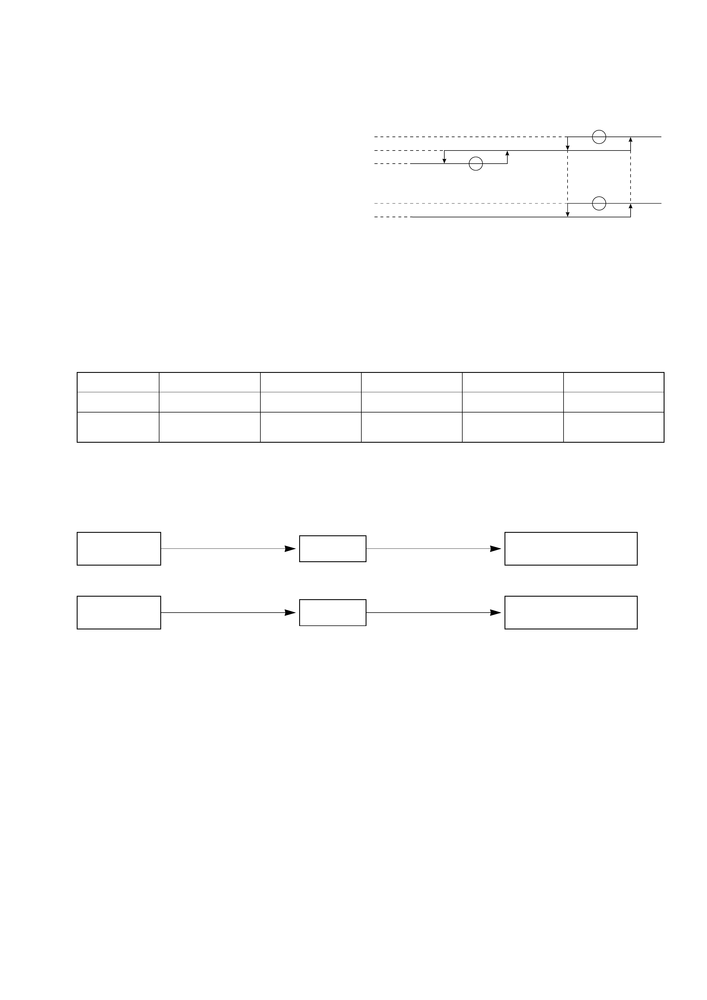
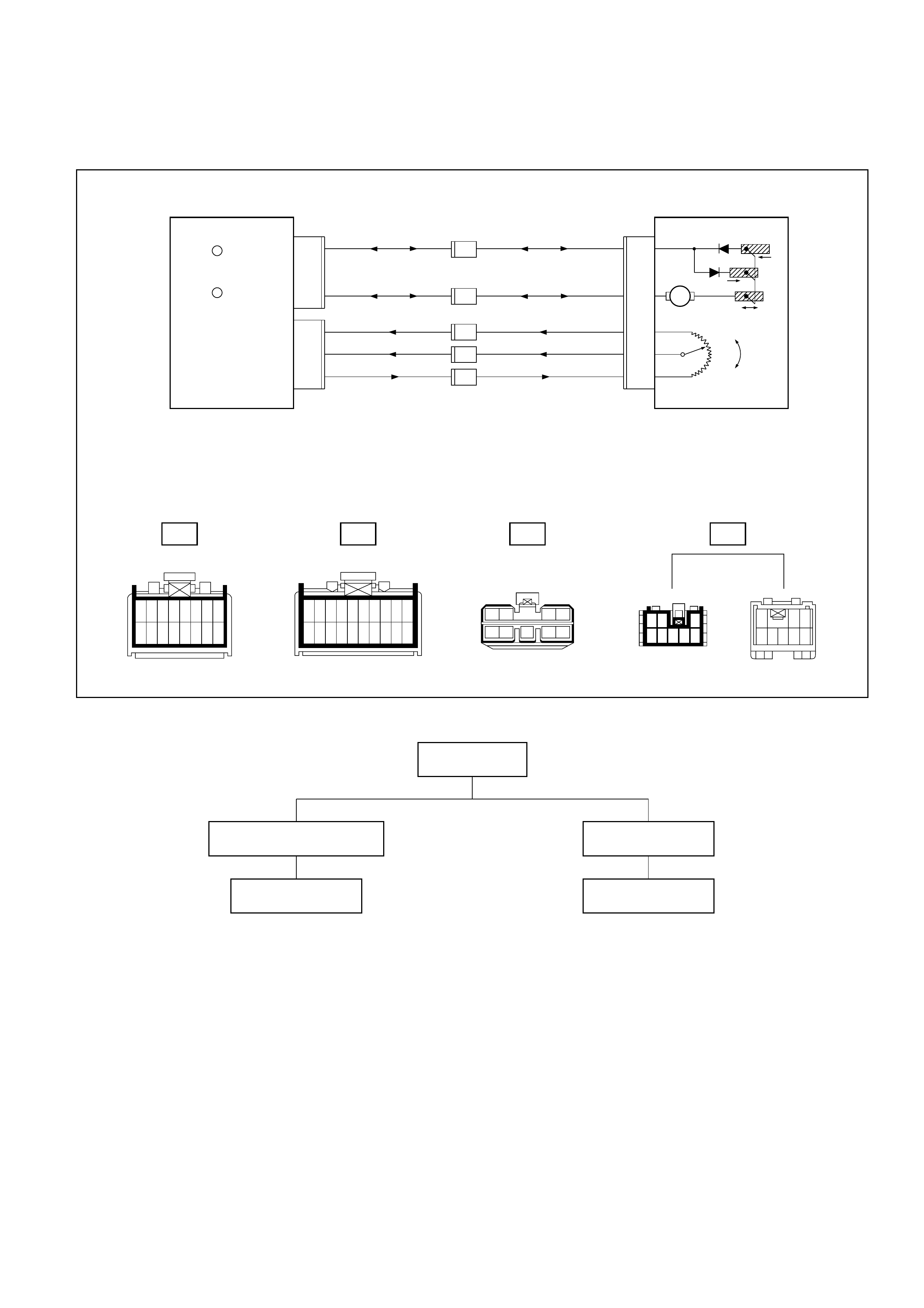
Check of Auto Amplifier (Automatic air conditioner control unit) Power Supply System
•This check is required because a trouble on the auto amplifier (control unit) power supply circuit or
grounding circuit prevents accurate troubleshooting.
Check of auto amplifier
power supply circuit and
grounding circuit.
Chart A
B-18
FL-1 Main
80A
0.5G/R
16
10
7
8
I-32
I-32
C-16
10A
0.3R/W
0.5BR
Backup
Power supply (12V)
Unit ground
Automatic heater/air conditioner control unit
B-18 B-36 H-14
C-20
10A A/C
Relay:
Heater and air
conditioner
0.5B
1.25B
2B
Lighting switch
Lighting switch
H-14 1H-26 9
H-26 14
H-27 20
H-16 14
2
1
4
3
B-36
12
34
H-16
H-26 H-27 I-32
1
2
1
2
109876 54321
2221201918 151413121117 16
12345
1112131415
678910
181920212216 17
101112131415
12345
17181920
6789
16
9876
20191817 16
5
1415
4
13
3
12
2
11
1
10 20
12
19
11
18
10
17
9
16
8
15
7
14
6
13
5
12 34 43 21
12111098765
1314151617181920 12345678
9 10111213141516
D08RY00175
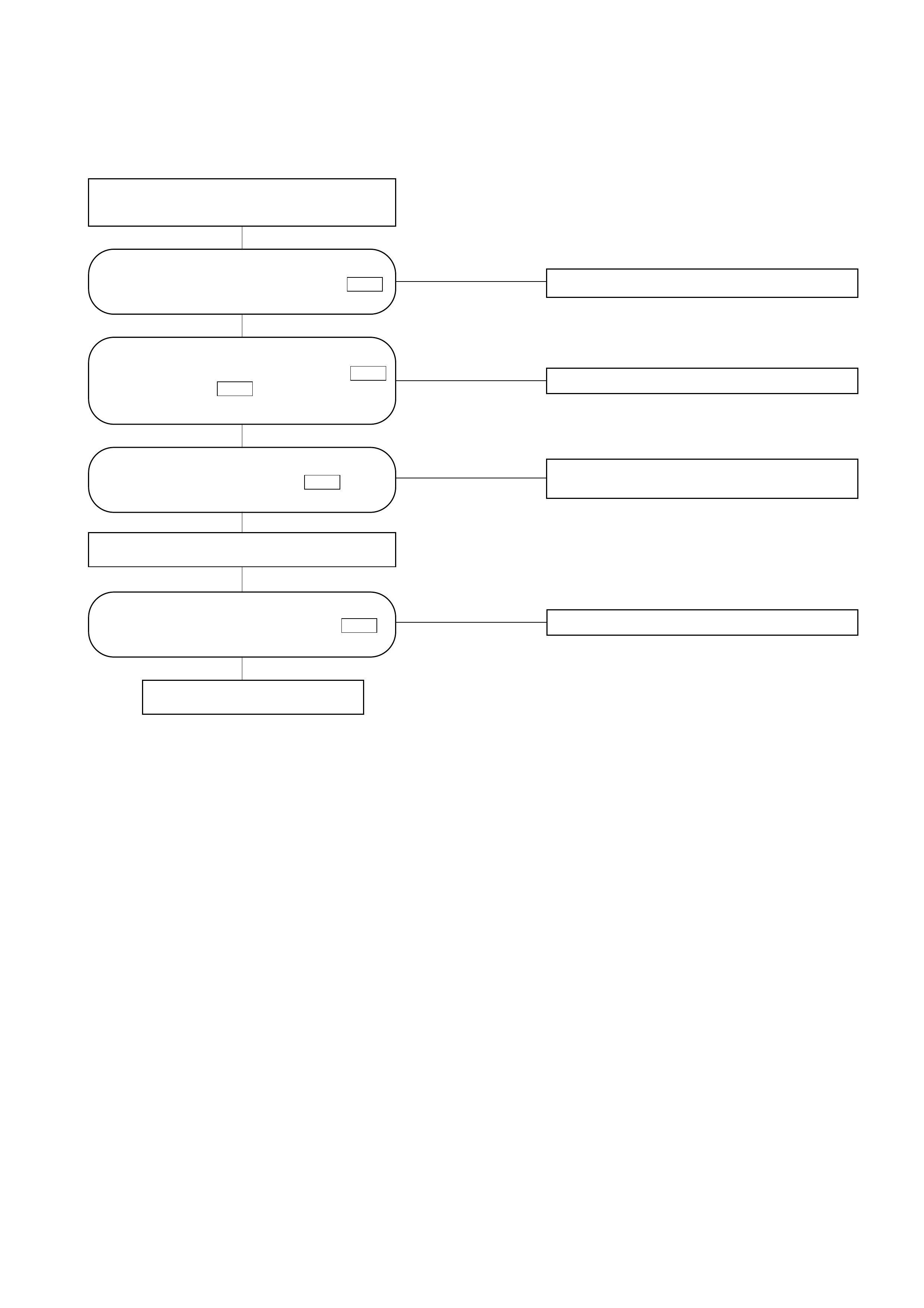
Chart "A" : Check of Auto Amplifier Power Supply System
NO Harness disconnection or improper grounding.
NO Harness disconnection or improper grounding.
NO Harness disconnection or trouble on lighting
switch.
NO Harness disconnection or improper grounding.
Turn off ignition switch.
Power supply system is free of
trouble.
YES
YES
YES
YES
Is battery voltage present between chassis
harness connector terminal No.7
and ground? I-32
Is battery voltage present between
chassis harness connector No.8
and ground? I-32
Are chassis harness connector No.16
and body ground conducted?
B-18 I-32
Turn on ignition switch (engine is started).
Turn on lighting switch.
Is battery voltage present between chassis
harness connector No.10 and
ground? I-32

Performance and Movement checklist for Automatic Air Conditioner Related Parts
Start the engine, and when the engine coolant reached 60°C check performance and movement of the
related parts according the following checklist.
1. Performance Check Using the Manual Switch
Checking Approach
No. Item Acceptance criteria
Condition Operation
Blowing
temperature
(check movement
of air mix door)
Airflow volume
(check movement
of the mode door)
Set temperature to
25.0°C. (1) Turn the fan knob
off.
(2) Turn the fan knob
from LOW to HI.
(1) The fan shall be stopped, thus
stopping air blow, too.
(2) Airflow volume shall change
from LOW to HI.
Blowing
temperature
(check movement
of the mode door)
Set temperature to
25.0°C.
Set the fan knob to HI.
Press the mode switch
to change the blow port
mode sequentially from
the VENT through BI-
LEVEL, FOOT up to
DEF.
LED corresponding to each mode
shall be turned on and the blow
port mode shall be switched
smoothly.
The
interior/outside air
switching mode
(check movement
of intake door)
Set temperature to
25.0°C. Turn the LED off using
the interior/outside air
switch (this introduces
the outside air intake
mode). Then, the set
fan knob to HI and
press the
interior/outside switch
to turn on the LED.
The LED indication shall be
switched from OFF to ON
accompanying a change in air
blowing sound.
Compressor Set the temperature to
FC. (Outside air
temperature is 0C or
above and interior
temperature at ordinary
temperature.)
Press the "OFF" switch.
(1) Press the Auto
switch.
(2) Press the Air
Conditioner switch.
(1) As the fan knob is set to the
Auto position, the A/C switch
LED shall come on and the
compressor shall be turned on.
(2) As the A/C LED comes off, the
compressor shall be turned off.
Auto switch must be
turned on
(FAN-AUTO
MODE-AUTO)
(1) Select FC for the
setup temperature.
(2) Select FH for the
setup temperature.
→Then, select the
MAX Control.
(1) Cold air shall be blown out.
(2) Hot air shall be blown out.
1
2
3
4
5
Checking Approach
No. Item Acceptance criteria
Condition Operation
Change the
temperature gradually
starting with 20°C up to
30°C.
The following phenomena shall be
recognized.
•Temperature of blown air: Cold
air is changed to hot air.
•Change in the air flow volume.
•The blow port mode LED
indication changes in the
following sequence:
Select FH for the
temperature.
Cold air shall be blown out.
The following LEDs shall come on.
• Blow port mode :
• Fan speed: Max Hi
Select FC for the
temperature.
The LED shall come on.
Cold air shall be blown out.
The following LEDs shall come on:
• Blow port mode :
• Intake mode
• Fan speed : MAX Hi
• A/C
1 Full Auto function FAN KNOB “AUTO”
MODE SW “AUTO”
2. Check of Full Auto Function
(VENT) (FOOT)(BI-LEVEL)
F01RX003
F01RX002
F01RX004
TROUBLESHOOTING WITH SELF-DIAGNOSIS FUNCTION
1. Overview of Self-Diagnosis Function
The self-diagnosis is implemented in 3 steps for each target. For detail of check procedure contained in
each step, refer to the relevant section of "Check Procedure by Failed Location" listed in the Self-
Diagnosis Operation Procedure.
For turning on the self-diagnosis function and switching of the check step, refer to the flow chart given
below. You can reset the self-diagnosis function by turning the ignition switch off or turning the DEF
switch on for 3 seconds.
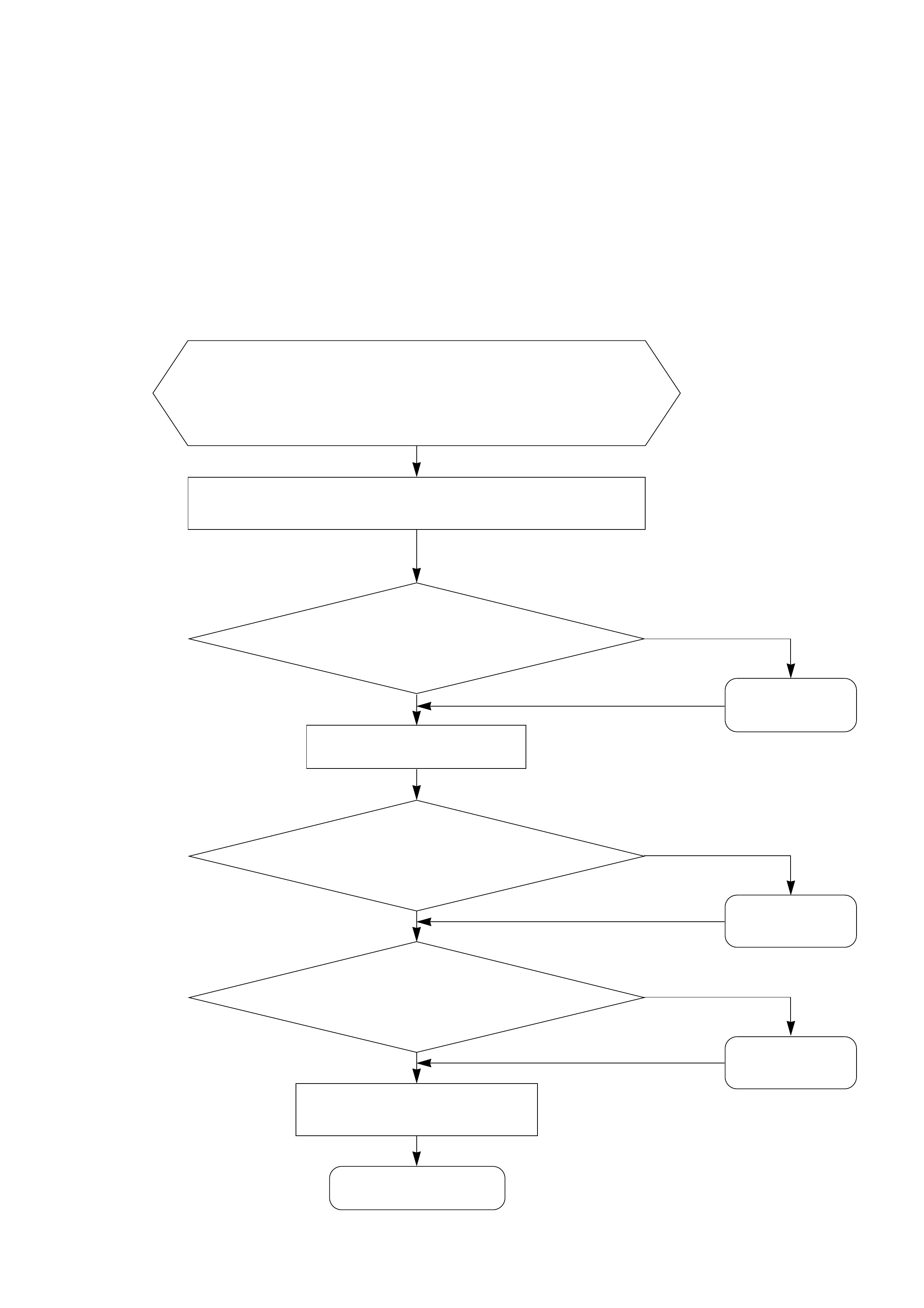
2. Self-Diagnosis Operation Procedure
While holding both the Auto switch and the DEF switch on the
automatic heater/air conditioner panel, turn the IG off and then
on.
<Current trouble diagnosing function is turned on>
Does the A/C LED flash every 0.5 second interval?
Press the A/C switch once. (The past trouble
diagnosing function will
be turned on.)
<Past trouble diagnosing function is turned on>
Does the A/C LED flashes every 0.5 seconds?
<Check of output equipment>
Does each output equipment functions normally according to
operation of the temperature setting lever?
Press the DEF switch for 3
seconds consecutively or turn on
and off the IG.
Failure on the
output equipment
or the harness.
Preparations
(1) Set the IG to the OFF mode.
(2) Apply 60W bulb light to the sun sensor.
(3) Set the temperature setting lever on the automatic heater/air
conditioner panel to the center position (25C).
(4) Set the fan switch on the same panel to the Auto position.
End of the self-diagnosis.
(The current trouble diagnosing function will be turned on
approximately in 10 seconds.)
YES
NO
YES
NO
NO
YES
Refer to *1.
Refer to *2.
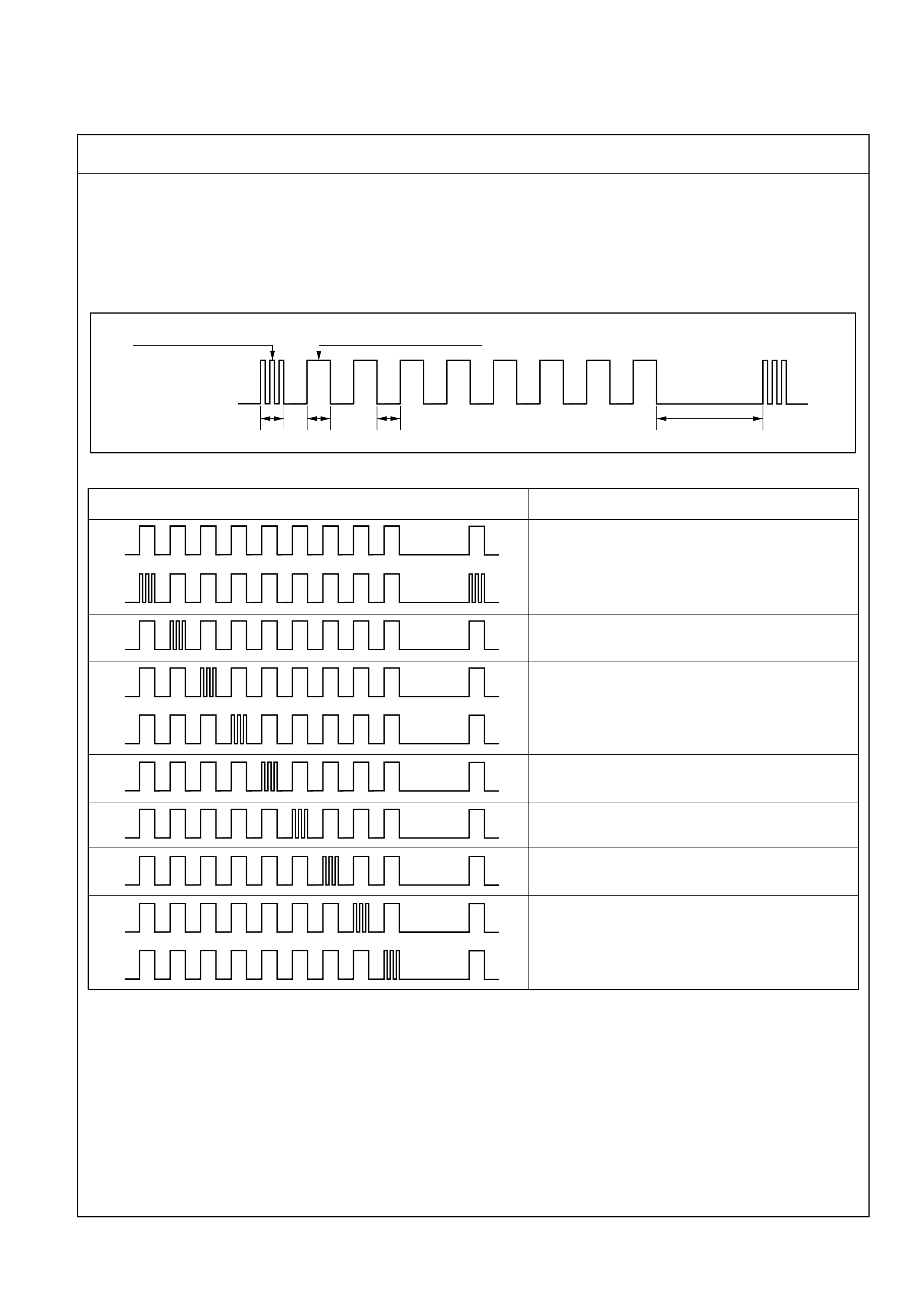
*1. Displaying the Current Trouble Diagnosing Table
Start the engine while holding down both the Auto switch and the DEF switch on the control panel, and
the table will appear in approximately 10 seconds to the indicator lamp (LED) of the air conditioning
switch. Result of the diagnosis along the following 9 items will be shown one by one in 0.5 second
interval irrespective of presence or absence of a trouble for a given item. When the display 9 items is
completed, it is repeated with 3 seconds of interval in between. A failed item is indicated by flashing of
the LED that is repeated 3 times within 0.5 seconds. If a trouble is indicated, you can locate the failed
section by knowing when in the total sequence it has been displayed.
Items for Current Trouble Diagnosis
As shown above, display of result along nine items is repeated with 3-second interval in between.
Note 1: When checking the solar radiation sensor, apply sufficient light using a 60W bulb.
Otherwise, it can be diagnosed as failed.
Note 2: If the temperature setting lever is set on both ends (one set to 18°C, blue scale = Full cool and
the other to 31°C, red scale = Full hot), they can be diagnosed as failed.
Note 3: Likewise, the fan switch can be diagnosed as failed if set on both ends.
LED on
LED off
Indication for presence
of a trouble Indication for normal state
0.5 0.5 0.5 3 seconds interval
ON
OFF
Display pattern Failed part
Normal pattern
In car sensor
Ambient sensor
Sun sensor (Note 1)
Duct sensor
Temperature control lever (Note 2)
Fan switch (Note 3)
Mix actuator
Mode (blow port) control
Intake (fresh air/interior air switching) control
F01RX010
F01RY00008
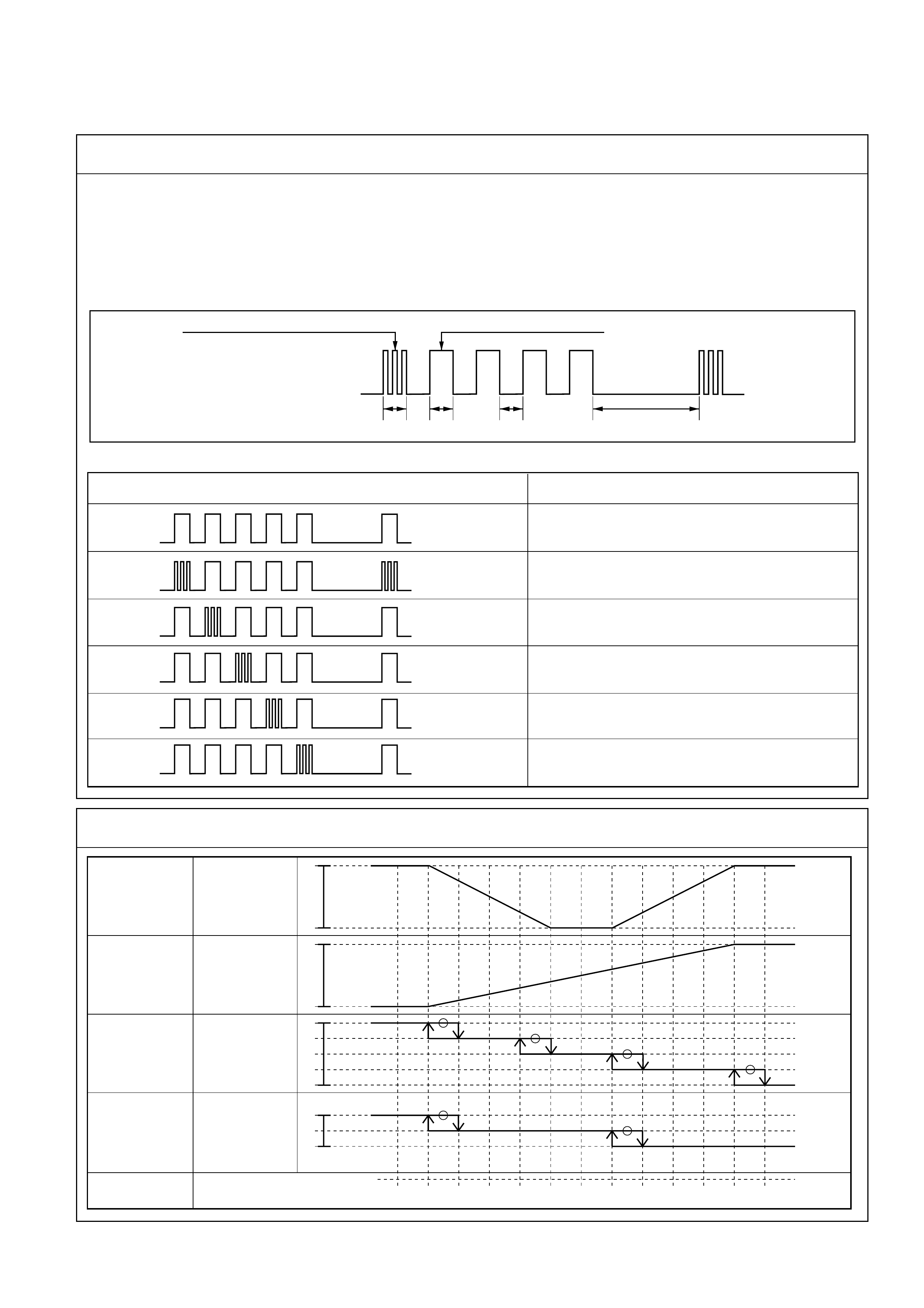
*2. Displaying the Past Trouble Diagnosing Table
The past trouble diagnosis displays only the items on which trouble has recurred 16 times in the past.
If you press the air conditioning switch once while the current trouble diagnosis is taking place, display
of the past trouble diagnosis will appear on the indicator lamp (LED) of the air conditioning switch.
Results of the diagnosis along the following five items are displayed one by one in 0.5 second interval
irrespective of presence or absence of a trouble. A failed item is indicated by flashing of the LED that is
repeated 3 times within 0.5 seconds. You can locate the failed section by counting in what sequence it
has been displayed.
Items for Past Trouble Diagnosis
LED on
LED off
Indication for presence of a trouble Indication for normal state
0.5 0.5 0.5 3 second interval
Display pattern
ON
OFF Normal pattern
In car sensor
Ambient sensor
Sun sensor
Duct sensor
Mix actuator
Failed part
F01RX011
F01RY00007
*3. Check of Output Equipment
FAN
MIX
MODE
DOOR
INTAKE
DOOR
SET UP
TEMPERATURE
100
(%)
33.5
F/H
VENT
B/L
FOOT
D/F
DEF
REC
MIX
FRE
F/C 20 21 22 23 24 25 26 27 28 29 30 F/H
(%)
F/C
F01RY00001
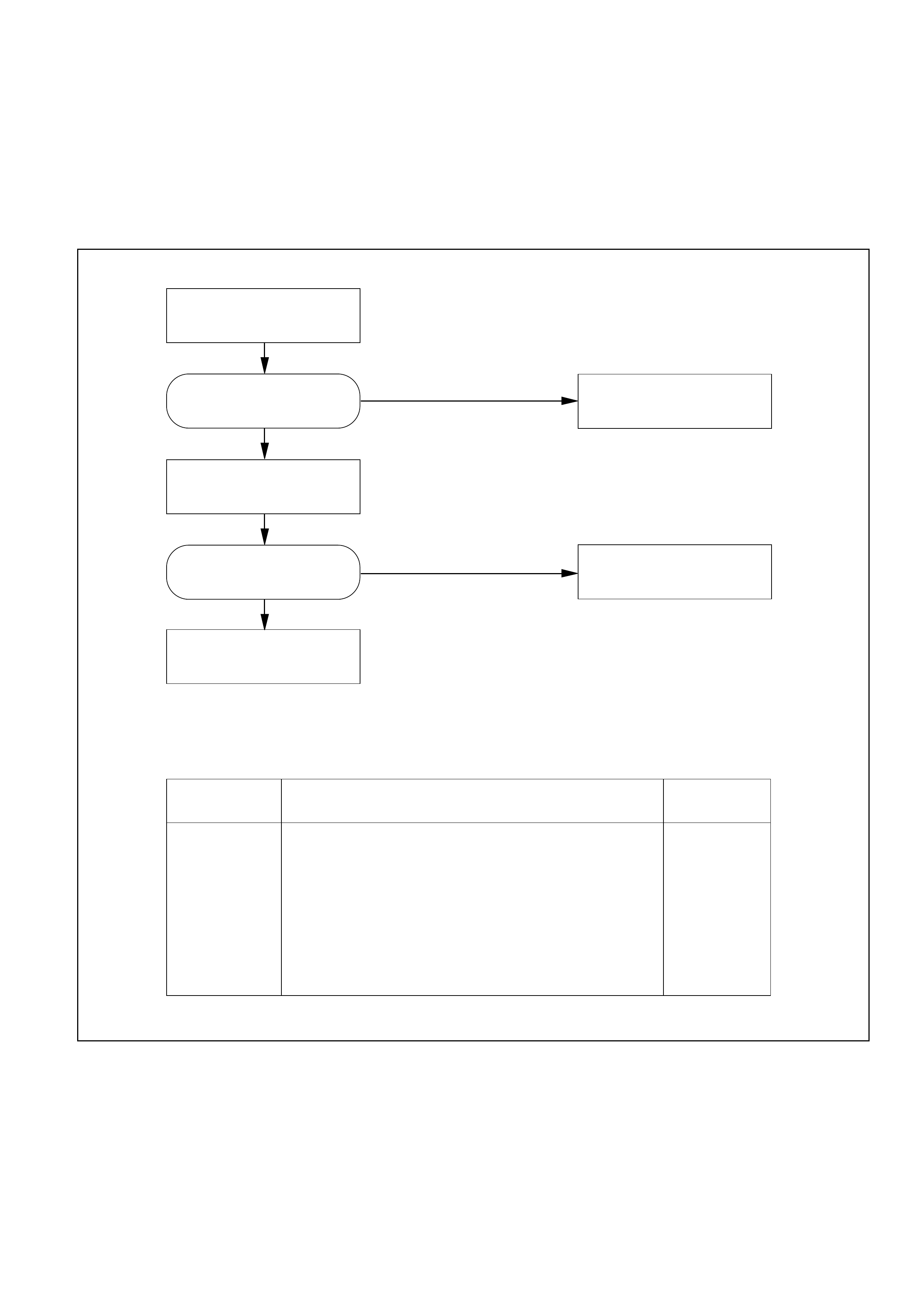
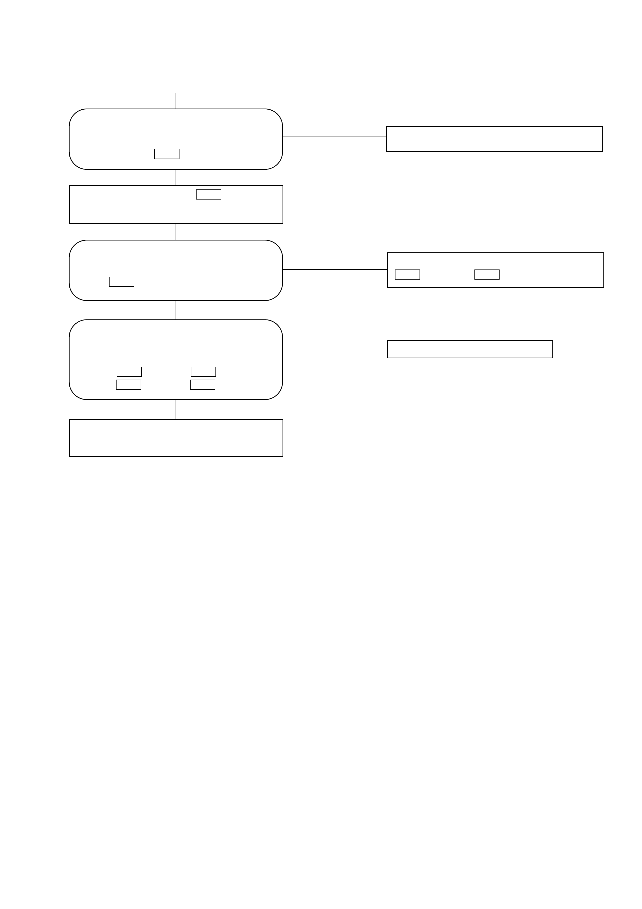
Independent check of sensors
Replace the control unit.
Sensors Allowable range Check method
In car sensor
Ambient sensor
Sun sensor
Refer to the sensor resistance curve.
Refer to the sensor resistance curve.
100 ohms maximum in forward and 0.02 mA
minimum when exposed to 60W incandescent lamp.
Chart 1
Chart 2
Chart 3
Replace the harness and
connector.
Replace the sensors.
Check the related harness and
connector
Normal ?
Normal ?
NO
NO
YES
YES
INSPECTION BY FAILED LOCATION
Inspection of the Sensors
When the self-diagnosis function has determined that trouble is present on the sensors, check them
according to the following flow chart.
F01RY00005
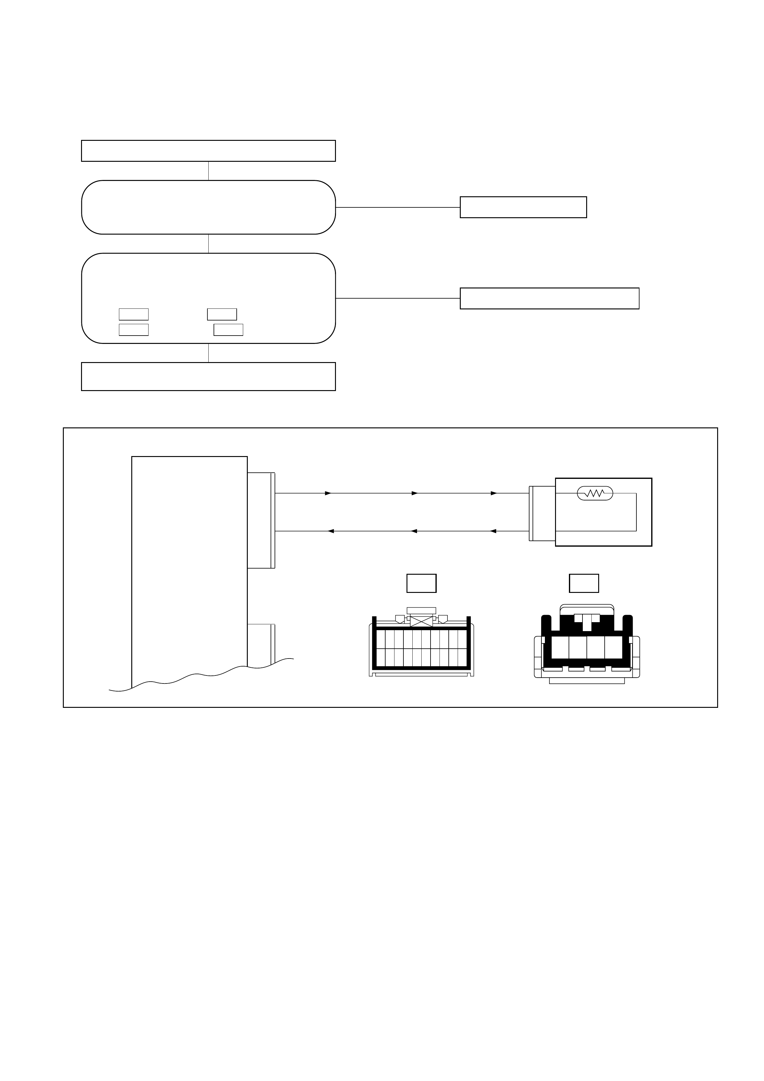
Chart 1: In Car Sensor
NO Replace the sensor.
NO Disconnection of the harness.
Failure on the automatic heater/air
conditioner control unit.
YES
Disconnect the in car sensor connector (I-34).
YES
Is the sensor performance normal? (refer to
the later section on "Check Up")
Are conduction provided between the
following connector terminals on chassis
harness side?:
No.3 and No.1 .
No.4 and No.11 .
I-33I-34 I-33I-34
I-33 I-34
1
11
2
12
3
13
4
14
5
15
6
16
7
17
8
18
9
19
10
20
0.3 BR/B
0.5 B/L
11
1
In car Sensor
Auto A/C Control Unit
(In car Sensor)
(Sensor GND) 4
3
I-33 I-34
12 43
D08RY00174
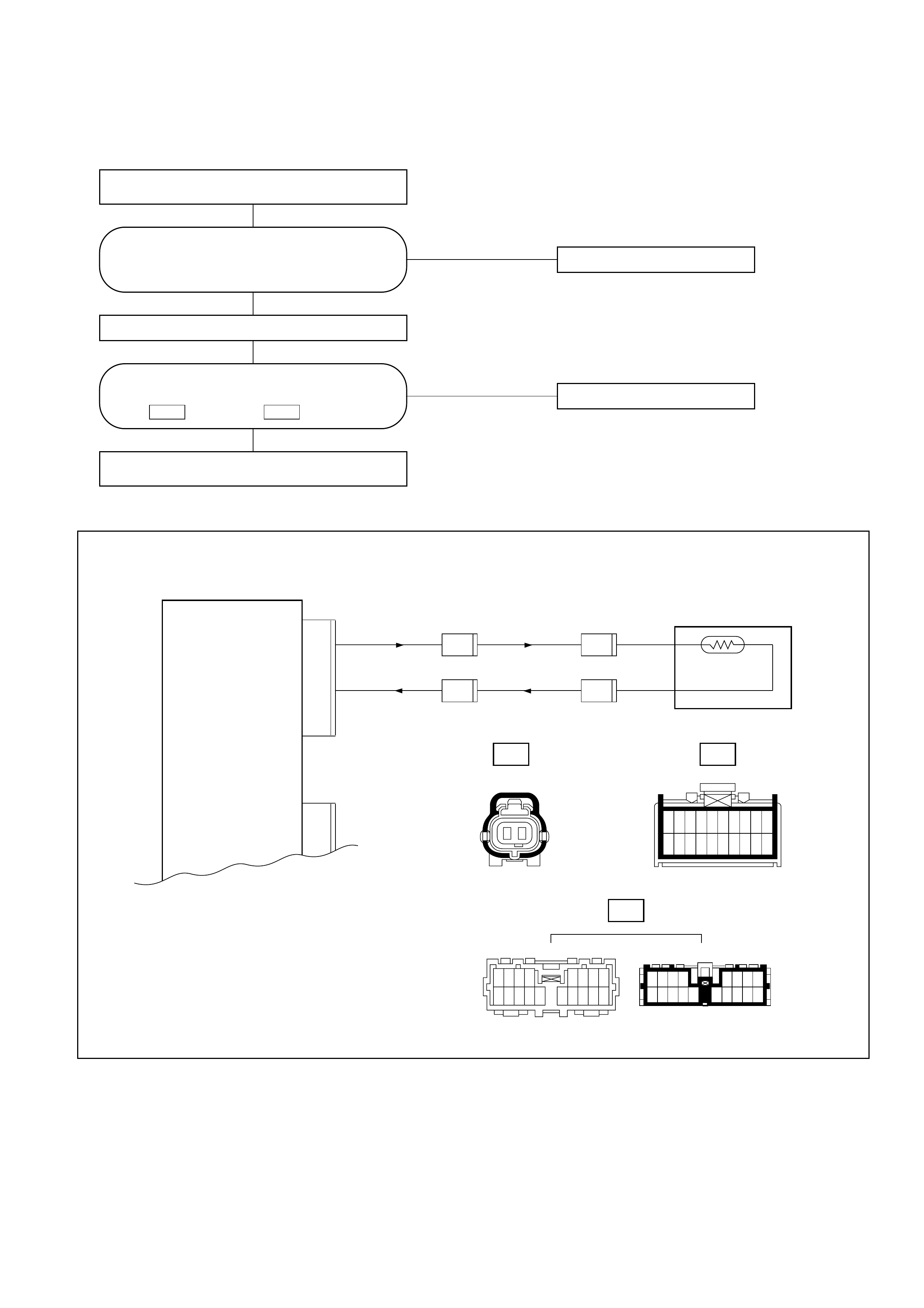
Chart 2: Ambient Sensor
NO Replace the ambient sensor.
NO Failure on the harness.
Connect the ambient sensor connector.
Replace the automatic heater/air conditioner
control unit.
YES
Disconnect the Ambient sensor connector
(C-86).
YES
Is performance of the ambient sensor
normal? (Refer to the later section on
"Check Up".)
Is resistance between the following
connectors normal?
No.2 and No.11 .
I-33I-33
I-33C-86
H-24
1
11
2
12
3
13
4
14
5
15
6
16
7
17
8
18
9
19
10
20
0.3 LG/B
0.3 B/L
11
2
Ambient Sensor
Auto A/C Control Unit
(Ambient Sensor)
(Sensor GND) I-33
0.3 LG/B
0.3 B/L
H-24
8
H-24
9
C-86
1
C-86
2
1718161514
7865
121311109
4132
5678
15161718 14
2341
10111213 9
12
D08RY00176
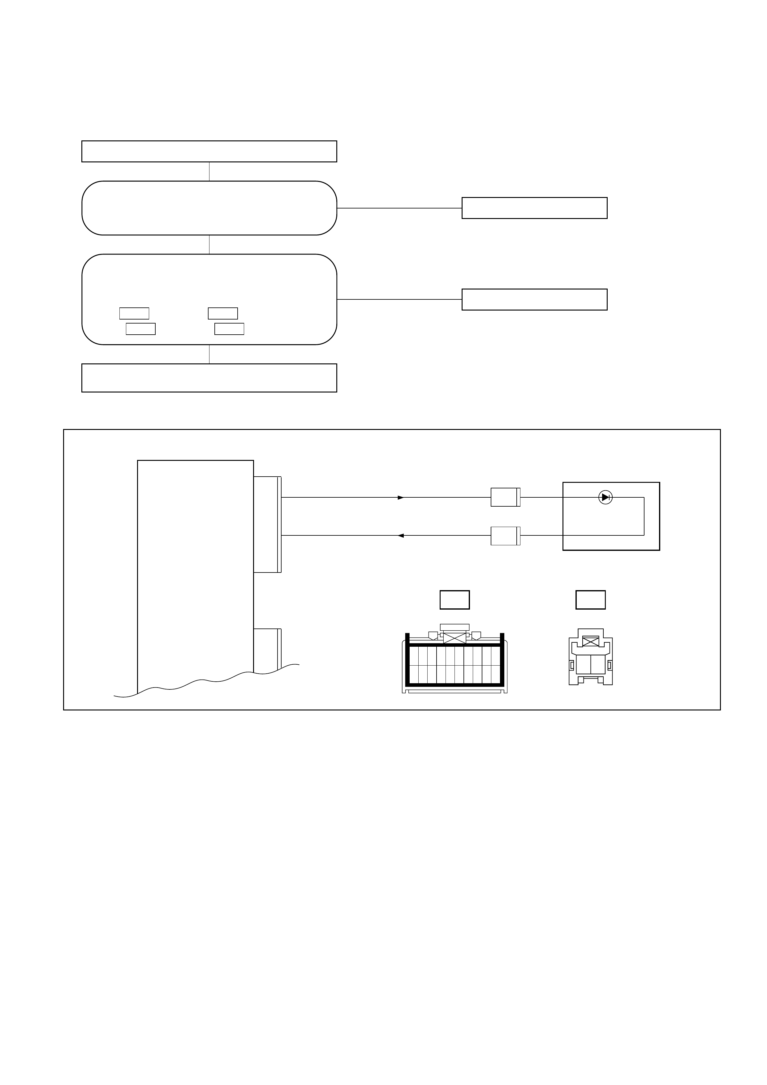
Chart 3: Sun Sensor
NO Replace the sun sensor.
NO Replace the harness.
Replace the automatic heater/air conditioner
control unit.
YES
Disconnect the sun sensor connector (I-35).
YES
Is performance of the sun sensor normal?
(Refer to the later section on "Check Up".)
Is the conduction provided between the
following chassis harness side connector
terminals?
No.3 and No.1 .
No.11 and No.2 .
I-35I-33 I-35I-33
0.3 LG/W
0.3 B/L
11
3
Sun Sensor
Auto A/C Control Unit
(Sun Sensor)
(Sensor GND)
I-33
I-35 1
I-35 2
I-33 I-35
2 1
1
11
2
12
3
13
4
14
5
15
6
16
7
17
8
18
9
19
10
20
D08RY00177
Inspection of the Intake Actuator System
B-19 I-32
B-36
H-26 H-13
I-49I-33
12345678
9 10111213141516
1
11
2
12
3
13
4
14
5
15
6
16
7
17
8
18
9
19
10
20
101112131415
12345
17181920
6789
16
9876
20191817 16
5
1415
4
13
3
12
2
11
1
10
B-36
12
34
M
FL-1 80A
MAIN
11 0.5 L/O
STARTER RELAY
I-33
11
12
13
14
0.3 L/R
0.5 L/W
0.3 B/L
0.3 L/Y
Intake Actuator
Auto A/C Control Unit
BATT.
(Intake Actuator)
GND(COM)
CIRC
FRESH
MIX
I-32
2
1
4
3
0.5 BR0.5 BR3.0 L/R
C-20 10A
A/C
I-49
3
H-13
10
I-49
4
I-49
5
I-49
6
I-49
1
I-49
2
H-26 14
B-19
1
3456
2
3
62
51
4
123
456
Type of the
trouble
Control failure.
Chart B
Does not work at all.
Chart A
D08RY00178
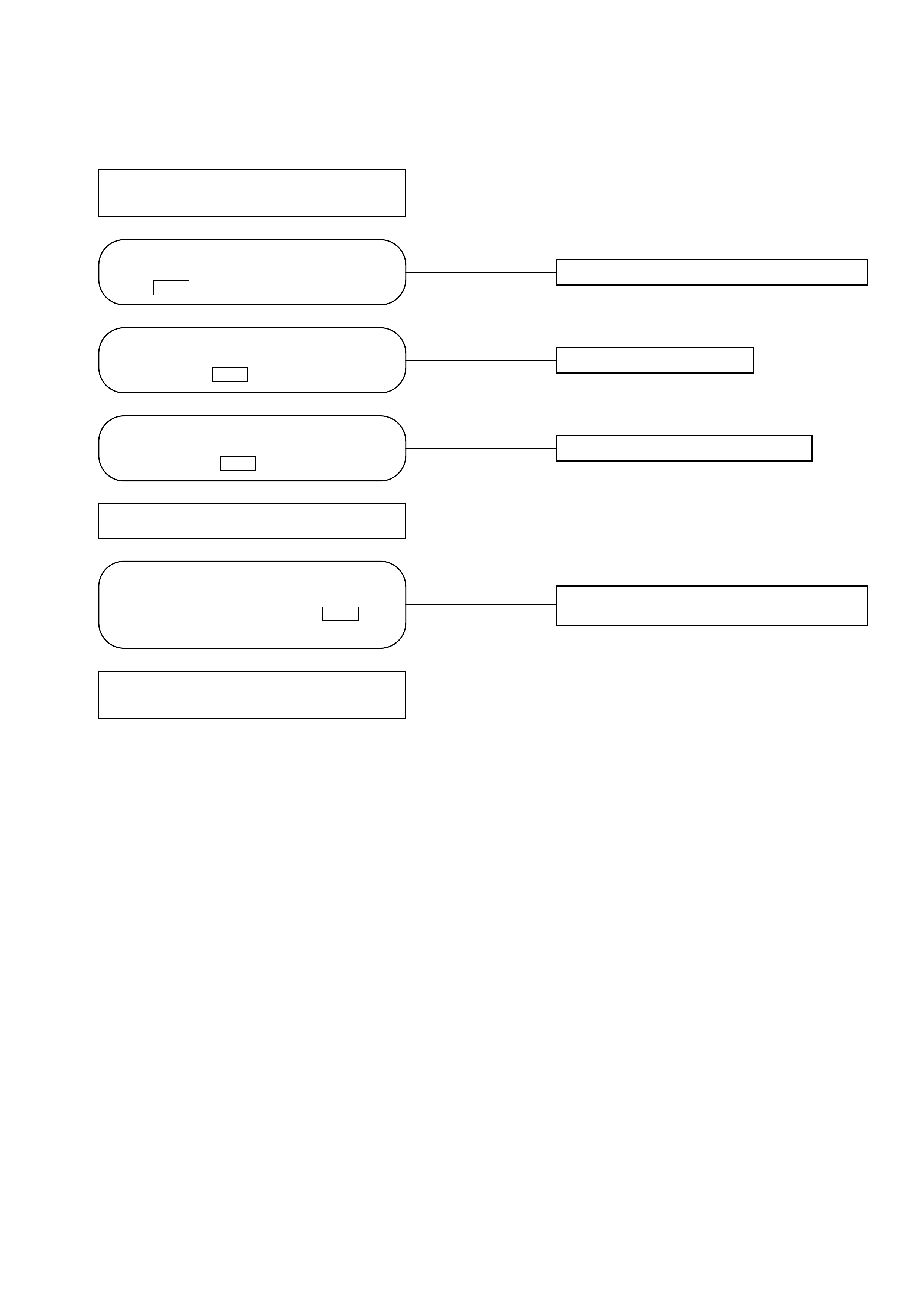
Chart A: Does Not Work At All
NO Failure on the power supply circuit.
NO Failure on the actuator.
NO The harness is disconnected.
NO Replace the automatic heater/air conditioner
control unit.
YES
YES
YES
YES
Turn on the ignition switch (the engine is
started).
Switch between the fresh air intake and the
interior air circulation.
Failure on the intake link unit (intake door
lock).
Is the battery voltage present between the
chassis harness side connector terminal
No.3 and the ground?
I-49
Is the battery voltage present between
the chassis harness side connector
terminal No.4 and the ground?
I-49
Is the battery voltage present between
the chassis harness side connector
terminal No.11 and the ground?
I-32
During the above switch operations, did
the voltage between the chassis harness
side connector terminal No.11 and
the ground go below 0.5V? I-32
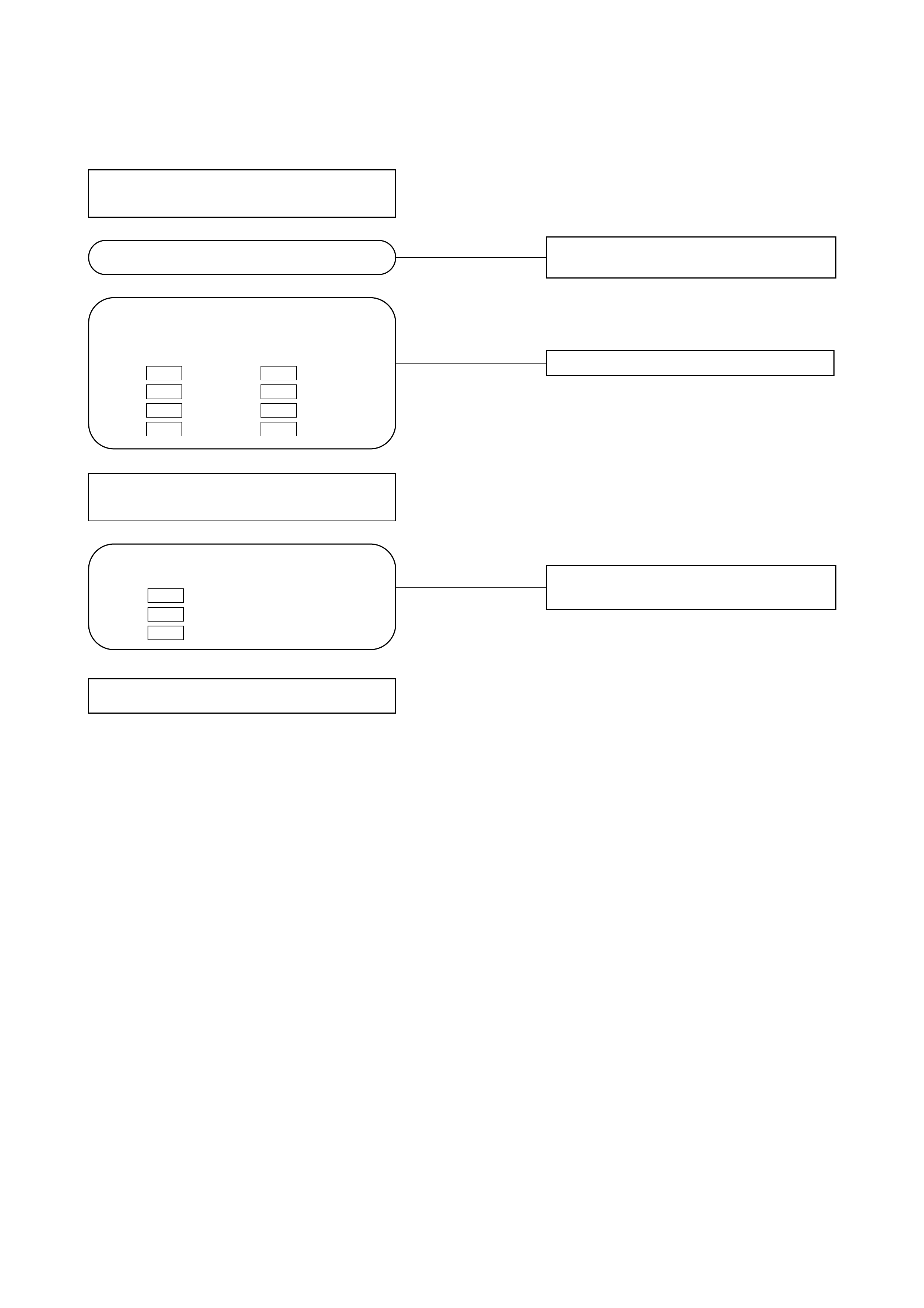
Chart B: Failure on the Intake Control
NO The harness is disconnected.
NO Failure on the automatic heater/air
conditioner control unit.
NO Failure on the automatic heater/air
conditioner control unit.
YES
YES
YES
Turn on the ignition switch (the engine is
started).
Disconnect the intake actuator connector
(I-49).
Failure on the intake actuator.
Is the intake actuator stopped?
Is conduction provided between the
following chassis harness side connector
terminals?
No.5 and No.11 .
No.6 and No.12 .
No.1 and No.13 .
No.2 and No.14 .
I-33I-49 I-33I-49 I-33I-49 I-33I-49
Is voltage (approximately 5V) present
between the following?
No.12 and the ground.
No.13 and the ground.
No.14 and the ground.
I-33
I-33
I-33
Inspection of the Mix Actuator System
H-67I-32 I-33
12345678
9 10111213141516
1
11
2
12
3
13
4
14
5
15
6
16
7
17
8
18
9
19
10
20
I-45
I-32
M
66
0.3 V/W
I-33
11 3
0.5 B/L
57
0.3 V
15 2
0.3 V/G
5
23
20
6
16
24 8
0.3 V/R
I-45
3 KW
Heat
(Potentio Meter)
Cool
CoolHeat
Mix Actuator
Auto A/C Control Unit
HEAT TO COOL
Cool side
Heat side
COOL TO HEAT
GND
(Mix Potentio Meter)
5 V
4
5
8
7
6
0.3 V/W
0.3 B/L
0.3 V
0.3 V/G
H-67
H-67
H-67
H-67
H-67
0.3 V/R
12
56
34
89712 3
8
4567
123
84567
Type of the
trouble
Control failure.
Chart B
Does not work at all.
Chart A
D08RY00179
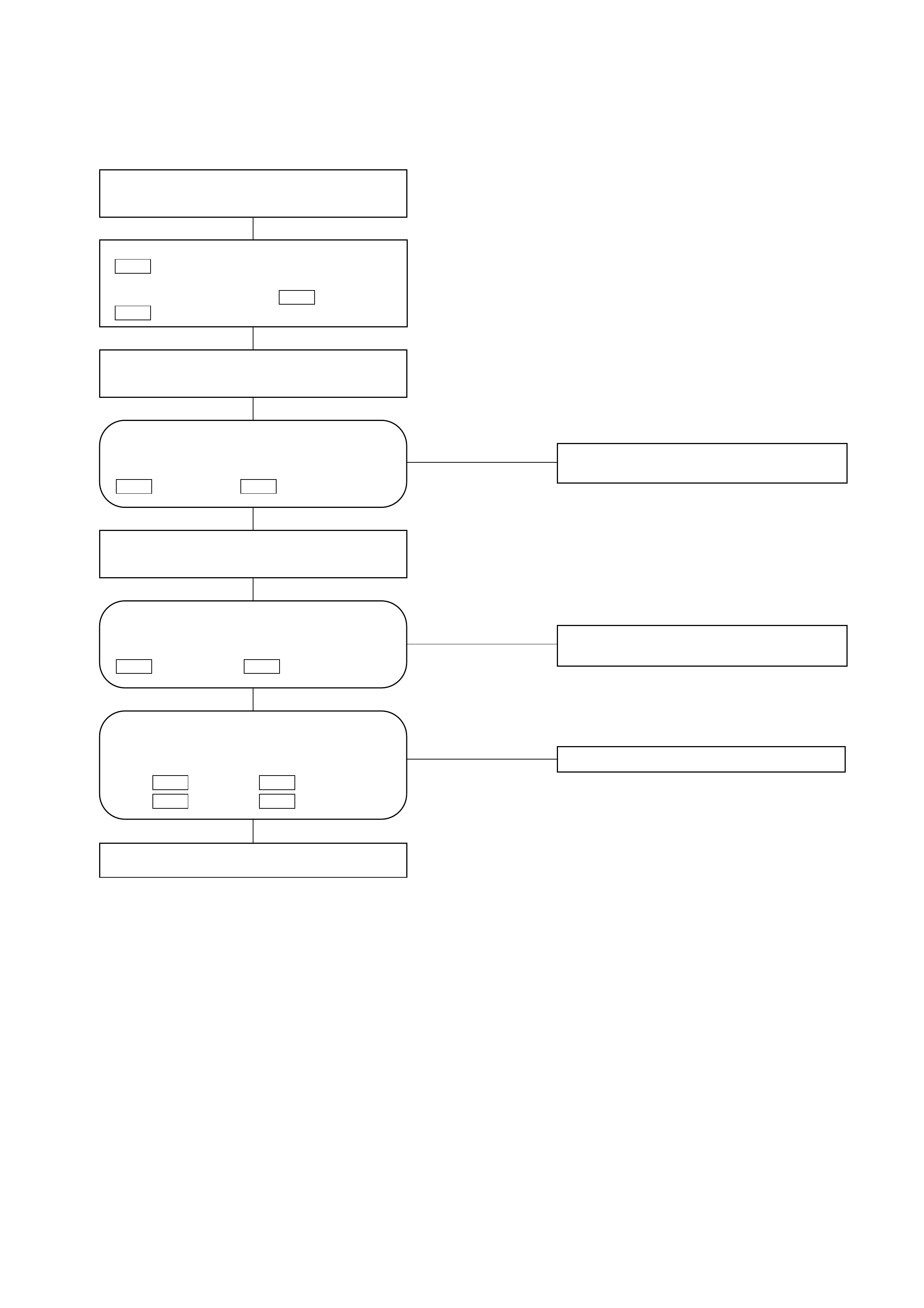
Chart A: Does Not work At All
NO The harness is disconnected.
NO Replace the automatic heater/air
conditioner control unit.
NO Replace the automatic heater/air
conditioner control unit.
YES
YES
YES
Turn on the ignition switch (the engine is
started).
Disconnect the mix actuator connector
.
Short-circuit he chassis harness side
connector terminal No.3 and No.7
.
I-45 I-45
I-45
Using the temperature control lever,
select FC for the temperature.
Using the temperature control lever,
select FC for the temperature.
Failure on the actuator.
Is the battery voltage present on a regular
interval basis between the chassis
harness side connector terminals No.6
(+) and No.5 (-)?
I-32I-32
Is conduction provided between the
following chassis harness side connector
terminals?
No.6 and No.6 .
No.5 and No.8 .
I-45I-32 I-45I-32
Is the battery voltage present on a regular
interval basis between the chassis
harness side connector terminals No.6
(-) and No.5 (+)?
I-32I-32
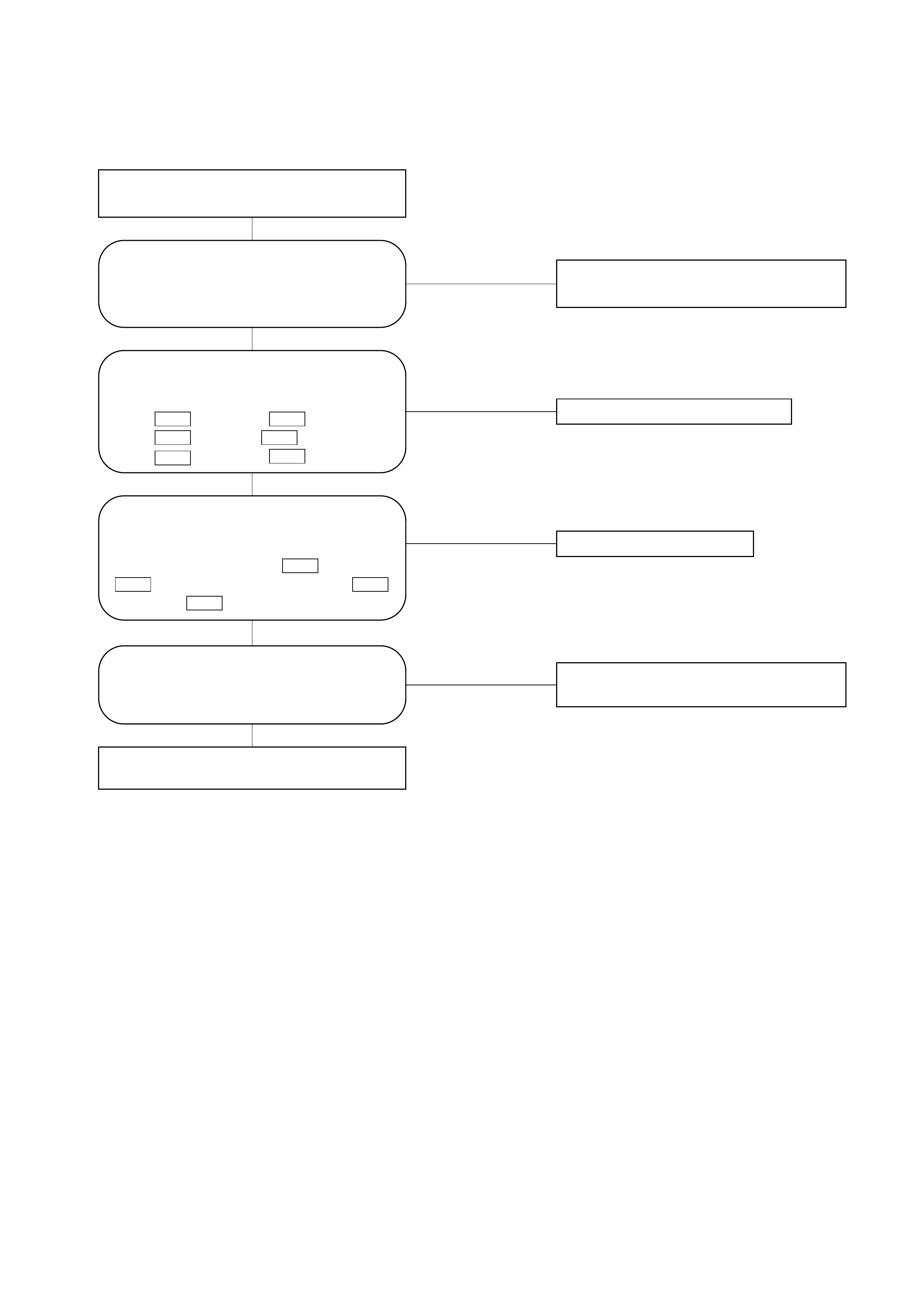
Chart B: Mix Actuator Control Failure
NO Replace the actuator.
NO The harness is disconnected.
NO
NO Mix actuator control failure due to the
failed sensor.
YES
YES
YES
YES
Turn on the ignition switch (the engine is
started).
Replace the automatic heater/air conditioner
control unit.
Is conduction provided between the
following chassis harness side
connector terminals?
No.3 and No.11 .
No.7 and No.5 .
No.2 and No.15 .
I-33
I-45 I-33I-45 I-33I-45
Is sum of the voltages between the
following chassis harness side connector
terminals approximately 5V?
Voltage between No.15 and No.5
plus voltage between No.5
and No.11 .
I-33 I-33I-33 I-33
Does the self-diagnosis function (the
current trouble display) indicate failure
on the mix actuator potentiometer?
Is full stroke of the air mix door available
when you selected FH or FC using the
temperature control lever? Failure on the air mix door or the link
unit.
Inspection of the Mode Actuator System
H-26
101112131415
12345
17181920
6789
16
9876
20191817 16
5
1415
4
13
3
12
2
11
1
10
H-25
I-32 I-33
12345678
9 10111213141516
1
11
2
12
3
13
4
14
5
15
6
16
7
17
8
18
9
19
10
20
I-32
0.3Y/BR 0.3Y/BR
B-69
I-33
10
9
8
7
11
6
3
DEF TO VENT
VENT side
DEF side
MODE1
MODE2
MODE3
MODE4
MODE5
S.GND
4
1
2
3
4
20
5
26
25 11
0.5Y/G 0.3Y/G12
0.3GR 0.3GR
0.3GR/G
18
0.5GR/R 0.5GR/R19
0.5GR/G 0.3GR/G5
0.3GR/L 0.3GR/L1
0.5B/L 0.3B/L4
Auto A/C Control Unit
M
1
5
4
3
8
7
2
6
9
VENT
FOOT
DEF
B/L
D/F
Mode Actuator
(Heater Unit)
VENT TO DEF
H-25
H-25
H-26
H-26
H-25
H-26
H-26
0.5B/L 8 H-25
B-69
12
56
34
897
10 9 8 7 6 5 4 3 2 1
2221201918 151413121117 16
12345
1112131415
6 7 8 9 10
181920212216 17
Type of the
trouble
Control failure.
Chart B
Does not work at all.
Chart A
D08RY00180
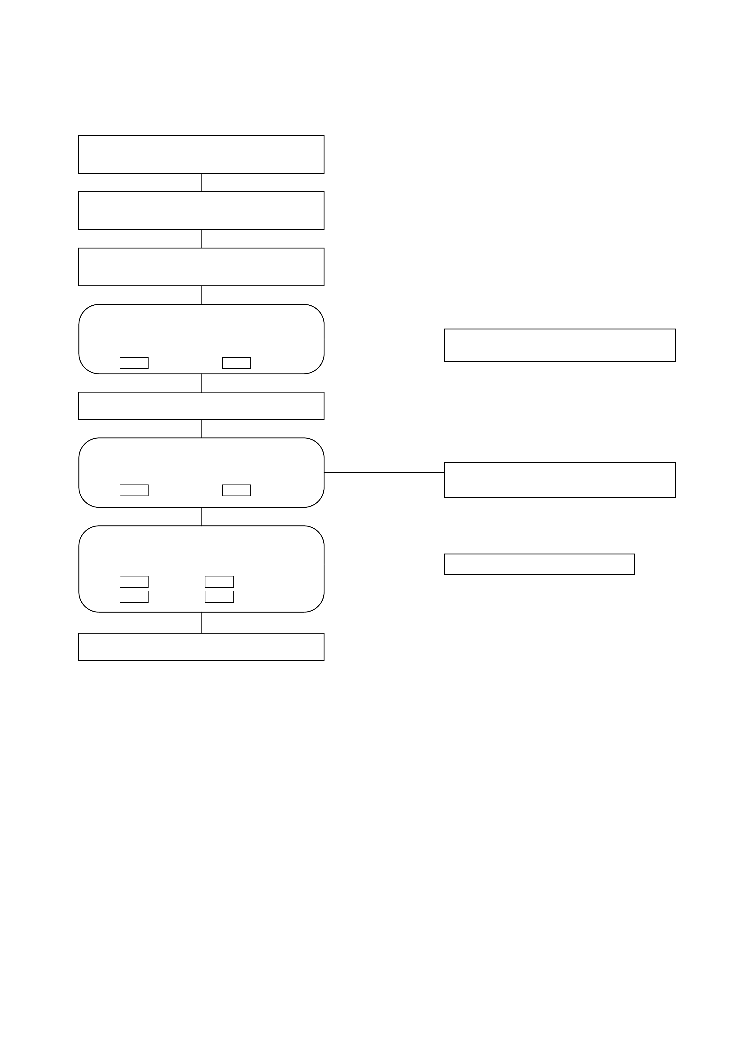
Chart A: Does Not Work At All
NO The harness is disconnected.
NO Replace the automatic heater/air
conditioner control unit.
NO Replace the automatic heater/air
conditioner control unit.
YES
YES
YES
Turn on the ignition switch (the engine is
started).
Disconnect the mode actuator connector
(B-69).
Select VENT pushing the mode actuator
switch.
Turn on the DEF mode switch.
Failure on the actuator.
Is the battery voltage provided on a
regular interval between the following
chassis side connector terminals?
No.3 (+) and No.4 (-).
I-32I-32
Is conduction provided between the
following chassis harness side connector
terminal?
No.1 and No.4 .
No.5 and No.3 .
I-32B-69 I-32B-69
Is the battery voltage provided on a
regular interval between the following
chassis harness side connector
terminals?
No.4 (+) and No.3 (-).
I-32I-32

Chart B: Mode Actuator Control Failure
NO The harness is disconnected.
NO Replace the actuator.
NO Failure on the mode door or the link unit.
YES Mode control failure due to the failed
sensor.
NO
YES
YES
YES
Turn on the ignition switch (the engine is
started).
Replace the automatic heater/air conditioner
control unit.
Is conduction provided between the
following chassis harness side
connector terminals?
No.9 and No.11 .
No.3 and No.10 .
No.4 and No.8 .
I-33B-69 I-33B-69 I-33B-69
Is sum of the voltages between the
following chassis harness side connector
terminals approximately 5V?
Voltage between No.15 and No.1
plus voltage between No.15
and No.11 .
I-33 I-32I-32 I-32
Does the mode work normally through
manual operation?
Is full stroke available from the mode
door when the defrost mode and vent
mode are selected?
Inspection of the Fan Motor System
H-26
101112131415
12345
17181920
6789
16
9876
20191817 16
5
1415
4
13
3
12
2
11
1
10
H-20
I-32 I-33
12345678
9 10111213141516
1
11
2
12
3
13
4
14
5
15
6
16
7
17
8
18
9
19
10
20
B-1 B-5 I-50B-36
12
34
I-33
M
17
19 I-50
2
0.3 GR
2.0L/B
I-50
I-50
1
3
B-5
2
B-5
1
I-51
2
4
1
3
B-1 2.0 B 1
2 B
2 L/B
0.3 BR
0.5 L/B 2 L/B
2 B
0.3 GR/L
12
3.0 L3.0 L/R
C-19 25A
FUSE
C-20 10A
FUSE
Blower Motor
Max High
Relay
Power
Transistor
Auto A/C
Control Unit
B-36
I-51
I-51I-51
I-32
I-33
12
33
14
H-20
H-26
10
1
2
I-51
2
34
1
1
23
H-20 2
2
41
3
1 2
34
D08RY00181
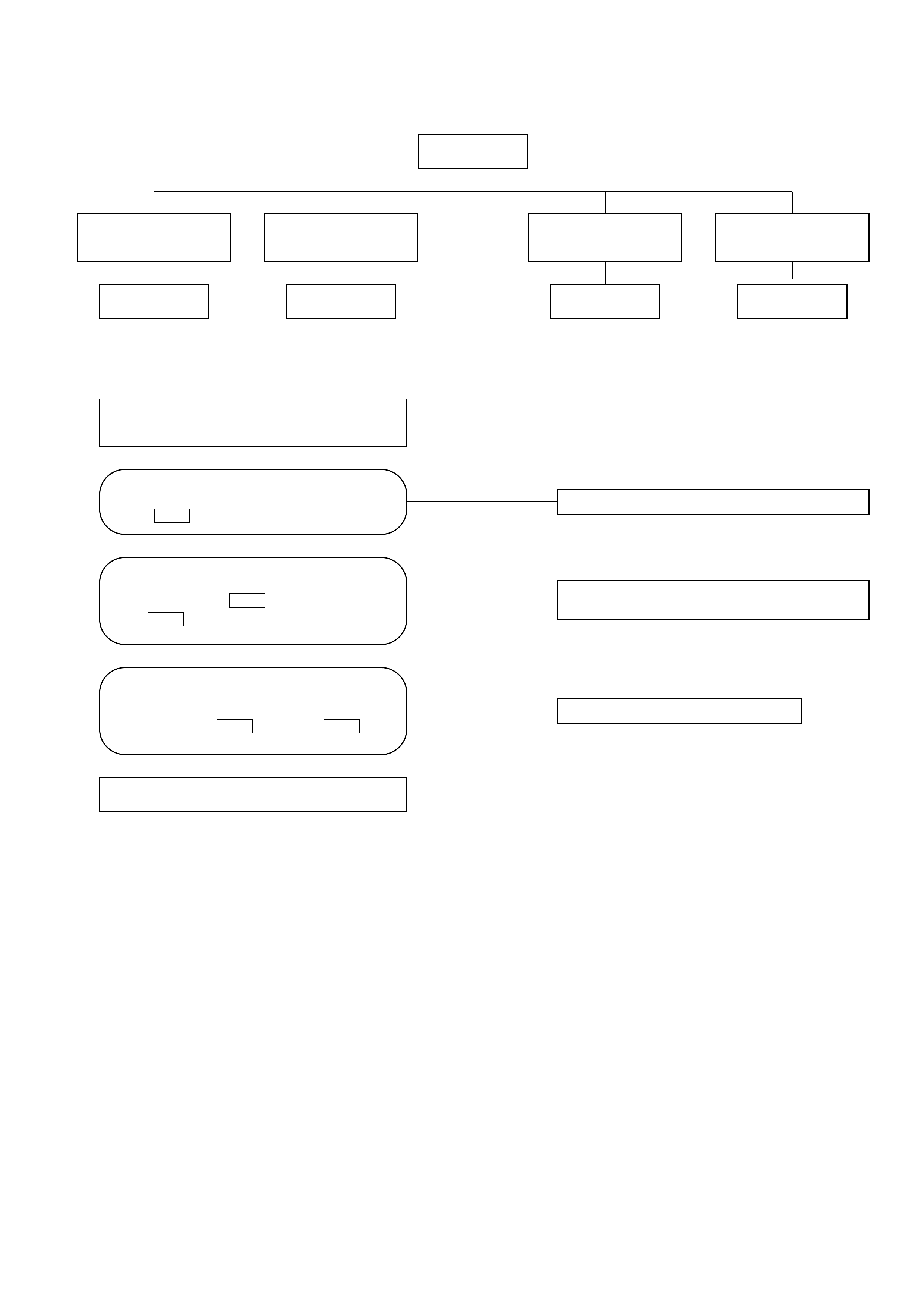
Chart A: Fan Does Not Rotate At All
NO Failure on the power supply system.
NO Failure on the ground or the harness is
disconnected.
NO Replace the fan motor.
YES
YES
YES
Turn on the ignition switch (the engine is
started).
Refer to Charts B and C.
Is the battery voltage present between the
chassis harness side connector terminal
No.2 and the ground?
B-5
Are the chassis harness side connector
terminals No.4 and the ground
(No. ) conducted?
B-1 I-51
Is the battery voltage present between
the chassis harness side connector
terminals No.1 and No.2 ?
B-5B-5
Type of trouble
The fan does not
rotate in any mode
other than MAX HI. The fan does not stop.
Chart B Chart C Chart D
The fan does not
rotate in the MAX HI
mode.
The fan does not
rotate at all.
Chart A
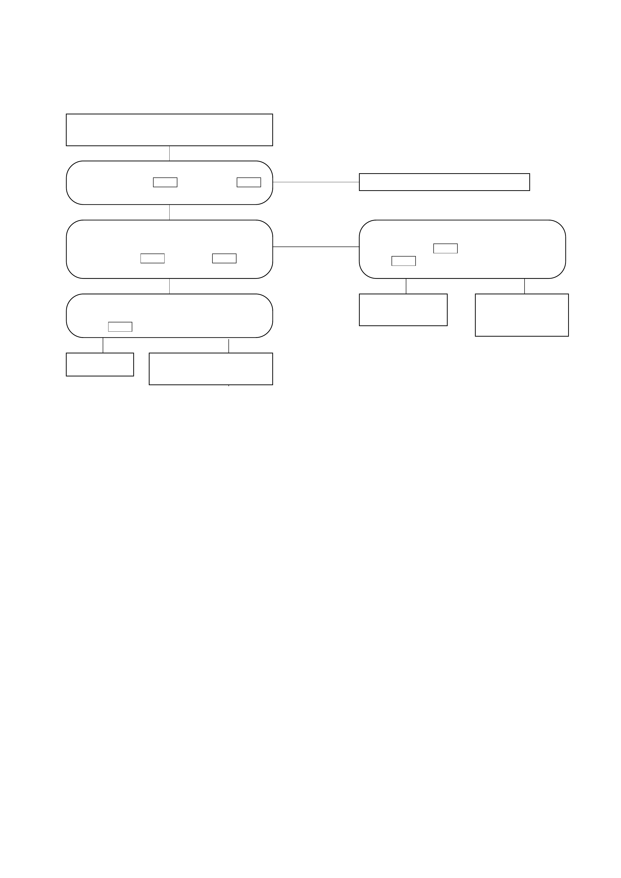
Chart B: Fan Does Not Rotate in MAX HI Mode
NO The harness is disconnected.
YES
NO
NO NO
YES
YES
YES
Turn on the ignition switch (the engine is
started).
Set the fan switch to the MAX HI.
The harness is
disconnected. Failure on the automatic
heater/air conditioner
control unit.
Failure on the MAX
HI relay. Failure on the
ground or the
harness is
disconnected.
Is the battery voltage present between the
chassis harness side connector terminal
No.12 and the ground?
I-32
Are the chassis harness side connector
terminal No.4 and the body ground
(No. ) conducted?
B-1 I-51
Are the chassis harness side connector
terminals No.1 and No.2
conducted? I-51B-5
Is the battery voltage present between
the chassis harness side connector
terminal No.1 and No.3 ?
I-51I-51
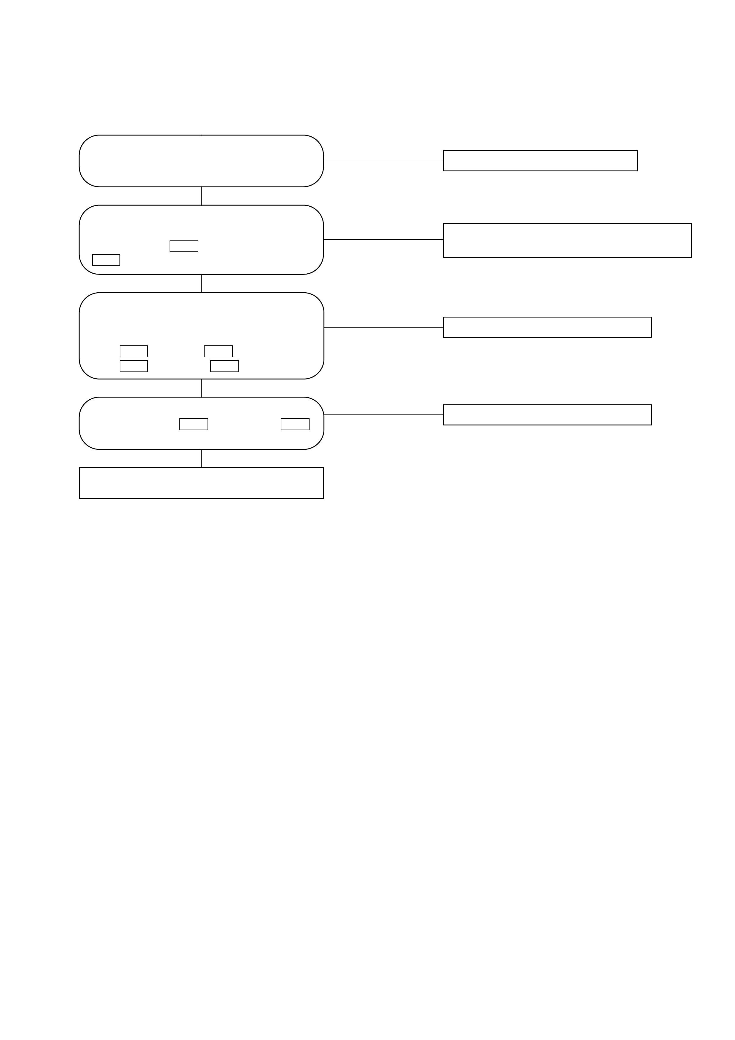
Chart C: Fan Does Not Rotate In Any Mode Other Than MAX HI
NO Replace the power transistor.
NO Failure on the ground or the harness is
disconnected.
NO The harness is disconnected.
NO The harness is disconnected.
YES
YES
YES
YES
Failure on the automatic heater/air
conditioner control unit.
Is the power transistor performance
normal? (Refer to the later section on
"Check Up".)
Is the battery voltage present between
the chassis harness side connector
terminal No.3 and the ground No.
?
B-1 I-50
Is conduction provided between the
following chassis harness side connector
terminals?
No.1 and No.1 .
No.1 and No.17 .
I-33B-5 I-50B-5
Are the chassis harness side connector
terminals No.2 and No.19
conducted? I-33I-50
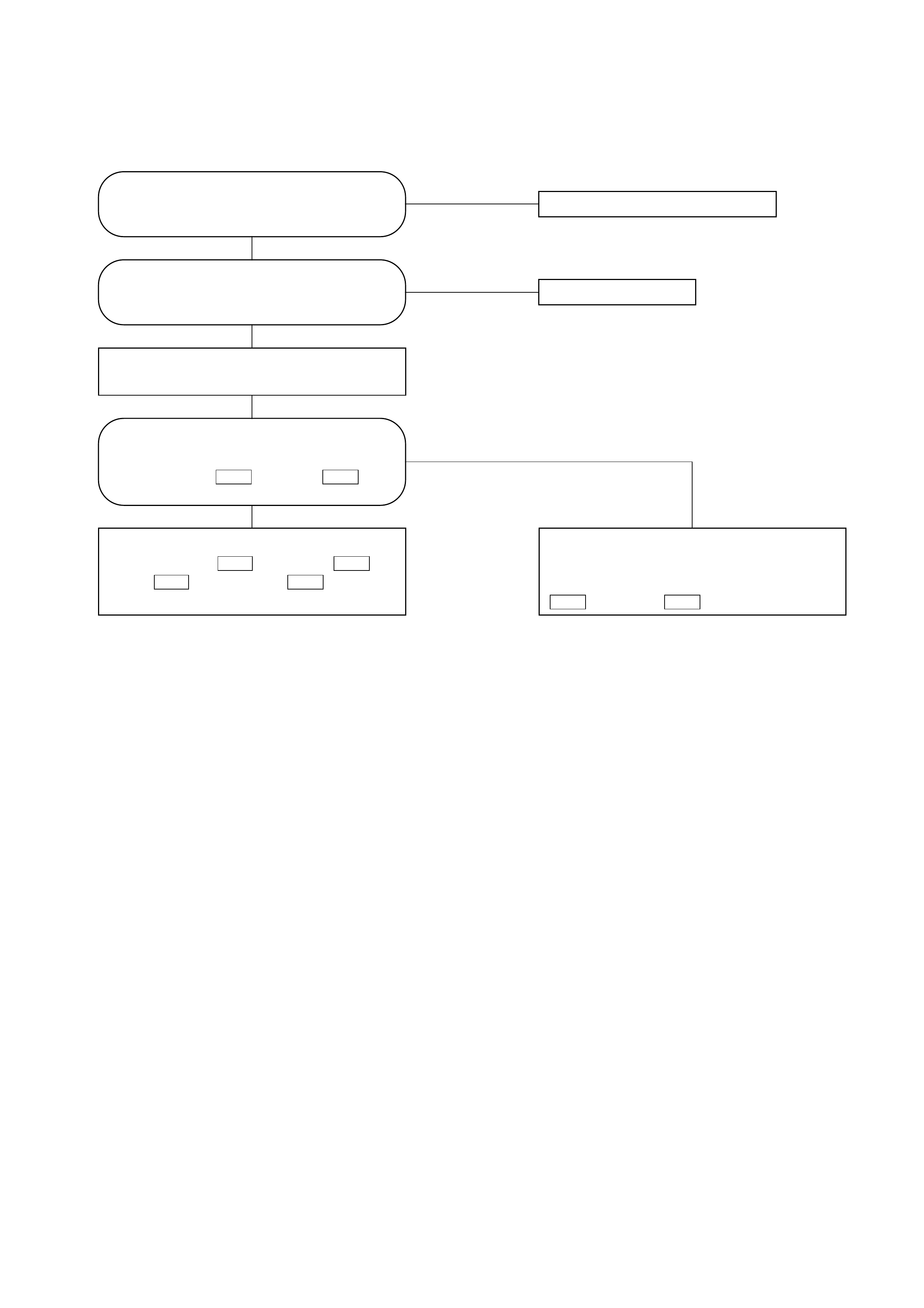
Chart D: Fan Does Not Stop
NO Replace the power transistor.
NO Replace the relay.
YES
NO
YES
Turn on the ignition switch (the engine is
started).
YES
Is the power transistor performance
normal? (Refer to the later section on
"Check Up".)
Is the MAX HI relay performance
normal? (Refer to the later section on
"Check Up".)
Is the battery voltage present between
the chassis harness side connector
terminals No.1 and No.3 ?
I-51I-51
The chassis harness side connector
terminals No.1 and No.2 , or
No.1 and No.1 is short
circuited. I-50B-5 I-51B-5
Failure on the automatic heater/air
conditioner control unit. Or, the harness
line is short circuited between the chassis
harness side connector terminals No.3
and No.12 .
I-32I-51
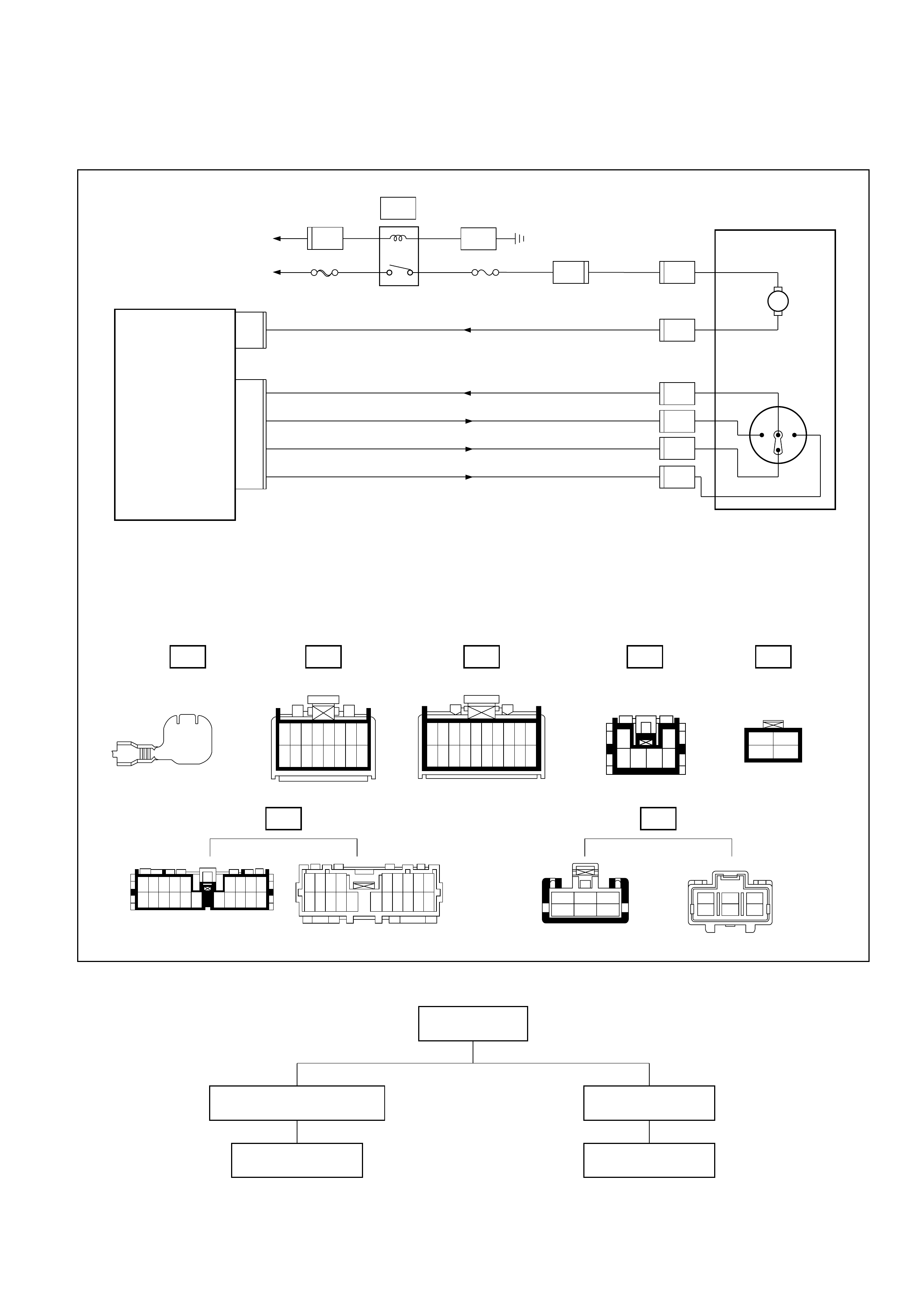
Inspection of the Magnet Clutch System
6VE1 Engine
I-32
C-1 C-3I-33
E-3 E-19
12345678
9 10111213141516
1
11
2
12
3
13
4
14
5
15
6
16
7
17
8
18
9
19
10
20
B-19 C-25
A
2
B-36
1
H-14
C-19
25A
BLOWER
MOTOR
C-20
10A
A/C
FL-1
80A
MAIN
Heater
Relay
1
B-36
10
H-13
0.3
B
0.85
W/G
0.85
W/R
3.0
W
3.0
L/R
0.5
BR
1.25
B
B-19
BODY-LH
3
B-36
4
B-36
BATT.(+)
Blower
Motor Intake
Actuator
STARTER
RELAY(1)
0.5
LG
0.5
BR 0.5
BR
0.5
G/W
0.5
P/G
0.5
P/G
0.5
G/O
0.5
G/O
PCM
(C3-E15)
31 13
COMP-F/B
7
0.5
BR
0.5
BR/Y
0.3
G/B
0.5
G/B
0.5
BR/Y
0.5
BR
Triple
Pressure
Switch 0.5
BR
A
A/C
Thermo Relay
Auto A/C Control Unit
3
X-5
16
H-16 17
H-16
14
I-32
18
I-33
1
X-5
13
H-24
12
H-41
2
1
C-25
C-25
4
X-5 X-5
2
X-5
7
H-16
A/C
Compressor
Relay
Magnetic
clutch
1
X-7
3
X-7 4
X-7
2
X-7
PCM
(C-1-B14)
E-3
9
1
H-6
7
H-41
5
H-41
Engine
Coolant
Temperature
Sensor
ENGINE COOLANT
TEMPERATURE GAUGE
0.5
Y/B 0.5
Y/B
0.5
Y/B
E-19
11
1
H-6
1
H-24
I-33
4
B-36 X-5 X-7
H-14
1
2
1
2
H-16
H-24
H-13
H-6 H-41
12
3412 111
3
62
51
4
123
456
10 9 8 7 6 5 4 3 2 1
2221201918 151413121117 16
12345
1112131415
6 7 8 9 10
181920212216 17
6
H-41
4321
8765
12 11 10 9
16 15 14 13
1234
5678
9101112
13 14 15 16
1718161514
7865
121311109
4132
5678
15161718 14
2341
10111213 9 A1 A2 A3 A4 A5 A6 A7A8 A9
A10A11A12 A13A14 A15 A16
B1 B2 B3 B4 B5 B6 B7 B8 B9
B10 B11 B12 B13 B14 B15 B16
E1 E2 E3 E4 E5 E6 E7 E8 E9
E10 E11 E12 E13 E14 E15 E16
F1 F2 F3 F4 F5 F6 F7 F8 F9
F10 F11 F12 F13 F14 F15 F16
D08RY00182
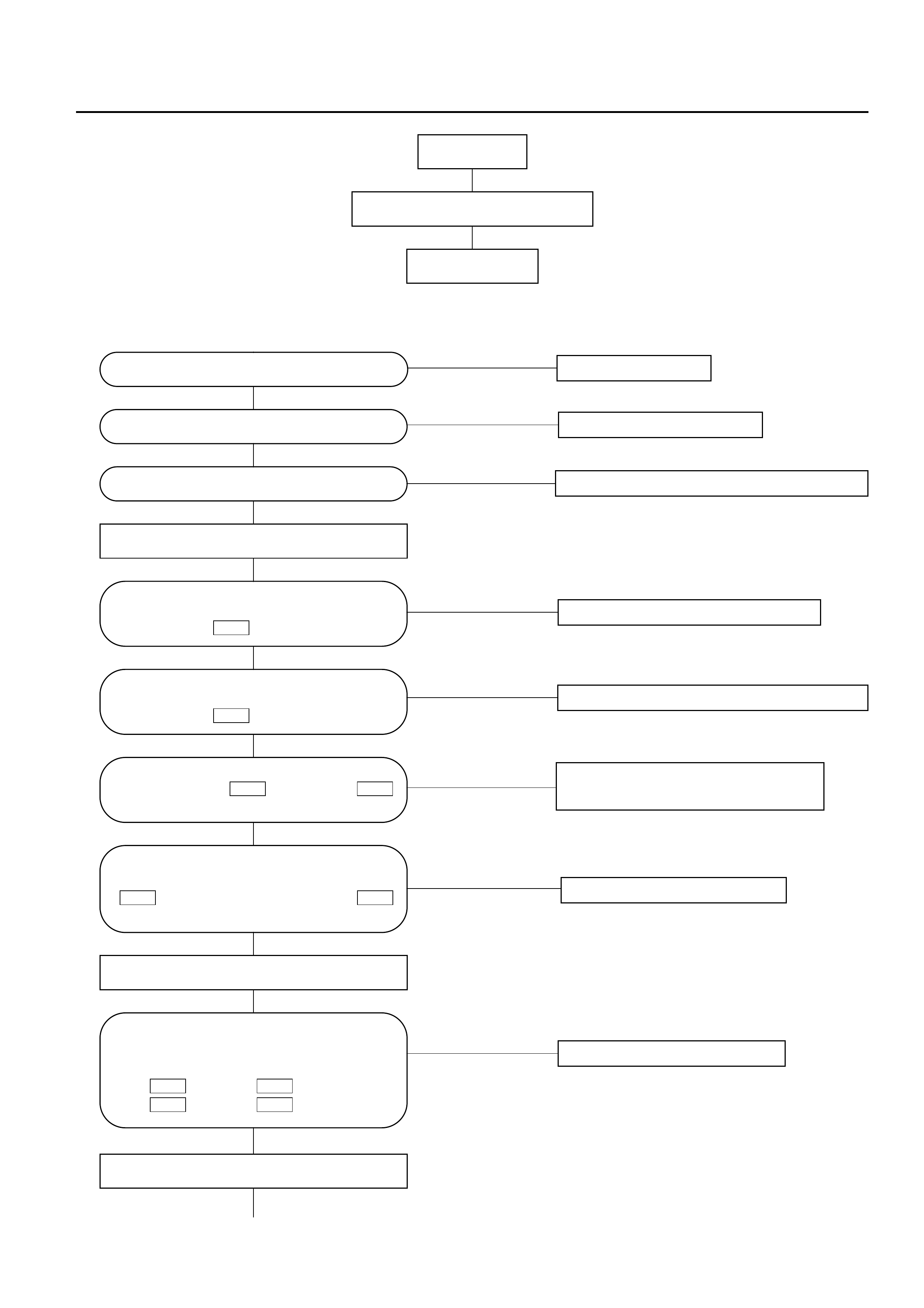
Chart A: Magnet Clutch Does Not work
NO The harness is disconnected.
NO Replace the failed relay.
NO Failure on the power supply system.
NO
NO
NO Replace the fuse.
YES Failure on the magnet clutch.
NO Replace the electronic thermostat.
YES
YES
YES
YES
YES
NO
YES
The harness is disconnected.
Failure on the pressure switch or
refrigerant is insufficient.
Turn the A/C (air conditioner) switch on.
Are the pressure switch side connector
terminals No.1 and No.2
conducted? C-25C-25
Are relays normal?
Is fuse (C-20) 10A normal?
Is the electronic thermostat normal?
Is the battery voltage present between
the chassis harness side connector
terminal No.1 and the ground?
E-3
Is the battery voltage present between
the chassis harness side connector
terminal No.1 and the ground.
C-25
Is the battery voltage present between
the chassis side relay terminal No.3
and the ground, and No.1
and the ground? X-7X-5
YES
Turn the ignition switch off.
Is conduction provided between the
following chassis harness side connecter
terminals?
No.2 and No.2 .
No.4 and No.1 .
E-3X-7 X-7X-5
Turn the ignition switch on (the engine is
started).
Magnet clutch does not work
Chart A
Type of trouble
NO
NO The harness is disconnected.
YES
YES
Failure on PCM (see Chapter 6E for A/C
control with PCM).
Is the battery voltage present between the
chassis harness side connector terminal
No.14 and the ground?
I-32
Is conduction provided between the
following chassis harness side connector
terminals?
No.B14 and No.3 .
No.E15 and No.4 .
X-5C-3 X-7C-1
Disconnect the connector on the
automatic heater/air conditioner control
unit.
I-32
The harness is disconnected between No.1
and No.14 .
I-32X-5
YES
When you turned on the "Auto" switch,
does the battery voltage appear
between the chassis harness connector
terminal No.14 and the ground?
I-32
Failure on the automatic heater/air conditioner
control unit.
NO
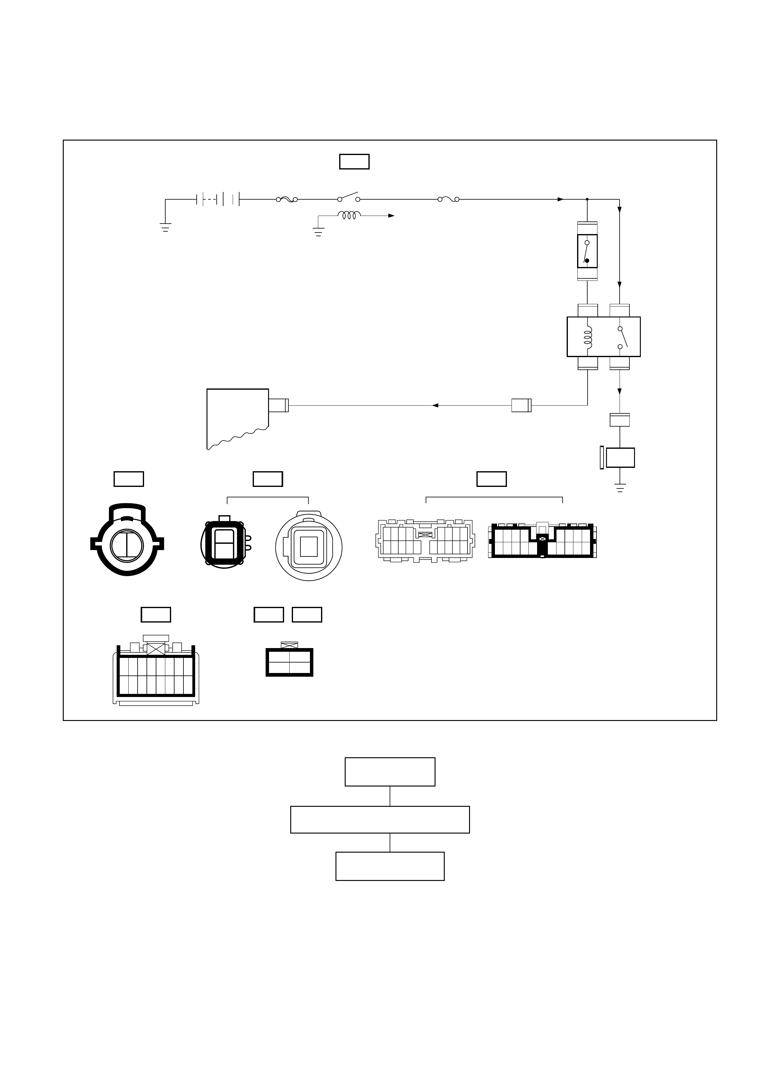
4JX1 Engine
Magnet clutch does not work.
Chart A
Type of trouble
C-25
0.5 BR
C-25
X-5X-5
X-5X-5
21
43
0.5 P/G
FL-1 MAIN
80A C-20
10A A/C
0.5 G/W
0.5 G/O
C-25 E-27 H-16
Pressure
switch
Relay:
Air conditioning
thermostat
Automatic heater/air conditioner
control unit
Relay:
Air conditioning 0.5 BR
1
2
I-32 14
Fan ON
12
I-32 X-5
12
34
E-27
1
Magnet
clutch
B-36
B-36
H-16 16
1
11718161514
7865
121311109
4132
5678
15161718 14
2341
10111213 9
12345678
9 10111213141516
D08RY00183
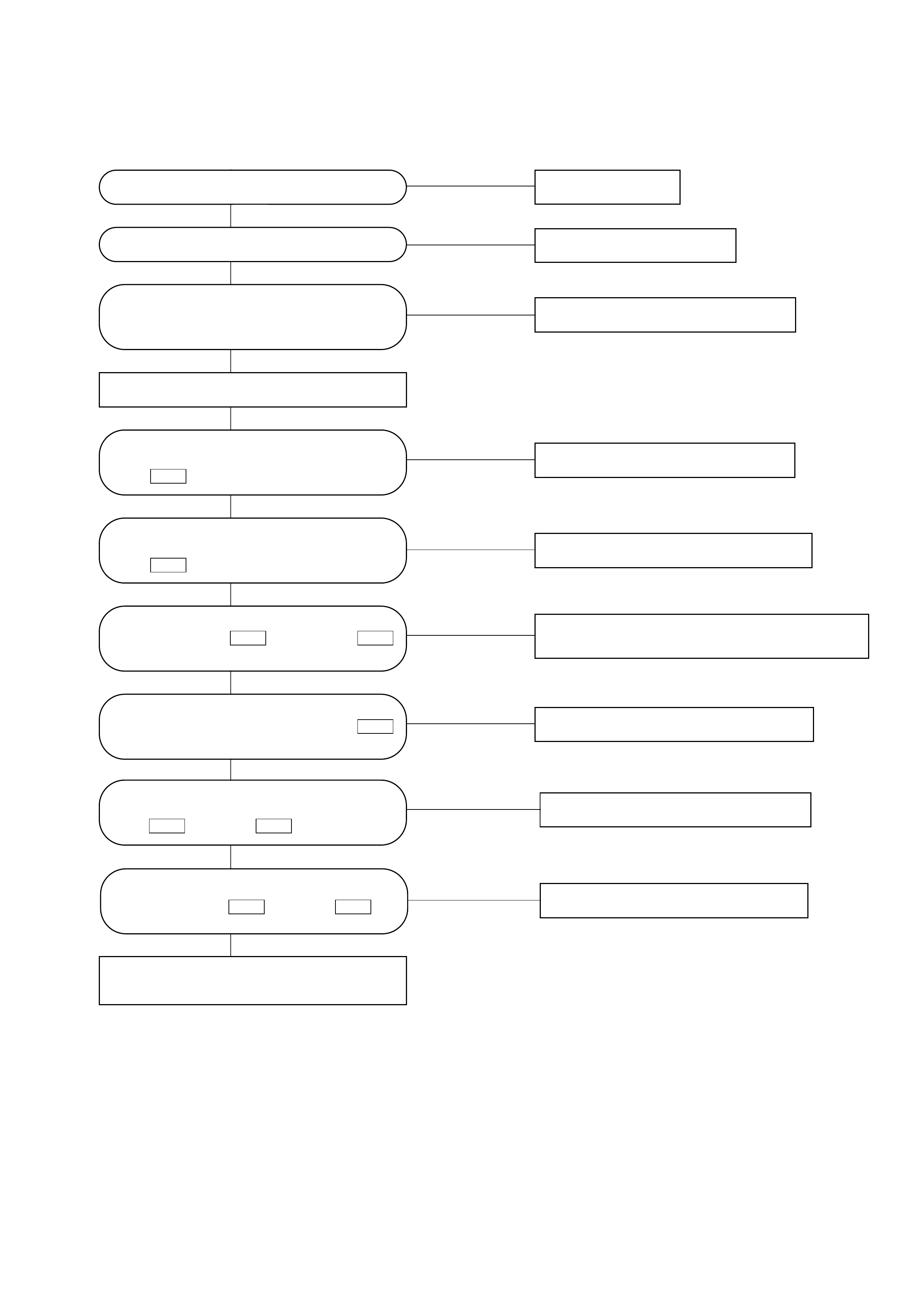
Chart A: Magnet Clutch Does Not Work
NO Replace the fuse.
NO Replace the failed relay.
NO Replace the electronic thermostat.
YES Failure on the magnet clutch.
NO The harness is disconnected.
NO Failure on the power supply system.
YES
Is fuse C-20 (10A) normal?
Are relays normal?
YES
YES
Is the electronic thermostat normal?
YES
Turn the A/C (air conditioner) switch on.
Is the battery voltage present between the
chassis harness side connector terminal
No.1 and the ground?
E-27
NO
Is the battery voltage present between the
chassis harness side connector terminal
No.1 and the ground.
C-25
YES
NO Failure on the pressure switch or refrigerant is
insufficient.
NO The harness is disconnected.
Is the battery voltage present between the
chassis side relay terminal No.1
and the ground? X-5
Are the pressure switch side connector
terminals No.1 and No.2
conducted? C-25C-25
YES
YES
Failure on the automatic heater/air
conditioner control unit.
NO The harness is disconnected.
Is conduction provided between the
chassis harness side connecter terminals
No.1 and No.4 ?
X-5E-27
YES
Are the chassis harness connector
terminals No.14 and No.3 ?
X-5I-32
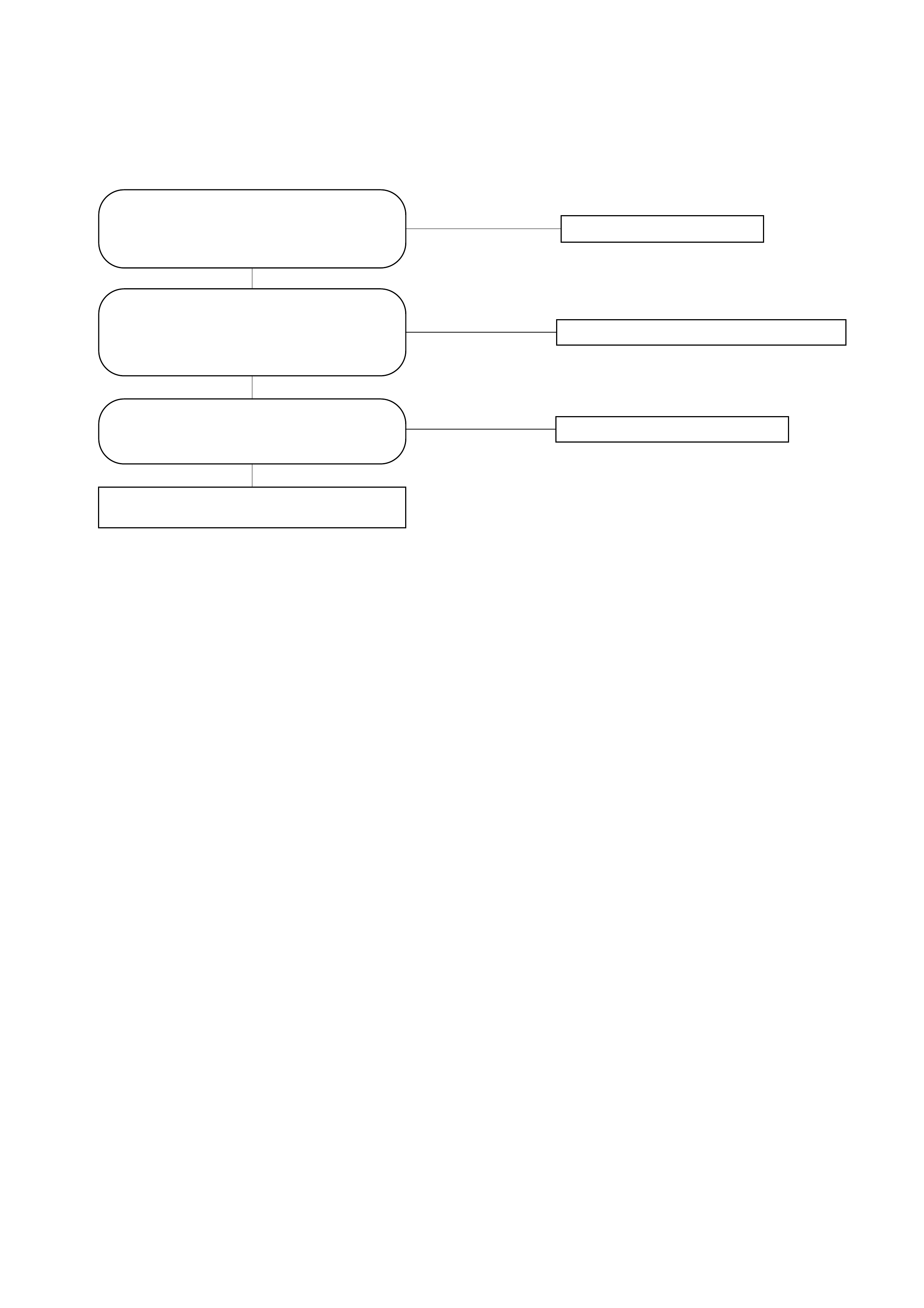
Inspection of the Air Conditioner Room Temperature Setup System
• Conflicts Between the Set Temperature and Actual Room Temperature
NO Replace the failed sensor.
NO
NO
Failure on the automatic heater/air
conditioner control unit.
YES
YES
YES
Is the in car sensor intaking the room
air? (Refer to the later section on "Check
Up".)
Is the air mix link properly attached?
(Make sure that selecting FH or FC using
the lever respectively sets the mix door
to the full hot or full cool.)
Are the interior temperature sensor and
the outside air temperature sensor
functioning normally?
Failure on the in car sensor.
Failure on the air mix link or the actuator.
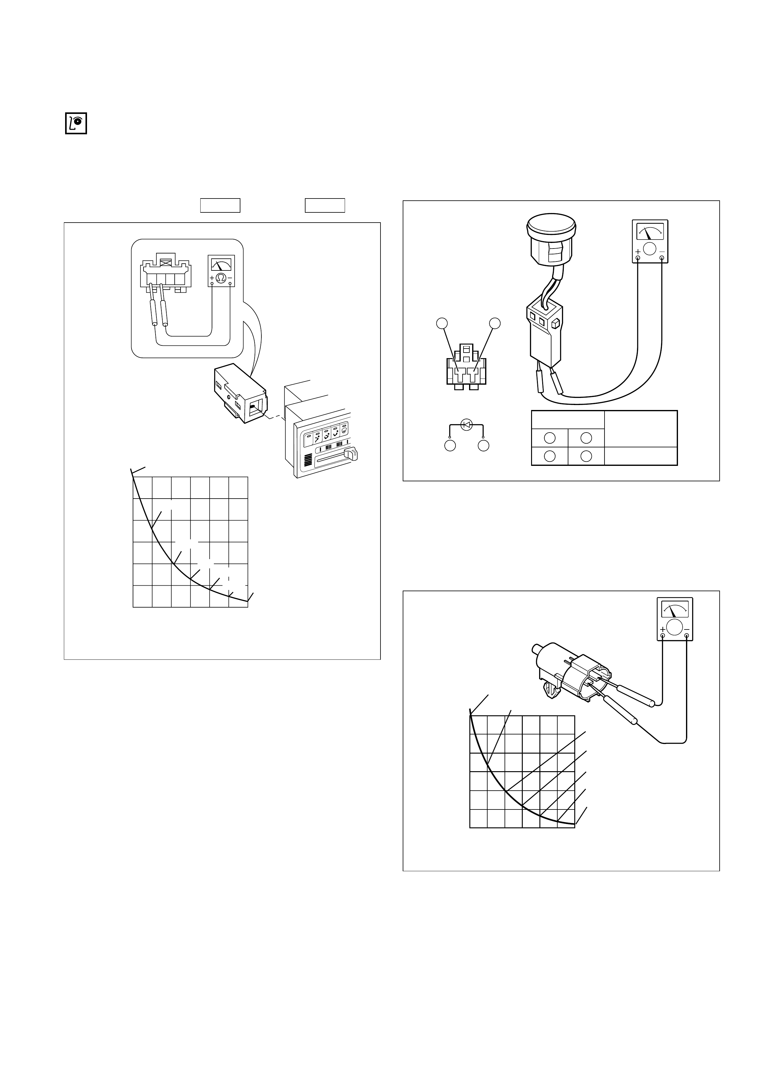
INDIVIDUAL INSPECTION
In Car Sensor
1. Disconnect the in car sensor connector (I-34).
2. Measure resistance between the in car sensor
side terminal No.3 and No.4 .
Sun Sensor
1. Disconnect the sun sensor connector (I-35).
2. Measure the current value on the sun sensor
when placed it approximately 15 cm away from
60W incandescent lamp.
Ambient Sensor
1. Disconnect the connector (C-86) on the ambient
sensor.
2. Measure resistance between the ambient
sensor side terminals.
I-34
I-34
Temperature on the Sensor
Temperature Detector(¡C)
Sensor Resistance
Value(k‰)
4321
-20
0
5
10
15
20
25
30
-10 0 10 20 30 40
17.09
9.93
3.75
2.24
6.0
1.6
30.69
865RX007
‰
0100-10-20 30 4020
5
10
15
20
25
30
Temperature on the Sensor
Temperature Detector(¡C)
Sensor Resistance
Value(k‰)
17.09
30.69
9.93
6.0
3.75
2.24
1.6
C01RX012
—
Testing rod
12
A
Current
value
40 A or more
+
1 2
21
D06RY00001
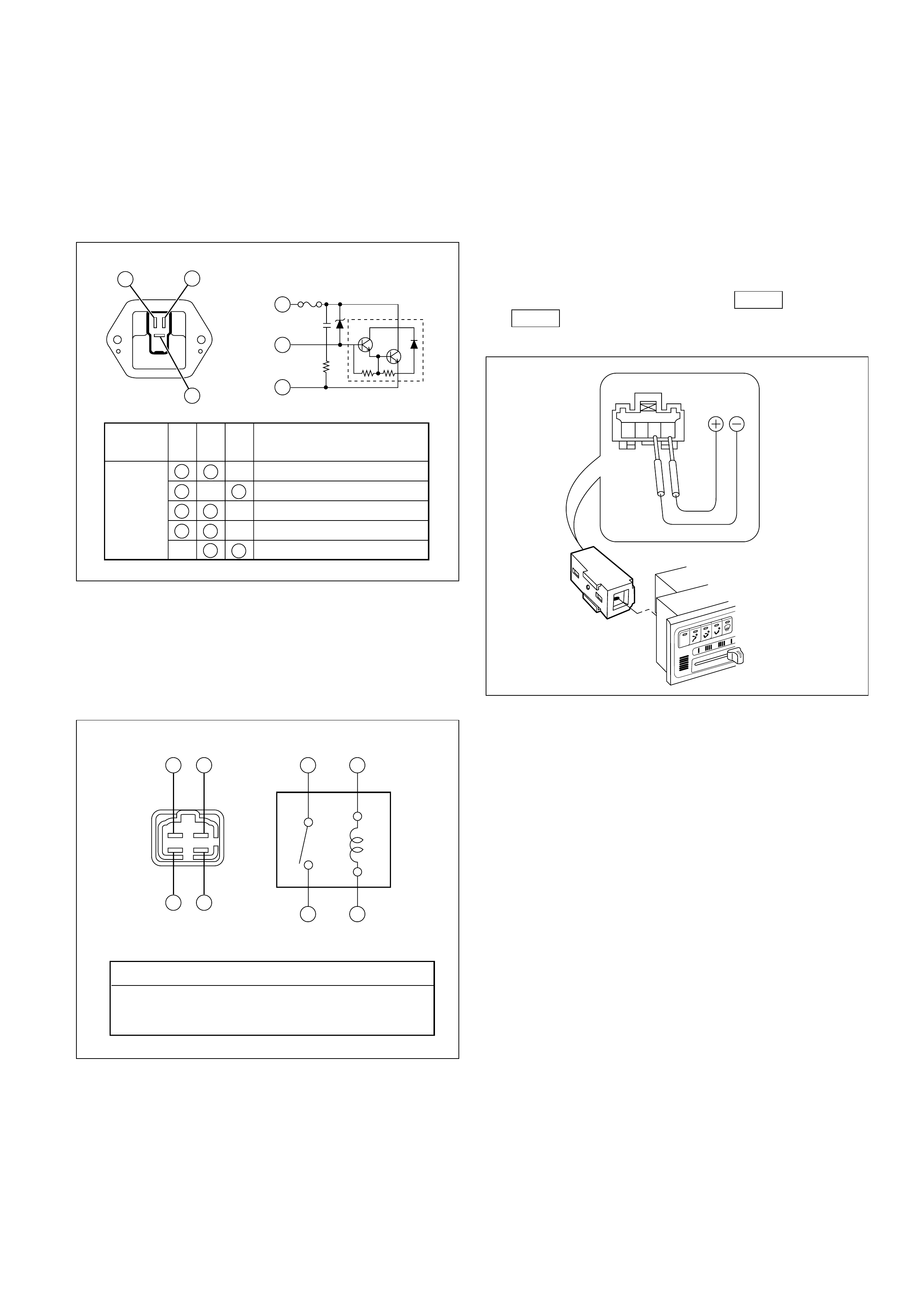
Power Transistor
1. Remove the power transistor connector (I-47)
from the evaporator assembly.
2. Check the conduction between the power
transistor side terminals.
MAX HI Relay
1. Remove the MAX HI relay connector (B-64) from
the blower assembly.
2. Check the conduction between the MAX HI relay
side terminals.
In Car Sensor
1. Turn on the ignition switch (the engine is
started). Start the air conditioner in "Full Auto".
2. Make sure that the in car sensor suctions
cigarette smokes and such.
3. Dismount the in car sensor from the automatic
heater/air conditioner control unit. Connect (+)
end and (-) end of the battery to the aspirator
motor side terminals No.1 and No.2
, respectively, then
check if the motor runs normally.
I-34 I-34
4321
C01RW020
43 34
1
2
21
No continuity between terminals (2) and (4).
Continuity between terminal (2) and (4) when battery
voltage is applied between (1) and (3).
C01RY00003
1
2
3
Terminal
No. Conduction
Conducted (50‰ maximum)
Conducted (100‰ maximum)
Conducted (220‰ maximum)
Not conducted
Not conducted
123
Testing
rod
1
23
C01RY00002
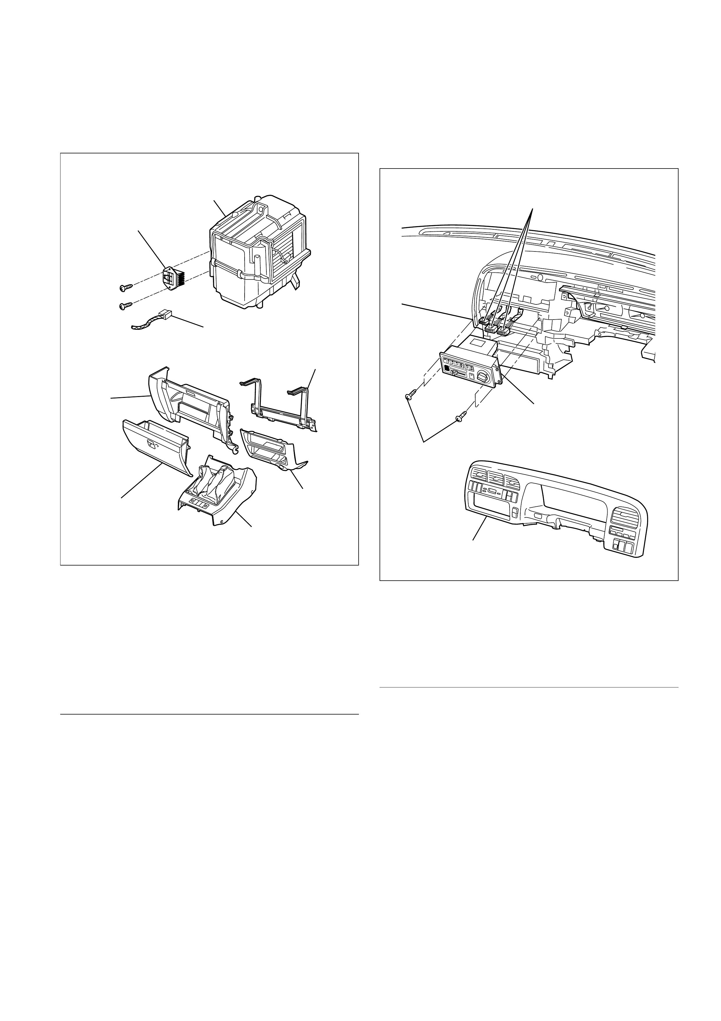
ON-VEHICLE SERVICE
Power Transistor
Legend
(1) Evaporator Assembly
(2) Passenger Knee Bolster Reinforcement(3) Lower Cluster(4) Front Console(5) Glove Box
(6) Instrument Panel Passenger Lower Cover(7) Power Transistor Connector(8) Power Transistor
Removal1. Remove front console.
2. Remove lower cluster.
3. Remove glove box.
4. Remove instrument panel passenger lowercover.5. Remove passenger knee bolster reinforcement.6. Disconnect the power transistor connector.
7. Remove power transistor.
InstallationTo install, follow the removal step in the reverse
order.
Automatic Heater/Air Conditioner ControlUnit
Legend
(1) Connector
(2) Automatic Heater / Air Conditioner Control
Unit
(3) Instrument Panel Cluster
(4) Set Screw
Removal
1. Disconnect the battery ground cable.
2. Remove instrument panel cluster.
• Refer to Instrument Panel Assembly in Body
Structure section.
3. Disconnect the automatic heater / air conditioner
control unit connector.
4. Remove automatic heater/ air conditioner
control unit.
Installation
To install, follow the removal step in the reverse
order.
7
6
5
4
3
2
8
1
874RY00001
3
2
4
1
865RY00007
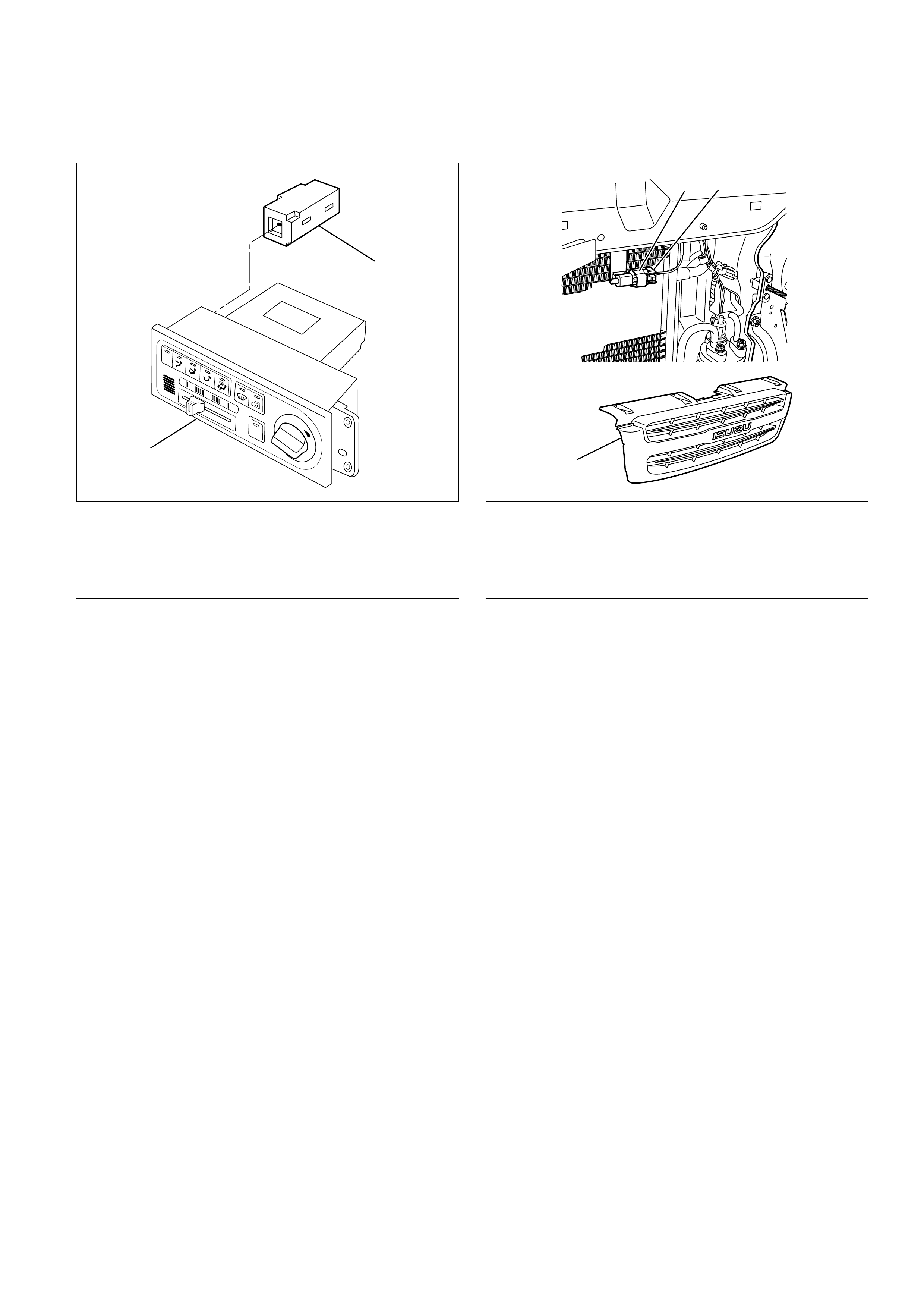
In Car Sensor
Legend
(1) In Car Sensor(2) Automatic Heater / Air Conditioner Control
Unit
Removal1. Disconnect the battery ground cable.2. Remove the automatic heater / air conditionercontrol unit.
•Refer to the automatic heater / air conditionercontrol unit section.
3. Remove in car sensor.
Installation
To install, follow the removal step in the reverse
order.
Ambient Sensor
Legend
(1) Ambient Sensor
(2) Sensor Connector
(3) Radiator Grill
Removal
1. Disconnect the battery ground cable.
2. Remove radiator grille.
• Refer to Radiator Grille in Body Structure
section.
3. Disconnect the ambient sensor connector.
4. Remove the ambient sensor.
Installation
To install, follow the removal step in the reverse
order.
2
1
865RY00006
12
3
875RY00001
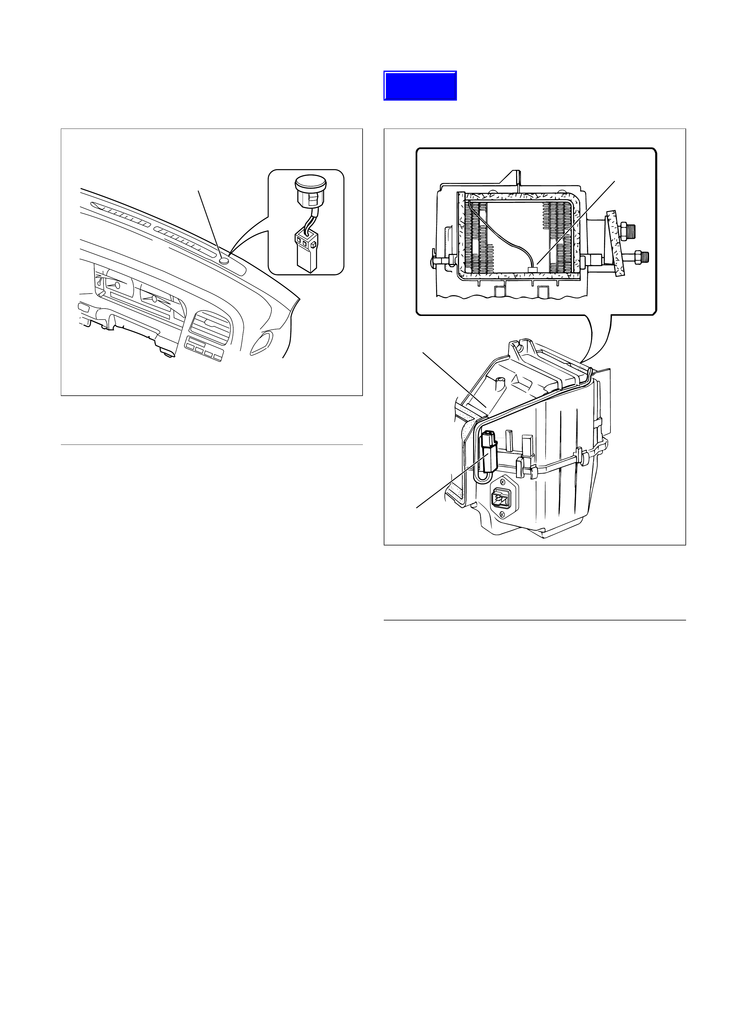
Sun Sensor
Legend
(1) Sun Sensor
Removal
1. Disconnect the battery ground cable.
2. Remove the sun sensor.
3. Disconnect the sun sensor connector.
Installation
To install, follow the removal step in the reverse
order.
Electronic Thermostat
Legend
(1) Duct Sensor
(2) Thermostat Assembly
(3) Evaporator Assembly
Removal
1. Disconnect the battery ground cable.
2. Remove evaporator assembly.
• Refer to Evaporator Assembly section.
3. Remove electronic thermostat.
Installation
To install, follow the removal step in the reverse
order.
1
826RY00001
1
3
2
874RY00002
Techline
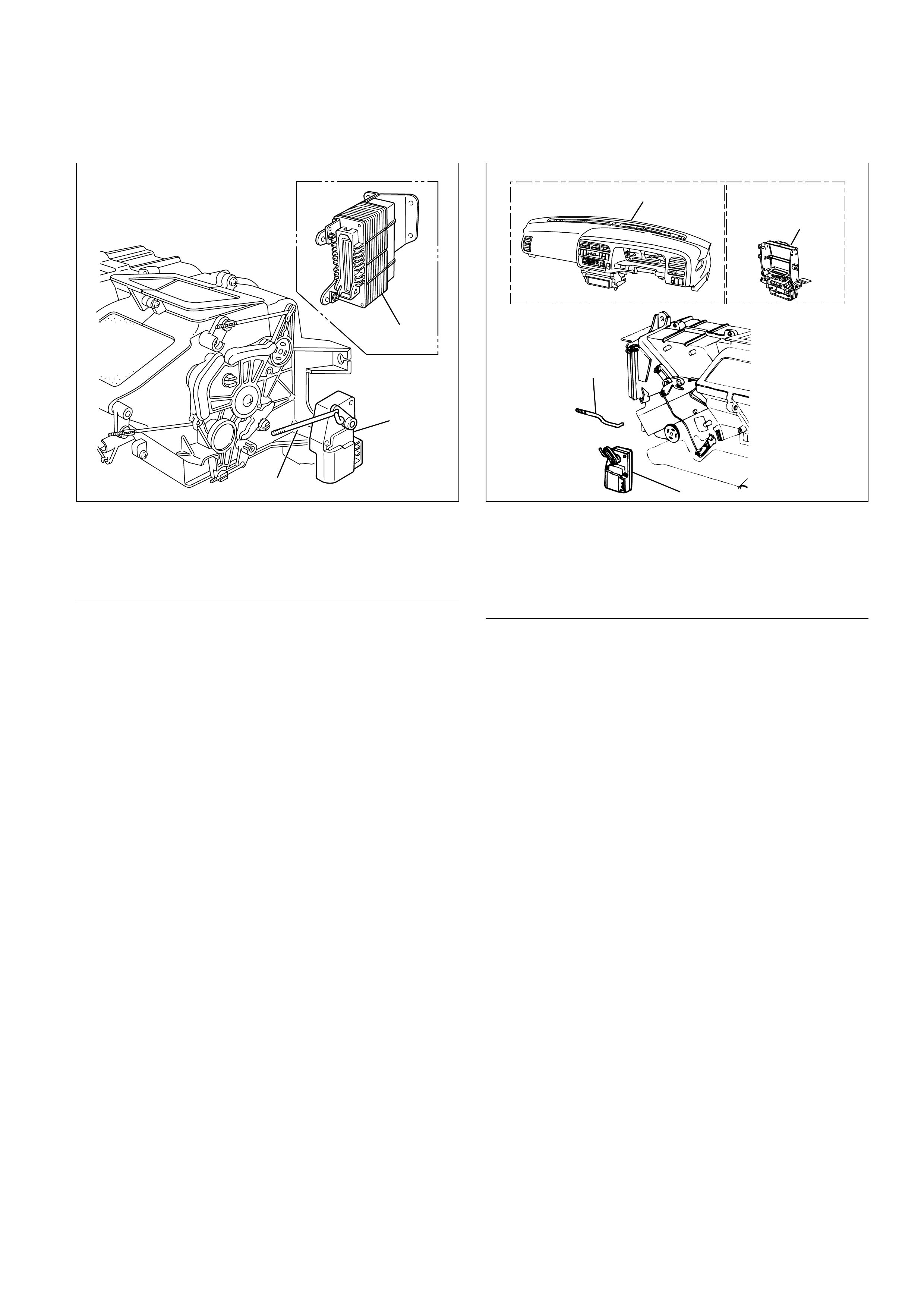
Mode Actuator
Legend
(1) A/T Control Unit
(2) Mode Actuator
(3) Actuator Rod
Removal
1. Disconnect the battery ground cable.
2. Remove the A/T control unit.
•The connector shall remain connected.
3. Remove the actuator rod.
4. Remove the mode actuator.
Installation
To install, follow the removal step in the reverse
order.
MIX Actuator
Legend
(1) Instrument Panel Assembly
(2) Instrument Panel Center Bracket
(3) Actuator Rod
(4) Mix Actuator
Removal
1. Disconnect the battery ground cable.
2. Remove the instrument panel assembly.
• Refer to the Instrument Panel Assembly in
Body Structure section.
3. Remove the instrument panel center bracket.
4. Remove the actuator rod.
5. Remove the mix actuator.
Installation
To install, follow the removal step in the reverse
order.
2
1
3
860RW030
2
3
4
1
20 25 30
AUTO
A/C
OFF
AUTO
LO
HI
860RY00004
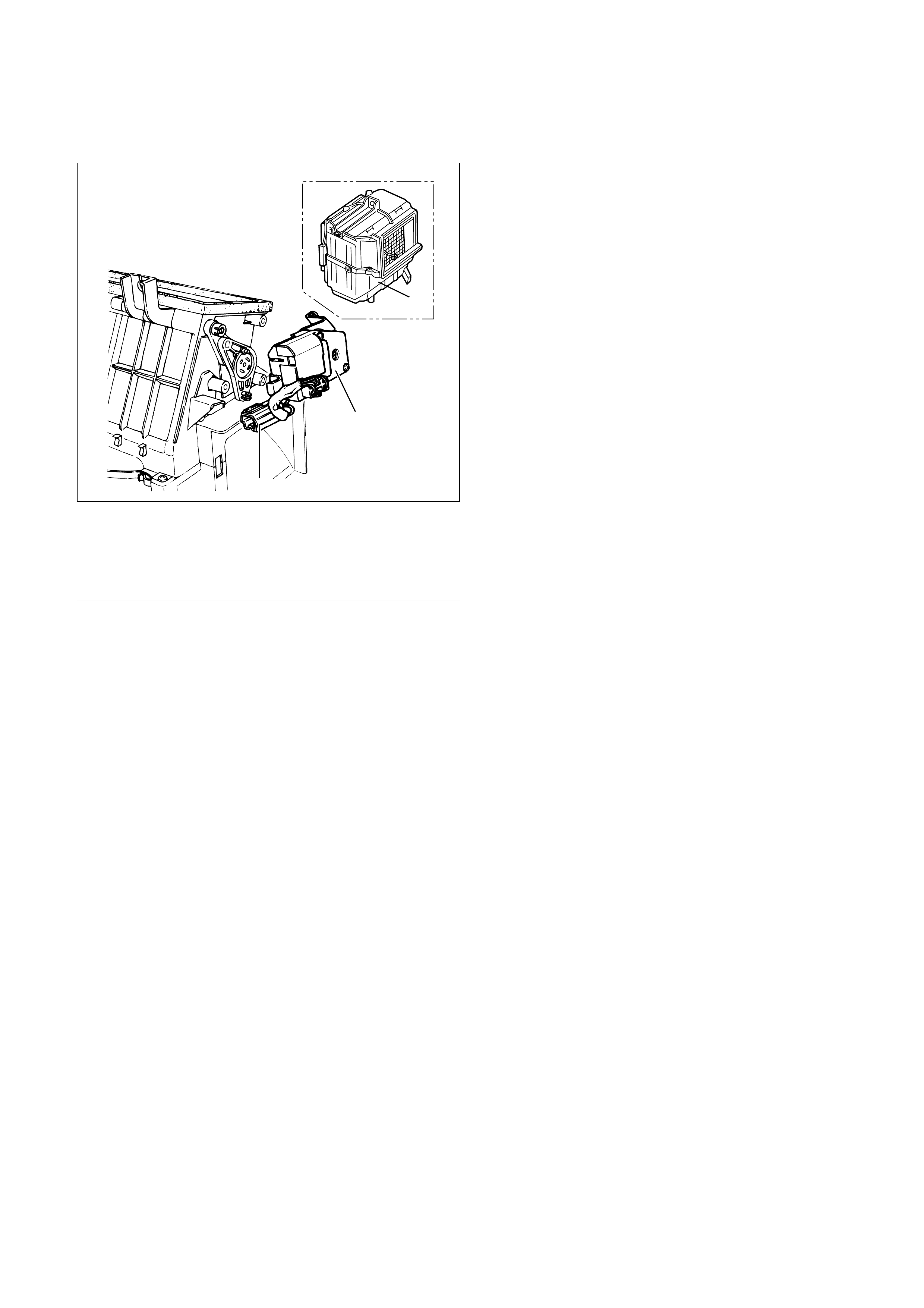
Intake Actuator
Legend
(1) Evaporator Assembly
(2) Intake Actuator
(3) Intake Actuator Connector
Removal
1. Disconnect the battery ground cable.
2. Discharge and recover refrigerant.
• Refer to Refrigerant Recovery in this section.
3. Remove the evaporator assembly.
• Refer to Evaporator Assembly section.
4. Disconnect the intake actuator connector.
5. Remove the intake actuator.
Installation
To install, follow the removal step in the reverse
order.
1
2
3
860RX018