DENSO INTERNA TIONAL AUSTRALIA PTY LTD
MAC-A552/MAC-A553
HOLDEN
JACKAROO
PART NUMBER 9211 3741 (TURBO DIESEL)
9211 3740 (V6 PETROL)

© 2001 DENSO INTERNA TIONAL AUSTRALIA PTY L TD
All Rights Reserved. This book may not be reproduced or copied,
in whole or in part, without the written permission of the publisher.
IMPORTANT NOTICE
INTRODUCTION
This manual has been designed for technicians who are qualified and educated in the proper procedures of vehicle
safety, handling and maintenance; experienced in installation of car air conditioning or who are able to carry out
installation procedures when given instructions by an experienced technician in a supervisory capacity; and are
certified to handling refrigerant.
1. Take special care to ensure that clearance between air conditioning components and other components such as
brake parts, fuel system and electric wires as specified in this manual.
2. If a problem is found with the air conditioning system due to installation, refer back to the manual to correct the
problem(s).
3. Vehicle and air conditioning kit components as well as installation procedures are subject to change without prior
notice. Refer to the latest installation manual and service information. Any changes affecting the above items will
be given in the form of a “Installation instructions for air conditioning (Supplement)” (issued by DENSO) or a
service bulletin (issued by the manufacturer).
DEFINITION OF TERMS
! W ARNING : Describes precautions that should be observed in order to prevent injury or death to the user during
installation.
! CAUTION : Describes precautions that should be observed in order to prevent damage to the vehicle or its
components, which may occur during installation if insufficient care is taken.
NOTE : Provides additional information that facilitates installation work.
FRONT, REAR : Shows the direction when viewed from the driver’s seat.
LEFT, RIGHT
DENSO INTERNATIONAL AUSTRALIA PTY LTD
A.C.N. 081 951 402
255 Melrose Drive
TULLAMARINE VIC 3043
First Issue: September , 2001
Publication No: MAC-A552/MAC-A553
Printed in Australia

FOREWORD
This manual has been published to explain how to install the air conditioning for HOLDEN JACKAROO UBS. When
installing the air conditioning, installation should be performed as described in this manual.
[VEHICLE APPLICATION]
VEHICLE NAME MODEL CODE PRODUCTION PERIOD STEERING POSITION DESTINATION
JACKAROO UBS 2001 PETROL 3.5L AUSTRALIA
DIESEL 3.0L
1. GENERAL INFORMATION
1-1 PRECAUTIONS DURING INSTALLATION
1-2 INSTALLATION PREPARATION
1-3 TIGHTENING TORQUE
1-4 PRECAUTIONS FOR SAFETY INSTALLATION
1-5 PIPE JOINT PRECAUTIONS
1-6 GENERAL PRECAUTIONS IN ASSEMBLY
1-7 CHARGING REFRIGERANT (HFC-134a)
2. INSTALLATION INSIDE PASSENGER COMPARTMENT
3. INSTALLATION INSIDE ENGINE COMPARTMENT
4. AFTER INSTALLATION
4-1 CHARGING REFRIGERANT (HFC-134a)
4-2 FINAL LEAKAGE CHECK
4-3 RE-ADJUSTMENT OF COMPRESSOR BELT
4-4 FINAL INSPECTION (SAFETY CHECK)
4-5 RESTORE THE VEHICLE
4-6 FINAL INSPECTION (SAFETY CHECK)
MAC-A552/MAC-A553
DENSO INTERNA TIONAL AUSTRALIA PTY L TD
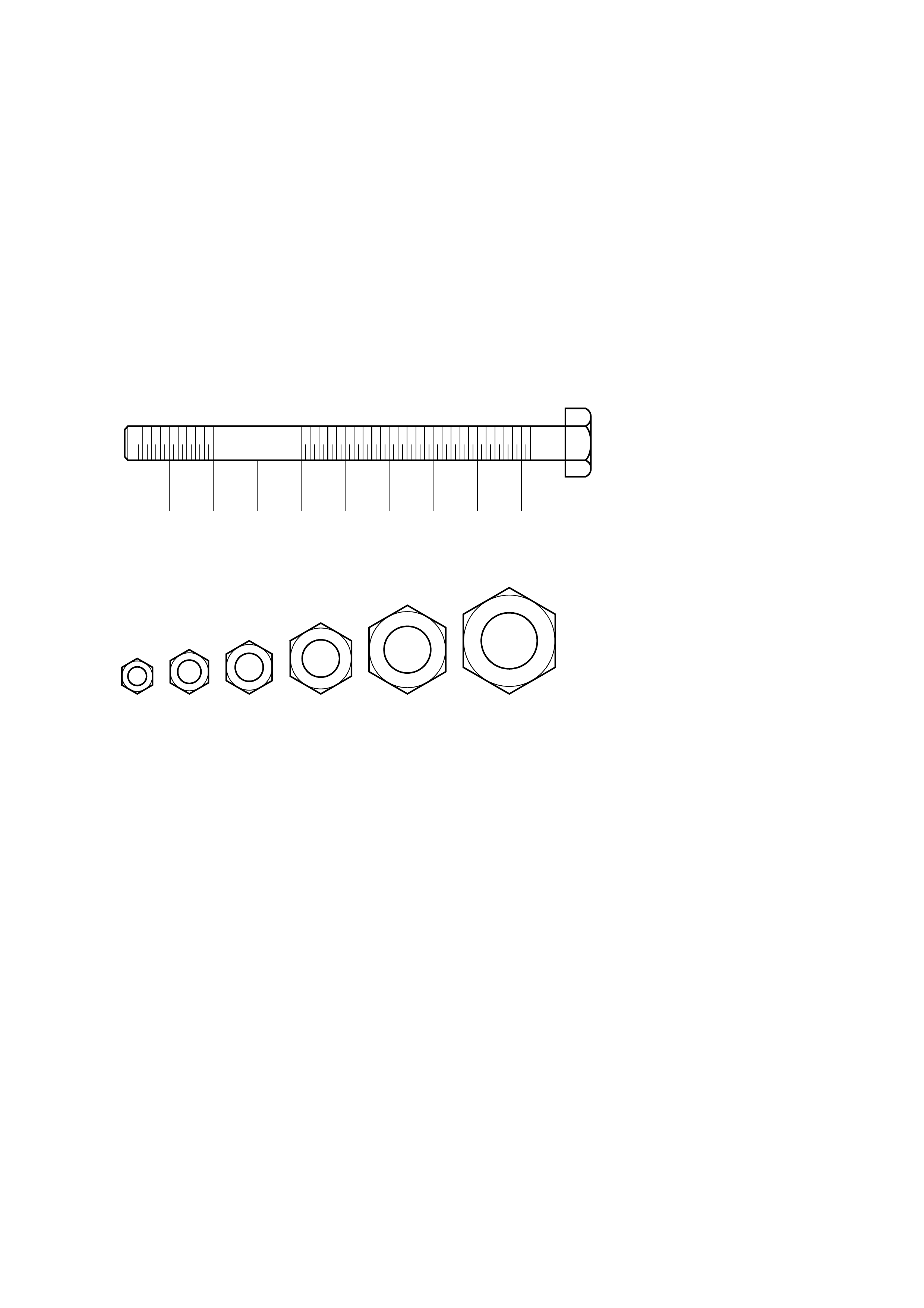
BOLT LENGTH RULER (mm)
BOLT DIAM. & HEX. HEAD (mm)
(mm)
20 1030405060708090
M14M12M10M8M6M5
– 1 –
1. GENERAL INFORMATION
1-1 PRECAUTIONS DURING INSTALLATION
1. The contents given in “WARNING” and “CAUTION “ in this manual must be adhered to during installation. If they
are ignored, not only the functions of the air conditioning are hindered, but also personal injury or damage to the
vehicle may result. Always carry out the installation in accordance with the “WARNING” and “CAUTION” as noted.
2. Safety Precautions
(a) If installation is carried out by more than two persons, always pay attention to co-worker’s safety.
(b) When the engine is running, make sure that sufficient ventilation is provided.
(c) Take special care when working with heated, rotating, sliding, or moving parts, to prevent bodily injury.
(d) When raising the vehicle, refer to the appropriate manufacturer’s service manual.
(e) For heavy duty trucks, when tilting the cabin forward, refer to the service manual provided by the vehicle’s
manufacturer to prevent damage or personal injury. Make sure the cabin is locked down after it has been tilted
forward to prevent it from closing.
1-2 INSTALLATION PREPARATION
(1) Prior to installing the air conditioning, check the following for damage or malfunctions.
(a) Internal and external trim and bodywork.
(b) Engine idle speed.
(c) Engine cooling system.
(d) All vehicle functions. (Headlights, indicators, horn, etc.)
(2) Air Conditioning parts preparation
(a) Make sure that the correct kit has been selected for the installation.
(b) When unpacking the kit, lay out all parts in order of installation and check for missing or damaged parts.
(c) When installing the air conditioning, use fender covers, floor covers and seat covers for protection.
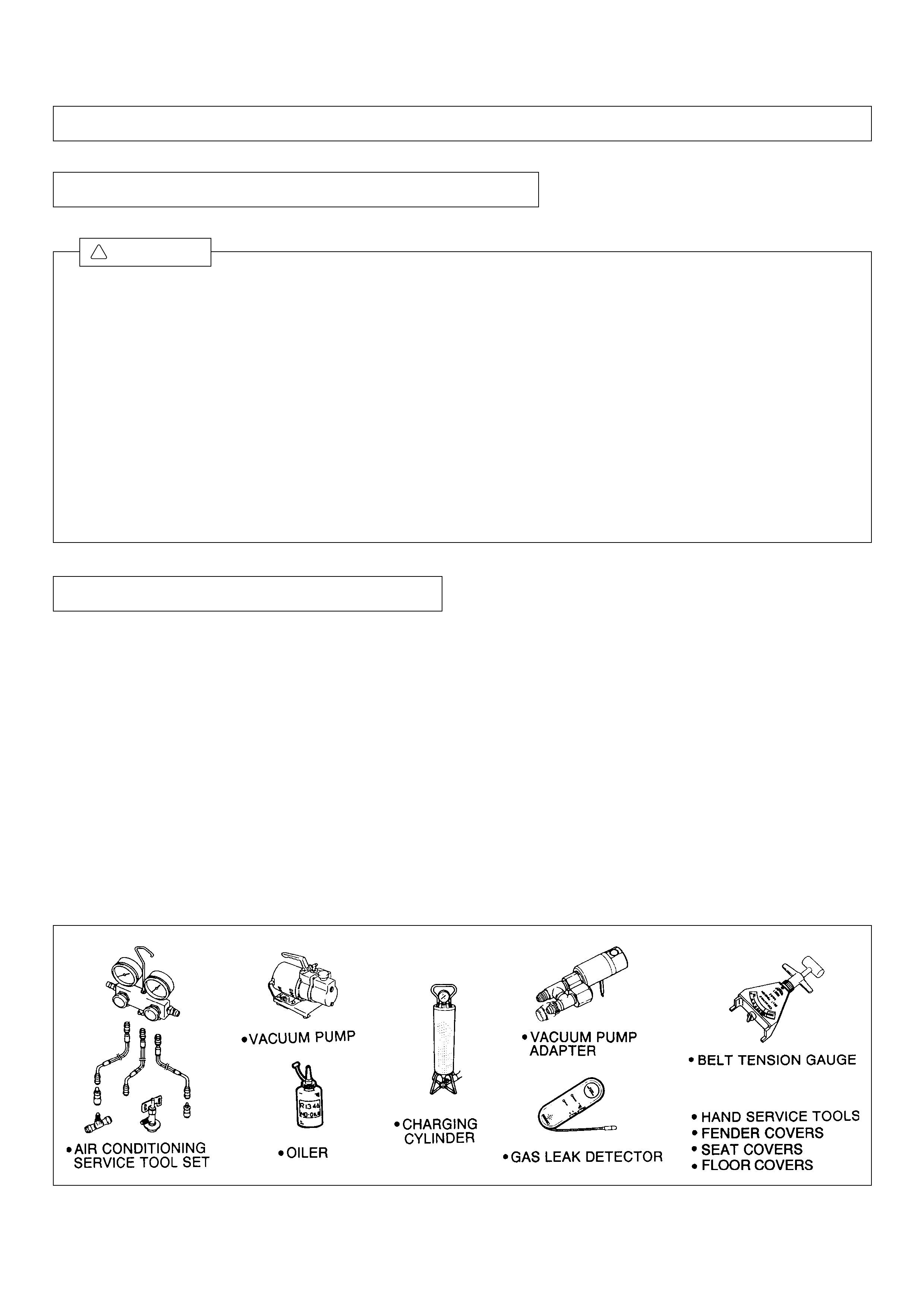
[INSTALLATION TOOLS]
WARNING
!
– 2 –
[Unit : kgf·cm]
1-3 TIGHTENING TORQUE
(1) Where tightening torque is specified, always tighten there with the specified torque.
(2) Where tightening torque is not specified, refer to the tightening torque table.
(3) Bolts marked with i must be used for engine components, which are likely to be subject to heavy load. Never
substitute the bolts marked i with other bolts.
(4) Nuts must be fastened with the tightening torque specified for the related bolts.
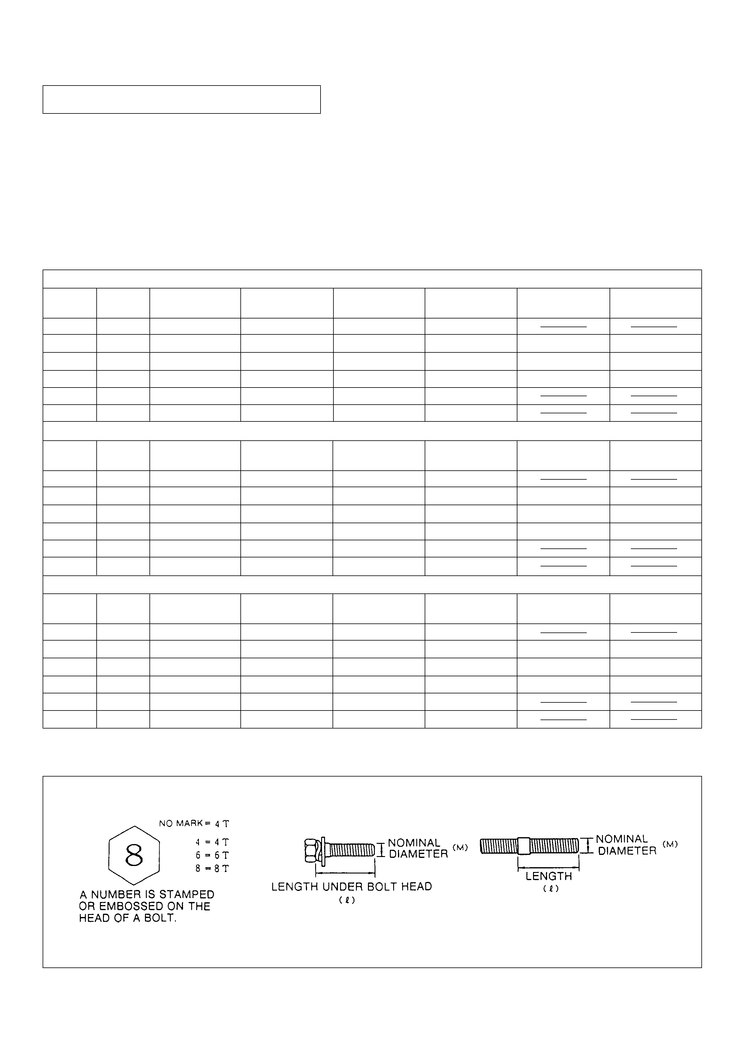
[TIGHTENING TORQUE TABLE (GENERAL)]
6 1.00 4.0± 0.7 4.7± 0.7 5.8± 1.0 7.9± 1.3
8 1.25 9.4± 1.8 11.5± 2.1 14.1± 2.4 18.7± 3.6 21.7± 4.3 28.1± 5.4
10 1.25 18.8± 3.6 23.8± 4.6 29.0± 5.7 38.2± 7.4 44.8± 8.6 56.7±11.4
12 1.25 37.4± 6.8 43.2± 8.5 52.8±10.4 69.9±13.6 79.6±15.7 104.5±20.7
14 1.50 54.7±10.8 67.0±13.2 79.3±15.8 108.1±21.6
16 1.50 82.9±16.5 100.9±20.2 126.0±25.2 165.7±33.1
6 1.00 55± 10 65± 10 80± 15 110± 20
8 1.25 130± 25 160± 30 195± 35 260± 50 300± 60 390± 75
10 1.25 260± 50 330± 65 400± 80 530± 105 620± 120 800±160
12 1.25 480± 95 600± 120 730± 145 970± 190 1100± 220 1450± 290
14 1.50 760± 150 930± 185 1100± 220 1500± 300
16 1.50 1150± 230 1400± 280 1750± 350 2300± 460
6 1.00 5.4± 1.0 6.4± 1.1 7.8± 1.4 10.8± 1.9
8 1.25 12.7± 2.5 15.7± 2.9 19.1± 3.4 25.5± 5.9 29.4± 5.9 38.2± 7.4
10 1.25 25.5± 4.9 32.4± 6.3 39.2± 7.8 52.0±10.2 60.8±11.8 78.5±15.6
12 1.25 47.1± 9.3 58.8±11.7 71.6±14.2 95.1±18.6 107.9±21.5 142.2±28.3
14 1.50 74.5±14.7 91.2±18.1 107.9±21.6 147.1±29.4
16 1.50 112.8±22.5 137.3±27.5 171.6±34.3 225.6±45.1
Diam.
(mm) Pitch
(mm)
[Unit : N·m]
4T 5T 6T 7T 8T 10T
Diam.
(mm) Pitch
(mm) 4T 5T 6T 7T 8T 10T
Diam.
(mm) Pitch
(mm)
[Unit : ft·lbf]
4T 5T 6T 7T 8T 10T
[IDENTIFICATION OF BOLT STRENGTH (BOLT SIZES)]
– 3 –
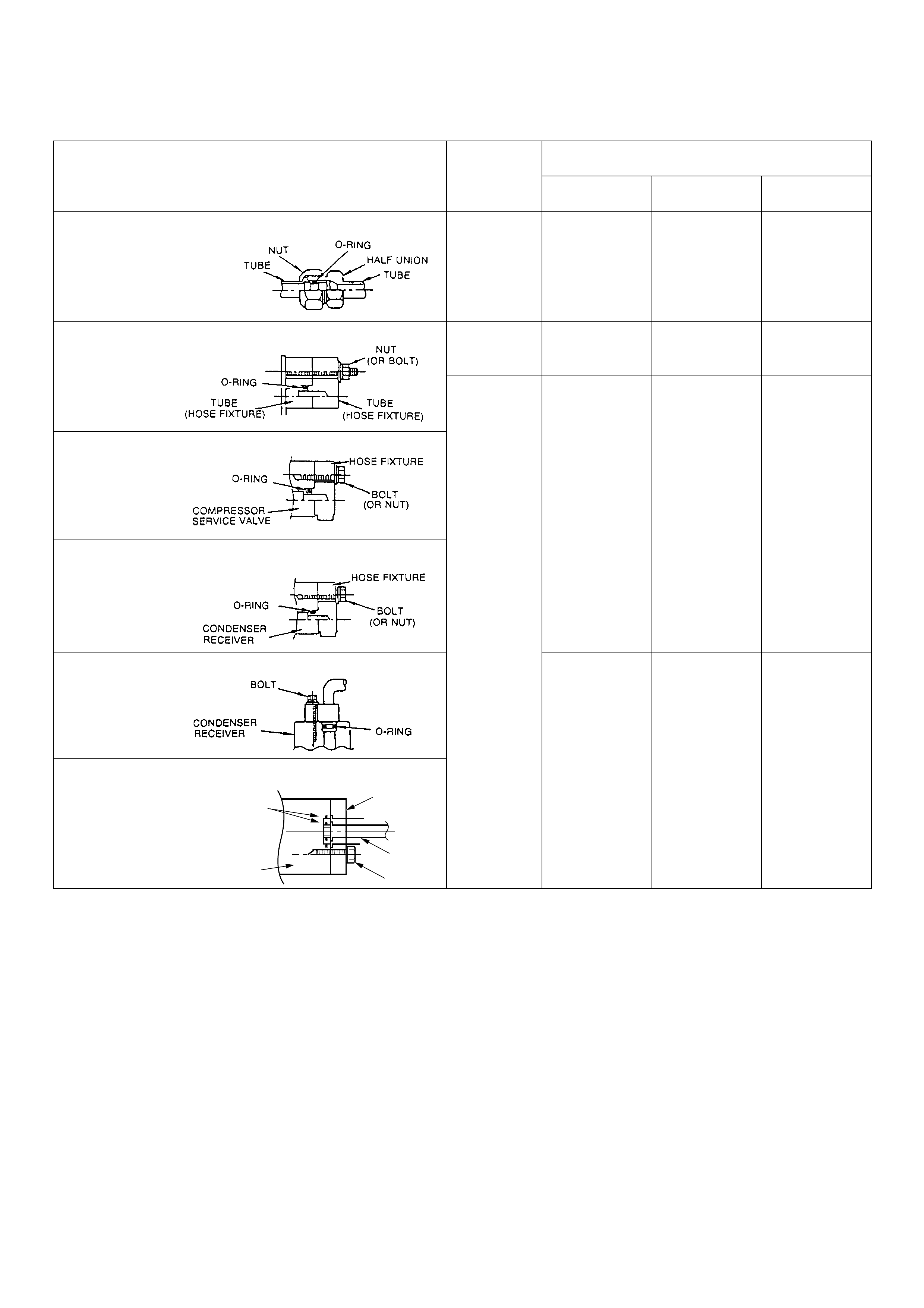
[TIGHTENING TORQUE TABLE (FOR PIPES)]
STRUCTURE
<GENERAL PIPING (UNION TYPE)>
<GENERAL PIPING (BOLT, NUT TYPE)>
<COMPRESSOR>
<CONDENSER (EXCEPT MF TYPE) >
<COOLING UNIT>(EXCEPT ONE BOLT PLATE TYPE)
TIGHTENING TORQUE
N·m
N·m
BOLT & NUT
SIZE
1/4"
φ
8
1/2"
5/8" OR 6/8"
TUBE SIZE
7.8±1.0 80±10 5.8±0.7
13.7±1.0 140±10 9.8±1.0
22.5±2.0 230±20 16.2±1.7
32.3±2.0 330±20 23.4±1.7
9.8±2.0 100±20 7.2±1.3
kgf·cm ft·lbf
kgf·cm ft·lbf
M6
5.4±1.0 55±10 4.0±0.7
<CONDENSER (MF TYPE)>
<RECEIVER>
<COOLING UNIT >
(ONE BOLT PLATE TYPE)
O-RING
BOLT
TUBE
COOLING
UNIT
PUSH
PLATE
– 4 –
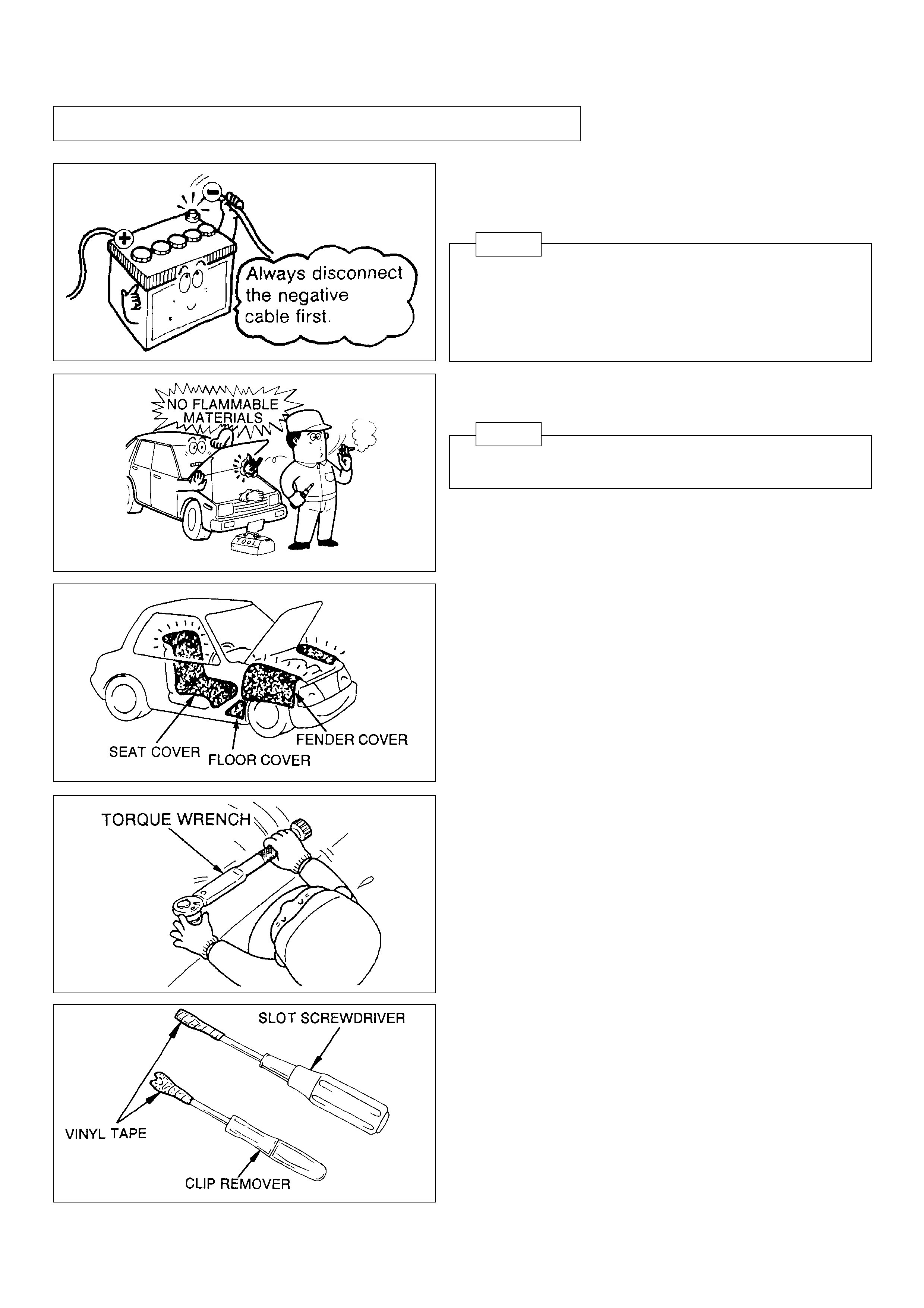
(5) Take care not to scratch any part of the vehicle.
Bind the tips of tools (clip remover, slot screwdriver etc.)
with a piece of vinyl tape to prevent damage to parts of the
vehicle.
1-4 PRECAUTIONS FOR SAFETY INSTALLATION
(1) Do not proceed with the installation until the battery cables
have been disconnected or a short-circuit may result.
NOTE
1. Always disconnect the NEGATIVE CABLES first.
2. When RECONNECTING the cables, make sure to
connect the positive cable to the positive battery terminal
and the negative cable to the negative battery terminal.
(4) The bolts,nuts and fittings where specified must be torqued
to proper specification. If torque is not specified, refer to
TIGHTENING TORQUE TABLE on page 3.
(3) Use protective covers to avoid damage to the vehicle and
the air conditioning parts.
• Seat covers
• Fender covers
• Floor covers
(2) Do not smoke or expose open flame near the vehicle during
installation.
NOTE
Pay special attention when working on the fuel system.
– 5 –
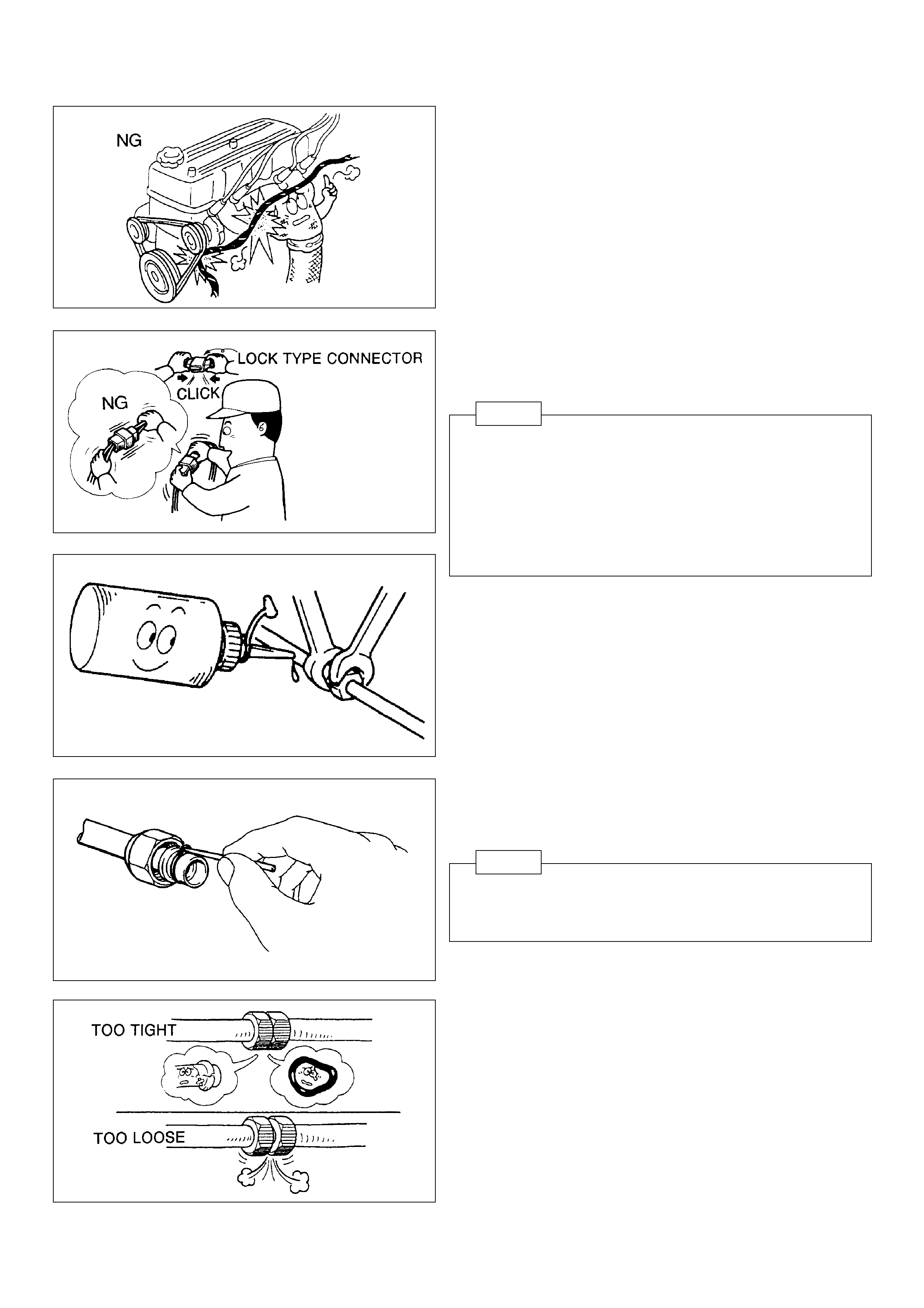
(6) When installing the A/C harnesses, route properly avoiding
interference with surrounding parts.
(7) Do not pull on vehicle wires and/or wire harnesses. To
uncouple electrical connectors, pull only on the connector
itself to avoid damage.
NOTE
In case of lock type connectors, make sure that the
connectors are unlocked before disconnecting.
When re-connecting the connectors, insert them until a
clicking noise is heard. After they are connected, hold
and pull them gently to check that they are connected
properly.
(8) Before making any hose and tube connections, apply a
few drops of compressor oil to the seat of O-ring to avoid
refrigerant leakage.
(9) When removing an O-ring from a tube, use a wooden or
nylon awl to prevent damaging the tube.
NOTE
Always replace the existing O-rings with new ones
specified for refrigerant HFC-134a.
(10)When tightening or loosening fittings, use two wrenches
to prevent the tubes from twisting. After loosening the
fittings, tighten them with specified torque.
– 6 –
(11) Do not remove protective caps from fittings until each
component is ready for connection.
NOTE
If the receiver is left uncapped for a long time, the desiccant
inside the receiver may absorb moisture, causing damage
to the air conditioning.
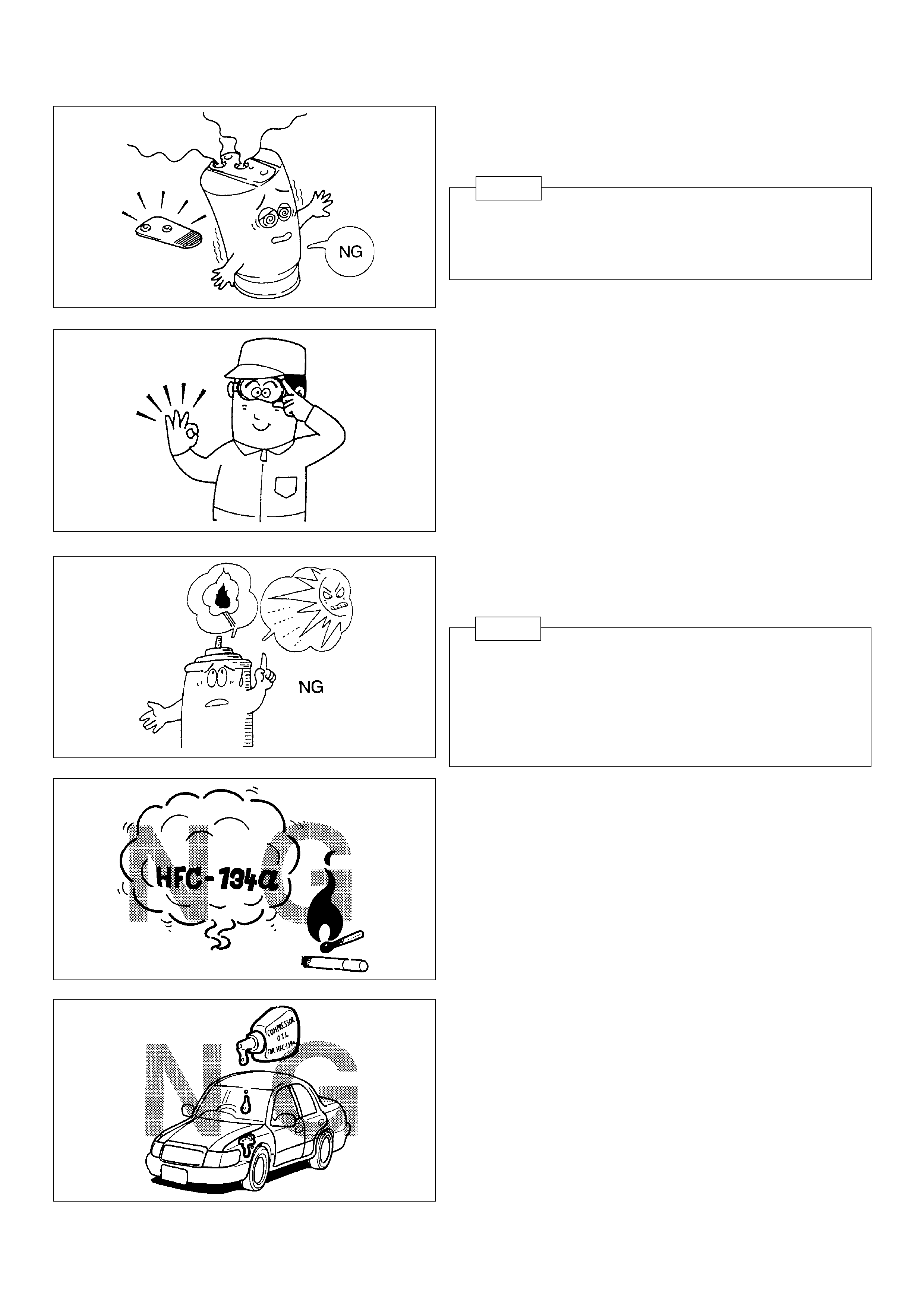
(13)Always keep the refrigerant container (service drum) below
40°C (104 °F).
NOTE
Do not store the refrigerant container in an area where it
can be exposed to direct sunlight, near a source of fire, or
an area such as the inside of a car (the trunk etc.), where
the temperature may become high. Store the container in
a dark place with low-humidity.
(12)When handling refrigerant, always wear proper eye
protection and do not allow it to come in contact with skin.
(14)Do not expose refrigerant to an open flame.
(15)Do not drop compressor oil (ND-OIL 8, 9) onto the vehicle
surface. It causes the discoloration of the vehicle’s body
surface, or deterioration of the acrylic or ABS plastic
components.
– 7 –
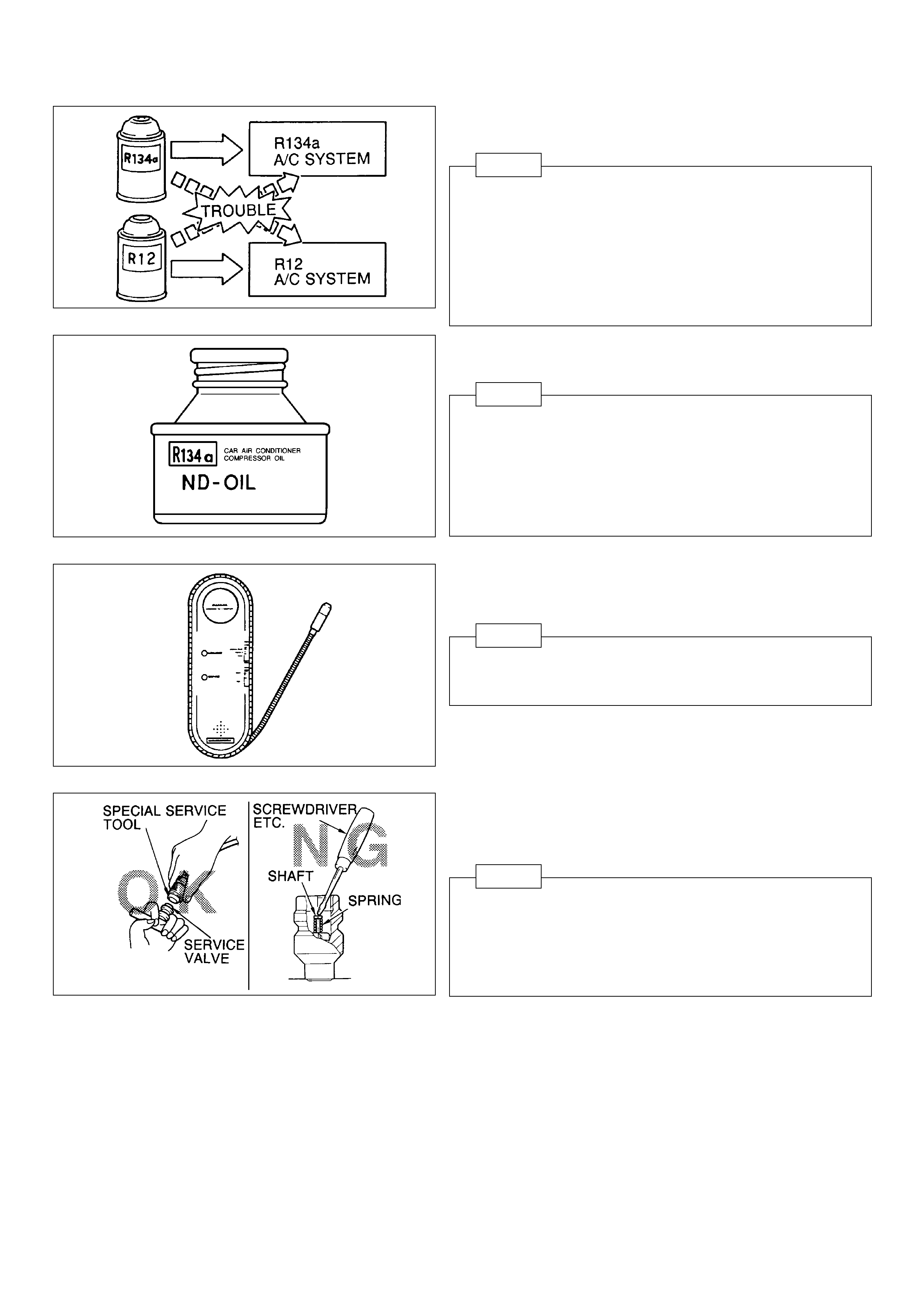
(16)Use the refrigerant HFC-134a (R134a).
NOTE
The very different characteristics of refrigerants HFC-134a
(R134a) and CFC-12 (R12) have determined the design
of their respective air conditioning systems. Under no
circumstances allow CFC-12 (R12) to enter an HFC-134a
(R134a) system, or vice versa, because serious damage
could occur.
(19)When recovering refrigerant, use the necessary special
service tools.
NOTE
1. Support the service valve by hand to prevent the tube
from bending when connecting the charging hose.
2. Using a general tool like a screwdriver may cause
refrigerant leak by damaging the service valves.
(17)Use the correct compressor oil.
NOTE
Compressor oil used in pre 1993 vehicles CFC-12 (R12)
air conditioning systems cannot be used in HFC-134a
(R134a) air conditioning systems.
For a swash plate type compressor : 200PG (ND-OIL 8)
For a vane type compressor: 100PG (ND-OIL 9)
(18)Use HFC-134a (R134a) gas leak detector.
NOTE
The CFC-12 (R12) leak detector is not sensitive enough
to detect HFC-134a (R134a).

– 8 –
(20)Use manifold gauges for HFC-134a (R134a).
NOTE
1. Manifold gauges
Always use HFC-134a (R134a) dedicated manifold
gauges to prevent CFC-12 (R12) and CFC-12 (R12)
compressor oil contaminating the HFC-134a (R134a)
system.
2. Vacuum pump adapter
(1) By connecting a vacuum pump adapter, the vacuum
pump can be used for both HFC-134a (R134a) and
CFC-12 (R12) air conditioning systems.
(2) Be sure to turn off the manifold gauge valve
immediately after evacuating the system, then switch
off the vacuum pump. If this order is reversed, the
line will be temporarily open to atmosphere.
(21)After installing the drive belt, check the belt tension using
a belt tension gauge DENSO BTG-20 or BORROUGHS
BT-33-73F.
NOTE
1. The belt tension must be measured between the
specified pulleys as indicated in the installation manual.
2. A “New belt” refers to a belt which has been used for
less than 5 minutes of operation.
A “Used belt” refers to a belt which has been used for
more than 5 minutes of operation.
3. The drive belt requires accurate tension adjustment ; a
slack belt is likely to cause the belt to whine, while
excessive tension may result in damage to the bearings
or the idle pulley bracket.
4. After installing the drive belt, make sure it is properly
seated in the grooves of the pulley.
– 9 –
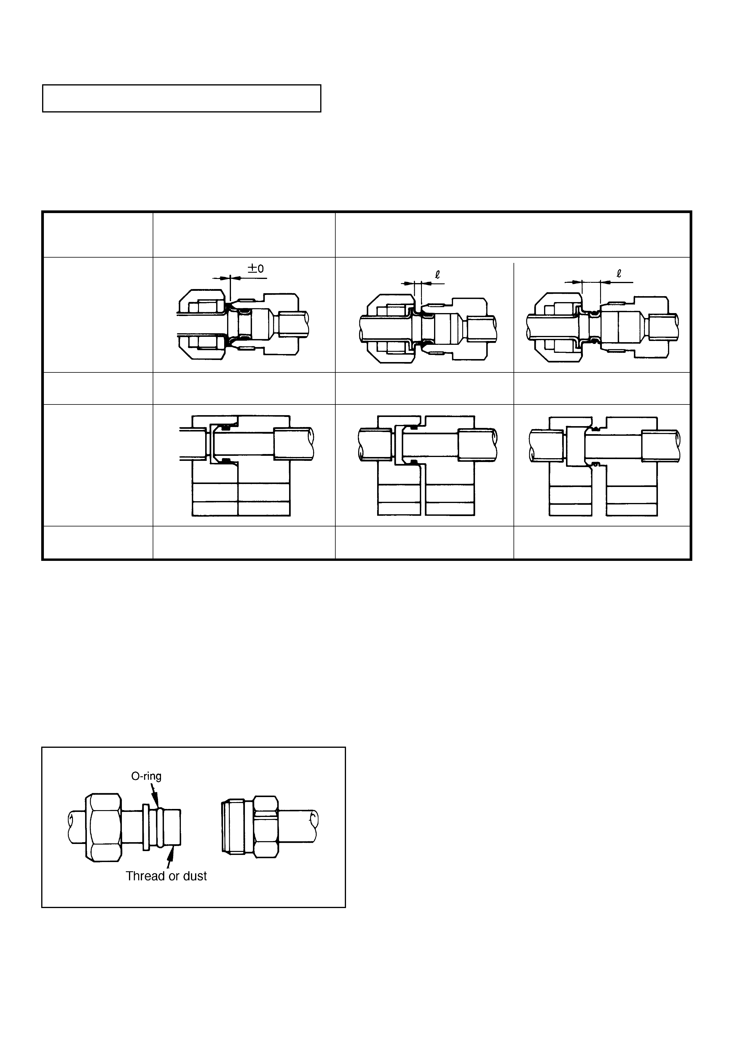
1-5 PIPE JOINT PRECAUTIONS
(1) Common to all pipe joints
(a) When connecting pipes, after complete mating (pre-mating)(see the illustration below) tighten bolts or nuts.
Reason : Installation without complete mating often causes slanted installation, pinched O-rings, or scratches on
seal surfaces.
(d) Check that no dust is on the O-ring mating parts.
Also do not touch O-rings with gloves on.
(b) Always apply the specified compressor oil (*) to an O-ring before installing it. However , when resin (such as acrylic
resin or ABS plastic) is in the area, beware of the possibility that oil causes environment al stress cracking to these
resins. Be careful to prevent foreign materials from contaminating the oil.
(*) 10P-type, 7SB, scroll : ND8 T V-type : ND9
(c) Check that an O-ring is installed correctly before mating joints.
Determination
OK NG NG
Block joint
OK NG NG
Nut union
Complete Mating
(Insert a male part into a female part.)
Incomplete Mating
Determination
l: Incomplete joint (an opening)
– 10 –
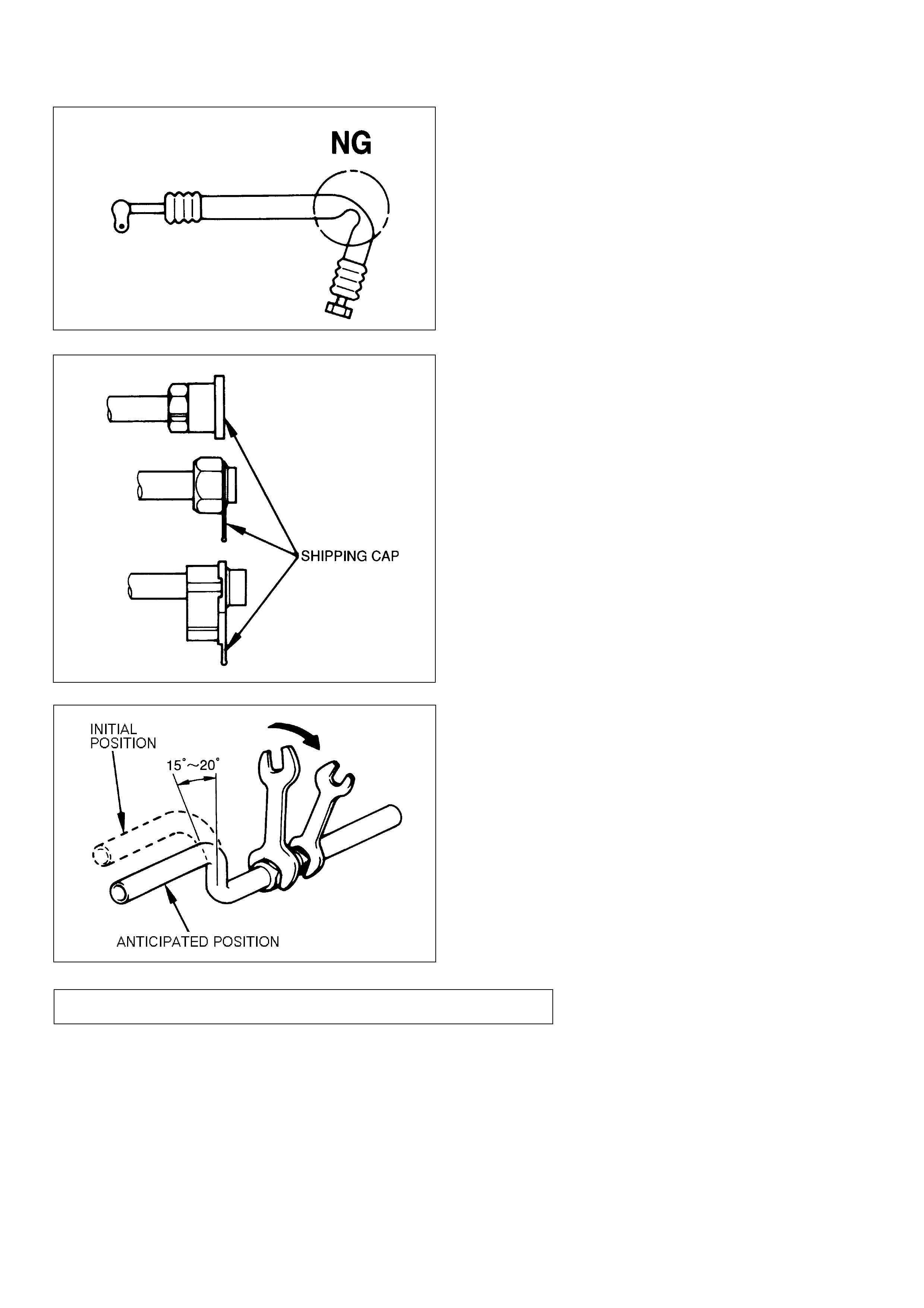
(e) Do not add excessive force to pipes. Do not deform pipes.
(f) Arrange hoses well. For example, it is not allowed to
bend or twist engine mounted hoses.
Reason : Resin inside of hoses may be bent or scratched,
and it may lower the permeation-proof function.
1-6 GENERAL PRECAUTIONS IN ASSEMBLY
(1) Be careful to keep parts, service tools, mating parts of various service equipment (including O-rings) free from
unspecified oil or dust.
(2) Avoid using refrigerant oil (such as ND-8 or ND-9) near painted surfaces and resin materials (acrylic resin, ABS
plastic, or polycarbonate).
(3) Remove a receiver shipping cap only just before mounting (connecting pipes). Also mount a receiver last of all the A/
C system parts, or at least assemble system parts while the receiver shipping cap is removed for only a short time (for
1 hour or less).
(2) Nut union-type
(a) Always assemble pipes using 2 wrenches.
(b) Pipes will rotate from 15° to 20° clockwise during
tightening, so anticipate the displacement caused by
rotation of the nut and then mount pipes.
(c) When finally tightening pipes, do not rotate the fixed side
(the female side).
(g) Remove a shipping cap just before connecting pipes.
Reason : To keep O-rings or O-ring seals from dust.
(h) During air conditioning installation, confirm there is no
interference between the pipes and vehicle parts. (Keep
proper clearances.)

– 11 –
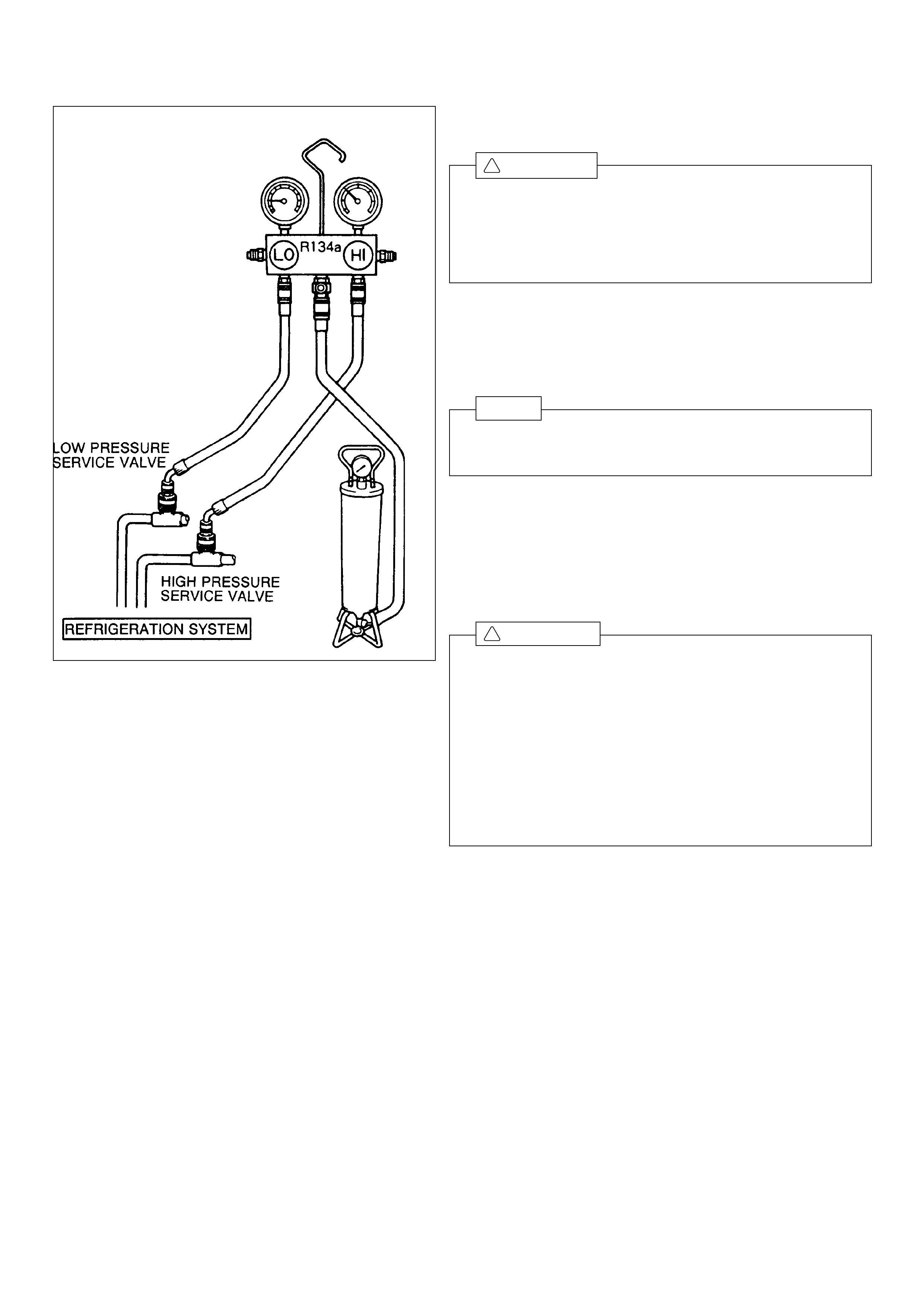
1-7 CHARGING REFRIGERANT (HFC-134a)
(1) Connect the quick disconnect adapters to charging hoses.
(2) Remove the caps from the service valves on the refrigerant
line.
(3) Install the manifold gauge set to the service valves.
(a) Close both high and low pressure valves of manifold
gauge set.
(b) Connect the quick disconnect adapters to the service
valves.
(4) Evacuate air in refrigeration system.
(a) Connect the vacuum pump adapter to the vacuum pump.
(b) Connect the center hose of the manifold gauge set to
the vacuum pump adapter.
(c) Open both the high and low pressure valves and turn
on the vacuum pump.
(d) After ten minutes or more, check that the low pressure
gauge indicates -0.1 Mpa ( -750 mm Hg ) or less.
NOTE
If the reading is not -0.1 Mpa ( -750 mm Hg ) or less,
close both valves of manifold gauge set and stop vacuum
pump.
Check the system for leaks and repair as necessary.
(e) Close both valves and turn off the vacuum pump.
(f) Leave the system in this condition for five minutes or
longer and check that there is no change in the gauge
indicator.
CAUTION
When connecting charging hose to A/C charging valve,
do not use excessive force. Excessive force may damage
charging valves and deform pipes.
!
– 12 –
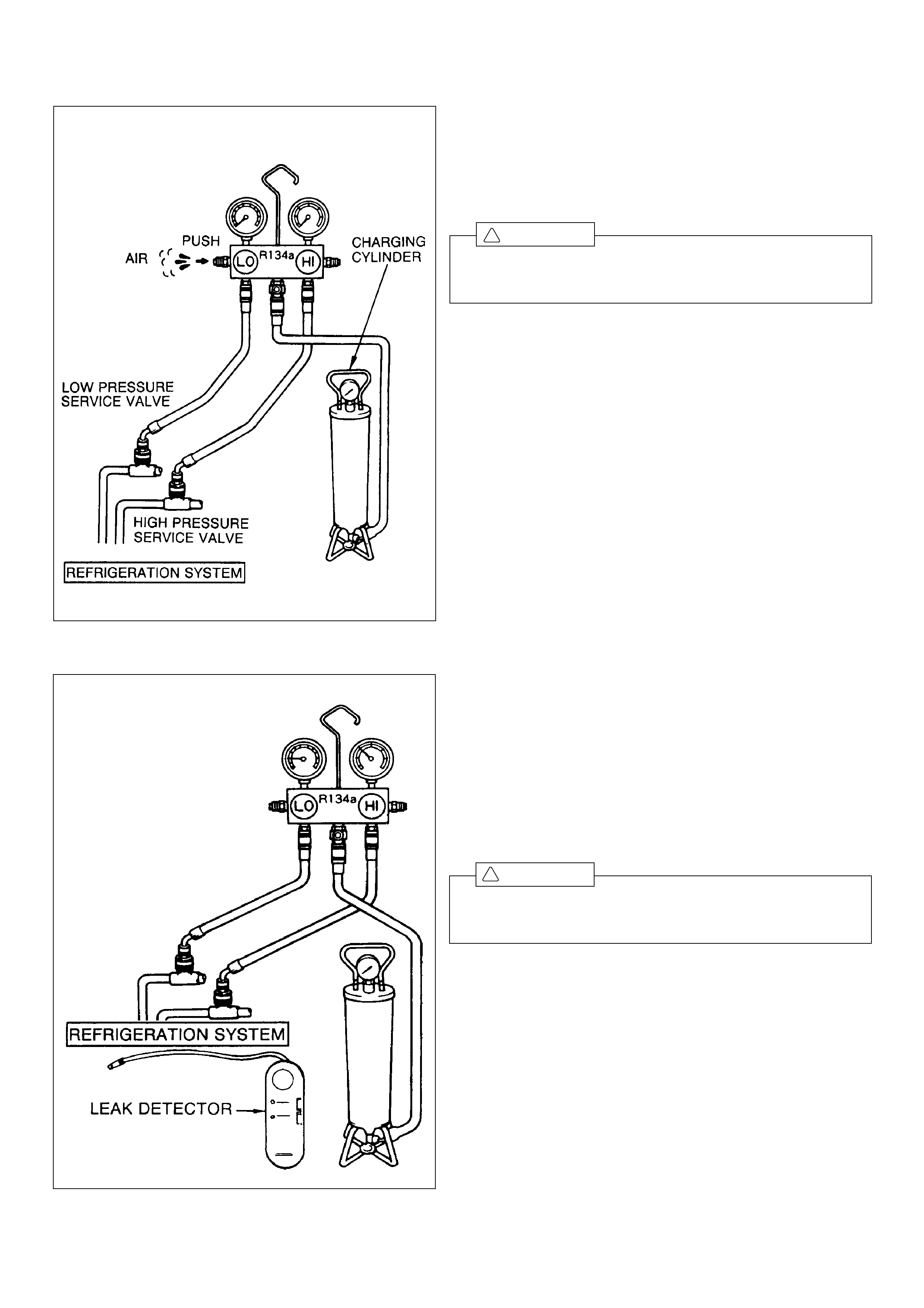
(5) Install charging cylinder.
(a) Charge the proper amount of refrigerant into the charging
cylinder.
(b) Connect the center hose to the charging cylinder.
CAUTION
Do not open both high and low pressure valves of manifold
gauge set at this time.
(c) Open the valve of charging cylinder.
(d) Press the valve core on the side of manifold gauge and
expel the air inside of the center hose.
(6) Inspect the refrigeration cycle for leaks.
(a) Open the high pressure valve and charge refrigerant.
(b) When the low pressure gauge indicates 98 kPa
(1kgf/ cm2, 14 psi), close the high pressure valve.
(c) Using the leak detector, check the cycle for leakage.
(d) If leak is found, repair the faulty component or connection.
And evacuate the air in refrigeration cycle.
CAUTION
Use refrigerant recovery/recycling machine to recover the
refrigerant whenever replacing parts.
!
!
– 13 –
CAUTION
1. After charging refrigerant, be sure to tighten the charg-
ing valve cap.
Recommended tightening torque specification: 0.25
N·m or more
2. If a valve cap is removed, dust or moisture can enter,
and the seal portion on the valve is corroded. This
deteriorates sealing performance, leading to a possible
refrigerant leak.
(7) Charge refrigerant into the refrigeration cycle.
CAUTION
1. Never run the engine when charging the system through
the high pressure side.
2. Do not open the low pressure valve when the cycle is
being charged with liquid refrigerant.
(a) Open the high pressure valve fully.
(b) Charge the specified amount of refrigerant, then close
the high pressure valve.
NOTE
A fully charged system is indicated by the sight glass being
free of any bubbles.
(8) Remove manifold gauge set from service valves.
(a) Close both valves of manifold gauge set.
(b) Disconnect quick disconnect adapters from service
valves.
(9) Install the caps to service valves on the refrigerant line.
!
!
-14-
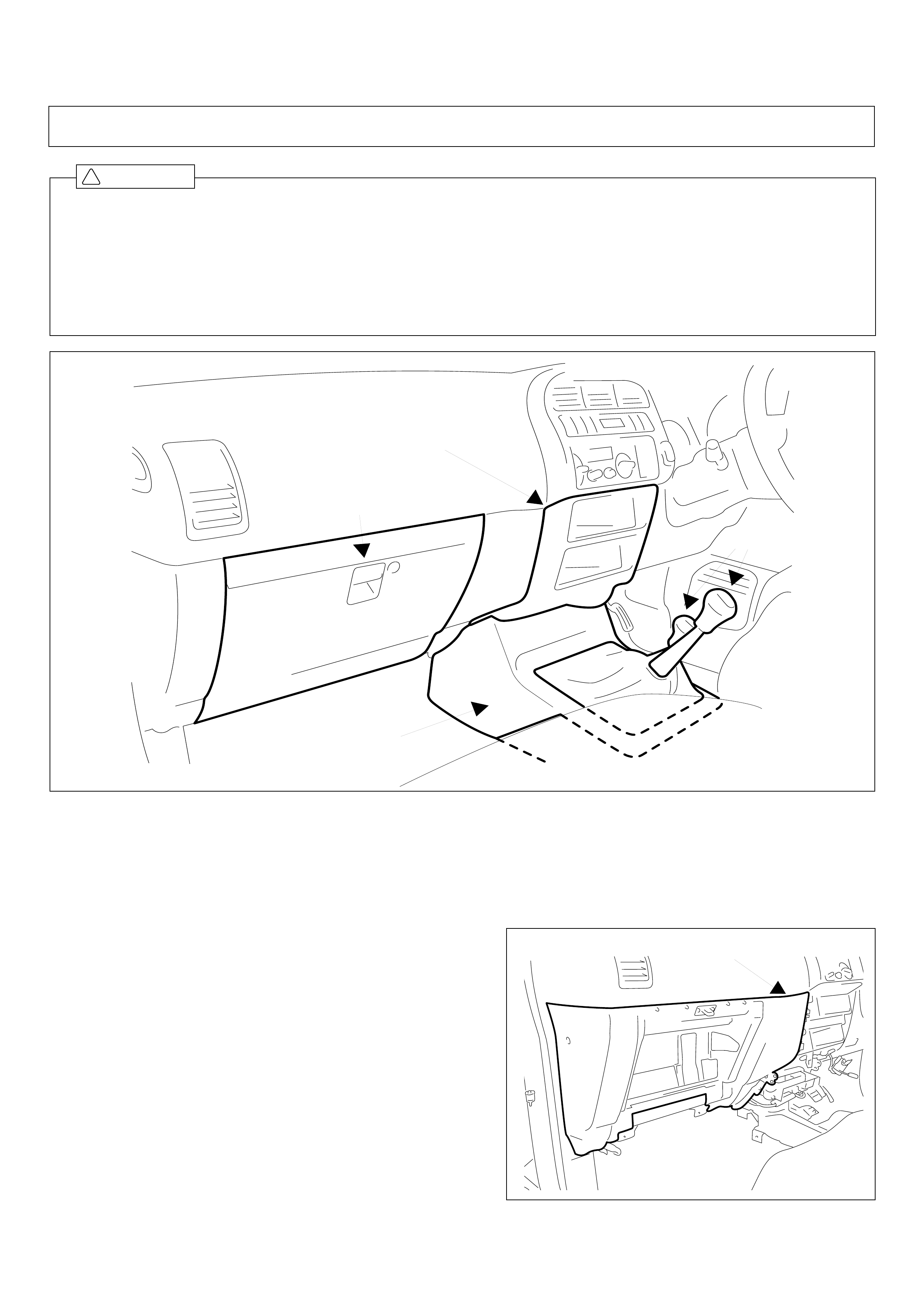
(e) Glove box surround.
NOTE:
Disconnect glove box light.
1. REMOVAL OF PARTS
(a) Glove box.
(b) Gearshift and transfer case knobs (FOR M/T VEHICLES ONLY).
(c) Centre console.
(d) Centre surround.
GLOVE BOX
CENTRE
SURROUND
KNOBS
CENTRE CONSOLE
GLOVE BOX
SURROUND
2. INSTALLATION INSIDE PASSENGER COMPARTMENT
1. Be sure to use the correct oil, refrigerant and charging/recovery equipment.
2. Before starting installation, read all “PRECAUTIONS FOR SAFETY INSTALLATION” thoroughly and follow the
instructions described in it.
3. Before starting installation, remove the (–) terminal of the battery and ensure seat/floor covers are in position.
4. Take care not to scratch any parts of the vehicle.
5. Sort removed bolts and tapping screws into groups so that they can be reassembled correctly.
CAUTION
!
-15-
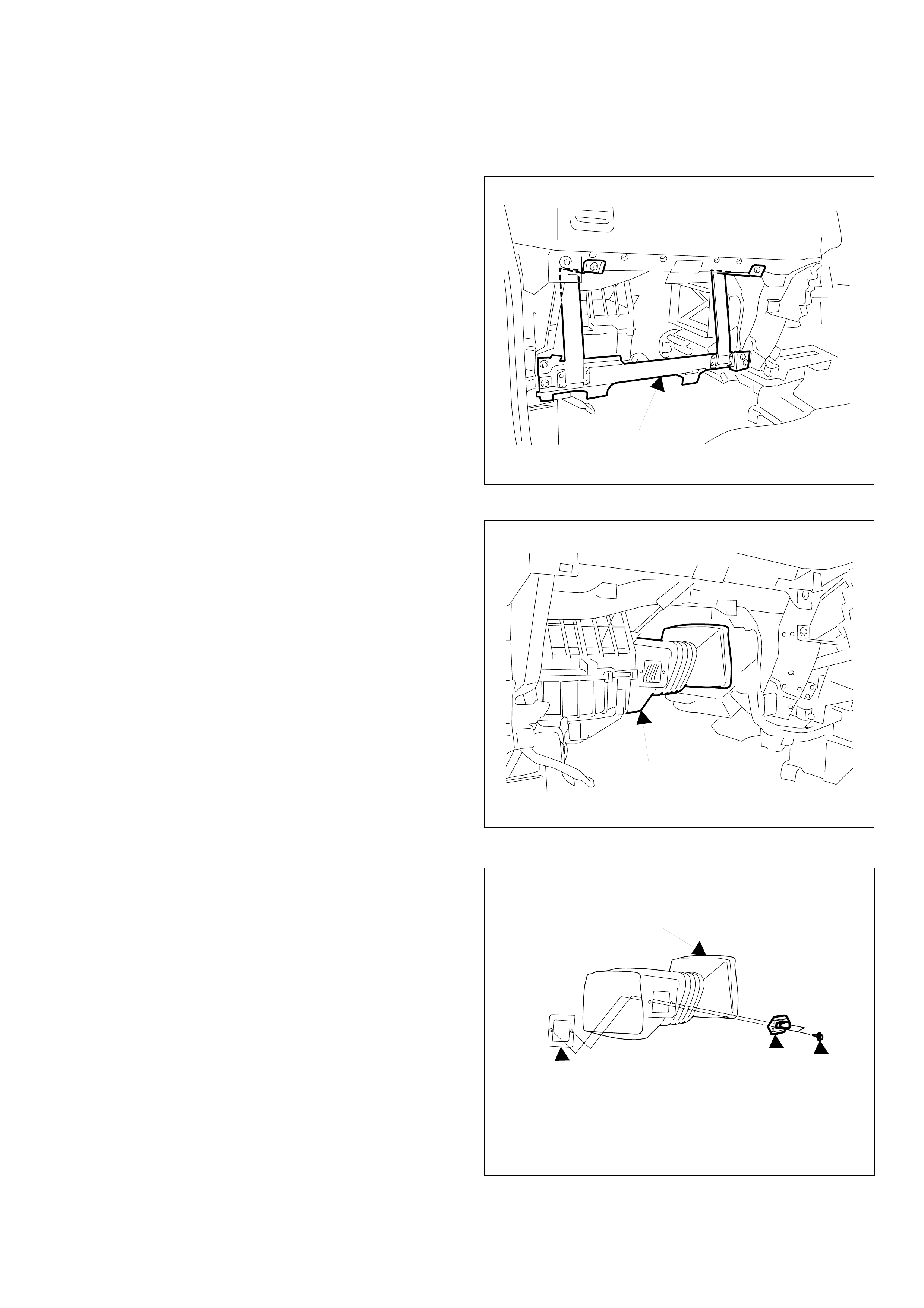
(g) Air duct.
(f) Dash panel support.
(h) Blower resistor and backing plate (reuse).
(i) Air duct (discard).
NOTE:
Blower resistor mounting screws to be reused.
NOTE:
Disconnect blower resistor wire harness.
DASH PANEL
SUPPORT
AIR DUCT
AIR DUCT
(DISCARD)
BACKING PLATE (REUSE) BLOWER
RESISTOR
(REUSE)
SCREW
(REUSE)
-16-
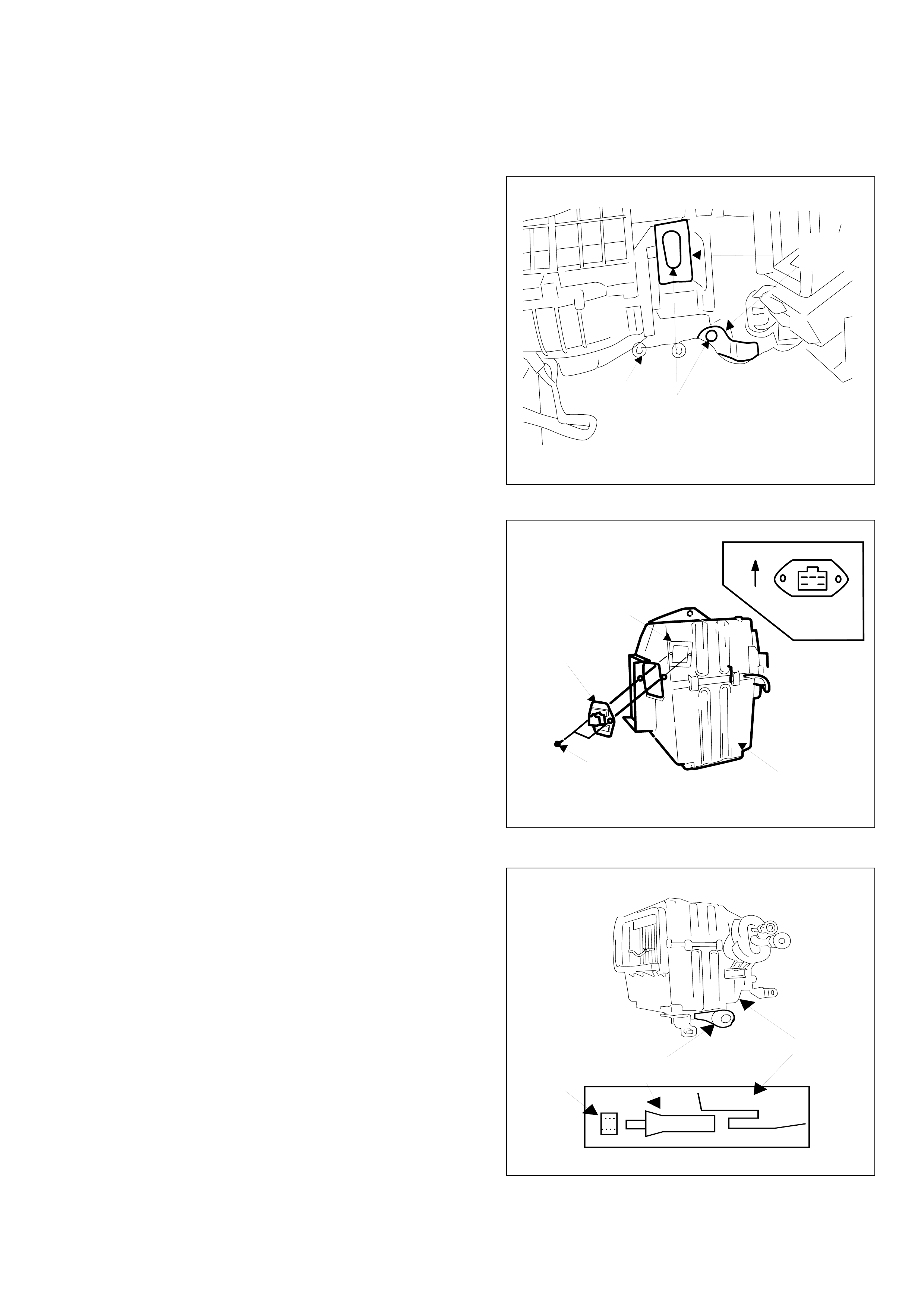
(j) Fire wall grommets and insulation pads.
(k) Original nut (reuse).
2. COOLING UNIT
(a) Assemble blower resistor (reuse) to the
cooling unit using two original screws and
backing plate (reuse).
NOTE:
Make sure orientation of blower resistor is as
shown.
(b) Attach packing to drain hose extension.
(c) Install drain hose extension onto cooling
unit.
INSULATION
PADS
GROMMETS
ORIGINAL NUT
(REUSE)
DRAIN HOSE
EXTENSION
PACKING
COOLING UNIT
COOLING UNIT
BACKING PLATE
(REUSE)
BLOWER
RESISTOR
SCREWS (REUSE)
UPWARD
BLOWER
RESISTOR
-17-
CAUTION:
Ensure drain hose extension is flush with
firewall.
(d) Connect vehicle harness to blower resistor.
(e) Install cooling unit using two washer faced nuts, gold coloured and one original nut (reuse).
(f) Connect A/C harness to vehicle harness (3P) and cooling unit thermostat (5P).
NOTE:
Must install blower resistor vehicle harness prior to installing cooling unit.
COOLING UNIT
THERMOSTAT
NUT
(M6)
(NEW)
NUT (M6)
A/C HARNESS
NUT (M6)
(NEW)
VEHICLE HARNESS
BLOWER RESISTOR
(REUSE)
DRAIN HOSE
EXTENSION
FIREWALL
-18-
(c) Reinstall all temporarily removed parts.
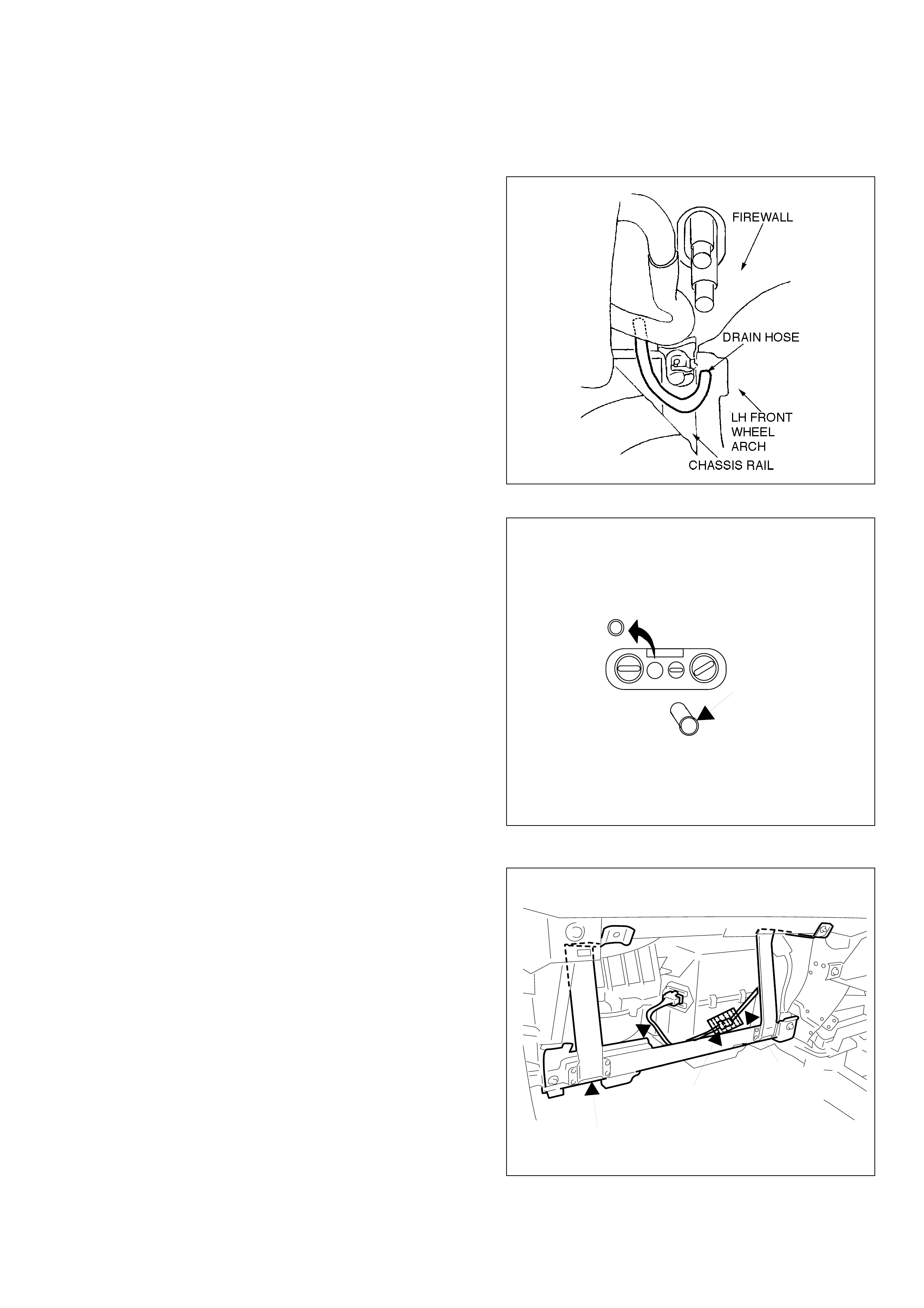
3. A/C SWITCH
(a) Remove A/C switch blanking plate.
(b) Install A/C switch.
4. REINSTALLATION
(a) Attach packing around wire harness
connector as shown.
(b) Reinstall dash panel support bar.
DASH PANEL
SUPPORT
VEHICLE
AND A/C
HARNESS
PACKING
A/C A/C SWITCH
PLATE
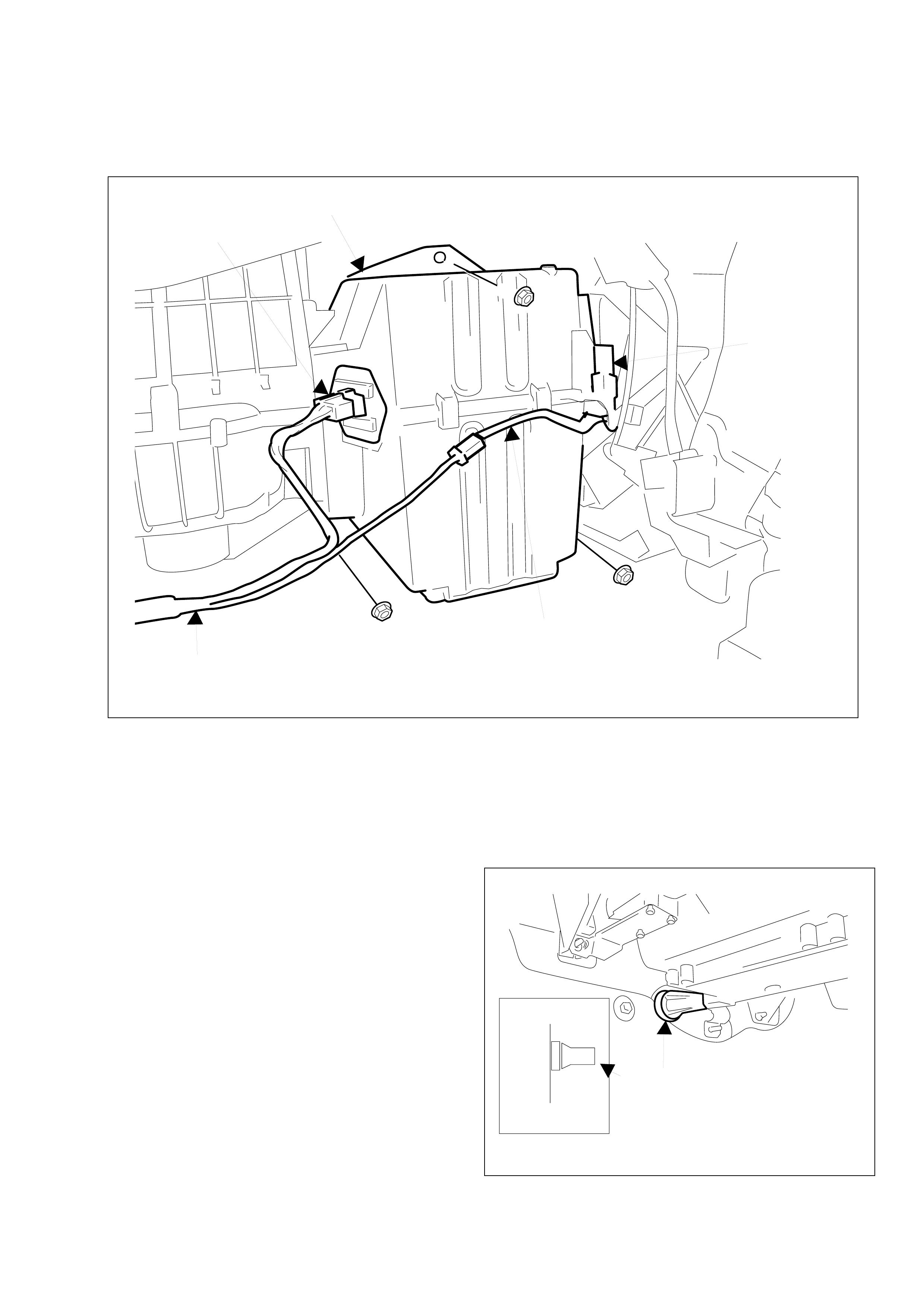
(g) Install drain hose to drain hose extension from
inside engine compartment.
CAUTION:
Ensure drain hose is routed between chasis
rail and body panel and pointing downward and
toward the rear.
-19-
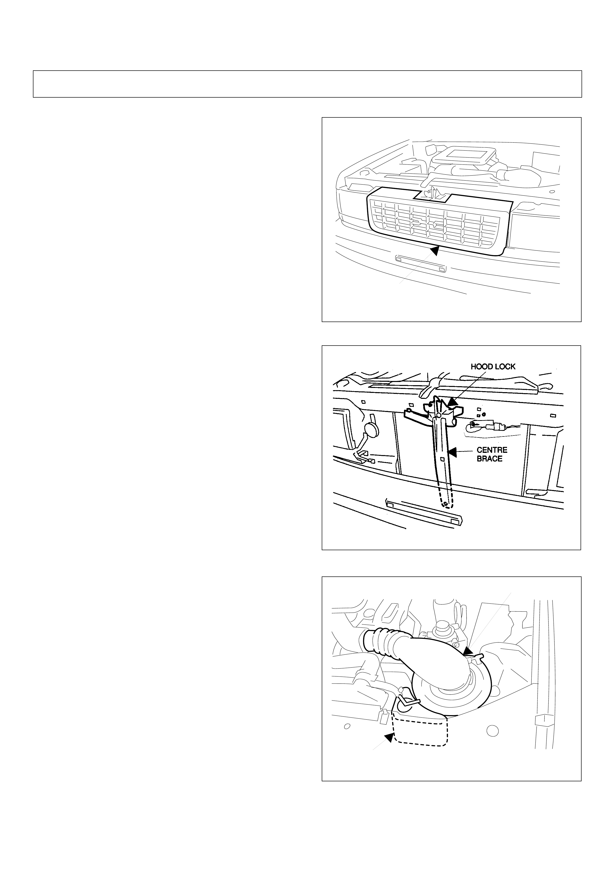
(b) Hood lock.
(c) Centre brace.
NOTE:
Mark out position of hood lock with a pencil
before removal.
• FOR DIESEL E/G VEHICLES ONLY D) - F)
(d) Air inlet assembly.
(e) Radiator overflow bottle.
GRILLE
RADIATOR OVERFLOW
BOTTLE
AIR INLET ASSEMBLY
3. INSTALLATION INSIDE ENGINE COMPARTMENT
1. TEMPORARY REMOVAL
(a) Grille.
-20-
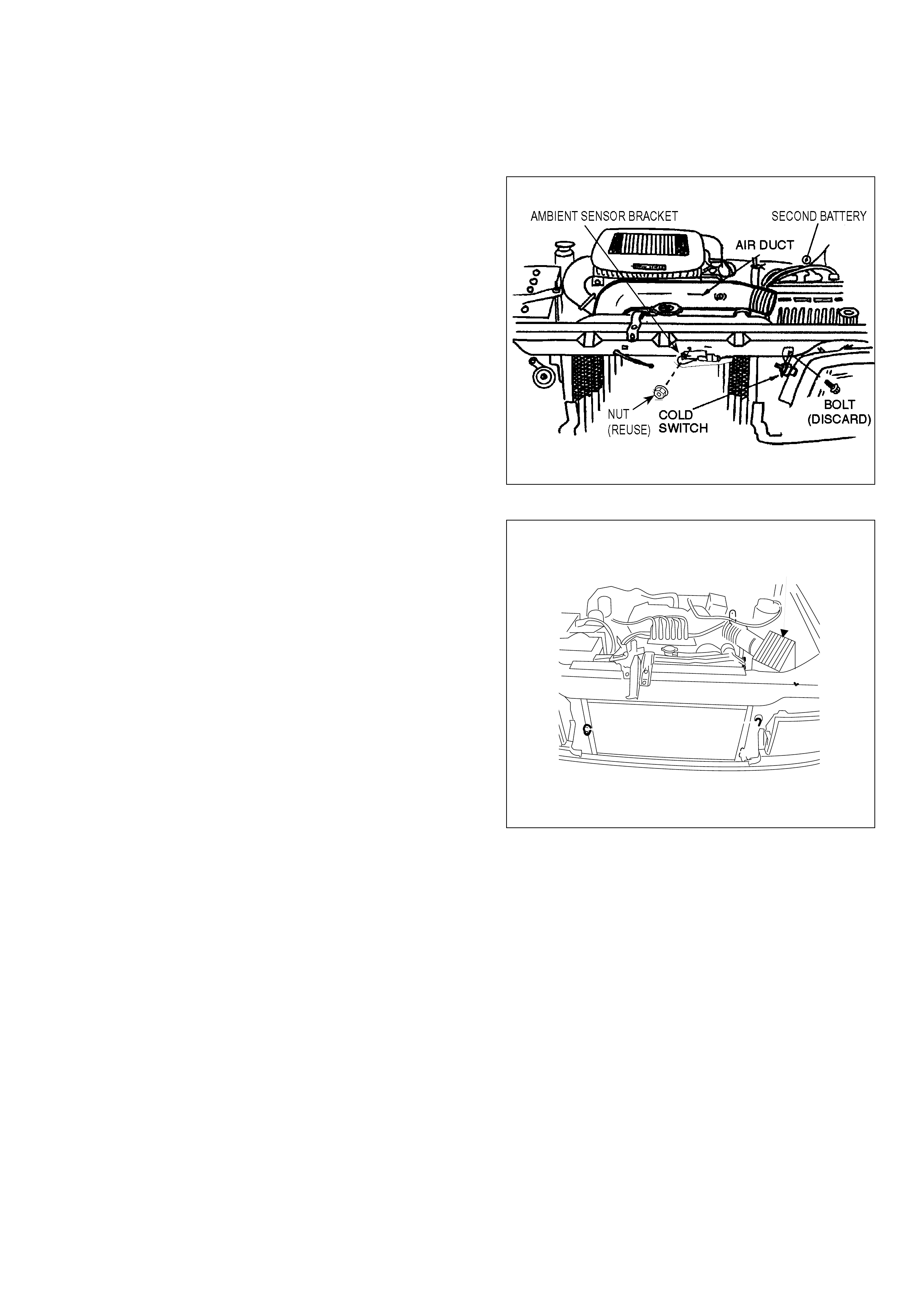
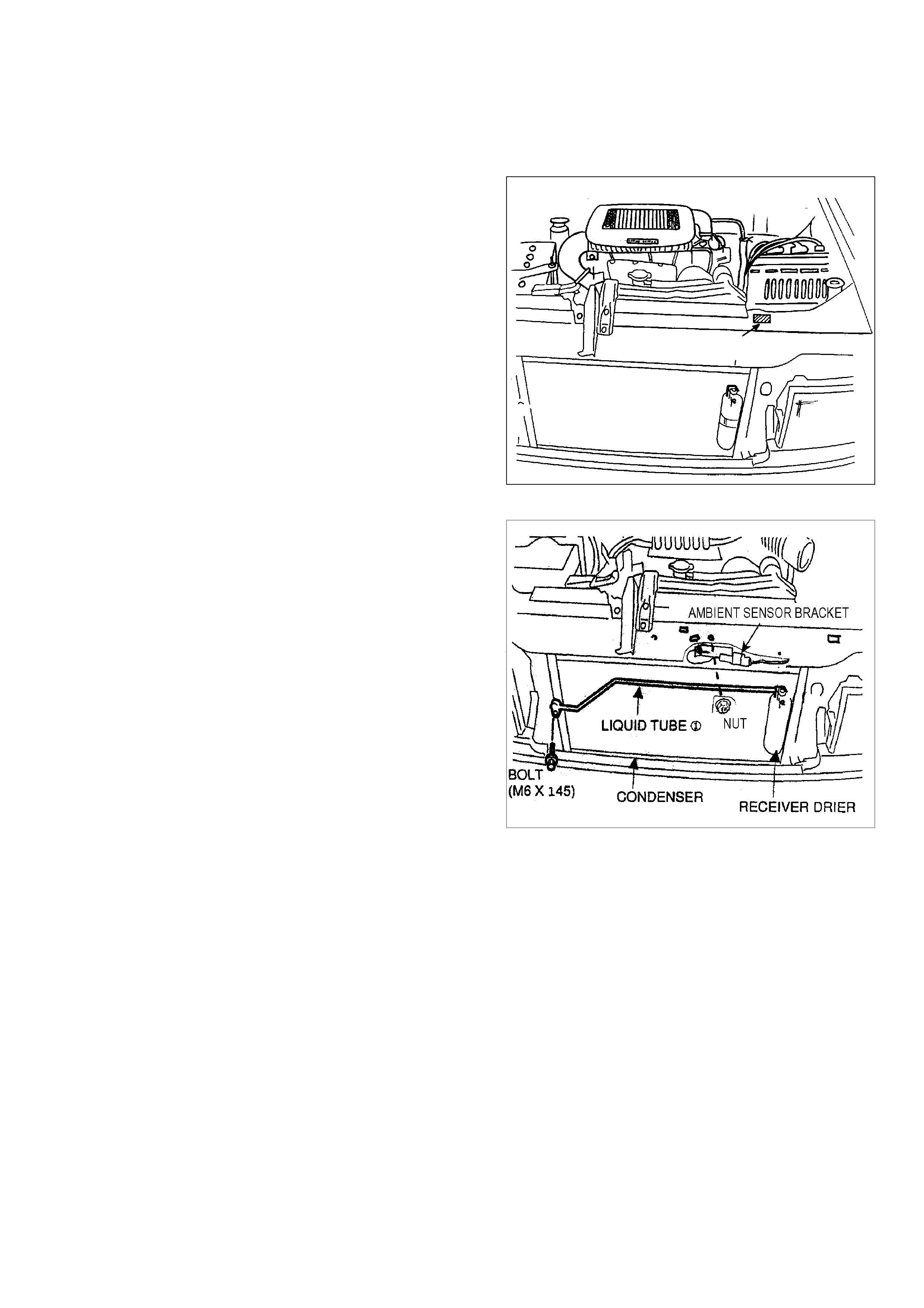
(f) Remove air duct.
( g) Remove bolt from cold start switch (discard bolt).
(h) Cover intercooler with cardboard to preventdamage.
(i) Remove second battery.
(j) Remove and discard original ambient sensor bracket.
•FOR PETROL E/G VEHICLES ONLY G) - H)
(g) Air cleaners assembly.
AIR CLEANER ASSY
-21-
(b) Install condenser using two bolts.
NOTE:
Make sure condenser bushes are located
into cross beam slots.
CAUTION:
Keep clearance more than 20mm
between condenser and horn.
Reposition horn away from condenser if
necessary.
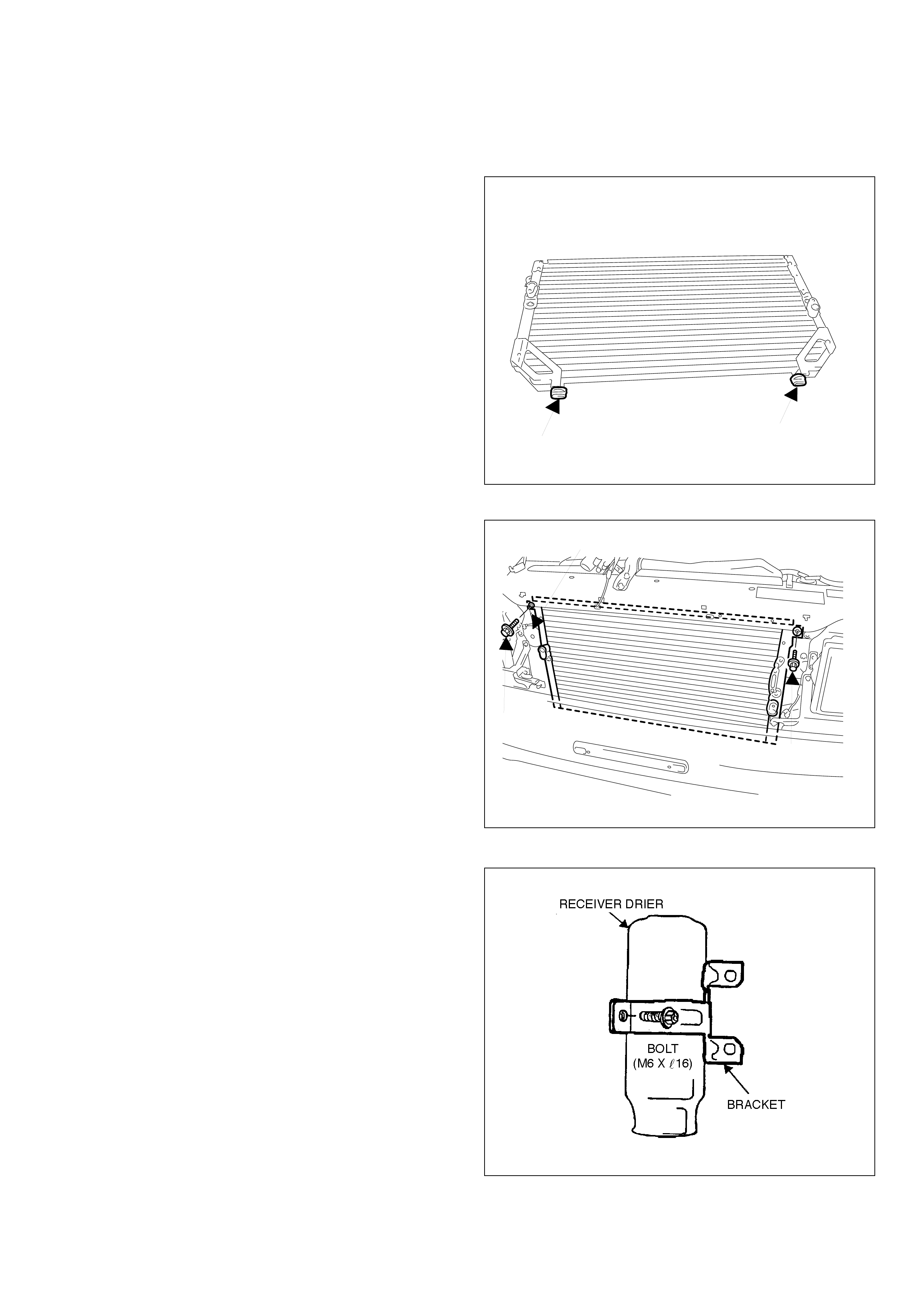
2. CONDENSER
(a) Install bushes onto condenser.
NOTE:
Install onto bottom rear legs of condenser
bracket.
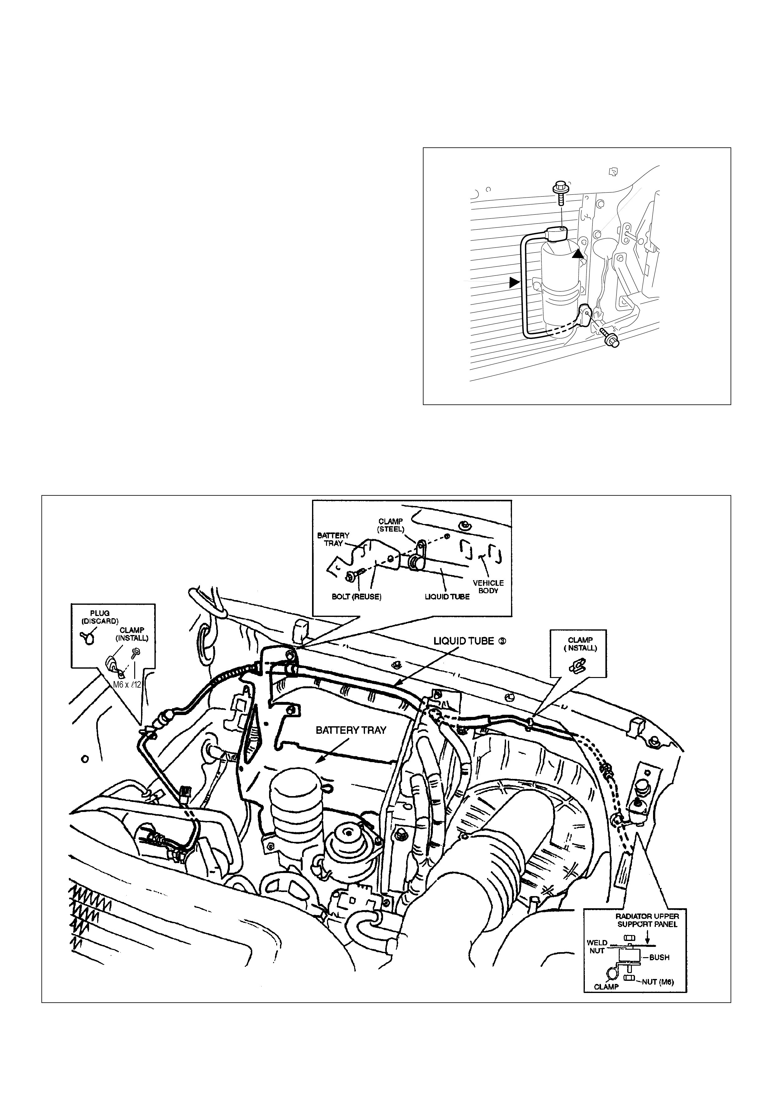
3. RECEIVER DRIER
(a) Loosely assemble bracket onto receiver drier.
BUSH BUSH
BOLT
(M6 X l30)
BOLT
(M6 X l30)
HORN
-22-
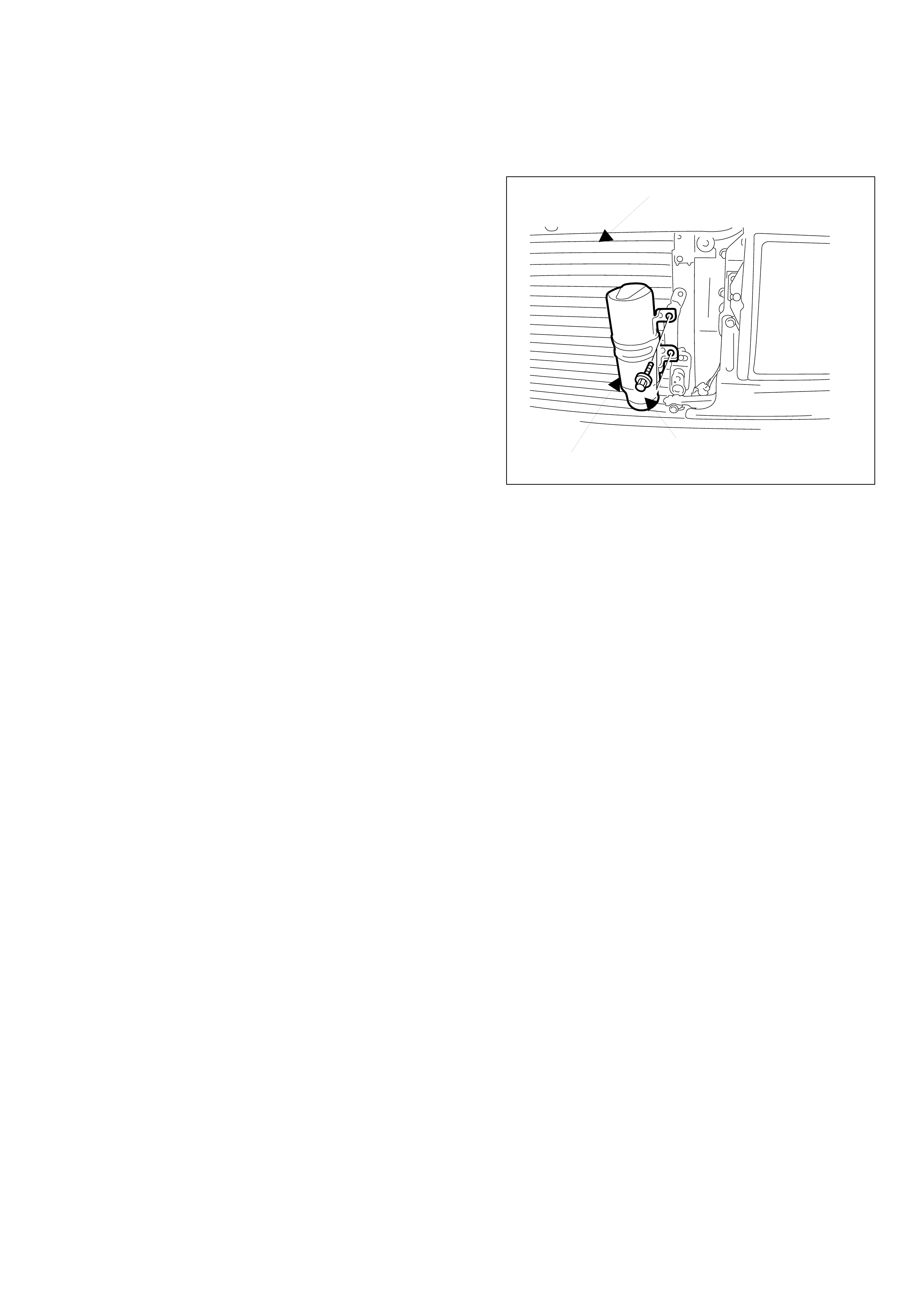
(b) Install receiver drier assembly onto
condenser using two bolts.
CONDENSER
BOLT (M6 X l12)
RECEIVER DRIER ASSY
-23-
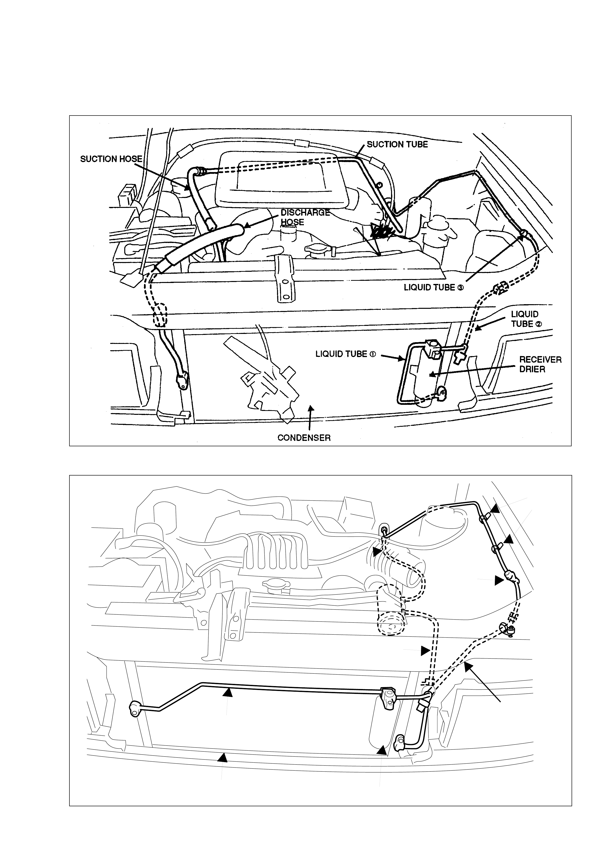
CLAMP
CLAMP
RECEIVER DRIER
CONDENSER
LIQUID TUBE ①
DISCHARGE
HOSE
LIQUID
TUBE ➂
SUCTION
HOSE
LIQUID TUBE ➁
•DIESEL
•PETROL
-24-
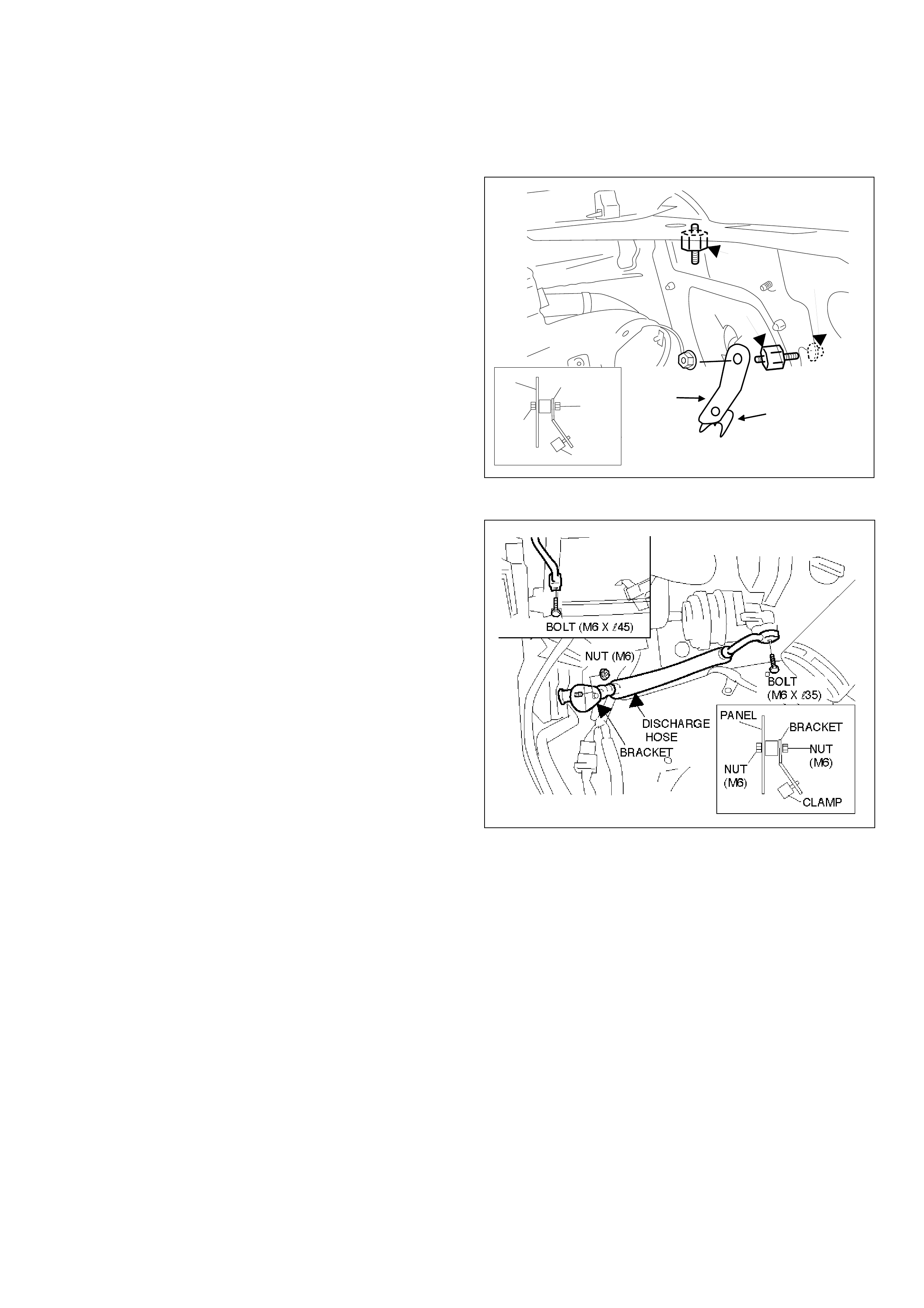
1. DISCHARGE HOSE
(a) Install bush A onto upper radiator support panel.
NOTE:
Use existing weld nut on panel.
•FOR PETROL E/G VEHICLES ONLY (b) - (d)
(b) Install bush B using a nut onto radiator support
panel.
(c) Install clamp onto bracket.
(d) Install bracket to bush B using a nut.
BUSH A
BUSH B
CLAMP
BRACKET
NUT (M6)
NUT (M6)
BRACKET
NUT
(M6)
CLAMP
PANEL
NUT
(M6)
(e) Install discharge hose to compressor and
condenser.
Tightening torque: 10 N.m
( f) Fasten discharge hose using plastic clamp.
-25-
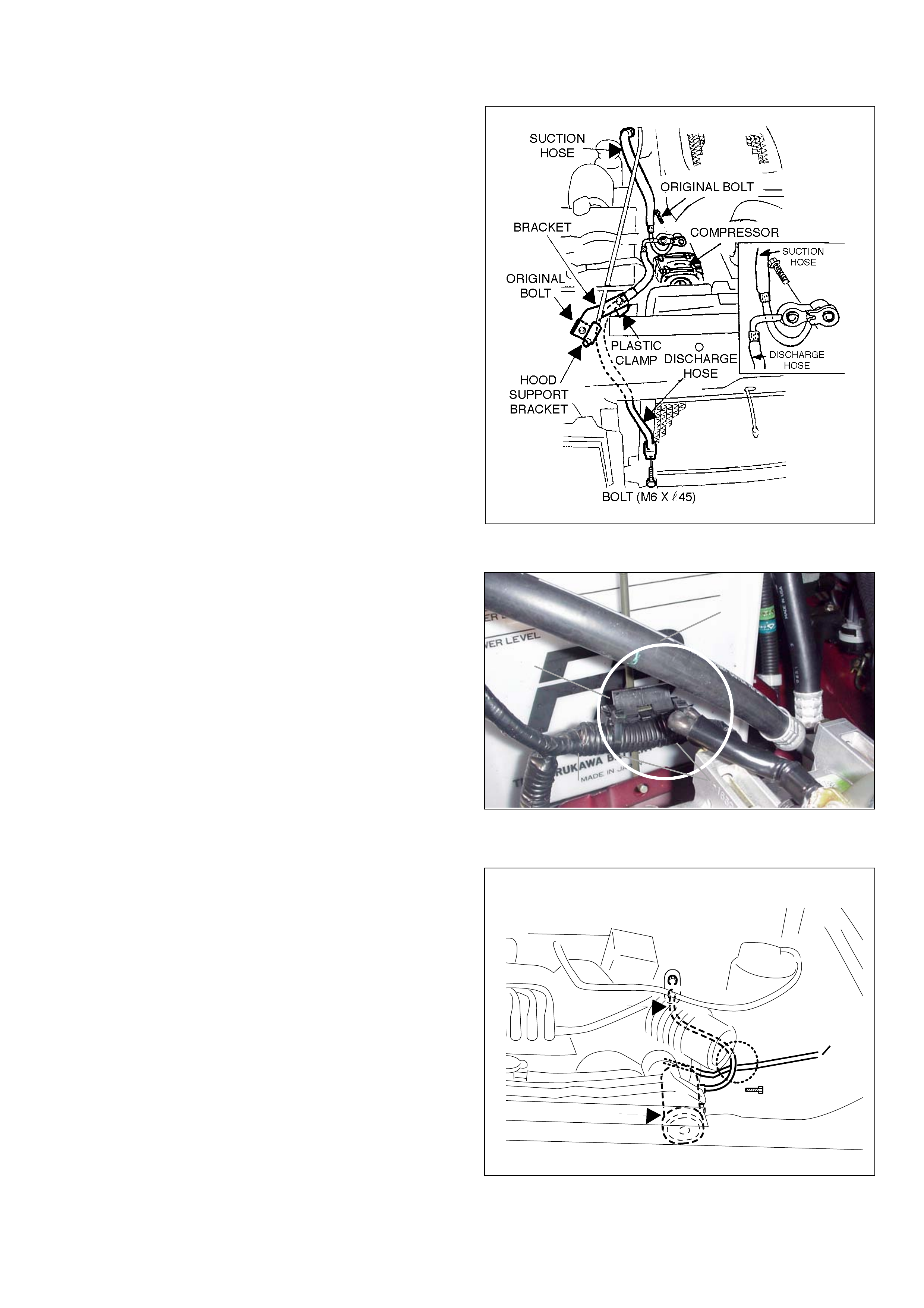
• FOR DIESEL E/G VEHICLES ONLY
(j) Remove compressor cap (do not discard bolt).
(k) Place suction hose to compressor.
(l) Place discharge hose to compressor over the
suction hose fitting.
(m) Fasten both hoses to the compressor using
original bolt.
Tightening torque: 39 N.m
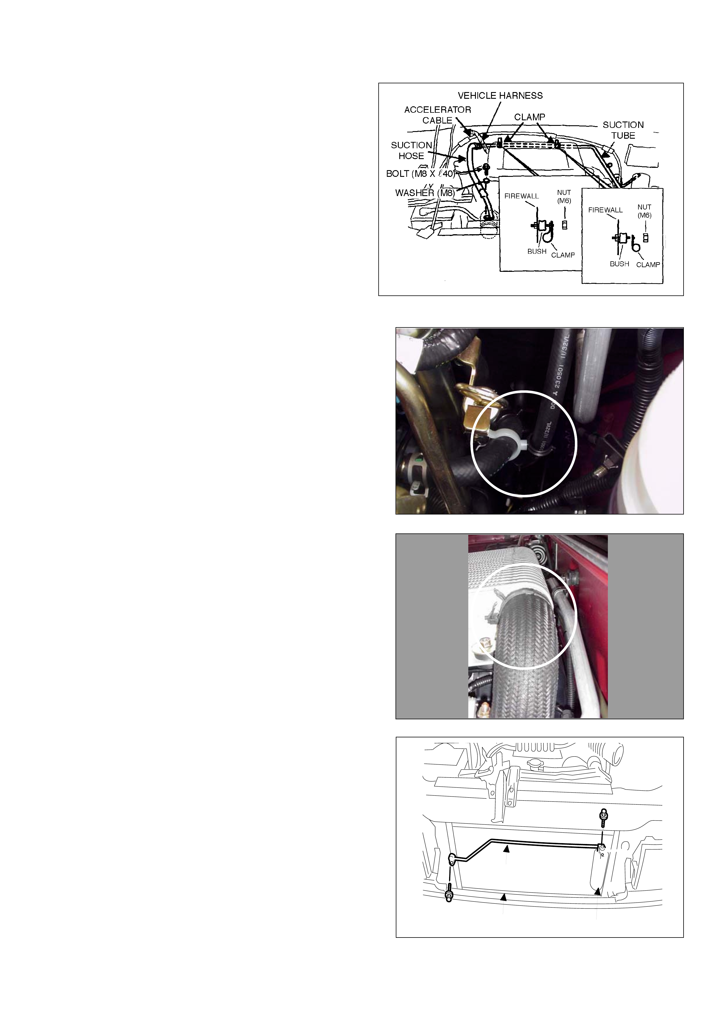
2. SUCTION HOSE
• FOR PETROL E/G VEHICLES ONLY
(a) Install suction hose to compressor and cooling unit.
CAUTION:
Make sure suction hose passes over
vehicle wire harness.
Tightening torque: 10 N.m
SUCTION
HOSE
VEHICLE
WIRE
HARNES
COMPRESSOR
BOLT
(M6 X l35)
CAUTION
(n) Install plastic clamp to the bracket.
(o) Install bracket on top of hood support pole bracket.
CAUTION:
Make sure hood is supported.
(p) Install discharge hose to condenser.
Tightening torque: 10 N.m
CAUTION:
Ensure distance between battery and
discharge hose is minimum 10mm.
(q) Remove two cable ties from harnesses.
(r) Reposition harness below clamp.
(s ) Install two new cable ties to maint ain 10mm
clearance between hose and harness.
▲▲
▲▲
▲
HOSE
▲▲
▲▲
▲
▲▲
▲▲
▲
▲▲
▲▲
▲
▲▲
▲▲
▲
CLAMP
CABLE TIE
HARNESS
-26-
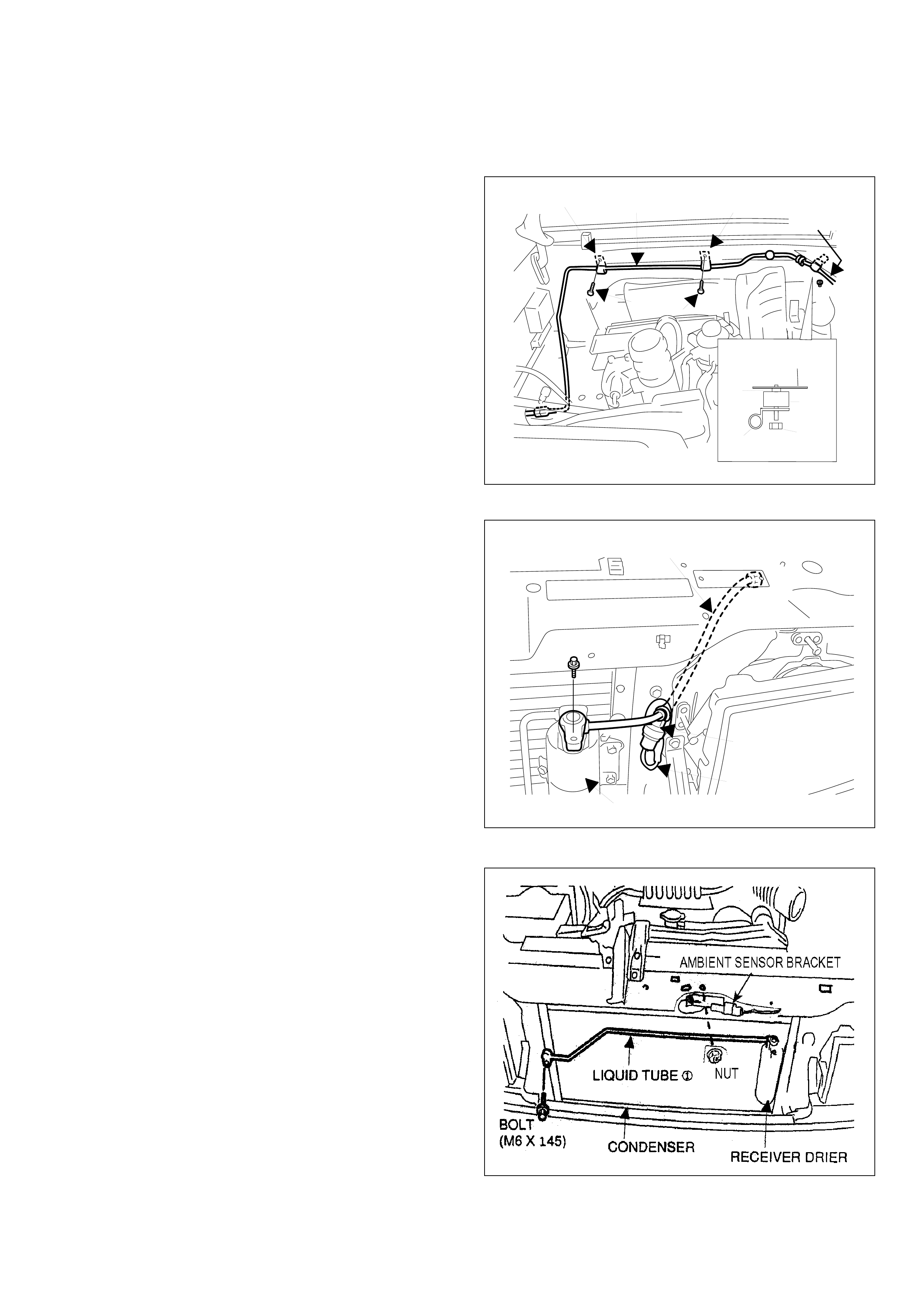
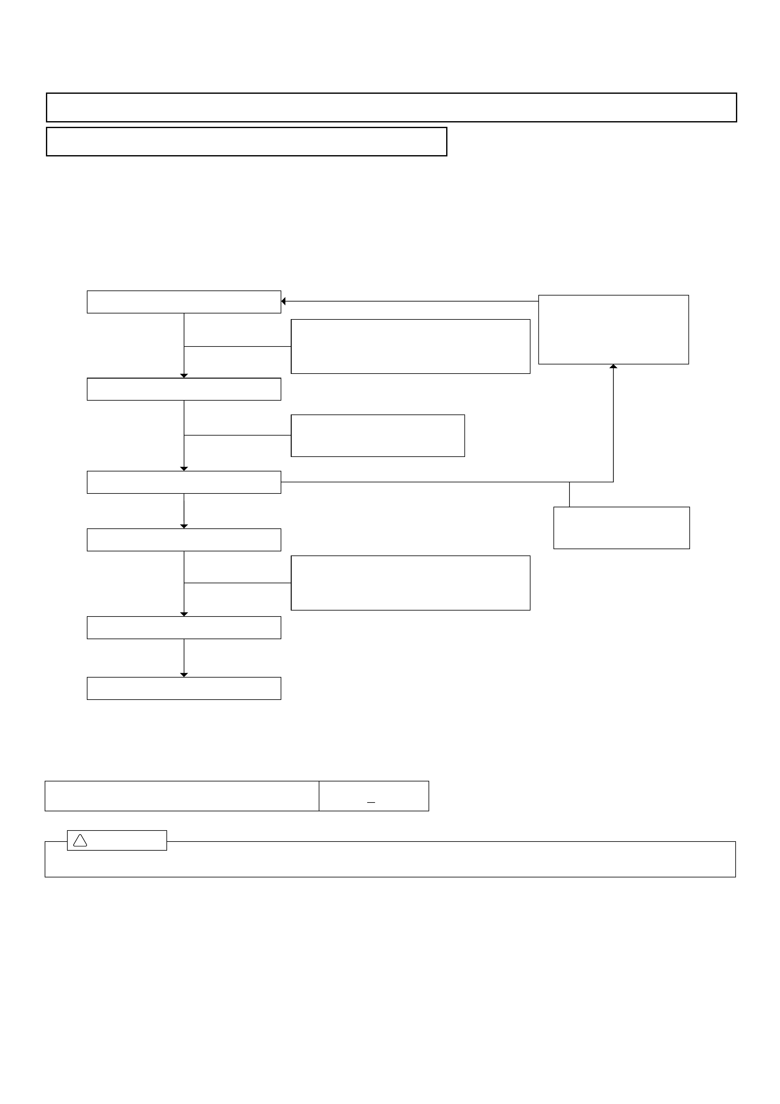
3. LIQUID TUBE
•FOR PETROL E/G VEHICLES ONLY
(a) Install liquid tube 1 to receiver drier and
condenser.
Tightening torque:
Receiver: 5 N.m
Condenser: 10 N.m
(b) Fully tighten receiver drier bracket.
RECEIVER DRIER
CONDENSER
LIQUID TUBE ①
BOLT
(M6 X l25)
BOLT
(M6 X l45)
( f ) Install clamp on heater hose and vacuum hose to
maintain clearance from A/C suction tube.
( g) Rotate hose clamp on intercooler to avoid suction
tube.
•FOR DIESEL E/G VEHICLES ONLY
( b) Install two bushes to firewall.
(c) Route the suction tube under the vehicle harness and
connect to the cooling unit.
Tightening torque:
33 N.m
( d) Fasten the suction tube using two clamps.
( e ) Connect and fully tighten the suction tube to the
suction hose.
Tightening torque:
33 N.m
-27-
•FOR DIESEL E/G VEHICLES ONLY C) - D)
(c) Install liquid tube 1 to receiver drier and
condenser.
Tightening torque:
Receiver: 5 N.m
Condenser: 10 N.m
(d) Fully tighten receiver drier bracket.
RECEIVER DRIER
LIQUID
TUBE ➀
BOLT (M6 X l40)
BOLT (M6 X l25)
( e ) Loosen the bolts holding the second battery tray.
(f ) Install liquid tube 3 to the cooling unit using two plastic clamps and one steel clamp.
NOTE:
Ensure the liquid tube and clamp are mounted between the vehicle body and the battery tray.
-28-
( j) Install liquid tube 2 to liquid tube 3 and
receiver drier.
Tightening torque: 13 N.m
(k) Connect vehicle harness to pressure switch.
NOTE:
Pass harness through radiator support panel
from inside engine compartment.
RECEIVER DRIER
VEHICLE HARNESS
PRESSURE SWITCH
LIQUID TUBE ➁
BOLT (M6 X l25)
•FOR PETROL VEHICLES (g) - (h)
( g ) Install liquid tube 3 to cooling unit.
Tightening torque: 13 N.m
( h ) Fasten liquid tube 3 using two clamps.
( i) Fasten liquid tube 2 using a clamp.
CLAMP LIQUID TUBE ➂CLAMP
NUT (M6)
BOLT
(M6 X l12)
RADIATOR UPPER
SUPPORT PANEL
BUSH
NUT (M6)
CLAMP
WELD
NUT
LIQUID
TUBE ➁
(l) Install ambient sensor to the new bracket supplied.
( m) Ensure harness is clipped on.
( n ) Reuse the nut and the supplied bolt mount on the
bracket to radiator support as shown.
-29-
5. A/C SYSTEM LABEL
(a) Install A/C system label as shown.
( b ) Install ambient sensor to the new bracket supplied.
(c ) Ensure harness is clipped on.
( d ) Reuse the nut and the supplied bolt mount on the
bracket to radiator support as shown.
A/C SYSTEM LABEL
– 30 –
4. AFTER INSTALLATION
4-1 CHARGING REFRIGERANT (HFC-134a)
(1) Automatic charging machine
Before evacuating air or charging refrigerant using the automatic charging machine, read the relevant manuals
thoroughly.
(2) Charging cylinder
When charging refrigerant using a charging cylinder, evacuate air then charge refrigerant as described below.
Charge gaseous refrigerant from Hi
pressure side until the Low pressure
gauge indicates 0.098Mpa (1kgf/cm2).
START EVACUATION
STOP EVACUATION
Leave the system with this
conditioning for 5 minutes.
CHECK FOR AIR LEAKAGE
CHARGE REFRIGERANT
CHECK FOR GAS LEAKAGE
CHARGE REFRIGERANT
CHECK AND CORRECT
EACH CONNECTION
The gauge indicates
abnormal level.
Evacuating time: 10 minutes
Evacuating pressure: 270 pa or less
(–750mmHg)
CAUTION
Ensure to fill the refrigerant to the specified amount.
!
STANDARD AMOUNT OF REFRIGERANT 650 + 50g
– 31 –
4-2 FINAL LEAKAGE CHECK
This description is provided here as a reference for the checking procedure. When the air conditioner is installed it is
important to fill the specified amount of refrigerant. When checking the refrigerant amount during repairs, for example,
consult the vehicle repair manual.
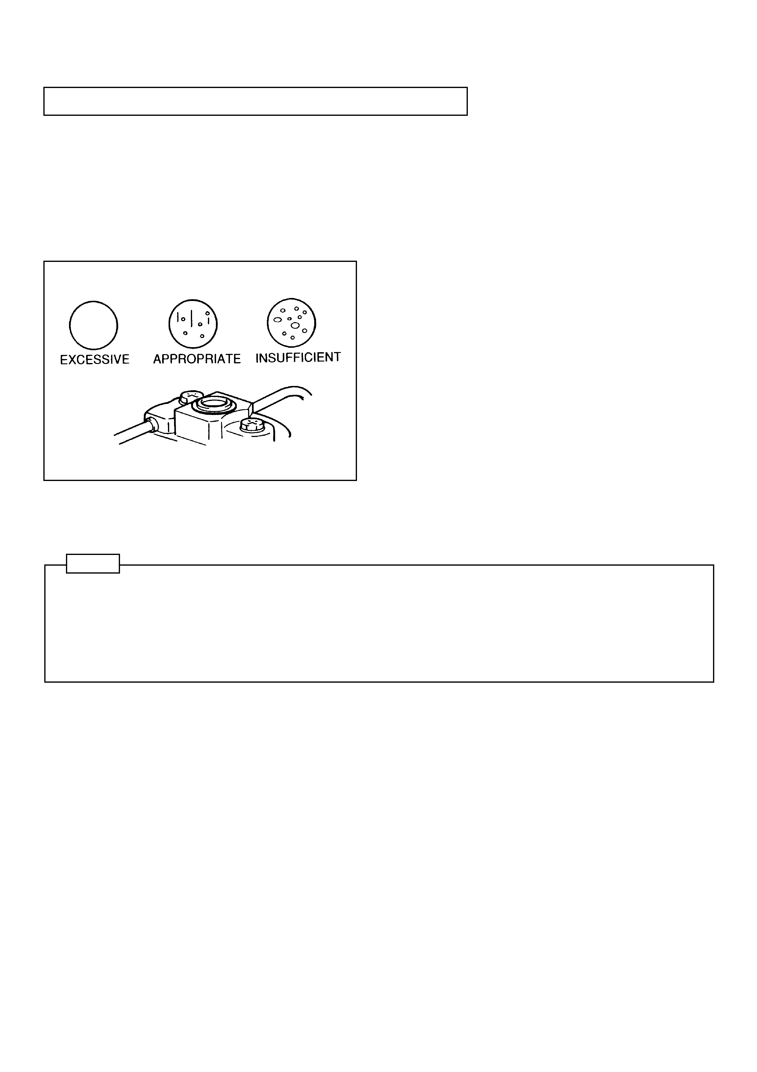
(1) Check refrigerant amount through the sight glass.
(a) Set the following conditions
Engine speed...Idling
In case of dual type A/C...Switch both front and rear ON.
(b) Visually check a sight glass under the following
conditions.
Appropriate...Almost no bubbles
(Idling speed : After gradually increasing
speed, bubbles disappear at 1500 rpm.)
Excessive...No bubbles
(Pressures on both the high and low side
are high.)
Insufficient...Continuous bubble occurrence
NOTE
1. Pressure on the high pressure side when charging refrigerant should be 19 kg/cm (1.87 Mpa) or less. When
outside air temperature is high (40 °C or more) and if the pressure becomes more than 19 kg/cm (1.87 Mpa),
perform the check in a cool place with all the doors open and with the blower speed set to LO.
2. When an electric fan starts with an appropriate refrigerant level, bubbles might appear temporarily. (For about 5
seconds)
(2) In case of a 'low charge' above, there may be a leak. Then, check joint areas of each part with a leak tester , and repair
the leak.
2
2

– 32 –
4-3 RE-ADJUSTMENT OF COMPRESSOR BELT
+0.5
–0 +5
–0
Refer to the vehicle's manual for correct belt tension. Keep in mind that initially after five minutes of A/C operation, the belt
is likely to elongate.
Retension the belt if necessary after A/C operation and check.
4-5 RESTORE THE VEHICLE
Reinstall all the parts of vehicle that have between temporarily removed.
!CAUTION
1. In particular, improper installation of instrument panel’s parts, improper tightening of tapping screws or loose
connectors may cause abnormal noise. Therefore make sure that they are installed or fastened properly to avoid
abnormal noise that can occur after the air conditioning installation is complete.
Tightening torque for tapping screw ....................... 1.5 N·m (15 kgf·cm)
Tightening torque for cross recessed head bolt ..... 3.4 ± 1.4 N·m (35 ± 15 kgf·cm)
2. If the hole for a tapping screws is too large, use a tapping screw one-size larger.
3. Reinstall each part with particular care so that its clips, guides bosses fit in the specified positions.
4. When installing the instrument panel, make sure that wire harness is not pulled, pushed excessively or trapped.
4-4 ADJUSTMENT OF ENGINE IDLING SPEED
!CAUTION
The engine revolution is controlled by a computer, therefore adjustment is not required. (When the air conditioning
system is started, check whether idling revolution increases.

– 33 –
No.
1
2
3
4
5
6
ITEM
Activation of Magnetic Clutch
Blower Motor Speed Change
Air Outlet Change
FRS/REC. Change
Temperature Adjustment
Condenser fan
DESCRIPTION
ON/OFF
Lo to Hi
Lever Operation
Lever Operation
COOL to HOT
Operation
4-6 FINAL INSPECTION (SAFETY CHECK)
After installing the air conditioning, check for safety and operation of each section shown below.
(1) Inspection after completion of installation
DESCRIPTION
Install and fasten properly.
Do not pinch harness. Make sure connectors are secure.
Do not bend excessively, pinch or constrict.
Maintain specified or in excess of that specified in the installation manual.
There should be no abnormal noise during operation.
CHECK
CHECK
(2) Check for operation of the air conditioning unit
ITEM
A/C Parts
Wiring
Vacuum Hoses
Safety Gaps
Compressor
No.
1
2
3
4
5
CHECK CHECK
CHECK
(3) Check for operation of each electrical component in the vehicle (To be carried out before and after inst allation of the
air conditioning unit)
Horn
Washer
Wipers
Inside lights
Cigarette lighter
Clock
Radio
Blower Motor
Back up lights
ITEM
Turn Signals
Flashers
Head lights
Stop lights
Tail lights
CHECK ITEM
ITEM Before After
AfterBefore Before After
THE AIR CONDITIONER IS NOW READY FOR USE. BE SURE TO EXPLAIN OPERATION TO THE
OWNER.