
GENERAL DESCRIPTION
“Front End Alignment” refers to the angular relationship between the front wheels, the front suspension
attaching parts and the ground.
Proper front end alignment must be maintained in order to insure efficient steering, good directional
stability and to prevent abnormal tire wear.
The most important factors of front end alignment are wheel toe-in, wheel camber and axle caster.
DEFINITION OF TERMS
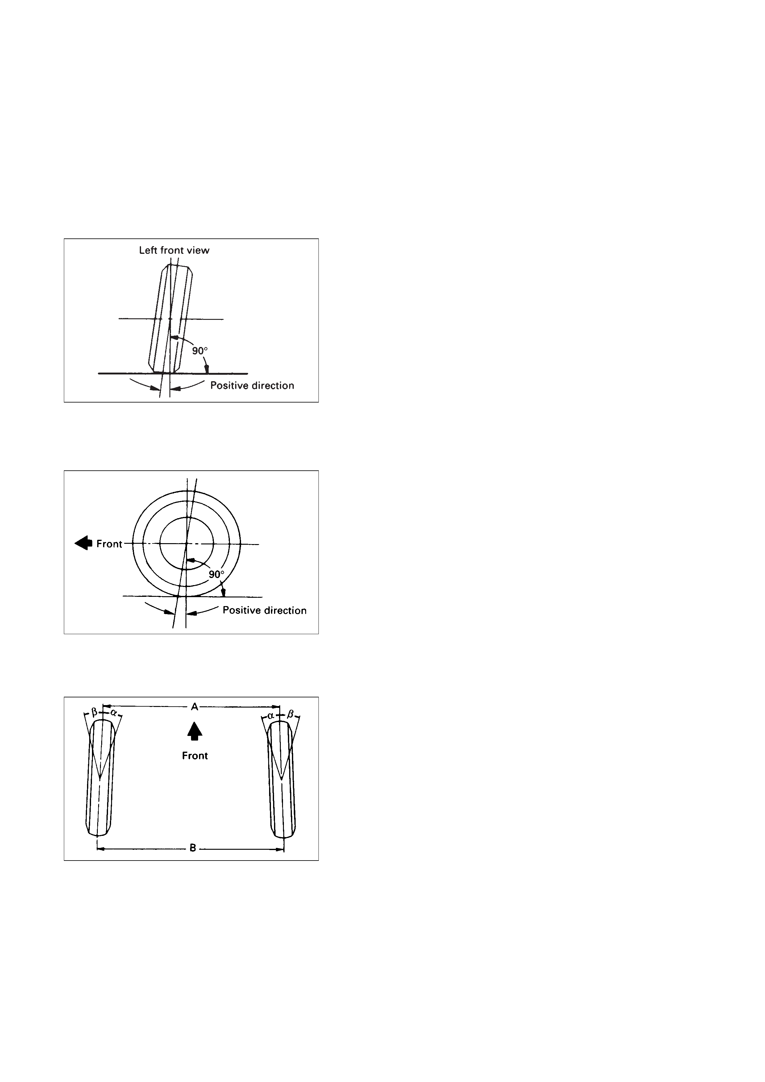
CAMBER
Camber is the inward or outward tilting of the front wheels
from the vertical. When the wheels tilt outward at the top,
the camber is positive (+). When the wheels tilt inward at
the top, the camber is negative (–). The amount of tilt
measured in degrees from the vertical is called the camber
angle.
If camber is extreme or unequal between the wheels,
improper steering and excessive tire wear will result.
Negative camber causes wear on the inside tire, while
positive camber causes wear to the outside.
CASTER
Caster is the tilting of the wheel axis either forward or
backward from the vertical (when viewed from the side of
the vehicle). A backward tilt is positive(+) and a forward tilt
is negative(–).
On the short and long arm type suspension you cannot
see a caster angle without a special instrument, but if you
look straight down from the top of the upper control arm
to the ground, the ball joints do not line up (fore and aft)
when a caster angle other than 0 degree is present. With a
positive angle, the lower ball joint would be slightly ahead
(toward the front of the vehicle) of the upper ball joint
center line.
TOE-IN
Toe-in is the turning of the front wheels. The actual
amount of toe-in is normally a fraction of a degree. Toe-in
is measured from the center of the tire treads or from the
inside of the tires. The purpose of toe-in is to insure
parallel rolling of the front wheels and to offset any small
deflections of the wheel support system which occurs
when the vehicle is rolling forward. Incorrect toe-in results
in excessive toe-in and unstable steering. Toe-in is the last
alignment to be set in the front end alignment procedure.
INSPECTION
Before making any adjustments affecting caster, camber
or toe-in, the following front end inspection should be
made.
INSPECT
1.Tyres for proper inflation pressure. Refer to "Wheels
and Tyres" in section .
2. Front wheel bearings for proper adjustment. Refer to
"Front Wheel Drive" in section 4B.
3. Ball joints, tie rod ends and relay rods. If excessive
looseness is noted, correct before adjusting. Refer to
"Steering Linkage" in section 9B.
4. Wheel and tires for run-out. Refer to "Wheels and
Tyres" section 10.
5. Trim height. If not within specifications, the
correction must be made before adjusting caster.
6. Steering gear for looseness at the frame.
7. Shock absorbers for leaks or any noticeable noise.
Refer to "Front Suspension" in section 3B.
8. Control arms or stabilizer bar attachment for
looseness. Refer to "Front Suspension" in section 3B.
9. Alignment equipment. Follow the manufacturers
instructions.
10. Level of the vehicle. The vehicle must be on a level
surface.
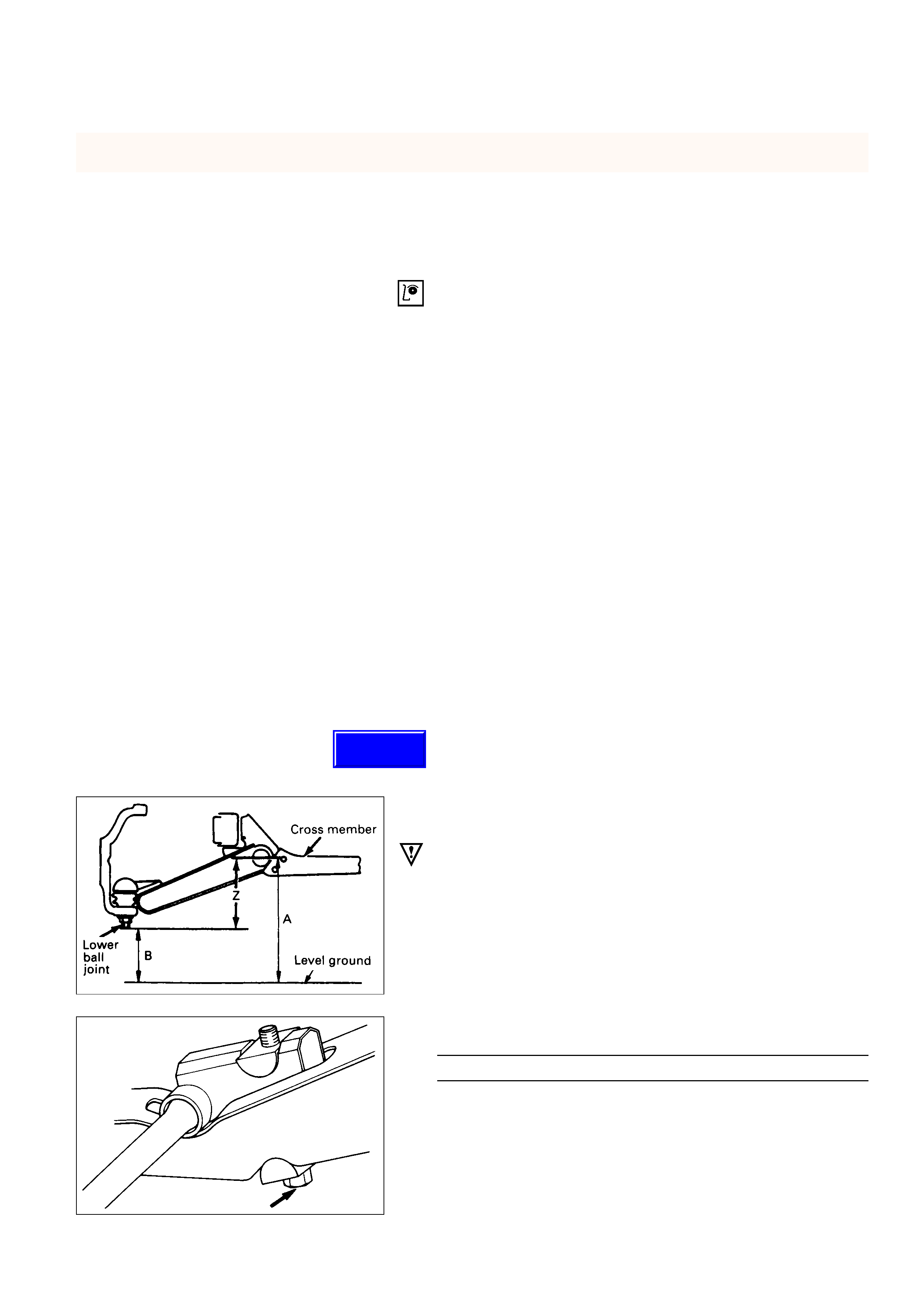
TRIM HEIGHT ADJUSTMENT
Adjust the trim height by means of the adjusting bolt on
the height control arms.
CAUTION:
When adjusting front end alignment, be sure to begin
with trim height as trim height adjustment may change
other adjusted alignments.
1. Check and adjust the tyre inflation pressures.
2. Park the vehicle on a level ground and move the front
of the vehicle up and down several times to settle the
suspension.
3. Make necessary adjustment with the adjusting bolt
on the height control arms.
Trim Height(Z) mm(in)
139 ±5 (5.47 ±0.2)
ON-VEHICLE SERVICE
Techline
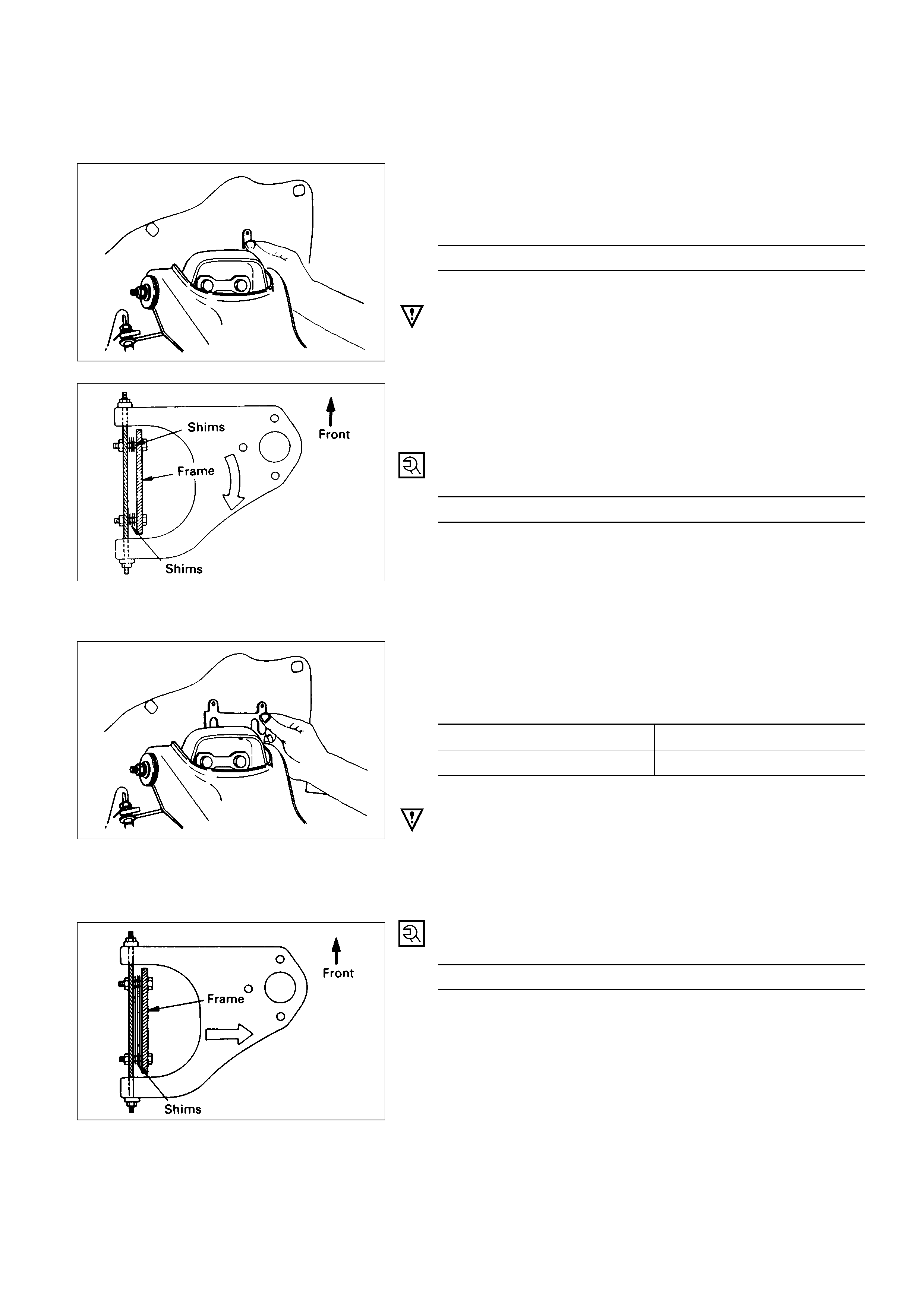
CASTER ADJUSTMENT
The caster angle can be adjusted by means of the caster
shims installed between the chassis frame and fulcrum
pins.
Caster Angle
2°10‘ ±45‘
CAUTION:
Left and right side to be equal within 30’
NOTE:
Difference of the caster shim front/rear thickness shall be
3.2 mm (0.126 in) or less. Overall thickness of caster shim
and camber shim shall be 10.8 mm (0.425 in) or less.
Tighten the fulcrum pin bolt to the specified torque.
Fulcrum Pin Bolt TorqueN·m (kg·m/lb·ft)
152 (15.5 / 112)
CAMBERADJUSTMENT
The camber angle can be adjusted by means of the
camber shims installed in position between the chassis
frame and fulcrum pins.
Wheel Alignment Specification
Camber Angle0°±30‘
King pin inclination12°30‘ ±30‘
CAUTION:
Left and right side to be equal within 30’
NOTE:
Overall thickness of caster shim and camber shim shall
be 10.8 mm (0.425 in) or less.
Tighten the fulcrum pin bolt to the specified torque.
Fulcrum Pin Bolt Torque N·m (kg·m/lb·ft)
152 (15.5 / 112)
Position of shim Camber angleCaster angle
Front sideRear side
When addedWhen removedDecreasesDecreases
When removedWhen addedIncreasesIncreases
Caster shim When removedUnchangedDecreases
When addedUnchangedIncreases
When addedDecreasesUnchanged
Camber shim When removedIncreasesUnchanged
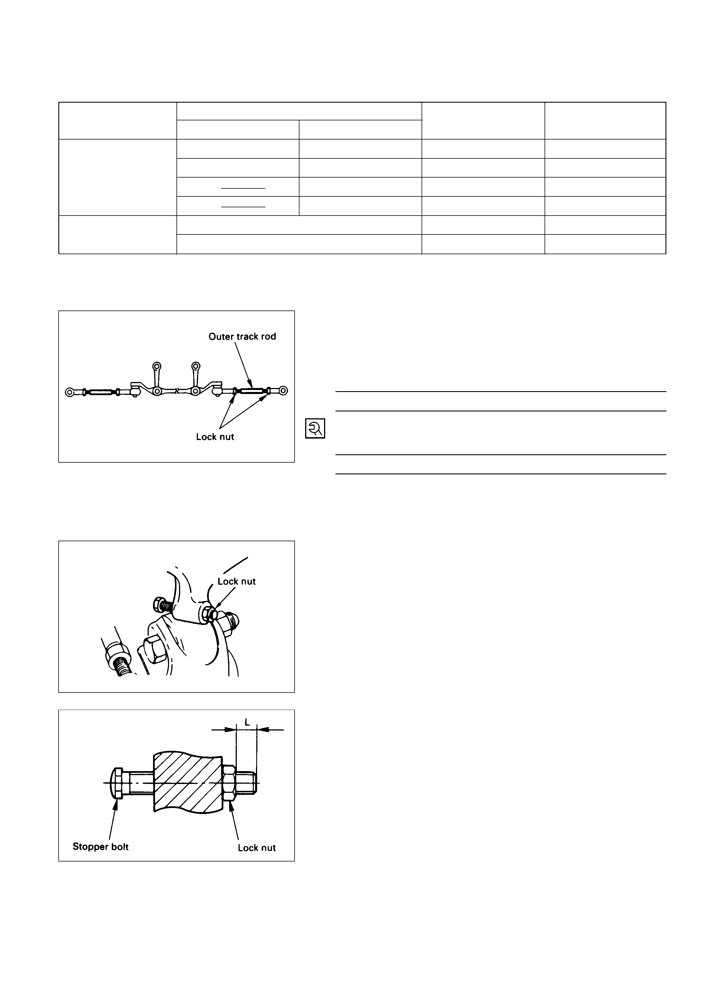
TOE-IN ADJUSTMENT
1.To adjust the toe-in angle, loosen the lock nuts on the
outer track rods and turn the outer track rods. Turn
both rods the same amount, to keep the steering
wheel centered.
Toe-inmm(in)
0 ±2 (0 ±0.08)
2.Tighten the lock nut to the specified torque.
Lock Nut TorqueN·m (kg·m/lb·ft)
118 (12.0 / 87)
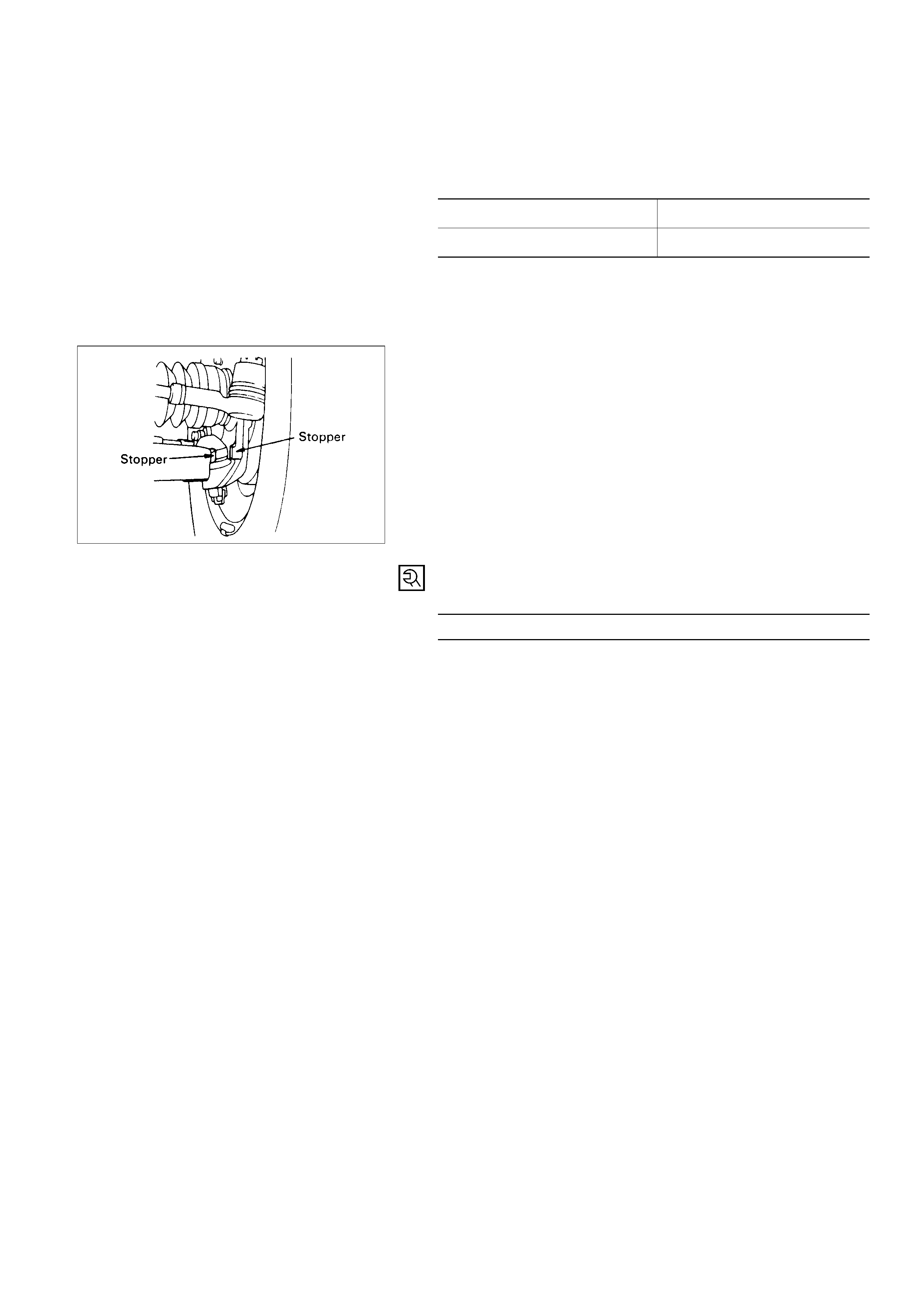
MAXIMUMSTEERINGANGLE
ADJUSTMENT
The maximum steering angle of the front wheels can be
adjusted with the stopper bolts under the frame side
members.
1. Position each front wheel on the turning radius gauge
in a straight-ahead position.
2. Set the parking brake firmly.
3. Adjust the inside wheel angle of each side with the
stopper bolts.
NOTE:
The maximum protruding length (L) of stopper bolt from
the lock nut should be 10 mm (0.4 in) or less.
6. Tighten the lock nut to the specified torque.
Lock Nut Torque N·m (kg·m/lb·ft)
23 (2.3 / 17)
4. Similarly adjust the inside wheel angle of the other
side with stopper bolt.
Maximum Steering Angle
Inside wheel 34° +0°
-2°
Outside wheel 32°
NOTE:
Maximum steering angles should be set after adjusting
front wheel alignment.
5. If the stop between the lower link end and the knuckle
comes ahead of the stopper bolt, adjust the stopper
bolt so that inner stopper bolt touches the drop arm
(relay lever).