
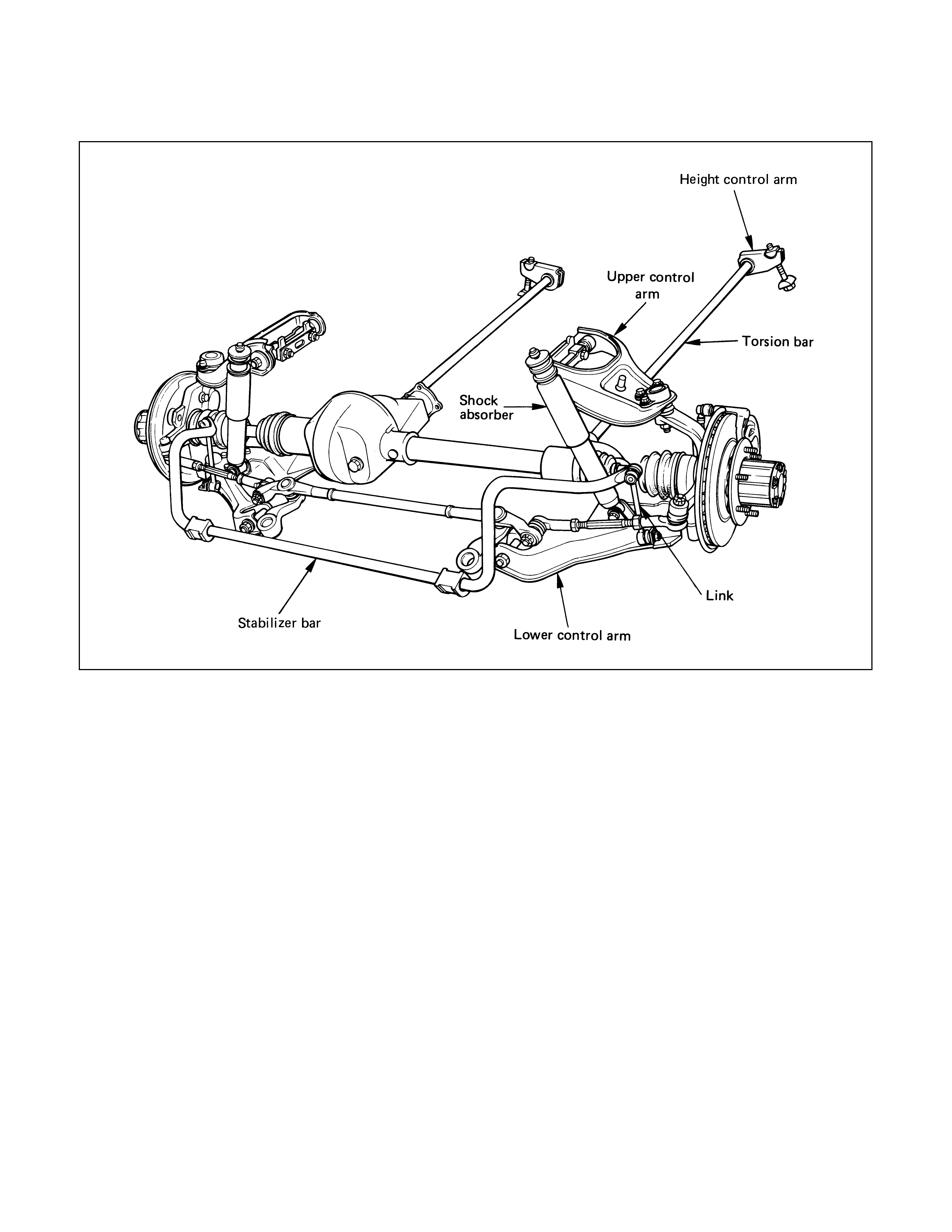
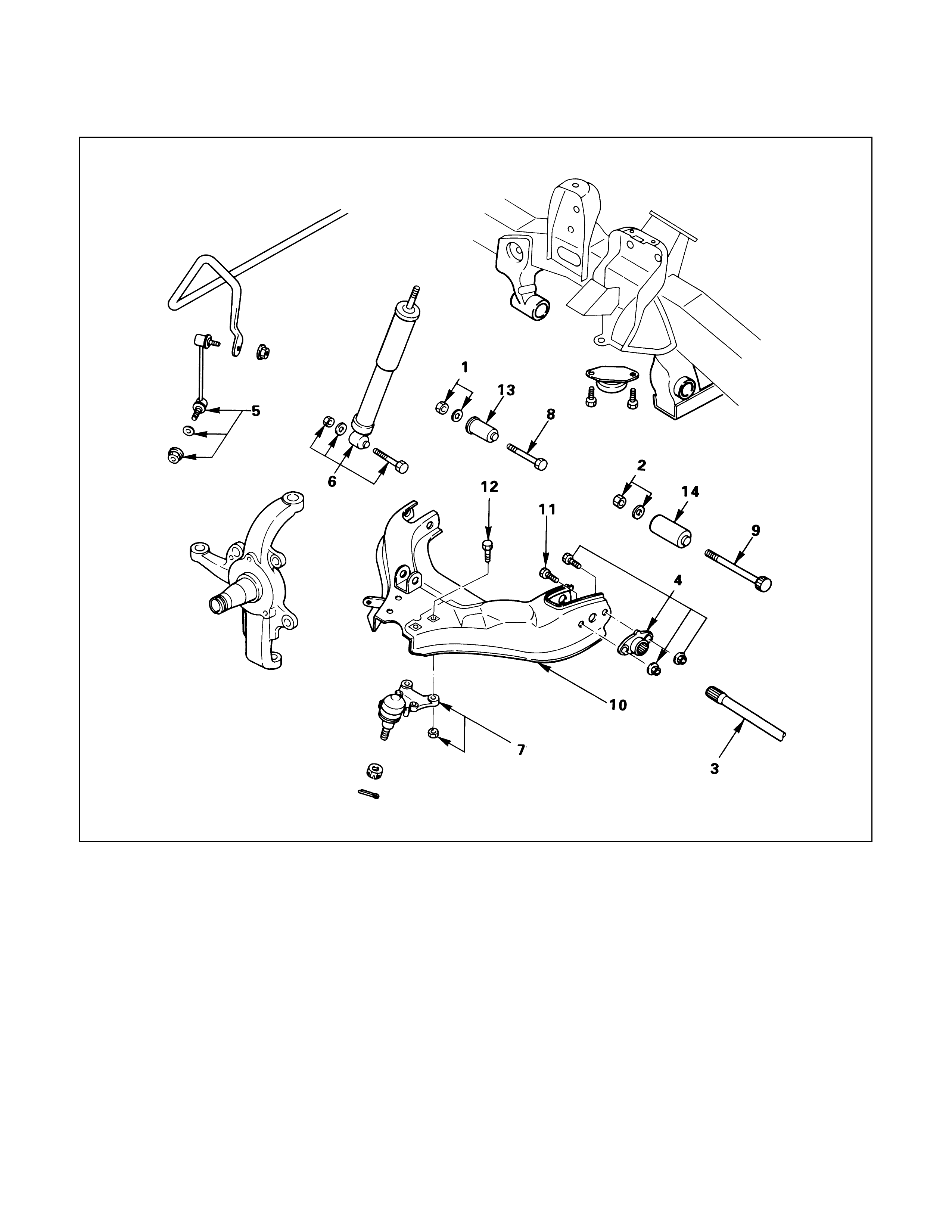
GENERAL DESCRIPTION
The front suspension is designed to allow each
wheel to compensate for changes in the road
surface level without greatly affecting the opposite
wheel. Each wheel is independently connected to
the frame by a steering knuckle, ball joint
assemblies, and upper and lower control arms.
The front wheels are held in proper relationship to
each other by two outer track rods which are
connected to steering arms on the knuckles and to
a center track rod.
All models have a front suspension system
consisting of control arms, stabiliser bar, shock
absorber and a torsion bar. The front end of the
torsion bar is attached to the lower control arm.
The rear of the torsion bar is mounted into a height
control arm at the crossmember. Vehicle trim
height is controlled by adjusting this arm.
Shock absorbers are mounted between the
brackets on the frame and the lower control arms.
The lower portion of each shock absorber is
attached to the lower control arm by a bolt and nut.
The upper portion of each shock absorber extends
through a frame bracket and is secured with two
rubber bushings, three retainers and a nut.
Ball joint assemblies are bolted to the outer end of
the upper and lower control arm and are attached
to the steering knuckle by nuts and cotter pins.
The inner ends of the upper control arm have
pressed in bushings. Bolts passing through the
bushing, attach the control arm to the frame. The
inner ends of the lower control arm are attached to
the frame by bolts passing through the bushings,
which are pressed in the frame.
Side roll of the front suspension is controlled by a
spring steel stabiliser bar. It is mounted in rubber
bushings, which are held to the crossmember by
brackets. The ends of the stabiliser are connected
to the lower control arms by link bolts isolated by
rubber bushings.
ON-VEHICLE SERVICE
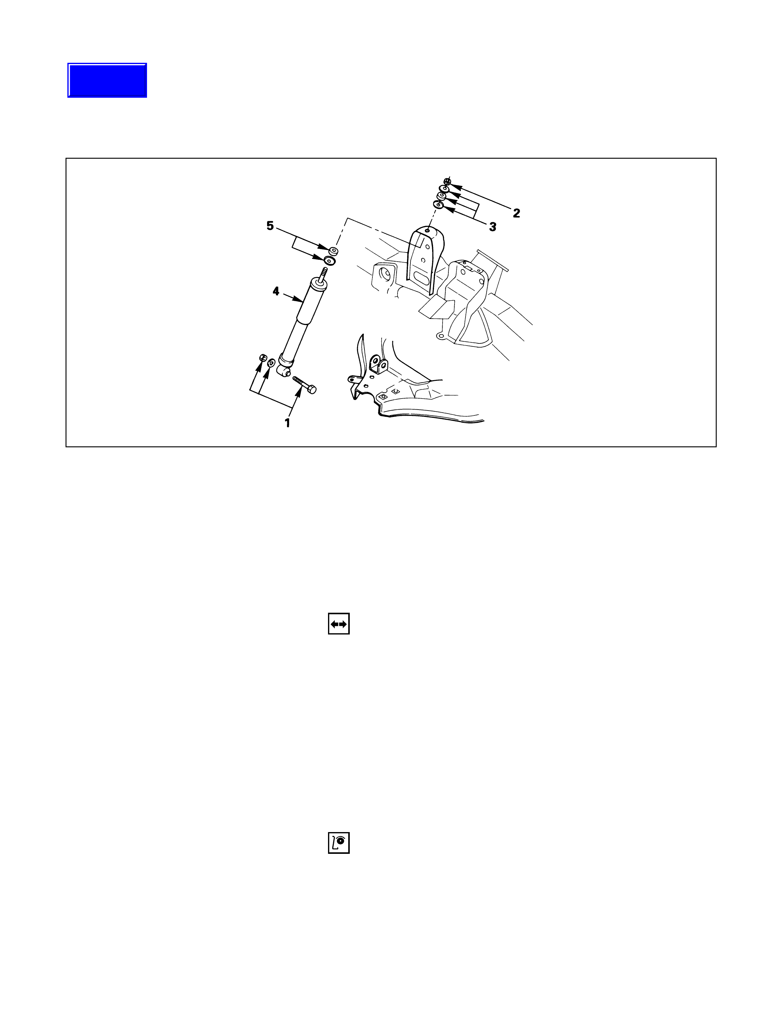
SHOCK ABSORBER
Removal Steps
1. Bolt, nut and washer
2. Nut
3. Rubber bushing and washer
4. Shock absorber
5. Rubber bushing and washer
Installation Steps
5. Rubber bushing and washer
4. Shock absorber
3. Rubber bushing and washer
2. Nut
1. Bolt, nut and washer
REMOVAL
Preparation:
1) Raise the vehicle and support it with suitable safety
stands.
2) Remove wheel and tire assembly. Refer to “Wheels
and Tires” in section 10.
1. Bolt, Nut and Washer
2. Nut
3. Rubber Bushing and Washer
4. Shock Absorber
5. Rubber Bushing and Washer
INSPECTION AND REPAIR
Make necessary correction or parts replacement if wear,
damage, corrosion or any other abnormal condition are
found through inspection.
•Shock absorber
•Rubber bushing
Techline
INSTALLATION
5. Rubber Bushing and Washer
4. Shock Absorber
3. Rubber Bushing and Washer
2. Nut
Shock Absorber Nut Torque N·m (kg·m/lb·ft)
20 (2.0 / 14)
1. Bolt, Nut and Washer
Shock Absorber Nut Torque N·m (kg·m/lb·ft)
82 (8.4 / 61)
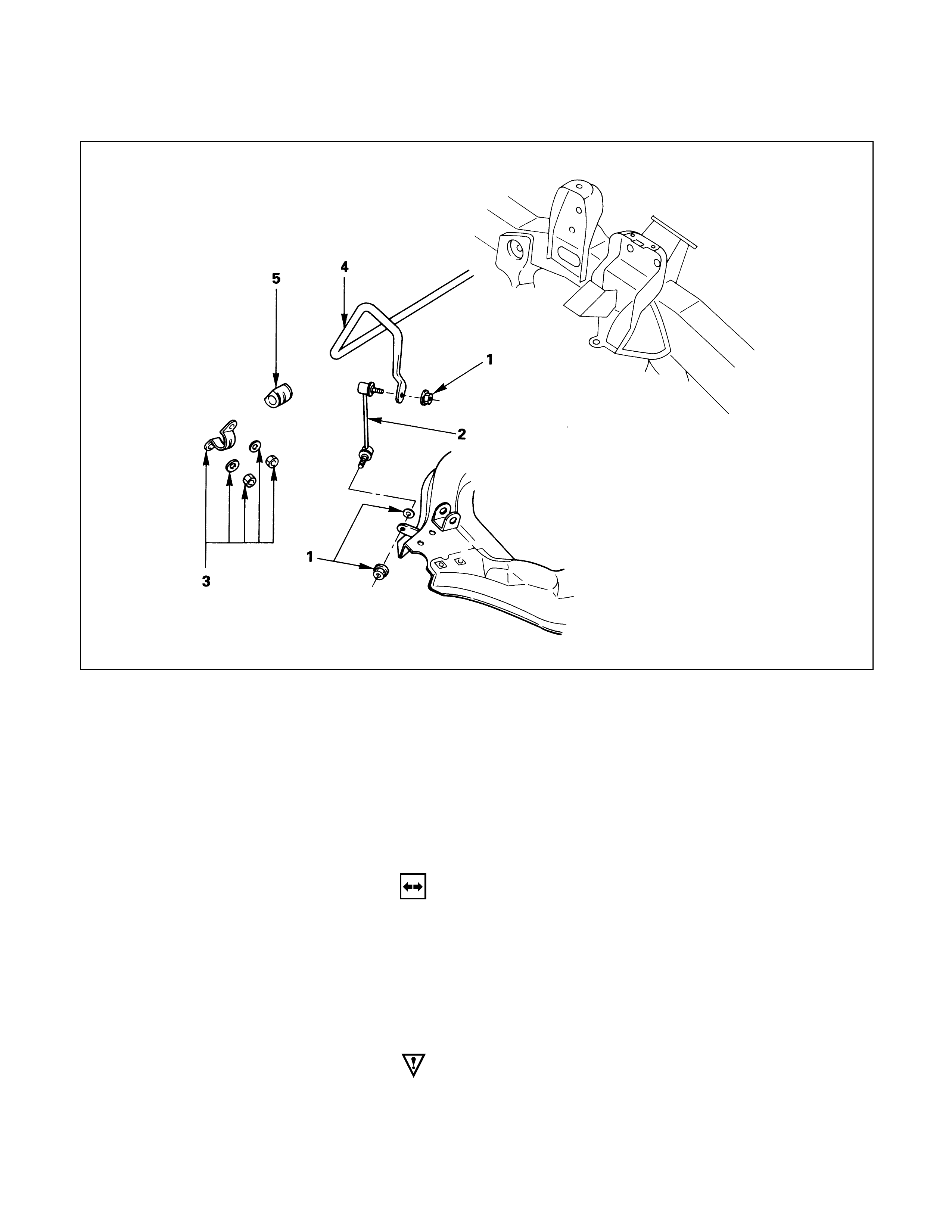
STABILIZER BAR
Removal Steps
1. Nut and washer
2. Link
3. Bracket
4. Stabilizer bar
5. Rubber bushing
Installation Steps
5. Rubber bushing
4. Stabilizer bar
3. Bracket
2. Link
1. Nut and washer
REMOVAL
Preparation:
1) Raise the vehicle and support the frame with suitable
safety stands.
2) Remove the stone guard.
3) Remove wheel and tire assembly. Refer to “Wheels
and Tires” in section 10.
1. Nut and Washer
CAUTION:Be careful not to break the ball joint boot.
2. Link
3. Bracket
4. Stabilizer Bar
5. Rubber Bushing
INSPECTION AND REPAIR
Make necessary correction or parts replacement if wear,
damage, corrosion or any other abnormal condition are
found through inspection.
•Stabilizer bar
•Rubber bushing
•Link ball joint
INSTALLATION
5. Rubber Bushing
4. Stabilizer Bar
3. Bracket
Bracket Nut Torque N·m (kg·m/lb·ft)
22 (2.2 / 16)
2. Link
1. Nut and Washer
Link Nut Torque N·m (kg·m/lb·ft)
50 (5.1 / 37)
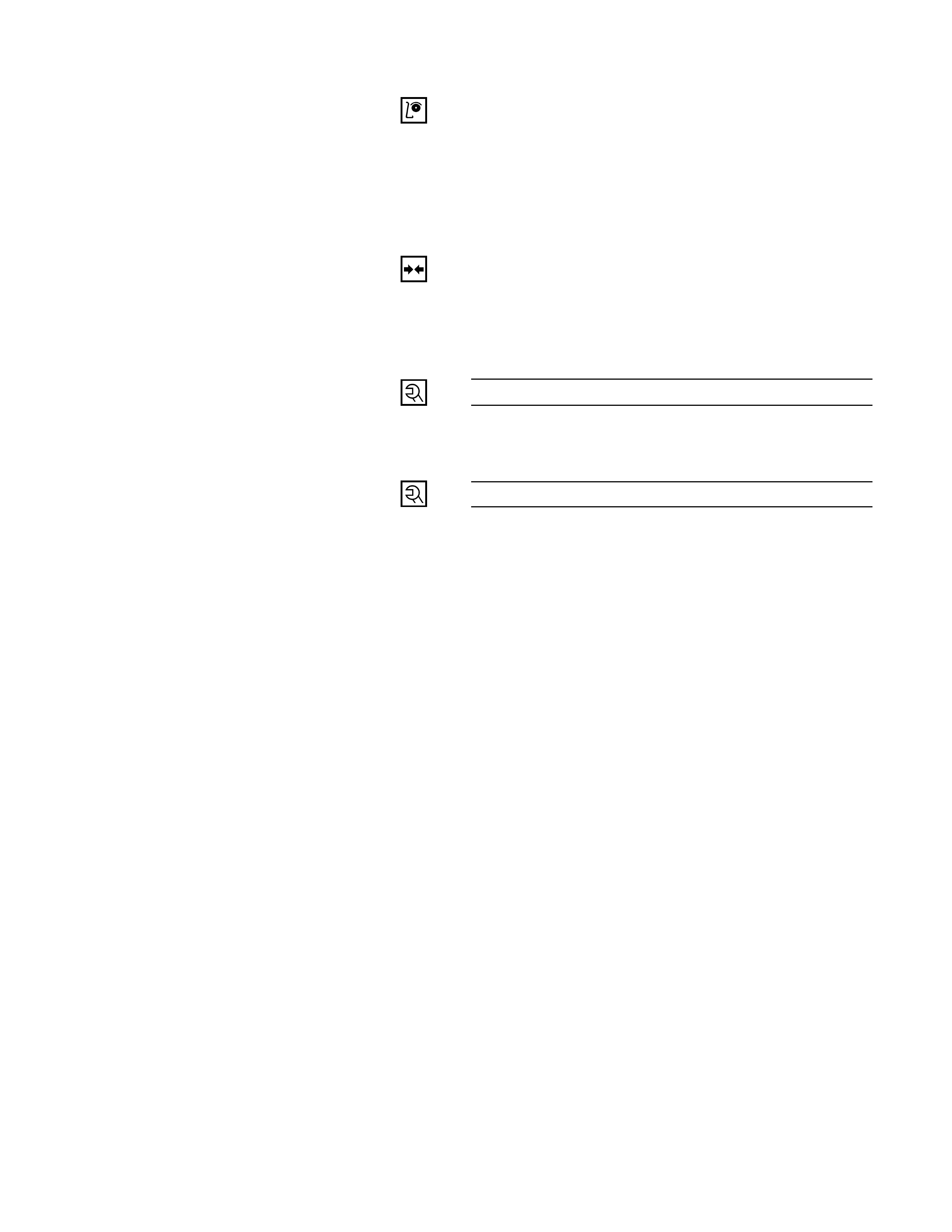
TORSION BAR
Removal Steps
1. Adjust bolt, end piece and seat
2. Height control arm
3. Torsion bar
Installation Steps
3. Torsion bar
2. Height control arm
1. Adjust bolt, end piece and seat
REMOVAL
Preparation:
Raise the vehicle and support the frame with suitable
safety stands.
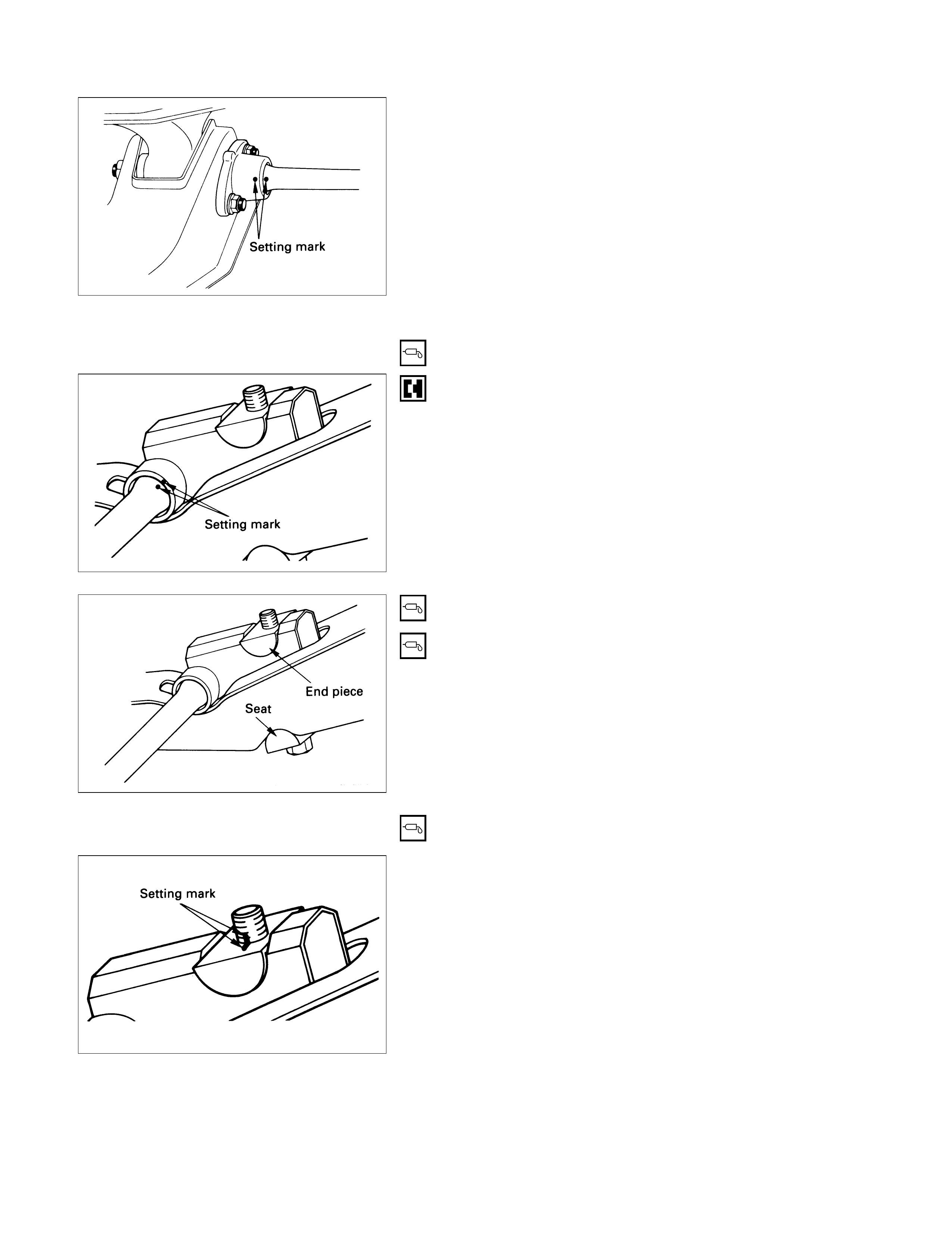
1. Adjust Bolt, End Piece and Seat
Apply the setting marks to the adjust bolt and end
piece.
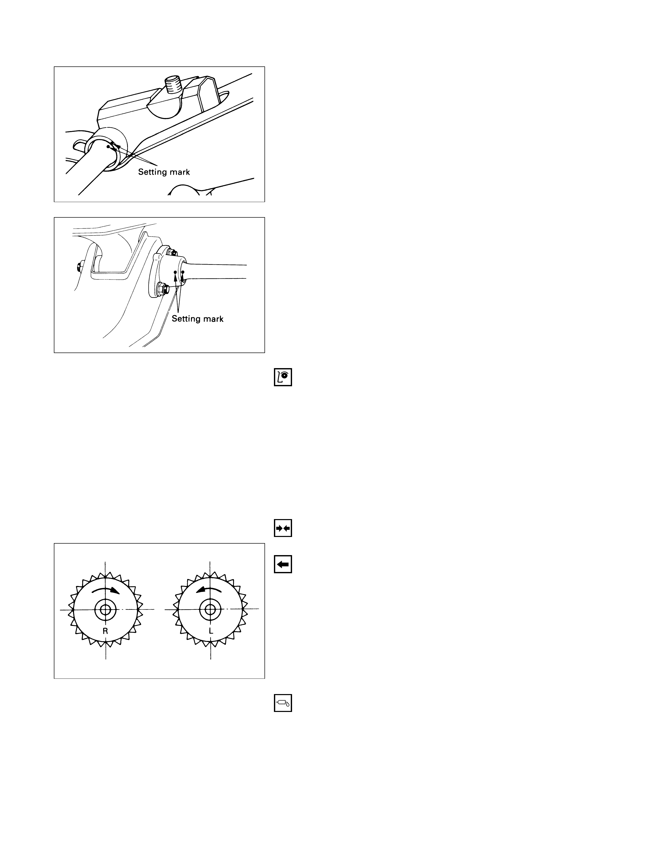
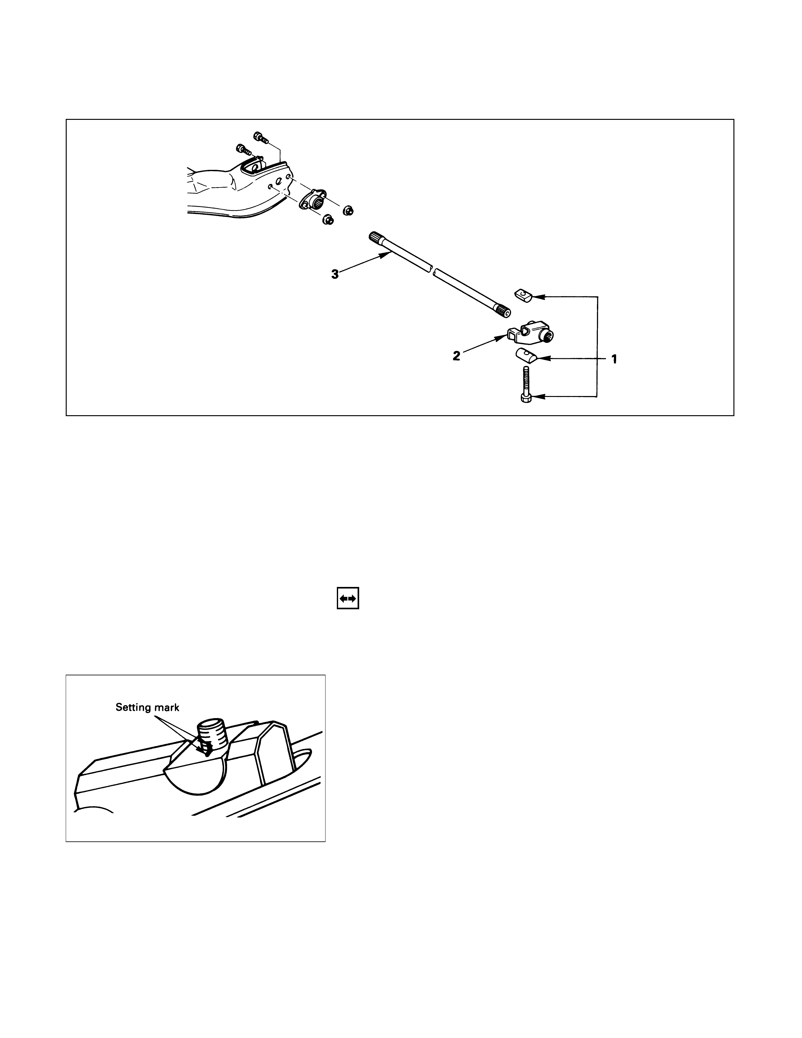
2. Height Control Arm
Apply the setting marks to the height control arm and
torsion bar.
3. Torsion Bar
Apply the setting marks to the torsion bar and lower
control arm.
INSPECTION AND REPAIR
Make necessary correction or parts replacement if wear,
damage, corrosion or any other abnormal condition are
found through inspection.
Check the following parts:
•Torsion bar
•Height control arm
•Adjust bolt
•Rubber seat
INSTALLATION
3. Torsion Bar
Make sure the bars are on their correct respective
sides.
Apply grease to the serrated portions.
Align the setting marks.
2. Height Control Arm
Apply grease to the portion that fits into the bracket.
Align the setting marks.
Apply grease to the bolt portion of the end piece.
Apply grease to the portion of the seat that fits into
the bracket.
Apply grease to the serrated portions.
1. Adjust Bolt and Seat
Turn ther adjust bolt to the setting mark applied
during disassembly.
NOTE:
Adjust the trim height. Refer to “Front End Alignment” in
section 3A.
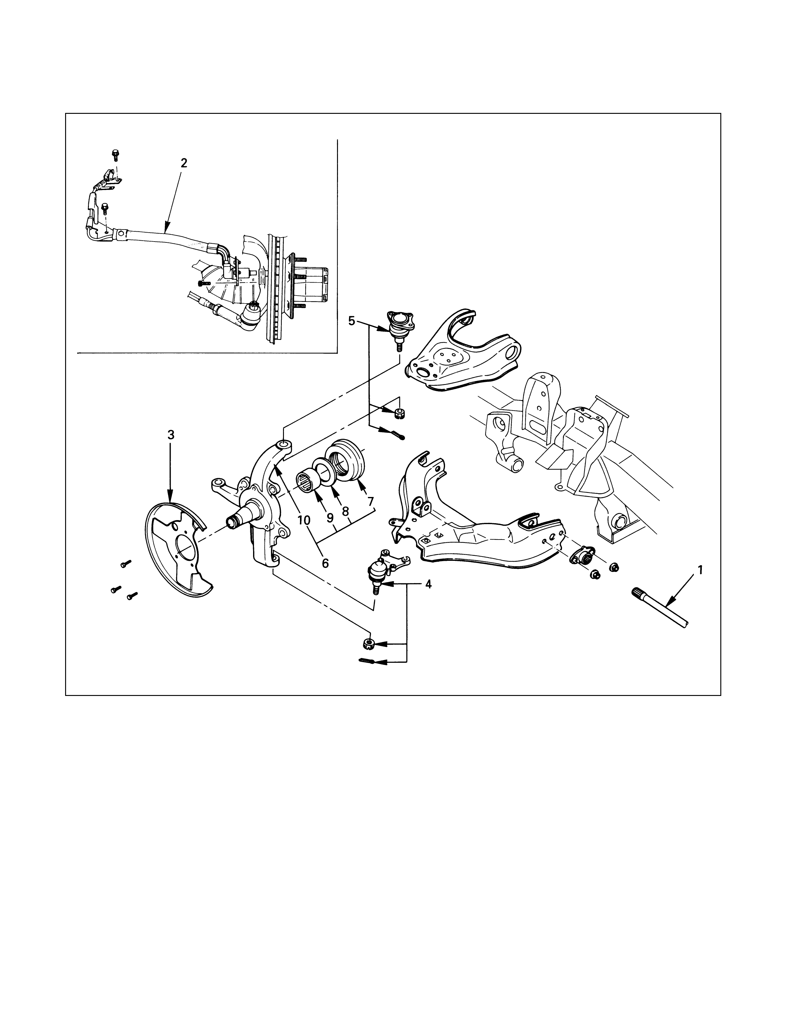
KNUCKLE
Removal Steps
1. Torsion bar
2. Wheel speed sensor
(if equipped with ABS)
3. Back plate
4. Lower ball joint
5. Upper ball joint
6. Knuckle assembly
7. Oil seal
8. Thrust washer
9. Needle bearing
10. Knuckle
Installation Steps
10. Knuckle
9. Needle bearing
8. Thrust washer
7. Oil seal
6. Knuckle assembly
5. Upper ball joint
4. Lower ball joint
3. Back plate
2. Wheel speed sensor
(if equipped with ABS)
1. Torsion bar
REMOVAL
Preparation:
1) Raise the vehicle and support the frame with suitable
safety stands.
2) Remove wheel and tire assembly. Refer to “Wheels
and Tires” in section 10.
3) Remove the brake caliper. Refer to “Brakes” in section
5.
4) Remove the hub assembly. Refer to “Hub and Disk” in
section 4D.
5) Remove outer track rod from the knuckle. Refer to
“Steering Linkage” in section 9B.
1. Torsion Bar
Loosen torsion bar by height control arm adjust bolt.
Refer to “Torsion bar” in this section.
2. Wheel speed sensor (if equipped with ABS)
3. Back Plate
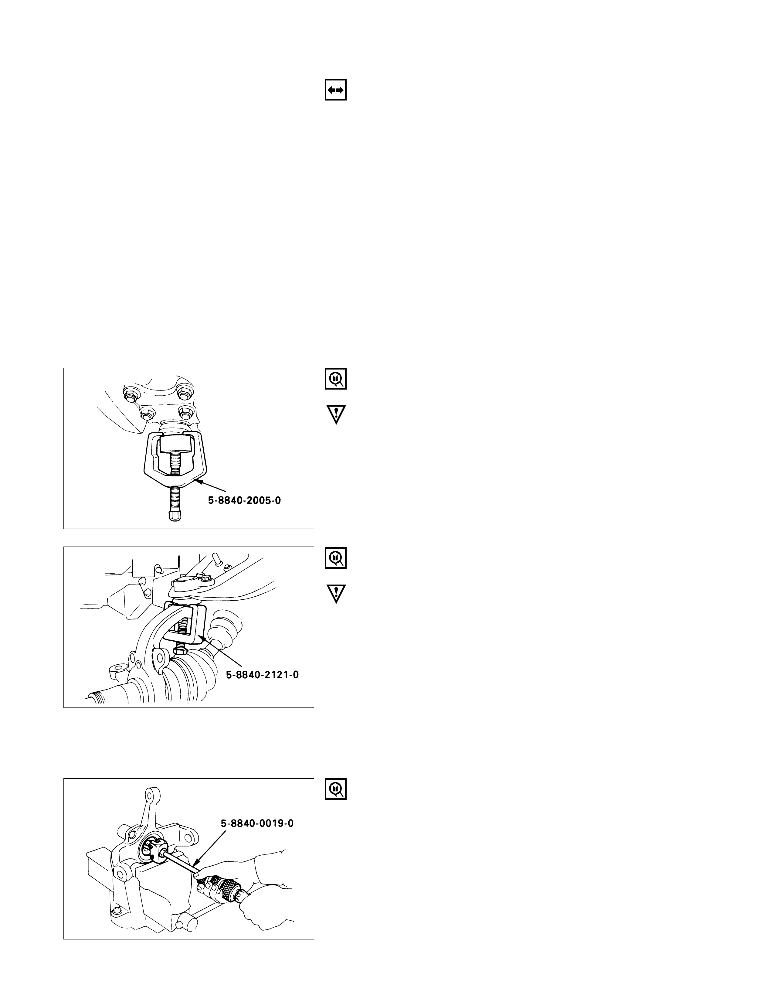
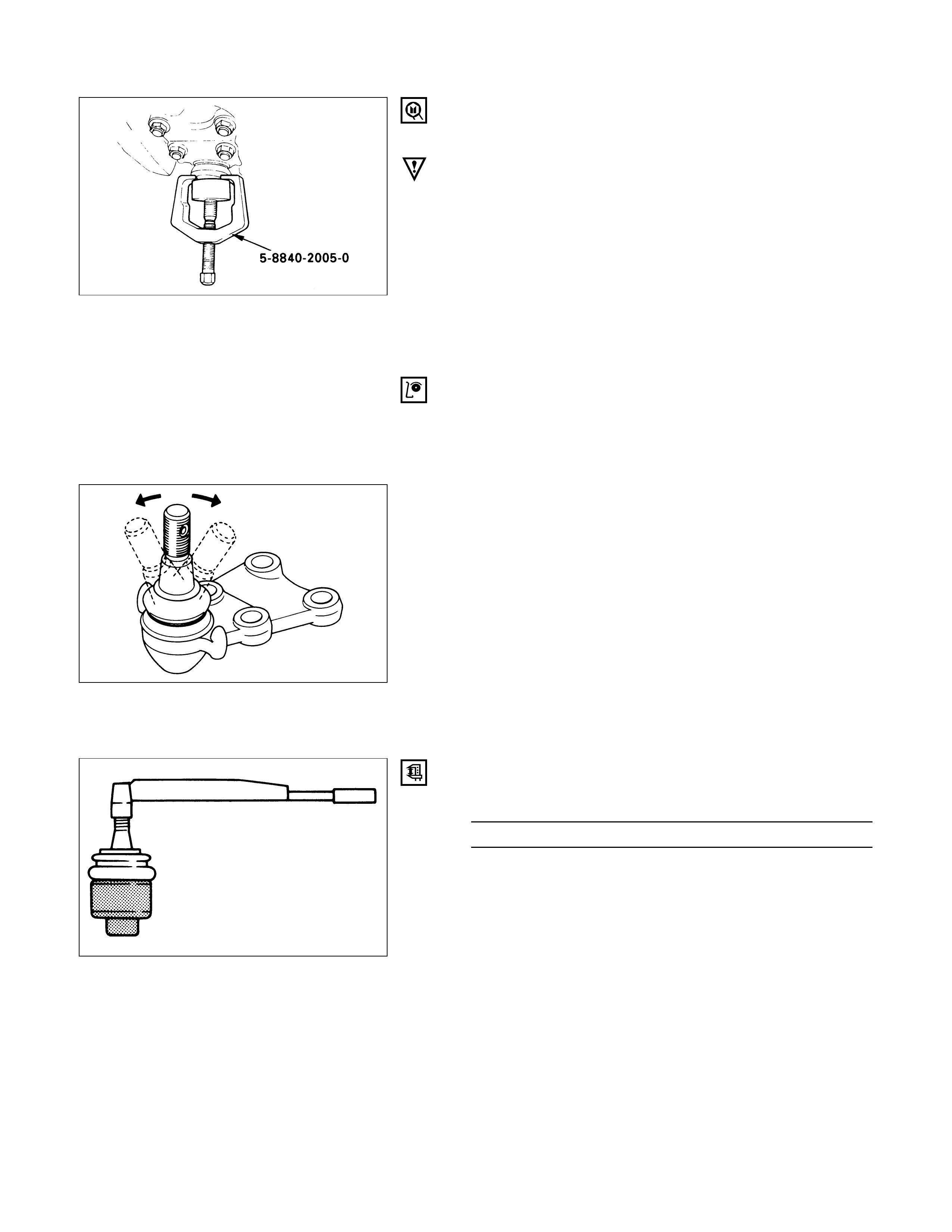
4. Lower Ball Joint
Remover: 5-8840-2005-0 (J-29107)
CAUTION:
Be careful not to break the ball joint boot.
5. Upper Ball Joint
Remover: 5-8840-2121-0 (J-36831)
CAUTION:
Be careful not to break the ball joint boot.
6. Knuckle Assembly
7. Oil Seal
8. Washer
9. Needle Bearing
Remover: 5-8840-0019-0 (J-23907)
10. Knuckle
INSPECTION AND REPAIR
Make necessary correction or parts replacement if wear,
damage, corrosion or any other abnormal condition are
found through inspection.
Check the following parts:
•Knuckle
•Needle bearing
•Thrust washer
INSTALLATION
10. Knuckle
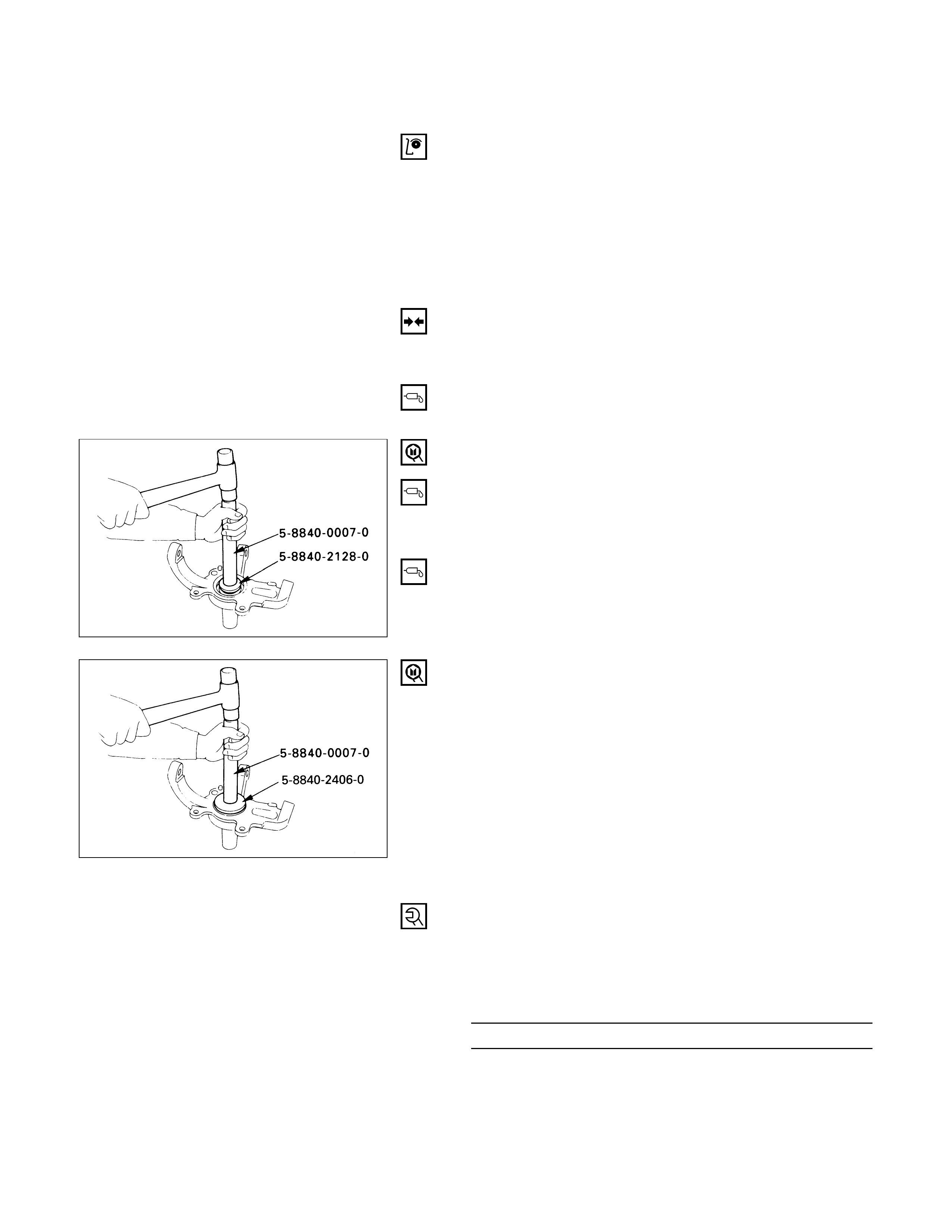
9. Needle Bearing
Before installation, apply appropriate amount of
multipurpose type grease to the new bearing (Approx.
5 g).
Installer: 5-8840-2128-0 (J-36838) and
5-8840-0007-0 (J-8092)
8. Washer
Apply multipurpose type grease to the thrust washer,
and install it with chamfered side facing knuckle.
7. Oil Seal
Use a new oil seal, and apply multipurpose type
grease to the area surrounded by the lip (approx. 2 g).
After fitting the oil seal to the installer, drive it to the
knuckle using a hammer or bench press until the tool
front face contacts with the thrust washer.
Installer: 5-8840-2406-0 (J-41468)and
5-8840-0007-0 (J-8092)
6. Knuckle Assembly
5. Upper Ball Joint
Tighten the nut to the specified torque, with just
enough additional torque to align cotter pin holes.
Install new cotter pin.
Upper Ball Joint Nut Torque N·m (kg·m/lb·ft)
98 (10.0 / 72)
4. Lower Ball Joint
Tighten the nut to the specified torque, with just
enough additional torque to align cotter pin holes.
Install new cotter pin.
Lower Ball Joint Nut Torque N·m (kg·m/lb·ft)
147 (15.0 / 108)
3. Back Plate
2. Wheel Speed Sensor (if equipped with ABS)
Tighten the bolt to the specified torque.
Wheel Speed Sensor Bolt Torque N·m (kg·m/lb·in)
8 (0.8 / 69)
1. Torsion Bar
Refer to “Torsion Bar” in this section.
NOTE:
Adjust the trim height. Refer to “Front End
Alignment” in section 3A.
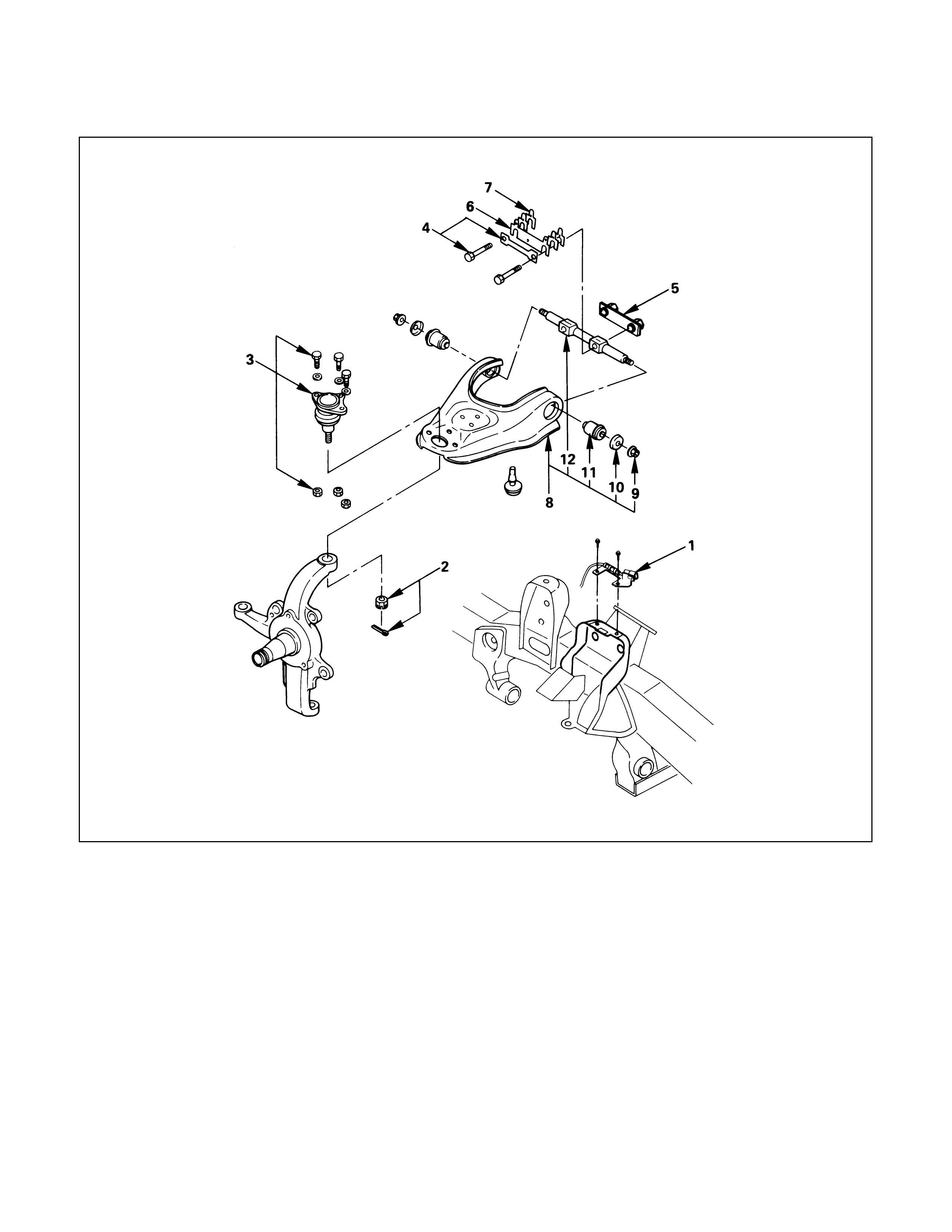
UPPER CONTROL ARM
Removal Steps
1. Speed sensor cable (if equipped with
ABS)
2. Nut and cotter pin
3. Upper ball joint
4. Bolt and plate
5. Nut assembly
6. Camber shims
7. Caster shims
8. Upper control arm assembly
9. Nut
10. Plate
11. Bushing
12. Fulcrum pin
Installation Steps
12. Fulcrum pin
11. Bushing
10. Plate
9. Nut
8. Upper control arm assembly
7. Caster shims
6. Camber shims
5. Nut assembly
4. Bolt and plate
3. Upper ball joint
2. Nut and cotter pin
1. Speed sensor cable (if equipped with
ABS)
REMOVAL
Preparation:
1) Raise the vehicle and support the frame with suitable
safety stands.
2) Remove wheel and tire assembly. Refer to “Wheels
and Tires” in section 10.
3) Remove the brake caliper and disconnect flexible hose.
Refer to “Brakes” in section 5.
4) Support lower control arm with a jack.
1. Speed Sensor Cable (if equipped with ABS)
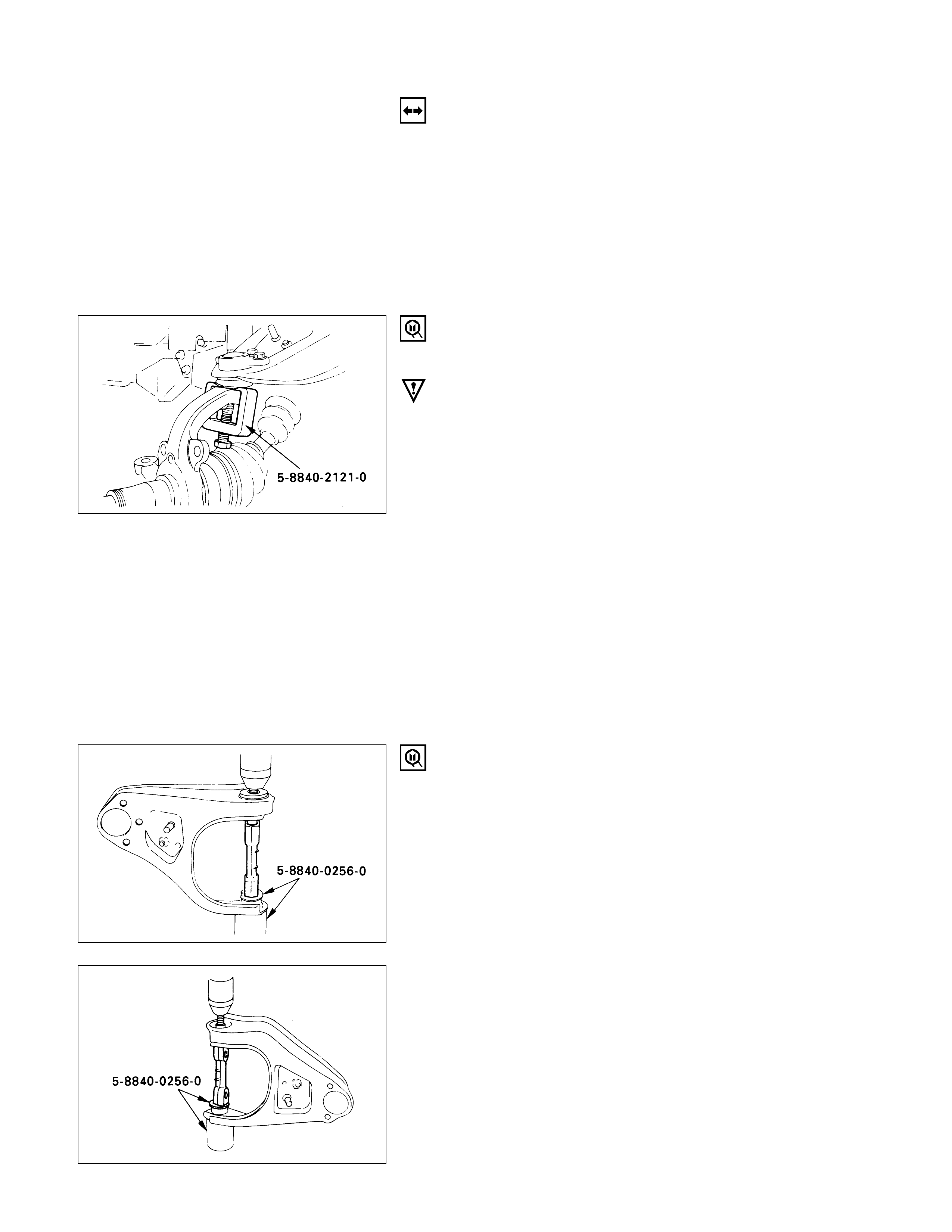
2. Nut and Cotter Pin
Remove the upper ball joint from the knuckle.
Remover: 5-8840-2121-0 (J-36831)
CAUTION:
Be careful not to break the ball joint boot.
3. Upper Ball Joint
4. Bolt and Plate
5. Nut Assembly
6. Camber Shims
Note the positions and number of shims.
7. Caster Shims
Note the positions and number of shims.
8. Upper Control Arm Assembly
9. Nut
10. Plate
11. Bushing
Remover: 5-8840-0256-0 (J-29755)
12. Fulcrum Pin
INSPECTION AND REPAIR
Make necessary parts replacement if wear, damage,
corrosion or any other abnormal conditions are found
through inspection.
Check the following parts:
•Upper control arm
•Bushing
•Fulcrum pin
INSTALLATION
12. Fulcrum Pin
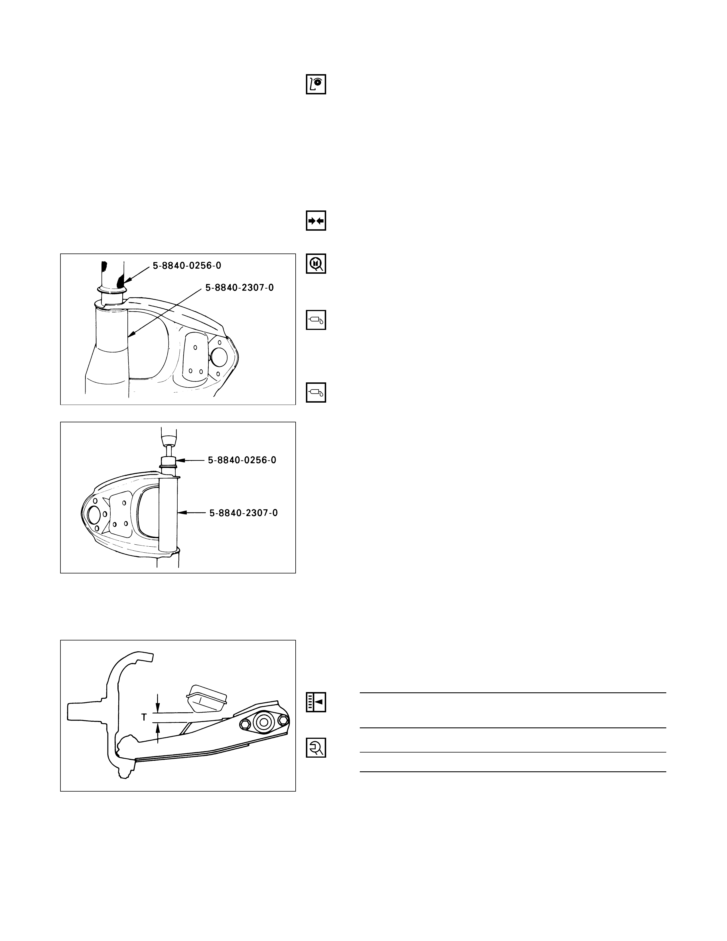
11. Bushing
Installer: 5-8840-0256-0 (J-29755) and
5-8840-2307-0 (J-39376)
10. Plate
9. Nut
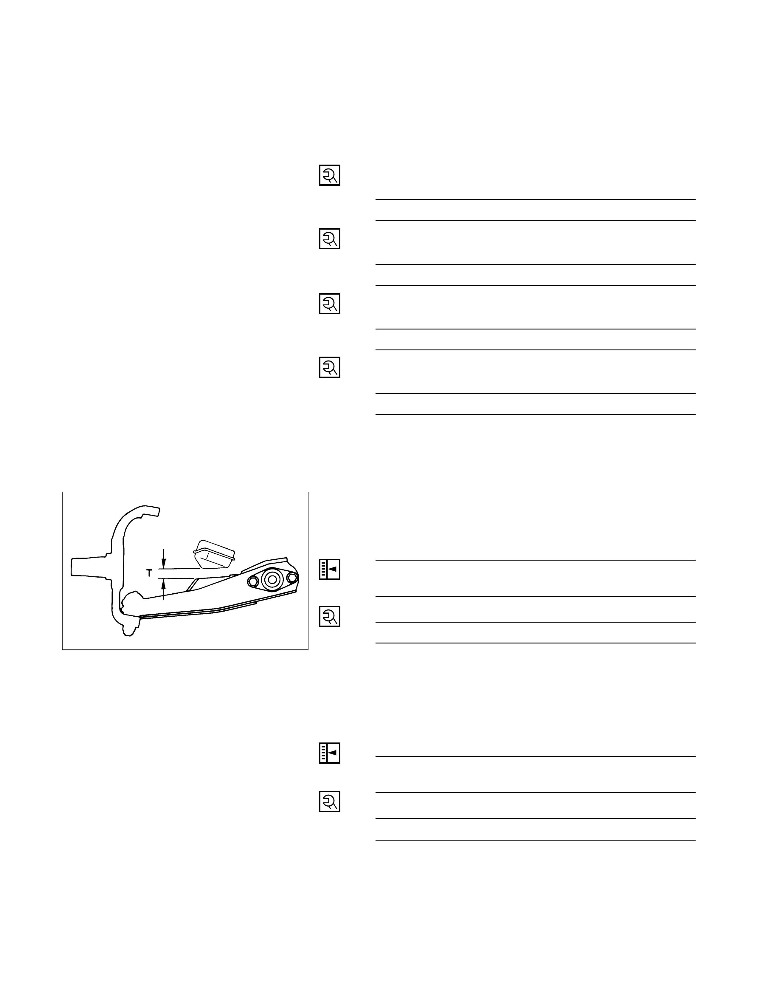
Tighten fulcrum pin nut finger-tight.
NOTE:
Torque fulcrum pin nut after adjusting buffer clearance.
Buffer Clearance (T) mm (in)
23 (0.91) Wide Tread
24 (0.94) Narrow Tread
Fulcrum Pin Nut Torque N·m (kg·m/lb·ft)
108 (11.0 / 80)
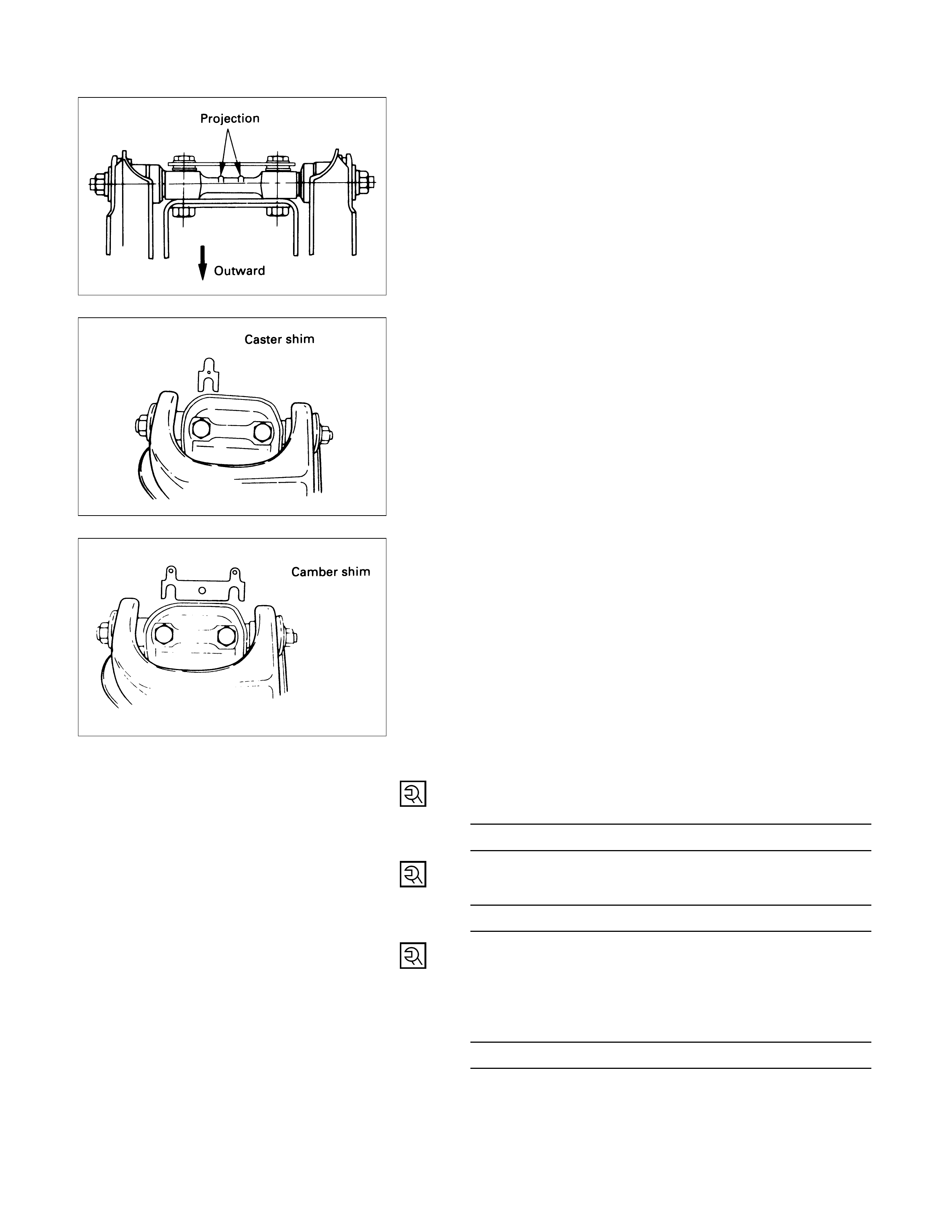
8. Upper Control Arm Assembly
Install upper control arm assembly with the fulcrum
pin projections turned inward.
7. Caster Shims
Install the caster shims between the chassis frame and
fulcrum pin.
6. Camber Shims
Install the camber shims between the chassis frame
and fulcrum pin.
5. Nut Assembly
4. Bolt and Plate
Fulcrum Pin Bolt Torque N·m (kg·m/lb·ft)
152 (15.2 / 112)
3. Upper Ball Joint
Upper Ball Joint Nut Torque N·m (kg·m/lb·ft)
57 (5.8 / 42)
2. Nut and Cotter Pin
Tighten the nut to the specified torque, with just
enough additional torque to align cotter pin holes.
Install new cotter pin.
Upper Ball Joint Nut Torque N·m (kg·m/lb·ft)
98 (10.0 / 72)
1. Speed Sensor Cable (if equipped with ABS)
LOWER CONTROL ARM
Removal Steps
1. Nut and washer, front
2. Nut and washer, rear
3. Torsion bar
4. Torsion bar arm
5. Stabilizer link
6. Shock absorber
7. Lower ball joint
8. Bolt, front
9. Bolt, rear
10. Lower control arm
11. Bolt, torsion bar arm
12. Bolt, lower ball joint
13. Bushing, front
14. Bushing, rear
Installation Steps
14. Bushing, rear
13. Bushing, front
12. Bolt, lower ball joint
11. Bolt, torsion bar arm
10. Lower control arm
9. Bolt, rear
8. Bolt, front
7. Lower ball joint
6. Shock absorber
5. Stabilizer link
4. Torsion bar arm
3. Torsion bar
2. Nut and washer, rear
1. Nut and washer, front
REMOVAL
Preparation:
1) Raise the vehicle and support the frame with suitable
safety stands.
2) Remove wheel and tire assembly. Refer to “Wheels
and Tires” in section 10.
3) Remove the outer track rod from the knuckle. Refer to
“Steering Linkage” in section 9B.
4) Remove the retaining ring from the front axle driving
shaft to release the shaft from hub. Refer to “Front
Axle” in section 4B.
5) Support lower control arm with a jack.
1. Nut and Washer, Front
2. Nut and Washer, Rear
3. Torsion Bar
Refer to “Torsion Bar” in this section.
4. Torsion Bar Arm Bracket
5. Stabilizer Link
Disconnect the link at the lower control arm.
6. Shock Absorber
Remove the shock absorber lower end from the lower
control arm.
7. Lower Ball Joint
Remove the lower ball joint from the lower control
arm.
8. Bolt, Front
9. Bolt, Rear
10. Lower Control Arm
11. Bolt, Torsion Bar Arm
12. Bolt, Lower Ball Joint
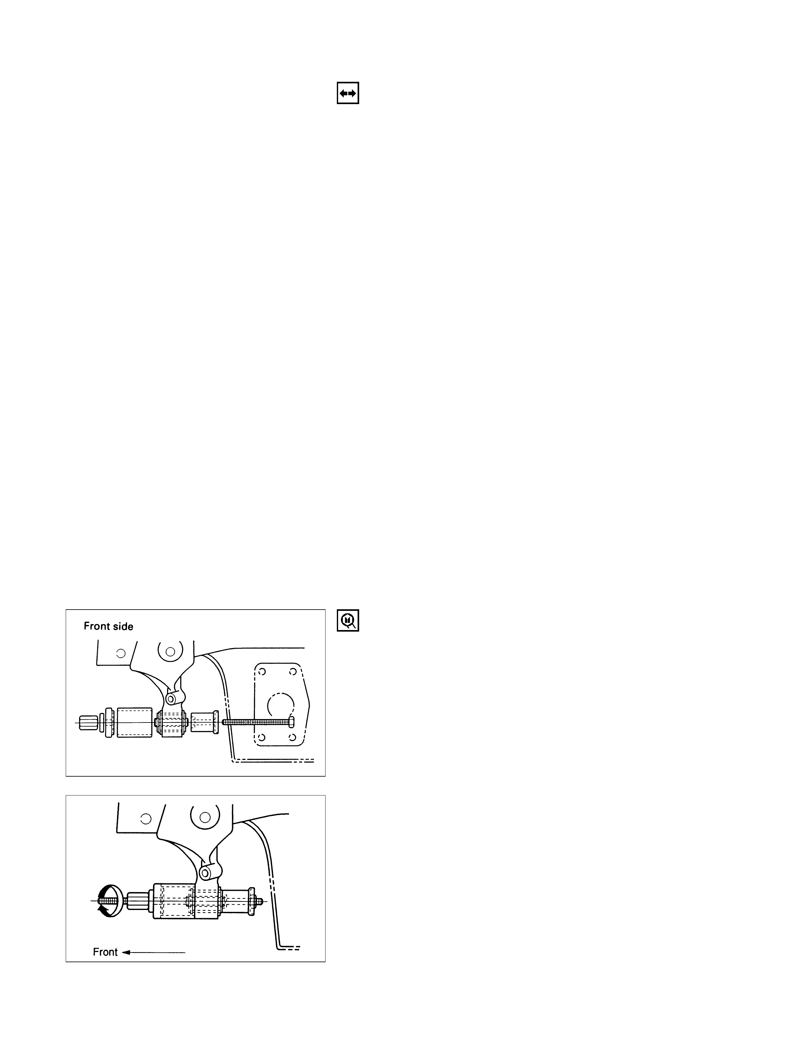
13. Bushing, Front
Remover: 5-8840-2123-0 (J-36833)
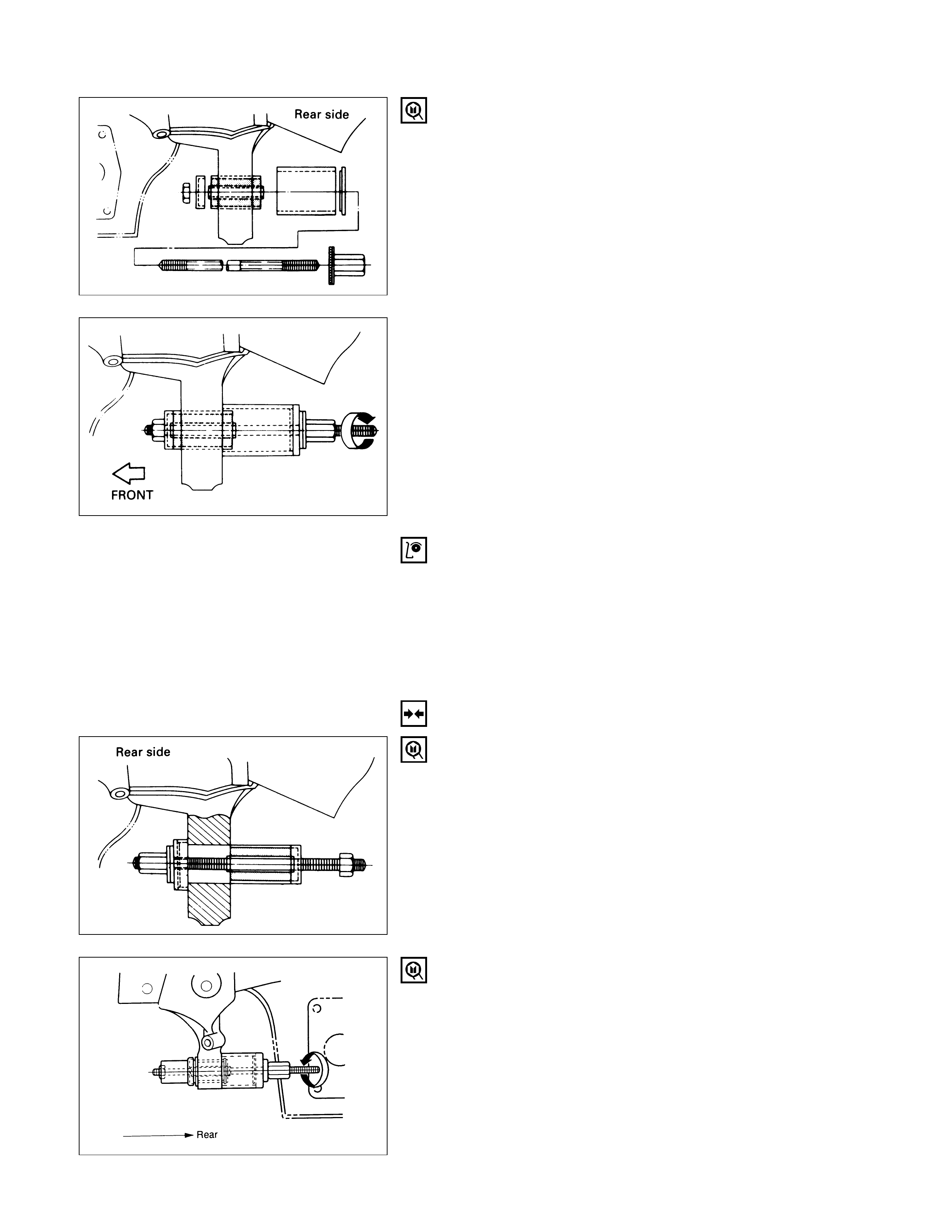
14. Bushing, Rear
Remover: 5-8840-2124-0 (J-36834)
INSPECTION AND REPAIR
Make necessary correction or parts replacement if wear,
damage, corrosion or any other abnormal condition are
found through inspection.
Check the following parts:
•Lower control arm
•Bushing
INSTALLATION
14. Bushing, Rear
Installer: 5-8840-2124-0 (J-36834)
13. Bushing, Front
Installer: 5-8840-2123-0 (J-36833)
12. Bolt, Lower Ball Joint
11. Bolt, Torsion Bar Arm
10. Lower Control Arm
9. Bolt, Rear
8. Bolt, Front
7. Lower Ball Joint
Lower Ball Joint Nut Torque N·m (kg·m/lb·ft)
103 (10.5 / 76)
6. Shock Absorber
Shock Absorber Nut Torque N·m (kg·m/lb·ft)
82 (8.4 / 61)
5. Stabilizer Link
Link Nut Torque N·m (kg·m/lb·ft)
50 (5.1 / 37)
4. Torsion Bar Arm Bracket
Torsion Bar Arm Bracket Nut Torque N·m (kg·m/lb·ft)
116 (11.8 / 85)
3. Torsion Bar
Refer to “Torsion Bar” in this section.
2. Nut and Washer, Rear
Tighten lower link nut finger-tight.
NOTE:
Torque lower control arm nut after adjusting buffer
clearance.
Buffer Clearance (T) mm (in)
23 (0.91) Wide Tread
24 (0.94) Narrow Tread
Lower Arm Rear Nut Torque N·m (kg·m/lb·ft)
196 (20.0 / 145)
1. Nut and Washer, Front
Tighten lower link nut finger-tight.
NOTE:
Torque lower control arm nut after adjusting buffer
clearance.
Buffer Clearance (T) mm (in)
23 (0.91) Wide Tread
24 (0.94) Narrow Tread
Lower Arm Front Nut Torque N·m (kg·m/lb·ft)
157 (16.0 / 116)
NOTE:
Adjust the trim height. Refer to “Front End Alignment” in
section 3A.
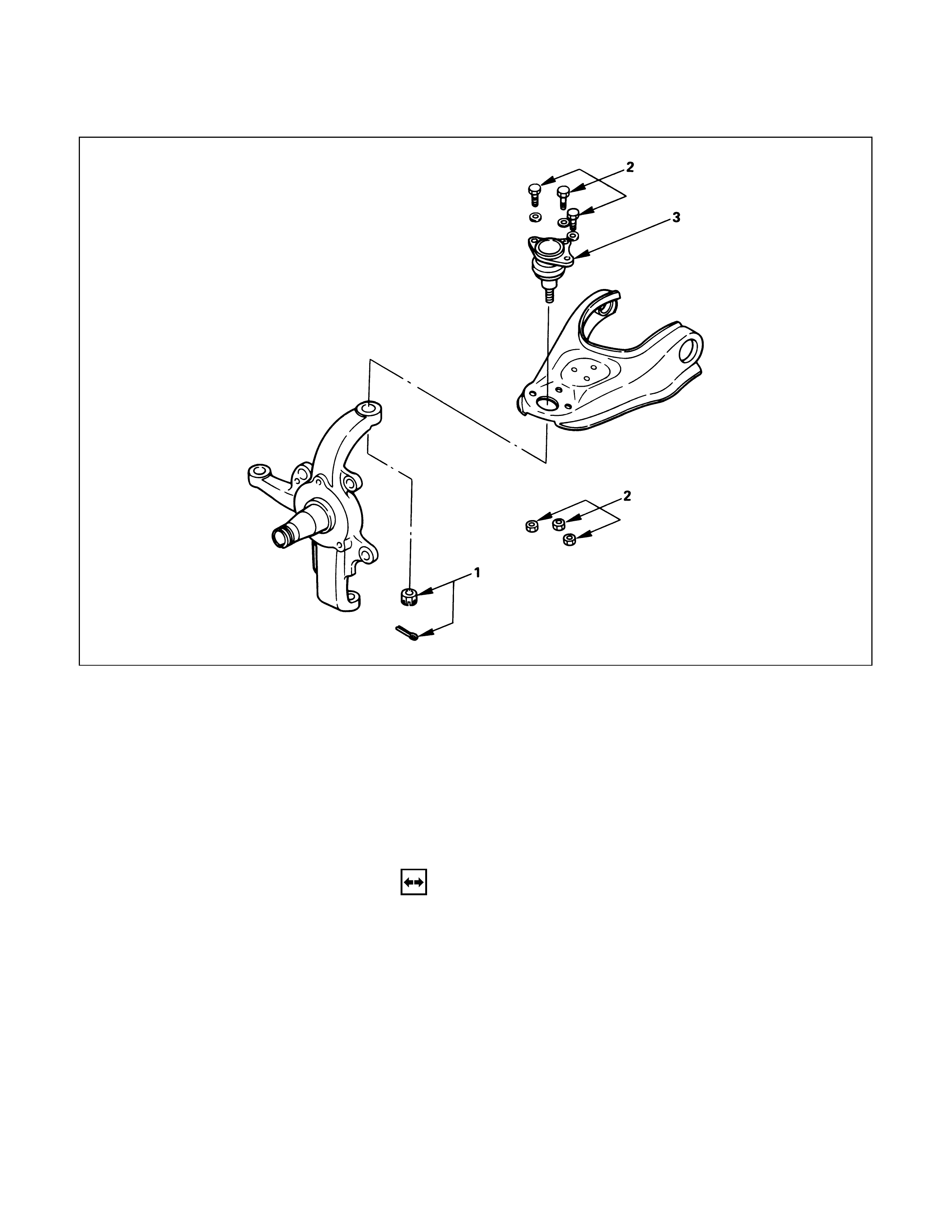
UPPER BALL JOINT
Removal Steps
1. Nut and cotter pin
2. Bolt, nut and washer
3. Upper ball joint
Installation Steps
3. Upper ball joint
2. Bolt, nut and washer
1. Nut and cotter pin
REMOVAL
Preparation:
1) Raise the vehicle and support the frame with suitable
safety stands.
2) Remove the speed sensor from the knuckle (If
equipped with ABS).
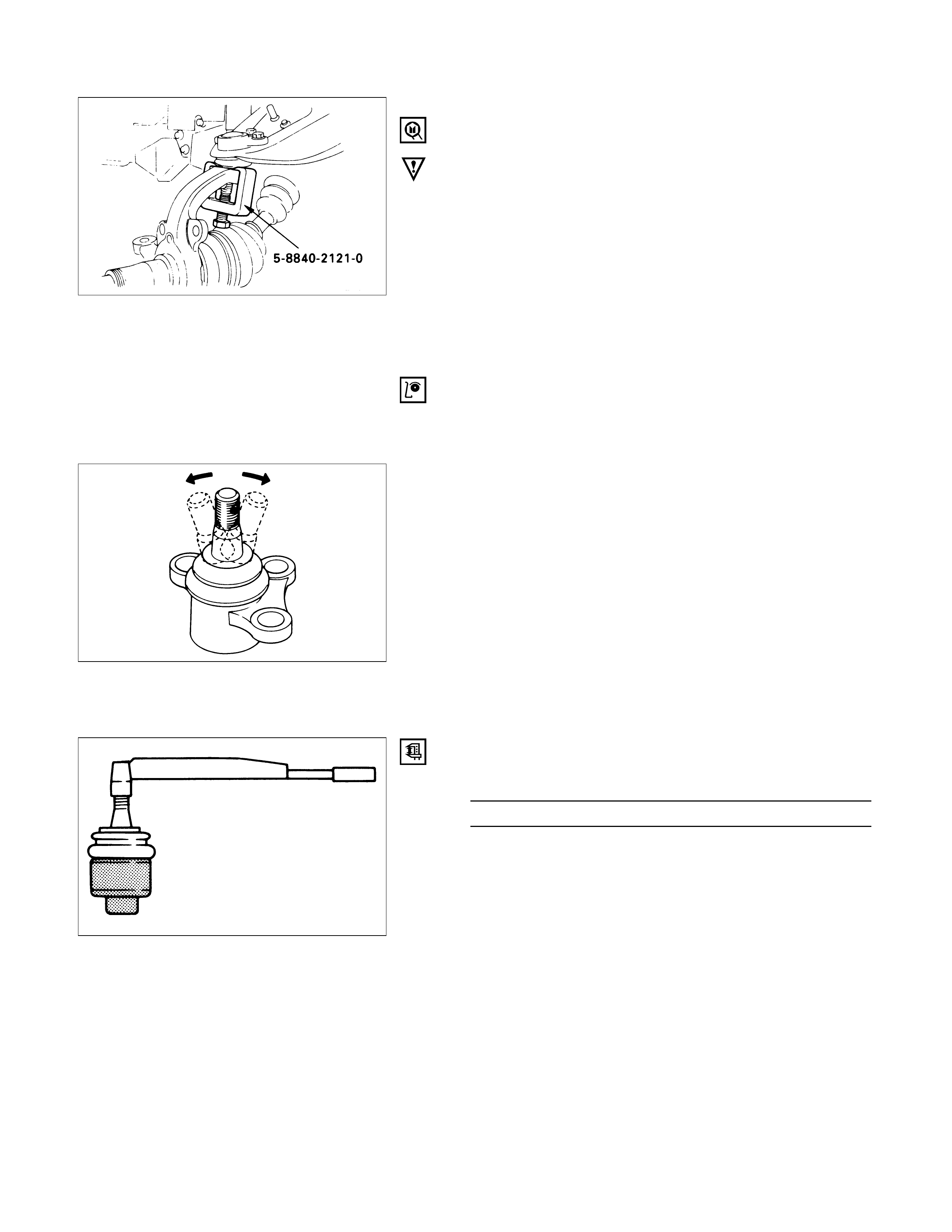
1. Nut and Cotter Pin
Remove the upper ball joint from the knuckle.
Remover: 5-8840-2121-0 (J-36831)
CAUTION:
Be careful not t o break the ball joint boot.
2. Bolt, Nut and Washer
3. Upper Ball Joint
INSPECTION AND REPAIR
Make necessary parts replacement if wear, damage,
corrosion or any other abnormal conditions are found
through inspection.
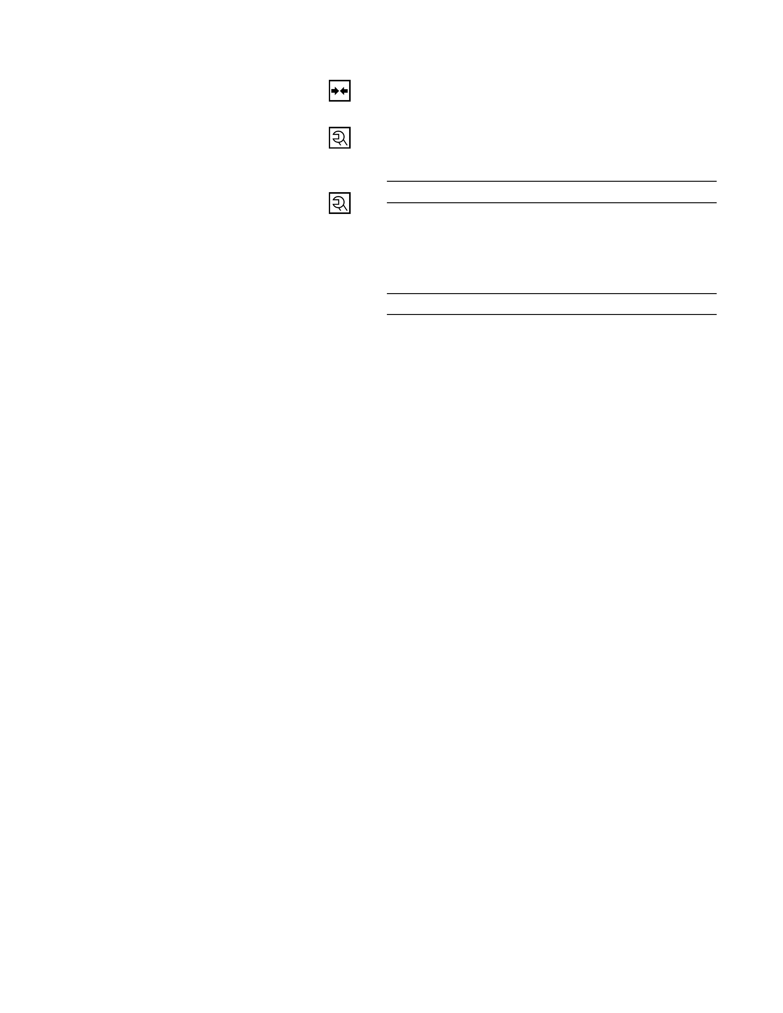
Inspect the lower end boot for damage or grease leak.
Move the ball joint as shown in the figure to confirm its
normal movement.
Inspect screw/taper area of ball for flaws.
If any defects are found by the above inspections, replace
the ball joint assembly with new one.
After moving the ball joint 4 or 5 times, attach nut then
measure the preload.
Upper Ball Joint Preload N·m (kg·m/lb·in)
0.5 – 3.2 (0.05 – 0.33 / 4.3 – 28.6)
If the above limits specified are exceeded, replace the
ball joint assembly.
INSTALLATION
3. Upper Ball Joint
2. Bolt, Nut and Washer
Upper Ball Joint Bracket Nut Torque N·m (kg·m/lb·ft)
57 (5.8 / 42)
1. Nut and Cotter Pin
Tighten the nut to the specified torque with just
enough additional torque to align cotter pin holes.
Install new cotter pin.
Upper Ball Joint Nut Torque N·m (kg·m/lb·ft)
98 (10.0 / 72)
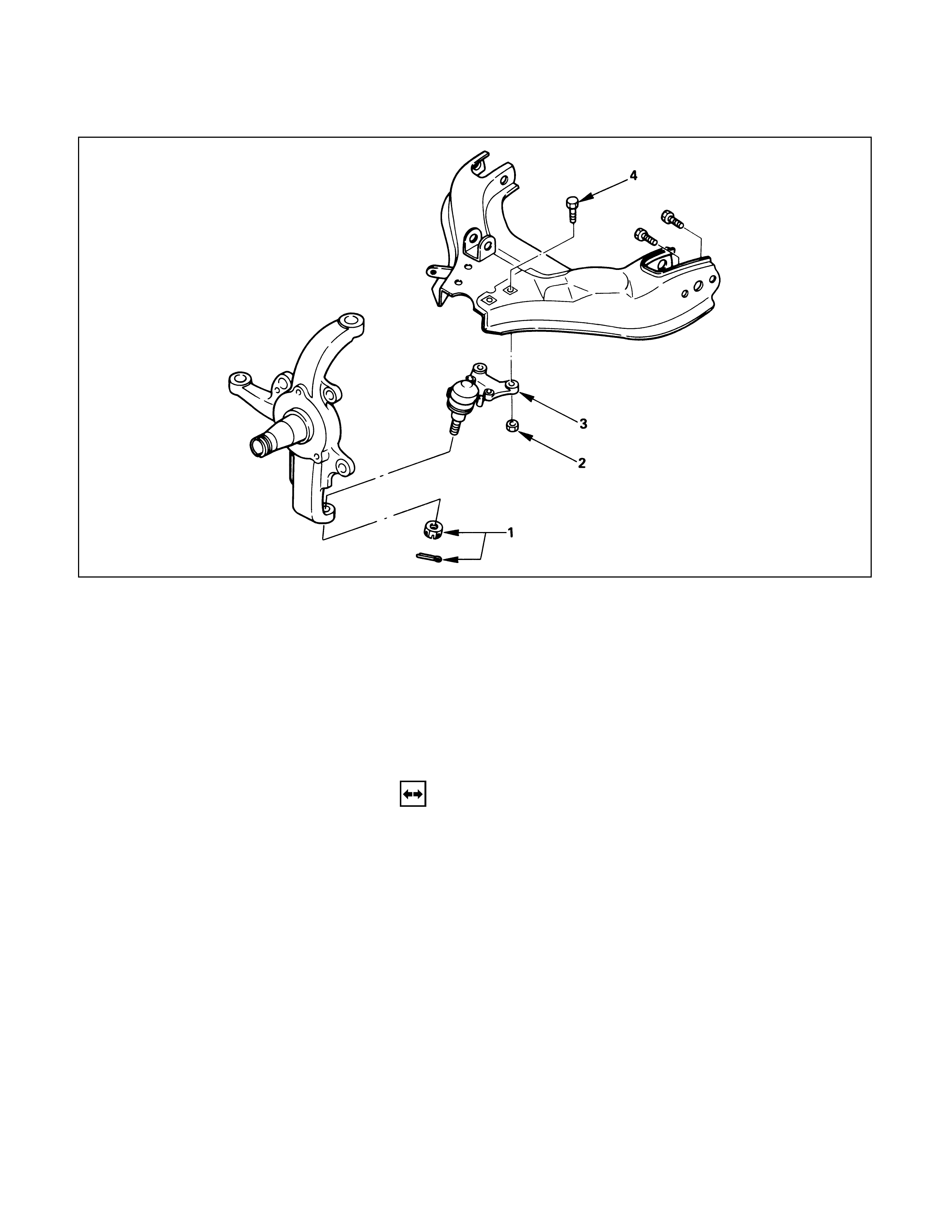
LOWER BALL JOINT
Removal Steps
1. Nut and cotter pin
2. Nut
3. Lower ball joint
4. Bolt
Installation Steps
4. Bolt
3. Lower ball joint
2. Nut
1. Nut and cotter pin
REMOVAL
Preparation:
1) Raise the vehicle and support the frame with suitable
safety stands.
2) Remove wheel and tire assembly. Refer to “Wheels
and Tires” in section 10.
3) Remove the outer track rod from the knuckle. Refer to
“Steering Linkage” in section 9B.
4) Remove the retaining ring from the front axle driving
shaft to release the shaft from hub. Refer to “Front
Axle” in section 4B.
5) Support lower control arm with a jack.
1. Nut and Cotter Pin
Remove the upper ball joint from the knuckle.
Remover: 5-8840-2005-0 (J-29107)
CAUTION:
Be careful not to break the ball joint boot.
2. Nut
3. Lower Ball Joint
4. Bolt
INSPECTION AND REPAIR
Make necessary parts replacement if wear, damage,
corrosion or any other abnormal conditions are found
through inspection.
Inspect the lower end boot for damage or grease leak.
Move the ball joint as shown in the figure to confirm its
normal movement.
Inspect screw/taper area of ball for flaws.
If any defects are found by the above inspections, replace
the ball joint assembly with new one.
After moving the ball joint 4 or 5 times, attach nut then
measure the preload.
Lower Ball Joint Preload N·m (kg·m/lb·in)
0.5 – 6.4 (0.05 – 0.65 / 4.3 – 56.4)
If the above limits specified are exceeded, replace the
ball joint assembly.
INSTALLATION
4. Bolt
3. Lower Ball Joint
2. Nut
Lower Ball Joint Bracket Nut Torque N·m (kg·m/lb·ft)
103 (10.5 / 76)
1. Nut and Cotter Pin
Tighten the nut to the specified torque with just
enough additional torque to align cotter pin holes.
Install new cotter pin.
Lower Ball Joint Nut Torque N·m (kg·m/lb·ft)
147 (15.0 / 108)