
GENERAL DESCRIPTION
Stabiliser Bar
Center Link
Shock Absorber
Trailing Link
Lateral Rod
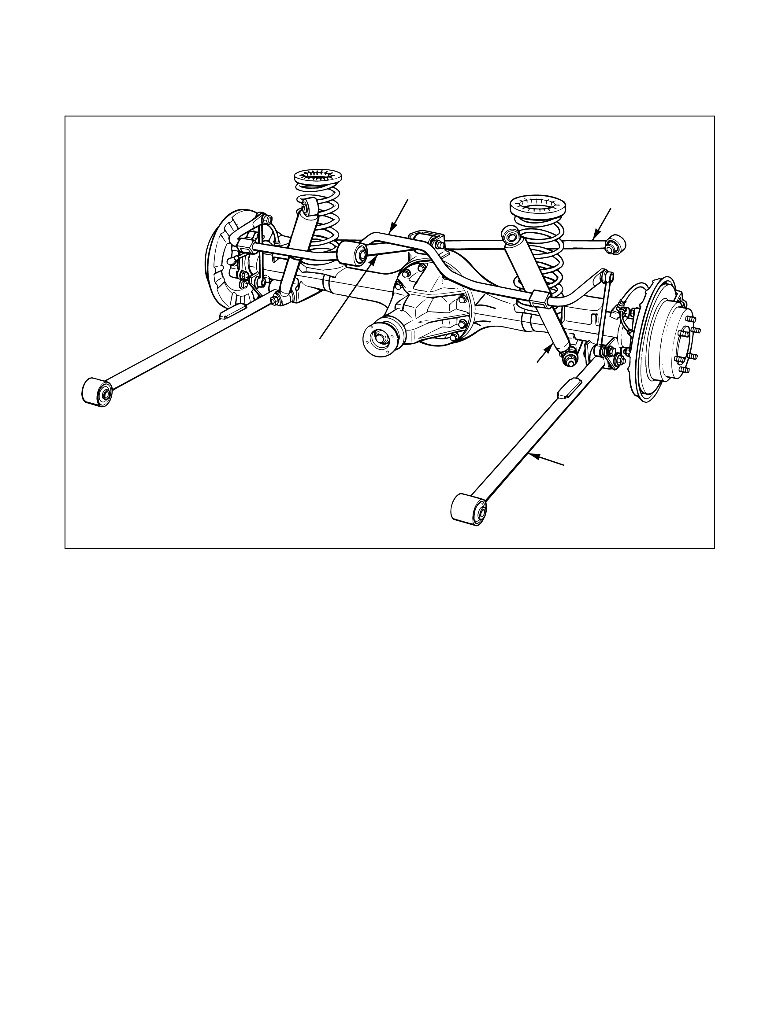
The rear suspension is a 4-link, coil spring type
suspension with a stabiliser, consisting of two
trailing links, center link, lateral rod, shock
absorber, and stabiliser. In this suspension, the
links are specially arranged to enable the rear axle
to move freely, thereby expanding suspension
stroke, reducing friction, and improving lateral
rigidity and roll control. All these result in
improved stability, riding comfort, and rough road
maneuverability.
Each link connects the axle housing with the frame
through a rubber bushing. The axle housing is
supported by the trailing links and center link
longitudinally and by the lateral rod latitudinally.
C03RW003
ON-VEHICLE SERVICE
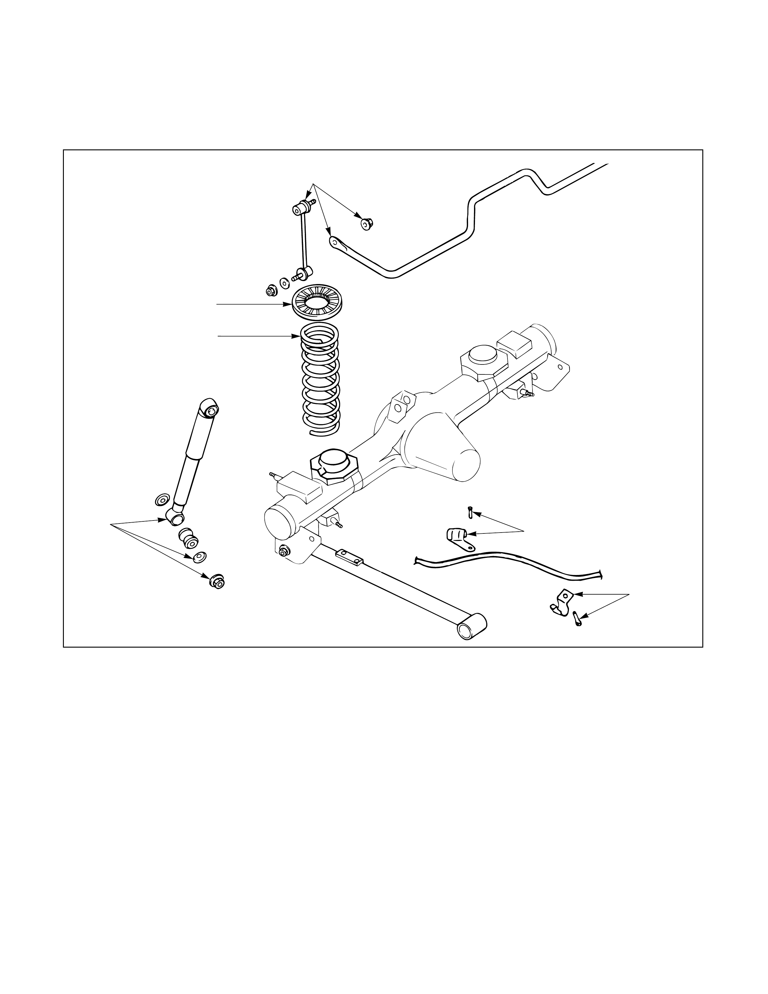
COIL SPRING
5
2
4
5
31
1
Removal Steps
1. Parking brake cable bracket
2. Stabilizer bar
3. Shock absorber
4. Insulator
5. Coil spring
Installation Steps
5. Coil spring
4. Insulator
3. Shock absorber
2. Stabilizer bar
1. Parking brake cable bracket
460RW024
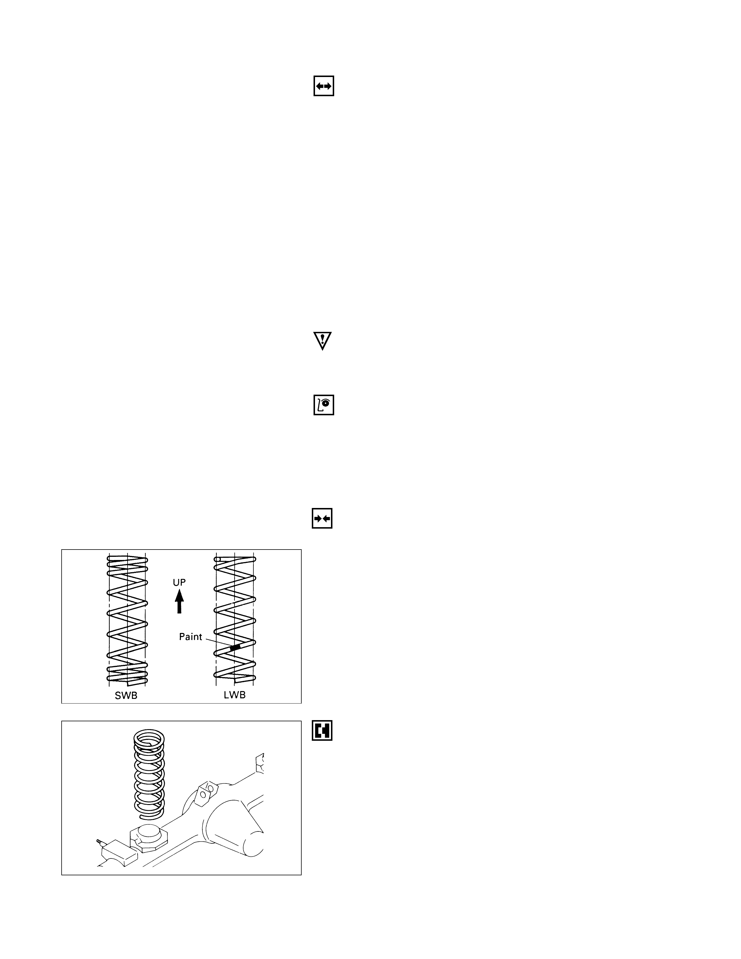
INSTALLATION
5. Coil Spring
Make sure that the coil spring is installed in the proper
position.
REMOVAL
Preparation:
1) Raise the vehicle and support the frame with suitable
safety stands.
2) Support the rear axle case with a jack.
1. Parking Brake Cable Bracket
Remove the parking brake cable from the trailing link.
2. Stabilizer Bar
Disconnect the stabilizer bar at the stabilizer link.
3. Shock Absorber
Remove the shock absorber from the axle case.
4. Insulator
5. Coil Spring
Remove the insulator and coil spring while lowering
the rear axle case.
CAUTION:
Be sure not to let the brake hose, parking brake cable,
and breather hose extend to their full length.
INSPECTION AND REPAIR
Make necessary correction or parts replacement if wear,
damage, corrosion or any other abnormal condition are
found through inspection.
•Coil spring
•Insulator
Fit the end of the coil spring to the coil spring seat and
mount the coil spring on the rear axle case.
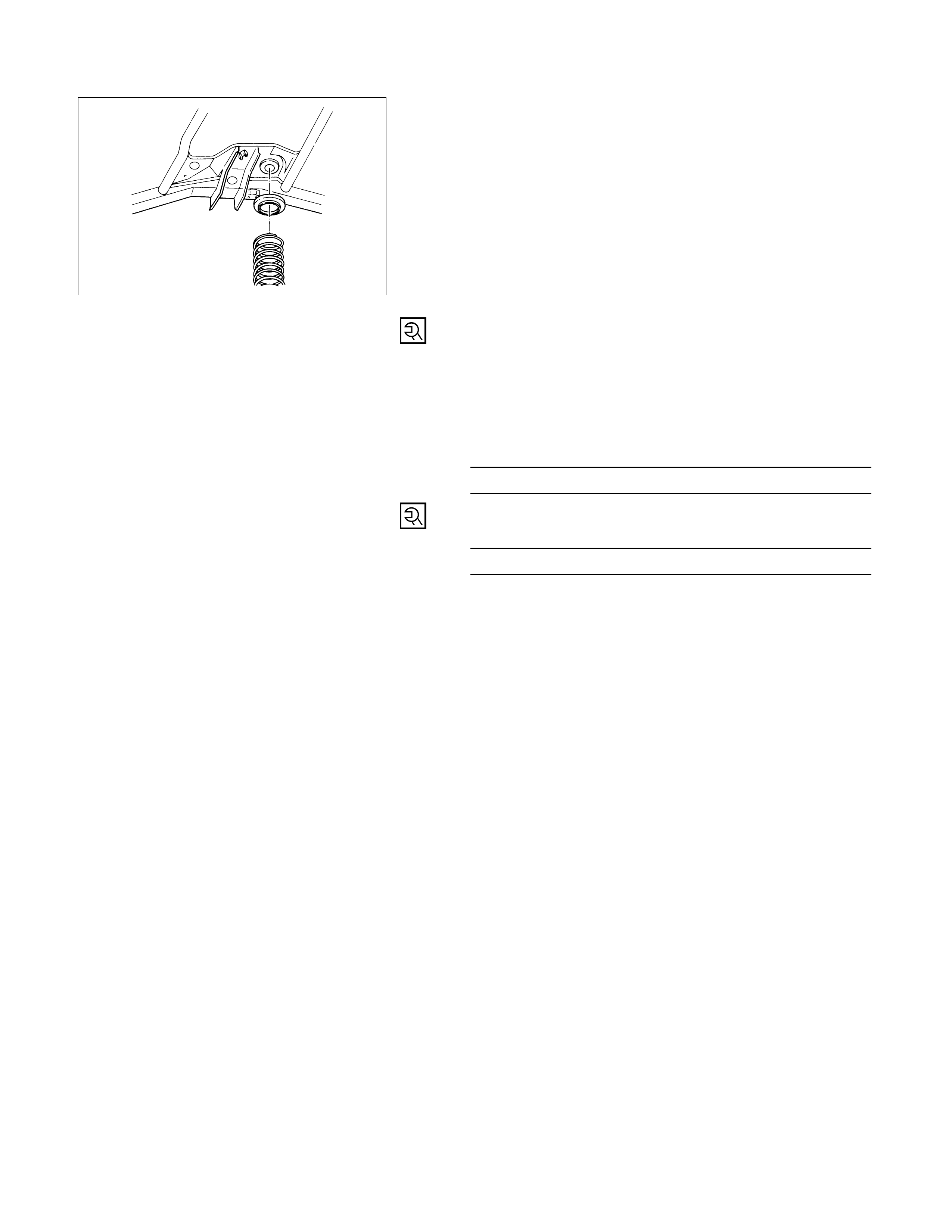
4. Insulator
Install the insulator on the coil spring. Jack up the axle
case gently with the top of the coil spring to set the
spring seat on the frame side.
3. Shock Absorber
Tighten the nut lightly, and retighten to the specified
torque after the vehicle is at curb height.
NOTE:
When mounting shock absorber, be sure not to use
grease on bushings or any other nearby part.
Shock Absorber Nut Torque N·m (kg·m/lb·ft)
78 (8.0 / 58)
2. Stabilizer Bar
Stabilizer Bar Nut Torque N·m (kg·m/lb·ft)
50 (5.1 / 37)
1. Parking Brake Cable Bracket
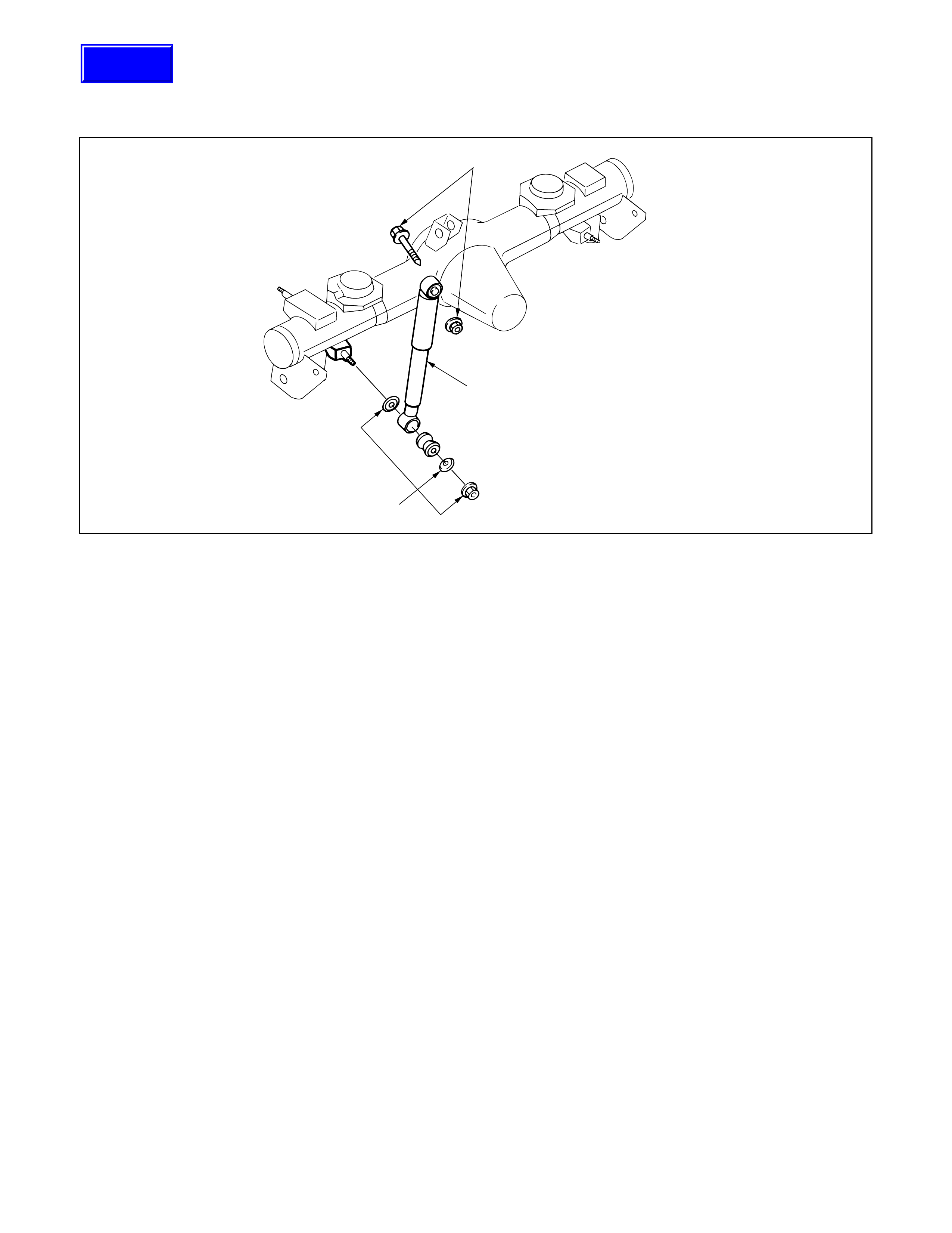
REMOVAL
1. Nut and Washer
2. Bolt, Nut and Washer
3. Shock Absorber
INSPECTION AND REPAIR
Make necessary correction or parts replacement if wear,
damage, corrosion or any other abnormal condition are
found through inspection.
•Shock absorber
•Rubber bushing (Axle side)
INSTALLATION
3. Shock Absorber
NOTE:
When mounting rubber bushings, be sure not to use
grease on bushings or any other nearby part.
2. Bolt, Nut and Washer
NOTE:
Tighten the bolt and nut lightly, and retighten to the
specified torque after the vehicle is at curb height.
Shock Absorber Nut Torque N·m (kg·m/lb·ft)
95 (9.7 / 70)
1. Nut and Washer
NOTE:
Tighten the bolt and nut lightly, and retighten to the
specified torque after the vehicle is at curb height.
Shock Absorber Nut Torque N·m (kg·m/lb·ft)
78 (8.0 / 58)
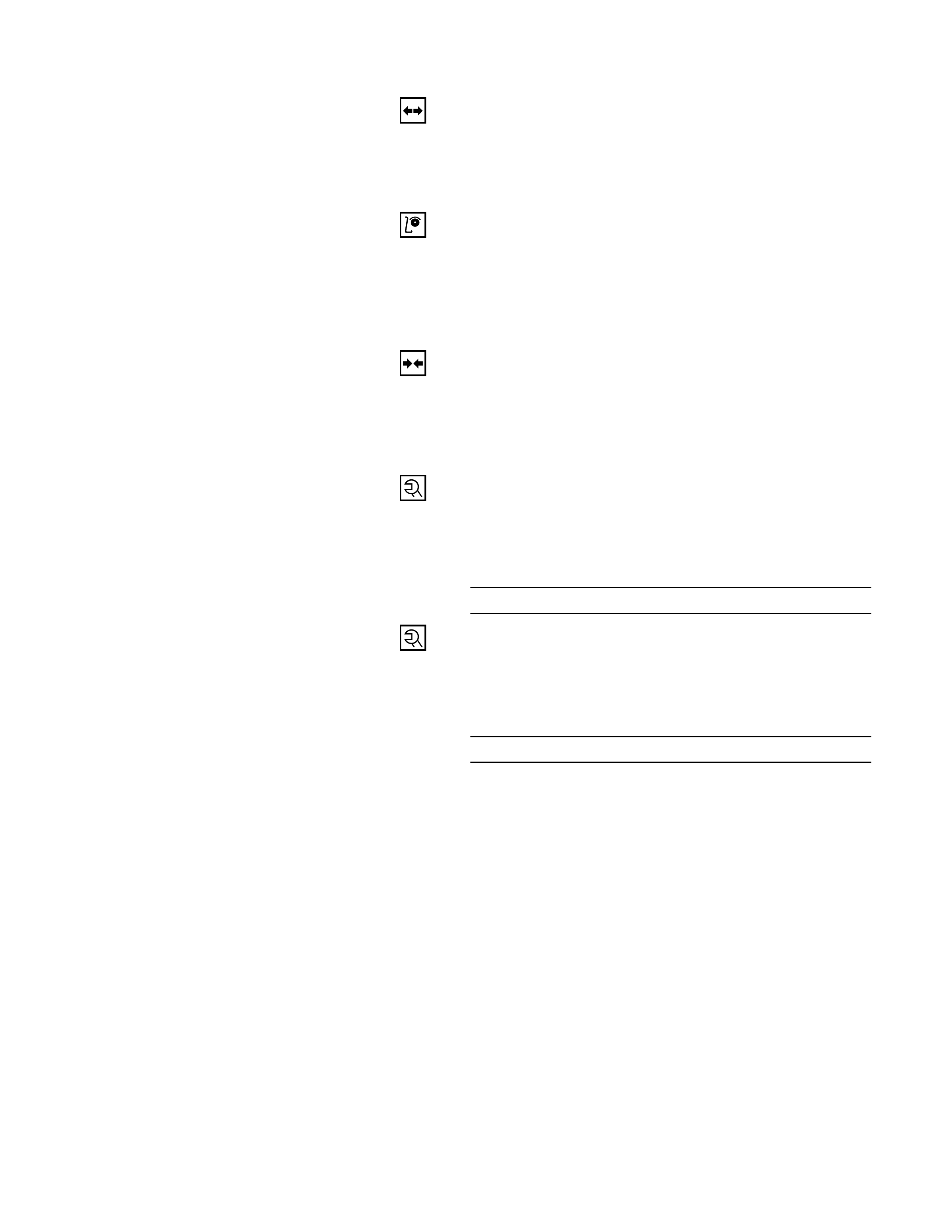
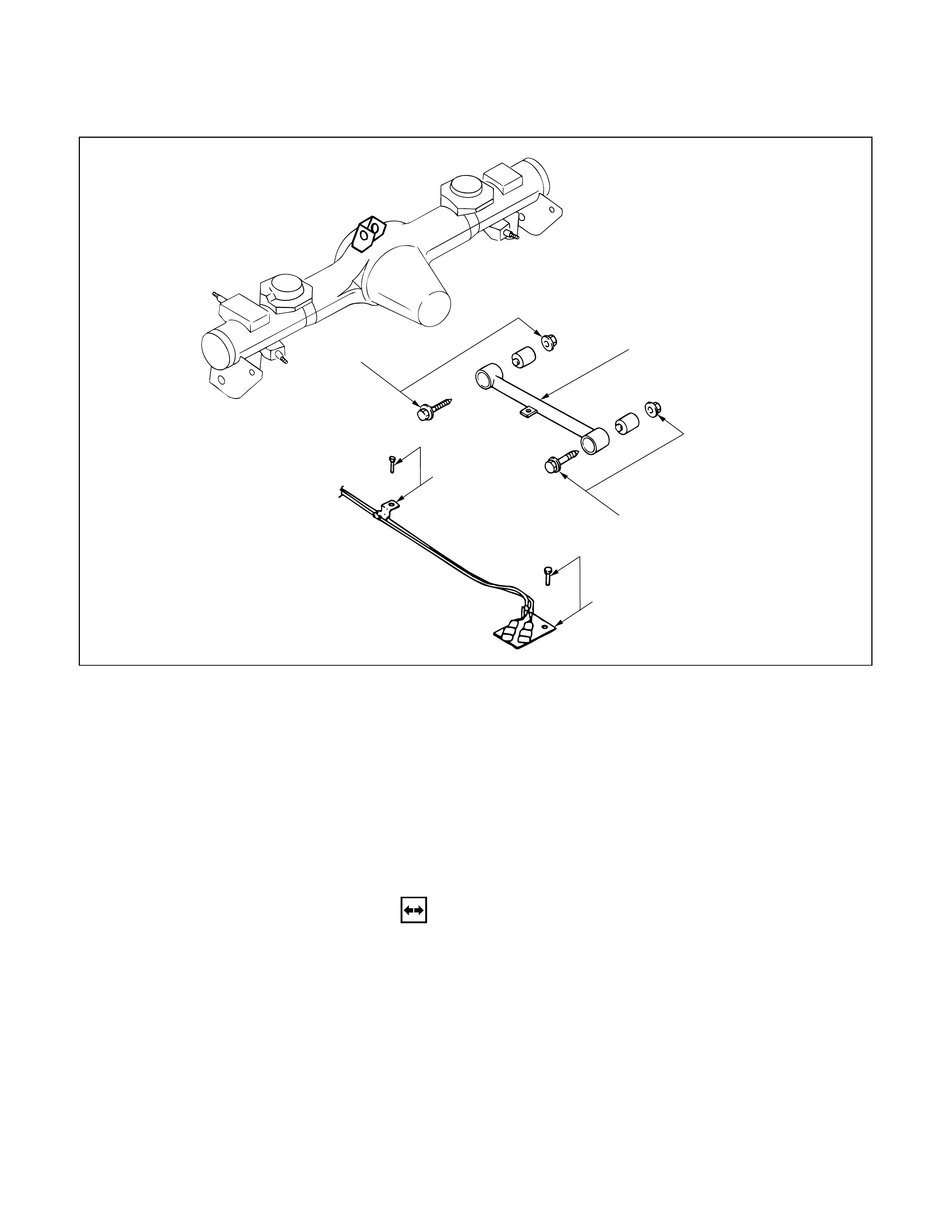
TRAILING LINK
2
32
1
Removal Steps
1. Parking brake cable
2. Bolt and nut
3. Trailing link
Installation Steps
3. Trailing link
2. Bolt and nut
1. Parking brake cable
REMOVAL
1. Parking Brake Cable
Remove the parking brake cable from the trailing link.
2. Bolt and Nut
3. Trailing Link
460RW025
INSPECTION AND REPAIR
Make necessary correction or parts replacement if wear,
damage, corrosion or any other abnormal condition are
found through inspection.
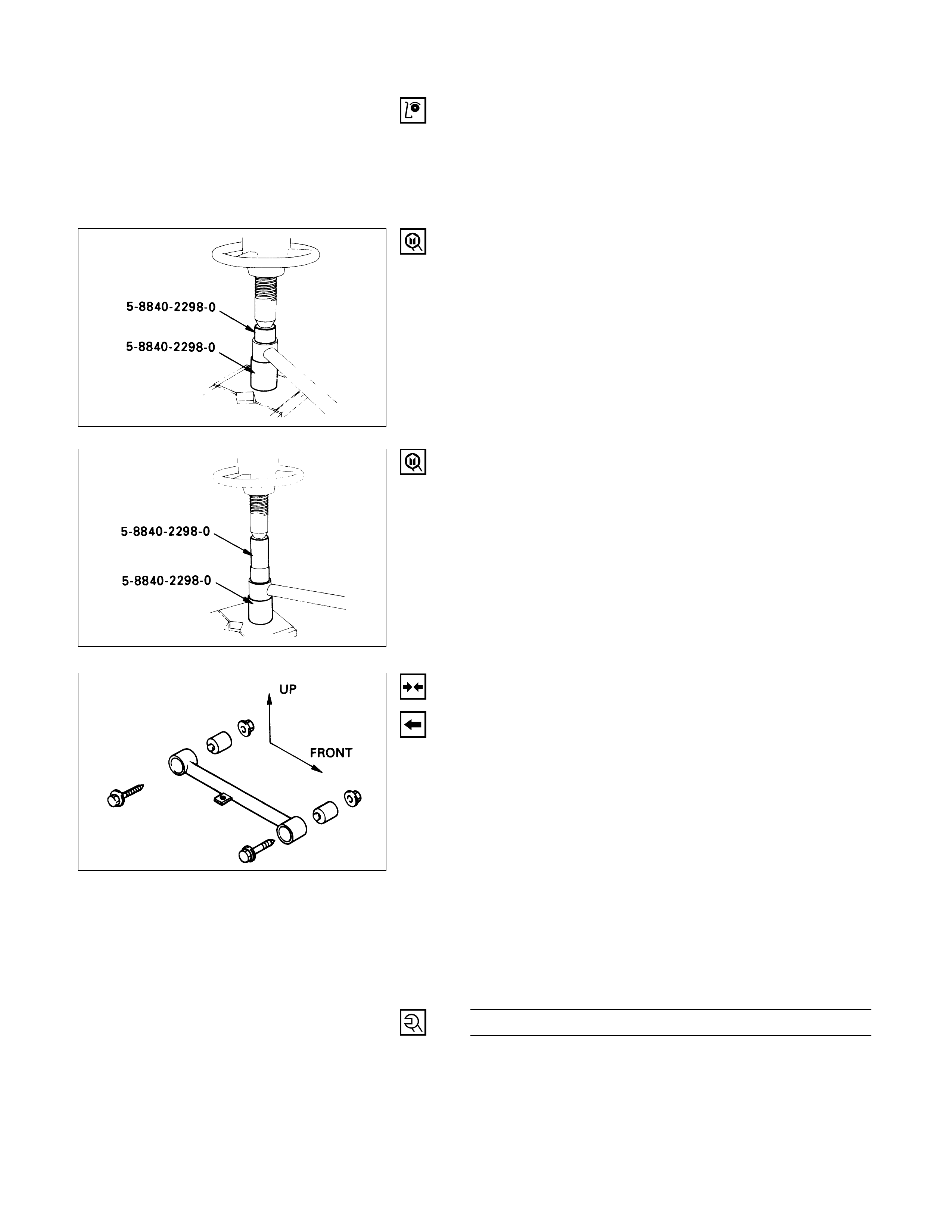
1. Trailing Link
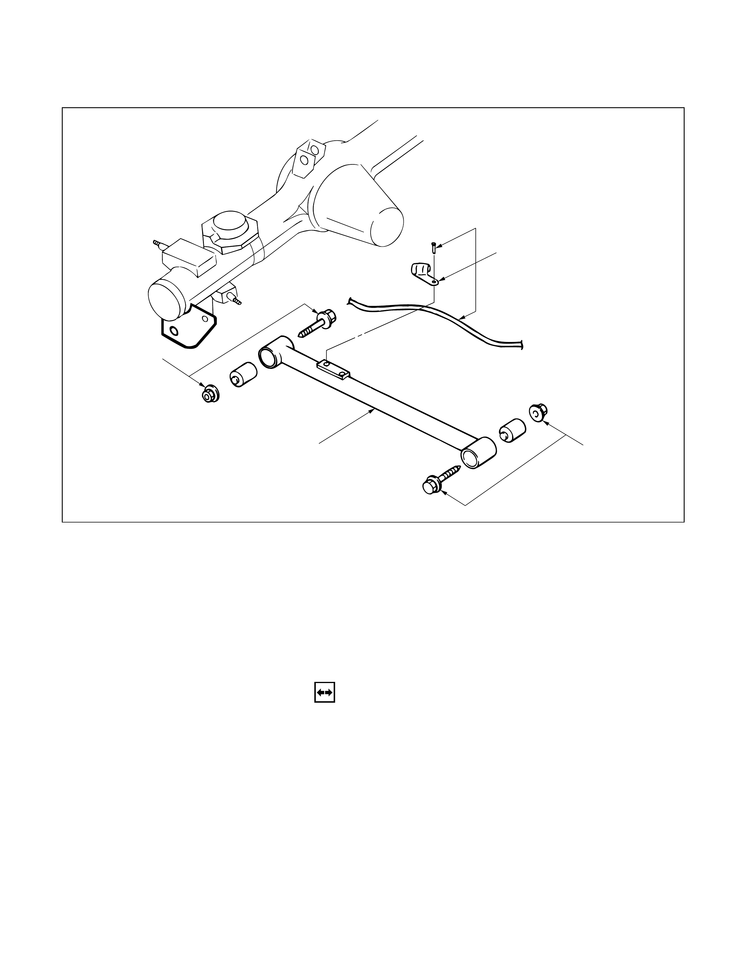
2. Rubber Bushing
Remove the rubber bushing.
Remover: 5-8840-2298-0 (J-39214)
Install the rubber bushing.
Installer: 5-8840-2298-0 (J-39214)
NOTE:
When mounting rubber bushings, be sure not to use
grease on bushings or any other nearby part.
INSTALLATION
3. Trailing Link
Make sure that the trailing link is in its correct
position.
NOTE:
When mounting trailing link, be sure not to use
grease on bushings or any other nearby part.
2. Bolt and Nut
NOTE:
Tighten the bolts and nuts lightly, and retighten to
the specified torque after the vehicle is at curb height.
Trailing Link Nut Torque N·m (kg·m/lb·ft)
137 (14.0 / 101)
1. Parking Brake Cable
CAUTION:
The parking brake cable should not be overstrained or
slackened.
CENTER LINK
3
3
4
1
2
Removal Steps
1. Speed sensor cable
(If equipped with ABS)
2. Speed sensor cable bracket
(If equipped with ABS)
3. Bolt and nut
4. Center link
Installation Steps
4. Center link
3. Bolt and nut
2. Speed sensor cable bracket
(If equipped with ABS)
1. Speed sensor cable
(If equipped with ABS)
REMOVAL
1. Speed Sensor Cable (If equipped with ABS)
Remove the speed sensor cable from the center link.
2. Speed Sensor Cable Bracket (If equipped with ABS)
Remove the speed sensor cable bracket from the
frame.
3. Bolt and Nut
4. Center Link
460RW026
INSPECTION AND REPAIR
Make necessary correction or parts replacement if wear,
damage, corrosion or any other abnormal condition are
found through inspection.
1. Center Link
2. Rubber Bushing
Remove the rubber bushing.
Remover: 5-8840-2298-0 (J-39214)
Install the rubber bushing.
Installer: 5-8840-2298-0 (J-39214)
NOTE:
When mounting rubber bushings, be sure not to use
grease on bushings or any other nearby part.
INSTALLATION
4. Center Link
Make sure that the center link is in its correct position.
NOTE:
When mounting center link, be sure not to use grease
on bushings or any other nearby part.
3. Bolt and Nut
NOTE:
Tighten the bolts and nuts lightly, and retighten to
the specified torque after the vehicle is at curb height.
Center Link Nut Torque N·m (kg·m/lb·ft)
137 (14.0 / 101)
2. Speed Sensor Cable Bracket
1. Speed Sensor Cable
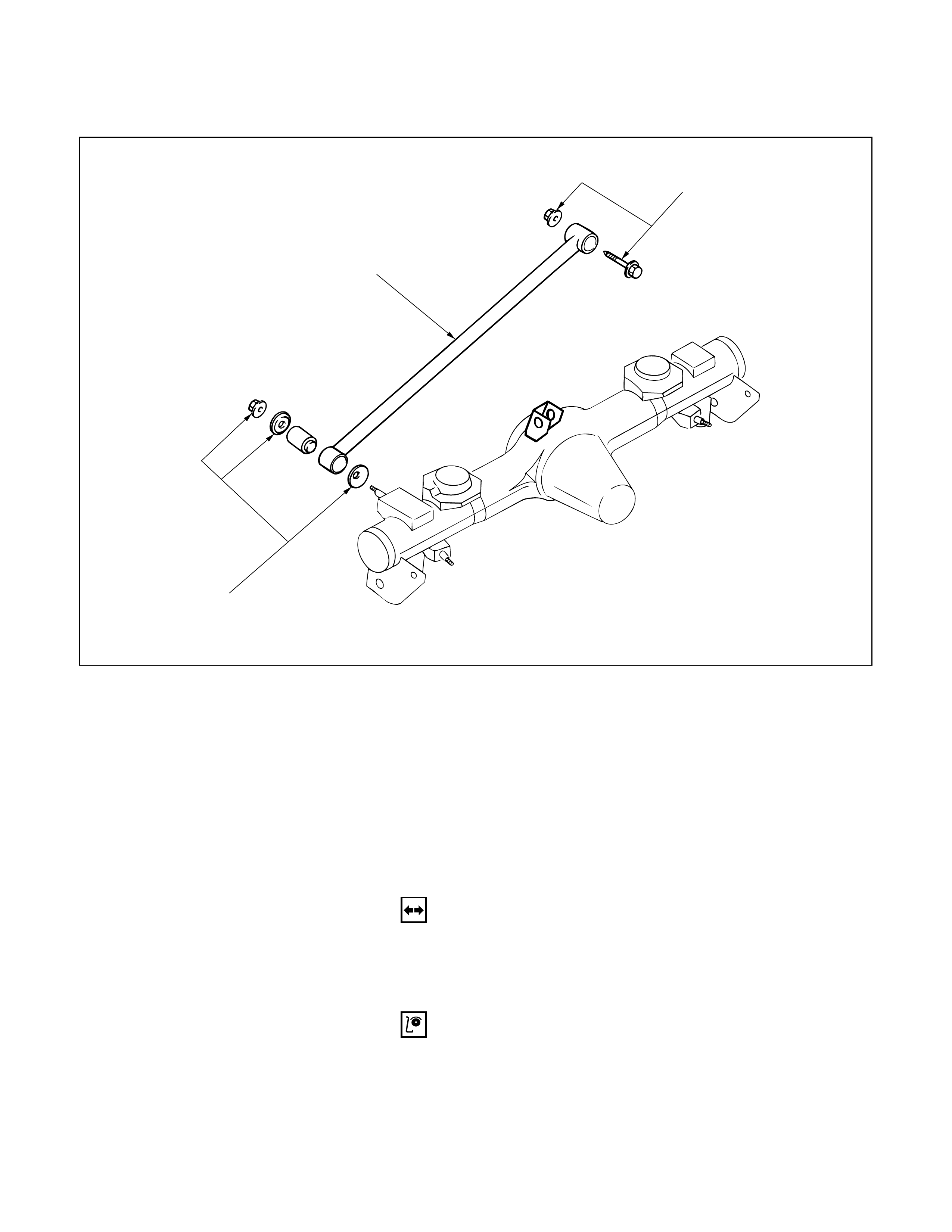
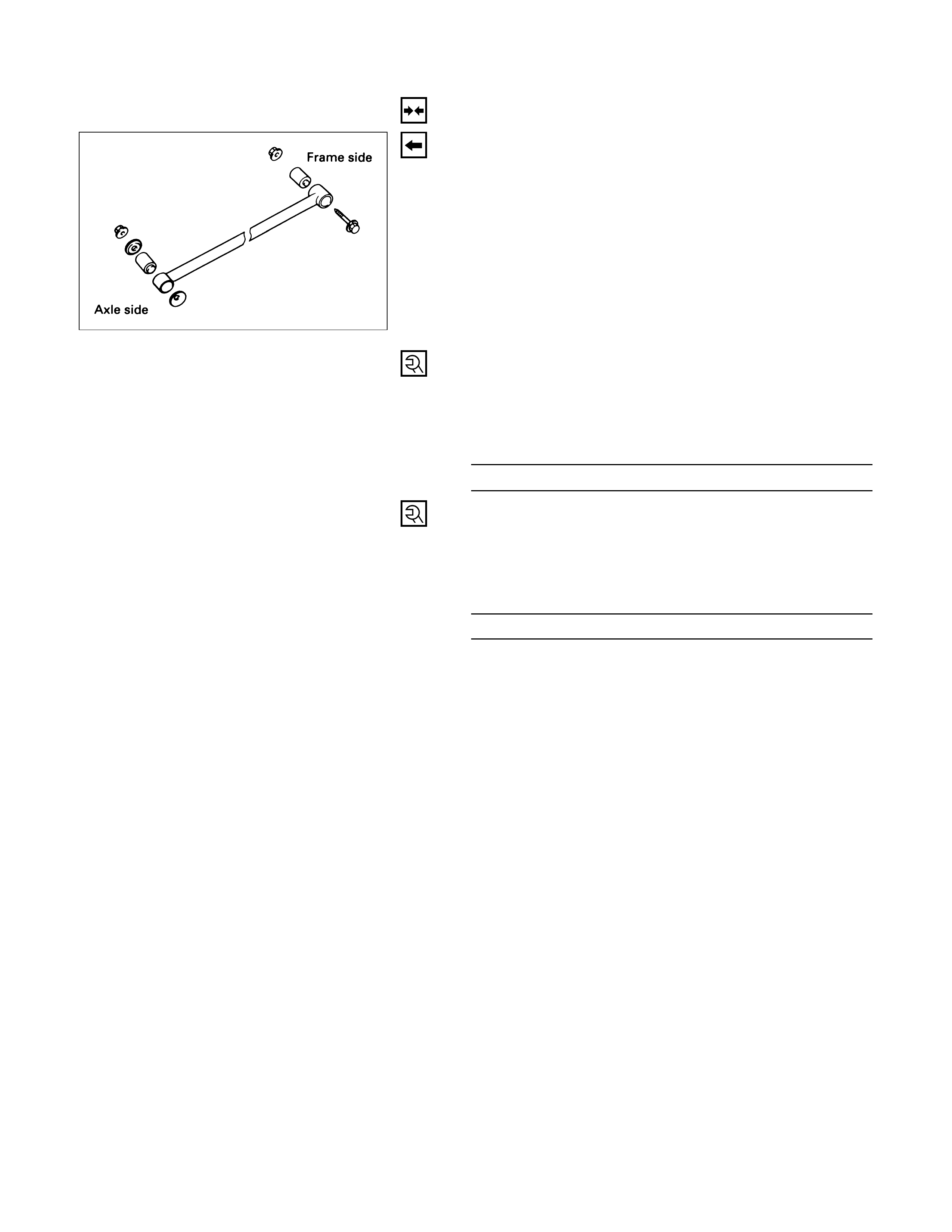
LATERAL ROD
1
3
2
Removal Steps
1. Nut and washer
2. Bolt and nut
3. Lateral rod
Installation Steps
3. Lateral rod
2. Bolt and nut
1. Nut and washer
REMOVAL
1. Nut and Washer
2. Bolt and Nut
3. Lateral Rod
INSPECTION AND REPAIR
Make necessary correction or parts replacement if wear,
damage, corrosion or any other abnormal condition are
found through inspection.
1. Lateral Rod
460RW027
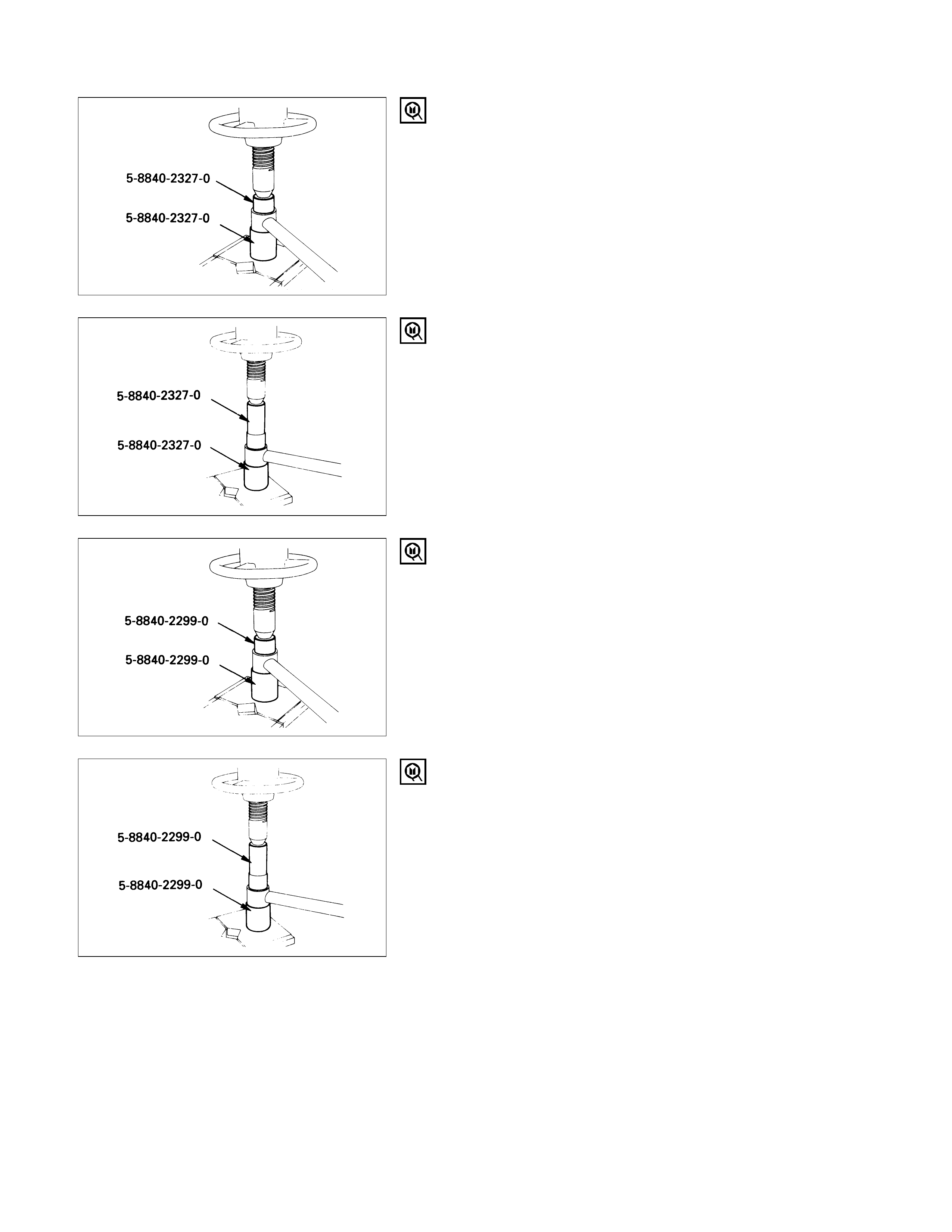
2. Rubber Bushing (Axle side)
Remove the rubber bushing (Axle side).
Remover: 5-8840-2327-0 (J-39792)
Install the rubber bushing (Axle side).
Installer: 5-8840-2327-0 (J-39792)
NOTE:
When mounting rubber bushings, do not use grease
on bushings or any other nearby parts.
3. Rubber Bushing (Frame side)
Remove the rubber bushing (Frame side).
Remover: 5-8840-2299-0 (J-39215)
Install the rubber bushing (Frame side).
Installer: 5-8840-2299-0 (J-39215)
NOTE:
When mounting rubber bushings, do not use grease
on bushings or any other nearby parts.
INSTALLATION
3. Lateral Rod
Make sure that the lateral rod is in its correct position.
NOTE:
When mounting lateral rod, be sure not to use grease
on bushings or any other nearby part.
2. Bolt and Nut
NOTE:
Tighten the bolt and nut lightly, and retighten to the
specified torque after the vehicle is at curb height.
Lateral Rod Nut Torque N·m (kg·m/lb·ft)
137 (14.0 / 101)
1. Nut and Washer
NOTE:
Tighten the nut lightly, and retighten to the specified
torque after the vehicle is at curb height.
Lateral Rod Nut Torque N·m (kg·m/lb·ft)
78 (8.0 / 58)

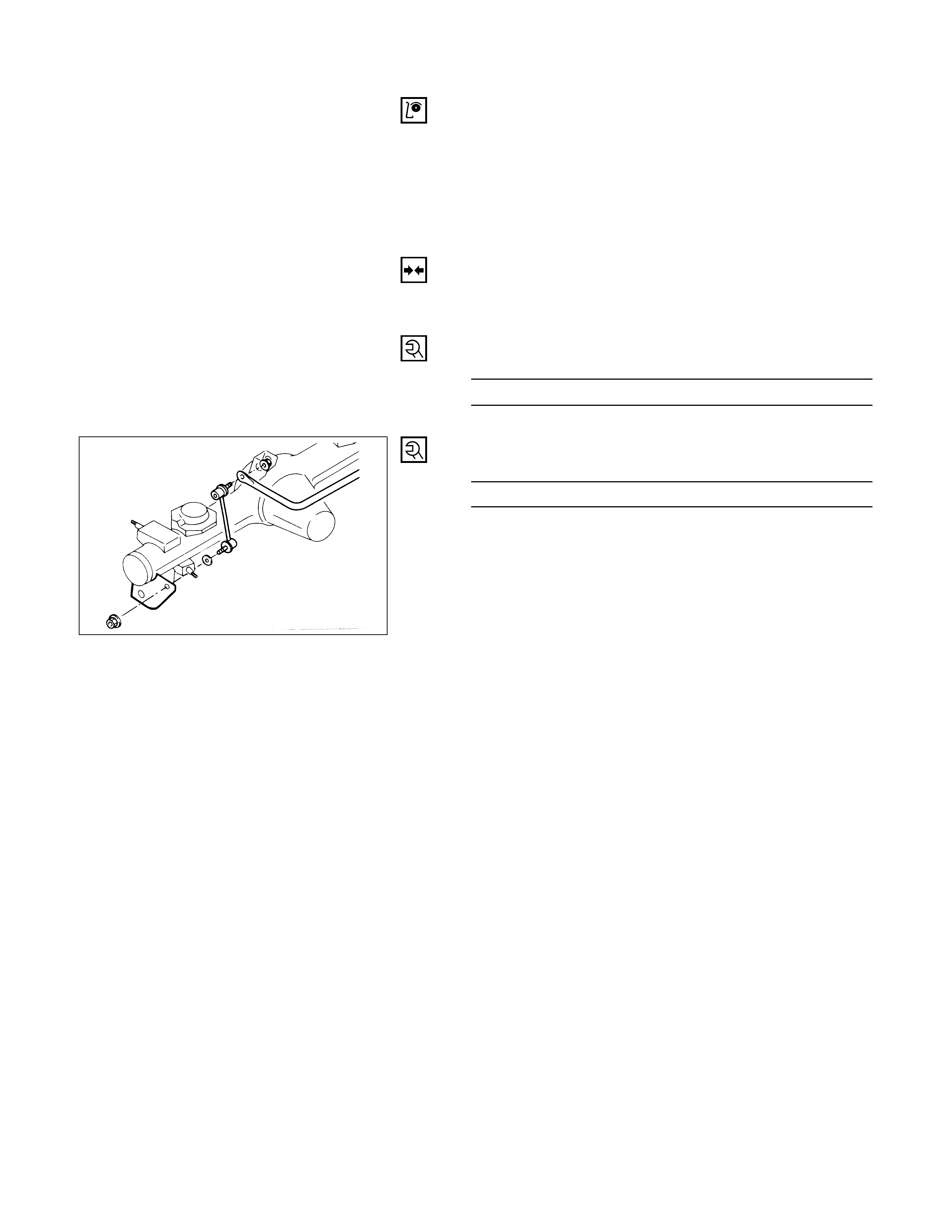
STABILISER BAR
1
5
2
4
4
3
3
2
Removal Steps
1. Nut and washer
2. Link
3. Bracket
4. Rubber bushing
5. Stabiliser bar
Installation Steps
5. Stabiliser bar
4. Rubber bushing
3. Bracket
2. Link
1. Nut and washer
REMOVAL
Preparation:
1) Raise the vehicle and support the frame with suitable
safety stands.
2) Remove wheel and tire assembly.
Refer to "Wheels and Tyres" in section 10 .
1. Nut and Washer
CAUTION:
Be careful not to break the ball joint boot.
2. Link
3. Bracket
4. Rubber Bushing
5. Stabiliser Bar
460RW028
INSPECTION AND REPAIR
Make necessary correction or parts replacement if wear,
damage, corrosion or any other abnormal condition are
found through inspection.
• Stabiliser bar
•Rubber bushing
•Link ball joint
INSTALLATION
5. Stabiliser Bar
4 Rubber Bushing
3. Bracket
Bracket Bolt Torque N·m (kg·m/lb·ft)
22 (2.2 / 16)
2. Link
1. Nut and Washer
Link Nut Torque N·m (kg·m/lb·ft)
50 (5.1 / 37)