
SECTION 4A - SHIFT ON THE FLY
Service Precaution
Shift on the Fly System (Lever Type)
Outline of Shift on the Fly System (Lever Type)
Shift on the Fly Vacuum Piping and Electric Equipment
(Lever Control Type)
Vacuum Piping Diagram
VSV Assembly, Actuator Assembly
Vacuum Tank
Inspection and Repair
Shift on the Fly System (Push Button Type)
Outline of Shift on the Fly System (Push Button
Type)
4WD Indicator Lamp Function
Diagnosis
Front Axle Diagnosis
Shift on the Fly Vacuum Hoses and Electric Equipment
(Push Button Type)
Vacuum Hose Routing Diagram
VSV Assembly, Actuator Assembly
Vacuum Tank
Inspection and Repair
4WD Control Unit (For Push Button Type)
4WD Control Unit Associated Parts
Removal
Installation
Service Precaution
WARNING: IF EQUIPPED WITH A SUPPLEMENTAL
RESTRAINT SYSTEM (SRS), REFER TO THE SRS
COMPONENT AND WIRING LOCATION VIEW IN
ORDER TO DETERMINE WHETHER YOU ARE
PERFORMING SERVICE ON OR NEAR THE SRS
COMPONENTS OR THE SRS WIRING. WHEN YOU
ARE PERFORMING SERVICE ON OR NEAR THE
SRS COMPONENTS OR THE SRS WIRING, REFER
TO THE SRS SERVICE INFORMATION. FAILURE TO
FOLLOW WARNINGS COULD RESULT IN POSSIBLE
AIR BAG DEPLOYMENT, PERSONAL INJURY, OR
OTHERWISE UNNEEDED SRS SYSTEM REPAIRS.
CAUTION: Always use the correct fastener in the
proper location. When you replace a fastener, use
ONLY the exact part number for that application.
HOLDEN will call out those fasteners that require a
replacement after removal. HOLDEN will also call
out the fasteners that require thread lockers or
thread sealant. UNLESS OTHERWISE SPECIFIED,
do not use supplemental coatings (Paints, greases,
or other corrosion inhibitors) on threaded fasteners
or fastener joint interfaces. Generally, such
coatings adversely affect the fastener torque and
the joint clamping force, and may damage the
fastener. When you install fasteners, use the correct
tightening sequence and specifications. Following
these instructions can help you avoid damage to
parts and systems.

Shift on the Fly System (Lever Type)
Outline of Shift on the Fly System (Lever
Type)
The shift on the fly system (Lever type) switches
between 2 wheel drive (2WD) and 4 wheel drive (4WD)
by driver's shifting the transfer control lever on the floor.
This system controls the following operations:
1. Connecting front wheels to, and disconnecting them
from, the front axles by vacuum actuator.
2. Instrument panel indicator lamp.
3. 4WD signal to Electronic Hydraulic Control Unit for
the ABS calibration (If equipped).
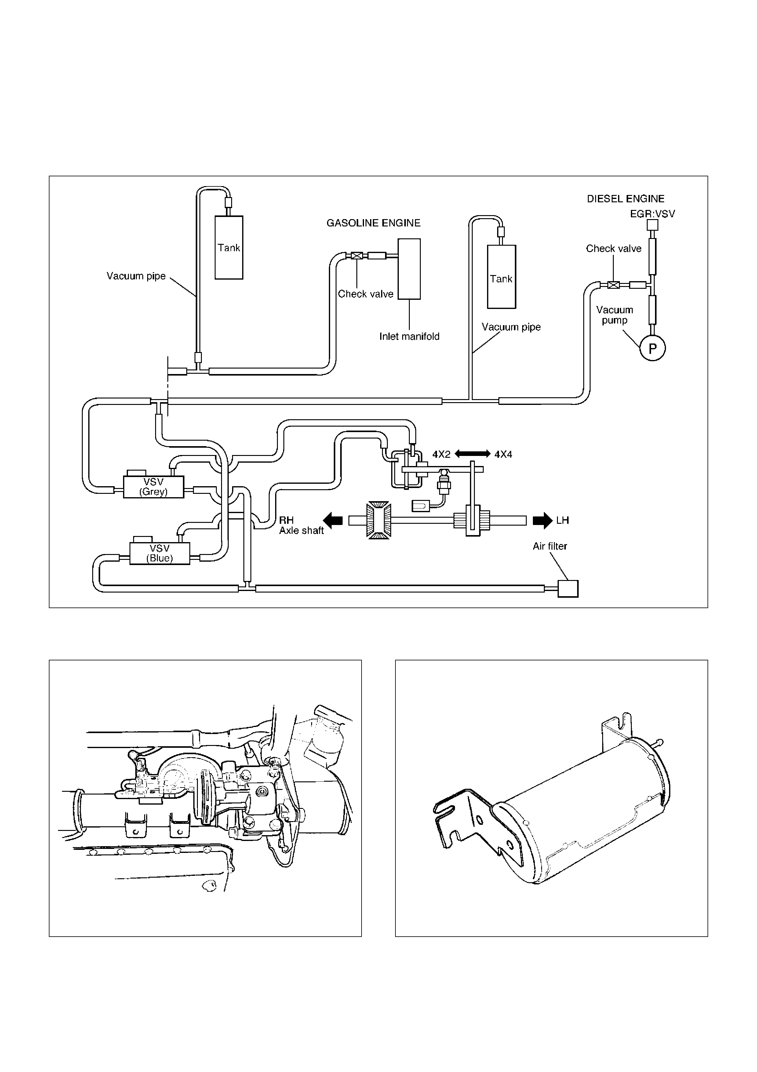
Shift on the Fly Vacuum Piping and Electric Equipment
(Lever Control Type)
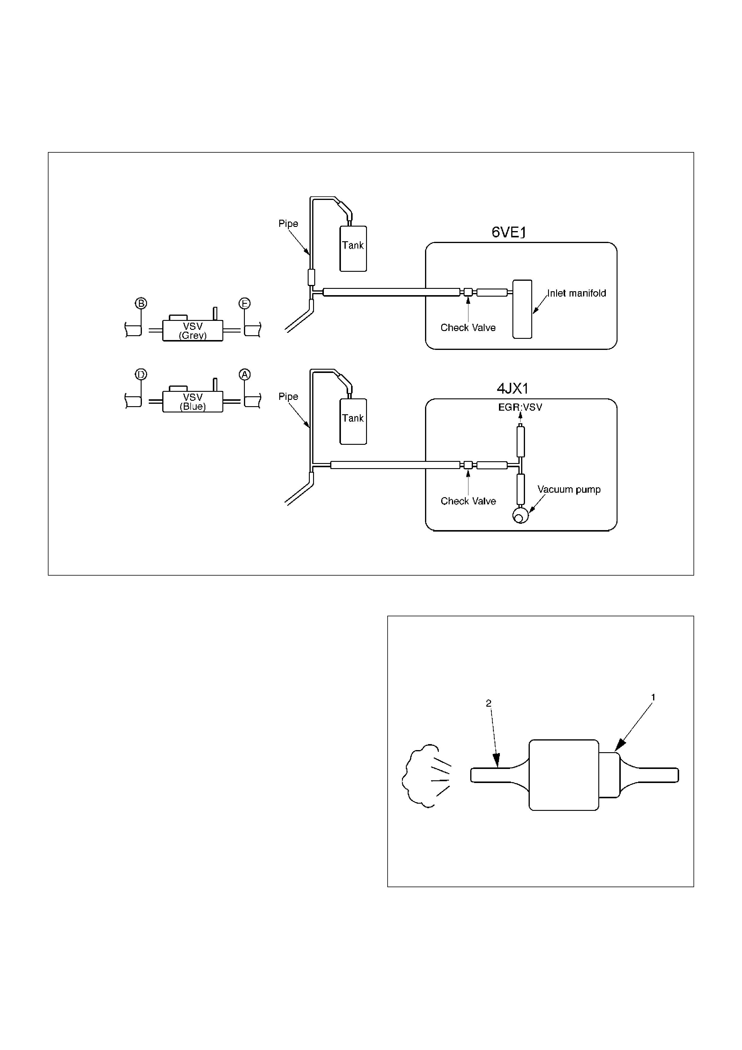
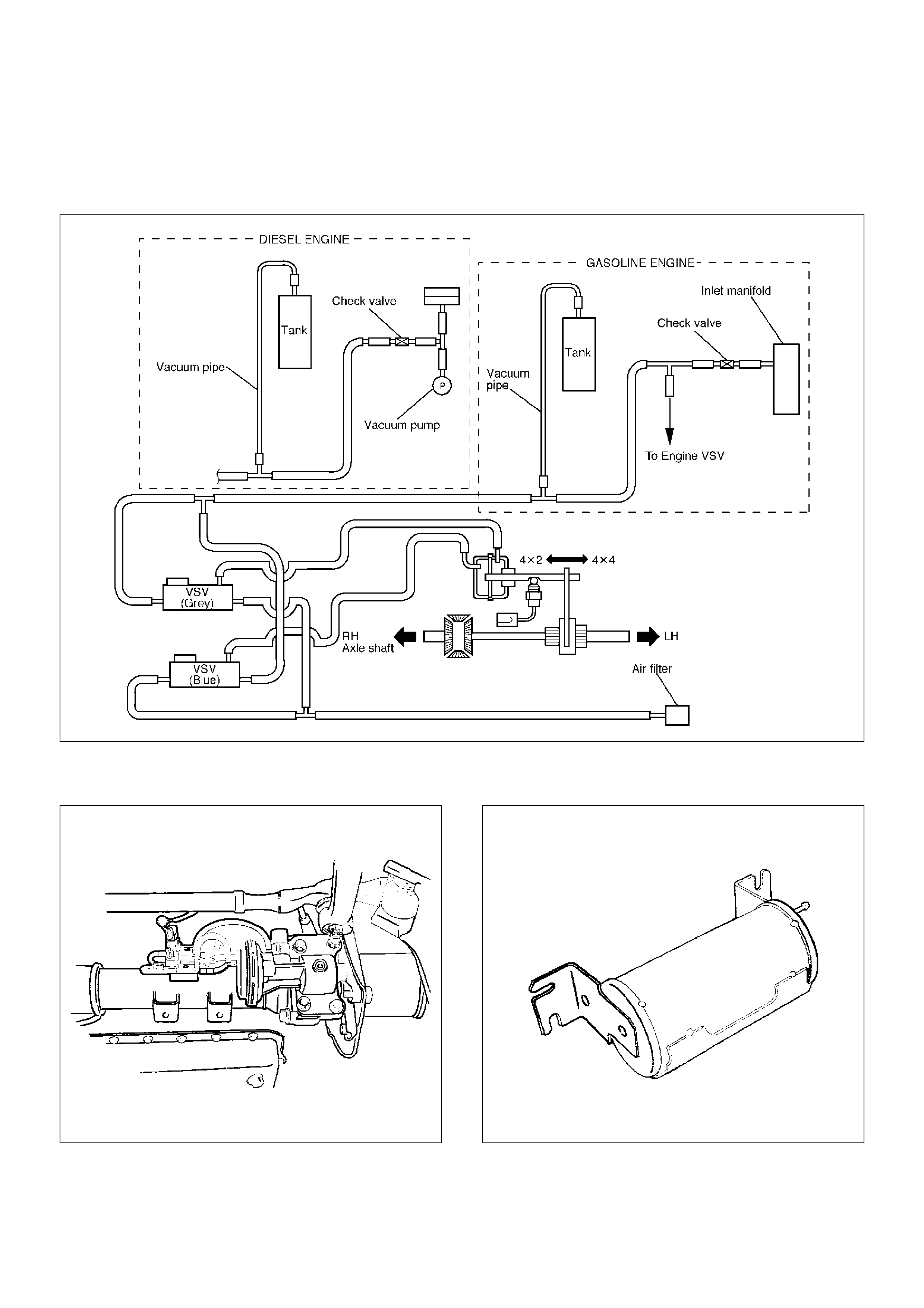
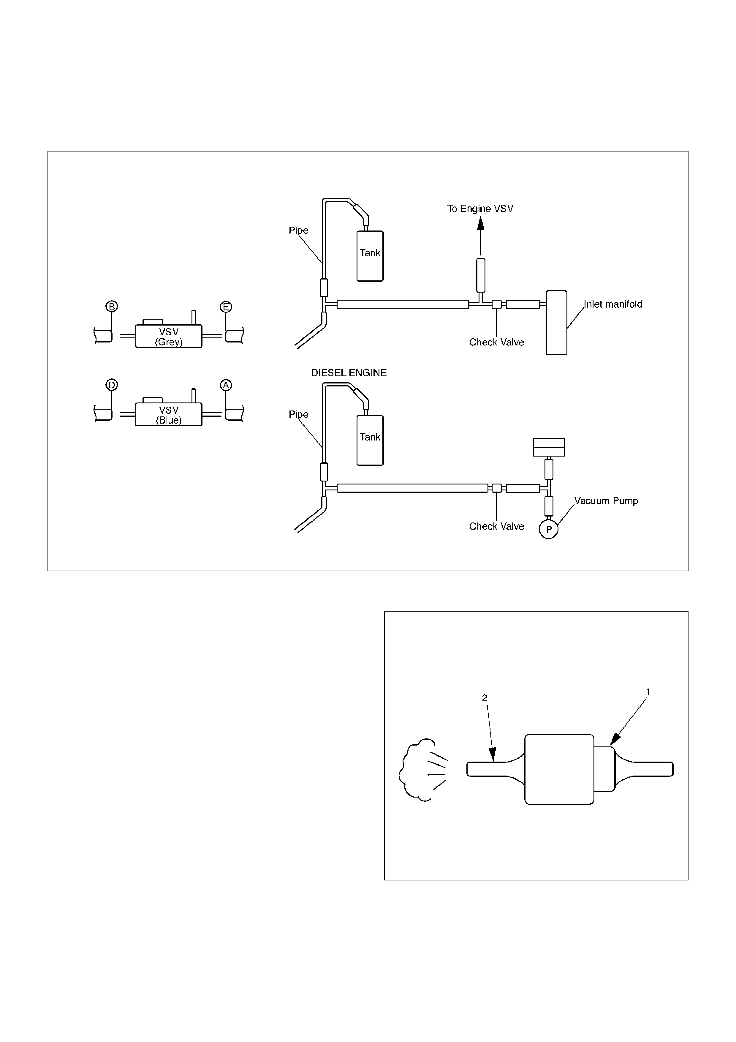
Vacuum Piping Diagram
C04RW015
VSV Assembly, Actuator Assembly
412RS032
Vacuum Tank
412RS033
Inspection and Repair
Vacuum Piping
C04RW016
1. Pull out the Hose A in figure and install a vacuum
gauge.
2. Plug up Hose B in figure to prevent the leak of
vacuum.
3. Start the engine and measure vacuum 2 or 3
minutes afterward.
4. Repeat 1) and 2) but with Hose A plugged and Hose
B pulled out.
5. If vacuum measures –400mmHg, or if it shows a
sudden drop immediately after engine stop, inspect
the hose, tank, and pipe for damage.
NOTE: Be careful not to permit the entry of dust and
water during inspection.
6. Pull out Hose D in above illustration.
7. Plug Hose E in above illustration.
8. Make sure that Hose D in above illustration is under
atmospheric pressure.
9. Pull out Hose E and plug Hose D, and make sure
that Hose E is under atmospheric pressure.
10. If Check 8) or 9) has revealed stoppage, check and
see that there is no bend, foreign matter in the hose
or in the filter. If there is trouble, repair or replace.
Check Valve
C04RS004
1. Apply vacuum from the orange colored side(1).
Vacuum:–400mmHg
2. Check leakage of vacuum.
3. Make sure that vacuum cannot be applied from the
black colored side(2).
4. If vacuum is not applicable as much as –400mmHg,
and if there is resistance on the intake side, replace
with a new check valve.
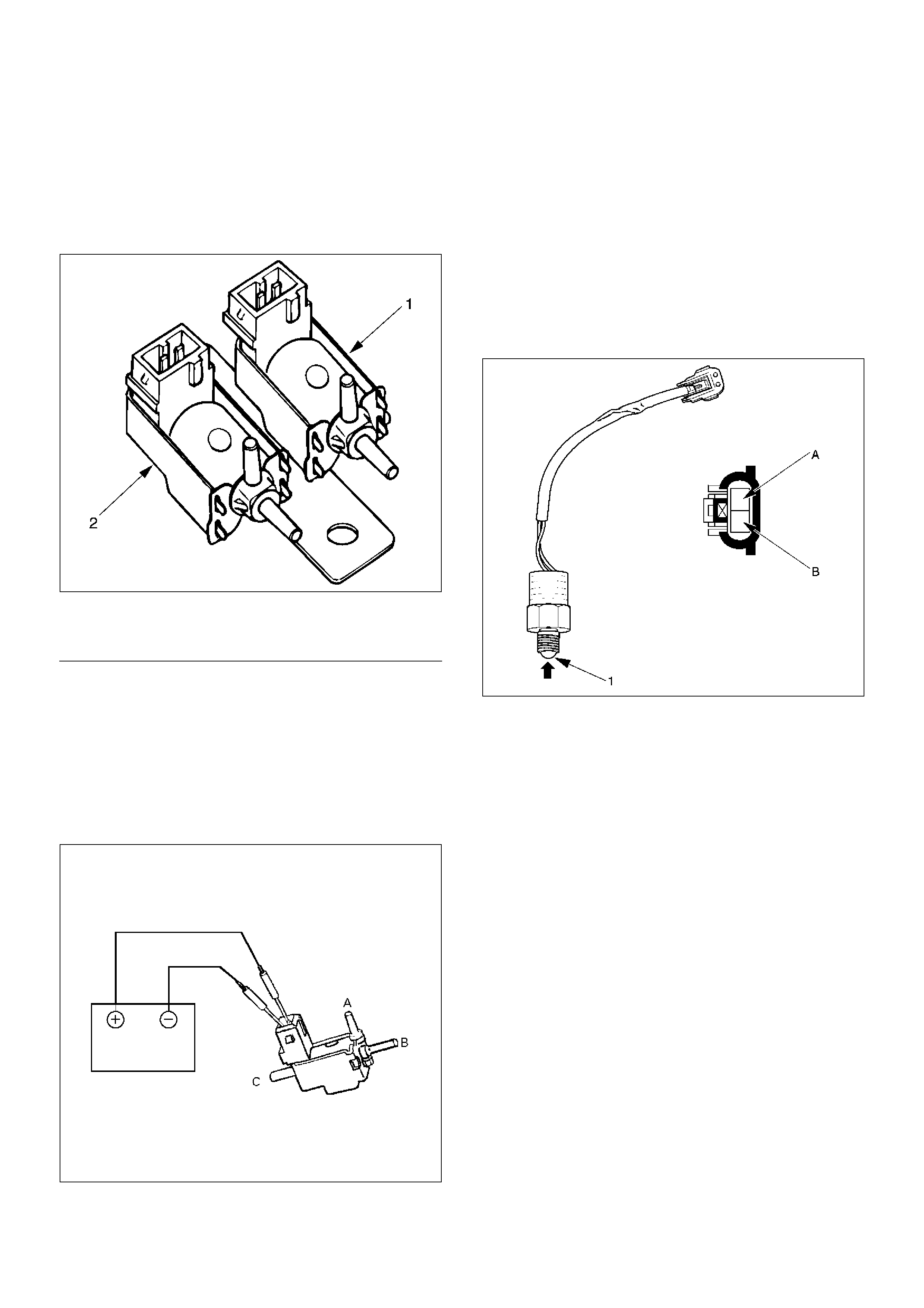
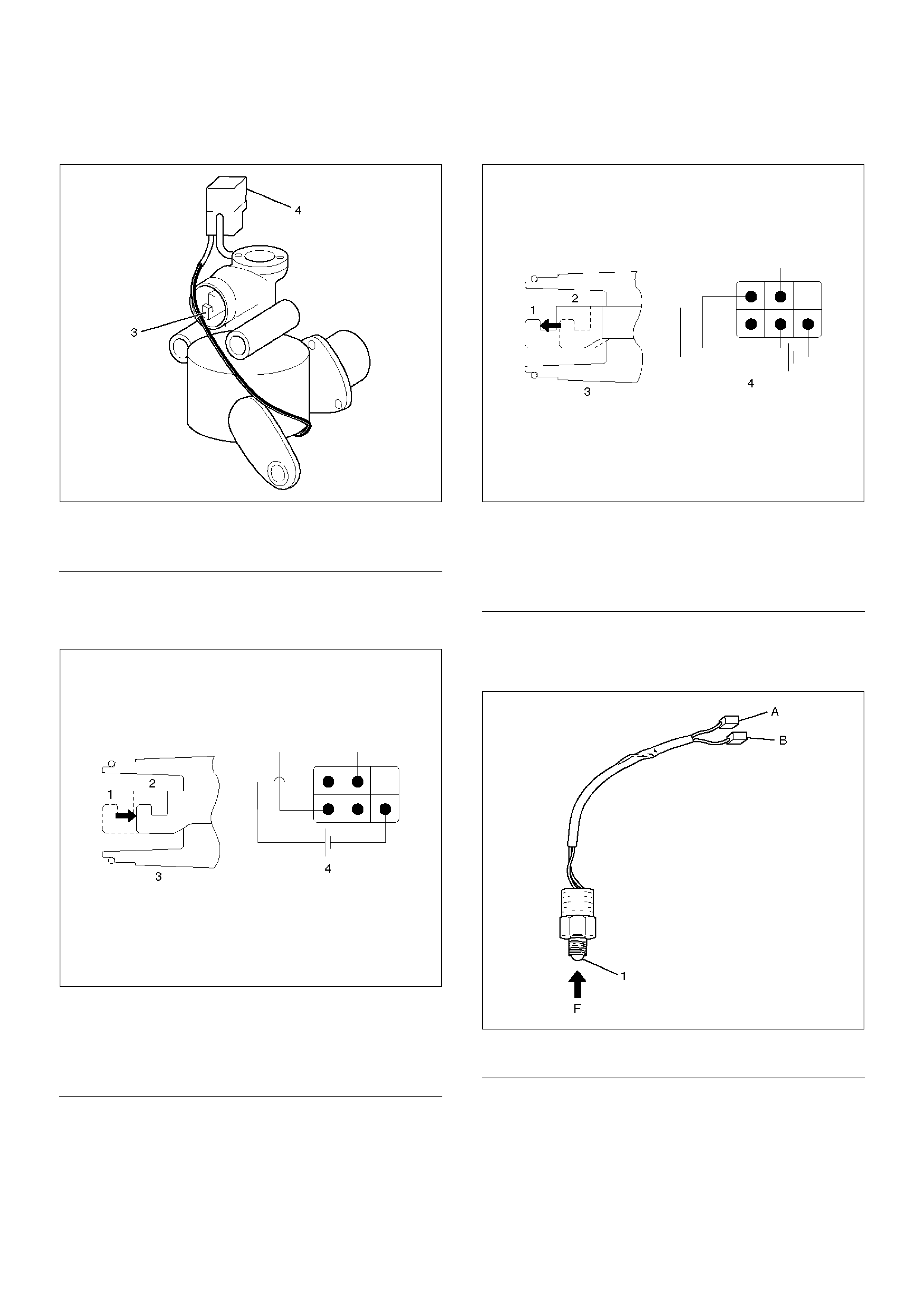
VSV Assembly
Inspect the vehicle side harness as follows:
412RS071
EndOFCallout
1. Remove connector.
2. Shift transfer lever to 2H and start the engine.
NOTE: Do not move the vehicle while inspection.
3. Make sure that there is continuity in the vehicle side
of harness. If there is no continuity, check transfer
shift switch and wiring.
Inspect both VSVs as follows:
F04RS004
1. With battery not connected (Usual).
A–C:There is continuity
B:Closed
2. With battery connected
A – B:There is continuity
C:Closed
3. If 1) and/or 2) fail, replace with a new VSV.
Axle Position Switch
412RS048
1. With ball (1) being free
A – B:There is continuity
2. With ball forced into the switch
A – B:No continuity
3. If 1) and/or 2) fail, replace with a new switch.
Legend
(1) Grey
(2) Blue
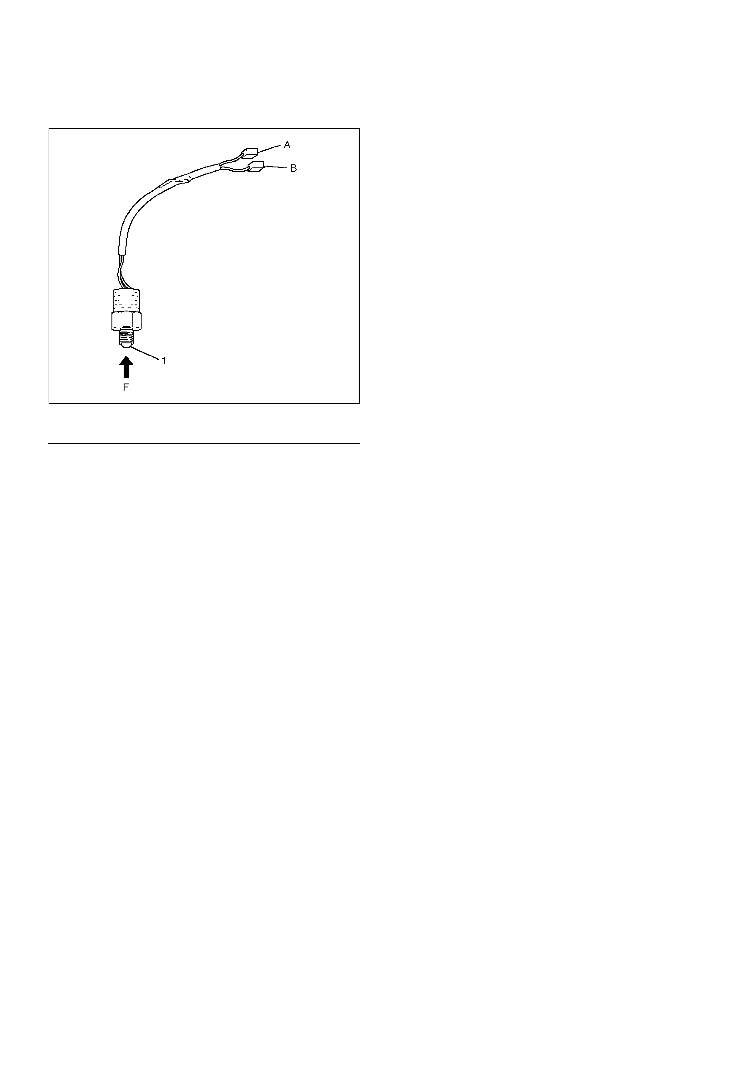
Transfer Position Switch
412RW040
EndOFCallout
1. With ball being free.
A–B : There is continuity.
2. With ball forced into the switch.
A–B : No continuity.
3. If 1) and/or 2) fail, replace with a new switch.
Legend
(1) Ball
Shift on the Fly System (Push Button Type)
Outline of Shift on the Fly System (Push Button Type)
The shift on the fly system switches between 2 wheel
drive (2WD) and 4 wheel drive (4WD) electrically by
driver's pressing the 4WD switch (push button type) on
instrument panel.
This system controls below operations. (Shifting
between “4H” and “4L” must be performed by transfer
control lever on the floor.)
1. Shifting the transfer front output gear (Connecting
to, and disconnecting from, front propeller shaft by
motor actuator).
2. Retrial of shifting the transfer front output gear.
3. Connecting front wheels to, and disconnecting them
from, the front axles by vacuum actuator.
4. Indicator on instrument panel.
5. 4WD out signal to other Electronic Hydraulic Control
Unit (If anti–lock brake system is equipped).
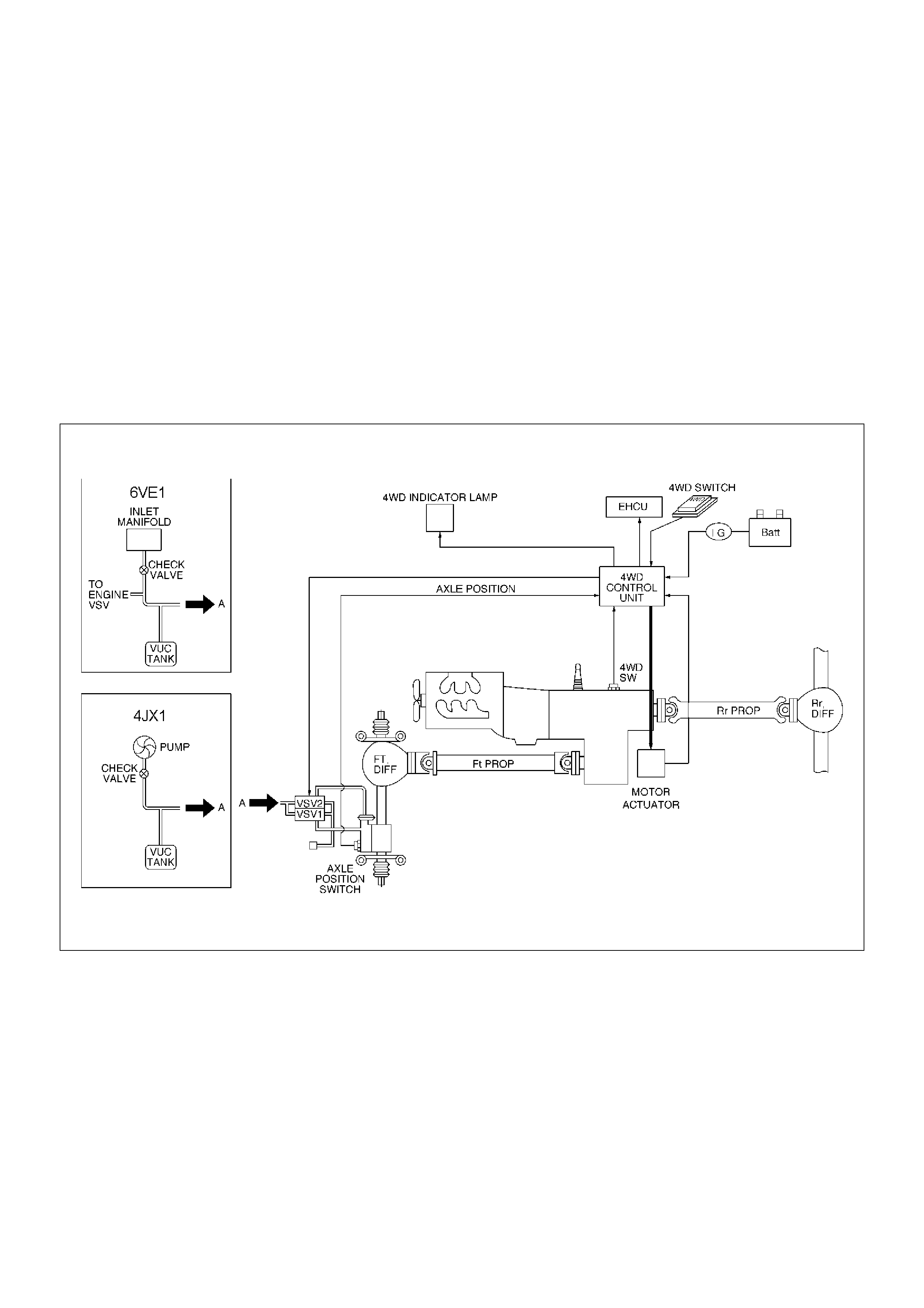
System Diagrams
412RW050
Normal Operation
The motor actuator mounted on transfer rear case is
driven by signal from 4WD switch on instrument panel.
After complete the connecting transfer front output gear
to, or disconnecting it from, front propeller shaft,
condition of the transfer position switch changes. The
vacuum solenoid valve (VSV) is driven by the signal
from transfer position switch and the vacuum actuator
connects front wheels to, or disconnect them from, front
axles.
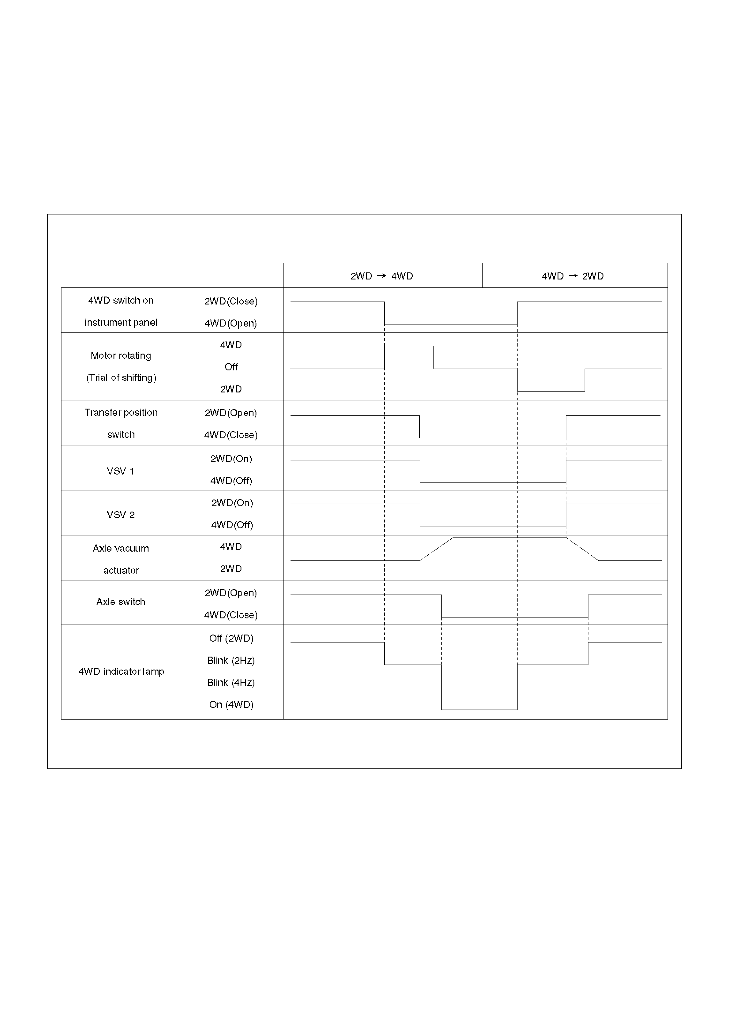
Shift Timing - Normal Operation
F04RW002
Retrial
The transfer motor actuator starts the transfer case gear
moving after a command is received from the 4WD
switch on the instrument panel. However, shifting may
not occur in severe cold weather or under high speed
(>100km/h) conditions. When 2 seconds have passed
since the transfer gear shifting has commenced and the
transfer position switch does not activate (gear
engagement is not completed), the motor reverses its
rotation for 1.2 seconds and automatically repeats the
operation again. If after 3 attempts the transfer position
switch does not activate, the transfer motor actuator will
be disabled and the 4WD indicator lamp will blink 4
times per second to alert the driver that the SOF
operation has failed. The lamp will continue to blink until
the driver selects 2WD mode.
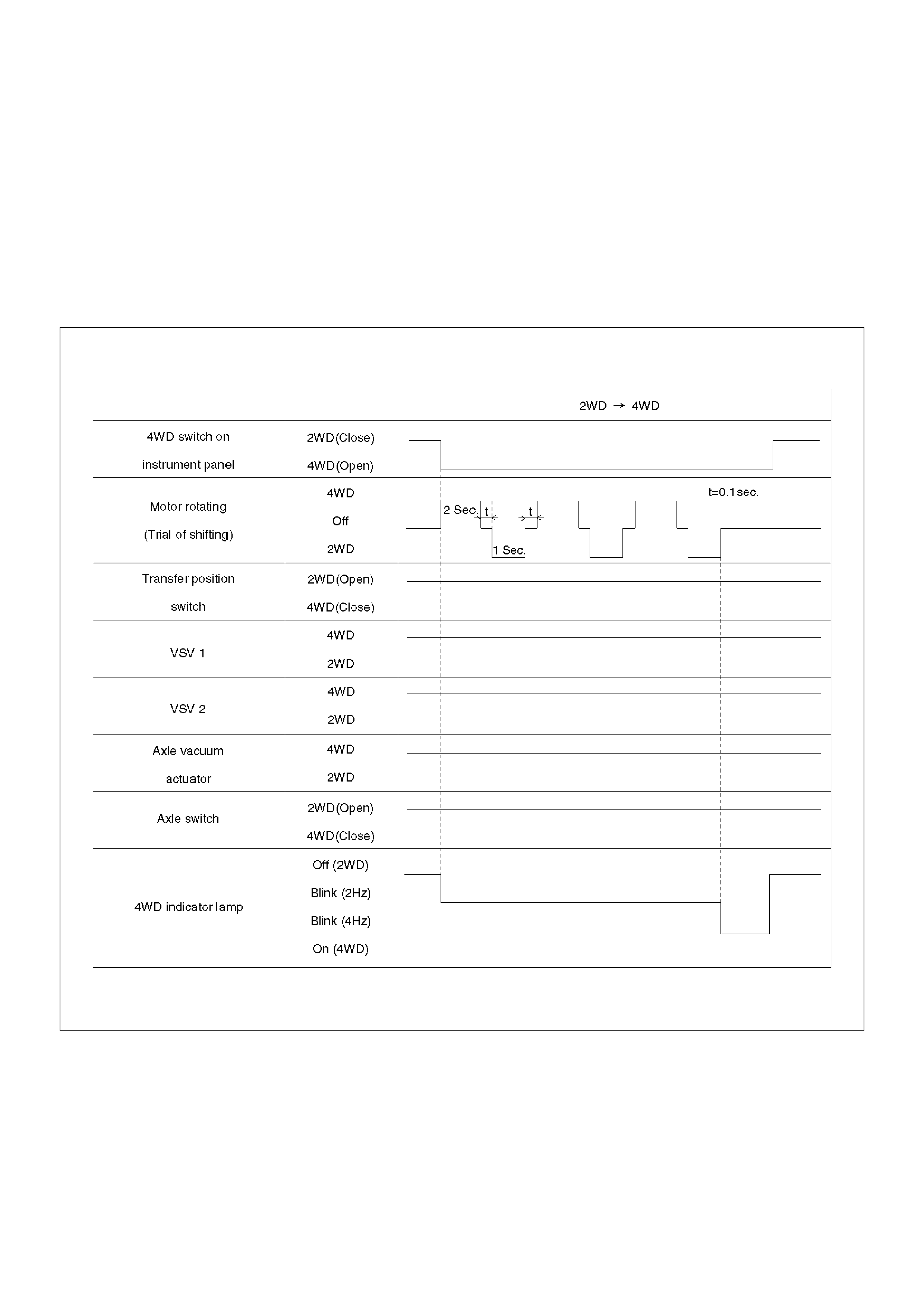
Shift Timing - Under Severe Conditions (retrial)
F04RW003

Warning at “4L" position : Shifting from 4WD to 2WD
while in “4L" mode is not possible. While in “4L" mode,
the transfer position switch cannot be deactivated.
Should the 4WD switch be pressed while in "4L", then
the 4WD indicator lamp will blink 4 times per second to
alert the driver of the incorrect operation and the 4WD
to 2WD mode will be cancelled.
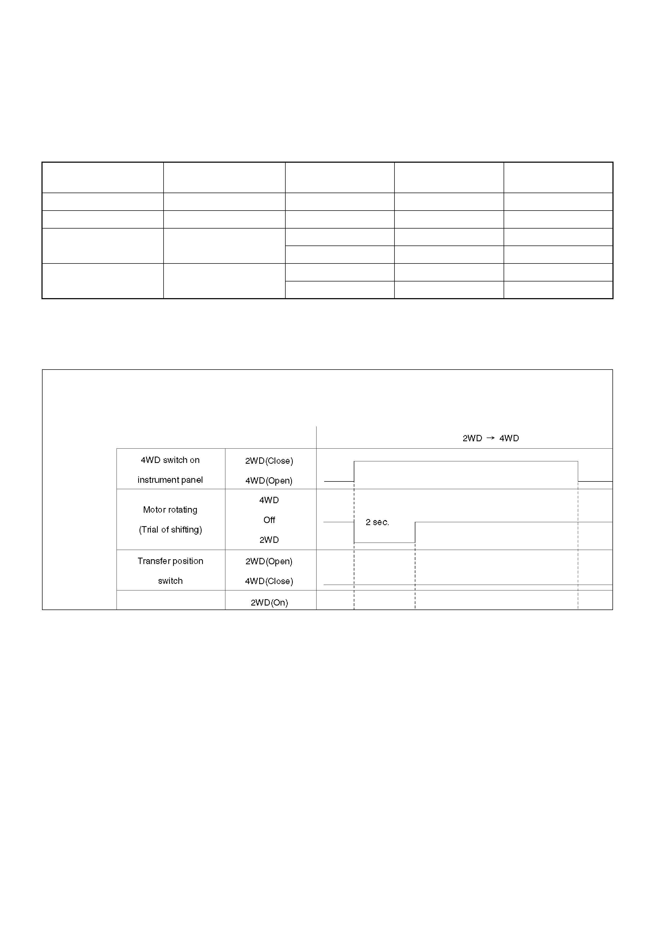
Shift Timing - 4WD to 2WD when in “4L” Mode
F04RW005
4WD out signal to other Electronic Hydraulic
Control Unit : 4WDcontrol unit sends 4WD out signal
to other Electronic Hydraulic Control Unit as below.
4WD out signal
(Period)
Vehicle Condition Transfer position switch Front axle switch
120 ms 2WD 2WD (Open) 2WD (Open)
240 ms 4WD 4WD (Close) 4WD (Close)
4WD Indicator Lamp Function
Indication of vehicle condition :
Indicator lamp is controlled by the Axle Disconnect
Controller and indicates vehicle conditions as below.
Bulb check :The indicator lamp is illuminated for 2
seconds when the ignition is first turned on.
Bulb Check Timing
F04RW004
Retrials from 2WD to 4WD :Shifting from 2WD to 4WD
may not occur when in severe cold weather
conditions or under high speed conditions. Should this
occur, the 4WD indicator lamp will flash continously at a
rate of 4 times per second until the driver disengages
the 4WD operation (see Retrial for more information).
Indicator Vehicle condition 4WD switch Transfer Position
Switch
Front Axle Switch
Off 2WD Off (Close) 2WD (Open) 2WD (Open)
On 4WD On (Open) 4WD (Close) 4WD (Close)
Flash 2 times per
second (2Hz)
Operating On (Open) 4WD (Close) 2WD (Open)
Off (Close) 2WD (Open) 4WD (Close)
Flash 4 times per
second (4Hz)
Shift inoperative On (Open) 2WD (Open) 2WD (Open)
Off (Close) 4WD (Close) 4WD (Close)

Diagnosis
Identifying the problem
When Switching from 2WD to 4WD
1. Flashing of the 4WD indicator changes from 2
times per second (2Hz) , to 4 times per second
(4Hz).
When a high synchronization load is encountered,
the motor actuator will make up to 3 attempts to shift
the transfer gear. The 4WD indicator lamp will flash
at 2Hz while the motor actuator attempts the shift. If
after the 3rd attempt, the shift is not completed, the
4WD indicator lamp will begin to flash at 4Hz and
the motor actuator will return to 2WD mode.
A high synchronization load occurs:
• At severe low temperatures.
• A high rotational difference in speed occurs
between the front wheels and the front axles
during cornering.
Solution 1: Attempt to select 4WD mode again at
a lower speed or when the vehicle is stationary.
2. The 4WD indicator continues flashing at 2Hz for
more than 11.5 seconds.
When there is rotational difference in speed
between the front wheels and axles, the front
wheels and the front axles may have difficulty
engaging. The flashing of the 4WD indicator lamp at
2Hz will indicate that the transfer case is shifting into
the 4WD mode. Shifting into 4WD mode is
impossible if a high rotational difference in speed
occurs between the front wheels and the front axles
during cornering, resulting in the indicator flashing
for an extended period.
Solution 2: If the vehicle is moving, drive the
vehicle straight while accelerating and
decelerating, and if the vehicle is at a stop,
move the vehicle forward and backward for 2 to
3 metres.
When Switching from 4WD to 2WD
1. The 4WD indicator lamp continues to flash 2
times per second.
When switching from 4WD to 2WD, the 4WD
indicator lamp continues to flash until both shifting of
the transfer gear and disconnecting the front wheels
are completed. When drive line is subject to a high
torque load, the shifting transfer gear and
disconnecting of the front wheels are impossible.
In this case, removal of the torque load on the drive
line makes the shifting transfer gear and
disconnecting front wheels possible.
Solution 3: If the vehicle is moving, drive the
vehicle straight while accelerating and
decelerating, and if the vehicle is at a stop,
move the vehicle forward and backward for 2 to
3 metres.
2. When the 4WD indicator lamp flash pattern changes
from 2Hz to 4Hz.
Check the position of the transfer lever. Is it in the
“4L" position? Shifting from 4WD to 2WD while at
“4L" will not occur.
Solution 4: Push the 4WD switch ON (to 4WD),
then shift the transfer lever to the “High"
position and then push the 4WD switch OFF (to
engage to 2WD).
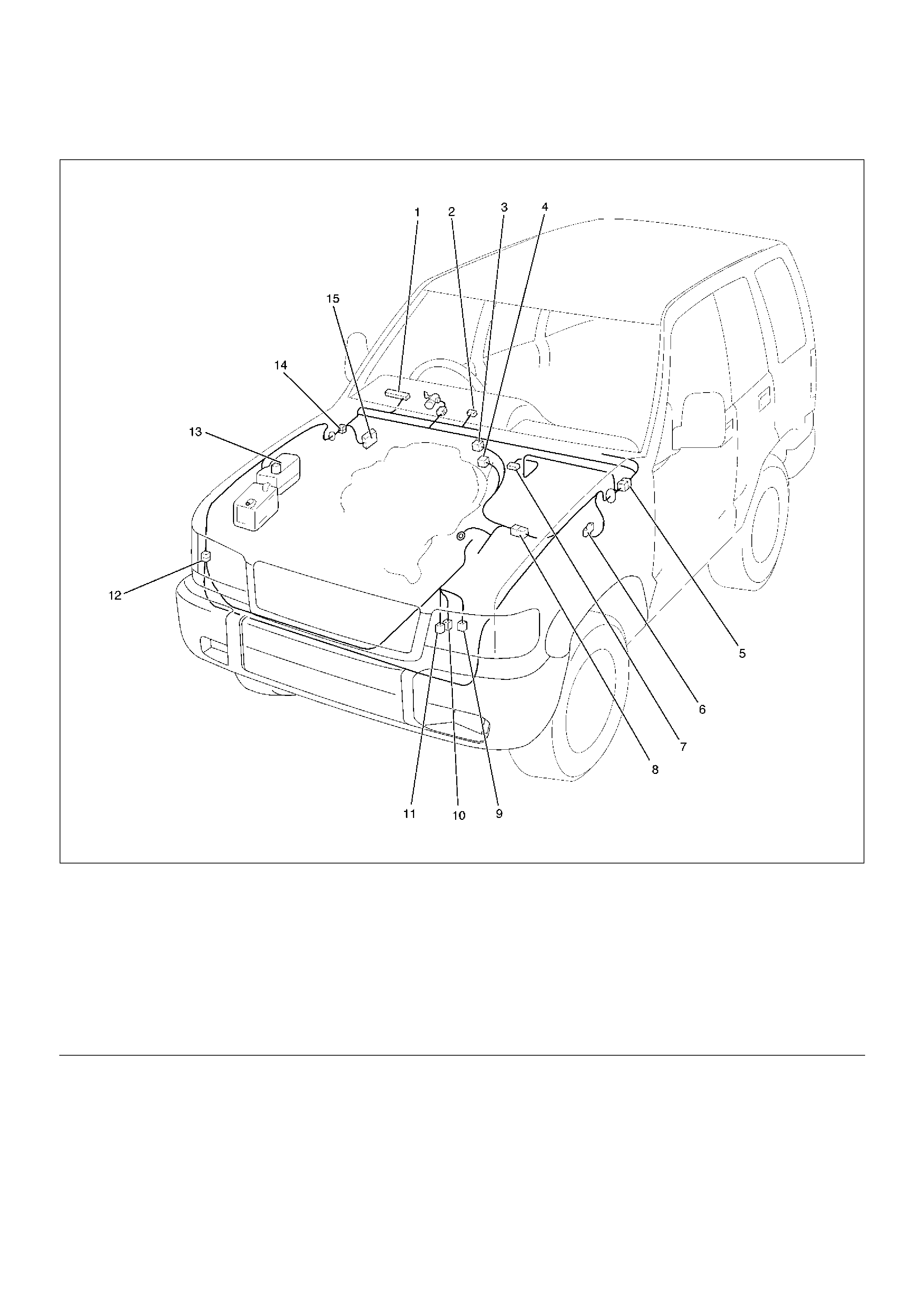
Parts Location (4JX1 DIESEL)
D08RW831
EndOFCallout
Legend
(1) I–9
(2) I–12
(3) E–45
(4) E–21
(5) H–7, H–9
(6) C–16
(7) C–94
(8) H–4, H–5
(9) P–17
(10) P–18
(11) P–19
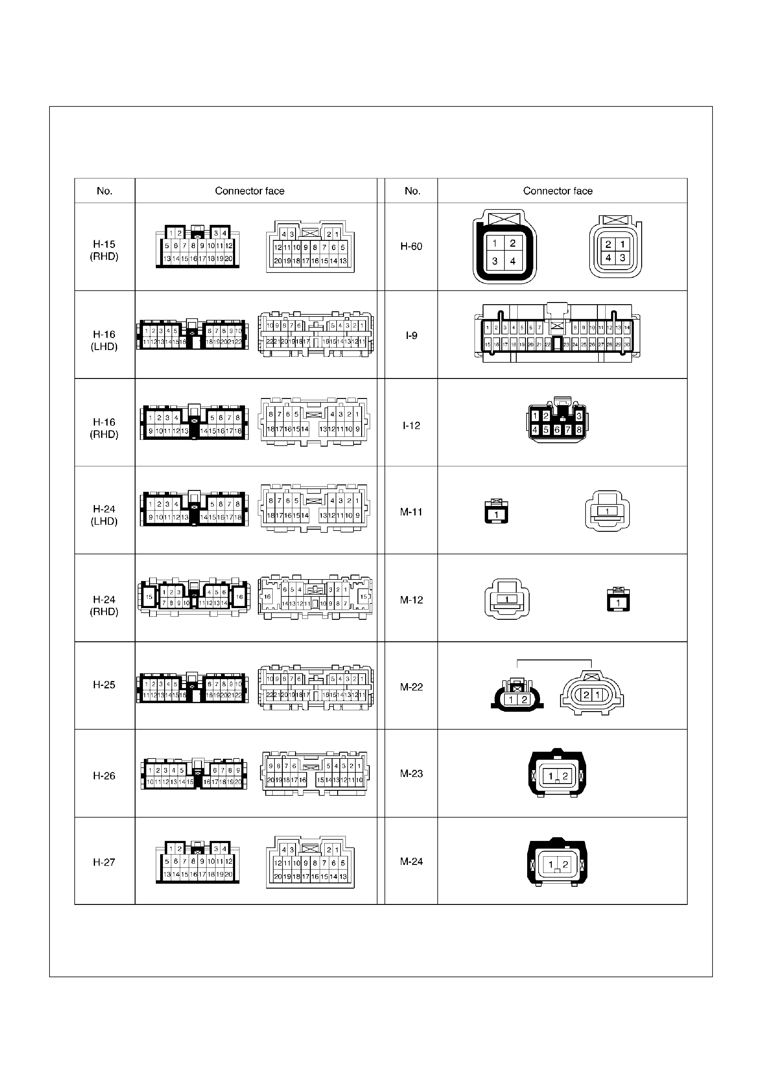
(12) H–60
(13) Relay & Fuse Box
(14) H–15, H–16, H–25, H–26, H–27
(15) Fuse Box
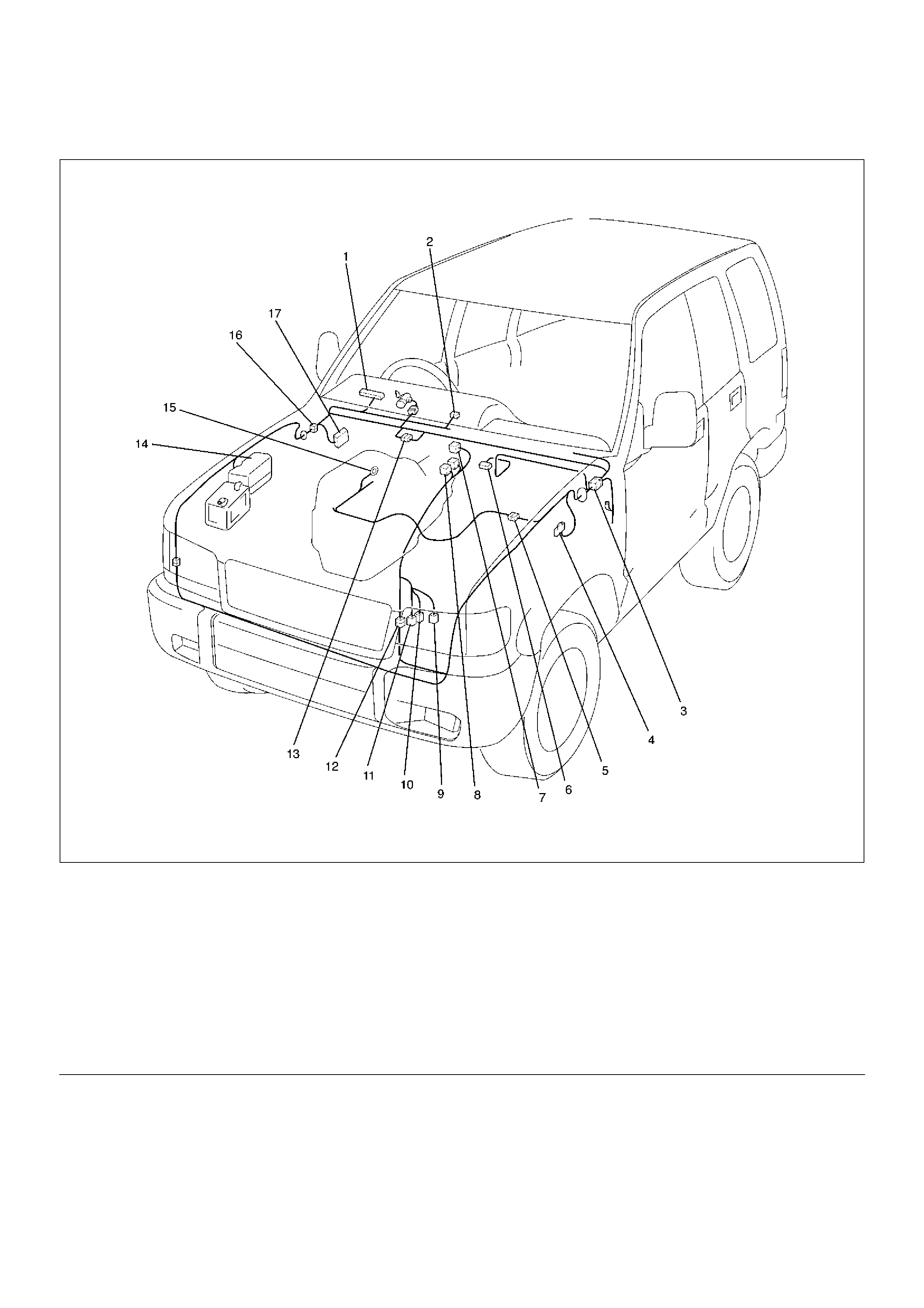
Parts Location (6VE1 PETROL)
D08RW853
EndOFCallout
Legend
(1) I–9
(2) I–12
(3) H–7, H–9
(4) C–16
(5) H–5
(6) C–94
(7) M–26
(8) M–11, M–12
(9) M–22
(10) M–23
(11) M–24
(12) H–10
(13) H–12
(14) Relay & Fuse Box
(15) E–30
(16) H–15, H–16, H–25, H–26, H–27
(17) Fuse Box
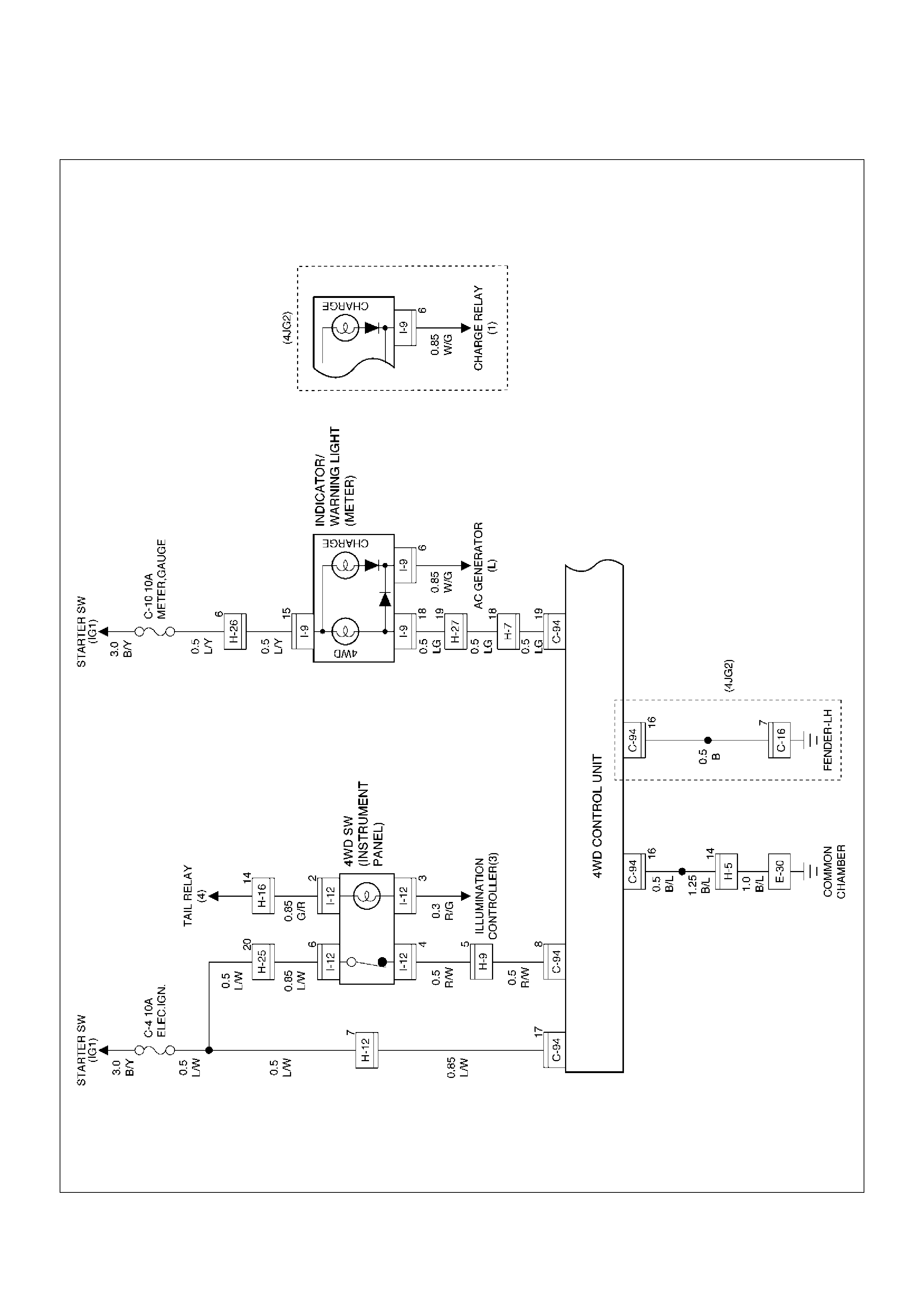
Wiring Diagram
D08RW844

Wiring Diagram (4JX1 DIESEL)
D08RW842
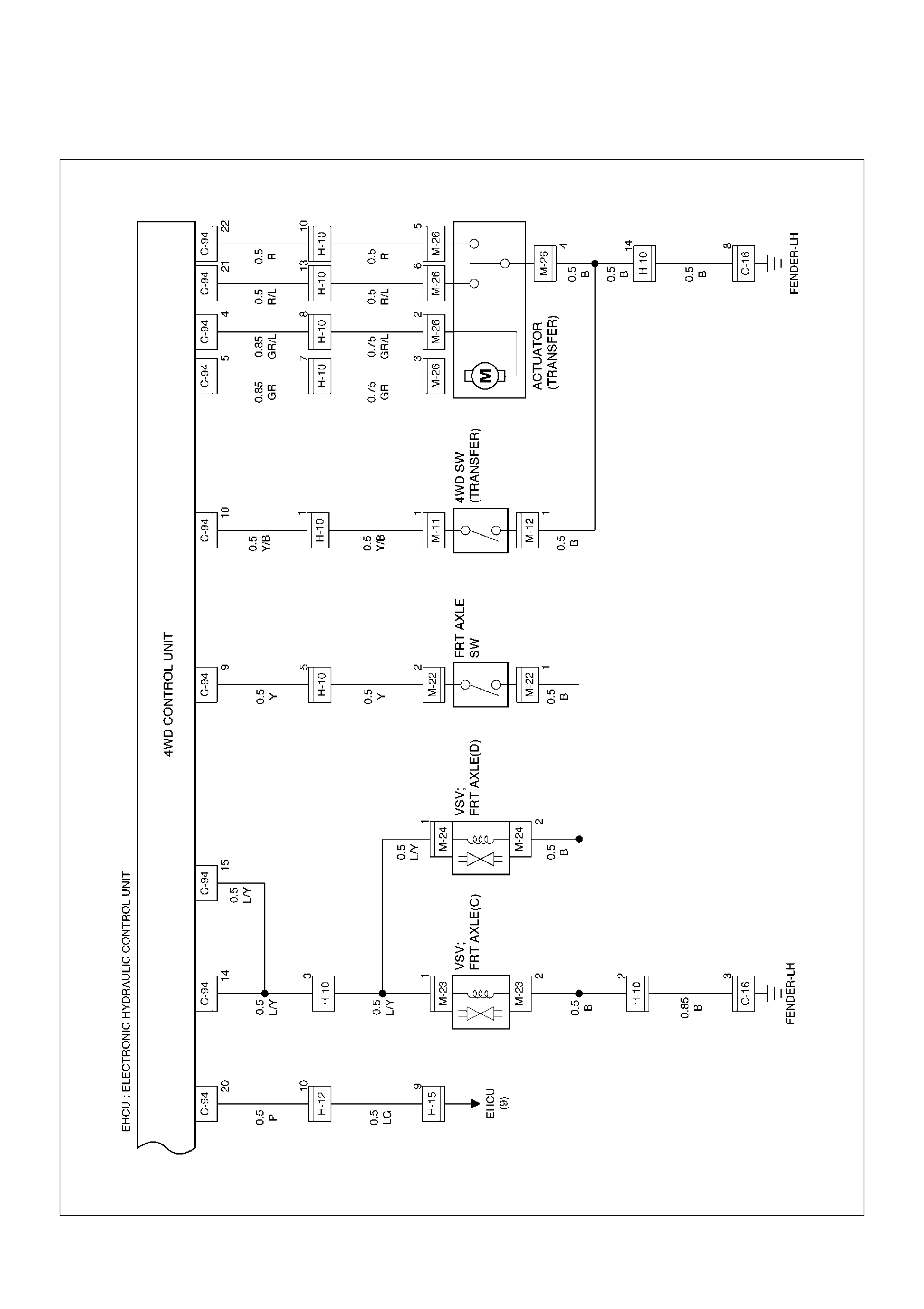
Wiring Diagram (6VE1 PETROL)
D08RW638
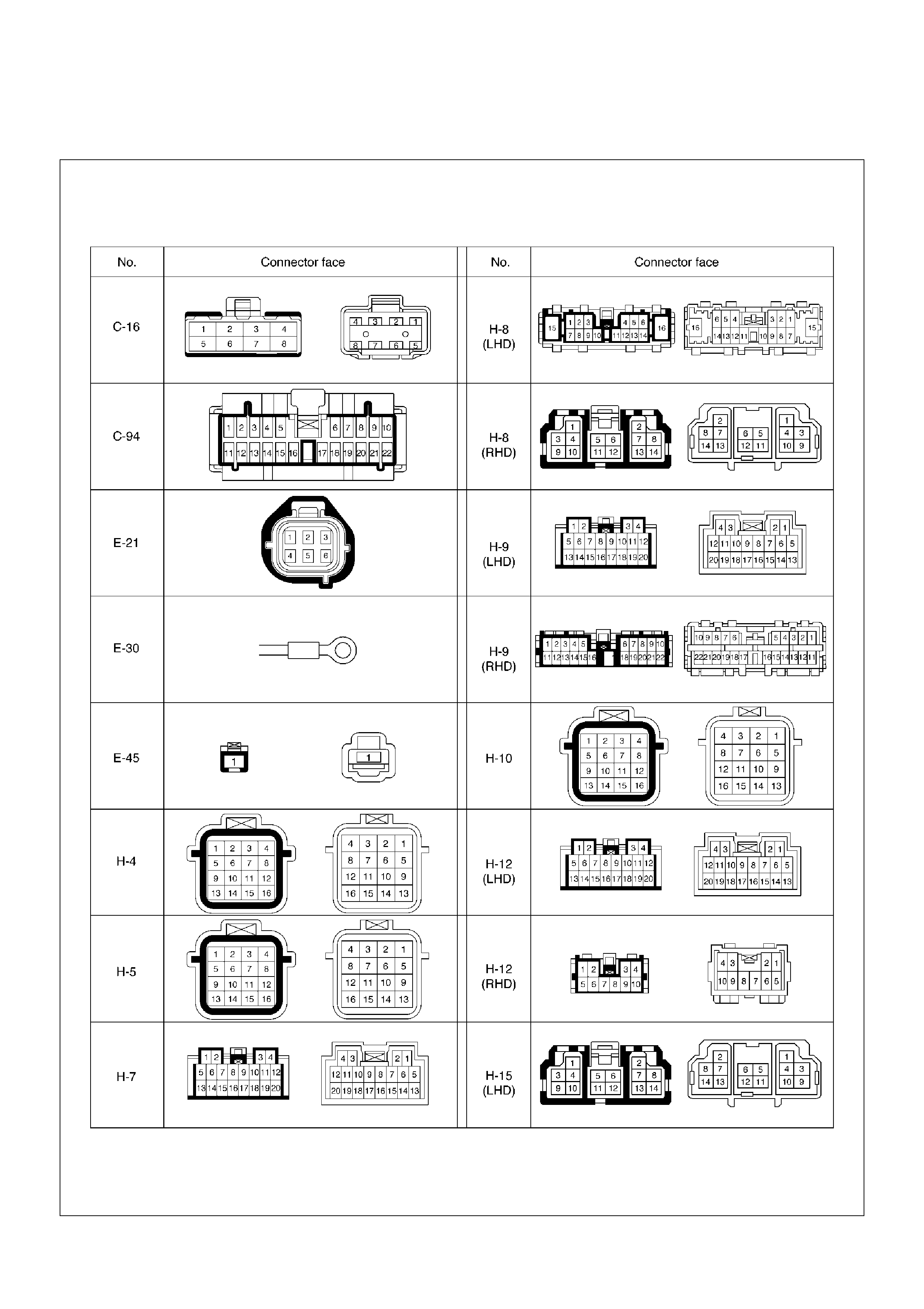
Connector List

Fault diagnosis based on the status of 4WD Indicator Lamp, 4WD Switch and T/F Change
Lever
A diagnostic flow chart is shown below. If after performing the diagnosis and a condition still exists, then there may be
a fault in the Axle Disconnect Controller. The Axle Disconnect Controller will need to be replaced and perform the
diagnostic flow chart again.
Fault on Switching from 2WD to 4WD
1. When the 4WD indicator lamp flash pattern changes from 2Hz to 4Hz after performing “Solution 1."
The motor actuator or the transfer case assembly may be inoperative. Remove and bench test the motor actuator.
Make any necessary repairs and perform “Solution 1" again. Then disassemble and inspect the transfer case
assembly. Repair or replace as needed. If after the repairs, the condition still exists, then replace the 4WD Control
Unit.
2. When the 4WD indicator lamp does not flash or light up when switching from 2WD to 4WD.
Step Action Yes No
1
Is ignition turned on?
Go to 5JAF
Turn on the ignition
and trace this chart
from start.
2
Does the 4WD indicator lamp light up during the two second
initialization after the ignition is turned on?
Go to 5JAF!
Failed indicator
lamp or
disconnected
harness wire.
Perform the
diagnostic chart
from step 1 after
repair or
replacement.
3
Is the 4WD switch activated from 2WD to 4WD mode?
Short-circuit
(body short) on
harness of the
4WD switch.
Inoperative
4WD switch
(stuck closed
condition).
Trace this chart
from the step 1
after repair or
replace.
Push the 4WD
switch to 4WD.

3. When the 4WD Indicator lamp continues to flash after performing Solution 2.
Step Action Yes No
1 Check the air pressure and wear of all tyres.
Were problems found?
Try Solution 2
after adjust the air
pressure and
replace worn tyres. Go to Step 2
2
Can the transfer lever be operated from High to 4L or vice versa?
Go to Step 3
Disconnection
of the motor
actuator
harness wiring.
Trace this chart
from the start
after repair or
replace.
Faults on the
motor actuator.
Trace this chart
from the start
after replace.
Internal faults of
transfer case.
Disassemble
the transfer
case for check.
Trace this chart
from the start
after repair or
replace.
3 Pull out the hoses from vacuum actuator and operate 4WD
switch.
Is there negative pressure on either of hoses?
Go to Step 4
Faults on the
transfer position
switch or its
harness. Trace
this chart from
the start after
repair or
replace.
Faults on the
VSV main body,
its harness or
vacuuming
system. Trace
the front axle
diagnosis chart
in this section.
After that, trace
this chart from
the start.
4 Check the axle switch.
Were problems found?
Internal faults on
axle switch. Trace
this chart from the
start after replace.
Disconnection
on the axle
harness. Trace
this chart from
the start after
repair or
replace.
Faults on Front
Axle ASM.
Trace the front
axle diagnosis
chart in this
section. After
that, trace this
chart from the
start.

Fault on Switching from 4WD to 2WD
1. Indicator lamp on continuously.
Step Action Yes No
1
Does the indicator lamp turn off at ignition off? Go to 5JAF
Short circuit of the
indicator harness.
2
Is the 4WD switch on 2WD position?
Open circuit in the
4WD switch
harness or
breakdown of the
4WD switch in
open state. Trace
this chart from the
start after repair or
replace.
Turn the 4WD
switch to 2WD
position. Trace this
chart from the
start.

2. When the indicator lamp continues to flash at 2Hz after performing Solution 3.
Step Action Yes No
1 Check the air pressure and wear of all tyres.
Were problems found?
Try Solution 3
after adjust the air
pressure and
replace worn tyres. Go to Step 2
2
Can the transfer lever be operated from High to 4L or vice versa?
Faults on the
harness wiring
of motor
actuator. Trace
this chart from
the start after
repair or
replace.
Internal faults
on transfer
case.
Disassemble
the transfer
case for check.
Trace this chart
from the start
after repair or
replace.
Faults on the
motor actuator.
Trace this chart
from the start
after or replace. Go to Step 3
3 Pull out the hoses from vacuum actuator and operate 4WD
switch.
Is there negative pressure on either of hoses?
Go to Step 4
Faults on the
transfer position
switch or its
harness. Trace
this chart from
the start after
repair or
replace.
Faults on the
VSV main body,
its harness or
vacuuming
system. Trace
the front axle
diagnosis chart
in this section.
After that, trace
this chart from
the start.
4 Check the axle switch.
Were problems found?
Internal faults
on axle switch.
Trace this chart
from the start
after replace.
Faults on Front
Axle ASM.
Trace the front
axle diagnosis
chart in this
section. After
that, trace this
chart from the
start.
Short circuit (body
short) or
disconnection of
the axle harness.
Trace this chart
from the start after
repair or replace.

3. Indicator flash changes to 4Hz after Solution 4 is carried out.
Step Action Yes No
1
Can the transfer lever be operated from High to 4L or vice versa?
Faults on the
harness wiring
of motor
actuator. Trace
this chart from
the start after
repair or
replace.
Faults on the
motor actuator.
Trace this chart
from the start
after replace.
Internal faults
on transfer
case.
Disassemble
the transfer
case for check.
Trace this chart
from the start
after repair or
replace.
Faults on the 4WD
control unit. Trace
this chart from the
start after replace.

Front Axle Diagnosis
• When the 4WD switch is operated from 4H to 2H,
indicator light does not go out.
Step Action Yes No
1 1. Allow the engine to idle
2. Drive slowly forward for 100 — 200m.
Has the 4WD indicator light gone out?
System functioning
correctly. Go to Step 2
2 1. Jack up front wheels and support vehicle with safety stands.
2. Rotate the passenger side front wheel by hand.
Does the drver side wheel rotate? Go to Step 4 Go to Step 3
3 1. Check the actuator switch.
2. Check the circuit to indicator.
Was a problem found?
Trace this chart
from the start after
component repair
or replacement.
Disassemble axle
assy. for check.
Trace this chart
from the start after
component repair
or replacement.
4 1. Check the VSV valve.
2. Check the circuit to VSV valve.
Was a problem found?
Trace this chart
from the start after
component repair
or replacement. Go to Step 5
5 Is vacuum circuit OK? (tank, hose, or pipe damaged)
Go to Step 6
Trace this chart
from the start after
component repair
or replacement.
6 Does the actuator operate correctly?
Trace this chart
from the start.
Disassemble axle
assy. for check.
Trace this chart
from the start after
component repair
or replacement.

• When the 4WD switch is operated from 2H to 4H,
indicator light is not actuated.
Step Action Yes No
1 1. Allow the engine to idle
2. Drive slowly forward for 100 — 200m.
Has the 4WD indicator light gone out?
System functioning
correctly. Go to Step 2
2 1. Jack up front wheels and support vehicle with safety stands.
2. Rotate the passenger side front wheel by hand.
Does the drver side wheel rotate? Go to Step 4 Go to Step 3
3 1. Check the actuator switch.
2. Check the circuit to indicator.
Was a problem found?
Trace this chart
from the start after
component repair
or replacement.
Disassemble axle
assy. for check.
Trace this chart
from the start after
component repair
or replacement.
4 1. Check the VSV valve.
2. Check the circuit to VSV valve.
Was a problem found?
Trace this chart
from the start after
component repair
or replacement. Go to Step 5
5 Is vacuum circuit OK? (tank, hose, or pipe damaged)
Go to Step 6
Trace this chart
from the start after
component repair
or replacement.
6 Does the actuator operate correctly?
Trace this chart
from the start.
Disassemble axle
assy. for check.
Trace this chart
from the start after
component repair
or replacement.
Shift on the Fly Vacuum Hoses and Electric Equipment
(Push Button Type)
Vacuum Hose Routing Diagram
C04RW013
VSV Assembly, Actuator Assembly
412RS032
Vacuum Tank
412RS033
Inspection and Repair
Vacuum Hoses
C04RW014
1. Pull out the Hose A in figure and install a vacuum
gauge.
2. Plug up Hose B in figure to prevent the leak of
vacuum.
3. Start the engine and measure vacuum 2 or 3
minutes afterward.
4. Repeat 1) and 2) but with Hose A plugged and Hose
B pulled out.
5. If vacuum measures –400mmHg, or if it shows a
sudden drop immediately after engine stop, inspect
the hose, tank, and pipe for damage.
NOTE: Be careful not to permit the entry of dust and
water during inspection.
6. Pull out Hose D in above illustration.
7. Plug Hose E in above illustration.
8. Make sure that Hose D in above illustration is under
atmospheric pressure.
9. Pull out Hose E and plug Hose D, and make sure
that Hose E is under atmospheric pressure.
10. If Check 8) or 9) has revealed stoppage, check and
see that there is no bend, foreign matter in the hose
or in the filter. If there is trouble, repair or replace.
Check Valve
C04RS004
1. Apply vacuum from the orange colored side(1).
Vacuum:–400mmHg
2. Check leakage of vacuum.
3. Make sure that vacuum cannot be applied from the
black colored side(2).

4. If vacuum is not applicable as much as –400mmHg,
and if there is resistance on the intake side, replace
with a new check valve.
VSV Assembly
Inspect the vehicle side harness as follows:
412RS071
EndOFCallout
1. Remove connector.
2. Shift transfer lever to 2H and start the engine.
NOTE: Do not move the vehicle while inspection.
3. Make sure that there is continuity in the vehicle side
of harness. If there is no continuity, check transfer
shift switch and wiring.
Inspect both VSVs as follows:
F04RS004
1. With battery not connected (Usual).
A–C:There is continuity
B:Closed
2. With battery connected
A – B:There is continuity
C:Closed
3. If 1) and 2) fail, replace with a new VSV.
Axle Position Switch
412RS048
1. With ball (1) being free
A – B:There is continuity
2. With ball forced into the switch
A – B:No continuity
3. If 1) and 2) fail, replace with a new switch.
Motor Actuator Assembly
Inspect the function of the motor actuator assembly as
follows:
Legend
(1) Grey
(2) Blue
1. Disassemble the motor actuator from transfer rear
case.
412RW037
EndOFCallout
2. Connect the terminals as shown in figure.
Shift rod of the motor actuator moves and stops
at 4WD position.
412RW038
EndOFCallout
3. Connect the terminals as shown in figure.
Shift rod of the motor actuator moves and stops
at 2WD position.
412RW039
EndOFCallout
4. If 2) and 3) fail, replace with a new motor actuator.
Transfer Position Switch
412RW040
EndOFCallout
1. With ball being free.
A–B : There is continuity.
2. With ball forced into the switch.
A–B : No continuity.
3. If 1) and 2) fail, replace with a new switch.
Legend
(3) Shift Rod
(4) Connector
Legend
(1) 2WD
(2) 4WD
(3) Shift Rod
(4) Connector
Legend
(1) 2WD
(2) 4WD
(3) Shift Rod
(4) Connector
Legend
(1) Ball
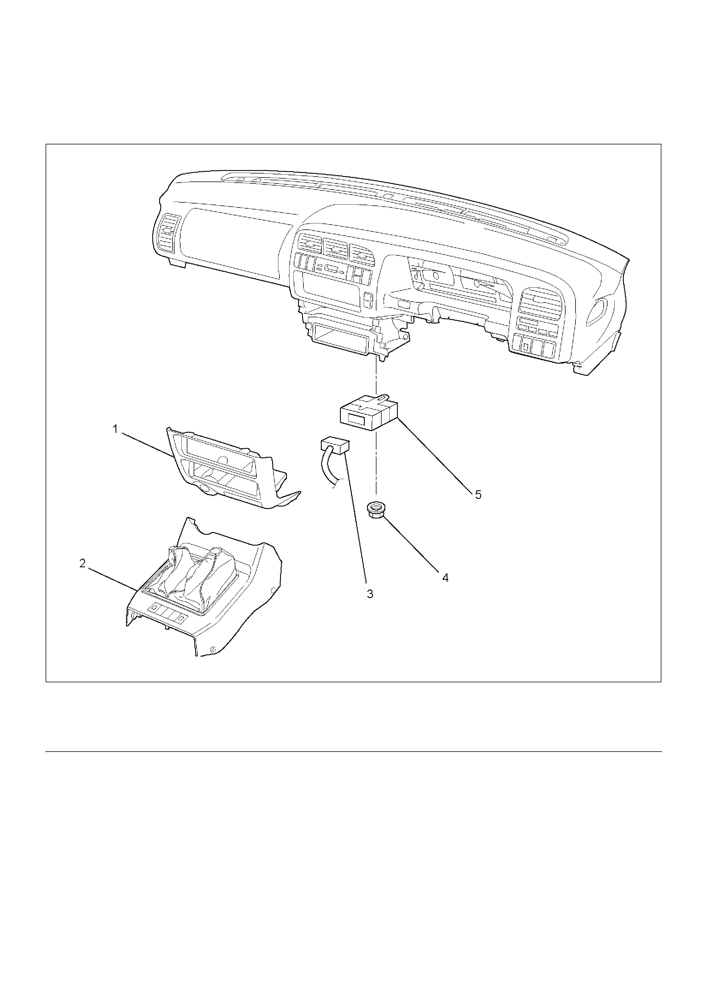
4WD Control Unit (For Push Button Type)
4WD Control Unit Associated Parts
412RW044
EndOFCallout
Legend
(1) Lower Cluster Assembly
(2) Front Console Assembly
(3) Harness Connector
(4) Nut
(5) 4WD Control Unit
Removal
1.Remove lower cluster assembly and front console
assembly.
Refer to Interior Trim in Body and Accessories
section.
2. Remove nut.
3. Remove 4WD control unit.
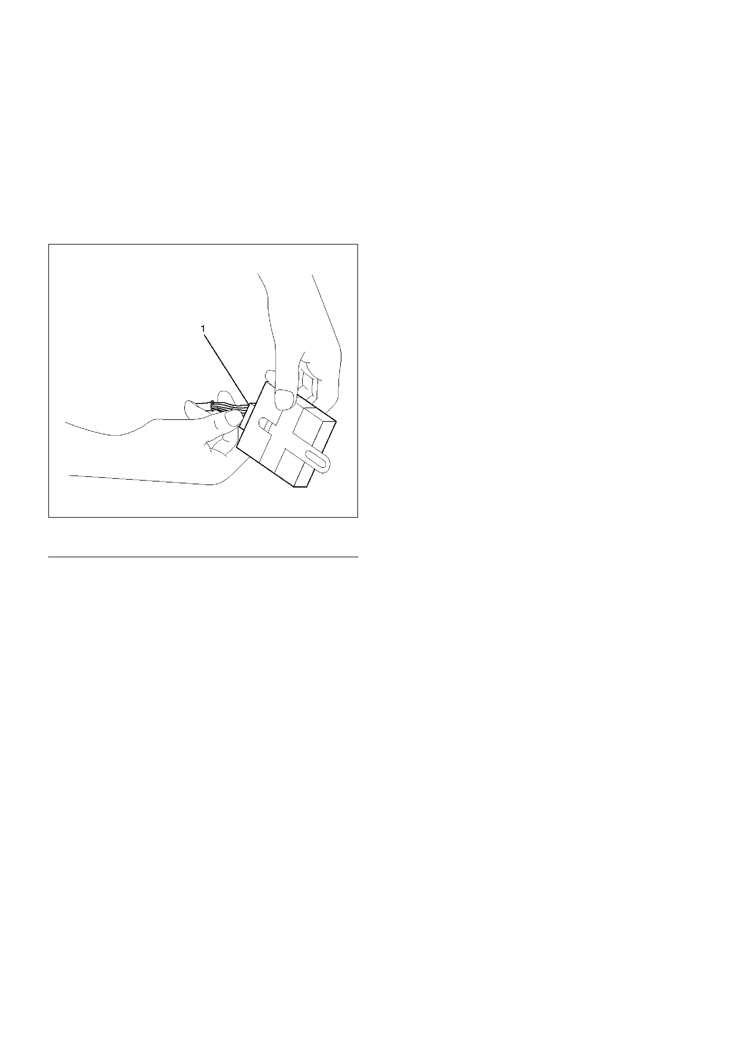
4. Disconnect harness connector (1).
412RW045
EndOFCallout
Installation
1. Connect harness connector, then install 4WD
control unit.
2. Install lower cluster assembly and front console
assembly.
Legend
(1) Harness Connector