
SECTION 4B - FRONT AXLE & DIFFERENTIAL
Service Precaution
Front Drive Axle
Diagnosis
Pinion Shaft Oil Seal
Pinion Shaft Oil Seal and Associated Parts
Removal
Inspection and Repair
Installation
Front Drive Axle Assembly
Front Drive Axle Assembly and Associated Parts
Removal
Installation
Differential Assembly
Disassembled View
Disassembly
Reassembly
Differential Cage Assembly
Disassembled View
Disassembly
Inspection and Repair
Reassembly
Main Data and Specifications
General Specifications
Torque Specifications
Special Tools
Service Precaution
WARNING: IF SO EQUIPPED WITH A
SUPPLEMENTAL RESTRAINT SYSTEM (SRS),
REFER TO THE SRS COMPONENT AND WIRING
LOCATION VIEW IN ORDER TO DETERMINE
WHETHER YOU ARE PERFORMING SERVICE ON
OR NEAR THE SRS COMPONENTS OR THE SRS
WIRING. WHEN YOU ARE REFORMING SERVICE
ON OR NEAR THE SRS COMPONENTS OR THE SRS
WIRING, REFER TO THE SRS SERVICE
INFORMATION. FAILURE TO FOLLOW WARNINGS
COULD RESULT IN POSSIBLE AIR BAG
DEPLOYMENT, PERSONAL INJURY, OR
OTHERWISE UNNEEDED SRS SYSTEM REPAIRS.
CAUTION: Always use the correct fastener in the
proper location. When you replace a fastener, use
ONLY the exact part number for that application.
HOLDEN will call out those fasteners that require a
replacement after removal. HOLDEN will also call
out the fasteners that require thread lockers or
thread sealant. UNLESS OTHERWISE SPECIFIED ,
do not use supplemental coatings (Paints, greases,
or other corrosion inhibitors) on threaded fasteners
or fastener joint interfaces. Generally, such
coatings adversely affect the fastener torque and
the joint clamping force, and may damage the
fastener. When you install fasteners, use the
correct tightening sequence and specification.
Following these instructions can help you avoid
damage to parts and systems.
Techline

Front Drive Axle
Diagnosis
Condition Possible Cause Correction
Oil Leak At Front Axle Worn or defective oil seal. Replace the oil seal.
Front axle housing cracked. Repair or replace.
Oil Leak At Pinion Shaft Too much gear oil. Correct the oil level.
Oil seal worn or defective. Replace the oil seal.
Pinion flange loose or damaged. Tighten or replace.
Noises In Front Axle Drive Shaft
Joint
Broken or worn drive shaft joints and
bellows (BJ and DOJ).
Replace the drive shaft joints and
bellows.
“Clank”When Accelerating From
“Coast”
Loose drive shaft joint to output shaft
bolts.
Tighten.
Damaged inner drive shaft joint. Replace.
Shudder or Vibration During
Acceleration
Excessive drive shaft joint angle. Repair.
Worn or damaged drive shaft joints. Replace.
Sticking spider assembly (inner drive
shaft joint).
Lubricate or replace.
Sticking joint assembly (outer drive
shaft joint).
Lubricate or replace.
Vibration At Highway Speeds Out of balance or out of round tires. Balance or replace.
Front end out of alignment. Align.
Noises in Front Axle Insufficient gear oil. Replenish the gear oil.
Wrong or poor grade gear oil. Replace the gear oil.
Drive pinion to ring gear backlash
incorrect.
Adjust the backlash.
Worn or chipped ring gear, pinion
gear or side gear.
Replace the ring gear, pinion gear or
side gear.
Pinion shaft bearing worn. Replace the pinion shaft bearing.
Wheel bearing worn. Replace the wheel bearing.
Differential bearing loose or worn. Tighten or replace.
Wanders and Pulls Wheel bearing preload too tight. Adjust the wheel bearing preload.
Incorrect front alignment. Adjust the front alignment.
Steering linkage loose or worn. Tighten or replace.
Steering gear out of adjustment. Adjust or replace the steering gear.
Tire worn or improperly inflated. Adjust the inflation or replace.
Front or rear suspension parts loose
or broken.
Tighten or replace.

Front Wheel Shimmy Wheel bearing worn or improperly
adjusted.
Adjust or replace.
Incorrect front alignment. Adjust the front alignment.
Worn ball joint or bush. Replace the ball joint or bush.
Steering linkage loose or worn. Tighten or replace.
Steering gear out of adjustment. Tighten or replace.
Tire worn or improperly inflated. Replace or adjust the inflation.
Shock absorber worn. Replace the shock absorber.
Condition Possible Cause Correction
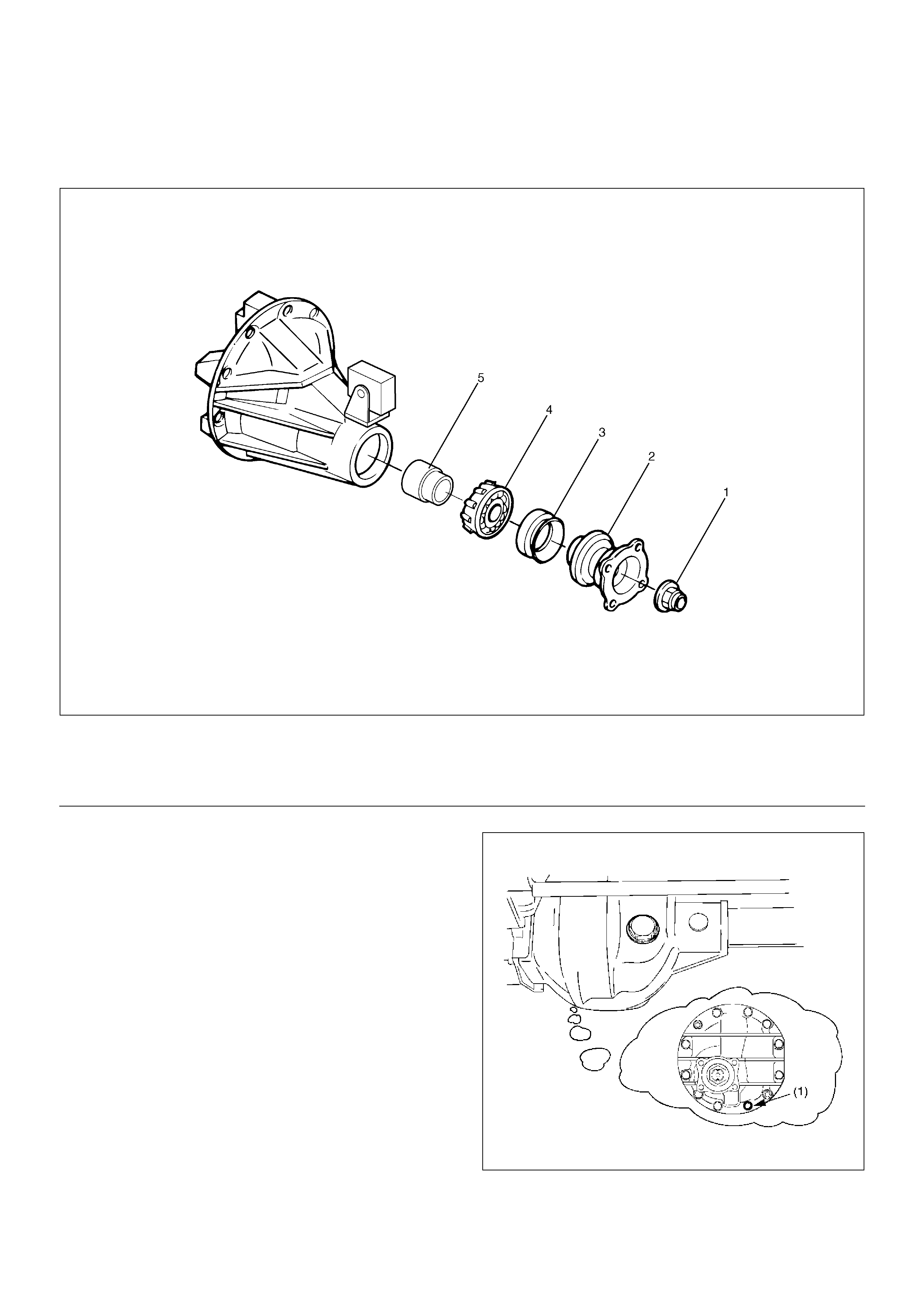
Pinion Shaft Oil Seal
Pinion Shaft Oil Seal and Associated Parts
415RW015
EndOFCallout
Removal
1. Raise the vehicle and support it at the frame.
The hoist must remain under the front axle housing.
2. Drain the front axle oil by loosening the drain
plug(1).
412RS001
Legend
(1) Flange Nut
(2) Flange
(3) Oil Seal
(4) Outer Bearing
(5) Collapsible Spacer
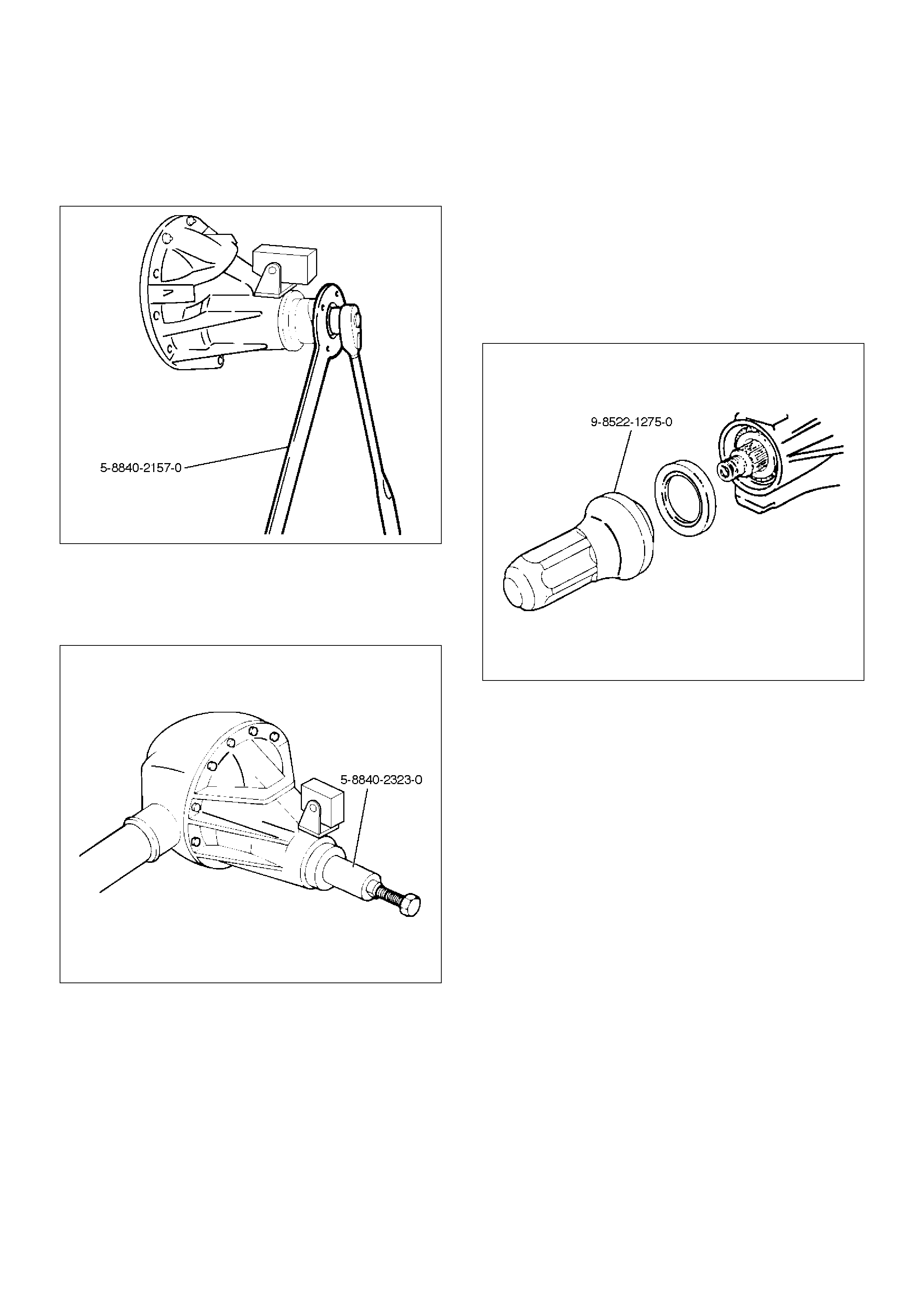
3.Remove the front propeller shaft. Refer to Front
Propeller Shaft in this section.
4.Remove flange nut by using pinion flange holder 5–
8840–2157–0.
425RW045
5.Remove flange.
6.Remove oil seal.
7.Remove outer bearing by using remover 5–8840–
2323–0.
415RW022
8.Remove collapsible spacer.
Inspection and Repair
Make necessary correction or parts replacement if wear,
damage, corrosion or any other abnormal conditions are
found through inspection.
Check the following parts:
1.Seal surface of the pinion.
2.Cage bore for burns.
Installation
1.Install collapsible spacer. Discard the used
collapsible spacer and install a new one.
2.Install outer bearing.
NOTE: Do not drive in, but just temporarily set in the
outer bearing by hand, which should be indirectly
pressed in finally by tightening the flange nut.
3.Install oil seal, use oil seal installer 9–8522–1275–0
to install a new oil seal that has been soaked in axle
lubricant.
415RW021
4.Install flange.
5.Install flange nut, refer to Differential Assembly for
flange nut reassembly in this section.
NOTE: Discard the used nut and install a new one.
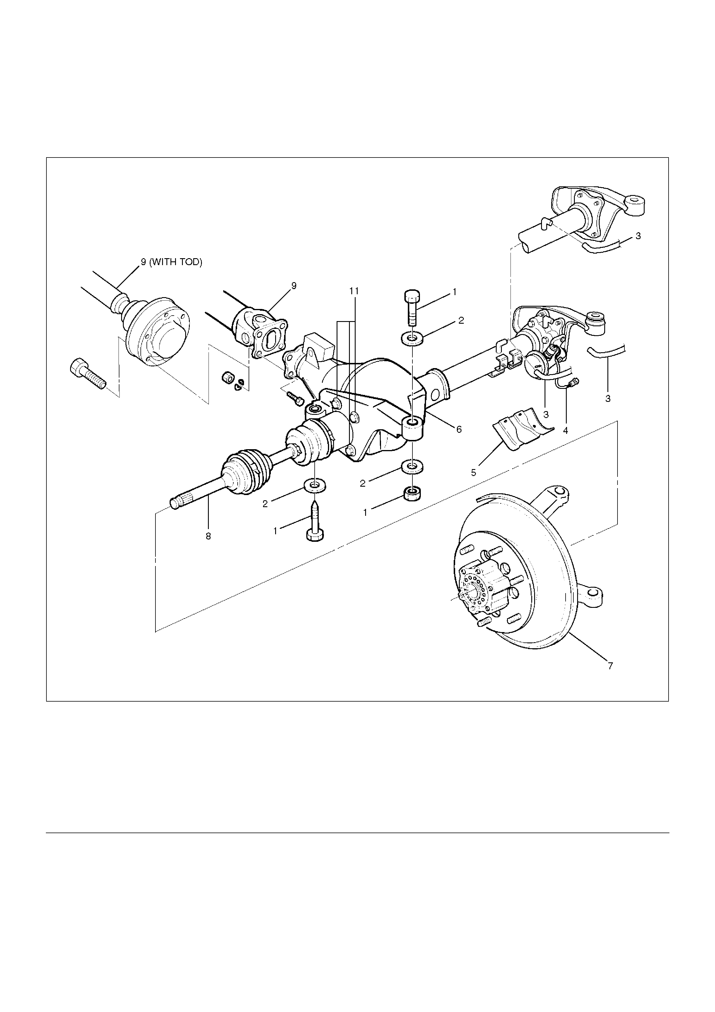
Front Drive Axle Assembly
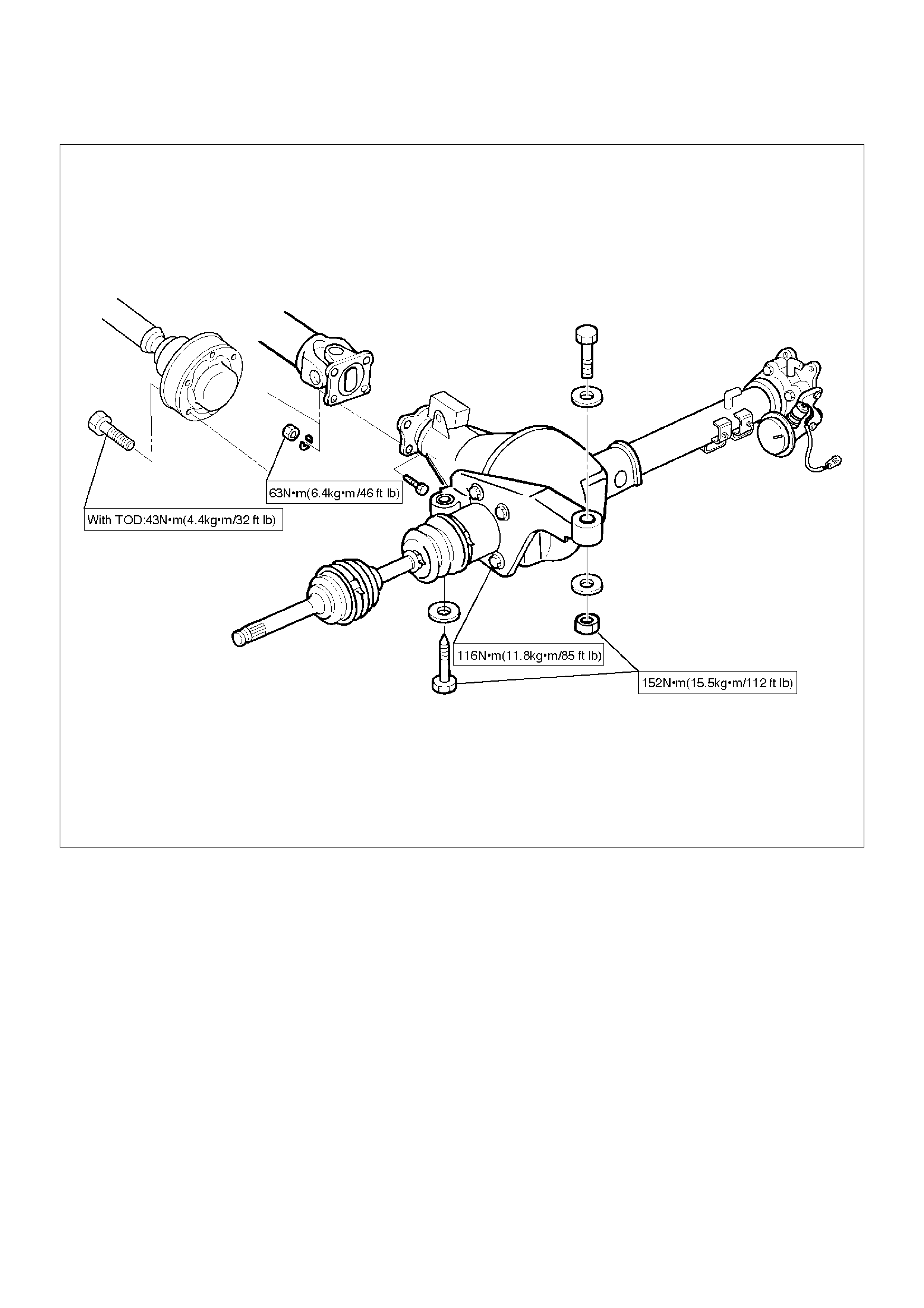
Front Drive Axle Assembly and Associated Parts
412RY00001
EndOFCallout
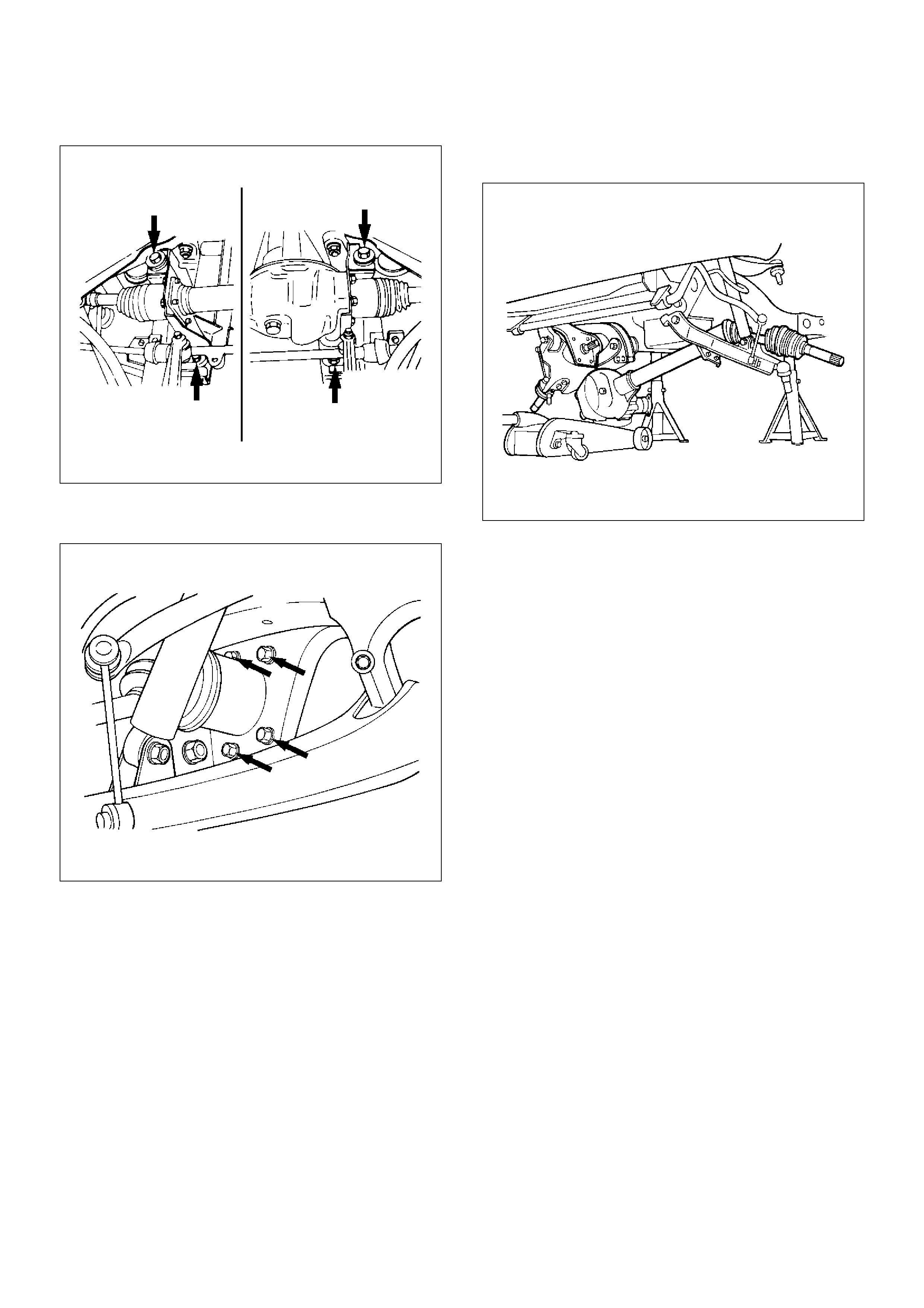
Removal
1. Jack up the vehicle and support it using jack stands.
2. Remove the tire and wheel.
Legend
(1) Mounting Bolt and Nut
(2) Washer and Spacer
(3) Breather Hose
(4) Shift Switch Connector (with Shift on the Fly)
(5) Protector (with Shift on the Fly)
(6) Front Axle Case Assembly and Front Drive
Shaft Assembly (LH side)
(7) Hub Assembly (Disc, Back Plate and Knuckle)
(8) Front Drive Shaft Assembly (RH side)
(9) Propeller Shaft
(10) Bolt
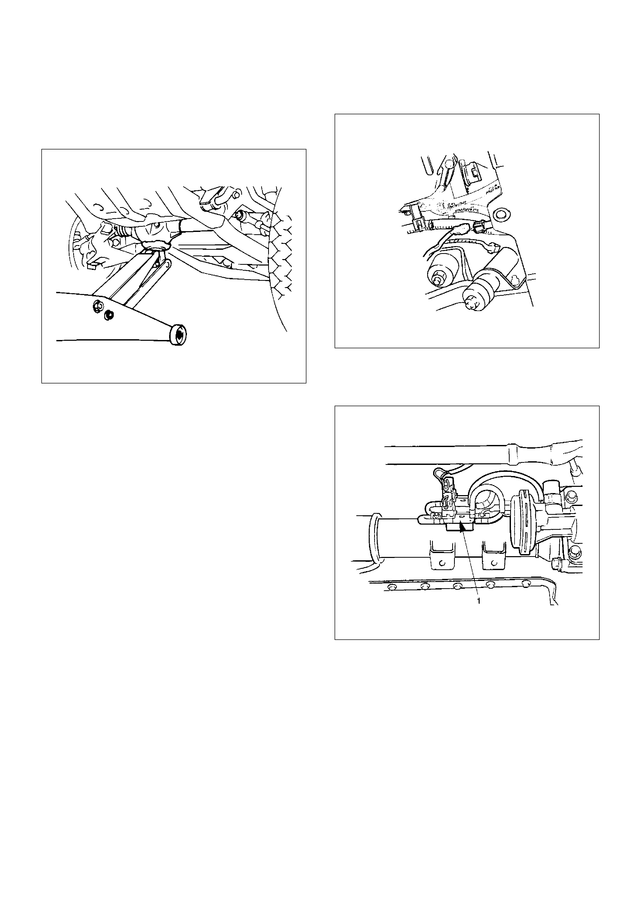
3.Remove the drain bolt to drain differential oil.
NOTE:
aDuring the work, be sure that the diff case is
supported by the jack.
412RS003
bRemove the brake caliper fixing bolt and hang the
caliper. Refer to Front Disc Brake Caliper Assembly
in Brake section.
cRemove the antilock brake system speed sensor (if
equipped). Refer to Front Wheel Speed Sensor in
Brakes section.
4.Remove the hub assembly (Disc, back plate and
knuckle), refer to Front Hub and Disc in this section.
5.Disconnect the knuckle and the suspension arm.
Refer to Suspension section.
6.Remove steering link and arm assembly, refer to
Steering Linkage in Steering section.
7.Remove suspension crossmember.
8.Remove propeller shaft, refer to Front Propeller
Shaft in this section.
9. Remove protector (Shift on the fly model).
10. Remove the hose clip.
11. Disconnect breather hose from front drive axle tube.
(and disconnect housing : Shift on the fly model).
12. Disconnect vacuum hose from actuator (Shift on the
fly model).
13. Disconnect shift switch connector (Shift on the fly
model).
412RS031
14. Remove VSV assembly (1) (Shift on the fly model).
NOTE: Be sure not to remove hose and connector from
VSV asm.
412RW002
15. Remove mounting bolt and nut.
412RS004
16. Remove washer and spacer.
17. Remove the mounting bracket fixing bolt.
412RS005
18. Lower the vehicle and disconnect the RH front drive
shaft assembly, then remove the front axle case
assembly and front drive shaft assembly (LH).
412RS006
19. Remove front drive shaft assembly (RH).
Installation
1. Install front drive shaft assembly (RH) and lay the
assembly on the lower arm.
2. Install front axle case assembly and front drive shaft
assembly (LH) and place the axle case on the jack,
connect to the front drive shaft assembly (RH)
before installing to the vehicle.
3. Install bolt and tighten the mounting bracket fixing
bolt to the specified torque.
Torque:116N·m (11.8kg·m/85 lbft)
4. Install washer and spacer.
5.Tighten the mounting bolt and nut to the specified
torque.
Torque:152N·m (15.5kg·m/112lbft)
412RW005
EndOFCallout
6. Install VSV assembly and tighten nuts to specified
torque (Shift on the fly model).
Torque:8N·m (0.8kg·m/69lbin)
7. Install the shift switch connector (Shift on the fly
model).
NOTE: Be careful not to permit the entry of dust into
the connector.
8. Install the actuator side of vacuum hose (Shift on
the fly model).
NOTE: Be careful not to permit the entry of dust into
the hose.
9.Connect breather hose and install the hose clip.
10.Install protector and tighten bolts to specified torque
(Shift on the fly model).
Torque:26N·m (2.7kg·m/20lbft)
11.Install propeller shaft, refer to Front Propeller Shaft
in this section.
12. Install suspension crossmember.
13.Steering link and arm assembly, refer to Steering
Linkage in Steering section.
14. Install hub assembly (Disc, back plate and knuckle),
refer to Front Hub and Disc in this section.
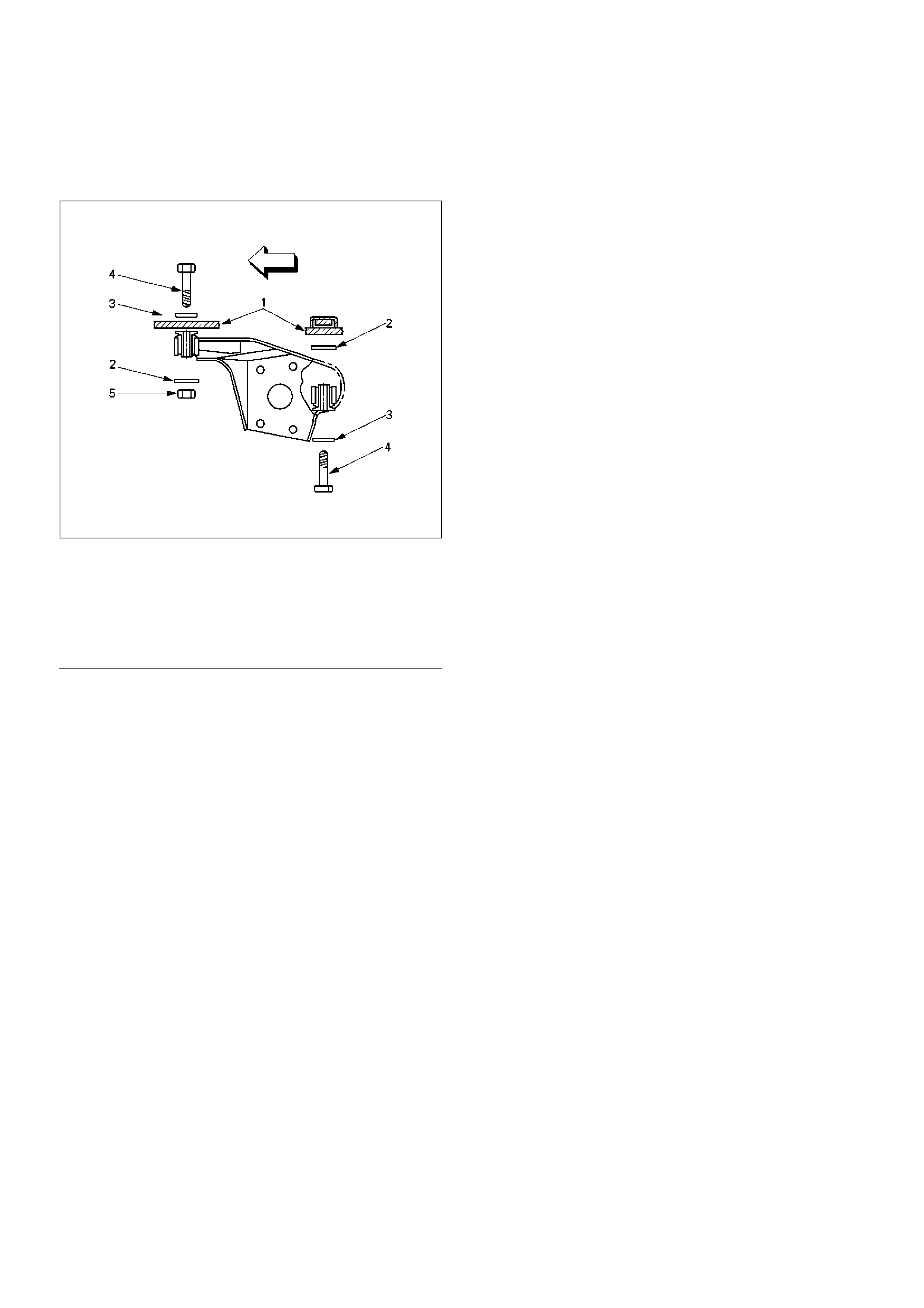
Legend
(1) Frame
(2) Spacer
(3) Washer
(4) Bolt
(5) Nut
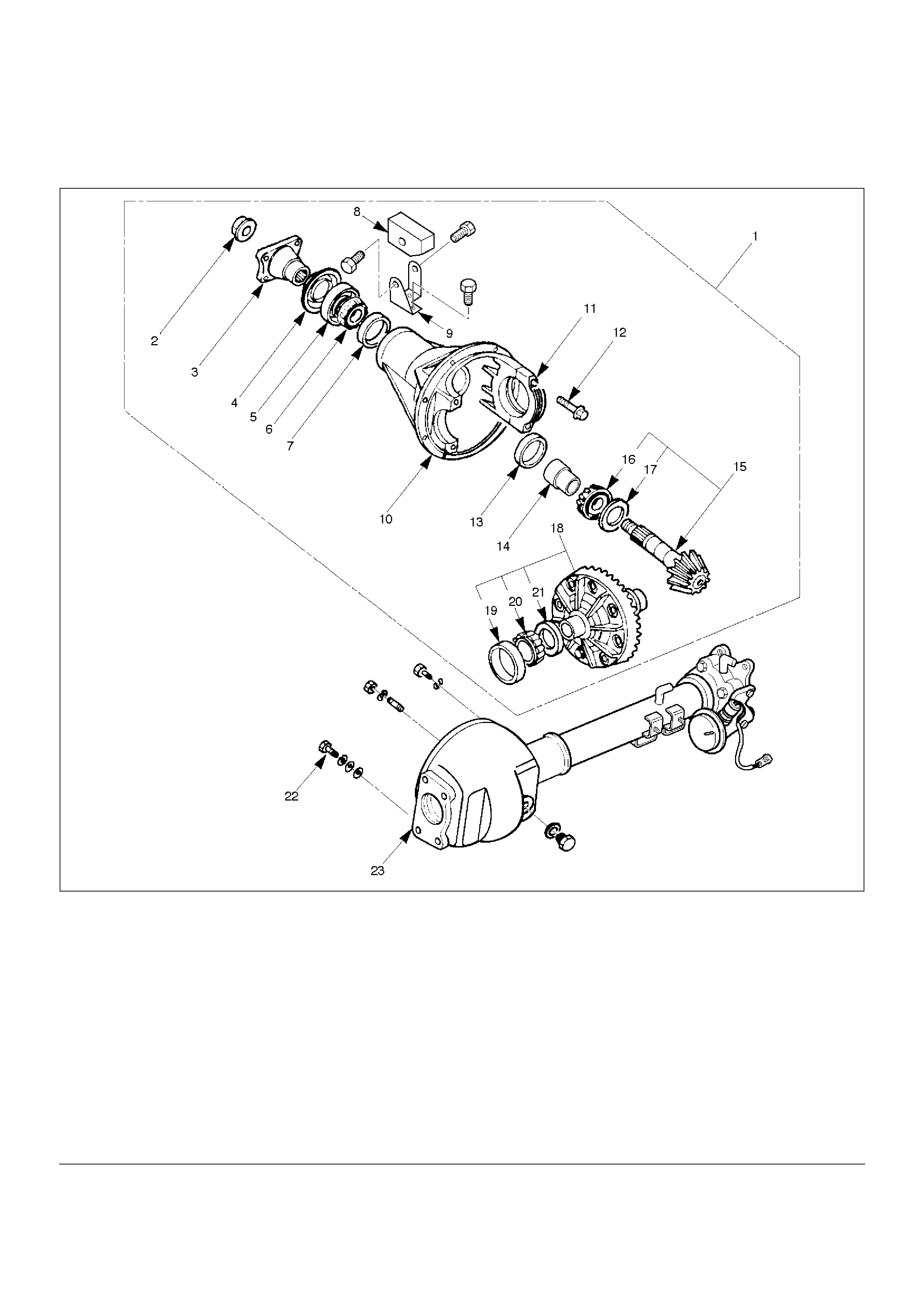
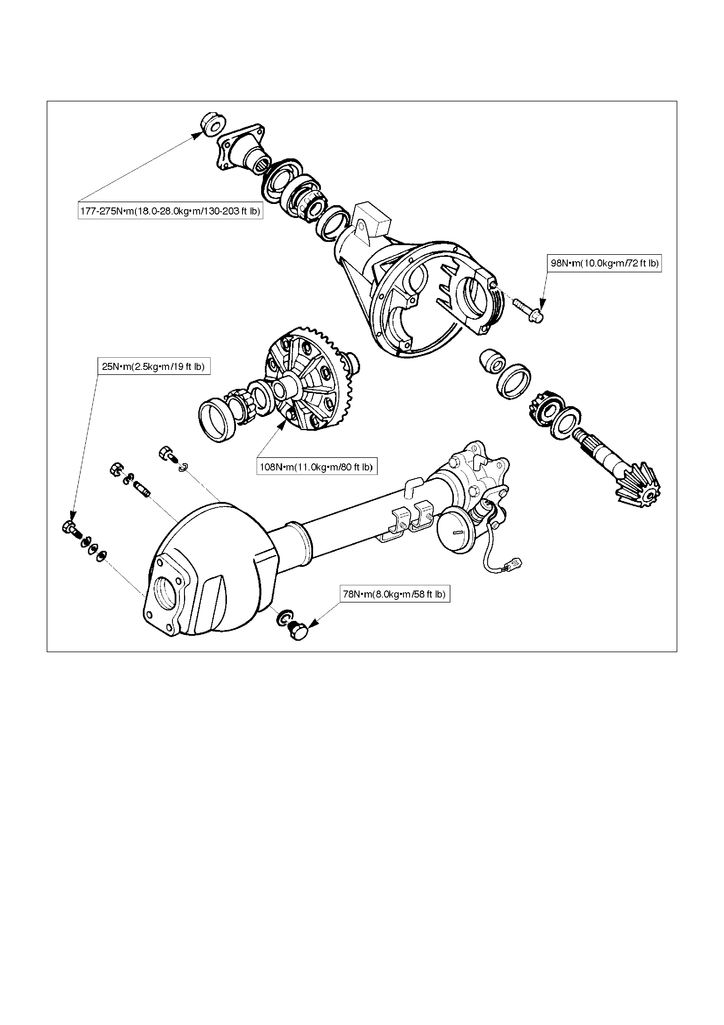
Differential Assembly
Disassembled View
415RW001
EndOFCallout
Legend
(1) Differential Assembly
(2) Flange Nut
(3) Flange
(4) Dust Cover
(5) Oil Seal
(6) Outer Bearing
(7) Outer Bearing Outer Race
(8) Damper
(9) Bracket
(10) Differential Carrier
(11) Bearing Cap
(12) Bolt
(13) Inner Bearing Outer Race
(14) Collapsible Spacer
(15) Pinion Gear
(16) Inner Bearing
(17) Adjust Shim
(18) Diff Cage Assembly
(19) Side Bearing Outer Race
(20) Side Bearing
(21) Adjust Shim
(22) Bolt
(23) Axle Case
Disassembly
1. Remove differential carrier fixing bolt.
2. Remove differential assembly.
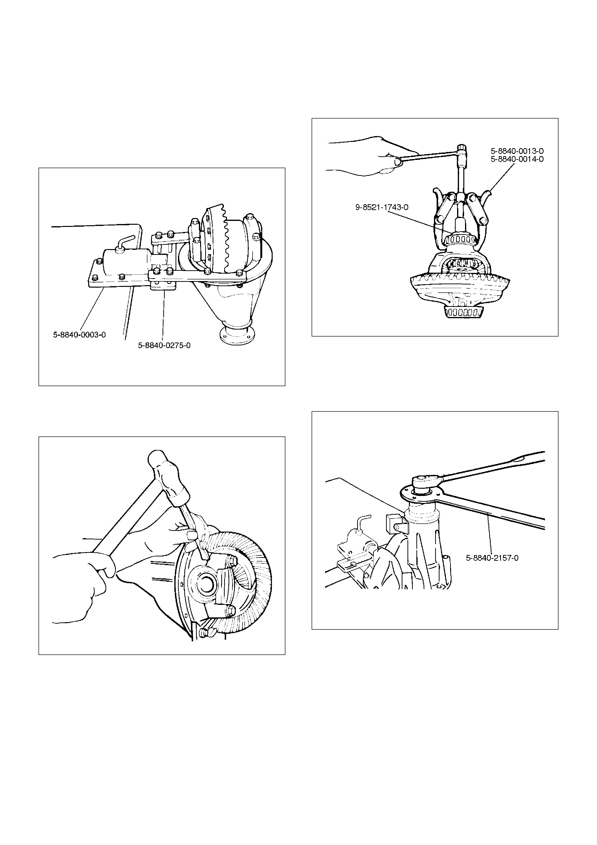
3. Using holding fixture 5–8840–0275–0 and holding
fixture base 5–8840–0003–0, fix the differential
assembly to the bench.
425RW046
4. Remove bearing cap bolt.
5. Apply a setting mark to the side bearing cap and the
differential carrier then remove bearing cap.
425RS009
6. Remove differential cage assembly.
7. Remove side bearing outer race, after removal,
keep the right and left hand side bearing assemblies
separate to maintain inner and outer race
combinations.
8. Remove side bearing, using remover 5–8840–
0013–0, 5–8840–0014–0 and adapter 9–8521–
1743–0.
415RW023
9. Remove adjust shim, note the thickness and
position of the shims removed.
10. Remove the flange nut using holding wrench 5–
8840–2157–0 after raising up its staked parts
completely.
425RW047
11. Remove flange.
12. Remove dust cover.
13. Remove the drive pinion assembly using a soft
metal rod and a hammer.
425RW041
14. Remove collapsible spacer.
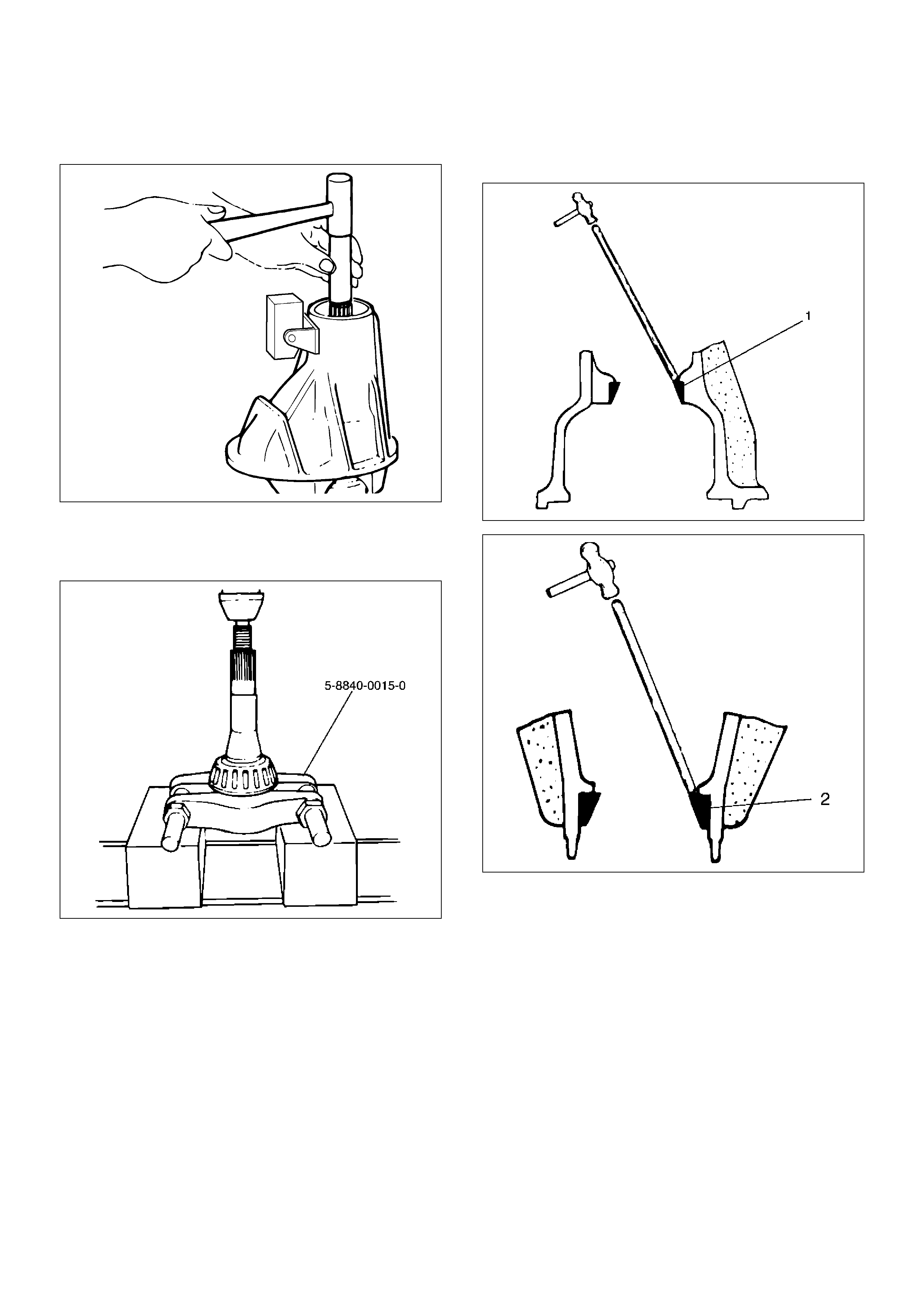
15. Remove the inner bearing using a separator 5–
8840–0015–0 and a press.
415RW033
16. Remove adjust shim.
17. Remove inner bearing outer race.
18. Remove oil seal.
19. Remove outer bearing.
20. Remove the inner bearing outer race (1) and the
outer bearing outer race (2) by using a brass bar
and a hammer.
425RS014
425RS015
21. Remove damper and bracket.
425RW042
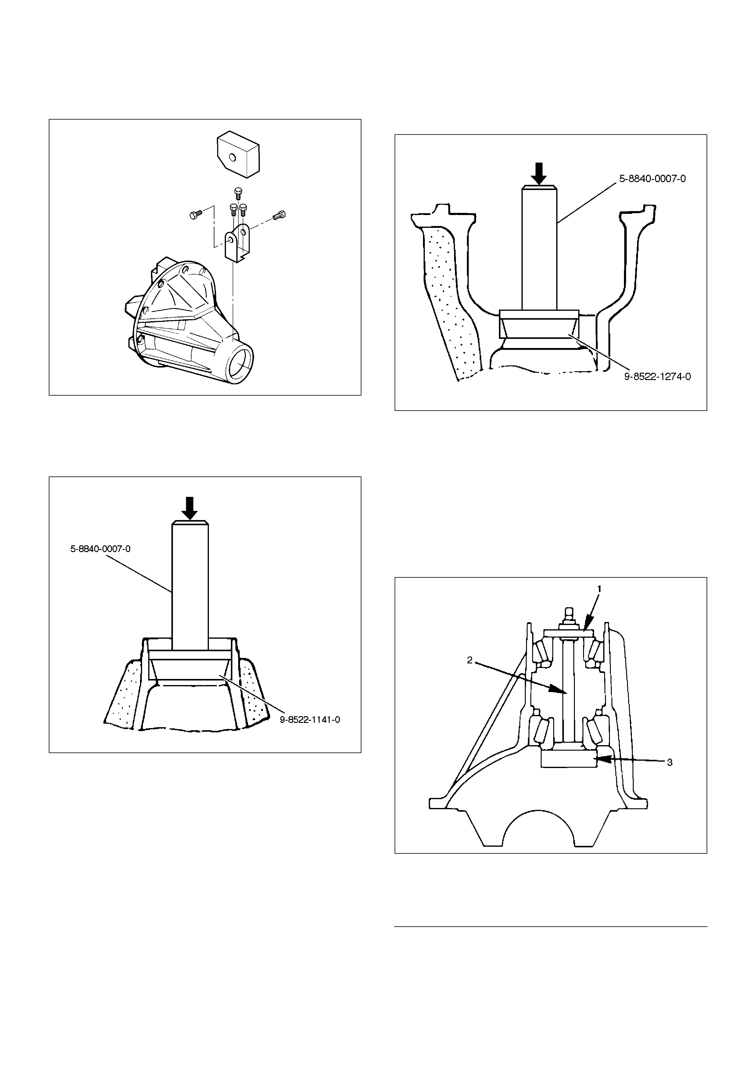
Reassembly
1. Using installer 9–8522–1141–0 and grip 5–8840–
0007–0, install outer bearing outer race.
415RW018
2. Using installer 9–8522–1274–0 and grip 5–8840–
0007–0, install Inner bearing outer race.
415RW017
3. Install adjust shim and adjust drive pinion mounting
distance
1. Apply gear oil to the inner and outer drive pinion
bearing.
Clean the pinion setting gauge set.
Then install the gauge set together with the
inner and outer bearings.
2. Tighten the nut to the specified torque.
Torque:2.3N·m (0.23kg·m/20lbin)
415RS009
EndOFCallout
Legend
(1) Pilot : 5–8840–2085–0
(2) Nut and Bolt : 5–8840–2089–0
(3) Gauge Plate : 5–8840–2087–0
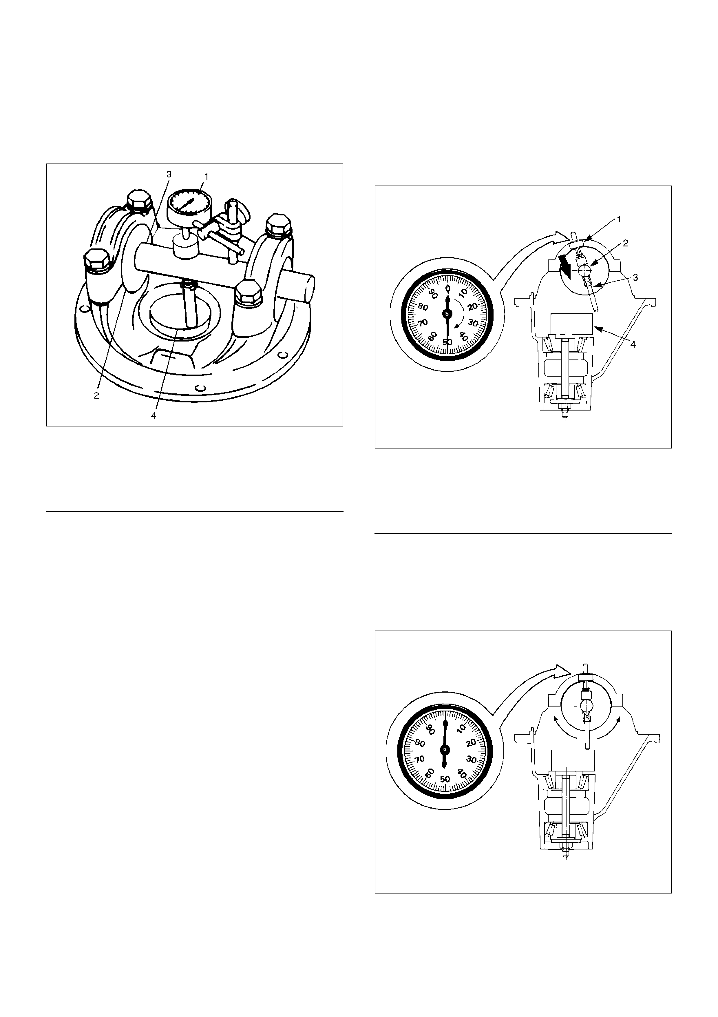
3. Clean the side bearing bores. Install the dial
indicator with the discs and arbor. Install and
tighten the bearing caps to the specified torque.
Torque:98N·m (10kg·m/72lbft)
415RS010
EndOFCallout
4. Set the dial indicator to“0”. Place it on the
mounting post of the gauging arbor with the
contact button touching the indicator pad. Force
the dial indicator downward until the needle has
made a half turn clockwise. Tighten down the
dial indicator in this position.
425RS020
EndOFCallout
5. Position the plunger on the gauge plate. Move
the gauging arbor slowly back and forth and
locate the position at which the dial indicator
shows the greatest defection. At this point, once
again set the dial indicator to“0”.
Repeat the procedure to verify the “0” setting.
425RS021
Legend
(1) Dial Indicator: 5–8840–0126–0
(2) Disc (2 pcs.): 5-8840-2088-0
(3) Arbor: 5–8840–0128–0
(4) Gauge Plate: 5–8840–2087–0
Legend
(1) Dial Indicator
(2) Gauging Arbor
(3) Plunger
(4) Gauge Plate
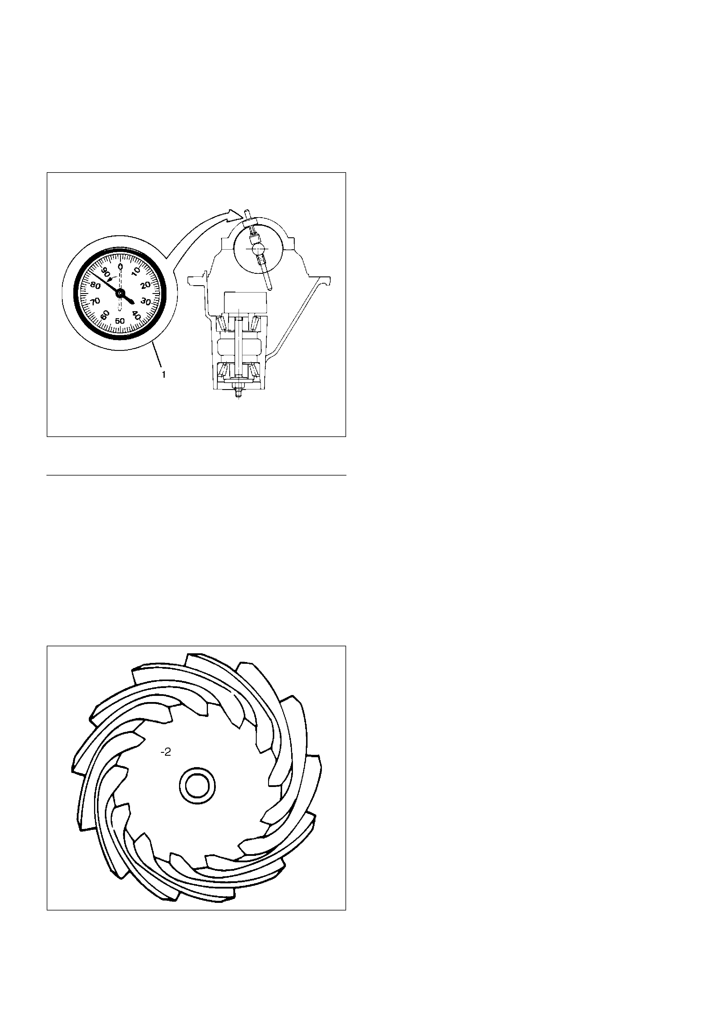
6. After the ZERO setting is obtained, rotate the
gauging arbor until the dial indicator rod does
not touch the gauging plate.
Record the number the dial indicator needle
points to.
425RS022
EndOFCallout
7. Record the pinion depth code on the head of
the drive pinion.
The number indicates a necessary change in
the pinion mounting distance. A plus number
indicates the need for a greater mounting
distance (which can be achieved by decreasing
the shim thickness). A minus number indicates
the need for a smaller mounting distance (which
can be achieved by increasing the shim
thickness). If examination reveals pinion depth
code“0”, the pinion is“nominal”.
425RS023
Legend
(1) Example=Dial indicator reading of 0.085

8. Select the shim using the chart;
Pinion
marking +10 +8 +6 +4 +2 0 –2 –4 –6 –8 –10
Dial
indicator
reading
(Inches)
mm
(Inches)
mm
(Inches)
mm
(Inches)
mm
(Inches)
mm
(Inches)
mm
(Inches)
mm
(Inches)
mm
(Inches)
mm
(Inches)
mm
(Inches)
mm
(Inches)
0.081 2.18
(0.0858)
0.082 2.18
(0.0858)
2.20
(0.0866)
0.083 2.18
(0.0858)
2.20
(0.0866)
2.23
(0.0882)
0.084 2.18
(0.0858)
2.20
(0.0866)
2.24
(0.0882)
2.26
(0.0890)
0.085 2.18
(0.0858)
2.20
(0.0866)
2.24
(0.0882)
2.26
(0.0890)
2.28
(0.0898)
0.086 2.18
(0.0858)
2.20
(0.0866)
2.24
(0.0882)
2.26
(0.0890)
2.28
(0.0898)
2.32
(0.0914)
0.087 2.18
(0.0858)
2.20
(0.0866)
2.24
(0.0882)
2.26
(0.0890)
2.28
(0.0898)
2.32
(0.0914)
2.34
(0.0921)
0.088 2.18
(0.0858)
2.20
(0.0866)
2.24
(0.0882)
2.26
(0.0890)
2.28
(0.0898)
2.32
(0.0914)
2.34
(0.0921)
2.36
(0.0929)
0.089 2.18
(0.0858)
2.20
(0.0866)
2.24
(0.0882)
2.26
(0.0890)
2.28
(0.0898)
2.32
(0.0914)
2.34
(0.0921)
2.36
(0.0929)
2.38
(0.0937)
0.090 2.18
(0.0858)
2.20
(0.0866)
2.24
(0.0882)
2.26
(0.0890)
2.28
(0.0898)
2.32
(0.0914)
2.34
(0.0921)
2.36
(0.0929)
2.38
(0.0937)
2.42
(0.0953)
0.091 2.18
(0.0858)
2.20
(0.0866)
2.24
(0.0882)
2.26
(0.0890)
2.28
(0.0898)
2.32
(0.0914)
2.34
(0.0921)
2.36
(0.0929)
2.38
(0.0937)
2.42
(0.0953)
2.44
(0.0961)
0.092 2.20
(0.0866)
2.24
(0.0882)
2.26
(0.0890)
2.28
(0.0898)
2.32
(0.0914)
2.34
(0.0921)
2.36
(0.0929)
2.38
(0.0937)
2.42
(0.0953)
2.44
(0.0961)
2.46
(0.0969)
0.093 2.24
(0.0882)
2.26
(0.0890)
2.28
(0.0898)
2.32
(0.0914)
2.34
(0.0921)
2.36
(0.0929)
2.38
(0.0937)
2.42
(0.0953)
2.44
(0.0961)
2.46
(0.0969)
2.48
(0.0977)
0.094 2.26
(0.0890)
2.28
(0.0898)
2.32
(0.0914)
2.34
(0.0921)
2.36
(0.0929)
2.38
(0.0937)
2.42
(0.0953)
2.44
(0.0961)
2.46
(0.0969)
2.48
(0.0977)
2.52
(0.0992)
0.095 2.28
(0.0898)
2.32
(0.0914)
2.34
(0.0921)
2.36
(0.0929)
2.38
(0.0937)
2.42
(0.0953)
2.44
(0.0961)
2.46
(0.0969)
2.48
(0.0977)
2.52
(0.0992)
2.54
(0.1000)
0.096 2.32
(0.0914)
2.34
(0.0921)
2.36
(0.0929)
2.38
(0.0937)
2.42
(0.0953)
2.44
(0.0961)
2.46
(0.0969)
2.48
(0.0977)
2.52
(0.0992)
2.54
(0.1000)
2.56
(0.1008)
0.097 2.34
(0.0921)
2.36
(0.0929)
2.38
(0.0937)
2.42
(0.0953)
2.44
(0.0961)
2.46
(0.0969)
2.48
(0.0977)
2.52
(0.0992)
2.54
(0.1000)
2.56
(0.1008)
0.098 2.36
(0.0929)
2.38
(0.0937)
2.42
(0.0953)
2.44
(0.0961)
2.46
(0.0969)
2.48
(0.0977)
2.52
(0.0992)
2.54
(0.1000)
2.56
(0.1008)
0.099 2.38
(0.0937)
2.42
(0.0953)
2.44
(0.0961)
2.46
(0.0969)
2.48
(0.0977)
2.52
(0.0992)
2.54
(0.1000)
2.56
(0.1008)
02.42
(0.0953)
2.44
(0.0961)
2.46
(0.0969)
2.48
(0.0977)
2.52
(0.0992)
2.54
(0.1000)
2.56
(0.1008)
0.001 2.44
(0.0961)
2.46
(0.0969)
2.48
(0.0977)
2.52
(0.0992)
2.54
(0.1000)
2.56
(0.1008)
0.002 2.46
(0.0969)
2.48
(0.0977)
2.52
(0.0992)
2.54
(0.1000)
2.56
(0.1008)
0.003 2.48
(0.0977)
2.52
(0.0992)
2.54
(0.1000)
2.56
(0.1008)

NOTE: When ordering shims, find the part number in
the parts catalog by using the thickness of shims listed
in the above table.
4. Place the shim on the drive pinion, with the
chamfered side turned towards the pinion head then
install the inner bearing onto the pinion using an
installer 9–8522–1165–0 and a press.
0.004 2.52
(0.0992)
2.54
(0.1000)
2.56
(0.1008)
0.005 2.54
(0.1000)
2.56
(0.1008)
0.006 2.56
(0.1008)
Pinion
marking +10 +8 +6 +4 +2 0 –2 –4 –6 –8 –10
Dial
indicator
reading
(Inches)
mm
(Inches)
mm
(Inches)
mm
(Inches)
mm
(Inches)
mm
(Inches)
mm
(Inches)
mm
(Inches)
mm
(Inches)
mm
(Inches)
mm
(Inches)
mm
(Inches)
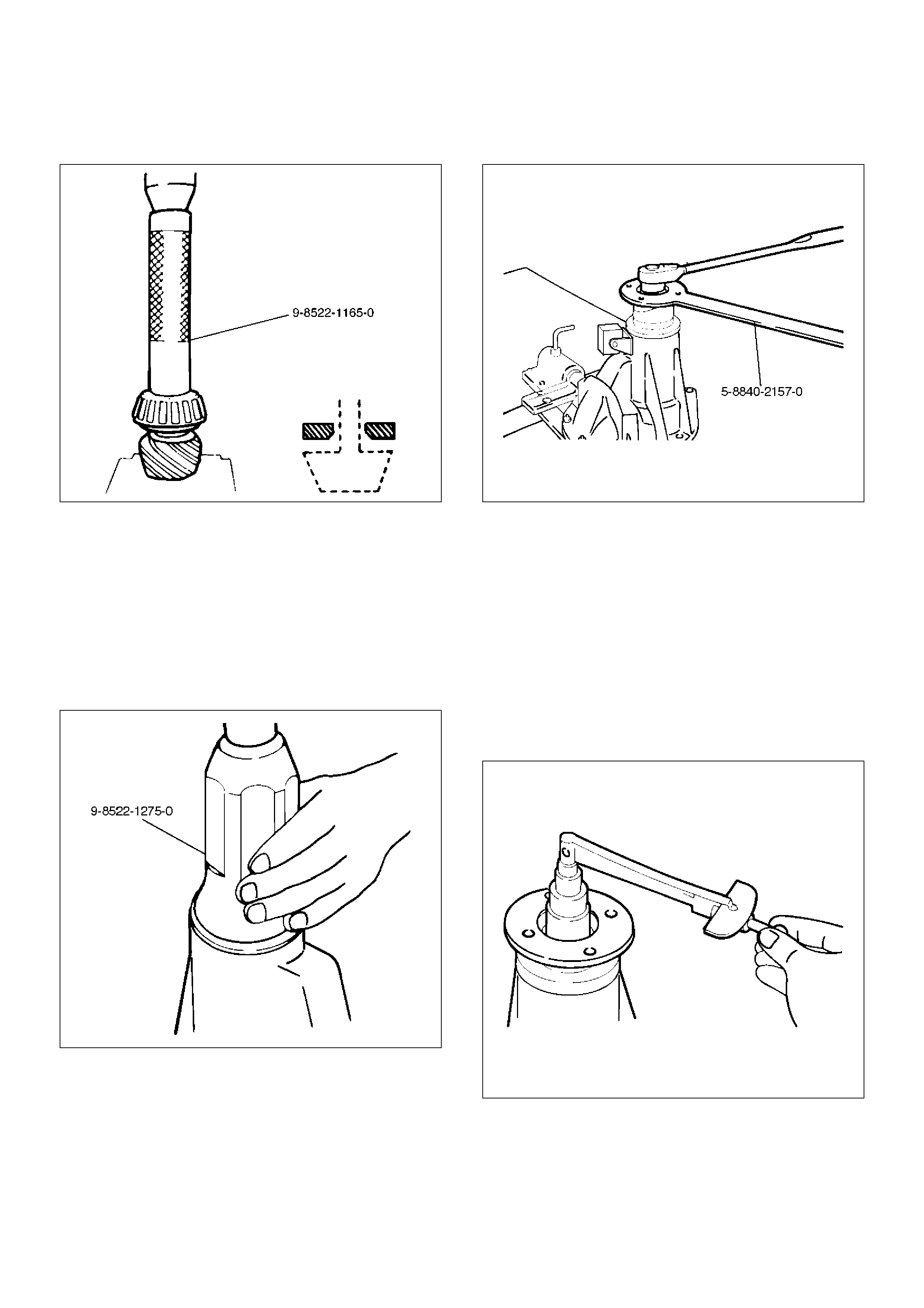
NOTE: Do not apply pressure to the roller cage and
apply pressure only to the inner race.
425RW048
5. Discard the used collapsible spacer and install a
new one.
6. Install pinion gear.
7. Install outer bearing.
8. Use oil seal installer 9–8522–1275–0 to install a
new oil seal that has been soaked in rear axle
lubricant.
NOTE: Take care to use a front differential oil seal,
NOT the rear differential oil seal.
415RW024
9. Install dust cover.
10. Install flange.
11. Install flange nut.
1. Apply lubricant to the pinion threads.
2. Tighten the nut to the specified torque using the
pinion flange holder 5–8840–2157–0.
Torque:177–275N·m(18–28kg·m/130–203lbft)
NOTE: Discard used flange nut and install new one
and do not over tighten the flange nut.
425RW047
3. Adjust pinion bearing preload.
a Measure the bearing preload by using a
torque meter. Note the scale reading
required to rotate the flange.
b Continue tightening flange nut until the
specified starting torque is obtained.
Starting torque:
New bearing 0.7–1.1N·m(0.065–0.115kg·m/5.64–
9.98lbin)
Used bearing 0.4–0.5N·m(0.033–0.057kg·m/2.86–
4.94Ibin)
425RS027
4. Using punch 5-8840-2293-0, stake the flange
nut at two points.
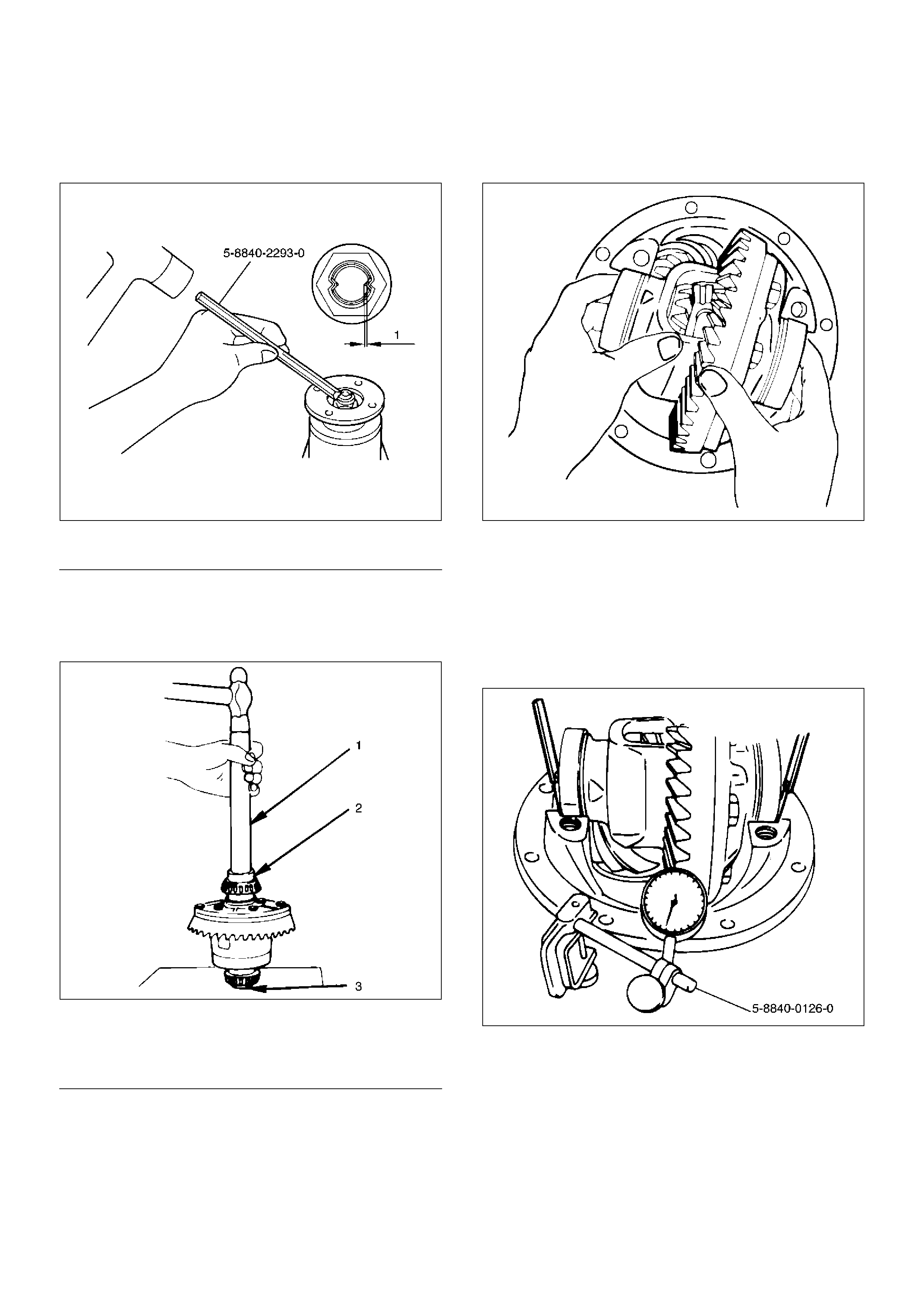
NOTE: When staking, be sure to turn the nut to insure
that there is no change in bearing preload. Make sure of
preload again as instructed in 3).
415RW019
EndOFCallout
12. Install adjust shim.
1. Attach the side bearing to the differential
assembly without shims. Support the opposite
side using a pilot to prevent bearing damage.
425RS029
EndOFCallout
2. Insert the differential cage assembly with
bearing outer races into the side bearing bores
of the carrier.
425RS030
3. Using two sets of feeler gauges, insert a feeler
stock of sufficient thickness between each
bearing outer race and the carrier to remove all
end play. Make certain the feeler stock is
pushed to the bottom of the bearing bores.
Mount the dial indicator 5–8840–0126–0 on the
carrier so that the indicator stem is at right
angles to a tooth on the ring gear.
425RW049
Legend
(1) 1.3mm or less
Legend
(1) Drive handle:5–8840–0007–0
(2) Installer:9–8522–1164–0
(3) Pilot:9–8521–1743–0
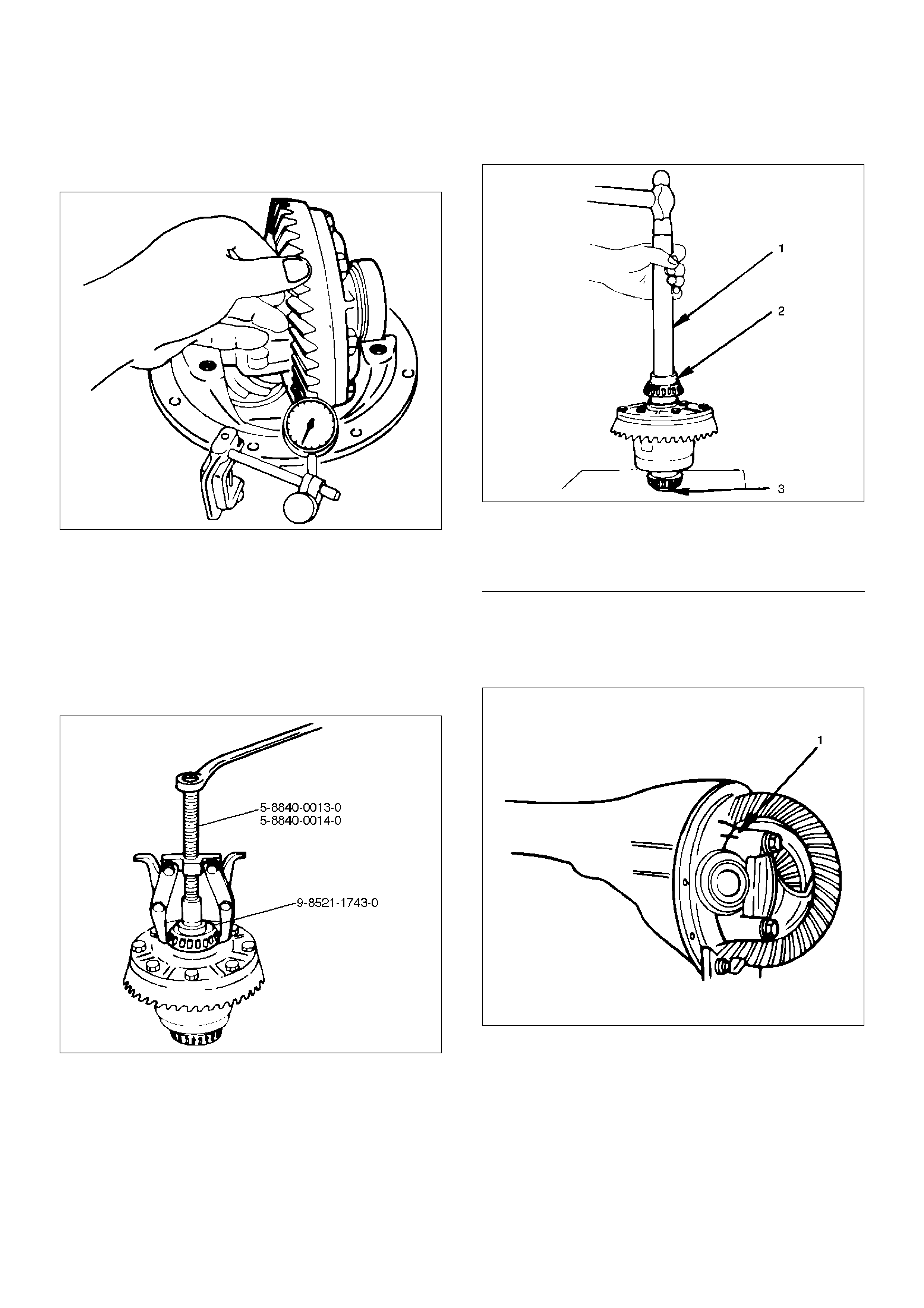
4. Adjust feeler gauge thickness from side to side
until ring gear backlash is in the specified range.
Backlash:0.13–0.18mm(0.005 –0.007in)
425RS032
With zero end play and correct backlash
established, remove the feeler gauge packs,
determine the thickness of the shims required
and add 0.05 mm (0.002 in) to each shim pack
to provide side bearing preload. Always use new
shims.
5. Use bearing remover 5–8840–0013–0 and 5–
8840–0014–0 and pilot 9–8521–1743–0 to
remove side bearing.
415RW020
13. Install the side bearings together with the selected
shims.
425RS029
EndOFCallout
14. Install side bearing outer race.
15. Install differential cage assembly.
16. Install bearing cap then align the setting marks(1)
applied at disassembly.
425RS035
Legend
(1) Drive Handle:5–8840–0007–0
(2) Installer: 9–8522–1164–0
(3) Pilot: 9–8521–1743–0
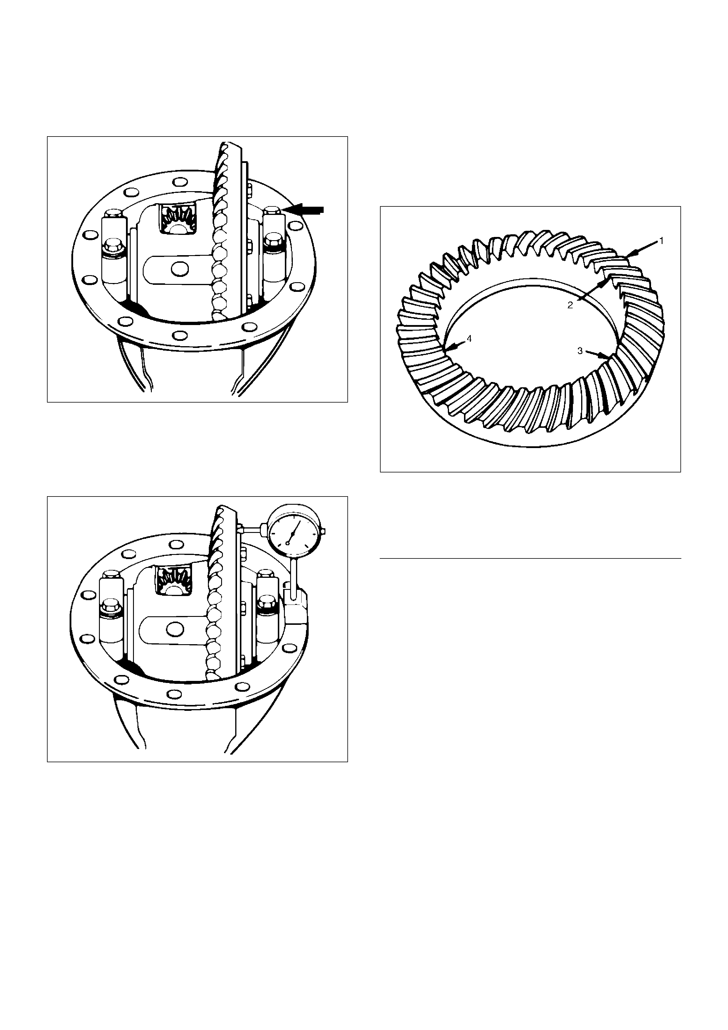
17. Tighten the cap bolt to the specified torque.
Torque:98N·m (10kg·m/72lbft)
425RS036
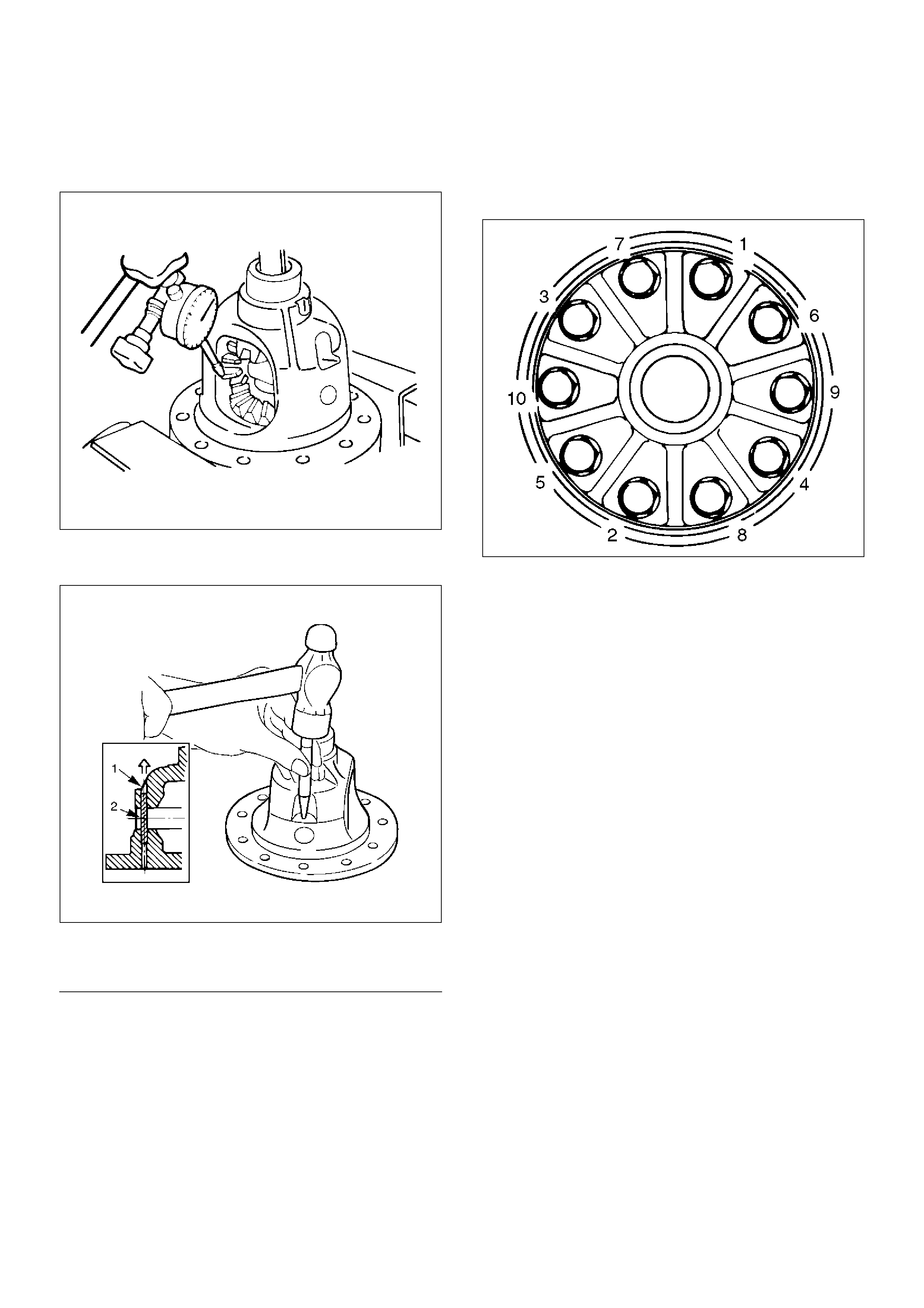
1. Measure the amount of run–out of the ring gear
at its rear face.
Standard:0.02mm (0.001in)
Limit:0.05mm(0.002in)
425RS037
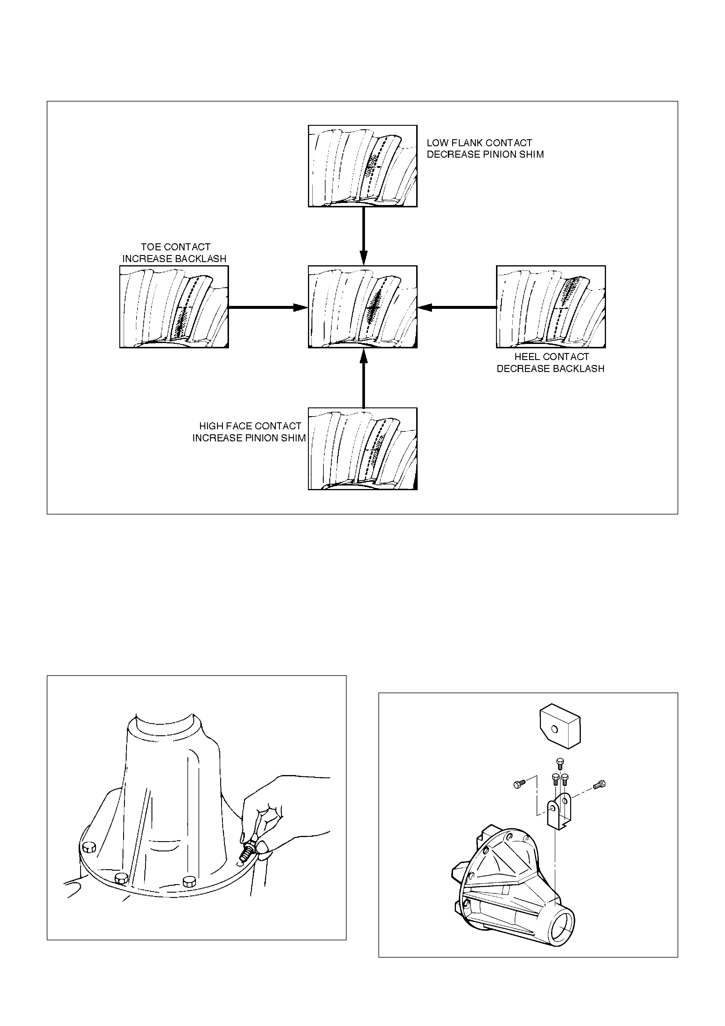
Gear Tooth Contact Pattern Check and Adjustment
1. Apply a thin coat of prussian blue or
equivalent to the faces of the 7–8 teeth of
the ring gear. Check the impression of
contact on the ring gear teeth and make
necessary adjustment as described in
illustration if the contact is abnormal.
425RS038
EndOFCallout
Legend
(1) Heel
(2) Toe
(3) Concave Side(Coast)
(4) Convex Side(Drive)
425RS039
18. Install differential assembly.
1. Clean the faces of the front axle case and
differential carrier.
Apply Three Bond TB1215 or equivalent to the
sealing side of the axle case and the carrier.
2. Attach the differential case and the carrier
assembly to the front axle case and tighten the
nuts and bolts.
Torque:25N·m(2.5kg·m/19lbft)
415RS014
3. Fill the axle case with hypoid gear lubricant, to
just below the filler hole.
Lubricant capacity:1.4liter(1.2Impqt/1.5USqt)
19. Install damper.
1. Clean the faces and bolt thread hole of
differential carrier.
2. Install the bracket with new bolts.
3. Install the damper to the bracket with new bolts.
Torque:25N·m(2.5kg·m/19lbft)
425RW042
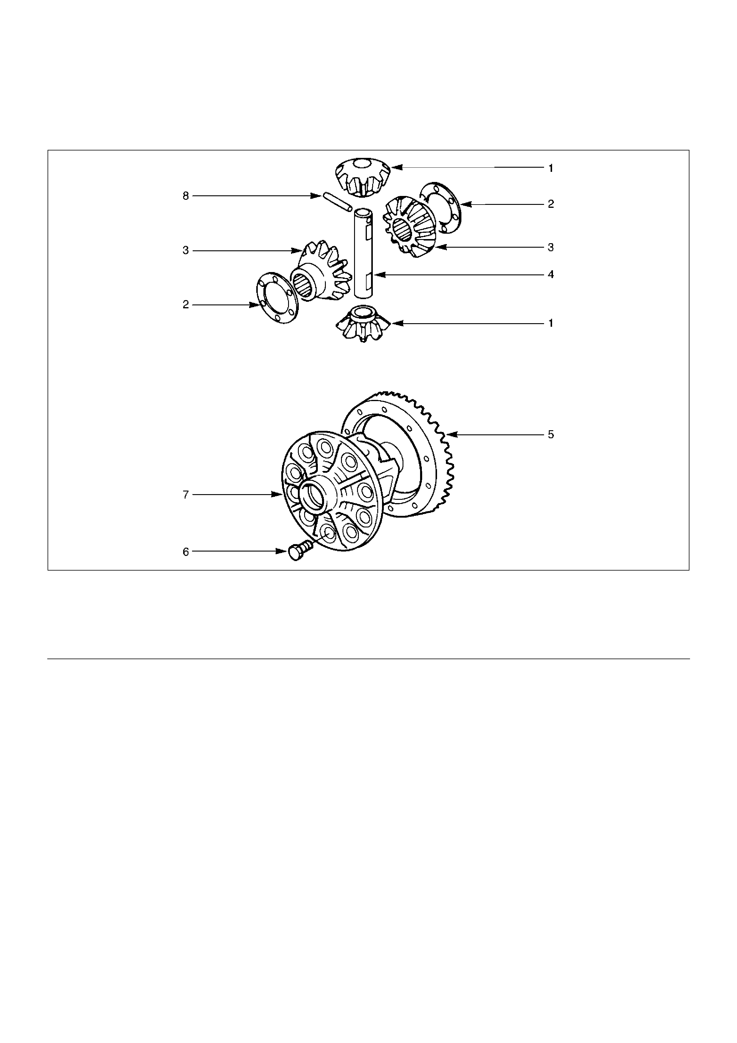
Differential Cage Assembly
Disassembled View
415RS015
EndOFCallout
Disassembly
1. Remove bolt.
2. Remove ring gear.
Legend
(1) Pinion Gear
(2) Thrust Washer
(3) Side Gear
(4) Cross Pin
(5) Ring Gear
(6) Bolt
(7) Differential Cage
(8) Lock Pin
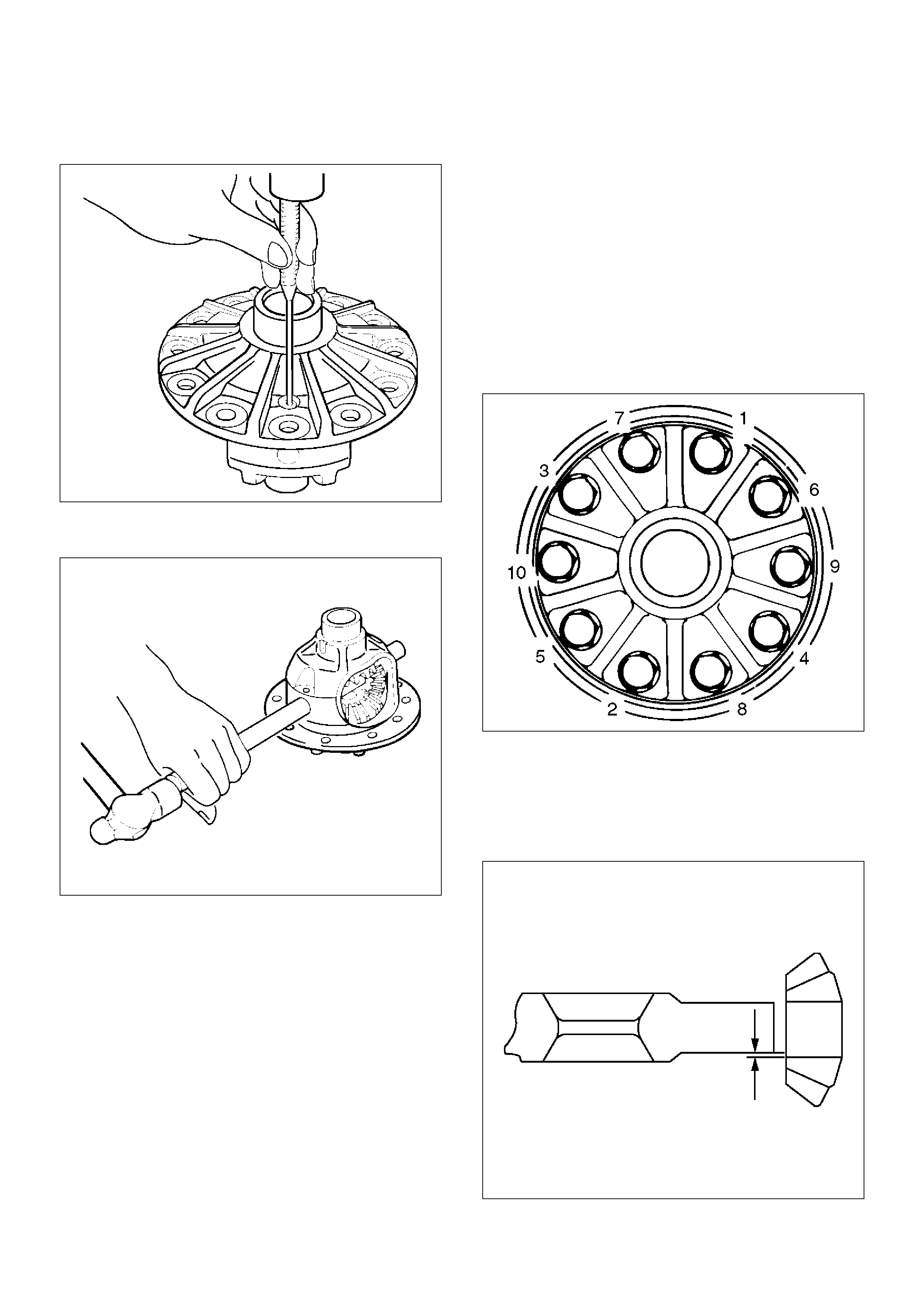
3. Remove lock pin, break staking on the lock pin,
using a 5 mm (0.20 in) diameter drill.
425RS042
4. Remove the cross pin, using a soft metal rod and a
hammer.
425RS043
5. Remove pinion gear.
6. Remove side gear.
7. Remove thrust washer.
Inspection and Repair
Make necessary correction or parts replacement if
wear, damage, corrosion or any other abnormal
conditions are found through inspection.
Check the following parts:
1. Ring gear, pinion gear
2. Bearing
3. Side gear, pinion gear, cross pin
4. Differential cage, carrier
5. Thrust washer
6. Oil seal
Ring gear replacement:
1. The ring gear should always be replaced with the
drive pinion as a set.
2. Clean the ring gear threaded holes to remove the
locking agent.
3. When installing the ring gear, apply LOCTITE 271 or
equivalent to all the threaded area and half of the
unthreaded area of the bolt.
4. Discard used bolts and install new ones.
Torque:108N·m(11kg·m/80lbft)
5. Tighten the fixing bolts in a diagonal sequence as
illustrated.
415RS016
Clearance between the differential pinion
and the cross pin measurement:
Standard:0.06 – 0.12mm (0.002–0.005in)
Limit:0.2mm(0.008in)
425RS045
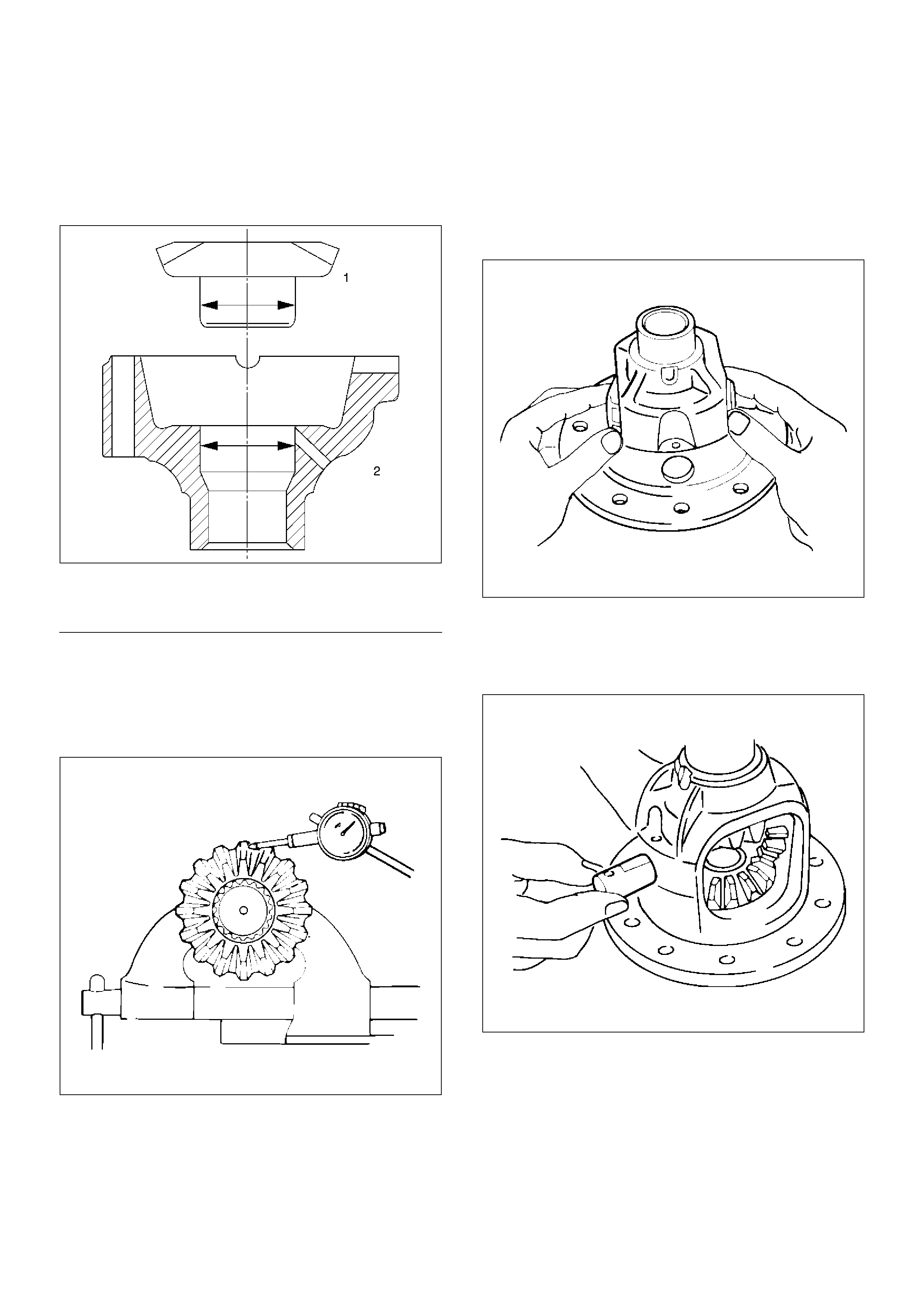
Clearance between the side gear and the
differential box:
Standard:0.03–0.10mm (0.001–0.004in)
Limit:0.15mm(0.006in)
425RS046
EndOFCallout
Play in splines between the side gear and
the axle shaft:
Standard:0.08–0.36mm(0.003 –0.014 in)
Limit:0.5m (0.02in)
425RS047
Reassembly
1. Install thrust washer.
2. Install side gear.
3. Install the pinion gear by engaging it with the side
gears while turning both pinion gears
simultaneously in the same direction.
425RS048
4. Install cross pin.
1. Be sure to install the cross pin so that it is in
alignment with the lock pin hole in the differential
cage.
425RS049
2. Adjust the backlash between the side gear and
the pinion gear.
Backlash:0.03 – 0.08mm (0.001– 0.003in)
Legend
(1) Side Gear
(2) Differential Box
Thickness of thrust washers available:
1.00mm, 1.05mm, 1.10mm(0.039in, 0.041in,
0.043in)
425RS050
5. Install lock pin. After lock pin installation, stake the
cage to secure the lock pin.
425RS051
EndOFCallout
6. Clean the ring gear threaded holes to remove the
locking agent. When installing the ring gear, apply
LOCTITE 271 or equivalent to all the threaded area
and half of the unthreaded area of the bolt.
7. Tighten the bolts in diagonal sequence as
illustrated.
Torque:108N·m(11kg·m/80lbft)
NOTE: Discard used bolts and install new ones.
415RS016
Legend
(1) Staked Portion
(2) Lock Pin
Main Data and Specifications
General Specifications
Axle tube Type It consists of the duct, a cast iron housing and the axle
tube.
Gear type Hypoid
Gear ratio (to 1) 4.100(6VE1)
4.300(4JX1, 6VE1)
4.555(4JG2–TC, 6VD1)
4.777(4JG2)
Differential type Two pinion
Oil capacity liter (Imp qt/US
qt)
1.4 (1.2/1.5) (Differential)
0.12 (0.11/0.13) (Actuator Housing: Shift on the fly)
Type of lubricant 75W–90 GL–5 (Multi grade type)
Refer to General Information
Axle shaft type Constant velocity joint (Birfield joint type and double offset
joint)
Torque Specifications
E04RW014
E04RW015
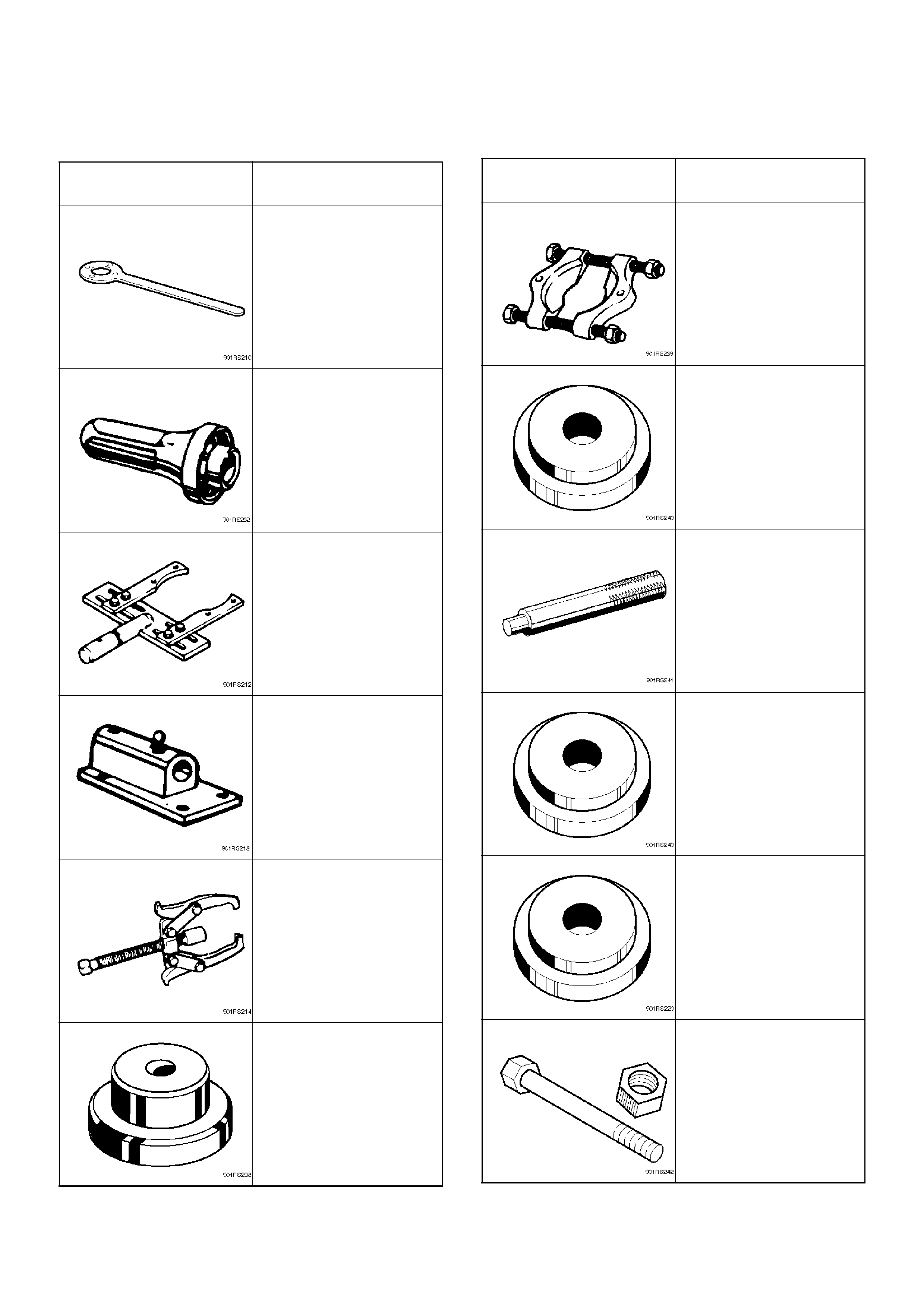
Special Tools
ILLUSTRATION TOOL NO.
TOOL NAME
5–8840–2157–0
(J–37221)
Holder; Pinion flange
9–8522–1275–0
(J–24250)
Installer; Oil seal
5–8840–0275–0
(J–37264)
Differential holding fixture
(Use with 5–8840–0003–
0 base)
5–8840–0003–0
(J–3289–20)
Holding fixture base
5–8840–0013–0
5–8840–0014–0
(J–22888)
Puller; Side bearing
9–8521–1743–0
(J–8107–2)
Adapter; Side bearing
plug
5–8840–0015–0
(J–22912–01)
Separator
9–8522–1141–0
(J–24256)
Installer; Outer bearing
outer race
5–8840–0007–0
(J–8092)
Driver handle
9–8522–1274–0
(J–24252)
Installer; Inner bearing
outer race
5–8840–2085–0
(J–21777–42)
Pilot
5–8840–2089–0
(J–23597–9)
Nut and bolt
ILLUSTRATION TOOL NO.
TOOL NAME
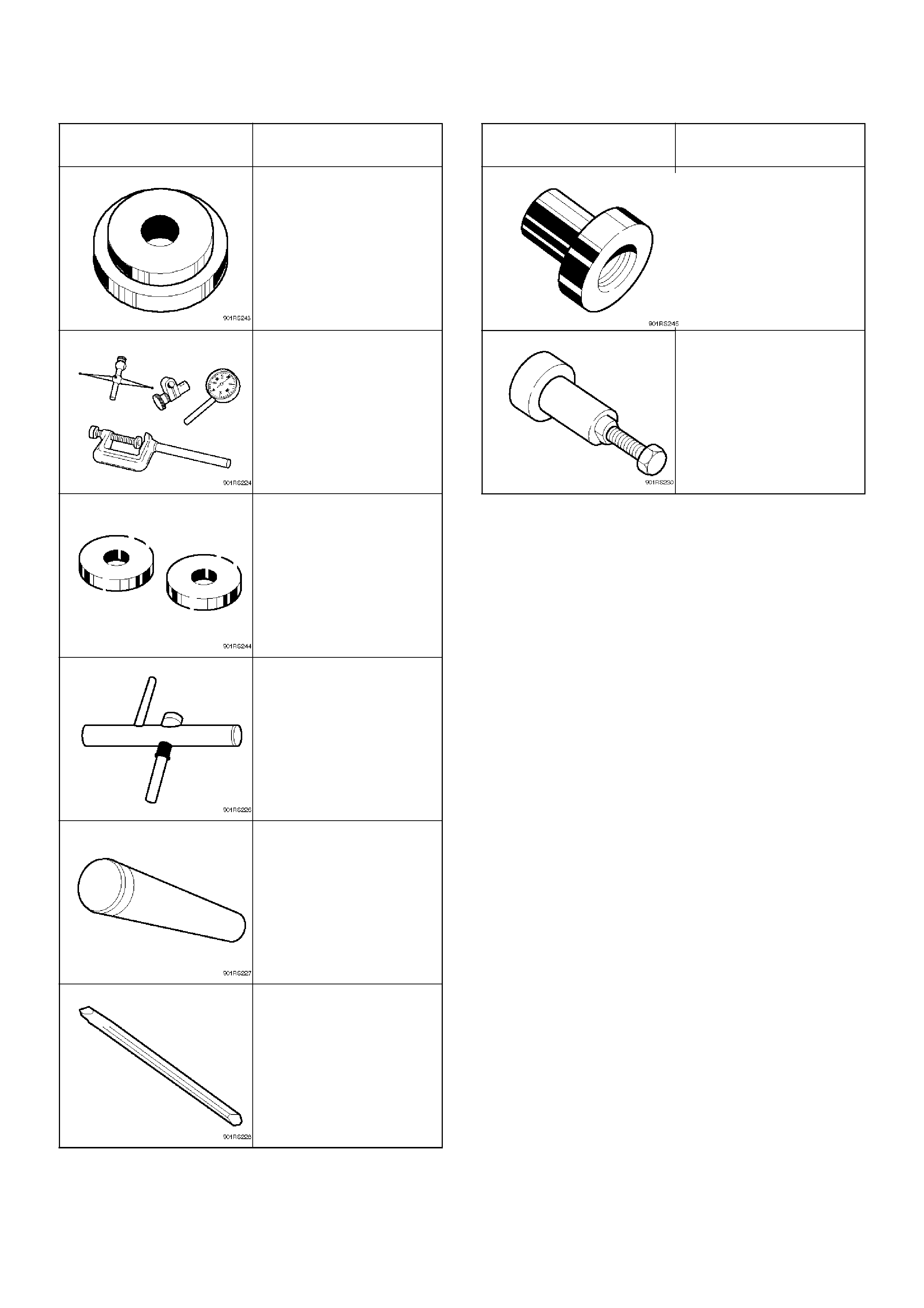
5–8840–2087–0
(J–23597–7)
Gauge plate
5–8840–0126–0
(J–8001)
Dial indicator
5–8840–2088–0
(J–23597–8)
Disc
5–8840–0128–0
(J–23597–1)
Arbor
9–8522–1165–0
(J–6133–01)
Installer; Pinion bearing
5–8840–2293–0
(J–39209)
Punch; End nut lock
ILLUSTRATION TOOL NO.
TOOL NAME
9–8522–1164–0
(J–24244)
Installer; Side bearing
5–8840–2323–0
(J–39602)
Remover; Outer bearing
ILLUSTRATION TOOL NO.
TOOL NAME