
SECTION 4C - REAR AXLE & DIFFERENTIAL
Service Precaution
General Description
Diagnosis
Axle Housing
Axle Housing and Associated Parts
Removal
Oil Seal Replacement
Installation
Axle Shaft
Axle Shaft and Associated Parts
Removal
Inspection and Repair
Oil Seal Replacement
Installation
Pinion Oil Seal
Pinion Oil Seal and Associated Parts
Removal
Inspection and Repair
Installation
Differential Assembly
Differential Assembly and Associated Parts
Removal
Installation
Disassembled View
Disassembly
Reassembly
Differential Cage Assembly
Disassembled View
Disassembly
Inspection and Repair
Reassembly
Limited Slip Differential
Disassembled View
Disassembly
Inspection and Repair
Reassembly
Main Data and Specifications
General Specifications
Torque Specifications
Special Tools
Service Precaution
WARNING: IF SO EQUIPPED WITH A
SUPPLEMENTAL RESTRAINT SYSTEM (SRS),
REFER TO THE SRS COMPONENT AND WIRING
LOCATION VIEW IN ORDER TO DETERMINE
WHETHER YOU ARE PERFORMING SERVICE ON
OR NEAR THE SRS COMPONENTS OR THE SRS
WIRING. WHEN YOU ARE REFORMING SERVICE
ON OR NEAR THE SRS COMPONENTS OR THE SRS
WIRING, REFER TO THE SRS SERVICE
INFORMATION. FAILURE TO FOLLOW WARNINGS
COULD RESULT IN POSSIBLE AIR BAG
DEPLOYMENT, PERSONAL INJURY, OR
OTHERWISE UNNEEDED SRS SYSTEM REPAIRS.
CAUTION: Always use the correct fastener in the
proper location. When you replace a fastener, use
ONLY the exact part number for that application.
HOLDEN will call out those fasteners that require a
replacement after removal. HOLDEN will also call
out the fasteners that require thread lockers or
thread sealant. UNLESS OTHERWISE SPECIFIED ,
do not use supplemental coatings (Paints, greases,
or other corrosion inhibitors) on threaded fasteners
or fastener joint interfaces. Generally,such coatings
adversely affect the fastener torque and the joint
clamping force, and may damage the fastener.
When you install fasteners, use the correct
tightening sequence and specification. Following
these instructions can help you avoid damage to
parts and systems.
The f244 differential has two N types A-type and
B-type.
A-type: the sticker with bar code is attached.
B-type: the sticker with no bar code on the lower
part of carrier is attached.
Techline
Techline
Techline
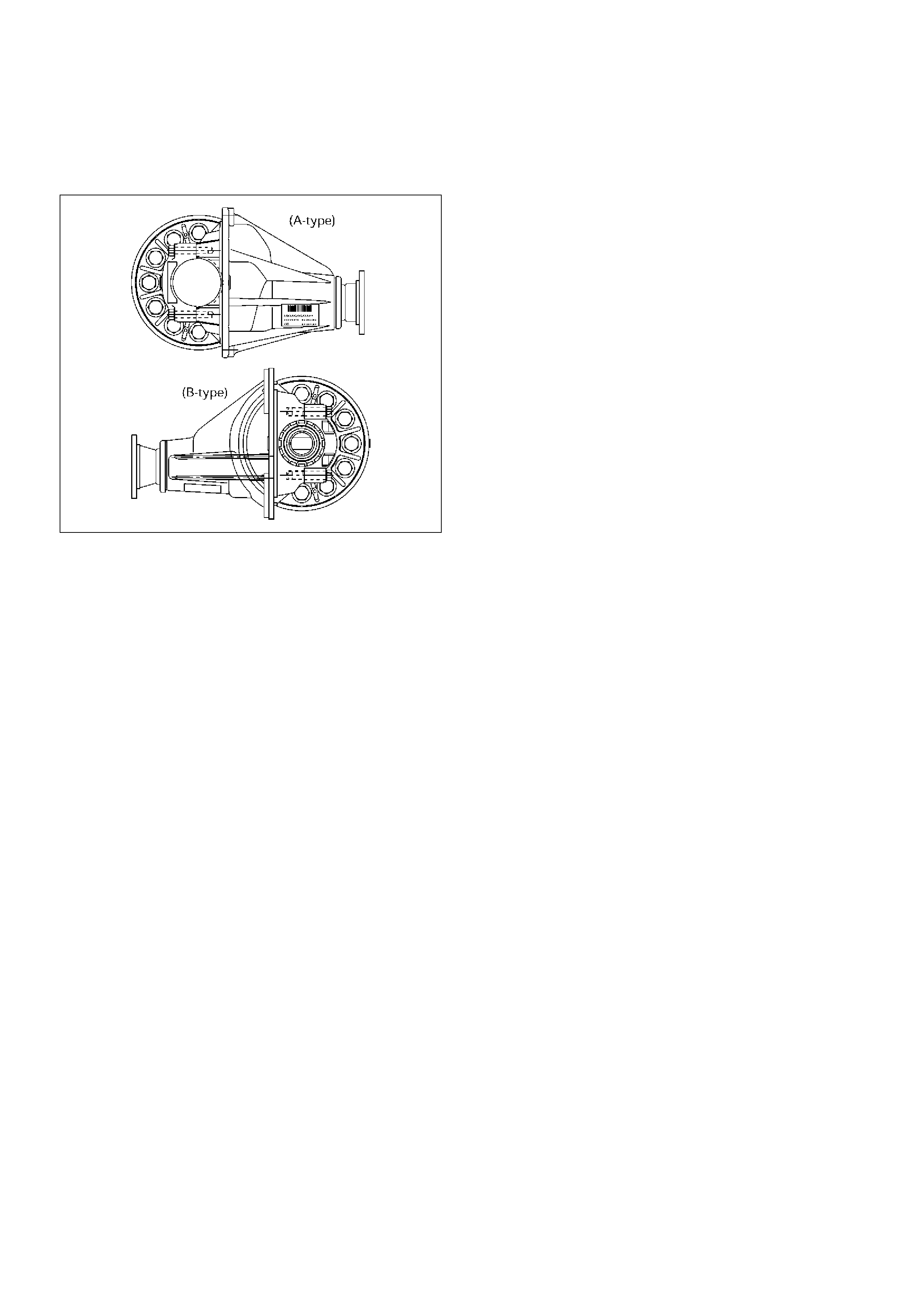
In case of Work Shop Manual;
A-type: Refer to '98 UBS Work Shop Manual.
B-type: Described in '00UBS Work Shop Manual.
425RY00018
General Description
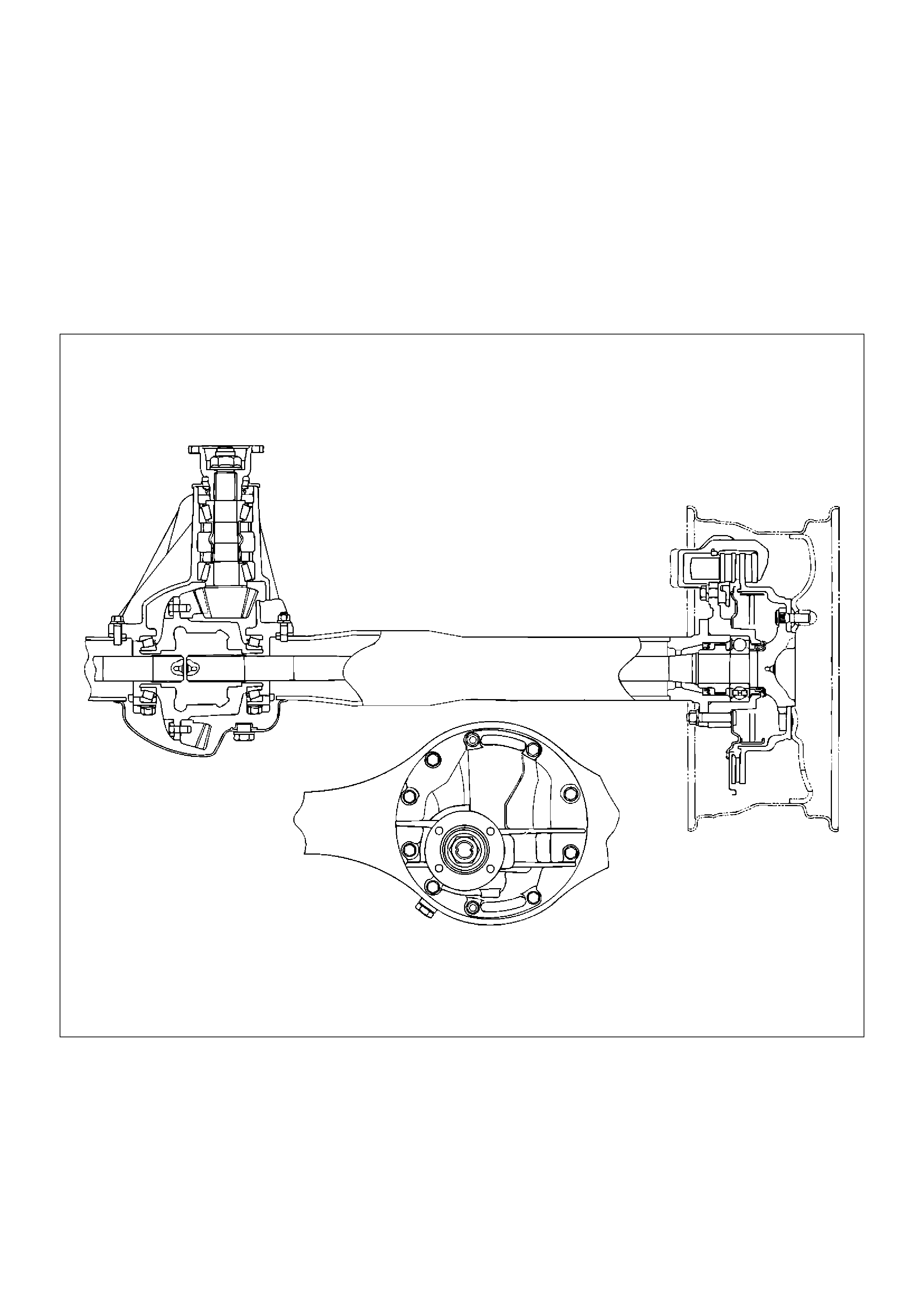
The rear axle assembly is of the semi–floating type in
which the vehicle weight is carried on the axle housing .
The center line of the pinion gear is below the center
line of the ring gear (hypoid drive).
All parts necessary to transmit power from the propeller
shaft to the rear wheels are enclosed in a banjo type
axle housing.
The 9.61 inch ring gear rear axle uses a conventional
ring and pinion gear set to transmit the driving force of
the engine to the rear wheels. This gear set transfers
this driving force at a 90 degree angle from the propeller
shaft to the drive shafts.
The axle shafts are supported at the wheel end of the
shaft by a roller bearing.
The pinion gear is supported by two tapered roller
bearings. The pinion depth is set by a shim pack located
between the gear end of the pinion and the roller
bearing that is pressed onto the pinion. The pinion
bearing preload is set by crushing a collapsible spacer
between the bearings in the axle housing.
420RY00006
The ring gear is bolted onto the differential cage with 12
bolts.
The differential cage is supported in the axle housing
by two tapered roller bearings. The differential and ring
gear are located in relationship to the pinion by using
selective shims and spacers between the bearing and
the axle housing. To move the ring gear, shims are
deleted from one side and an equal amount are added
to the other side. These shims are also used to preload
the bearings which are pressed onto the differential
cage. Two bearing caps are used to hold the differential
into the rear axle housing.
The differential is used to allow the wheels to turn at
different rates of speed while the rear axle continues to
transmit the driving force. This prevents tire scuffing
when going around corners and prevents premature
wear on internal axle parts.
The rear axle is sealed with a pinion seal, a seal at
each axle shaft end, and by a liquid gasket between the
differential carrier and the axle housing.

Diagnosis
Many noises that seem to come from the rear axle
actually originate from other sources such as tires, road
surface, wheel bearings, engine, transmission, muffler,
or body drumming. Investigate to find the source of the
noise before disassembling the rear axle. Rear axles,
like any other mechanical device, are not absolutely
quiet but should be considered quiet unless some
abnormal noise is present.
To make a systematic check for axle noise, observe the
following:
1. Select a level asphalt road to reduce tire noise and
body drumming.
2. Check rear axle lubricant level to assure correct
level, and then drive the vehicle far enough to
thoroughly warm up the rear axle lubricant.
3. Note the speed at which noise occurs. Stop the
vehicle and put the transmission in neutral. Run the
engine speed slowly up and down to determine if
the noise is caused by exhaust, muffler noise, or
other engine conditions.
4. Tire noise changes with different road surfaces; axle
noises do not. Temporarily inflate all tires to 344 kPa
(3.5kg/cm2,50 psi) (for test purposes only). This will
change noise caused by tires but will not affect
noise caused by the rear axle.
Rear axle noise usually stops when coasting at
speeds under 48 km/h (30 mph); however, tire noise
continues with a lower tone. Rear axle noise usually
changes when comparing pull and coast, but tire
noise stays about the same.
Distinguish between tire noise and rear axle noise
by noting if the noise changes with various speeds
or sudden acceleration and deceleration. Exhaust
and axle noise vary under these conditions, while
tire noise remains constant and is more pronounced
at speeds of 32 to 48 km/h (20 to 30 mph). Further
check for tire noise by driving the vehicle over
smooth pavements or dirt roads (not gravel) with the
tires at normal pressure. If the noise is caused by
tires, it will change noticeably with changes in road
surface.
5. Loose or rough front wheel bearings will cause
noise which may be confused with rear axle noise;
however, front wheel bearing noise does not change
when comparing drive and coast. Light application
of the brake while holding vehicle speed steady will
often cause wheel bearing noise to diminish. Front
wheel bearings may be checked for noise by jacking
up the wheels and spinning them or by shaking the
wheels to determine if bearings are loose.
6. Rear suspension rubber bushings and spring
insulators dampen out rear axle noise when
correctly installed. Check to see that there is no link
or rod loosened or metal–to–metal contact.
7. Make sure that there is no metal–to–metal contact
between the floor and the frame.
After the noise has been determined to be in the axle,
the type of axle noise should be determined, in order to
make any necessary repairs.
Gear Noise
Gear noise (whine) is audible from 32 to 89 km/h (20 to
55 mph) under four driving conditions.
1. Driving under acceleration or heavy pull.
2. Driving under load or under constant speed.
3. When using enough throttle to keep the vehicle
from driving the engine while the vehicle slows
down gradually (engine still pulls slightly).
4. When coasting with the vehicle in gear and the
throttle closed. The gear noise is usually more
noticeable between 48 and 64 km/h (30 and 40
mph) and 80 and 89 km/h (50 and 55 mph).
Bearing Noise
Bad bearings generally produce a rough growl or
grating sound, rather than the whine typical of gear
noise. Bearing noise frequently “wow–wows” at bearing
rpm, indicating a bad pinion or rear axle side bearing.
This noise can be confused with rear wheel bearing
noise.
Rear Wheel Bearing Noise
Rear wheel bearing noise continues to be heard while
coasting at low speed with transmission in neutral.
Noise may diminish by gentle braking. Jack up the rear
wheels, spin them by hand and listen for noise at the
hubs. Replace any faulty wheel bearings.
Knock At Low Speeds
Low speed knock can be caused by worn universal
joints or a side gear hub counter bore in the cage that is
worn oversize. Inspect and replace universal joints or
cage and side gears as required.
Backlash Clunk
Excessive clunk on acceleration and deceleration can
be caused by a worn rear axle pinion shaft, a worn
cage, excessive clearance between the axle and the
side gear splines, excessive clearance between the
side gear hub and the counterbore in the cage, worn
pinion and side gear teeth, worn thrust washers, or
excessive drive pinion and ring gear backlash. Remove
worn parts and replace as required. Select close–fitting
parts when possible. Adjust pinion and ring gear
backlash.
Axle Housing
Axle Housing and Associated Parts
420RY00007
EndOFCallout
Removal
1.Raise the vehicle and support it with suitable safety
stands.
The hoist must remain under the rear axle housing.
2.Drain brake fluid. Refer to Hydraulic Brakes in
Brakes section.
3.Remove rear wheels and tires. Refer to Wheel in
Suspension section.
4.Remove propeller shaft. Refer to Rear Propeller
Shaft in this section.
5.Drain the rear axle oil into a proper container.
6.Remove parking brake cable, release the
connection between the cable fixing clip equalizer.
Refer to Parking Brakes in Brakes section.
7. Move the clip aside and pull out the breather hose.
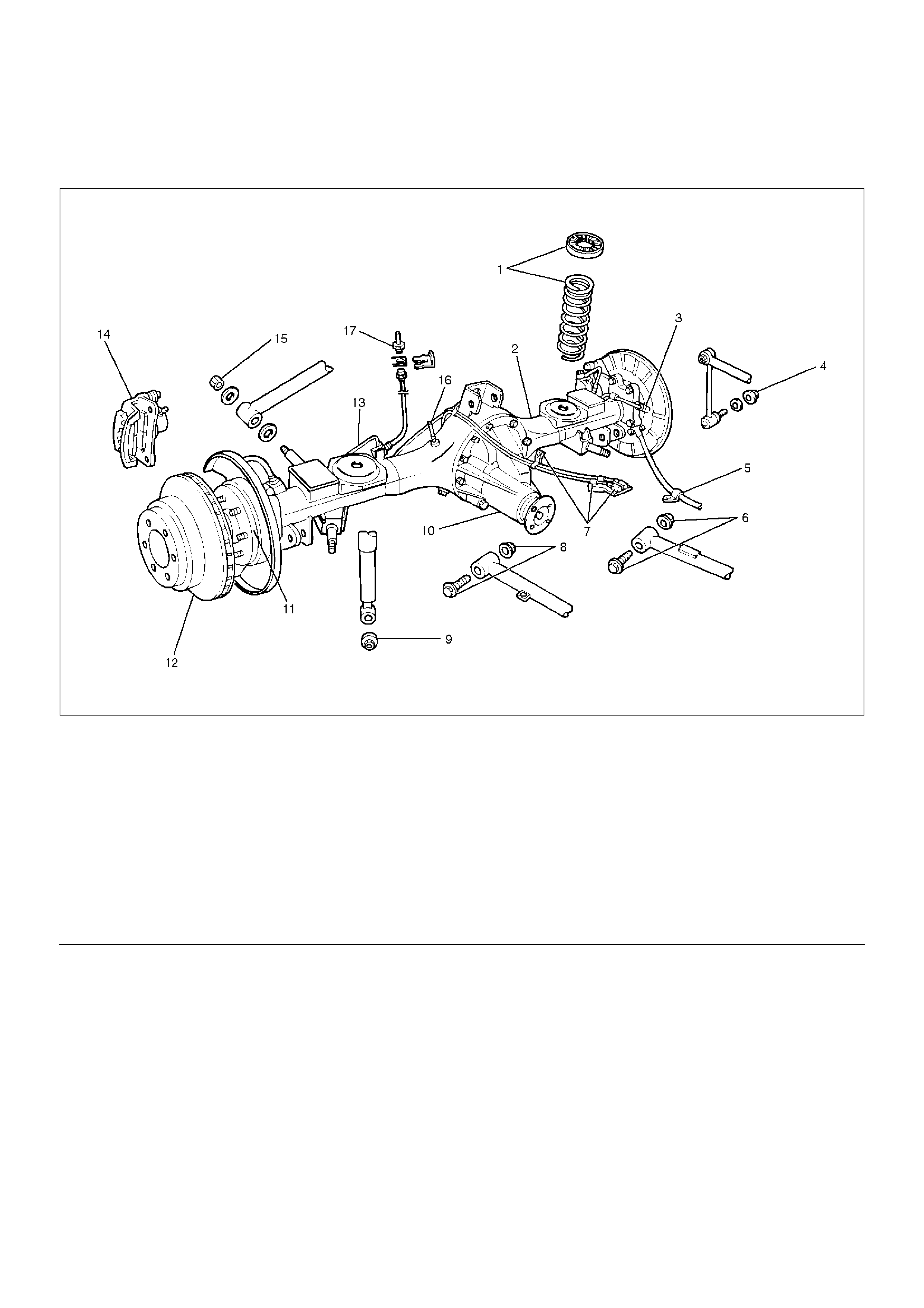
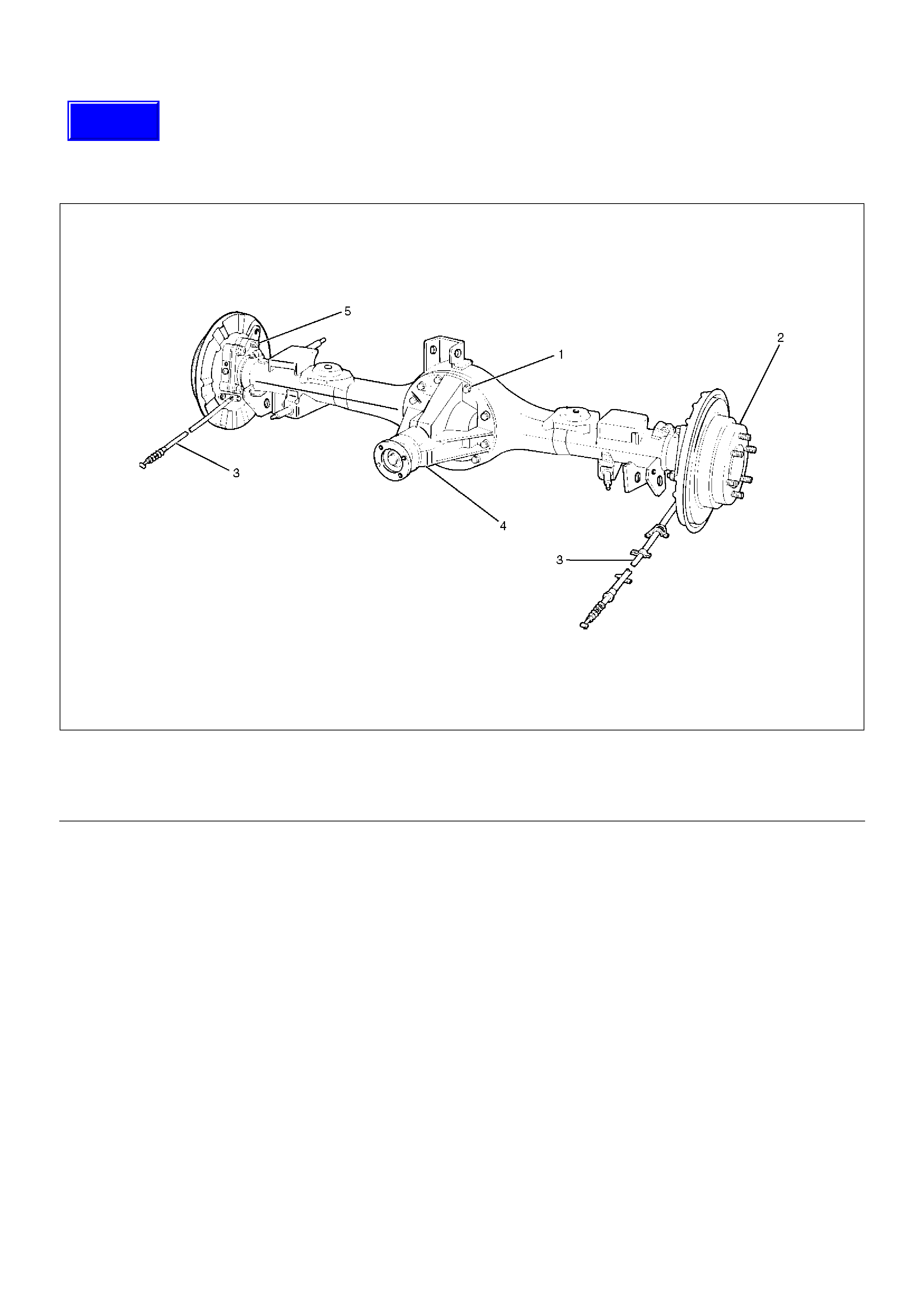
Legend
(1) Coil Spring and Insulator
(2) Axle Housing Assembly
(3) ABS Speed Sensor and Harness (if so
equipped)
(4) Nut
(5) Parking Brake Cable
(6) Bolt and Nut
(7) Antilock Brake System (ABS) Connector and
Bracket (if so equipped)
(8) Bolt and Nut
(9) Nut
(10) Differential Assembly
(11) Axle Shaft Assembly
(12) Brake Disc
(13) Brake Pipe
(14) Brake Caliper
(15) Nut
(16) Breather Hose
(17) Flare Nut
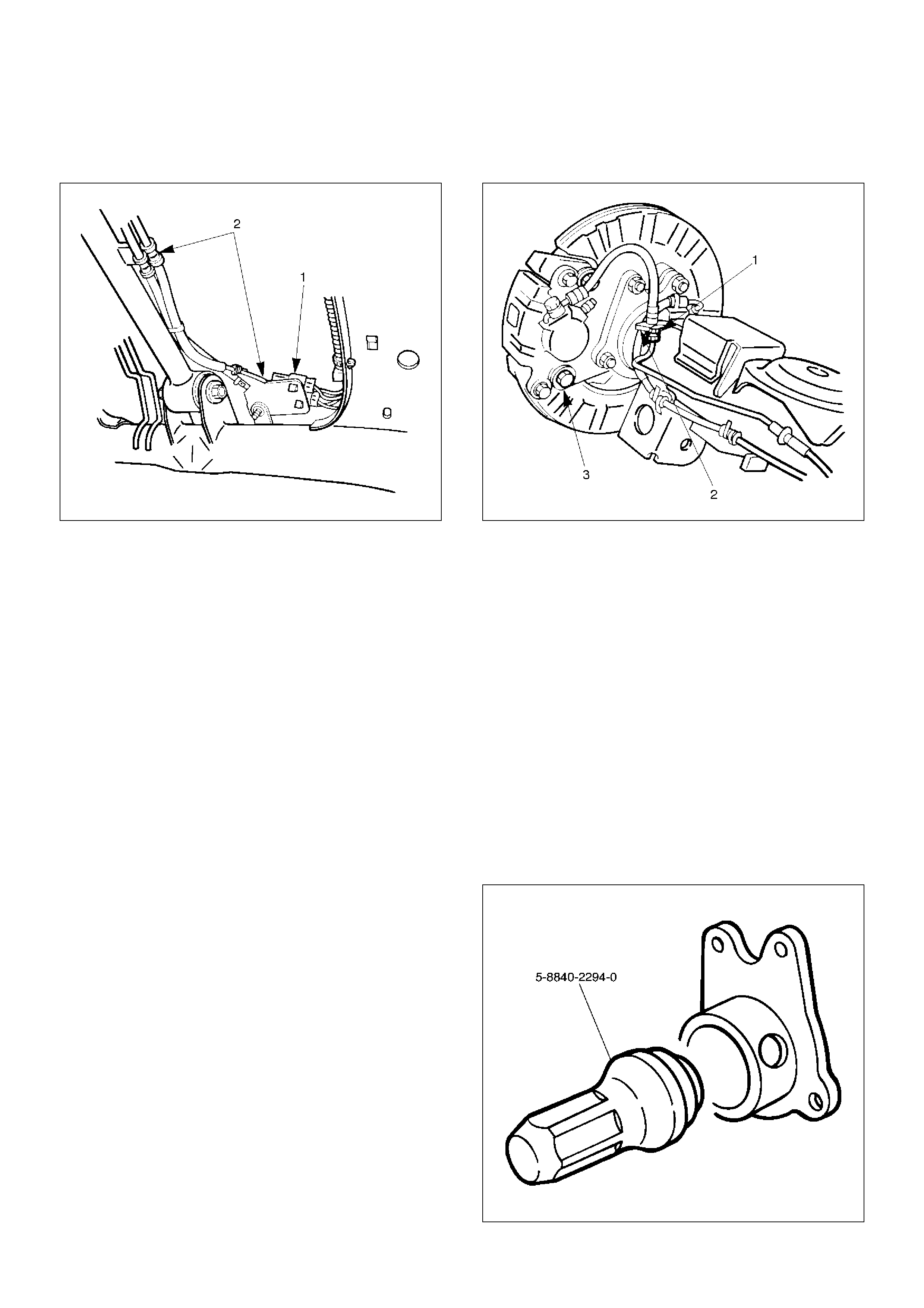
8.Disconnect the ABS connectors (1) and remove the
brackets (2) (if so equipped) attached to the frame
and center link.
350RS001
9.Loosen the brake tube flare nut, remove the clip and
take out the brake tube.
10.Remove the shock absorber fixing nut from the axle
housing.
11.Remove the stabilizer linkage mounting nut from the
axle housing.
12.Remove the lateral rod fixing nut from the axle
housing.
13.Remove the center link mounting bolt and nut from
the axle housing.
14.Remove the trailing link fixing bolt and nut from the
axle housing.
15.Jack down and remove the coil spring and insulator.
16.Axle housing assembly can be separated from the
vehicle on completion of steps 1 – 11.
17. Remove the brake caliper fixing bolt (3), loosen the
flare nut (1), release the clip (2) and take out the
brake caliper together with the flexible hose.
306RS001
18.Remove brake disc.
19.Remove antilock brake system speed sensor fixing
bolt and the clip and bracket (if so equipped) on the
axle housing.
20.Remove the brake pipe clip and fixing bolt on the
axle housing and take out the brake pipe.
21.Remove the bearing holder fixing nut and take out
the axle shaft assembly, be sure not to damage the
oil seal by the spline of the shaft, Refer to Axle Shaft
in this section.
22.Remove differential assembly, refer to Differential
Assembly in this section.
Oil Seal Replacement
Remove the oil seal, carefully not to damage the
housing, and mount new oil seal using oil seal installer
5–8840–2294–0
420RW028

Installation
1.Install differential assembly, refer to Differential
Assembly in this section.
2.Install axle shaft assembly then tighten the bearing
holder mounting nut to the specified torque. Be sure
not to damage the oil seal by the spline of the shaft.
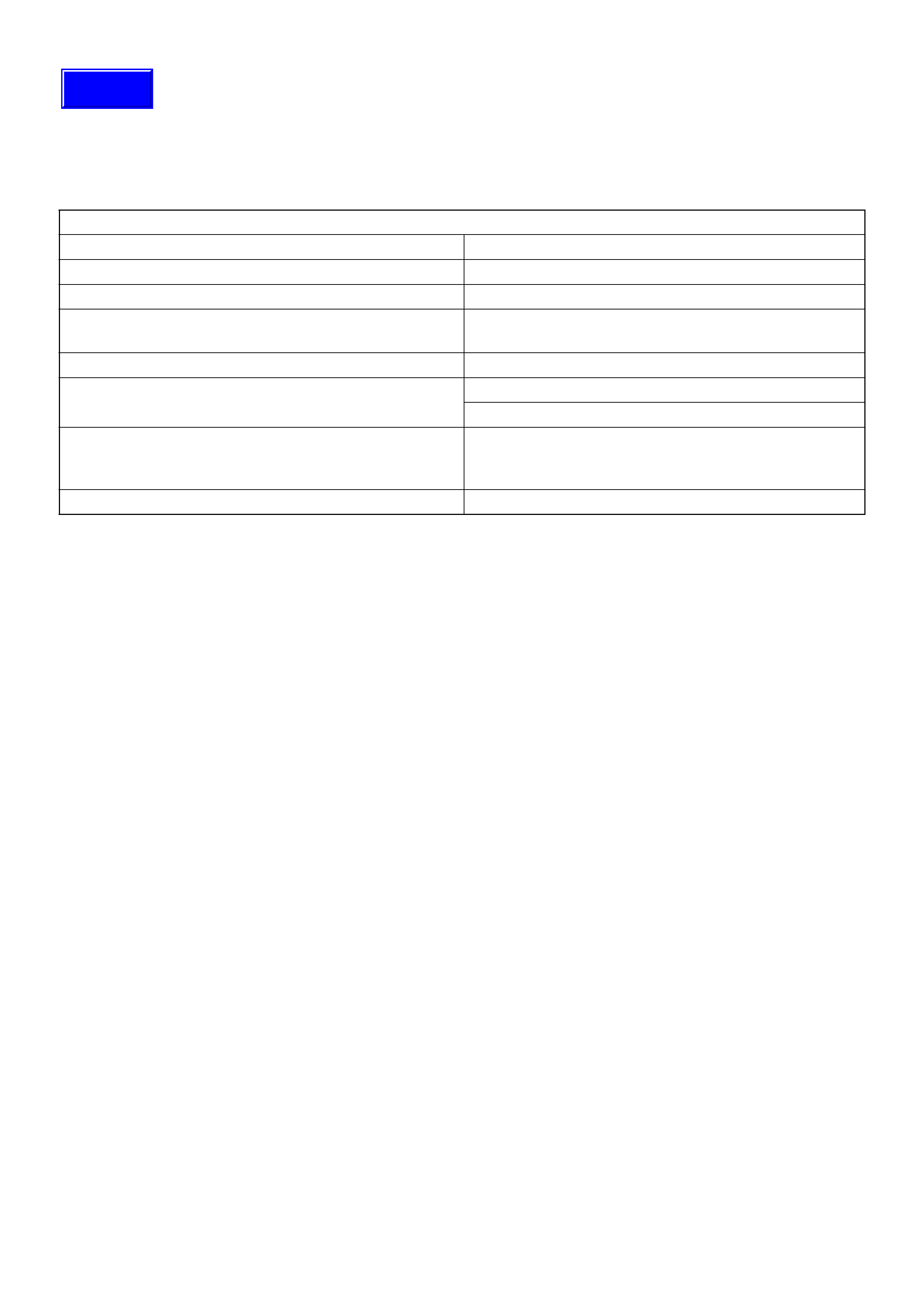
Torque: 74N·m (7.5kg·m/54lbft)
3.Install brake pipe.
4.Connect antilock brake system (ABS) speed sensor
and harness (if so equipped), refer to Anti–Lock
Brake System in Brake section.
5.Install brake disc.
6.Install brake caliper. Refer to Disc Brakes in Brake
section.
7.Install axle housing assembly.
8.Install coil spring and insulator.
9. Install the trailing link fixing bolt and nut to the axle
housing. For the procedures in items 9–13, refer to
Suspension section.
10.Install the center link bolt and nut to the axle
housing.
11.Install the lateral rod fixing nut to the axle housing.
12.Install the stabilizer linkage mounting nut to the axle
housing.
13.Install the shock absorber fixing nut to the axle
housing.
14.Install brake tube flare nut, Refer to Disc Brakes in
Brake section.
15.Install ABS connector and bracket (if so equipped).
16.Connect breather hose.
17.Install parking brake cable, Refer to Parking Brakes
in Brake section.
18.Bleed brakes. Refer to Hydraulic Brakes in Brake
section.
Axle Shaft
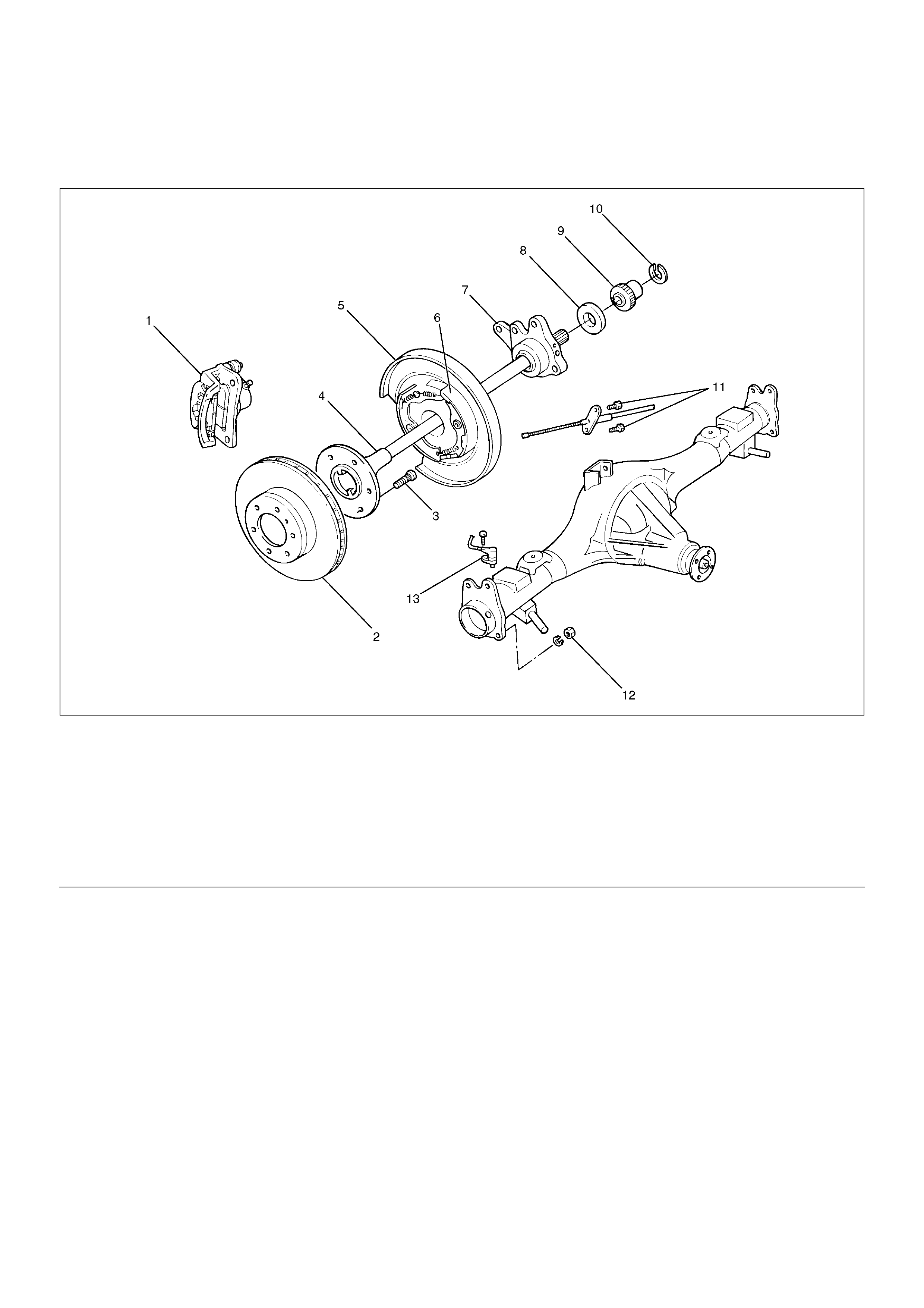
Axle Shaft and Associated Parts
420RY00005
EndOFCallout
Removal
1.Raise the vehicle.
2.Remove tires and wheels. Refer to Wheel in
Steering section.
3. Remove brake caliper. Use a wire to attach the
brake caliper to the frame. Refer to Disc Brakes in
Brake section.
4. Remove brake disc.
5. Remove ABS sensor.
6.Remove Parking brake assembly. Refer to Parking
Brakes in Brake section.
Legend
(1) Brake Caliper
(2) Brake Disc
(3) Wheel Pin
(4) Axle Shaft Assembly
(5) Back Plate
(6) Parking Brake Assembly
(7) Bearing Holder
(8) Bearing
(9) Retainer
(10) Snap Ring
(11) Bolt
(12) Nut
(13) Antilock Brake System (ABS) Speed Sensor
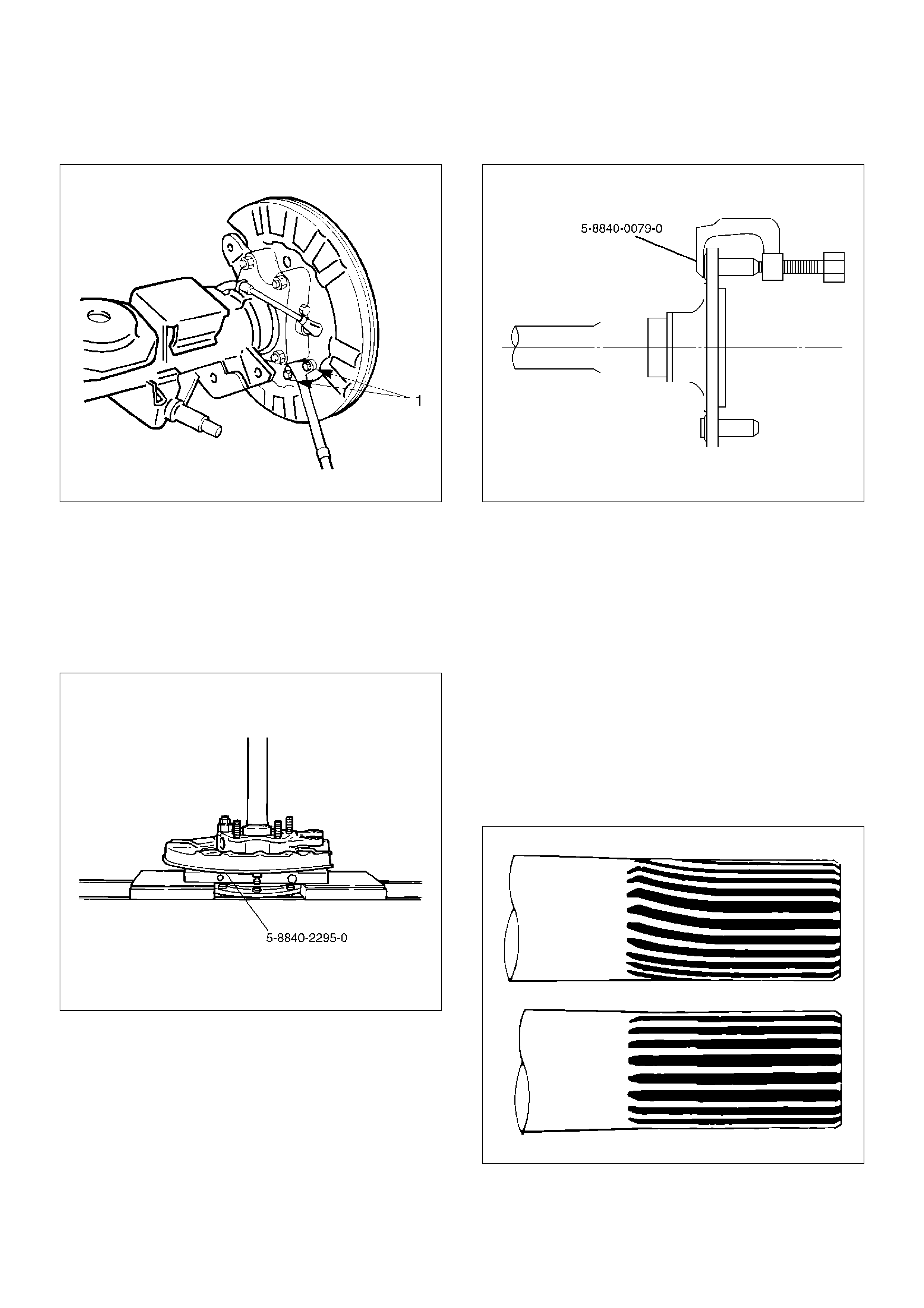
7. Remove the parking brake cable mounting
bolts(Behind the back plate)(1).
311RS001
8. Remove the bearing holder mounting nuts.
9. Remove axle shaft assembly.
NOTE: Be sure not to damage the oil seal.
10. Remove snap ring.
11. Using a bearing remover 5–8840–2295–0 and
press, remove retainer together with the bearing
holder.
420RY00012
12. Remove bearing.
13. Remove bearing holder.
14. Remove back plate.
15. Remove the wheel pins using a remover 5–8840–
0029–0.
420RY00011
Inspection and Repair
Make necessary correction or parts replacement if
wear, corrosion or any other abnormal conditions are
found through inspection.
Visual Check:
Check the following parts for wear, damage, noise or
any other abnormal conditions:
1. Axle shaft
2. Bearing
When checking the axle shaft, pay special attention to
the splined portions and replace the shaft if distortion or
step wear is noticeable. Correct slight step wear with a
grinder.
420RS008
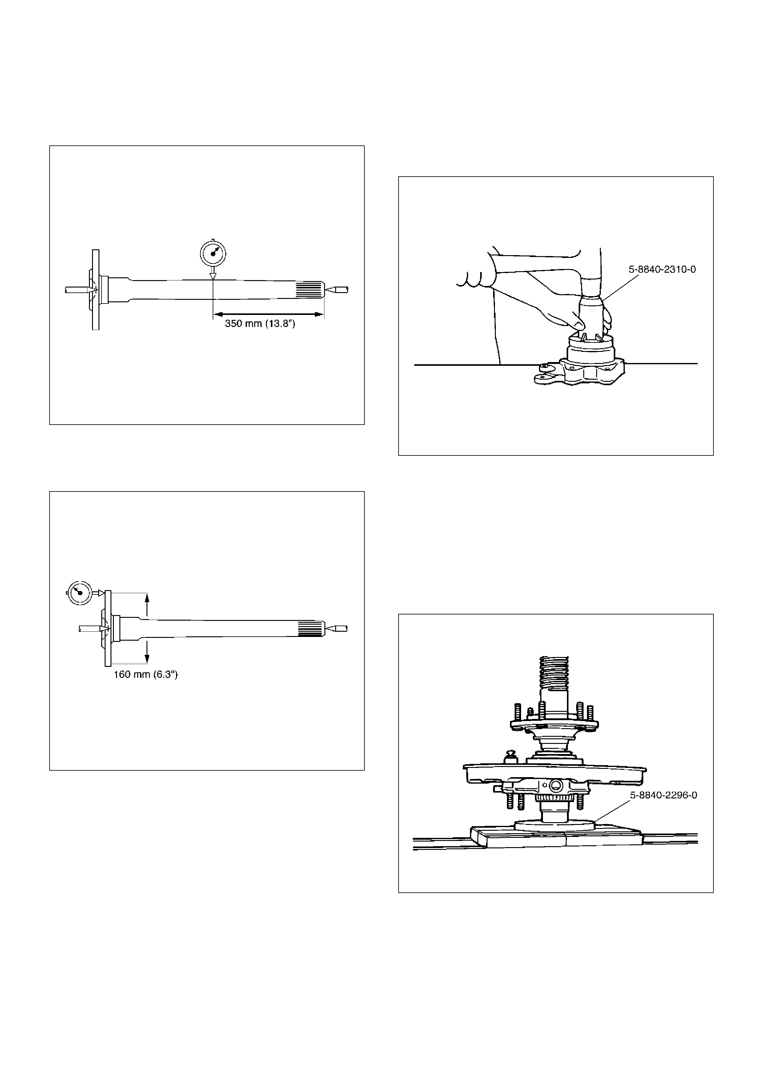
Axle Shaft Run–out
Limit: 1.0 mm (0.039 in)
420RS009
Axle Shaft Flange Run–out
Limit: 0.08 mm (0.003 in)
420RS010
Oil Seal Replacement
Remove the oil seal carefully not to damage the bearing
holder bore .
When installing, use oil seal installer 5–8840–2310–0.
420RY00009
Installation
1. Install wheel pin.
2. Install back plate.
3. Install bearing holder.
4. Install bearing.
5. Install retainer by using a bearing installer 5–8840–
2296–0, press fit together with the bearing.
420RY00010
6.Install snap ring.
7.Install axle shaft assembly.
NOTE: Be sure not to damage the oil seal.
8.Tighten the bearing holder mounting nut to the
specified torque.
Torque: 74N·m (54 Ib ft)
9.Fix the parking brake cable mounting bolt (Behind
the back plate).
10.Install parking brake assembly, refer to Parking
Brakes in Brake section.
11.Install antilock brake system sensor.
12.Install brake disc.
13.Install brake caliper, refer to Disc Brakes in Brake
section.
Pinion Oil Seal
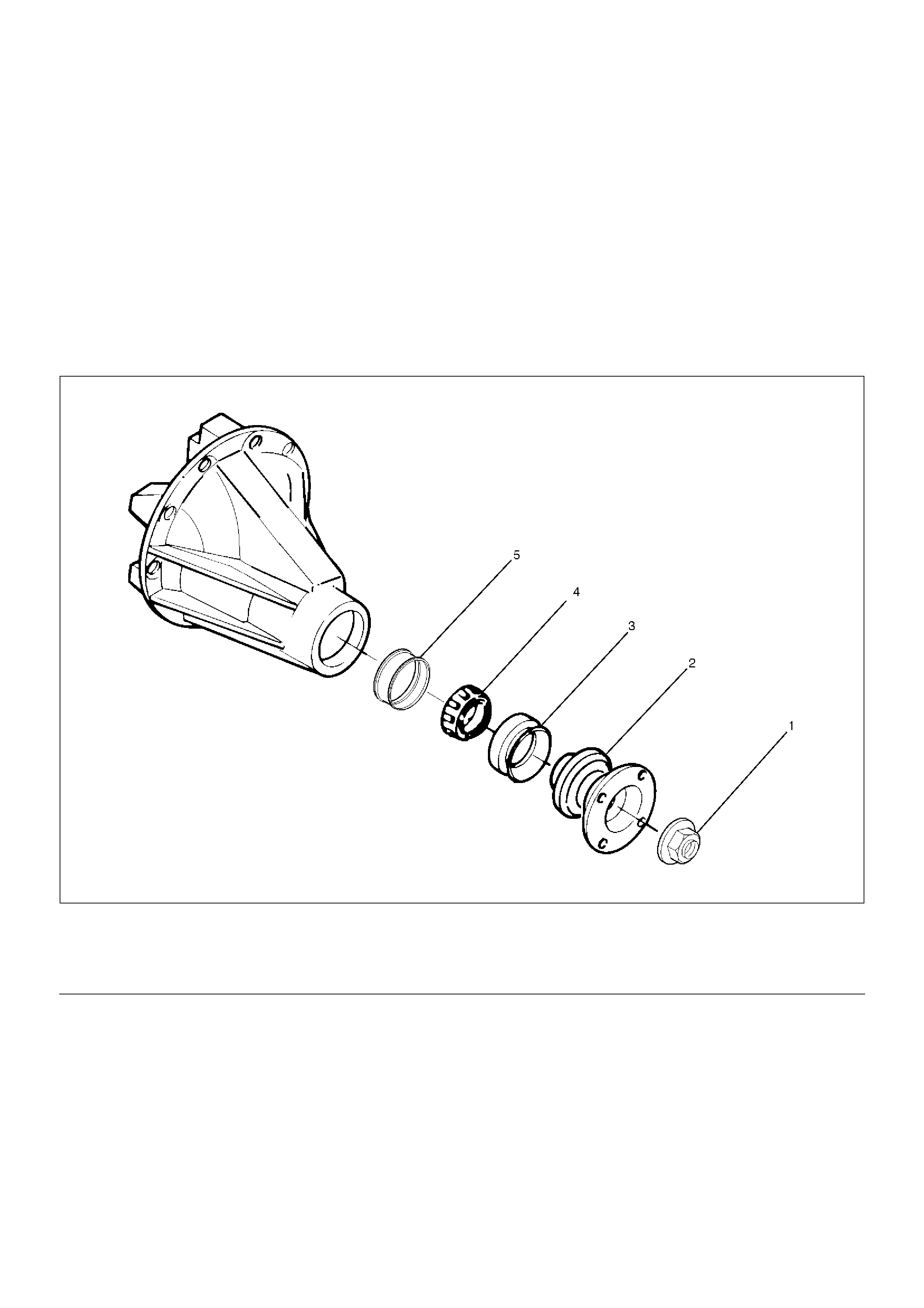
Pinion Oil Seal and Associated Parts
425RY00010
EndOFCallout
Removal
1.Remove the rear propeller shaft. Refer to Rear
Propeller Shaft in this section.
2. Drain the rear axle oil.
Legend
(1) Flange Nut and Washer
(2) Flange
(3) Oil Seal
(4) Outer Bearing
(5) Collapsible Spacer
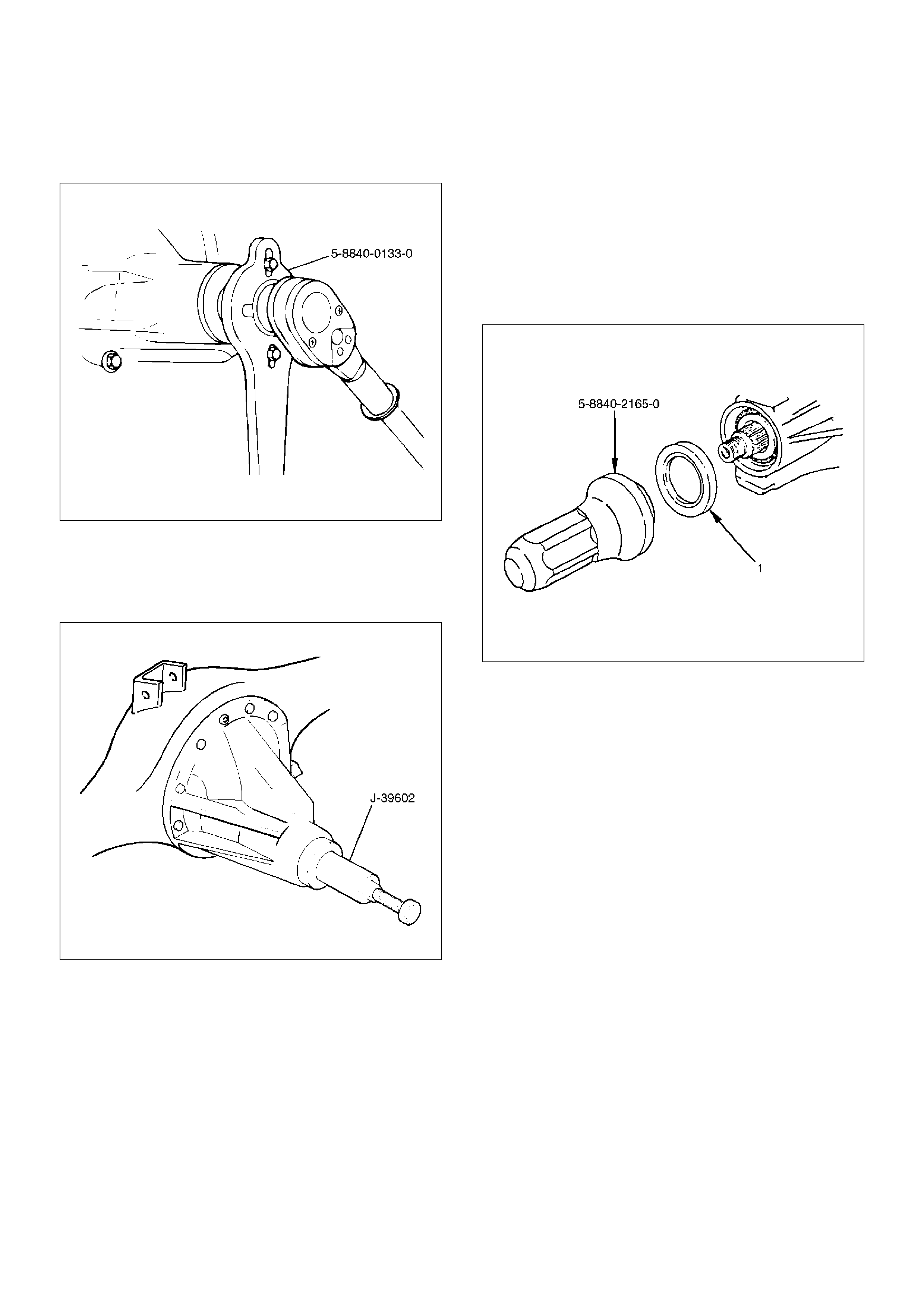
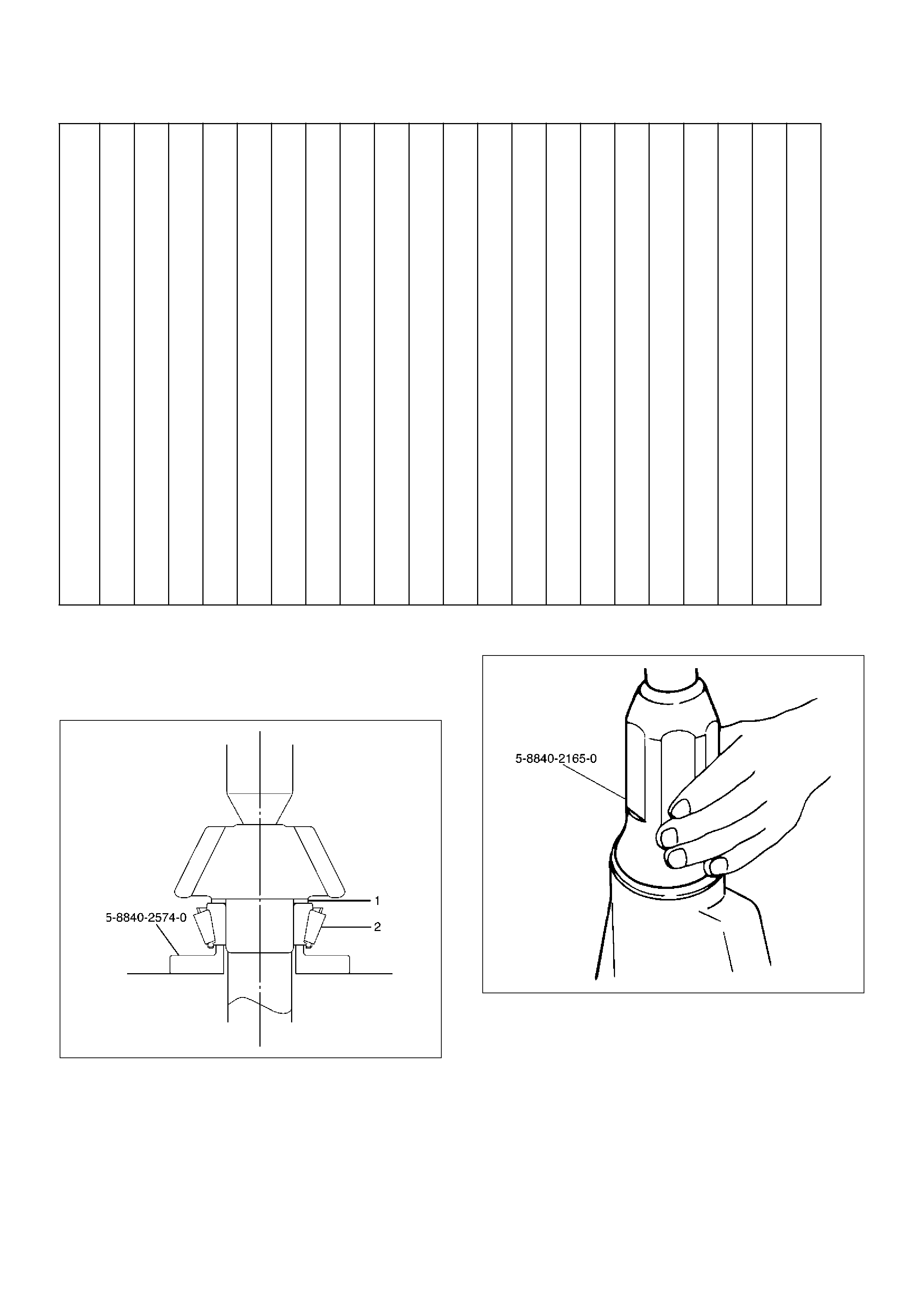
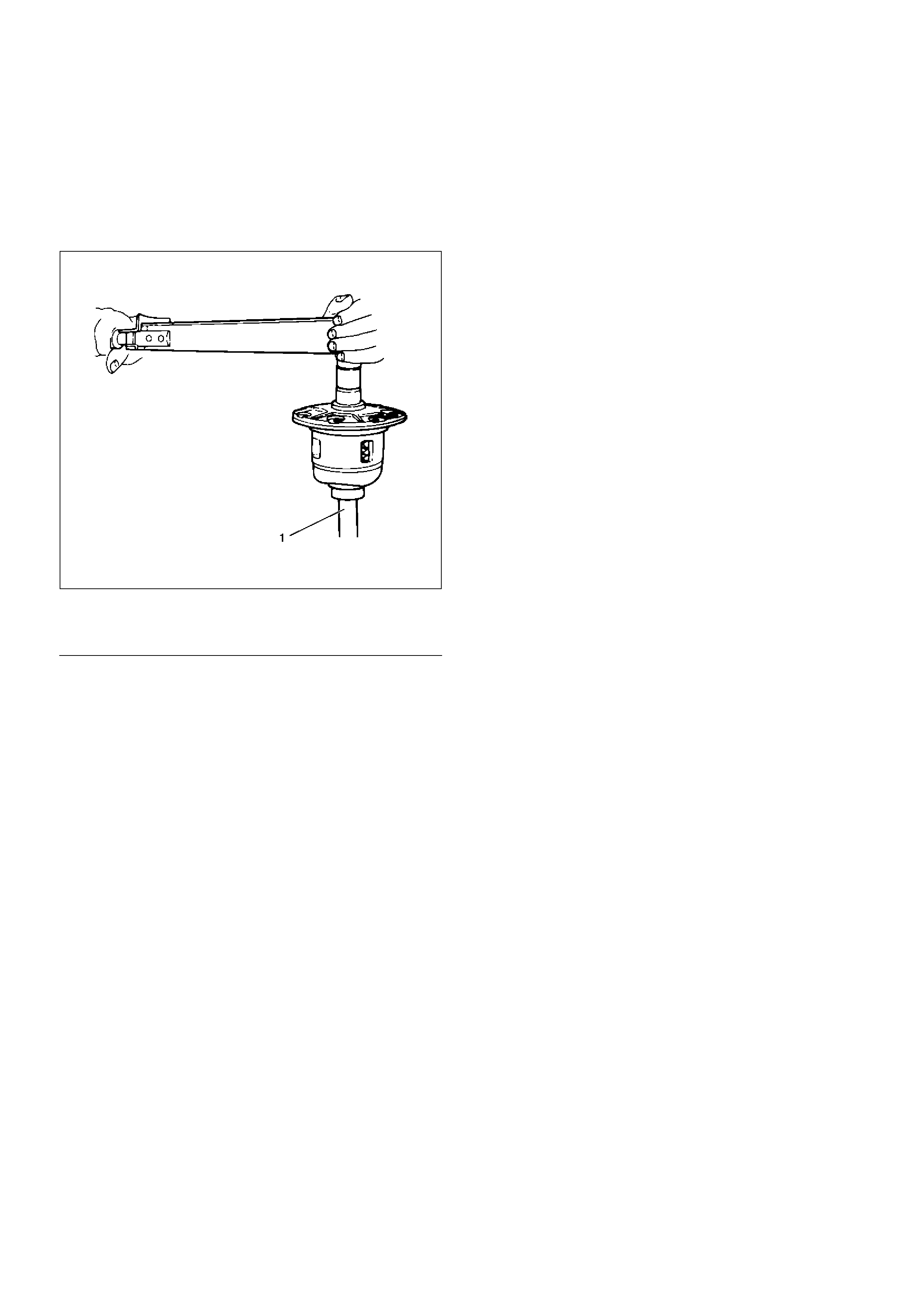
3.Remove flange nut and washer by using pinion
flange holder 5–8840–0133–0 after raising up its
staked parts completely.
415RW040
4.Remove flange.
5.Remove oil seal.
6.Remove outer bearing by using remover 5–8840–
2323–0.
425RY00003
7.Remove collapsible spacer.
Inspection and Repair
Make necessary correction or parts replacement if wear,
damage, corrosion or any other abnormal conditions are
found through inspection.
Check the following parts:
1.Seal surface of the pinion.
2.Cage bore for burns.
Installation
1.Install collapsible spacer, discard the used
collapsible spacer and install a new one.
2.Install outer bearing.
NOTE: Do not drive in, but just temporarily set in the
outer bearing by hand, which should be indirectly
pressed in finally by tightening the flange nut.
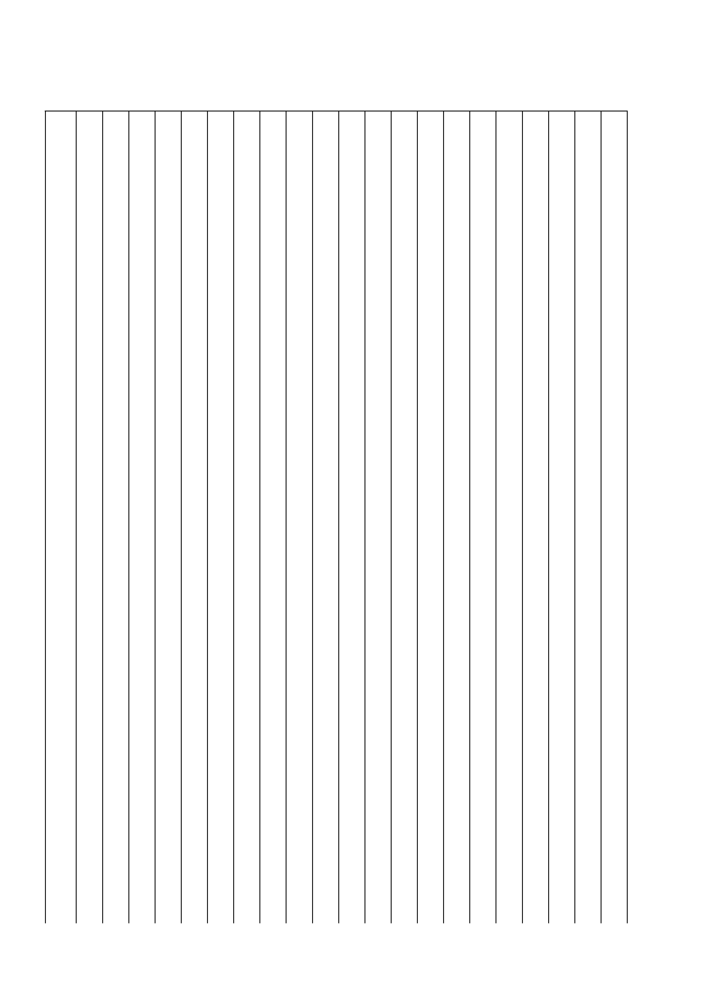
3.By using the seal installer 5–8840–2165–0, install a
new oil seal (1) that has grease on seal lip.
425RW050
4.Install flange.
5.Install flange nut and washer. Refer to Differential
Assembly in this section for flange nut reassembly.
NOTE: Discard the used nut and install a new one.
Differential Assembly
Differential Assembly and Associated Parts
425RY00016
EndOFCallout
Removal
1.Jack up and support the frame with stands.
2.Remove the wheel and tire. Refer to Wheel in
Steering section.
3. Drain the differential oil.
4.Remove the propeller shaft. Refer to Rear Propeller
Shaft in this section.
5.Remove the ABS speed sensor. Refer to Anti–lock
Brake System in Brakes section.
6. Remove the parking brake cable fastening clip and
disconnect the equalizer section. Refer to Parking
Brakes in Brake section.
7. Remove the bearing holder fixing nuts.
8. Remove axle shaft assembly, be sure not to
damage the oil seal by axle shaft.
9. Remove differential carrier mounting bolts and nuts.
10. Remove differential assembly.
Legend
(1) Bolt and Nut
(2) Axle Shaft Assembly
(3) Parking Brake Cable
(4) Differential Assembly
(5) Nut
Techline
Installation
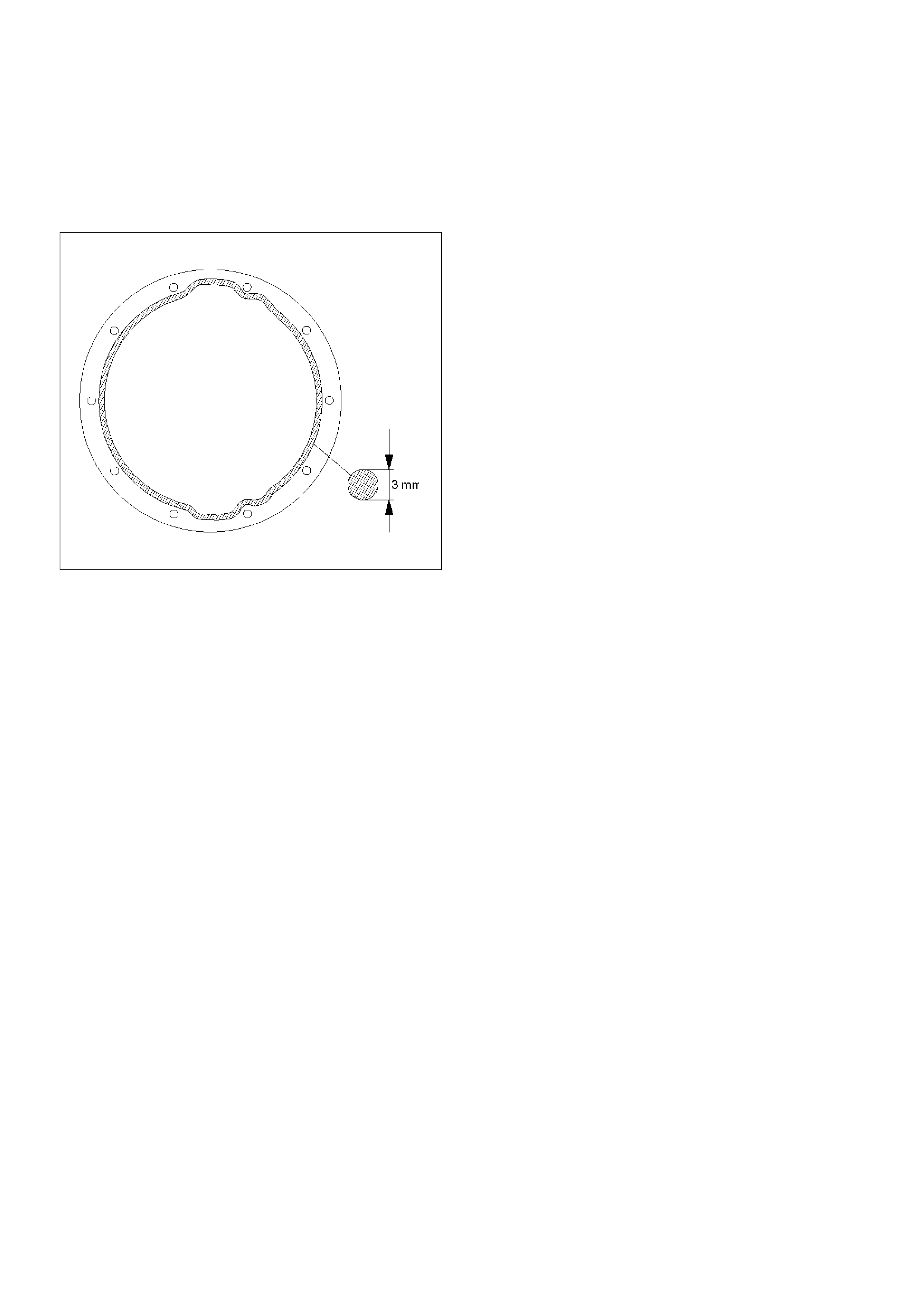
1. Clean the contact surfaces of the axle and
differential carrier. As shown in the drawing, apply
Three Bond TB1215 or equivalent then install
differential assembly.
425RS006
2. Install bolt and nut. Tighten the differential carrier
mounting bolts and nuts to the specified torque.
Torque:Nuts 44N·m (4.5kg·m/33lbft)
Bolts 64N·m (6.5kg·m/47lbft)
3. Install axle shaft assembly. Be sure not to damage
the oil seal by axle shaft.
4. Install nut, refer to Axle Shaft in this section.
5. Install parking brake cable, refer to Parking Brakes
in Brake section.
NOTE: After completing the assembling work, fill the
prescribed gear oil to the filler hole.
Lubricant capacity: 3.0 liter (2.6Impqt/3.2 USqt)
6. Tighten the oil filler plug to the specified torque.
Torque: 78N·m (8.0kg·m/58lbft)
Disassembled View
415RY00002
EndOFCallout
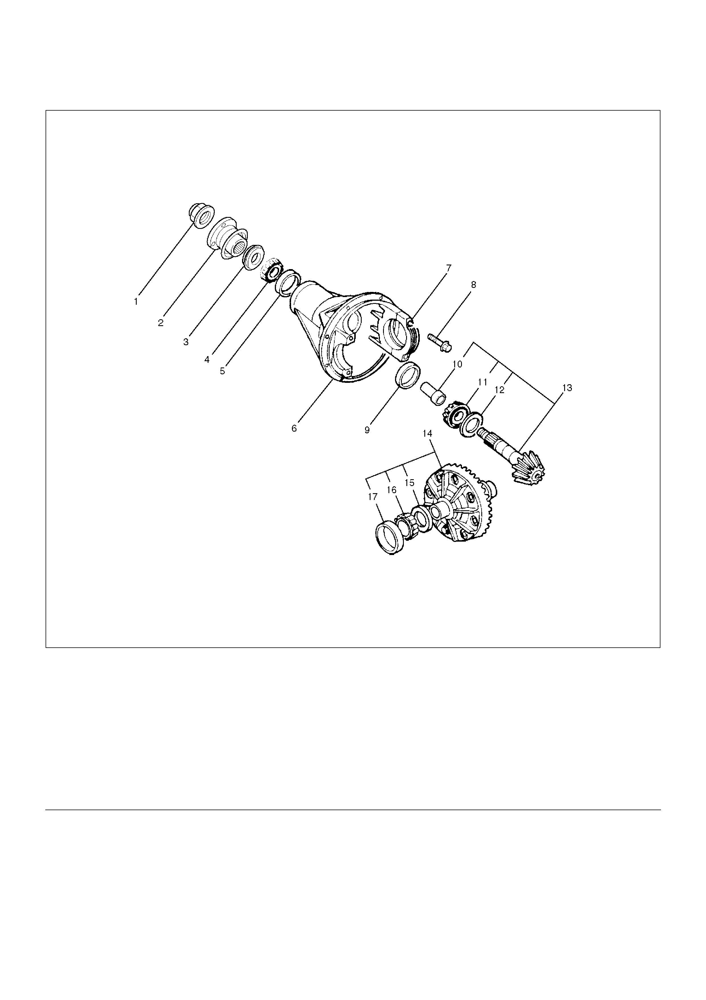
Legend
(1) Flange Nut and Washer
(2) Flange
(3) Oil Seal
(4) Outer Bearing
(5) Outer Bearing Outer Race
(6) Diff Carrier
(7) Bearing Cap
(8) Bolt
(9) Inner Bearing Outer Race
(10) Collapsible Spacer
(11) Inner Bearing
(12) Adjust Shim (Pinion Position)
(13) Drive Pinion Shaft
(14) Adjust Shim (Diff Cage Assembly)
(15) Diff Preload/Backlash
(16) Side Bearing
(17) Side Bearing Outer Race
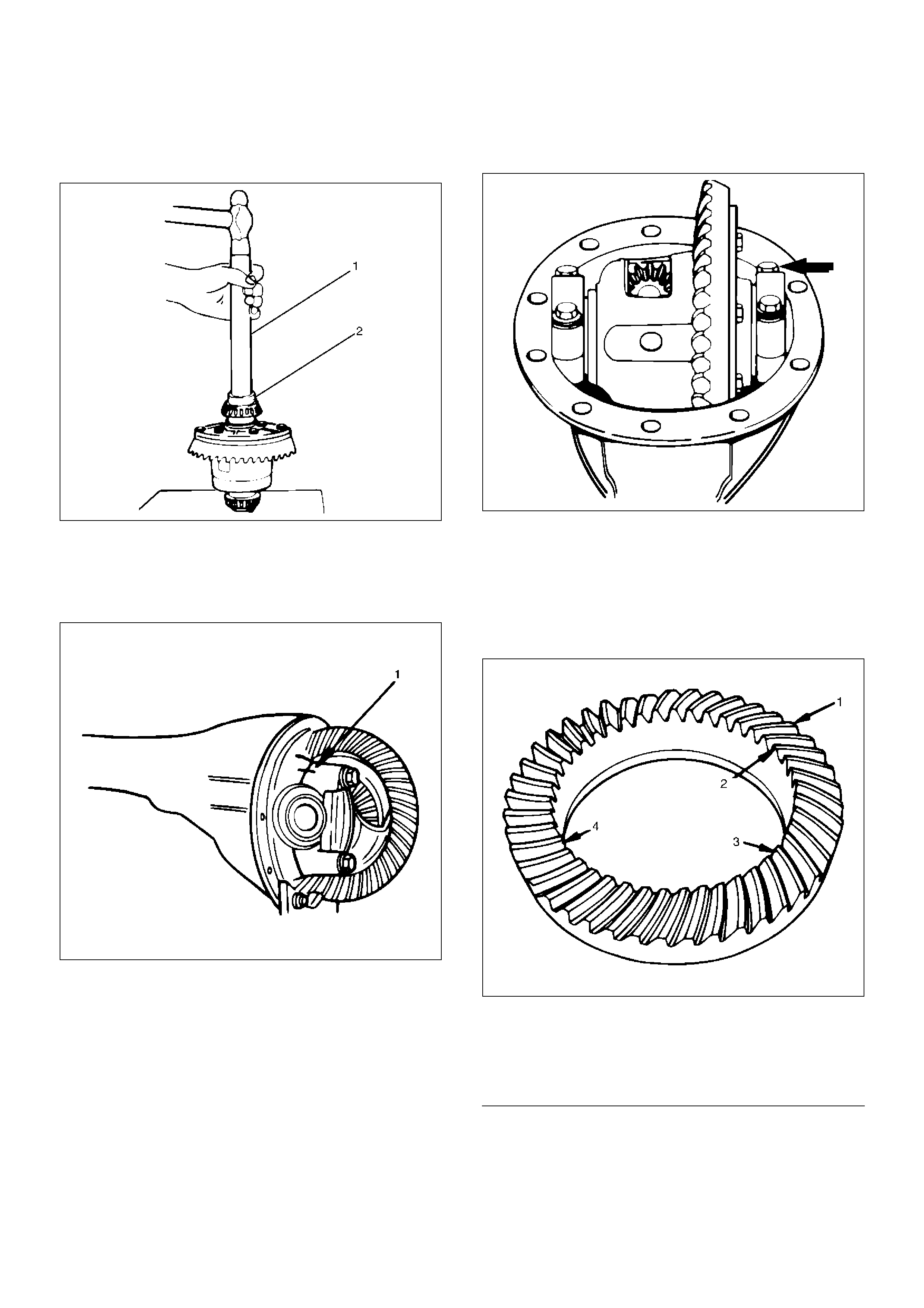
Disassembly
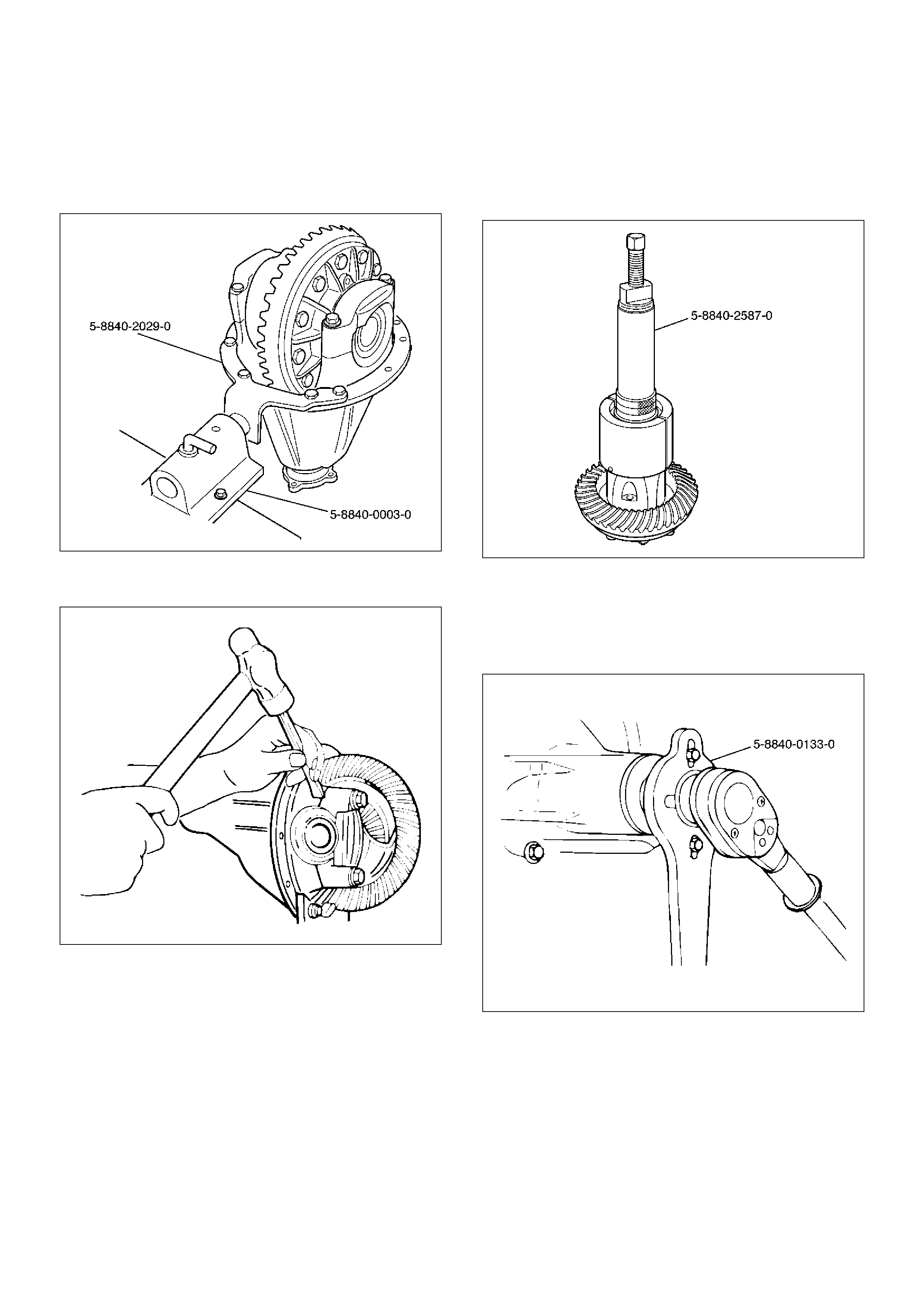
1. Using holding fixture 5–8840–2029–0 and holding
fixture base 5–8840–0003–0, fix the differential
assembly to the bench.
425RW058
2. Apply a setting mark to the side bearing cap and the
differential carrier then remove bearing cap.
425RS009
3. Remove differential cage assembly.
4. Remove side bearing outer race. After removal,
keep the right and left hand side bearing assemblies
separate to maintain inner and outer race
combinations.
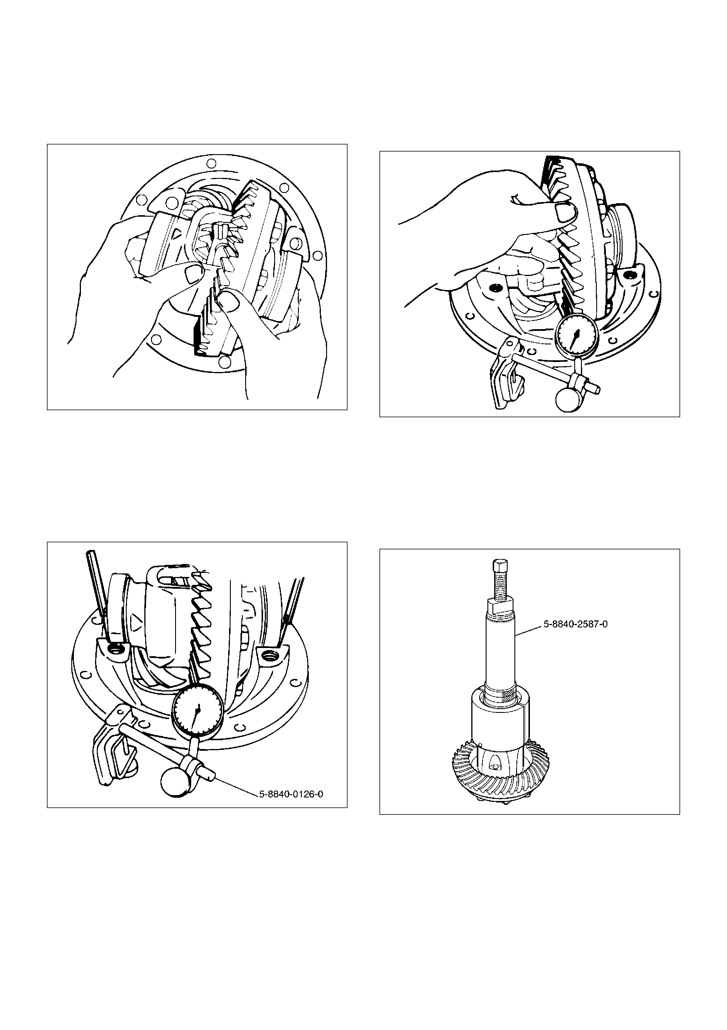
5. Remove side bearing by using remover 5–8840–
2587–0 and adapter 5–8840–2576–0. Select collet
halves 44803 in remover kit 5–8840–2587–0 for
side bearing removal and insert is not required for
this operation.
415RW041
6. Note the thickness and position of the shims then
remove adjust shim.
7. Remove the flange nut and washer by using pinion
flange holder 5–8840–0133–0 after raising up its
staked parts completely.
415RW040
8. Removed flange assembly.
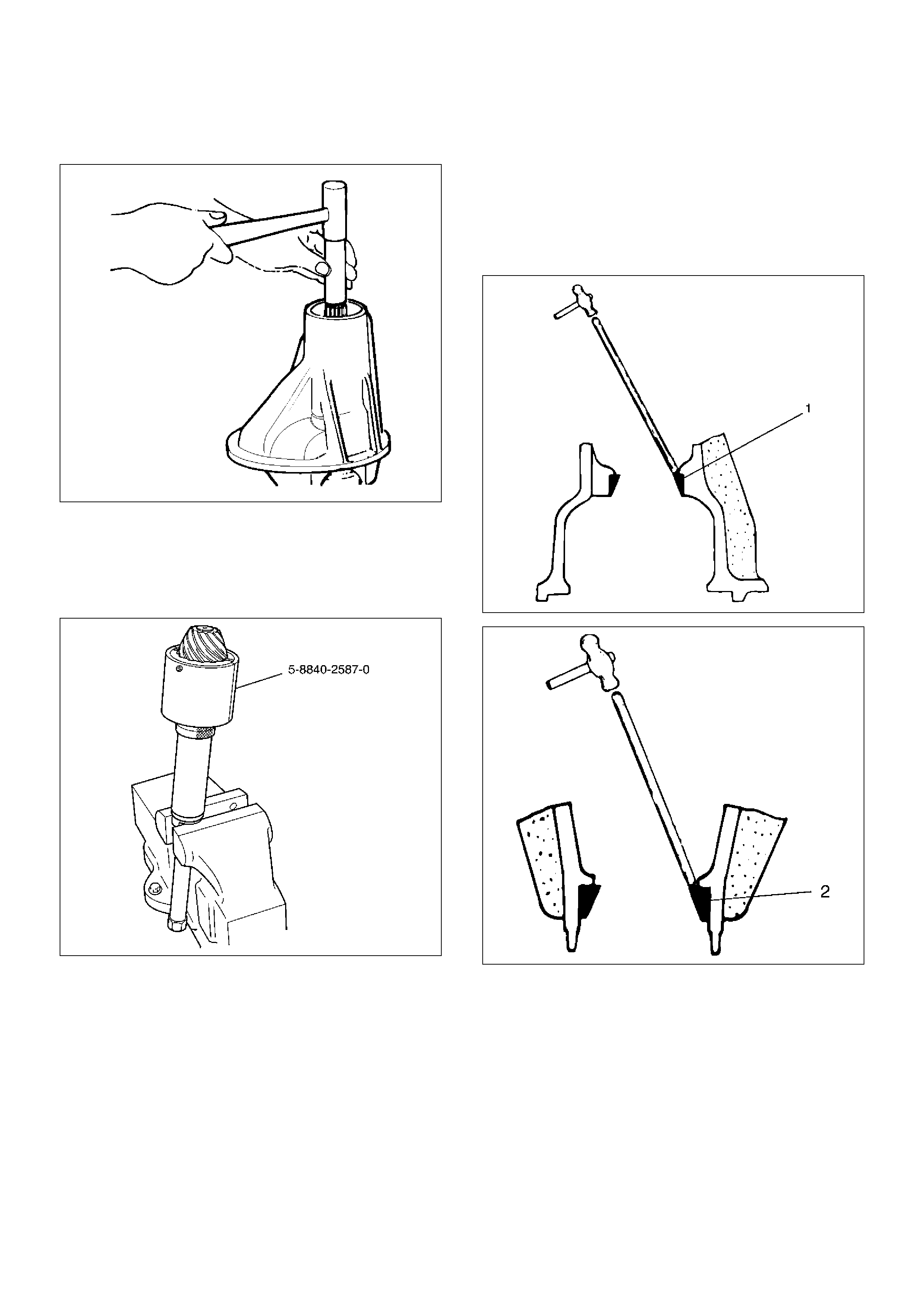
9. Remove the drive pinion assembly using a soft
metal rod and a hammer.
425RY005
10. Remove collapsible spacer.
11. Remove the inner bearing by using remover 5–
8840–2587–0. Select insert 303174 and collet
halves 44803 in remover kit 5–8840–2587–0 for
inner bearing removal.
415RW042
12. Remove adjust shim.
13. Remove oil seal.
14. Remove oil seal slinger.
15. Remove outer bearing.
16. Remove the inner bearing outer race (1) and the
outer bearing outer race (2) by using a brass bar
and a hammer.
425RS014
425RS015
Reassembly
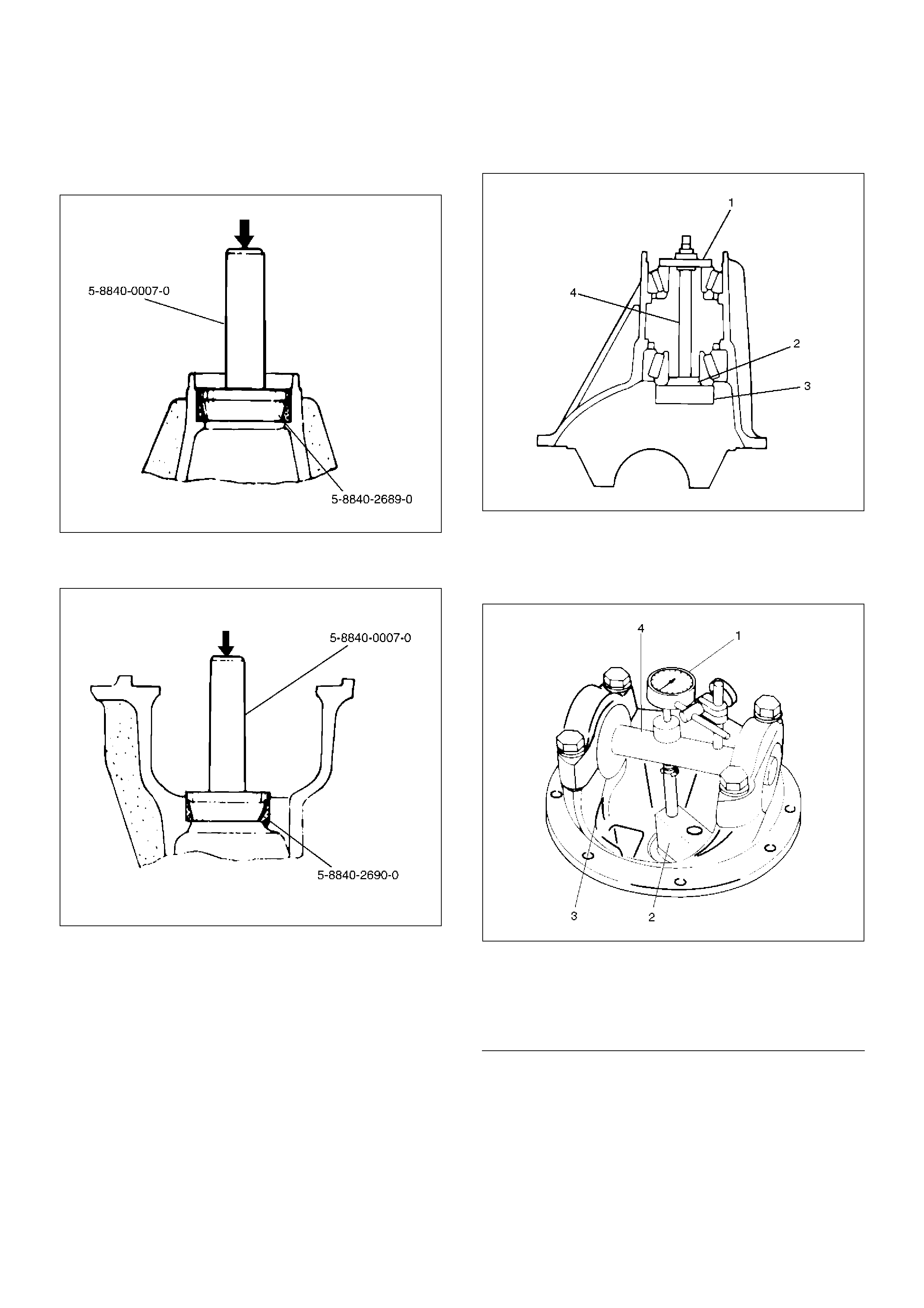
1. Install outer bearing outer race by using installer 5–
8840–2689–0 and grip 5–8840–0007–0.
425RY00014
2. Install inner bearing outer race by using installer 5–
8840–2690–0 and grip 5–8840–0007–0.
425RY00013
3. Adjust the drive pinion mounting distance as follows:
1. Apply gear oil to the inner and outer drive pinion
bearing. Clean the pinion setting gauge set.
Then install the gauge set together with the
inner and outer bearings.
Install gauge plate 5–8840–2678–0 (3), inner
pilot 5–8840–2680–0 (2) ,bolt and nut 5–8840–
0127–0 (4) and outer pilot 5–8840–2681–0 (1)
through inner and outer bearings.
2. Tighten the nut to the specified torque.
Torque: 2.3 N·m (23kg·cm/20 lbin)
425RW030
3. Clean the side bearing bores. Place discs and
dial indicator on to arbor, and place tool into
position in side bearing bores. Install and
tighten the bearing caps to the specified torque.
425RW031
EndOFCallout
Legend
(1) Dial Indicator: 5–8840–0126–0
(2) Gauge Plate: 5–8840–2678–0
(3) Disc (2 pcs.): 5–8840–2679–0
(4) Arbor: 5–8840–0128–0
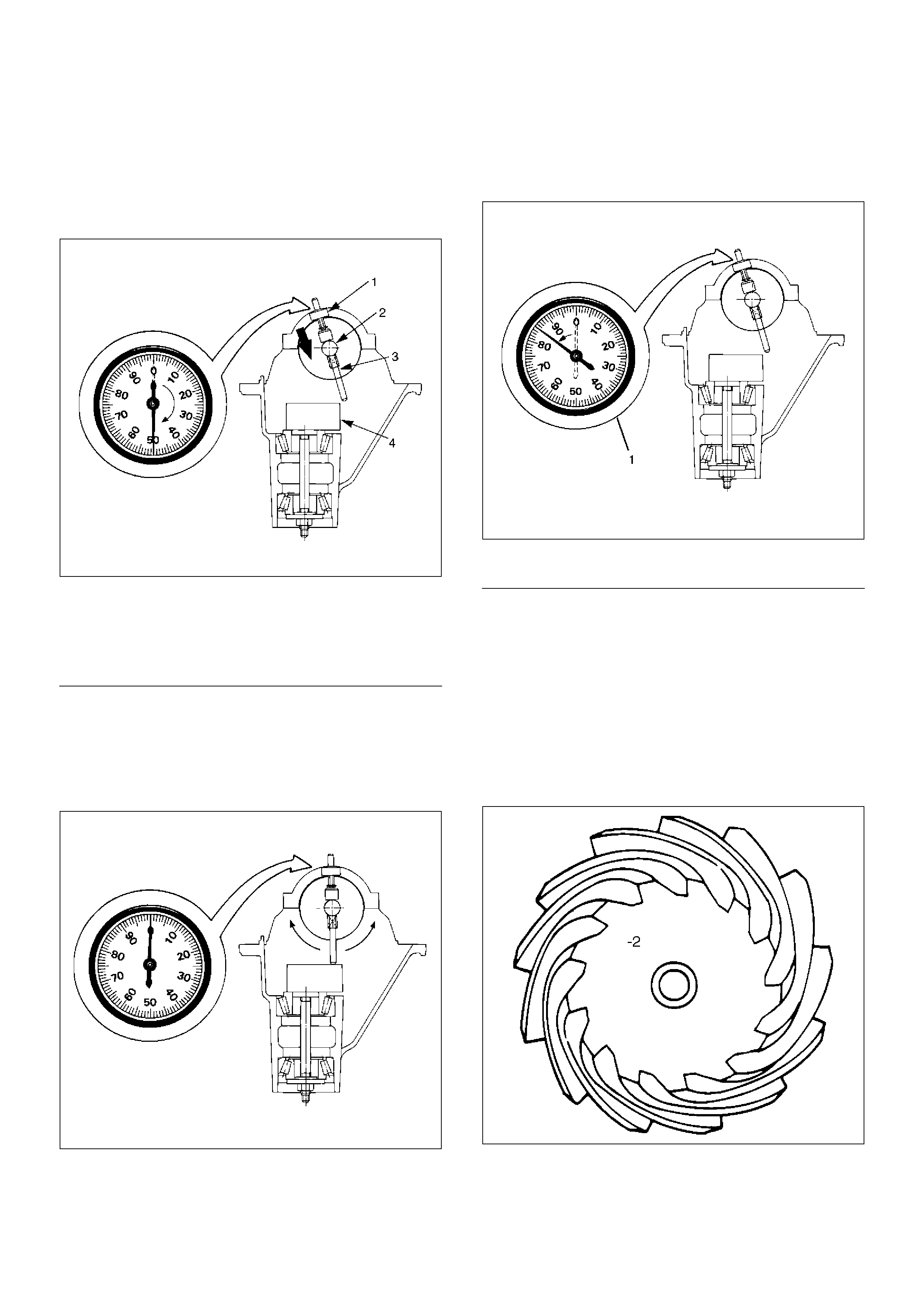
4. Set the dial indicator 5–8840–0126–0 to“0”.
Place it on the mounting post of the gauging
arbor with the contact button touching the
indicator pad. Force the dial indicator downward
until the needle has made a half turn clockwise.
Tighten down the dial indicator in this position.
425RS020
EndOFCallout
5. Position the plunger on the gauge plate. Move
the gauging arbor slowly back and forth and
locate the position at which the dial indicator
shows the greatest defection. At this point, once
again set the dial indicator to“0”. Repeat the
procedure to verify the “0” setting.
425RS021
6. After the ZERO setting is obtained, rotate the
gauging arbor until the dial indicator rod does
not touch the gauging plate. Record the number
the dial indicator needle points to.
425RS022
EndOFCallout
7. Record the pinion depth code on the head of
the drive pinion. The number indicates a
necessary change in the pinion mounting
distance. A plus number indicates the need for
a greater mounting distance (which can be
achieved by decreasing the shim thickness). A
minus number indicates the need for a smaller
mounting distance (which can be achieved by
increasing the shim thickness). If examination
reveals pinion depth code“0”, the pinion
is“nominal”.
425RS023
Legend
(1) Dial Indicator
(2) Ganging Arbor
(3) Plunger
(4) Gauge Plate
Legend
(1) Example=Dial indicator reading od 0.085
8. Select the shim thickness using the chart;
Pinion marking
Dial indicator reading(inches)
+10+9+8+7+6+5+4+3+2+1 0 –1–2–3–4–5–6–7 –8 –9 –10
0.080
2.12
(0.08
35)
2.12
(0.08
35)
0.081
2.12
(0.0
835)
2.12
(0.0
835)
2.14
(0.08
43)
2.14
(0.08
43)
2.16
(0.08
50)
0.082
2.12
(0.0
835)
2.12
(0.0
835)
2.14
(0.0
843)
2.14
(0.0
843)
2.16
(0.0
850)
2.16
(0.08
50)
2.18
(0.08
58)
2.18
(0.08
58)
0.083
2.12
(0.0
835)
2.12
(0.0
835)
2.14
(0.0
843)
2.14
(0.0
843)
2.16
(0.0
850)
2.16
(0.0
850)
2.18
(0.0
858)
2.18
(0.08
58)
2.20
(0.08
66)
2.20
(0.08
66)
0.084
2.12
(0.0
835)
2.12
(0.0
835)
2.14
(0.0
843)
2.14
(0.0
843)
2.16
(0.0
850)
2.16
(0.0
850)
2.18
(0.0
858)
2.18
(0.0
858)
2.20
(0.0
866)
2.20
(0.08
66)
2.22
(0.08
74)
2.22
(0.08
74)
0.085
2.12
(0.0
835)
2.12
(0.0
835)
2.14
(0.0
843)
2.14
(0.0
843)
2.16
(0.0
850)
2.16
(0.0
850)
2.18
(0.0
858)
2.18
(0.0
858)
2.20
(0.0
866)
2.20
(0.0
866)
2.22
(0.0
874)
2.22
(0.0
874)
2.24
(0.08
22)
2.24
(0.08
22)
2.26
(0.08
90)
0.086
2.12
(0.0
835)
2.12
(0.0
835)
2.14
(0.0
843)
2.14
(0.0
843)
2.16
(0.0
850)
2.16
(0.0
850)
2.18
(0.0
858)
2.18
(0.0
858)
2.20
(0.0
866)
2.20
(0.0
866)
2.22
(0.0
874)
2.22
(0.0
874)
2.24
(0.0
882)
2.24
(0.0
882)
2.26
(0.0
890)
2.26
(0.08
90)
2.28
(0.08
98)
2.28
(0.08
98)
0.087
2.12
(0.0
835)
2.12
(0.0
835)
2.14
(0.0
843)
2.14
(0.0
843)
2.16
(0.0
850)
2.16
(0.0
850)
2.18
(0.0
858)
2.18
(0.0
858)
2.20
(0.0
866)
2.20
(0.0
866)
2.22
(0.0
874)
2.22
(0.0
874)
2.24
(0.0
882)
2.24
(0.0
882)
2.26
(0.0
890)
2.26
(0.0
890)
2.28
(0.0
898)
2.28
(0.08
98)
2.30
(0.09
05)
2.30
(0.09
05)
0.088
2.14
(0.0
843)
2.14
(0.0
843)
2.16
(0.0
850)
2.16
(0.0
850)
2.18
(0.0
858)
2.18
(0.0
858)
2.20
(0.0
866)
2.20
(0.0
866)
2.22
(0.0
874)
2.22
(0.0
874)
2.24
(0.0
882)
2.24
(0.0
882)
2.26
(0.0
890)
2.26
(0.0
890)
2.28
(0.0
898)
2.28
(0.0
898)
2.30
(0.0
905)
2.30
(0.0
905)
2.32
(0.09
14)
2.32
(0.09
14)
2.34
(0.09
21)
0.089
2.16
(0.0
850)
2.18
(0.0
858)
2.18
(0.0
858)
2.20
(0.0
866)
2.20
(0.0
866)
2.22
(0.0
874)
2.22
(0.0
874)
2.24
(0.0
882)
2.24
(0.0
882)
2.26
(0.0
890)
2.26
(0.0
890)
2.28
(0.0
898)
2.28
(0.0
898)
2.30
(0.0
905)
2.30
(0.0
905)
2.32
(0.0
914)
2.32
(0.0
914)
2.34
(0.0
921)
2.34
(0.09
21)
2.36
(0.09
29)
2.36
(0.09
29)
0.090
2.18
(0.0
858)
2.20
(0.0
866)
2.20
(0.0
866)
2.22
(0.0
874)
2.22
(0.0
874)
2.24
(0.0
882)
2.24
(0.0
882)
2.26
(0.0
890)
2.26
(0.0
890)
2.28
(0.0
898)
2.28
(0.0
898)
2.30
(0.0
905)
2.30
(0.0
905)
2.32
(0.0
914)
2.32
(0.0
914)
2.34
(0.0
921)
2.34
(0.0
921)
2.36
(0.0
929)
2.36
(0.09
29)
2.38
(0.09
37)
2.38
(0.09
37)
0.091
2.20
(0.0
866)
2.22
(0.0
874)
2.22
(0.0
874)
2.24
(0.0
882)
2.24
(0.0
882)
2.26
(0.0
890)
2.26
(0.0
890)
2.28
(0.0
898)
2.28
(0.0
898)
2.30
(0.0
905)
2.30
(0.0
905)
2.32
(0.0
914)
2.32
(0.0
914)
2.34
(0.0
921)
2.34
(0.0
921)
2.36
(0.0
929)
2.36
(0.0
929)
2.38
(0.0
937)
2.38
(0.09
37)
2.40
(0.09
45)
2.40
(0.09
45)
0.092
2.24
(0.0
882)
2.24
(0.0
882)
2.26
(0.0
890)
2.26
(0.0
890)
2.28
(0.0
898)
2.28
(0.0
898)
2.30
(0.0
905)
2.30
(0.0
905)
2.32
(0.0
914)
2.32
(0.0
914)
2.34
(0.0
921)
2.34
(0.0
921)
2.36
(0.0
929)
2.36
(0.0
929)
2.38
(0.0
937)
2.38
(0.0
937)
2.40
(0.0
945)
2.40
(0.0
945)
2.42
(0.09
53)
2.42
(0.09
53)
2.44
(0.09
61)
0.093
2.26
(0.0
890)
2.28
(0.0
898)
2.28
(0.0
898)
2.30
(0.0
905)
2.30
(0.0
905)
2.32
(0.0
914)
2.32
(0.0
914)
2.34
(0.0
921)
2.34
(0.0
921)
2.36
(0.0
929)
2.36
(0.0
929)
2.38
(0.0
937)
2.38
(0.0
937)
2.40
(0.0
945)
2.40
(0.0
945)
2.42
(0.0
953)
2.42
(0.0
953)
2.44
(0.0
961)
2.44
(0.09
61)
2.46
(0.09
69)
2.46
(0.09
69)
0.094
2.28
(0.0
898)
2.30
(0.0
905)
2.30
(0.0
905)
2.32
(0.0
914)
2.32
(0.0
914)
2.34
(0.0
921)
2.34
(0.0
921)
2.36
(0.0
929)
2.36
(0.0
929)
2.38
(0.0
937)
2.38
(0.0
937)
2.40
(0.0
945)
2.40
(0.0
945)
2.42
(0.0
953)
2.42
(0.0
953)
2.44
(0.0
961)
2.44
(0.0
961)
2.46
(0.0
969)
2.46
(0.09
69)
2.48
(0.09
77)
2.48
(0.09
77)
0.095
2.30
(0.0
905)
2.32
(0.0
914)
2.32
(0.0
914)
2.34
(0.0
921)
2.34
(0.0
921)
2.36
(0.0
929)
2.36
(0.0
929)
2.38
(0.0
937)
2.38
(0.0
937)
2.40
(0.0
945)
2.40
(0.0
945)
2.42
(0.0
953)
2.42
(0.0
953)
2.44
(0.0
961)
2.44
(0.0
961)
2.46
(0.0
969)
2.46
(0.0
969)
2.48
(0.0
977)
2.48
(0.09
77)
2.50
(0.09
87)
2.50
(0.09
87)
0.096
2.34
(0.0
921)
2.34
(0.0
921)
2.36
(0.0
929)
2.36
(0.0
929)
2.38
(0.0
937)
2.38
(0.0
937)
2.40
(0.0
945)
2.40
(0.0
945)
2.42
(0.0
953)
2.42
(0.0
953)
2.44
(0.0
961)
2.44
(0.0
961)
2.46
(0.0
969)
2.46
(0.0
969)
2.48
(0.0
977)
2.48
(0.0
977)
2.50
(0.0
987)
2.50
(0.0
987)
2.52
(0.09
92)
2.52
(0.09
92)
2.54
(0.10
00)
0.097
2.36
(0.0
929)
2.38
(0.0
937)
2.38
(0.0
937)
2.40
(0.0
945)
2.40
(0.0
945)
2.42
(0.0
953)
2.42
(0.0
953)
2.44
(0.0
961)
2.44
(0.0
961)
2.46
(0.0
969)
2.46
(0.0
969)
2.48
(0.0
977)
2.48
(0.0
977)
2.50
(0.0
984)
2.50
(0.0
984)
2.52
(0.0
992)
2.52
(0.0
922)
2.54
(0.1
000)
2.54
(0.10
00)
2.56
(0.10
08)
2.56
(0.10
08)
0.098
2.38
(0.0
937)
2.40
(0.0
945)
2.40
(0.0
945)
2.42
(0.0
953)
2.42
(0.0
953)
2.44
(0.0
961)
2.44
(0.0
961)
2.46
(0.0
969)
2.46
(0.0
969)
2.48
(0.0
977)
2.48
(0.0
977)
2.50
(0.0
984)
2.50
(0.0
984)
2.52
(0.0
992)
2.52
(0.0
922)
2.54
(0.1
000)
2.54
(0.1
000)
2.56
(0.1
008)
2.56
(0.10
08)
2.58
(0.10
16)
2.58
(0.10
16)
0.099
2.42
(0.0
953)
2.42
(0.0
953)
2.44
(0.0
961)
2.44
(0.0
961)
2.46
(0.0
969)
2.46
(0.0
969)
2.48
(0.0
977)
2.48
(0.0
977)
2.50
(0.0
984)
2.50
(0.0
984)
2.52
(0.0
992)
2.52
(0.0
922)
2.54
(0.1
000)
2.54
(0.1
000)
2.56
(0.1
008)
2.56
(0.1
008)
2.58
(0.1
016)
2.58
(0.1
016)
4. Place the shim (1) on the drive pinion, then install
the inner bearing (2) onto the pinion by using
installer 5–8840–2574–0 and a press .
NOTE: Do not apply pressure to the roller cage. Apply
pressure only to the inner race.
425RW061
5. Install collapsible spacer. Discard the used
collapsible spacer and install a new one.
6. Install drive pinion shaft assembly.
7. Install outer bearing and oil seal slinger.
8. Use oil seal installer 5–8840–2165–0 to install a
new oil seal that has grease on seal lip.
415RW029
9. Install flange assembly.
0.000
2.44
(0.0
961)
2.46
(0.0
969)
2.46
(0.0
969)
2.48
(0.0
977)
2.48
(0.0
977)
2.50
(0.0
984)
2.50
(0.0
984)
2.52
(0.0
992)
2.52
(0.0
922)
2.54
(0.1
000)
2.54
(0.1
000)
2.56
(0.1
008)
2.56
(0.1
008)
2.58
(0.1
016)
2.58
(0.1
016)
0.001
2.46
(0.0
969)
2.48
(0.0
977)
2.48
(0.0
977)
2.50
(0.0
984)
2.50
(0.0
984)
2.52
(0.0
992)
2.52
(0.0
922)
2.54
(0.1
000)
2.54
(0.1
000)
2.56
(0.1
008)
2.56
(0.1
008)
2.58
(0.1
016)
2.58
(0.1
016)
0.002
2.48
(0.0
977)
2.50
(0.0
984)
2.50
(0.0
984)
2.52
(0.0
992)
2.52
(0.0
922)
2.54
(0.1
000)
2.54
(0.1
000)
2.56
(0.1
008)
2.56
(0.1
008)
2.58
(0.1
016)
2.58
(0.1
016)
0.003
2.52
(0.0
992)
2.52
(0.0
922)
2.54
(0.1
000)
2.54
(0.1
000)
2.56
(0.1
008)
2.56
(0.1
008)
2.58
(0.1
016)
2.58
(0.1
016)
0.004
2.54
(0.1
000)
2.56
(0.1
008)
2.56
(0.1
008)
2.58
(0.1
016)
2.58
(0.1
016)
0.005
2.56
(0.1
008)
2.58
(0.1
016)
2.58
(0.1
016)
0.006
2.58
(0.1
016)
Pinion marking
Dial indicator reading(inches)
+10+9+8+7+6+5+4+3+2+1 0 –1–2–3–4–5–6–7 –8 –9 –10
10. Install flange nut and washer.
1. Apply lubricant to the pinion threads.
2. Using the pinion flange holder 5–8840–0133–0,
tighten the nut only enough to remove the shaft
end play.
NOTE: Discard used flange nut and install new one.
415RW006
3. Adjust pinion bearing preload.
a Measure the bearing preload by using a
torque meter and note the scale reading
required to rotate the flange.
b Continue tightening flange nut until the
specified starting torque is obtained.
Starting torque: 1.1–1.6 N·m (11–16kg·cm/10–14
lbin)
NOTE:
Do not overtighten or loosen and then retighten the nut.
Pinion nut torque should be in the range of 298–380
N·m (30.4–38.8kg·m/220–281 Ib ft).
425RW018
4. Using punch 5–8840–2293–0, stake the flange
nut at two points.
NOTE: When staking, be sure to turn the nut to ensure
that there is no change in bearing preload. Make sure
of preload again as instructed in 3).
425RW062
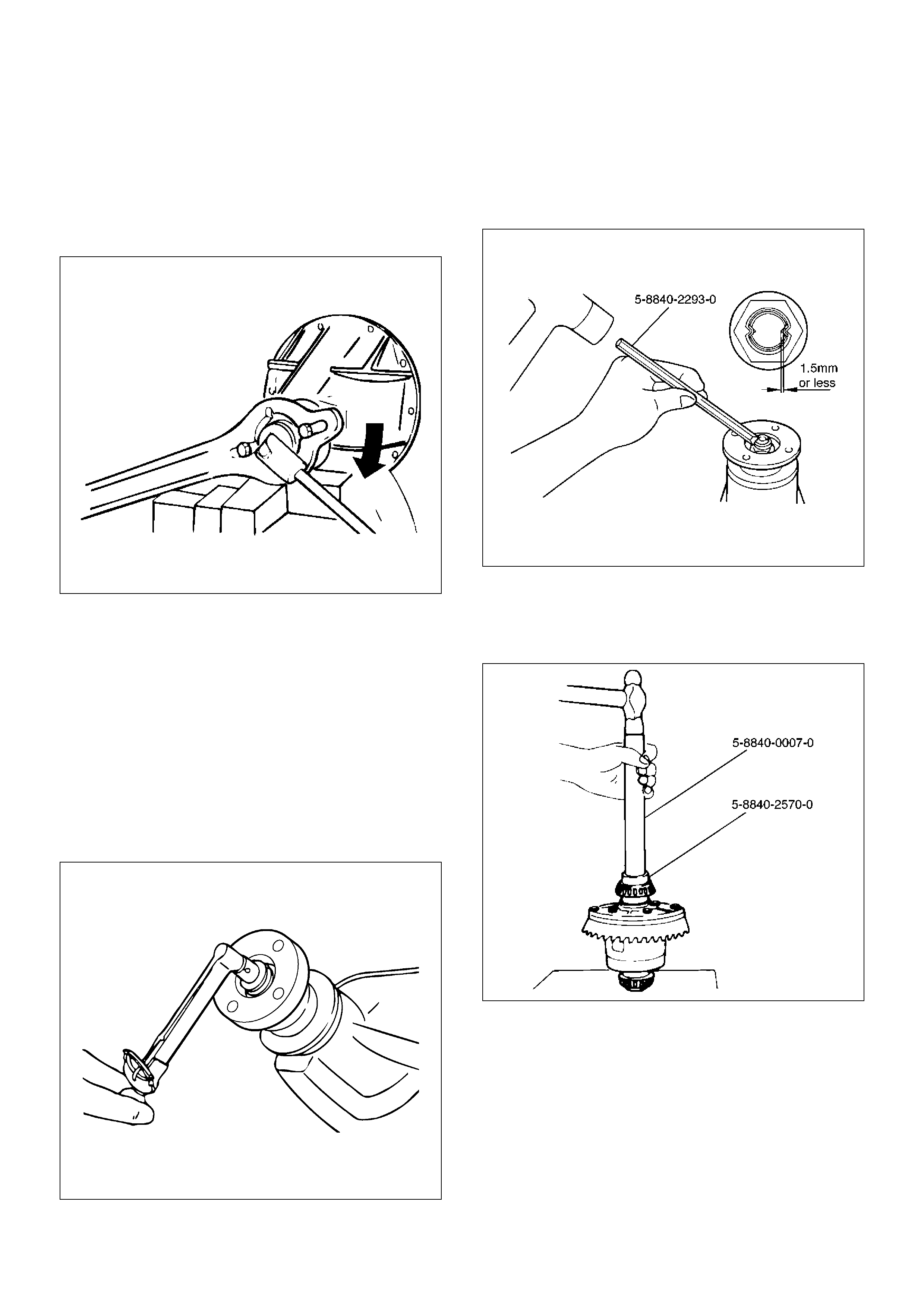
11. Adjust ring gear backlash.
1. Attach the side bearing to the differential
assembly without shims by using installer 5–
8840–2050–0 and grip 5–8840–0007–0.
425RW063
2. Insert the differential cage assembly with
bearing outer races into the side bearing bores
of the carrier.
425RS030
3. Using two sets of feeler gauges, insert a feeler
stock of sufficient thickness between each
bearing outer race and the carrier to remove all
end play. Make certain the feeler stock is
pushed to the bottom of the bearing bores.
Mount the dial indicator 5–8840–0126–0 on the
carrier so that the indicator stem is at right
angles to a tooth on the ring gear.
425RW049
4. Adjust feeler gauge thickness from side to side
until ring gear backlash is in the specified range.
Backlash:0.13– 0.2mm (0.005– 0.008in)
425RS032
With zero end play and correct backlash
established, remove the feeler gauge packs,
determine the thickness of the shims required
and add 0.05 mm (0.002 in) to each shim pack
to provide side bearing preload. Always use
new shims.
5. Remove side bearing by using remover 5–
8840–2587–0 and adapter 5–8840–2576–0.
415RW041
12. Install the side bearings together with the selected
shims by using installer 5–8840–2050–0 (2) and
grip 5–8840–0007–0 (1).
425RW032
13. Install side bearing outer race.
14. Install differential cage assembly.
15. Align the setting marks (1) applied at disassembly
then install the bearing cap.
425RS035
16. Tighten the bolt to the specified torque.
Torque:108N·m (11.0kg·m/80lbft)
425RS036
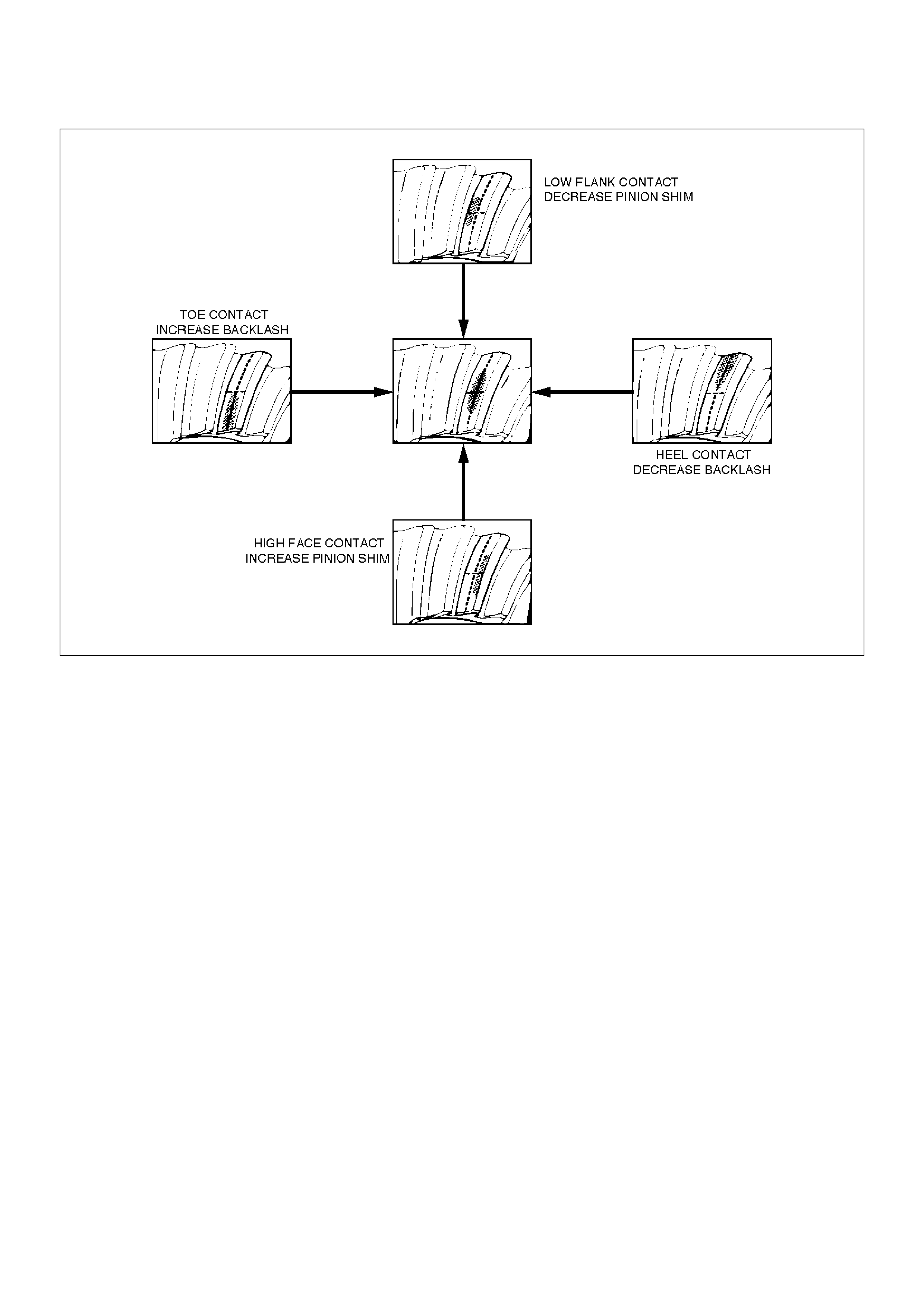
Gear Tooth Contact Pattern Check and Adjustment
1. Apply a thin coat of Prussian blue or equivalent to
the faces of the 7–8 teeth of the ring gear. Check
the impression of contact on the ring gear teeth and
make necessary adjustment as described in
illustration if the contact is abnormal.
425RS038
EndOFCallout
Legend
(1) Heel
(2) Toe
(3) Concave Side(Coast)
(4) Convex Side(Drive)
425RS039
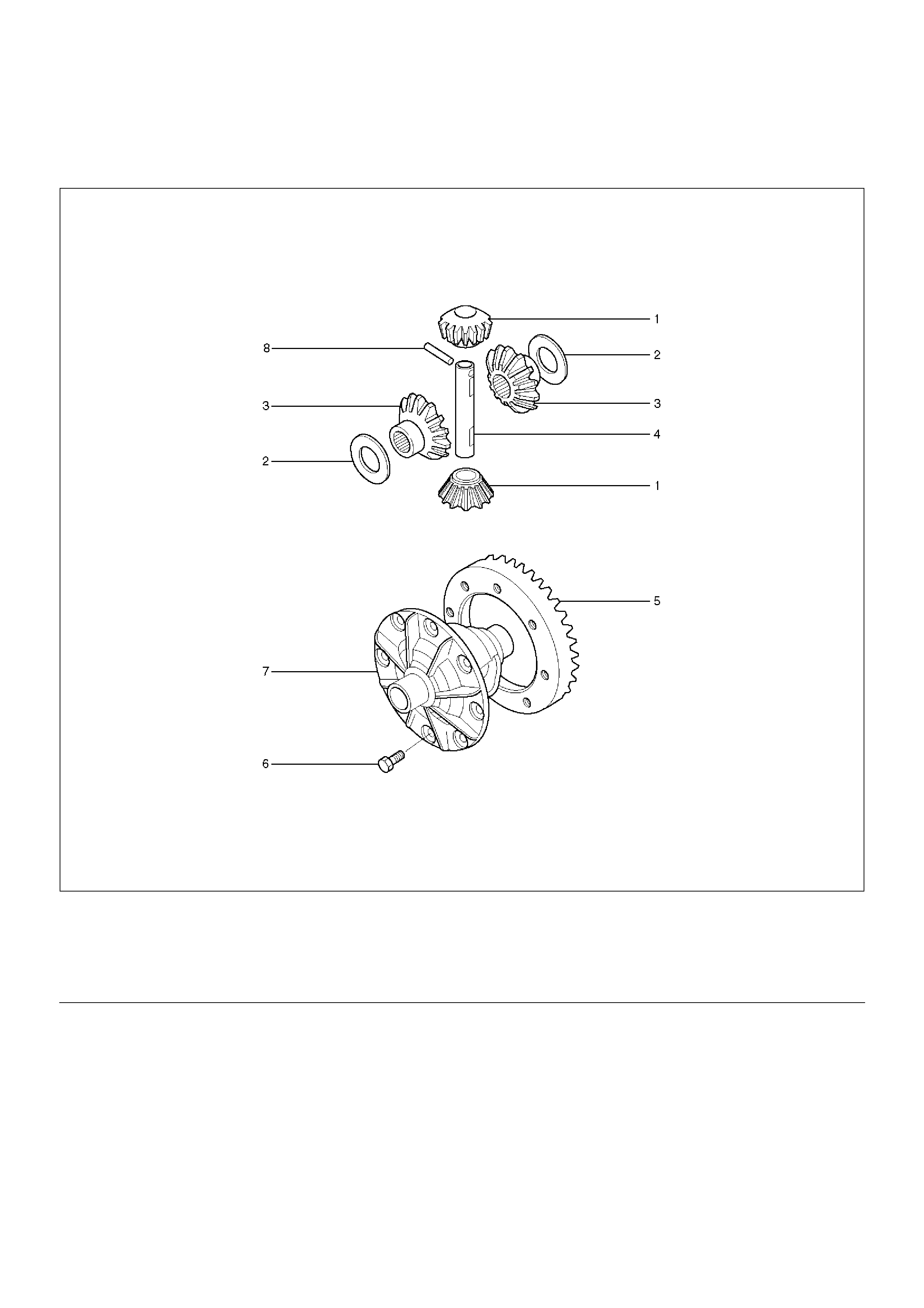
Differential Cage Assembly
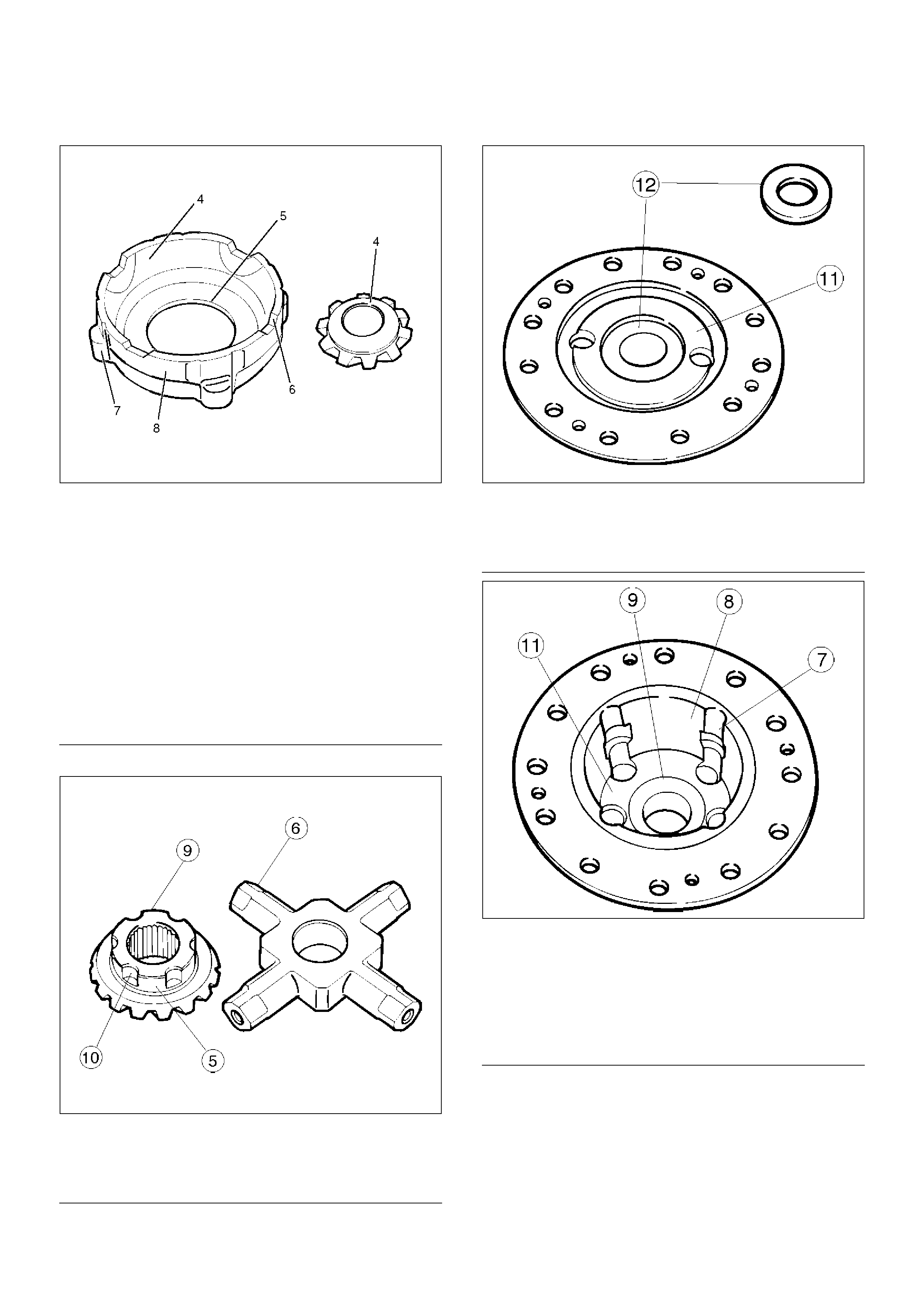
Disassembled View
415RY00001
EndOFCallout
Legend
(1) Pinion Mate Gear
(2) Thrust Washer(for Side Gear)
(3) Side Gear
(4) Differential Shaft
(5) Ring Gear
(6) Bolt
(7) Differention Cage
(8) Lock Pin
Disassembly
1. Remove bolt.
2. Remove ring gear.
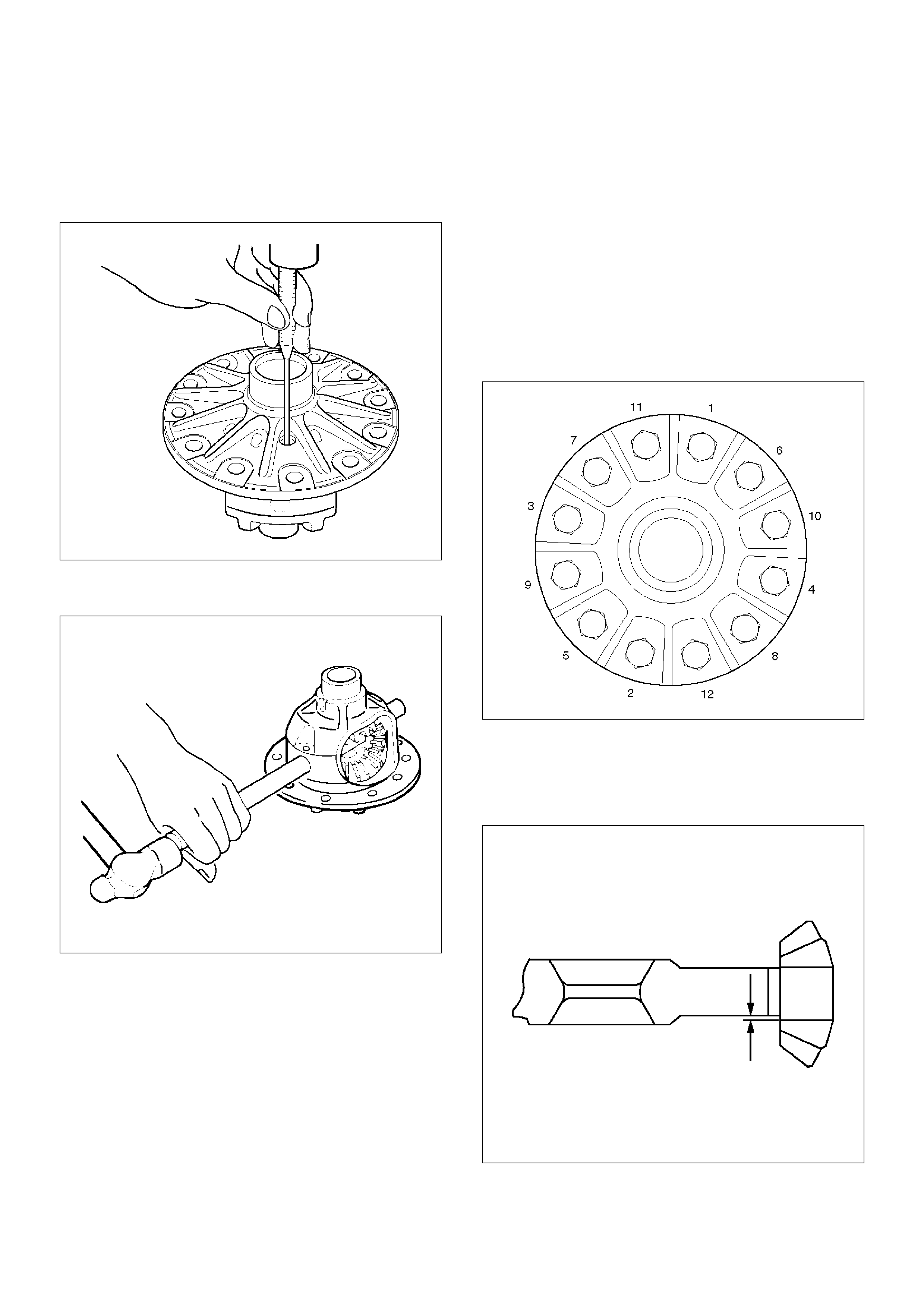
3. Remove lock pin using a small drift.
425RY00002
4. Remove the differential shaft by using a hard metal
rod and a hammer.
425RS043
5. Remove pinion mate gear and thrust washer.
6. Remove side gear and thrust washer.
Inspection and Repair
Make necessary correction or parts replacement if
wear, damage, corrosion or any other abnormal
conditions are found through inspection.
Check the following parts:
• Ring gear, pinion gear
• Bearing
• Side gear, pinion mate gear, differential shaft
• Differential cage, carrier
• Thrust washer
• Oil seal
Ring gear replacement:
1. The ring gear should always be replaced with the
drive pinion as a set.
2. Clean the ring gear threaded holes to remove the
locking argent.
3. Discard used bolts and install new ones.
4. When installing the ring gear, apply LOCTITE 271
or equivalent to all the threaded area and ha of the
unthreaded area of the bolt.
Torque: 127N·m (13.0kg·m/94lbft)
425RW033
Clearance between the differential pinion and the
pinion shaft measurement.
Standard: 0.07 – 0.13 mm (0.003 – 0.005 in)
Limit: 0.2 mm (0.008 in)
425RY00007
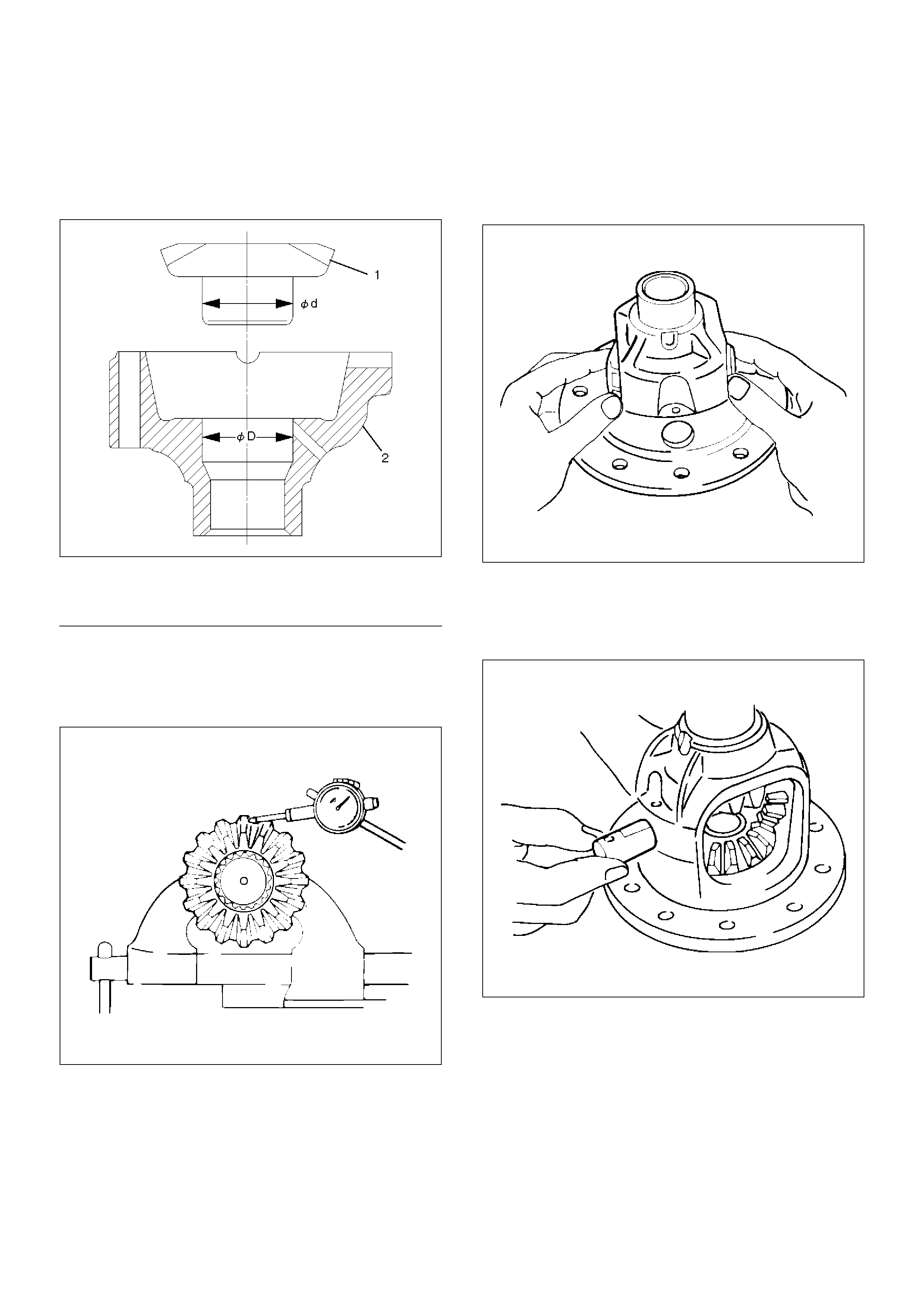
Clearance between the side gear and the differential
box.
Standard: 0.032 – 0.105 mm (0.001 – 0.004 in)
Limit: 0.105 mm (0.004 in)
425RY00005
EndOFCallout
Play in splines between the side gear and the axle
shaft.
Standard: 0.07 – 0.38 mm (0.003 – 0.014 in)
Limit: 0.5 mm (0.02 in)
425RY00006
Reassembly
Differential cage
Thrust washer
Side gear
Pinion gear
1. Install the pinion gear by engaging it with the side
gears while turning both pinion gears
simultaneously in the same direction.
2. Install the pinion mate gear with thrust washer by
engaging it with the side gears while turning both
pinion mate gears simultaneously in the same
direction.
425RS048
3. Install differential shaft.
1. Be sure to install the differential shaft so that it
is in alignment with the lock pin hole in the
differential cage.
425RS049
Legend
(1) Side gear
(2) Differential box
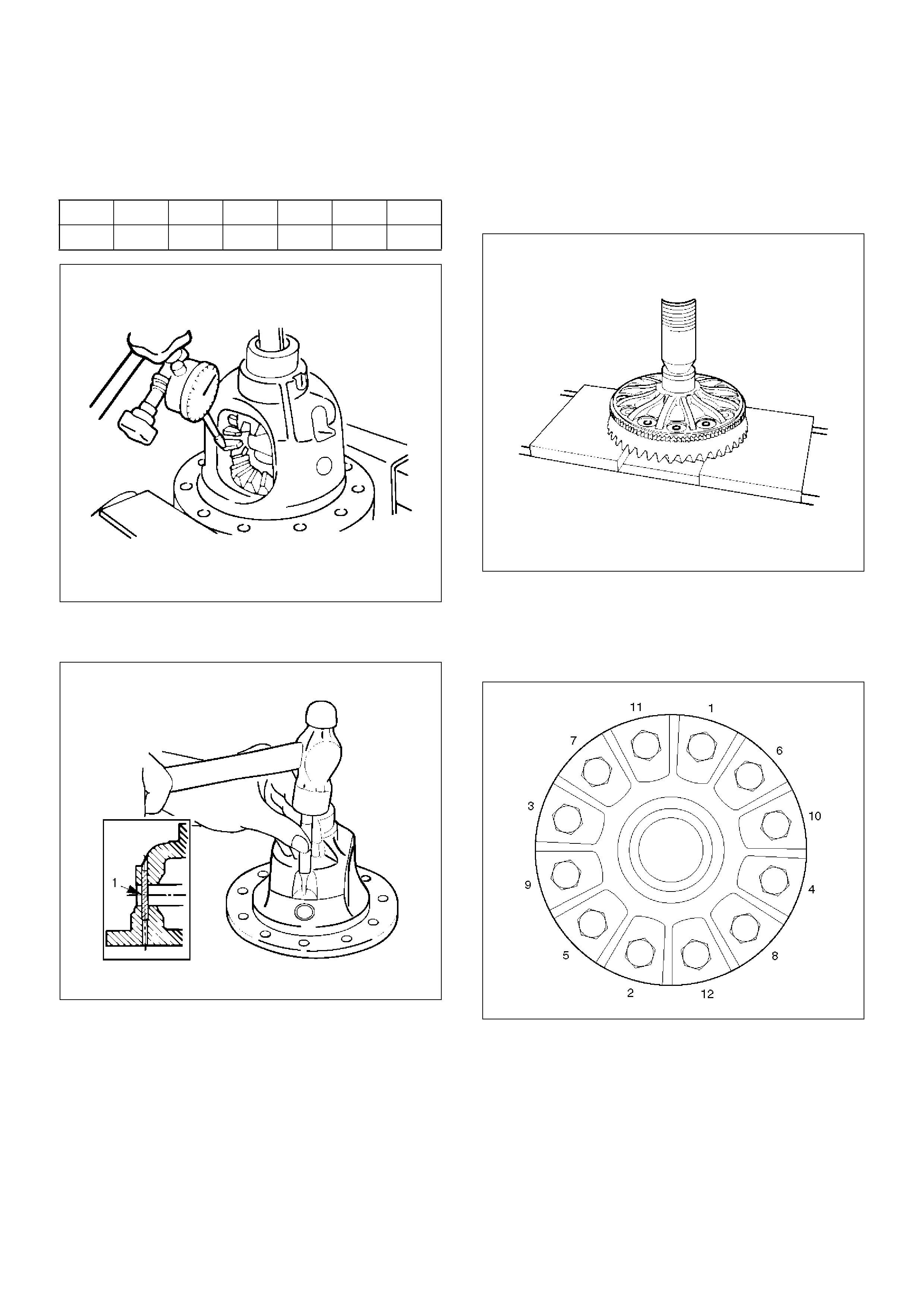
2. Adjust the backlash between the side gear and
the pinion gear.
Backlash: 0.15 – 0.20 mm (0.006 – 0.008 in)
Thickness of thrust washers ava ilable
425RY00008
4. Install lock pin.
• Install the lock pin using small drift.
425RY00009
5. Install exciter ring (If equipped with rear wheel
antilock).
• Press the exciter ring on the differential cage
using the ring gear as a pilot.
NOTE: Discard used exciter ring and install new one.
425RS052
6. Tighten the bolts in diagonal sequence as
illustrated.
Torque: 127N·m (13.0kg·m/94lbft)
NOTE: Discard used bolts and install new ones.
425RW033
mm 0.80 0.90 1.00 1.10 1.20 1.30
in 0.031 0.035 0.039 0.043 0.047 0.051
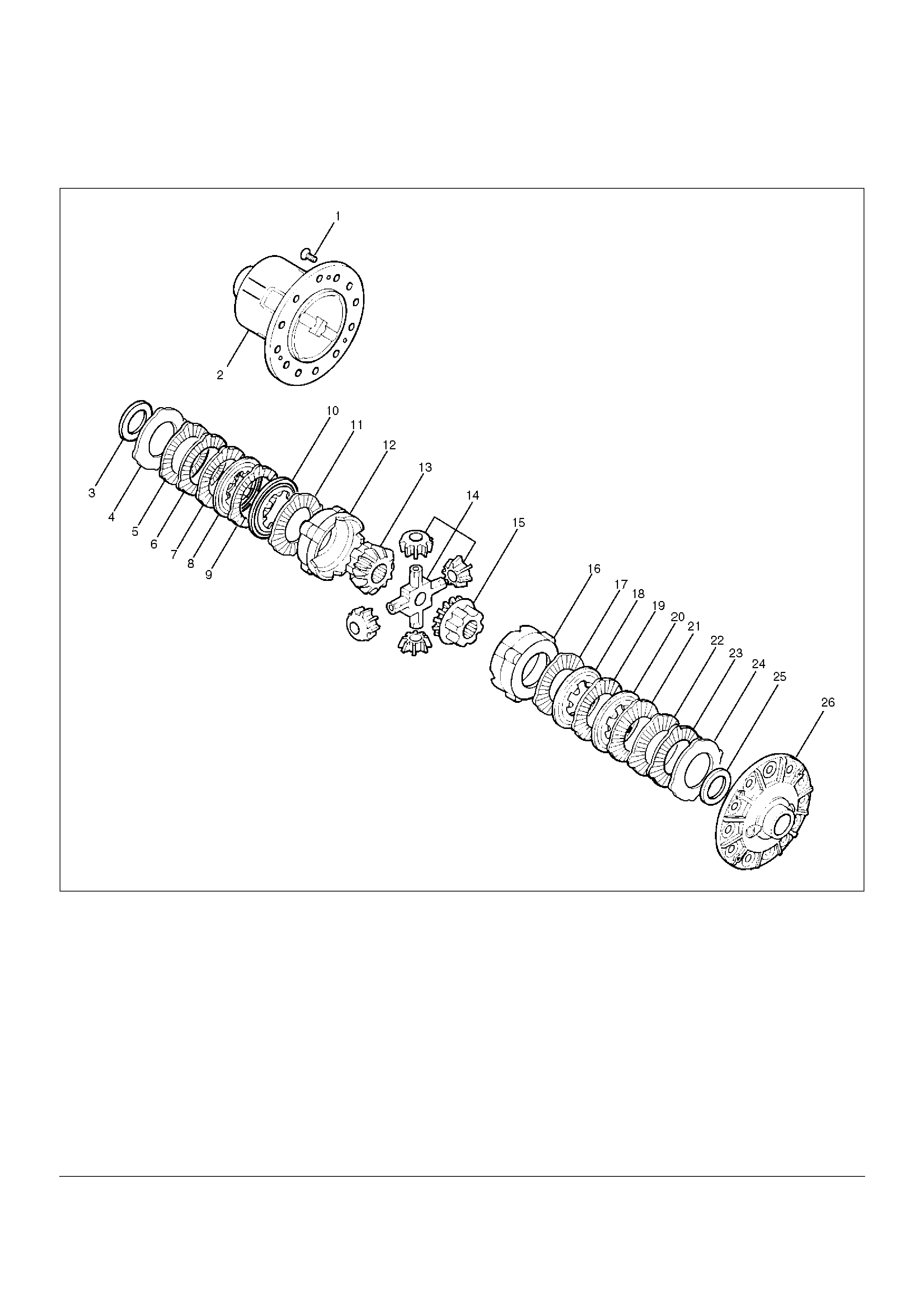
Limited Slip Differential
Disassembled View
425RY001
EndOFCallout
Legend
(1) Screw
(2) Differential cage A
(3) Thrust washer
(4) Spring disc
(5) Friction Plate
(6) Friction plate
(7) Friction Plate
(8) Friction disc
(9) Friction Plate
(10) Friction disc
(11) Friction Plate
(12) Pressure ring
(13) Side gear
(14) Pinion and Pinion shaft
(15) Side gear
(16) Pressure ring
(17) Friction Plate
(18) Friction disc
(19) Friction Plate
(20) Friction disc
(21) Friction Plate
(22) Friction Plate
(23) Friction Plate
(24) Spring disc
(25) Thrust washer
(26) Differential cage B
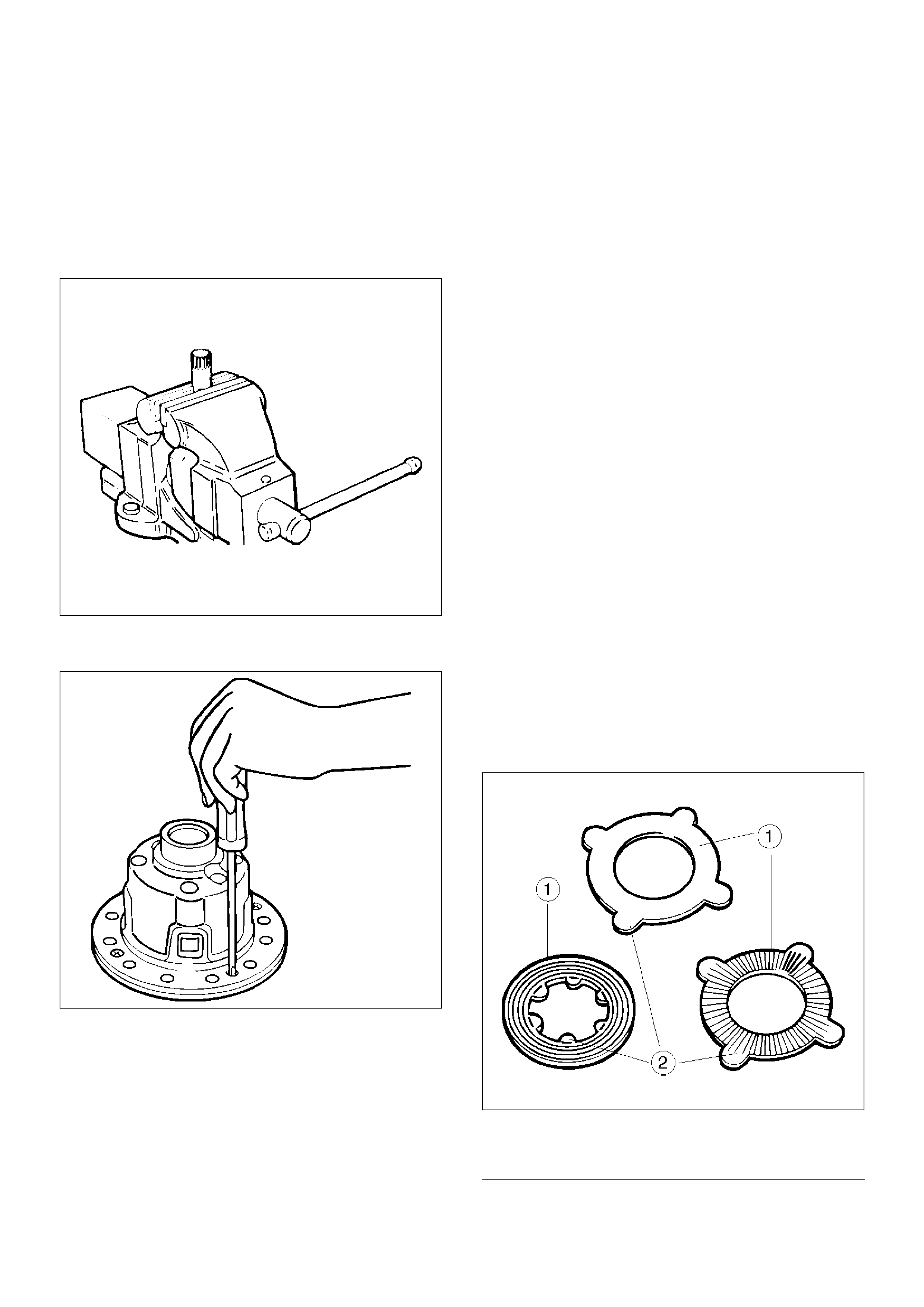
Disassembly
Differential Cages A and B
1. To ensure installation of the parts in original position
apply a setting mark before removing the differential
cages A and B.
2. Using special tool, 5–8840–2682–0, grip it with a
vice, and set the differential.
425RS054
3. Gradually and evenly loosen the 3 fixing screws of
the differential cages A and B.
425RS055
4. Remove Differential cage A.
5. Remove Thrust washer.
6. Remove Spring disc.
NOTE: When removing the spring disc, friction disc,
and friction plate, place them in order for clear
distinction of left and right use.
7. Remove Spring disc.
8. Remove Friction plate.
9. Remove Friction plate.
10. Remove Friction disc.
11. Remove Friction plate.
12. Remove Friction disc.
13. Remove Friction plate.
14. Remove Pressure ring.
15. Remove Side gear.
16. Remove Pinion and pinion shaft.
17. Remove Side gear.
18. Remove Pressure ring.
19. Remove Friction plate.
20. Remove Friction disc.
21. Remove Friction plate.
22. Remove Friction disc.
23. Remove Friction plate.
24. Remove Friction plate.
25. Remove Friction plate.
26. Remove Friction disc.
27. Remove Thrust washer.
28. Remove Differential cage B.
Inspection and Repair
Make necessary correction or parts replacement if wear,
damage, corrosion or any other abnormal condition is
found through inspection.
Visual check
Check the following parts for wear, damage, noise or
any other abnormal conditions.
• Friction disc, friction plate and spring disc
425RS056
E n dO FC al lo ut
Legend
(1) Sliding surfaces
(2) Projections
• Pressure ring
425RY003
E n dO FC al lo ut
• Thrust washer
425RS058
E n dO FC al lo ut
•Case
425RS059
E n dO FC al lo ut
425RS060
EndOFCallout
Legend
(3) Sliding surface with the friction disc. When
nicks or scratches are found, polish with an oil
stone and repair on a level block using a
compound.
(4) Sliding spherical surface with the pinion gear.
(5) Sliding surface with the side gear.
(6) V–shaped groove of the pressure ring and V –
shaped section of the pinion shaft.
(7) Fitting section with the case.
(8) Face contacting the inner surface of the
differential case. Repair burrs and nicks using
an oil stone.
Legend
(9) Sliding surface with the side gear or case.
(10) Peripheral groove of the side gear.
Repair light nicks and burrs using an oil stone.
Legend
(11) Contact surface with the spring disc.
(12) Inner groove of the differential cage B.
Repair light nicks and burrs using an oil stone.
Legend
(7) Fitting section with the case.
(8) Face contacting the inner surface of the
differential case.
Repair burrs and nicks using an oil stone.
(9) Sliding surface with the side gear or case.
(11) Contact surface with spring disc.
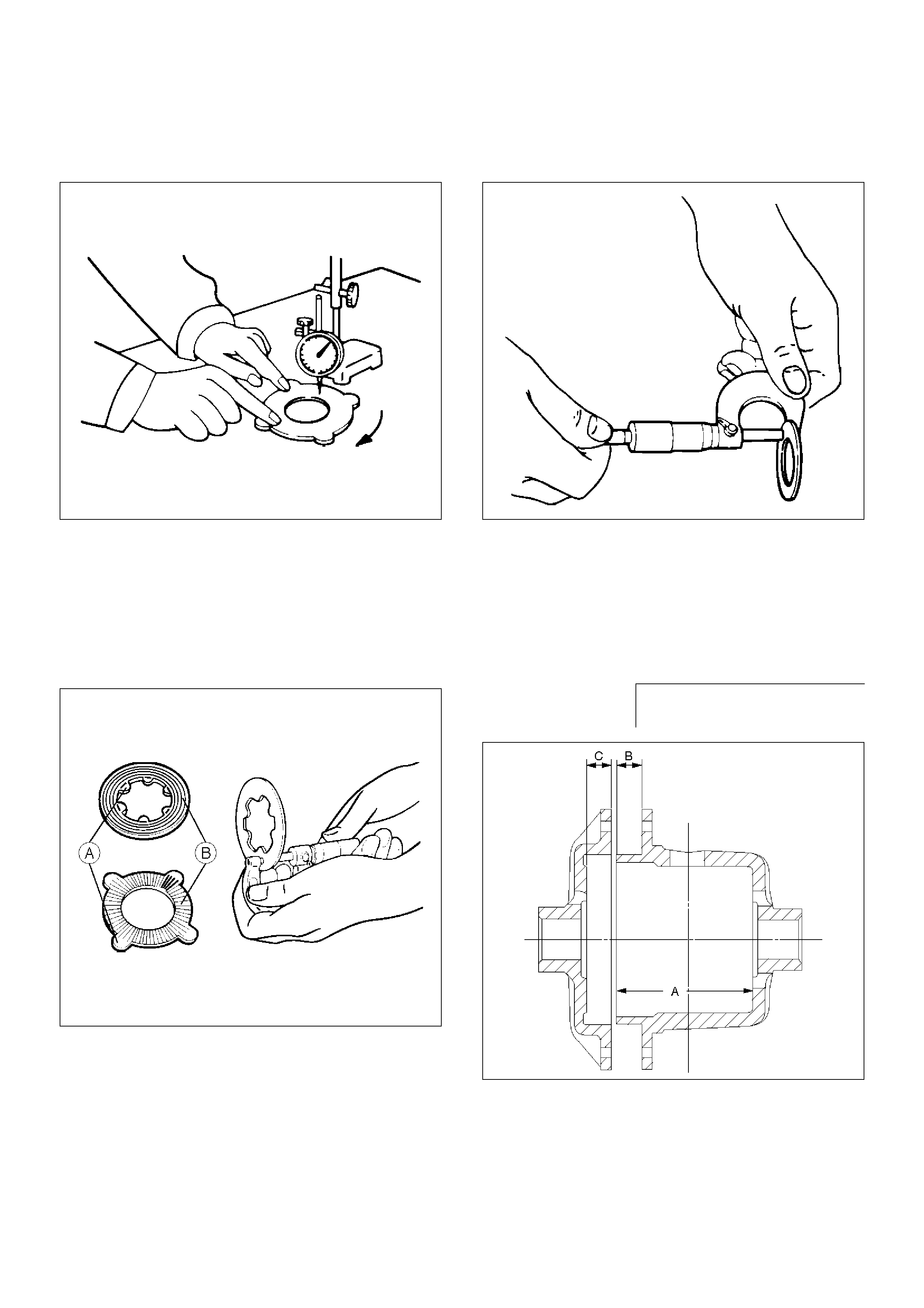
Measure the Deformation of the friction disc & plate.
Limit: 0.1mm(0.004in)
425RS061
Measure the wear of the friction plate & disc
Limit(A-B): 0.1mm(0.004in)
Remarks:
A=Inner or outer projections
B=Sliding surface subjected to abrasion
425RS062
Measure the wear of the thrust washer
Limit:1.3mm(0.05in)
425RS063
Reassembly
Adjust the clearance between the friction disc and plate.
1. Measuring the depth of the differential cage.
425RS064
Standard(A–B):
89.13mm(3.51in)
(C):
9.13mm(0.36in)
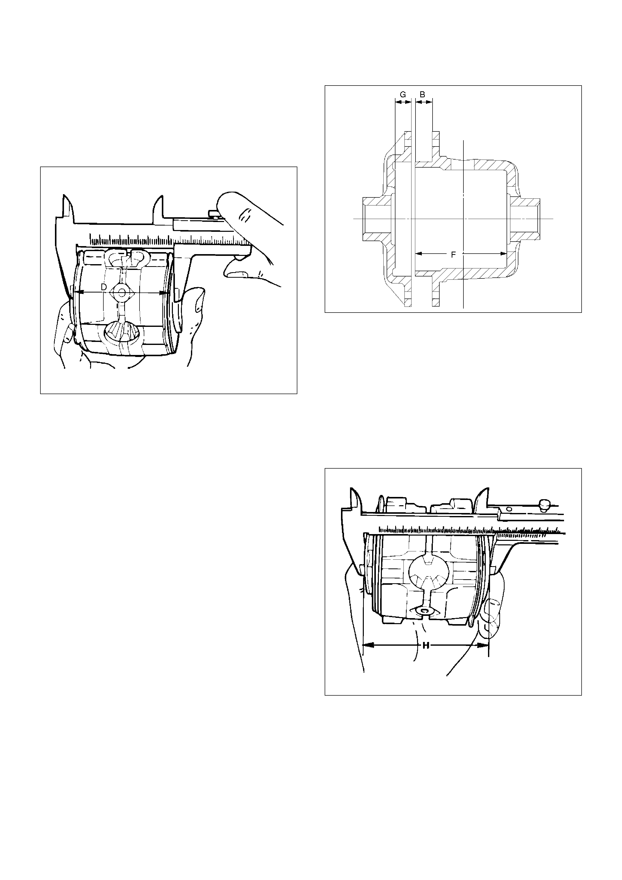
2. Measuring the overall length of the pressurering,
friction disc and friction plate.
• Mount the pinion shaft in the pressurering and
then install the friction disc & plate.
• Measure the length between the plates over the
V–groove.(D)
425RS065
3. After measuring dimensions A,B,C and D, make
adjustment in the following manner:
• Measure the thickness(E)of the spring disc.
1.75mm(0.069in)´2discs
4. Select the friction disc & plate so as to satisfy the
following equation:
{(A-B)+C}-(D+E)=0.06-0.20mm(0.002-0.008in)
Also, the total size difference of the friction disc &
plate and spring disc should be 0.05mm (0.02in)or
less.
Thickness :1.65–1.75–1.85mm(0.065–0.069–
0.073in)
Backlash adjustment of the side gear in the
direction of the shaft
1. Measuring the depth of the differential cage.
(F–B):95.63mm(3.76in)
(G):15.63mm(0.62in)
425RS066
2. Measuring the dimension between the thrust
washers at both ends.
• Assemble the side gear, pinion, pinion shaft,
pressure ring and thrust washer, and pressing the
pressure ring to–the pinion shaft in the direction
of the shaft to make the clearance 0.
• Have the side gear contact to the pinion to make
the backlash 0.
• Measure the dimension (H)between thrust
washers at both ends.
425RS067
3. After measuring dimensions of each of the above
sections, proceed with the adjustment in the
following manner:
Adjust the clearance to satisfy the equation below.
{(F–B)+G –H}=0.05–0.20mm
Also, select the thrust washers so that the
dimensional difference between the back surfaces
of the left and right pressure rings to the thrust
washers is 0.05mm or less.
NOTE: When assembling the parts, apply
recommended gear oil sufficiently to each of the parts,
especially, to the contact surfaces and sliding surfaces.
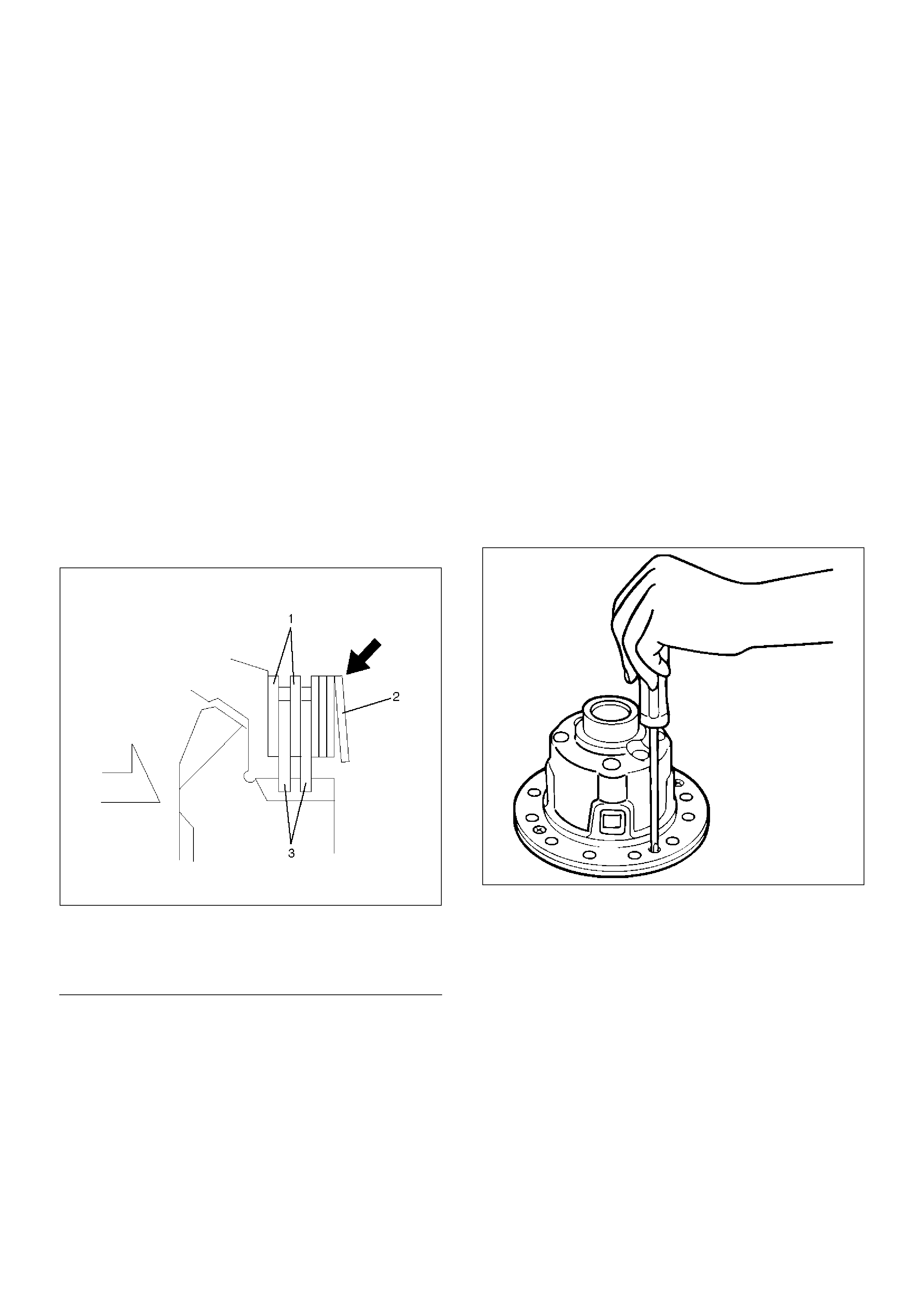
1. Install Differential cage B.
2. Install Thrust washer.
3. Install Spring disc.
• When assembling the spring disc, make sure the
mounting direction is correct as shown in figure.
425RY004
E n dO FC al lo ut
4. Install Friction disc.
5. Install Friction plate.
6. Install Friction plate.
7. Install Friction disc.
8. Install Friction plate.
9. Install Friction disc.
10. Install Friction plate.
11. Install Pressure ring.
12. Install Side gear.
13. Install Pinion and pinion shaft.
14. Install Side gear.
15. Install Pressure ring.
16. Install Friction plate.
17. Install Friction disc.
18. Install Friction plate.
19. Install Friction disc.
20. Install Friction plate.
21. Install Friction plate.
22. Install Friction plate.
23. Install Spring disc.
• When assembling the spring disc, make sure the
mounting direction is correct.
24. Install Spring disc.
25. Install Thrust washer.
26. Install Differential cage A.
27. Install Screw.
• Matching the guide marks of the differential
cages A and B, tighten the screws evenly in the
diagonal order.
425RS055
Thickness: 1.5mm(0.059in)
1.6mm(0.063in)
1.7mm(0.067in)
Legend
(1) Friction Plate
(2) Spring Disc
(3) Friction Disc
28. Check the operation.
• Measure the starting torque using the side gear
holder.
Starting torque:
29–45N·m(3.0–4.6kg·m/22–33Ibft)
425RW065
E n dO FC al lo ut
Legend
(1) Side Gear Holder : 5–8840–2381–0
Main Data and Specifications
General Specifications
Rear axle
Type Banjo, Semi–floating
Rear axle Size 244 mm (9.61 in)
Gear type Hypoid
Gear ratio (to 1) 4.100(6VE1 with A/T)
4.300(6VE1 with M/T,4JX1)
Differential type Pinion (STD), Four pinion (LSD)
Lubricant Grade GL–5: (Standard differential)
GL–5, LSD: (Limited slip differential)
Locking Differential Lubricant 80W90 GL–5 Limited Slip Differential Gear Lubricant
together with Limited Slip Differential Lubricant Additive
(Part No. 8–01052–358–0) or equivalent.
Capacity 3.0 liter (2.6Impqt/3.2 US qt)
Techline
Torque Specifications
420RY00002
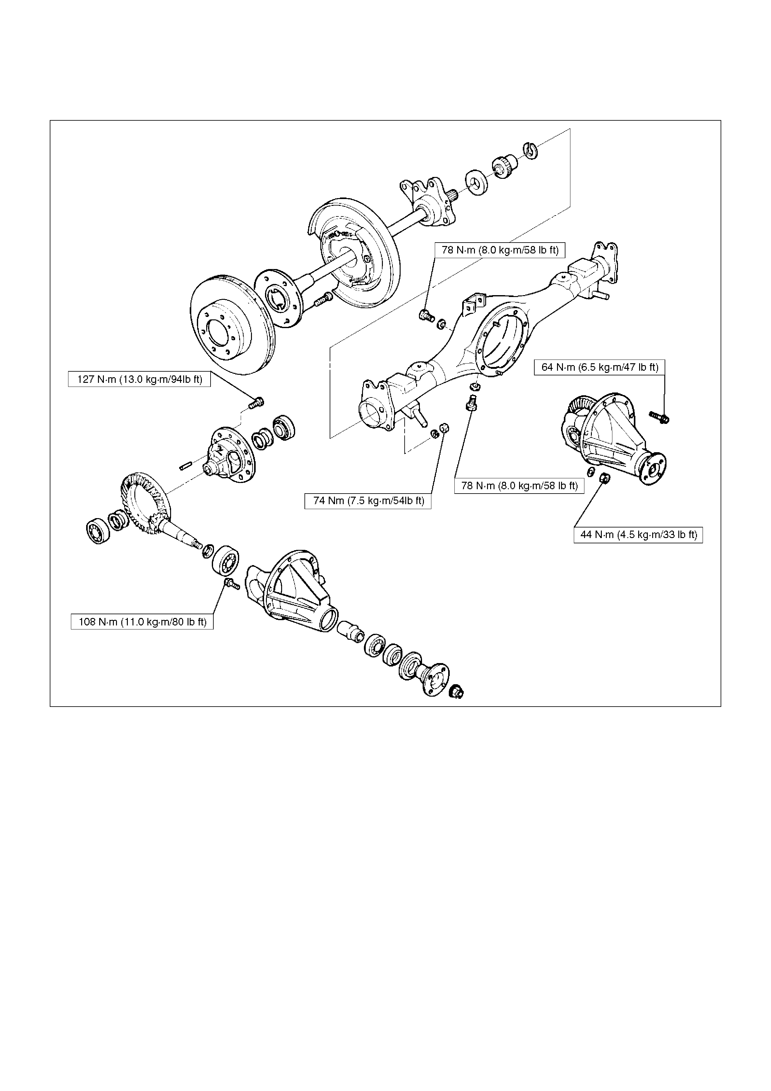
Special Tools
ILLUSTRATION TOOL NO.
TOOL NAME
5–8840–2294–0
(J–39210)
Installer; Axle shaft inner
seal
5–8840–0133–0
(J–8614–01)
Pinion flange holder
5–8840–2165–0
(J–37263)
Installer; Pinion oil seal
5–8840–2029–0
(J–42832)
Holding fixture
5–8840–0003–0
(J–3289–20)
Holding fixture base
5–8840–2587–0
(J–42379)
Remover; Bearing
5–8840–2576–0
(J–8107–3)
Adapter; Side bearing
plug
5–8840–2689–0
(J–44461)
Installer; Outer bearing
outer race
5–8840–0007–0
(J–8092)
Grip
5–8840–2690–0
(J–44462)
Installer; Inner bearing
outer race
5–8840–2681–0
(J–42824)
Pilot;Outer
5–8840–0127–0
(J–21777–43)
Nut & Bolt
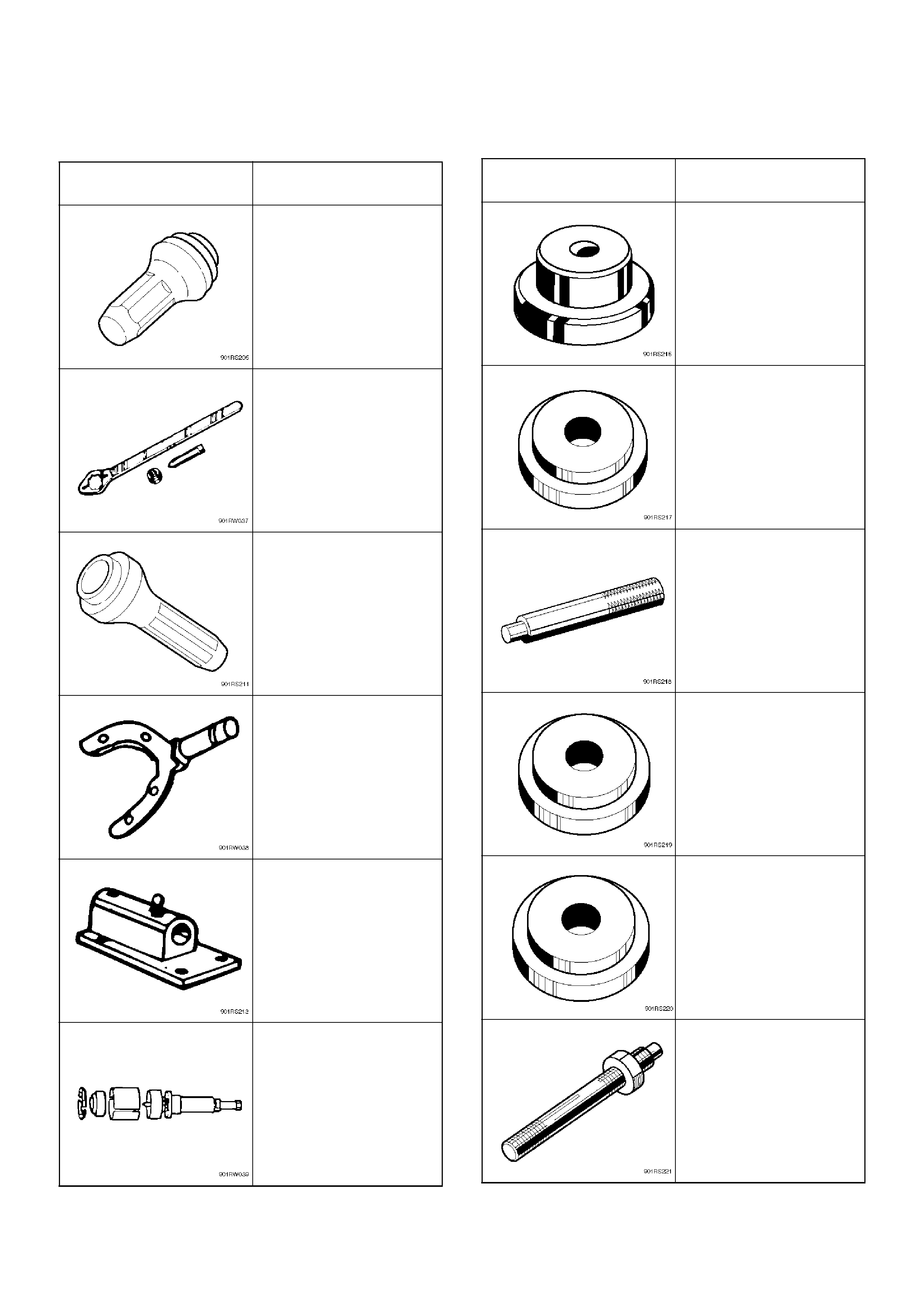
ILLUSTRATION TOOL NO.
TOOL NAME
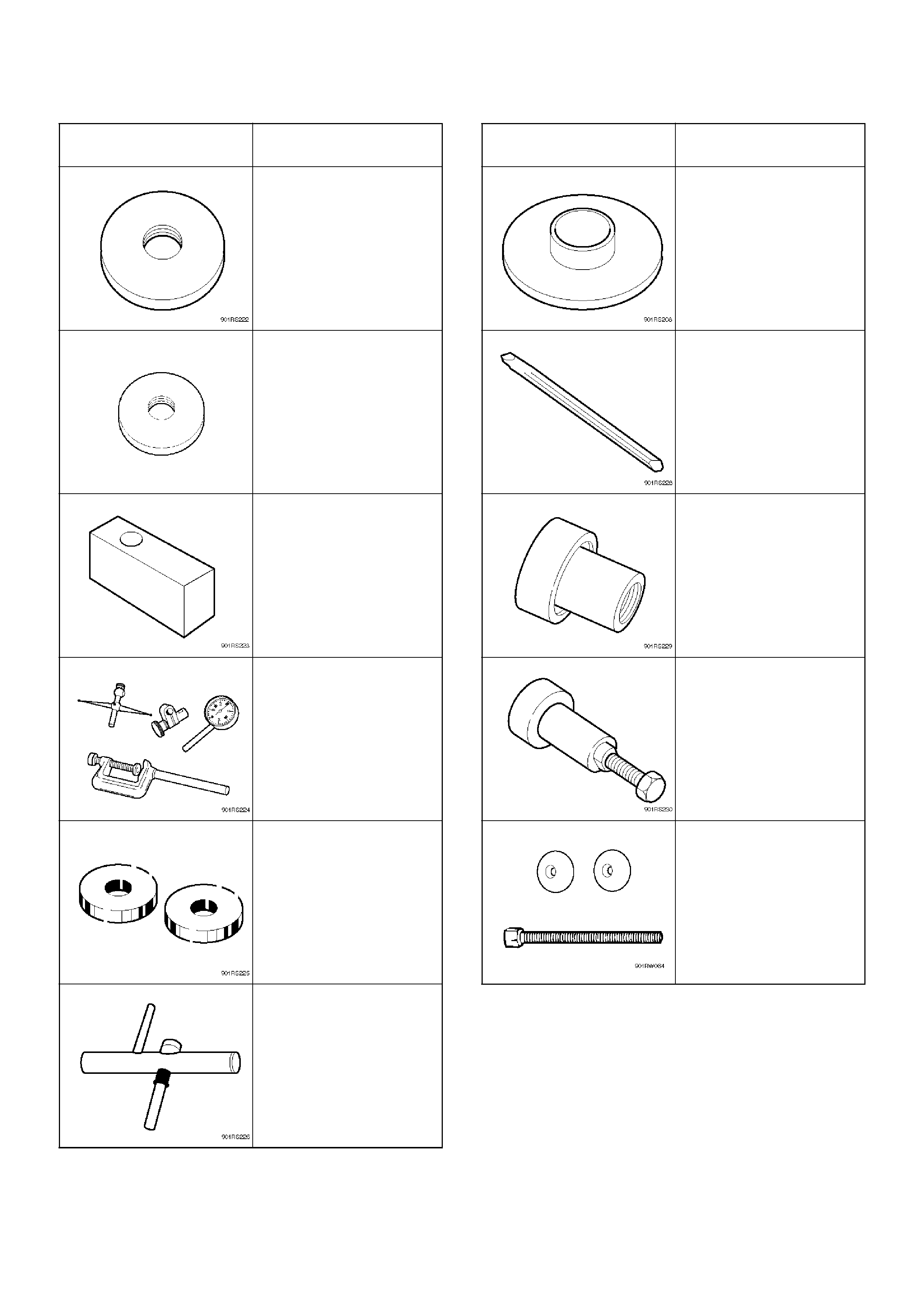
5–8840–2680–0
(J–44453)
Pilot; Inner
5–8840–2681
(J–44449)
Pilot; Outer bearing
5–8840–2678–0
(J–44451)
Gage plate
5–8840–0126–0
(J–8001)
Dial indicator
5–8840–2679–0
(J–44452)
Disc (2 required)
5–8840–0128–0
(J–23597–1)
Arbor
ILLUSTRATION TOOL NO.
TOOL NAME
5–8840–2574–0
(J–42828)
Installer; Pinion bearing
5–8840–2293–0
(J–39209)
Punch; End nut lock
5–8840–2570–0
(J–42829)
Installer; Side bearing
5–8840–2323–0
(J–39602)
Remover; Outer bearing
5–8840–2586–0
(J–39858)
Clutch pack unloading
tool kit Includes
Screw cap, Cap and
Forcing screw
ILLUSTRATION TOOL NO.
TOOL NAME