
SECTION 4D - HUBS, AXLES & DRIVE SHAFTS
Service Precaution
General Description
Diagnosis
Rear Axle Shaft
Rear Axle Shaft and Associated Parts
Removal
Inspection and Repair
Oil Seal Replacement
Installation
Special Tools
Front Hub and Disc (with Shift on the Fly)
Disassembled View
Disassembly
Inspection and Repair
Reassembly
Front Hub and Disc with Manual Locking Hub
Disassembled View
Disassembly
Inspection and Repair
Reassembly
Main Data and Specifications
Torque Specifications
Special Tools
Front Drive Shaft Joint
Front Drive Shaft Joints Replacement
Front Axle Drive Shaft
Front Axle Drive Shaft and Associated Parts
Disassembly
Inspection and Repair
Bushing Replacement
Reassembly
Shift On The Fly System
Shift On The Fly System and Associated Parts
Disassembly
Inspection and Repair
Reassembly
Main Data and Specifications
General Specifications
Torque Specifications
Special Tools
Front Propeller Shaft
General Description
Front Propeller Shaft and Associated Parts
Removal
Installation
Disassembly (Except TOD 4x4)
Universal Joint Disassembly
Inspection and Repair
Universal Joint Reassembly
Reassembly (Except TOD 4x4)
Main Data and Specifications
General Specifications
Torque Specifications
Rear Propeller Shaft
General Description
Rear Propeller Shaft and Associated Parts
Removal
Installation
Disassembly
Universal Joint Disassembly
Inspection and Repair
Universal Joint Reassembly
Reassembly
Main Data and Specifications
General Specifications
Torque Specifications
Techline

Service Precaution
WARNING: IF SO EQUIPPED WITH A
SUPPLEMENTAL RESTRAINT SYSTEM (SRS),
REFER TO THE SRS COMPONENT AND WIRING
LOCATION VIEW IN ORDER TO DETERMINE
WHETHER YOU ARE PERFORMING SERVICE ON
OR NEAR THE SRS COMPONENTS OR THE SRS
WIRING. WHEN YOU ARE PERFORMING SERVICE
ON OR NEAR THE SRS COMPONENTS OR THE
SRS WIRING, REFER TO THE SRS SERVICE
INFORMATION. FAILURE TO FOLLOW WARNINGS
COULD RESULT IN POSSIBLE AIR BAG
DEPLOYMENT, PERSONAL INJURY, OR
OTHERWISE UNNEEDED SRS SYSTEM REPAIRS.
CAUTION: Always use the correct fastener in the
proper location. When you replace a fastener, use
ONLY the exact part number for that application.
HOLDEN will call out those fasteners that require a
replacement after removal. HOLDEN will also call
out the fasteners that require thread lockers or
thread sealant. UNLESS OTHERWISE SPECIFIED ,
do not use supplemental coatings (Paints, greases,
or other corrosion inhibitors) on threaded fasteners
or fastener joint interfaces. Generally, such
coatings adversely affect the fastener torque and
the joint clamping force, and may damage the
fastener. When you install fasteners, use the
correct tightening sequence and specifications.
Following these instructions can help you avoid
damage to parts and systems.
General Description
This publication contains essential removal, installation,
adjustment and maintenance procedures.
The front axle utilizes a central disconnect type front
axle/transfer case system.
The drive axles are completely flexible assemblies,
consisting of inner and outer constant velocity (CV)
drive shaft joints connected by an axle shaft.
For description of propeller shaft and universal joint,
refer to Front / Rear Propeller Shaft in this section.

Diagnosis
Condition Possible Cause Correction
Oil Leak At Front Axle Worn or defective oil seal. Replace the oil seal.
Front axle housing cracked. Repair or replace.
Oil Leak At Pinion Shaft Too much gear oil. Correct the oil level.
Oil seal worn or defective. Replace the oil seal.
Pinion flange loose or damaged. Tighten or replace.
Noises In Front Axle Drive Shaft Joint Broken or worn drive shaft joints and
bellows (BJ and DOJ). Replace the drive shaft joints and
bellows.
“Clank”When Accelerating From
“Coast” Loose drive shaft joint to output shaft
bolts. Tighten.
Damaged inner drive shaft joint. Replace.
Shudder or Vibration During
Acceleration Excessive drive shaft joint angle. Repair.
Worn or damaged drive shaft joints. Replace.
Sticking spider assembly (inner drive
shaft joint). Lubricate or replace.
Sticking joint assembly (outer drive
shaft joint). Lubricate or replace.
Vibration At Highway Speeds Out of balance or out of round tires. Balance or replace.
Front end out of alignment. Align.
Noises in Front Axle Insufficient gear oil. Replenish the gear oil.
Wrong or poor grade gear oil. Replace the gear oil.
Drive pinion to ring gear backlash
incorrect. Adjust the backlash.
Worn or chipped ring gear, pinion
gear or side gear. Replace the ring gear, pinion gear or
side gear.
Pinion shaft bearing worn. Replace the pinion shaft bearing.
Wheel bearing worn. Replace the wheel bearing.
Differential bearing loose or worn. Tighten or replace.
Wanders and Pulls Wheel bearing preload too tight. Adjust the wheel bearing preload.
Incorrect front alignment. Adjust the front alignment.
Steering linkage loose or worn. Tighten or replace.
Steering gear out of adjustment. Adjust or replace the steering gear.
Tire worn or improperly inflated. Adjust the inflation or replace.
Front or rear suspension parts loose
or broken. Tighten or replace.

Front Wheel Shimmy Wheel bearing worn or improperly
adjusted. Adjust or replace.
Incorrect front alignment. Adjust the front alignment.
Worn ball joint or bush. Replace the ball joint or bush.
Steering linkage loose or worn. Tighten or replace.
Steering gear out of adjustment. Tighten or replace.
Tire worn or improperly inflated. Replace or adjust the inflation.
Shock absorber worn. Replace the shock absorber.
Condition Possible Cause Correction
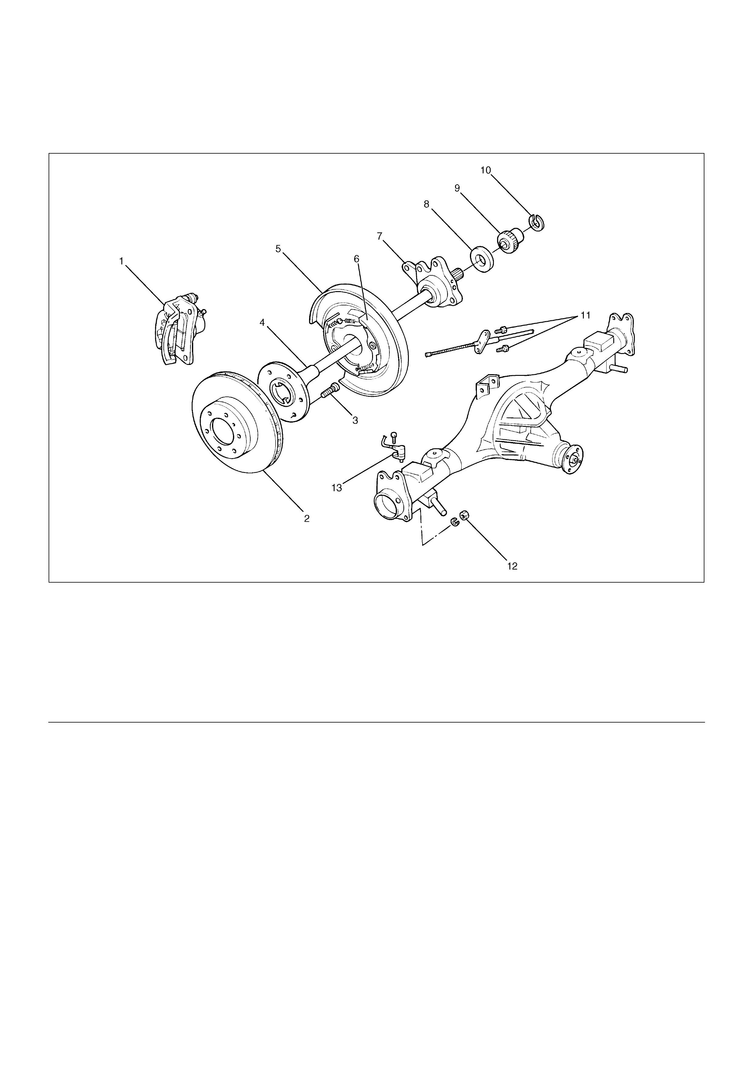
Rear Axle Shaft
Rear Axle Shaft and Associated Parts
420RW014
EndOFCallout
Removal
1.Raise the vehicle.
2.Remove tires and wheels. Refer to Wheel in
Steering section.
3.Remove brake caliper. Use a wire to attach the
brake caliper to the frame. Refer to Disc Brakes in
Brake section.
4. Remove brake disc.
5. Remove ABS sensor (if so equipped).
6.Remove Parking brake assembly. Refer to Parking
Brakes in Brake section.
Legend
(1) Brake Caliper
(2) Brake Disc
(3) Wheel Pin
(4) Axle Shaft Assembly
(5) Back Plate
(6) Parking Brake Assembly
(7) Bearing Holder
(8) Bearing
(9) Retainer
(10) Snap Ring
(11) Bolt
(12) Nut
(13) Antilock Brake System (ABS) Speed Sensor (if
so equipped)
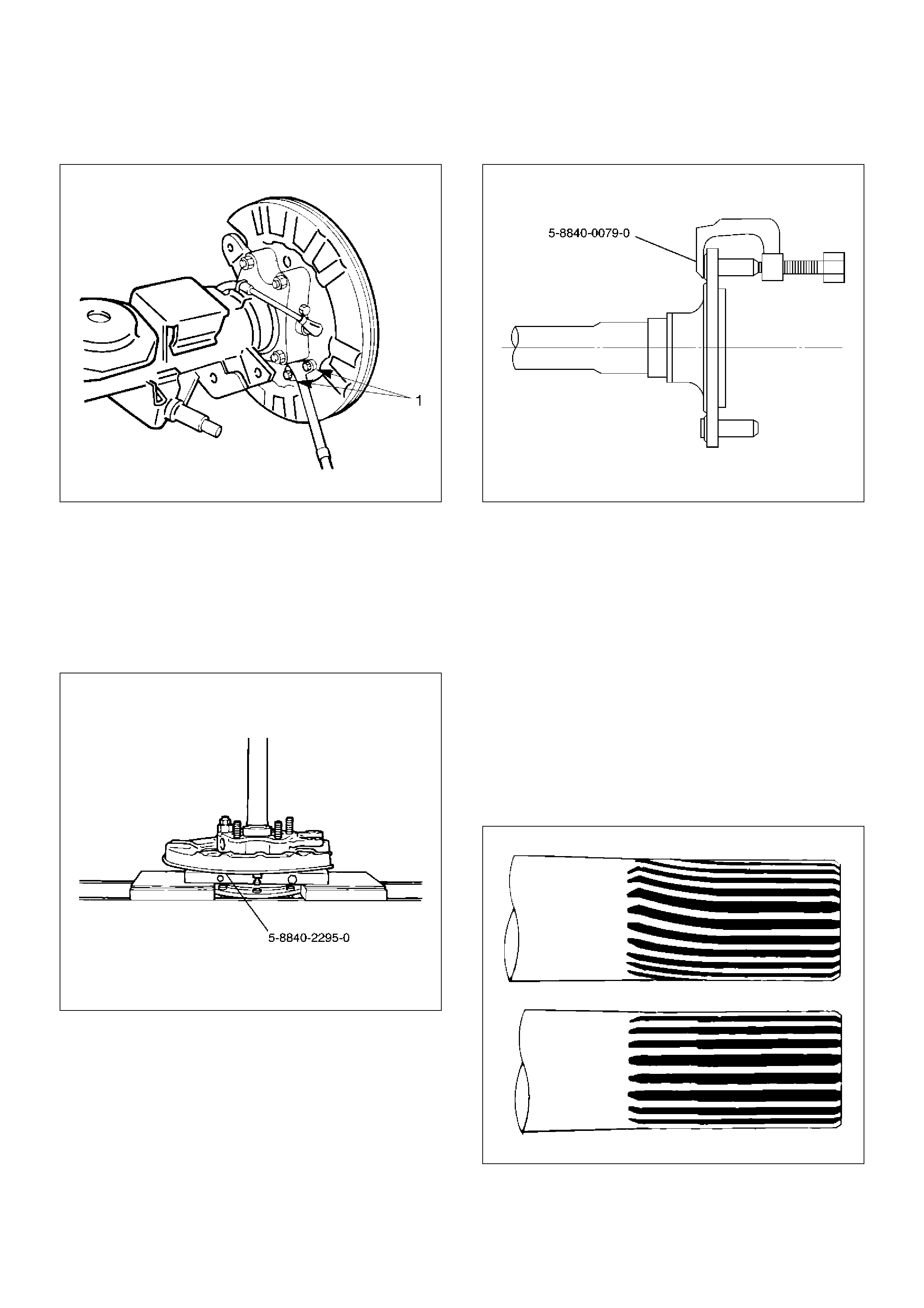
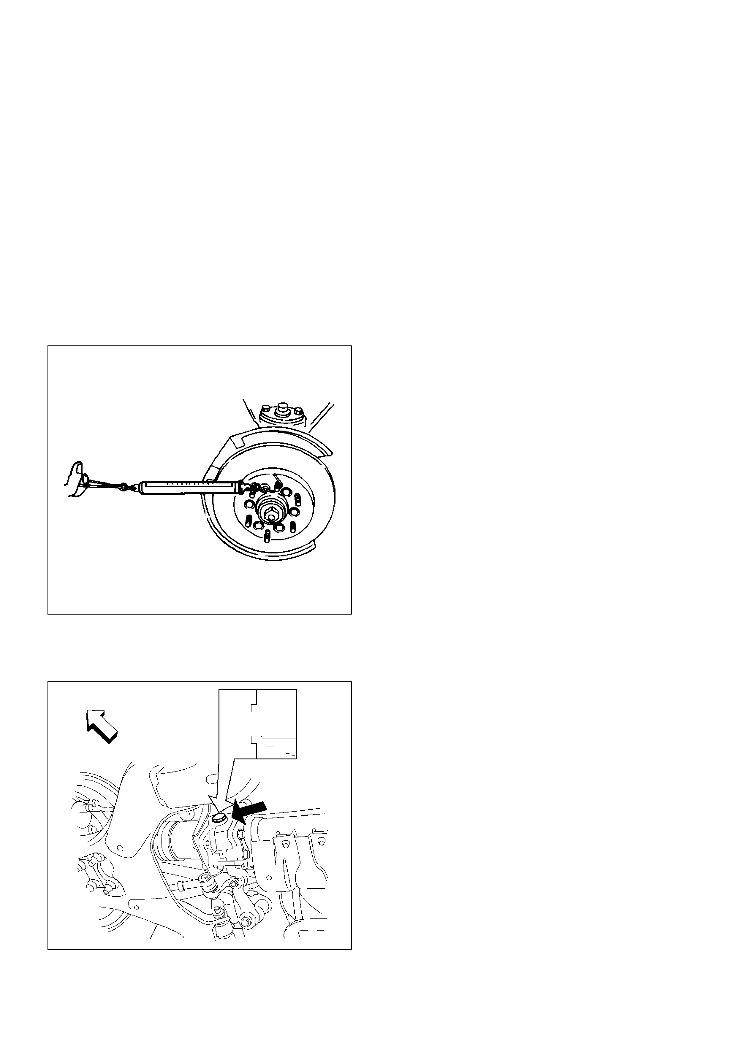
7. Remove the parking brake cable mounting
bolts(Behind the back plate)(1).
311RS001
8. Remove the bearing holder mounting nuts.
9. Remove axle shaft assembly.
NOTE: Be sure not to damage the oil seal.
10. Remove snap ring.
11. Using a bearing remover 5–8840–2295–0 and
press, remove retainer together with the bearing
holder.
420RW024
12. Remove bearing.
13. Remove bearing holder.
14. Remove back plate.
15. Remove the wheel pins using a remover 5–8840–
0079–0.
420RW023
Inspection and Repair
Make necessary correction or parts replacement if wear,
corrosion or any other abnormal conditions are found
through inspection.
Visual Check:
Check the following parts for wear, damage, noise or
any other abnormal conditions:
1. Axle shaft
2. Bearing
When checking the axle shaft, pay special attention to
the splined portions and replace the shaft if distortion or
step wear is noticeable. Correct slight step wear with a
grinder.
420RS008
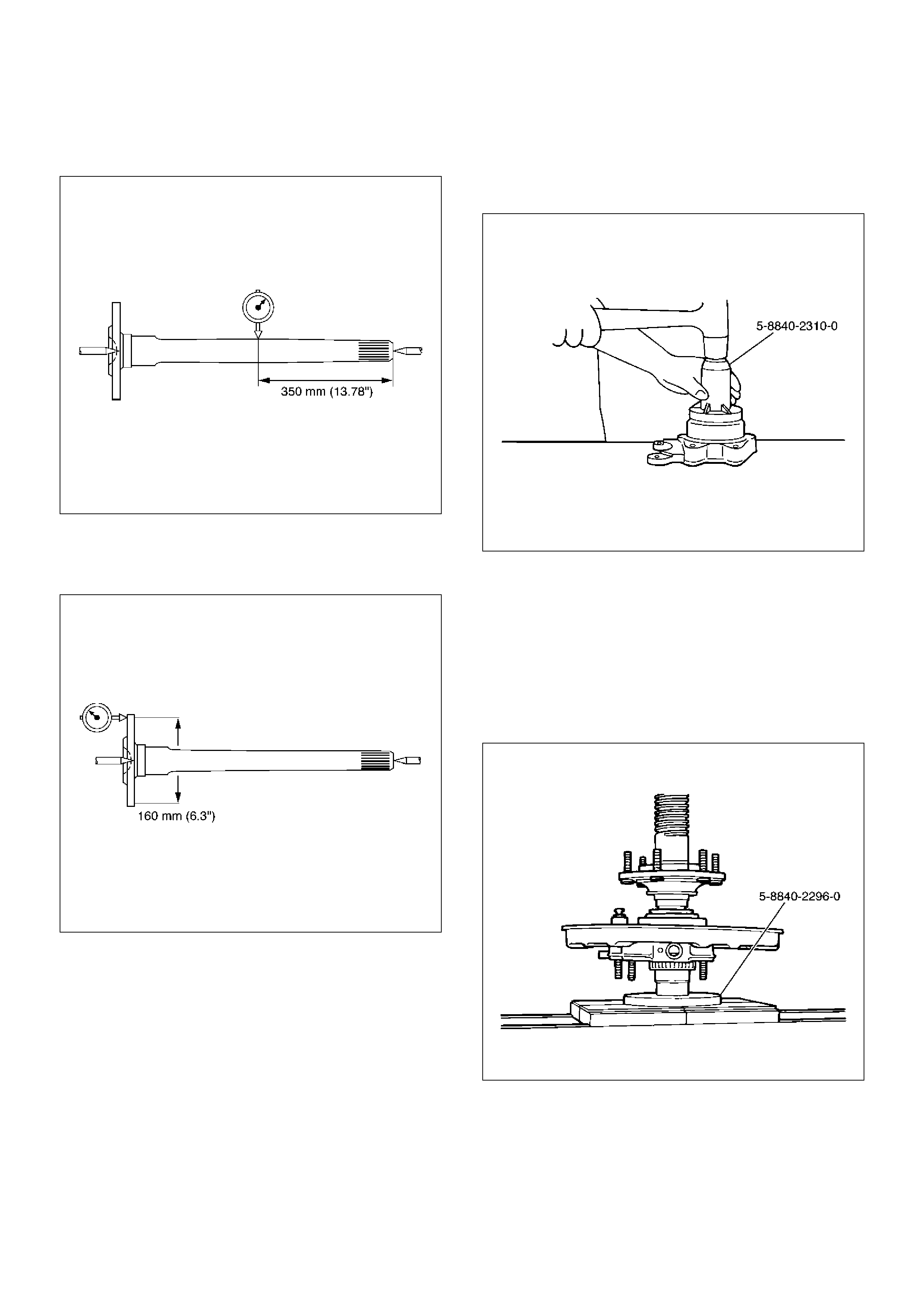
Axle Shaft Run–out
Limit: 1.0 mm (0.039 in)
420RW025
Axle Shaft Flange Run–out
Limit: 0.08 mm (0.003 in)
420RS010
Oil Seal Replacement
Remove the oil seal carefully not to damage the bearing
holder bore .
When installing, use oil seal installer 5–8840–2310–0.
420RW026
Installation
1. Install wheel pin.
2. Install back plate.
3. Install bearing holder.
4. Install bearing.
5. Install retainer by using a bearing installer 5–8840–
2296–0, press fit together with the bearing.
420RW027
6. Install snap ring.
7. Install axle shaft assembly.
NOTE: Be sure not to damage the oil seal.
8. Tighten the bearing holder mounting nut to the
specified torque.
Torque: 74N·m (7.5kg·m/54 Ib ft)

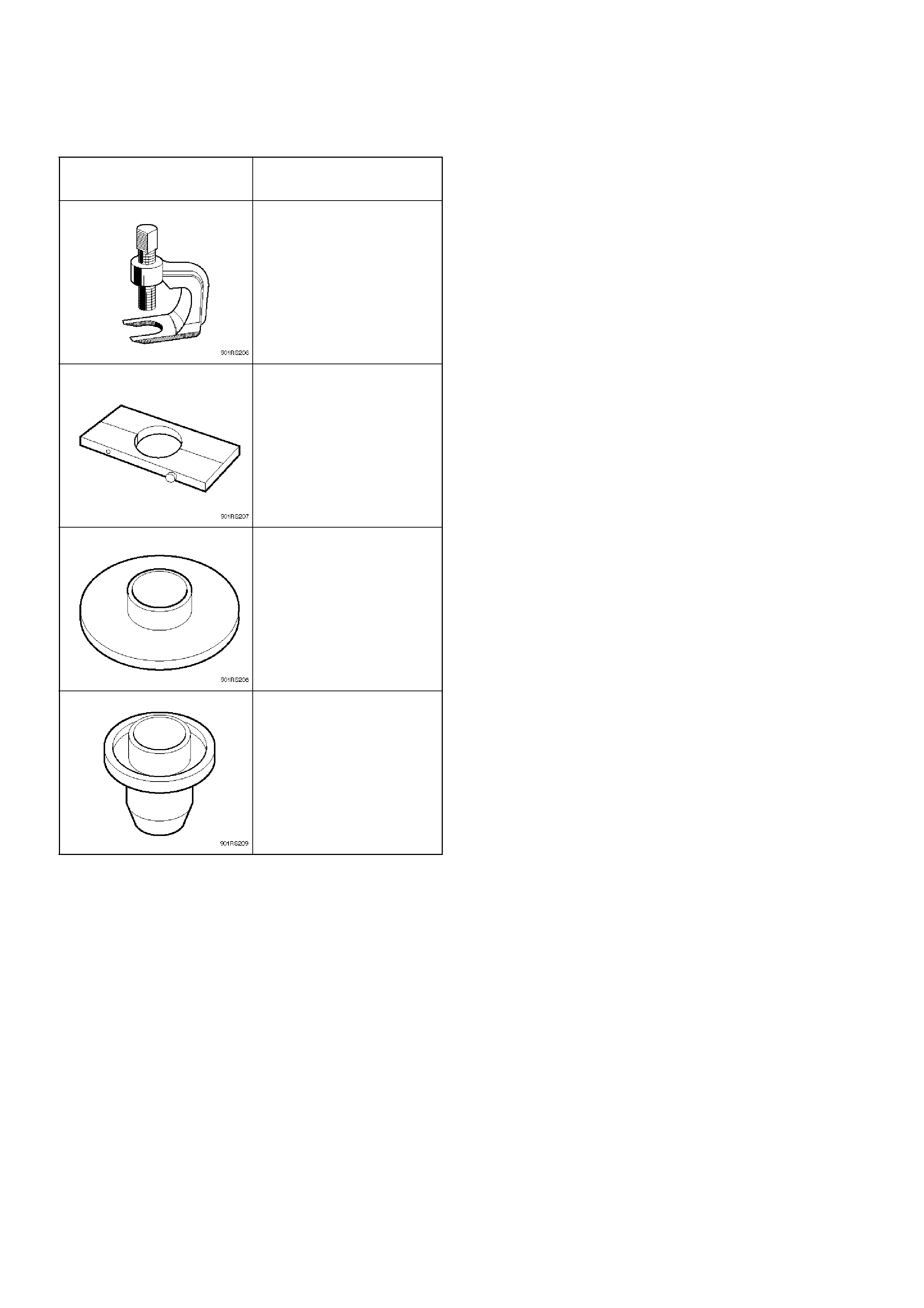
Special Tools
ILLUSTRATION TOOL NO.
TOOL NAME
5–8840–0079–0
(J–6627–A)
Wheel pin remover
5–8840–2295–0
(J–39211)
Remover; Axle shaft
bearing
5–8840–2296–0
(J–39212)
Installer; Axle shaft
bearing
5–8840–2310–0
(J–39379)
Installer; Outer axle seal
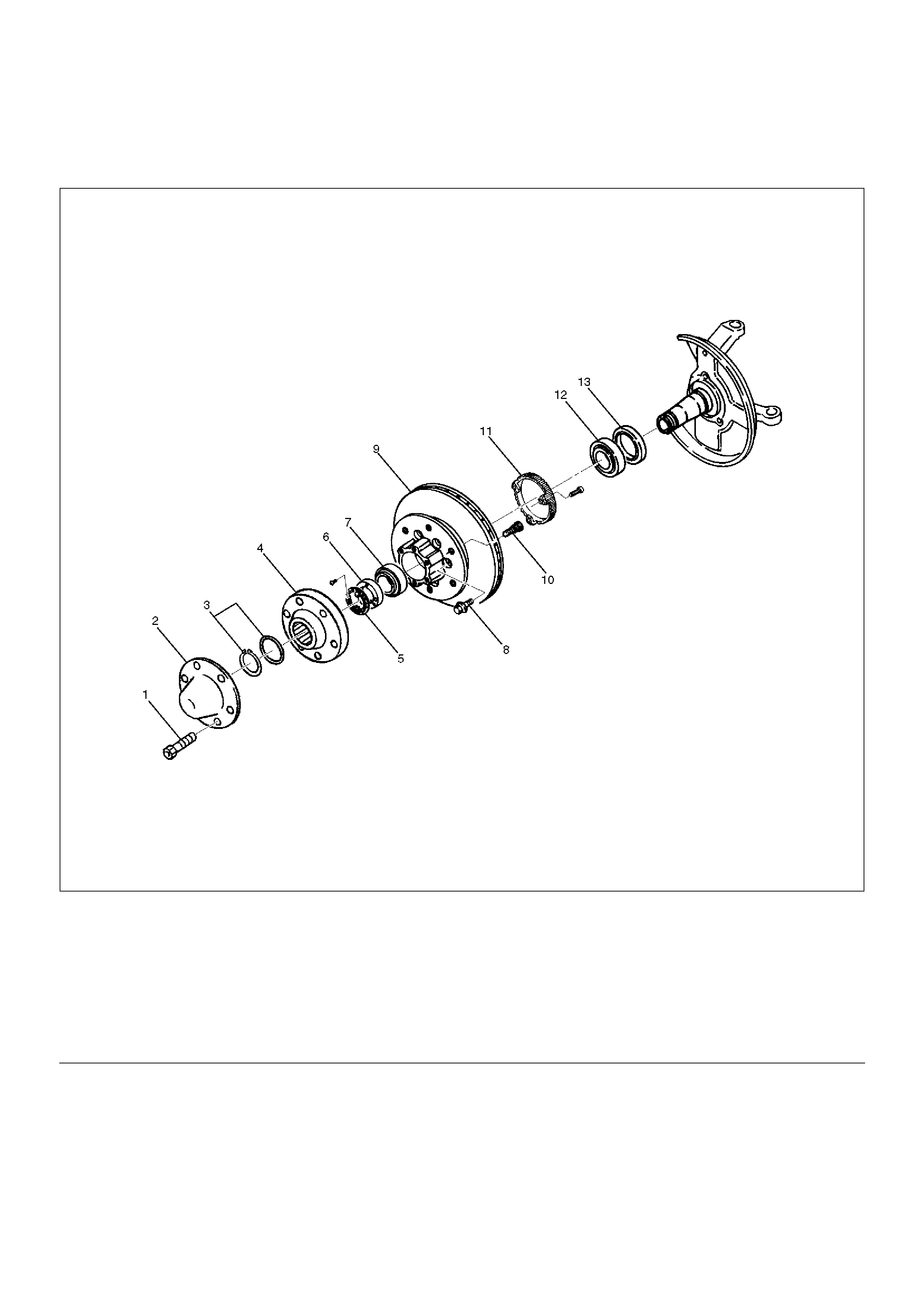
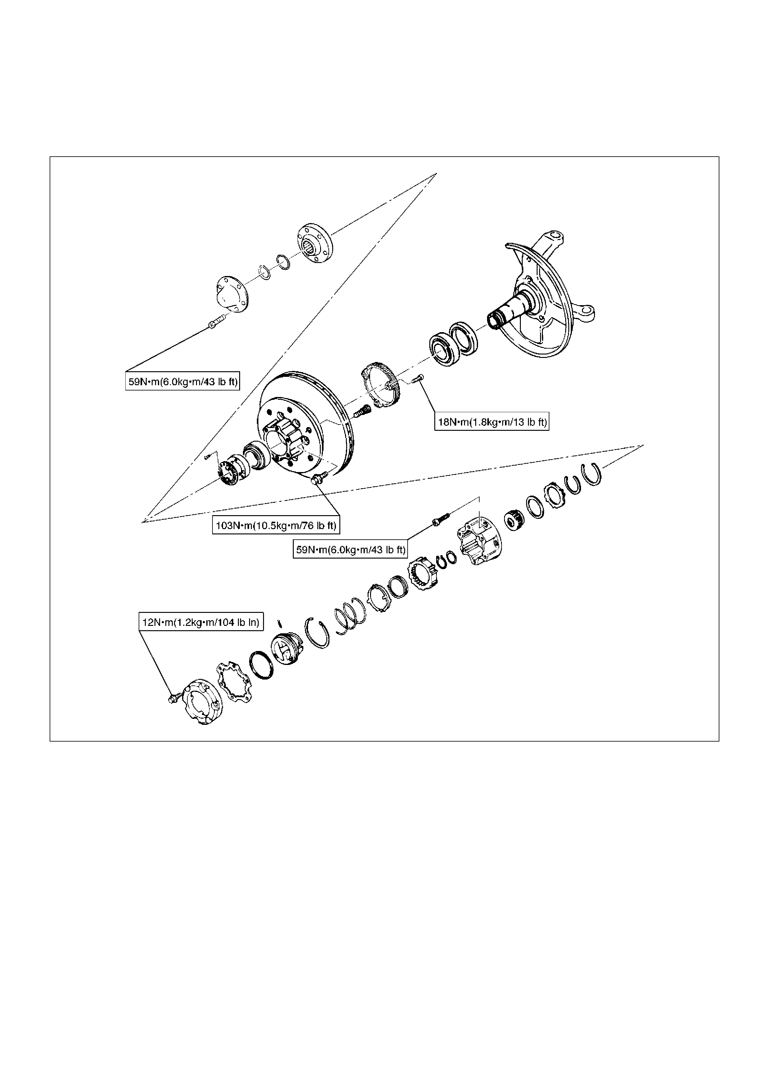
Front Hub and Disc (with Shift on the Fly)
Disassembled View
411RW001
EndOFCallout
Disassembly
1.Before disassembly, select the 2WD position.
2.Jack up the front of vehicle and support frame with
jack stands.
3.Remove the disc brake caliper assembly and hang it
on the frame with wires. Refer to Front Disc Brake
Caliper Assembly in Brakes section.
4. Remove bolt.
5. Remove cap.
6. Remove snap ring and shim.
7. Remove hub flange.
Legend
(1) Bolt
(2) Cap
(3) Snap Ring and Shim
(4) Hub Flange
(5) Lock Washer and Lock Screw
(6) Hub Nut
(7) Outer Bearing
(8) Bolt
(9) Hub and Disc Assembly
(10) Wheel Pin
(11) ABS Sensor Ring (If equipped)
(12) Inner Bearing
(13) Oil Seal
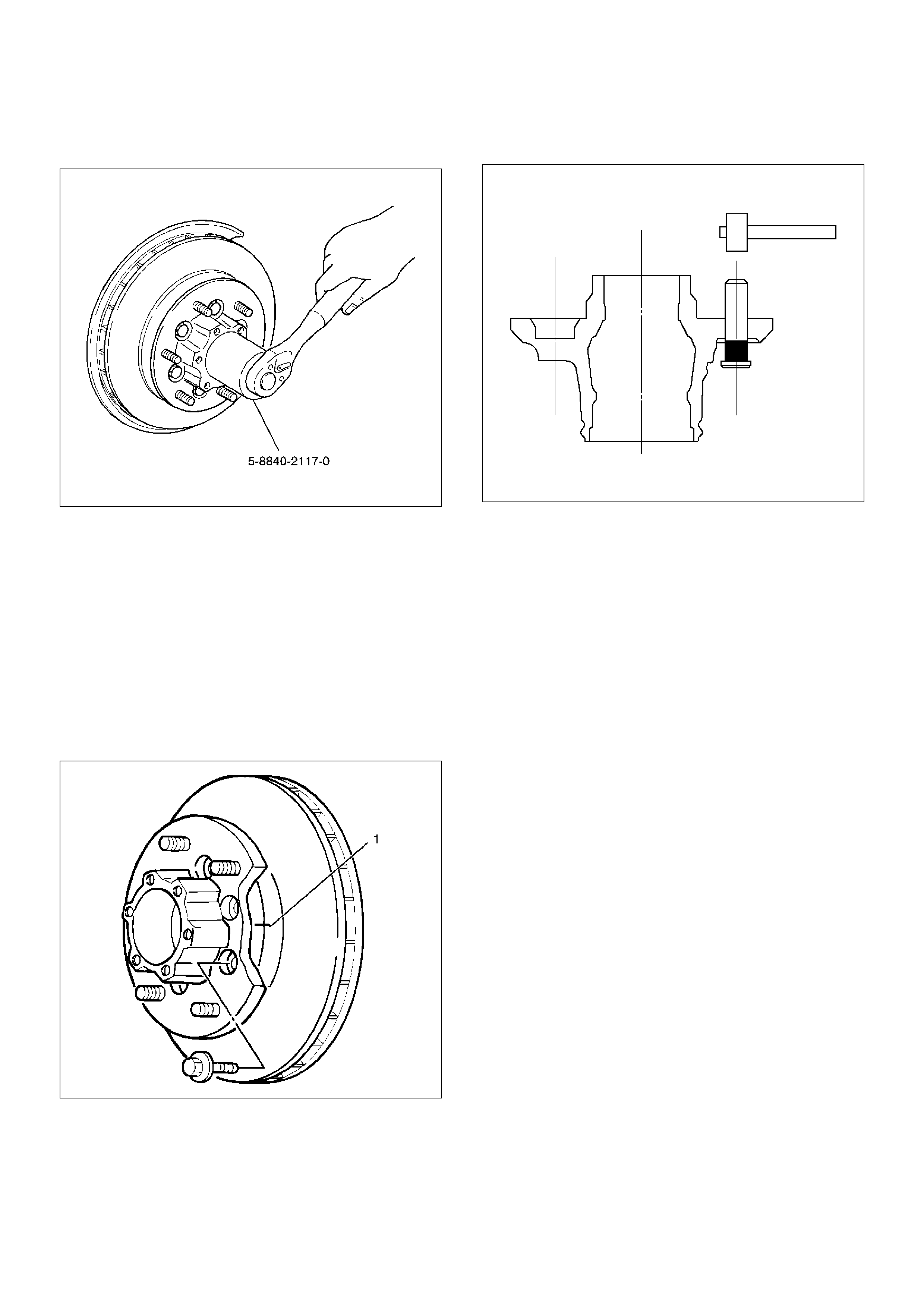
8.Remove lock washer and lock screw.
9.Use wrench 5–8840–2117–0, remove hub nut.
411RW005
10.Remove hub and disc assembly.
11.Remove ABS sensor ring (If equipped).
12.Remove outer bearing.
13.Remove oil seal.
14.Remove inner bearing.
15.Remove bolt , if necessary, replace the wheel pin in
the following manner.
•Apply a scribe mark(1) to disc to hub.
•Clamp the hub and disc assembly in a vise, using
protective pads. Remove the 6 disc–to–hub
retaining bolts.
411RS003
•Place hub on a suitable work surface and remove
the studs by using a hammer.
411RS004
Inspection and Repair
Make necessary correction or parts replacement if wear,
damage, corrosion or any other abnormal conditions are
found through inspection.
Check the following parts:
•Hub
•Hub bearing oil seal
•Knuckle spindle
•Disc
•Caliper
•Shift on the fly system parts (Cap, Hub flange, Shim,
Snap ring)
•ABS sensor ring (If equipped)
For inspection and servicing of disc caliper and related
parts, refer to Brakes section.
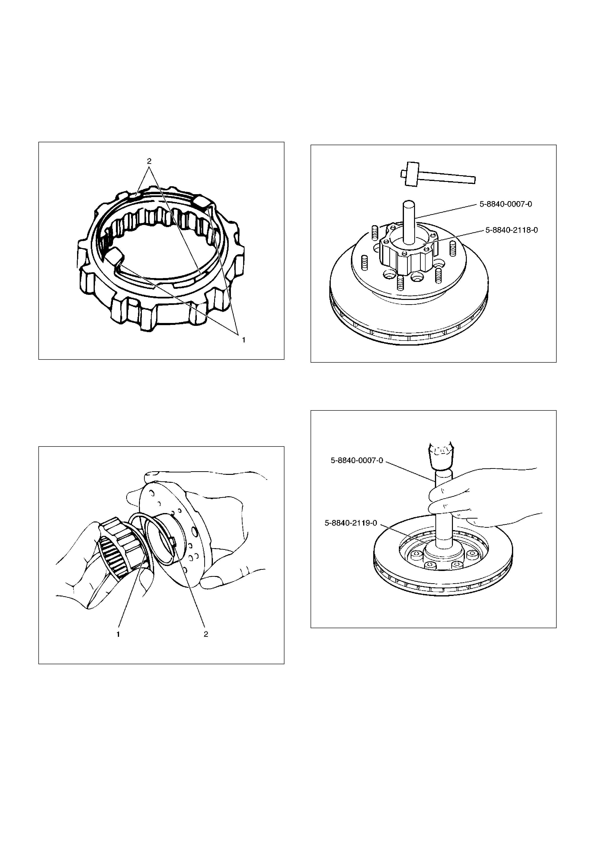
Reassembly
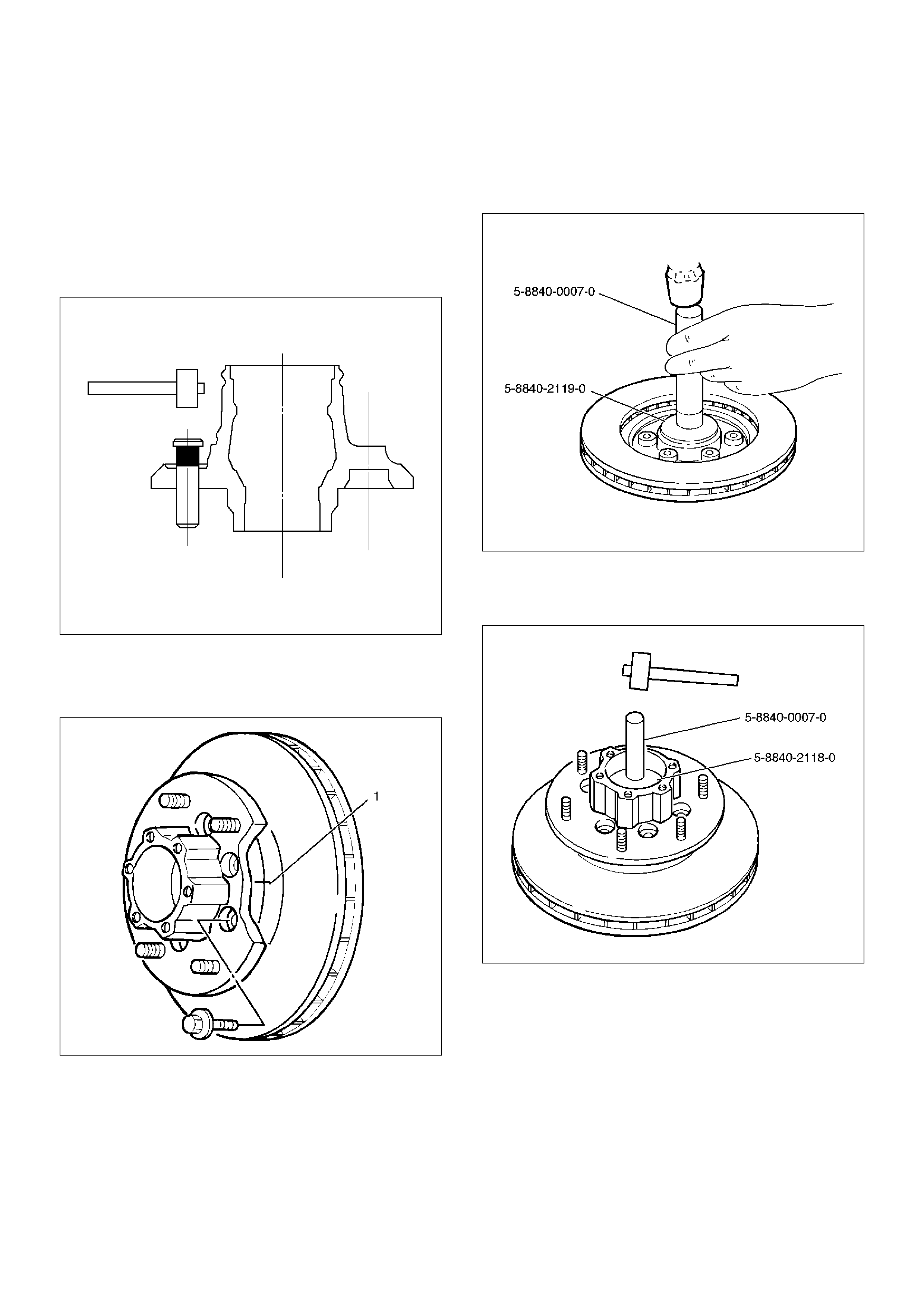
1. Install wheel pin.
• Place the hub on a wood workbench or a block of
wood approx. 6" by 6" to protect the wheel stud
ends and threads.
• Insert a wheel stud using a hammer.
Be sure the wheel stud is started squarely and
seats completely.
411RS005
2. Align scribe marks(1) and attach the hub to the disc,
then tighten the bolts to the specified torque.
Torque: 103N·m(10.5kg·m/76lbft)
411RS003
3. Use installer 5–8840–2119–0 and grip 5–8840–
0007–0, then install the inner bearing by driving it
into the hub.
411RW006
4. Use installer 5–8840–2118–0 and grip 5–8840–
0007–0, then install the outer bearing by driving it
into the hub.
411RW007
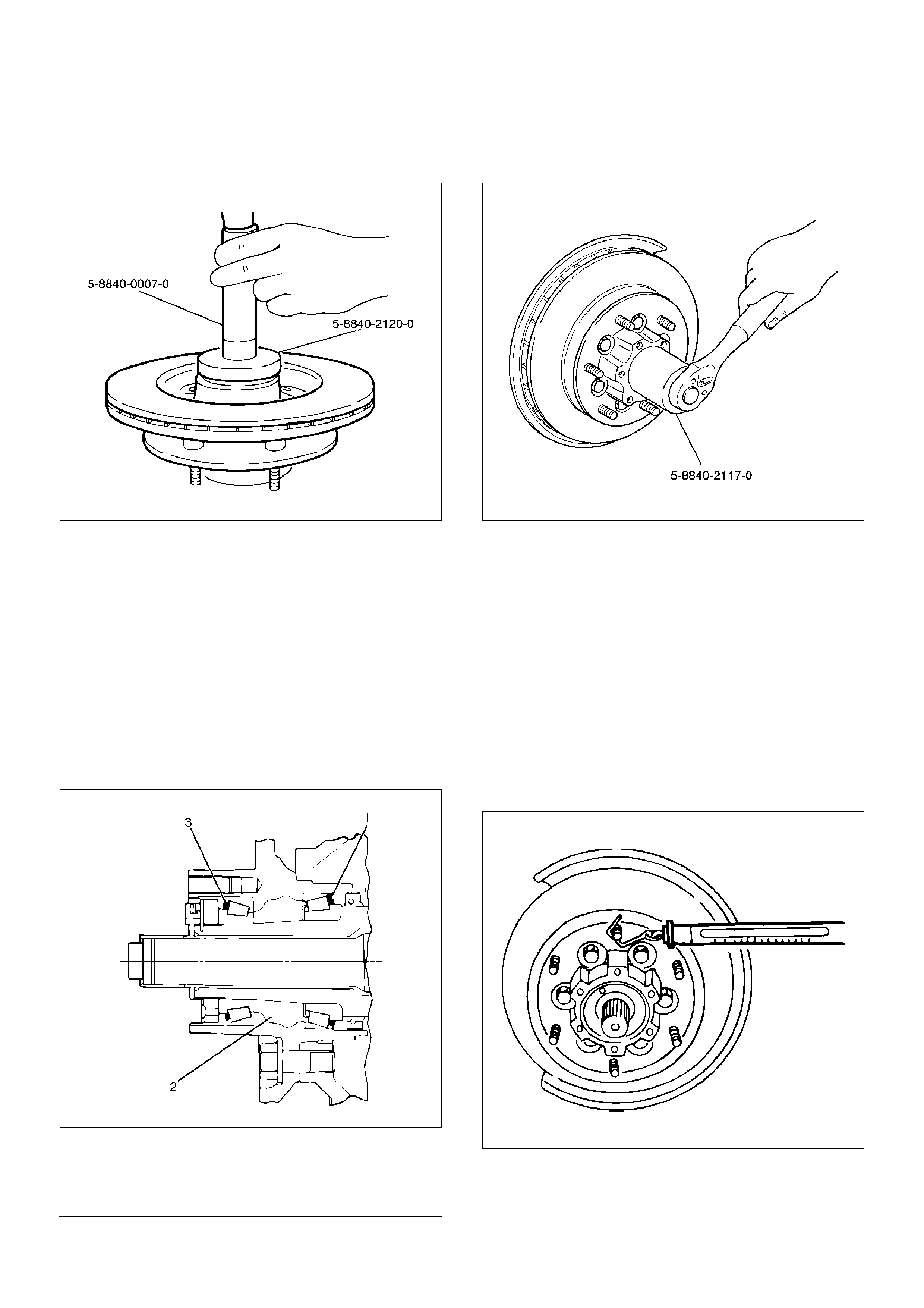
5. Apply grease (NLGI No.2 or equivalent) to the lip
portion, then install oil seal by using installer 5–
8840–2120–0 and grip 5–8840–0007–0.
411RW008
6. Install ABS sensor ring, then tighten the bolts to the
specified torque.
Torque: 18N·m (1.8kg·m/13lbft)
7. Install hub and disc assembly.
• Apply grease in the hub.
• Apply wheel bearing type grease NLGI No. 2 or
equivalent to the outer and inner bearing.
Grease Amount
Hub: 35 g (1.23oz)
Outer bearing: 10g (0.35oz)
Inner bearing: 15g (0.53oz)
411RS009
EndOFCallout
8. Install hub nut. Turn the place where there is a
chamfer in the tapped hole to the outer side, then
attach the nut by using front hub nut wrench 5–
8840–2117–0.
411RW005
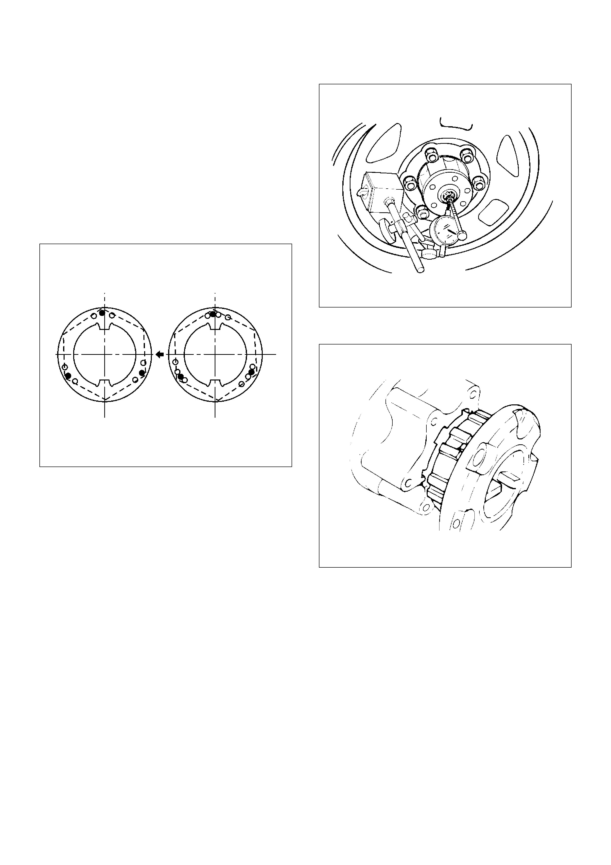
Preload Adjustment
1. Tighten the hub nut to 29 N·m (3.0kg·m/22lbft),
then fully loosen the nut.
2. Tighten the hub nut to the value given below,
using a spring scale on the wheel pin.
New bearing and New oil seal
Bearing Preload: 20 – 25N (2.0–2.5kg/4.4– 5.5lb)
Used bearing and New oil seal
Bearing Preload: 12 – 18N (1.2–1.8kg/2.6– 4.0lb)
If the measured bearing preload is outside the
specifications, adjust it by loosening or tightening
the bearing nut.
411RS011
Legend
(1) Inner Bearing
(2) Hub
(3) Outer Bearing
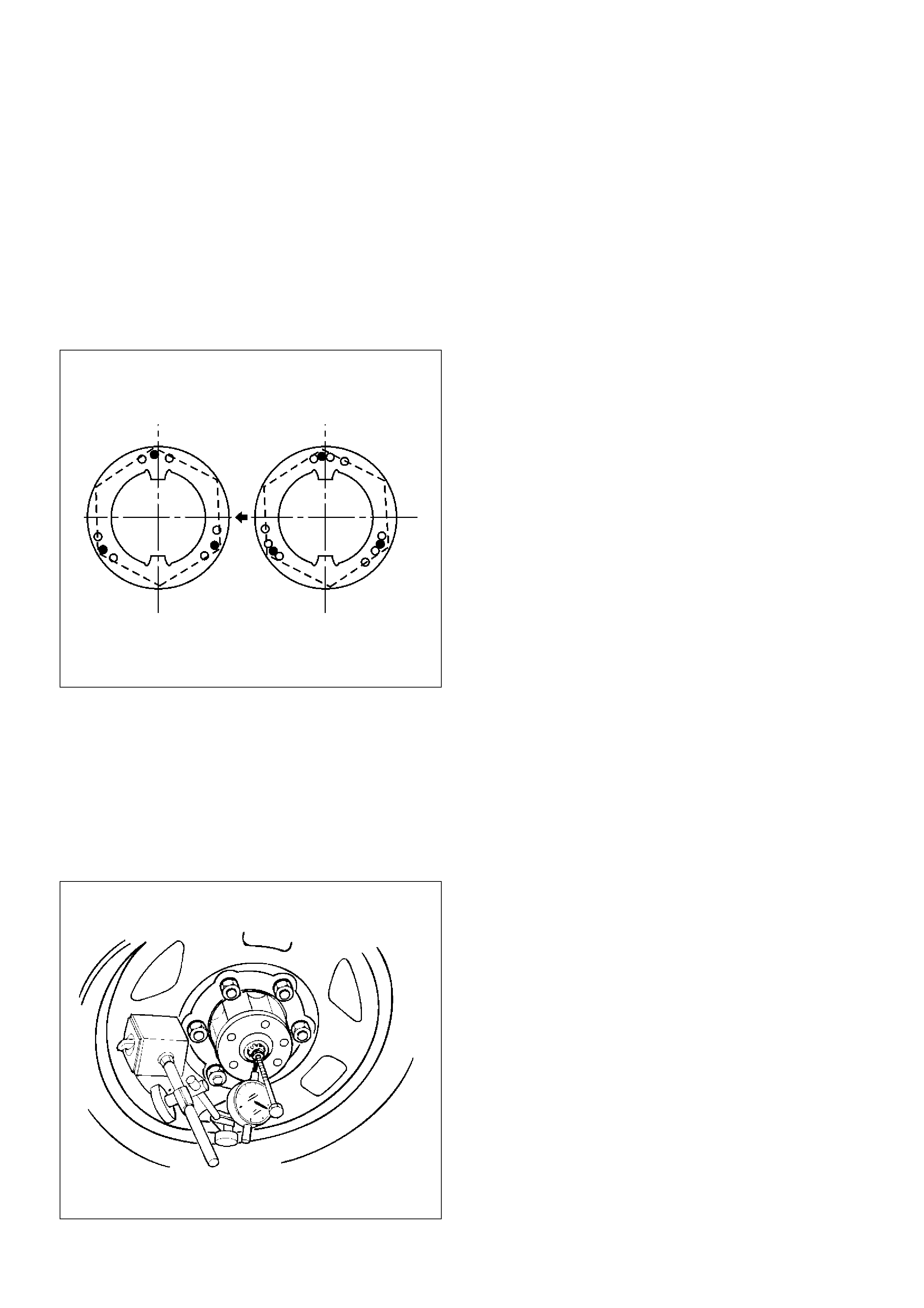
9. Install lock washer and lock screw in the following
manner.
• Turn the side with larger diameter of the tapered
bore to the vehicle outer side, then attach the
washer.
• If the bolt holes in the lock plate are not aligned
with the corresponding holes in the nut, reverse
the lock plate.
• If the bolt holes are still out of alignment, turn in
the nut just enough to obtain alignment.
• Screw is to be fastened tightly so its head may
come lower than the surface of the washer.
411RS012
10. Apply adhesive (LOCTITE 515 or equivalent) to
both joining flange faces then install hub flange.
11. Install snap ring and shim.
• Adjust the clearance between the free wheeling
hub body and the snap ring.
Clearance: 0mm–0.3mm (0in–0.012in)
Shims Available: 0.2mm, 0.3mm, 0.5mm, 1.0mm
(0.008in, 0.012in, 0.020in, 0.039in)
411RW002
12. Install hub cap.
13. Tighten the bolts to the specified torque.
Torque: 59N·m (6.0kg·m/43lbft)
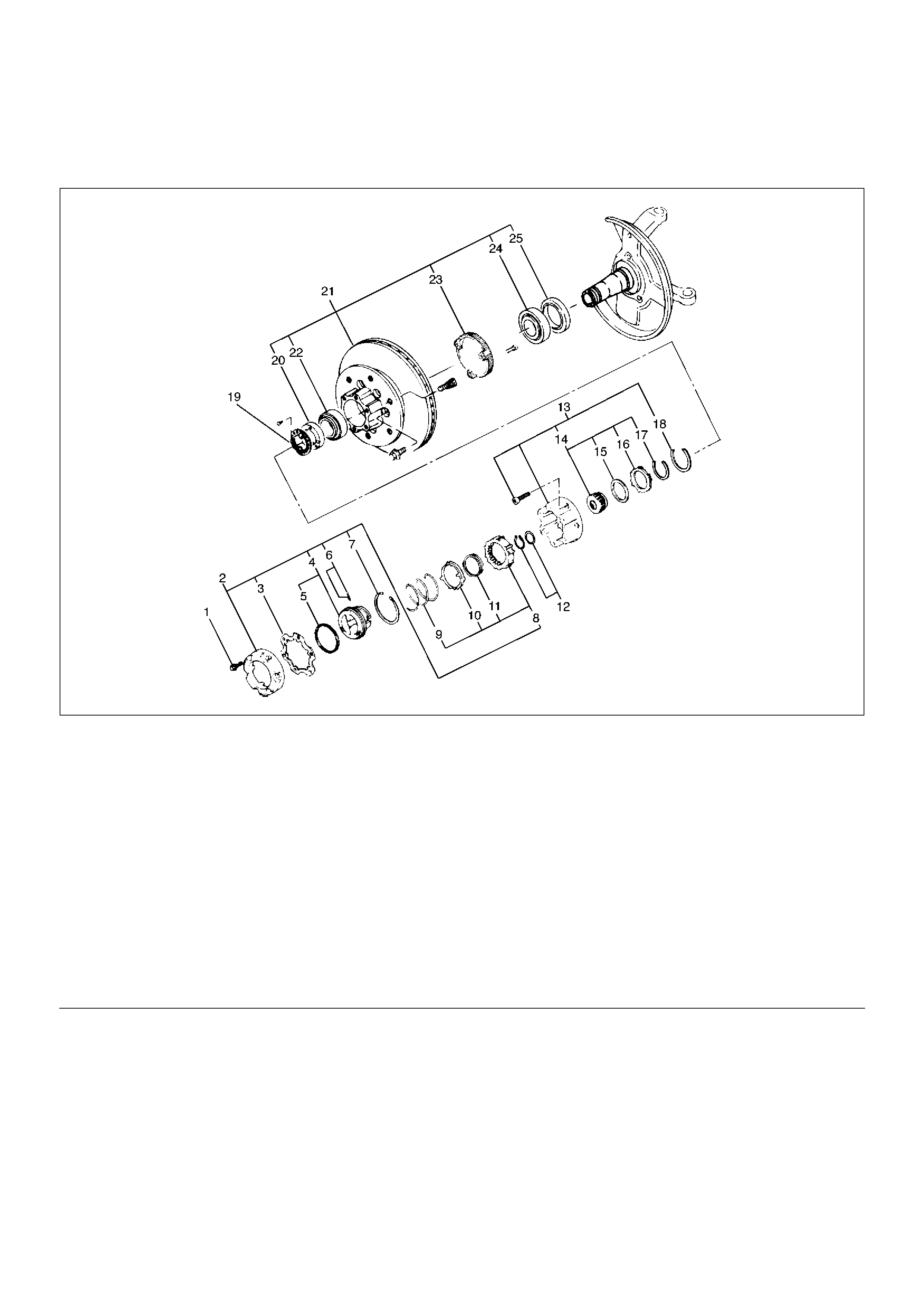
Front Hub and Disc with Manual Locking Hub
Disassembled View
411RW009
EndOFCallout
Disassembly
1.Before disassembly, jack up the front of vehicle and
support frame with jack stands.
2.Remove the disc brake caliper assembly and hang it
on the frame with wires. Refer to Front Disc Brake
Caliper Assembly in Brakes section.
Legend
(1) Bolt
(2) Cover Assembly
(3) Gasket
(4) Knob
(5) X–ring
(6) Detent Ball and Spring
(7) Snap Ring
(8) Clutch Assembly
(9) Compression Spring
(10) Follower
(11) Retaining Spring
(12) Snap Ring and Shim
(13) Body Assembly
(14) Inner Assembly
(15) Spacer
(16) Ring
(17) Snap Ring
(18) Snap Ring
(19) Lock Washer and Lock Screw
(20) Hub Nut
(21) Hub and Disc Assembly
(22) Outer Bearing Outer Race
(23) ABS Sensor Ring (if so equipped)
(24) Inner Bearing Outer Race
(25) Oil Seal
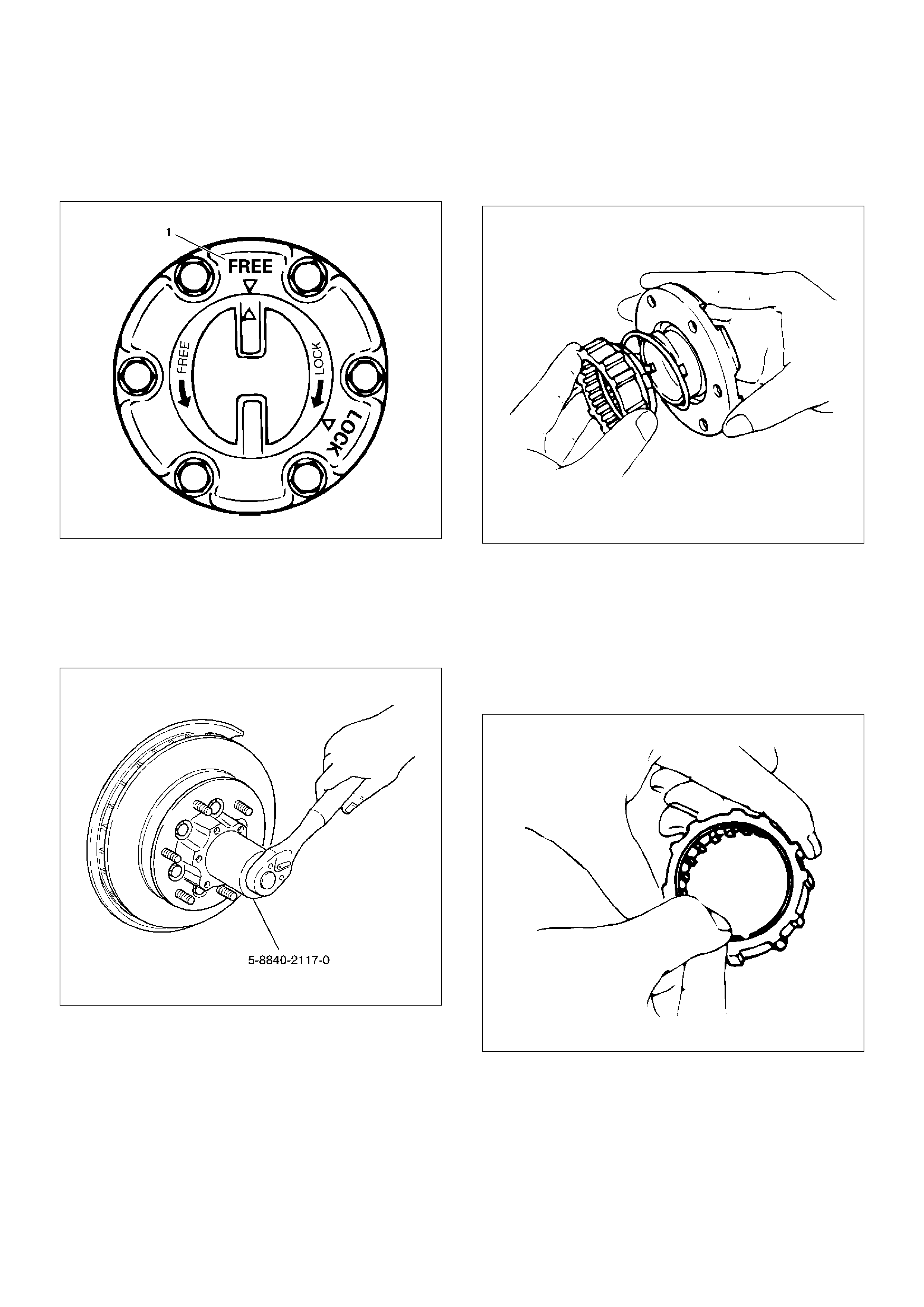
3. Remove bolt.
Before removal, shift transfer lever into “2H”
position, set free wheeling hub knob into “FREE”
position (1), and run the vehicle about 50m (160 ft).
411RW010
4. Remove cover assembly.
5. Remove snap ring and shim.
6. Remove body assembly.
7. Remove lock washer and lock screw.
8. Remove hub nut by using wrench 5–8840–2117–0.
411RW005
9. Remove hub and disc assembly.
10. Remove ABS sensor ring (If equipped).
11. Remove outer bearing outer race.
12. Remove oil seal.
13. Remove inner bearing outer race.
14. While pushing follower knob against cover, turn
clutch assembly clockwise and then remove clutch
assembly from knob.
411RW011
15. Remove gasket.
16. Remove snap ring.
17. Remove knob.
18. Remove compression spring.
19. Remove follower.
20. Remove retaining spring from clutch assembly by
turning it counterclockwise.
411RW012
21. Remove dedent ball and spring.
22. Remove X–ring.
23. Remove snap ring.
24. Remove inner assembly.
25. Remove snap ring.
26. Remove ring.
27. Remove spacer.
Inspection and Repair
Make necessary correction or parts replacement if wear,
damage, corrosion or any other abnormal condition are
found through inspection.
Check the following parts.
•Hub
•Hub bearing, oil seal
•Knuckle spindle
•Disc
•Caliper
•Free wheeling hub parts (Clutch, knob, follower,
inner, ring and spring)
•ABS sensor ring (if so equipped)
For inspection and servicing of disc caliper, and relative
parts, refer to Brakes section.
Reassembly
1. Install spacer.
Apply about 1 g wheel bearing grease to both face
of spacer.
2. Install ring.
Apply about 3 g wheel bearing grease to inside face
of ring.
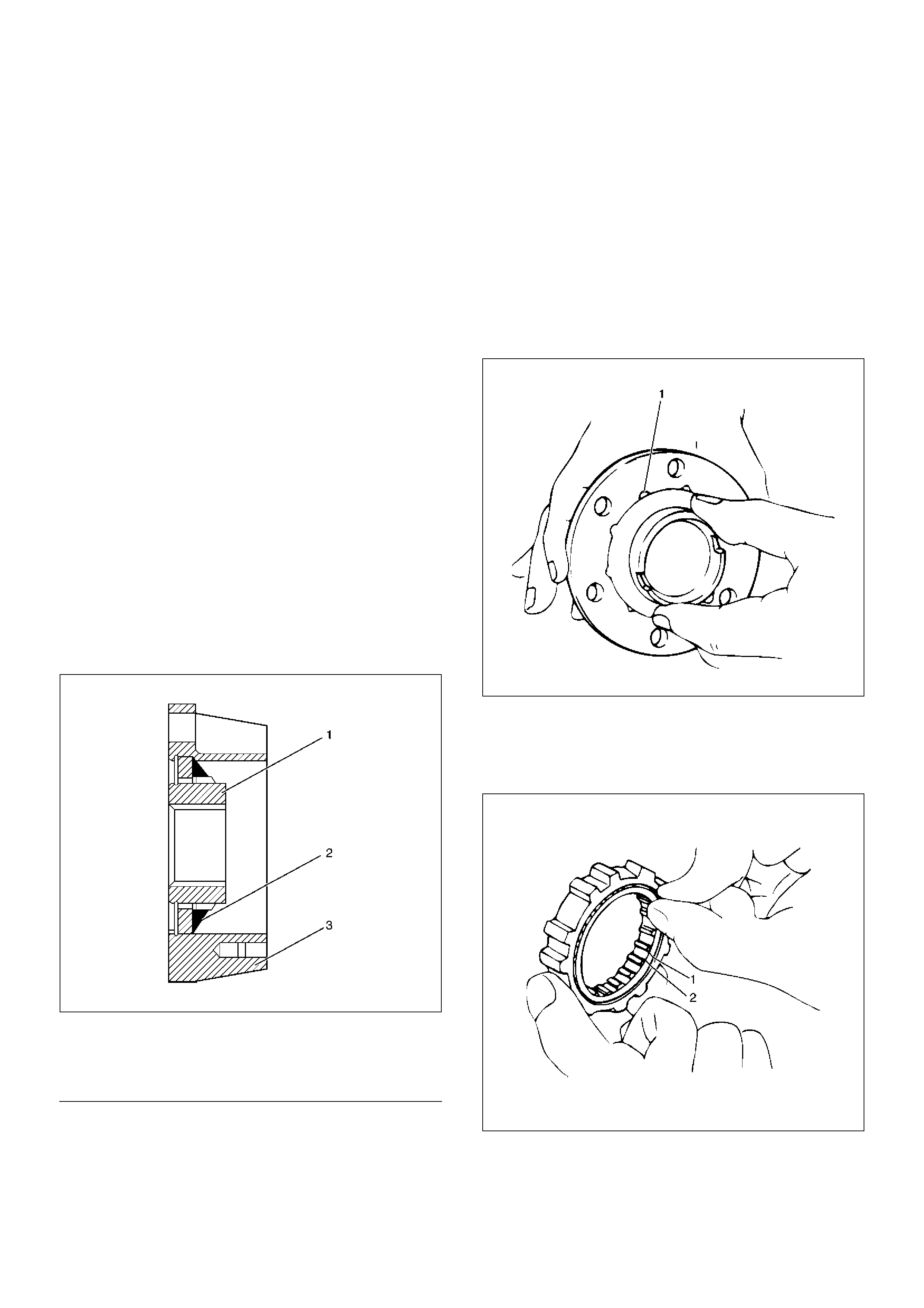
3. Install snap ring
Assembly with grease surplus being left unwiped up
as illustrated.
411RW013
EndOFCallout
4. Install inner assembly.
Apply grease to splined portion of body.
5. Install snap ring.
6. Install X–ring.
Apply wheel bearing grease to hub lock ring and fit it
in knob paying attention to mounting direction.
NOTE: After fitting, make sure that the hub lock ring is
not twisted.
7. Apply wheel bearing grease to ball and spring and
fit them in knob.
8. Install knob.
1. Apply grease to outer circumference of knob
and inner circumference of cover.
2. Align detent ball (1) to a groove cut in the cover.
411RW014
9. Install snap ring.
Turn the smoother face to knob side.
10. Align the end of retaining spring (1) with clutch
spring groove (2) and fit in the spring.
411RW015
Legend
(1) Inner Assembly
(2) Apply Grease
(3) Body
11. Install follower to clutch so that follower nails (large)
(1) will come closer to the bent portion of retaining
spring by aligning follower stopper nail with outer
teeth of clutch. Then, fit in with follower's nails
(small) (2) caught in spring.
411RW016
12. Install compression ring.
Turn the smaller diameter side toward follower and
fit spring in clutch.
13. Align follower nail (1) to handle groove (2). and then
assemble clutch with knob by pushing and turning
clutch counterclockwise to knob.
411RW017
14. Install gasket.
Make sure that there is no breakage, etc.
15. Install outer bearing outer race by driving it into the
hub, by using installer 5–8522–2118–0 and grip 5–
8840–0007–0.
411RW007
16. Install inner bearing outer race by driving it into the
hub, by using installer 5–8840–2119–0 and grip 5–
8840–0007–0.
411RW006

17. Install oil seal by using installer 5–8840–2120–0
and grip 5–8840–0007–0.
Apply grease (NLGI No.2 or equivalent) to the lip
portion.
411RW008
18. Install ABS sensor ring (if so equipped).
Tighten the bolts to the specified torque.
Torque:18N·m (1.8 kg·m/13 lbft)
19. Install hub and disc assembly.
1. Apply grease in the hub.
2. Apply wheel bearing type grease NLGI No.2 or
equivalent to the outer and inner bearing.
Grease Amount
Hub: 35 g (1.23oz)
Outer bearing: 10g (0.35oz)
Inner bearing: 15g (0.53oz)
20. Install hub nut.
1. Turn the place where there is a chamfer in the
tapped hole to the outer side, and attach the nut
by using wrench 5–8840–2117–0.
411RW005
Preload Adjustment
Tighten the hub nut to 29N·m (3.0kg·m/22lb·ft), then
fully loosen the nut.
Tighten the hub nut to the value given below, using a
spring scale on the wheel pin.
Bearing Preload
New bearing and New oil seal:
20-25N (2-2.5kg/4.4-5.5lb)
Used bearing and New oil seal:
12-18N (1.2-1.8kg/2.6-4.0lb)
If the measured bearing preload is outside the
specifications, adjust it by loosening or tightening the
bearing nut.
411RS011
21. Install lock washer and lock screw in the following
manner.
• Turn the side with larger diameter of the tapered
bore to the vehicle outer side, and attach the
washer.
• If the bolt holes in the lock plate are not aligned
with the corresponding holes in the nut, reverse
the lock plate.
• If the bolt holes are still out of alignment, trun in
the nut just enough to obtain alignment.
• Screw is to be fastened tightly so its head may
come lower than the surface of the washer.
411RS012
22. Install body assembly.
• Apply adhesive (LOCTITE 515 or equivalent) to
both joining faces.
• Tighten the bolts to the specified torque.
Torque:59N·m (6.0 kg·m/43 lbft)
23. Install snap ring and shim.
Adjust the clearance between the free wheeling hub
body and the snap ring.
Clearance:
0-0.3mm (0-0.012in)
Shims Available:
0.2mm, 0.3mm, 0.5mm, 1.0mm, (0.008in, 0.012in,
0.020in, 0.039in)
411RW002
24. Install cover assembly.
Align stopper nails (1) to grooves of body (2).
411RW019
25. Tighten the cover bolts to the specified torque.
Torque:12N·m (1.2 kg·m/104lbin)
Main Data and Specifications
Torque Specifications
E04RW022
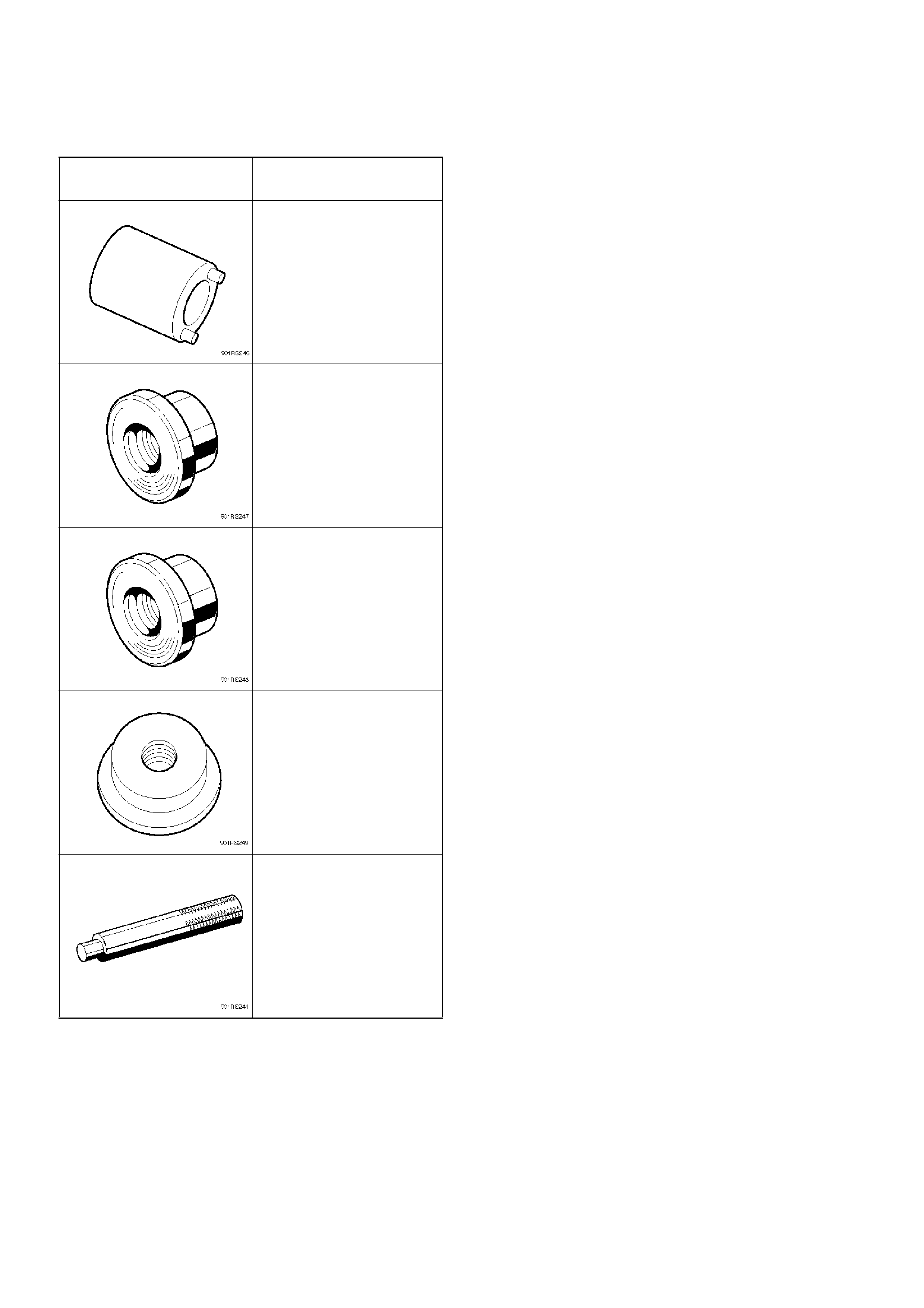
Special Tools
ILLUSTRATION TOOL NO.
TOOL NAME
5–8840–2117–0
(J–36827)
Wrench; Hub nut
5–8840–2119–0
(J–36829)
Installer; Inner bearing
5–8840–2118–0
(J–36828)
Installer; Outer bearing
5–8840–2120–0
(J–36830)
Installer; Oil seal
5–8840–0007–0
(J–8092)
Grip
Front Drive Shaft Joint
Front Drive Shaft Joints Replacement
•Refer to Front Drive Axle Assembly Replacement in
this section, and refer to Front Hub and Disc in
Suspension section.
Front Hub Bearing Preload Check
Check the hub bearing preload at the wheel pin.
New bearing and New oil seal
Preload: 20 – 25N (2.0 – 2.5 kg/4.4–5.5 lb)
New bearing and New oil seal
Preload: 12 –18N (1.2 – 1.8kg/2.6–4.0 lb)
411RS001
Inspection Of Shift On The Fly System Gear
Oil
412RT002
1. Open filler plug and make sure that the oil is up to
the plug port.
If the level oil is low, replenish with gear oil GL–5
grade.
2. Tighten the filler plug to specified torque.
Torque:7.8N·m (7.9kg·cm/58lbin)
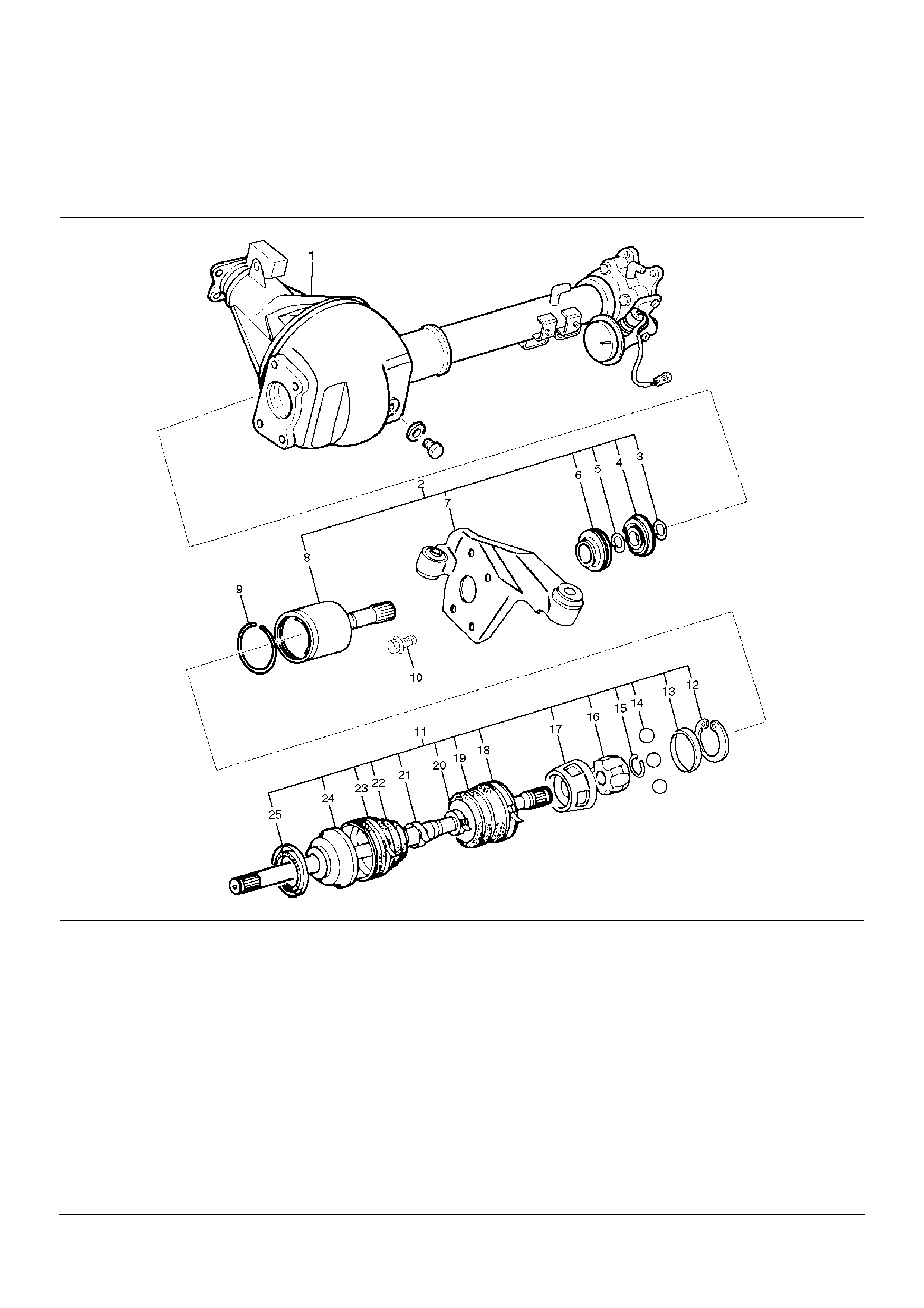
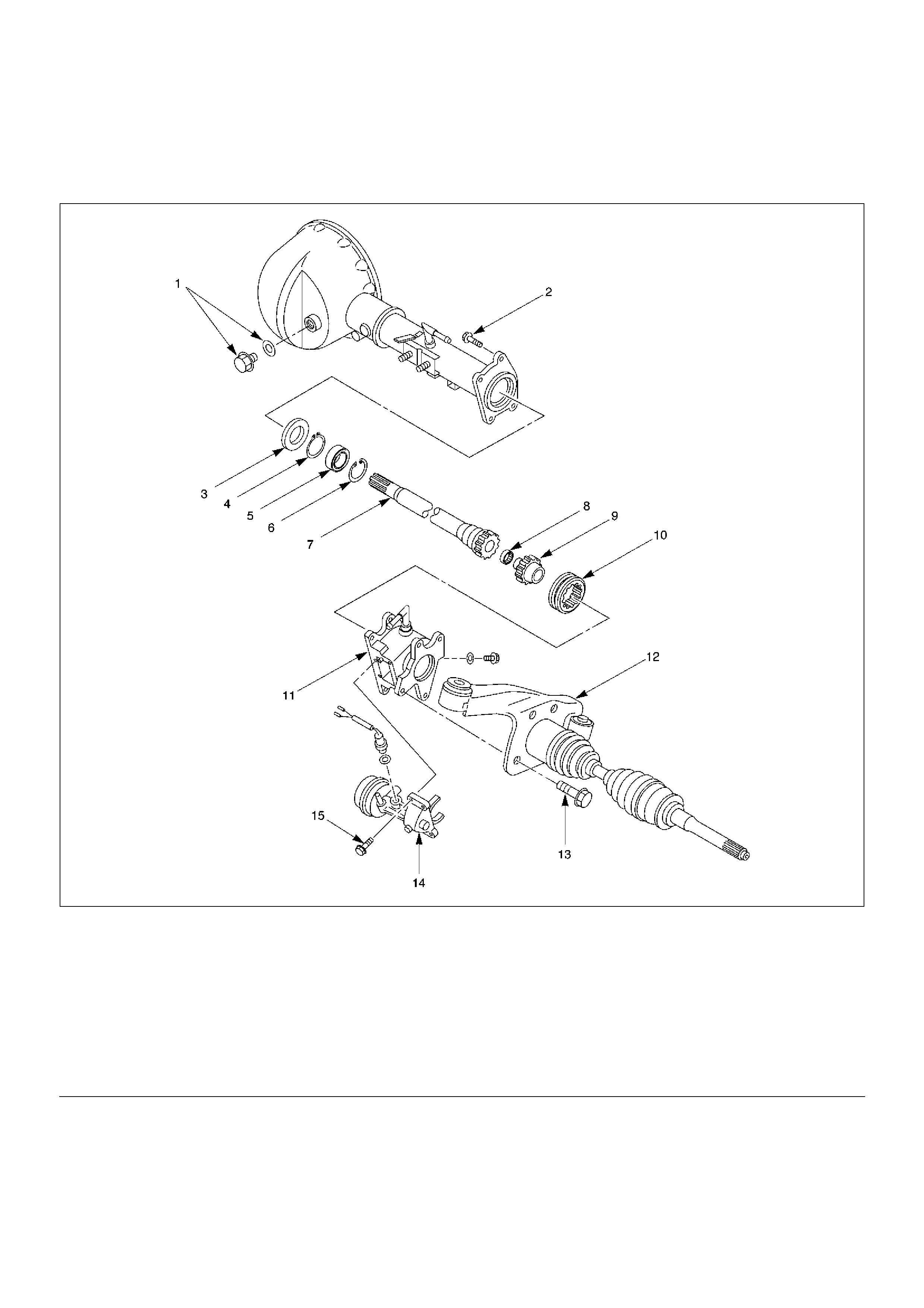
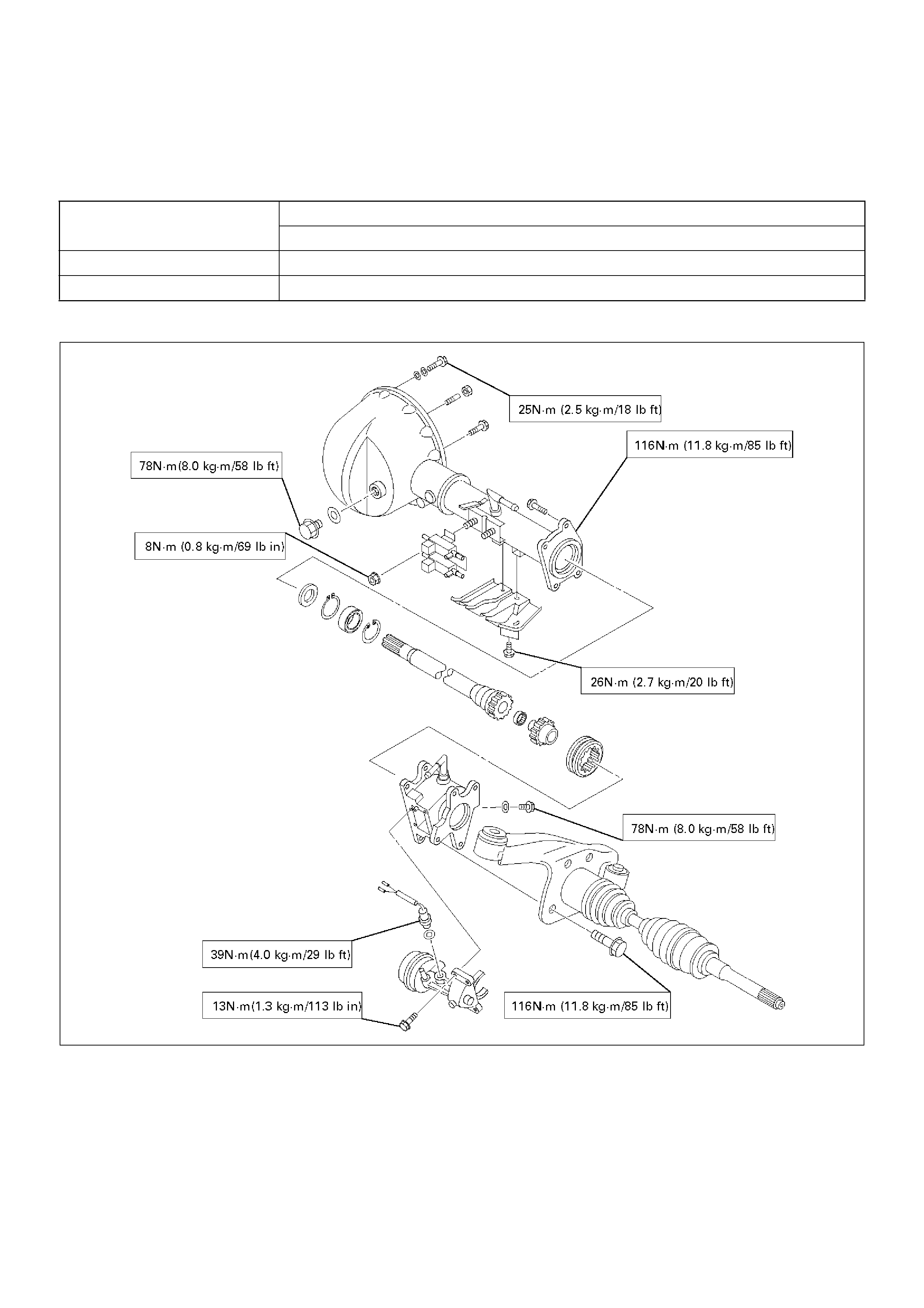
Front Axle Drive Shaft
Front Axle Drive Shaft and Associated Parts
This illustration is based on the model equipped with shift on the fly system.
412RW003
EndOFCallout
Leg
end
(1) Axle Case and Differential
(2) DOJ Case Assembly
(3) Snap Ring
(4) Bearing
(5) Snap Ring
(6) Oil Seal
(7) Bracket
(8) DOJ Case
(9) Circlip
(10) Bolt
(11) Drive Shaft Joint Assembly
(12) Snap Ring
(13) Spacer
(14) Ball
(15) Snap Ring
(16) Ball Retainer
(17) Ball Guide
(18) Band
(19) Bellows
(20) Band
(21) Band
(22) Bellows
(23) Band
(24) BJ Shaft
(25) Dust Seal
Disassembly
NOTE: For the left side, follow the same steps as right
side.
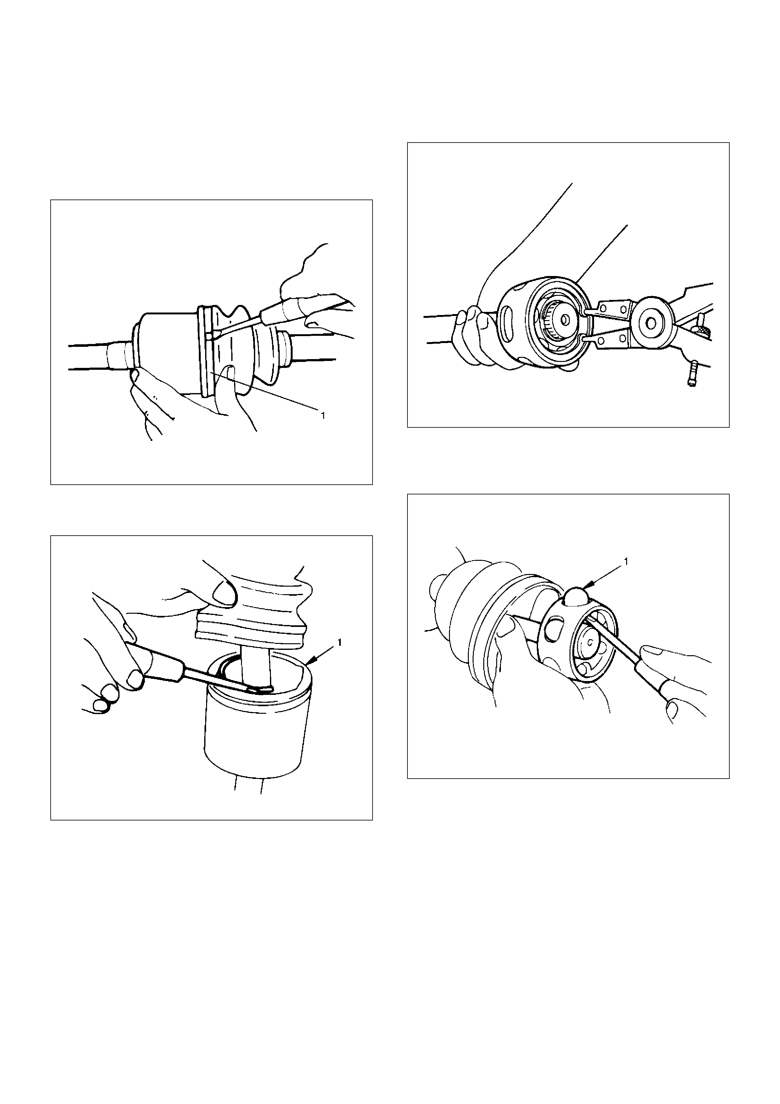
1. Raise the hooked end of the band (1) with a
screwdriver or equivalent.
412RS009
2. Remove band.
3. Pry off circlip (1) with a screwdriver or equivalent.
412RS010
4. Remove drive shaft joint assembly.
5. Using snap ring pliers, remove the snap ring.
412RS011
6. Remove spacer.
7. Remove the six balls (1) with a screwdriver or
equivalent.
412RS012

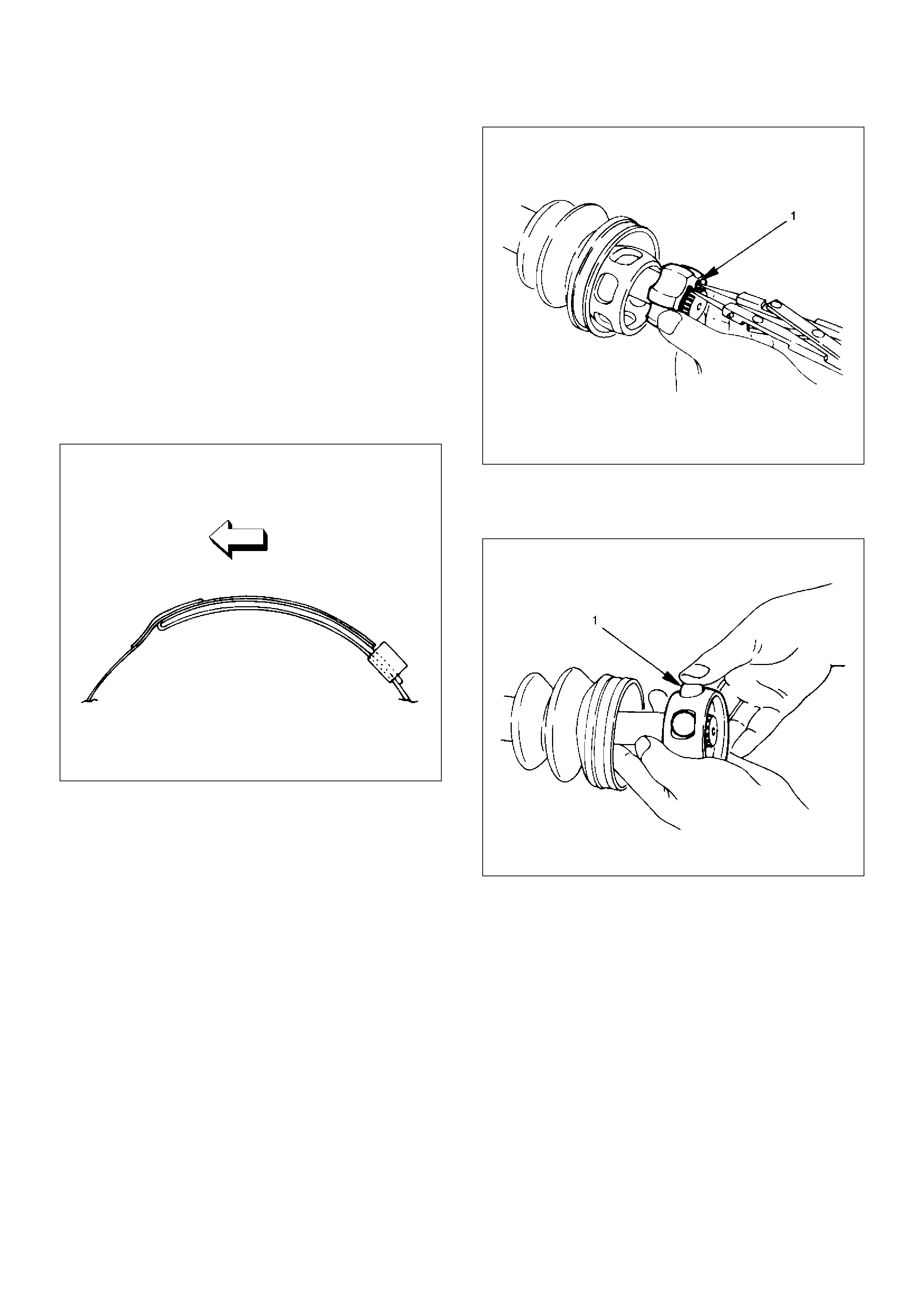
8. Using snap ring pliers, remove the snap ring (1)
fastening the ball retainer to the center shaft.
412RS013
9. Remove ball retainer, ball guide and bellows.
10. Raise the hooked end of the band (1) with a
screwdriver or equivalent.
412RS014
11. Remove band.
12. Remove bellows.
13. Remove dust seal.
14. Remove BJ shaft assembly.
15. Remove the mounting bracket fixing bolts, and then
remove DOJ case assembly from the axle ca se.
16. Remove snap ring and bearing.
17. Remove snap ring and oil seal.
18. Remove bracket.
Inspection and Repair
Make necessary correction or parts replacement if wear,
damage, corrosion or any other abnormal conditions are
found through inspection.
Check the following parts:
1. Drive shaft joint assembly
2. DOJ case, ball, ball guide, ball retainer
3. Bellows
4. Bearing
5. Dust seal, oil seal
Bushing Replacement
• Remove the bushings using a remover 5–8840–
2309–0 and hammer.
412RW051
• By using installer and base 5–8840–2309–0, press
fit the bushings into the bracket.
412RW052
Reassembly
1. Install DOJ case to bracket.
2. Install oil seal and fix snap ring.
3. Install bearing and fix snap ring.
4. Install bracket to axle case. Tighten the bracket bolt
to the specified torque.
Torque:116N·m (11.8kg·m/85lbft)
5. Apply 150g of the specified grease in BJ .
6. Install dust seal .
7. Apply a thin coat of grease to the shaft for smooth
installation then install bellows.
8. Install band. Note the setting direction. After
installation, check that the bellows is free from
distortion.
412RS017
9. Install another bellows and fix band.
10. Install the ball guide with the smaller diameter side
ahead onto the shaft.
11. Install ball retainer.
12. Using snap ring pliers, install the snap ring (1)
securing the ball retainer to the shaft.
412RS013
13. Align the track on the ball (1) retainer with the
window in the cage, and install the six balls into
position.
412RS018
14. Install spacer.
15. Install snap ring.
16. Enclose 150g of the specified grease in DOJ case,
then install drive shaft joint assembly. After
reassembly, move the DOJ longitudinally several
times to get to fit.
17. Install the circlip (1) so that open ends are
positioned away from the ball groove.
412RS019
412RS020
EndOFCallout
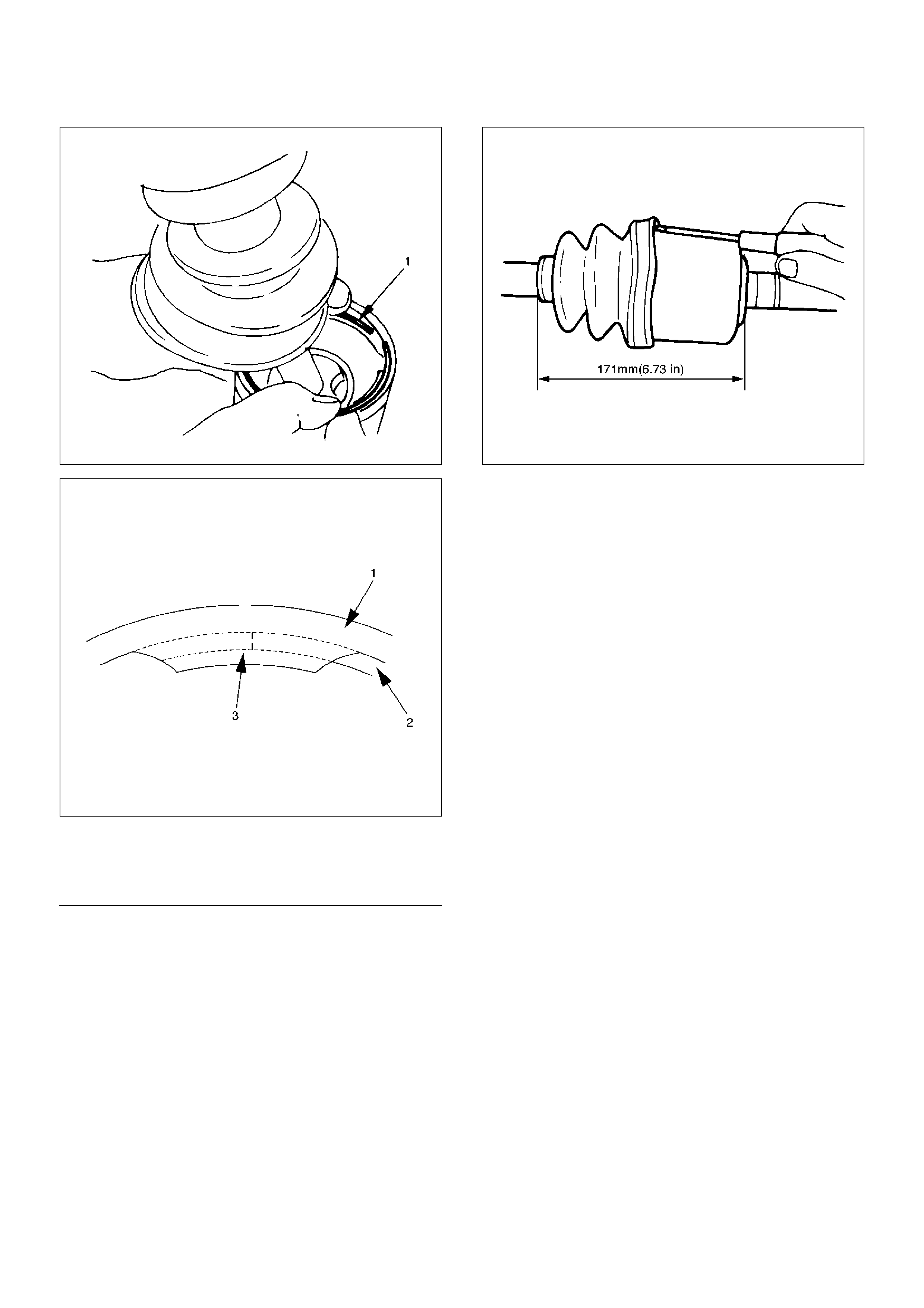
18. Install bellows. Adjust the air pressure within the
bellows by inserting a screwdriver or equivalent, so
that it equals atmospheric pressure.
412RW053
19. Install Band. After installation, check that the
bellows is free from distortion.
Legend
(1) Outer Case
(2) Circlip
(3) Open Ends
Shift On The Fly System
Shift On The Fly System and Associated Parts
412RW004
EndOFCallout
Disassembly
1. Remove filler plug and gasket, drain oil.
2. Loosen mounting bracket fitting bolts and remove
front axle drive shaft from front axle case.
3. Remove Actuator Assembly and draw out actuator
ASM.
4. Remove housing.
5. Remove sleeve.
6. Remove clutch gear.
Leg
end
(1) Filler Plug
(2) Bolt
(3) Oil Seal
(4) Snap Ring(External)
(5) Inner Shaft Bearing
(6) Snap Ring(Internal)
(7) Inner Shaft
(8) Needle Bearing
(9) Clutch Gear
(10) Sleeve
(11) Housing
(12) Front Axle Drive Shaft (LH side) with Bracket
(13) Bolt
(14) Actuator Assembly
(15) Bolt
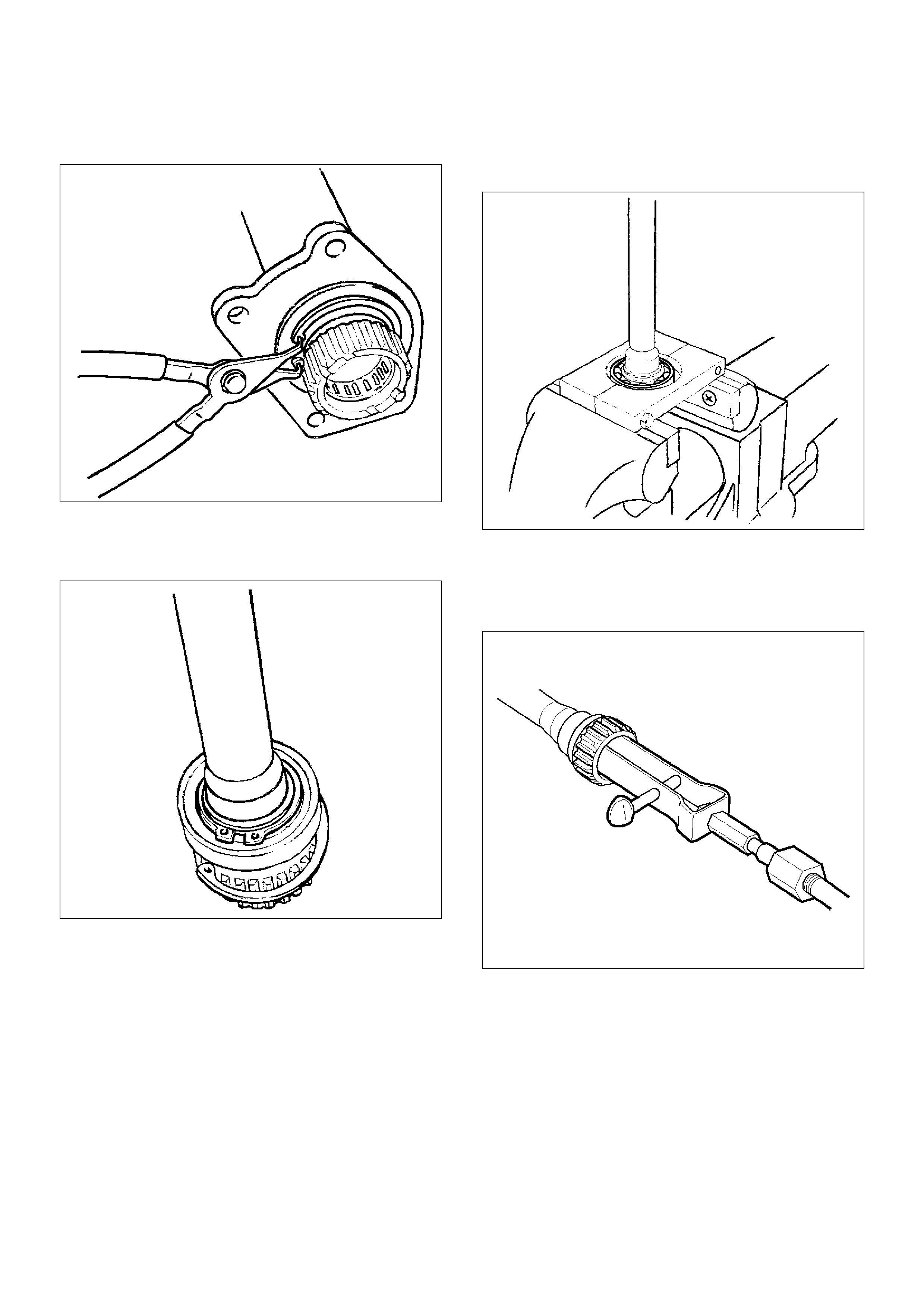
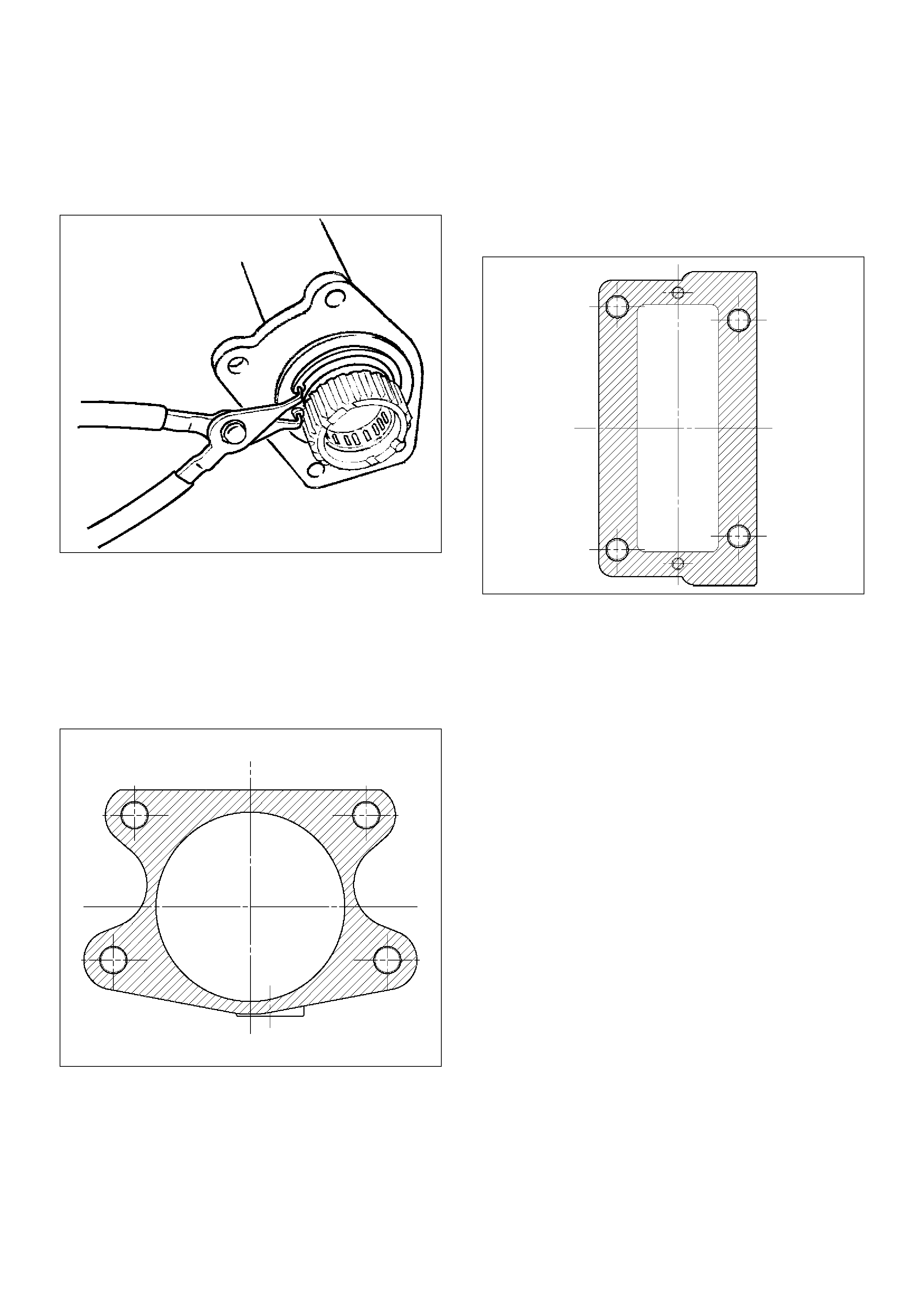
7. Remove snap ring from front axle case by using
snap ring pliers.
412RW017
8. Take out inner shaft from front axle case.
9. Remove snap ring from inner shaft by using snap
ring pliers.
412RW016
10. Remove inner shaft bearing by using a remover 5–
8840–2197–0 and press.
NOTE: Be careful not to damage the shaft.
412RW015
11. Remove needle bearing from inner shaft by using a
remover 5–8840–0027–0 and sliding hammer 5–
8840–0084–0.
NOTE: Be careful not to damage the shaft.
412RS045
12. Remove oil seal from front axle case.
NOTE: Be careful not to damage the front axle case.
Inspection and Repair
Inspect the removed parts. If there are abnormalities
such as wear and damage, take corrective action or
replace.
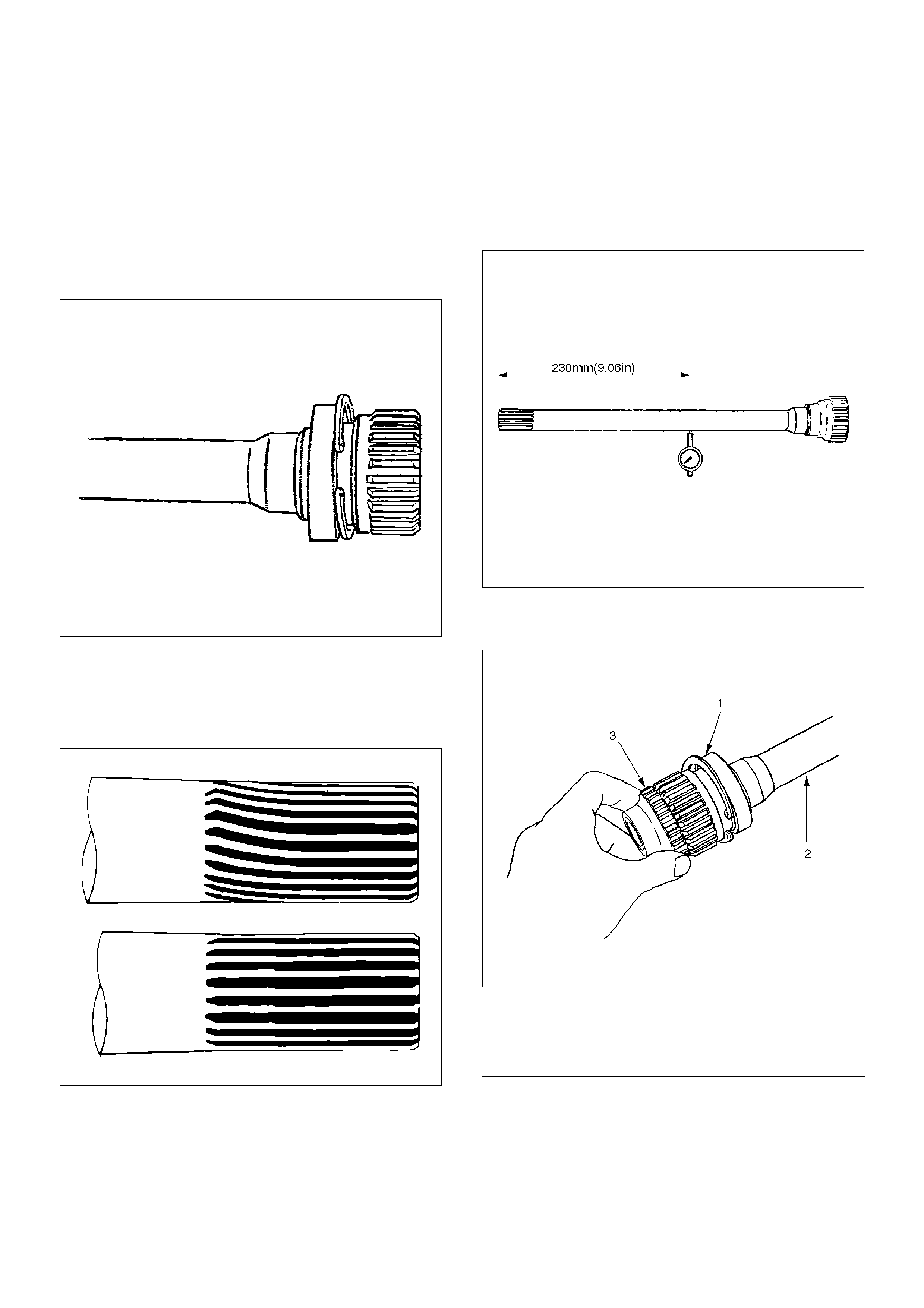
Visual Check
1. Check and see if the inner shaft has any
abnormalities such as wear and damage.
412RW014
2. When inspecting the inner shaft, be sure to check
and see if its splined part is twisted, worn, or
cracked. If so, replace with a new shaft. In case of
an abnormality in its gear part (a slide with sleeve),
replace the shaft.
420RS008
Inner Shaft Run–Out
With both end centers supported, rotate the shaft slowly
and measure deflection with a dial gauge.
Limit:0.5mm (0.02in) max.
NOTE: Do not heat the shaft to correct its bend.
412RS026
Inner Shaft Bearing
412RW006
EndOFCallout
1. Inspect the state of inner shaft bearing. If any
abnormality such as roughness is found, replace
with a new inner shaft bearing.
2. Insert a clutch gear and check the state of needle
bearing.
3. If there is an abnormality such as roughness,
replace the needle bearing.
Legend
(1) Inner Shaft Bearing
(2) Inner Shaft
(3) Clutch Gear
Sleeve Condition
Check and see that there is no wear, damage, or
cracking in the sleeve.
NOTE: Close inspection of the groove and inner gear
are required because those are important parts.
Sleeve Function
412RW011
Operate the sleeve with the inner shaft combined with
the clutch gear. If roughness is felt, replace the sleeve.
NOTE: Gear oil should be applied to the contact
surface of gear.
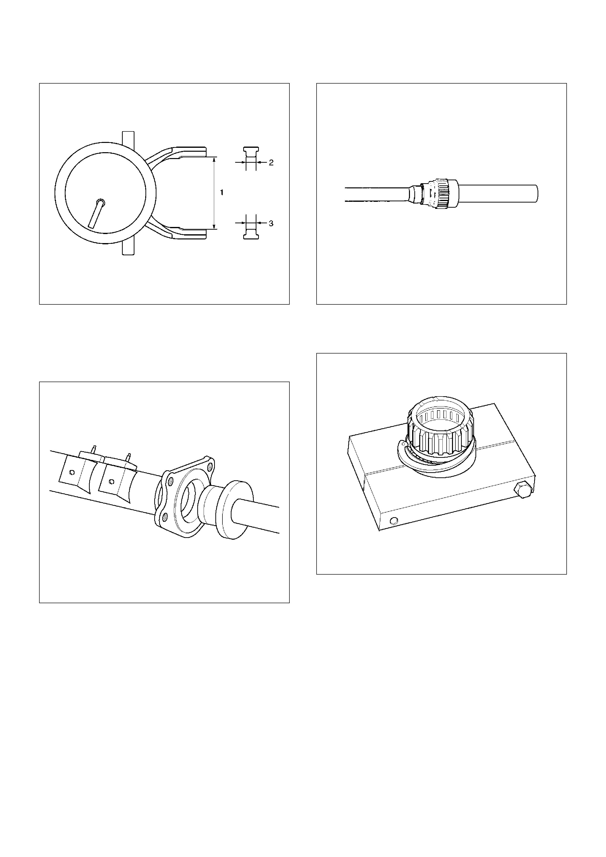
Check the width of sleeve center groove.
Limit:7.1mm (0.28in) max.
412RW022
Clutch Gear Condition
Check and see that there is no wear, damage, cracking,
or any other abnormality in the clutch gear.
Clutch Gear Function
412RW010
If there is an abnormality such as roughness when
operated in combination with sleeve, replace the clutch
gear.
NOTE: When inspecting, gear oil should be applied to
the contact surface of gear.
Clutch Gear Journal Diameter
Make sure of the size illustrated.
Limit:36.98mm (1.456 in) min.
412RW009
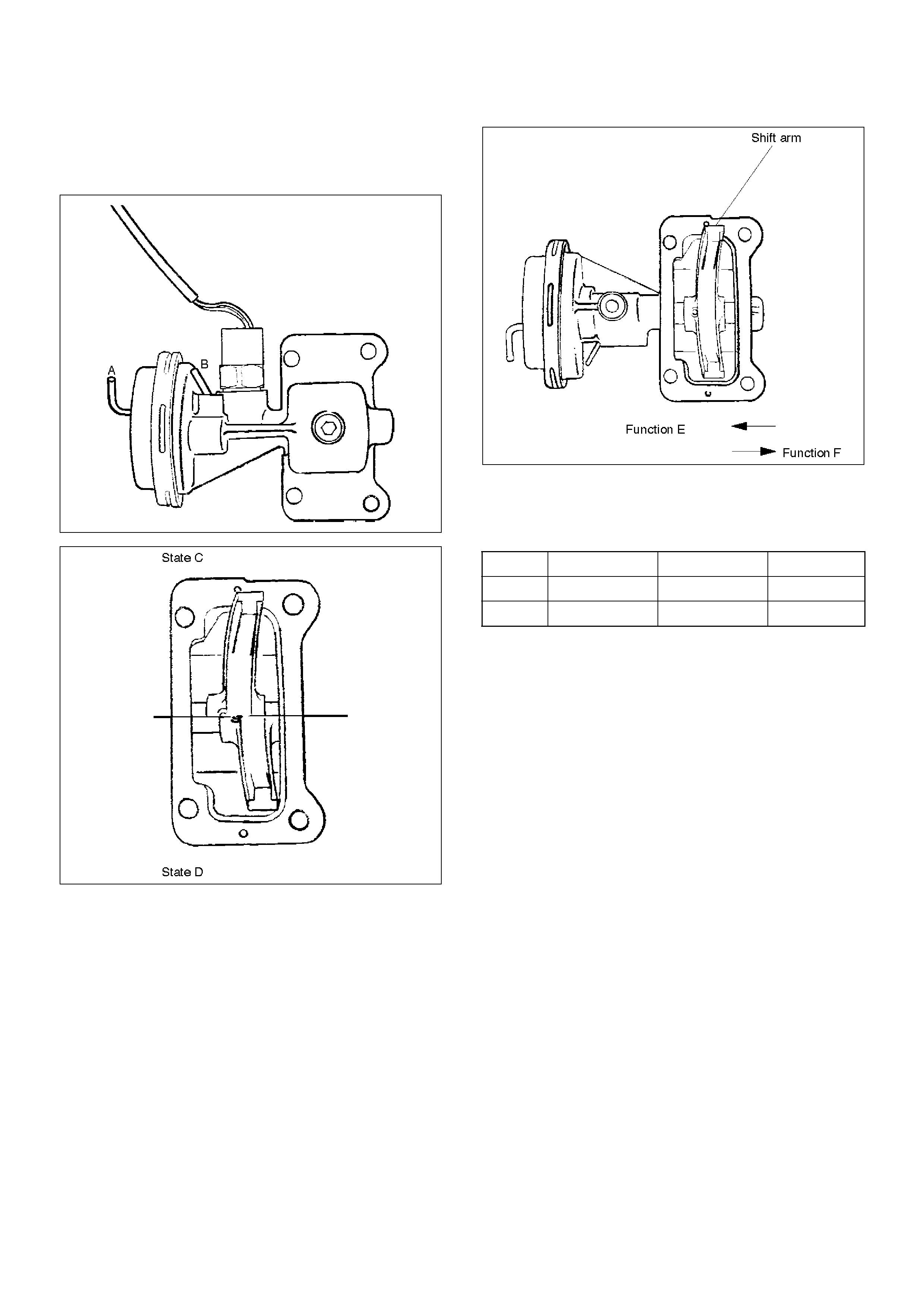
Actuator
Check and see that there is no damage, cracking, or
other abnormality.
Functional Check
412RW021
412RW013
412RW007
Disconnect the shift position switch and make sure of
function with a vacuum of –400 mmHg applied to Ports
A and B, in accordance with the table below.
If there is an abnormality, replace the actuator as an
assembly.
NOTE:
1. If the actuator works under –400mmHg or less,
there is no functional problem.
2. Be careful not to permit the entry of water or dust
into the ports of the actuator.
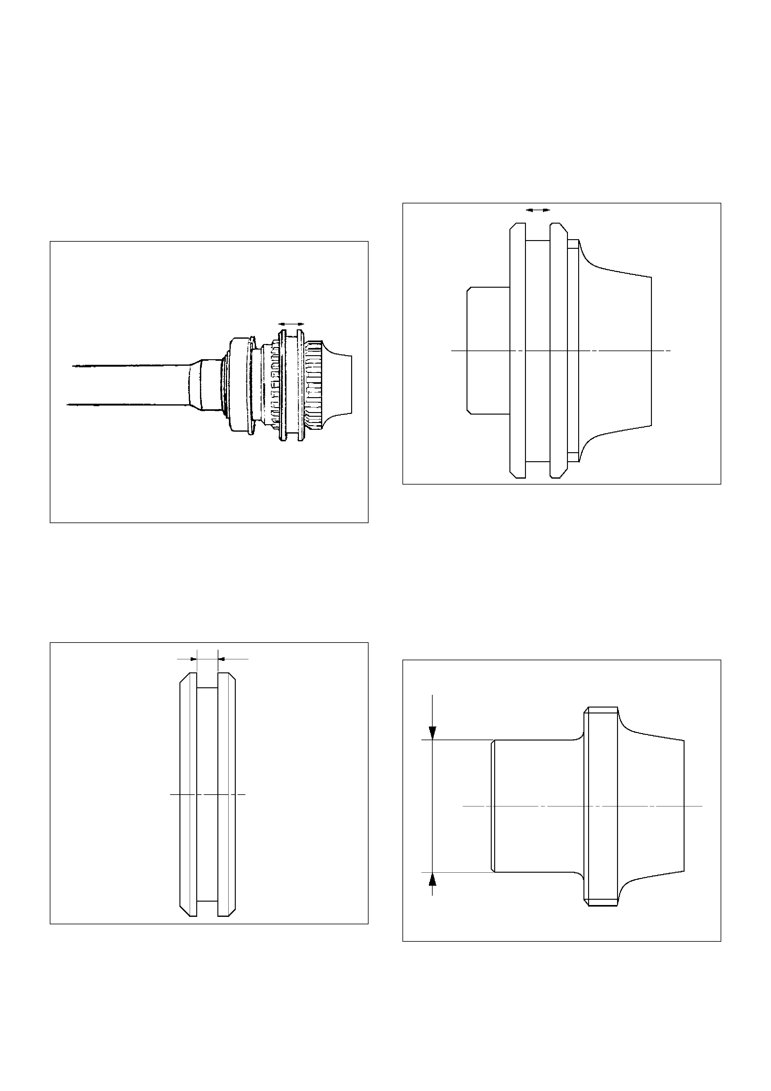
Dimensional Check
Measure illustrated sizes 1, 2, and 3.
Limit
1=64.3mm (2.53in) max.
2=6.7mm (0.26in) min.
3=6.7mm (0.26in) min.
State Port A Port B Function
C –400 mmHg A/P E
D A/P –400 mmHg F
412RS037
Reassembly
1. Install the new oil seal which has been immersed in
differential gear oil, by using an oil seal installer 5–
8840–2407–0 and grip 5–8840–0007–0.
412RS043
2. Force a new needle bearing into inner shaft by
using a installer 5–8840–2408–0 and grip 5–8840–
0007–0.
412RS051
3. Place a new snap ring(internal) in inner shaft.
Force a new inner shaft bearing into the inner shaft
by using a installer 5–8840–2197–0 and press.
412RS044
4. Install snap ring(external).
NOTE: Be careful not to damage the inner shaft.
5. Clean the housing contact surface of the front axle
case and insert inner shaft assembly into the front
axle case.
NOTE: Be careful not to damage seal.
6. Install snap ring (internal) in the groove of front axle
case.
NOTE: Be sure to install the snap ring properly.
412RW017
7. Apply differential gear oil to clutch gear, then install
clutch gear.
8. Apply differential gear oil to sleeve, then install
sleeve.
9. Clean contact surface with the front axle and
actuator mounting surface. Apply liquid gasket to
the contact surface on the front axle case, then
install in the housing.
412RW023
10. Tighten bolts to specified torque.
Torque:116N·m (11.8kg·m/85lbft)
11. Clean the actuator contact surface with the housing
then Install and tighten shift position switch to
specified torque.
Torque:39N·m (4.0kg·m/29lbft)
12. Apply liquid gasket to the contact surface on the
actuator side.
412RW012
13. Align shift arm with the groove of sleeve and install
the actuator.
14. Tighten bolts to specified torque.
Torque:13N·m (1.3kg·m/113lbin)
15. Install front axle drive shaft and mounting bracket.
Tighten fitting bolts to specified torque.
Torque:116N·m (11.8kg·m/85lbft)
16. Pour specified amount of differential gear oil to filler
plug.
Front Differential
Oil Capacity: 1.4lit(1.23Imp qt/1.48US qt)
Actuator Housing
Oil Capacity: 0.12lit(0.10Imp qt/0.13US qt)
17. Install filler plug through gasket and tighten to
specified torque.
Torque:78N·m (58lbft)
Main Data and Specifications
General Specifications
Torque Specifications
E04RW020
Front drive axle oil capacity 1.4 liter (1.23Imp qt/1.48US qt)(Differential)
0.12 liter (0.10Imp qt/0.13US qt)(Actuator Housing:Shift on the fly)
Type of lubricant Refer to chart in General Information
Axle shaft type Constant velocity joint(Birfield joint type and double offset joint)
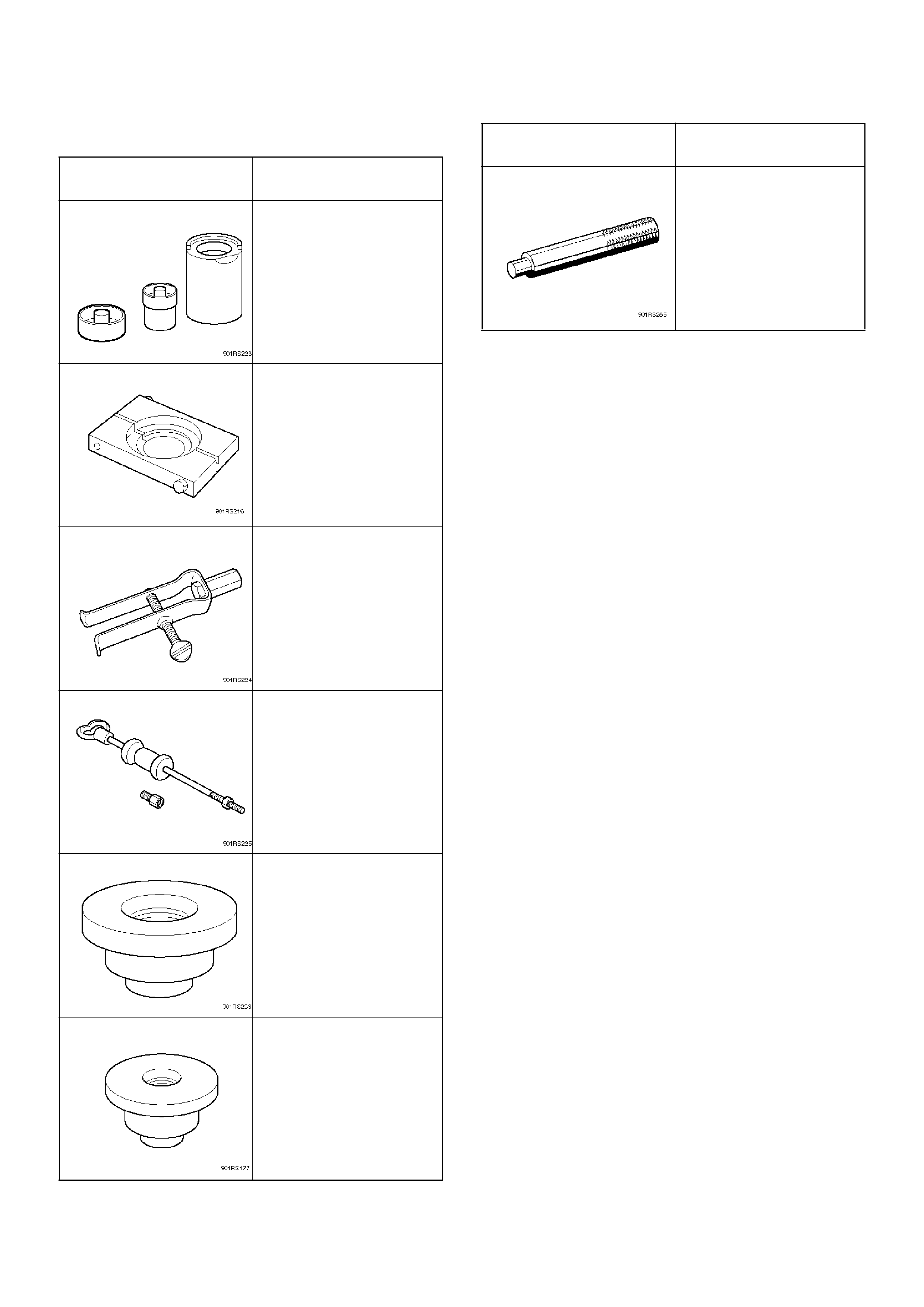
Special Tools
ILLUSTRATION TOOL NO.
TOOL NAME
5–8840–2309–0
(J–39378)
Remover and Installer;
Front Axle mount bushing
5–8840–2197–0
(J–37452)
Remover and Installer;
Inner shaft bearing
5–8840–0027–0
(J– 26941)
Remover;Bearing needle
5–8840–0084–0
(J–2619–01)
Hammer; Sliding
5–8840–2407–0
(J–41693)
Installer; Oil seal
5–8840–2408–0
(J–41694)
Installer; Bearing needle
5–8840–0007–0
(J–8092)
Grip
ILLUSTRATION TOOL NO.
TOOL NAME
Front Propeller Shaft
General Description
Since the propeller shaft is balanced carefully, welding
or any other modifications are not permitted.
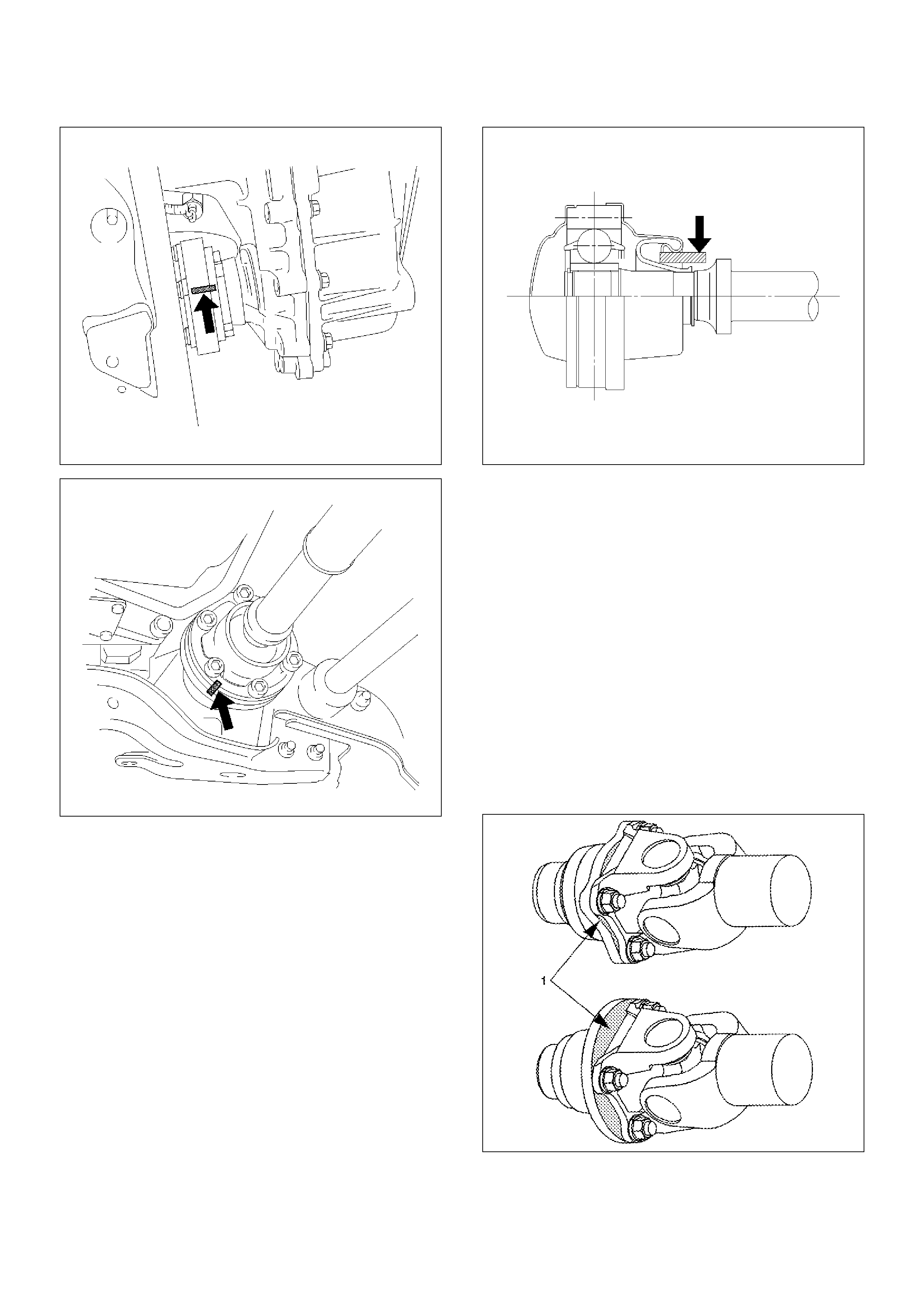
Alignment marks should be applied to each propeller
shaft before removal.
401RW002
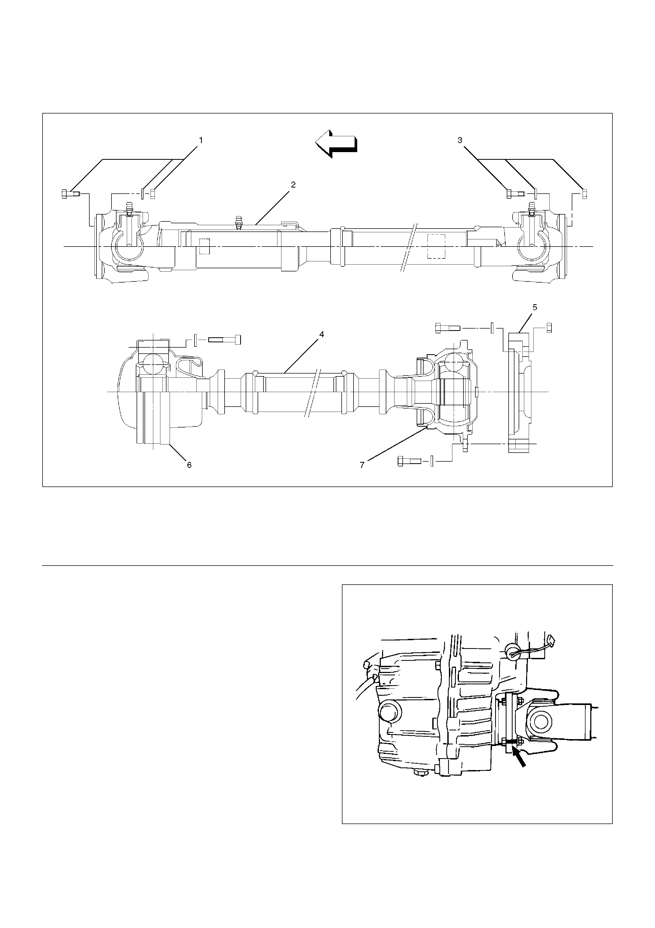
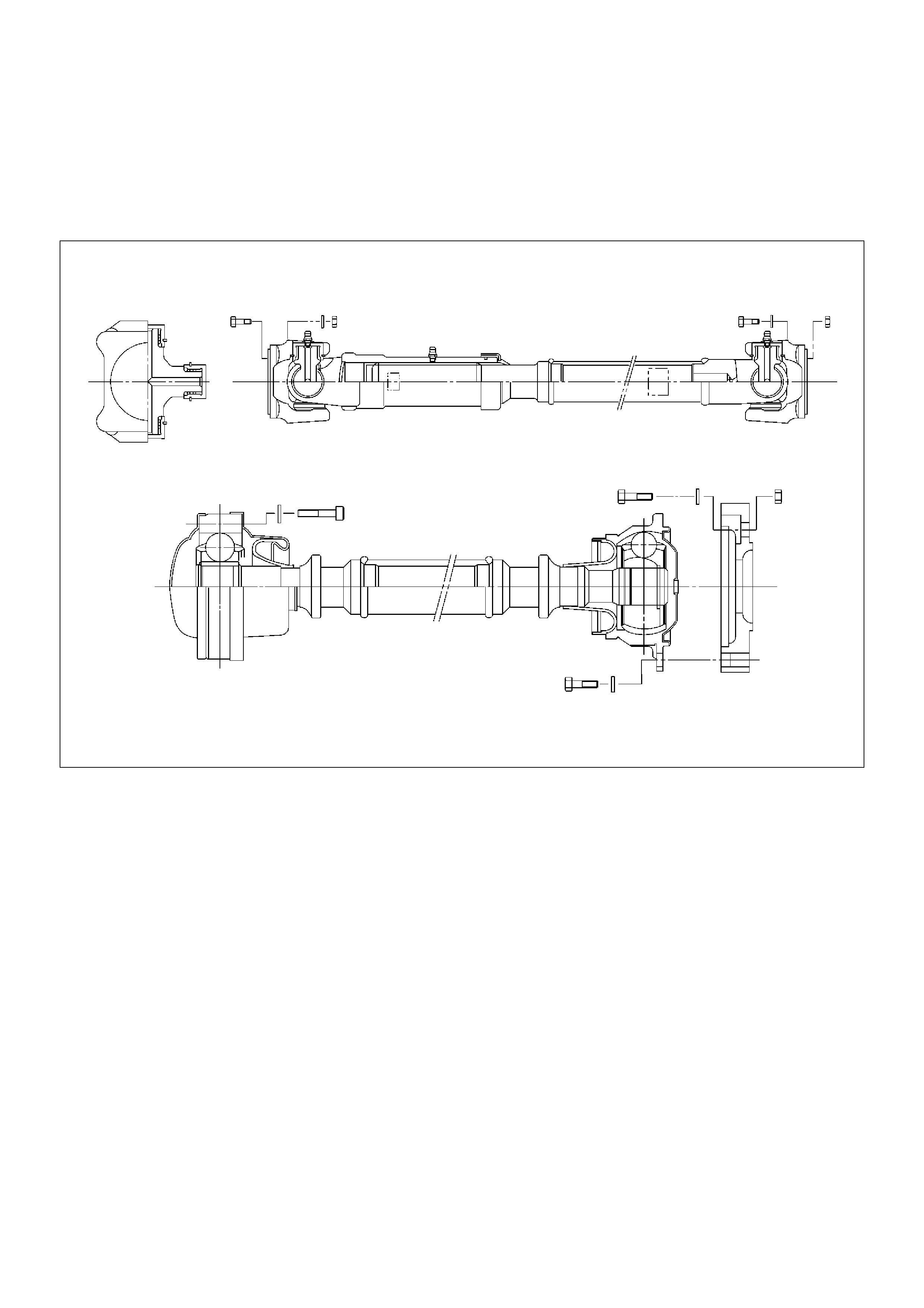
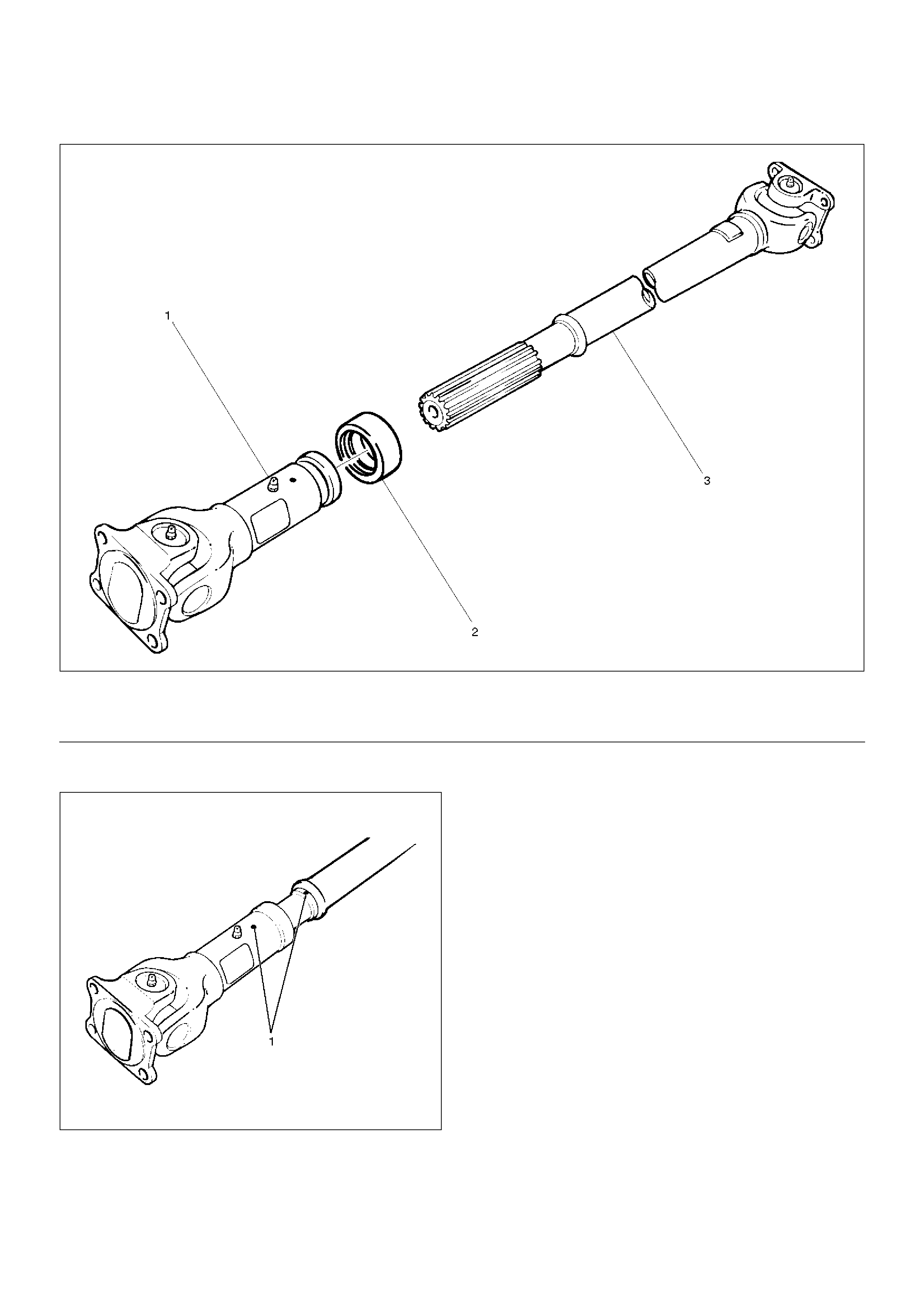
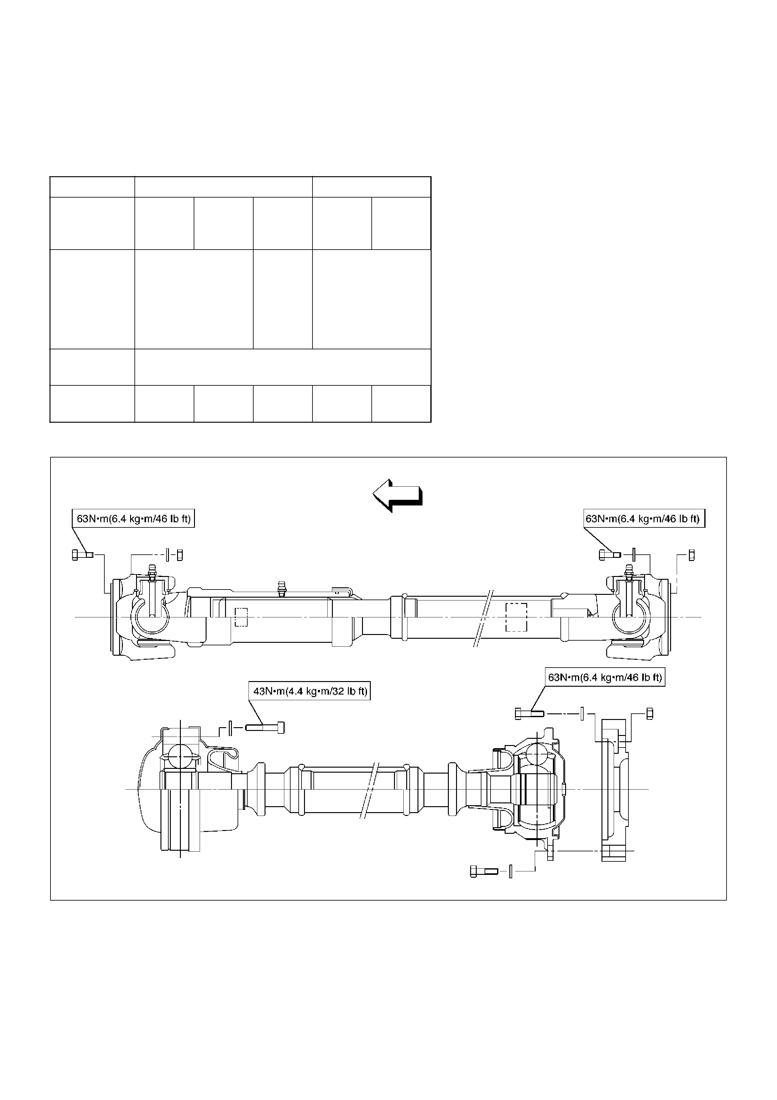
Front Propeller Shaft and Associated Parts
401RW058
EndOFCallout
Removal
1. Jack up the vehicle and support it on the chassis
stands.
2. Gear shift lever should be placed in neutral position
and parking brake released.
3. Remove the exhaust and transfer protectors.
NOTE: Apply alignment marks on the flange at the front
propeller shaft both front and rear side.
401RS020
Legend
(1) Bolt, Nut and Washer (Front Axle Side)
(2) Front Propeller Shaft
(3) Bolt, Nut and Washer (Transfer Side)
(4) Front Propeller Shaft (with TOD)
(5) Coupling
(6) LJ Constant Velocity Joint
(7) BJ Constant Velocity Joint
401RW053
401RW052
4. Remove bolt, nut and washer (Front axle side).
5. Remove bolt, nut and washer (Transfer side).
6. Remove front propeller shaft.
NOTE: If equipped with torque on demand (TOD),
when removing, installing or carring for front propeller
shaft, be sure to wind a piece of cloth round the part of
the boot with which fittings may interfere so that the
boot can be protected. The boot may be damaged if
bending force is applied to the constant velocity joint of
the shaft.
401RW051
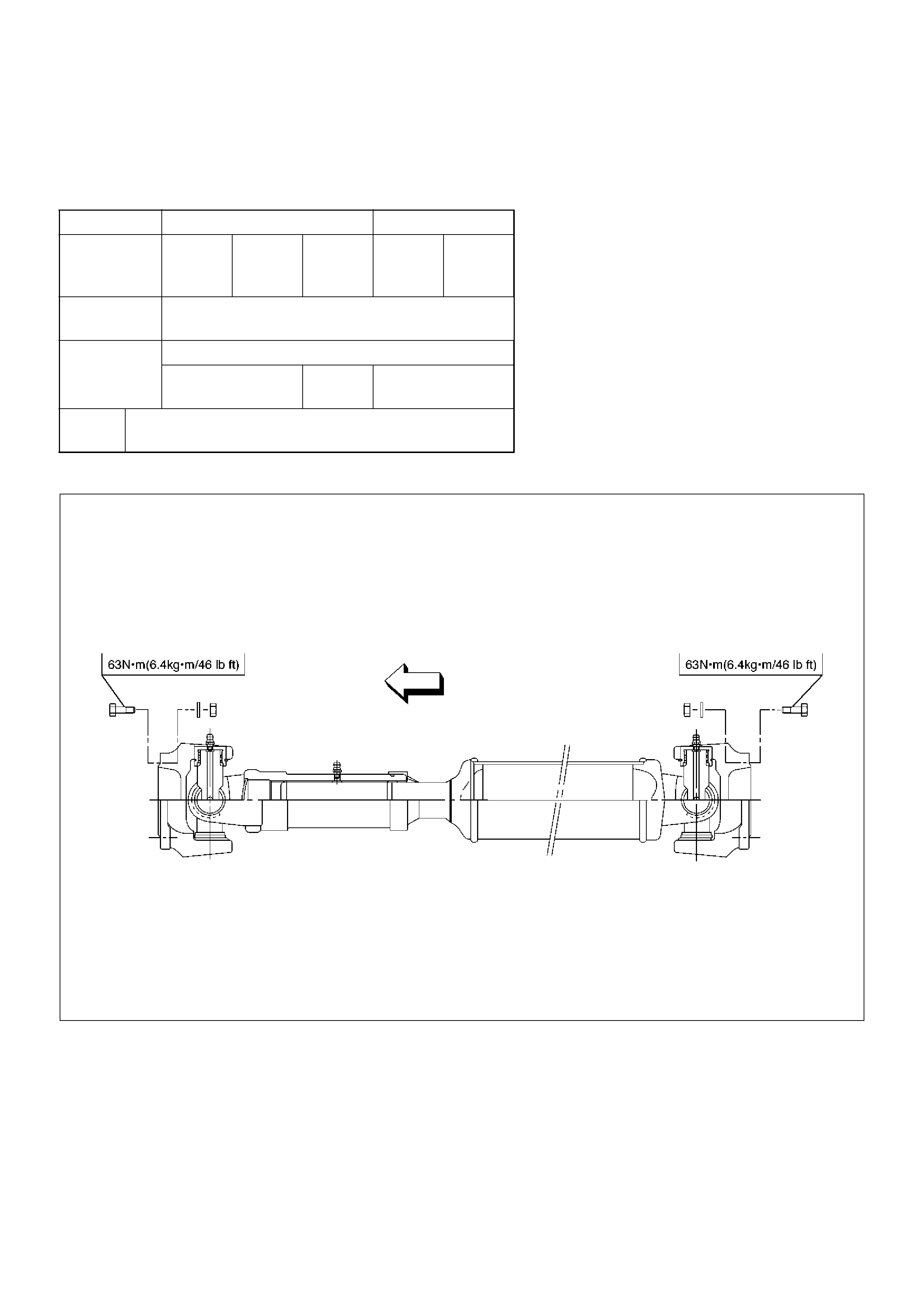
Installation
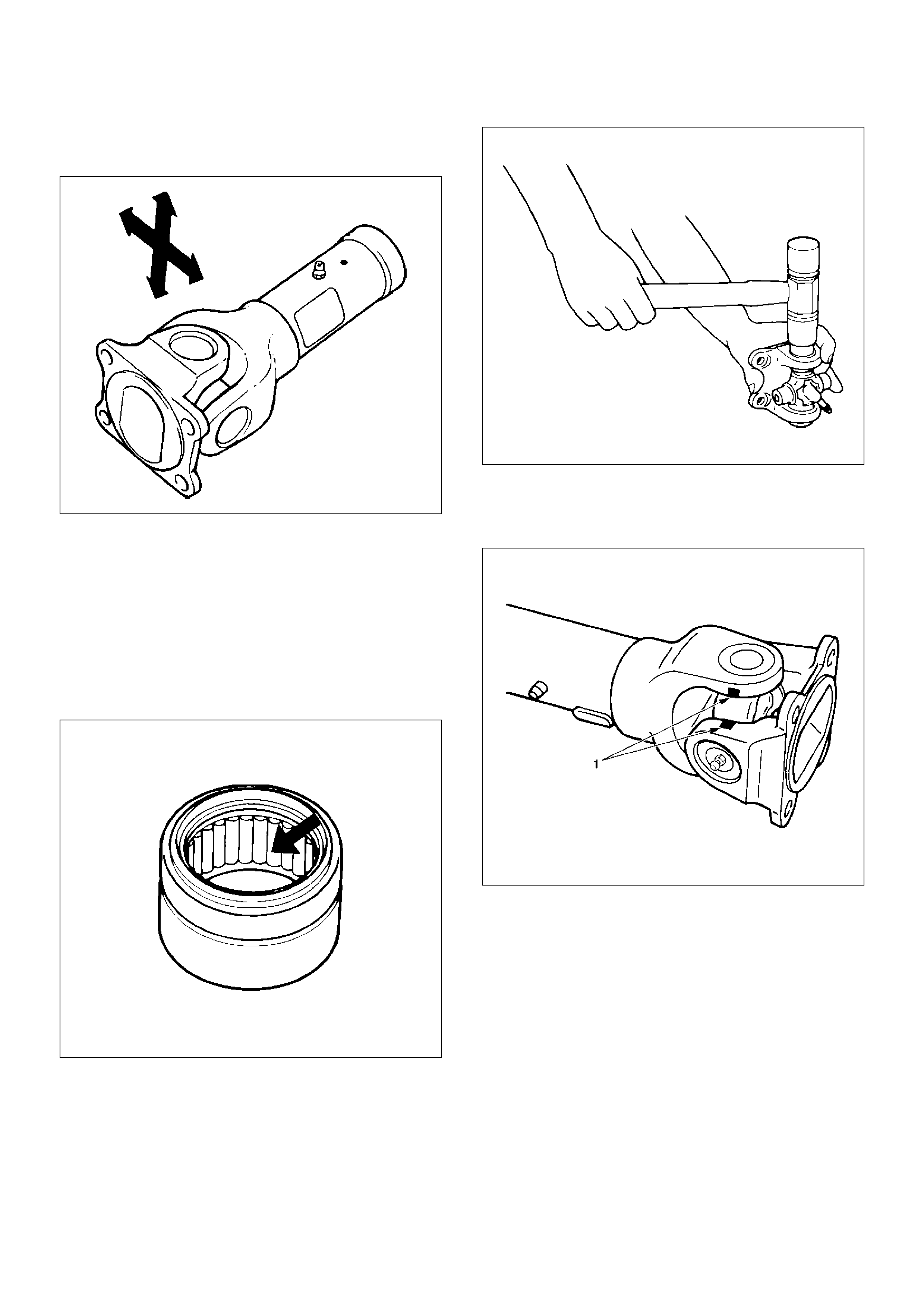
NOTE: Never install the shaft assembly backwards.
Completely remove the black paint from the connecting
surface of flange coupling on each end of propeller
shaft. Clean so that no foreign matter will be caught in
between.
1. Align the mark which was applied at removal. Install
front propeller shaft and tighten the bolts to the
specified torque.
Torque:63N·m (6.4kg·m/46 lbft)
2. Install the exhaust and transfer protectors.
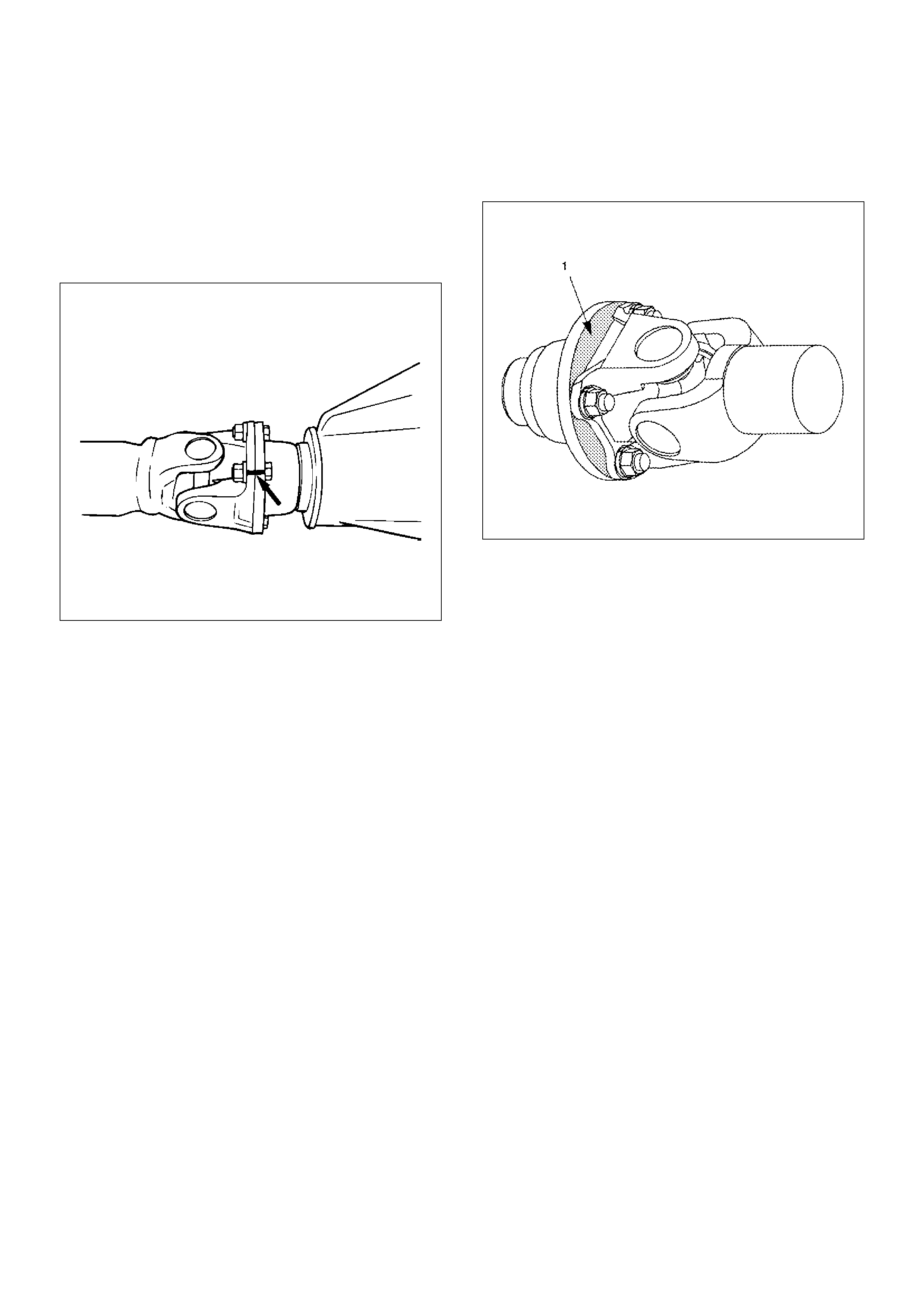
3. After installing the propeller shaft, be sure to apply
black paint (1) to exposed area (other than
connecting surface) of the entire surface of flange
coupling .
401RS019
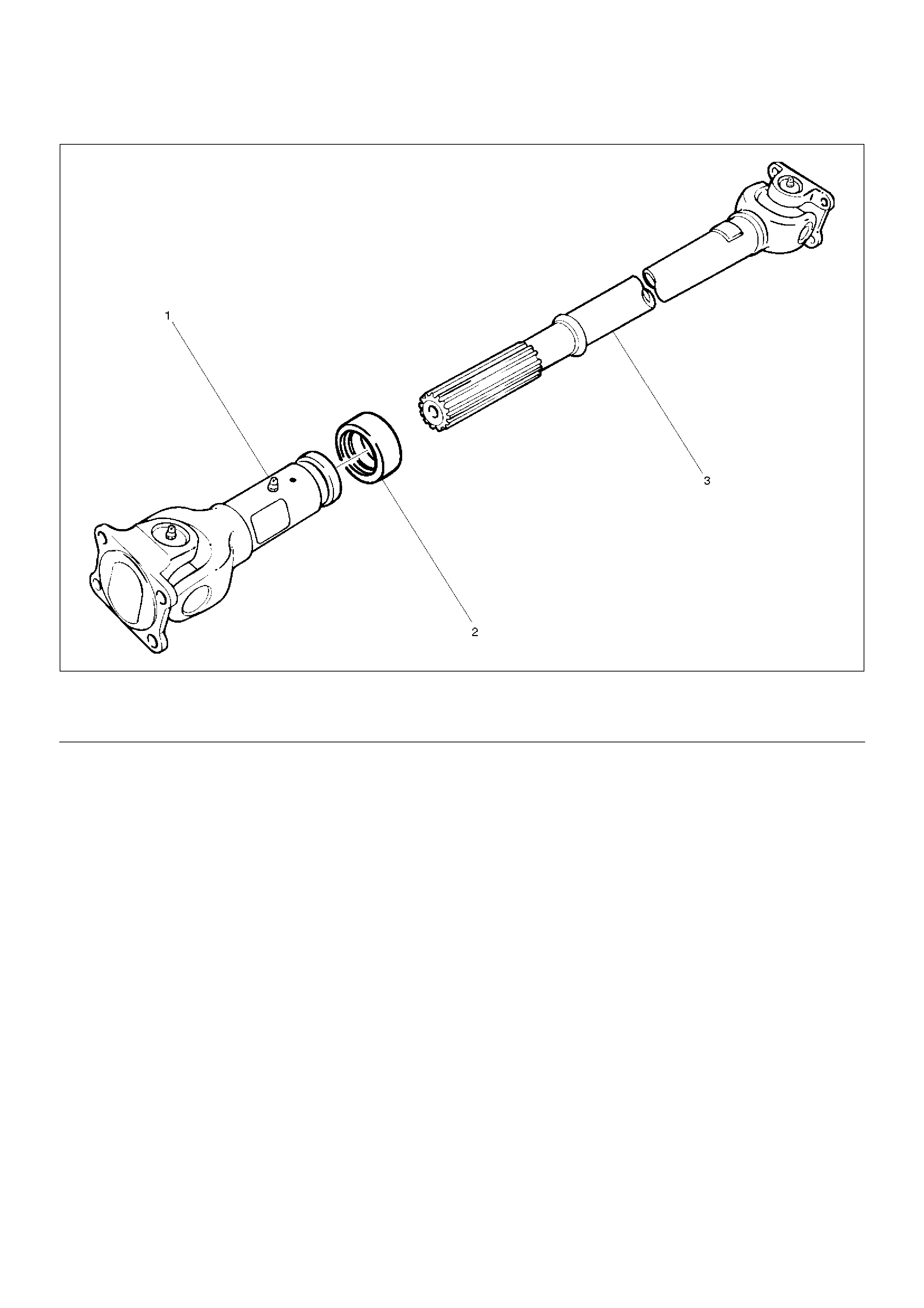
Disassembly (Except TOD 4´4)
401RW057
EndOFCallout
1. Apply alignment marks (1) on the sleeve yoke and
tube assembly then remove sleeve yoke.
401RW056
2. Remove seal.
3. Remove tube assembly.
Legend
(1) Sleeve Yoke
(2) Seal
(3) Tube Assembly
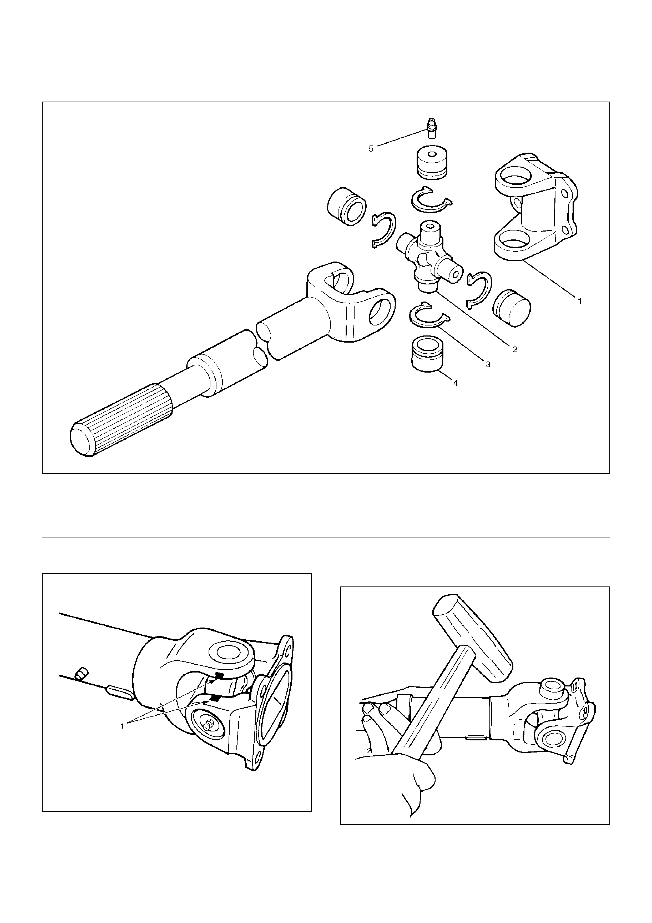
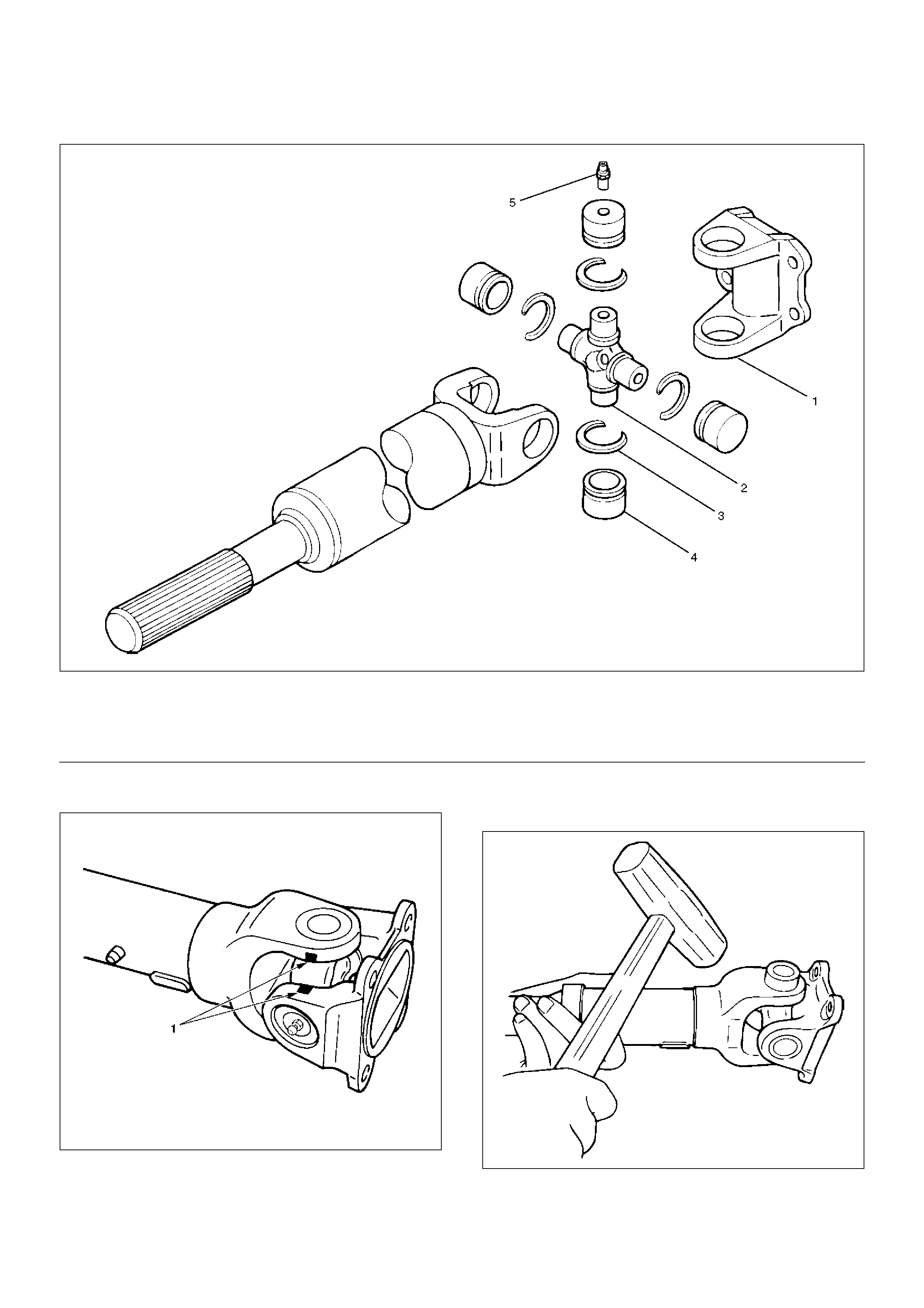
Universal Joint Disassembly
401RW055
EndOFCallout
1. Apply alignment marks (1) on the yokes of the
universal joint, then remove snap ring.
401RS028
2. Tap out the needle roller bearing by gently striking
the shoulder of the yoke, using a mallet or a copper
hammer.
401RS006
Legend
(1) Flange Yoke
(2) Spider
(3) Snap Ring
(4) Needle Roller Bearing
(5) Grease Fitting
3. Make sure of proper position for reinstallation by
applying setting marks, then remove spider .
Inspection and Repair
Make necessary correction or parts replacement if wear,
damage, corrosion or any other abnormal condition is
found through inspection.
NOTE: When any part of the journal assembly (spider,
needle roller bearing) requires replacement, be sure to
replace the entire assembly.
Check the following parts for wear, damage, noise or
any other abnormal conditions:
1. Spider
2. Needle roller bearing
3. Yoke
4. Flange
5. Constant velocity joint
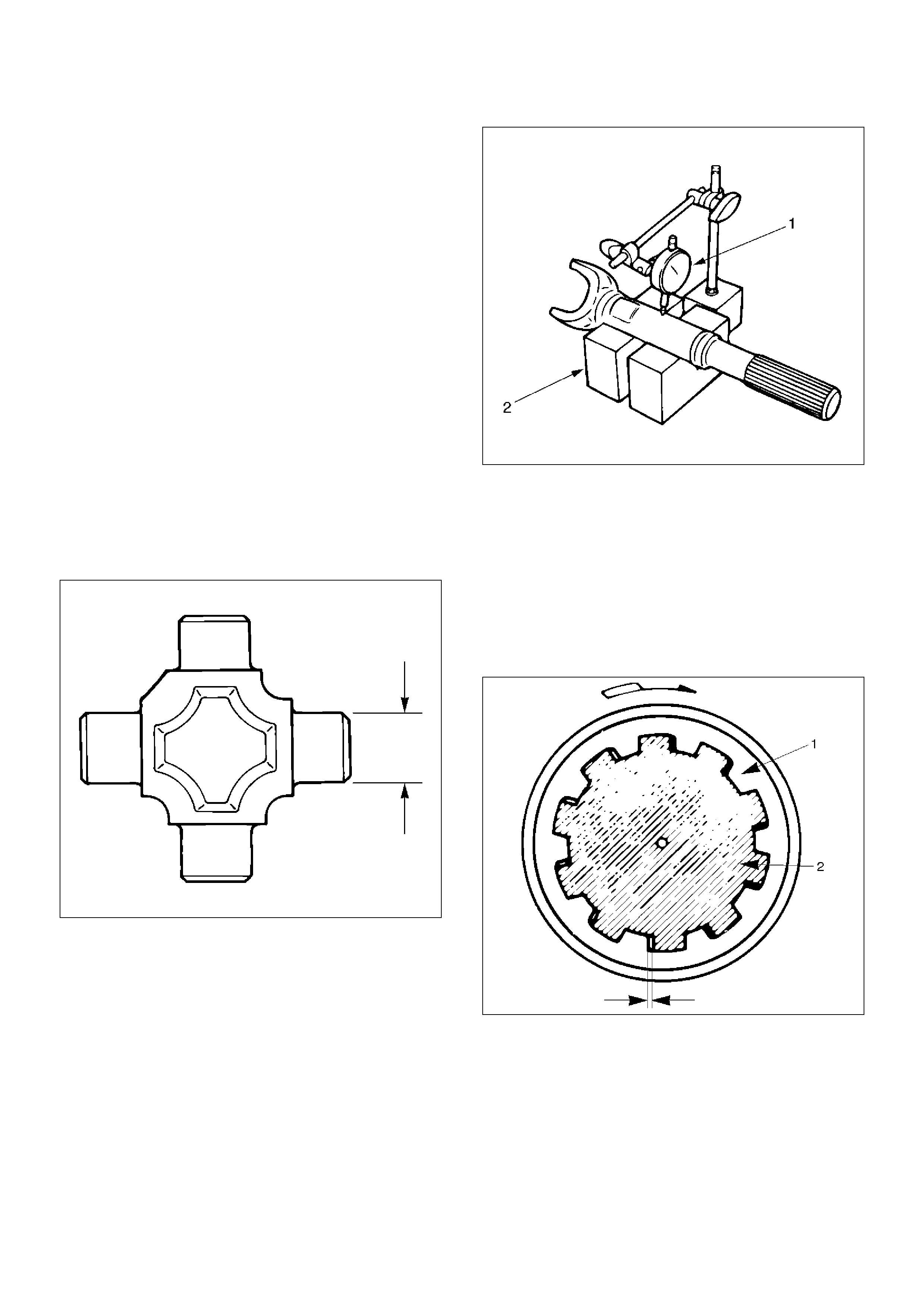
Outside Diameter of Spider Pin
Standard:17.00mm (0.669in)
Limit:16.90mm (0.665in)
401RS007
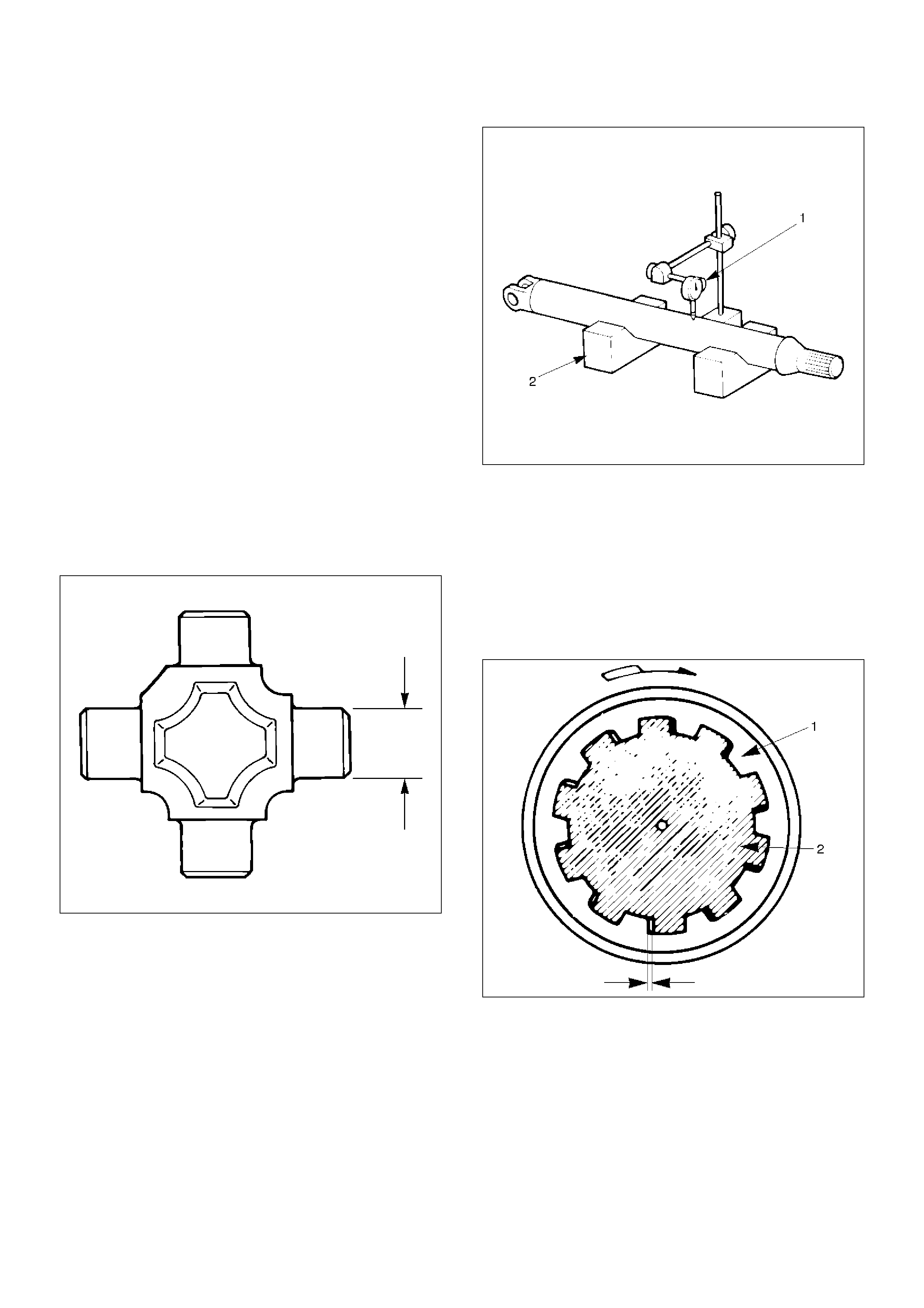
Propeller Shaft Run–out
Support the ends of the propeller shaft on V-blocks (2)
and check for run–out by holding the probe of a dial
indicator (1) in contact with the center part of the shaft. If
the amount of run–out is beyond the standard value for
assembly, correct with a bench press or replace the
shaft with a new propeller shaft assembly.
Standard:0.3mm (0.012in)
Limit:0.5mm (0.02in)
401RS027
Play in Splines in Normal Direction of
Rotation
Check the amount of play between the sleeve yoke (1)
and the propeller shaft spline (2) in the direction of
rotation, using a pointed feeler gauge.
Standard:0.073 – 0.156mm (0.003 – 0.006in)
Limit:0.3mm (0.012in)
401RS009
Play in Universal Joint
Limit:Less than0.1mm (0.004in)
401RS010
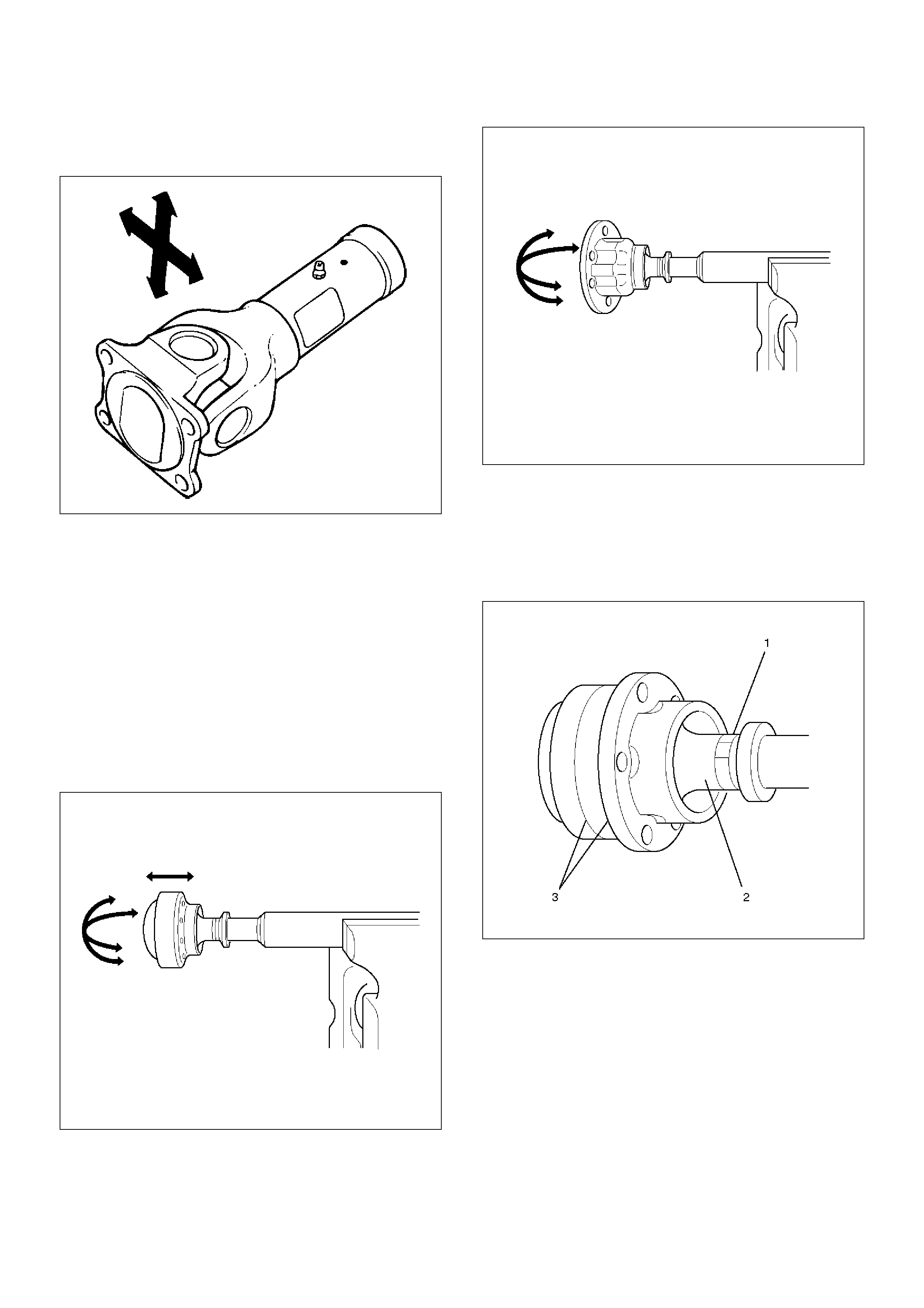
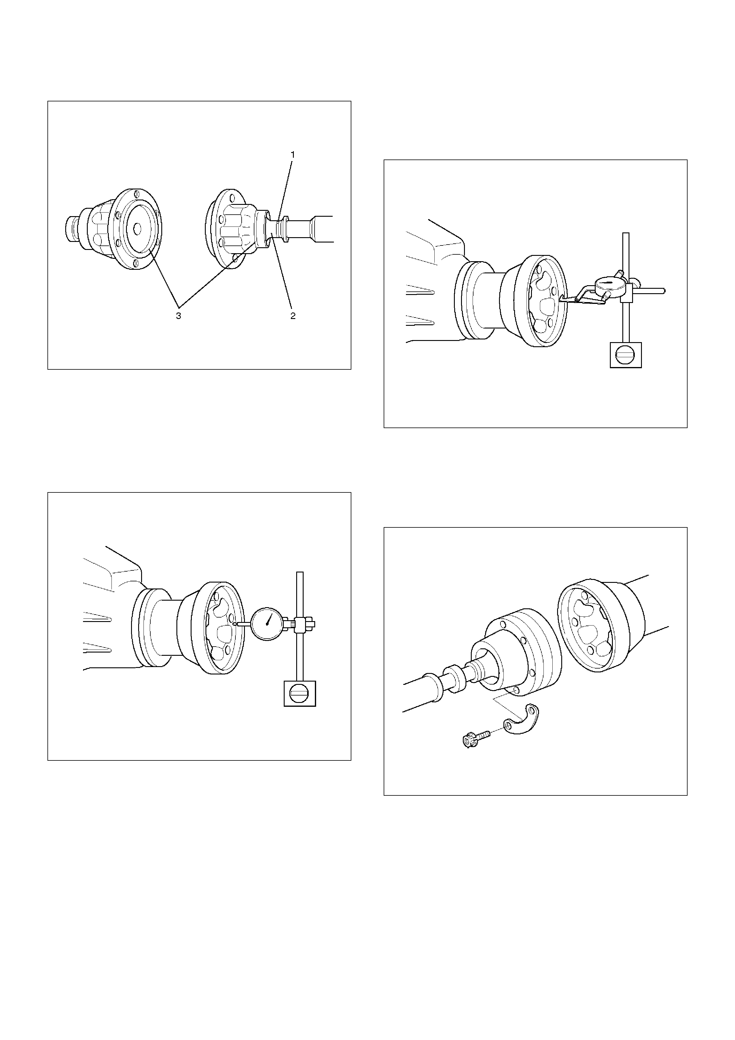
Constant Velocity Joint
NOTE: LJ and BJ constant velocity joints are
unremovable types. Check the joint for play and the
boot for damage, wear, and leak of grease. If
abnormality is found, replace propeller shaft as an
assembly.
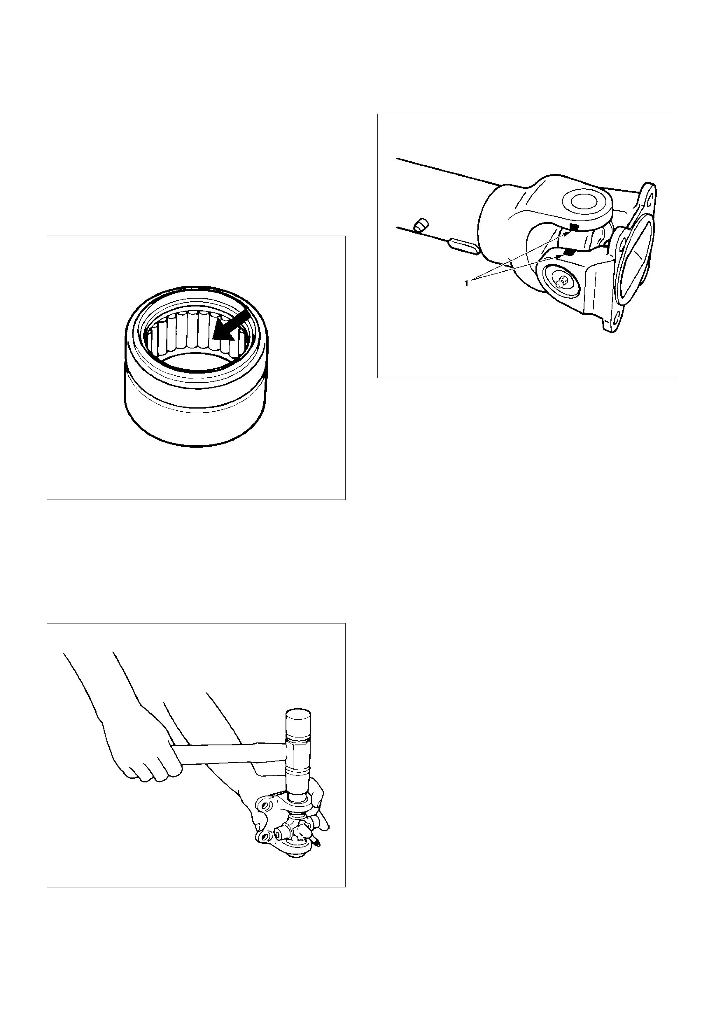
Play in Constant Velocity Joint
Fix the shaft in a vise throrgh pieces of wood, and try to
move the joint vertically, right and left, and back and
forth to make sure of smooth motions and no
remarkable play.
401RW050
401RW049
Boot of Constant Velocity Joint
Check the boot (2) for crack, damage and grease leak,
and the boot band (1) for loosening and damage. Check
the both sides of the joint and make sure that there is no
leak of grease from the cover press-in parts(3).
401RW048
401RW047
Front Axle Flange Run-out
1. Set a dial gage at right angle near the outer
circumference of the flange face and check the
run-out of the flange face.
Limit:0.15mm (0.006in)
401RW046
2. Set a dial gage at right angle near the inner
circumference and check the run-out of the flange.
Limit:0.15mm (0.006in)
401RW045
3. If vibration is felt during the 4H AUTO drive,
disconnct the propeller shaft at the front axle.
Reinstall the propeller shaft at 60°, 120°, 180°, 240°,
and 300° and conduct test drive in each position
and check if there is vibration.
401RW044
Universal Joint Reassembly
1.Install spider to flange yoke. Be sure to install the
spider by aligning the setting marks made during
disassembly.
2.Apply a molybdenum–disulfide grease or a multi–
purpose type grease NLGI No. 2 to inside of the
bearing cap.
Grease Amount:Approx.1.2g (0.042oz)
401RS011
3.Using either a mallet (or copper hammer) or a
press, install the needle roller bearing into the yoke
so that the snap ring can be installed in its groove.
CAUTION: The needle roller bearing cannot be
installed smoothly if it is set at an incorrect angle
with the flange and excessive hammering will
damage the needle roller bearing.
401RS012
4. Align setting marks (1) and join the yokes.
401RS028
5. Install snap ring.
NOTE: Discard used snap rings and install new ones.
When the bearing cap is in position, select and attach a
snap ring of suitable thickness so that the end play of
the spider pin is held within 0.1 mm (0.004 in).
Snap ring thickness and Identification color
1.5mm (0.059in);Blue
1.53mm (0.060in);White
1.59mm (0.063in);Yellow
1.62mm (0.064in);Green
1.68mm (0.066in);Not colored
NOTE: Be sure to use snap rings of the same thickness
on both sides.
Reassembly (Except TOD 4´4)
401RW057
EndOFCallout
1. Discard used seal and install new one.
2. Align the alignment marks and install tube assembly
to sleeve yoke.
Legend
(1) Sleeve Yoke
(2) Seal
(3) Tube Assembly
Main Data and Specifications
General Specifications
Torque Specifications
E04RW021
Engine 6VE1 (3.5L) 4JX1 (3.0L)
Transmission
M/T A/T
A/T
with
TOD
M/T A/T
Construction
Hollow steel tube
with yoke and
spider type
universal joint
Hollow
steel
tube with
constant
velocity
joints
Hollow steel tube
with yoke and
spider type
universal joint
Outside
diameter 40.0mm (1.57 in)
Length 559mm
(22.01in)
559mm
(22.01in)
577mm
(22.72in)
627mm
(24.69in)
627mm
(24.69in)
Rear Propeller Shaft
General Description
Since the propeller shaft is balanced carefully, welding
or any other modifications are not permitted.
Alignment marks should be applied to each propeller
shaft before removal.
401RW003
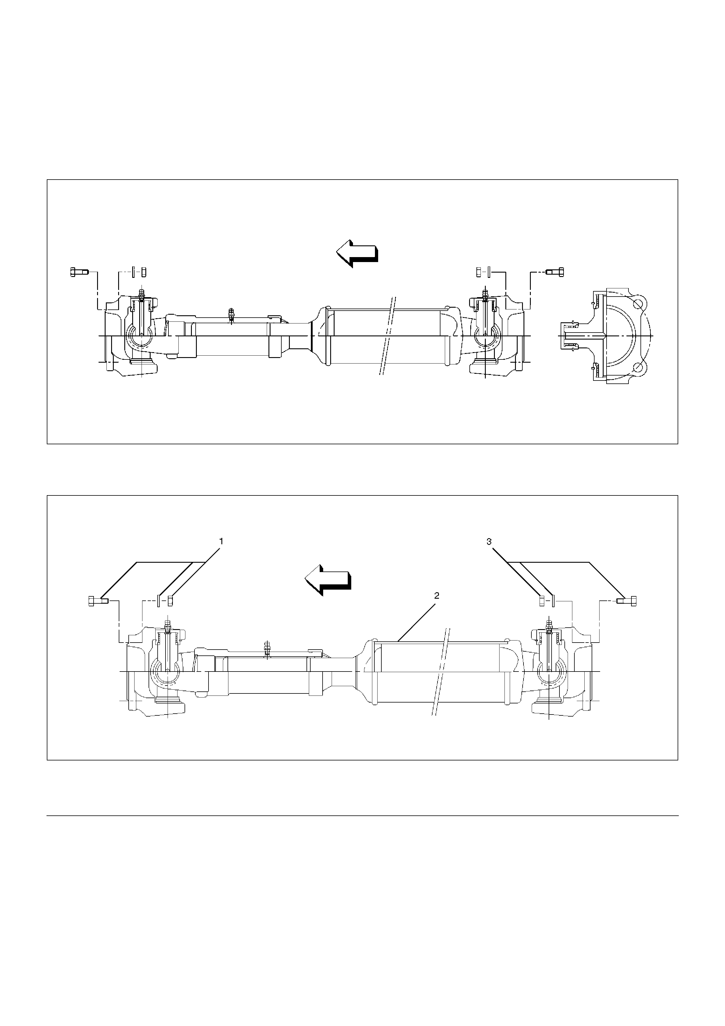
Rear Propeller Shaft and Associated Parts
401RW059
EndOFCallout
Legend
(1) Bolt, Nut and Washer
(2) Rear Propeller Shaft
(3) Bolt, Nut and Washer
Removal
1. Jack up the vehicle and support it on the chassis
stands.
2. Gear shift lever should be placed in neutral position
and parking brake released.
NOTE: Apply alignment marks on the flange at the rear
propeller shaft both front and rear side.
401RS023
3. Remove bolt, nut and washer (Rear axle side).
4. Remove bolt, nut and washer (Transfer side).
5. Remove rear propeller shaft.
Installation
NOTE: Never install the shaft assembly backwards.
1. Completely remove the black paint from the
connecting surface of flange coupling on each end
of propeller shaft. Clean so that no foreign matter
will be caught in between.
2. Align the mark which is applied at removal .
Install rear propeller shaft and tighten the bolts to
the specified torque.
Torque:63N·m (6.4kg·m/46lbft)
3. After installing the propeller shaft, be sure to apply
black paint (1) to exposed area (other than
connecting surface) of the entire surface of flange
coupling .
401RS022

Disassembly
401RW057
EndOFCallout
1. Apply alignment marks (1) on the sleeve yoke and
tube assembly then remove sleeve yoke.
401RW056
2. Remove seal.
3. Remove tube assembly.
Legend
(1) Sleeve Yoke
(2) Seal
(3) Tube Assembly
Universal Joint Disassembly
401RW054
EndOFCallout
1. Apply alignment marks (1) on the yokes of the
universal joint, then remove snap ring.
401RS028
2. Tap out the needle roller bearing by gently striking
the shoulder of the yoke, using a mallet or a copper
hammer.
401RS006
Legend
(1) Flange Yoke
(2) Spider with Grease Fitting
(3) Snap Ring
(4) Needle Roller Bearing
(5) Grease Fitting
3. Make sure of proper position for reinstallation by
applying setting marks, then remove spider with
grease fitting.
Inspection and Repair
Make necessary correction or parts replacement if wear,
damage, corrosion or any other abnormal condition is
found through inspection.
NOTE: When any part of the journal assembly (spider,
needle roller bearing, grease fitting) requires
replacement, be sure to replace the entire assembly.
Check the following parts for wear, damage, noise or
any other abnormal conditions:
1. Spider
2. Needle roller bearing
3. Yoke
4. Flange
Outside Diameter of Spider Pin
Standard:17.00mm (0.669in)
Limit:16.90mm (0.665in)
401RS007
Propeller Shaft Run-out
Support the ends of the propeller shaft on V-blocks (2)
and check for run-out by holding the probe of a dial
indicator (1) in contact with the center part of the shaft.
If the amount of run-out is beyond the standard value for
assembly, correct with a bench press or replace the
shaft with a new propeller shaft assembly .
Standard:0.3mm (0.012in)
Limit:0.5mm (0.02in)
401RS008
Play in Splines in Normal Direction of
Rotation
Check the amount of play between the sleeve yoke (1)
and the propeller shaft spline (2) in the direction of
rotation, using a pointed feeler gauge.
Standard:0.073 – 0.156mm (0.003 – 0.006in)
Limit:0.3mm (0.012in)
401RS009
Play in Universal Joint
Limit:Less than0.1mm (0.004in)
401RS010
Universal Joint Reassembly
1.Install spider to flange yoke. Be sure to install the
spider by aligning the setting marks made during
disassembly.
2.Before installing needle roller bearing, apply a
molybdenum–disulfide grease or a multi–purpose
type grease NLGI No. 2 to inside of the bearing cap.
Grease Amount:Approx.1.2g (0.042oz)
401RS011
3.Using either a mallet (or copper hammer) or a
press, install the needle roller bearing into the yoke
so that the snap ring can be installed in its groove.
CAUTION: The needle roller bearing cannot be
installed smoothly if it is set at an incorrect angle
with the flange and excessive hammering will
damage the needle roller bearing.
401RS012
4. Align setting marks (1) and join the yokes.
NOTE: Assemble the spider and spline yoke so that
their grease fittings are arranged on the same side.
401RS028
5. Install snap ring.
NOTE: Discard used snap rings and install new ones.
When the bearing cap is in position, select and attach a
snap ring of suitable thickness so that the end play of
the spider pin is held within 0.1 mm (0.004 in).
Snap ring thickness and identification color
1.5mm (0.059in):Blue
1.545mm (0.061in):White
1.59mm (0.063in):Yellow
1.635mm (0.064in):Green
1.68mm (0.066in):Not colored
NOTE: Be sure to use snap rings of the same thickness
on both sides.

Reassembly
401RW057
EndOFCallout
1. Discard used seal and install new one.
2. Align the alignment marks and install tube assembly
to sleeve yoke.
Legend
(1) Sleeve Yoke
(2) Seal
(3) Tube Assembly
Main Data and Specifications
General Specifications
Torque Specifications
E04RW023
Engine 6VE1 (3.5L) 4JX1 (3.0L)
Transmission
M/T A/T
A/T
with
TOD
M/T A/T
Construction Hollow steel tube with yoke and spider type
universal joint
Length
1093mm (43.03in) 1075mm
(42.32in) 1029mm (40.51in)
Outside
diameter 68.9mm (2.71in)