
SECTION 5A - BRAKE CONTROL SYSTEM
Service Precaution
General Description
System Components
Electronic Hydraulic Control Unit (EHCU)
ABS Warning Light
Wheel Speed Sensor
G-Sensor
Normal and Anti-lock Braking
Brake Pedal Travel
Acronyms and Abbreviations
General Diagnosis
General Information
ABS Service Precautions
Computer System Service Precautions
General Service Precautions
Note on Intermittents
Test Driving ABS Complaint Vehicles
“ABS” Warning Light
Normal Operation
Basic Diagnostic Flow Chart
Basic Inspection Procedure
Tech 2 Scan Tool
Using Tech 2 On The Vehicle
Connecting TECH 2 To The Vehicle
Chassis Application Menu
- Antilock Braking System (Abs)
ABS Tech 2 Functions
Data List
EHCU Connector Pin-out Checks
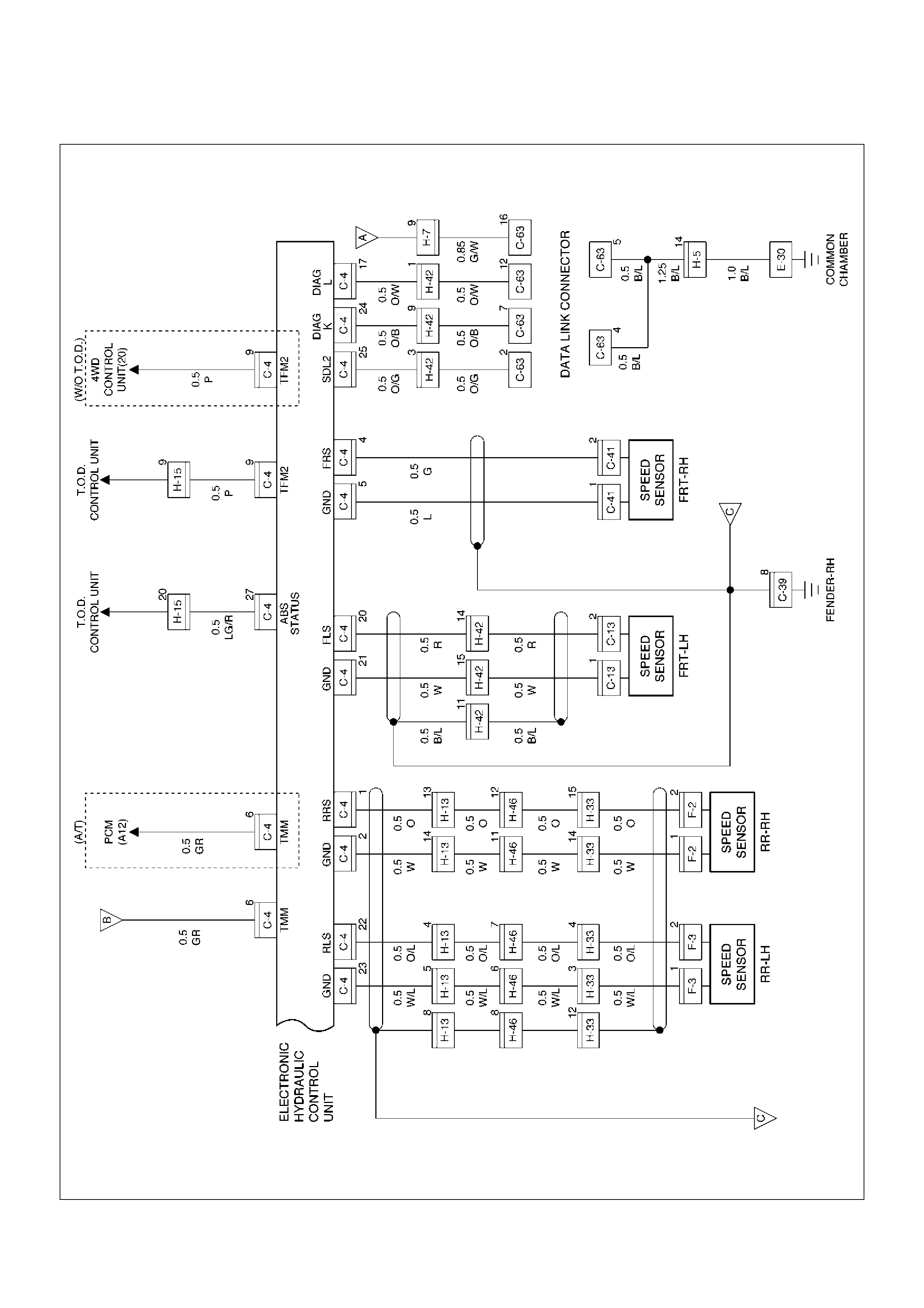
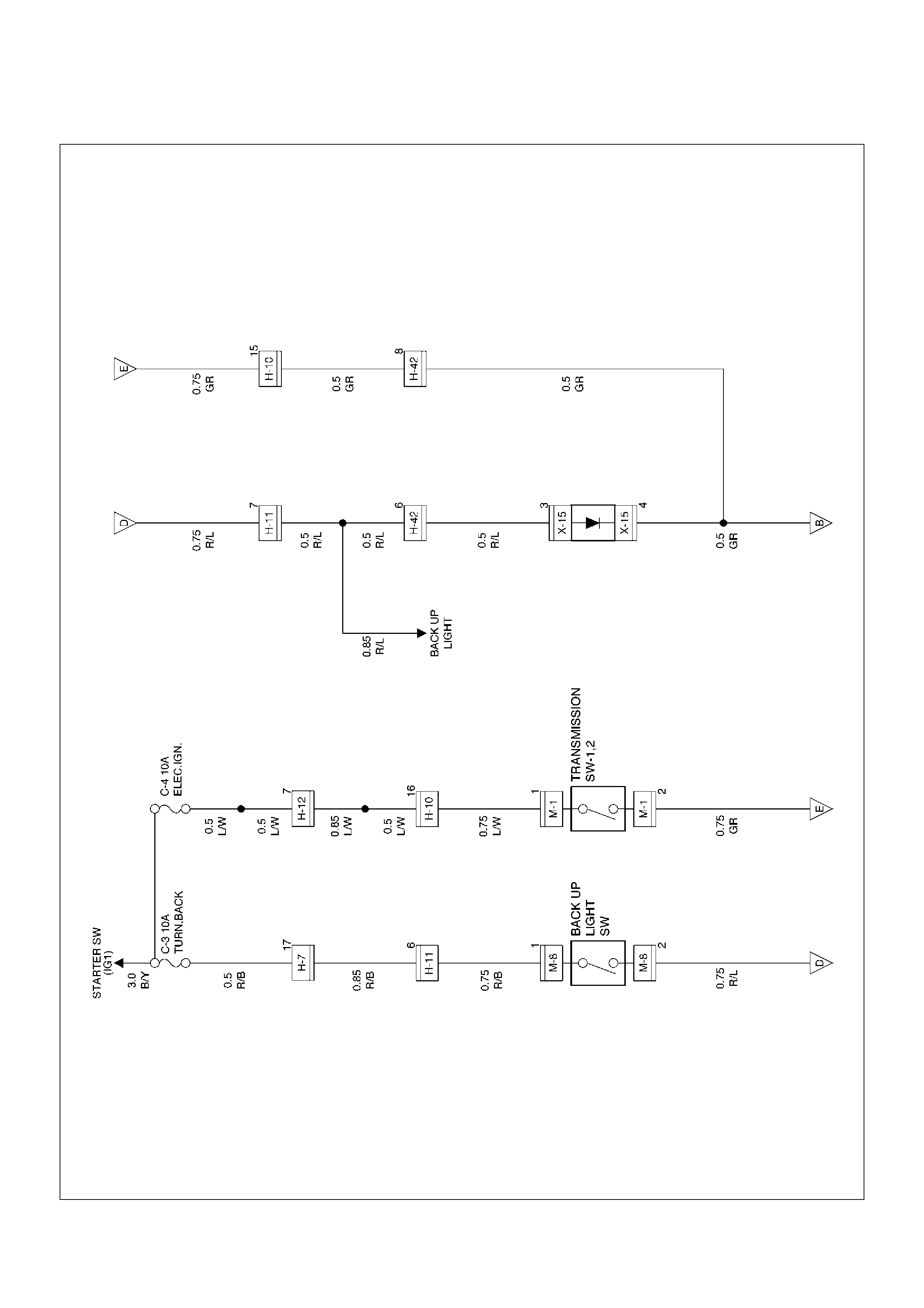
Circuit Diagram ( 6VE1 and 4JX1)
Circuit Diagram ( 4JX1)
Circuit Diagram ( 4JX1)
Circuit Diagram ( 6VE1)
Circuit Diagram ( 6VE1)
Connector List
Part Location
Symptom Diagnosis
Chart A–1 ABS Works Frequently But Vehicle Does
Not Decelerate
Chart TA-1 ABS Works Frequently But Vehicle Does
Not Decelerate (Use TECH 2)
Chart A-2 Uneven Braking Occurs While ABS Works
Chart A-3, TA-3 The Wheels Are Locked
Chart A-4 Abnormal Brake Pedal ‘Feel’
Chart A-5, TA-5 Braking Sound (From EHCU) Is
Heard While Not Braking
Diagnostic Trouble Codes
Diagnosis By “ABS” Warning
Light Illumination Pattern
Diagnostic Trouble Codes (DTCs)
Chart B-1 With the key in the ON position (Before
starting the engine). Warning light (W/L) is not
activated.
Chart B-2 EHCU Abnormality (DTC 14)
Chart B-3 Power Voltage Drop (DTC 15)
Chart B-4 CLASS-2 Communication Line
Abnormality (DTC 16)
Chart B-5 G-Sensor Circuit (DTC 21)
Chart B-6 Abnormal Transmission Input (DTC 23)
Chart B-7 Transfer Monitor (DTC 24)
Chart B-8 EHCU Pump Motor And Motor Relay
Circuit (DTC 32)
Chart B-9 EHCU Pump Valve And Valve Relay
Circuit (DTC 35)
Chart B-10 FL Isolation Solenoid Valve Abnormality
(DTC 41)
Chart B-11 FL Dump Solenoid Valve Abnormality
(DTC 42)
Chart B-12 FR Isolation Solenoid Valve Abnormality
(DTC 43)
Chart B-13 FR Dump Solenoid Valve Abnormality
(DTC 44)
Chart B-14 Rear Isolation Solenoid Valve
Abnormality (DTC 45)
Chart B-15 Rear Dump Solenoid Valve Abnormality
(DTC 46)
Chart B-16 FL Speed Sensor Disconnection
(DTC 51)
Chart B-17 FR Speed Sensor Disconnection
(DTC 52)
Chart B-18 RL Speed Sensor Disconnection
(DTC 53)
Chart B-19 RR Speed Sensor Disconnection
(DTC 54)
Chart B-20 FL Speed Sensor Short Circuit (DTC 61)
Chart B-21 FR Speed Sensor Short Circuit (DTC 62)
Chart B-22 RL Speed Sensor Short Circuit (DTC 63)
Chart B-23 RR Speed Sensor Short Circuit (DTC 64)
Chart B-24 Sensor Signal Input Abnormality
(DTC 65)
Sensor Signal Abnormality Criteria using TECH 2

Unit Inspection Procedure
Chart C-1-1 FL Sensor Output Inspection Procedure
Chart C-1-2 FR Sensor Output Inspection Procedure
Chart C-1-3 RL Sensor Output Inspection Procedure
Chart C-1-4 RR Sensor Output Inspection
Procedure
Chart TC-1 Sensor Output Inspection Procedure
(Use TECH 2)
Chart C-2 Transmission Input Inspection Procedure
Chart TC-2 Transmission Input Inspection
Procedure (Use TECH 2)
Special Tools
Service Precaution
WARNING: IF SO EQUIPPED WITH A
SUPPLEMENTAL RESTRAINT SYSTEM (SRS),
REFER TO THE SRS COMPONENT AND WIRING
LOCATION VIEW IN ORDER TO DETERMINE
WHETHER YOU ARE PERFORMING SERVICE ON
OR NEAR THE SRS COMPONENTS OR THE SRS
WIRING. WHEN YOU ARE PERFORMING SERVICE
ON OR NEAR THE SRS COMPONENTS OR THE
SRS WIRING, REFER TO THE SRS SERVICE
INFORMATION. FAILURE TO FOLLOW WARNINGS
COULD RESULT IN POSSIBLE AIR BAG
DEPLOYMENT, PERSONAL INJURY, OR
OTHERWISE UNNEEDED SRS SYSTEM REPAIRS.
CAUTION: Always use the correct fastener in the
proper location. When you replace a fastener, use
ONLY the exact part number for that application.
HOLDEN will call out those fasteners that require a
replacement after removal. HOLDEN will also call
out the fasteners that require thread lockers or
thread sealant. UNLESS OTHERWISE SPECIFIED,
do not use supplemental coatings (Paints, greases,
or other corrosion inhibitors) on threaded fasteners
or fastener joint interfaces. Generally, such
coatings adversely affect the fastener torque and
the joint clamping force, and may damage the
fastener. When you install fasteners, use the correct
tightening sequence and specifications. Following
these instructions can help you avoid damage to
parts and systems.
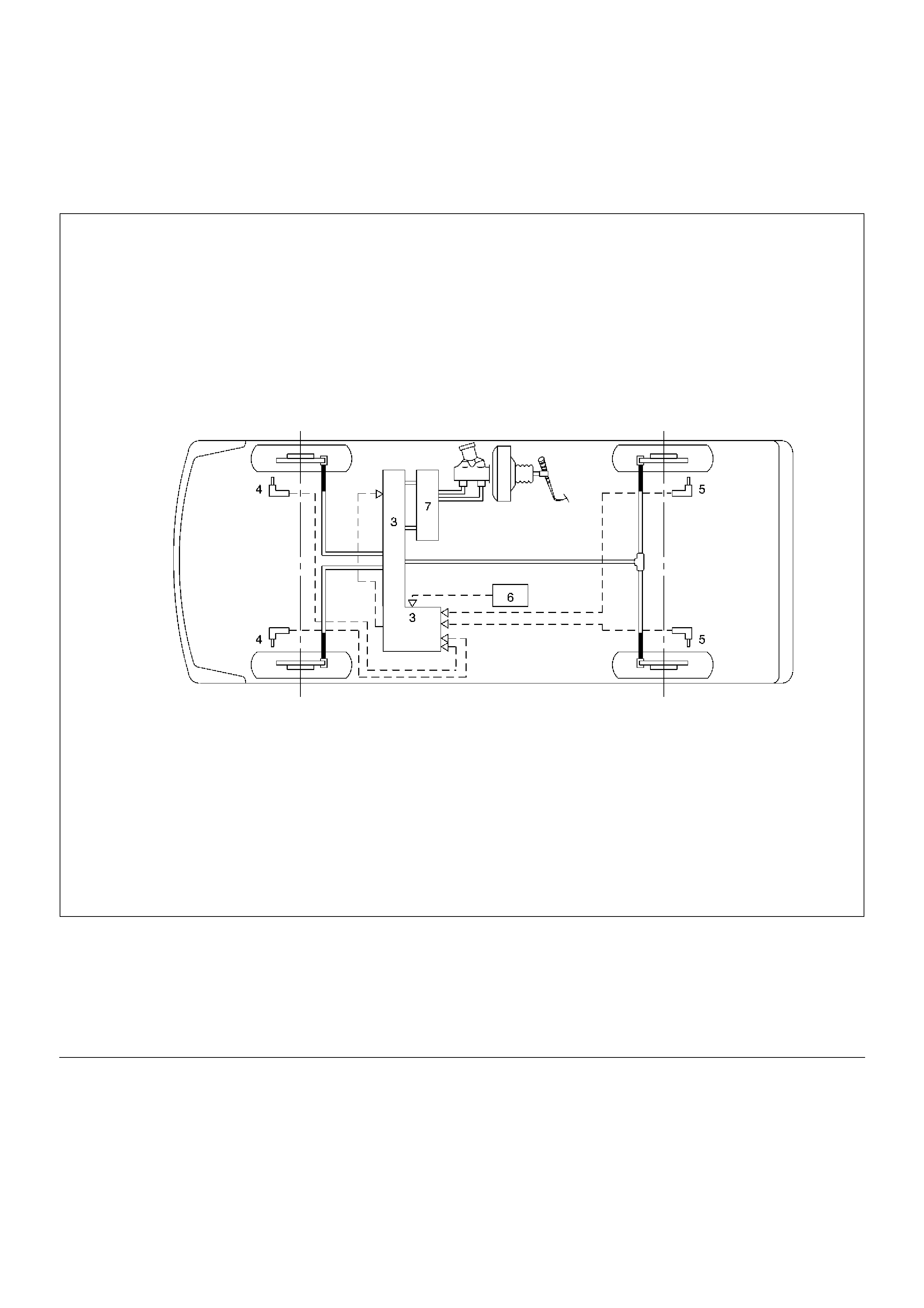
General Description
The Anti-lock Brake System (ABS) works on all four
wheels. A combination of wheel speed sensor and
Electronic Hydraulic Control Unit (EHCU) can determine
when a wheel is about to stop turning and adjust brake
pressure to maintain best braking.
This system helps the driver maintain greater control of
the vehicle under heavy braking conditions.
C05RW027
Legend
(3) Electronic Hydraulic Control Unit (EHCU)
(4) Front Wheel Speed Sensor
(5) Rear Wheel Speed Sensor
(6) G-Sensor
(7) Proportioning and Bypass (P&B) Valve
(9) Electronic Line
(10) Hydraulic Line
System Components
Electronic Hydraulic Control Unit (EHCU), four Wheel
Speed Sensors, Warning Light, and G-sensor.
Electronic Hydraulic Control Unit (EHCU)
The EHCU consists of ABS control circuits, fault
detector, and a fail-safe. It drives the hydraulic unit
according to the signal from each sensor, cancelling
ABS to return to normal braking when a malfunction has
occurred in the ABS.
The EHCU has a self-diagnosing function which can
indicate faulty circuits during diagnosis.
The EHCU is mounted on the engine compartment front
right side. It consists of a Motor, Plunger Pump,
Solenoid Valves and Check Valve.
On the outside, the relay box containing a motor relay
and a valve relay is installed.
Solenoid Valves: Reduces or holds the caliper fluid
pressure for each front disc brake or both rear disc
brakes according to the signal sent from the EHCU.
Reservoir: Temporarily holds the brake fluid that returns
from the front and rear disc brake caliper so that
pressure of front disc brake caliper can be reduced
smoothly.
Plunger Pump: Feeds the brake fluid held in the
reservoir to the master cylinder.
Motor: Drives the pump according to the signal from
EHCU.
Check Valve: Controls the brake fluid flow.
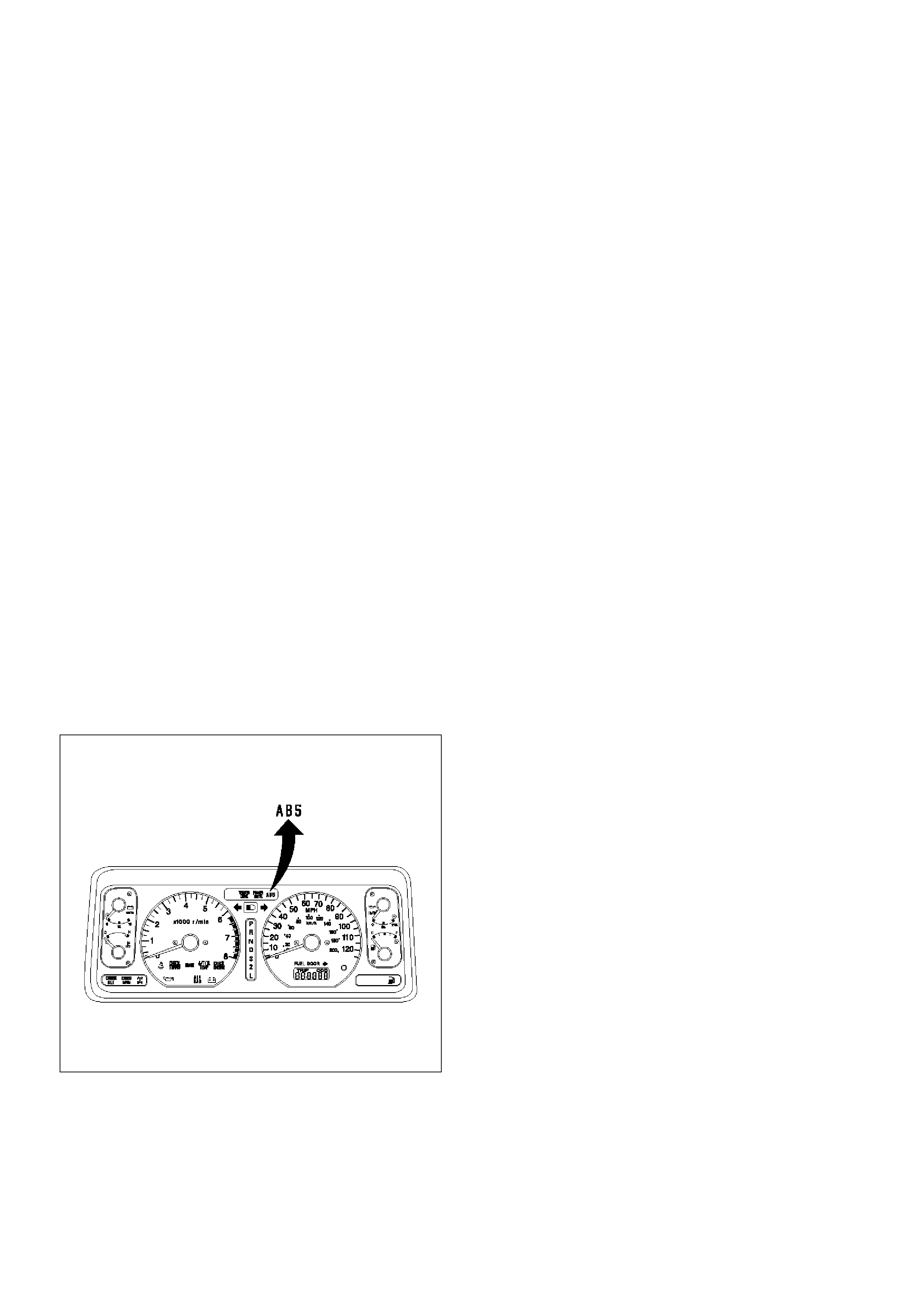
ABS Warning Light
821RW033
Vehicles equipped with the Anti-lock Brake System
have an amber “ABS” warning light in the instrument
panel. The “ABS” warning light will illuminate if a
malfunction in the Anti-lock Brake System is detected
by the Electronic Hydraulic Control Unit (EHCU). In
case of an electronic malfunction, the EHCU will turn
“ON” the “ABS” warning light and disable the Anti-lock
braking function.
The “ABS” light will turn “ON” for approximately three
seconds after the ignition switch is to the “ON” position.
If the “ABS” light stays “ON” after the ignition switch is
the “ON” position, or comes “ON”and stays “ON” while
driving, the Anti-lock Brake System should be inspected
for a malfunction according to the diagnosis procedure.
Wheel Speed Sensor
It consists of a sensor and a rotor. The sensor is
attached to the knuckle on the front wheels and to the
axle shaft bearing holder on the rear wheels.
The rotor is press-fit in the axle shaft.
The flux generated from electrodes magnetized by a
magnet in the sensor varies due to rotation of the rotor,
and the electromagnetic induction generates alternating
voltage in the coil. This voltage draws a “sine curve”
with the frequency proportional to rotor speed and it
allows detection of wheel speed.
G-Sensor
The G-sensor installed inside the center console
detects the vehicle deceleration speed and sends a
signal to the EHCU. In 4WD operation, all four wheels
may be decelerated in almost the same phase, since all
wheels are connected mechanically.
This tendency is noticeable particularly on roads with
low friction coefficient, and the ABS control is adversely
affected.
The G-sensor judges whether the friction coefficient of
road surface is low or high, and changes the EHCU's
operating system to ensure ABS control.
Normal and Anti-lock Braking
Under normal driving conditions, the Anti-lock Brake
System functions the same as a standard power
assisted brake system. However, with the detection of
wheel lock-up, a slight bump or kick-back will be felt in
the brake pedal. This pedal “bump” will be followed by a
series of short pedal pulsations which occurs in rapid
succession. The brake pedal pulsation will continue
until there is no longer a need for the anti-lock function
or until the vehicle is stopped. A slight ticking or popping
noise may be heard during brake applications when the
Anti-lock features is being used.
When the Anti-lock feature is being used, the brake
pedal may rise even as the brakes are being applied.
This is also normal. Maintaining a constant force on the
pedal will provide the shortest stopping distance.
Brake Pedal Travel
Vehicles equipped with the Anti-lock Brake System may
be stopped by applying normal force to the brake
pedal. Although there is no need to push the pedal
beyond the point where it stops or holds the vehicle, by
applying more force the pedal will continue to travel
toward the floor.

This extra brake pedal travel is normal.
Acronyms and Abbreviations
Several acronyms and abbreviations are commonly
used throughout this section:
ABS
Anti-lock Brake System
CKT
Circuit
DLC
Data Link Connector
EHCU
Electronic Hydraulic Control Unit
FL
Front Left
FR
Front Right
GEN
Generator
MV
Millivolts
RL
Rear Left
RR
Rear Right
RPS
Revolution per Second
VDC
Volts DC
VAC
Volts AC
W/L
Warning Light
WSS
Wheel Speed Sensor
General Diagnosis
General Information
ABS malfunction can be classified into two types, those
which can be detected by the ABS warning light and
those which can be detected as a vehicle abnormality
by the driver.
In either case, locate the fault in accordance with the
“BASIC DIAGNOSTIC FLOWCHART” and repair.
Please refer to Section 5C for the diagnosis of
mechanical troubles such as brake noise, brake judder
(brake pedal or vehicle vibration felt when braking),
uneven braking, and parking brake trouble.
ABS Service Precautions
Required Tools and Items:
• Box Wrench
•Brake Fluid
• Special Tool
Some diagnosis procedures in this section require the
installation of a special tool.
J-39200 High Impedance Multimeter
When circuit measurements are requested, use a circuit
tester with high impedance.
Computer System Service Precautions
The Anti-lock Brake System interfaces directly with the
Electronic Hydraulic Control Unit (EHCU) which is a
control computer that is similar in some regards to the
Powertrain Control Module. These modules are
designed to withstand normal current draws associated
with vehicle operation. However, care must be taken to
avoid overloading any of the EHCU circuits. In testing
for opens or shorts, do not ground or apply voltage to
any of the circuits unless instructed to do so by the
appropriate diagnostic procedure. These circuits should
only be tested with a high impedance multimeter
(J-39200) or special tools as described in this section.
Power should never be removed or applied to any
control module with the ignition in the “ON” position.
Before removing or connecting battery cables, fuses or
connectors, always turn the ignition switch to the “OFF”
position.
General Service Precautions
The following are general precautions which should be
observed when servicing and diagnosing the Anti-lock
Brake System and/or other vehicle systems. Failure to
observe these precautions may result in Anti-lock
Brake System damage.
• If welding work is to be performed on the vehicle
using an electric arc welder, the EHCU and valve
block connectors should be disconnected before the
welding operation begins.
• The EHCU and valve block connectors should never
be connected or disconnected with the ignition “ON” .
• EHCU of the Anti-lock Brake System are not
separately serviceable and must be replaced as
assemblies. Do not disassemble any component
which is designated as non-serviceable in this
Section.
• If only rear wheels are rotated using jacks or drum
tester, the system will diagnose a speed sensor
malfunction and the “ABS” warning light will
illuminate. But actually no trouble exists. After
inspection stop the engine once and re-start it, then

make sure that the “ABS” warning light does not
illuminate.
If the battery has been discharged
The engine may stall if the battery has been completely
discharged and the engine is started via jumper cables.
This is because the Anti-lock Brake System (ABS)
requires a large quantity of electricity. In this case, wait
until the battery is recharged, or set the ABS to a
non-operative state by removing the fuse for the ABS
(40A). After the battery has been recharged, stop the
engine and install the ABS fuse. Start the engine again,
and confirm that the ABS warning light does not light.
Note on Intermittents
As with virtually any electronic system, it is difficult to
identify an intermittent failure. In such a case duplicating
the system malfunction during a test drive or a good
description of vehicle behavior from the customer may
be helpful in locating a “most likely” failed component or
circuit. The symptom diagnosis chart may also be useful
in isolating the failure. Most intermittent problems are
caused by faulty electrical connections or wiring. When
an intermittent failure is encountered, check suspect
circuits for:
• Suspected harness damage.
• Poor mating of connector halves or terminals not fully
seated in the connector body (backed out).
• Improperly formed or damaged terminals.
Test Driving ABS Complaint Vehicles
In case that there has been an malfunction in the
lighting pattern of “ABS” warning light, the fault can be
located in accordance with the “DIAGNOSIS BY “ABS”
WARNING LIGHT ILLUMINATION PATTERN" . In case
of such trouble as can be detected by the driver as a
vehicle symptom, however, it is necessary to give a test
drive following the test procedure mentioned below,
thereby reproducing the symptom for trouble diagnosis
on a symptom basis:
1. Start the engine and make sure that the “ABS” W/L
goes OFF. If the W/L remains ON, it means that the
Diagnostic Trouble Code (DTC) is stored.
Therefore, read the code and locate the fault.
2. Start the vehicle and accelerate to about 30 km/h
(19 mph) or more.
3. Slowly brake and stop the vehicle completely.
4. Then restart the vehicle and accelerate to about
40 km/h (25 mph) or more.
5. Brake at a time so as to actuate the ABS and stop
the vehicle.
6. Be cautious of abnormality during the test. If the W/
L is actuated while driving, read the DTC and locate
the fault.
7. If the abnormality is not reproduced by the test,
make best efforts to reproduce the situation
reported by the customer.
8. If the abnormality has been detected, repair in
accordance with the “SYMPTOM DIAGNOSIS” .
NOTE:
• Be sure to give a test drive on a wide, even road with
little traffic.
• If an abnormality is detected, be sure to suspend the
test and start trouble diagnosis at once.
“ABS” Warning Light
When ABS trouble occurs and actuates when possible
the “ABS” warning light, the trouble code corresponding
to the trouble is stored in the EHCU. Only the ordinary
brake system is available when the ABS is turned off.
When the “ABS” warning light is actuated, if the starter
switch is set ON after setting it OFF once, the EHCU
checks up on the entire system and, if there is no
abnormality, judges ABS to work currently and the
warning light works normally even though the trouble
code is stored.
NOTE: Illumination of the “ABS” warning light indicates
that anti-lock braking is no longer available. Power
assisted braking without anti-lock control is still
available.
Normal Operation
“ABS” Warning Light
When the ignition is first moved from “OFF” to “RUN” ,
the amber “ABS” warning light will turn “ON” . The “ABS”
warning light will turn “ON” during engine starting and
will usually stay “ON” for approximately three seconds
after the ignition switch is returned to the “ON” position.
The warning light should remain “OFF” at all other
times.

Basic Diagnostic Flow Chart
Basic Inspection Procedure 1. Basic Inspection of System Brake
2. Inspection of Front Axle Switch
3. Ground Inspection
Step Action Yes No
1 1. Customer complaint.
2. Questioning to customer.
3. Basic inspection (Refer to“Basic inspection procedure”)
Using TECH 2? Go to Step 2 Go to Step 4
2 Make sure of DTC by mode“F0: Diagnostic Trouble Codes”.
Is EHCU including DTC? Go to Step 3 Go to Step 5
3 1. Repair of faulty part.
2. Elimination of DTC.
3. Inspection of “ABS” W/L Illumination pattern with ignition
SW“ON”.
4. Test drive.
Does repeat trouble?
Repeat the
diagnosis it the
symptom or DTC
appears again Go
to Step 1 Go to Step 5
4 Check if the DTC is stored.
Is EHCU including DTC?
Go to Step 3
Trouble diagnosis
based on symptom
(Refer
to“SYMPTOM
DIAGNOSIS”) Go
to Step 3
5 1. Reconnect all components and ensure all component are
properly mounted.
2. Clear diagnostic trouble code.
Was this step finished? Finished Go to Step 5
Step Action Yes No
1 Is the fluid level normal?
Go to Step 2
Replenish with
fluid.
Go to Step 2
2 Does fluid leak? Repair.
Go to Step 3 Go to Step 3
3 Is the booster functioning normal?
Go to Step 4
Repair.
Go to Step 4
4 Is the pad and rotor normal?
Go to Step 5
Repair.
Go to Step 5
5 Reconnect all components and ensure all component are
properly mounted.
Was this step finished? Finished Go to Step 5
Step Action Yes No
1 Turn the key switch on and shift the T/F to 4WD position.
Does the 4WD light come on? Go to Step 2
Repair.
Go to Step 2
2 Reconnect all components and ensure all components are
properly mounted.
Was this step finished? Finished Go to Step 2
Step Action Yes No
1 Are ABS—related ground points ok?
Go to Step 2
Repair.
Go to Step 2
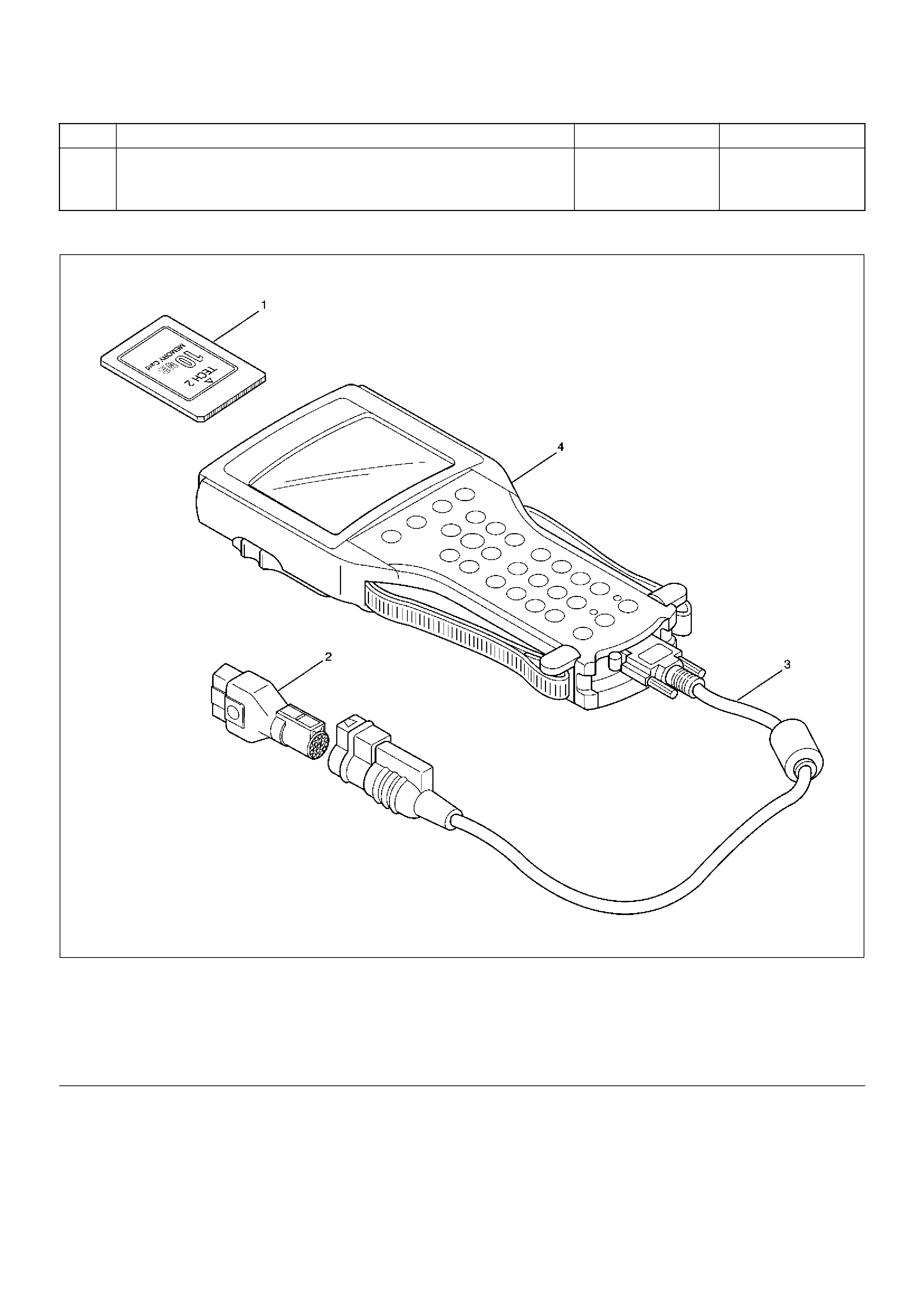
Tech 2 Scan Tool
901RW257
EndOFCallout
2 Reconnect all components and ensure all components are
properly mounted.
Was this step finished? Finished Go to Step 2
Step Action Yes No
Legend
(1) PCMCIA Card
(2) SAE 16/19 Adaptor
(3) DLC Cable
(4) Tech–2
Using Tech 2 On The Vehicle
NOTE: Due to the constant evolution of TECH 2
software, the screens shown in this section may
differ slightly from those displayed for the vehicle
being tested.
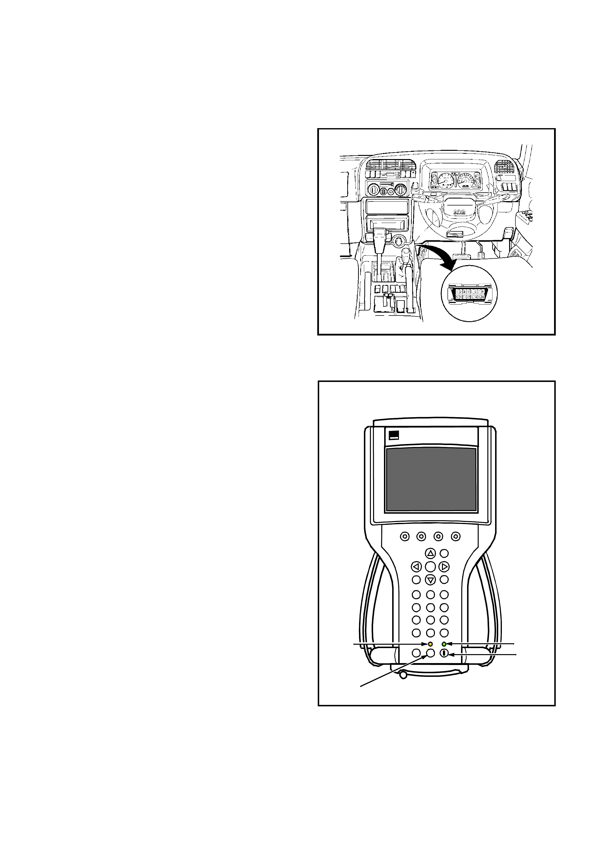
Connecting TECH 2 To The Vehicle
1. Connect Tech 2 to the vehicle DLC, with the DLC
cable and the 16/19 pin adapter.
2. Switch the unit on by pressing the power button (2).
A green light (1) should come on indicating that the
tool is receiving power.
NOTE: At this time the technician should see the Power
On Self Test (POST) run. The POST is a built in
diagnostic self test for the TECH 2 that should find most
common system faults. The POST is run on every
power up to ensure the best operation of the tool. After
the completion of the POST, the TECH 2 unit will briefly
show the POST results. If POST passes, the tool will
continue onto the title screen. If POST fails, results of all
tests will be displayed, and this should show which test
failed. POST failures may be classified as fatal or non-
fatal. A fatal error will not allow the user to continue
using the tool. Failure of the keypad would be an
example of a fatal error. Non-fatal errors found during
the POST will allow continued use of the TECH 2, but
with some limitations. If either a fatal or non-fatal error
occurs, refer to the Troubleshooting section of the
TECH 2 User's Guide.
1. Power Status Indicator Light
2. PWR (Power) Key
3. SHIFT Key
4. SHIFT Key Status Indicator Light
3. At the Tech 2 title screen press the ENTER key to
continue.
PWR
F0
F3
F6
F9
F1
F4
F7
F2
F5
F8
?
GM
TECH 2
2
2
Tech
10 Megabyte
Press [ENTER] to continue
Software Version 11.010
Holden 1997 - 2002
2
1
4
3

4. A selection can be made from the Main Menu,
either by using a function key or by using the arrow
keys to highlight a menu choice and pressing
ENTER.
•NOTE: You will then need to supply some additional
information to the TECH 2. This requires navigation
through a series of lists (called picklists). On some
menus or picklists, the user can use a function key to
make a menu selection, but most of the picklists
require using the selection and action keys. If a
mistake is made in the selection process, or if a
different application or function is desired, press EXIT
to back up one level. Within an application, there may
be soft keys which are available for use. These soft
keys allow access to additional tool functions without
exiting a current tool function. Soft keys are made up
of sets which will appear together. To see the next set
of soft keys, select the More soft key.
The TECH 2 Main Menu contains the following:
F0: Diagnostics
Contains all functions to test, diagnose, monitor and
program the different vehicle systems.
F1: Service Programming System (SPS)
SPS is used in conjunction with Technical
Information System (TIS) 2000 to program vehicle
control units.
F2: View Capture Data
Contains all functions to work with one or two
previously recorded snapshots on one or two
vehicles. This function is to enable the viewing of
captured data without a vehicle.
F3: Tool Options
Contains the TECH 2 self test, set clock, set units,
set screen contrast and Getting Started.
F4: Download/Upload Help
Contains help information on the downloading and
uploading from the TECH 2 to the TIS 2000 CD-
ROM.
System Select Menu
(2) 2002 Jackaroo
F0: Powertrain
F1: Chassis
F2: Body
UBS2002
5. Select the correct Model Year with the arrow keys
and the press ENTER. The Vehicle identification
screen will then be displayed.
6. Select the correct Vehicle Type with the arrow keys
and the press ENTER. The System Select Menu
will then be displayed.
7. The desired system can be selected from the
System Select Menu with the function keys or with
arrow keys and then press ENTER.
F0:Powertrain contains all functions to test,
diagnose, and monitor the engine and transmission
systems that communicate with the Tech 2 via the
Powertrain Control Module (PCM).
F1: Chassis contains all functions to test,
diagnose, monitor the vehicles chassis systems;
TOD and ABS modules.
F2: Body contains all functions to test, diagnose,
monitor the instruments and Supplemental
Restraint System.
Main Menu
Select one of the following
Vehicle Type(s)
Frontera
Jackaroo
Rodeo
VX Commodore
VU Utility
WH Statesman & Caprice
Corsa-B
Corsa-C
Astra-F
Astra-G
Jackaroo
1 / 10
UBS2001
Main Menu
Select one of the following
Vehicle Type(s)
Frontera
Jackaroo
Rodeo
VX Commodore
VU Utility
WH Statesman & Caprice
Corsa-B
Corsa-C
Astra-F
Astra-G
Jackaroo
1 / 10
UBS2001
System Select Menu
(2) 2002 Jackaroo
F0: Powertrain
F1: Chassis
F2: Body
UBS2002

Chassis Application Menu
- Antilock Braking System (Abs)
1. Select the correct chassis system from the Vehicle
Identification menu with the arrow keys, then
press ENTER and follow the instructions on the
screen.
2. Turn on the ignition and press the Confirm soft key.
3. The System identification screen will then display
the control module Part number and System type.
Press the Confirm soft key, and the ABS application
menu will then be displayed.
The following functions are available in the ABS chassis
application menu:
F0: Diagnostic Trouble Codes
F1: Data Display
F2: Snapshot
F3: Actuators
F4: Miscellaneous Tests
System Select Menu
(2) 2002 Jackaroo
F0: ABS
F1: TOD
UBS2007a
Powertrain
(2) 2002 Jackaroo
Electronic System: ABS
Turn Ignition On!
UBS2007j
Confirm
Powertrain
(2) 2002 Jackaroo
Electronic System: ABS
Part Number
System
972047910
ABS
Part Number
UBS2007k
Confirm

ABS Tech 2 Functions
F0: DIAGNOSTIC TROUBLE CODES
In this test mode, DTC(s) stored by the ABS Module can be displayed or cleared. When F0: Diagnostic Trouble Codes
is selected, there are an additional three modes:
F0: Read Current DTC: All current DTC(s) will be displayed.
F1: Clear Current DTC: Clears all current DTC(s) in the PCM memory.
F2: DTC Information: All current DTC(s) will be displayed in numerical order.
F1: DATA DISPLAY
This mode TECH 2 continuously monitors and displays all ABS data parameters.
F2: SNAPSHOT
In this test mode, the TECH 2 scan tool captures data before and after a snapshot triggering condition which may or
may not set a DTC.
F3: ACTUATOR TESTS
In this test mode, the TECH 2 performs functional tests on the ABS that will help identify correct operation. Testing and
observing results in this mode can further identify operational errors.
The following tests can be performed:
Return Pump Relay Test.
Front Left Solenoid Valve Test
Front Right Solenoid Valve Test
Rear Left Solenoid Valve Test
Rear Right Solenoid Valve Test
F4: MISCELLANEOUS TESTS
F0: Brake Bleed: This test prompts the Technician while bleeding the brake system.
The test is divided into two parts; a Primary Brake Bleed - which is a manual bleed of each brake circuit, and a
Secondary Bleed - where the module activates the solenoid and pump motor to expel any air which may be trapped
in the modulator hydraulic circuit.

Data List
Display Content OK/NG Criteria for Data
Battery Voltage Voltage • Between 10-16.9V
Brake Light Switch Open/Close • Open(0V) when pedal is released
• Closed(12V) when pedal is depressed.
Front Left Wheel Speed
Front Right Wheel Speed
Rear Left Wheel Speed
Rear Right Wheel Speed
MPH(km/h) • Start the vehicle and make sure of linear change in each
wheel speed.
• Turn each wheel by hand and make sure that each speed
data change.
Wheel Sensor Status OK/NG • To be OK usually
G-sensor Low/High • To be Low usually
Transfer Monitor(TOD) 2 Wheel Drive
4 Wheel Drive
• When 2WD: 2 Wheel Drive
• When 4WD: 4 Wheel Drive
Off-Road Switch
(Transmission Input)
Active/Inactive • When shift lever position is 1, 2 and R: Active (M/T)
• When shift lever position is L and R: Active (A/T)
Valve Relay Active/Inactive • To be Active usually
ABS State ON/OFF • To be OFF usually
ABS Relay Active/Inactive • To be Active usually
Return Pump Relay Active/Inactive • To be Inactive usually
Front Left Isolation Valve Active/Inactive • To be Inactive usually
Front Left Dump Valve
Front Right Isolation Valve
Front Right Dump Valve
Rear Isolation Valve
Rear Dump Valve
ABS Warning Lamp ON/OFF • To be ON usually (while engine stopped)

EHCU Connector Pin-out Checks
• Disconnect Electronic Brake Control Module.
• Perform checks with high impedance digital
multimeter (5-8840-0366-0) or equivalent.
No. Circuit to be Tested
Ignition
Switch
Position
Multimeter
Scale/Range
Measure
between Pin
Number
Nominal Value Note
1
Ignition
enable
OFF 20DCV 8 (+), 15 (–) 0V to 0.1V
ON 20DCV 8 (+), 15 (–) 11.5V to 14.5V
2 Stop light switch OFF 20DCV 10, 15 10.5V to 14.5V Press brake pedal
3 Ground connection OFF 200W12,
Ground
15,
Ground
Less than 2W
4
FL speed
sensor
OFF 2kW20, 21 1.3k to 1.9kWInternal
Resistance
OFF 200kW20, 15 more than
100kW
Insulation
Resistance
OFF 200mACV 20, 21 more than
200mV
Turn wheel at
1RPS
5
FR speed
sensor
OFF 2kW4, 5 1.3k to 1.9kWInternal
Resistance
OFF 200kW4, 15 more than
100kW
Insulation
Resistance
OFF 200mACV 4, 5 more than
200mV
Turn wheel at
1RPS
6
RL speed
sensor
OFF 2kW22, 23 1.3k to 1.9kWInternal
Resistance
OFF 200kW22, 15 more than
100kW
Insulation
Resistance
OFF 200mACV 22, 23 more than
200mV
Turn wheel at
1RPS
7
RR speed
sensor
OFF 2kW2, 3 1.3k to 1.9kWInternal
Resistance
OFF 200kW2, 15 more than
100kW
Insulation
Resistance
OFF 200mACV 2, 3 more than
200mV
Turn wheel at
1RPS
8 G-sensor ON 26,8 1k to 2kWHorizontal vehicle
9 Transmission Input ON 20DCV 6 (+), 15 (–) Less than 6V
(Shift lever
position – L,
R)
6.6 to 9.0V
(other shift
position)
A/T
Battery
voltage 12V
More than
9.6V (Shift
lever position
– 1, 2, R)
6.6 to 9.0V
(other shift
position)
M/T
Battery
voltage 12V
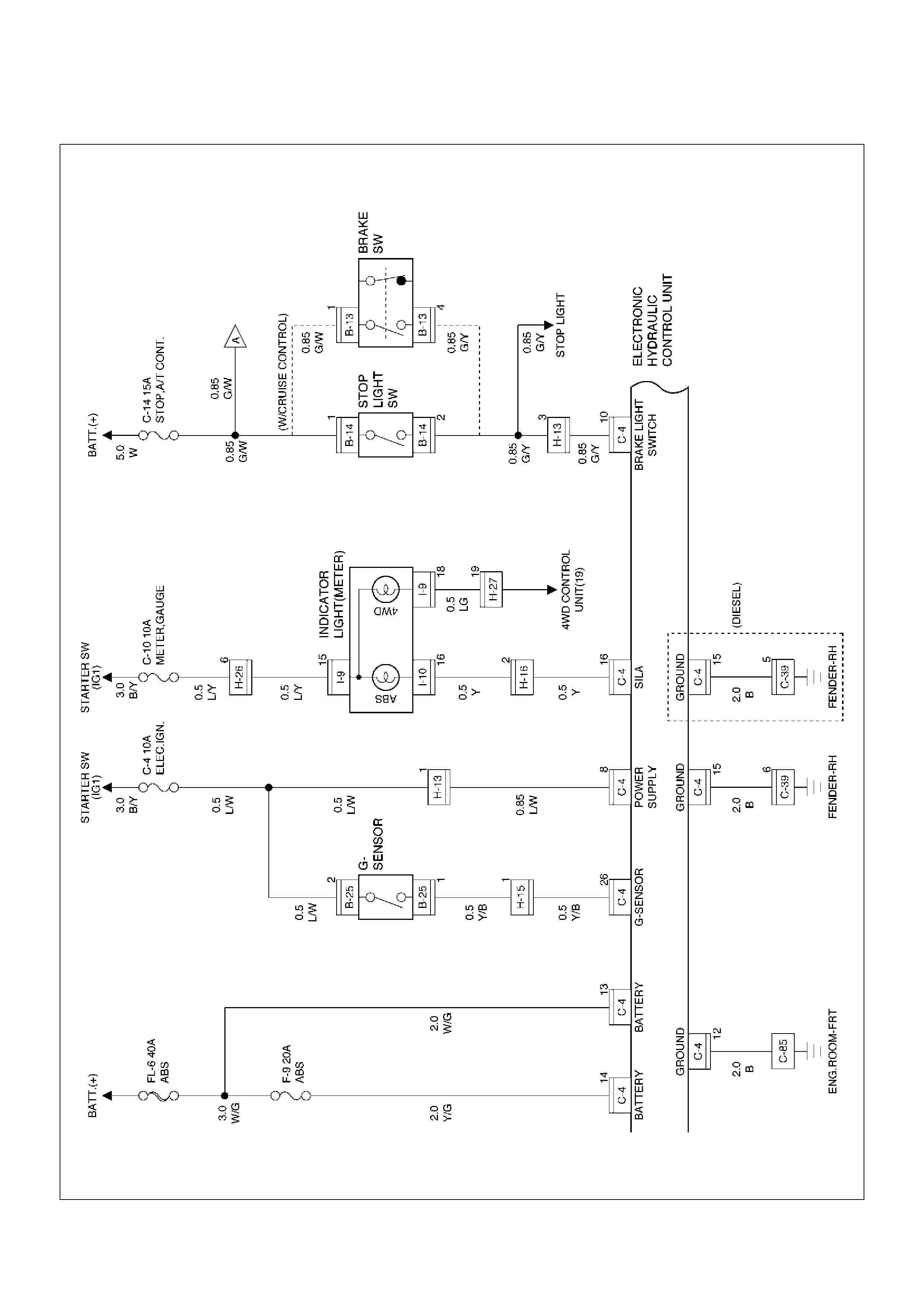
Circuit Diagram ( 6VE1 and 4JX1)
D08RW601
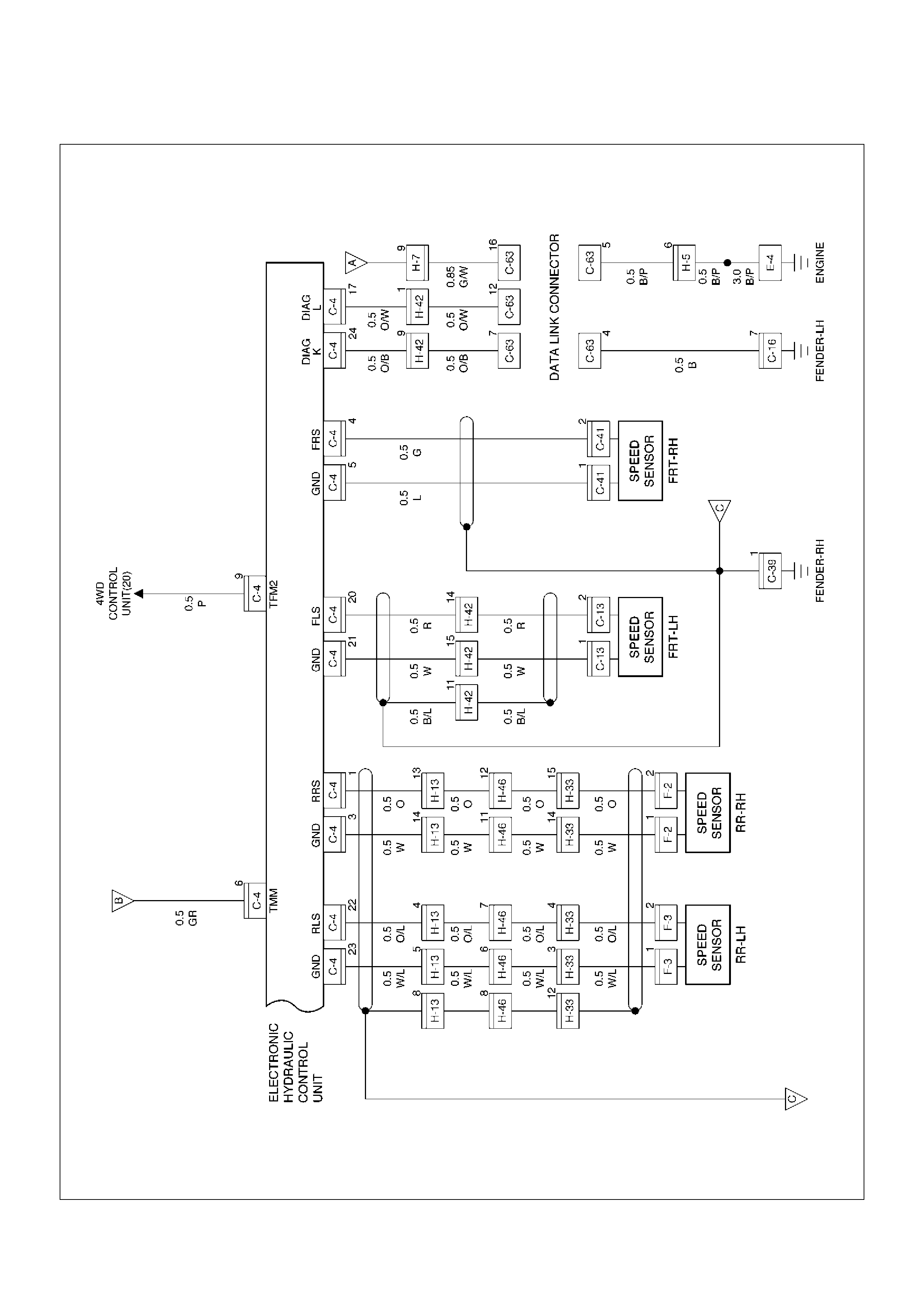
Circuit Diagram ( 4JX1)
D08RW600
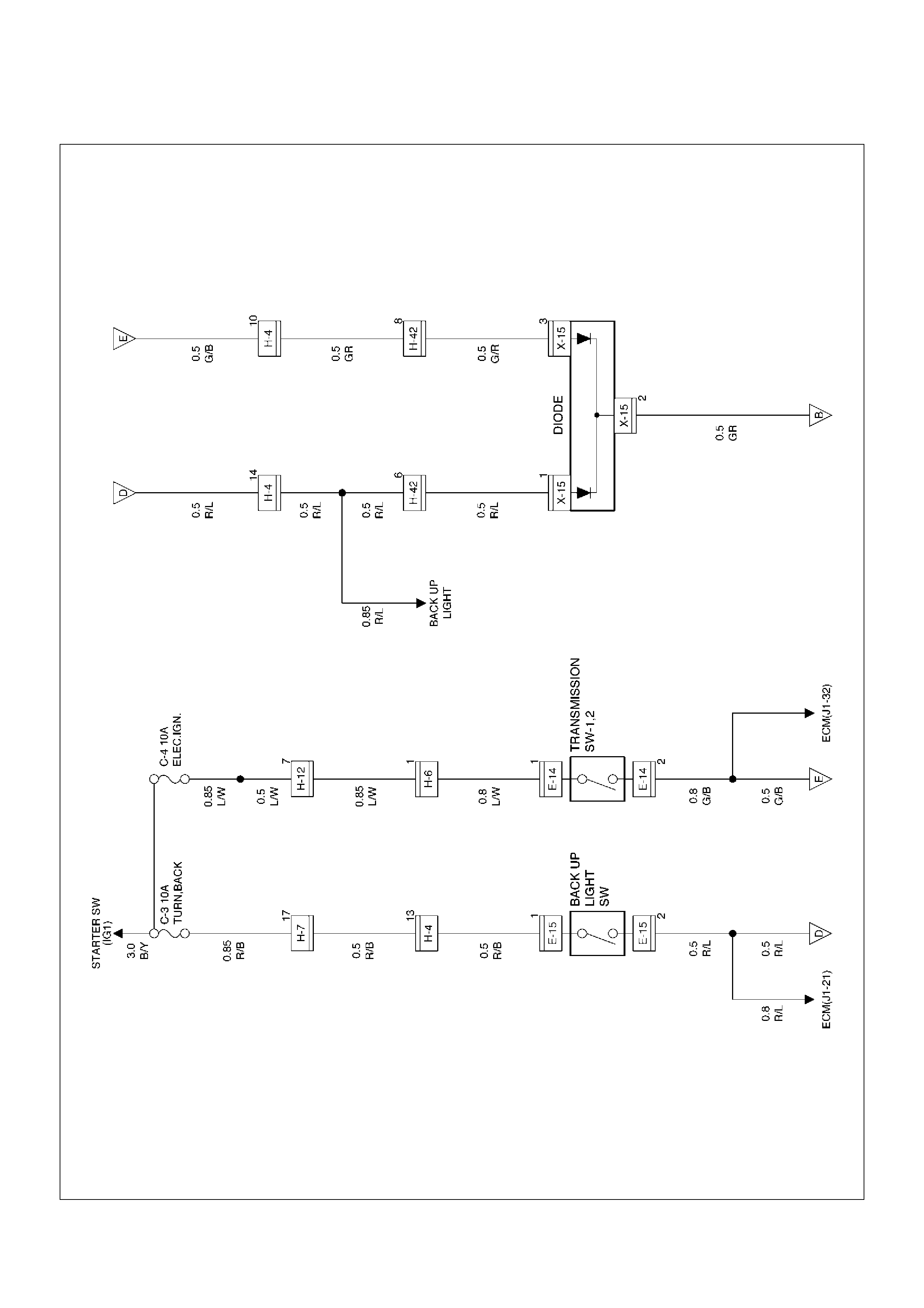
Circuit Diagram ( 4JX1)
D08RW602
Circuit Diagram ( 6VE1)
D08RW604
Circuit Diagram ( 6VE1)
D08RW603
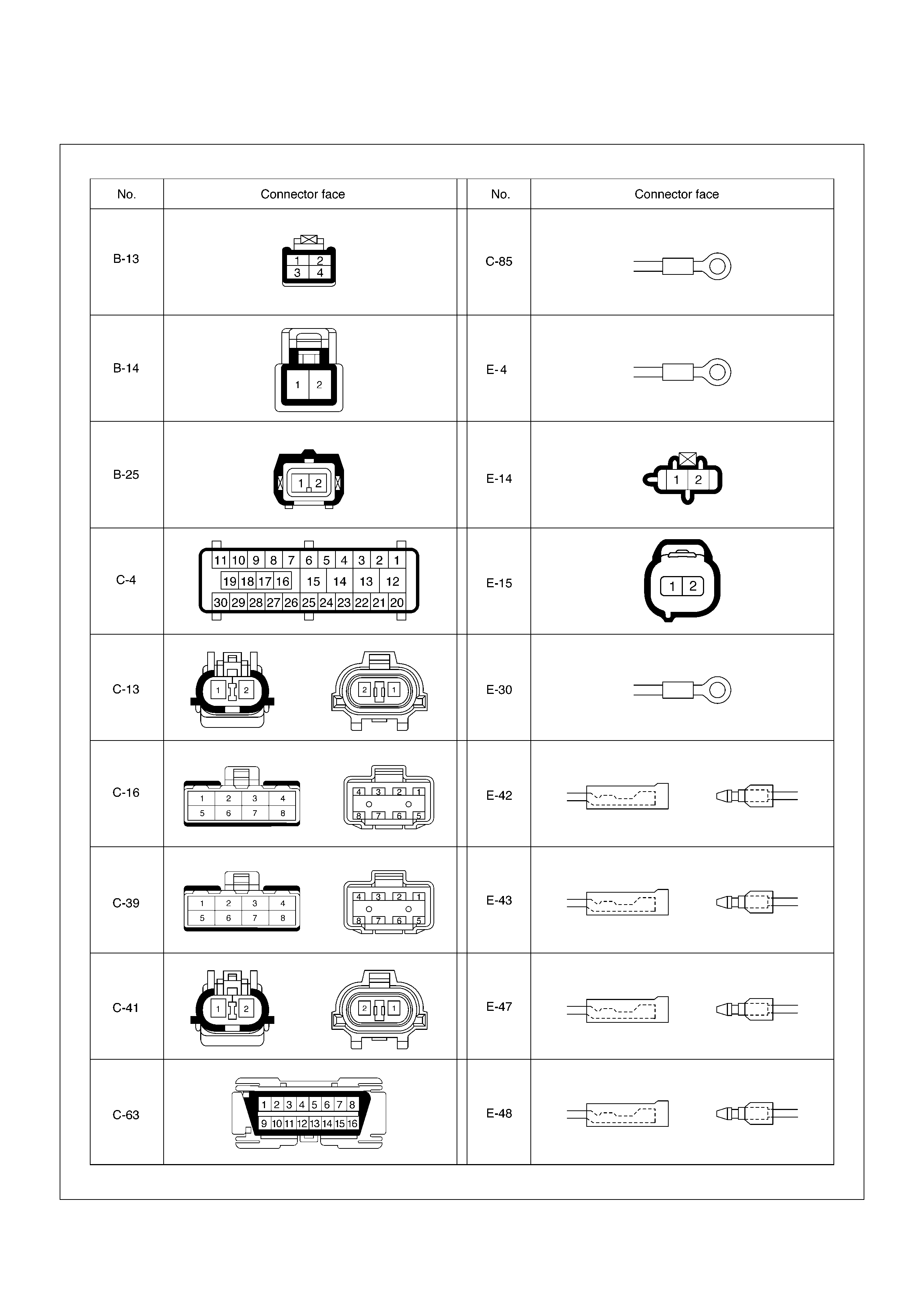
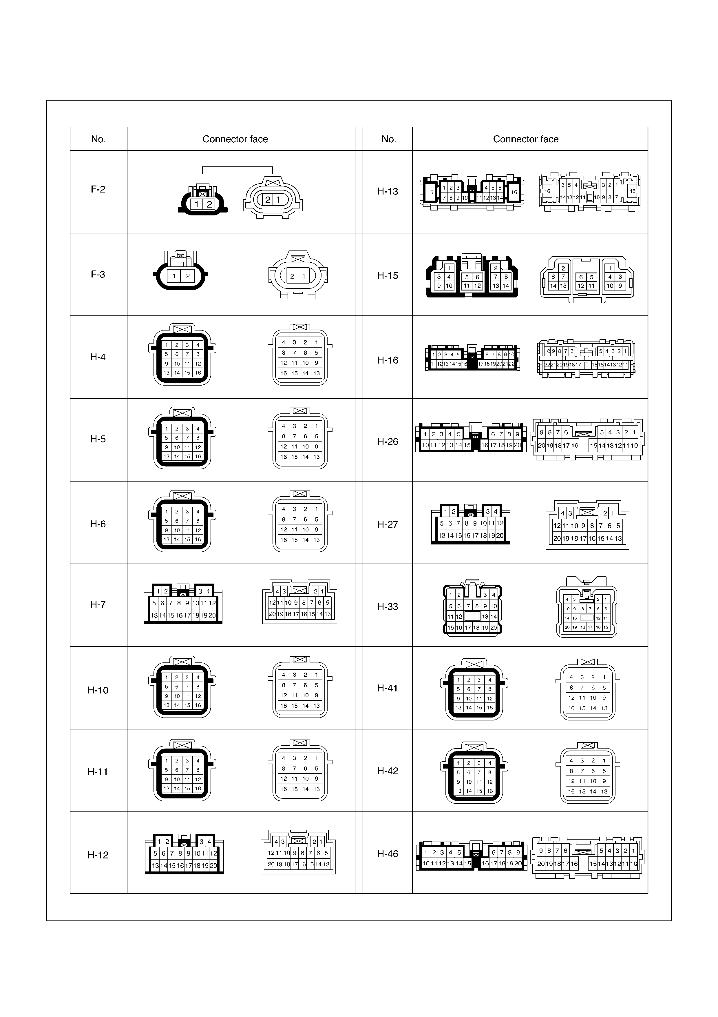
Connector List
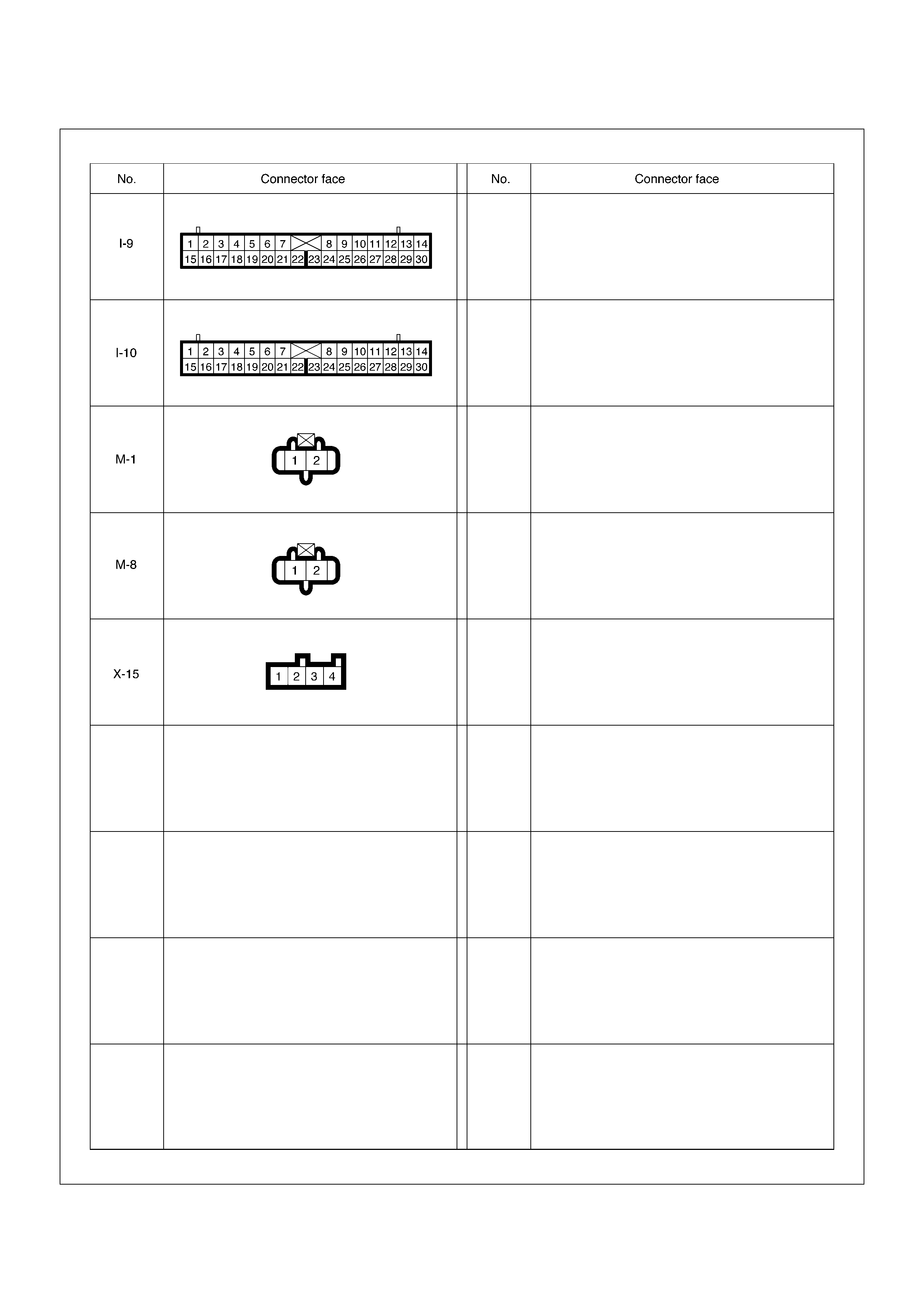
Part Location
D08RW623
EndOFCallout
Legend
(1) F–2
(2) F–3
(3) H–33
(4) H–7
(5) H–46
(6) C–16
(7) E–42, E–43, M–8
(8) E–47, E–48, M–1
(9) B–13 or B–14
(10) C–13
(11) H–4, H–5, H–6
(12) H–10, H–11
(13) E–4 (4JX1)
(14) E–30 (4GJ2, 6VD1/6VE1)
(15) Fuse Box
(16) H–42
(17) C–41
(18) C–85
(19) C–4 (EHCU)
(20) Relay & Fuse Box
(21) C–39
(22) H–13, H–15, H–16, H–26, H–27
(23) I–10
(24) I–9
(25) H–12
(26) C–63
(27) B–25

Symptom Diagnosis
The symptoms that cannot be indicated by the warning
light can be divided in the following five categories:
1. ABS works frequently but vehicle does not
decelerate.
2. Uneven braking occurs while ABS works.
3. The wheels lock during braking.
4. Brake pedal feel is abnormal.
5. Braking sound (from EHCU) is heard while not
braking.
These are all attributable to problems which cannot be
detected by EHCU self-diagnosis. Use the customer
complaint and a test to determine which symptom is
present. Then follow the appropriate flow chart listed
below.
Chart A–1 ABS Works Frequently But Vehicle Does Not Decelerate
No. Symptom Diagnostic Flow Charts
Without TECH 2 With TECH 2
1 ABS works frequently but vehicle does not decelerate. Chart A–1 Chart TA–1
2 Uneven braking occurs while ABS works. Chart A–2 —
3 The wheels are locked. Chart A–3 Chart TA–3
4 Abnormal Brake pedal ‘Feel’ Chart A–4 —
5 Braking sound (from EHCU) is heard while not braking. Chart A–5 Chart TA–5
Step Action Yes No
1 1. Turn key off.
2. G Sensor connector and EHCU connector disconnected.
Is there continuity between EHCU terminals 26 and 8? Go to Step 2 Go to Step 3
2 Connect EHCU connector.
Is there continuity between the G sensor and the EHCU? Go to Step 3
Repair circuit.
Go to Step 1
3 Is the G sensor normal? (Refer to chart B-5)
Go to Step 4
Replace G
sensor.
Go to Step 11
4 Is braking force distribution normal between the front and rear of
the vehicle?
Go to Step 5
Repair brake
parts.
Go to Step 11
5 Are axle parts installed normally?
Go to Step 6
Repair axle
parts.
Go to Step 11
6 Is there play in each wheel speed sensor? Repair wheel
speed sensor.
Go to Step 11 Go to Step 7
7 Is there damage, or powered iron sticking to each wheel speed
sensor/sensor ring?
Replace sensor
or sensor ring.
Go to Step 11 Go to Step 8
8 Is the output of each wheel speed sensor normal? (Refer to
chart C-1 or TC-1)
Go to Step 9
Replace wheel
speed sensor or
repair harness.
Go to Step 11
9 Is the input of transmission normal? (Refer to chart C-2 or TC-2)
Go to Step 10
Replace switch
or repair
harness.
Go to Step 11
10 Is the input of 4WD controller normal?
Go to Step 11
Replace
controller or
repair harness.
Go to Step 11

Chart TA-1 ABS Works Frequently But Vehicle Does Not Decelerate (Use TECH 2)
Chart A-2 Uneven Braking Occurs While ABS Works
Chart A-3, TA-3 The Wheels Are Locked
11 Reconnect all components and ensure all components are
properly mounted.
Was this step finished?
Repeat the “Basic
diagnostic flow
chart.” Go to Step 11
Step Action Yes No
Step Action Yes No
1 1. Connect TECH 2.
2. Make sure of the output conditions of each wheel speed
sensor by mode“F1: Data Display”.
Is the output of each sensor normal? Go to Step 2
Replace wheel
speed sensor.
Go to Step 3
2 Return to Chart A-1.
Was the Chart A-1 finished? Go to Step 3 Go to Step 2
3 Reconnect all components, ensure all components are properly
mounted.
Was this step finished?
Repeat the “Basic
diagnostic flow
chart.” Go to Step 3
Step Action Yes No
1 Is there any movement in each sensor? Repair.
Go to Step 5 Go to Step 2
2 Is there damage or powdered iron sticking to each sensor/sensor
ring?
Repair.
Go to Step 5 Go to Step 3
3 Is the output of each sensor normal? (Refer to chart C-1 or
TC-1)
Go to Step 4
Replace sensor
or repair
harness.
Go to Step 5
4 Are the brake hydraulic pipes connected correctly?
Replace EHCU.
Go to Step 5
Reconnect
brake pipe
correctly.
Go to Step 5
5 Reconnect all components, ensure all components are properly
mounted.
Was this step finished?
Repeat the “Basic
diagnostic flow
chart.” Go to Step 5
Step Action Yes No
1 Is ABS working? Go to Step 2 Go to Step 6
2 Is vehicle speed under 10 km/h (6mph)? Normal. Go to Step 3
3 Is sensor output normal? (Chart C-1 or TC-1)
Go to Step 4
Replace sensor
or repair
harness.
Go to Step 9
4 Is transmission input normal? (Chart C-2 or TC-2)
Go to Step 5
Replace SW or
repair harness.
Go to Step 9
5 Is front 4WD controller normal?
Replace EHCU.
Go to Step 9
Replace 4WD
controller or
repair harness.
Go to Step 9

Chart A-4 Abnormal Brake Pedal ‘Feel’
6 Is transmission input normal? (Chart C-2 or TC-2)
Go to Step 7
Replace SW or
repair harness
Go to Step 9
7 Is front 4WD controller normal?
Go to Step 8
Replace 4WD
controller or
repair harness.
Go to Step 9
8 Is hydraulic unit grounded properly? Replace EHCU.
Go to Step 9
Correct.
Go to Step 9
9 Reconnect all components, ensure all components are properly
mounted.
Was this step finished?
Repeat the “Basic
diagnostic flow
chart.” Go to Step 9
Step Action Yes No
Step Action Yes No
1 Is the stop light actuated when the brake pedal is depressed? Go to Step 2 Go to Step 3
2 1. Turn the ignition switch off.
2. Disconnected EHCU connector.
3. Measure voltage between the EHCU connector terminal 10
and 15 when brake pedal is depressed.
Is the voltage equal to the battery voltage? Go to Step 4
Harness NG
between brake
SW and EHCU.
Go to Step 7
3 Is stop light fuse C-14 normal?
Go to Step 5
Replace fuse
C-14.
Go to Step 7
4 Is there continuity between EHCU connector terminals, 12 and
15 to body ground?
Go to Step 6
Repair body
grounded
harness.
Go to Step 7
5 Is the brake SW funtioning correctly? Repair stop
light harness.
Go to Step 7
Replace brake
SW.
Go to Step 7
6 Does the harness or connector have an intermittent open circuit?
Repair harness
Go to step 7
Hydraulic
system leak or
air in the
system.
Refer to
Servicing
“Leakage or
brake fluid”
7 Reconnect all components and ensure all components are
properly mounted.
Was this step finished?
Repeat the “Basic
diagnostic flow
chart.” Go to Step 7

Chart A-5, TA-5 Braking Sound (From EHCU) Is Heard While Not Braking
Step Action Yes No
1 Is this the first time the vehicle is being driven after starting the
engine?
It is self
checking
sound.
Normal. Go to Step 2
2 Is vehicle speed under 10 km/h (6 mph)? It is self
checking
sound.
Normal. Go to Step 3
3 Check for the following condition:
• At the time of shift down or clutch operation.
• At the time of low m drive (ice or snow road) or rough road
drive.
• At the time of high-speed turn.
• At the time of passing curb.
• At the time of operating electrical equipment switches.
• At the time of racing the engine (over 5000 rpm).
Did it occur under any one condition above?
ABS may
sometime be
actuated even
when brake pedal
is not applied. Go to Step 4
4 Is there play in each sensor/wheel speed sensor rings?
Go to Step 5
Repair.
Go to Step 7
5 Damage or powdered iron sticking to each sensor/wheel speed
sensor ring? Go to Step 6
Repair.
Go to Step 7
6 Is each sensor output normal? (Refer to chart C-1 or TC-1). Check harness/
connector for
suspected
disconnection.
If no
disconnection is
found, replace
EHCU.
Go to Step 7
Repair.
Go to Step 7
7 Reconnect all components, ensure all components are properly
mounted.
Was this step finished?
Repeat the “Basic
diagnostic flow
chart.” Go to Step 7

Diagnostic Trouble Codes
Choose and trace an appropriate flowchart by the
numbers listed below to find fault and repair.
Code Item Diagnosis Chart No.
12 Start Code Normal —
14 EHCU Function Abnormality in input/output, operational and
control circuits
B-2
15 Power Voltage Drop B-3
16 CLASS–2 Communication Line
Abnormality
B-4
21 G-sensor Wiring disconnection B-5
23 Transmission Input Input abnormality B-6
24 Transfer Monitor B-7
32 Motor & Motor Relay Shorted or disconnected coil B-8
35 Valve Relay Shorted or disconnected coil/wiring B-9
41 FL Holding Solenoid Valve Shorted or disconnected coil/wiring B-10
42 FL Decompression Solenoid Valve Shorted or disconnected coil/wiring B-11
43 FR Holding Solenoid Valve Shorted or disconnected coil/wiring B-12
44 FR Decompression Solenoid Valve Shorted or disconnected coil/wiring B-13
45 Rear Holding Solenoid Valve Shorted or disconnected coil/wiring B-14
46 Rear Decompression Solenoid Valve Shorted or disconnected coil/wiring B-15
51 FL Wheel Speed Sensor Disconnected coil/wiring B-16
52 FR Wheel Speed Sensor Disconnected coil/wiring B-17
53 RL Wheel Speed Sensor Disconnected coil/wiring B-18
54 RR Wheel Speed Sensor Disconnected coil/wiring B-19
61 FL Wheel Speed Sensor Shorted coil/wiring B-20
62 FR Wheel Speed Sensor Shorted coil/wiring B-21
63 RL Wheel Speed Sensor Shorted coil/wiring B-22
64 RR Wheel Speed Sensor Shorted coil/wiring B-23
65 Sensor Signal Input Wrong number of teeth B-24
Diagnosis By “ABS” Warning
Light Illumination Pattern
In the event that there is abnormality in the “ABS”
warning light illumination pattern while the key is in the
ON position or if the warning light is actuated during
driving, trouble should be diagnosed on a illumination
pattern basis as follows:
Diagnostic Trouble Codes (DTCs)
When the warning light in the meter remains ON, the
EHCU stores the fault identification and disables the
ABS.
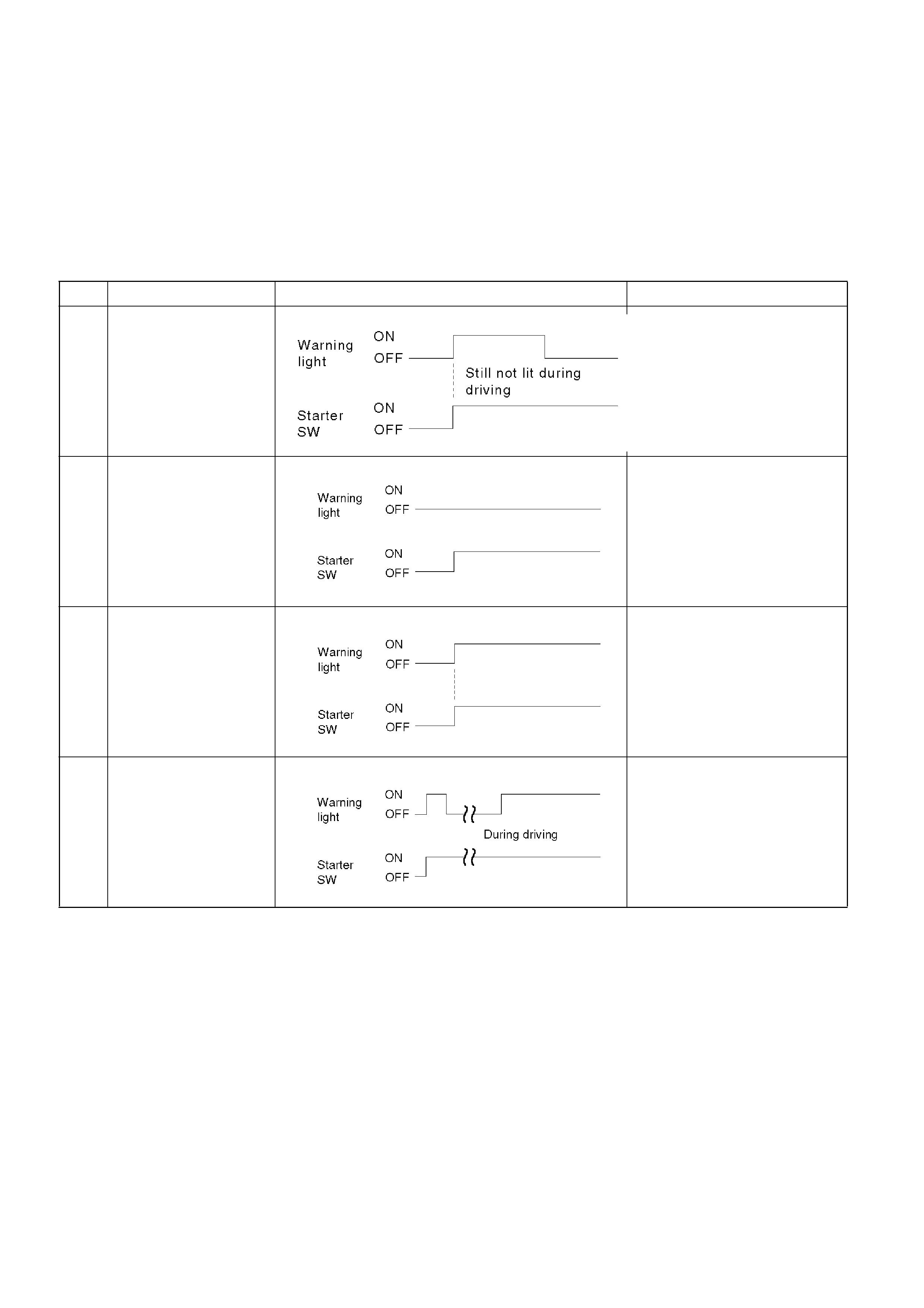
1. How to display and erase DTCs:
NOTE:
• If DTCs are not displayed, harness C-4 connector
terminal 30 and I-10 connector terminal 2 may be
disconnected. Repair the harness and try DTC
display again.
• DTCs can be displayed also by TECH 2. Select
mode “F0: Diagnostic Trouble Codes” from
Application Menu.
1. How to start DTC display:
• Confirm that the vehicle has come to a complete
stop (with the wheels standing still) and that the
brake pedal is not depressed. (Unless these two
conditions are satisfied, DTC display cannot be
started.)
• With IGN OFF, connect #12 terminal with #4
terminal or # 5 terminal (GND) . Then turn IGN
ON.
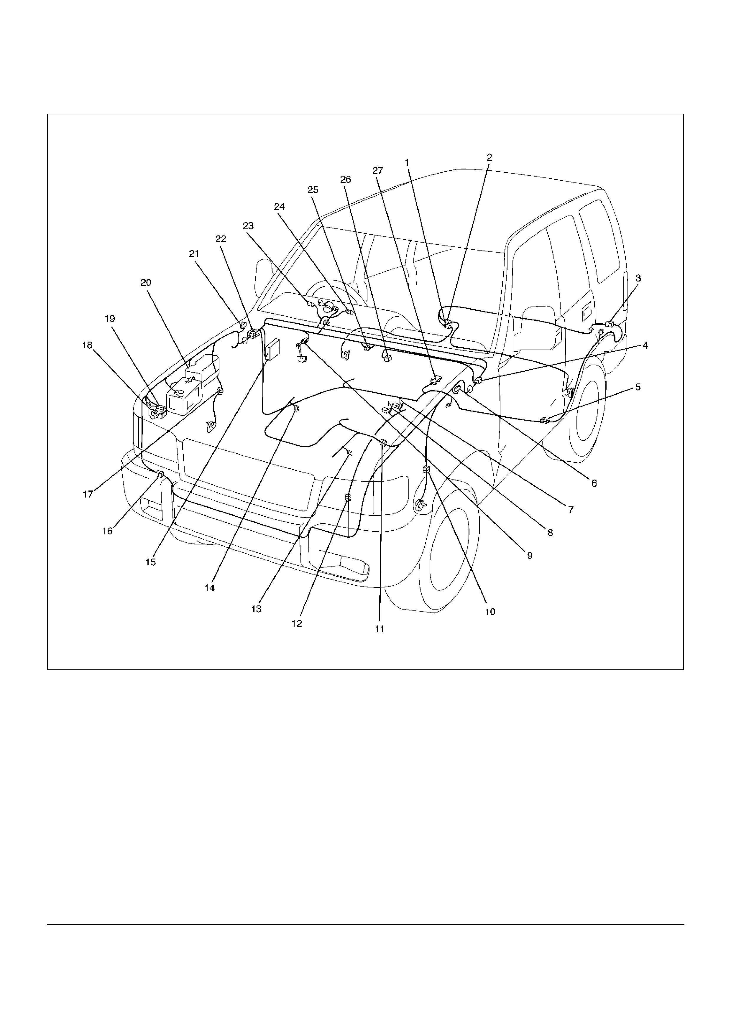
No. Condition “ABS” Warning Light Illumination Pattern Diagnostic
1 Warning light is
actuated normally
Normal
2 Warning light is not lit Warning light lighting circuit
trouble®Go to Chart B-1
3 Warning light remains
ON
Diagnostic trouble codes are
stored.
Display diagnostic trouble
codes and diagnose on a
code basis according to the
flow charts.
4 Warning light is
actuated while driving
Diagnostic trouble codes are
stored.
Display diagnostic trouble
codes and diagnose on a
code basis according to the
flow charts.
The DLC is located behind the center console
350RV010
• Keep #12 terminal connected with #4 terminal or
# 5 terminal (GND) during DTC display. (If #12
terminal is separated from #4 terminal or # 5
terminal (GND) during display, display will stop.)
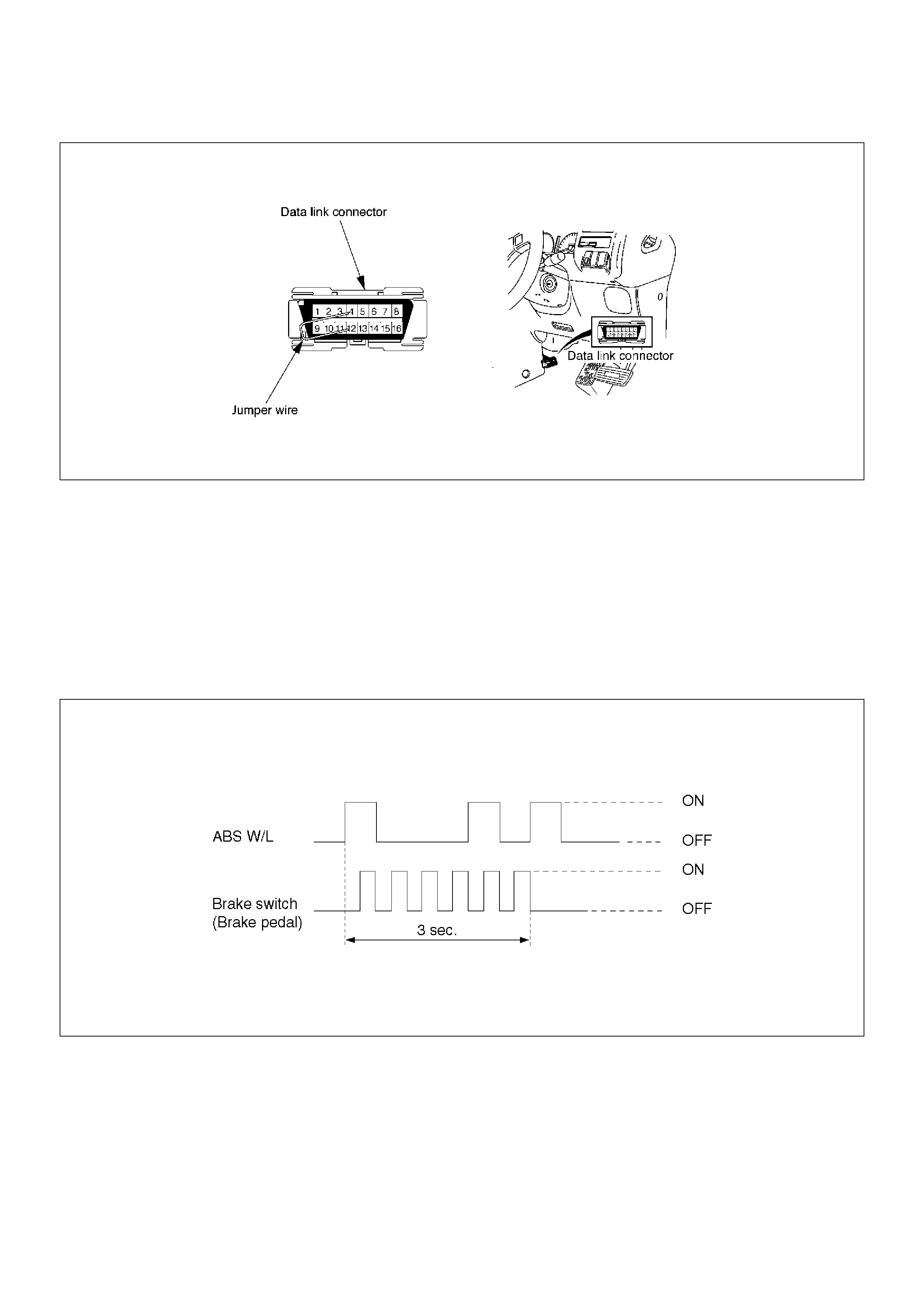
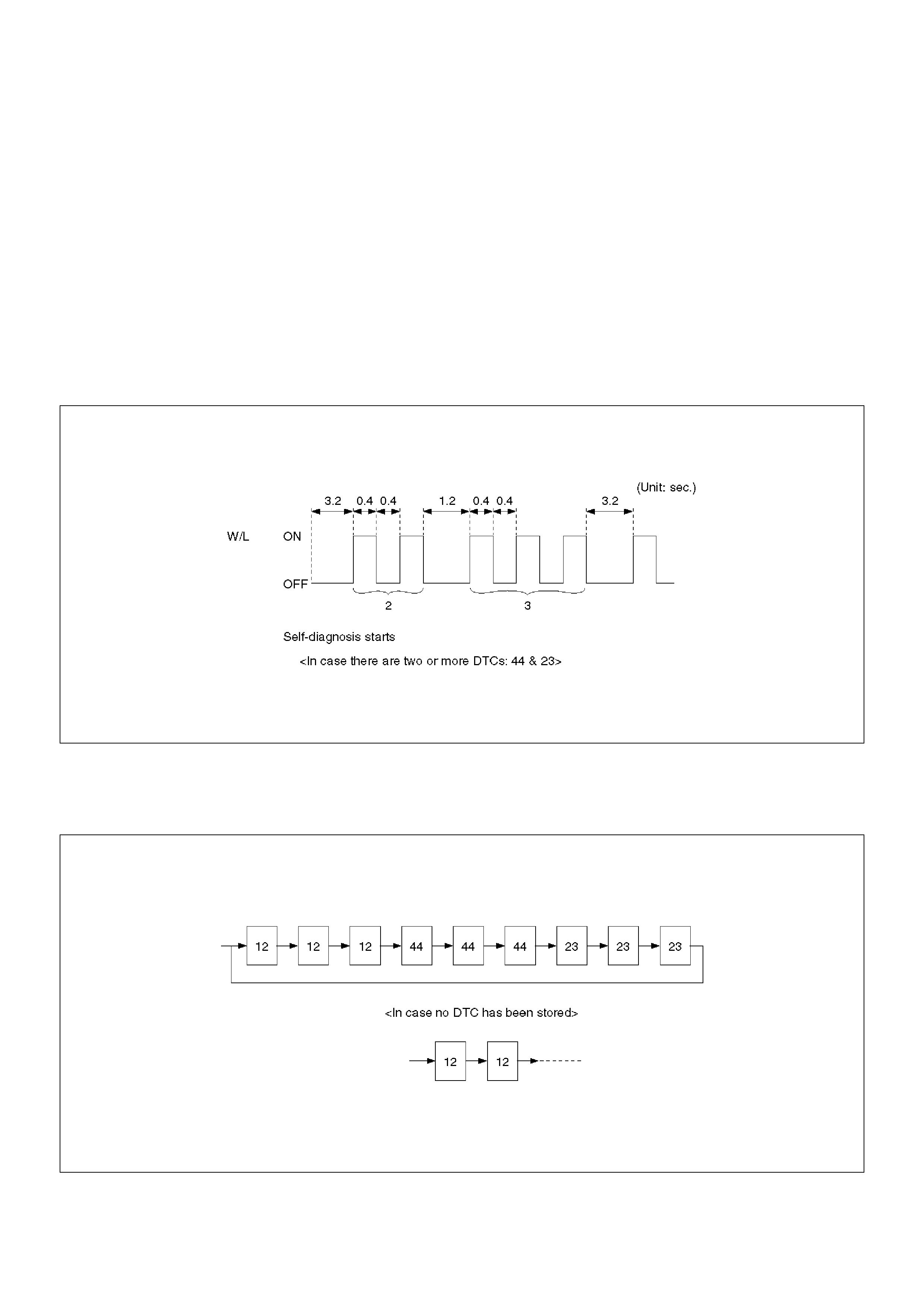
2. DTC display:
• DTC is displayed by blinking warning light.
• Double-digit display.
• First, normal DTC 12 is displayed three times and
then any other DTCs are displayed three times.
(If no other DTCs have been stored, the display
of DTC 12 will be repeated.)
3. How to erase code:
• Conduct brake switch ON/OFF operation 6 or
more times within 3 seconds of self-diagnosis
startup.
• The code cannot be erased if more than 3
seconds have passed since self-diagnosis
startup, or if self-diagnosis has started with brake
switched on (brake pedal depressed).
B05RW005
4. Notes
• If the following should occurs during Diagnostic
Trouble Code (DTC) display the display will be
discontinued. After initial check, the status that is
under the control of ABS will be returned :
– The vehicle starts (The wheels turn) or the
brake pedal is depressed.
• Up to 3 different codes can be stored.
• If the ABS should turn OFF due to an intermittent
defect, the system will be restored at the next key
cycle, if the initial check finds no abnormality
(when IGN is switched from OFF to ON).
5. An example of DTC display
Display of DTC 23
B05RW006
After displaying DTC 12 three times, one DTC after
another is displayed, starting with the most recent
one. (However, display is discontinued after about 5
minutes.)
B05RS005
The DTC 12 is displayed repeatedly. (display is
discontinued after about 5 minutes)

Chart B-1 With the key in the ON position (Before starting the engine). Warning light (W/L)
is not activated.
Chart B-2 EHCU Abnormality (DTC 14)
Step Action Yes No
1 Is W/L fuse C-10 disconnected? Replace fuse.
Go to Step 5 Go to Step 2
2 Is W/L burnt out? Replace W/L
bulb.
Go to Step 5 Go to Step 3
3 1. Turn the key off.
2. Disconnect EHCU connector.
3. Turn the key ON.
4. Measure the voltage between EHCU connector terminal 13
and 14.
Is the voltage equal to the battery voltage? Go to Step 4
Repair harness
and connector.
Go to Step 5
4 Is there continuity between EHCU connector terminals, 12 and
15 and body ground.
Check harness
for suspected
disconnection.
No fault found:
Replace EHCU.
Go to Step 5
Repair harness
and connector.
Go to Step 5
5 Reconnect all components, ensure all components are properly
mounted.
Was this step finished?
Repeat the “Basic
diagnostic flow
chart.” Go to Step 5
Step Action Yes No
1 1. Turn the key off.
2. Disconnect the EHCU connector.
3. Inspect EHCU ground.
Is there resistance between the EHCU connector terminals, 12
and 15 and body ground? Go to Step 2
Repair the body
ground
harness.
Go to Step 3
2 1. Turn the key off, connect the EHCU.
2. Erase the trouble code.
3. Turn Ignition off, then on, to perform system self-check.
4. If warning light remains on, display trouble codes once again.
Is the check trouble code 14?
Replace EHCU.
Go to Step 3
Inspect in
accordance with
the DTC displayed.
3 1. Reconnect all components and ensure all components are
properly mounted.
2. Clear diagnostic trouble code.
Was this step finished?
Repeat the “Basic
diagnostic flow
chart.” Go to Step 3

Chart B-3 Power Voltage Drop (DTC 15)
Chart B-4 CLASS-2 Communication Line Abnormality (DTC 16)
Step Action Yes No
1 Is the battery voltage normal? (Battery capacity check)
Go to Step 2
Charge or
replace battery.
Go to Step 2
2 1. Turn the key off.
2. Disconnect EHCU connector.
3. Turn the key on.
Is the voltage between EHCU connector terminals 8 and 15,
higher than 10V?
Check harness
connector for
suspected
disconnection.
Fault found:
Repair, and
perform system
self-check.
No fault found:
replace EHCU.
Go to Step 3
Repair harness
or connector.
Go to Step 3
3 1. Reconnect all components, ensure all components are
properly mounted.
2. Clear diagnostic trouble code.
Was this step finished?
Repeat the “Basic
diagnostic flow
chart.” Go to Step 3
Step Action Yes No
1 1. Turn the key off.
2. Disconnect EHCU and PCM connector.
Is there continuity between EHCU connector terminals 25 and
ground? Go to Step 2
Repair harness
or connector.
Go to Step 3
2 1. Connect EHCU connector.
2. Clear diagnostic trouble code.
3. Turn the key on.
Is the diagnostic trouble code 16 shown on the displayed?
Check the PCM
harness. Refer
to 6E section.
Go to Step 3
Replace EHCU.
Go to Step 3
3 1. Reconnect all components, ensure all components are
properly mounted.
2. Clear diagnostic trouble code.
Was this step finished?
Repeat the “Basic
diagnostic flow
chart.” Go to Step 3

Chart B-5 G-Sensor Circuit (DTC 21)
Step Action Yes No
1 Vehicle placed horizontal.
Is the resistance between the G sensor connector terminals 1
and 2 within 4.0-6.0 kW?
Check harness
connector for
short.
Fault found :
Repair , and
perform system
self-check.
No fault found :
replace EHCU.
Go to Step 3 Go to Step 2
2 Is the bracket installed horizontally?
Go to Step 4
Repair or
replace bracket.
Go to Step 4
3 Remove G sensor.
Is the resistance between the G sensor connector terminals 1
and 2 within 1.0-2.0 kW when G sensor is horizontal? Go to Step 4
Replace G
sensor.
Go to Step 5
4 Measure resistance between G sensor connector terminals 1 and
2 within 4.0-6.0 kW when G sensor tilted to 30° or more?
Harness
between EHCU
and G sensor is
faulty and short.
Repair the
harness
Go to Step 5
Replace G
sensor.
Go to Step 5
5 1. Reconnect all components and ensure all components are
properly mounted.
2. Clear diagnostic trouble code.
Was this step finished?
Repeat the “Basic
diagnostic flow
chart.” Go to Step 5

Chart B-6 Abnormal Transmission Input (DTC 23)
Step Action Yes No
1 1. Turn the key off.
2. Disconnect EHCU connector.
Is there continuity between EHCU connector terminal 6 to 15
(Gear position-P(A/T), N(M/T))?
Shorted switch
harness.
Repair switch or
harness.
Go to Step 6 Go to Step 2
2 Is the vehicle an A/T model? Go to Step 3 Go to Step 4
3 Turn the key on and measure the voltage between EHCU
connector terminal 6 and 15.
Is the 6V under when the gear position is L, and R(Battery
voltage 12V)?
Go to Step 5
Transmission
SW trouble.
Disconnected
harness.
Repair SW and
harness.
Go to Step 6
4 Turn the key on and measure the voltage between EHCU
connector terminal 6 and 15.
Is the 9.6V over when the gear position is 1, 2, R(Battery voltage
12V)?
Go to Step 5
Transmission
SW trouble.
Disconnected
harness.
Repair SW and
harness.
Go to Step 6
5 Is there 6.6 to 9.0V when the gear position is 3, 4, 5 and N(M/T)
or 2,3,D,N and P(A/T)(Battery voltage 12V)?
Suspected
harness/
connector short
power source/
GND.
Suspected
shorted
transmission
SW.
Fault found:
repair, and
perform system
self-check.
No fault found:
replace EHCU.
Go to Step 6
Transmission
SW trouble.
Disconnected
harness.
Repair SW and
harness.
Go to Step 6
6 1. Reconnect all components, ensure all components are
properly mounted.
2. Clear diagnostic trouble code.
Was this step finished?
Repeat the “Basic
diagnostic flow
chart.” Go to Step 6

Chart B-7 Transfer Monitor (DTC 24)
Chart B-8 EHCU Pump Motor And Motor Relay Circuit (DTC 32)
Chart B-9 EHCU Pump Valve And Valve Relay Circuit (DTC 35)
Step Action Yes No
1 1. Turn the key off.
2. Disconnect EHCU connector.
Is the EHCU connector terminal 9 line normally? Go to Step 2
Repair
Go to Step 3
2 Is the TOD ECU or 4WD controller normal?
Replace EHCU.
Go to Step 3
Repair or
replace TOD
ECU or 4WD
contrder.
Go to Step 3
3 1. Reconnect all components, ensure all components are
properly mounted.
2. Clear diagnostic trouble code.
Was this step finished?
Repeat the “Basic
diagnostic flow
chart.” Go to Step 3
Step Action Yes No
1 1. Turn the key off.
2. Disconnect EHCU connector.
3. Measure voltage between EHCU connector terminal 13 and
body ground.
Is the voltage equal to battery voltage?
Go to Step 2
Repair fuse/
harness
between battery
and EHCU
connector
terminal 13.
Go to Step 3
2 Is there continuity between EHCU connector terminal 12 and
ground?
Go to Step 3
Repair between
EHCU
connector
terminal 12 and
ground.
Go to Step 3
3 1. Reconnect all components and ensure all components are
properly mounted.
2. Clear diagnostic trouble code.
Was this step finished?
Repeat the “Basic
diagnostic flow
chart.” Go to Step 3
Step Action Yes No
1 1. Turn the key off.
2. Disconnect EHCU connector.
3. Measure voltage between EHCU connector terminal 14 and
body ground.
Is the voltage equal to battery voltage? Replace EHCU.
Go to Step 2
Repair fuse and
harness EHCU
connector
terminal 14 and
battery.
Go to Step 2
2 1. Reconnect all components and ensure all components are
properly mounted.
2. Clear diagnostic trouble code.
Was this step finished?
Repeat the “Basic
diagnostic flow
chart.” Go to Step 2

Chart B-10 FL Isolation Solenoid Valve Abnormality (DTC 41)
Chart B-11 FL Dump Solenoid Valve Abnormality (DTC 42)
Chart B-12 FR Isolation Solenoid Valve Abnormality (DTC 43)
Step Action Yes No
1 Was the “EHCU Connector Pin-out Checks” performed?
Go to Step 2
Go to“EHCU
Connector Pin-out
Checks”.
2 Is the EHCU connector free from damage or corrosion?
Go to Step 3
Repair the
connector.
Repeat
the“Basic
Diagnostic Flow
Chart”.
3 1. Replace the EHCU.
2. Reconnect all component, ensure all component are properly
mounted.
Was this step finished?
Repeat the“Basic
Diagnostic Flow
Chart”. Go to Step 3

Chart B-13 FR Dump Solenoid Valve Abnormality (DTC 44)
Chart B-14 Rear Isolation Solenoid Valve Abnormality (DTC 45)
Chart B-15 Rear Dump Solenoid Valve Abnormality (DTC 46)
Step Action Yes No
1 Was the “EHCU Connector Pin-out Checks” performed?
Go to Step 2
Go to“EHCU
Connector Pin-out
Checks”.
2 Is the EHCU connector free from damage or corrosion?
Go to Step 3
Repair the
connector.
Repeat
the“Basic
Diagnostic Flow
Chart”.
3 1. Replace the EHCU.
2. Reconnect all component, ensure all component are properly
mounted.
Was this step finished?
Repeat the“Basic
Diagnostic Flow
Chart”. Go to Step 3

Chart B-16 FL Speed Sensor Disconnection (DTC 51)
Chart B-17 FR Speed Sensor Disconnection (DTC 52)
Step Action Yes No
1 1. Turn the key off.
2. Disconnect EHCU connector.
3. Measure the resistance between EHCU connector terminals
20 and 21.
Is the resistance between 1.3k and 1.9k ohms?
Check for faults
in harness
between speed
sensor and
EHCU.
Fault found:
Repair, and
perform system
self-check.
No fault found:
Replace EHCU.
Go to Step 3 Go to Step 2
2 Measure the FL speed sensor resistance at the sensor
connector.
Is the resistance between 1.3k and 1.9k ohms?
Repair harness
abnormality
between
sensors and
EHCU.
Go to Step 3
Replace
sensor.
Go to Step 3
3 1. Reconnect all components, ensure all components are
properly mounted.
2. Clear diagnostic trouble code.
Was this step finished?
Repeat the “Basic
diagnostic flow
chart.” Go to Step 3
Step Action Yes No
1 1. Turn the key off.
2. Disconnect EHCU connector.
3. Measure the resistance between EHCU connector terminals
4 and 5.
Is the resistance between 1.3k and 1.9k ohms?
Check for faults
in harness
between speed
sensor and
EHCU.
Fault found:
Repair, and
perform system
self-check.
No fault found:
Replace EHCU.
Go to Step 3 Go to Step 2
2 Measure the FR speed sensor resistance at the sensor
connector.
Is the resistance between 1.3k and 1.9k ohms?
Repair harness
abnormality
between
sensors and
EHCU.
Go to Step 3
Replace
sensor.
Go to Step 3
3 1. Reconnect all components and ensure all components are
properly mounted.
2. Clear diagnostic trouble code.
Was this step finished?
Repeat the “Basic
diagnostic flow
chart.” Go to Step 3

Chart B-18 RL Speed Sensor Disconnection (DTC 53)
Chart B-19 RR Speed Sensor Disconnection (DTC 54)
Step Action Yes No
1 1. Turn the key off.
2. Disconnect EHCU connector.
3. Measure the resistance between EHCU connector terminals
22 and 23.
Is the resistance between 1.3k and 1.9k ohms?
Check for faults
in harness
between speed
sensor and
EHCU.
Fault found:
Repair, and
perform system
self-check.
No fault found:
Replace EHCU.
Go to Step 3 Go to Step 2
2 Measure the RL speed sensor resistance at the sensor
connector.
Is the resistance between 1.3k and 1.9k ohms?
Repair harness
abnormality
between
sensors and
EHCU.
Go to Step 3
Replace
sensor.
Go to Step 3
3 1. Reconnect all components and ensure all components are
properly mounted.
2. Clear diagnostic trouble code.
Was this step finished?
Repeat the “Basic
diagnostic flow
chart.” Go to Step 3
Step Action Yes No
1 1. Turn the key off.
2. Disconnect EHCU connector.
3. Measure the resistance between EHCU connector terminals
2 and 3.
Is the resistance between 1.3K and 1.9k ohms?
Check for faults
in harness
between speed
sensor and
EHCU.
Fault found:
Repair, and
perform system
self-check.
No fault found:
Replace EHCU.
Go to Step 3. Go to Step 2
2 Measure the RR speed sensor resistance at the sensor
connector.
Is the sensor resistance between 1.3k and 1.9k ohms?
Repair harness
abnormality
between
sensors and
EHCU.
Go to Step 3
Replace
sensor.
Go to Step 3
3 1. Reconnect all components and ensure all components are
properly mounted.
2. Clear diagnostic trouble code.
Was this step finished?
Repeat the “Basic
diagnostic flow
chart.” Go to Step 3

Chart B-20 FL Speed Sensor Short Circuit (DTC 61)
NOTE: Even after repairing the faulty part the warning
light (W/L) does not go out if the vehicle is at a stop.
Turn the ignition switch to the ON position and drive the
vehicle at 12 km/h or higher to make sure that the
warning light goes out.
Step Action Yes No
1 1. Turn the key off.
2. Disconnect EHCU connector
3. Measure the FL speed sensor resistance between EHCU
connector terminals 20 and 21.
Is the resistance between 1.3k and 1.9k ohms? Go to Step 2 Go to Step 3
2 Is there play in the sensor/sensor rotor?
Go to Step 4
Repair.
Go to Step 6
3 Measure the FL speed sensor resistance at the sensor
connector.
Is the resistance between 1.3k and 1.9k ohms?
Repair harness
abnormality
between
sensors and
EHCU.
Go to Step 6
Replace
sensor.
Go to Step 6
4 Damage and powdered iron sticking to sensor/sensor ring?
Go to Step 5
Repair.
Go to Step 6
5 Is sensor output normal? (Chart C-1-1 or TC-1) Check for faults
in harness
between speed
sensor and
EHCU.
Fault found:
repair, and
perform system
self-check.
No fault found:
replace EHCU.
Go to Step 6
Replace
sensor.
Go to Step 6
6 1. Reconnect all components and ensure all components are
properly mounted.
2. Clear diagnostic trouble code.
Was this step finished?
Repeat the “Basic
diagnostic flow
chart.” Go to Step 6

Chart B-21 FR Speed Sensor Short Circuit (DTC 62)
NOTE: Even after repairing the faulty part the warning
light (W/L) does not go out if the vehicle is at a stop.
Turn the ignition switch to the ON position and drive the
vehicle at 12 km/h or higher to make sure that the
warning light goes out.
Step Action Yes No
1 1. Turn the key off.
2. Disconnect EHCU connector.
3. Measure the FR speed sensor resistance between EHCU
connector terminals 4 and 5.
Is the resistance between 1.3k and 1.9k ohms? Go to Step 2 Go to Step 3
2 Is there play in the sensor/sensor rotor?
Go to Step 4
Repair.
Go to Step 6
3 Measure the FR speed sensor resistance at the sensor
connector.
Is the resistance between 1.3k and 1.9k ohms?
Repair harness
abnormality
between
sensors and
EHCU.
Go to Step 6
Replace
sensor.
Go to Step 6
4 Damage and powdered iron sticking to sensor/sensor ring?
Go to Step 5
Repair.
Go to Step 6
5 Is sensor output normal? (Chart C-1-2 or TC-1) Check for faults
in harness
between speed
sensor and
EHCU.
Fault found:
repair, and
perform system
self-check.
No fault found:
replace EHCU.
Go to Step 6
Replace
sensor.
Go to Step 6
6 1. Reconnect all components and ensure all components are
properly mounted.
2. Clear diagnostic trouble code.
Was this step finished?
Repeat “Basic
diagnostic flow
chart.” Go to Step 6

Chart B-22 RL Speed Sensor Short Circuit (DTC 63)
NOTE: Even after repairing the faulty part the warning
light (W/L) does not go out if the vehicle is at a stop.
Turn the ignition switch to the ON position and drive the
vehicle at 12 km/h or higher to make sure that the
warning light goes out.
Step Action Yes No
1 1. Turn the key off.
2. Disconnect EHCU connector
3. Measure the RL speed sensor resistance between EHCU
connector terminals 22 and 23.
Is the resistance between 1.3k and 1.9k ohms? Go to Step 2 Go to Step 3
2 Is there play in the sensor/sensor rotor?
Go to Step 4
Repair.
Go to Step 6
3 Measure the RL speed sensor resistance at the sensor
connector.
Is the resistance between 1.3k and 1.9k ohms?
Repair harness
abnormality
between
sensors and
EHCU.
Go to Step 6
Replace
sensor.
Go to Step 6
4 Damage and powdered iron sticking to sensor/sensor ring?
Go to Step 5
Repair.
Go to Step 6
5 Is sensor output normal? (Chart C-1-3 or TC-1)? Check for faults
in harness
between speed
sensor and
EHCU.
Fault found:
repair, and
perform system
self-check.
No fault found:
replace EHCU.
Go to Step 6
Replace
sensor.
Go to Step 6
6 1. Reconnect all components and ensure all components are
properly mounted.
2. Clear diagnostic trouble code.
Was this step finished?
Repeat the “Basic
diagnostic flow
chart.” Go to Step 6

Chart B-23 RR Speed Sensor Short Circuit (DTC 64)
NOTE: Even after repairing the faulty part the warning
light (W/L) does not go out if the vehicle is at a stop.
Turn the ignition switch to the ON position and drive the
vehicle at 12 km/h or higher to make sure that the
warning light goes out.
Step Action Yes No
1 1. Turn the key off.
2. Disconnect EHCU connector.
3. Measure the RR speed sensor resistance between EHCU
connector terminals 2 and 3.
Is the resistance between 1.3k and 1.9k ohms? Go to Step 2 Go to Step 3
2 Is there play in the sensor/sensor rotor?
Go to Step 4
Repair.
Go to Step 6
3 Measure the RR speed sensor resistance at the sensor
connector.
Is the resistance between 1.3k and 1.9k ohms?
Repair harness
abnormality
between
sensors and
EHCU.
Go to Step 6
Replace
sensor.
Go to Step 6
4 Damage and powdered iron sticking to sensor/sensor ring?
Go to Step 5
Repair.
Go to Step 6
5 Is sensor output normal? (Chart C-1-4 or TC-1) Check for faults
in harness
between speed
sensor and
EHCU.
Fault found:
repair, and
perform system
self-check.
No fault found:
replace EHCU.
Go to Step 6
Replace
sensor.
Go to Step 6
6 1. Reconnect all components and ensure all components are
properly mounted.
2. Clear diagnostic trouble code.
Was this step finished?
Repeat “Basic
diagnostic flow
chart.” Go to Step 6

Chart B-24 Sensor Signal Input Abnormality (DTC 65)
Sensor Signal Abnormality Criteria using
TECH 2
1. While driving, the speed of one or two wheels 25%
or more higher than that of the other wheels.
2. The speed of one or two wheels is 10 km/h (6 mph)
or more higher than that of the other wheels.
3. During steady driving, wheel speed changes
abruptly.
*1 The vehicle must run on a level paved road.
NOTE: Even after repairing the faulty part the warning
light (W/L) does not go out if the vehicle is at a stop.
Turn the ignition switch to the ON position and drive the
vehicle at 12 km/h or higher to make sure that the
warning light goes out.
It is important to verify that the correct tires are installed
on vehicle.
Step Action Yes No
1 Using TECH 2? Go to Step 2 Go to Step 3
2 1. Connect TECH 2.
2. Select Snap shot manual trigger.
3. With wheel speed data displayed, run the vehicle when
speed has arrived at 30 km/h (18 mph).
4. Check speed data on each wheel (refer to the criterion given
below). *1
Is the abnormal sensor condition found?
Replace.
Go to Step 8
Go to Step 3
All the sensors
should follow
the following
flowchart
(without using
TECH 2).
3 Is there play in sensor/sensor ring? Repair.
Go to Step 8 Go to Step 4
4 Is there powdered iron sticking to sensor/sensor ring? Repair.
Go to Step 8 Go to Step 5
5 Is there a broken tooth or indentation in sensor ring? Replace sensor
ring.
Go to Step 8 Go to Step 6
6 Is there play in wheel bearing? Adjust or repair.
Go to Step 8 Go to Step 7
7 Is the check wiring between sensor and EHCU normal?
Replace EHCU.
Go to Step 8
Repair, and
perform system
self-check.
Go to Step 8
8 1. Reconnect all components, ensure all components are
properly mounted.
2. Clear diagnostic trouble code.
Was this step finished?
Repeat “Basic
diagnostic flow
chart.” Go to Step 8

Unit Inspection Procedure
This section describes the following inspection
procedures referred to during “SYMPTOM DIAGNOSIS”
and “DIAGNOSIS BY ‘ABS' WARNING LIGHT
ILLUMINATION PATTERN” :
Chart C-1-1 FL Sensor Output Inspection Procedure
without TECH 2 with TECH 2
Wheel Speed Sensor Output Inspection Chart C-1-1 to C-1-4 Chart TC-1
Transmission SW Inspection Chart C-2 Chart TC-2
Step Action Yes No
1 1. Turn the key off.
2. Disconnect EHCU connector.
3. Jack up the vehicle, With all four wheels off the ground.
Measure the AC voltage between EHCU connector terminals
while turning FL wheel at a speed of 1 RPS:
Is voltage between EHCU connector terminals 20 and 21 under
200 mV? Go to Step 2
Ok.
Go to Step 3
2 1. Disconnect the wheel speed sensor.
2. Measure resistance between the wheel speed sensor
connector terminals 1 and 2.
Is resistance between connector (C-13) terminals 1 and 2 within
1.3k - 1.9k ohms?
Connector is
faulty, or open
or short circuit
in harness
between wheel
speed sensor
connector and
EHCU.
Inspect and
correct the
connector or
harness
Go to Step 3
Wheel speed
sensor is faulty.
Replace the
wheel speed
sensor.
Go to Step 3
3 Reconnect all components and ensure all components are
properly mounted.
Was this step finished?
Repeat the “Basic
diagnostic flow
chart.” Go to Step 3

Chart C-1-2 FR Sensor Output Inspection Procedure
Chart C-1-3 RL Sensor Output Inspection Procedure
Step Action Yes No
1 1. Turn the key off.
2. Disconnect EHCU connector.
3. Jack up the vehicle with all four wheels off the ground.
Measure the AC voltage between EHCU connector terminals
while turning FR wheel at a speed of 1 RPS:
Is voltage between EHCU connector terminals 4 and 5 under 200
mV? Go to Step 2
Ok.
Go to Step 3
2 1. Disconnect the wheel speed sensor.
2. Measure resistance between the wheel speed sensor
connector terminals 1 and 2.
Is resistance between connector (C-41) terminals 1 and 2 within
1.3k - 1.9k ohms?
Connector is
faulty, or open
or short circuit
of harness
between wheel
speed sensor
connector and
EHCU.
Inspect and
correct the
connector or
harness
Go to Step 3
Wheel speed
sensor is faulty.
Replace the
wheel speed
sensor.
Go to Step 3
3 Reconnect all components and ensure all components are
properly mounted.
Was this step finished?
Repeat the “Basic
diagnostic flow
chart.” Go to Step 3
Step Action Yes No
1 1. Turn the key off.
2. Disconnect EHCU connector.
3. Jack up the vehicle with all four wheels off the ground.
Measure the AC voltage between EHCU connector terminals
while turning RL wheel at a speed of 1 RPS:
Is voltage between EHCU connector terminals 22 and 23 under
200 mV? Go to Step 2
Ok.
Go to Step 3
2 1. Disconnect the wheel speed sensor.
2. Measure resistance between the wheel speed sensor
connector terminals 1 and 2.
Is resistance between connector (F-3) terminals 1 and 2 within
1.3k - 1.9k ohms?
Connector is
faulty, or open
or short circuit
of harness
between wheel
speed sensor
connector and
EHCU.
Inspect and
correct the
connector or
harness
Go to Step 3
Wheel speed
sensor is faulty.
Replace the
wheel speed
sensor.
Go to Step 3
3 Reconnect all components and ensure all components are
properly mounted.
Was this step finished?
Repeat the “Basic
diagnostic flow
chart.” Go to Step 3

Chart C-1-4 RR Sensor Output Inspection Procedure
Chart TC-1 Sensor Output Inspection Procedure (Use TECH 2)
Step Action Yes No
1 1. Turn the key off.
2. Disconnect EHCU connector.
3. Jack up the vehicle with all four wheels off the ground.
Measure the AC voltage between EHCU connector terminals
while turning RR wheel at a speed of 1 RPS:
Is voltage between EHCU connector terminals 2 and 3 under 200
mV? Go to Step 2
Ok.
Go to Step 3
2 1. Disconnect the wheel speed sensor.
2. Measure resistance between the wheel speed sensor
connector terminals 1 and 2.
Is resistance between connector (F-2) terminals 1 and 2 within
1.3k - 1.9k ohms?
Connector is
faulty, or open
or short circuit
of harness
between wheel
speed sensor
connector and
EHCU.
Inspect and
correct the
connector or
harness
Go to Step 3
Wheel speed
sensor is faulty.
Replace the
wheel speed
sensor.
Go to Step 3
3 Reconnect all components and ensure all components are
properly mounted.
Was this step finished?
Repeat the “Basic
diagnostic flow
chart.” Go to Step 3
Step Action Yes No
1 1. Connect TECH 2.
2. While driving the vehicle, check the wheel speed of each
sensor by Data List.
Is the vehicle speed value is normal? Go to Step 6 Go to Step 2
2 Check the sensor harness for suspected disconnection (Check
while shaking harness/connector).
Is the sensor harness connection normal?
Replace speed
sensor.
Go to Step 3
Repair.
Go to Step 6
3 While driving the vehicle, check the wheel speed of each sensor
by Data List.
Is the vehicle speed value is normal? Go to Step 6 Go to Step 4
4 Check the sensor rotor.
Is the sensor rotor normal?
Go to Step 6
Replace sensor
rotor.
Go to Step 5
5 While driving the vehicle, check the wheel speed of each sensor
by Data List.
Is the vehicle speed value is normal?
Go to Step 6
Repair harness
or connector
between EHCU
and speed
sensor.
Go to Step 6
6 Reconnect all components, ensure all components are properly
mounted.
Was this step finished?
Repeat the “Basic
diagnostic flow
chart.” Go to Step 6

Chart C-2 Transmission Input Inspection Procedure
Step Action Yes No
1 1. Turn the key off.
2. Disconnect EHCU connector.
Is there continuity between EHCU connector terminals 6 and 15
(Gear position-P(A/T), N(M/T))?
Shorted switch
harness.
Repair switch or
harness.
Go to Step 6 Go to Step 2
2 Is the vehicle an A/T model? Go to Step 3 Go to Step 5
3 Turn the key on and measure voltage between EHCU connector
terminals 6 and 15.
Is there less than 6V when the gear position is L, and R(Battery
voltage 12V)?
Go to Step 5
Transmission
SW trouble.
Disconnected
harness.
Repair SW and
harness.
Go to Step 6
4 Turn the key on and measure the voltage between EHCU
connector terminal 6 and 15.
Is there more than 9.6V when the gear position is 1, 2, R(Battery
voltage 12V)?
Go to Step 5
Transmission
SW trouble.
Disconnected
harness.
Repair SW and
harness.
Go to Step 6
5 Measure the voltage between EHCU connector terminals 6 and
15.
Is there 6.6 to 9.0V when the gear position is 3, 4, 5 and N(M/T)
or 2,3,D,N and P(A/T)(Battery voltage 12V)?
Go to Step 6
Transmission
SW trouble.
Disconnected
harness.
Repair SW and
harness.
Go to Step 6
6 1. Reconnect all components and ensure all components are
properly mounted.
2. Clear diagnostic trouble code.
Was this step finished?
Repeat the “Basic
diagnostic flow
chart.” Go to Step 6

Chart TC-2 Transmission Input Inspection Procedure (Use TECH 2)
Step Action Yes No
1 1. Connect TECH 2.
2. Select Data List.
Is this vehicle an A/T model ? Go to Step 2 Go to Step 4
2 Is “Off-Road Switch(Transmission Input): Active” when the shift
lever is the L and R? Go to Step 3 Go to Step 6
3 Is “Off-Road Switch(Transmission Input): Inactive” when the shift
lever is other than the L and R? Go to Step 7 Go to Step 6
4 Is “Off-Road Switch(Transmission Input): Active” when the shift
lever is in 1, 2 and R? Go to Step 5 Go to Step 6
5 Is “Off-Road Switch(Transmission Input): Inactive” when the shift
lever is other than the 1, 2 and R? Go to Step 7 Go to Step 6
6 1. Abnormal T/M SW, inhibitor SW, or harness.
2. Repair T/M SW, inhibitor SW, or harness.
Is the T/M SW, inhibitor SW, or harness repaired? Go to Step 7 Go to Step 6
7 Reconnect all components, ensure all components are properly
mounted.
Was this step finished?
Repeat the “Basic
diagnostic flow
chart.” Go to Step 7
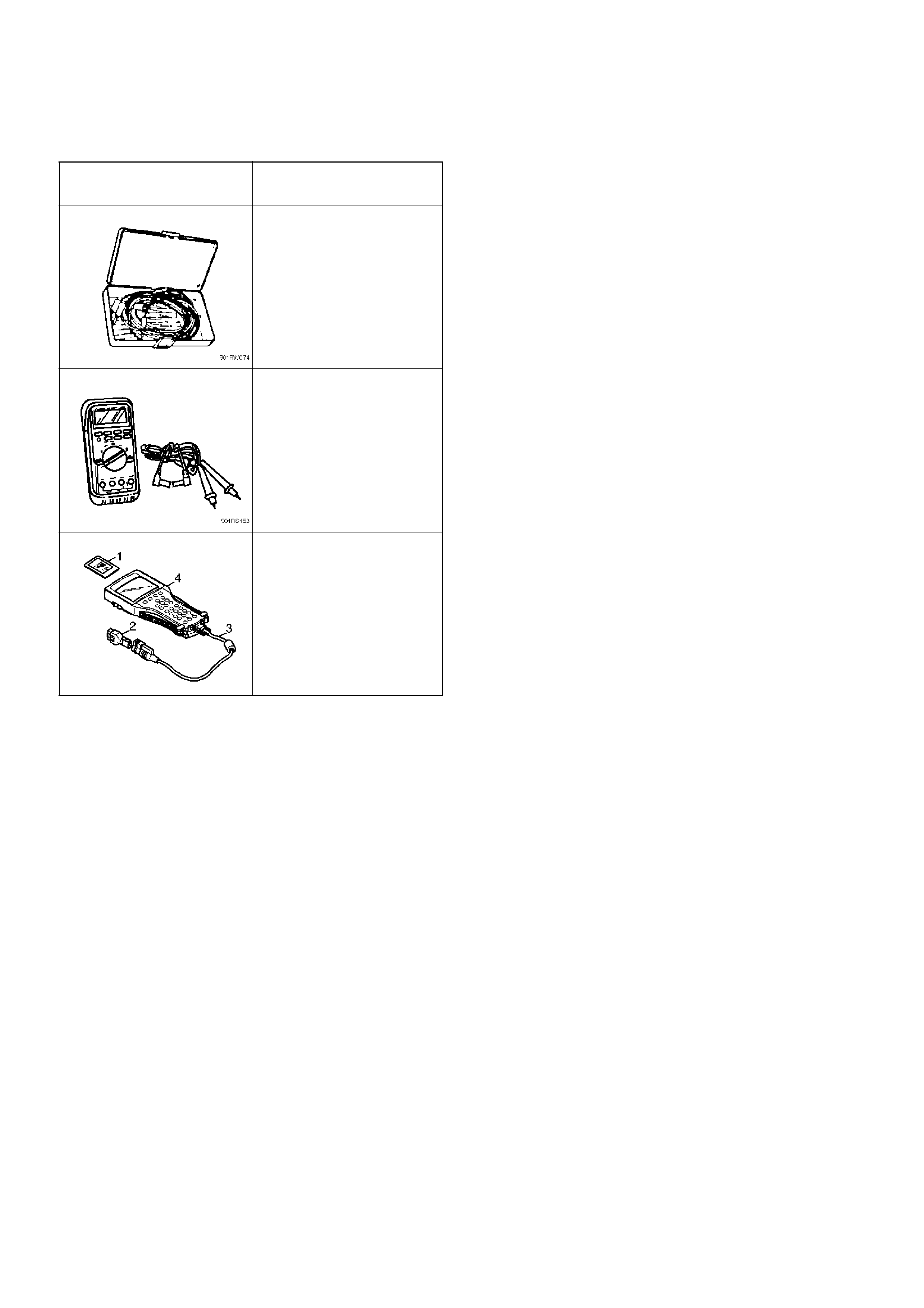
Special Tools
ILLUSTRATION TOOL NO.
TOOL NAME
5–8840–0385–0
(J–35616)
Connector test adapter kit
5–8840–0366–0
(J–39200)
High impedance
multimeter
(1) PCMCIA Card
(2) SAE 16/19 Adapter
(3) DLC Cable
(4) Tech–2