
SECTION 5B - ANTI-LOCK BRAKE SYSTEM
Service Precaution
Electronic Hydraulic Control Unit
Electronic Hydraulic Control Unit
and Associated Parts
Removal
Installation
G-Sensor
Removal
Inspection and Repair
Installation
Front Wheel Speed Sensor
Front Wheel Speed Sensor
and Associated Parts
Removal
Inspection and Repair
Installation
Rear Wheel Speed Sensor
Rear Wheel Speed Sensor
and Associated Parts
Removal
Inspection and Repair
Installation
Service Precaution
WARNING: IF SO EQUIPPED WITH A
SUPPLEMENTAL RESTRAINT SYSTEM(SRS),
REFER TO THE SRS COMPONENT AND WIRING
LOCATION VIEW IN ORDER TO DETERMINE
WHETHER YOU ARE PERFORMING SERVICE ON
OR NEAR THE SRS COMPONENTS OR THE SRS
WIRING. WHEN YOU ARE PERFORMING SERVICE
ON OR NEAR THE SRS COMPONENTS OR THE
SRS WIRING, REFER TO THE SRS SERVICE
INFORMATION. FAILURE TO FOLLOW WARNINGS
COULD RESULT IN POSSIBLE AIR BAG
DEPLOYMENT, PERSONAL INJURY, OR
OTHERWISE UNNEEDED SRS SYSTEM REPAIRS.
CAUTION: Always use the correct fastener in the
proper location. When you replace a fastener, use
ONLY the exact part number for that application.
HOLDEN will call out those fasteners that require a
replacement after removal. HOLDEN will also call
out the fasteners that require thread lockers or
thread sealant. UNLESS OTHERWISE SPECIFIED,
do not use supplemental coatings (Paints, greases,
or other corrosion inhibitors) on threaded fasteners
or fastener joint interfaces. Generally, such
coatings adversely affect the fastener torque and
the joint clamping force, and may damage the
fastener. When you install fasteners, use the correct
tightening sequence and specifications. Following
these instructions can help you avoid damage to
parts and systems.
CAUTION: Replace all components included in
repair kits used to service this system. Lubricate
rubber parts with clean, fresh brake fluid to ease
assembly. Do not use shop air with in-line
lubricators on brake parts, as damage to rubber
components may result. If any hydraulic component
is removed or brake line disconnected, it may be
necessary to bleed part or all of the brake system.
NOTE: The use of rubber hoses or parts other than
those furnished specifically for the Anti-lock Brake
System may lead to functional problems requiring major
overhaul.
Techline
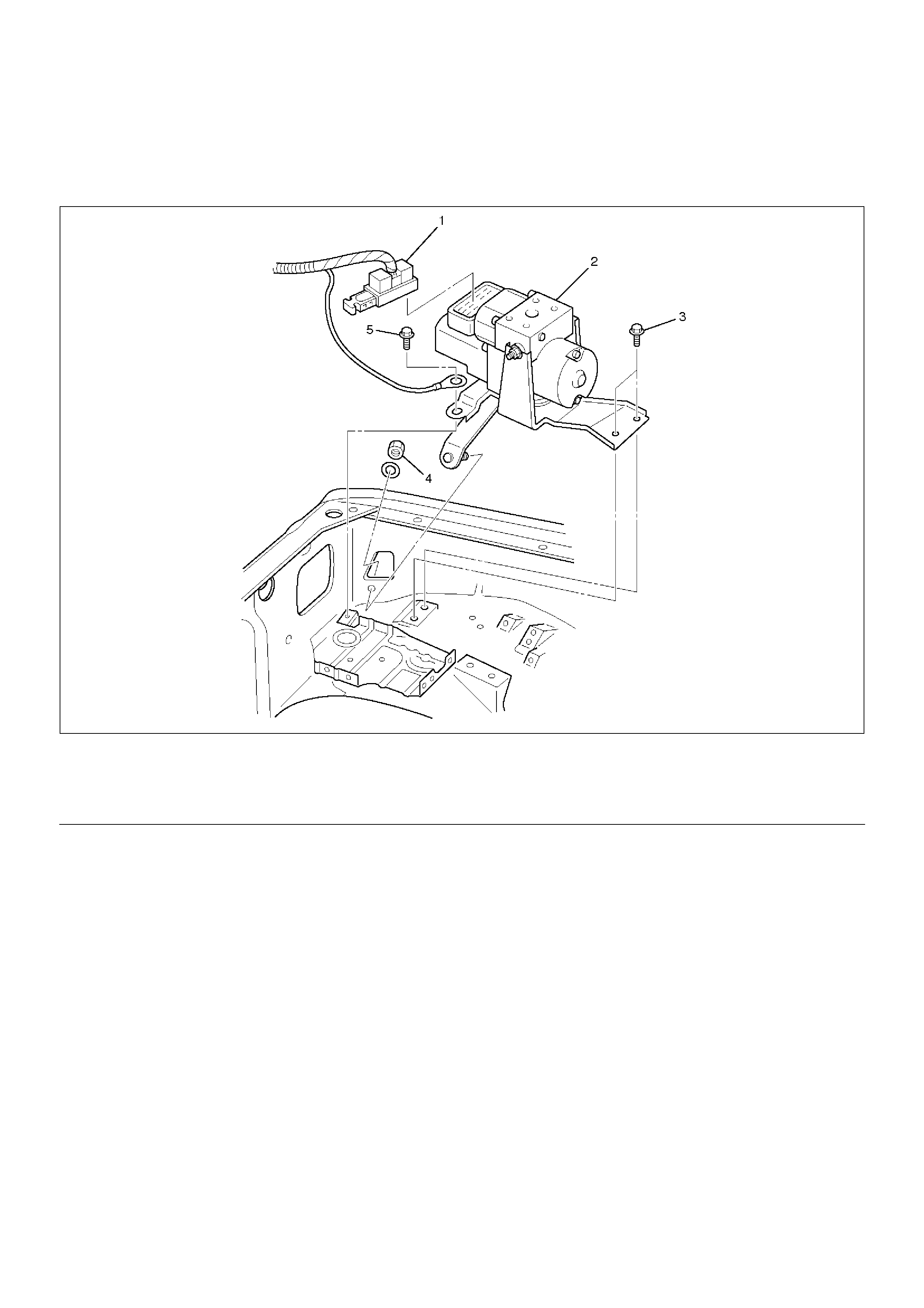
Electronic Hydraulic Control Unit
Electronic Hydraulic Control Unit and Associated Parts
350RW013
EndOFCallout
Removal
1.Remove battery ASM.
2.Remove harness connector.
3.Remove EHCU fixing nuts.
4.Remove brake pipes.
•After disconnecting brake pipe, cap or tape the
openings of the brake pipe to prevent the entry of
foreign matter.
5.Remove hydraulic unit fixing nuts.
Installation
To install, follow the removal steps in the reverse order,
noting the following points:
Torque
Hydraulic unit fixing nuts : 22 N·m (2.2kg·m/16
lbft)
Ground cable : 14 N·m (1.4kg·m/10 lbft)
Brake pipe (joint bolts) : 16 N·m (1.6kg·m/12 lbft)
•After installing the hydraulic unit, bleed brakes
completely. Refer to Servicing in Power Assisted
Brake System section.
Legend
(1) Connector
(2) Hydraulic Unit ASM
(3) Bolts
(4) Nut
(5) Bolt
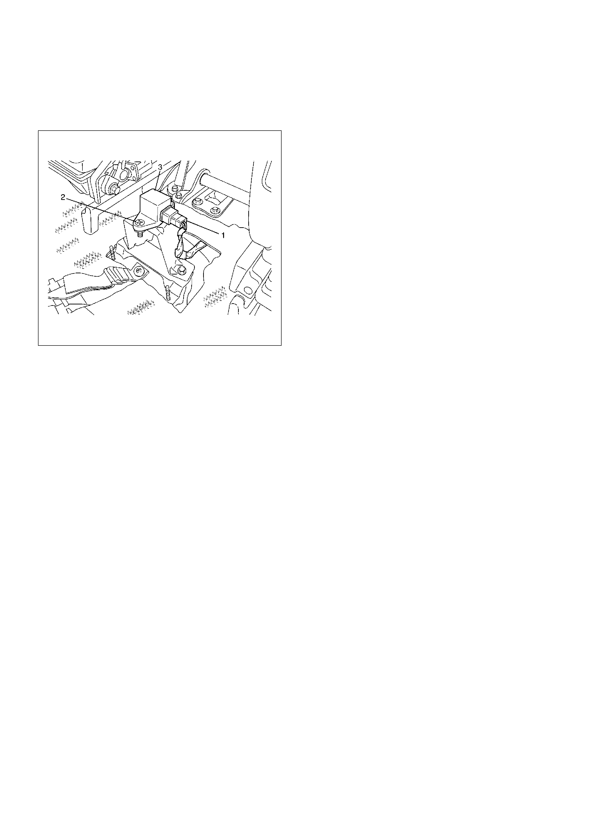
G-Sensor
Removal
350RX001
1.Remove center console.
•Refer to Consoles in Body and Accessories
section.
2.Remove clip from G-sensor connector (1), then
disconnect connector.
3.Remove G-sensor assembly fixing bolt (2).
4.Remove G-sensor assembly (3).
Inspection and Repair
Refer to Chart B-5 in Brake Control System section.
Installation
1.Install G-sensor assembly (3).
•Care should be taken so that the G-sensor is not
installed in the wrong direction.
2.Install G-sensor assembly fixing bolt (2).
•Tighten the fixing bolt to the specified torque.
Torque : 10 N·m (1.0kg·m/87 lbin)
3.Install G-sensor wiring connector (1).
4.Install center console.
•Refer to Consoles in Body and Accessories
section.
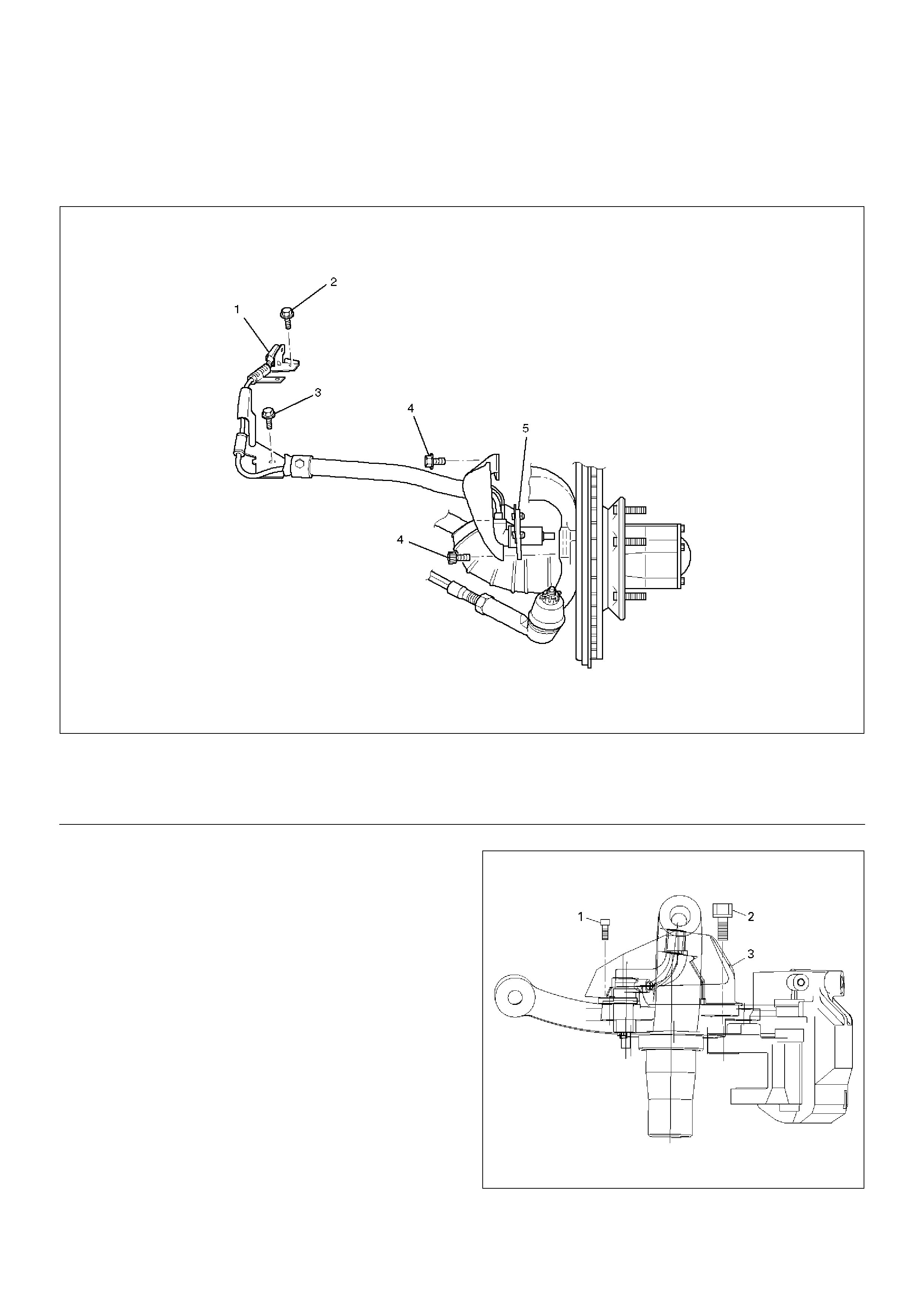
Front Wheel Speed Sensor
Front Wheel Speed Sensor and Associated Parts
350RW012
EndOFCallout
Removal
1. Remove speed sensor connector.
2. Remove sensor cable fixing bolt (Upper side).
3. Remove sensor cable fixing bolt (Lower side).
4. Remove the speed sensor cable fixing bolts (1) and
caliper fixing bolt (2) from caliper side speed sensor
cable bracket (3).
350RW010
5. Remove speed sensor.
Legend
(1) Speed Sensor Connector
(2) Sensor Cable Fixing Bolt (Upper side)
(3) Sensor Cable Fixing Bolt (Lower side)
(4) Sensor Cable Fixing Bolt (Sensor side)
(5) Speed Sensor
Inspection and Repair
1.Check the speed sensor pole piece for presence of
foreign materials; remove any dirt, etc.
2.Check the pole piece for damage; replace speed
sensor if necessary.
3.Check the speed sensor cable for short or open
circuit, and replace with a new one if necessary.
To check for cable short or open, bend or stretch the
cable while checking for continuity.
4.Check the sensor ring for damage including tooth
chipping, and if damaged, replace the sensor ring
assembly. Refer to Front Hub and Disc in Drive
Shaft System section.
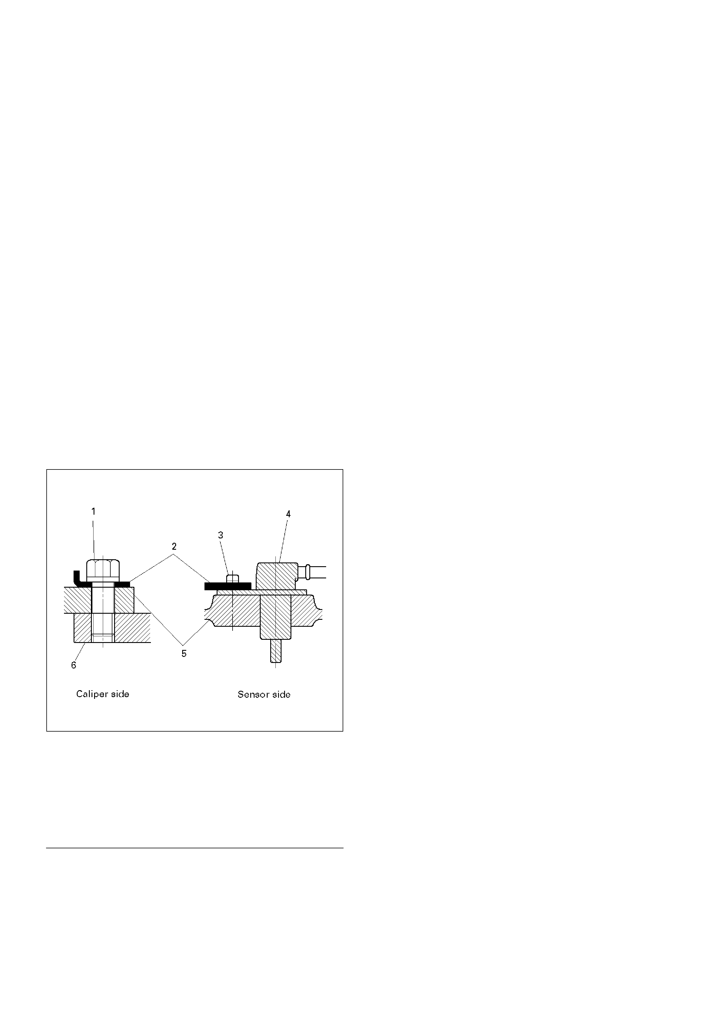
Installation
1. Install speed sensor and take care not to hit the
speed sensor pole piece during installation.
2. Install speed sensor fixing bolt and tighten the fixing
bolt to the specified torque.
Torque
Sensor side : 8 N·m (0.8kg·m/69 lbin)
Caliper side : 155 N·m (15.8kg·m/115 lbft)
350RW011
EndOFCallout
3. Install speed sensor cable fixing bolt (Lower side)
and tighten the fixing bolt to the specified torque.
Torque : 24 N·m (2.4kg·m/18 lbft)
4. Install speed sensor cable fixing bolt (Upper side)
and tighten the fixing bolt to the specified torque.
Torque : 6 N·m (0.6kg·m/52 lbin)
NOTE: Confirm that a white line marked on the cable is
not twisted when connecting the speed sensor cable.
5. Install speed sensor connector.
Legend
(1) Caliper Fixing Bolt
(2) Bracket
(3) Sensor Fixing Bolt
(4) Sensor
(5) Knuckle
(6) Brake Caliper
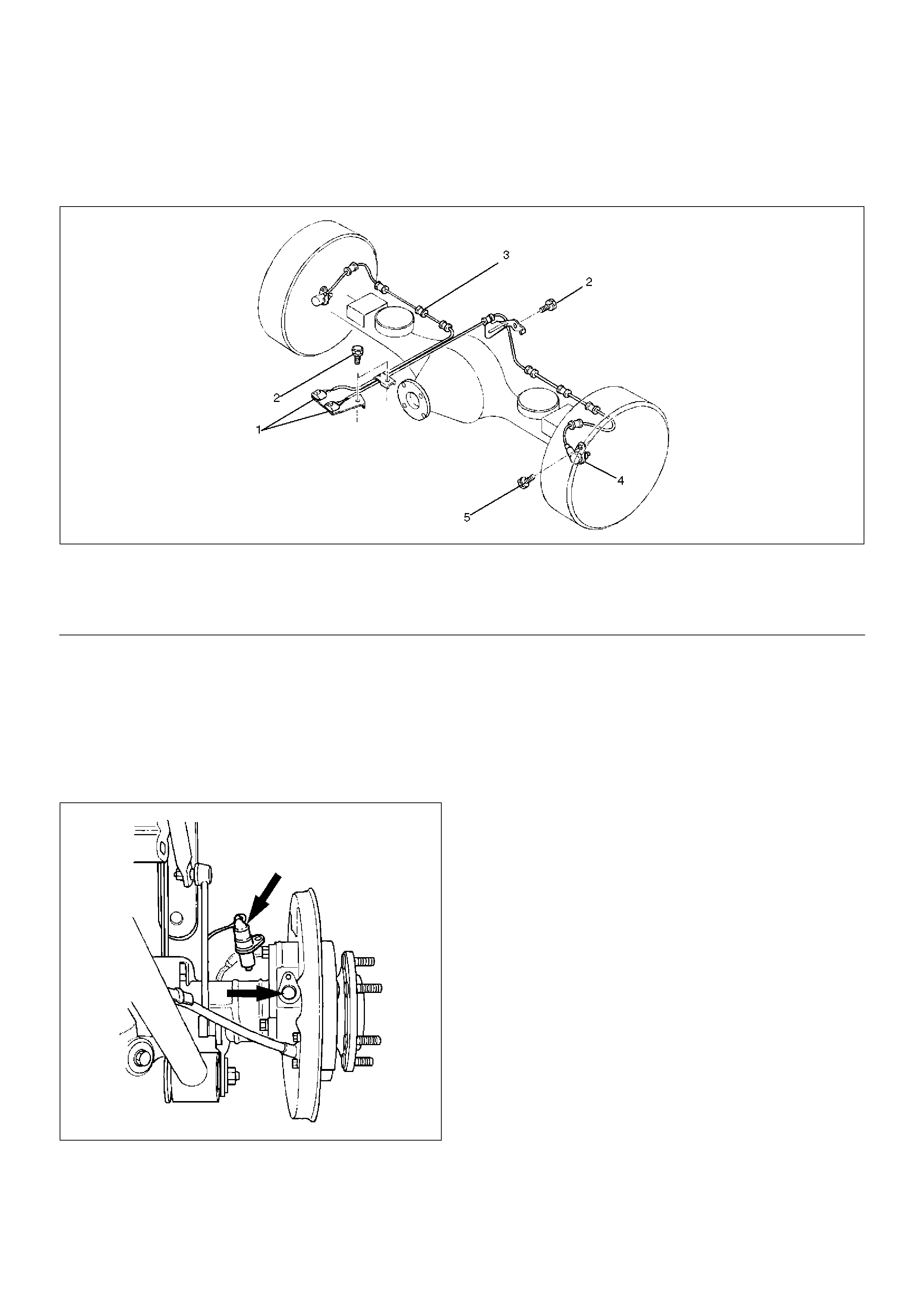
Rear Wheel Speed Sensor
Rear Wheel Speed Sensor and Associated Parts
350RW008
EndOFCallout
Removal
1.Remove speed sensor connector.
2.Remove clip.
3.Remove sensor cable fixing bolt.
4.Remove sensor fixing bolt.
5.Remove speed sensor.
350RS035
Inspection and Repair
1.Check the speed sensor pole piece for presence of
foreign materials; remove any dirt, etc.
2.Check the pole piece for damage, and replace the
speed sensor if necessary.
3.Check the speed sensor cable for a short or an
open, and replace with a new one if necessary. To
check for cable short or open, bend or stretch the
cable while checking for continuity.
4.Check the sensor ring for damage including tooth
chipping. If damaged replace the axle shaft
assembly. Refer to Front Hub and Disc in Drive
Shaft System section.
Installation
1. Install the speed sensor and take care not to hit the
speed sensor pole piece during installation.
2. Install the sensor fixing bolt and tighten it to the
specified torque.
Torque : 18 N·m (1.8kg·m/13 lbft)
3. Install the sensor cable fixing bolt and tighten it to
the specified torque.
Torque : 24 N·m (2.4kg·m/18 lbft)
NOTE: Confirm that the cable is not twisted when
connecting the speed sensor cable.
4. Install clip.
5. Install speed sensor connector.
Legend
(1) Speed Sensor Connector
(2) Sensor Cable Fixing Bolt
(3) Clip (11 pieces)
(4) Speed Sensor
(5) Sensor Fixing Bolt