
SECTION 5C POWER ASSISTED BRAKE SYSTEM
Service Precaution
Brake System Diagnosis
Troubleshooting
Main Data and Specifications
Service Standard
Servicing
Fixing Torque
Special Tools
General Description
Master Cylinder
Vacuum Booster
Disk Brakes
On-Vehicle Service
Brake Hose Replacement
Brake Pipe Replacement
P & B Valve
P & B Valve Replacement
Load Sensing Proportioning Valve (LSPV)
Brake Pedal Replacement
Stoplight Switch Replacement
Fluid Reservoir Tank
Master Cylinder Assembly
Vacuum Booster Assembly
Exterior Components

Front Disc Brakes
Brake Pads Replacement
Caliper Replacement
Rebuilding the Caliper
Rear Disc Brakes
Brake Pads Replacement
Caliper Replacement
Rebuilding the Caliper
Unit Repair
Master Cylinder
Vacuum Booster
SERVICE PRECAUTION
WARNING:
IF SO EQUIPPED WITH A SUPPLEMENTAL RESTRAINT SYSTEM (SRS), REFER TO THE SRS COMPONENT
AND WIRING LOCATION VIEW IN ORDER TO DETERMINE WHETHER YOU ARE PERFORMING SERVICE ON
OR NEAR THE SRS COMPONENTS OR THE SRS WIRING. WHEN YOU ARE PERFORMING SERVICE ON OR
NEAR THE SRS COMPONENTS OR THE SRS WIRING, REFER TO THE SRS SERVICE INFORMATION.
FAILURE TO FOLLOW WARNINGS COULD RESULT IN POSSIBLE AIR BAG DEPLOYMENT, PERSONAL
INJURY, OR OTHERWISE UNNEEDED SRS SYSTEM REPAIRS.
CAUTION:
Always use the correct fastener in the proper location. When you replace a fastener, use ONLY the exact
part number for that application. ISUZU will call out those fasteners that require a replacement after
removal. ISUZU will also call out the fasteners that require thread lockers or thread sealant. UNLESS
OTHERWISE SPECIFIED, do not use supplemental coatings (Paints, greases, or other corrosion inhibitors)
on threaded fasteners or fastener joint interfaces. Generally, such coatings adversely affect the fastener
torque and the joint clamping force, and may damage the fastener. When you install fasteners, use the
correct tightening sequence and specification. Following these instructions can help you avoid damage to
parts and systems.

BRAKE SYSTEM DIAGNOSIS
ROAD TESTING THE BRAKES
Brake Test
Brakes should be tested on a dry, clean, reasonably
smooth and level roadway. A true test of brake
performance cannot be made if the roadway is wet,
greasy or covered with loose dirt so that all tires do
not grip the road equally. Testing will also be
adversely affected if the roadway is crowned so as to
throw the weight of the vehicle toward wheels on one
side or if the roadway is so rough that wheels tend to
bounce. Test the brakes at different vehicle speeds
with both light and heavy pedal pressure; however,
avoid locking the wheels and sliding the tires. Locked
wheels and sliding tires do not indicate brake
efficiency, since heavily braked but turning wheels
will stop the vehicle in less distance than locked
wheels. More tire-to-road friction is present with a
heavily braked turning tire then with a sliding tire.
The standard brake system is designed and balanced
to avoid locking the wheels except at very high
deceleration levels.
It is designed this way because the shortest stopping
distance and best control is achieved without brake
lock-up.
Because of high deceleration capability, a firmer pedal
may be felt at higher deceleration levels.
External Conditions That Affect Brake
Performance
1.Tires: Tires having unequal contact and grip on the
road will cause unequal braking. Tires must be
equally inflated, identical in size, and the tread
pattern of right and left tires must be
approximately equal.
2.Vehicle loading: A heavily loaded vehicle requires
more braking effort.
3.Wheel Alignment: Misalignment of the wheels,
particularly in regard to excessive camber and
caster, will cause the brakes to pull to one side.
BRAKE FLUID LEAKS
With engine running at idle and the transmission in
“Neutral”, depress the brake pedal and hold a
constant foot pressure on the pedal. If pedal gradually
falls away with the constant pressure, the hydraulic
system may be leaking.
Check the master cylinder fluid level. While a slight
drop in reservoir level will result from normal lining
wear, an abnormally low level in resevoir indicates a
leak in the system. The hydraulic system may be
leaking internally as well as externally. Refer to
“Master Cylinder Inspection”. Also, the system may
appear to pass this test but still have slight leakage. If
fluid level is normal, check the vacuum booster push

rod length. If an incorrect length push rod is found,
adjust or replace the push rod. Check the brake pedal
travel and the parking brake adjustment.
When checking the fluid level, the master cylinder
fluid level may be low from the “MAX” mark if the
front and rear linings are worn. This is not abnormal.
WARNING LIGHT OPERATION
When the ignition switch is in the START position, the
“BRAKE” warning light should glow and go OFF when
the ignition switch returns to the ON position.
The following conditions will activate the “BRAKE”
light:
1.Parking brake applied. The light should be ON
whenever the parking brake is applied and the
ignition switch is ON.
2.Low fluid level. A low fluid level in the master
cylinder will turn the “BRAKE” light ON.
3.During engine cranking the “BRAKE” light should
remain ON. This notifies the driver that the
warning circuit is operating properly.
4.Low vacuum warning light. The vacuum warning
device is equipped on the diesel engine equipped
vehicles. The “BRAKE” light comes on when the
reserved vacuum is lowered to a critical level or
power brake line is damaged.
NOTE:
Depressing the brake pedal repeatedly may cause the
brake warning light to come ON when the engine is
running at idling speed or at low speed. This is
because the amount of vacuum is used more than
that supplied by the vacuum pump, however, no
problem will occur actually.
If the lamp is still lighting even after 2 or 3 seconds at
idling speed, the vacuum line may be defective.
ANTILOCK BRAKE SYSTEM (ABS)
Refer to Brake Control System for inspection and
diagnosis procedure of the hydraulic unit.

TROUBLESHOOTING
Condition Possible Cause Correction
Brake Pull 1. Tire inflation pressures unequal. 1. Adjust
2. Front wheel alignment incorrect. 2. Adjust
3. Unmatched tires on same axle. 3. Tire with approx. the same amount of
tread should be used on the same axle.
4. Restricted brake pipes or hoses. 4. Check for soft hoses and damaged
lines. Replace with new hoses and new
double-walled steel brake piping.
5. Water or oil on brake pads. 5. Clean or replace.
6. Brake pads hardened. 6. Replace.
7. Brake pads worn excessively. 7. Replace.
8. Brake rotor worn or scored. 8. Grind or replace.
9. Disc brake caliper malfunctioning. 9. Clean or replace.
10. Front hub bearing preload incorrect. 10. Adjust or replace.
11. Loose suspension parts. 11. Check all suspension mountings.
12. Loose calipers. 12. Check and tighten bolts to specifications.
Brake 1. Excessive lateral runout. 1. Check per instructions.
Roughness-or If not within specifications, replace or
Chatter machine the rotor.
(Pulsates) 2. Parallelism not within specifications. 2. Check per instructions.
If not within specifications, replace or
machine the rotor.
3. Wheel bearings not adjusted. 3. Adjust wheel bearings to correct
specifications.
4. Pad reversed (steel against iron). 4. Replace brake pad and machine rotor
to within specifications.
Excessive 1. Malfunctioning vacuum booster. 1. Check vacuum booster operation and
Pedal repair, if necessary.
Effort 2. Partial system failure. 2. Check front and rear brake system for
failure and repair. Also, check brake
warning light. If a failed system is
found, the light should indicate a
failure.
3. Excessively worn pad. 3. Check and replace pads in sets.
4. Piston in caliper stuck or sluggish. 4. Remove caliper and rebuild.
5. Fading brakes due to incorrect pad. 5. Remove and replace with original
equipment pad or equivalent.
6. Vacuum leak to vacuum booster. 6. Check for ruptured or loose hose.
7. Check direction of check valve within 7. Correct vacuum hose direction.
vacuum hose.
8. Grease on the brake pads. 8. Replace or clean.
Excessive 1. Air in hydraulic circuit. 1. Bleed hydraulic circuit.
Brake Pedal 2. Level of brake fluid in resevoir too low. 2. Replenish brake fluid resevoir to
Travel specified level and bleed hydraulic
circuit as necessary.
3. Master cylinder push rod clearance 3. Adjust.
excessive.
4. Leakage in hydraulic system. 4. Correct or replace defective parts.

Condition Possible Cause Correction
Brake Drag 1. Master cylinder pistons not returning 1. Adjust stop light switch and vacuum
correctly. booster operating rod. If necessary,
rebuild.
2. Restricted brake pipes or hoses. 2. Check for soft hoses or damaged pipes,
and replace with new hoses and new
double-walled steel brake piping.
3. Parking brake maladjusted. 3. Adjust.
4. Parking brake lining clearance 4. Adjust.
insufficient.
5. Brake pedal free play insufficient. 5. Adjust brake pedal height or power
cylinder operating rod.
6. Piston in master cylinder sticking. 6. Replace.
7. Piston in disc brake caliper sticking. 7. Replace piston seals.
8. Brake pads sticking in caliper. 8. Clean.
9. Return spring weakened. 9. Replace.
10. Parking brake binding. 10. Overhaul parking brakes and correct.
11. Front hub bearing preload incorrect. 11. Adjust or replace.
12. Parking brake shoes not returning. 12. Correct or replace brake back plate and
brake shoe as necessary.
13. Obstructions in hydraulic circuit. 13. Clean.
14. Rotor warped excessively. 14. Grind or replace.
15. Rear brake drum distorted. 15. Grind or replace.
16. Parking cable sticking. 16. Clean or replace.
Grabbing or 1. Malfunctioning vacuum booster. 1. Check operation and correct as
Uneven necessary.
Braking Action 2. Binding brake pedal mechanism. 2. Check and lubricate, if necessary.
(All conditions 3. Corroded caliper assembly. 3. Clean and lubricate.
listed under
“Pulls”)
Brake Noisy 1. Brake pads worn. 1. Replace.
2. Brake pads hardened. 2. Replace.
3. Brake pads in poor contact with rotor. 3. Correct.
4. Brake disc(s) warped, worn or 4. Grind or replace.
damaged.
5. Disc brake anti-squeak shims fatigued. 5. Replace.
6. Front hub bearings loose or preload is 6. Adjust or replace.
incorrect.
7. Brake disc rusted. 7. Grind or replace.
Poor Brake 1. Master cylinder faulty. 1. Correct or replace.
Action 2. Vacuum booster faulty. 2. Correct or replace.
3. Level of brake fluid in reservoir too 3. Replenish and bleed.
low.
4. Air in hydraulic circuit. 4. Bleed.
5. Disc brake caliper faulty. 5. Clean or replace.
6. Water or oil on brake pads. 6. Clean or replace.
7. Brake pads in poor contact with rotor. 7. Correct.
8. Brake pads worn. 8. Replace.
9. Brake disc rusted. 9. Grind or replace.
10. Check valve in vacuum hose faulty. 10. Correct or replace.

MAIN DATA AND SPECIFICATIONS
MASTER CYLINDER
Type Dual-circuit
Piston Bore Diameter mm (in) 25.4 (1.000)
VACUUM BOOSTER
Diaphragm Diameter
Front; mm (in) 205 (8.07) (Gasoline) / 180 (7.09) (Diesel)
Rear; mm (in) 230 (9.06) (Gasoline) / 205 (8.07) (Diesel)
Push Rod Stroke mm (in) More than 32.0 (1.26)
Plunger Diameter mm (in) 10.13 (0.399)
Push Rod Diameter mm (in) 27.4 (1.08)
FRONT DISC BRAKE
Type Floating, Pin Slide
Pad Dimension cm2(in2) 55 (8.52)
Adjusting Method Self-adjusting
Piston Diameter mm (in) 60.33 (2.38)
Disc (Rotor) Type Ventilated
Disc (Rotor) Thickness mm (in) 26 (1.02)
Disc (Rotor) Effective Diameter mm (in) 222 (8.74)
REAR DISC BRAKE
Type Floating, Pin Slide
Pad Dimension cm2(in2) 33 (5.11)
Adjusting Method Self-adjusting
Piston Diameter mm (in) 41.3 (1.63)
Disc (Rotor) Type Ventilated
Disc (Rotor) Thickness mm (in) 18 (0.71)
Disc (Rotor) Effective Diameter mm (in) 269.2 (10.60)

SERVICE STANDARD
HYDRAULIC BRAKE FLUID DOT 3 grade
BRAKE PEDAL
Pedal Free Play mm (in) 6 to 10 (0.23 to 0.39)
Pedal Height (LHD / RHD) mm (in) 208 to 218 (8.19 to 8.58) / 211 to 221 (8.31 to 8.70)
Stop Light Switch Clearance mm (in) 0 to 0.2 (0 to 0.008)
FRONT DISC BRAKE
Pad Thickness Minimum Limit mm (in) 1.0 (0.039)
Disc (Rotor) Maximum Runout mm (in) 0.13 (0.005)
Disc (Rotor) Maximum Parallelism mm (in) 0.010 (0.0004)
Disc (Rotor) Minimum Wear
Dimensions (Thickness) mm (in) 24.60 (0.969)
Disc (Rotor) Minimum Refinish
Dimensions (Thickness) mm (in) 24.97 (0.983)
REAR DISC BRAKE
Pad Thickness Minimum Limit mm (in) 1.0 (0.039)
Disc (Rotor) Maximum Runout mm (in) 0.13 (0.005)
Disc (Rotor) Maximum Parallelism mm (in) 0.010 (0.0004)
Disc (Rotor) Minimum Wear
Dimensions (Thickness) mm (in) 16.60 (0.654)
Disc (Rotor) Minimum Refinish
Dimensions (Thickness) mm (in) 16.97 (0.668)

SERVICING
FILLING MASTER CYLINDER RESERVOIR
CAUTION:
1) Use only specified brake fluid. Do not use any
fluid which contains a petroleum base. Do not
use a container which has been used for
petroleum based fluids or a container which is
wet with water. Petroleum based fluids will
cause swelling and distortion of rubber parts in
the hydraulic brake system. Water mixed with
brake fluid lowers the fluid boiling point. Keep all
fluid containers capped to prevent
contamination.
2) Always fill the master cylinder reservoid when
the engine is cold.
3) Never allow the brake fluid to come in contact
with the painted surfaced.
The master cylinder reservoir must be kept properly
filled to ensure adequate reserve and to prevent air
and moisture from entering the hydraulic system.
However, because of expansion due to heat absorbed
from the brakes and the engine, the reservoir must not
be overfilled. The brake fluid reservoir is on the
master cylinder, which is located under the hood on
the driver side of the cowl. Thoroughly clean reservoir
cap before removal to avoid getting dirt into reservoir.
Remove cap and diaphragm. Add fluid as required to
bring level to the “MAX” mark on the reservoir tank.
Use “DOT 3“ Hydraulic Brake Fluid. If the fluid cap
diaphragm is stretched, return it to the original
position before installing.
DETERIORATION OF BRAKE FLUID
Using any other brake fluid than speficied or brake
fluid with mineral oil or water mixed in will drop the
boiling point of brake fluid. It may, in turn, reuslt in
vapor lock or deteriorated rubber parts of the
hydraulic system. Be sure to change brake fluid at
specified intervals.
If rubber parts are deteriorated, remover all the
system parts and clean them with alcohol. Prior to
reassembly, dry the cleaned parts with air to remove
the alcohol. Replace all hoses and rubber parts of the
system.
LEAKAGE OF BRAKE FLUID
With engine idling, set shift lever in the neutral
position and continue to depress brake pedal at a
constant pedal application force.
Should the pedal stroke become deeper gradually,
leak from the hydraulic pressure system is possible.
Make sure by visual check that there is no leak.
BLEEDING BRAKE HYDRAULIC SYSTEM
A bleeding operation is necessary to remove air from
the hydraulic brake system whenever air is introduced
into the hydraulic system. It may be necessary to
bleed the hydraulic system at all four brakes if air has
been introduced through a low fluid level or by
disconnecting brake pipes at the master cylinder. If a
brake pipe is disconneted at one wheel, only that
wheel cylinder/caliper needs to be bled. If pipes are
disconnected at any fitting located between master
cylinder and brakes, then the brake system served by
the disconnected pipe must be bled.
1. For 4-wheel Antilock Brake System (ABS)
equipped vehicle, be sure to remove the ABS main
fuse 40A located at the relay and fuse box before
bleeding air. If you attempt to bleed air without
removing the main fuse, air cannot be let out
thoroughly, and this may cause damage to the
hydraulic unit. After bleeding air, be sure to
replace the ABS main fuse back to its original
position.
2. Set the parking brake completely, then start the
engine.
NOTE:
The vacuum booster will be damaged if the bleeding
operation is performed with the engine off.
3. Remove the master cylinder reservoir cap.
4. Fill the master cylinder reservoir with brake fluid.
Keep the reservoir at least half full during the air
bleeding operation.
5. Always use new brake fluid for replenishment.
6. In replenishing brake fluid, take care that air
bubbles do not enter the brake fluid.
•When the master cylinder is replaced or
overhauled, first bleed the air from the master
cylinder, then from each wheel cylinder and
caliper following the procedures described
below.
Bleeding the Master Cylinder
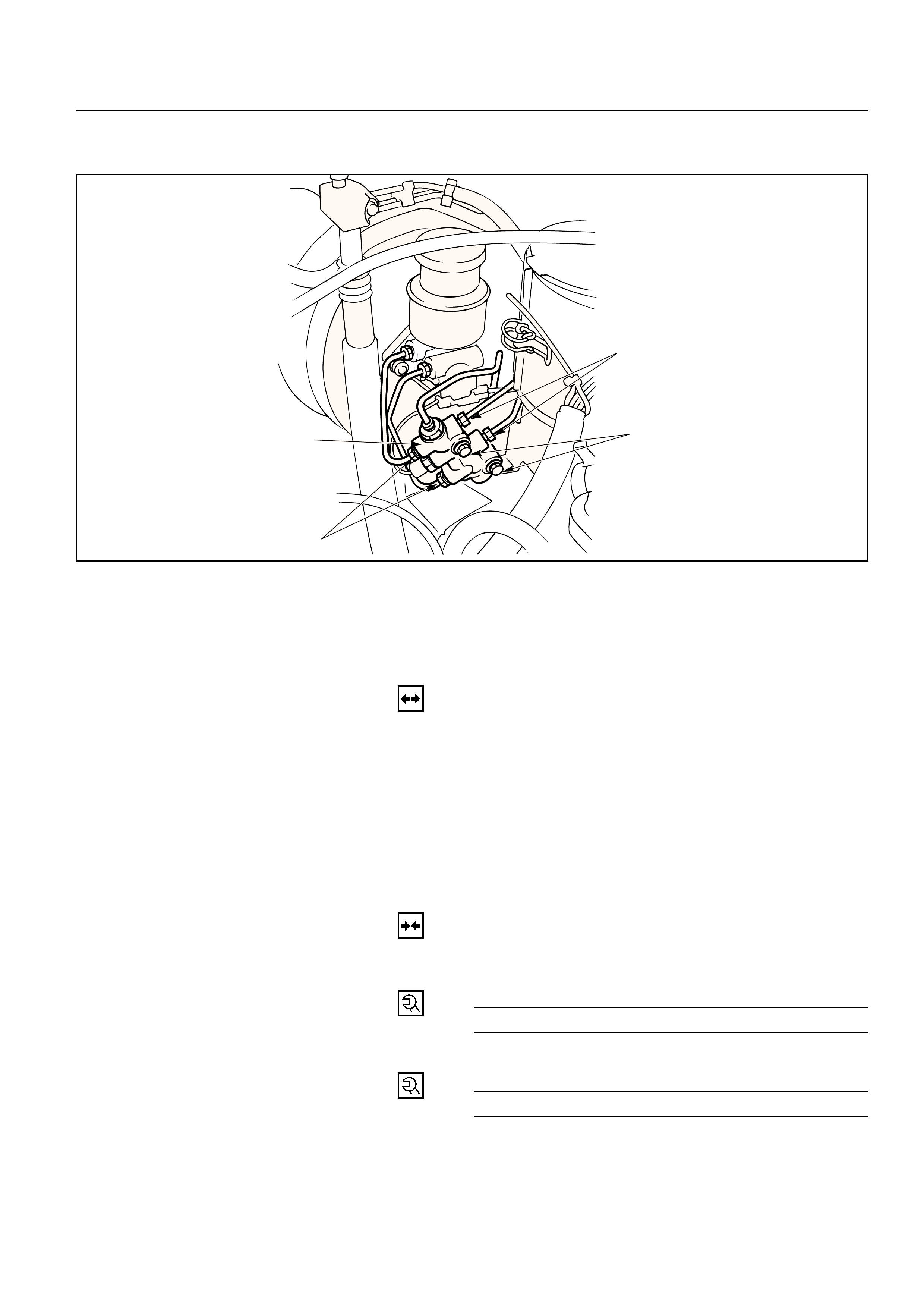
7. Disconnect the rear wheel brake pipe 1from the
master cylinder. Check the fluid level and
replenish as necessary. If replenished, leave the
system for at least one minute.
8. Depress the brake pedal slowly once and hold it
depressed.
9. Completely seal the delivery port of the master
cylinder where the pipe was disconnected with
your finger, then release the brake pedal slowly.
10. Release your finger from the delivery port when
the brake pedal returns completely.
11. Repeat steps 7 through 9 until the brake fluid
comes out of the delivery port during step 7.
NOTE:
Do not allow the fluid level in the reservoir to go
below the half-way mark.
2
1

12. Reconnect the brake pipe 1to the master cylinder
and tighten the pipe.
13. Depress the brake pedal slowly once and hold it
depressed.
14. Loosen the rear wheel brake pipe 1at the master
cylinder.
15. Retighten the brake pipe, then release the brake
pedal slowly.
16. Repeat steps 13 through 15 until no air comes out
from the port when the brake pipe is loosened.
NOTE:
Be very careful not to allow the brake fluid to come in
contact with painted surfaces.
17. Bleed the air from the front wheel brake pipe
connection 2by repeating steps 7 through 16.
Bleeding the Caliper
18. Bleed the air from each wheel in the order listed
below.
LHD models:
1) Right rear caliper
2) Left rear caliper
3) Load sensing proportioning valve (only for
Europe and South Africa)
4) Right front caliper
5) Left front caliper
RHD models:
1) Left rear caliper
2) Right rear caliper
3) Load sensing proportioning valve (only for
Europe and South Africa)
4) Left front caliper
5) Right front caliper
Conduct air bleeding from the wheels in the above
order. If no brake fluid comes out, it suggests that air
is mixed in the master cylinder. In this case, bleed air
from the master cylinder in accordance with Steps 7
through 17, and then bleed air from the caliper.
19. Place the proper size box end wrench over the
bleeder screw.
20. Cover the bleeder screw with a transparent tube,
and submerge the free end of the transparent tube
in a transparent container containing brake fluid.
21. Pump the brake pedal slowly three (3) times
(once/sec), then hold it depressed.
22. Loose the bleeder screw until fluid flows through
the tube.
23. Retighten the bleeder screw.
24. Release the brake pedal slowly.
25. Repeat step 21 through 24 until the air is
compeletely removed. It may be necessary to
repeat the bleeding procedure 10 or more times
for front wheels and 15 or more times for rear
wheels.
26. Go to the next wheel in the sequence after each
wheels is bled. Be sure to monitor reservoir fluid
level.

27.Depress the brake pedal to check if you feel
“sponginess” after the air has been removed from
all wheel cylinders and calipers. If the pedal feels
“spongy”, the entire bleeding procedure must be
repeated.
28.After the bleeding operation is completed on each
individual wheel, check the level of brake fluid in
the reservoir and replenish up to the “MAX” level if
necessary.
29.Attach the reservoir cap.
•If the diaphragm inside the cap is deformed,
reform it and install.
30.Stop the engine.
FLUSHING BRAKE HYDRAULIC SYSTEM
It is recommended that the entire hydraulic system be
thoroughly flushed with clean brake fluid whenever
new parts are installed in the hydraluic system.
Approximately one quart of fluid is required to flush
the hydraulic system.
The system must be flushed if there is any doubt as to
the grade of fluid in the system or if fluid has been
used which contains the slightest trace of mineral oil.
All rubber parts that have been subjected to a
contaminated fluid must be replaced.
BRAKE PIPES AND HOSES
The hydraulic brake system components are
interconnected by special steel piping and flexible
hoses. Flexible hoses are used between the frame and
the front calipers, the frame and rear axle case and the
rear axle and the rear calipers.
When the hydraulic pipes have been disconnected for
any reason, the brake system must be bled after
reconnecting the pipe; refer to “Bleeding Brake
Hydraulic System” in this section.
BRAKE HOSE INSPECTION
The brake hoses should be inspected at least twice a
year. The brake hose assembly should be checked for
road hazard, cracks and chafing of the outer cover,
and for leaks and blisters. Inspect for proper routing
and mounting of the hose. A brake hose that rubs on
suspension components will wear and eventually fail.
A light and mirror may be needed for an adequate
inspection. If any of the above conditions are
observed on the brake hose, adjust or replace the
hose as necessary.
CAUTION:
Never allow brake components such as calipers to
hang from the brake hoses, as damage to the hoses
may occur.

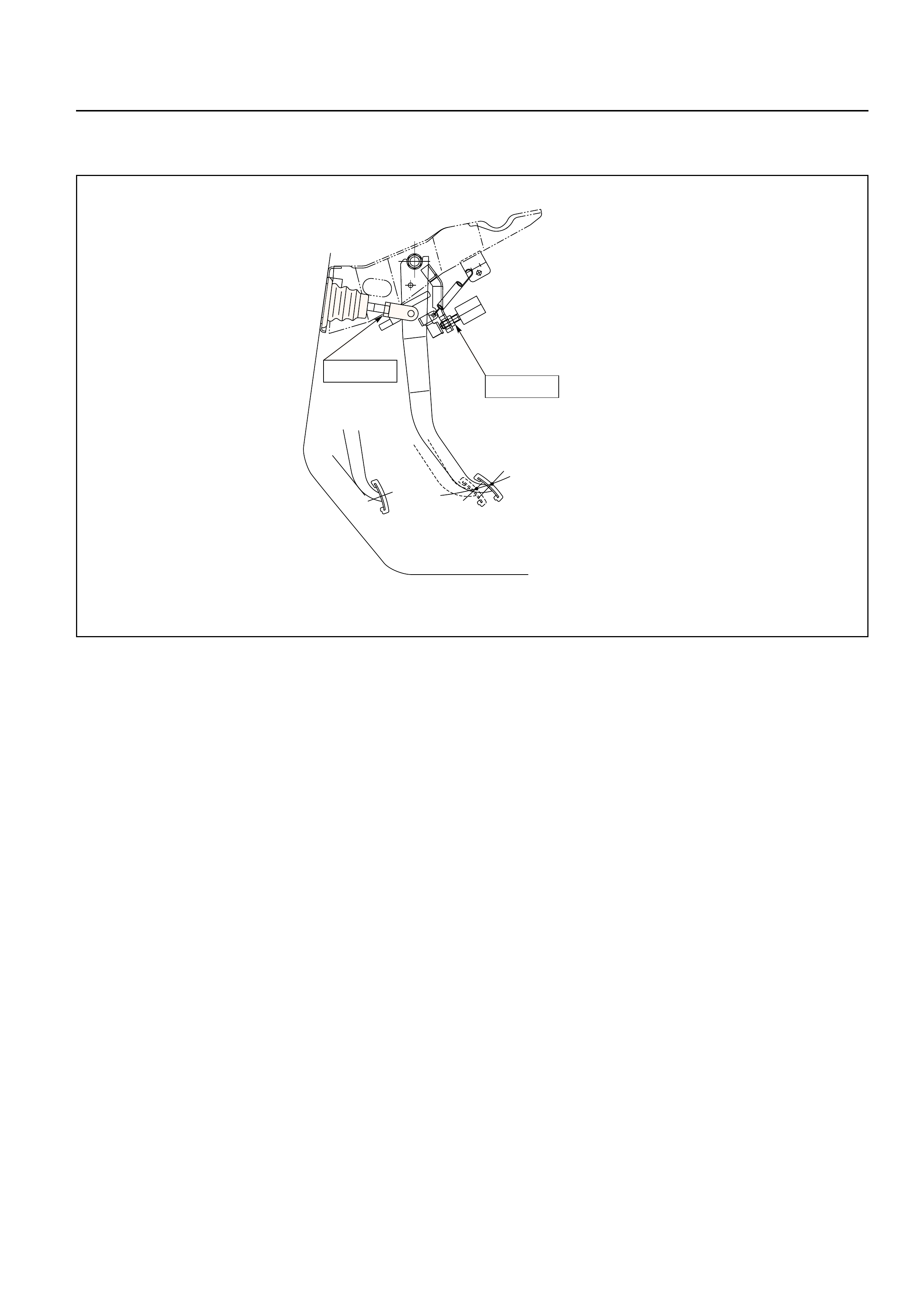
CHECKING BRAKE PEDAL HEIGHT
The push rod serves as the brake pedal stopper when
the pedal is fully released. Brake pedal height
adjustment should be performed as follows:
Adjust Brake Pedal
1. Measure the brake pedal height after making sure
the pedal is fully returned by the pedal return
spring.
Pedal height (L2) must be measured after starting
the engine and revving it several times.
Pedal Free Play (L1) mm (in)
6 – 10 (0.23 – 0.39)
Pedal Height (L2) mm (in)
LHD RHD
208 – 218 211 – 221
(8.19 – 8.58) (8.31 – 8.70)
NOTE:
Pedal free play (L1) must be measured after turning
off the engine and stepping on the brake pedal firmly
five times or more.
2. If the measured value is not within the above
range, adjust the brake pedal as follows:
a) Disconnect the stop light switch connector.
b) Loosen the stop light switch lock nut.
c) Rotate the stop light switch so that it moves
away from the brake pedal.
d) Loosen the lock nut on the push rod.
e) Adjust the brake pedal to the specified height
by rotating the push rod in the appropriate
direction.
f) Tighten the lock nut to the specified torque.
Lock Nut Torque N·m (kg·m/lb·ft)
20 (2.0 / 15)
g) Adjust the stop light switch to the specified
clearance (between switch housing and brake
pedal) by rotating the switch housing.
Clearance mm (in)
0 – 0.2 (0 – 0.008)
NOTE:
While adjusting the installation of the stoplight
switch, make sure that the threaded part of the
stoplight switch does not push the brake pedal.
h) Tighten the stop light switch lock nut.
i) Connect the stop light switch connector.
Switch
Floor panel
(L3)
(A)
(L2)
(L1)
Lock nut
(A)
CHECKING BRAKE PEDAL TRAVEL
1. Pedal height (L3) must be measured after starting
the engine and revving it several times to apply
vacuum to the vacuum booster fully.
NOTE:
Pedal height (L3) must be 100 mm (3.9 in)/85 mm (3.5
in) (LHD/RHD) or more when about 50 kg (110.25 lb)
of stepping force is applied.
2. If the measured value is lower than the above
range, air existing in the hydrauic system is
suspected and perform bleeding procedure.
FRONT AND REAR DISC BRAKE PADS
INSPECTION
Check the outer pad by looking at each caliper from
above. Check the thickness on the inner pad by
looking down through the inspection hole in the top of
the caliper. Whenever the pad is worn to about the
thickness of the pad base, the pad should be removed
for further measurements. The pad should be
replaced anytime the pad thickness (t) is worn to
within 1.0 mm (0.039 in) of the pad itself.
The disc pads have a wear indicator that makes a
noise when the pad wears to where replacement is
required.
Minimum Limit mm (in)
1.0 (0.039)
SERVICING THE FRONT BRAKE ROTOR
In the manufacturing of the front brake rotor, all the
tolerances regarding surface finish, parallelism and
lateral runout are held very closely. The maintenance
of these tolerances provide the surface necessary to
assure smooth brake operation.
LATERAL RUNOUT
Lateral runout is the movement of the rotor from side
to side as it rotates on the spindle. This could also be
referred to as “rotor wobble”.
This movement causes the piston to be knocked back
into its bore. This results in additional pedal travel and
a vibration during braking.
t
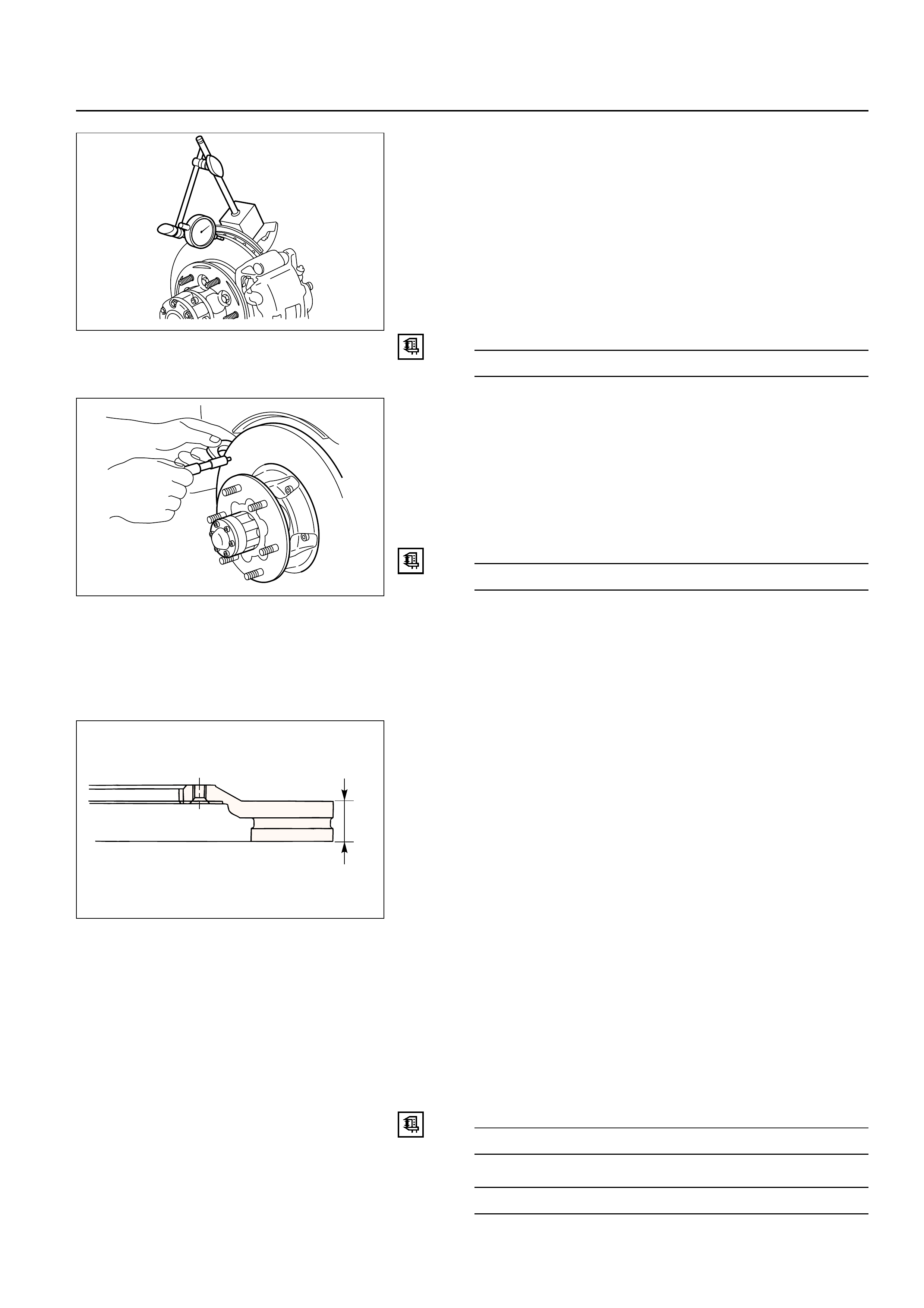
CHECKING LATERAL RUNOUT
1.Adjust the wheel bearing correctly.
•Refer to Front Hub and Disc in Driveline / Axle
Section.
2. Attach a dial indicator to some portion of the
suspension so that the stem contacts the rotor
face about 29 mm (1.14 in) from the rotor edge.
3. Move the rotor one complete rotation.
•The lateral runout should not exceed 0.13 mm
(0.005 in).
Maximum Runout mm (in)
0.13 (0.005)
PARALLELISM
Parallelism is the measurement of the thickness of the
rotor at four or more points around the circumference
of the rotor. All measurement must be made at 29 mm
(1.14 in) from the edge of the rotor.
The rotor thickness must not vary more than 0.010
mm (0.004 in) from point to point.
Maximum Parallelism mm (in)
0.010 (0.0004)
REPLACING FRONT BRAKE ROTORS
When installing new brake rotors, do not refinish the
surfaces. These parts are at the correct level of surface
finish.
REFINISHING FRONT BRAKE ROTORS
Accurate control of the rotor tolerances is necessary
for proper performance of the disc brakes. Machining
of the rotor should be done only with precision
equipment. All brake rotors have a minimum
thickness dimension cast into them. This dimension is
the minimum wear dimension and not a refinish
dimension. The minimum wear dimension is 24.60
mm (0.969 in). The minimum refinish dimension is
24.97 mm (0.983 in).
When refinishing rotors, always use sharp cutting
tools or bits. Dull or worn tools leave a poor surface
finish which will affect initial braking performance.
Vibration dampening attachments should always be
used when refinishing braking surfaces. These
attachments eliminate tool chatter and will result in
better surface finish.
After refinishing, replace any rotor that does not meet
the minimum thickness of 24.97 mm (0.983 in). Do not
use a brake rotor that will not meet the specification.
Minimum Wear Dimension mm (in)
24.60 (0.969)
Refinish Dimension mm (in)
24.97 (0.983)
t
PARALLELSIM
Parallelism is the measurement of the thickness of the
rotor at four or more points around the circumference
of the rotor. All measurements must be made at 22 mm
(0.87 in) from the edge of the rotor.
The rotor thickness must not vary more than 0.010
mm (0.0004 in) from point to point.
Maximum Parallelism Variation mm (in)
0.010 (0.0004)
REPLACING REAR BRAKE ROTORS
When installing new brake rotors, do not refinish the
surfaces. These parts are at the correct level of surface
finish.
REFINISHING REAR BRAKE ROTORS
Accurate control of the rotor tolerances is necessary
for proper performance of the disc brakes. Machining
of the rotor should be done only with precision
equipment. All brake rotors have a minimum
thickness dimension cast into them. This dimension is
the minimum wear dimension and not a refinish
dimension. The minimum wear dimension is 16.60
mm (0.654 in). The refinish dimension is 16.97 mm
(0.668 in).
When refinishing rotors, always use sharp cutting
tools or bits. Dull or worn tools leave a poor surface
finish which will affect initial braking performance.
SERVICING THE REAR BRAKE ROTOR
In the manufacturing of the rear brake rotor, all the
tolerances regarding surface finish, parallelism and
lateral runout are held very closely. The maintenance
of these tolerances provide the surface necessary to
assure smooth brake operation.
LATERAL RUNOUT
Lateral runout is the movement of the rotor from side
to side as it rotates on the spindle. This could also be
referred to as “rotor wobble”.
This movement causes the piston to be knocked back
into its bore. This results in additional pedal travel and
a vibration during braking.
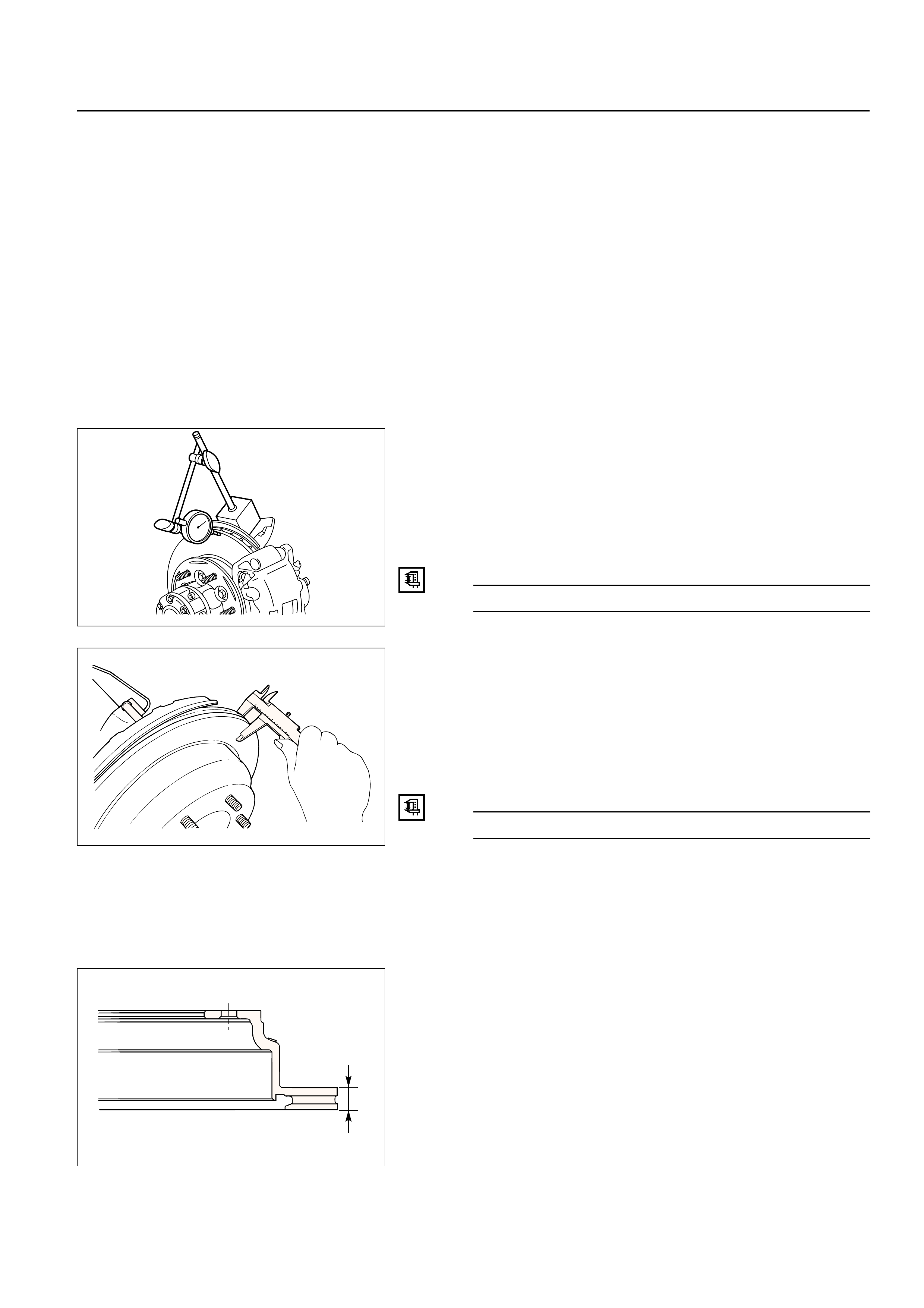
CHECKING LATERAL RUNOUT
1. Attach a dial indicator to some portion of the
suspension so that the stem contacts the rotor
face about 22 mm (0.87 in) from the rotor edge.
2. Move the rotor one complete rotation.
•The lateral runout should not exceed 0.13 mm
(0.005 in).
Maximum Runout mm (in)
0.13 (0.005)
t

Vibration dampening attachments should always be
used when refinishing braking surfaces. These
attachments eliminate tool chatter and will result in
better surface finish.
After refinishing, replace any rotor does not meet the
minimum thickness of 16.97 mm (0.668 in). Do not use
a brake rotor that will not meet the specification.
Minimum Wear Dimension mm (in)
16.60 (0.654)
Refinish Dimension mm (in)
16.97 (0.668)
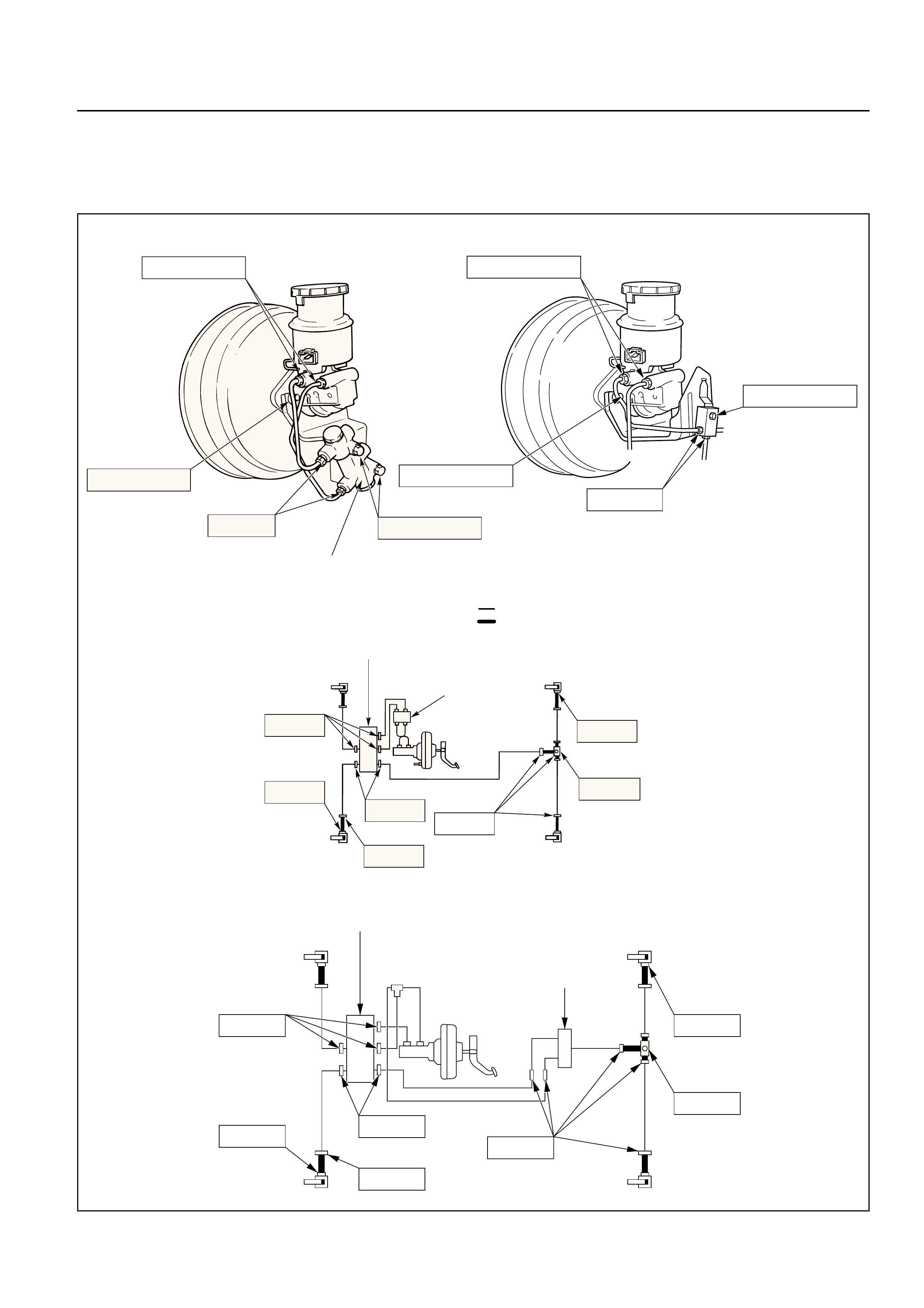
FIXING TORQUE
Brake Hydraulic Lines N·m (kg·m/lb·ft)
12(1.2/104 lb•in)
Brake fluid pipe line
Flexible hose
16(1.6/12)
16(1.6/12)
16(1.6/12)
35(3.5/26)
16(1.6/12) 35(3.5/26)
15(1.5/11)
Hydraulic unit
(Vehicle with ABS only)
P&B valve
(If so equipped)
(Mounting bolt)
13(1.3/113 lb•in)
16(1.6/12) 13(1.3/113 lb•in)
P B Valve(If so equipped)
13 (1.3 / 113 lb in)
13 (1.3 / 113 lb in)
16 (1.6 / 12)
12 (1.2 / 104 lb in)
Vehicle with LSPV
35(3.5/26)
16(1.6/12)
15(1.5/11)
(Mounting bolt)
35(3.5/26)
16(1.6/12)
16(1.6/12)
16(1.6/12)
LSPV
Hydraulic unit
(Vehicle with ABS only)
Brake Pedal N·m (kg·m/lb·ft)
20(2.0/15)
20(2.0/15)
Front and Rear Brakes N·m (kg·m/lb·ft)
74(7.5/54)
Front disc brake
Rear disc brake
35(3.6/26)
74(7.5/54)
155(15.8/115)
35(3.6/26)
104(10.6/77)
44(4.5/32)
8(0.8/69 Ib in)
8(0.8/69 Ib in)

SPECIAL TOOLS
ILLUSTRATION PART NO. PARTNAME
Primary piston holder
5-8840-2306-0 (including master cylinder attach-
(J-39242) ment and master cylinder plug)
5-8840-0277-0 Radiator cap tester
(J-24460-01)
5-8840-2300-0 Push rod gauge
(J-39216)
5-8840-0279-0 Vacuum pump
(J-23738-A)
5-8840-2305-0 Push rod support
(J-39241)
GENERAL DESCRIPTION
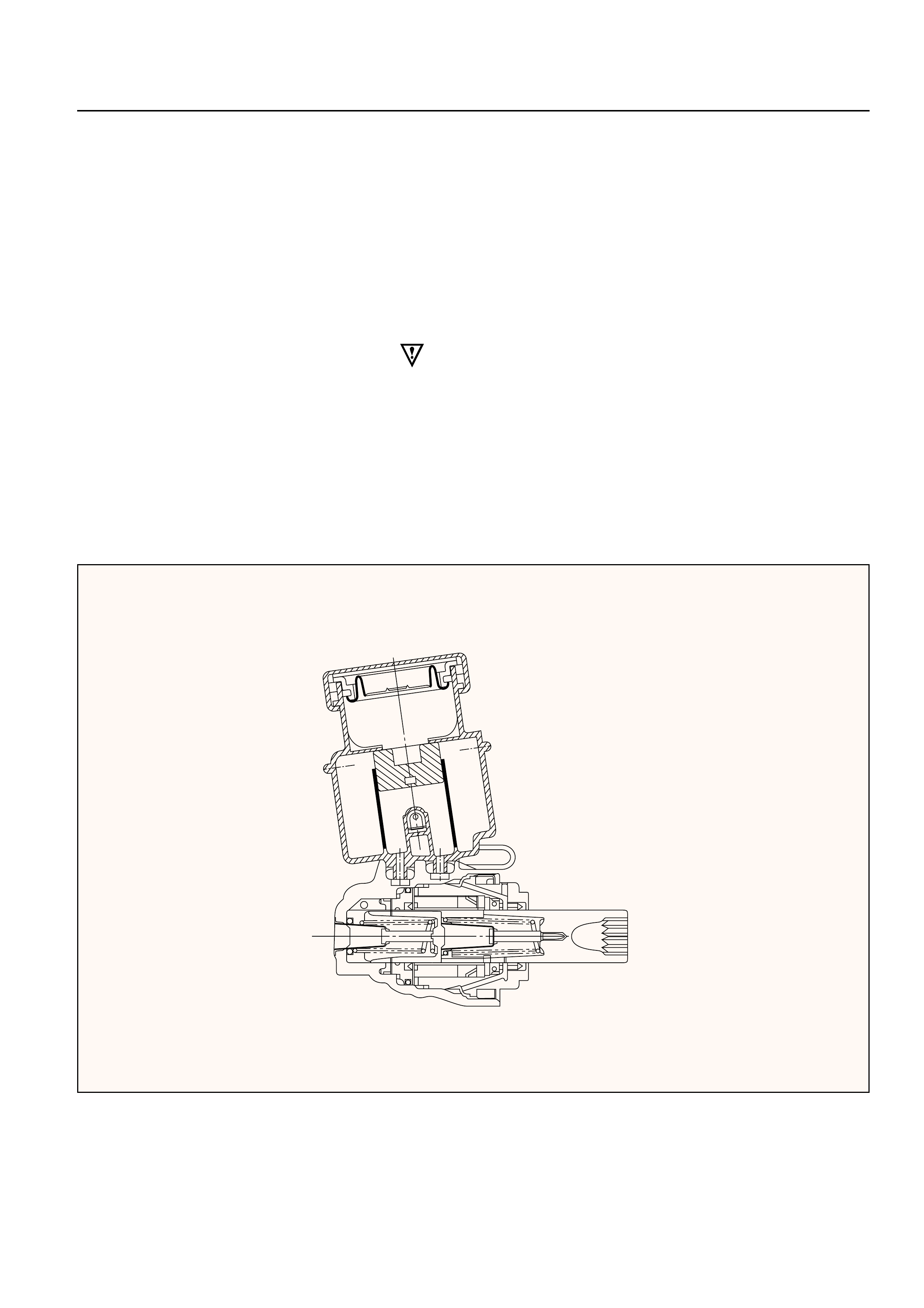
MASTER CYLINDER
The master cylinder contains two pistons that supply
the hydraulic pressure for a dual-circuit braking
system. The primary piston provides the fluid
pressure to the front brakes, while the secondary
piston provides the fluid pressure to the rear brakes.
If the pressure is lost from either system, the
remaining system will function to stop the vehicle.
CAUTION:
1) The master cylinder is not repairable. If found
defective, it must be replaced as complete
assembly.
2) If any hydraulic component is removed or
disconneted, it may be necessary to bleed all or
part of the brake system.
3) The torque values specified are for dry,
unlubricated fasteners.
4) Perform service operations on a clean bench free
from all mineral oil materials.
330RW013

VACUUM BOOSTER
This booster is a tandem vacuum unit with a diaphragm effective diameter 205 mm + 230 mm (gasoline
engine model) / 180 mm + 205 mm (diesel engine model). In normal operating mode, with the service
brakes in the released position, the tandem vacuum booster operates with vacuum on both sides of its
diaphragms. When the brakes are applied, air at atmospheric pressure is admitted to one side of each
diaphragm to provide the power assist. When the service brake is released, the atmospheric air is shut
off from the one side of each diaphragm. The air is then drawn from the booster through the vacuum
check valve to the vacuum source.
CAUTION:
1) If any hydraulic component is removed or disconnected, it may be necessary to bleed all or part of
the brake system.
2) The torque values specified are for dry, unlubricated fasteners.
3) The vacuum booster is not repairable and must be replaced as complete assembly.

DISK BRAKES
The disc brake assembly consists of a caliper, piston, rotor, pad assembly and support bracket. The
caliper assembly has a single bore and is mounted to the support bracket with 2 mounting bolts. The
support bracket allows the caliper to move laterally against the rotor. The caliper is a one-piece casting
with the inboard side containing the piston bore. A square cut rubber seal is located in a groove in the
piston bore which provides the hydraulic seal between the piston and the cylinder wall.
NOTE:
1) Replace all components included in repair kits used to service this caliper.
2) Lubricate rubber parts with clean brake fluid to ease assembly.
3) If any hydraulic component is removed or disconnected, it may be necessary to bleed all or part of
the brake system.
4) Replace pads in axle sets only.
5) The torque values specified are for dry, unlubricated fasteners.
6) Perform service operation a clean bench free from all mineral oil materials.
OPERATION
Hydraulic pressure, created by applying the brake pedal, is converted by the caliper to a stopping force.
This force acts equally against the piston and the bottom of the caliper bore to move the piston outward
and to move (slide) the caliper inward resulting in a clamping action on the rotor. This clamping action
forces the linings against the rotor, creating friction to stop the vehicle.
Front disc brakes
Rear disc brakes
ON-VEHICLE SERVICE
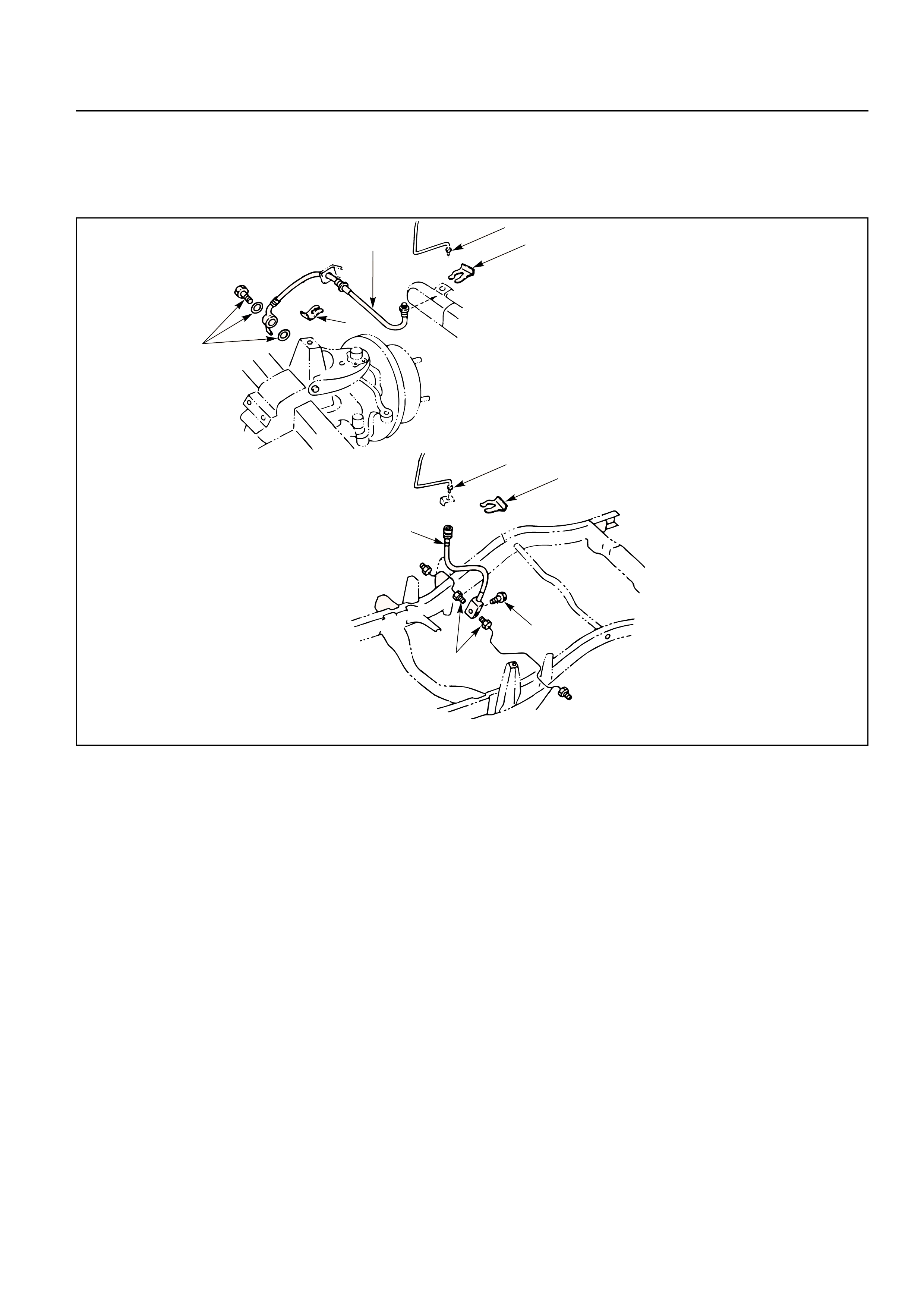
BRAKE HOSE REPLACEMENT
1
2
4
2
3
1
2
4
5
3
Front/Rear Caliper Brake Hose
Removal Steps
1. Brake pipe
2. Clip
3. Bolt and gasket
4. Hose
Installation Steps
To install, follow the removal steps in the
reverse order.
Rear Axle Brake Hose
Removal Steps
1. Brake pipe
2. Clip
3. Brake pipe
4. Bolt
5. Hose
Installation Steps
To install, follow the removal steps in the
reverse order.
REMOVAL
Preparation:
1) Raise the vehicle and support it with suitable
safety stands.
2) Remove wheel and tire assembly.
3) Clean dirt, grease, and other foreign material off
the hose fittings at both ends.
Front/Rear Caliper Brake Hose
1. Brake Pipe
2. Clip
3. Bolt and Gasket
4. Hose
Rear Axle Brake Hose
1. Brake Pipe
2. Clip
3. Brake Pipe
4. Bolt
5. Hose
INSTALLATION
To install, follow the removal steps in the reverse
order, noting the following points. After installing the
brake hoses, bleed brakes as described in this
section.
Front/Rear Caliper Brake Hose
1. Tighten the brake pipes to the specified torque.
Brake Pipe Torque N·m(kg·m/lb·ft)
16 (1.6 / 12)
2. Tighten the bolt to the specified torque.
Bolt Torque N·m(kg·m/lb·ft)
35 (3.5 / 26)
NOTE:
•Always use new copper gaskets.
•Be sure to put the hooked edge of the flexible
hose end into the anti-rotation cavity.
Rear Axle Brake Hose
1. Tighten the brake pipes to the specified torque.
Brake Pipe Torque N·m(kg·m/lb·ft)
16 (1.6 / 12)
2. Tighten the bolt to the specified torque.
Bolt Torque N·m(kg·cm/lb·in)
13 (130 / 113)
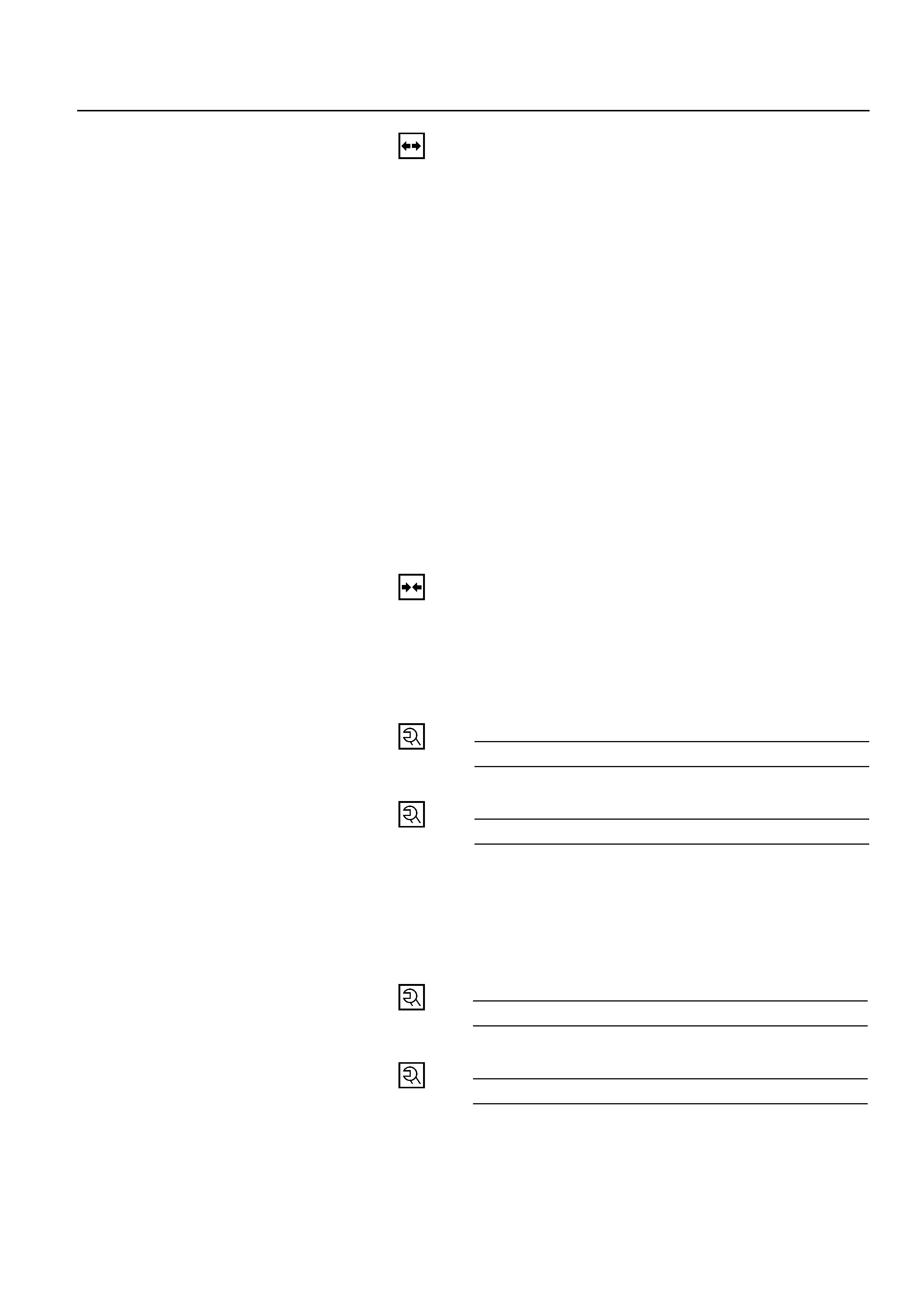
BRAKE PIPE REPLACEMENT
1
1
2
Removal Steps
1. Brake pipe
2. Plastic clip
Installation Steps
To install, follow the removal steps in the
reverse order.
REMOVAL
Preparation:
1) Raise the vehicle and support it with suitable
safety stands.
2) Remove wheel and tire assembly as necessary.
3) Clean dirt, grease, and other foreign material off
the pipe fittings at both ends.
1. Brake Pipe
2. Plastic Clip
1
Vehice with LSPV
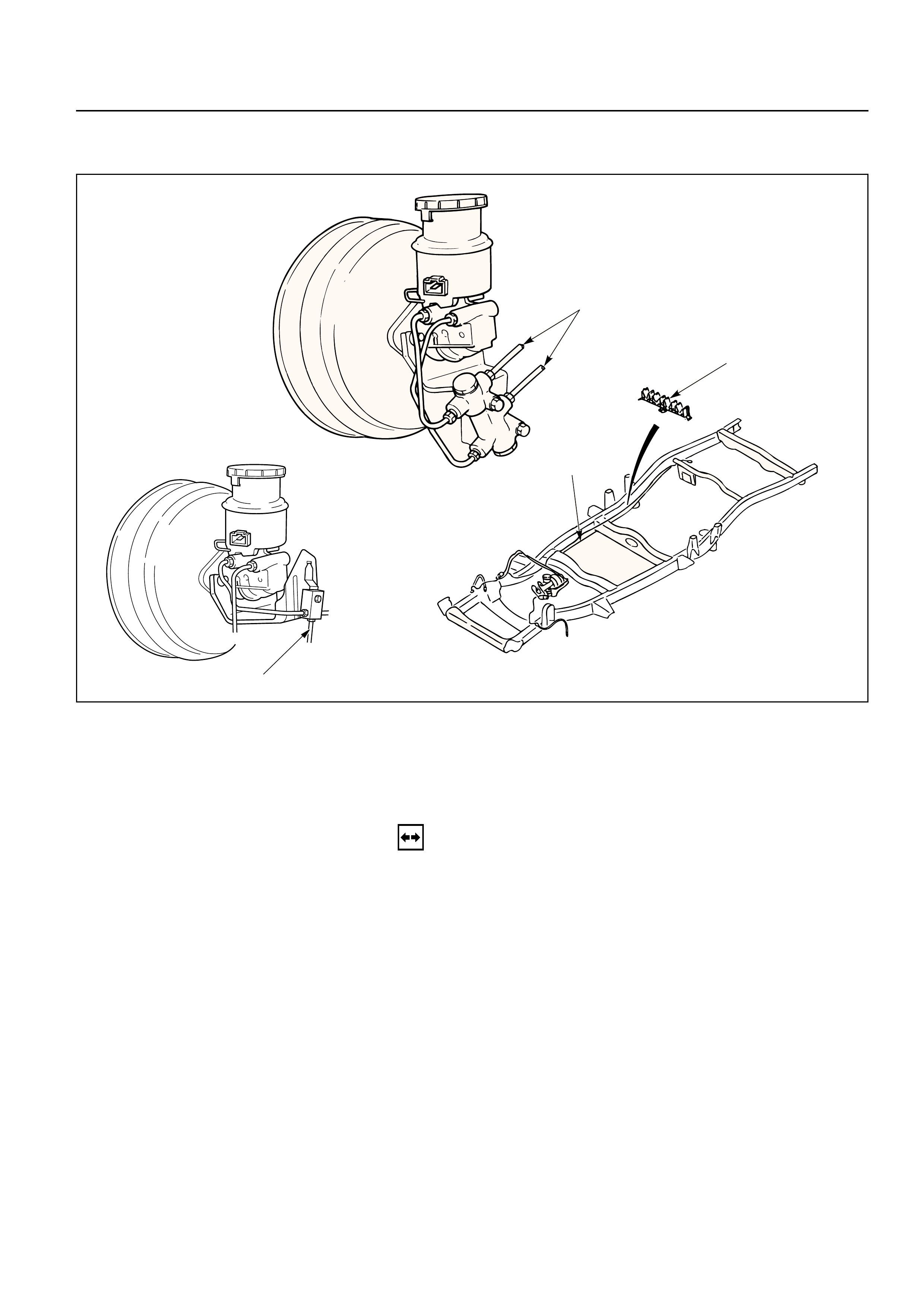
P&B(PROPORTIONING AND BYPASS) VALVE
Master cylinder
(Primary)
Master cylinder
(Secondary)
Rear brake
Front brake
INSTALLATION
To install, follow the removal steps in the reverse
order, noting the following points. After installing the
brake pipes, bleed brakes as described in this section.
1. Tighten the brake pipes to the specified torque.
Brake Pipe Torque N·m(kg·m/lb·ft)
Master Cylinder Side Others
12 (1.2/9) 16 (1.6/12)
The P & B valve contains two sections, each serving a
different function.
The proportioning section of the P & B valve
proportions outlet pressure to the rear brakes after a
predetermined rear input pressure has been reached.
This is done to prevent rear wheel lock-up on the
vehicles with light rear wheel loads.
The valve has a By-bass feature which assures full
system pressure to the rear brakes in the event of a
font brake mulfunction, also full front pressure is
retained in the event of rear brake mulfunction.
The P & B valve is not repairable and must be
replaced as a complete assembly.
P&B VALVE REPLACEMENT
1
3
1
2
Removal Steps
1. Hydraulic pipes
2. Bolt
3. P & B valve
Installation Steps
To install, follow the removal steps in the
reverse order.
REMOVAL
•P & B valve is not repairable and must be
replaced as a complete assembly.
•Care must be taken to prevent brake fluid from
contacting any painted surface.
1. Hydraulic Pipes
•Plug the pipes to prevent the loss of fluid or the
entrance of dirt.
2. Bolt
3. P & B Valve
INSTALLATION
3. P & B Valve
2. Bolt
Bolt Torque N·m(kg·cm/lb·in)
13 (130/113)
1. Hydraulic Pipes
Hydraulic Pipe Torque N·m(kg·m/lb·ft)
16 (1.6/12)
After installing the brake pipes, bleed brakes as
described in Bleeding Brake Hydrauric System this
section.
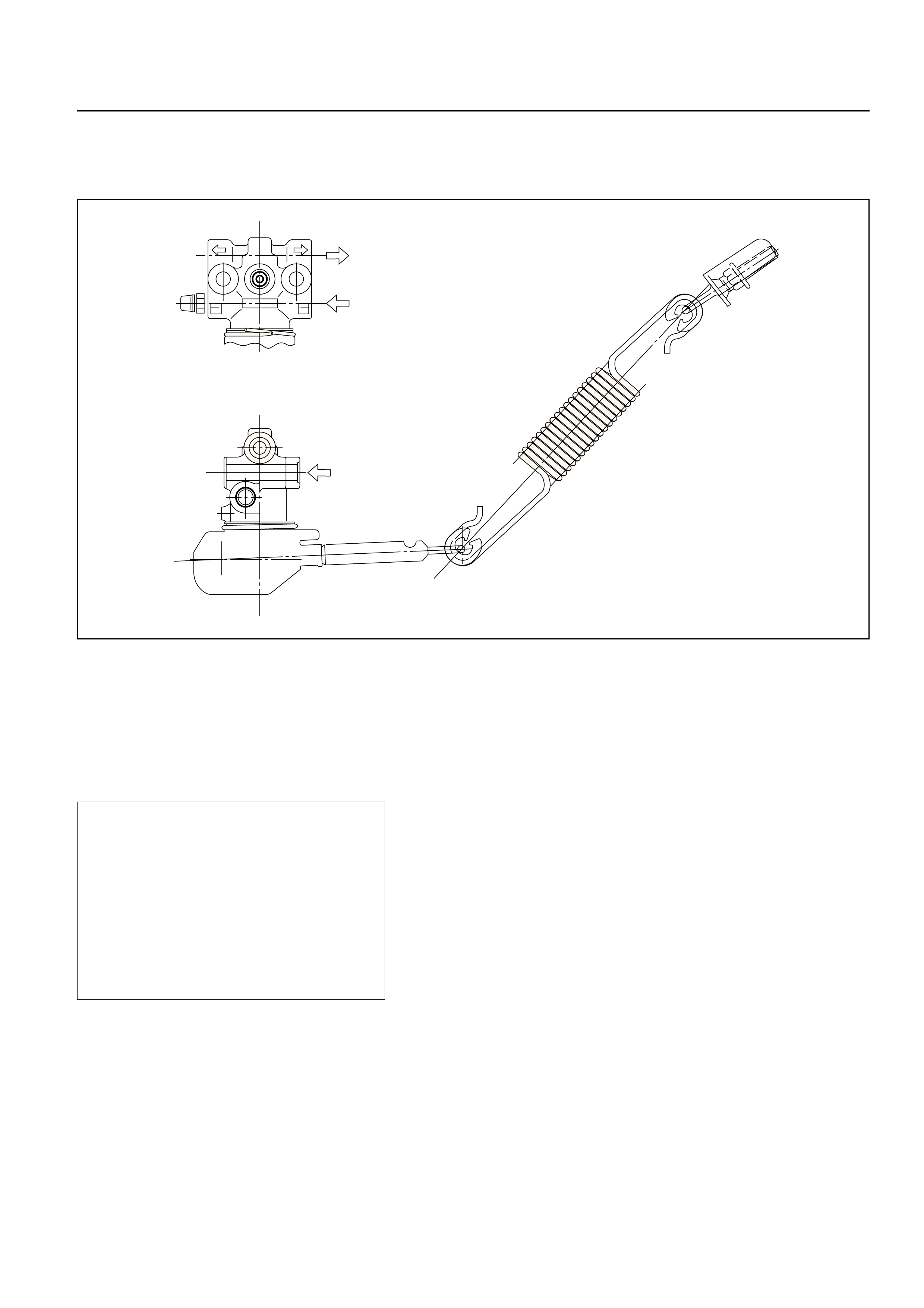
LOAD SENSING PROPORTIONING VALVE (LSPV)
(FOR EUROPE AND SOUTH AFRICA)
to rear wheel cylinder
from front master cylinder
from rear master cylinder
Structure and Operation
The following is an explanation of the structure and
operation of the linkage type load sensing device.
This device controls the fluid pressure to the rear
brakes in accordance with changes in rear axle load
(vertical displacements of the rear axle springs).
•Structure
This device consists of a load sensing lever and a
valve.
The valve is mounted through a bracket to the
frame. One end of the load sensing lever is fixed
to the valve at the frame and the other end to the
rear axle housing through a spring.
F05RW003
•Operation
1) Outline
When the L.S.P.V. (Load Sensing Proportioning
Valve) detects a change in load weight, the load
sensing lever moves. Its reaction force is
transmitted to the bottom of the load sensing
valve to secure an optimum rear wheel cylinder
fluid pressure break point in proportion to the
actual load weight.
Besides, if the front brake system should fail, the
devices is designed to prevent the master cylinder
fluid pressure from decreasing and to apply it
directly to the rear wheel cylinder to obtain a
sufficient braking performance.
From rear
master cylinder
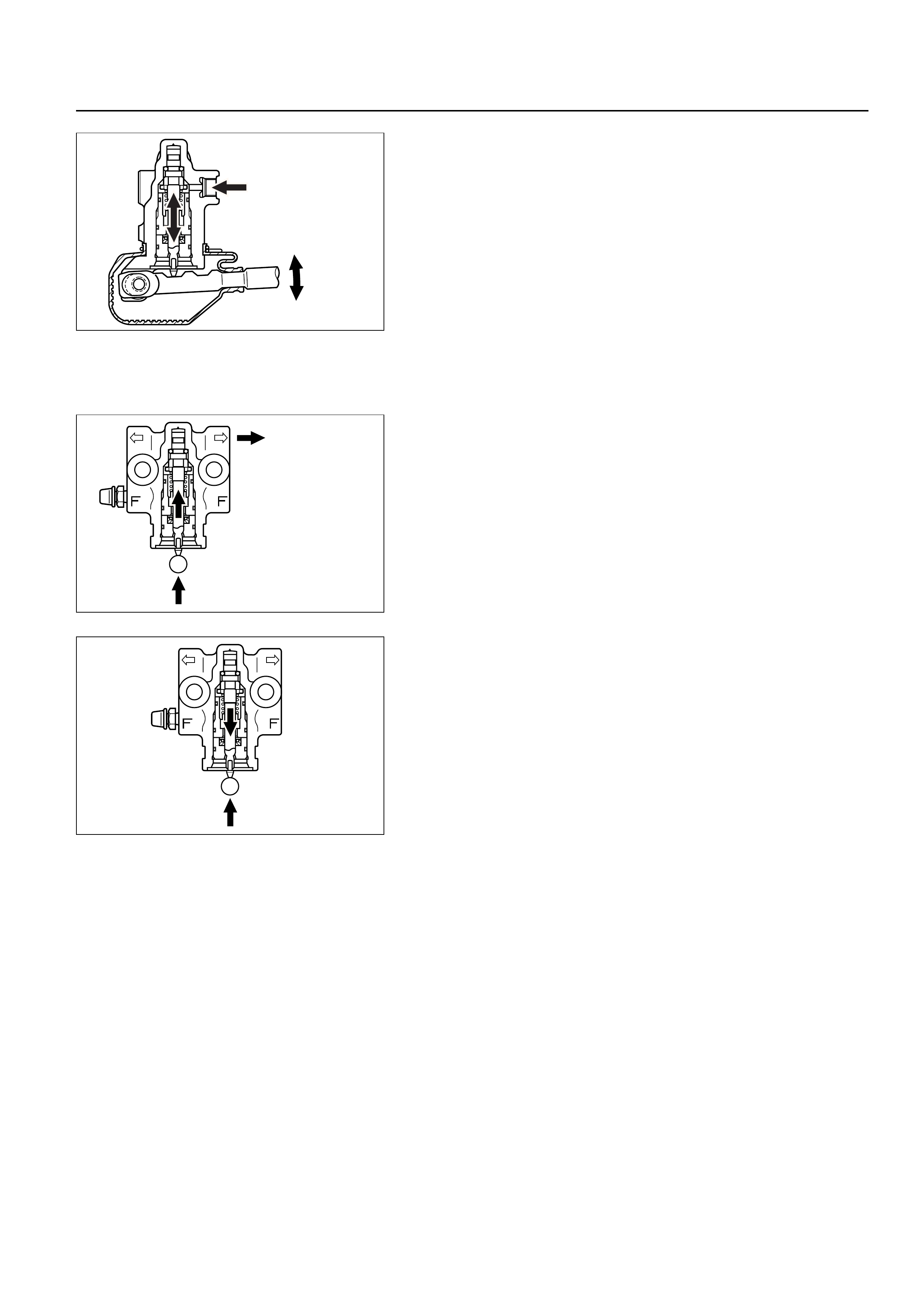
2) Operation
(1) When the fluid pressure is under the break point.
The fluid pressure of the rear master cylinder
passes through a clearance between the valve
seal and the piston and acts on the rear wheel
cylinder. At this moment, a downward force is
applied to the piston. However, the compression
spring force and reaction force of the load sensing
lever keep the piston in the upper position by
pushing upwards. (See the left figure.)
To rear
wheel cylinder
(2) When the fluid pressure is equal to the break
point.
As the rear wheel cylinder pressure increases, it
surpasses the compression spring force and
reaction force of the load sensing lever, causing
the pistion to move downwards, so that the
pistion butts against the valve seal to shut off the
fluid line between the master cylinder and rear
wheel cylinder. (See the left figure.)
(3) When the fluid pressure is over the break point.
When the fluid pressure increases further, the
piston moves upwards. The moment the piston
comes apart from the valve seal, fluid pressure is
applied to the rear wheel cylinder and the piston
moves downwards so that the fluid line is shut off
again. This process goes on repeatedly to control
the fluid pressure to the rear wheel cylinder.
C05RW024
C05RW021
C05RW025
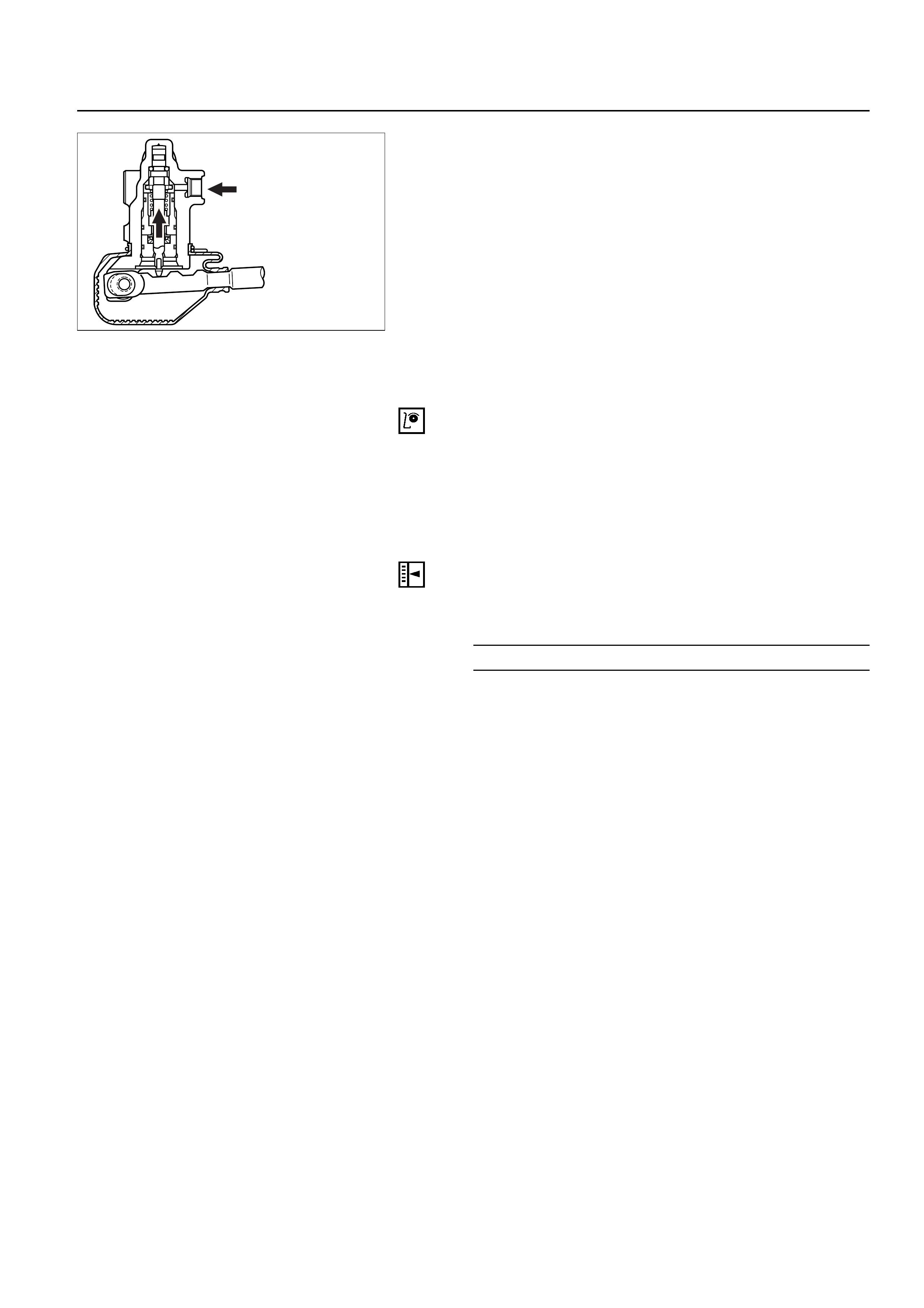
(4) When the front brake system fails.
When there is a failure in the front brake system,
the fluid pressure from the front master cylinder
decreases. As a result, the balance between the
front and rear brake side fluid pressures is lost at
the control valve sleeve so that the control valve
sleeve moves upwards.
The control valve sleeve strikes against the piston,
thereby pushing the piston upwards.
Accordingly, the fluid pressure of the rear master
cylinder is not decreased and is applied directly to
the rear wheel cylinder to secure a sufficient
braking performance of the rear brakes. (See the
left figure.)
Valve Maintenance
In the case of fluid leak or other abnormalities, faulty
valve should be replaced.
Note:
The load sensing proportioning valve is not
repairable and must be replaced as a complete
assembly.
ADJUSTMENT PROCEDURE OF LSPV
1. Adjust the rear axle weight by loading the
laggage compartmemt as necessary.
Rear Axle Weight N (kg / lb)
10,300 (1,050 / 2,315)
Note:
The rear axle weight should be adjusted to the
specified value with a man seated in the driver seat.
Rear master cylinder
fluid Pressure
C05RW022
2. Check the rear wheel cylinder fluid pressure.
Install the pressure gauge on bleeder screws on
the front and rear brakes.
a. Depress the brake pedal slowly until the front
wheel cylinder fluid pressure reaches 7845 kPa
(80 kg/cm2/ 114 psi)
Note:
• The brake pedal should be depressed
gradually until specified pressure is reached
without pumping or adjusting foot pressure.
• If the front wheel cylinder fluid pressure rises
abobe 7845 kPa (80 kg/cm2/ 114 psi), release
the pedal fully, then depress the pedal again.
b. Hold the front wheel cylinder fluid pressure at
7845 kPa (80 kg/cm2/ 114 psi) for 2 seconds,
check the rear wheel cylinder fluid pressure.
Rear wheel cylinder
fluid pressure kPa (kg/cm2/ psi)
6374±539 (65±5.5 / 924±78)
c. If the rear wheel cylinder fluid pressure is not
within the specified range, adjust the fluid
pressure.
3. Adjust the rear wheel cylinder fluid pressure.
The fluid pressure can be adjusted by the bolt
projection (1) or bolt projection (2).
a. If the fluid pressure is lower than specified
range, increase the dimention (1) or (2).
b. If the fluid pressure is higher than the specified
range, decrease the dimention (1) or (2).
Reference:
Dimention (1): The fluid pressure can be
adjusted about 196 kPa (2
kg/cm2/ 28 psi) by one turning
of the nut.
Dimention (2): The fluid pressure can be
adjusted about 98 kPa (1 kg/cm2
/ 14 psi) by sliding the bolt
position (per 1 mm / 0.039 in).
4. Check the rear wheel cylinder fluid pressure.
If the rear wheel cylinder fluid pressure is not
within the specified range, try the adjustment
again.
5. Bleed the brake hydraulic line and check the fluid
leak.
2
1
C05RW023
BRAKE PEDAL REPLACEMENT
10 9
5
12
4
2
7
8
6
11
3
1
M/T
Removal Steps
1. Shift knob
2. Front console assembly
3. Lower cluster assembly
4. Instrument panel driver lower cover
assembly
5. Anti-theft controller
6. Stoplight switch connector
7. Return spring
8. Snap pin
9. Pin
10. Nut
11. Pin, fulcrum
12. Brake pedal
Installation Steps
12. Brake pedal
11. Pin, fulcrum
10. Nut
9. Pin
8. Snap pin
7. Return spring
6. Stoplight switch connector
5. Anti-theft controller
4. Instrument panel driver lower cover
assembly
3. Lower cluster assembly
2. Front console assembly
1. Shift knob
This illustration is based on the LHD model.
REMOVAL
1.Shift Knob
2.Front Console Assembly
3.Lower Cluster Assembly
4.Instrument Panel Driver Lower Cover Assembly
5.Anti-theft Controller
6.Stoplight switch Connector
7.Return Spring
8.Snap Pin
9.Pin
10.Nut
11.Pin, Fulcrum
12.Brake Pedal
INSTALLATION
12.Brake Pedal
11.Pin, Fulcrum
•Apply grease to the entire circumference of the
fulcrum pin.
10.Nut
Bolt and Nut TorqueN·m (kg·m / lb·ft)
33 (3.3 / 24)
9.Pin
•Apply grease to the entire circumference of the
push rod pin.
8.Snap Pin
•Adjust pedal free travel. Refer to “Brake Pedal
Adjustment” previously in this section.
7. Return Spring
6. Stoplight Switch Connector
5. Anti-theft Connector
4. Instrument Panel Driver Lower Cover Assembly
3. Lower Cluster Assembly
2. Front Console Assembly
1. Shift Knob
STOPLIGHT SWITCH REPLACEMENT
67
5
42
3M/T
1
Removal Steps
1. Shift Knob
2. Front Console Assembly
3. Lower Cluster Assembly
4. Instrument Panel Driver Lower Cover
Assembly
5. Stoplight Switch Connector
6. Lock Nut
7. Switch
Installation Steps
7. Switch
6. Lock Nut
5. Stoplight Switch Connector
4. Instrument Panel Driver Lower Cover
Assembly
3. Lower Cluster Assembly
2. Front Console Assembly
1. Shift Knob
REMOVAL
1. Shift Knob
2. Front Console Assembly
3. Lower Cluster Assembly
4. Instrument Panel Driver Lower Cover Assembly
5. Stoplight Switch Connector
6. Lock Nut
7. Switch
This illustration is based on the LHD model.
INSTALLATION
7. Switch
•Adjust the stoplight switch to the specified
clearance (between switch housing and brake
pedal) by rotating the switch housing.
Clearance mm (in)
0 – 0.2 (0 – 0.008)
NOTE:
While adjusting the installation of the stoplight
switch, make sure that the threaded part of the
stoplight switch does not push the brake pedal.
6. Lock Nut
5. Stoplight Switch Connector
4. Instrument Panel Driver Lower Cover Assembly
3. Lower Cluster Assembly
2. Front Console Assembly
1. Shift Knob
(A)
FLUID RESERVOIR TANK
2
4
1
3
Removal Steps
1. Electrical connector
2. Retainer
3. Fluid reservoir
4. O-ring
Installation Steps
To install, follow the removal steps in the
reverse order.
REMOVAL
NOTE:
Before removing fluid reservoir, remove brake fluid
from fluid reservoir.
1. Electrical Connector
2. Retainer
3. Fluid Reservoir
•The fluid level sensor is built into the fluid
reservoir. It cannot be removed for servicing.
4. O-ring
INSTALLATION
To install, follow the removal steps in the reverse
order, noting the following points;
4. O-ring
•O-ring must be set onto the fluid reservoir, before
installing fluid reservoir.
Retainer
Fluid reservoir
O-ring
MASTER CYLINDER ASSEMBLY
6
2
1
5
3
4a
4b
Removal Steps
1. Electrical connector
2. Brake pipes
3. 2 attaching nuts
4a. P&B valve and bracket
4b. 3-way connector and bracket (Vehicle
with LSPV only)
5. Master cylinder
6. Spacer and 2 gaskets
Installation Steps
To install, follow the removal steps in the
reverse order.
This illustration is based on the LHD model.
330RW015
REMOVAL
CAUTION:
When removing master cylinder from vacuum
booster, be sure to get rid of the internal negative
pressure of the vacuum booster (by, for instance,
disconnecting vacuum hose) in advance.
If any negative pressure remains in the vacuum
booster, the piston may possibly come out when the
master cylinder is being removed, letting the brake
fluid run out.
While removing master cylinder, further, do not hold
the piston as it can be easily pulled out.
Outside surface of the piston is the surface on which
seals are to slide. Care should be taken to keep the
surface free of cuts and dents.
1.Electrical Connector
2.Brake Pipes
•After disconnecting the brake pipe, cap or tape
the openings of the brake pipe to prevent the
entry of foreign matter.
3.2 Attaching Nuts
4a.P&B Valve and Bracket
4b.3-way Connector and Bracket (Vehicle with LSPV
Only)
5.Master Cylinder
6.Spacer and 2 Gaskets
INSTALLATION
6.Spacer and 2 Gaskets
5.Master Cylinder
•When replacing the master cylinder or vacuum
booster or both, always measure the vacuum
booster push rod protrusion and adjust it as
necessary. (Refer to Vacuum Booster Assembly in
this section.)
4a.P & B Valve and Bracket
4b.3-way Connector and Bracket (Vehicle with LSPV
Only)
3. 2 Attaching Nuts
•Tighten the attaching nuts to the specified torque.
Attaching Nut Torque N·m (kg·cm / lb·in)
13 (130 / 113)
2. Brake Pipes
•Tighten the brake pipe to the specified torque.
Brake Pipe Torque N·m (kg·m / lb·ft)
Master Cylinder Side Others
12 (1.2 / 9) 16 (1.6 / 12)
1. Electrical Connector
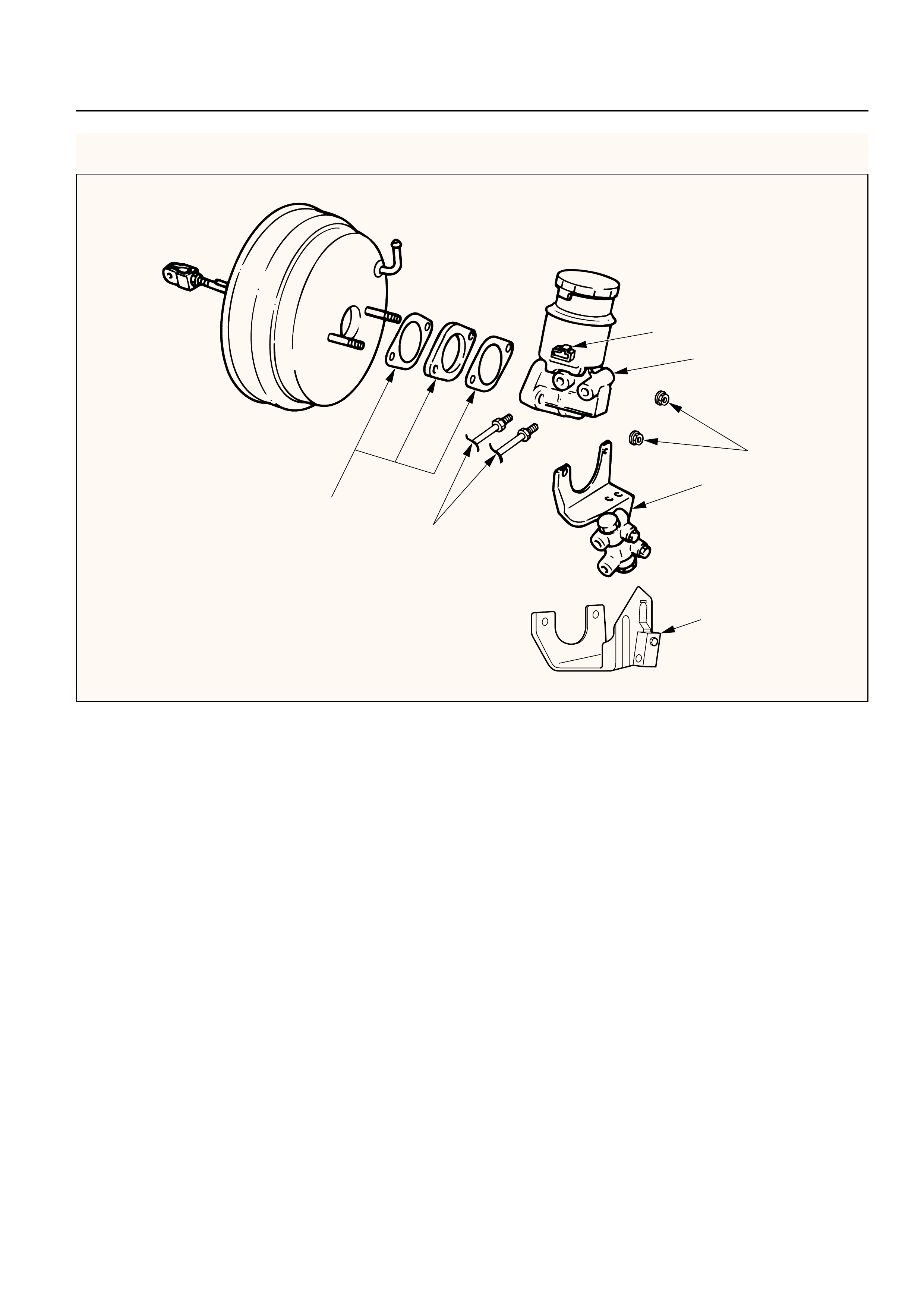
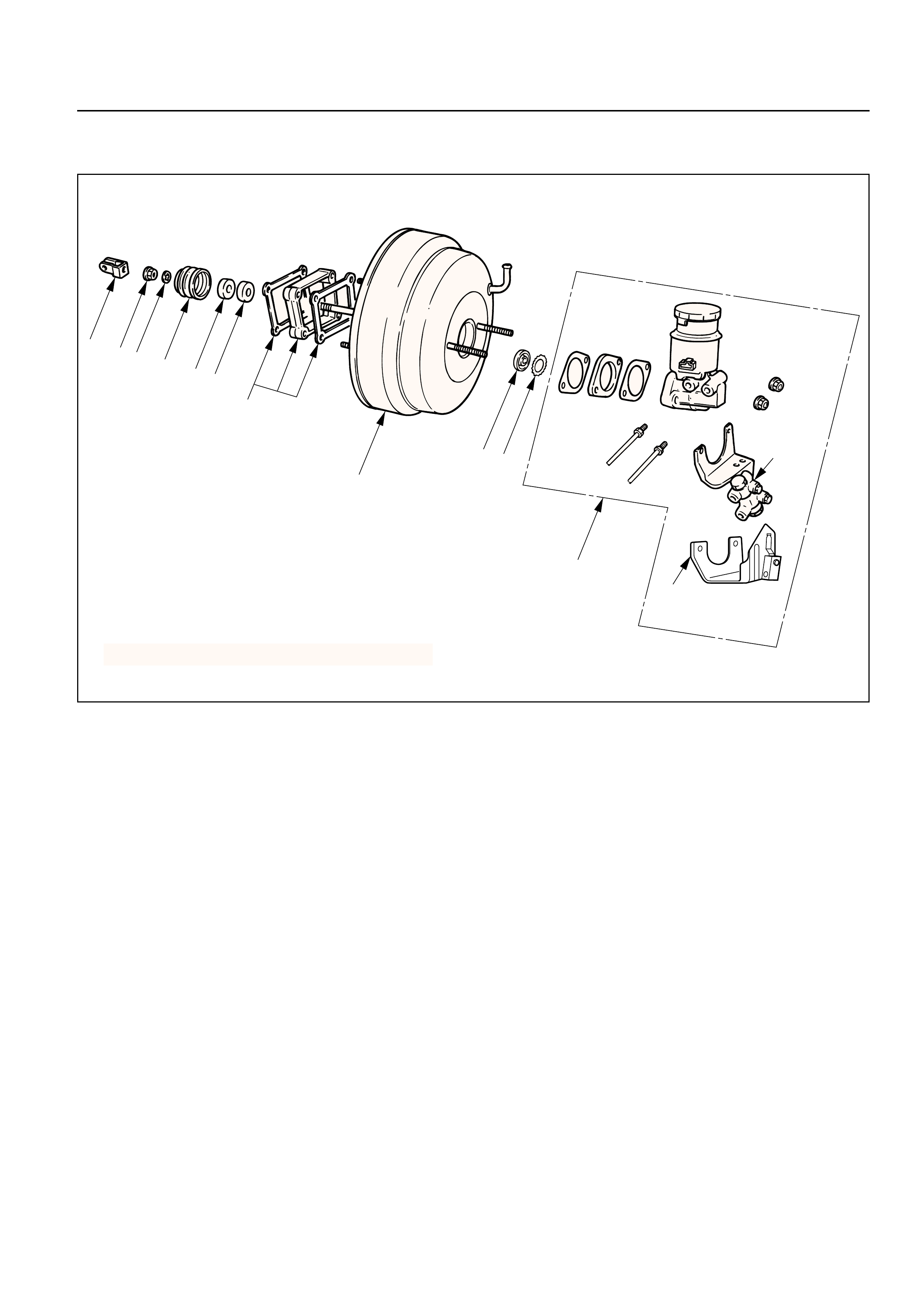
VACUUM BOOSTER ASSEMBLY
1
P&B valve
equipped
vehicle
LSPV
equipped
vehicle
2
4
3
3
5
Removal Steps
1. Master cylinder
2. Vacuum hose
3. Yoke clevis
4. Vacuum booster fixing nut
5. Vauum booster
Installation Steps
To install, follow the removal steps in the
reverse order.
This illustration is based on the LHD model.
331RW010
REMOVAL
•Before removing the vacuum booster assembly,
disconnect and remove brake pipes.
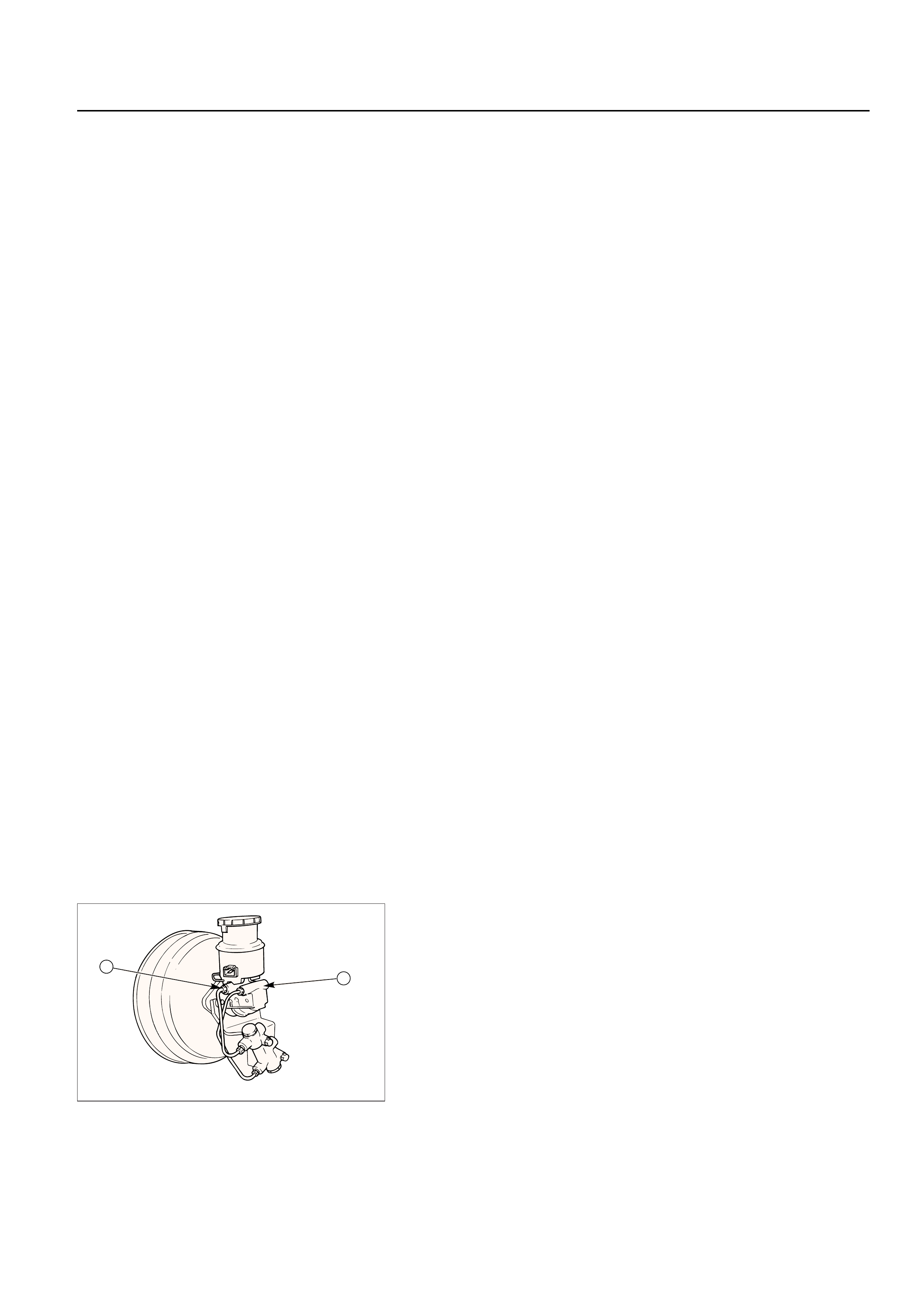
1.Master Cylinder
•Refer to Master Cylinder Assembly in this Section.
CAUTION:
When removing master cylinder from vacuum booster,
be sure to get rid of the internal negative pressure of
the vacuum booster (by, for instance, disconnecting
vacuum hose) in advance.
If any negative pressure remains in the vacuum
booster, the piston may possibly come out when the
master cylinder is being removed, letting the brake
fluid run out.
While removing master cylinder, further, do not hold
the piston as it can be easily pulled out.
Outside surface of the piston is the surface on which
seals are to slide. Care should be taken to keep the
surface free of cuts and dents.
2. Vacuum Hose
3. Yoke Clevis
•Disconnect the yoke clevis from the brake pedal.
4. Vacuum Booster Fixing Nut
5. Vacuum Booster
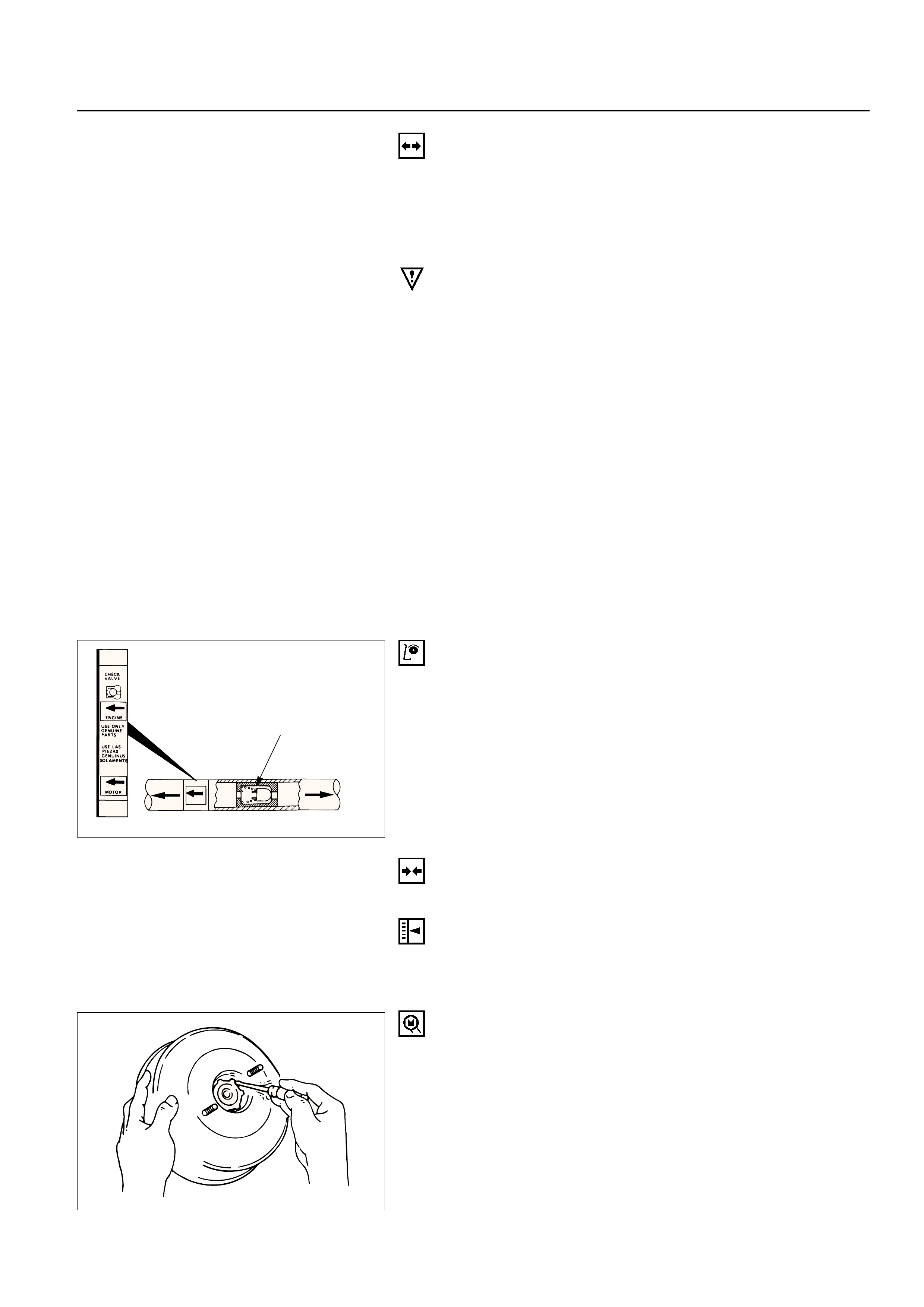
INSPECTION AND REPAIR
Vacuum Hose
Inspect the check valve, which is installed inside the
vacuum hose.
1) Air should pass freely from the vacuum booster to
the engine.
2) Air should not pass from the engine to the
vacuum booster. If it does, the check valve is
inoperative and must be replaced.
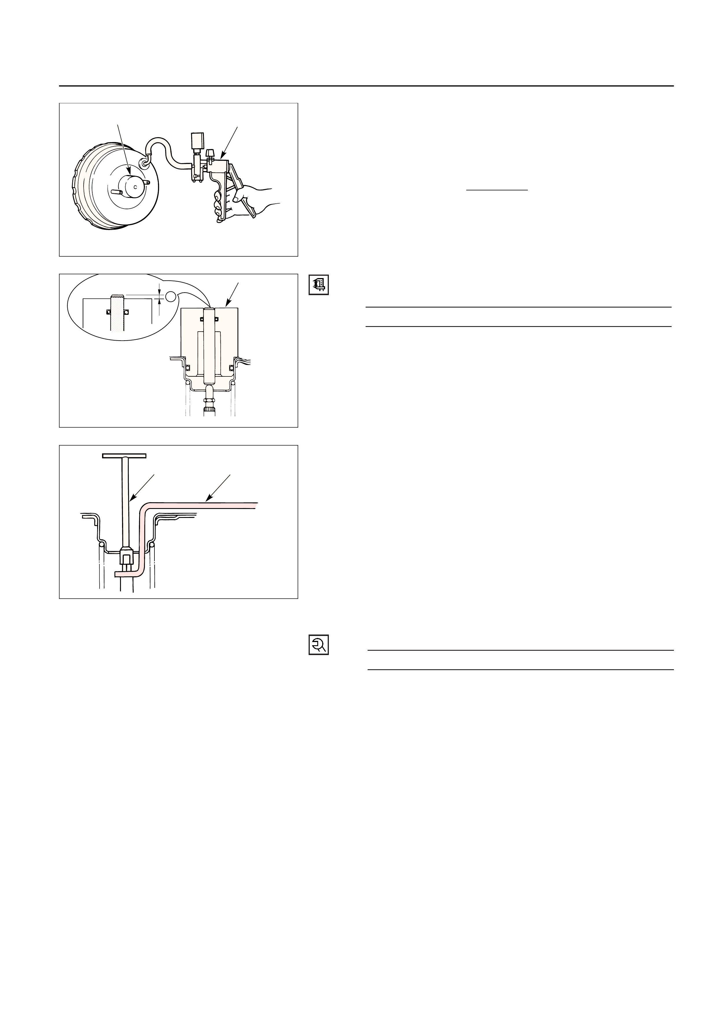
INSTALLATION
5. Vacuum Booster
Vacuum booster push rod adjustment.
NOTE:
When replacing either master cylinder or vacuum
booster, be sure to measure push rod, and adjust
required.
Push rod gauge: 5-8840-2300-0 (J-39216)
Vacuum pump: 5-8840-0279-0 (J-23738-A)
Push rod support: 5-8840-2305-0 (J-39241)
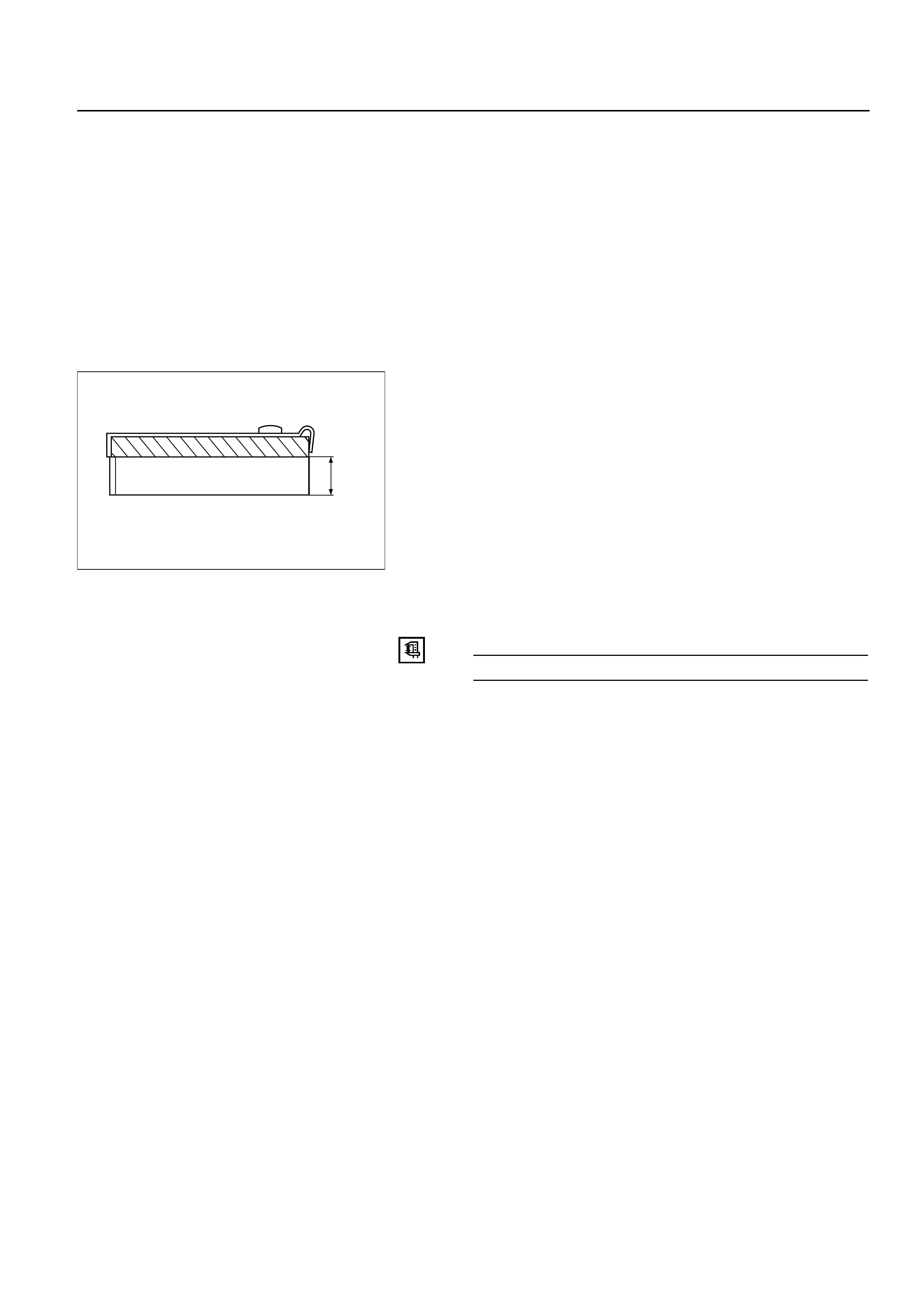
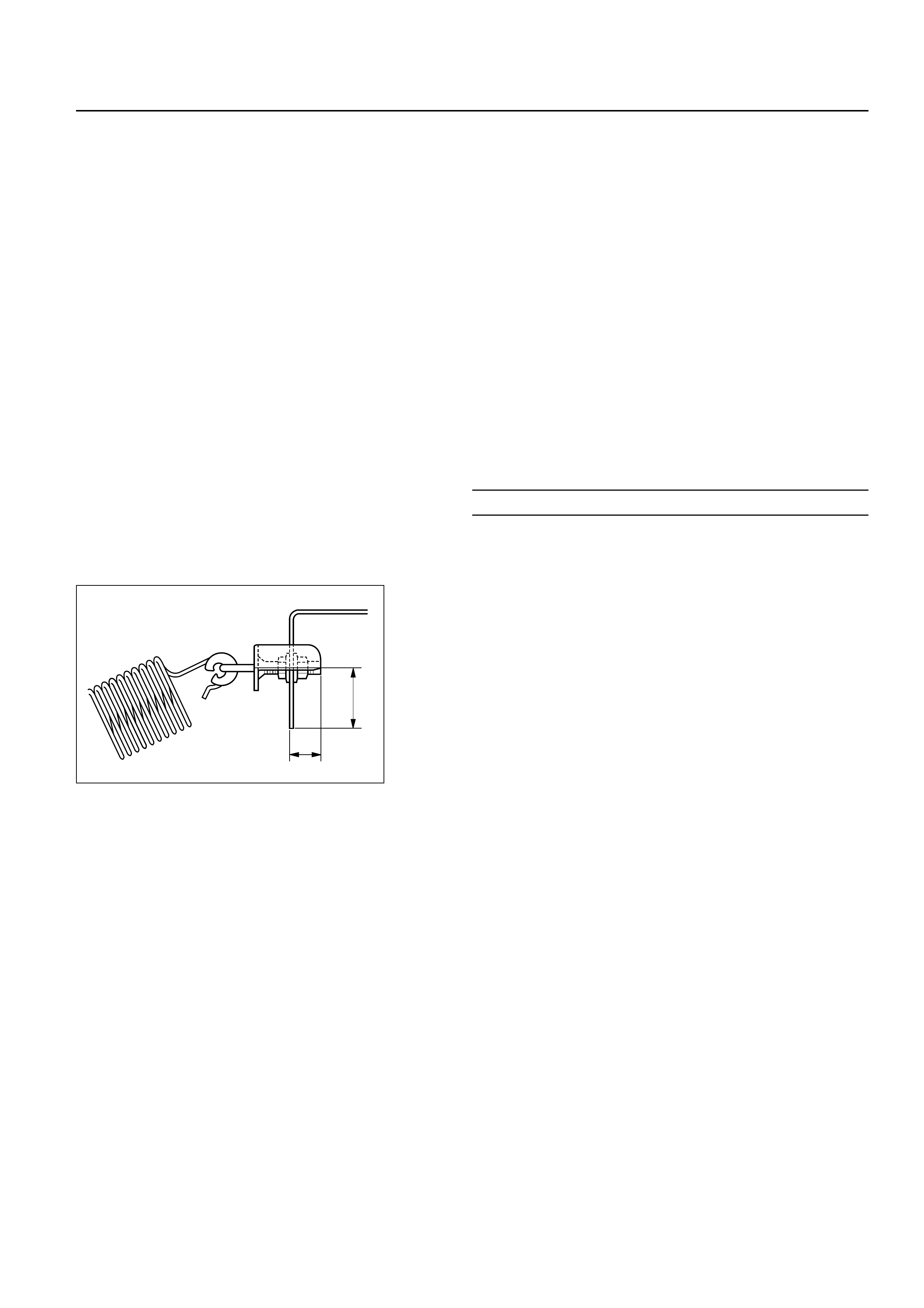
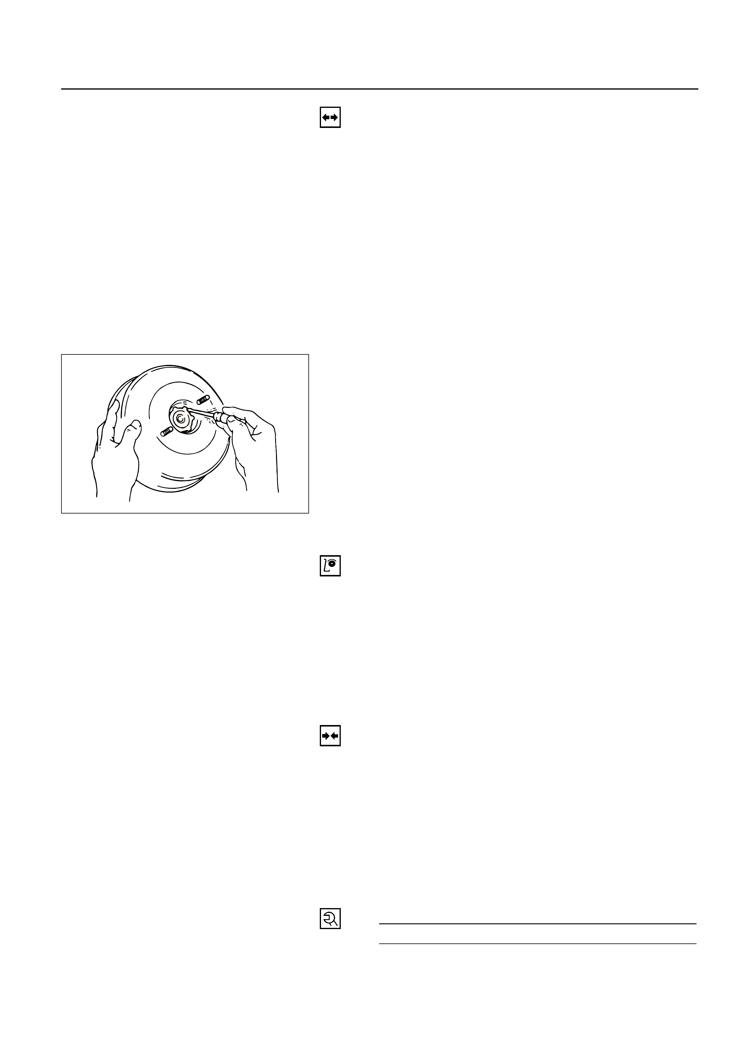
1) Remove retainer from vacuum booster front shell
using a small screwdriver. Then gently draw plate
and seal assembly out of the shell inside.
Check valve
To Engine To Vacuum servo
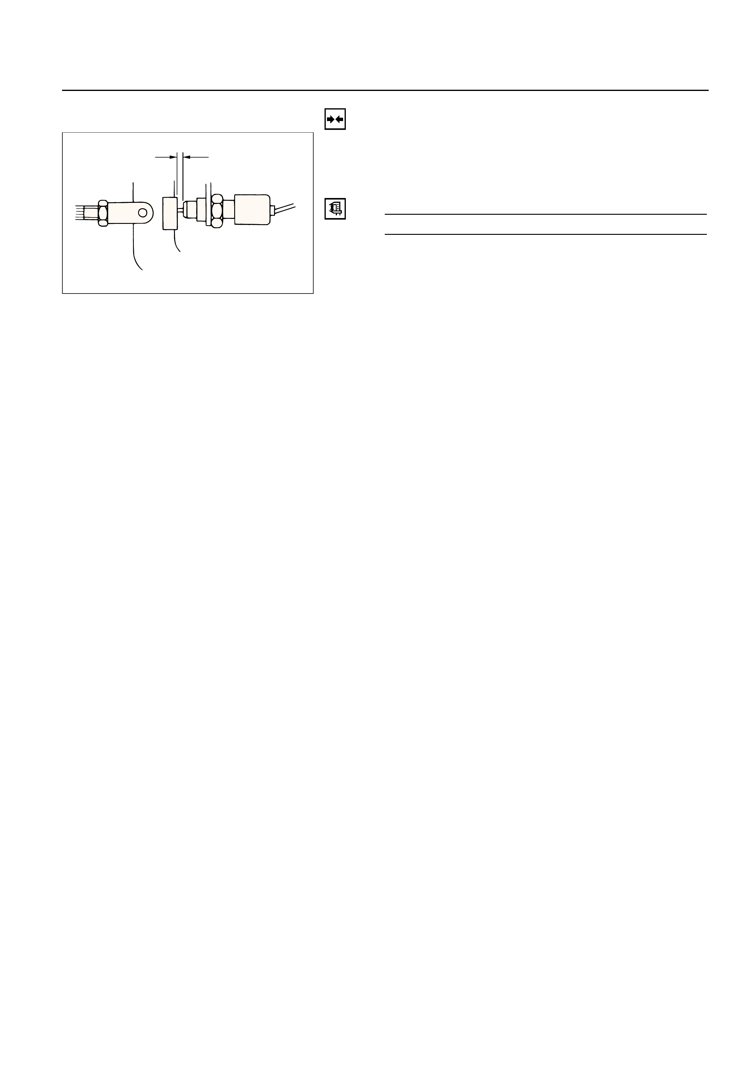
2)Set push rod gauge on vacuum booster, and
apply negative pressure by means of vacuum
pump so that the pressure in the vacuum booster
becomes 500 mm Hg.
NOTE:
Be sure to apply. NEGATIVE pressure after installing
a push rod gauge on vacuumbooster.
3)Measure dimension L
Dimension L(Standard)mm
0 ±0.1
5-8840-0279-0
5-8840-2300-0
L
5-8840-2300-0
4)If dimension Lis out of the standard range,
adjust push rod using the special tool.
5)Mount plate and seal assembly in vacuum
booster front shell. Then install retainer.
4.Vacuum Booster Fixing Nut
Vacuum Booster Fixing Nut TorqueN·m (kg·m / lb·ft)
21 (2.1 / 16)
3.Yoke Clevis
2.Vacuum Hose
•In case of the gasoline engine model, make sure
that the arrow on the hose points in the direction of
the engine.
1.Master Cylinder
•Refer to Master Cylinder Assembly in this Section.
5-8840-2305-0
T-wrench
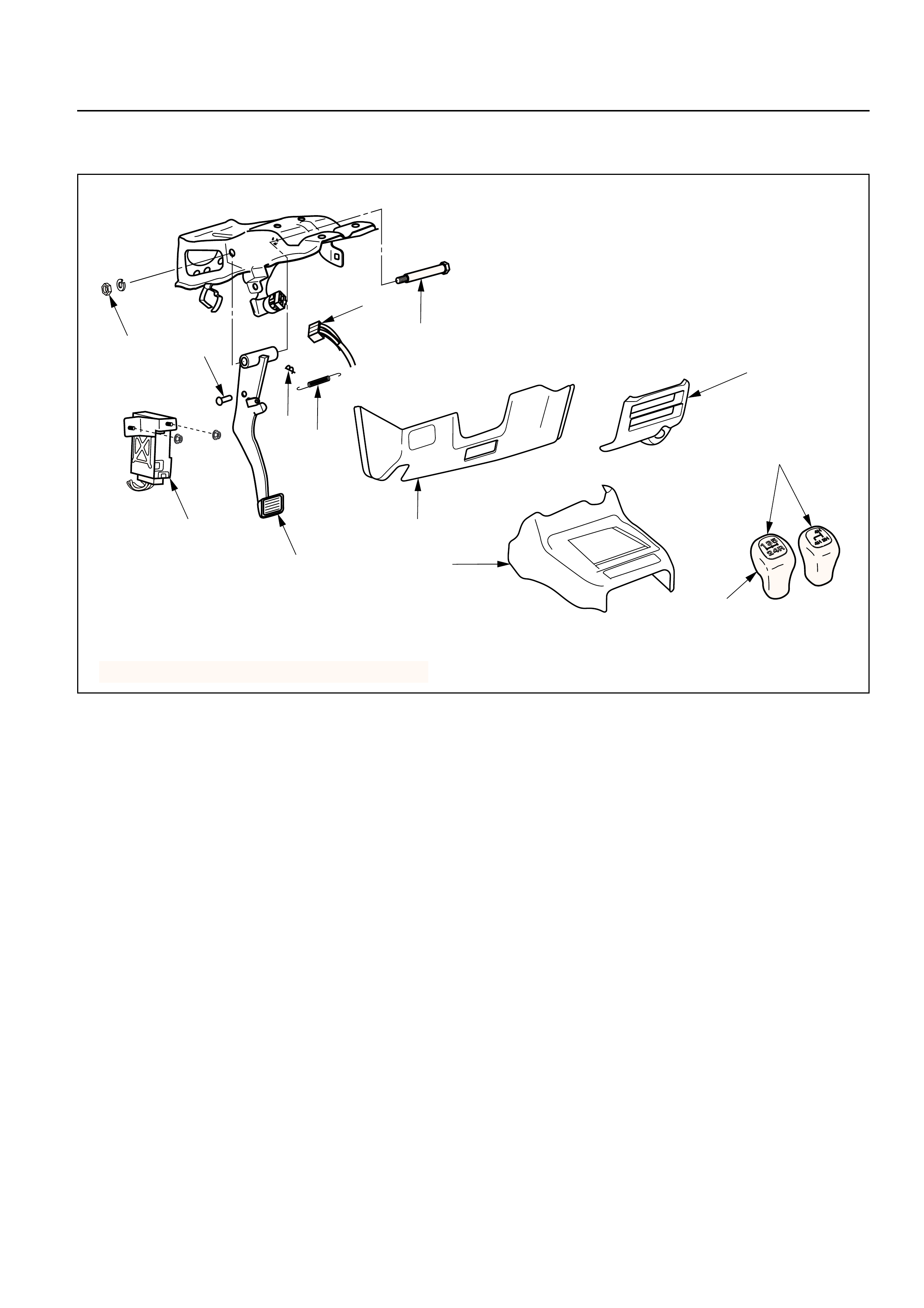
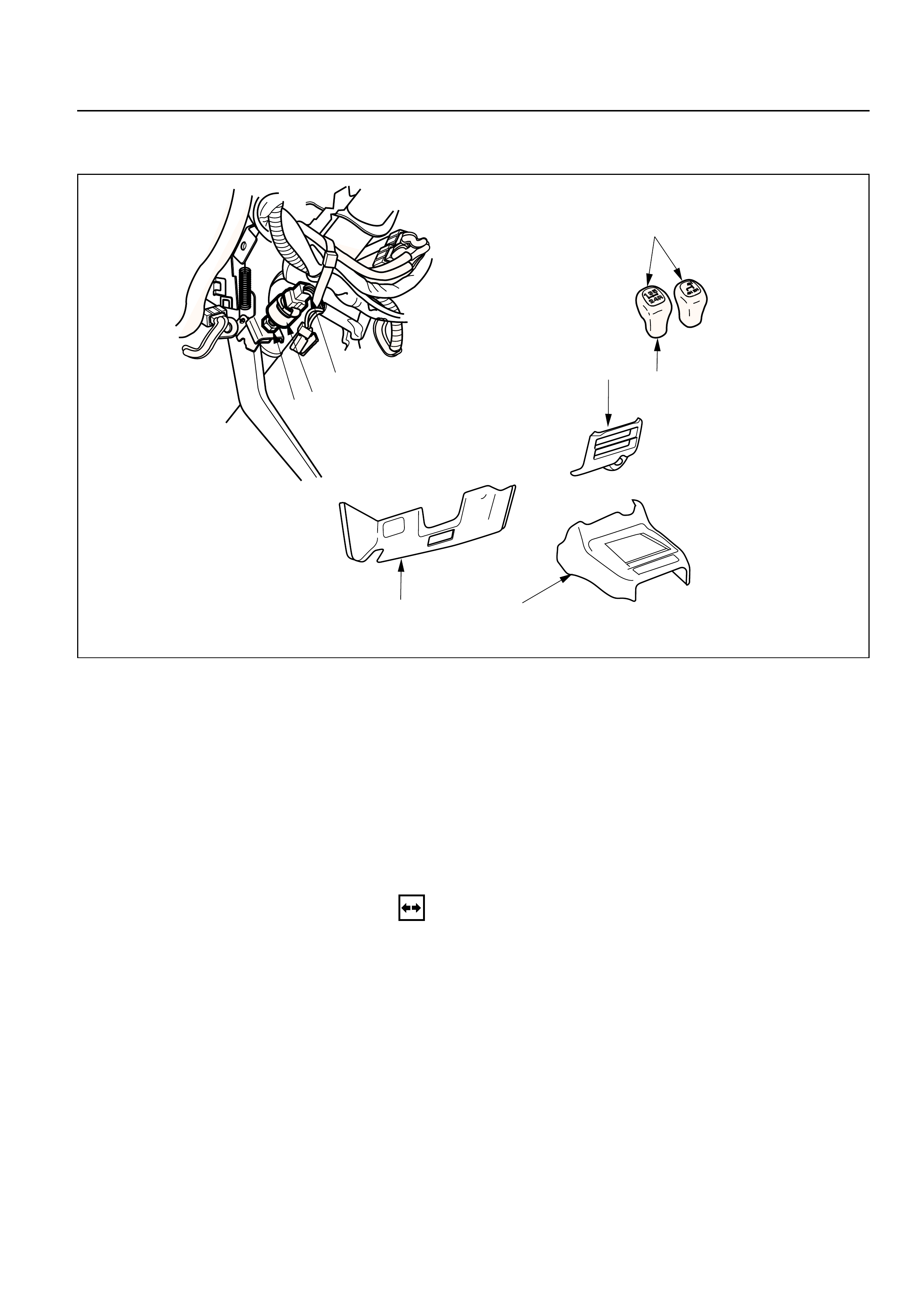
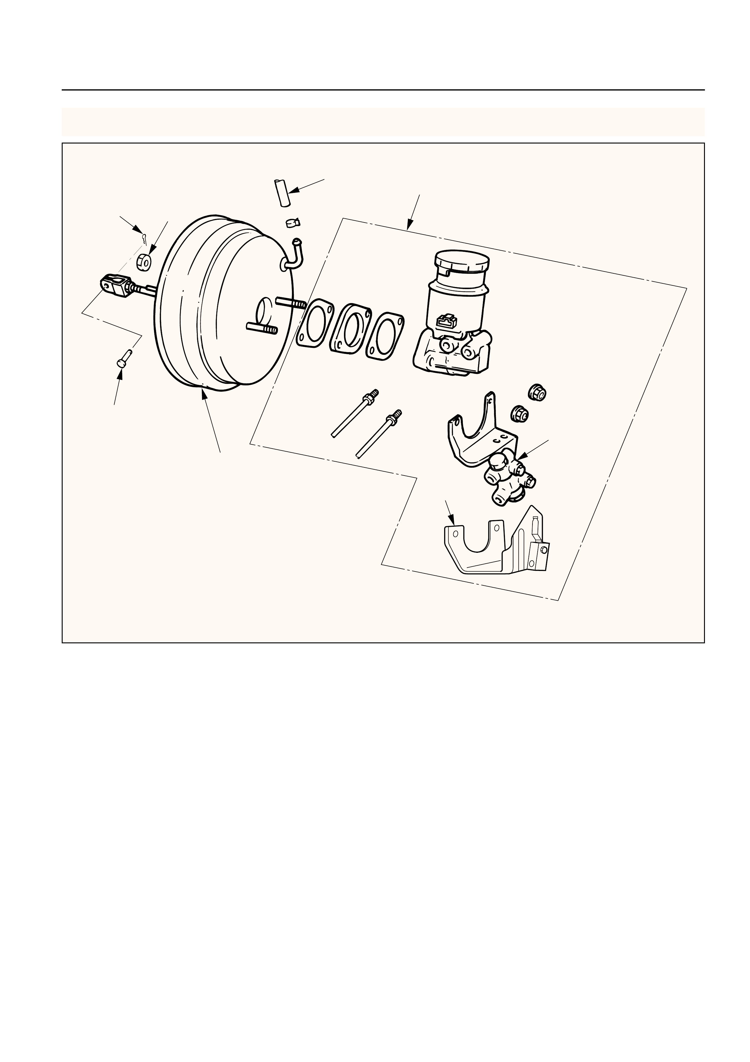
EXTERIOR COMPONENTS
P&B valve
equipped
vehicle
LSPV
equipped
vehicle
1
10
11
2
9
345678
Removal Steps
1. Master cylinder
2. Vacuum booster
3. Yoke clevis
4. Lock nut
5. Retaining clip
6. Valve body guard
7. Silencer
8. Filter
9. 2 gaskets and spacer
10. Retainer
11. Plate and seal assembly
Installation Steps
To install, follow the removal steps in the
reverse order.
This illustration is based on the LHD model.
331RW011
REMOVAL
1.Master Cylinder
•Refer to Master Cylinder Assembly in this Section.
2. Vacuum Booster
•Refer to Vacuum Booster Assembly in this
section.
3. Yoke Clevis
4. Lock Nut
5. Retaining Clip
6. Valve Body Guard
7. Silencer
8. Filter
9. 2 gaskets and Spacer
10. Retainer
•Use a small screwdriver to pry out the retainer.
Gently pull out the plate and seal assembly from
the shell.
11. Plate and Seal Assembly
INSPECTION AND REPAIR
Visual Check:
Make necessary parts replacement if cuts, nicks,
excessive wear, or other abnormal conditions are
found through inspection. Check the following parts.
1) Yoke clevis
2) Valve body guard
3) Silencer
4) Filter
5) Plate and seal assembly
INSTALLATION
11. Plate and Seal Assembly
10. Retainer
9. 2 gaskets and Spacer
8. Filter
7. Silencer
6. Valve Body Guard
5. Retaining Clip
4. Lock Nut
Lock Nut Torque N·m (kg·m / lb·ft)
20 (2.0 / 15)

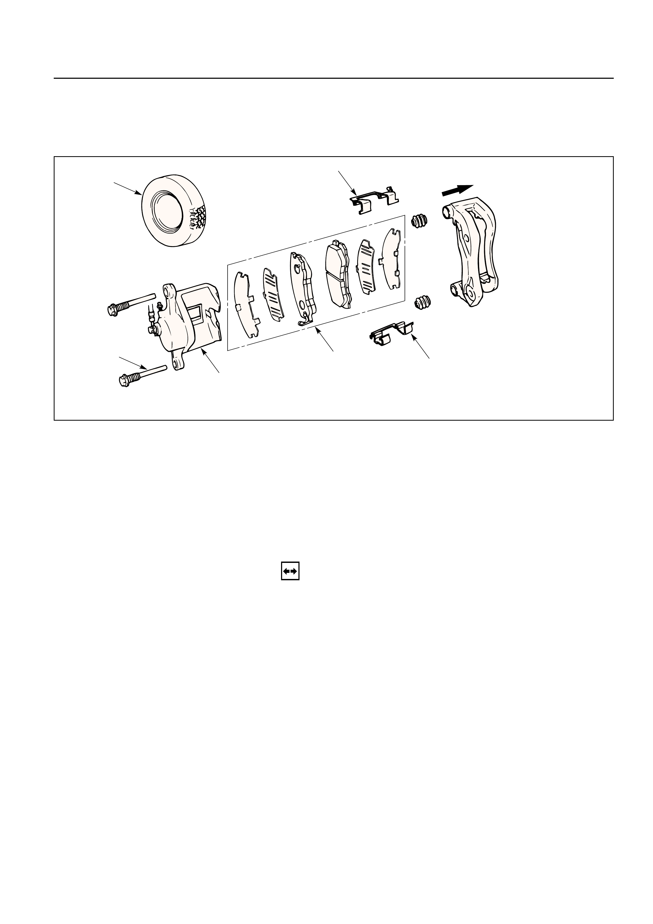
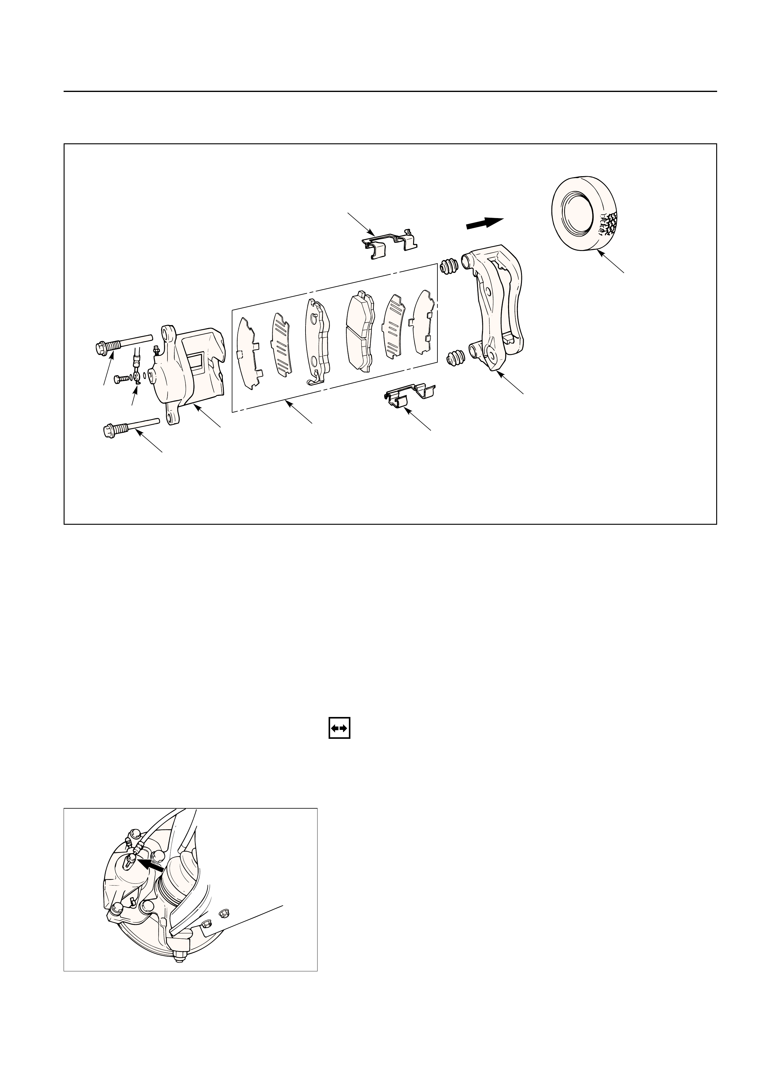
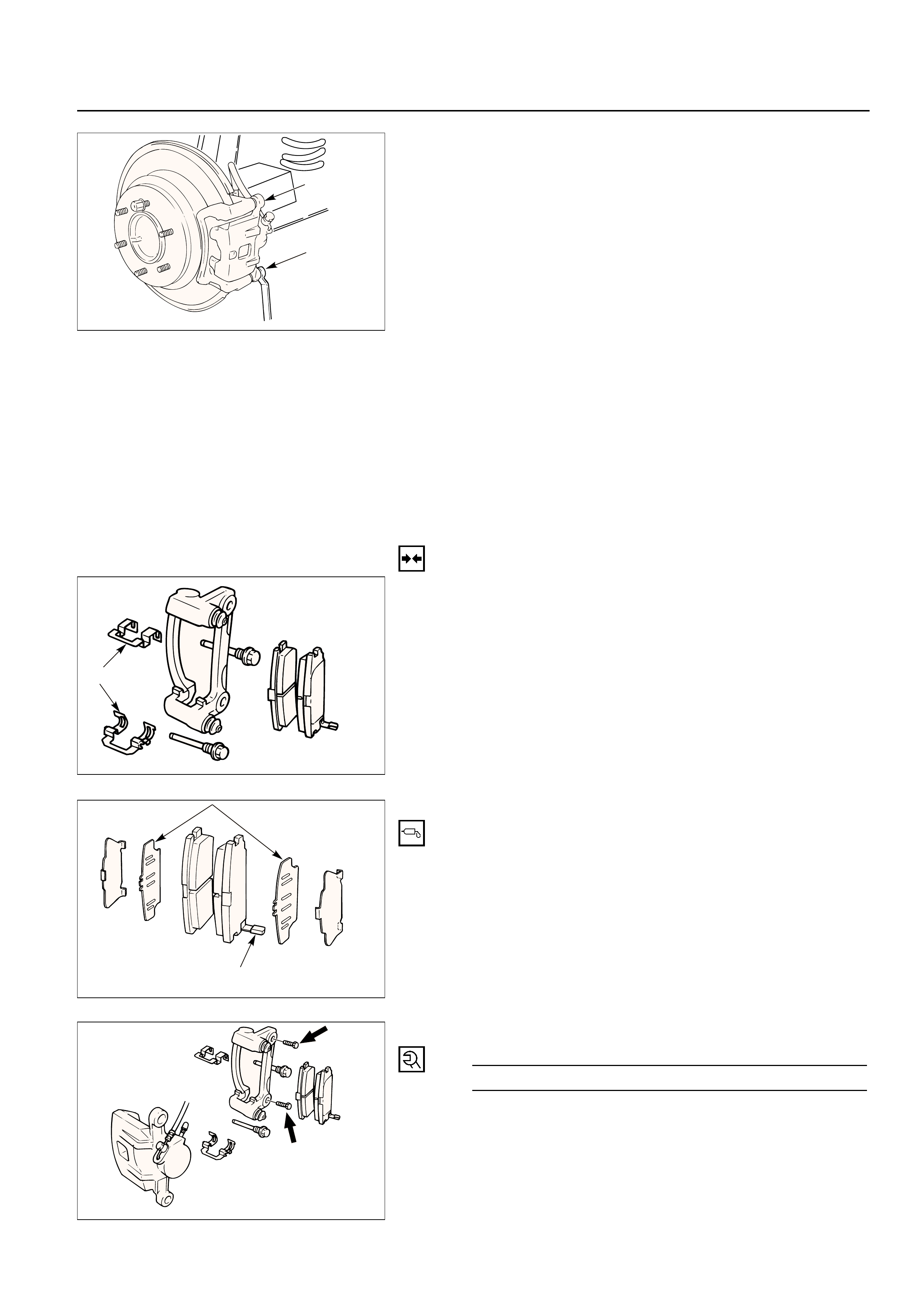
FRONT DISC BRAKE
BRAKE PADS REPLACEMENT
Outer side
1
2
3
45
5
Removal Steps
1.Wheel and tire assembly
2.Lock bolt
3.Caliper assembly
4.Pad assembly with shim
5.Clip
Installation Steps
To install, follow the removal steps in the
reverse order.
REMOVAL
NOTE:
If a squealing noise occurs from the front brake while
driving, check the pad wear indicator plate. If the
indicator plate contacts the rotor, the disc pad
assembly should be replaced.
Preparation:
1)Draw out two-thirds of the brake fluid from the
reservoir.
2)Raise the vehicle and support it with suitable
safety stands.
1.Wheel and Tire Assembly
•Refer to Wheels and Tires in Suspension section.
2. Lock Bolt
3. Caliper Assembly
•Support the caliper assembly so that the brake
hose is not stretched or damaged.
4. Pad Assembly with Shim
5. Clip
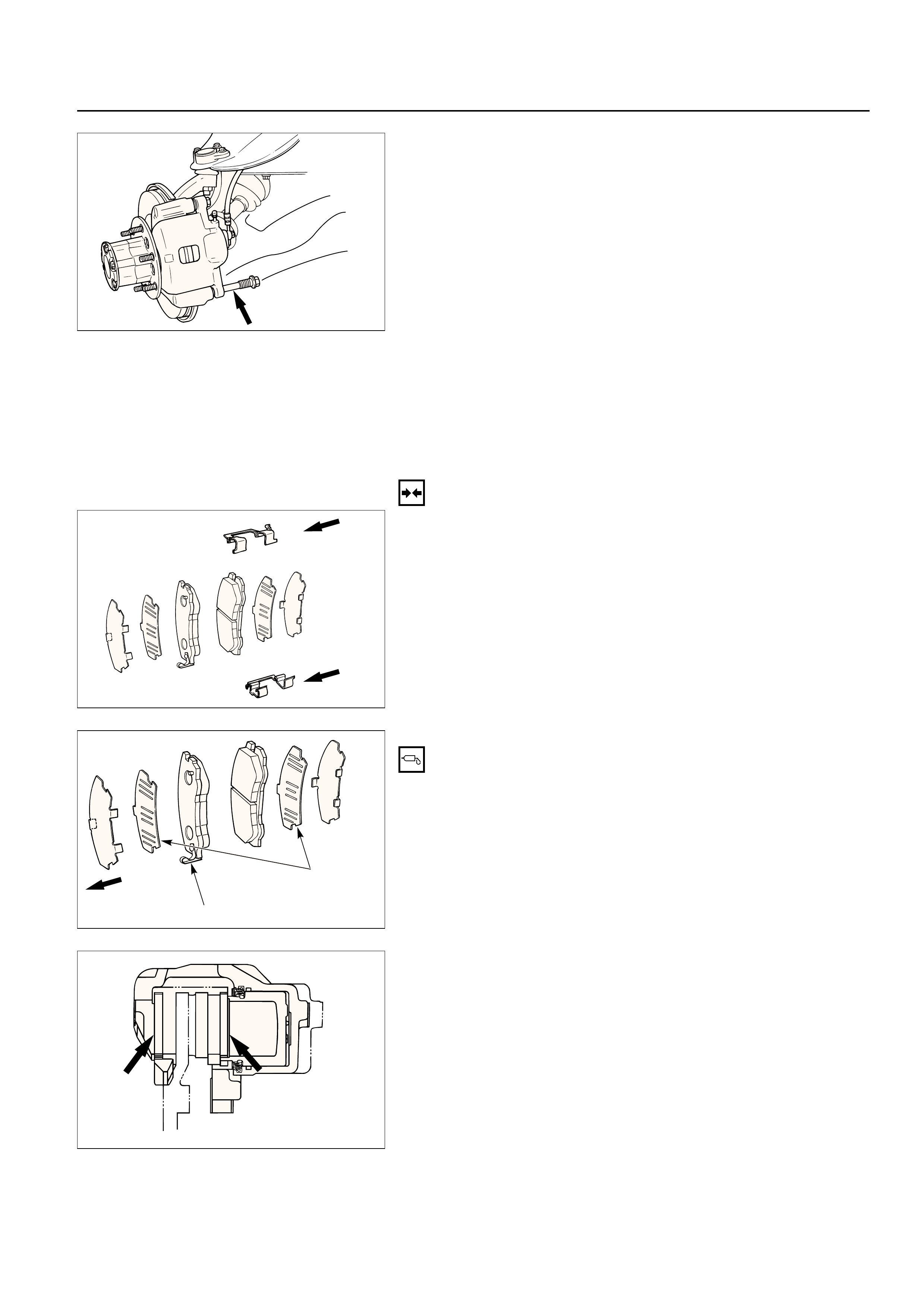
INSTALLATION
5. Clip
4. Pad Assembly with Shim
•Apply special grease (approx 0.2 g) to both
contacting surfaces of inner shims. Wipe off
extruded grease after installing.
Inner side
Inner shim
Wear indicator
Apply
special
grease
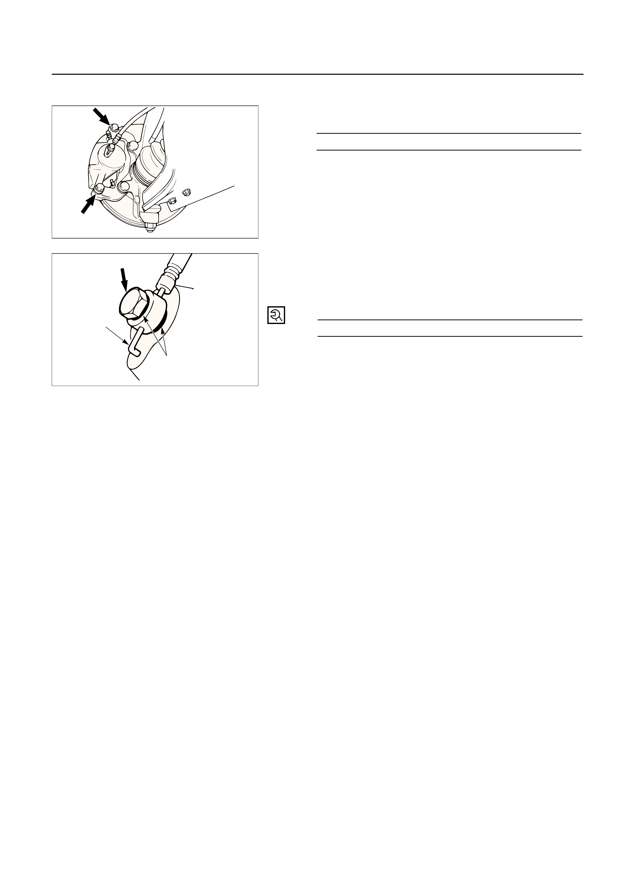
3.Caliper Assembly
1)Use adjustable pliers to bottom the piston into the
caliper bore. Be careful not to damage the piston
dust boot.
2)Do not damage the flexible hose by twisting or
pulling it.
2.Lock Bolt
Lock Bolt TorqueN·m (kg·m / lb·ft)
74 (7.5 / 54)
1.Wheel and Tire Assembly
1)Refer to Wheels and Tires in Suspension section.
2) Pump the brake pedal several times to make sure
that the pedal is firm. Check the brake fluid level
in the reservoir after pumping the brakes.
REMOVAL
Raise the vehicle and support with suitable safety
stands
1.Wheel and Tire Assembly
•Refer to Wheels and Tires in Suspension section.
2. Brake Flexible Hose
1) Remove the bolt and gaskets, then disconnect the
flexible hose from the caliper.
2) After disconnecting the flexible hose, cap or tape
the openings to prevent entry of foreign material.
3) Since the brake fluid flows out from the
connecting coupler, place a drain pan under the
vehicle.
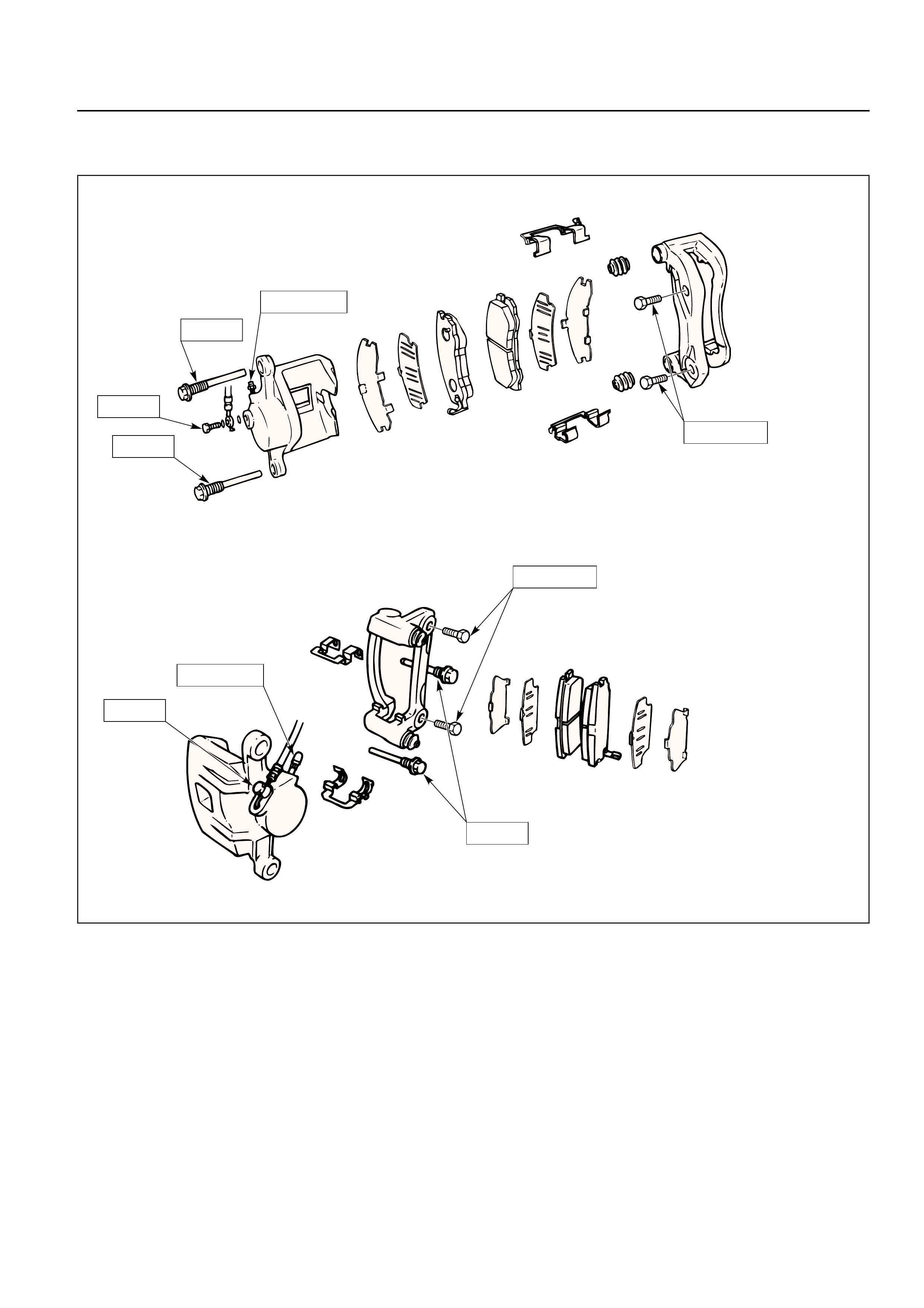
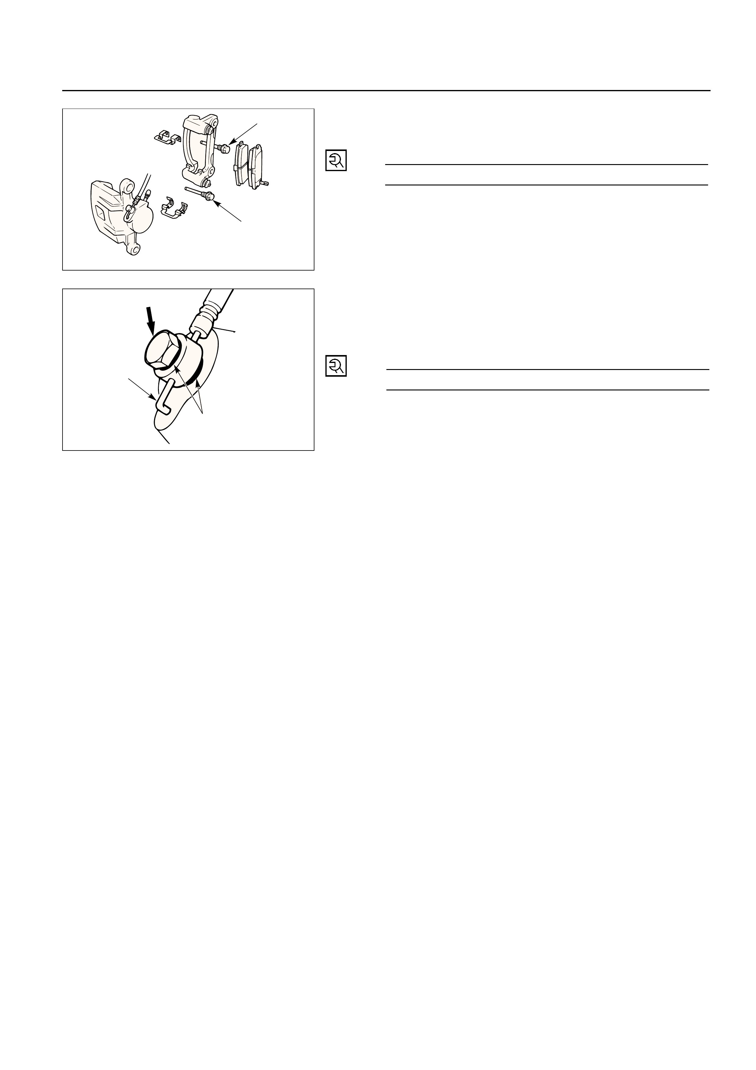
CALIPER REPLACEMENT
Outer side
4
3
2
7
58
8
6
1
Removal Steps
1. Wheel and tire assembly
2. Brake flexible hose
3. Guide bolt
4. Lock bolt
5. Caliper assembly
6. Support bracket with pad assembly
7. Pad assembly with shim
8. Clip
Installation Steps
To install, follow the removal steps in the
reverse order.

3. Guide Bolt
4. Lock Bolt
5. Caliper Assembly
6. Support Bracket with Pad Assembly
•Take care not to damage the flexible brake hose
when removing the support bracket.
7. Pad Assembly with Shim
•Mark the lining locations if they are to be
reinstalled.
8. Clip
INSTALLATION
8. Clip
7. Pad Assembly with Shim
•Apply special greae (approx 0.2 g) to the both
contacting surfaces of inner shims. Wipe off
extruded grease after installing.
6. Support Bracket
Support Bracket Torque N·m (kg·m / lb·ft)
155 (15.8 / 115)
4
3
Inner side
Inner shim
Wear indicator
5.Caliper Assembly
4, 3.Lock Bolt and Guide Bolt
Lock Bolt and Guide Bolt TorqueN·m (kg·m / lb·ft)
74 (7.5 / 54)
2.Brake Flexible Hose
1)Always use new gaskets.
2)Be sure to put the hooked edge of the flexible
hose end into the anti-rotation cavity.
Brake Flexible Hose TorqueN·m (kg·m / lb·ft)
35 (3.5 / 26)
1.Wheel and Tire Assembly
1)Refer to Wheels and Tires in Suspension section.
2)Bleed brakes. Refer to Bleeding Brake Hydraulic
System in this section.
Hooked edge
Gasket
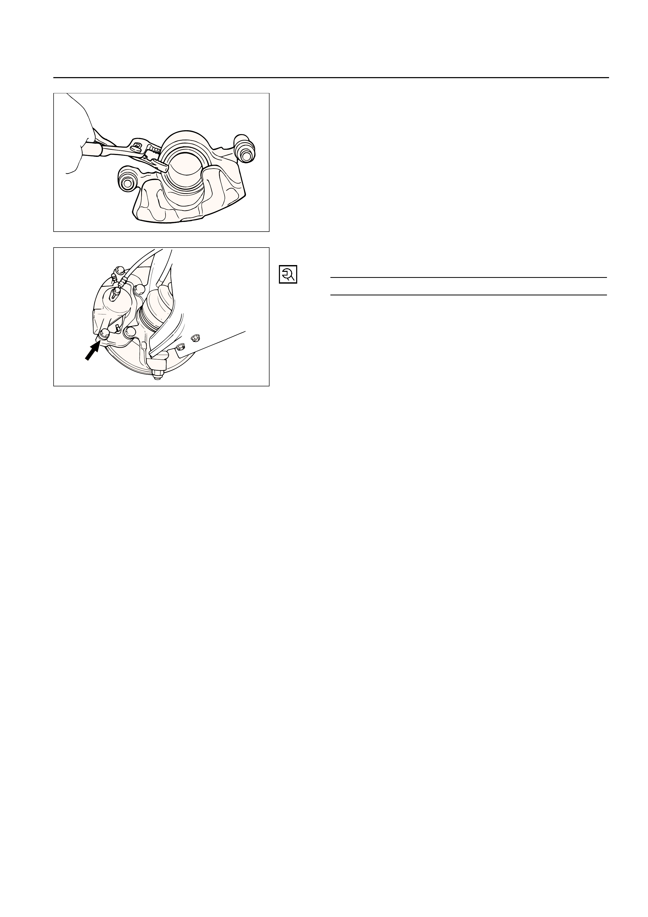
DISASSEMBLY
1. Guide Bolt
2. Lock Bolt
3. Dust Boot; Guide Bolt and Lock Bolt
4. Dust Boot Ring
•Using a small screwdriver, remove the dust boot
ring.
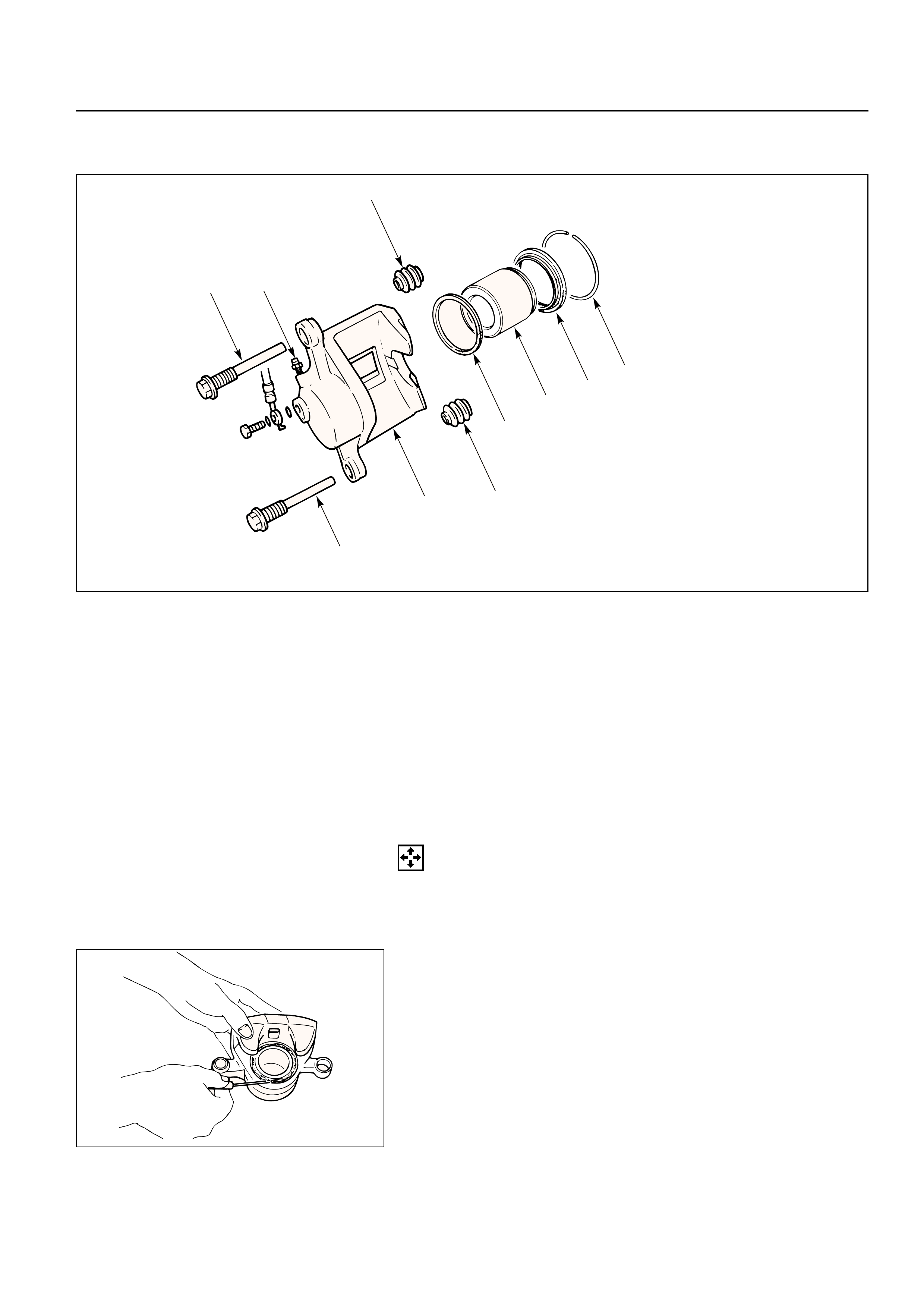
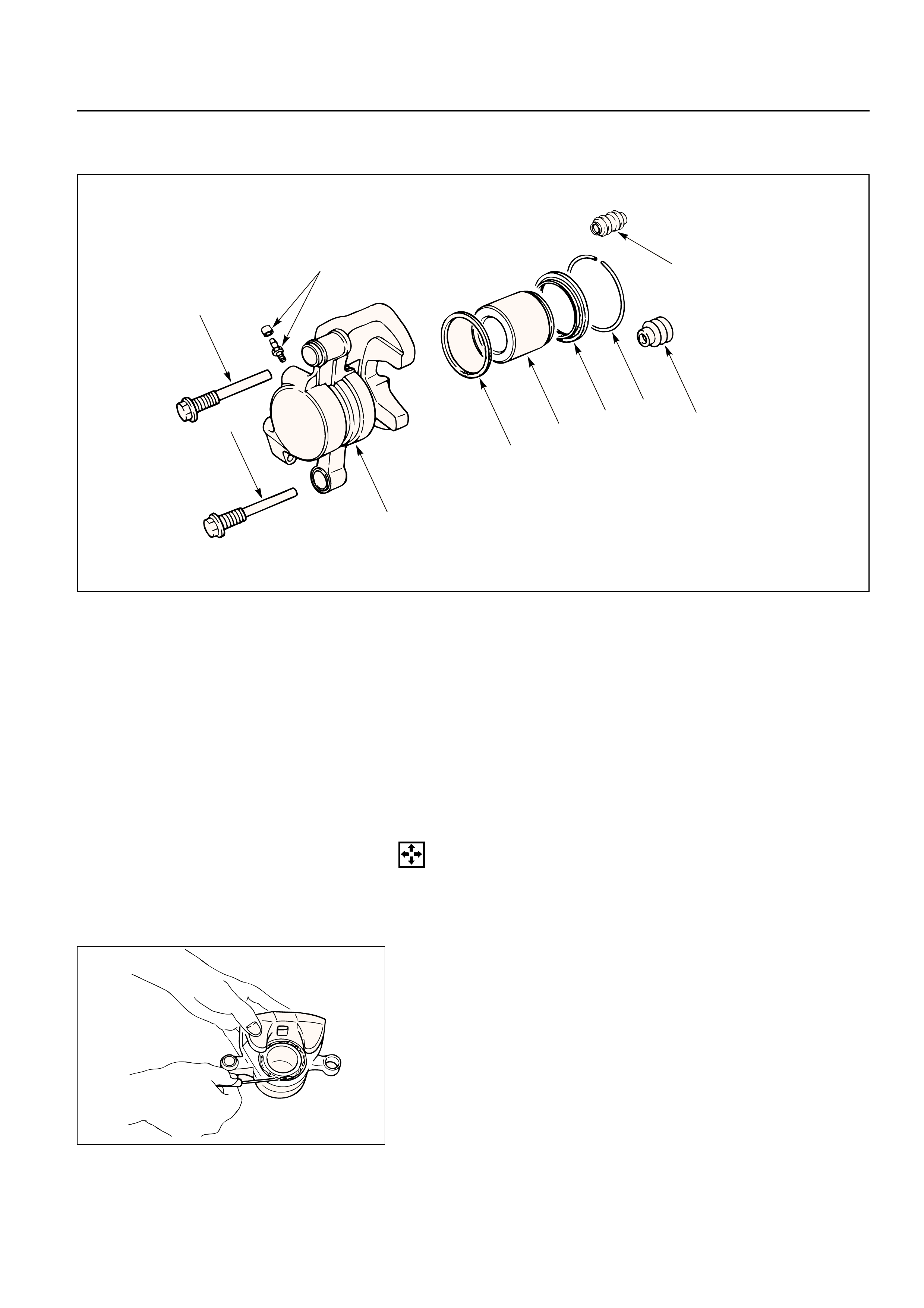
REBUILDING THE CALIPER
4
6
5
7
3
8
3
2
1
9
Disassembly Steps
1. Guide bolt
2. Lock bolt
3. Dust boot; guide bolt and lock bolt
4. Dust boot ring
5. Piston
6. Dust boot; piston
7. Piston seal
8. Bleeder with cap
9. Caliper body
Reassembly Steps
9. Caliper body
8. Bleeder with cap
7. Piston seal
5. Piston
6. Dust boot; piston
4. Dust boot ring
3. Dust boot; guide bolt and lock bolt
2. Lock bolt
1. Guide bolt
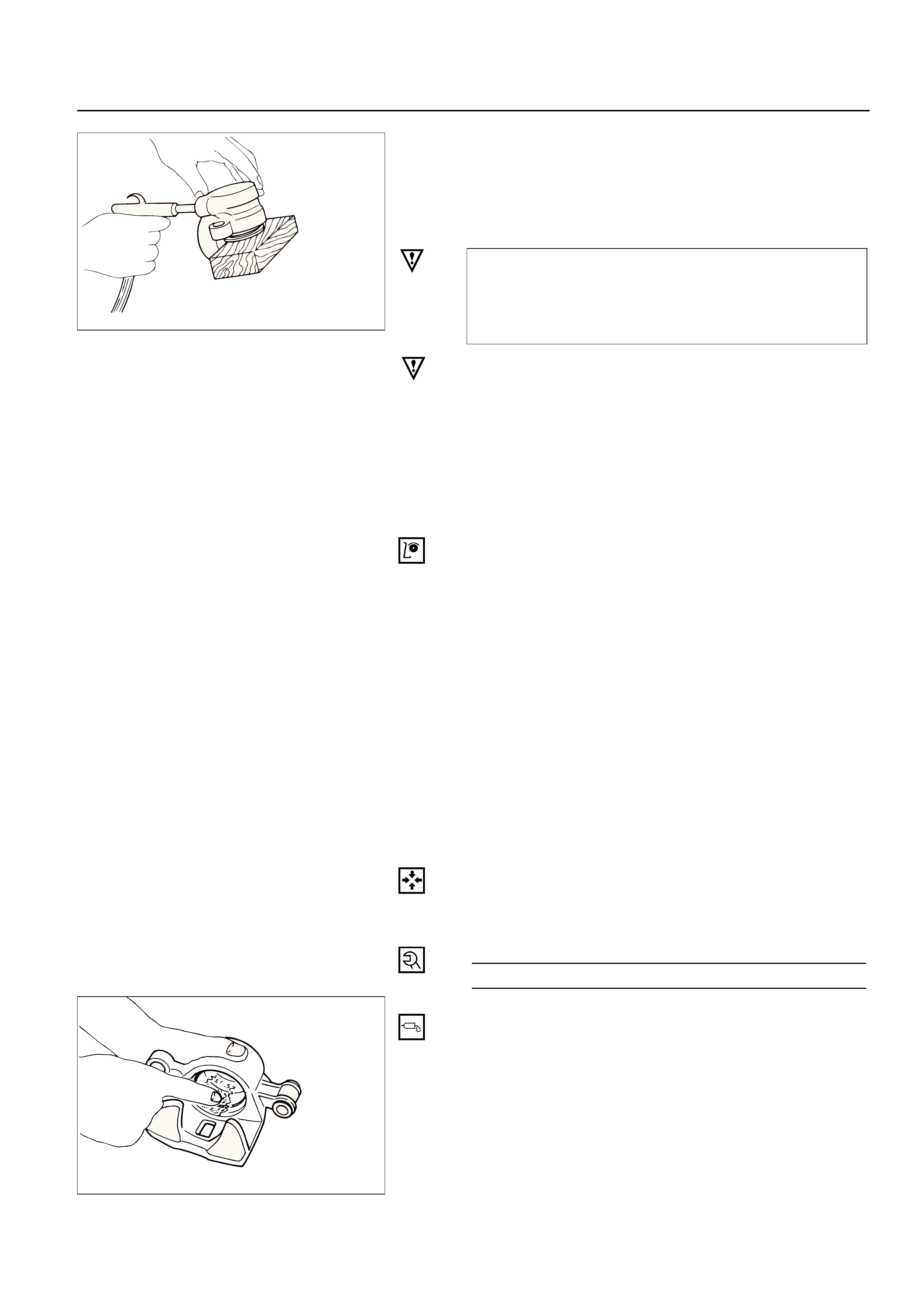
5.Piston
•Insert a block of wood into the caliper and force
out the piston by blowing compressed air into the
caliper at the flexible hose attachment. This
procedure must be done prior to removal of dust
boot.
WARNING:
DO NOT PLACE YOUR FINGERS IN FRONT OF THE
PISTON IN AN ATTEMPT TO CATCH OR PROTECT IT
WHEN APPLYING COMPRESSED AIR. THIS COULD
RESULT IN PERSONAL INJURY.
CAUTION:
Use just enough air to ease the piston out of the
bore. If the piston is blown out, it may be damaged.
6. Dust Boot; Piston
7. Piston Seal
8. Bleeder with Cap
9. Caliper Body
REASSEMBLY
9. Caliper Body
8. Bleeder with Cap
Bleeder Torque N·m (kg·cm / lb·in)
8 (80 / 69)
7. Piston Seal
•Apply special rubber grease to the piston seal and
cylinder wall, then insert the piston seal into the
cylinder. The special rubber grease is included in
the repair kit.
INSPECTION AND REPAIR
Make necessary parts replacement, if wear, damage,
corrosion or any other abnormal conditions are found
through inspection.
Check the following parts;
•Rotor
•Cylinder body
•Cylinder bore
•Piston
•Guide bolt, Lock bolt
•Support bracket
NOTE:
The piston seal, boot ring and dust boot are to be
replaced each time the caliper is overhauled.
Discard these used rubber parts and replace with
new ones.
5. Piston
6. Dust Boot; Piston
•When inserting the piston into the cylinder, use
finger pressure only. Do not use a mallet or other
impact tools, since damage to the cylinder wall or
piston seal can result.
4. Dust Boot Ring
•Apply special grease (Approx. 1 g) to the piston
and attach the dust boot to the piston and caliper.
Insert the dust boot ring into the dust boot.
3. Dust Boot; Guide Bolt and Lock Bolt
2, 1. Lock Bolt and Guide Bolt
Lock and Guide Bolt Torque N·m (kg·m / lb·ft)
74 (7.5 / 54)
•Install the dust boot on the support bracket after
applying special grease (Approx. 1 g) onto the
dust boot inner surface. Also apply special grease
onto the lock bolt and guide bolt setting hole of
the support bracket.
REAR DISC BRAKE
BRAKE PADS REPLACEMENT
1
5
5
3
2
4
Removal Steps
1.Wheel and tire assembly
2.Lock bolt
3.Caliper assembly
4.Pad assembly with shim
5.Clip
Installation Steps
To install, follow the removal steps in the
reverse order.
REMOVAL
NOTE:
If a squealing noise occurs from the rear brake while
driving, check the pad wear indicator plate. If the
indicator plate contacts the rotor, the disc pad
assembly should be replaced.
1)Draw out two-thirds of the brake fluid from the
reservoir.
2)Raise the vehicle and support it with suitable
safety stands.
1.Wheel and Tire Assembly
•Refer to Wheels and Tires in Suspension section.
2. Lock Bolt
3. Caliper Assembly
•Support the caliper assembly so that the brake
hose is not stretched or damaged.
4. Pad Assembly with Shim
5. Clip
INSTALLATION
5. Clip
Clip
4. Pad Assembly with Shim
•Apply special grease (approx. 0.2 g) to both
contacting surfaces of inner shims. Wipe off
extruded grease after installing.
Inner shim
Wear indicator
Apply
special
grease
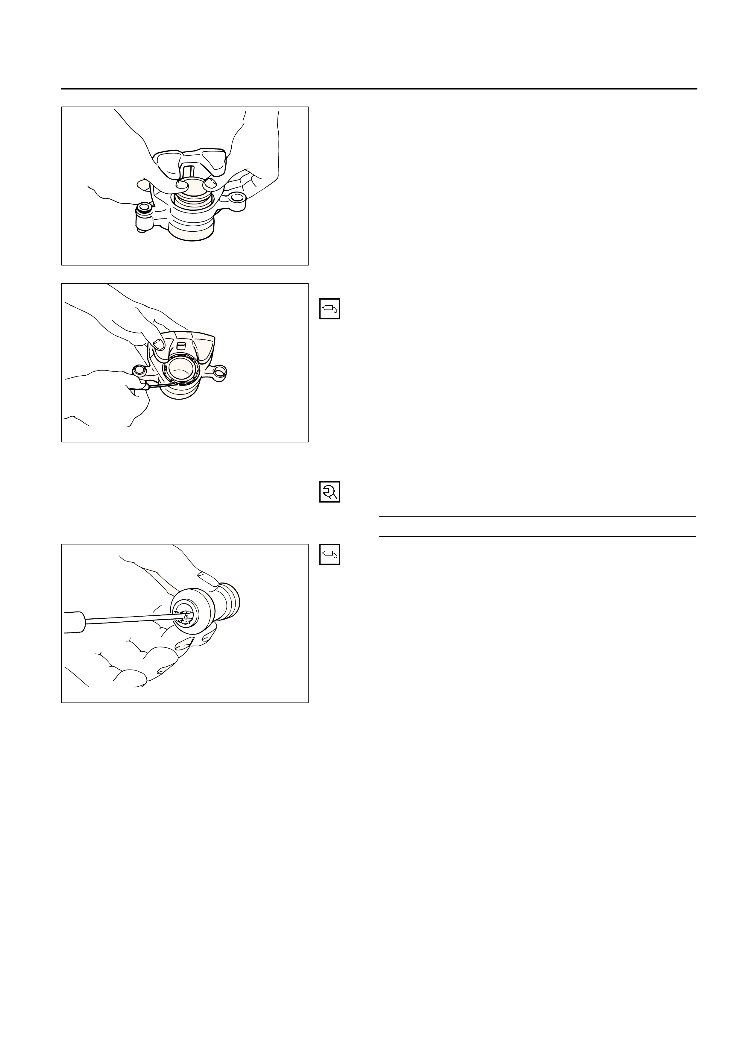
3. Caliper Assembly
1) Use adjustable pliers to bottom the piston into the
caliper bore. Be careful not to damage the piston
dust boot.
2) Do not damage the flexible hose by twisting or
pulling it.

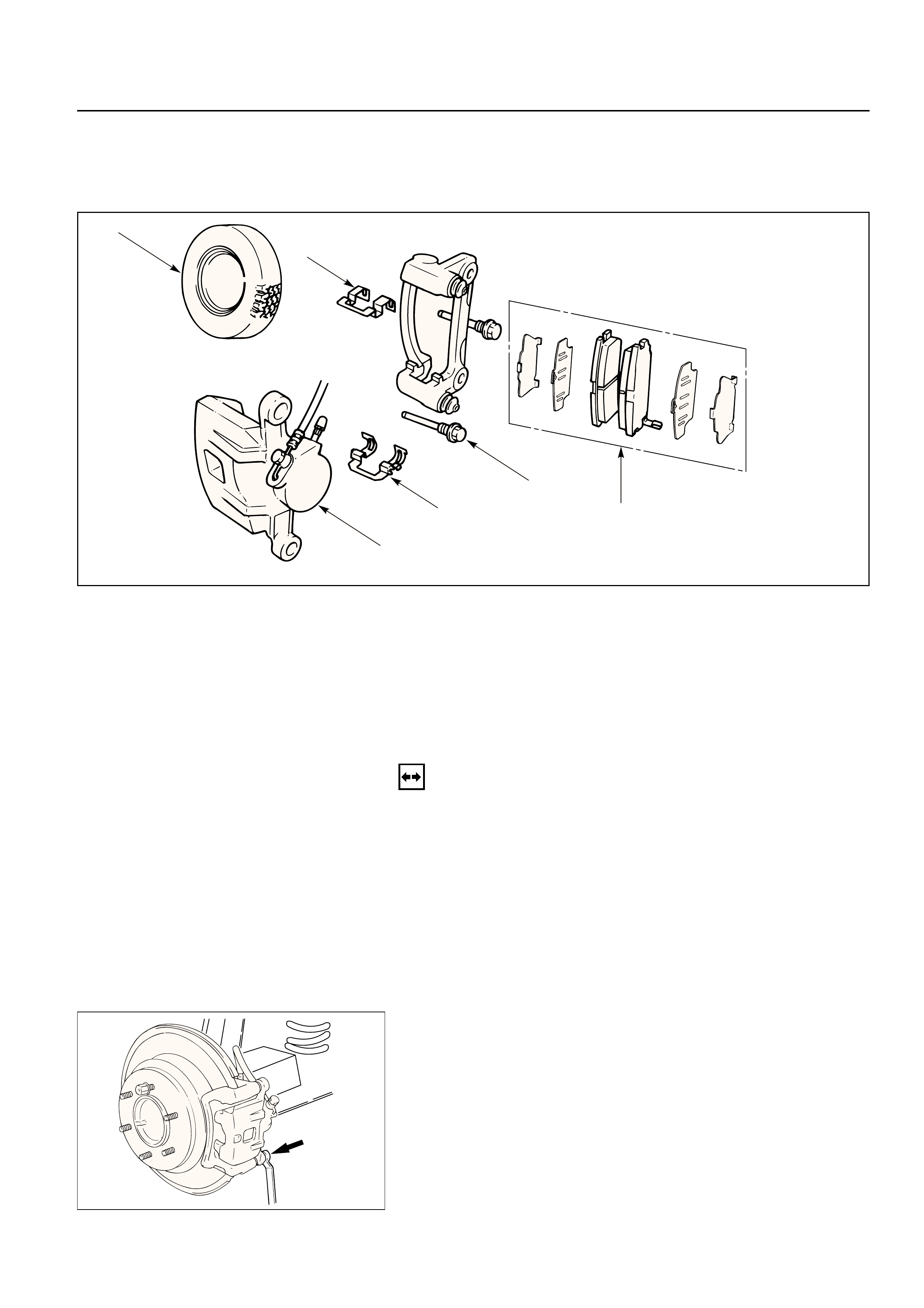
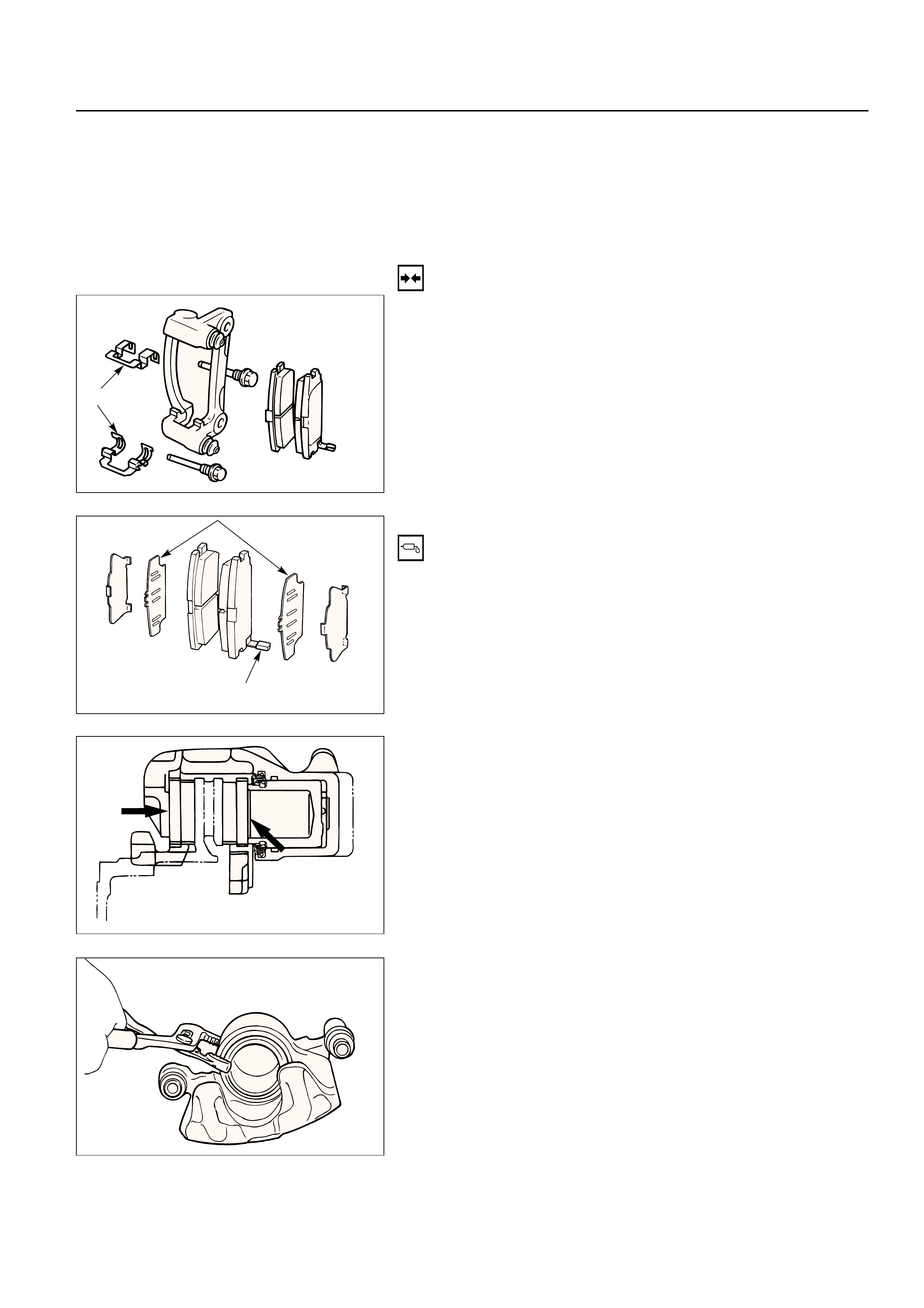
CALIPER REPLACEMENT
7
1
4
6
8
8
5
2
3
Removal Steps
1.Wheel and tire assembly
2.Brake flexible hose
3.Lock bolt
4.Guide bolt
5.Caliper assembly
6.Support bracket
7.Pad assembly with shim
8.Clip
Installation Steps
To install, follow the removal steps in the
reverse order.
REMOVAL
•Raise the vehicle and support with suitable safety
stands.
1.Wheel and Tire Assembly
•Refer to Wheels and Tires in Suspension section.
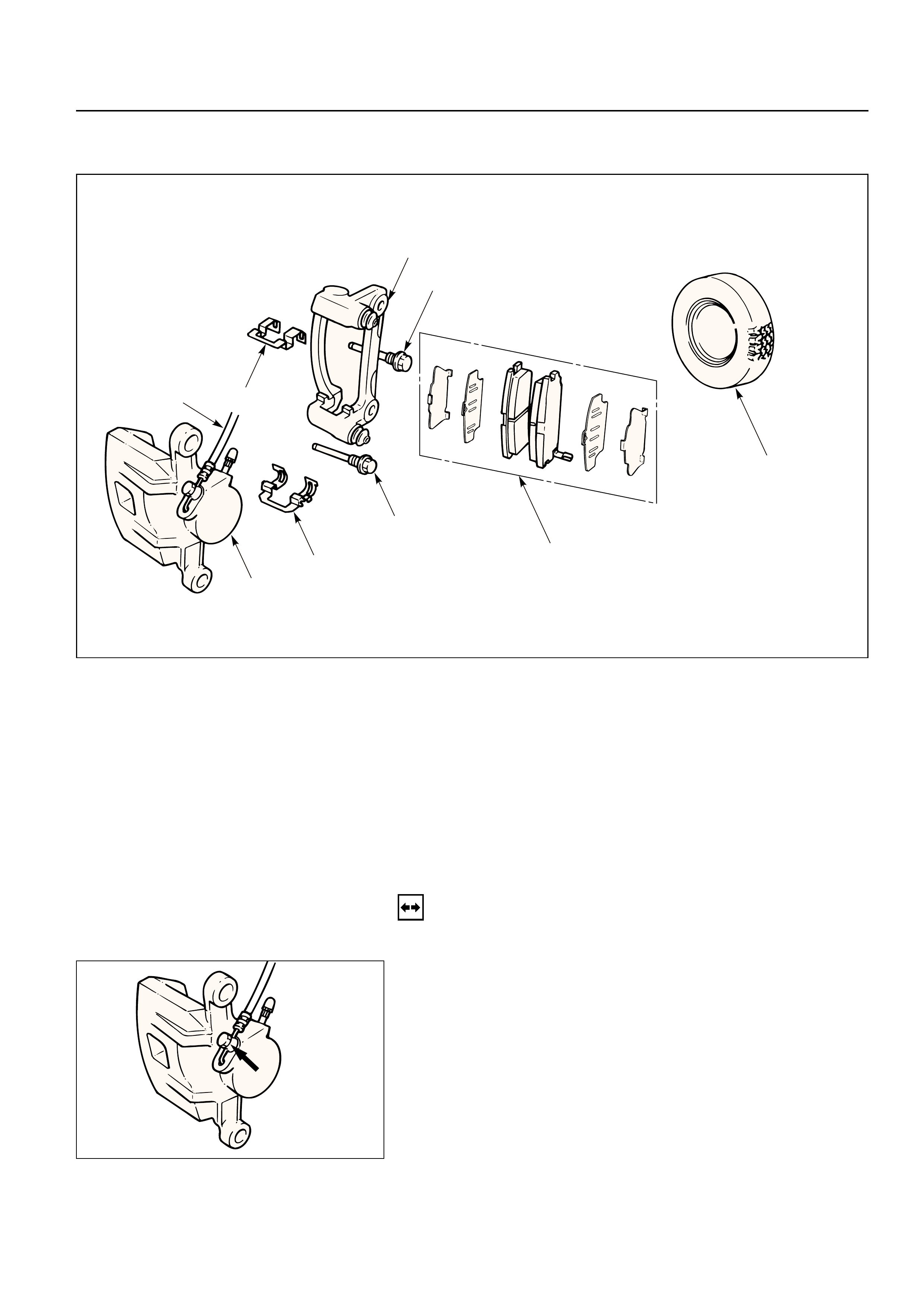
2. Brake Flexible Hose
1) Remove the bolt and gaskets, then disconnect the
flexible hose from the caliper.
2) After disconnecting the flexible hose, cap or tape
the openings to prevent entry of foreign material.
3) Since the brake fluid flows out from the
connecting coupler, place a drain pan under the
vehicle.
3. Lock Bolt
4. Guide Bolt
4
3
5. Caliper Assembly
6 Support Bracket
•Take care not to damage the flexible brake hose
when removing the support bracket.
7. Pad Assembly with Shim
•Mark the lining locations if they are to be
reinstalled.
8. Clip
INSTALLATION
8. Clip
Clip
7. Pad Assembly with Shim
•Apply special grease (approx. 0.2 g) to both
contacting surfaces of inner shims. Wipe off
extruded grease after installing.
Inner shim
Wear indicator
6. Support Bracket
Support Bracket Torque N·m (kg·m / lb·ft)
104 (10.6 / 77)
5. Caliper Assembly
4.Guide Bolt
3.Lock Bolt
Lock Bolt TorqueN·m (kg·m / lb·ft)
44 (4.5 / 32)
3
4
2.Brake Flexible Hose
1)Always use new gaskets.
2)Be sure to put the hooked edge of the flexible
hose end into the anti-rotation cavity.
Brake Flexible Hose TorqueN·m (kg·m / lb·ft)
35 (3.5 / 26)
Hooked edge
Gasket
1.Wheel and Tire Assembly
1)Refer to Wheels and Tires in Suspension section.
2) Bleed brakes.
REBUILDING THE CALIPER
3
4
6
5
7
9
1
2
3
8
Disassembly Steps
1. Guide bolt
2. Lock bolt
3. Dust boot
4. Dust boot ring
5. Piston
6. Dust boot; piston
7. Piston seal
8. Bleeder with cap
9. Caliper body
Reassembly Steps
9. Caliper body
8. Bleeder with cap
7. Piston seal
5. Piston
6. Dust boot; pisotn
4. Dust boot ring
3. Dust boot
2. Lock bolt
1. Guide bolt
DISASSEMBLY
1. Guide Bolt
2. Lock Bolt
3. Dust Boot
4. Dust Boot Ring
•Using a small screwdriver, remove the dust boot
ring.

5.Piston
•Insert a block of wood into the caliper and force
out the piston by blowing compressed air into the
caliper at the flexible hose attachment. This
procedure must be done prior to removal of dust
boot.
WARNING:
DO NOT PLACE YOUR FINGERS IN FRONT OF THE
PISTON IN AN ATTEMPT TO CATCH OR PROTECT IT
WHEN APPLYING COMPRESSED AIR. THIS COULD
RESULT IN PERSONAL INJURY.
CAUTION:
Use just enough air to ease the piston out of the
bore. If the piston is blown out, it may be damaged.
6. Dust Boot; Piston
7. Piston Seal
8. Bleeder with Cap
9. Caliper Body
REASSEMBLY
9. Caliper Body
8. Bleeder with Cap
Bleeder Torque N·m (kg·cm / lb·in)
8 (80 / 69)
7. Piston Seal
•Apply special rubber grease to the piston seal and
cylinder wall, then insert the piston seal into the
cylinder. The special rubber grease is included in
the repair kit.
INSPECTION AND REPAIR
Make necessary parts replacement, if wear, damage,
corrosion or any other abnormal conditions are found
through inspection.
Check the following parts;
•Rotor
•Cylinder body
•Cylinder bore
•Piston
•Slide pin
•Support bracket
NOTE:
The piston dust seal and dust boot are to be replaced
each time the caliper is overhauled.
Discard these used rubber parts and replace with
new ones.
5. Piston

6. Dust Boot; Piston
•When inserting the piston into the cylinder, use
finger pressure only. Do not use a mallet or other
impact tools, since damage to the cylinder wall or
piston seal can result.
4. Dust Boot Ring
•Apply special grease (Approx. 1 g) to the piston
and attach the dust boot to the piston and caliper.
Insert the dust boot ring into the dust boot.
3. Dust Boot
•Install the dust boot on the support bracket after
applying special grease (Approx 1 g) onto the
dust boot inner surface. Also apply special grease
onto the lock bolt and guide bolt setting hole of
the support bracket.
2. Lock Bolt
1. Guide Bolt
Guide Bolt Torque N·m (kg·m / lb·ft)
44 (4.5 / 32)
UNIT REPAIR
MASTER CYLINDER
The master cylinder is not repairable and must be
replaced as complete assembly if found defective.
INSPECTION
Excessive brake pedal travel, malfunction or dragging
brake suggests that the master cylinder is defective.
In such cases perform the following visual check.
Visual check
Make parts replacement as required if wear,
distortion, nicks, cuts, corrosion, or other abnormal
conditions are found through the following parts
inspection;
•Master cylinder body
•Fluid reservoir
•O-ring
Primary piston
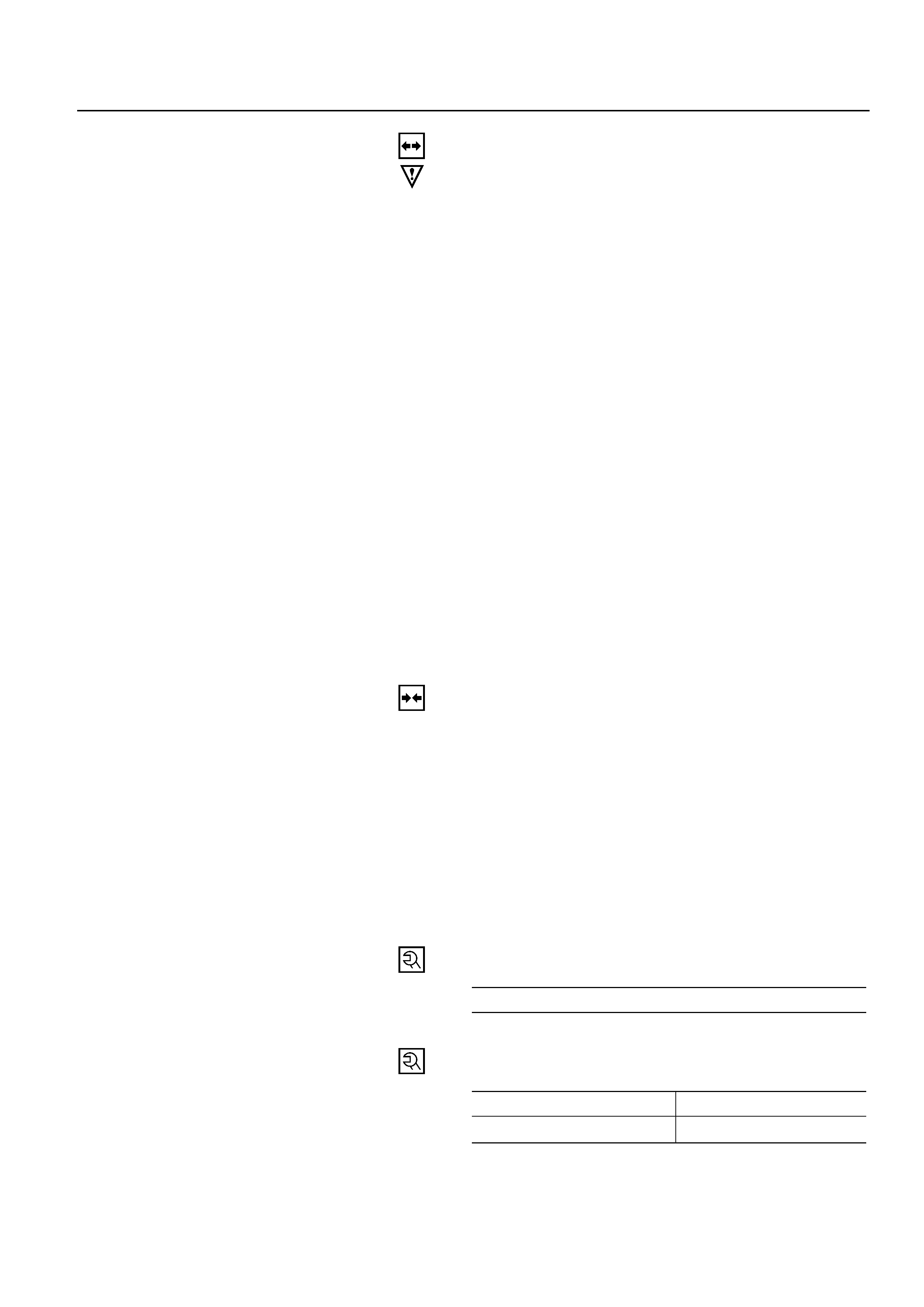
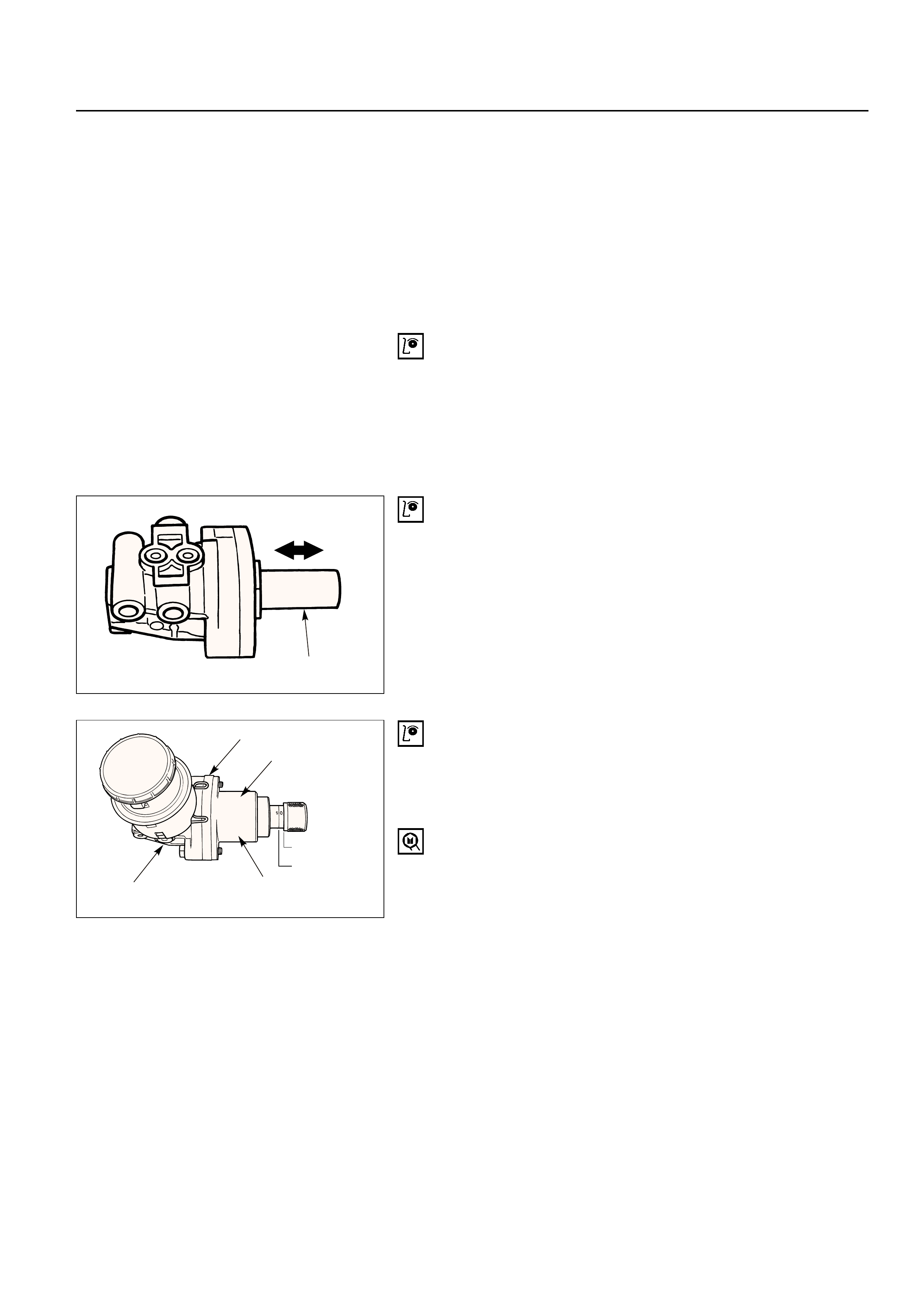
FUNCTIONAL INSPECTION OF MASTER
CYLINDER PISTON
Push the primary piston with your fingers to check
that it travels smoothly. If the motion is questionable,
replace the master cylinder as a complete assembly.
FUNCTIONAL INSPECTION OF MASTER
CYLINDER
Inspect the master cylinder for function as follows. If
any abnormal function is found, replace with a new
one.
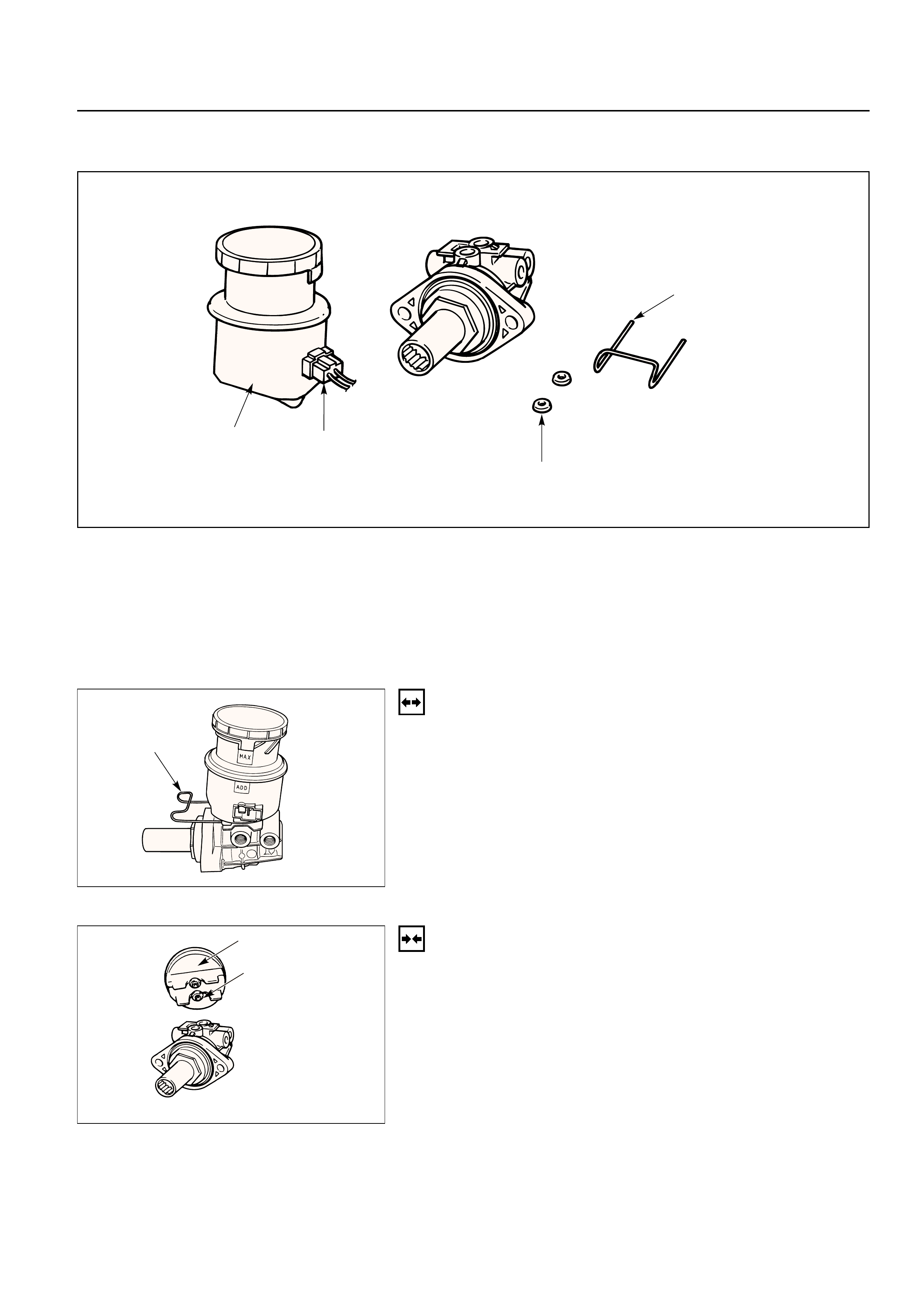
Primary piston holder: 5-8840-2306-0 (J-39242)
(including master cylinder attachment and master
cylinder plug)
•Install the primary piston holder onto the master
cylinder with the spacer (2 bolts) with its adjusting
bolt screwed in up to the “0” line.
Master cylinder
Spacer
5-8840-2306-0
Primary piston holder
"0" line
"5" line
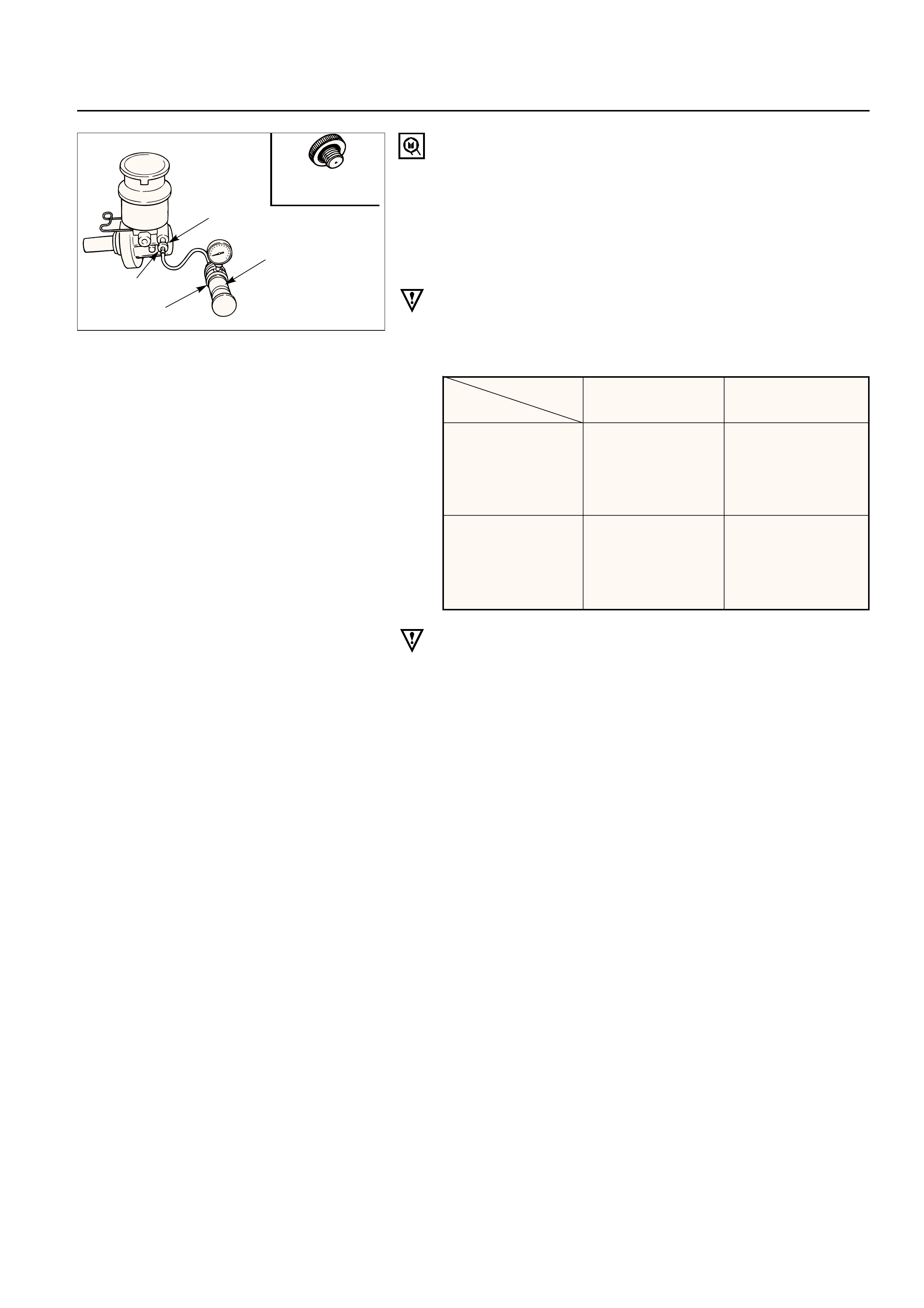
Radiator cap tester: 5-8840-0277-0 (J-24460-01)
•Connect master cylinder attachment with the end
of radiator cap tester, and apply air pressure with
the cap tester. Make sure there is no rise in
pressure and that with the adjusting bolt further
screwed in 5 mm (align the adjusting bolt to the
“5” line). There should be a pressure increase of
49 kpa (0.5 kg/cm2/7.1 psi) or more.
NOTE:
When checking the front (or primary) side, be sure to
mount master cylinder plug in the rear (or secondary)
port.
NOTE:
1)Do not use an air compressor, as the air from
compressor is mixed with compressor oil.
2)When installing the master cylinder onto the
vacuum booster, always adjust vacuum booster
push rod. (Refer to Vacuum Booster Assembly in
this section.)
3) After the master cylinder is installed onto the
vehicle, check for leakage, pedal travel and pedal
free play.
Master cylinder
plug
Master cylinder attachment
5-8840-0277-0
Radiator cap tester
5-8840-2306-0
“0” line “5” line
Apply air No pressure Pressure
pressure to rise. increase of
the front and
49 kpa (0.5 kg/cm2/
rear ports 7.1 psi) more
Remarks Check port into Checks air
the atmospheric tightness of the
pressure pressure
chamber chamber

VACUUM BOOSTER
•The vacuum booster cannot be disassembled for
repair. Replace a defective vacuum booster with a
new one.