
SECTION 5D PARKING BRAKES
Service Precaution
Main Data and Specifications
Service Standard
Servicing
Fixing Torque
General Description
On-Vehicle Service
Parking Brake Lever Replacement
Parking Brake Cable
SERVICE PRECAUTION
WARNING:
IF SO EQUIPPED WITH A SUPPLEMENTAL RESTRAINT SYSTEM (SRS), REFER TO THE SRS COMPONENT
AND WIRING LOCATION VIEW IN ORDER TO DETERMINE WHETHER YOU ARE PERFORMING SERVICE ON
OR NEAR THE SRS COMPONENTS OR THE SRS WIRING. WHEN YOU ARE PERFORMING SERVICE ON OR
NEAR THE SRS COMPONENTS OR THE SRS WIRING, REFER TO THE SRS SERVICE INFORMATION.
FAILURE TO FOLLOW WARNINGS COULD RESULT IN POSSIBLE AIR BAG DEPLOYMENT, PERSONAL
INJURY, OR OTHERWISE UNNEEDED SRS SYSTEM REPAIRS.
CAUTION:
Always use the correct fastener in the proper location. When you replace a fastener, use ONLY the exact
part number for that application. ISUZU will call out those fasteners that require a replacement after
removal. ISUZU will also call out the fasteners that require thread lockers or thread sealant. UNLESS
OTHERWISE SPECIFIED, do not use supplemental coatings (Paints, greases, or other corrosion inhibitors)
on threaded fasteners or fastener joint interfaces. Generally, such coatings adversely affect the fastener
torque and the joint clamping force, and may damage the fastener. When you install fasteners, use the
correct tightening sequence and specification. Following these instructions can help you avoid damage to
parts and systems.

MAIN DATA AND SPECIFICATIONS
REAR PARKING BRAKE
Type Duo-servo
Lining Dimensions cm2(in2) 121.2 (18.79)
Adjusting Method Manual Adjusting
Rear Drum (in Disc)
Inside Diameter mm (in) 210 (8.27)
Parking Brake Lever Stroke 6 to 7 notches
When pulled with a force of 30 kg (66 lb)
SERVICE STANDARD
REAR PARKING BRAKE
Rear Drum (in Disc) Minimum Wear
Inside Diameter mm (in) 211.4 (8.32)
Parking Brake Lining Thickness
Minimum Limit mm (in) 1.0 (0.039)
Parking Brake Lever Stroke 6 to 7 notches
When pulled with a force of 30 kg (66 lb)
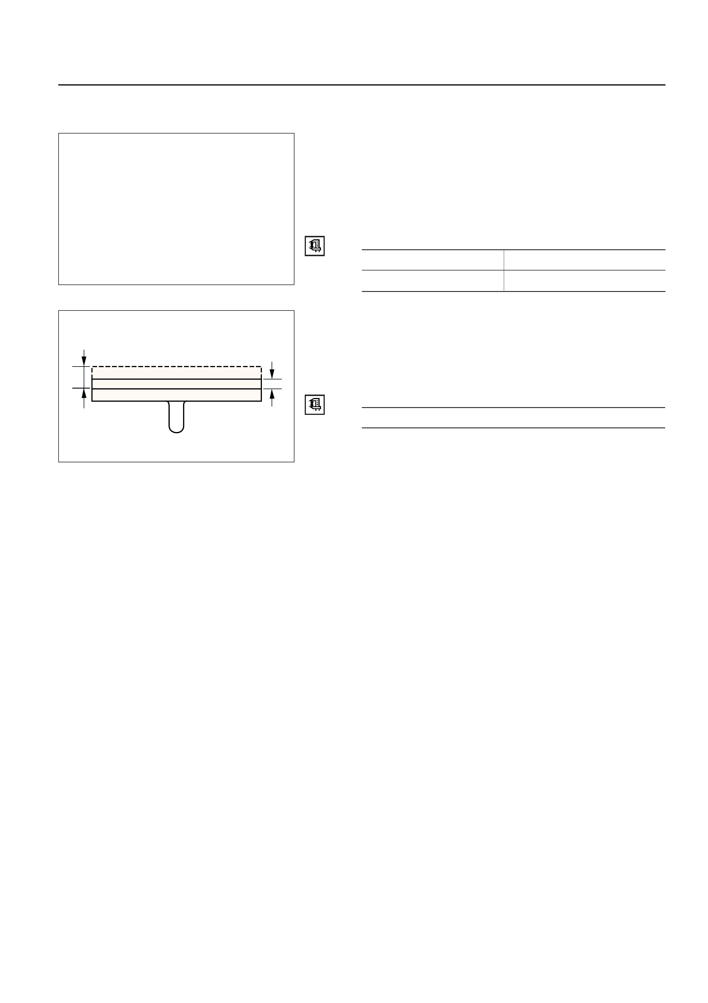
REAR DRUM (IN DISC) INSIDE
DIAMETER CHECK
Check the rear drum inside diameter by measuring at
more than two portions as shown in the figure.
If the inside diameter is greater than the limit, replace
the rear rotor.
Rear Drum Inside Diameter mm (in)
Standard Limit
210.0 (8.27) 211.4 (8.32)
PARKING BRAKE LINING INSPECTION
Check the shoe assemblies for wear by removing the
brake drum rotor.
Replace the shoe assemblies, if the lining thickness is
less than 1.0 mm (0.039 in).
Minimum Limit mm (in)
1.0 (0.039)
PARKING BRAKE ADJUSTMENT
1. Adjustment of Parking Brake Assembly
•Prior to lever stroke adjustment, adjust the rear
brake shoe/rotor (drum) gap. Perform this
procedure by loosening the adjust nut of the
equalizer.
a) Remove the adjusting hole plug (rubber) and
turn the shoe adjusting screw downward with
a small screwdriver so that shoes will expand
until they get into close touch with the rotor.
(Turn down the adjusting screw notch by
notch until the rotor does not turn.)
b) Turn the adjusting screw in the opposite
direction (upward) until the rotor can be turned
lightly. Standard number of notches to turn
upward: 7 or 8.
Turn the rotor and make sure that there is no
brake dragging.
Tt
SERVICING

2. Adjustment of Parking Brake Cable
a) Turn the equalizer nut so that the parking
brake lever travels 6 or 7 notches when pulled
up with a force of 30 kg (66 lb).
b) Make sure there is no brake dragging and
tighten the cable lock nut.
Cable Lock Nut Torque N·m (kg·cm/lb·in)
6 (60 / 52)
3. Break-in of Parking Brake Shoe
•When poor braking effect possibly resulting
from insufficient break-in is felt, or just after
replacement of parking brake shoe, be sure to
conduct break-in by driving vehicle as follows:
a) Forward 50 km/h (30 mph) x 400 m (About 30
seconds) with a lever pull force of 15 kg (33 lb),
and
b) Backward 10 km/h (6 mph) x 50 m (18 seconds)
with a lever pull force of 15kg (33 lb).
NOTE:
Break-in procedure must be performed under the
safety conditions and traffic rules.
•If braking effect still remains poor after the
above break-in, wait for some time until
parking brake shoe cools down and repeat the
procedures a) and b) notes above.
•On completion of break-in, inspect parking
brake lever stroke, and if the lever does not
come within the specified number of notches
when pulled up, readjust.
•Excessive break-in may cause premature wear
of the parking brake lining.
FIXING TORQUE
N·m (kg·m/lb·ft)
15(150/130)
6(60/52)
6.5(65/58)
6.5(65/58)
6.5(65/58)
15(150/130)
6(60/52) 15(150/130)
7.8(78/67)
7.8(78/67)
A
B
A
B
E05RW019
GENERAL DESCRIPTION
Pulling up the parking brake lever by hand will set the parking brake. Once pulled up, the lever is held by
means of a ratchet type lock until it is released. The position of the lever is transmitted through
cable/lever systems to the rear wheels. These parts are designed to obtain sufficient braking force when
parking on slopes. When the parking brake is set, or when the ignition SW is in the “ON” position, the
brake warning light illuminates. The rear wheel parking brake is a duo-servo brake (mechanical inside
expansion type) built in the to rear disc brake. Parking brake adjustment is made through the adjusting
hole (bored through back plate). Parking brake lever stroke should be adjusted to 6 or 7 notches.
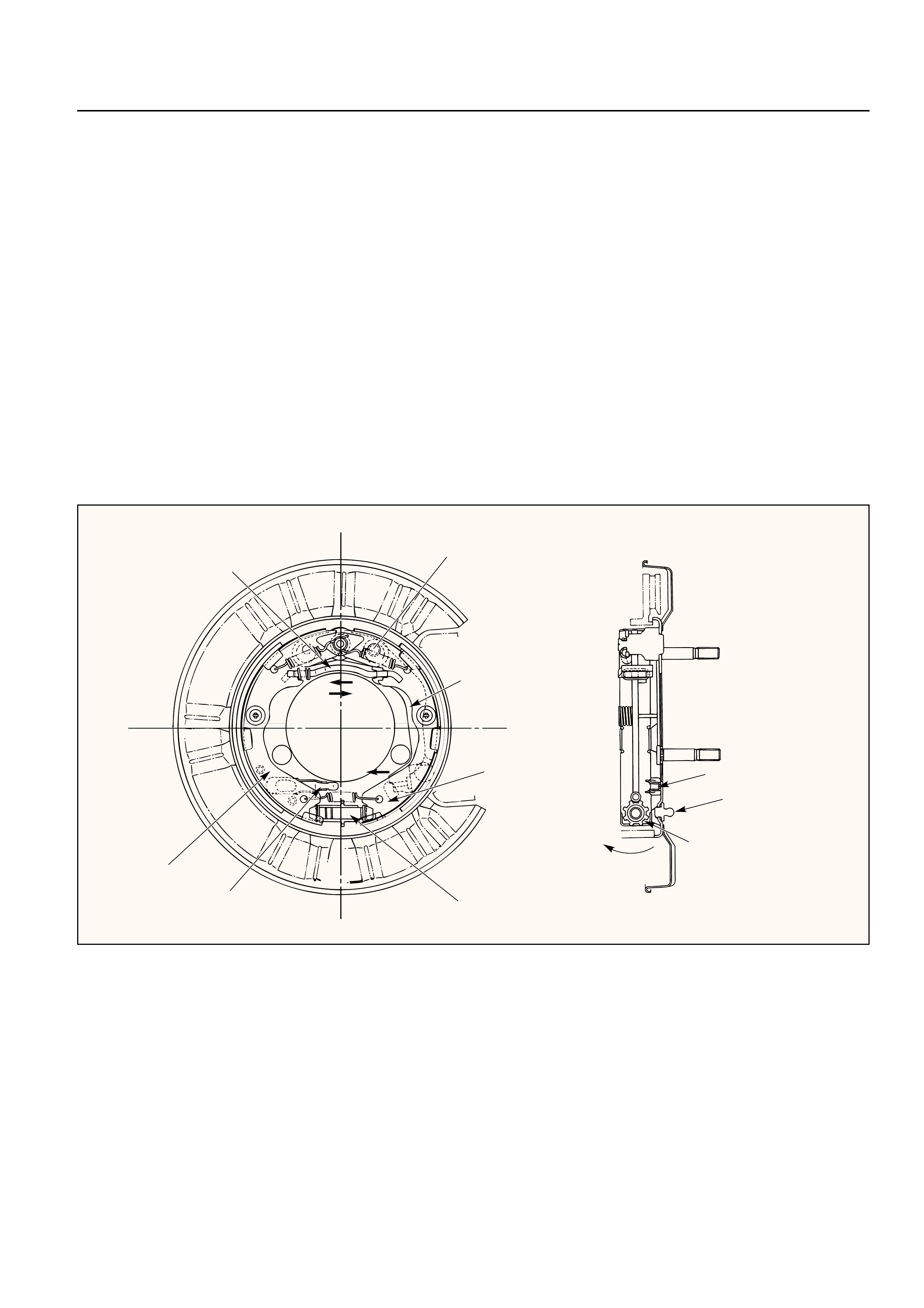
OPERATION
When pulled in the direction “A”, the parking lever presses the secondary shoe against the brake drum
using the lever/shoe joint “B” as a fulcrum and pushes the strut in the direction “C”. The strut, in turn,
presses the primary shoe against the brake drum. Counter force “D” to the primary shoe is transmitted
again to the secondary shoe through the fulcrum “B”. The secondary shoe contacts the drum, thereby
producing braking effect. Clearance which may result from worn parking brake shoe lining can be
adjusted by turning the adjusting screw
Parking lever
Strut
Primary shoe
Parking cable guide Adjusting screw notch
Secondary shoe
DC
A
Fulcrum B
Parking brake cable guide
Adjusting hole plug
Adjusting screw notch
Shoe expanding
direction
Adjusting nut
Equalizer
ON-VEHICLE SERVICE
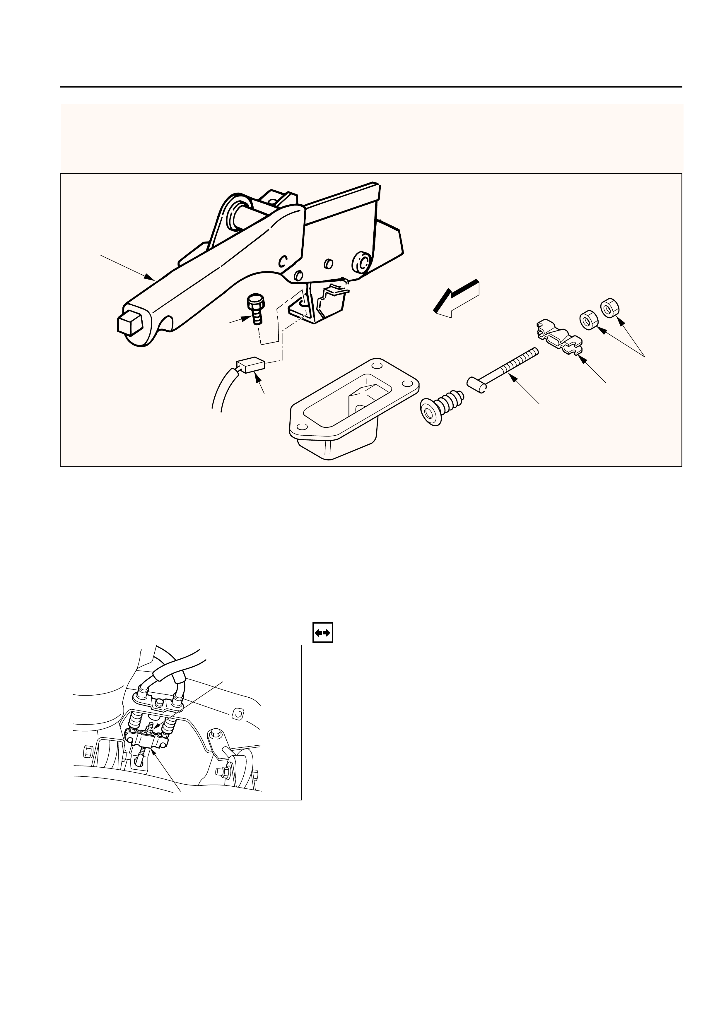
PARKING BRAKE LEVER REPLACEMENT
3
5
1
2
4
6
Removal Steps
1. Ajusting nut
2. Equalizer
3. Bolt
4. Switch connector
5. Parking brake lever
6. Parking brake front cable
Installation Steps
To install, follow the removal steps in the
reverse order.
REMOVAL
1. Ajusting Nut
2. Equalizer
3. Bolt
Remove the center console as described in Body
and Accessories section.
Then remove the fixing bolt.
4. Switch Connector
5. Parking Brake Lever
6. Parking Brake Front Cable
331RW007
331RW008

INSTALLATION
6. Parking Brake Front Cable
5. Parking Brake Lever
•Apply grease (BESCO L-2 or equivalent) to front
cable contact point.
4. Switch Connector
3. Bolt
•Tighten the parking brake lever fixing bolt to the
specified torque.
Bolt Torque N·m (kg·m / lb·ft)
15 (1.5 / 11)
•Install the center console.
2. Equalizer
1. Adjusting Nut

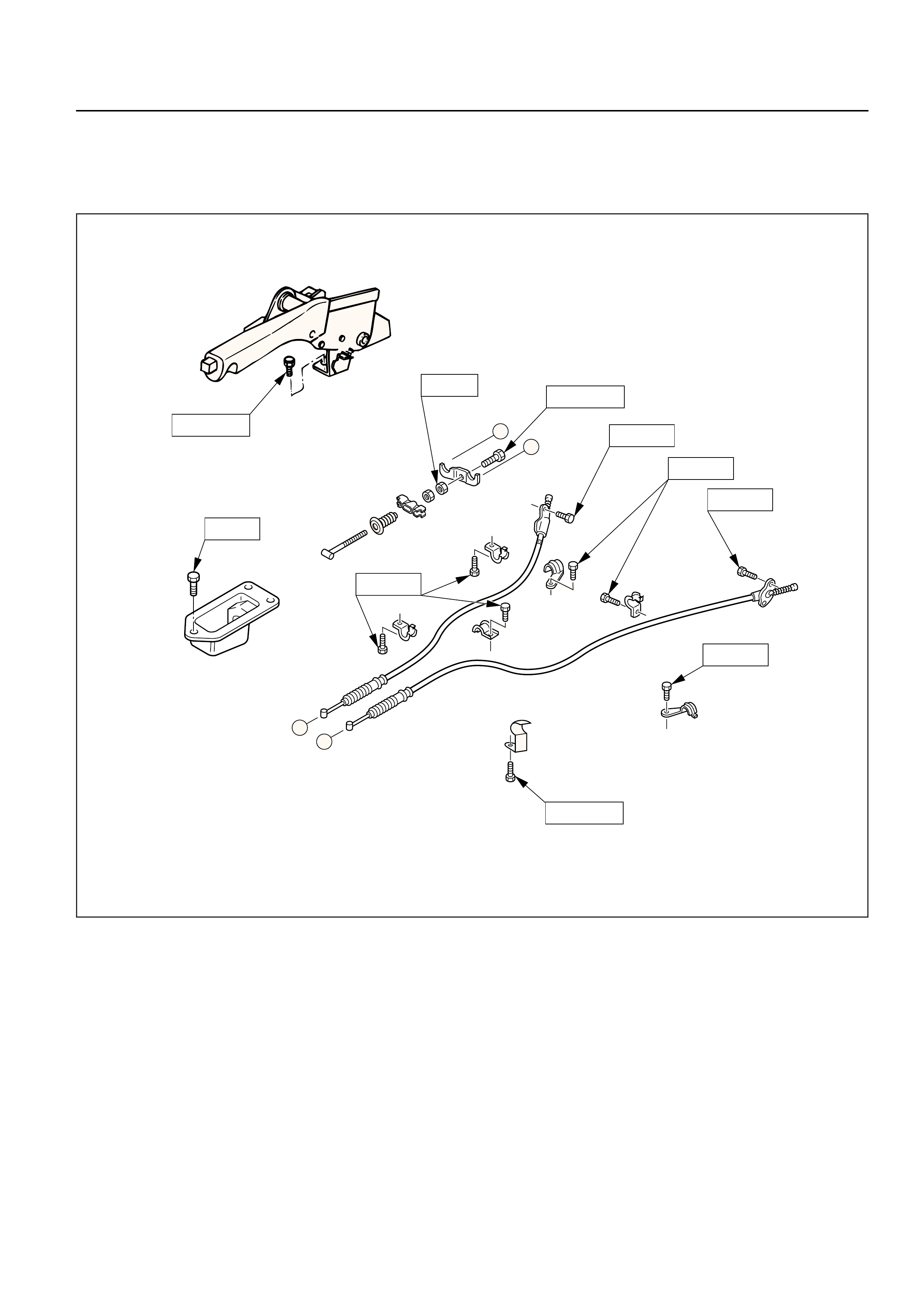
PARKING BRAKE CABLE
5
7
42
3
1
6
7
12 15
13
14
AB
10
8
9
10
11
16
9
8
A
B
Removal Steps
1. Rear wheels
2. Caliper assembly
3. Rotor (Drum)
4. Holding spring
5. Return spring; upper
6. Return spring; lower
7. Shoe assembly
8. Cable fixing bolt
9. Clip
10. Clip
11. Clip
12. Adjust nut
13. Equalizer
14. Bolt
15. Retaining plate
16. Parking brake cable
Installation Steps
To install, follow the removal steps in the
reverse order.
331RW009
INSTALLATION
To install, follow the removal steps in the reverse
order, noting the following points.
15.Parking Brake Cable
•Apply grease (BESCO L-2 or equivalent) to the
connecting portion of the rear cable and equalizer.
12.Adjust Nut
•Tighten the adjust nut to the specified torque.
Adjust Nut TorqueN·m (kg·cm / lb·in)
6 (60 / 52)
•To adjust the parking brake, refer to Parking Brake
Adjustment in this section.
11.Clip
•Tighten the fixing bolt to the specified torque.
Fixing Bolt TorqueN·m (kg·cm / lb·in)
15 (150 / 130)
10.Clip
•Tighten the fixing bolt to the specified torque.
Fixing Bolt TorqueN·m (kg·cm / lb·in)
6.5 (65 / 58)
REMOVAL
1.Rear Wheels
2.Caliper Assembly
•Remove 2 bolts to remove the caliper assembly
from the support bracket. (Refer to Rear Disc
Brakes in Power Assisted Brake System section.)
Temporarily hang the caliper with wire to avoid
stretching the brake hose.
3. Rotor (Drum)
4. Holding Spring
5. Return Spring; Upper
6. Return Spring; Lower
7. Shoe Assembly
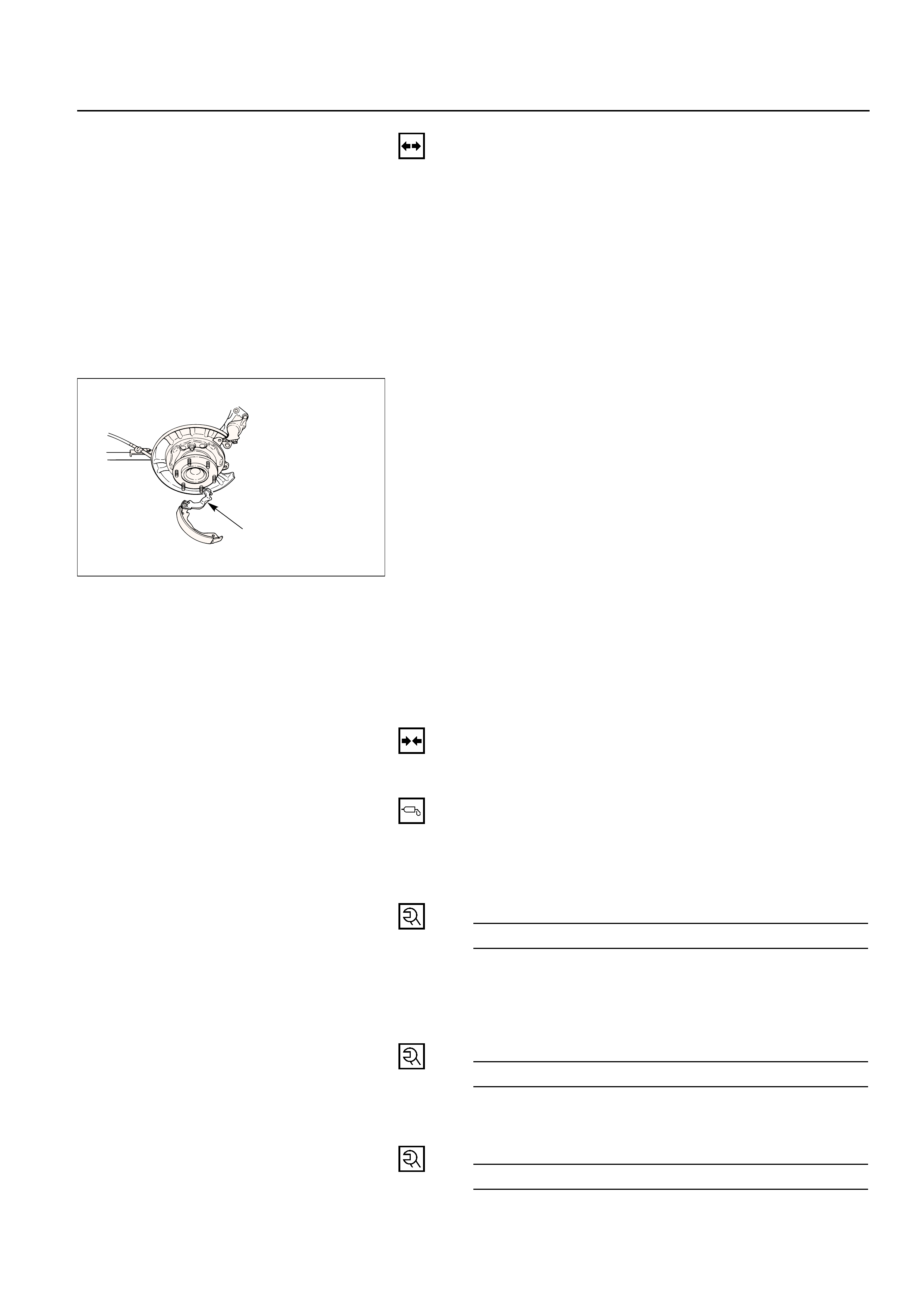
•Remove the brake shoe assembly. Then remove
the parking brake cable from the parking brake
lever.
8. Cable Fixing Bolt
9. Clip
10. Clip
11. Clip
12. Adjust Nut
13. Equalizer
14. Bolt
15. Retaining Plate
16. Parking Brake Cable
Parking brake lever
9. Clip
•Tighten the fixing bolt to the specified torque.
Fixing Bolt Torque N·m (kg·cm / lb·in)
7.8 (78 / 67)
8. Cable Fixing Bolt
•Tighten the cable fixing bolt to the specified
torque.
Cable Fixing Bolt Torque N·m (kg·cm / lb·in)
6.5 (65 / 58)
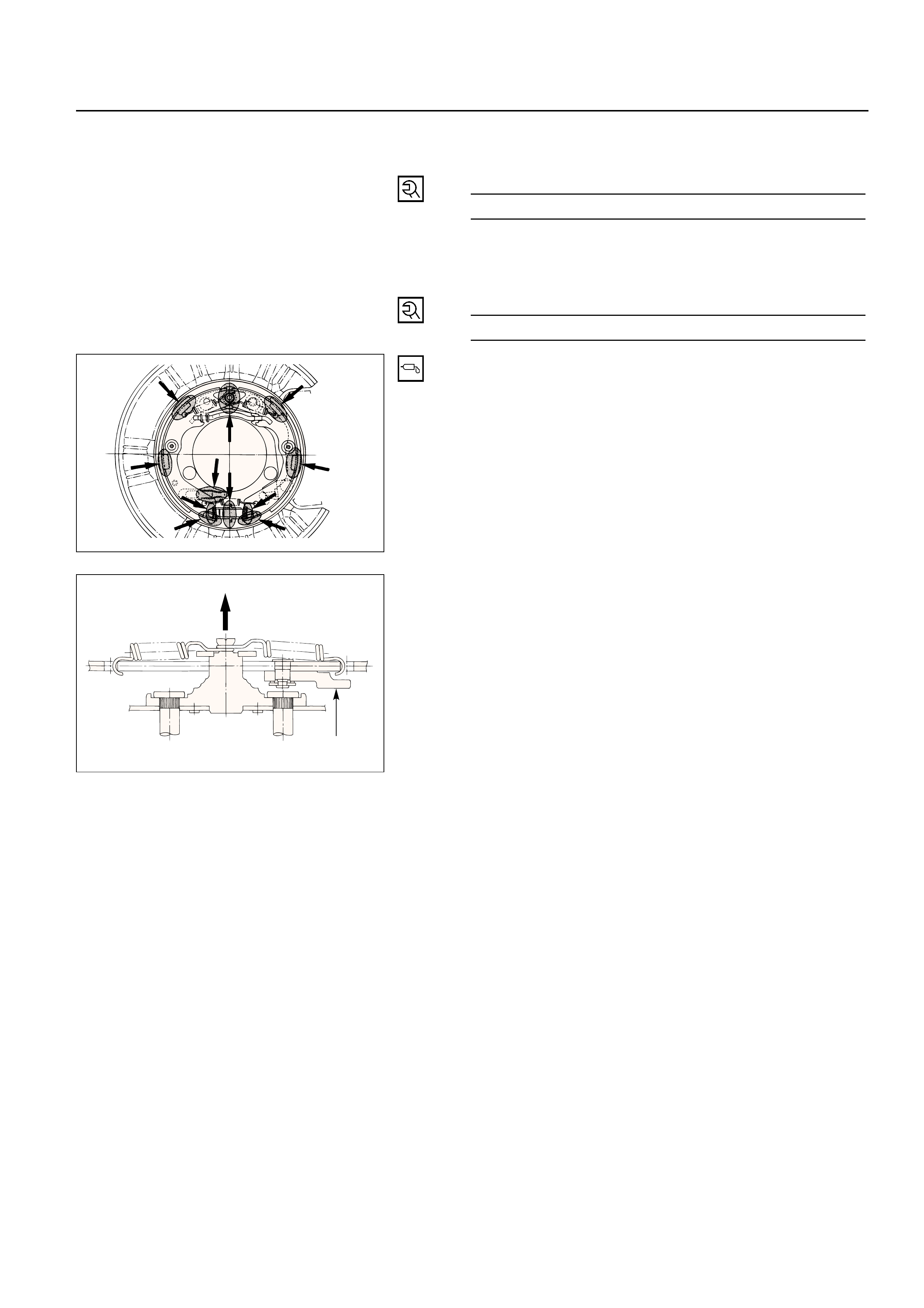
7. Shoe Assembly
•After installation of the shoe and cable assembly,
apply special grease (included in the repair kit) to
the following portions indicated in the left figure.
5. Return Spring; Upper
•The parking brake lever side (secondary side)
return spring must be installed on the outer side
of the primary side return spring.
Outer side
Parking lever