
SECTION 6A - ENGINE MECHANICAL
General Description
Service Information
Service Standard
Servicing
Tightening Torque
Special Tools
Engine Assembly
Engine Mount (RH)
Engine Mount (LH)
Intercooler
Cylinder Head Cover
Intake Manifold
Exhaust Manifold
Turbocharger
Cylinder Head
Cylinder Head Gasket
Camshaft
Timing Gear
Valve Stem Seal, Valve Spring and Adjuster
Valve Clearance Adjustment
Oil Rail and Injector
Crank Case
Crankshaft
Piston and Connecting Rod
Cylinder Block
Oil Pump Assembly
Oil Filter Cartridge
Oil Cooler
Techline
Techline
Techline
Techline
Techline
GENERALDESCRIPTION
Cylinder Head Gasket
The cylinder head gasket is laminated steel sheets.
Three grades of the gasket according to the measured
piston head projection from the cylinder block are
provided to give the engine a minimum compression
ratio fluctuation.
Tightening Method for
Special Bolt
The cylinder head fixing bolts, flywheel bolts and
connecting rod cap fixing bolts are tightened by the
angular Tightening Method.
Piston
Auto-thermatic pistons having steel struts with a 0.4
mm offset from the piston pin center line, are applied to
reduce thermal expansion and resulting engine noise
when the engine is cold.
Bearings
The crankshaft bearings and connecting rod bearings
are of aluminum having a high bearing surface.
These bearings are especially sensitive to foreign
material such as metal scraps. So, it is very important
that the oil ports and other related surfaces are kept
clean and free of foreign material.
Crankshaft bearings are selected for optimum bearing
and journal clearance which reduces vebration and
noise.
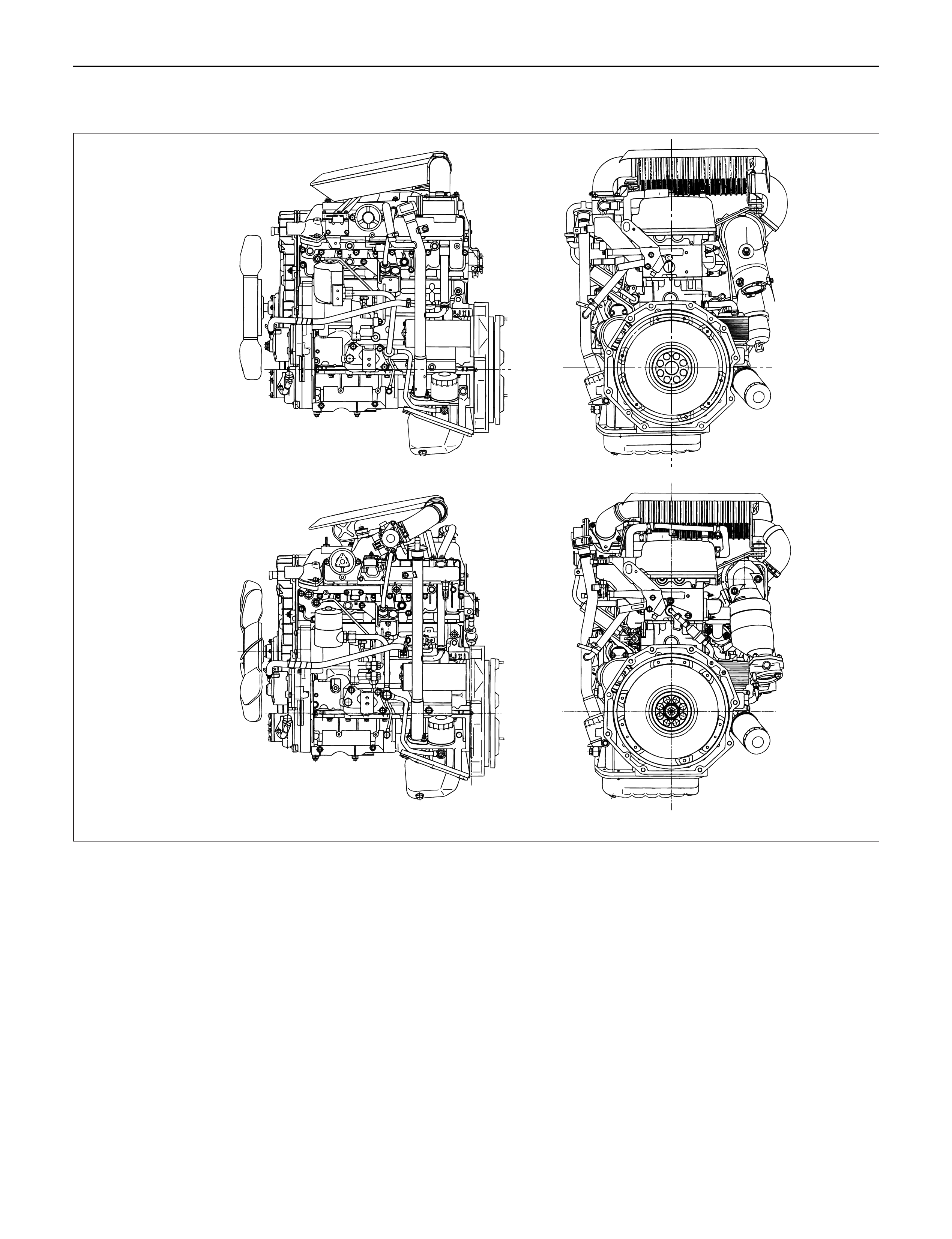
MY1998-2002 Euro-2
MY2003 Euro-3
F06R200004

SERVICE INFORMATION
MAIN DATA AND SPECIFICATION
Engine type Diesel, four cycle water cooled inline
Camshaft type DOHC
Number of cylinders 4
Bore x stroke (mm) 95.4 x 104.9
Total piston displacement (cc) 2999
Compression ratio(to 1) 19.0
MY2003 Euro-3 18.5
Engine weight (dry) N (kg/lb) 2492 (254/560) (A/T)
MY2003 Euro-3 2422 (247/545) (A/T)
2649 (270/593) (M/T)
MY2003 Euro-3 2697 (275/606) (M/T)
Engine idling speed (Reference) RPM 720
Compression pressure kpa (kg/cm2/psi)-rpm 3040 (31/441)-200
Firing order 1-3-4-2
VALVE SYSTEM
Intake valves open at: B.T.D.C. 3 deg.
close at: A.B.D.C. 58 deg.
Exhaust valves open at: B.B.D.C. 57 deg.
close at: A.T.D.C. 5 deg.
Valve clearance (at cold) mm (in)
intake: 0.15 (0.006)
exhaust: 0.25 (0.01)
Oil filter Full flow and bypass combined type
Oil capacity (Original factory fill or rebuilt engine) 9.0 liters
Oil capacity (Service change)
with filter change 6.0 liters
without filter change 5.0 liters
Oil cooler Water cooled type
Inter cooler Air cooled type
Turbocharger method
Control method Wastegate control
Lubrication Pressurised control
Cooling method Coolant cooled
Crankshaft
As tufftriding (Nitrizing treatment) is applied to increase
crankshaft strength, crankpins and journals should not
be reground.
Piston Cooling
An oiling jet device for piston cooling is provided in the
lubricating oil circuit from the cylinder block oil gallery
via a check valve.
Take care not to damage any oiling jet when removing
and installing piston and connecting assembly.
Fuel Injection System
The injection system is oil rail type.
Quick On Start 4 System
QOS4 preheating system which features a quick-on
glow plug with thermometer control of the glowing time
and the afterglow time function, is applied.
Techline

Engine Cooling
Starting System
Cooling system Coolant forced circulation
Radiator (2 tube in row) Tube type corrugated
Heat radiation capacity J/h (kcal/h) 318 x 106(76000)
Heat radiation area m2(ft2) 15.63 (1.454)
Front area m2(ft2) 0.309 (2.029)
Dry weight N (kg/lb) 83 (8.5/18.7)
Radiator cap
Valve opening pressurekPa (kg/cm2/ psi)93.3 – 122.7 (0.95 – 1.25/13.5 – 17.8)
Radiator Coolant Volume lit (Imp.qt./US qt.)M/T2.5 (2.2/2.6)A/T2.4 (2.1/2.5)
Coolant pump Centrifugal impeller type
Pulley ratio( : 1)1.2
Coolant total capacity MY1998-2002 Euro-2: 9.3 Litres
MY2003 Euro-3: 9.8 Litres
Model HITACHI S14-0
Rating
Voltage V 12
Output kW 2.8
Time sec 30
Number of teeth of pinion 9
Rotating direction (as viewed from pinion) Clockwise
Weight (approx.) kg(lb) 5.0(11)
No-load characteristics
Voltage/current V/A 11/160 or less
Speed rpm 4000 or more
Load characteristics
Voltage/current V/A 8.76/300
Torque N·m(kg·m/lb·ft) 7.4 (0.75/5.4) or more
Speed rpm 1700 or more
Locking characteristics
Voltage/current V/A 2.5/1100 or less
Torque N·m(kg·m/lb·ft) 18.6 (1.9/14) or more
Charging System
Model (HITACHI) LR190-750B LR1100 – 731
Rated voltage V 12
Rated output A 90 100
Rotation direction Clockwise
(As viewed from pulley)
Pulley effective diameter mm (in) 69 (2.72)
Weight kg(lb) 5.3(11.7)

SERVICE STANDARD
Engine mm (in)
Parts Items Service standard Service limit Remarks
Cylinder Head
Valve Spring
Valve and
Valve guide
Camshaft
0.075 (0.0030) or less
95.0 (3.740)
45.7 (1.8)
—
241 (54.2)
6.959 – 6.977
(0.27 – 0.272)
6.692 – 6.970
(0.271 – 0.272)
0.023 – 0.056
(0.0009 – 0.0022)
0.03 – 0.063
(0.0011 – 0.0024)
8.0 (0.312)
1.1 (0.0433)
1.2 (0.0472)
1.2 (0.0472)
45°
2.1 (0.0827)
2.1 (0.0827)
0.08 (0.00314)
46.67 (1.8374)
46.77 (1.8413)
29.939 – 29.960
(1.167 – 1.168)
0.02 (0.0008) or less
0.40 – 0.082
(0.0016 – 0.0032)
0.50 (0.0197)
—
44.8 (1.765)
1.6 (0.063)
210 (47.22)
6.92 (0.270)
6.90 (0.269)
0.19 (0.0074)
0.20 (0.0079)
—
1.6 (0.0630)
1.1 (0.0433)
1.1 (0.0433)
—
2.6 (0.1024)
2.6 (0.1024)
2.0 (0.00797)
46.57 (1.8335)
46.67 (1.8374)
29.84 (1.1748)
0.10 (0.0039)
0.12 (0.0047)
Cannot be
reground
Cylinder head lower surface for flatness
Cylinder head height
Free height
Squareness
Spring tension (when assembled) N( lb)
Diameter of Valve stem IN
EX
Valve and valve guide clearance IN
EX
Valve guide upper end height
(Measured from the Cylinder head upper
face)
Valve guide margin
Valve thickness IN
EX
Valve seat contact surface angle
Valve seat contact width IN
EX
End play
Cam lobe height IN
EX
Journal diameter
Runout
Camshaft oil clearance

Parts Items Service standard Service limit Remarks
Tappet
Crankshaft
Piston,
Piston pin,
Piston ring
and
Connecting
rod
32.977 – 32.990
(1.2983 – 1.2988)
0.01 – 0.039
(0.0004 – 0.0015)
0.04 – 0.20
(0.0016 – 0.0079)
0.037 – 0.068
(0.0015 – 0.0027)
0.05 (0.0020) or less
69.917 – 69.932
(2.7526 – 2.7532)
52.915 – 52.930
(2.0933 – 2.0839)
95.320 – 95.349
(3.7527 – 3.7539)
0.11 – 0.92
(0.0043 – 0.0362)
0.25 – 0.40
(0.0098 – 0.0157)
0.20 – 0.35
(0.0079 – 0.0138)
0.10 – 0.30
(0.0039 – 0.0118)
0.05 – 0.09
(0.0020 – 0.0035)
0.03 – 0.07
(0.00118 – 0.00276)
30.995 – 31.000
(1.203 – 1.205)
0.008 – 0.020
(0.0003 – 0.00079)
0.005 – 0.018
(0.0002 – 0.0007)
0.08 (0.031) or less
0.05 (0.0020) or less
0.230 (0.0091)
0.022 – 0.042
(0.0009 – 0.0017)
32.950 (1.2972)
0.10 (0.0039)
0.30 (0.00118)
0.11 (0.0043)
0.08 (0.0031)
69.91 (2.7524)
52.90 (2.0827)
—
—
1.5 (0.0590)
1.5 (0.0590)
1.5 (0.0590)
0.15 (0.0059)
0.15 (0.0059)
30.97 (1.2078)
0.05 (0.0020)
0.04 (0.0016)
0.20 (0.00787)
0.15 (0.0059)
0.35 (0.0138)
0.0060
(0.0024)
Uneven
wear limit
0.05 (0.002)
Uneven
wear limit
0.08 (0.0031)
Per 100
(3.94)
Per 100
(3.94)
Outside diameter
Oil clearance
Thrust clearance
Main bearing oil clearance
Crankshaft runout
Main journal diameter
Crank pin diameter
Piston diameter
Piston clearance
Piston ring gap 1st
2nd
Oil
Piston ring clearance 1st/2nd
Oil
Piston pin diameter
Piston pin clearance
(Between connecting rod and piston pin)
Piston pin clearance
(Between piston and piston pin)
Connecting rod alignment Bend
Twist
Connecting rod thrust clearance
Oil clearance
(Between crank pin and Connecting rod)
mm (in)
mm (in)
Parts Items Service Standard Service Limit Remarks
Cylinder
Block Warpage
(Upper surface of the cylinder head)
Cylinder Bore Diameter
—
95.421 – 95.450
(3.7567 – 3.7579)
0.20 (0.0079) —
Balance
Shaft Bore
Cylinder Block (right side) Front
Centre
Rear
Crankcase (left side) Front
Centre
Rear
50.000 – 50.030
(1.9685 – 1.9696)
50.000 – 50.030
(1.9685 – 1.9696)
13.020 – 13.044
(0.5126 – 0.5135)
51.000 – 51.021
(2.0079 – 2.0087)
46.00 – 46.021
(1.8110 – 1.8119)
13.020 – 13.044
(0.5126 – 0.5135)
— —
Engine Cooling
Parts Items Service Standard Service Limit Remarks
Thermostat Valve opening temperature
Valve full open temperature and lift
83 – 87 °C
(181 – 189 °F)
More than
9.5 mm (0.374 in) at
100 °C (212 °F)
— —
Radiator Cap Valve opening pressure 88.2 – 117.6 kPa
(12.8 – 17.0 psi) — —
SERVICING
Servicing refers to general maintenance procedures to
be performed by qualified service personnel.
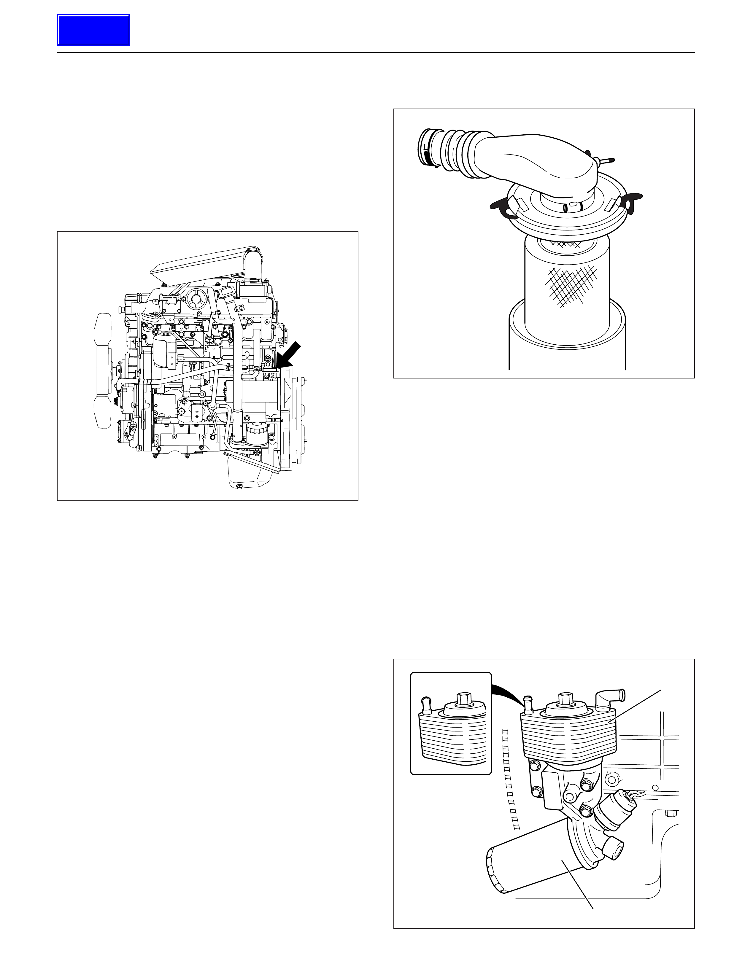
MODEL IDENTIFICATION
Engine Serial Number
The engine number is stamped on the rear left hand
side of the cylinder body.
AIR CLEANER
Oil Wetted (Viscous) Type Paper Element.
The air cleaner has an oil wetted paper element. No
servicing is required until the replacement interval is
reached.
Never attempt to clean the element, no matter how dirty
it may appear. The element is designed to provide
normal filtering efficiency until it becomes due for
replacement.
Refer to the Item “Service and Maintenance” in the
Owner’s and Driver’s Manual for general service
information.
LUBRICATING SYSTEM
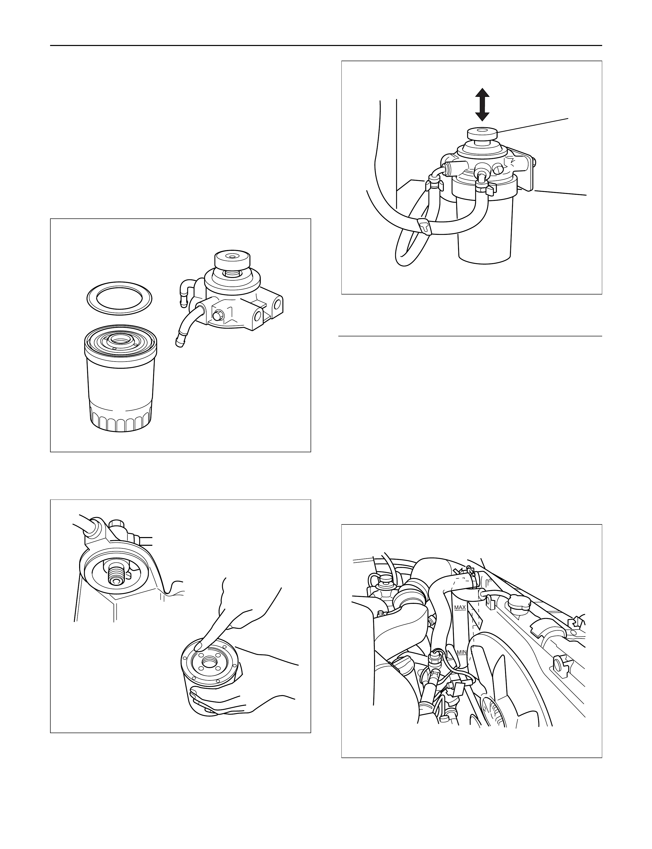
Main Oil Filter (Cartridge Type Paper Element)
Replacement Procedure
1. Loosen the drain plug to drain the engine oil.
2. Wait a few minutes and then retighten the drain
plug.
3. Loosen the used oil filter (2) by turning it counter-
clockwise with the filter wrench.
4. Clean the oil filer gasket fitting face.
This will allow the new oil filter to seat properly.
5. Apply a light coat of engine oil to the O-ring.
6. Turn the new oil filter until the filter O-ring is fitted
against the sealing face.
7. Use the filter wrench to turn the filter additional one
and 1/4 turns.
Filter Wrench: 5-5540-0203-0
012RW115
012RW062
MY2003 Euro-3
1
2
050R200001
Techline
8. Check the engine oil level and replenish to the
specified level if required.
9. Start the engine and check for oil leakage from the
main oil filter.
FUEL SYSTEM
Fuel filter
Replacement Procedure
1. Loosen the used fuel filter by turning it
counterclockwise with the filter wrench.
Filter Wrench : 5-8840-0203-0
2. Clean the filter cover fitting faces.
This will allow the new fuel filter to seat properly.
3. Apply a light coat of engine oil to the O-ring.
4. Turn the fuel filter until the sealing face comes in
contact with the O-ring.
5. Turn the fuel filter with a filter wrench 2/3 of a turn
until sealed.
Filter Wrench: 5-8840-0203-0
Legend
(1) Priming pump
6. Operate the priming pump until the air is discharged
completely from fuel system.
NOTE: The use of an Isuzu genuine fuel filter is
strongly recommended.
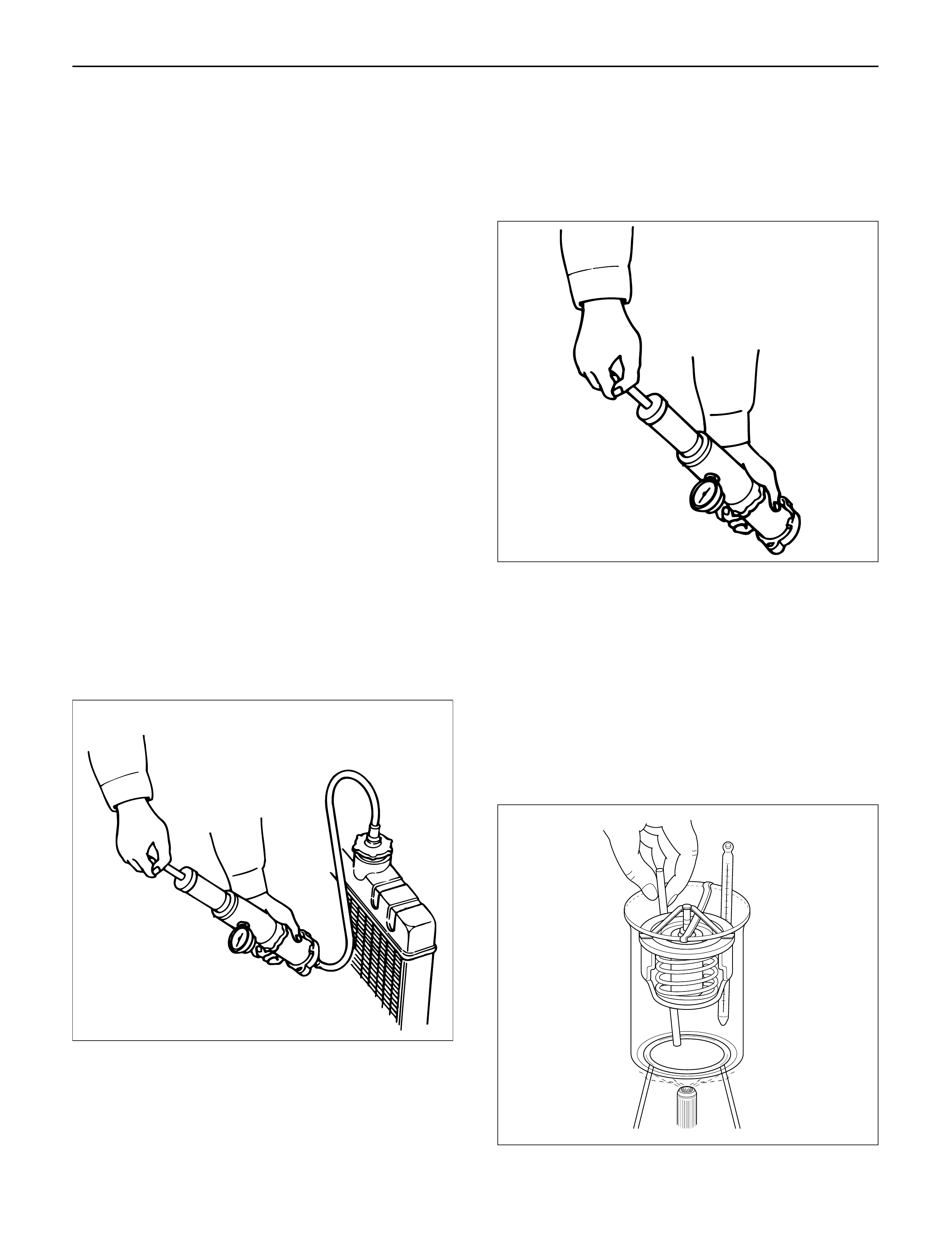
COOLING SYSTEM
Coolant Level
Check the coolant level and replenish the radiator
reserve tank as necessary.
If the coolant level falls below the “‘MIN” line, carefully
check the cooling system for leakage. Then add
enough coolant to bring the level up to the “MAX” line.
NOTE: Do not overfill the reserve tank.
012RW112
012RW078
1
012RW111
012RW080
Remove the radiator filler cap only when absolutely
necessary.
Always check the coolant level when the engine is cold.
Always refer to the chart at the left to determine the
correct cooling water to antifreeze solution mixing ratio.
Cooling System Inspection
Install a radiator filler cap tester to the radiator. Apply
testing pressure to the cooling system to check for
leakage.
The testing pressure must not exceed the specified
pressure.
Testing Pressure: 196 kPa (2 kg/cm2/28.45 psi)
Radiator Cap Inspection
The radiator filler cap is designed to maintain coolant
pressure in the cooling system at 103 kPa (1.05
kg/cm2/15 psi).
Check the radiator filler cap with a radiator filler cap
tester.
The radiator filler cap must be replaced if it fails to hold
the specified pressure during the test procedure.
Radiator Filler Cap Pressure Valve: 88.2 – 117.6 kPa
(0.899 – 1.199 kg/cm2/12.8 – 17.1 psi)
Negative Valve (Reference): 1.0 – 3.9 kPa
(0.01 – 0.04 kg/cm2/0.14 – 0.57 psi)
Thermostat Operating Test
1. Completely submerge the thermostat in water.
2. Heat the water.
Stir the water constantly to avoid direct heat being
applied to the thermostat.
3. Check the thermostat initial opening temperature.
Thermostat Initial Opening Temperature:
83 – 87°C (181 – 189°F)
4. Check the thermostat full opening temperature.
Thermostat Full Opening Temperature:
100°C (212°F)
Valve Lift at Fully Open Position: 9.5 mm (0.374
in)
110RS005
110RS006
031RS003
COOLANT SPECIFICATION
50% water and 50% coolant conforming to Holden
HN2217 specification.
COOLANT CAPACITY
MY1998-2002 Euro-2: Approximately 9.3 litres
MY2003 Euro-3: Approximately 9.8 litres
.
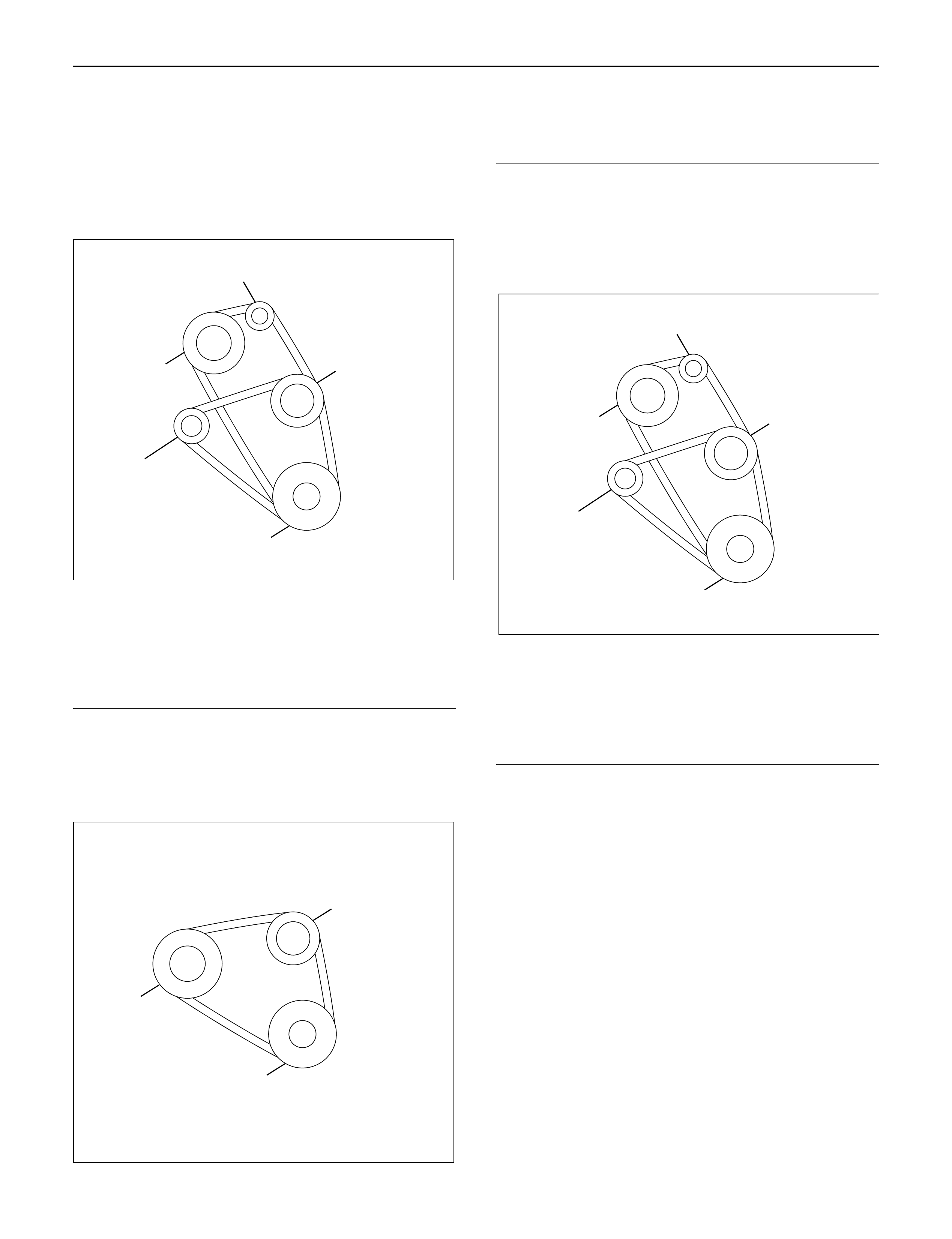
Drive Belt Adjustment
Check the drive belt tension
Depress the drive belt mid-portion with a 98 N (10 kg/
22 lb) force.
Drive Belt Deflection: 10 mm (0.39 in)
Check the drive belt for cracking and other damage.
Legend
(1) Crankshaft pulley
(2) Generator pulley
(3) Cooling fan pulley
(4) A/C compressor pulley
(5) Belt tensioner pulley
Cooling Fan Pulley Drive Belt
Fan belt tension is adjusted by moving the generator.
Depress the drive belt mid-portion with a 98 N (10 kg/
22 lb) force.
Legend
(1) Crankshaft pulley
(2) Generator pulley
(3) Cooling fan pulley
Compressor Pulley Drive Belt
Move the tensioner pulley as required to adjust the
compressor drive belt tension.
Depress the drive belt mid-portion with a 98 N (10 kg/
22 lb) force.
Legend
(1) Crankshaft pulley
(2) Generator pulley
(3) Cooling fan pulley
(4) A/C compressor pulley
(5) Belt tensioner pulley
5
3
2
4
1
012RW110
3
2
1
012RW084
5
3
2
4
1
012RW110
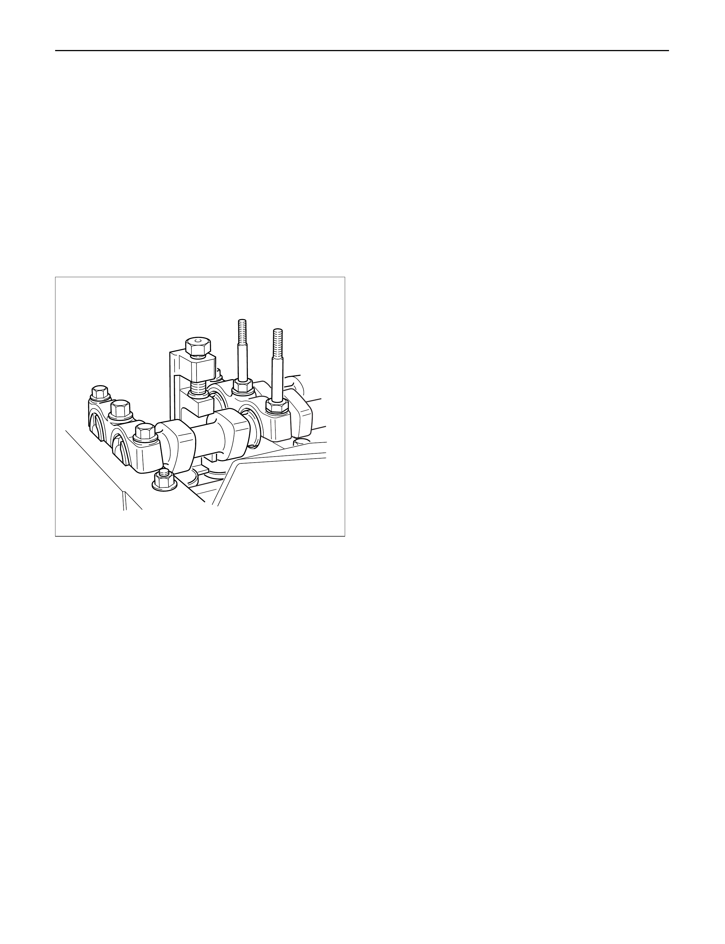
VALVE CLEARANCE ADJUSTMENT
1. Install 2.80 mm valve adjuster (shim) first when
reassembling the engine.
Thickness mark faces down.
2. Measure the valve clearance after installing cam
carrier assy with camshafts.
3. Change the adjuster using a special tool when the
clearance is out of tolerance.
Valve Clearance Adjusting Tool: 5-8840-2590-0
VALVE CLEARANCE (When cold condition)
Inlet 0.15 ± 0.05 mm
Exh 0.25 ± 0.05 mm
COMPRESSION PRESSURE
MEASUREMENT
1. Start the engine and allow it to idle until the coolant
temperature reaches 70 – 80°C (158 – 176°F).
2. Remove the following parts.
•Glow plugs
•Fuel cut solenoid connector
•QOS (Quick-On Start System) fuse in the fuse
box.
3. Set the adapter and compression gauge to the No.
1 cylinder glow plug hole.
Compression Gauge
(with Adapter): 5-8840-2008-0
4. T urn the engine over with the starter motor and take
the compression gauge reading.
Compression Pressure at 200 rpm
Standard: 3040 kPa (31 kg/cm2/441 psi)
Limit: 2160 kPa (22 kg/cm2/313 psi)
5. Repeat the procedure (Steps 3 and 4) for the
remaining cylinders.
QUICK-ON START 4 SYSTEM
Quick-On Start System Inspection Procedure
1. Disconnect the ECT-sensor connection around the
thermostat outlet pipe.
2. Turn the starter switch to the “ON” position.
If the Quick-On Start 4 System is operating
properly, the glow relay will make a clicking sound
within seven seconds after the starter switch is
turned on.
3. Measure the glow plug terminal voltage with a
circuit tester immediately after turning the starter
switch to the “ON” position.
Glow Plug Terminal Voltage: approx. 12V
NOTE: Electrical power to the quick-on start system will
be cut after the starter has remained in the “ON”
position for twenty seconds.
Turn the starter switch to the “OFF” position and back
to the “ON” position.
This will reset the Quick-On Start 4 System.
014RW150
TIGHTENING TORQUE
Timing Gear Case, Timing Gear N·m (kg·m/lb·ft)
75(7.6/55)
Apply engine oil to
thread and seat
8(0.8/69lb•in)
20(2.0/14)
51(5.2/38)
25(2.5/18)
020R200001
Cylinder Head, Flywheel, Crank Case, Oil Pan N·m (kg·m/lb·ft)
012R200008
1st
49N•m(5.0kg•m/36 Ib ft)
167(17.0/123)
8(0.8/69lb•in)
20(2.0/14)
20(2.0/14)
30(3.1/22)
24(2.4/17)
2nd
60°
1st
59N•m(6.0kg•m/43 Ib ft)
Apply engine oil to thread
Apply engine oil to thread
Apply engine oil to thread
2nd
60°-90°
3rd
60°-90°
1st
29N•m(3.0kg•m/22 Ib ft)
2nd
45°-60°
3rd
60°
22(2.2/16)
Intake / Exhaust Manifold N·m (kg·m/lb·ft)
025R200009
MY2003 Euro-3
MY2003 Euro-3
20(2.0/14)
20(2.0/14)
20(2.0/14)
22(2.2/16)
22(2.2/16)
30(3.1/22)
27(2.8/20)
30(3.1/22)
20(2.0/14)

Timing Pulley N·m (kg·m/lb·ft)
020R200002
20(2.0/14)
40(4.1/30) 60°-90°
1st 2nd
10(1.0/87lb•in)
20(2.0/14)
50(5.1/37)
20(2.0/14)
9(0.9/78lb•in)
9(0.9/78lb•in)
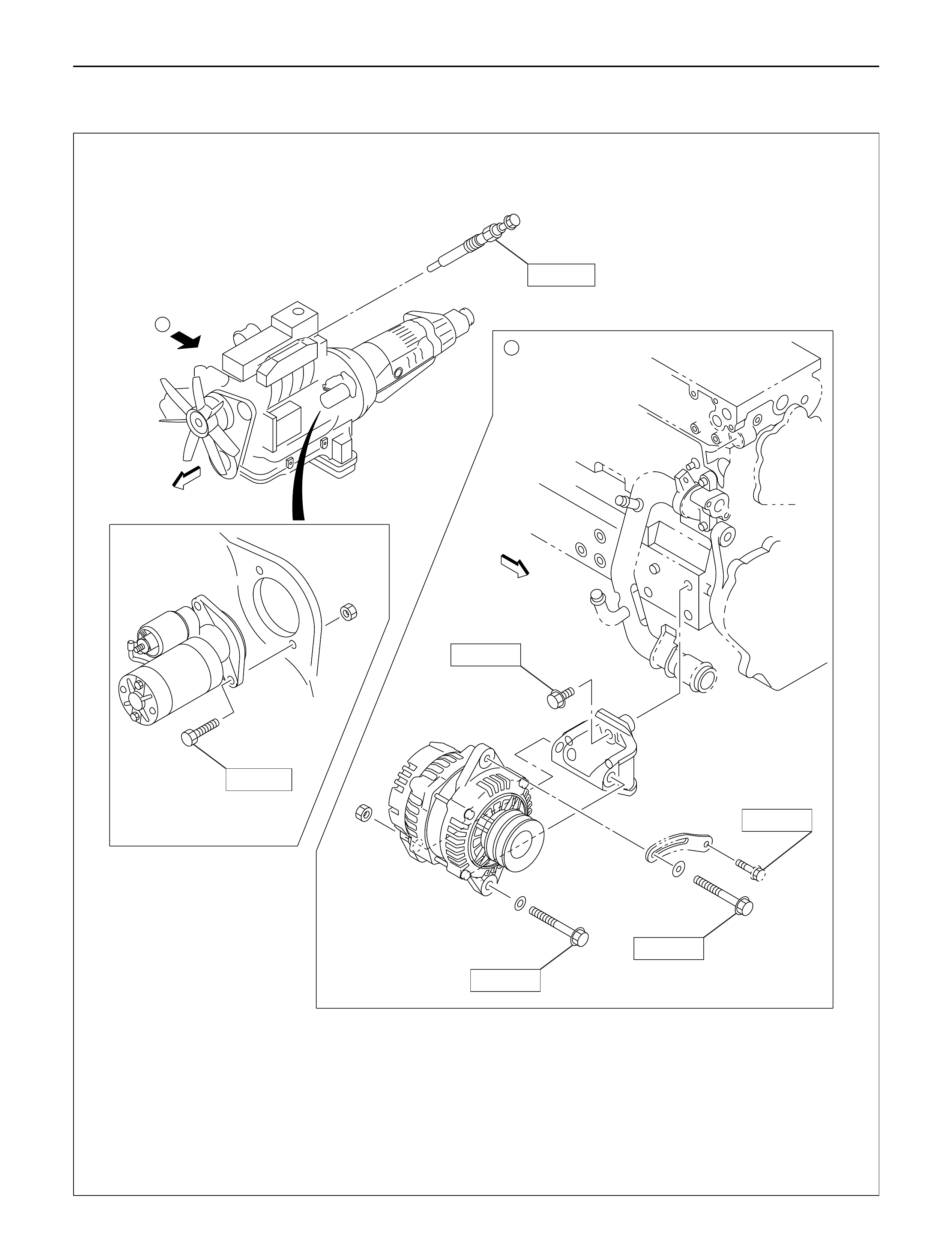
Engine Electricals N·m (kg·m/lb·ft)
060R200291
A
A
15(1.5/11)
85(8.7/63)
40(4.1/30)
40(4.1/30)
24(2.4/17)
20(2.0/14)
Injector
N.m (kg m/lb ft)
20N.m (2.0kg.m/14 lb.ft)
7N.m (0.7kg.m/61 lb.in)
20N.m (2.0kg.m/14 lb.ft)
Recheck tightening torque
after tightening the oil rail
Apply engine oil to the
stud bolt threads
Tighten 30N.m (3.1kg.m/22lb.ft)
Loosen then tighten again to
25N.m (2.5kg.m/18 lb.ft)
Apply engine oil
to both sides
25N.m (2.5kg.m/18ft.lb) Without
spacer type
E06R200027
With
spacer type
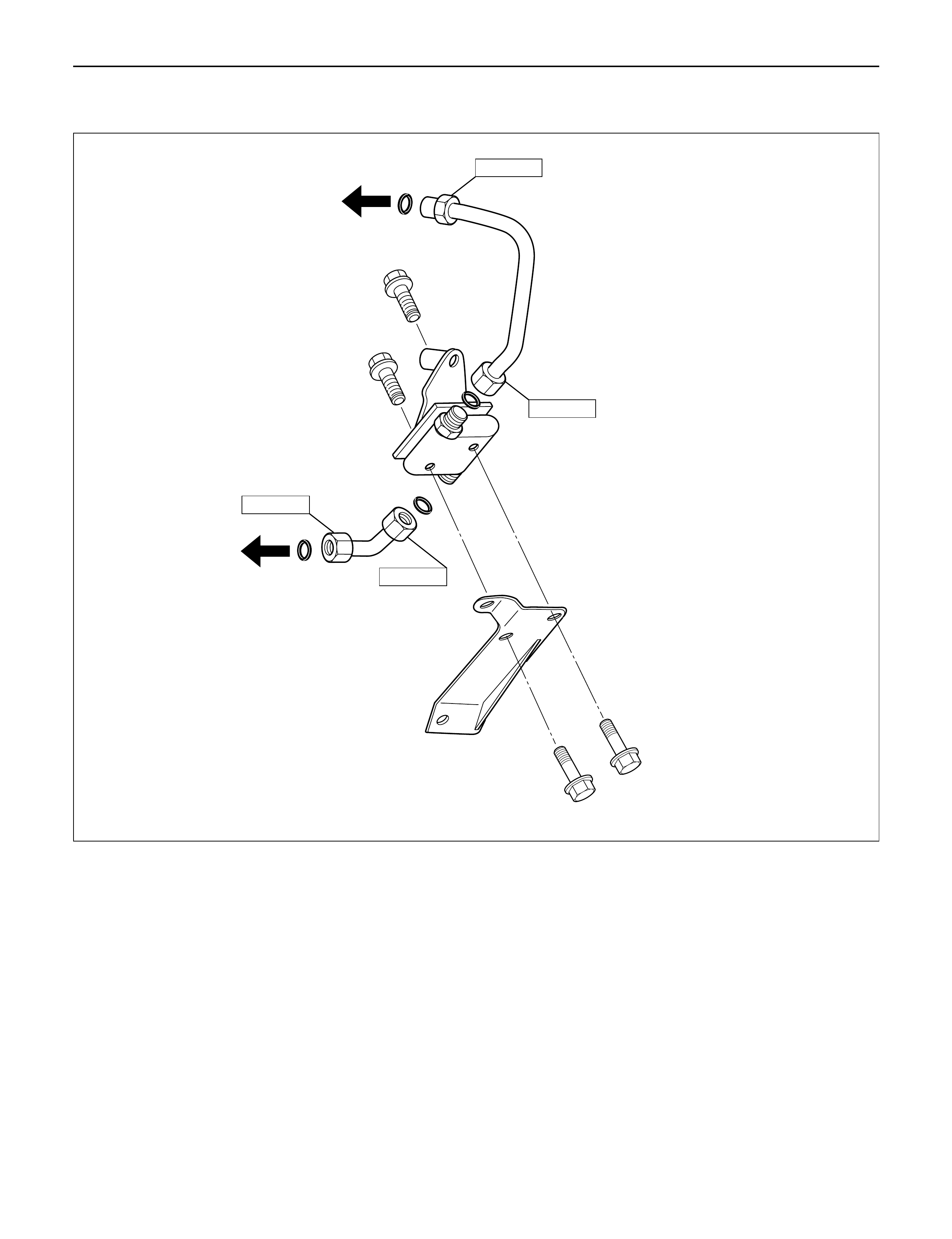
High Pressure Oil Pipe N·m (kg·m/lb·ft)
78(8.0/58)
78(8.0/58)
78(8.0/58)
78(8.0/58)
052R200003
Air Duct and Intercooler MY1998-2002 Euro-2 N·m (kg·m/lb·ft)
3(0.3/26lb•in)
4(0.4/35lb•in)
20(2.0/14)
4(0.4/35lb•in)
20(2.0/14)
135R200004
Air Duct and Intercooler MY2003 Euro-3 N·m (kg·m/lb·ft)
4(0.4/35lb•in)
4(0.4/35lb•in)
3(0.3/29lb•in)
20(2.0/14)
135R200005
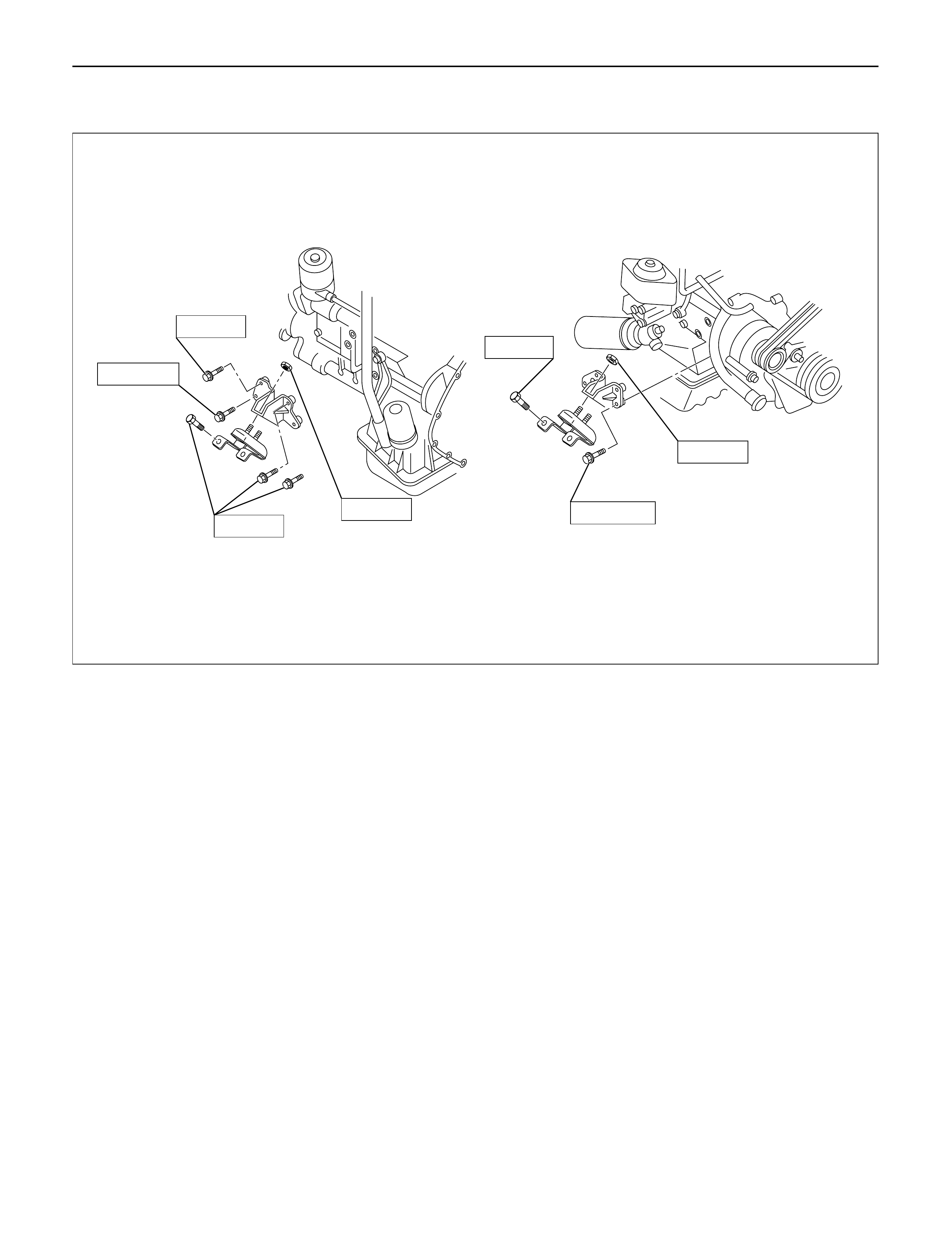
Engine Mount Bracket N·m (kg·m/lb·ft)
50(5.1/37)
50(5.1/37) 127(13.0/94)
127(13.0/94)
40(4.1/30)
40(4.1/30)
40(4.1/30)
022R200002
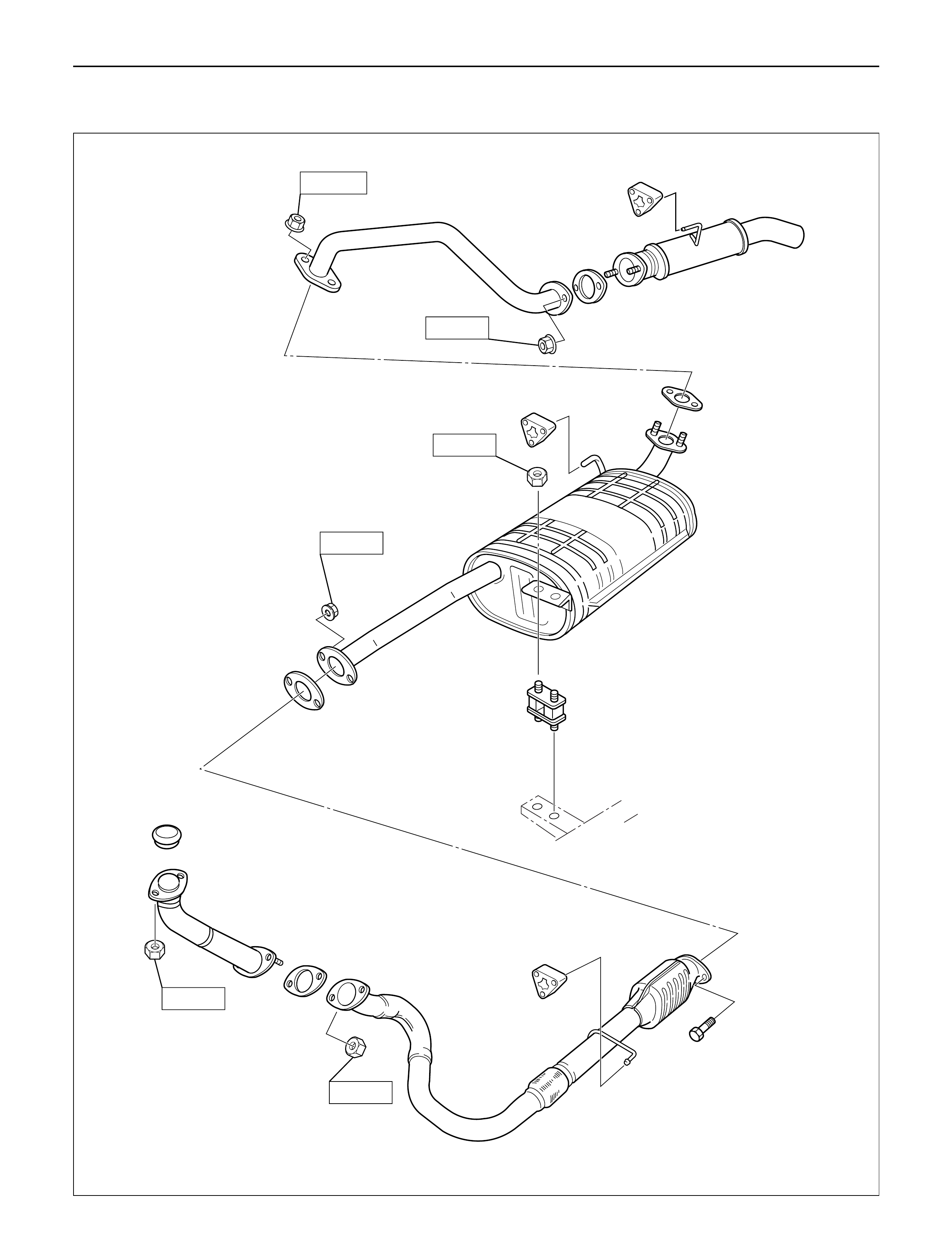
Exhaust System N·m (kg·m/lb·ft)
150R200031
43(4.4/32)
43(4.4/32)
16(1.6/12)
43(4.4/32)
67(6.8/49)
43(4.4/32)
901RT034
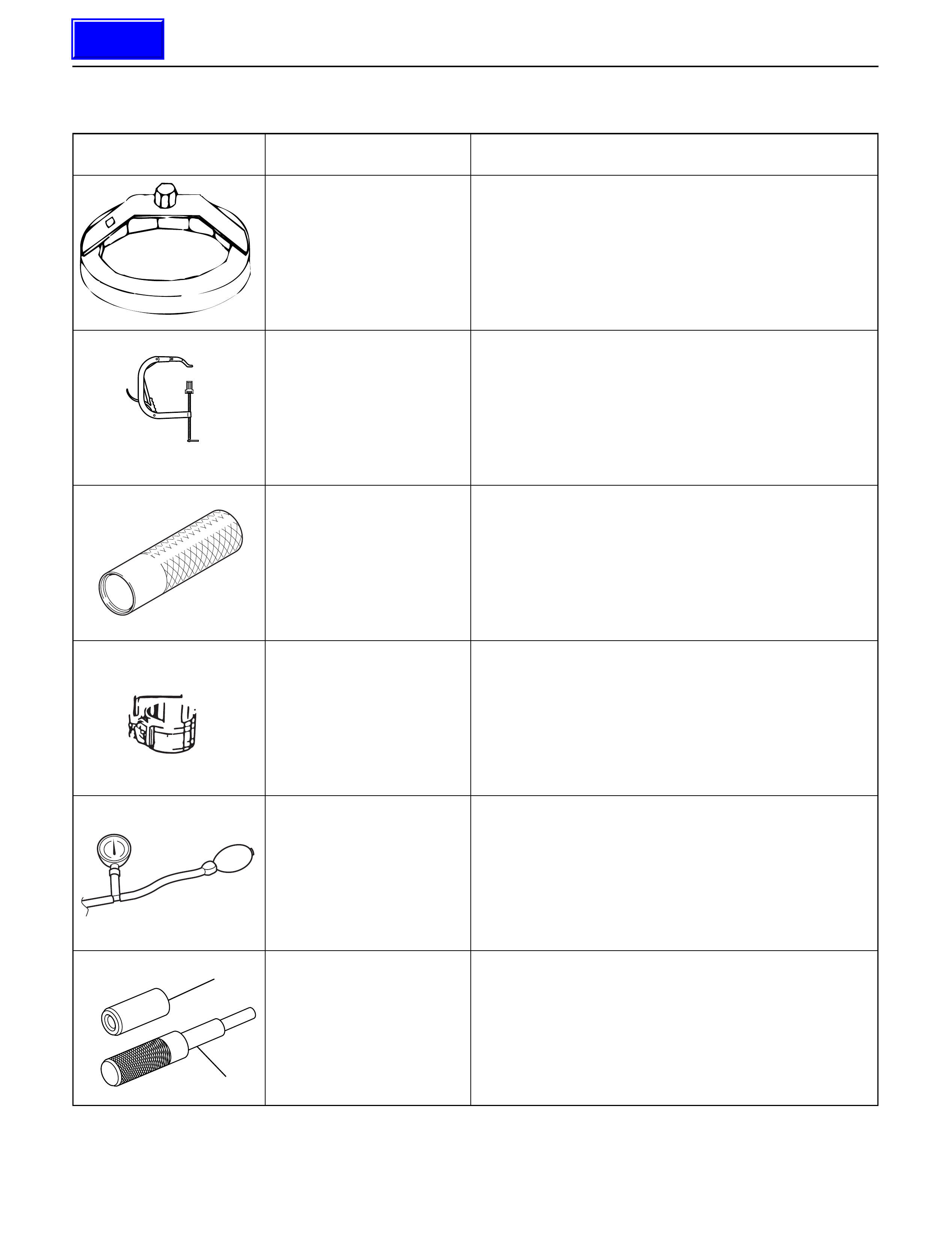
Illustration Tool No. Tool Name
SPECIALTOOLS
5-8840-0203-0 Filter Wrench
5-8840-2441-0 Valve Spring Compressor
5-8840-2033-0 Stem Seal Installer
5-8840-9018-0 Piston Ring Compressor
5-8840-0075-0 Turbocharger Pressure Gauge
9-8523-1212-0 Valve Guide Replacer
F06RV038
5884020330
901LX017
901RX00001
1
2
901RW182
Techline
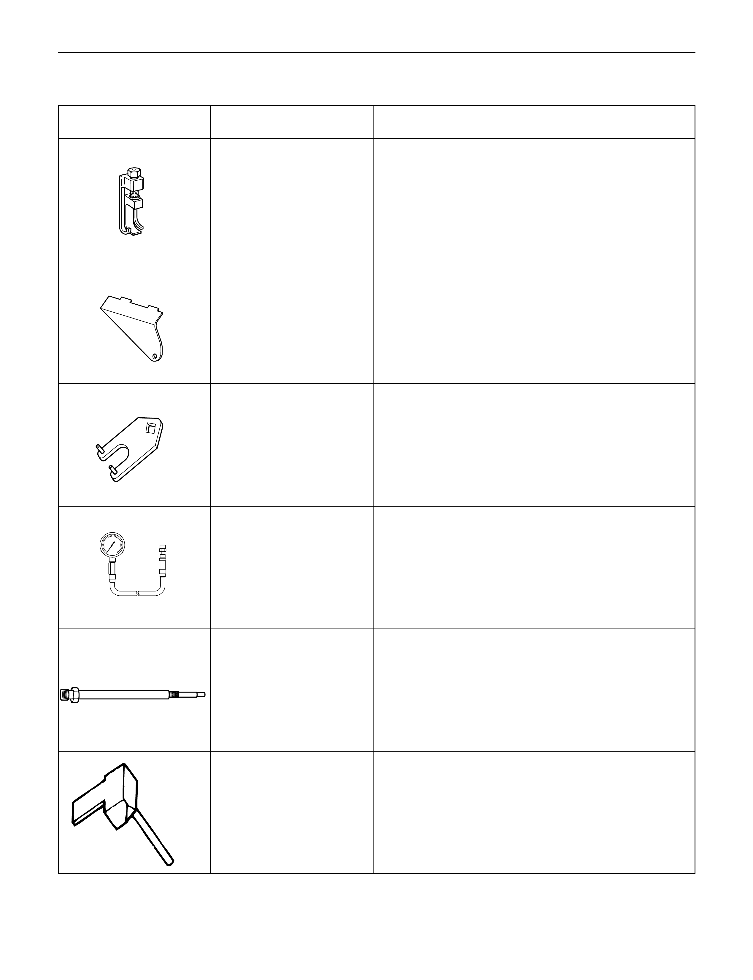
Illustration Tool No. Tool Name
SPECIAL TOOLS
5-8840-2590-0 Valve Clearance Adjusting Tool
5-8840-2592-0 Camshaft Stopper
5-8840-2591-0 Camshaft Gear Tool
5-8840-2675-0
5-8531-7002-0
Compression Gauge
Adapter: Compression Gauge
5-8840-2153-0 Seal Cutter
F06RW056
F06RV037
901LX057
901LX056
F06RW057
901RT042
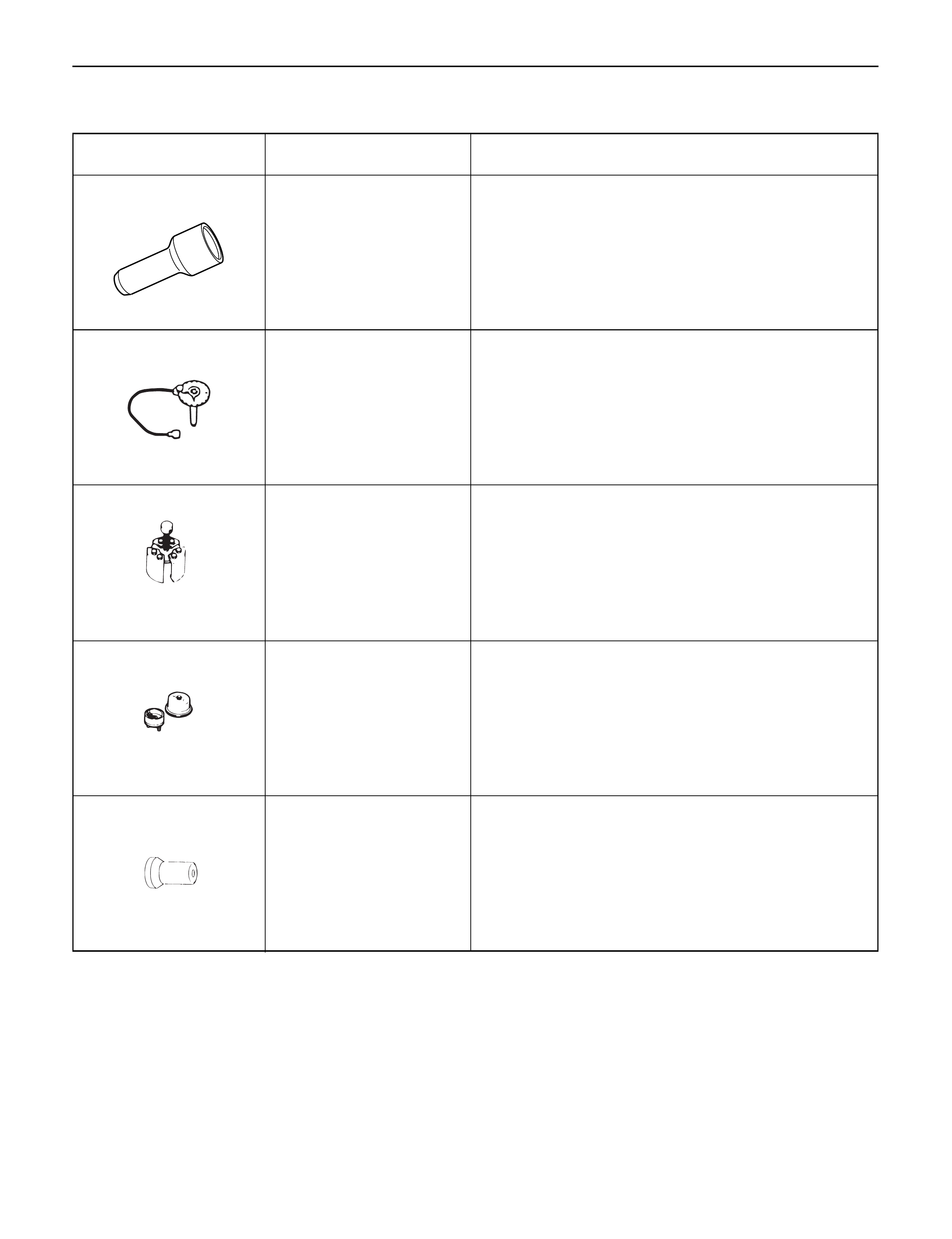
Illustration Tool No. Tool Name
SPECIAL TOOLS
5-8840-0266-0 Angle Gauge
5-8840-2360-0 Rear Oil Seal Remover
5-8840-2359-0 Rear Oil Seal Installer
5-8840-2061-0 Front Oil Seal Installer
901LX030
901LX040
901LX025
901LX039
901RV061
9-8522-0021-0 Crankshaft Gear Installer
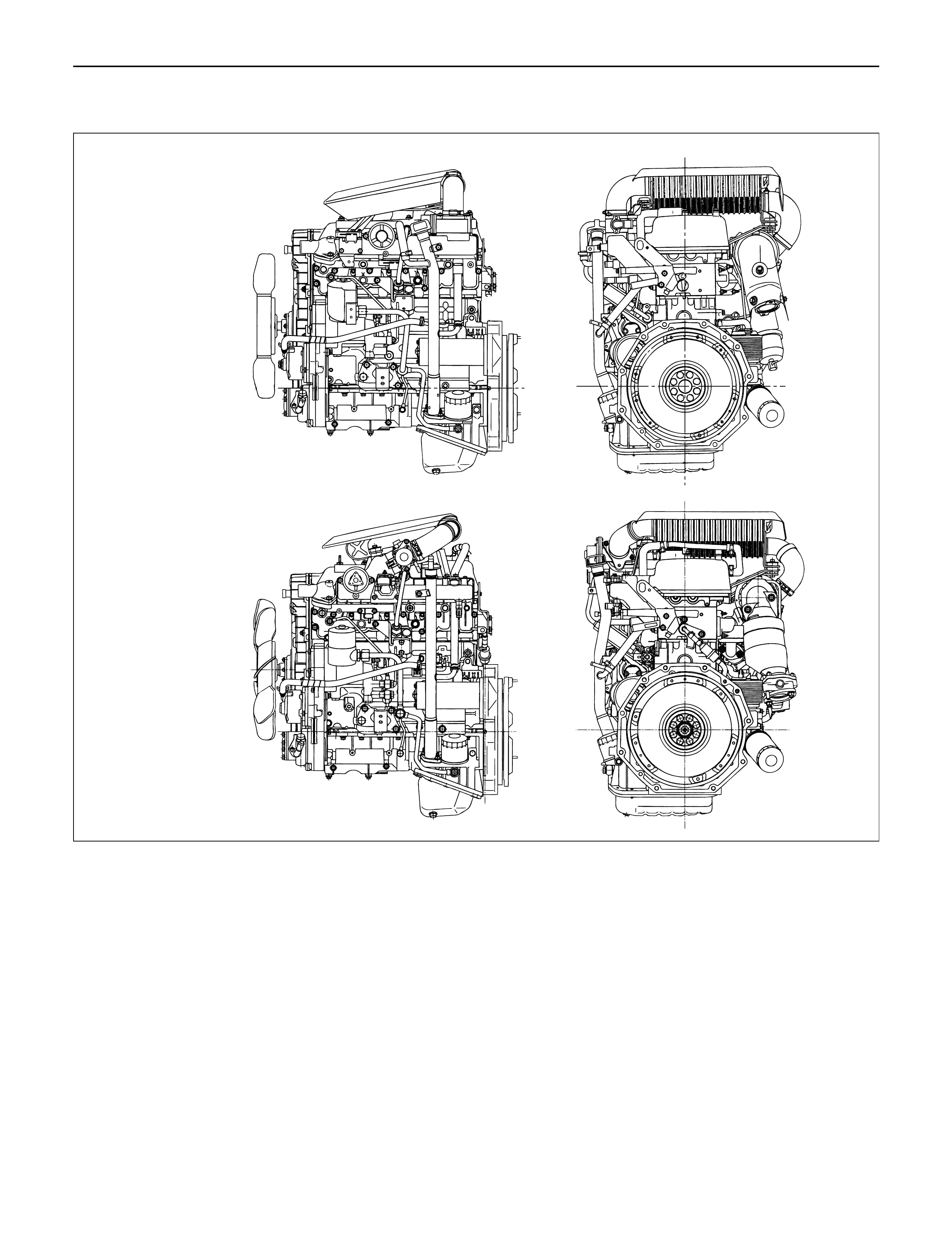
ENGINE ASSEMBLY
MY1998-2002 Euro-2
MY2003 Euro-3
F06R200004
REMOVAL
1.Remove battery.
2.Drain engine coolant
3.Disconnect window washer hose and remove
engine hood.
4.Radiator Hose
1)Disconnect upper and lower hoses from engine
side.
5.Fan Shroud
1)Disengage clips and remove upper and lower
fan shrouds.
6.Cooling Fan Assembly
1)Remove cooling fan assembly fixing nuts,
cooling fan assembly.
7.Radiator Assembly
1)Remove bracket and radiator assembly.
8.Air Cleaner Cover & Air Duct
9.Intercooler Assembly
1)Refer to “Intercooler” in this manual.
10. Engine Ground Cable
1) Disconnect ground cable from A/C compressor
bracket.
11. AC Generator Harness
1) Disconnect B terminal and harness connector
from AC generator .
12. A/C Compressor Assembly
1) Disconnect magnetic clutch harness connector.
2) Remove A/C compressor fixing bolt (rear under
side of compressor).
3) Remove fixing bolts (upper and front lower side
of compressor) and set A/C compressor
assembly with pipe lines on battery carrier.
13Vacuum Hose
1)Disconnect vacuum hose from vacuum pump.
14.Starter Harness
1)Disconnect B terminal and put cable harness
close to chassis side.
2)Disconnect S terminal connector.
15.Engine Harness
1)Disconnect engine harness close to engine side.
16.Fuel Pipe
1)Remove fuel pipe from fuel pump and take care
not to spill fuel and let dust enter.
17.Engine Ground Cable
1)Disconnect ground cable from left rear side of
timing gear case.
18.Vacuum Hose: Vacuum Tank
Disconnect vacuum hose from vacuum pump side.
19.Glow Plug Harness
20.Transmission Assembly
1)Set transmission support tool under the
transmission.
2)Remove transmission rear mount.
3)Remove transmission fixing bolt from rear of
engine assembly except two bolts.
4)Carefully hang up engine assembly with a hoist.
5)Remove remaining two transmission fixing bolts.
6)Remove transmission assembly.
7)Remove heater hose.
8)Disconnect wire harness connector for shift on
the fly.
9)Remove vacuum hose.
21.Prepare Engine Stand
22.Engine Assembly
1)Remove engine mount fixing bolts.
2)Carefully hang up the engine assembly.
3)Take out the engine assembly making sure not
to damage the brake oil pipe and other pipe etc.
INSTALLATION
1.Engine assembly
1)Install engine in mounting position by using
hoist.
2.Transmission Assembly
1)Refer to transmission installation steps in
Section 7C.
3.Engine Mounting
1)After all fixing bolts (left: two bolts, rights: two
bolts) were inserted in every hole, tighten fixing
bolts to the specified torque.
Torque: 40 N·m (4.1 kg·m/30 lb·ft)
4.Glow Plug Harness
5.Vacuum Hose
1)Connect Vacuum Hose to Vacuum Pump
6.Engine Ground Cable
7.Fuel Pipe
1)Install fuel pipe to fuel pump.
8.Engine Harness
9.Starter Harness
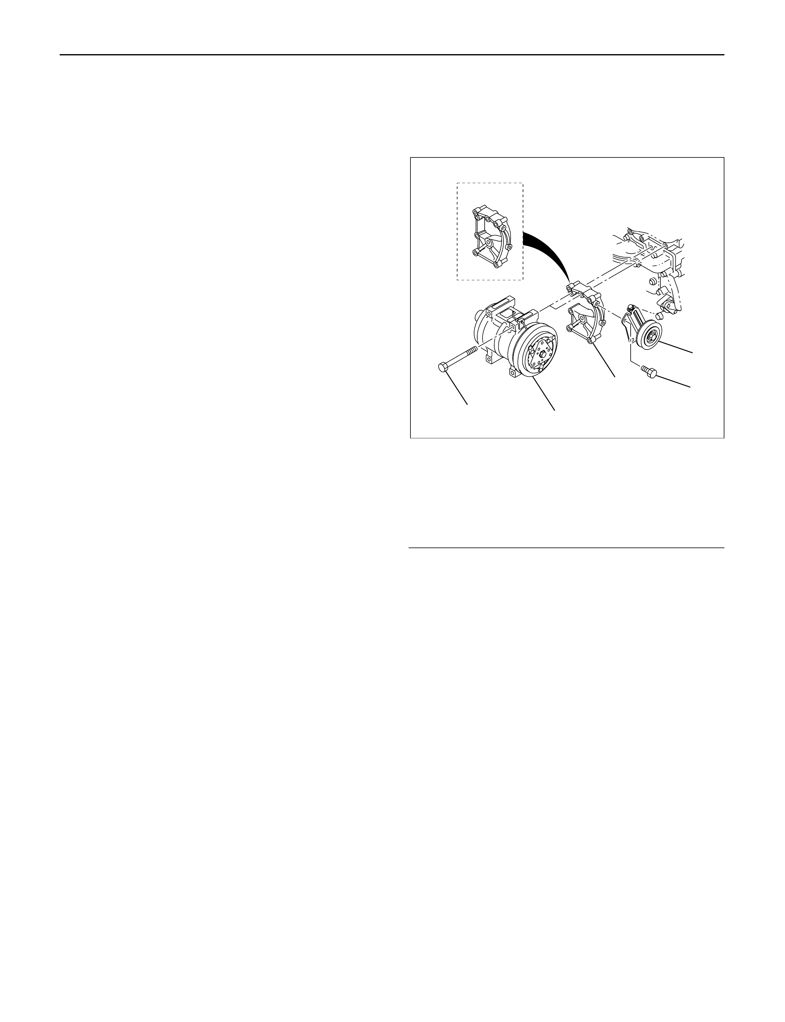
10.A/C Compressor Assembly
1)Tighten temporarily the fixing bolts (upper and
front lower sides of compressor.)
2)Tighten fixing bolt (rear under side of
compressor) to the specified torque.
3)Tighten fixing bolts (front upper and lower sides
of compressor) to the specified torque.
Torque: 40 N·m (4.1 kg·m/30 lb·ft)
Legend
(1)Tensioner
(2)Bolt
(3)Bracket
(4)A/C compressor
(5)Bolt
11.A.C Generator Harness
12.Engine Ground Cable
1)Tighten ground cable to A/C compressor
bracket.
13.Air Cleaner cover & Duct
14.Intercooler Assembly
1)Refer to “Intercooler” in this manual.
15. Radiator Assembly
1) Install rubber cushion in under left and right part
of radiator and position radiator.
2) Fix radiator with bracket.
16. Cooling Fan Assembly
1) Install cooling fan assembly and tighten fixing
bolts to the specified torque.
Torque: 8 N·m (0.8 kg·m/69 lb in)
17. Fan Shroud
18. Radiator Hose
1) Connect upper and lower hose to engine side.
2) Pour coolant into radiator.
19. Install battery.
20. Connect window washer hose and install engine
hood.
1
2
3
4
5
MY2003 Euro-3
F06R200005
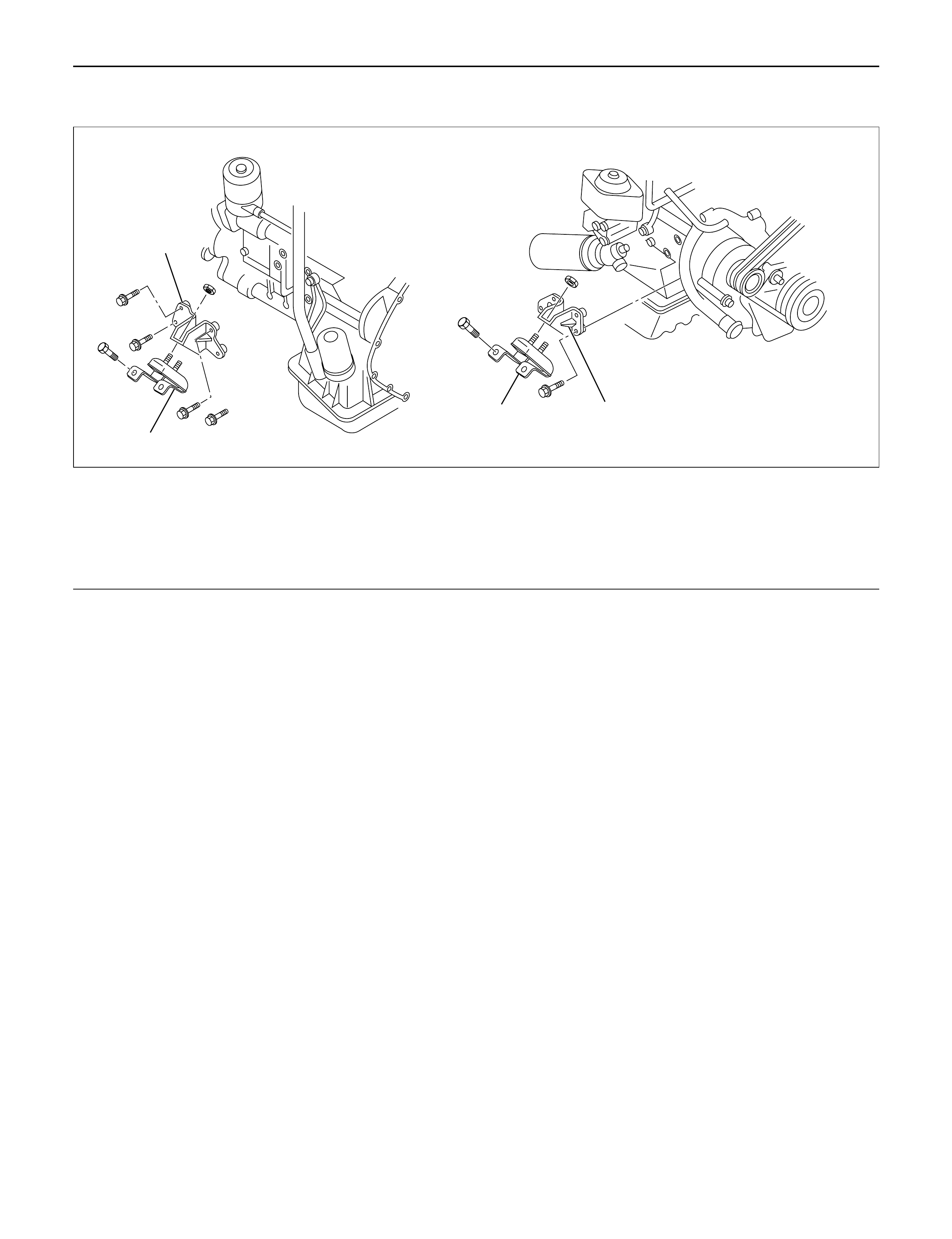
ENGINE MOUNT (RH)
REMOVAL
1. Disconnect battery ground cable
2. Hang the engine assembly.
3. Rubber engine mount.
1) Remove bolts from chassis frame bracket.
2) Remove nuts from rubber engine mount and
engine mounting bracket.
4. Remove bolt which is fixed between engine and
mounting bracket then remove the engine mounting
bracket.
INSTALLATION
•Tighten the fixing bolts to the specified torque.
1. Engine mounting bracket to cylinder block.
Torque : 40 N·m (4.1 kg·m/30 lb ft) (for M10)
127 N·m (13.0 kg·m/94 lb ft) (for M14)
2. Rubber engine mount to chassis frame and engine
mounting bracket.
Torque :40 N·m (4.1 kg·m/30 lb ft)
4
3
1
2
022RW018
Legend
(1) Rubber Engine Mount (LH)
(2) Engine Mounting Bracket (LH)
(3) Rubber Engine Mount (RH)
(4) Engine Mounting Bracket (RH)
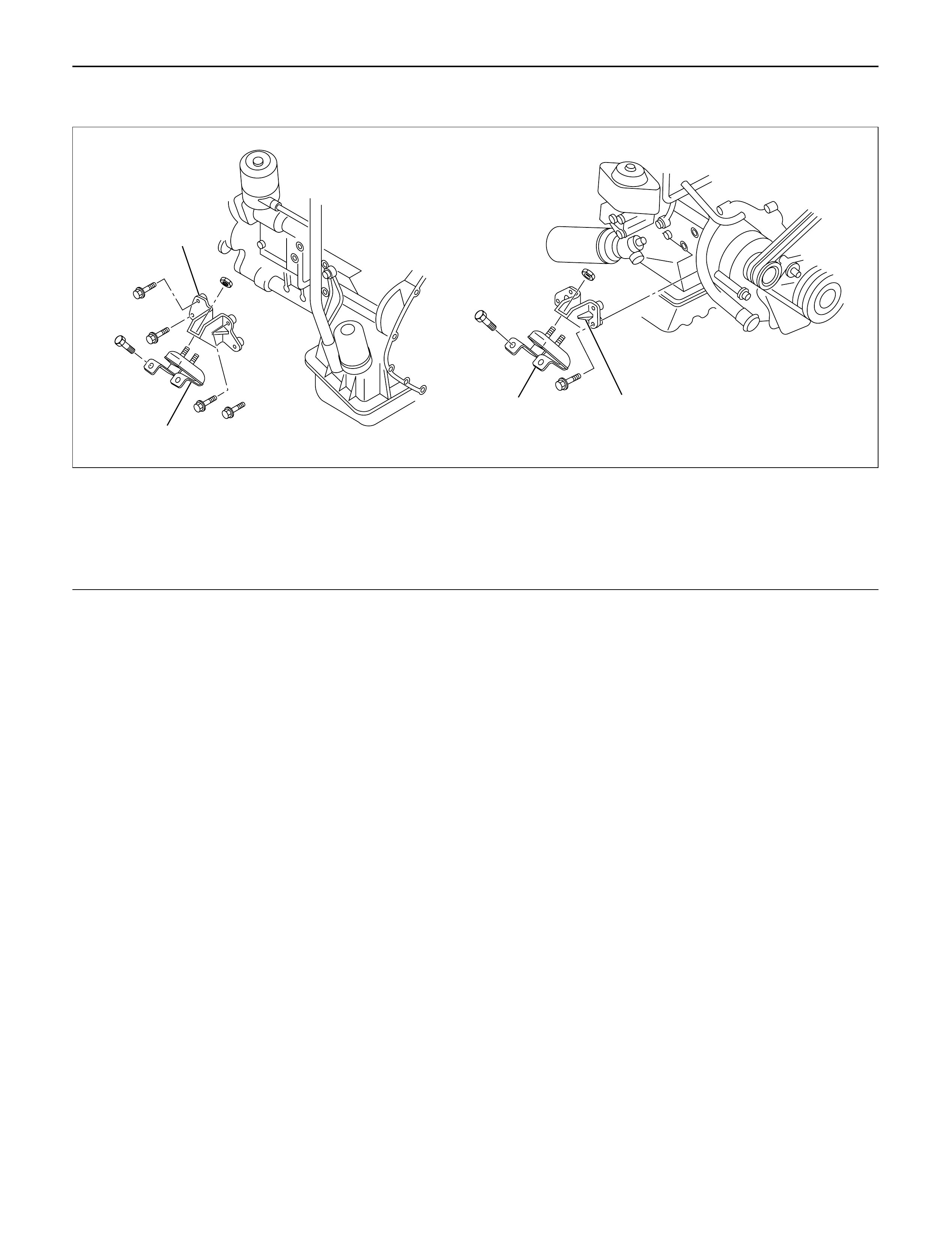
ENGINE MOUNT (LH)
REMOVAL
1. Disconnect battery ground cable
2. Hang the engine assembly.
3. Rubber engine mount.
1) Remove bolts from chassis frame bracket.
2) Remove nuts from rubber engine mount and
engine mounting bracket.
4. Remove bolt which is fixed between engine and
mounting bracket then remove the engine mounting
bracket.
INSTALLATION
•Tighten the fixing bolts to the specified torque.
1. Engine mounting bracket to cylinder block.
Torque : 40 N·m (4.1 kg·m/30 lb ft) (for M10)
127 N·m (13.0 kg·m/94 lb ft) (for M14)
2. Rubber engine mount to chassis frame and engine
mounting bracket.
Torque :40 N·m (4.1 kg·m/30 lb ft)
4
3
1
2
022RW018
Legend
(1) Rubber Engine Mount (LH)
(2) Engine Mounting Bracket (LH)
(3) Rubber Engine Mount (RH)
(4) Engine Mounting Bracket (RH)
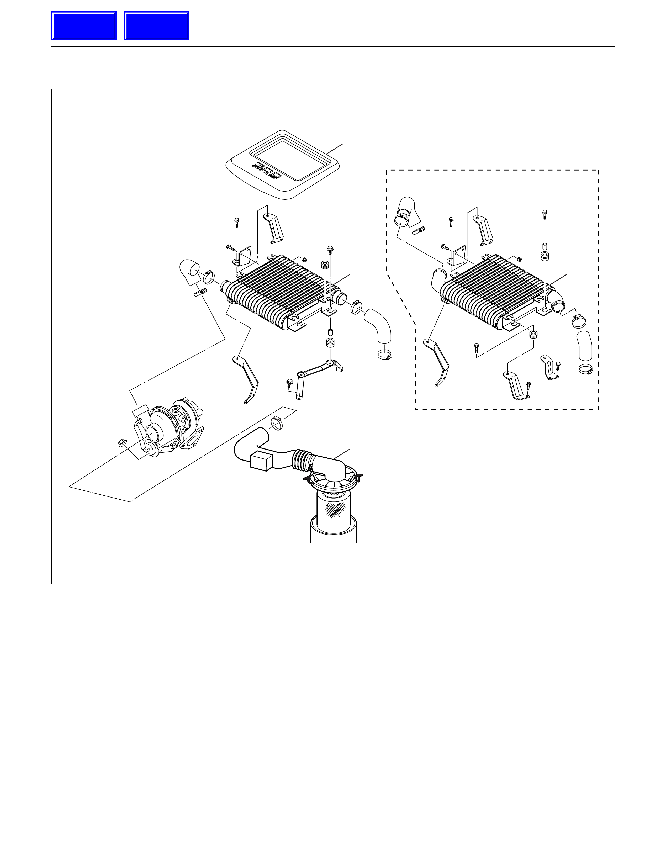
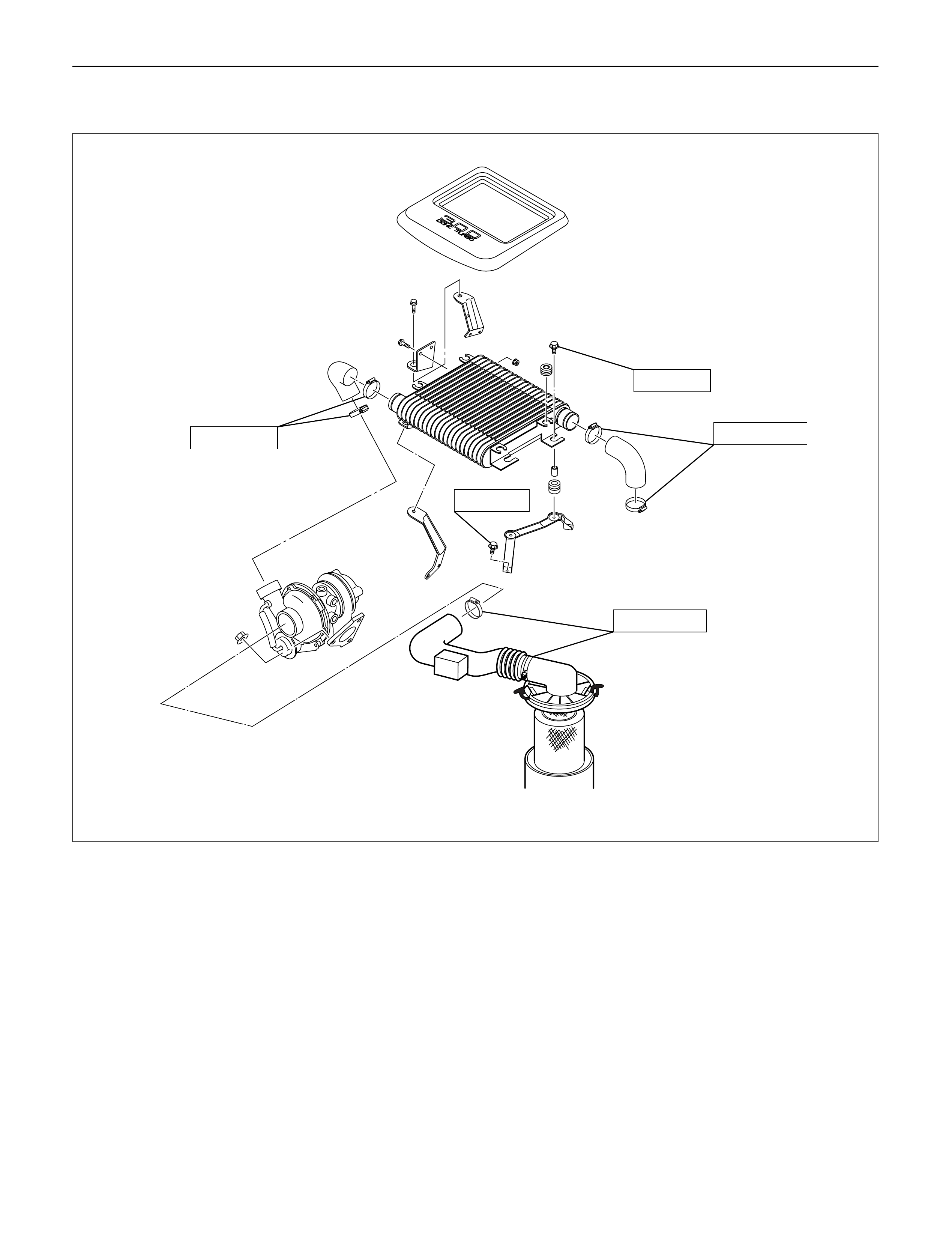
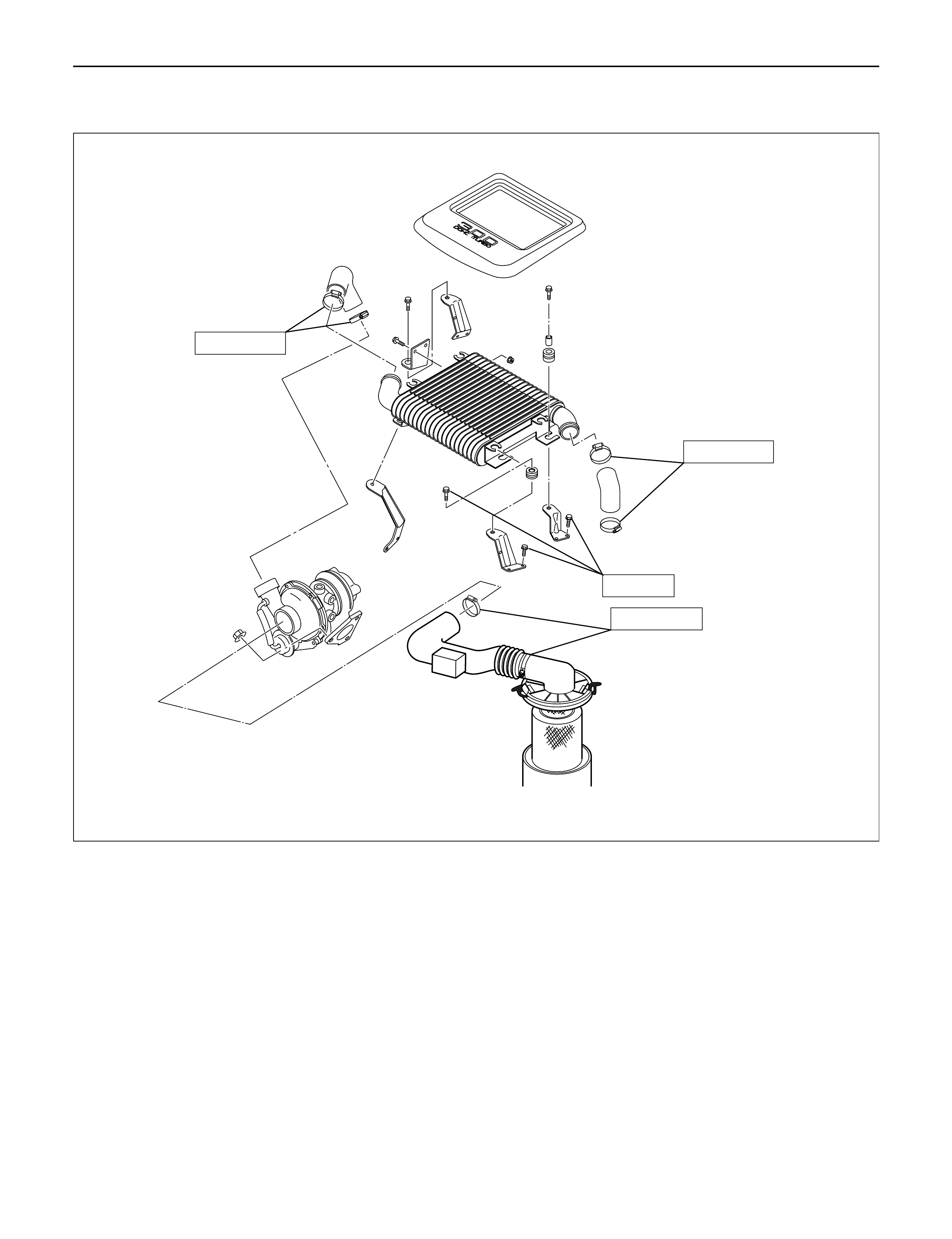
INTERCOOLER
REMOVAL
1. Disconnect the battery ground cable.
2. Remove air cleaner cover and air duct.
3. Remove intercooler cover.
4. Remove intercooler assembly.
1) Remove rubber hose from between intercooler
outlet and intake manifold inlet.
2) Remove rubber hose from between
turbocharger outlet and intercooler inlet.
3) Remove intercooler assembly fixing bolts from
the bracket, remove intercooler assembly.
INSTALLATION
1. Intercooler assembly
1) Connect outlet hose to intake manifold.
Torque : 4 N·m (0.4 kg·m/35 lb in)
2) Connect inlet hose from turbocharger to
intercooler.
Torque : 4 N·m (0.4 kg·m/35 lb in)
3) Install intercooler and tighten fixing bolts to the
specified torque.
Torque : 20 N·m (2.0 kg·m/14 lb ft)
2. Install intercooler cover.
3. Install air cleaner cover and air duct.
4. Connect the battery ground cable.
MY2003 Euro-3
2
3 3
1
135R200003
Legend
(1) Air Cleaner Cover & Air Duct (2) Intercooler Cover
(3) Intercooler Assembly
Techline
Techline
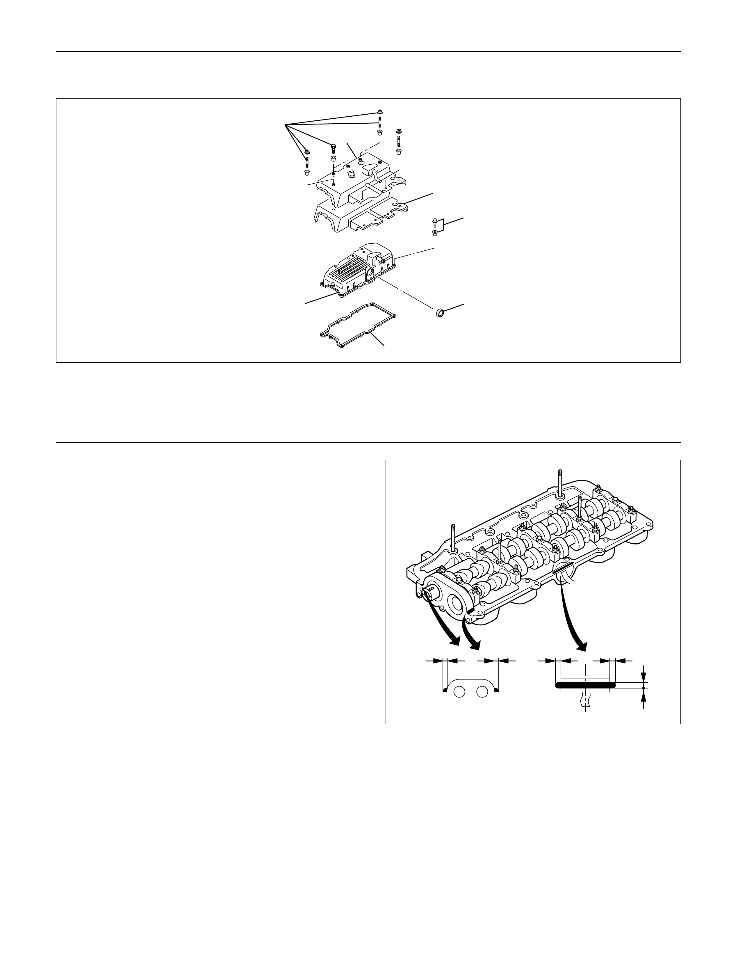
CYLINDER HEAD COVER
REMOVAL
1.Disconnect battery ground cable.
2.Remove clip, remove air cleaner cover and air duct.
3.Remove intercooler assembly.
Refer to “Intercooler” in this manual.
4. Remove PCV hose.
5. Remove bolts which fix noise insulator cover then
remove noise insulator cover and insulator.
6. Remove high pressure oil pipe at cylinder head
side.
Take care when removing the injector oil pipe,
because sometimes, during removal, your hand
can be injured by the remaining high pressure oil.
INSTALLATION
1. Cylinder head cover.
1) Install the cylinder head cover gasket to cylinder
head cover.
2) The gasket must be set perfectly with no loose
areas.
3) Apply liquid gasket (TB1207B or equivalent) to
the rubber seal of the camshaft end, injector
harness gasket area and No. 1 camshaft
bracket.
4) Tighten cylinder head cover fixing bolts to the
specified torque.
Torque : 9 N·m (0.9 kg·m/78 lb in)
2. Fill with about 300 cc of engine oil from the high
pressure oil pipe installation port of the oil rail using
an oil rail filler. If assembled without filling the oil rail
with oil, the time for starting the engine will be
longer.
3. Install the high pressure oil pipe immediately and
tighten the sleeve nut to the specified torque.
Torque : 78 N·m (8.0 kg·m/58 lb ft)
1
7
2
3
4
5
6
010R200006
Legend
(1) Noise Insulator Cover
(2) Insulator
(3) Bolt
(4) Oil Seal
(5) Gasket
(6) Cylinder Head Cover
(7) Bolt
3~52~32~3 3~5
3~51~2
012RW119

NOTE:Do not scratch the oil seal on the cylinder head
during installation of the high pressure oil pipe.
4.Install the noise insulator and its cover on the
cylinder head cover.
NOTE:Do not catch the injector harness with the noise
insulator cover.
5.Connect the PCV hose.
6.Install the intercooler assembly.
Refer to “Intercooler” in this manual.
7. Install air cleaner cover and air duct.
8. Connect battery ground cable.
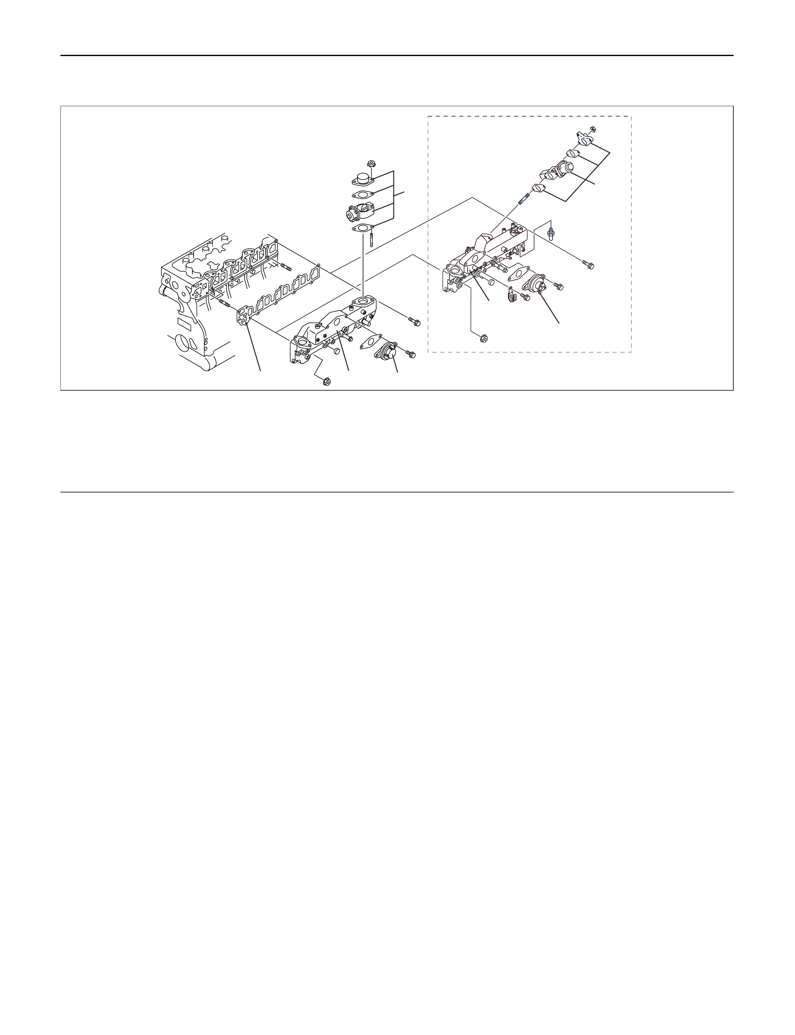
INTAKE MANIFOLD
REMOVAL
1.Drain engine coolant and disconnect water hose
from thermostat hosing.
2.Remove intercooler assembly
Refer to “Intercooler” in this manual.
3.Remove bracket bolt of oil level gauge guide tube.
4.Remove PCV Hose.
5.Remove hoses from EGR, EGR vacuum sensor
and inlet/outlet of heater.
6.Disconnect harness connector form MAPsensor,
EGR vacuum sensor, ETC sensor, water
temperature unit, IATsensor and EVRV.
7.Remove high pressure oil pipe.
8.Remove the two way valve.
9.Remove fuel pipe from between intake manifold
and high pressure oil pump.
10.Remove fixing bolts and nuts on the intake
manifold, then remove the intake manifold
assembly.
INSTALLATION
1.Install the intake manifold, tighten bolts and nuts to
the specified torque.
Torque : 20 N·m (2.0 kg·m/14 lb ft) for bolt and nut
2.Install the fuel pipe and tighten to the specified
torque.
Torque :
M16 bolt (apply engine oil) 4 N·m (0.4 kg·m/35
lb in)
Cap nut (M10) 13N·m (1.3 kg·m/113 lb in)
Fuel pipe (M10 apply engine oil) 14 N·m (1.4
kg·m/122 lb in)
3.Install two way valve.
Torque : 20 N·m (2.0 kg·m/14 lb ft)
4.Fill with about 300 cc of engine oil from the high
pressure oil pipe installation port of the oil rail using
an oil filler. If assembled without filling the oil rail
with oil, the time for starting the engine will be
longer.
5.Install the high pressure oil pipe immediately and
tighten the sleeve nut to the specified torque.
Torque : 78 N·m (8.0 kg·m/58 lb ft)
6.Reconnect harness connector to MAPsensor, EGR
vacuum sensor, ETCsensor, Water temperature
unit, IATsensor and EVRV.
7.Connect the hoses to EGR valve, EGR vacuum
sensor, and water inlet/outlet pipe for heater.
8.Connect PCV hose.
9.Install the oil level gauge guide tube and tighten
bracket bolt.
10.Install the intercooler assembly.
Refer to “Intercooler” in this manual.
11. Connect the hose to the thermostat housing and fill
with engine coolant.
MY2003 Euro-3
2
1
3
3
14
2
025R200005
Legend
(1) Intake Manifold
(2) Throttle Valve Assembly
(3) EGR Valve
(4) Gasket
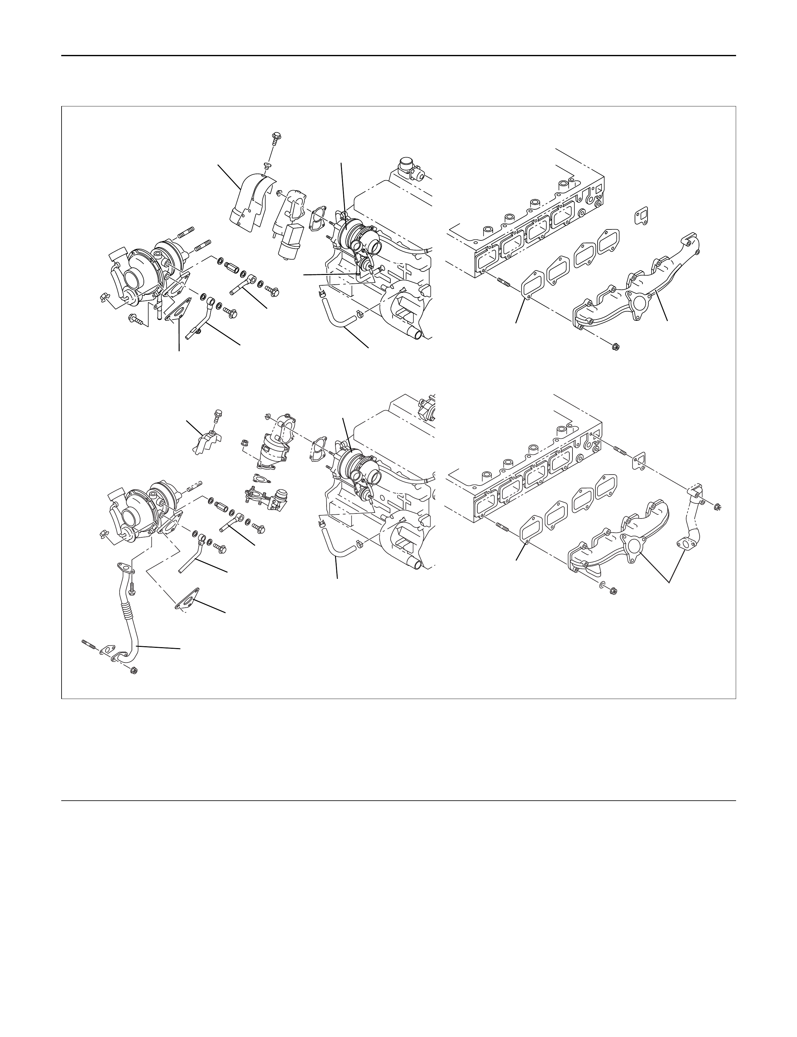
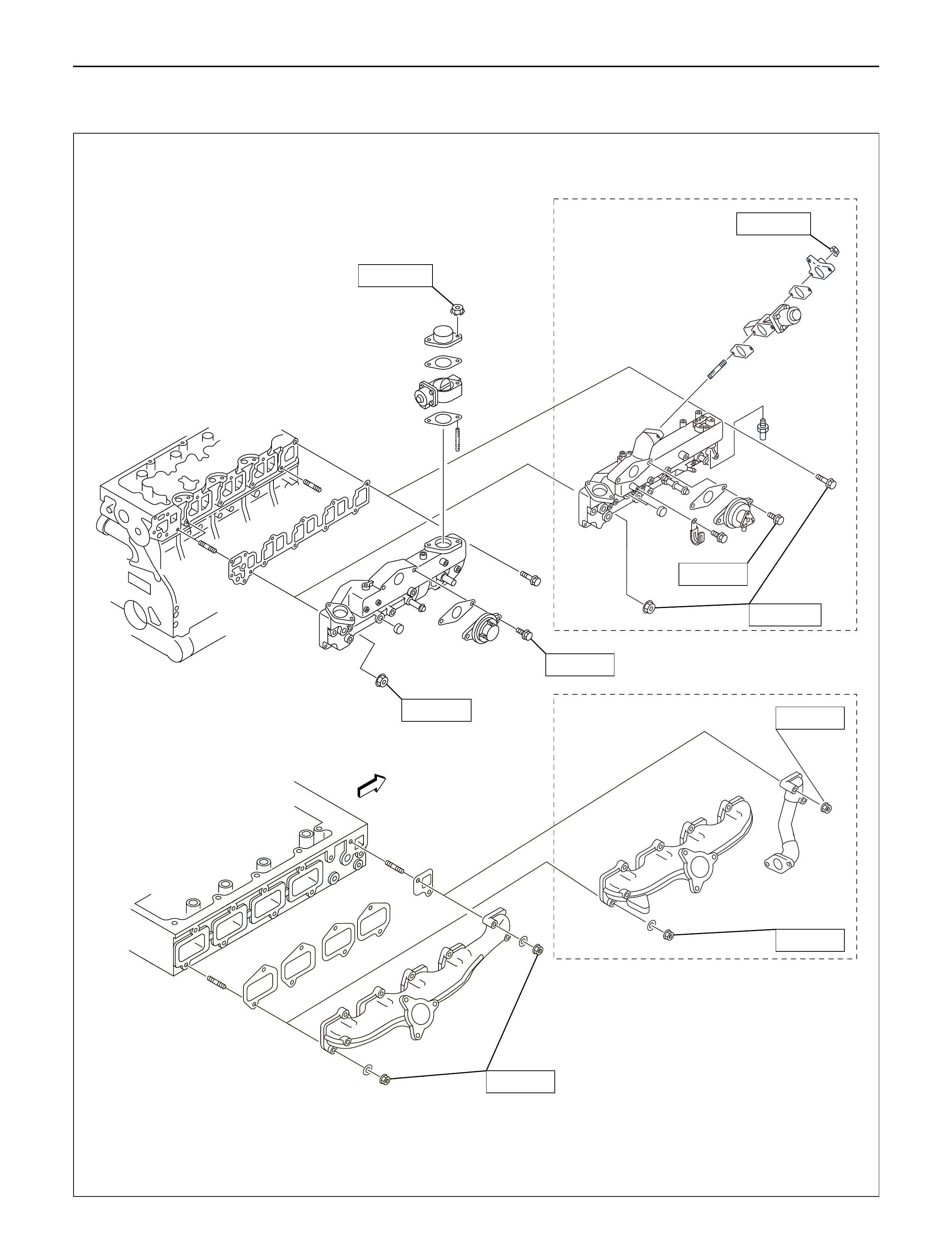
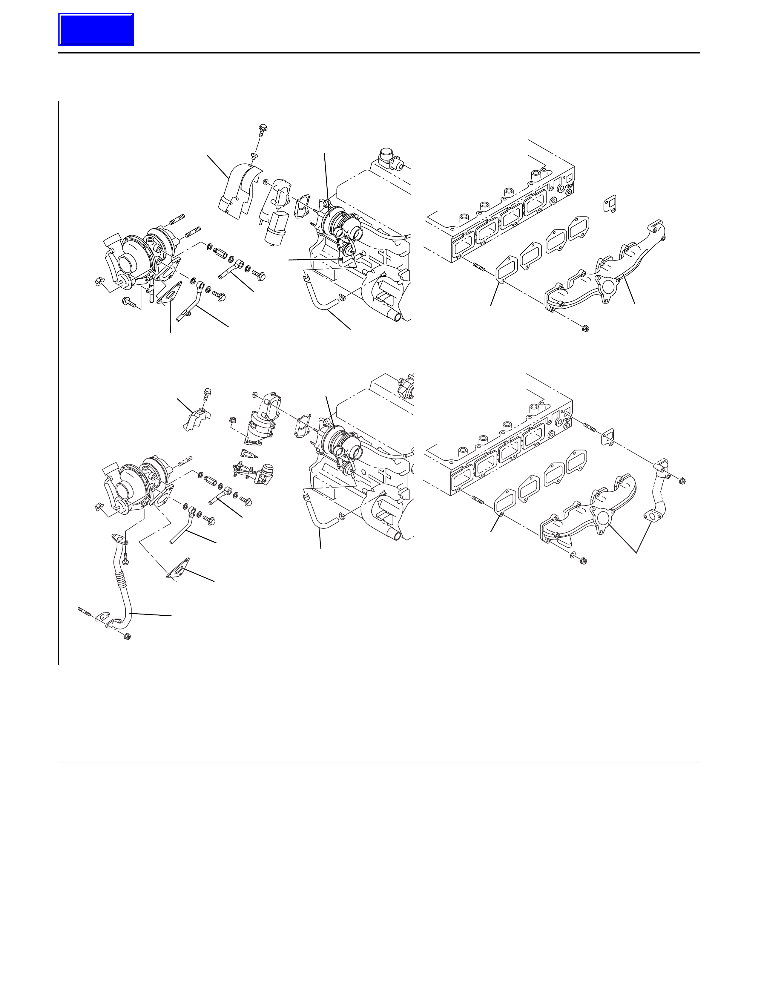
EXHAUST MANIFOLD
9
5
9
8
MY2003 Euro-3
8
7
5
63
21
4
7
4
2
1
3
6
025R200004
Legend
(1) Exhaust Manifold
(2) Gasket
(3) T urbocharger Assembly
(4) Water Hose
(5) Water Hose
(6) Heat Protector
(7) Oil Pipe
(8) Oil Pipe
(9) Gasket
REMOVAL
1. Remove the hose from both turbocharger outlet and
intake manifold inlet side, then remove intercooler
assembly.
2. Loosen belt tensioner, remove A/C compressor
assembly.
3. Remove heat protector from turbocharger.
4. Remove water hoses and oil pipes from
turbocharger.
5. Remove turbocharger assembly from exhaust
manifold.
6. Remove exhaust manifold fixing nuts, then remove
exhaust manifold.

INSTALLATION
1. Install gasket on the exhaust manifold and tighten
to the specified torque.
Torque : 30 N·m (3.1 kg·m/22 lb ft)
2. Install turbocharger on the exhaust manifold.
Torque : 27 N·m (2.8 kg·m/20 lb ft)
3. Install water hoses and oil pipes.
4. Install heat protector to turbocharger.
Torque : 9 N·m (0.9 kg·m/78 lb in)
5. Install A/C compressor assembly and readjust belt
tensioner.
6. Install the intercooler assembly in the normal
position.
Connect both hoses to turbocharger and intake
manifold.
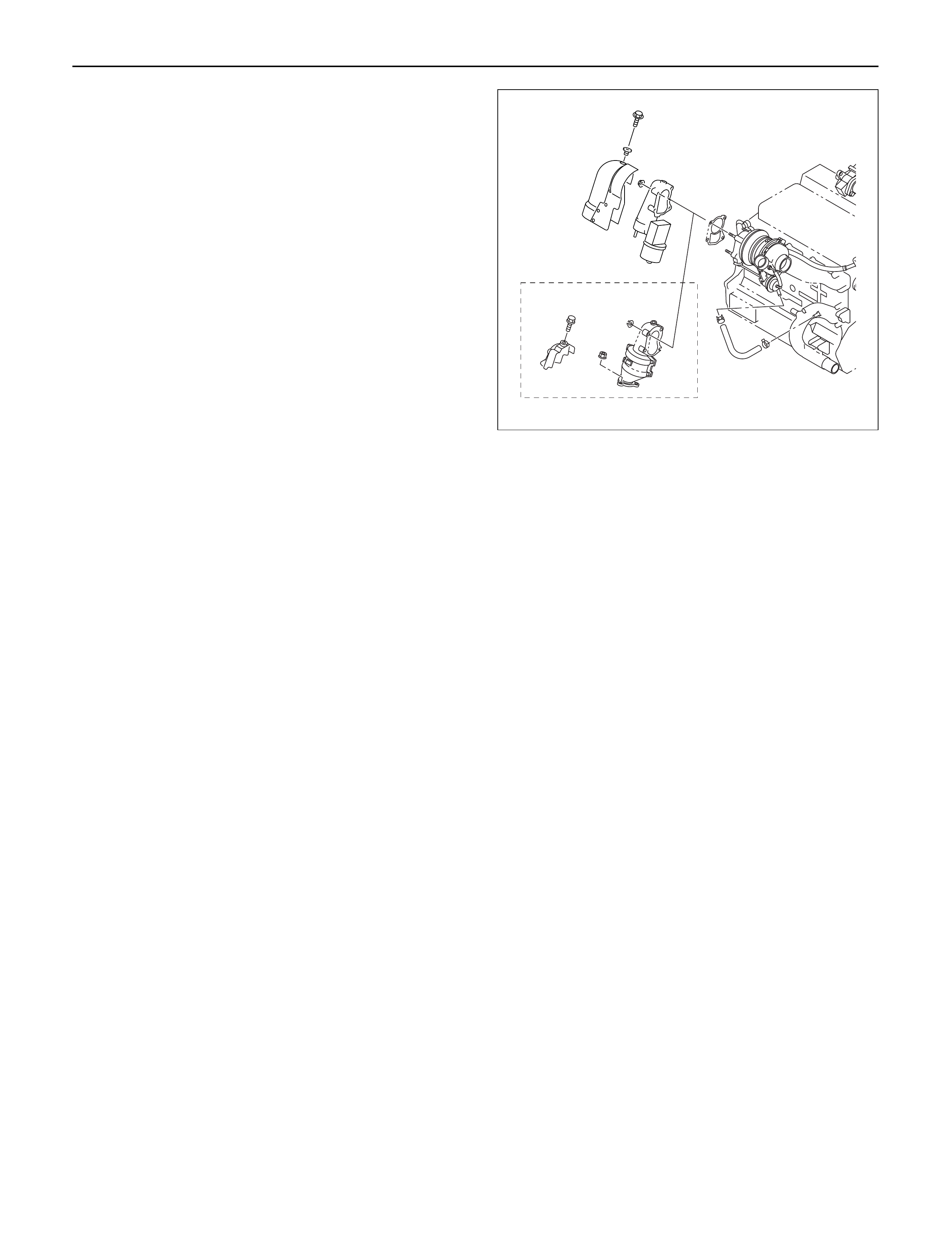
REMOVAL
1.Remove battery.
2.Drain engine coolant.
3.Remove air cleaner cover with air duct.
4.Remove intercooler assembly.
Refer to “Intercooler” in this manual.
5. Remove water pipe for turbocharger inlet.
6. Remove oil pipe for turbocharger.
1) Remove eye bolt from turbocharger.
2) Plug oil port on the turbocharger to prevent entry
of foreign materials.
7. Remove oil drain pipe from turbocharger.
8. Remove water outlet pipe.
9. Remove heat protector.
10. Remove exhaust adaptor.
11. Remove turbocharger assembly from exhaust
manifold.
MY2003 Euro-3
025R200006
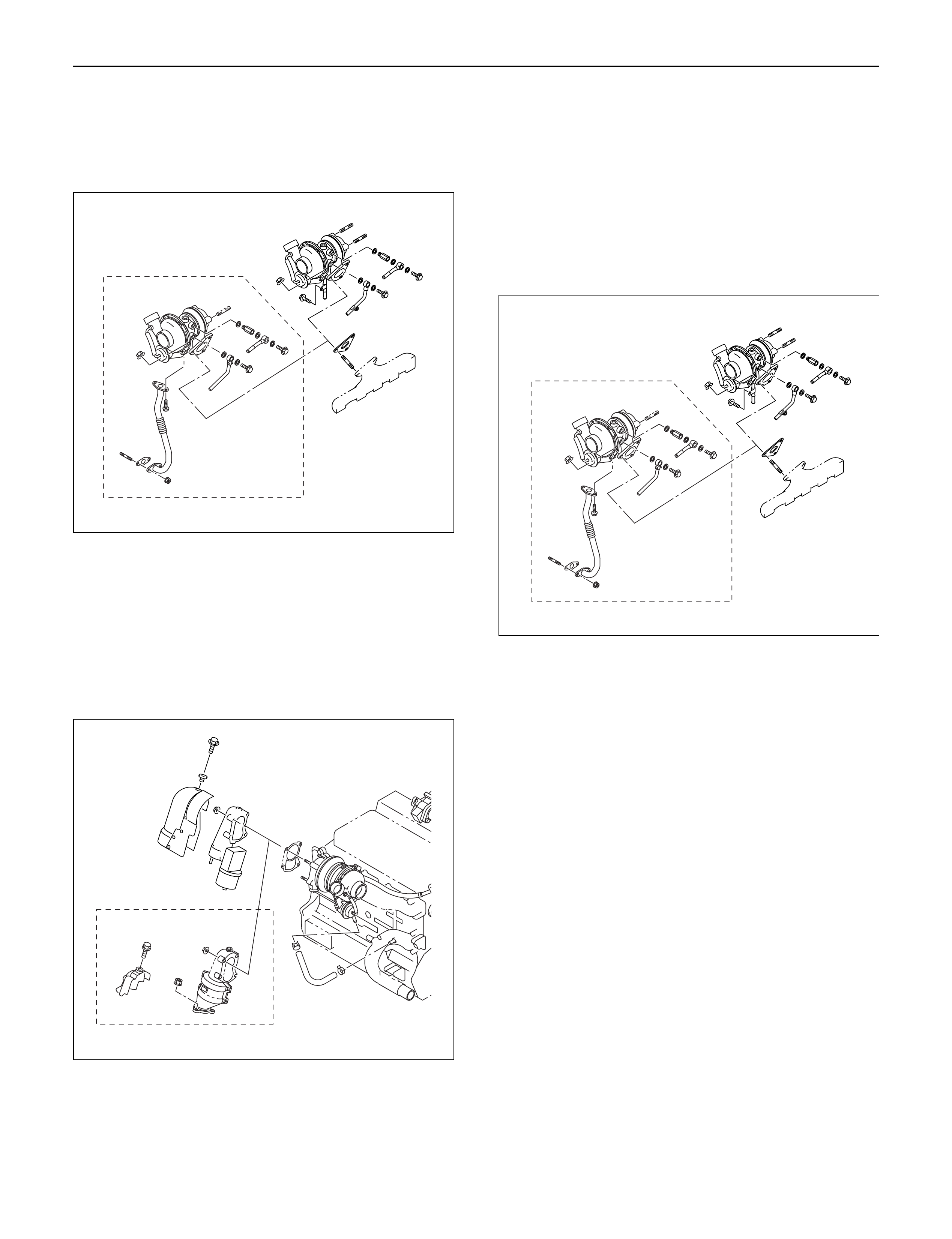
INSTALLATION
1.Install turbocharger assembly to exhaust manifold,
tighten to the specified torque.
Torque : 27 N·m (2.8 kg·m/20 lb ft)
2.Install exhaust adaptor.
Torque : 27 N·m (2.8 kg·m/20 lb ft)
3.Install heat protector.
4.Install water outlet pipe with gasket.
Torque : 20 N·m (2.0 kg·m/14 lb ft)
5.Install turbocharger oil drain pipe.
Torque : 9 N·m (0.9 kg·m/78 lb in)
6.Install oil supply pipe to turbocharger.
1)Fill with 100 cc engine oil at the turbocharger oil
supply hole before installing the oil pipe.
2)Turn the turbocharger by hand to lubricate
turbocharger shaft.
3)Install oil supply pipe with new gasket to the
turbocharger and tighten oil supply pipe bolts to
the specified torque.
Torque :22 N·m (2.2 kg·m/16 lb ft) for M10
54 N·m (5.5 kg·m/40 lb ft) for M14
7.Install water inlet pipe with new gasket, tighten to
the specified torque.
Torque : 20 N·m (2.0 kg·m/14 lb ft)
8.Install intercooler assembly.
Refer to “Intercooler” in this manual.
9. Install air cleaner cover with air duct, connect both
side hoses.
10. Fill with engine coolant.
11. Install the battery and connect battery cables.
MY2003 Euro-3
025R200007
MY2003 Euro-3
025R200007
MY2003 Euro-3
025R200006

CYLINDER HEAD
3
41
2
012RW096
Legend
(1)Glow Plug
(2)Plate
(3)Cylinder Head Bolt
(4)Cylinder Head
NOTE:
•During disassembly, be sure that the valve train
components are kept together and identified so that
they can be re-installed in their original locations.
•Before removing the cylinder head from the engine
and before disassembling the valve mechanism, do
a compression test and note the results.
DISASSEMBLY
1.Injector Assy
2.Glow Plug and Glow Plug Connector
3.Cylinder Head Assembly
•Refer to “Cylinder Head Gasket”
CLEAN
•Cylinder head
Carefully remove all varnish, soot and carbon on
the bare metal. Do not use a motorized wire brush
on any gasket sealing surface.
INSPECTION AND REPAIR
Make the necessary adjustments, repairs, and part
replacements if excessive wear or damage is
discovered during inspection.
1. Cylinder head gasket and mating surfaces for
leaks, corrosion and blow-by. If the gasket has
failed, determine the cause;
– Improper installation
– Loosen or warped cylinder head
– Insufficient torque on head bolts
– Warped cylinder block surface
2.Cylinder head for cracks, especially between valve
seats and in the exhaust ports.
3.Cylinder head deck for corrosion, sand particles in
head and porosity.
CAUTION: Do not attempt to weld the cylinder
head. Replace it.
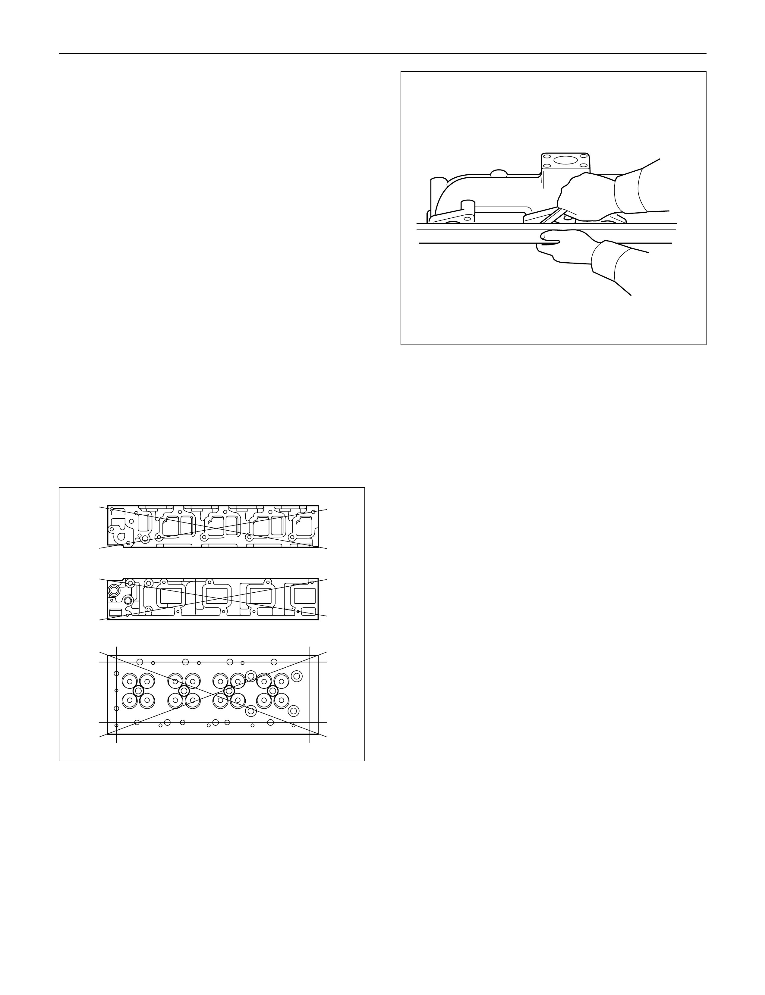
4.Cylinder head lower surface for flatness.
Use a straight edge and a feeler gauge to measure
the cylinder head lower surface warpage.
If the measured values exceed the specified limit,
the cylinder head must be replaced.
Cylinder Head Lower Face Warpage:
Standard: 0.075 mm (0.0029 in) or less
Limit: 0.2 mm (0.0079 in)
Cylinder Head Height:
Standard: 95 mm (3.740 in)
5.Water jacket sealing plugs seating surfaces.
6.Use a straight edge and a feeler gauge to measure
the manifold cylinder head fitting face warpage.
If the measured values exceed the specified limit,
the manifold must be replaced.
Exhaust Manifold Warpage:
Standard: 0.05 mm (0.0020 in) or less
Limit: 0.20 mm (0.0079 in)
CAUTION: Do not attempt to weld the cylinder
head. Replace it.
REASSEMBLY
1.Cylinder Head
•Refer to “Cylinder Head Gasket”.
2. Glow Plug and Glow Plug Connector
•Tighten glow plugs.
Torque: 15 N·m (1.5 kg·m/11 lb ft)
011RW006
012RW053
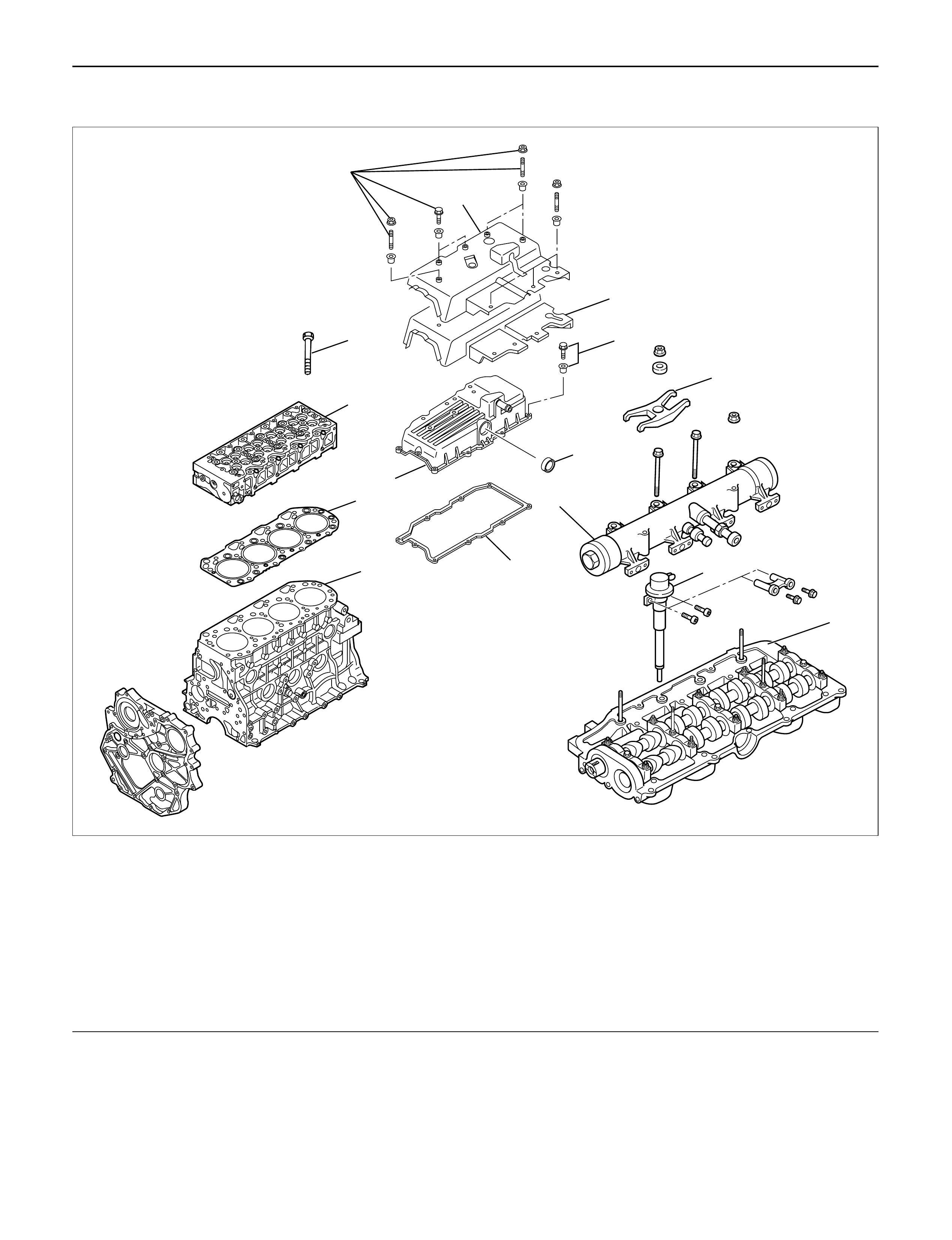
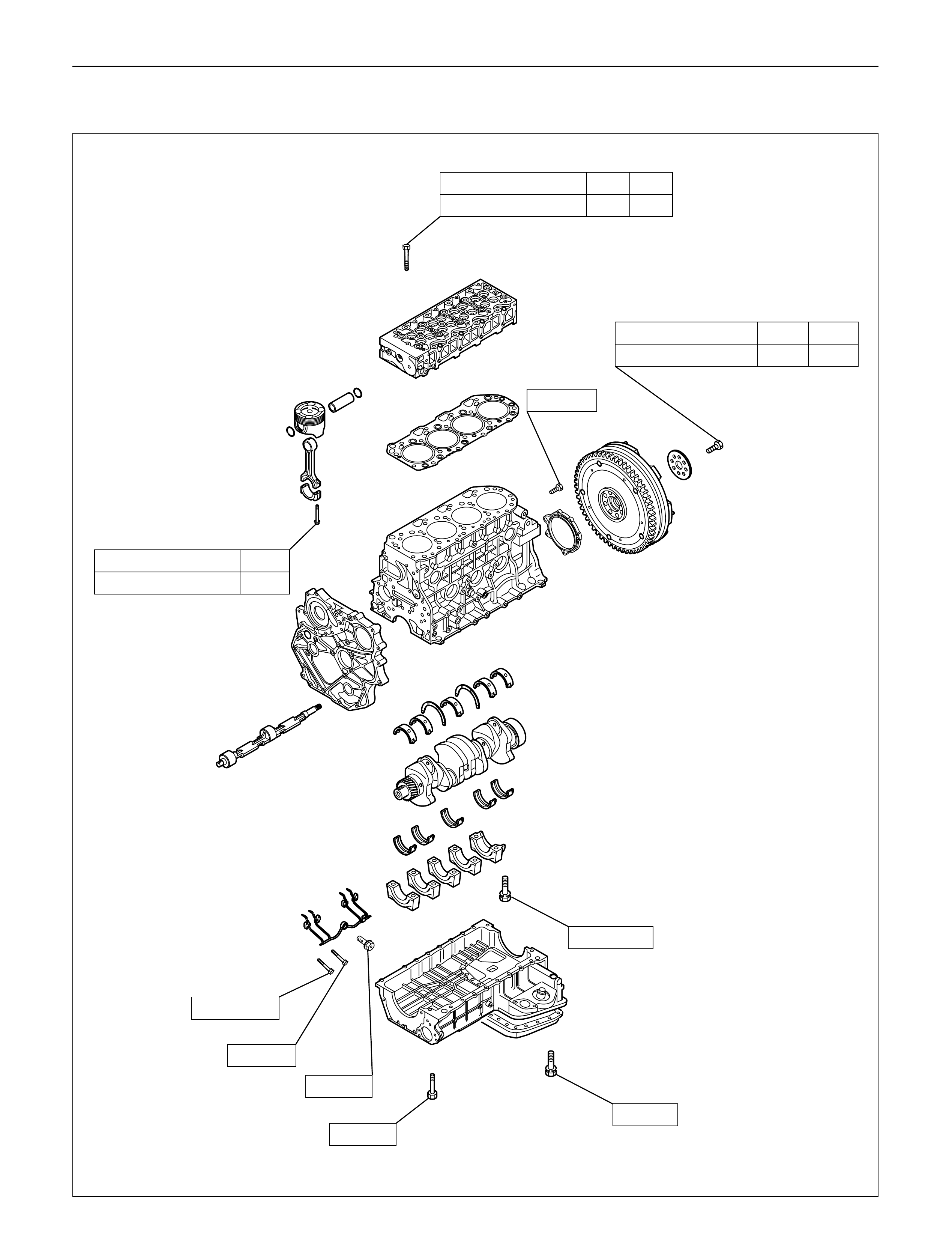
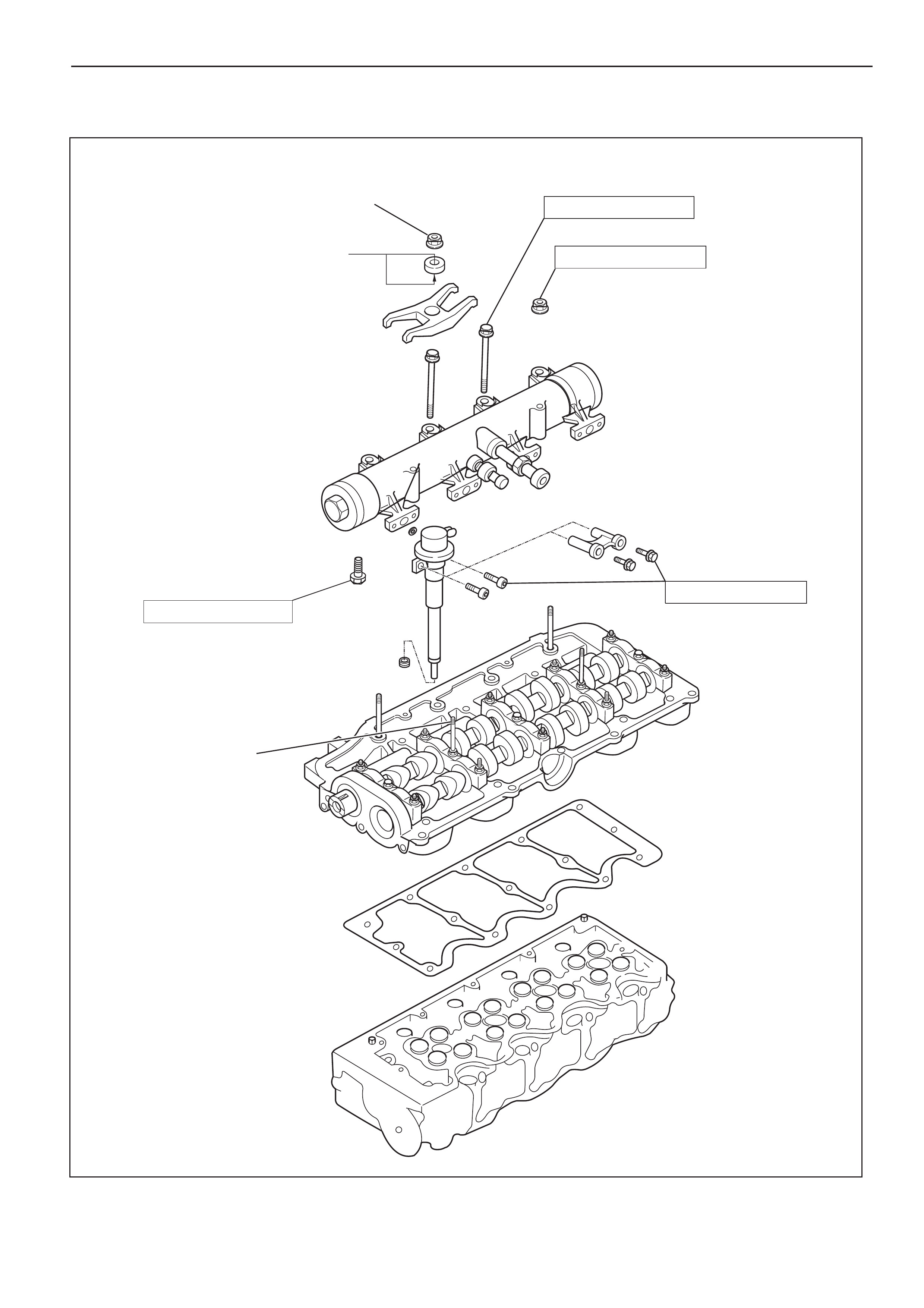
CYLINDER HEAD GASKET
12
13
14
15
8
3
4
5
6
10
11
9
With
spacer type
Without
spacer type
1
7
2
011R200002
Legend
(1) Cylinder Head Noise Insulator Cover
(2) Insulator
(3) Bolt and Gasket
(4) Oil Seal
(5) Gasket
(6) Cylinder Head Cover
(7) Bolt, Stud and Rubber Mounting
(8) Injector Clamp
(9) Oil Rail
(10) Injector Assembly
(11) Camshaft Carrier
(12) Cylinder Head Bolt
(13) Cylinder Head Assembly
(14) Cylinder Head Gasket
(15) Cylinder Block
REMOVAL
1.Disconnect battery ground cable.
2.Drain engine coolant.
3.Remove air cleaner and air duct.
4.Remove intercooler assembly.
Refer to “Intercooler” in this manual.
5. Remove oil level gauge guide assembly.
6. Remove PCV hose.
7. Remove EGR vacuum hose.
8. Disconnect harness connector around the cylinder
head.
9. Remove A/C compressor assembly.
10. Remove A/C compressor bracket.
11. Remove generator assembly and take out fan belt.
12. Remove heat protector and remove valve
assembly.
13. Remove water hose and oil pipe from turbocharger.
14. Remove turbocharger assembly.
15. Remove water hose between thermostat and
radiator.
16. Remove cylinder head noise insulator cover.
NOTE: Do not make damage to the harness.
17. Remove high pressure pipe.
18. Remove timing belt cover.
19. Remove CMP sensor bracket.
20. Remove timing belt tensioner and remove timing
belt.
21. Remove camshaft pulley.
22. Remove front plate.
23. Remove water pipe between cylinder head and
water pump.
24. Remove fuel pipe between fuel pump and intake
manifold.
25. Remove fuel return pipe.
26. Remove intake manifold assembly.
27. Disconnect glow plug wiring and remove glow plug.
28. Remove cylinder head cover.
29. Drain oil from oil rail.
30. Disconnect injector harness connector.
31. Disconnect harness connector from oil pressure
sensor and oil temperature sensor on the oil rail.
32. Disconnect injector harness assembly.
33. Remove injector clamp.
34. Remove injector spacer (If equipped.).
35. Remove injector assembly.
36. Remove oil rail assembly.
37. Remove camshaft carrier.
38. Remove cylinder head assembly.
39. Remove cylinder gasket.
INSTALLATION
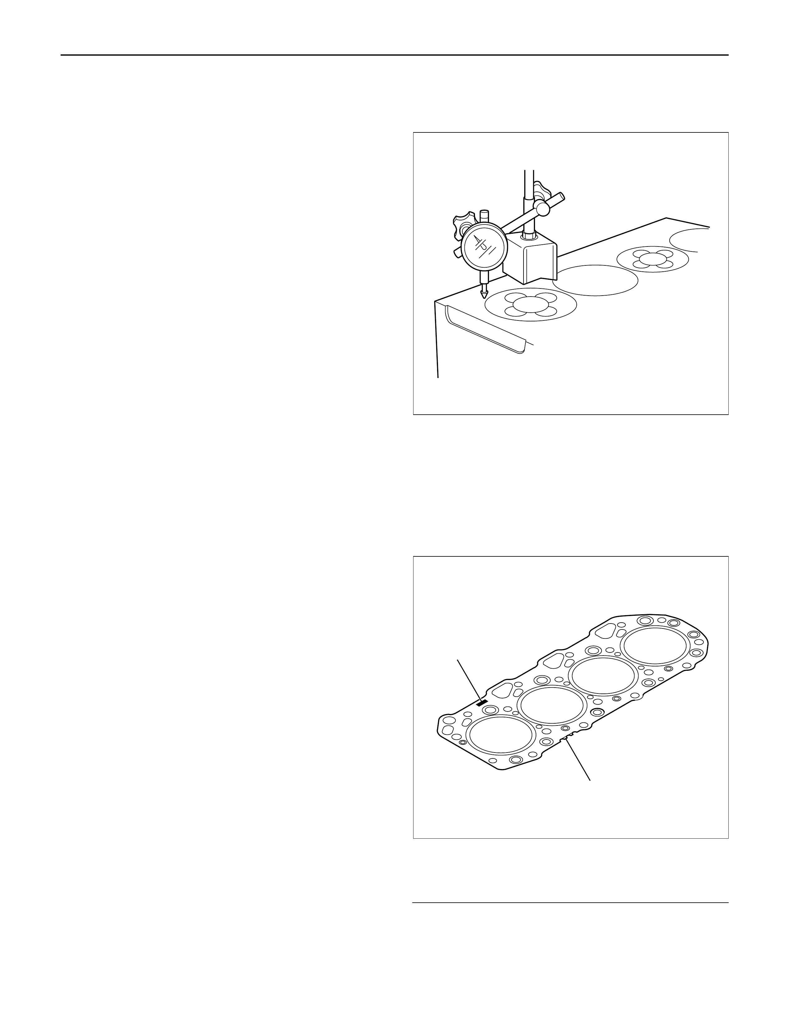
1. Install cylinder head gasket with top mark up.
NOTE: Determine cylinder head gasket grade by
measuring projection of piston head.
2. Selection cylinder head gasket.
1) Measure the piston head projection by dial
gauge.
2) Measure the projection of piston head at the
nearest possible point to the cylinder bore.
3) Obtain the largest measurement from among all
cylinders.
4) Determine cylinder head gasket grade by
maximum value of measuring projection of
piston head.
Legend
(1) Top Mark
(2) Grade Mark
012RW073
2
1
011RW043
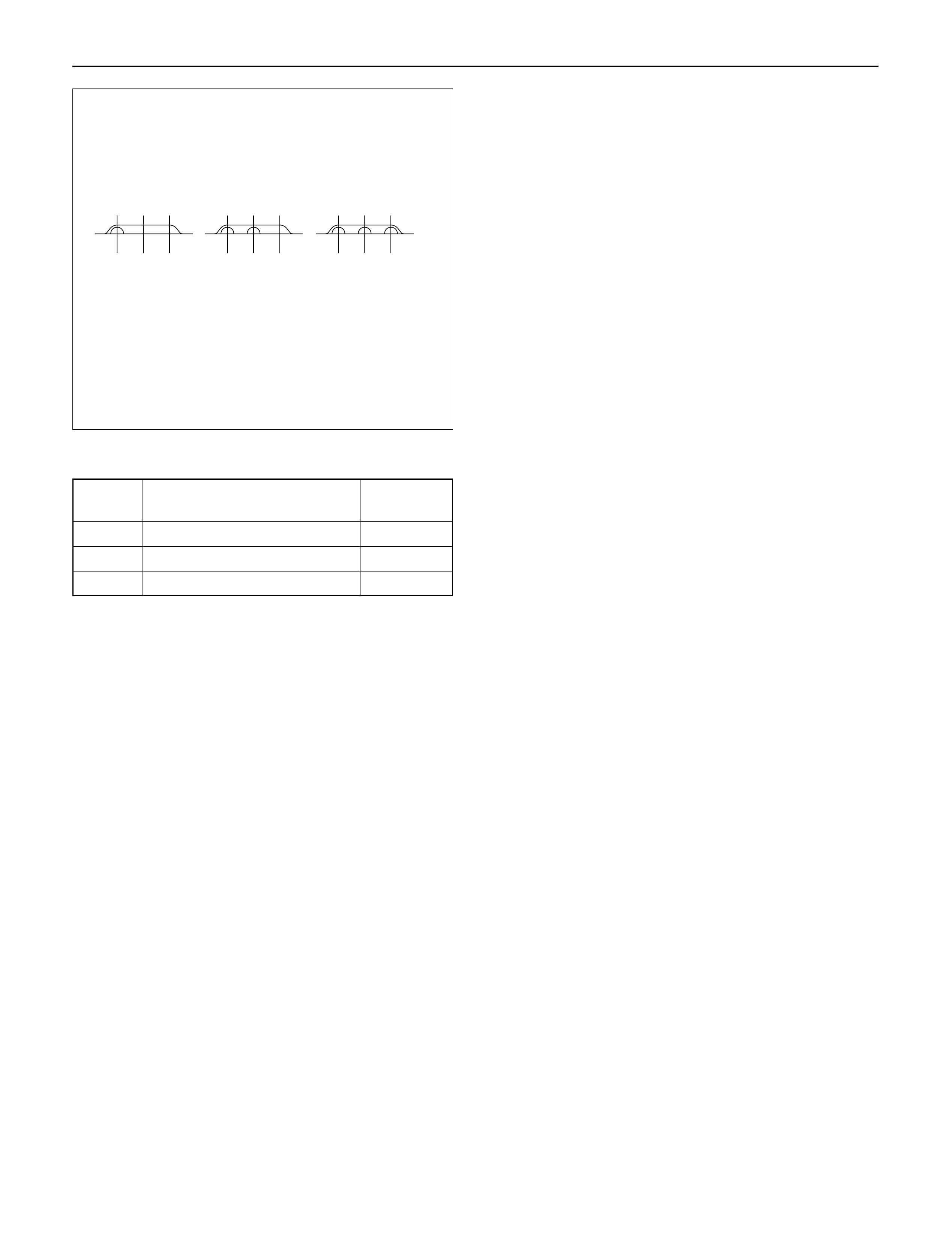
Cylinder head gasket and piston projection mm
CAUTION:
•The projection of each piston should be 0.333
mm or more and less than 0.483 mm.
•Maximum difference in projection between
pistons should be less than 0.1 mm.
•If the piston projection is without standard,
reassemble the engine all over again.
3.Install cylinder head assembly, tighten bolts by
angular tightening method.
Torque:
1st step;49 N·m (5.0 kg·m/36 lb ft)
2nd step;60°
3rd step;60°
CAUTION: The cylinder head bolts cannot be
reused.
4.Install camshaft carrier assembly.
Refer to “Camshaft” in this manual.
5.Install oil rail and injector assembly.
Refer to “Oil rail and injector” in this manual.
6.Install injector harness to connect harness
connector.
Note: Apply liquid gasket (TB 1207B or equivalent) to
the rubber seal of the camshaft end, injector harness
gasket area and No. 1 camshaft bracket. Refer to the
Cylinder head cover.
7.Install cylinder head cover.
Torque: 9 N·m (0.9 kg·m/78 lb in)
8.Install glow plug to tighten specified torque.
Torque: 15 N·m (1.5 kg·m/11 lb ft) and connect
glow plug harness.
9.Install intake manifold.
Torque: 20 N·m (2.0 kg·m/14 lb ft)
10.Install fuel return pipe.
11.Install fuel pipe in between fuel pump and intake
manifold.
12.Install water pipe in between cylinder head and
water pump.
Tighten flange bolt to the specified torque.
Torque: 20 N·m (2.0 kg·m/14 lb ft)
13.Install front plate.
Torque: 20 N·m (2.0 kg·m/14 lb ft)
14.Install camshaft pulley, tighten with angular
tightening method.
1st step40 N·m (4.1 kg·m/30 lb ft)
2nd step60°
NOTE:Apply engine oil to camshaft pulley bolt.
15.Align timing mark oil pump pulley and camshaft
pulley to front plate then put the timing belt and
tighten tensioner bolt.
Torque:20 N·m (2.0 kg·m/14 lb ft) for M8
50 N·m (5.1 kg·m/37 lb ft)
16.Install CMPsensor bracket.
17.Install timing belt cover.
Torque: 9 N·m (0.9 kg·m/78 lb in)
18. Fill with about 300 cc of engine oil from the high
pressure oil pipe installing port of oil rail using an oil
filler.
If assembled without filling the oil rail with oil, the
time for engine start will be longer.
19. Immediately install high pressure oil pipe to tighten
with specified torque.
Torque: 78 N·m (8.0 kg·m/58 lb ft)
20. Install cylinder head noise insulator cover.
Torque: 9 N·m (0.9 kg·m/78 lb in)
Grade A Grade B Grade C
011RW042
Grade Piston projection Gasket
thickness
A more 0.333 to less 0.383 1.35
B more 0.383 to less 0.433 1.40
C more 0.433 to less 0.483 1.45
Legend
(1)Cylinder Head Noise Insulator Cover
(2)Insulator
(3)Bolt
(4)Oil Seal
(5)Gasket
(6)Cylinder Head Cover
(7)Bolt, Stud and Rubber Mounting
21.Install water hose between thermostat and radiator.
22.Install turbocharger assembly to exhaust manifold.
Torque: 27 N·m (2.8 kg·m/20 lb ft)
23.Install water hose and oil pipe for turbocharger.
24.Install exhaust valve assembly and heat protector.
Torque: 57 N·m (5.8 kg·m/42 lb ft) for valve
Torque: 9 N·m (0.9 kg·m/78 lb in) for heat protector
25.Install generator assembly.
Torque: 40 N·m (4.1 kg·m/30 lb ft) for ACG bracket
Torque: 40 N·m (4.1 kg·m/30 lb ft) between ACG and
bracket
Torque: 20 N·m (2.0 kg·m/14 lb ft) between ACG
and adjuster plate
26.Fix the A/C compressor bracket and install A/C
compressor.
Torque: 46 N·m (4.7 kg·m/34 lb ft) for A/C bracket
Torque: 20 N·m (2.0 kg·m/14 lb ft) for belt tensioner
27.Reconnect harness connector around cylinder
head.
28.Connect EGR vacuum hose.
29.Install oil level gauge guide assembly.
Tighten nuts lower portion and tighten bolt.
Torque: 20 N·m (2.0 kg·m/14 lb ft)
30.Install intercooler assembly.
Refer to “Intercooler” in this manual.
31. Install air duct between air cleaner and
turbocharger.
32. Fill engine coolant.
33. Reconnect battery.
MY2003 Euro-3
025R200007
MY2003 Euro-3
025R200006
1
7
2
3
4
5
6
010R200006
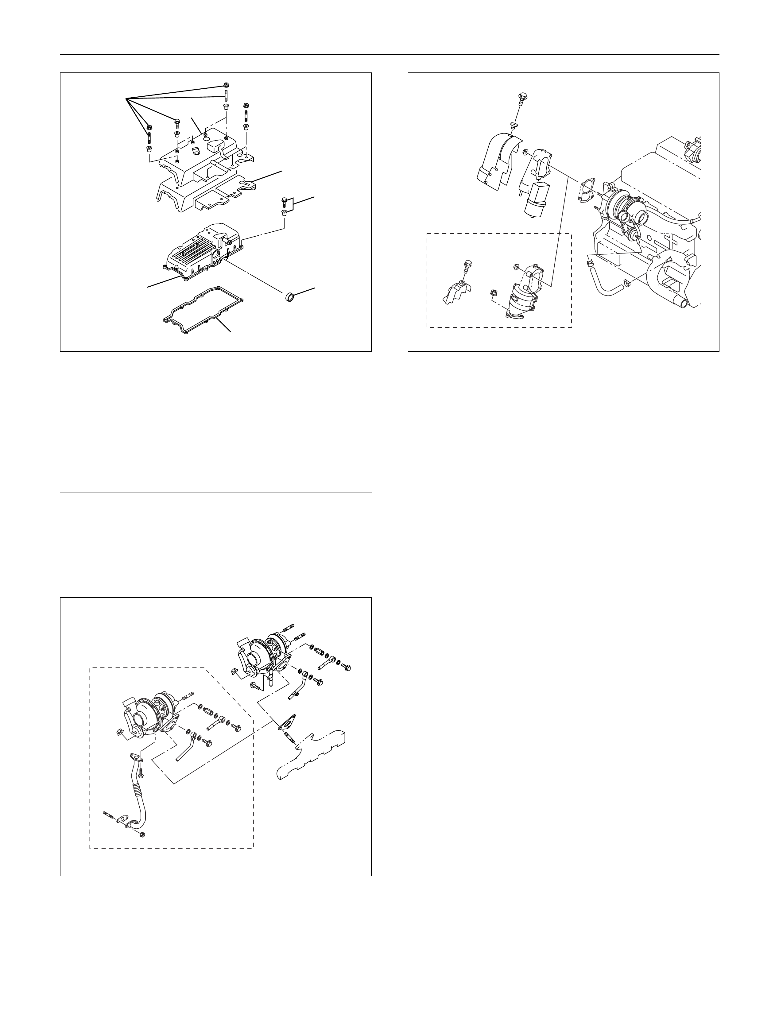
CAMSHAFT
2
1
6
With
spacer type
Without
spacer type
13
14
8
12
11 10 9
3
4
7
5
012R200004
Legend
(1) Nut and Washer
(2) Injector Clamp
(3) Nut
(4) Bolt
(5) Oil Rail Assembly
(6) Spacer (If equipped) and Bolt
(7) Injector Assembly
(8) Camshaft
(9) Camshaft Carrier
(10) Plug
(11) Oil Seal
(12) Camshaft Bracket
(13) Gasket
(14) Gasket
DISASSEMBLY
1. Injector clamp
2. Injector assembly
3. Oil rail assembly
4. Camshaft bracket
5. Camshaft
6. Oil seal
7. Plug
NOTE: Before starting disassembly above, drain oil
from oil rail to prevent oil from entering the cylinder.
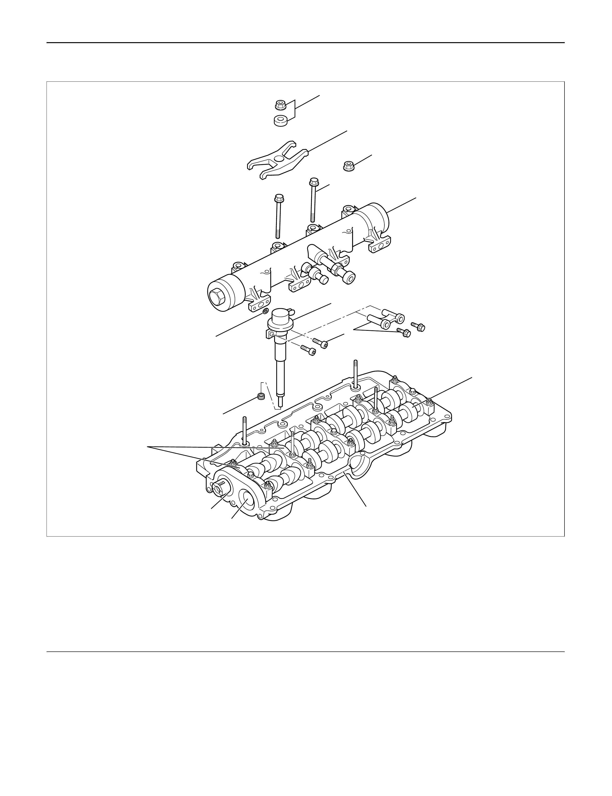
REASSEMBLY
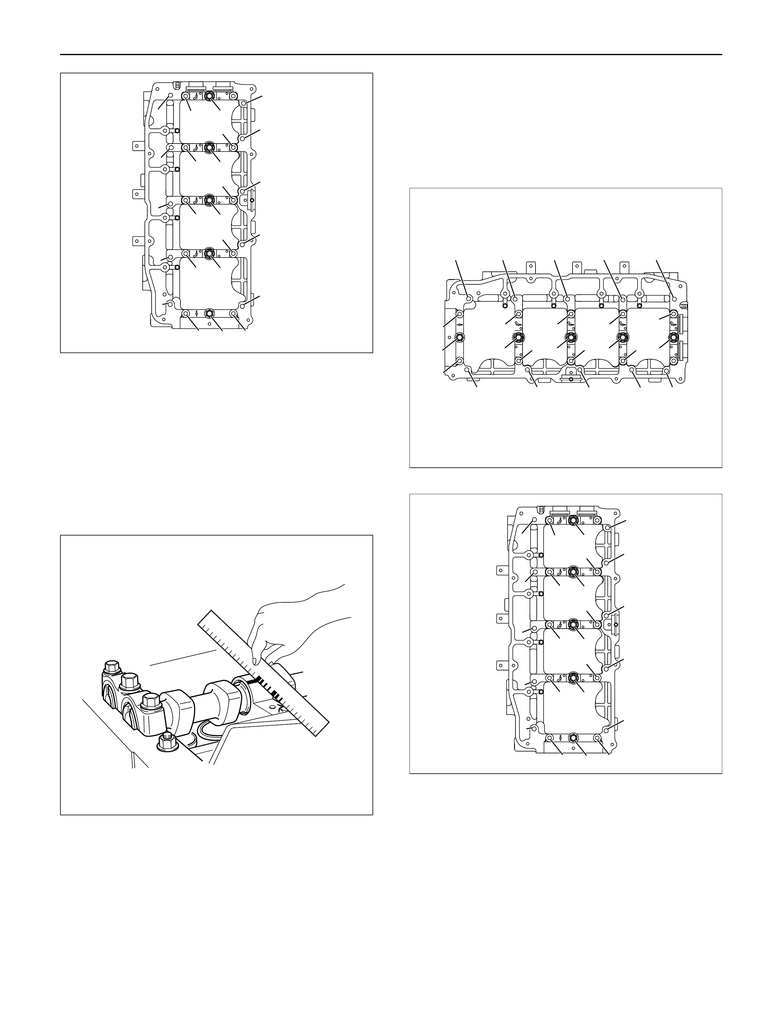
1. Camshaft
1) Before reassembling the camshaft to the
camshaft carrier, align the holes between the
main gear and the sub gear on the intake side of
the camshaft gear with a special tool.
2) Set lock pin to gear holes from sub gear side.
Camshaft Gear Tool: 5-8840-2591-0
Legend
(1) Locking pin
(2) Special tool
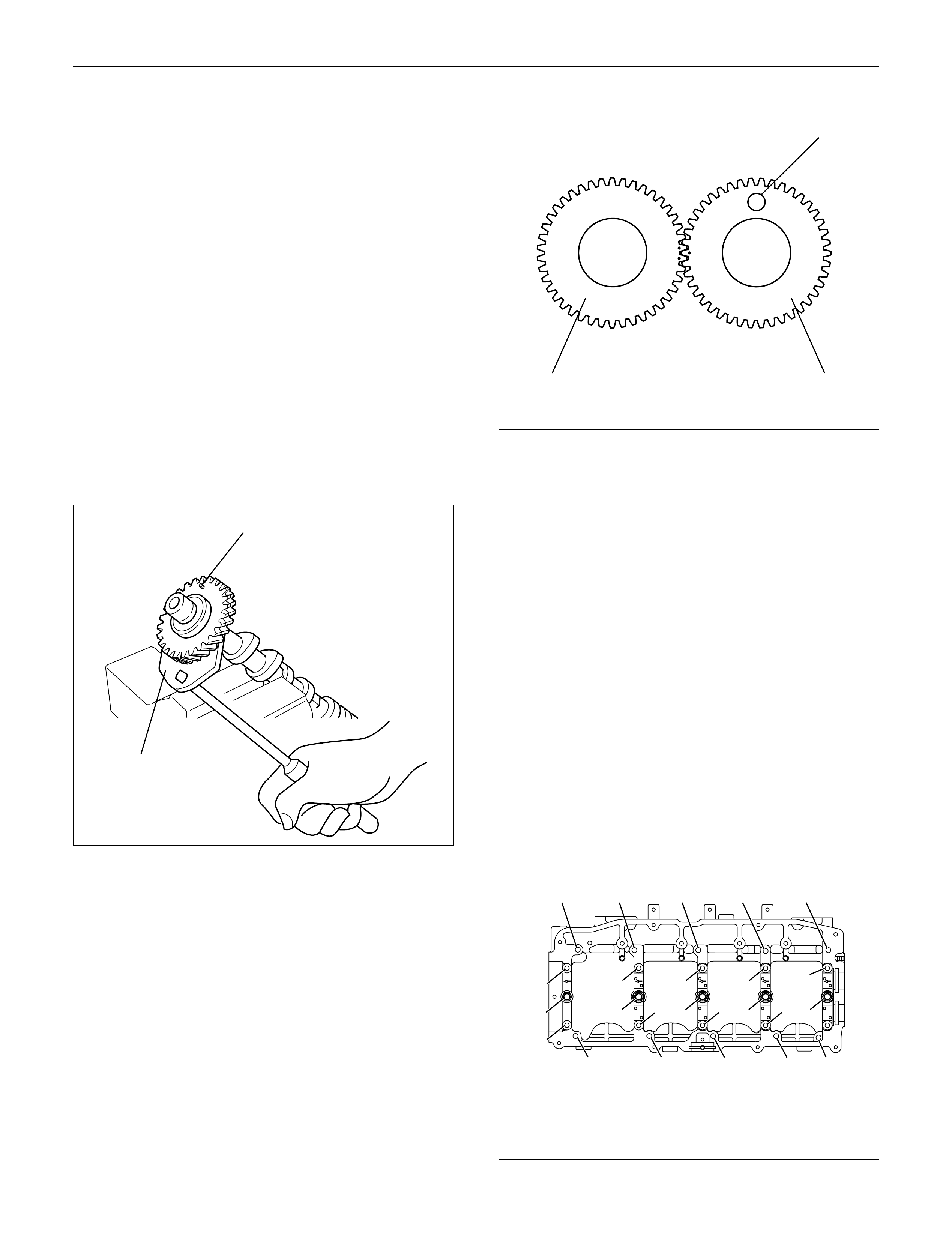
3) Apply engine oil to the camshaft gear tooth.
4) Apply engine oil to the journal on the camshaft
carrier.
5) Align the timing mark on the intake and exhaust
camshaft gear and put on the camshaft carrier.
Legend
(1) Locking pin
(2) Intake side camshaft gear
(3) Exhaust side camshaft gear
6) Apply liquid gasket (TB1207B or equivalent) to
No. 1 camshaft bracket matching surface.
7) Set No. 1 to No. 5 camshaft bracket on camshaft
carrier.
8) Temporarily tighten bracket bolts B and C.
Temporal Torque: 20 N·m (2.0 kg·m/14 lb ft)
9) Put gasket on the cylinder head.
10) Install camshaft carrier onto the cylinder head
and tighten bolts to specified torque.
Torque: A; 22 N·m (2.2 kg·m/16 lb ft)
B; 38 N·m (3.9 kg·m/28 lb ft)
C; 22 N·m (2.2 kg·m/16 lb ft)
D; 38 N·m (3.9 kg·m/28 lb ft)
•Remove locking pin.
1
2
014RW183
32
1
014RW184
CC
D
B
C
C
B
C
C
D
C
C
B
C
A
AA AA A
AAAA
011RW035
INSPECTION AND REPAIR
Make the necessary adjustments, repairs, and part
replacements if excessive wear or damage is
discovered during inspection.
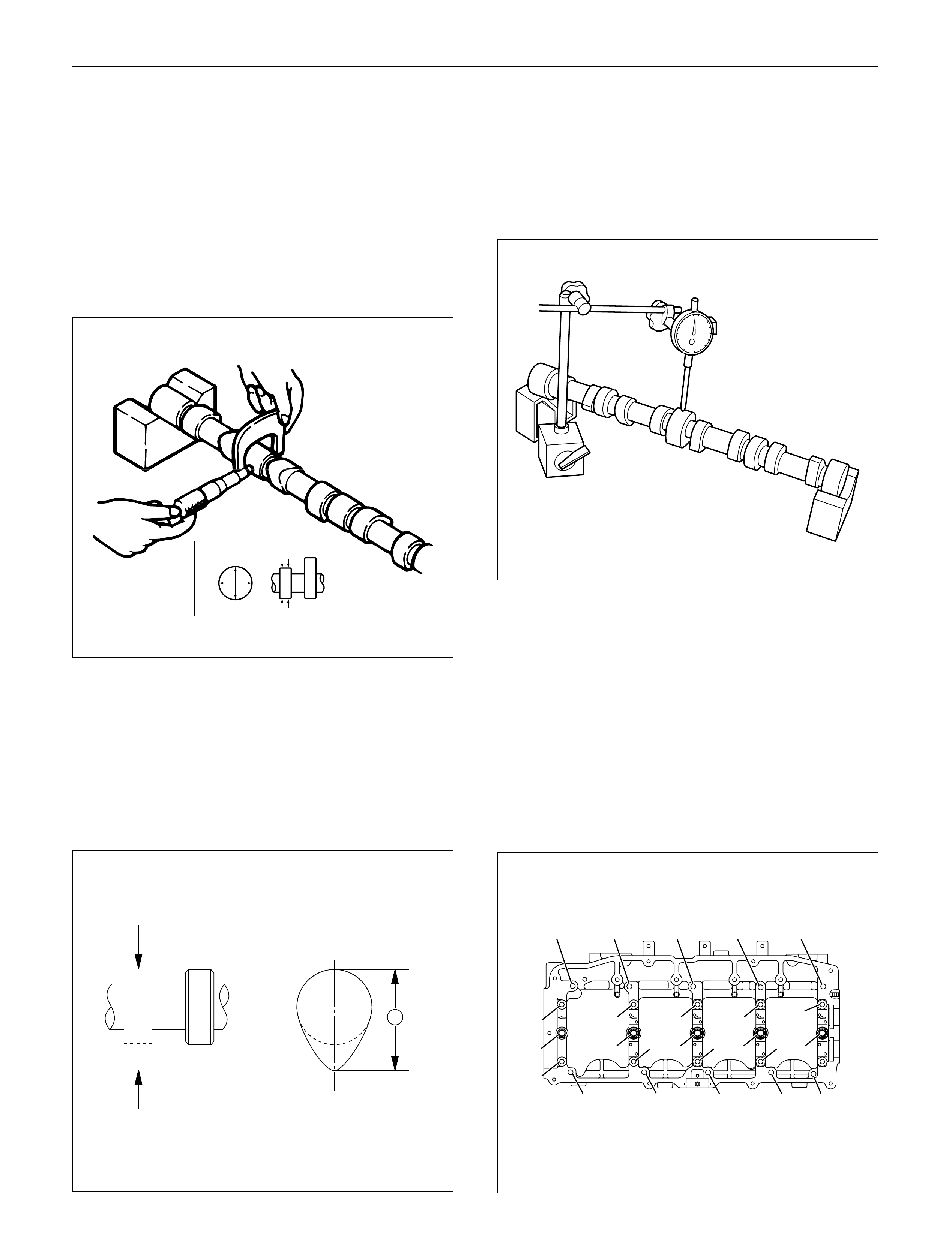
1. Camshaft Journal diameter
1) Use a micrometer to measure each camshaft
journal diameter in two directions (1) and (2). If
the measured value is less than the specified
limit, the camshaft must be replaced.
Standard: 29.939 – 29.96 mm (1.1787 – 1.1795 in)
Limit: 29.84 mm (1.17 in)
2. Cam Height
1) Measure the cam height (H) with a micrometer.
If the measured value is less than the specified
limit, the camshaft must be replaced.
Standard: IN 46.62 mm (1.8354 in)
EX 46.72 mm (1.8394 in)
Limit: IN 46.57 mm (1.8335 in)
EX 46.67 mm (1.8374 in)
3. Cam Run-Out
1) Mount the camshaft on V-blocks.
2) Measure the cam height (H) with a micrometer.
If the measured value is less than the specified
limit, the camshaft must be replaced.
Standard: 0.02 mm (0.0008 in) or less
Limit: 0.10 mm (0.0039 in)
4. Camshaft oil clearance
1) Clean the camshaft, camshaft bracket and
camshaft carrier.
2) Put camshaft carrier on the cylinder head.
3) Put camshaft on the camshaft carrier.
4) Put plastigauge on the camshaft journal.
5) Install camshaft bracket to original position and
tighten bolts to specified torque in the numerical
order shown in the illustration.
Torque: A; 22 N·m (2.2 kg·m/16 lb ft)
B; 38 N·m (3.9 kg·m/28 lb ft)
C; 22 N·m (2.2 kg·m/16 lb ft)
D; 38 N·m (3.9 kg·m/28 lb ft)
(1) Ft Rr
(2)
014RW179
H
012RW059
014RW171
CC
D
B
C
C
B
C
C
D
C
C
B
C
A
AA AA A
AAAA
110RW035
NOTE: Do not allow the camshaft to rotate.
6) Remove the camshaft bracket and measure the
plastigauge width and determine the oil
clearance. If the oil clearance exceeds the
specified limit, replace the camshaft carrier
and/or camshaft.
Oil clearance.
Standard: 0.040 – 0.082 mm (0.0016 – 0.0032 in)
Limit: 0.12 mm (0.0047 in)
7) Clean the plastigauge from the camshaft bracket
and camshaft carrier.
5. Camshaft thrust clearance.
1) Clean the camshaft, camshaft bracket and
camshaft carrier.
2) Put camshaft carrier on the cylinder head.
3) Put camshaft on the camshaft carrier.
4) Put plastigauge on the camshaft journal.
5) Install camshaft bracket to original position and
tighten bolts to specified torque in the numerical
order shown in the illustration.
Torque: A; 22 N·m (2.2 kg·m/16 lb ft)
B; 38 N·m (3.9 kg·m/28 lb ft)
C; 22 N·m (2.2 kg·m/16 lb ft)
D; 38 N·m (3.9 kg·m/28 lb ft)
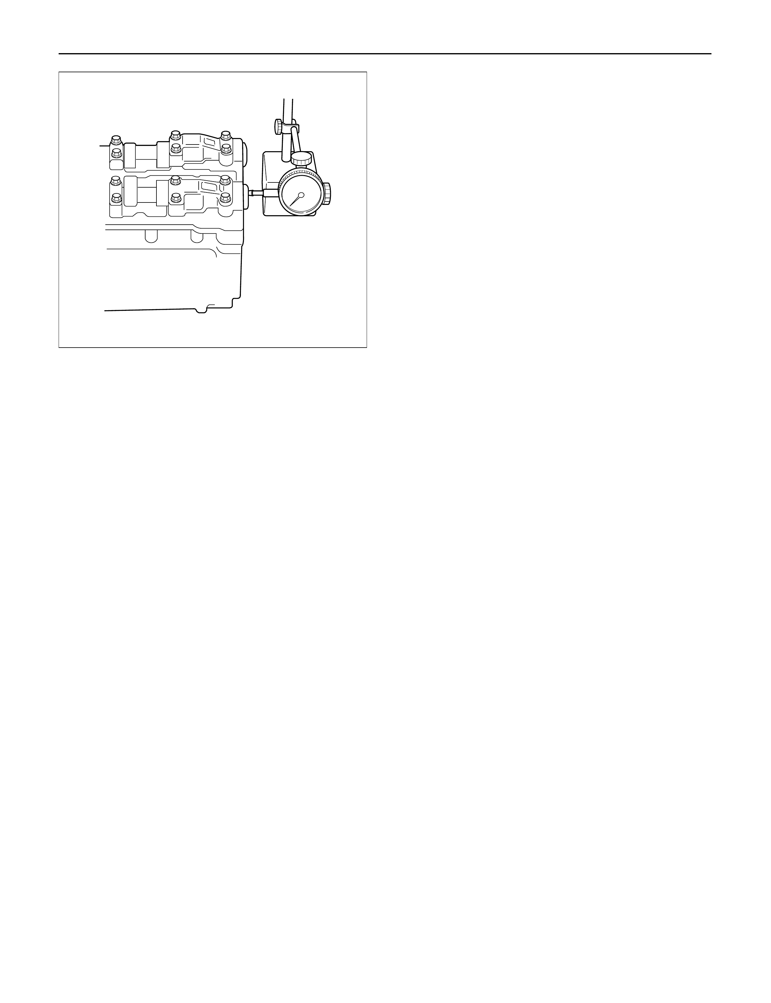
6) Use a dial indicator to measure the camshaft
thrust clearance. If the camshaft thrust
clearance exceeds the specified limit, replace
the camshaft carrier and/or camshaft.
Camshaft thrust clearance
Standard: 0.1 mm (0.0002 in)
Limit: 0.2 mm (0.0078 in)
13
7
6
5
12
15
2
3
10
9
20 8
19
23 22
4
16 1
11
25
24 21
17
18
011RW041
014RW185
CC
D
B
C
C
B
C
C
D
C
C
B
C
A
AA AA A
AAAA
011RW035
13
7
6
5
12
15
2
3
10
9
20 8
19
23 22
4
16 1
11
25
24 21
17
18
011RW041
014RW001
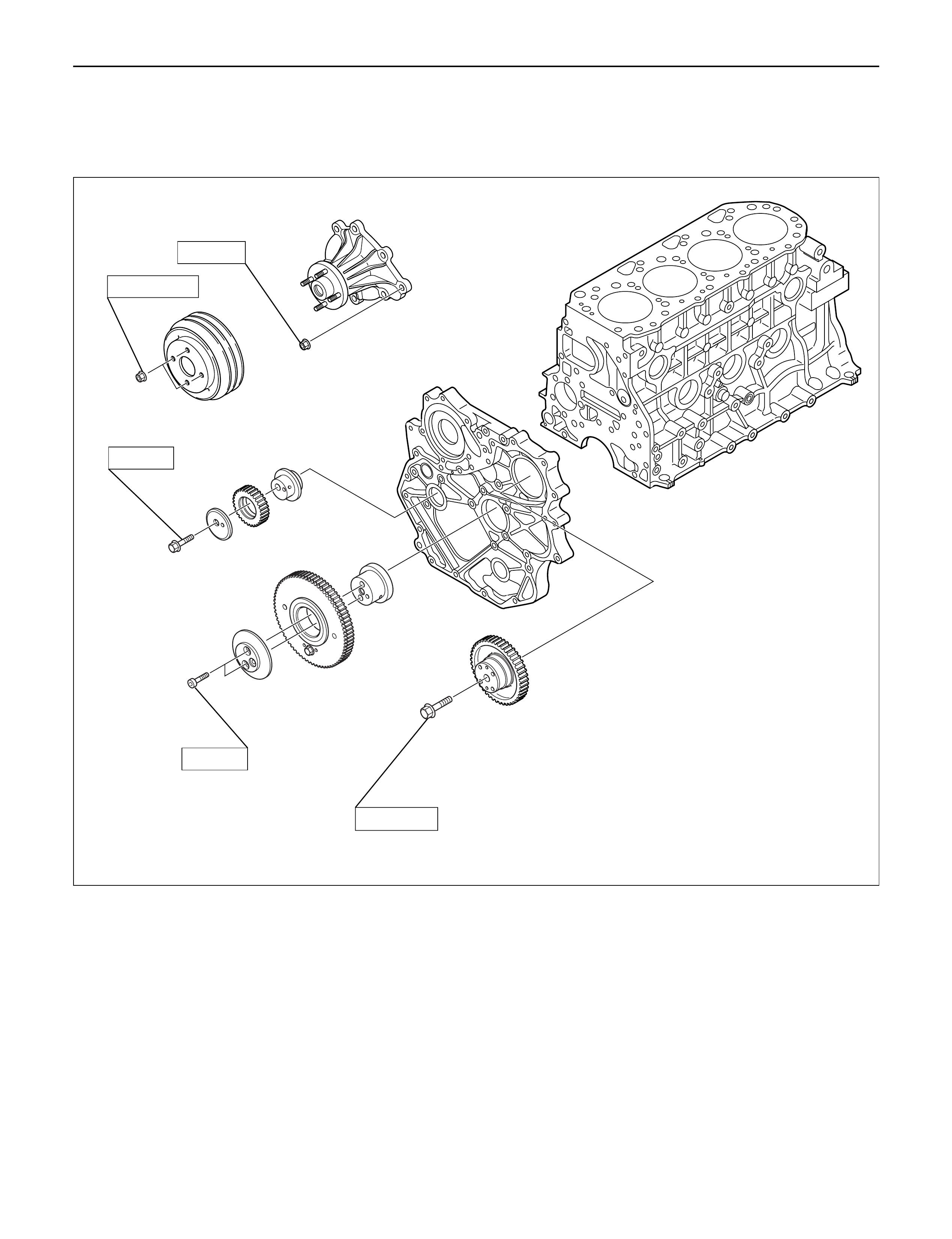
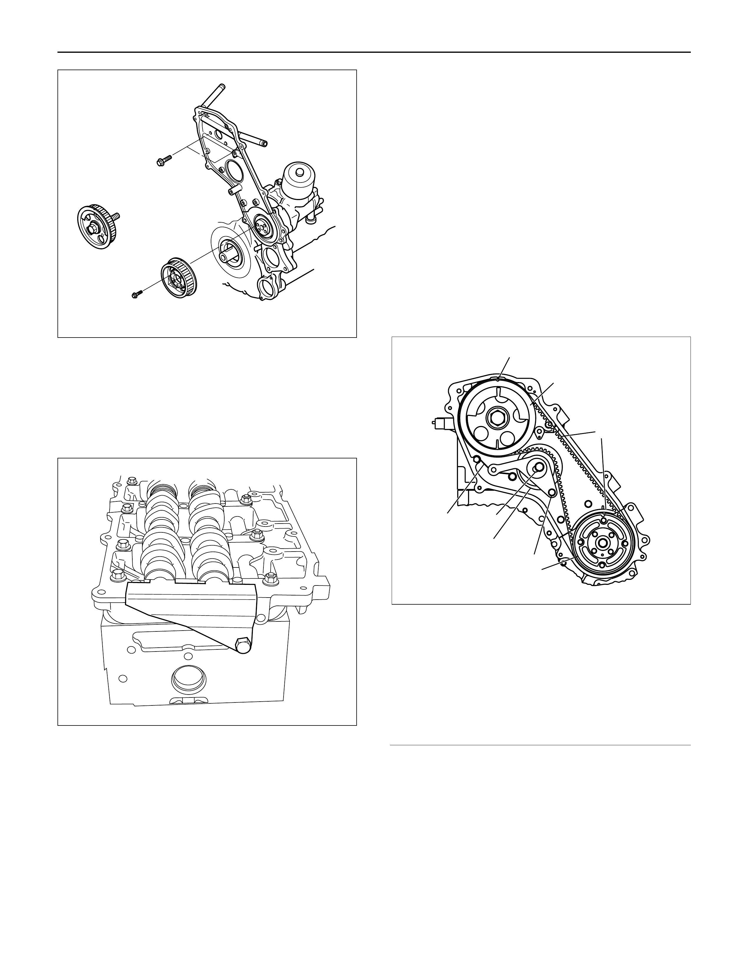
TIMING GEAR
REMOVAL
1. Loosen fixing bolt for generator and remove
generator assembly.
2. Remove fixing nuts, then remove cooling fan
assembly and fan pulley.
3. Remove crankshaft damper pulley.
4. Belt cover
1) Disconnect harness connector of CMP
(camshaft position) sensor.
2) Remove CMP sensor.
3) Remove belt cover.
5. Loosen belt tensioner to remove timing belt.
6. Remove camshaft pulley.
7. Remove high pressure oil pump pulley.
8. Remove front plate.
9. Remove vacuum pump.
10. Remove power steering pump.
11. Remove timing gear case cover assembly.
12. Idle gear A.
1) Set two bolts to sub gear of idle gear A and turn
it to align the tooth of idle gear A then lock them
by bolt as show in the illustration.
2) Remove idle gear A fixing bolts.
3) Remove idle gear A.
Legend
(1) Sub-Gear
(2) Main Gear
(3) Bar
(4) Locking Bolt
2
3
4
5
8
76
9
1
020RW028
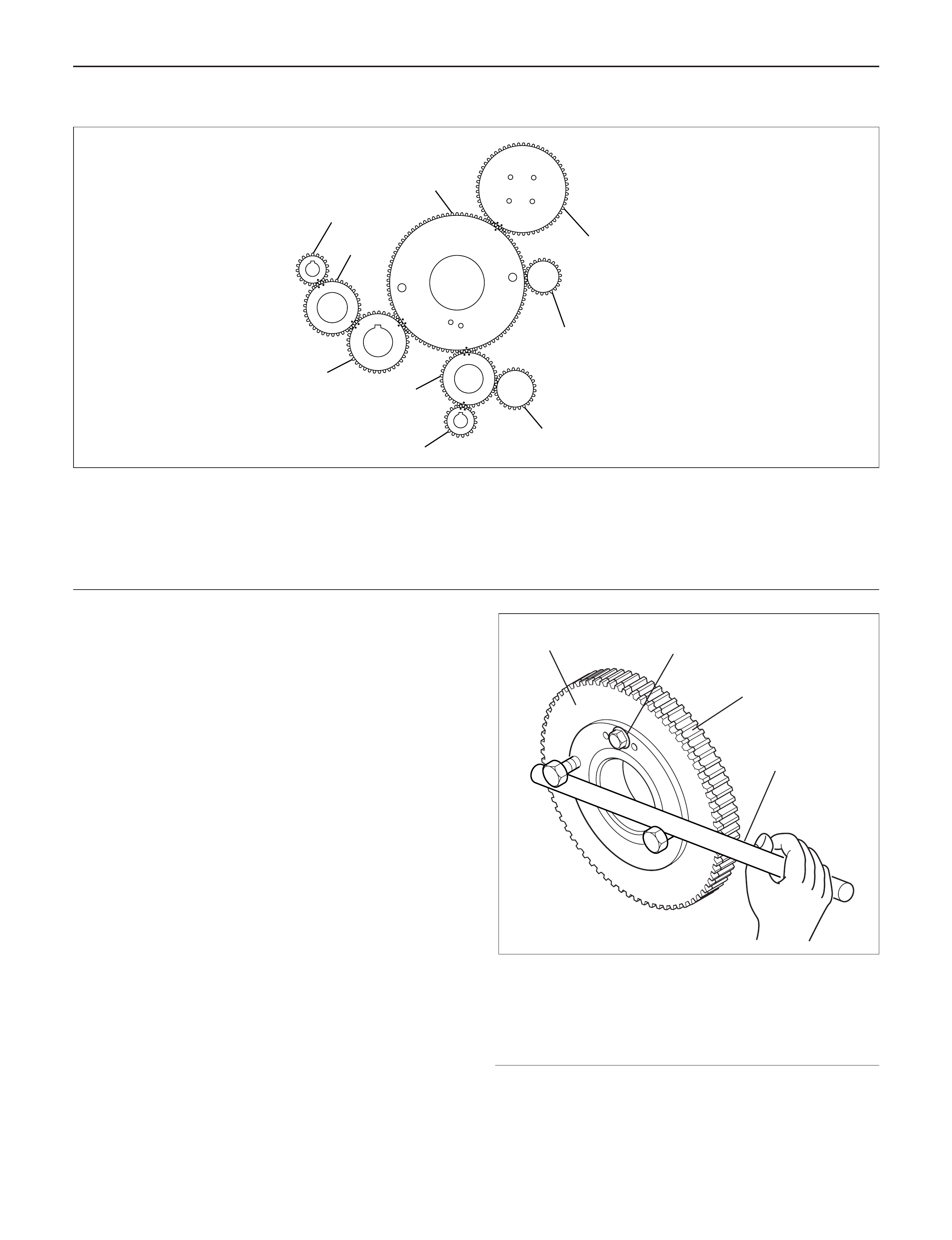
Legend
(1) Idle Gear A
(2) High Pressure Oil Pump Gear
(3) Vacuum Pump Gear
(4) Power Steering Pump Gear
(5) Balance Gear LH
(6) Idle Gear C
(7) Crankshaft Gear
(8) Balance Gear RH
(9) Idle Gear B
4
1
2
3
014RW177
Legend
(1) Bolt
(2) Retainer
(3) Idle Gear A
(4) Idle Gear A Shaft
(5) Align Mark
(6) Crankshaft Gear
(7) O-Ring
13. Idle gear C
1) Use the special tool on idle gear C, turning the
sub gear to align the teeth, then set lock pin.
2) Remove idle gear C fixing bolt then remove the
idle gear C with flange.
Camshaft Gear Tool : 5-8840-2591-0
Legend
(1) Lock pin
(2) Camshaft Gear Tool
Legend
(1) Bolt
(2) Retainer
(3) Idle Gear C
(4) Idle Gear C Shaft
(5) Align Mark
(6) Align Mark
(7) Idle Gear A
(8) Balance Shaft Gear LH
(9) Timing Mark
14. Idle gear B
1) Loosen idle gear B fixing bolt to remove idle
gear B with flange.
Legend
(1) Bolt
(2) Retainer
(3) Idle Gear B
(4) Idle Gear B Shaft
(5) Align Mark
3
65
4
3
2
1
7
1
7
014R200007
1
2
014RW181
12345
5
6
6
8
8
3
7
7
9
9
9
014RW175
3
5
5
4
3
2
1
014R200008
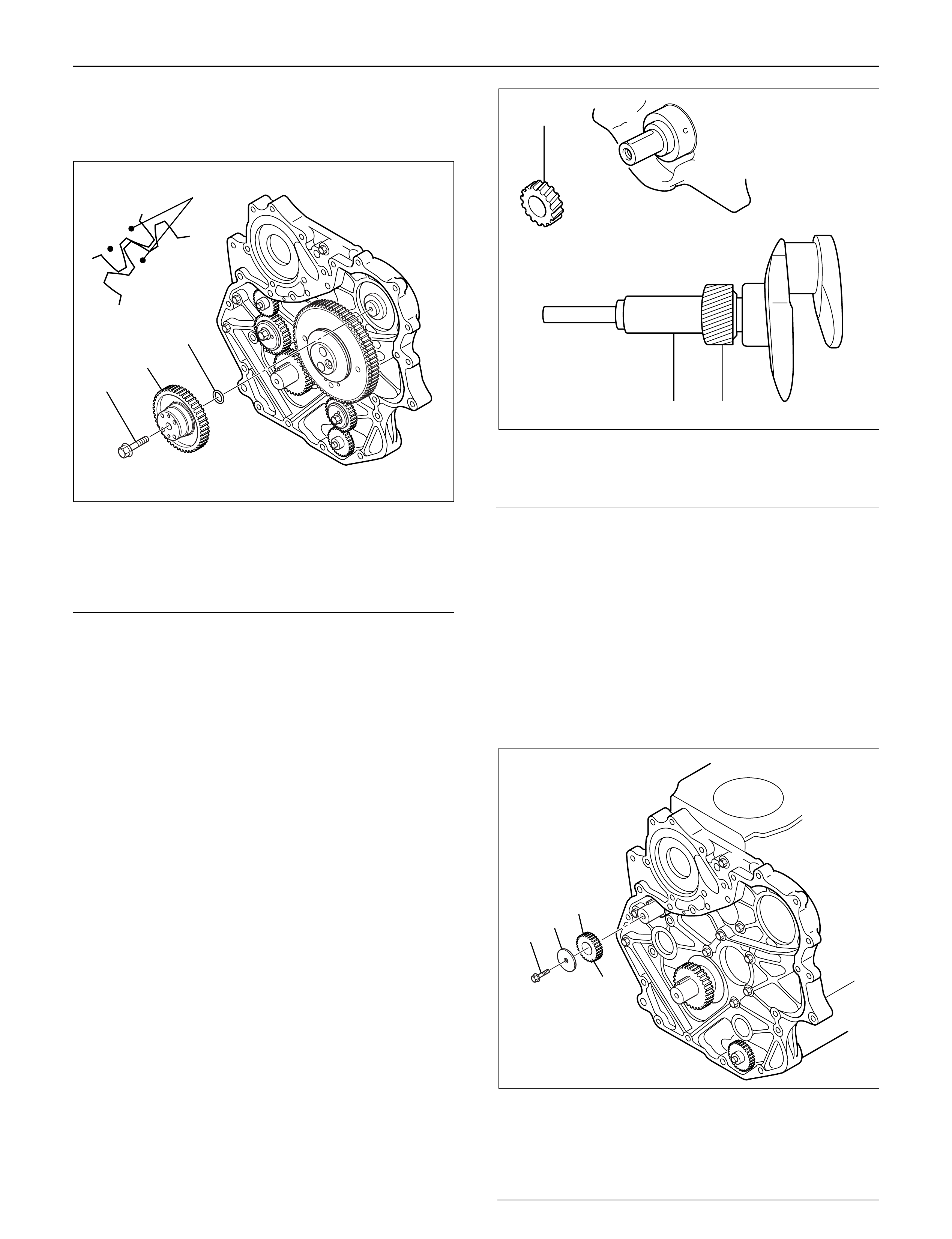
15. High pressure oil pump
1) Remove oil pump gear fixing bolt then remove
oil pump.
Legend
(1) O-Ring
(2) High Pressure Oil Pump Gear
(3) Bolt
(4) Timing Mark
16. Remove balance shaft gear LH. and RH.
17. Remove crankshaft gear.
INSTALLATION
1. Crankshaft gear
1) Force key into the crankshaft and insert
crankshaft gear with the crankshaft gear key
groove set on the key.
Legend
(1) Crankshaft Gear Installer
(2) Crankshaft Gear
2. Balance shaft gear
1) Install the balance shaft gear RH to balance
shaft, tighten center bolt to the specified torque.
Torque : 32 N·m (3.3 kg·m/24 lb ft)
2) Install thrust plate for balance shaft LH before
installing the balance shaft gear LH.
Torque : 25 N·m (2.5 kg·m/18 lb ft)
3) Install balance shaft gear LH to balance shaft,
tighten center bolt to the specified torque.
Torque : 32 N·m (3.3 kg·m/24 lb ft)
Legend
(1) Center Bolt
(2) Plate
(3) Balance Shaft Gear RH
(4) Timing Mark
4
GEAR:O/PUMP
IDLE GEAR A
1
2
3
040RW005
12
2
012RW066
3
4
2
1
014RW173
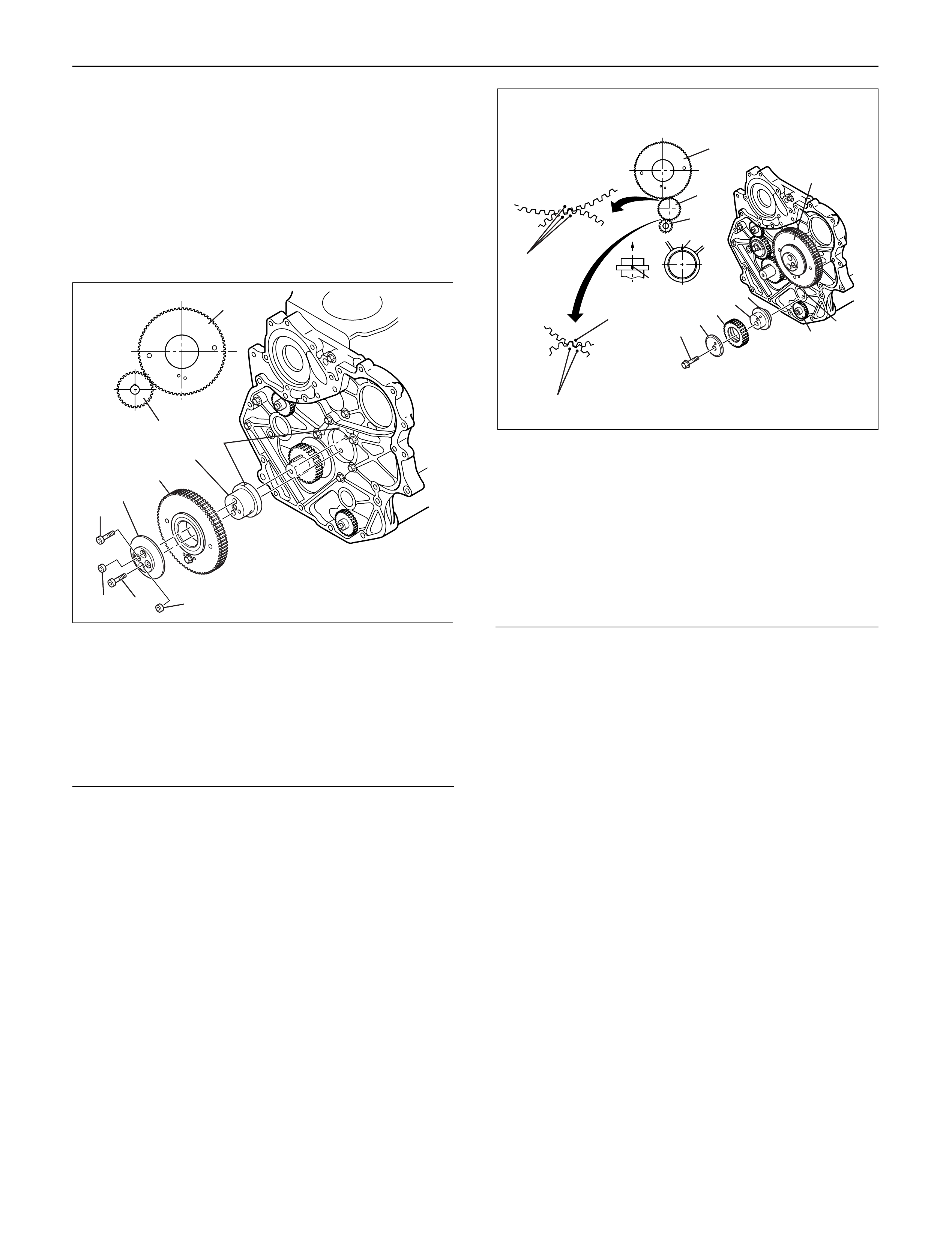
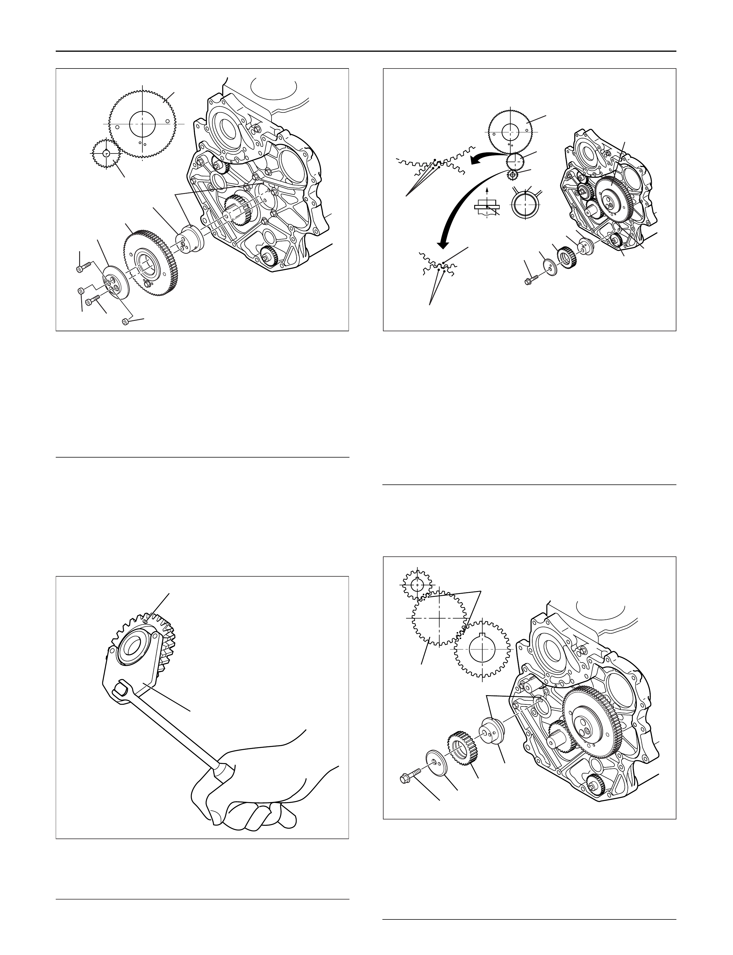
3. Idle gear A
1) Insert idle gear A shaft to align alignment mark
between idle gear A shaft and timing gear case.
2) Apply engine oil to the shaft surface.
3) Install the idle gear A to align the timing mark
with the crankshaft gear.
4) Install the flange, tighten bolts to the specified
torque.
Torque: 25 N·m (2.5 kg·m/18 lb ft)
Legend
(1) Bolt
(2) Retainer
(3) Idle Gear A
(4) Idle Gear A Shaft
(5) Align Mark
(6) Crankshaft Gear
(7) O-Ring
NOTE: Conform not difference timing marks between
each others.
4. Idle gear C
1) Insert idle gear C shaft to align alignment mark
between idle gear C shaft and timing gear case.
2) Apply engine oil to the shaft surface.
3) Align timing mark on idle gear C with balance
shaft gear LH and idle gear A timing marks, then
insert idle gear C.
4) Set position of idle gear C flange with a dowel
pin, tighten bolt to the specified torque.
Torque: 25 N·m (2.5 kg·m/18 lb ft)
Legend
(1) Bolt
(2) Retainer
(3) Idle Gear C
(4) Idle Gear C Shaft
(5) Align Mark
(6) Align Mark
(7) Idle Gear A
(8) Balance Shaft Gear LH
(9) Timing Mark
5. Idle gear B
1) Insert idle gear B shaft to align alignment mark
between idle gear B shaft and timing gear case.
2) Apply engine oil to the shaft surface.
3) Align timing mark on idle gear B with balance
shaft gear RH and crankshaft gear timing marks,
then insert idle gear B.
4) Install flange and tighten the bolt to the specified
torque.
Torque: 51 N·m (5.2 kg·m/38 lb ft)
3
65
4
3
2
1
7
1
7
014R200007
12345
5
6
6
8
8
3
7
7
9
9
9
014RW175
Legend
(1) Bolt
(2) Retainer
(3) Idle Gear B
(4) Idle Gear B Shaft
(5) Align Mark
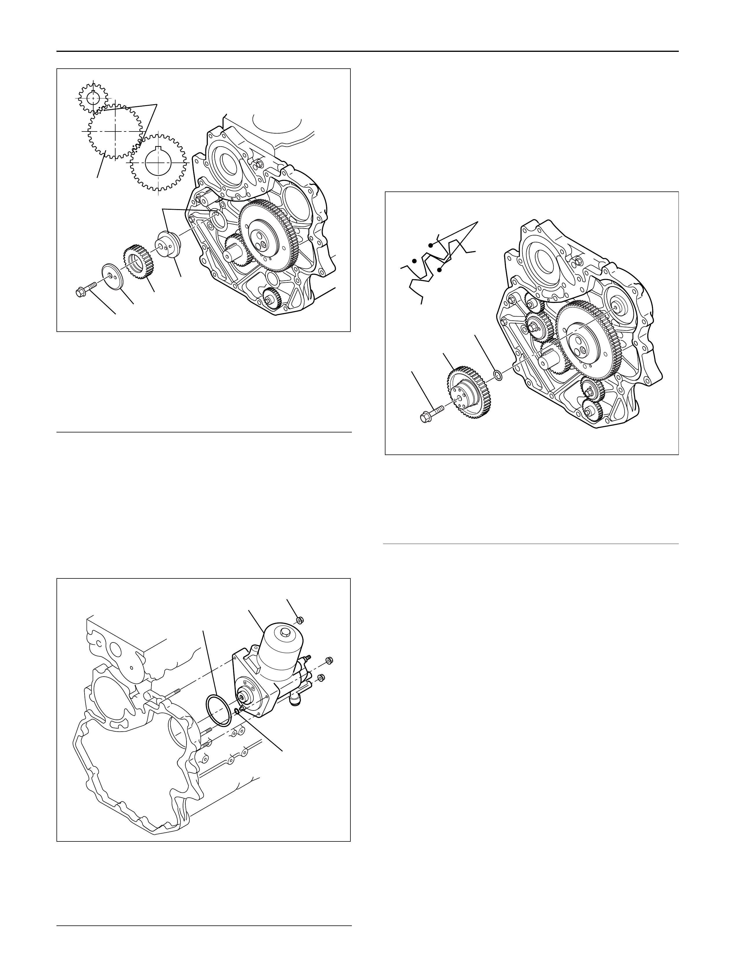
6. High pressure oil pump
1) Install O-ring on the high pressure oil pump.
2) Install the high pressure oil pump to the timing
gear case, tighten the nut to the specified
torque. Apply Loctite No. 262 to the stud bolts.
Torque: 20 N·m (2.0 kg·m/14 lb ft)
NOTE: Be sure to set O-ring completely.
Legend
(1) O-ring (large)
(2) High pressure oil pump
(3) Nut
(4) O-ring (small)
7. High pressure oil pump
1) Install O-ring on the oil pump shaft with grease
and install the gear with the idle gear A timing
mark set at the oil pump gear timing mark.
2) Tighten center bolt to the specified torque.
Torque: 75 N·m (7.6 kg·m / 55 lb ft)
NOTE: Be sure to align timing marks with each other.
Legend
(1) O-ring
(2) High Pressure Oil Pump Gear
(3) Center Bolt
(4) Timing Mark
8. Remove lock from idle gear.
1) Remove lock bolt from idle gear A and remove
lock pin from idle gear C.
9. Timing gear case assembly
1) Clean fixing surface of timing gear case.
2) Install the gasket on the idle gear rear side end.
3) Apply liquid gasket (TB1207C or equivalent) to
the timing gear case fitting surface.
NOTE: Be sure to apply liquid gasket evenly.
4) Install timing gear case and tighten bolts to the
specified torque.
Torque: 20 N·m (2.0 kg·m / 14 lb ft)
NOTE: Must install within 5 minutes after applying liquid
gasket.
3
5
5
4
3
2
1
014R200008
1
2
4
3
040RW007
4
GEAR:O/PUMP
IDLE GEAR A
1
2
3
040RW005
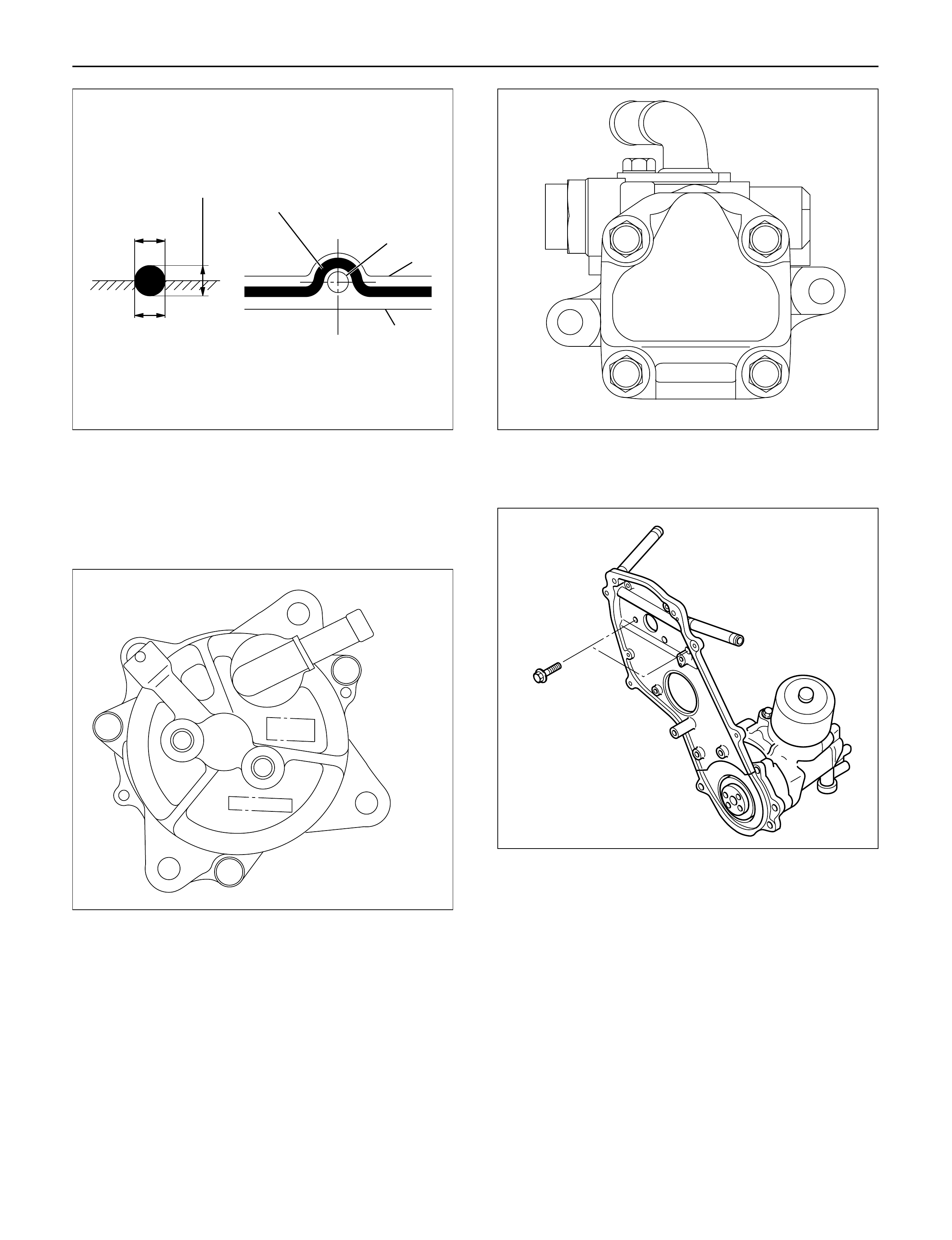
10. Vacuum pump
1) Install vacuum pump and tighten bolts to
specified torque.
Torque: 25 N·m (2.5 kg·m / 18 lb ft)
2) Install noise insulator cover.
11. Power steering pump (P/S)
1) Install P/S pump.
Torque: 22 N·m (2.2 kg·m / 16 lb ft)
12. Install front plate.
Torque: 20 N·m (2.0 kg·m / 14 lb ft)
13. High pressure oil pump pulley.
1) Install oil pump pulley and tighten to specified
torque.
Torque:10 N·m (1.0 kg·m / 87 lb in)
2
2~2.5mm
2~2.5mm
Apply liquid gasket around inside
of the bolt hole
Bolt hole
Inside
Outside
F06HX00001
052RW001
430RW017
012RW035
14. Camshaft pulley
1) Align TDC mark with crankshaft pulley and gear
case cover.
2) Set camshaft stopper on the end of intake and
exhaust camshaft.
Camshaft Stopper: 5-8840-2592-0
3) Install key to camshaft and install camshaft
pulley.
4) Apply engine oil to camshaft pulley fixing bolt
and tighten bolt with angular tightening method.
First step: 40 N·m (4.1 kg·m / 30 lb ft)
Second step: 60° to 90°
15. Timing belt
1) Install tensioner and tighten the bolt temporarily.
2) Align timing mark with camshaft pulley timing
mark and timing gear case timing mark.
3) Set No.1 cylinder TDC position.
4) Install the timing belt in the following order
camshaft pulley, oil pump pulley, tensioner.
NOTE:
1) It is recommended for easy installation that the belt
be secured with a double clip after it is installed to
each pulley.
2) The “ISUZU” mark should be read from the front of
the engine when installing the timing belt.
5) Install the belt tensioner.
6) Conform not phase difference each pulley.
7) Tension the timing belt with two turns of the
crankshaft.
8) Tighten the tensioner bolt in order A to B to the
specified torque.
Torque: Bolt A 50 N·m (5.1 kg·m/37 lb ft)
Bolt B 20 N·m (2.0 kg·m/14 lb ft)
Legend
(1) Align Mark
(2) Camshaft Pulley
(3) Timing Belt
(4) Oil Pump Pulley
(5) Tension Bolt B
(6) Tensioner Assy
(7) Tensioner Bolt A
(8) Tensioner Spring
16. CMP sensor bracket
1) Install CMP sensor bracket and tighten bolt to
the specified torque.
Torque: 20 N·m (2.0 kg·m / 14 lb ft)
17. Timing belt cover
1) Install timing belt cover and tighten bolt to the
specified torque.
Torque: 9 N·m (0.9 kg·m / 78 lb in)
2) Tighten CMP sensor to the specified torque.
Torque: 9 N·m (0.9 kg·m / 78 lb in)
012RW036
012RW099
1
2
3
8
6
7
4
5
F06R200006
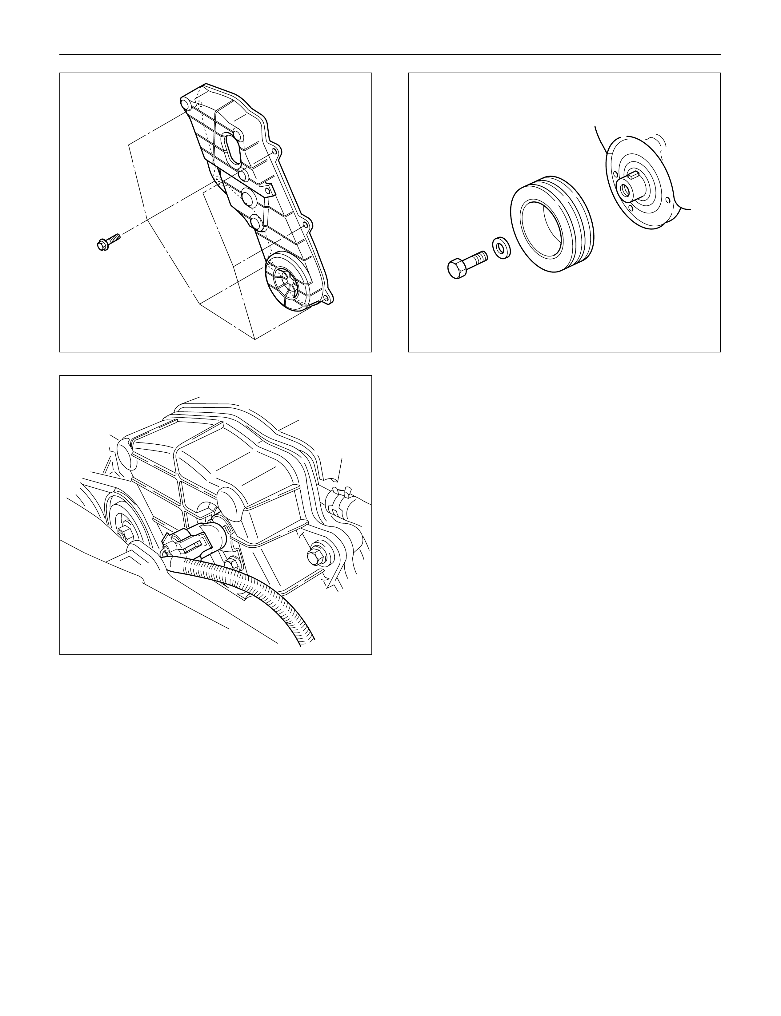
18. Crankshaft damper pulley
1) Insert damper pulley with the crankshaft key
groove set on the key.
2) Tighten damper pulley bolt to the specified
torque.
Torque: 216 N·m (22 kg·m / 159 lb ft)
19. Cooling fan Assembly
1) Install the cooling fan assembly to the fan pulley,
tighten the nuts to the specified torque.
Torque: 8 N·m (0.8 kg·m / 69 lb in)
20. AC generator drive belt.
1) Temporarily tighten generator fixing bolts and
belt tensioner adjustment plate.
2) Tension the generator drive belt then tighten the
generator fixing bolt.
Torque: 40 N·m (4.1 kg·m / 30 lb ft)
3) Tighten the belt tensioner adjustment plate bolt.
Torque: 20 N·m (2.0 kg·m / 14 lb ft)
012RW039
014RW163
012RW032
VALVE STEM SEAL, VALVE SPRING AND ADJUSTER
REMOVAL
1.Disconnect battery ground cable.
2.Drain engine coolant.
3.Remove the air duct from between air cleaner and
turbocharger.
4.Remove intercooler assembly.
Refer to “Intercooler” in this manual.
5. Remove oil level gauge guide assembly.
6. Disconnect PCV hose.
7. Disconnect EGR vacuum hose.
8. Disconnect harness connectors around the cylinder
head such as the injector, CMP sensor, MAP
sensor, EGR sensor, EVRV, IAT sensor, A/C
compressor, TP stepping motor, TP sensor and fuel
temperature sensor etc.
9. Remove A/C compressor assembly.
10. Remove A/C compressor bracket.
11. Remove generator assembly and take out drive
belt.
12. Remove heat protector, remove exhaust valve
assembly.
13. Remove water cooling hose and lubrication pipe for
turbocharger.
14. Remove turbocharger assembly.
15. Remove hose between thermostat and radiator.
16. Remove noise insulator cover of cylinder head.
NOTE: Do not damage injector harness.
17. Remove high pressure oil pipe.
18. Remove timing belt cover.
19. Remove CMP sensor bracket.
20. Remove timing belt tensioner then remove timing
belt.
21. Remove camshaft pulley.
22. Remove front plate.
23. Remove engine coolant pipe between cylinder
head and water pump.
1
2
3
4
5
6
9
10
7
8
011RW031
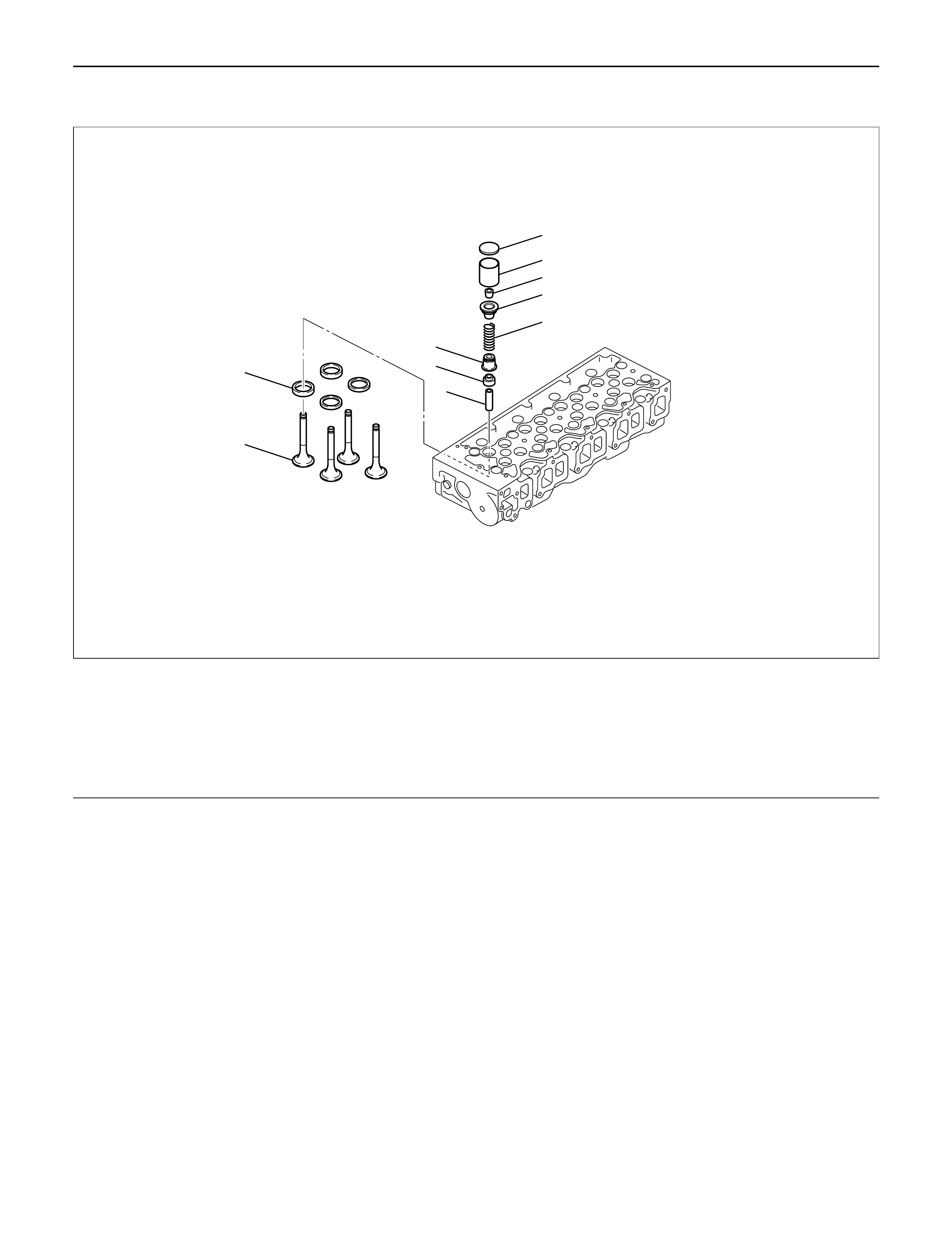
Legend
(1) Adjuster
(2) Tappet
(3) Split Collar
(4) Spring Seat Upper
(5) Valve Spring
(6) Spring Seat Lower
(7) Valve Stem Seal
(8) Valve Guide
(9) Valve Seat
(10) Valve
24.Remove fuel pipe between fuel pump and intake
manifold.
25.Remove fuel return pipe from rear of cylinder head.
26.Remove intake manifold assembly.
27.Disconnect glow plug harness and remove glow
plug.
28.Remove cylinder head cover.
29.Remove injector harness connector.
30.Disconnect harness connector from oil pressure
sensor and oil temperature sensor on the oil rail.
31.Remove injector harness assembly.
32.Remove injector clamp.
33.Remove injector is fixed bolts.
34.Remove injector assembly.
35.Remove oil rail.
36.Remove camshaft carrier assembly with camshaft.
37.Remove cylinder head assembly.
38.Disassemble valve spring according to the following
method.
1)Use valve spring compressor then remove split
collars.
2)Valve spring compressor: 5-8840-2441-0
NOTE: Put removed valve spring in order of cylinder
number.
39.Valve stem seal.
1)Use a screwdriver or pliers to remove valve
stem seal.
NOTE: Do not reuse removed valve stem seal.
INSPECTION AND REPAIR
Make the necessary adjustments, repairs and part
replacements if excessive wear or damage is
discovered during inspection.
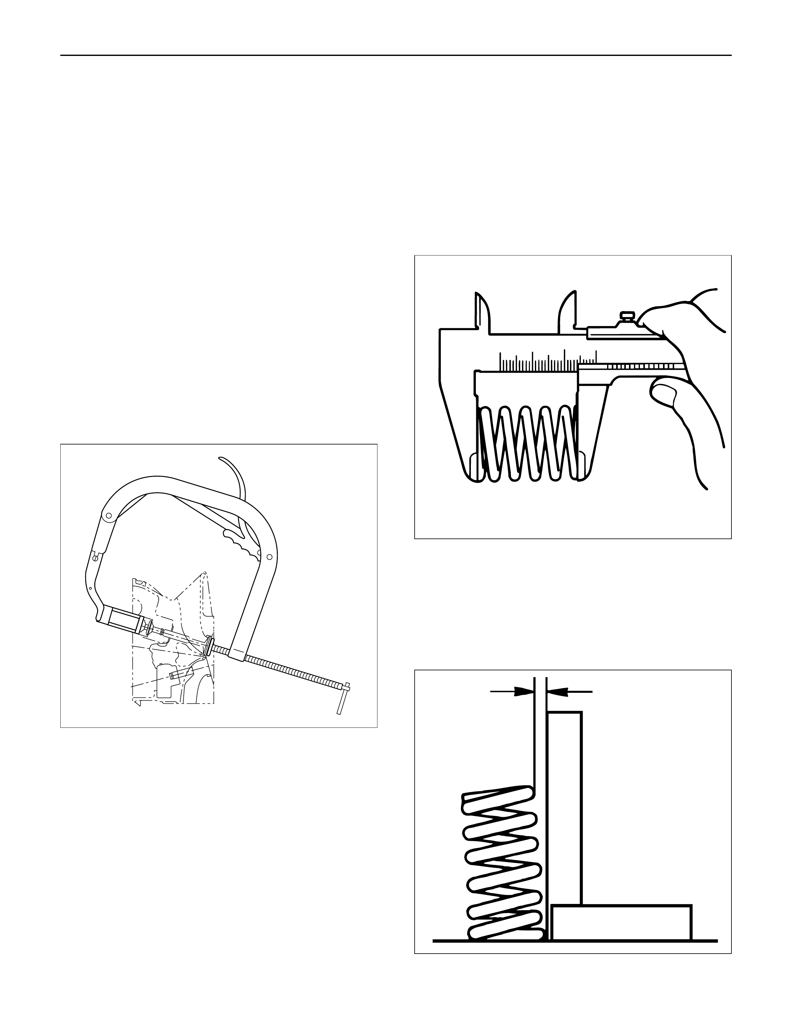
Valve spring
CAUTION: Visually inspect the valve springs and
replace them if damage or abnormal wear is
evident.
1. Free height
1) Measure the free height of the springs. The
springs must be replaced if the height is below
the specified limit.
Standard: 45.85 mm (1.8051in)
Limit: 43.9 mm (1.7283 in)
2. Squareness
1) Measure the valve spring squareness with a
steel square.
2) Replace the valve springs if the measured value
exceeds the specified limit.
Limit: 1.6 mm (0.063 in)
014rw042
014rs004
014rs005

3.Spring tension
1)Use a spring tester to compress the springs to
the installed height. Measure the compressed
spring tension.
2)Replace the springs if the measured tension is
below the specified limit.
Standard: 236.0 N (24 kg/53 lb)
Limit: 205.0 N (21 kg/46 lb)
Valve Guide
CAUTION: Taking care not to damage the valve seat
contact surface, when removing carbon adhering to
the valve head.
Carefully inspect the valve stem for scratching or
abnormal wear. If these conditions are present, the
valve and the valve guide must be replaced as a set.
1. Valve Guide Clearance
1) Measure the valve stem diameter with a
micrometer.
If the valve stem diameter is less than the
specified limit, the valve and the valve guide
must be replaced as a set.
Diameter of Valve stem:Inlet
Standard: 6.959 – 6.977 mm (0.2740 – 0.2747 in)
Limit: 6.92 mm (0.2724 in)
Diameter of Valve stem:Exhaust
Standard: 6.952 – 6.97 mm (0.2737 – 0.2744 in)
Limit: 6.90 mm (0.2717 in)
2) Measure the inside diameter of the valve guide
with a micrometer.
3) Subtract the measured outer diameter of the
valve stem from the measured inner diameter of
the valve guide.
If the valve exceeds the specified limit, the valve
and the valve guide must be replaced as a set.
Inlet clearance
Standard: 0.023 – 0.053 mm (0.0009 – 0.0021 in)
Limit: 0.19 mm (0.0075 in)
Exhaust clearance
Standard: 0.03 – 0.063 mm (0.0012 – 0.0025 in)
Limit: 0.20 mm (0.0079 in)
014RS006
014RS007
Valve Guide Replacement
1. Using the special tool, drive out the valve guide
from the combustion chamber side.
Valve guide replacer: 9-8523-1212-0
2. Apply engine oil to the outside of the valve guide.
Using the special tool, drive in a new valve guide
from cylinder head upper face side, and check the
valve guide height.
Valve guide replacer: 9-8523-1212-0
Height: 8.0 mm (0.315 in)
NOTE: If the valve guide has been removed, both the
valve and the valve guide must be replaced as a set.
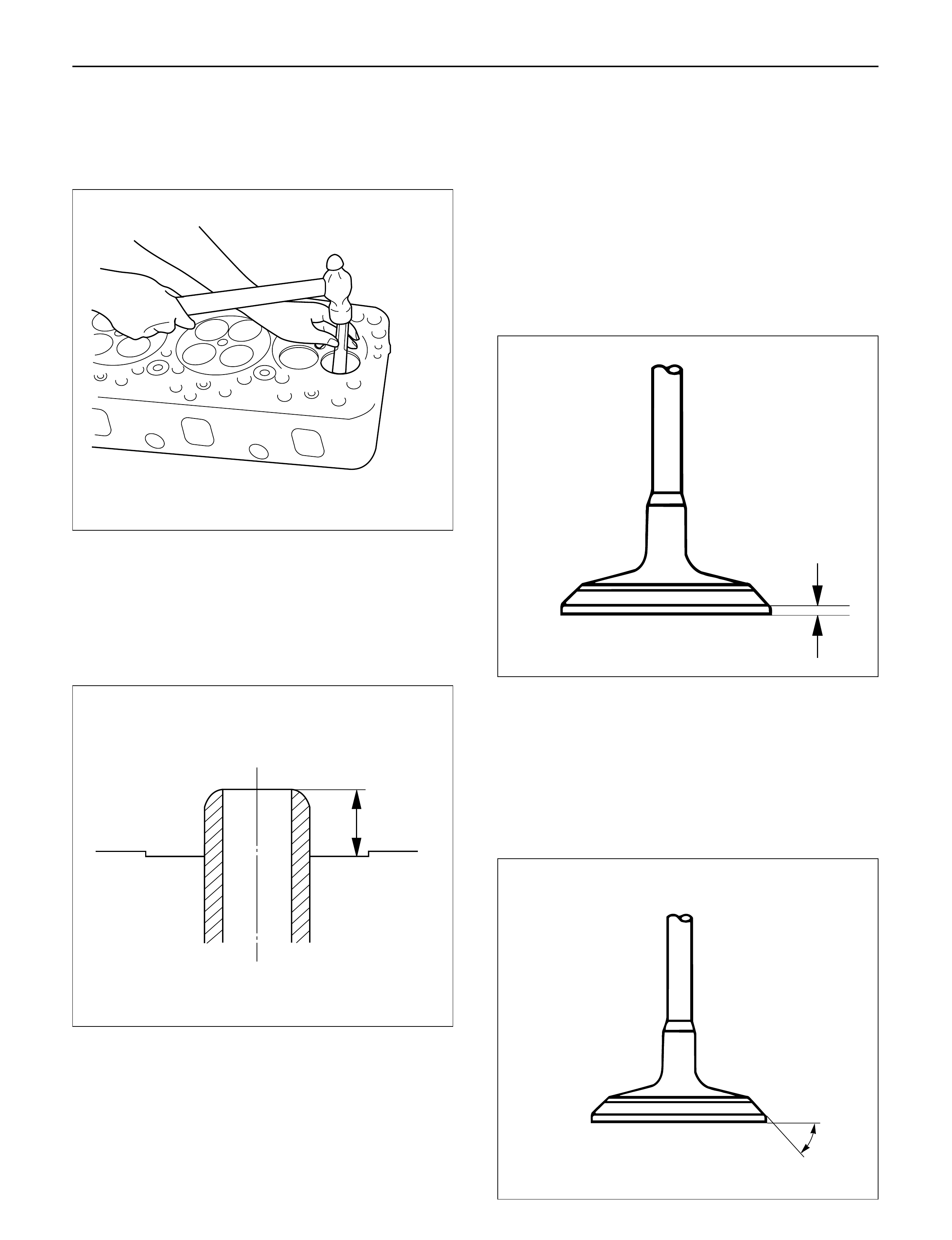
Valve Thickness
1. Measure the valve thickness.
2. If the measured value is less than the specified
limit, the valve and the valve guide must be
replaced as a set.
Inlet
Standard: 1.2 mm (0.0472 in)
Limit: 1.1 mm (0.0433 in)
Exhaust
Standard: 1.2 mm (0.0472 in)
Limit: 1.1 mm (0.0433 in)
Contact surface angle on valve seat on
valve
1. Measure contact surface angle on valve seat.
2. If the measured value exceeds the limit, replace
valve, valve guide and valve seat as a set.
Standard: 68°
011RW001
012RW052
012RW060
014RW018
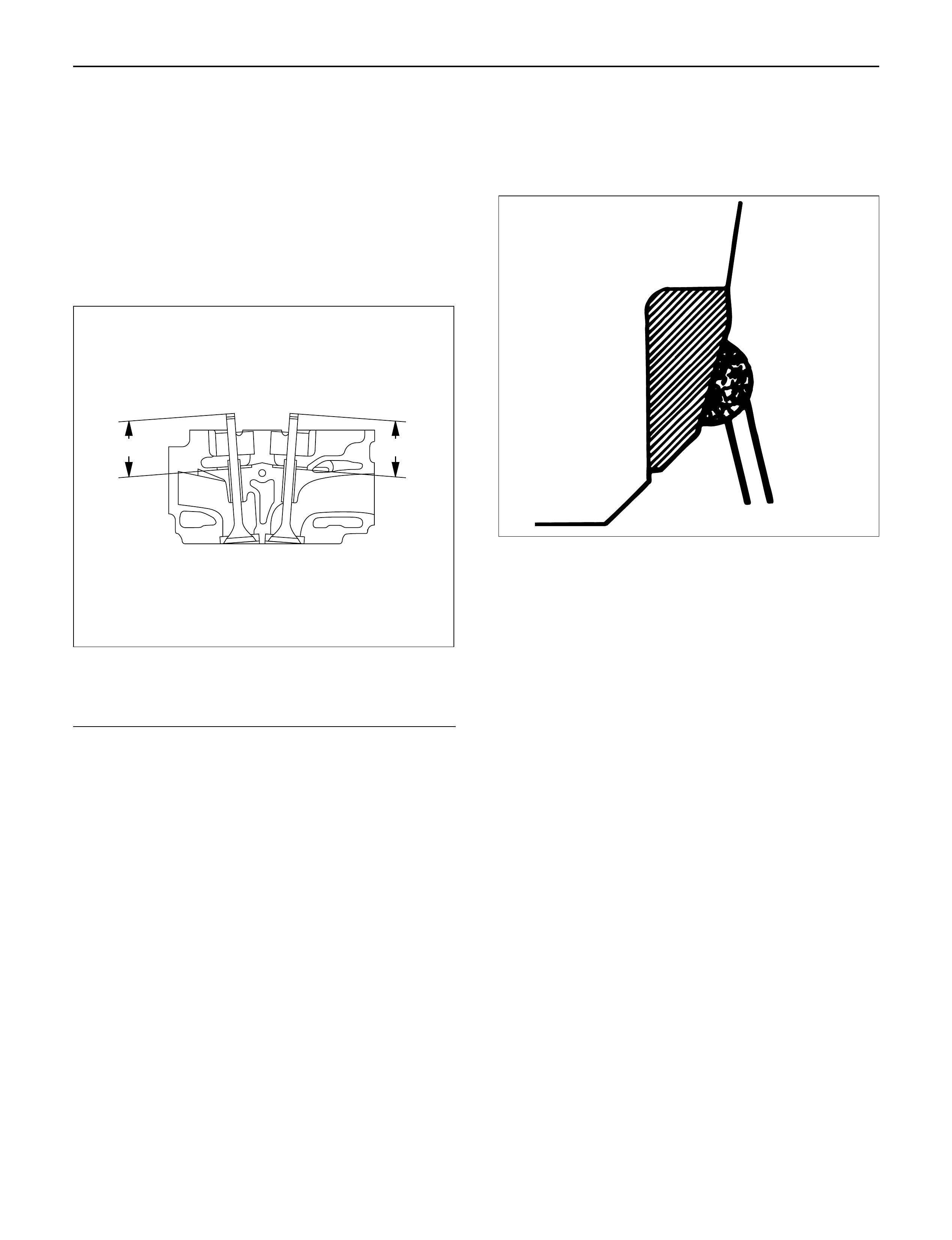
Valve Depression
1. Measure the valve stem height from the upper
surface of the cylinder head as shown in the
illustration.
Standard:
Intake side 35.59 mm (1.4012 in)
Exhaust side 35.49 mm (1.3972 in)
Limit:
Intake side 35.74 mm (1.4071 in)
Exhaust side 35.64 mm (1.4031 in)
Legend
(1) Intake Side
(2) Exhaust Side
Valve Contact Width
1. Check the valve contact faces for roughness and
unevenness. Make the valve contact surfaces
smooth.
2. Measure the valve contact width.
If the measured value exceeds the specified limit,
the valve seat insert must be replaced.
Inlet
Standard: 2.1 mm (0.0827 in)
Limit: 2.6 mm (0.1024 in)
Exhaust
Standard: 2.0 mm (0.0787 in)
Limit: 2.5 mm (0.0984 in)
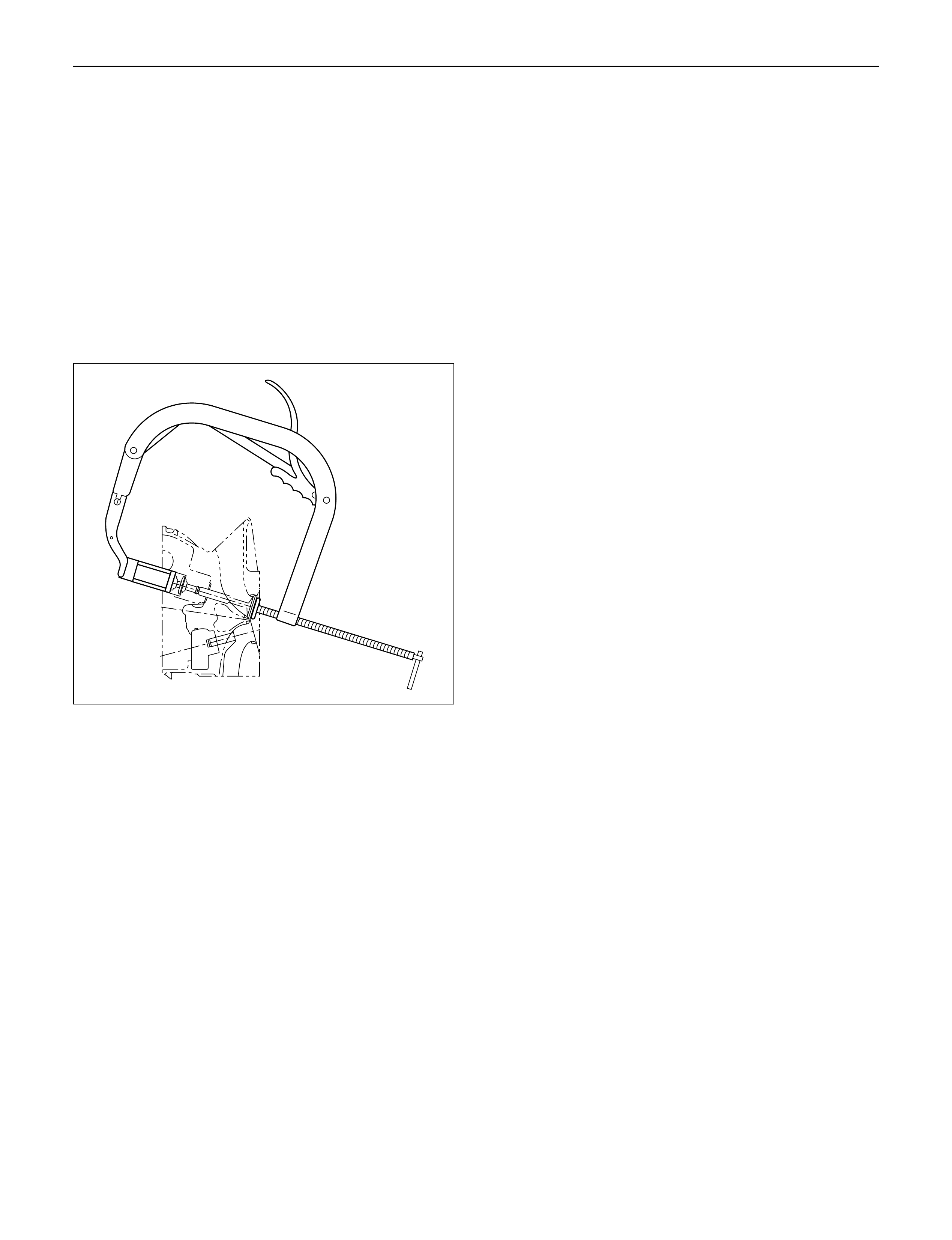
Valve Seat Insert Replacement
Valve Seat Insert Removal
1. Arc weld the entire inside circumference of the
valve seat insert.
2. Allow the valve seat insert to cool for a few minutes.
This will invite contraction and make removal of the
valve seat insert easier.
3. Use a screwdriver to pry the valve seat insert free.
Take care not to damage the cylinder head.
4. Carefully remove carbon and other foreign material
from the cylinder head insert bore.
011RW044
014RS015
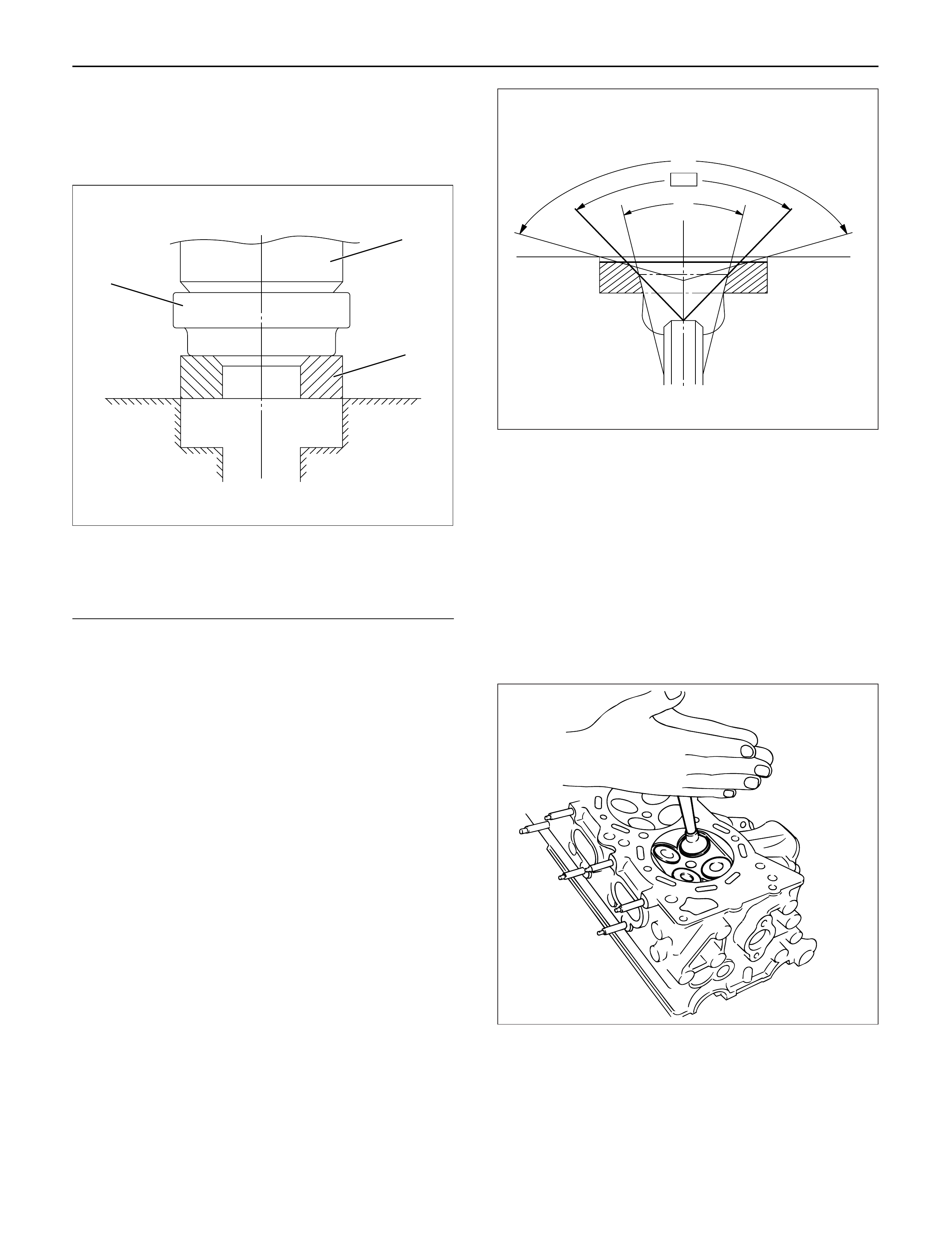
Valve Seat Insert Installation
1. Carefully place the attachment (1) (having a smaller
outside diameter than the valve seat insert) on the
valve seat insert (2).
Legend
(1) Attachment
(2) Valve Seat Insert
(3) Bench Press
NOTE: The smooth side of the attachment must contact
the valve seat insert.
2. Use a bench press (3) to gradually apply pressure
to the attachment and press the valve seat insert
into place.
Note: Do not apply an excessive amount of pressure
with the bench press. Damage to the valve seat insert
will result.
Valve Seat Insert Correction
1. Remove the carbon from the valve seat insert
surface.
2. Use a valve cutter (15°, 45° and 75° blades) to
minimize scratches and other rough areas. This will
bring the contact width back to the standard value.
Remove only the scratches and rough areas. Do
not cut away too much. Take care not to cut away
unblemished areas of the valve seat surface.
Valve Seat Angle: 45°
NOTE: Use an adjustable valve cutter pilot.
Do not allow the valve cutter pilot to wobble inside the
valve guide.
3. Apply abrasive compound to the valve seat insert
surface.
4. Insert the valve into the valve guide.
5. Turn the valve while tapping it to fit the valve seat
insert.
6. Check that the valve contract width is correct.
7. Check that the valve seat insert surface is in
contact with the entire circumference of the valve.
3
2
1
012RW055
150°
90°
30°
012RW056
014RS014
INSTALLATION
1.Valve stem seal
1)Use the special tool to install the stem seal to the
valve guide.
Stem Seal Installer: 5-8840-2033-0
2.Valve spring.
1)Install the lower valve seat spring, valve spring,
then the upper valve spring seat.
2)Use valve spring compressor to compress the
spring then install the split collar.
Valve spring compressor: 5-8840-2441-0
NOTE: Make sure the split collar installs completely.
3.Install cylinder head assembly.
Refer to “Cylinder Head” in this manual.
4.Install the camshaft carrier with camshaft.
Refer to “Camshaft” in this manual.
5.Install oil rail assembly.
Refer to “Oil rail and injector” in this manual.
6.Install injector assembly.
Refer to “Oil rail and injector” in this manual.
7.Install the injector harness assembly.
Refer to “Injector” in this manual.
8.Reconnect harness connecter to oil pressure
sensor and oil temperature sensor on the oil rail.
9.Reconnect Injector harness connecter to injector.
Refer to “Injector” in this manual.
10.Install cylinder head cover with gasket.
Refer to “Cylinder Head Cover” in this manual.
11.Install glow plug with specified torque.
Torque: 15 N·m (1.5 kg·m / 11 lb ft)
12.Install the intake manifold assembly.
Refer to “Intake Manifold” in this manual.
13.Install the fuel pipe.
14.Install the water pipe between the cylinder head
and water pump.
Torque: 20 N·m (2.0 k·m / 14 lb ft)
15.Install the front plate.
16.Install the camshaft pulley.
Refer to “Timing Gear” in this manual.
17.Install timing belt and set the tensioner.
Refer to “Timing Belt” in this manual.
18.Install CMPsensor bracket.
Torque: 20 N·m (2.0 kg·m / 14 lb ft)
19.Install timing belt cover.
Torque: 9 N·m (0.9 kg·m / 78 lb in)
20.Fill the oil rail with engine oil then immediately
install the high pressure oil pipe with the specified
torque.
Torque: 78 N·m (8.0 kg·m / 58 lb ft)
21.Install the noise insulator cover.
22.Reconnect hose between thermostat and radiator.
23.Install turbocharger assembly.
Refer to “Turbocharger” in this manual.
24.Install water hose and oil pipe for turbocharger.
Refer to “Turbocharger” in this manual.
25.Install the valve assembly and install heat protector.
26.Install generator and set the fan belts.
27.Install A/C compressor bracket, compressor
assembly and set drive belt.
28.Reconnect harness connector around cylinder
head.
29.Reconnect vacuum hose to EGR valve.
30.Reconnect PCV hose.
31.Install oil level gauge guide assembly.
32.Install intercooler assembly.
Refer to “Intercooler” in this manual.
33. Install the air duct assembly.
34. Fill engine coolant.
35. Connect battery ground cable.
014RW042
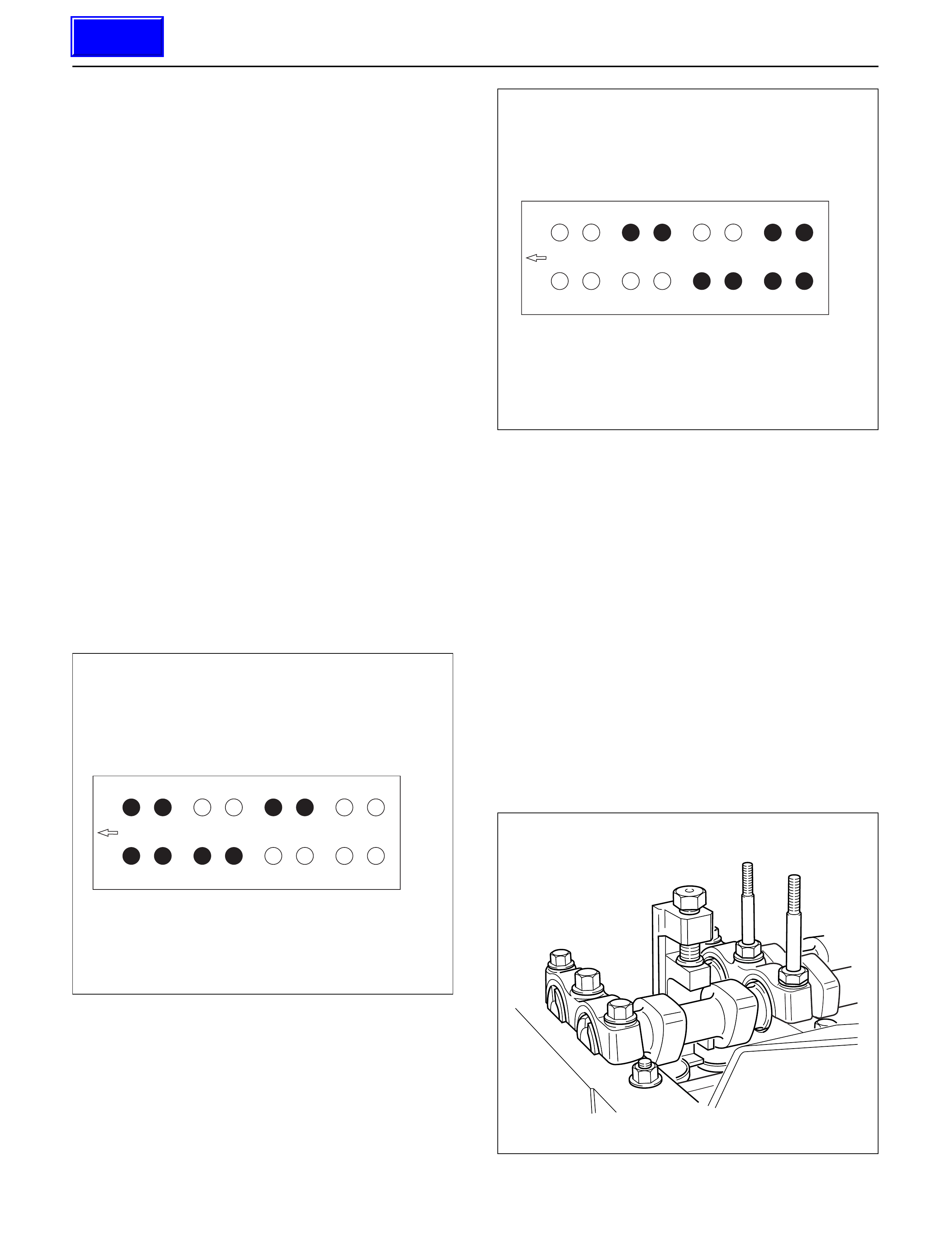
VALVE CLEARANCE ADJUSTMENT
NOTE:
1.Valve clearance should be inspected and adjusted
while the engine is cool.
2.The tightening of the camshaft bearing cap and
camshaft carrier assembly should be checked
before inspecting and adjusting valve clearance.
INSPECTION
1.Remove cylinder head noise insulator cover and
cylinder head cover.
Refer to “Cylinder Head” in this manual.
2. Disconnect all harness connecters of the injector
and remove harness assembly.
3. Drain oil from oil rail assembly.
4. Remove injector clamp nuts and fixing bolts to take
out injector assembly.
5. Loosen oil rail bolts, remove oil rail assembly.
6. Set cylinder No.1 to the TDC at the compression
stroke. Make sure that there is play in cylinder No.1
tappets on inlet and exhaust sides and that there is
no play in cylinder No.4 tappets.
7. Measure valve clearance at No.1 TDC (Refer to the
black circles indicated in the illustration).
Standard Valve clearance:
Intake valve: 0.15 mm (0.0059 in) ± 0.05 mm (0.0020 in)
Exhaust valve: 0.25 mm (0.0098 in) ± 0.05 mm (0.0020 in)
8. Turn the crankshaft one turn to set No.4 cylinder
TDC at the compression stroke.
9. Measure valve clearance at No.4 TDC (Refer to the
black circles indicated in the illustration).
Standard Valve clearance:
Intake valve: 0.15 mm (0.0059 in) ± 0.05 mm (0.0020 in)
Exhaust valve: 0.25 mm (0.0098 in) ± 0.05 mm (0.0020 in)
10. If measured value is outside standard value,
readjust the valve clearance.
ADJUSTMENT
For valve clearance adjustment, follow the procedure
given below.
1. Set cylinder No.1 or No.4 to the TDC at the
compression stroke.
Set the valve clearance adjusting tool on the tappet
requiring adjustment.
After making sure of the correct setting of the
special tool, depress the tappet by turning the bolt.
Valve Clearance Adjusting Tool: 5-8840-2590-0
NOTE: Before depressing the tappet, set the tappet
notch in the direction where adjuster can be easily
taken out.
2. Take out the adjuster using a small screw driver and
finger magnet.
No.1
Ft
No.2
No.1 TDC
No.3 No.4
EXH
IN
011RW045
No.1
Ft
No.2
No.4 TDC
No.3 No.4
EXH
IN
011RW046
014RW150
Techline

3.Determine the thickness of the adjuster as follows.
1)Measure the thickness of the removed adjuster
with a micrometer.
2)Calculate the thickness of a new adjuster.
Calculation
TA:Thickness of new adjuster
M: Valve clearance measurement.
TO:Thickness of the removed adjuster
For intake side:TA=TO+(M–0.15) mm
For exhaust side:TA=TO+(M–0.25) mm
Select a new adjuster whose thickness is as
close to the estimated value as possible.
4.Install oil rail and tighten it temporarily.
5.Install injector assembly.
NOTE:
1)Do not forget to insert the O-ring between injector
and oil rail.
2)Install the injector to the same position as before
removal.
6.Install the injector fixing bolts and temporarily
tighten.
7.Install the injector clamp and tighten temporarily.
8.Tighten injector fixing bolts to the specified torque.
Torque: 6.5 N·m (0.7 kg·m / 61 lb in)
9.Tighten injector clamp nut to the specified torque
with special method.
Torque: 30 N·m (3.1 kg·m /22 lb ft) then loosen one
turn and tighten again to specified torque.
Torque: 25 N·m (2.5 kg·m / 18 lb ft)
10. Tighten oil rail to the specified torque.
Torque: 20 N·m (2.0 kg·m / 14 lb ft)
11.Install injector harness and reconnect connector.
12.Install cylinder head cover.
Refer to ”Cylinder Head” in this manual.
13.Fill with about 300cc of engine oil at the high
pressure oil pipe installation port on the oil rail using
an oil filler.
If assembled without filling the oil rail with oil, the
time for engine starting will be longer.
14.Immediately install high pressure oil pipe to tighten
with specified torque.
Torque: 78 N·m (8.0 kg·m / 58 lb ft)
15.Install cylinder head noise insulator cover.
Refer to “Cylinder Head” in this manual.
Techline
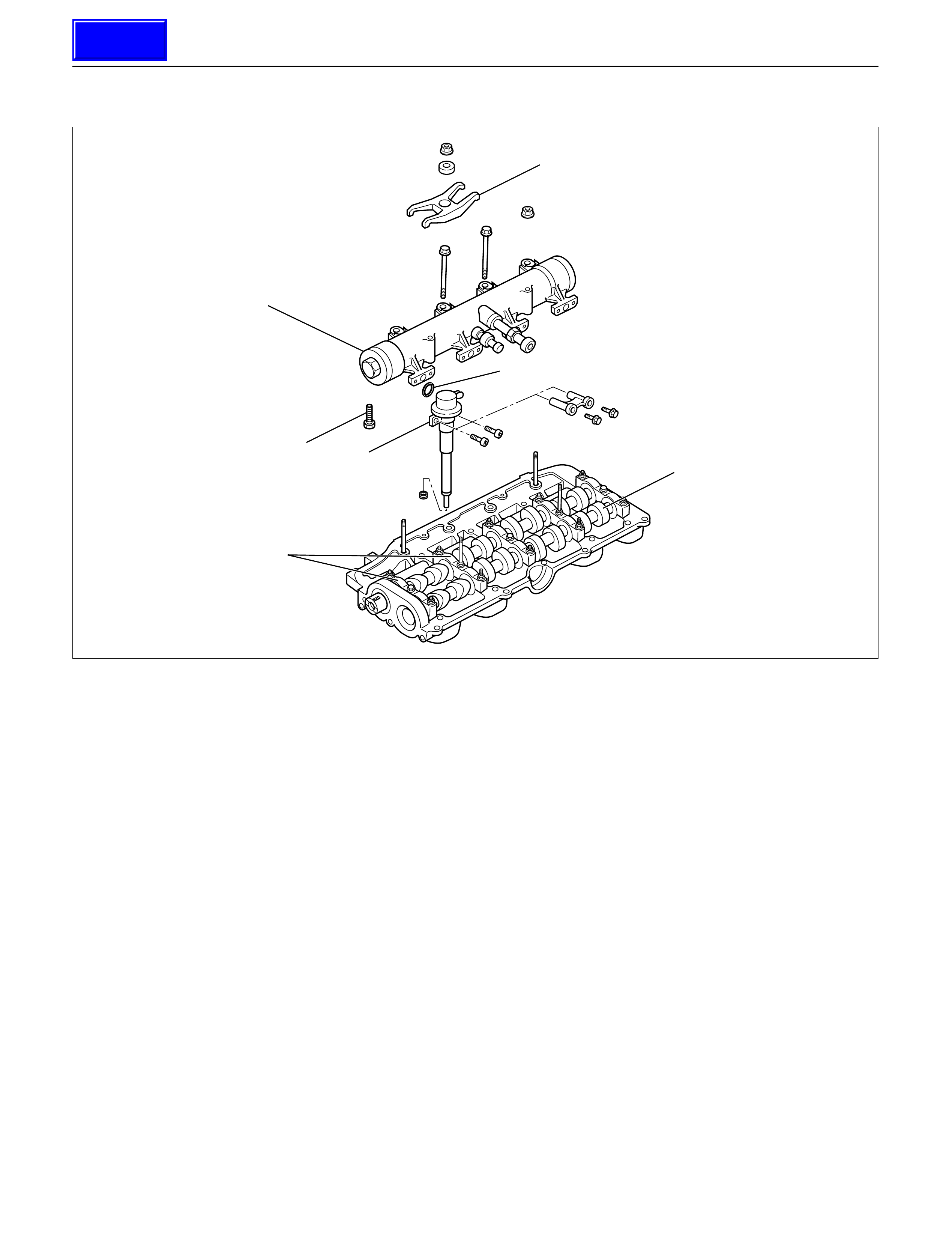
OILRAILAND INJECTOR
REMOVAL
Prior to removal, be sure to confirm and record the
group code of the injector installed using Tech2.
1.Disconnect battery ground cable.
2.Remove air cleaner cover and air duct.
3.Remove intercooler.
Refer to “Intercooler” in this manual.
4.Remove PCV hose and pipe.5. Remove cylinder head noise insulator cover.
6.Remove high pressure oil pipe.
CAUTION:
1) Sleeve nut should be loosened with cloth tied
around it to prevent oil from spurting due to the
remaining pressure.
2) The high pressure pipe should be disconnected
with a cloth tied around the intake manifold
glow plug to prevent oil from flowing out of the
oil rail.
7. Loosen eye bolt of fuel pipe at fuel pump side.
NOTE: Cloth should be put around the loosened eye
bolt to prevent fuel from flowing out.
8. Remove fuel return hose at chassis side.
9. Remove PCV hose to cylinder head cover.
10. Remove cylinder head cover.
11. Drain the oil from oil rail assembly.
12. Record the identification marking of injector for
each cylinder which is indicated on the upper
portion of injector.
There are nine kinds of identification marking
available, one alphabet letter and one numeral
letter.
In case three kinds of markings are given, one
alphabet letter (sometimes printed) and one
numeral letter, top priority is given to the one
alphabet letter and one numeral letter.
1
6
2
7
3
5
4
With
spacer type
Without
spacer type
012R200005
Legend
(1) Injector Clamp
(2) Injector Assembly
(3) Oil Rail Assembly
(4) Camshaft Bracket
(5) Camshaft
(6) O-Ring
(7) Drain Plug
Techline
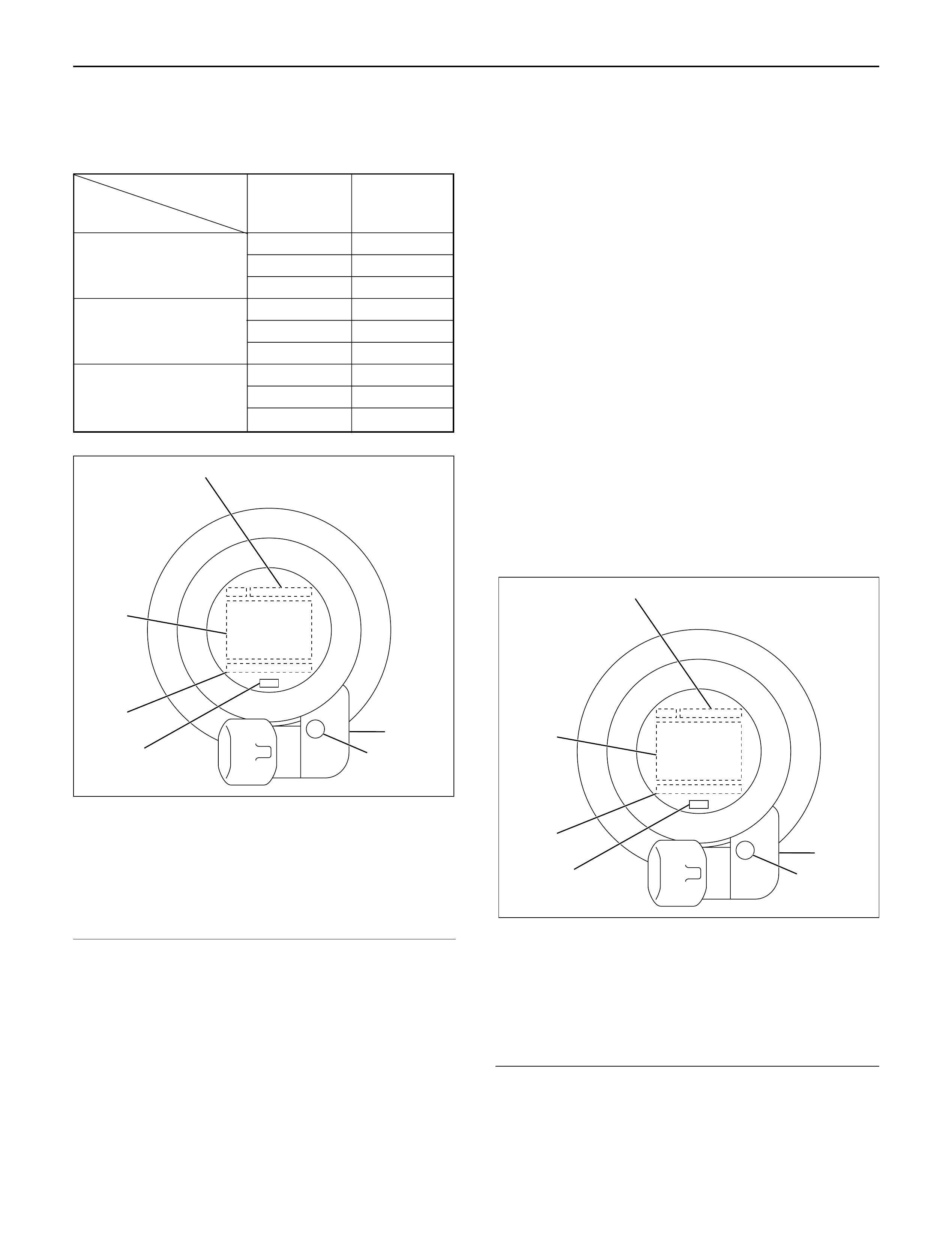
(For example)
If you find identification marking “A”, “RA” and “2”
on the injector, you can use injector grade “A”. (The
“RA” is sometimes printed, but can be ignored)
Legend
(1)Part Number
(2)Two Alphabet Letter
(3)Serial Number
(4)Bar Code
(5)One Alphabet Letter
(6)One Numeral Letter
13.Remove harness connector from each injector.
14.Loosen nuts and bolts for oil rail.
15.Remove injector fixing bolts.
16.Remove injector clamp.
17.Remove injector assembly.
NOTE: Do not drop O-ring
INSTALLATION
1.Install oil rail, tighten temporarily
2.Install injector assembly.
NOTE: Do not forget to install O-ring between injector
and oil rail.
3.Apply oil and install injector fixing bolts, tighten
temporarily.
4.Apply oil and install injector clamp, tighten nut
temporarily.
5.Tighten injector bolts to the specified torque.
Torque: 7 N·m (0.7 kg·m / 61 lb in)
6.Tighten injector clamp nut to the specified torque
with special method.
Torque: 30 N·m (3.1 kg·m / 22 lb ft) then loose a
time again tighten as following torque.
Torque: 25 N·m (2.5 kg·m / 18 lb ft)
7.Tighten oil rail to the specified torque.
Torque: 20 N·m (2.0 kg·m / 14 lb ft)
8.Install injector harness assembly, reconnect
harness connecter to injector.
9.Record the identification marking of injector for
each cylinder that is indicated on the upper portion
of injector.
Legend
(1)Part Number
(2)Two Alphabet Letter
(3)Serial Number
(4)Bar Code
(5)One Alphabet Letter
(6)One Numeral Letter
10.Install cylinder head assembly.
Refer to “Cylinder Head” in this manual.
11. Fill with about 300cc of engine oil from the high
pressure oil pipe at the high pressure oil pipe
installation port on the oil rail using an oil filler.
If assembled without filling the oil rail with oil, the
1
4
3
2
6
5
055RW021-1
1
4
3
2
6
5
055RW021-1
Identification One Alphabet One Numeral
Marking Letter Letter
Grade A1
AA2
A3
B1
BB2
B3
C1
CC2
C3

time for engine starting will be longer.
12.Immediately install high pressure oil pipe and
tighten to specified torque.
Torque: 78 N·m (8.0 kg·m / 58 lb ft)
13.Install cylinder head noise insulator cover.
Refer to “Cylinder Head” in this manual.
14.Install intercooler assembly.
Refer to “Intercooler” in this manual.
15.Install air cleaner cover and air duct.
16.Use TECH2 to rewrite injector data to ECM.
For rewriting method refer to section “Data
Programming in Case of ECM Change” of 6E 4JX1
engine driveability and emissions in this manual.
NOTE:
1) On completion of servicing, bleed air from the
engine inside fuel passage by means of the priming
pump. (The priming pump should be operated more
times than in the case of conventional engines.)
2) As air is in the oil rail, it takes more time to start the
engine. Rough idling may occur while the air is
being bled completely after starting the engine, but
it does not indicate trouble.
The air will be bled and normal engine status will be
reached while the vehicle is driven for about 5 km
or engine is operated for about 5 minutes at 1500 to
2000 rpm.
3) The injector spare part will be provided for group
number B1, B2 and B3 only.
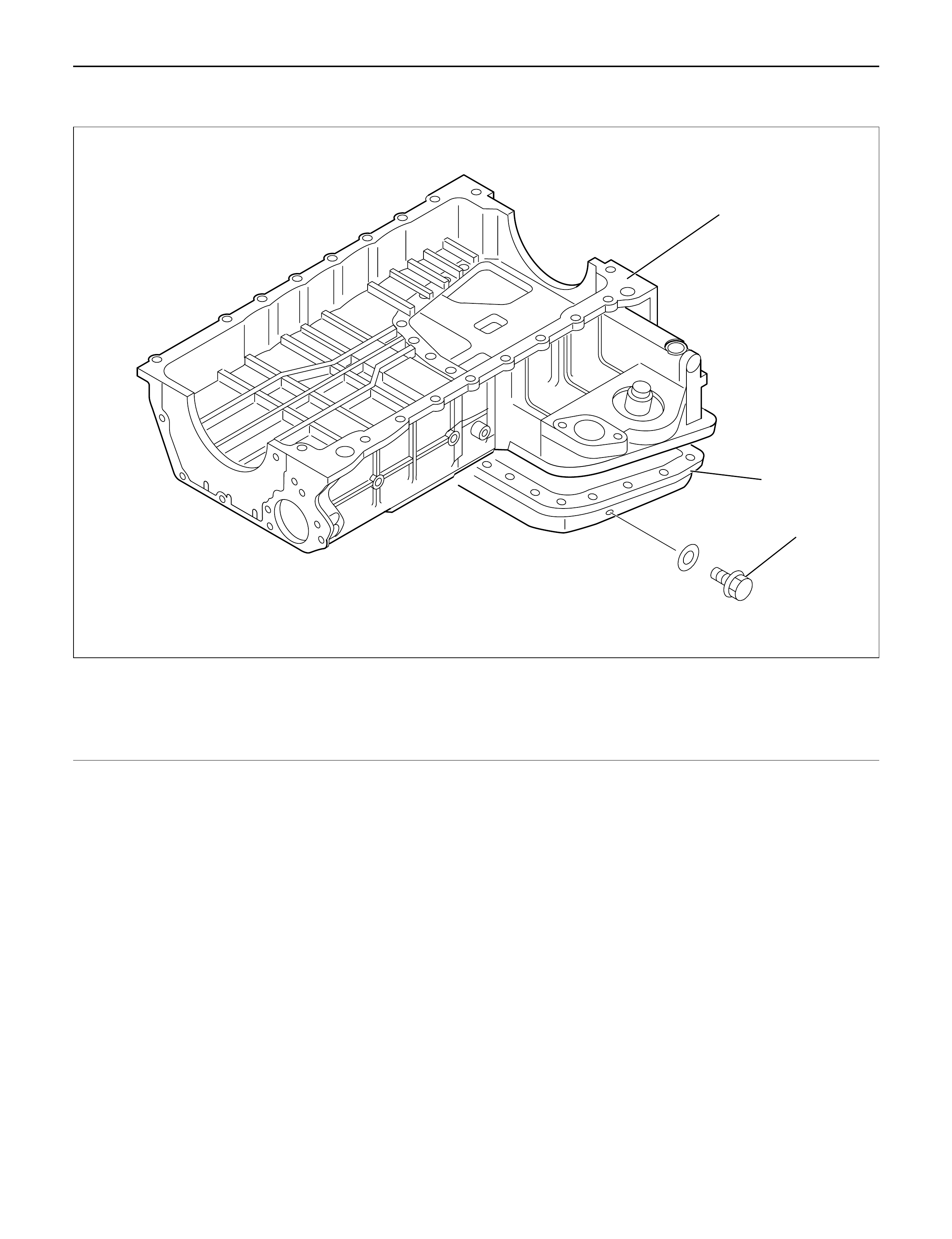
CRANK CASE
REMOVAL
1.Drain engine oil.
2.Remove transmission assembly.
3.Remove crankshaft damper pulley.
4.Remove timing belt cover, timing belt, pulley and
front plate.
5.Remove timing gear case cover.
6.Remove timing gears.
NOTE: Do not forget to set lock bolt for idle gear Aand
lock pin for idle gear C.
7.Remove timing gear case.
8.Remove oil level gauge guide assembly.
9.Remove flywheel assembly.
CAUTION:
1) The flywheel heavy; be careful not to drop it.
2) Be careful no to let it slip because the hexagon
of the bolt is thin.
10. Remove rear plate (for A/T) or flywheel housing (for
MT).
11. Remove retainer.
NOTE:
1) Be careful not to damage the oil seal; it can be
reused.
2) Inspect installation portion for distortion and flow on
the slinger; also inspect for flow on the oil seal lip.
3) If there is some flow oil seal/slinger, replace a set.
12. Remove bolts from thrust plate of balance shaft LH
then remove balance shaft.
13. Loosen crank case fixing bolts.
14. Use seal cutter to take off the liquid gasket.
Seal cutter: 5-8840-2153-0
15. Remove crank case assembly.
CAUTION:
Do not give shock to crank case for prevention take
off applied vibration insulation material on the
crank case.
1
2
3
012RW029
Legend
(1) Crank Case
(2) Oil Pan
(3) Drain Plug
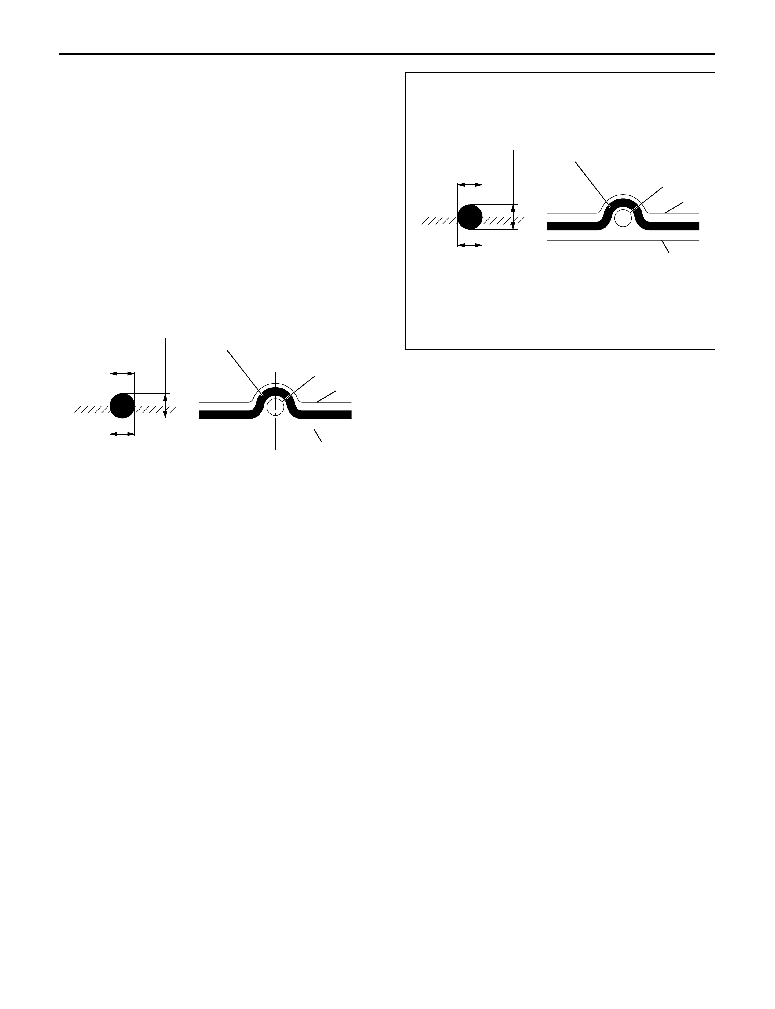
INSTALLATION
1.Install relief valve (if it was removed).
Torque: 30 N·m (3.1 kg·m / 22 lb ft)
2.Apply oil and insert O-ring to strainer, install strainer
and tighten to specified torque.
Torque: 20 N·m (2.0 kg·m / 14 lb ft)
3.Apply liquid gasket (TB1207B or equivalent) to
surface of oil pan and tighten bolt to the specified
torque.
Torque: 22 N·m (2.2 kg·m / 16 lb ft)
4.Apply engine oil to the balance shaft (left) and insert
it into crank case.
NOTE:
•Do not damage bearing when inserting the balance
shaft.
•Make sure it rotates smoothly.
5.Tighten thrust plate of balance shaft LH.
Torque: 25 N·m (2.5 kg·m / 18 lb ft)
6.Set O-ring port of oil gallery on the cylinder block.
7.Apply liquid gasket (TB1207C or equivalent) to
crankcase fixing surface then tighten bolts to the
specified torque.
Torque: 24 N·m (2.4 kg·m / 17 lb ft)
NOTE: Make sure there is no oil, dust or scratches on
the surface coated with liquid gasket and mount within
five minutes of gasket application.
8.Install retainer with oil seal.
9.Install rear plate (A/T) or flywheel housing (MT),
tighten bolt to the specified torque.
Torque: 97 N·m 9.9 kg·m / 72 lb ft)
10.Install flywheel assembly with applied engine oil to
the bolt, tighten the bolt using angular tightening
method.
1st step: 59 N·m (6.0 kg·m / 43 lb ft)
2nd step: 60°to 90°
3rd step: 60°to 90°
11.Install oil level gauge guide assembly.
12.Install timing gear case.
Torque: 20 N·m (2.0 kg·m / 14 lb ft)
13.Install timing gears
Refer to “Timing Gear” in this manual.
14.Remove lock bolt from idle gear Aand remove lock
pin from idle gear C.
15.Install timing gear case cover.
Torque: 20 N·m (2.0 kg·m / 14 lb ft)
16.Install oil pump pulley.
Torque: 10 N·m (1.0 kg·m / 87 lb in)
17.Install camshaft pulley tighten bolt with angular
tightening method.
Torque:
1st step: 40 N·m (4.1 kg·m / 30 lb ft)
2nd step: 60°to 90°
18.Install timing belt and belt tensioner.
Refer to “Timing Gear” in this manual.
19. Install crankshaft damper pulley.
Torque: 216 N·m (22 kg·m / 159 lb ft)
20. Fill engine oil.
2
2~2.5mm
2~2.5mm
Apply liquid gasket around inside
of the bolt hole
Bolt hole
Inside
Outside
F06HX00001
2
2~2.5mm
2~2.5mm
Apply liquid gasket around inside
of the bolt hole
Bolt hole
Inside
Outside
F06HX00001
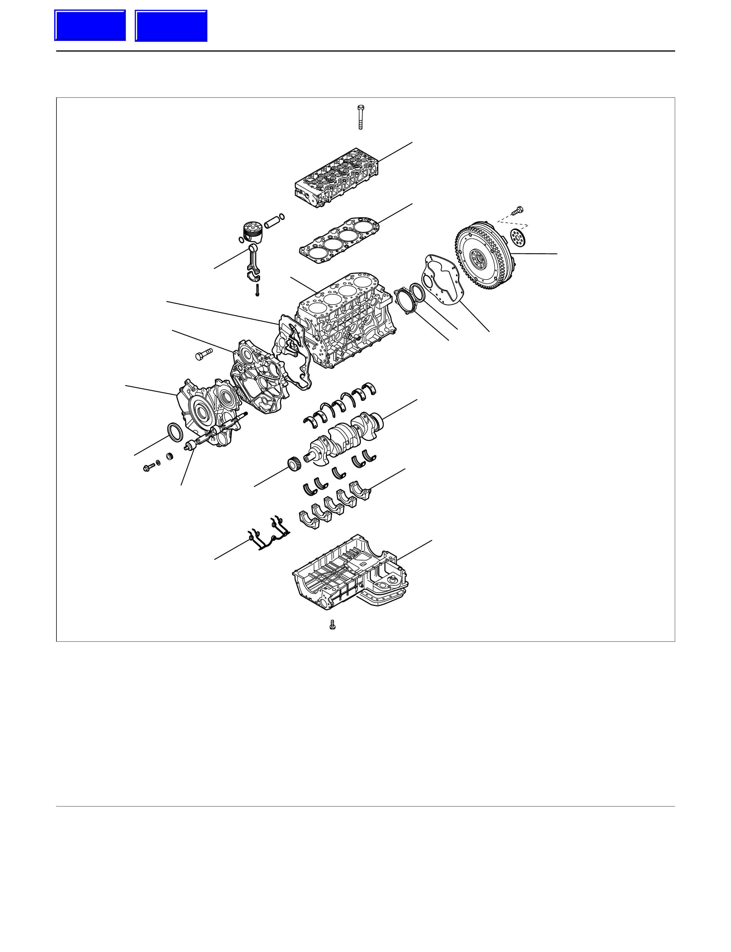
CRANKSHAFT
1
15
14
13
8
11 16
17
10
9
7
2
12
3
4
65
18
012RW023
Legend
(1) Cylinder Head
(2) Cylinder Head Gasket
(3) Flywheel
(4) Cylinder Block Rear Plate (for A/T) or Flywheel
Housing (for M/T)
(5) Crankshaft Rear Oil Seal
(6) Retainer
(7) Timing Gear Case
(8) Crankshaft Front Oil Seal
(9) Timing Gear Case
(10) Gasket
(11) Balance Shaft
(12) Crank Case
(13) Piston Cooling Oil Pipe
(14) Main Bearing Cap
(15) Crankshaft
(16) Crankshaft Timing Gear
(17) Piston and Connecting Rod Assembly
(18) Cylinder Block
Techline
Techline
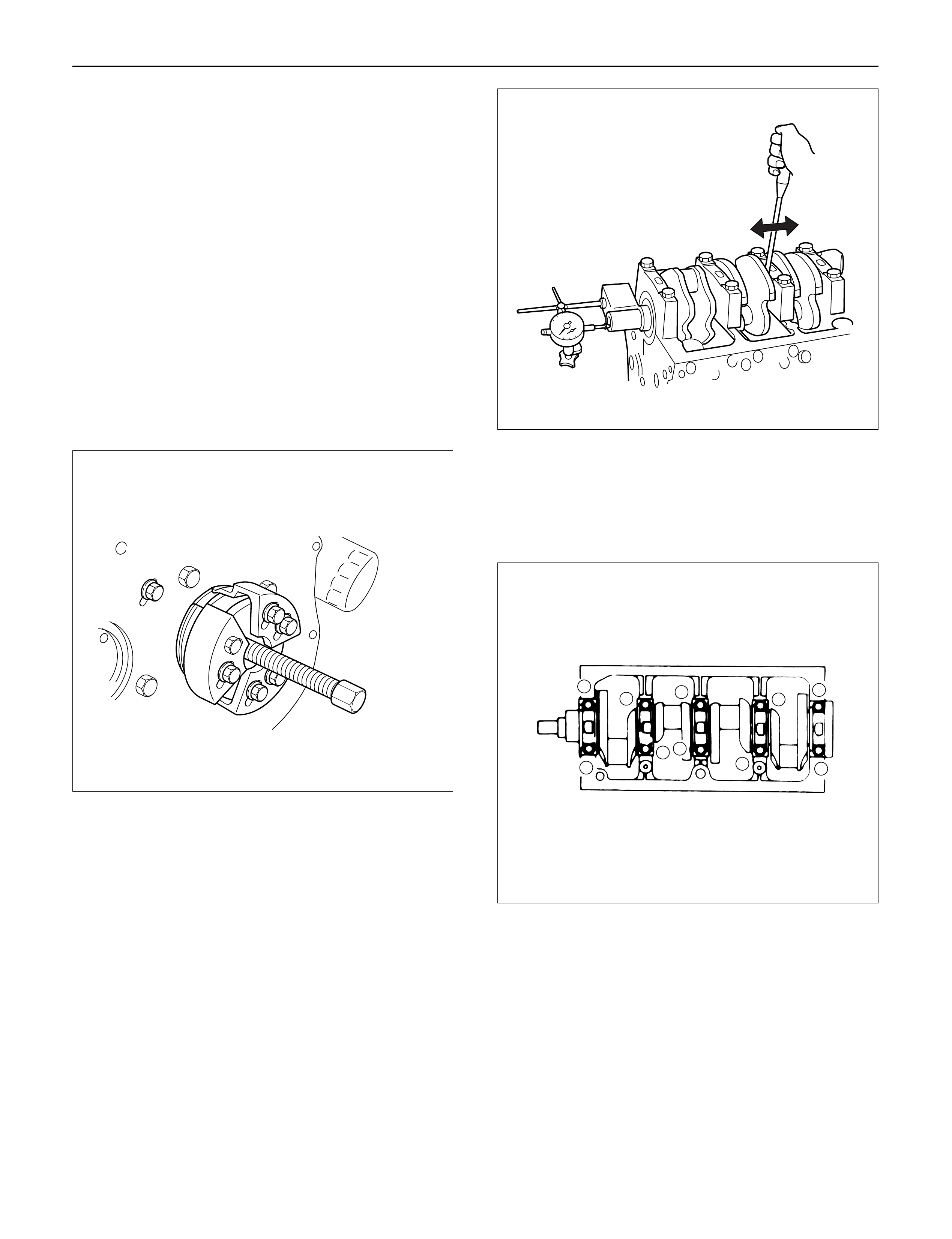
DISASSEMBLY
1.Cylinder Head
1)Refer to “Cylinder head” in this manual.
2. Crankshaft Front Oil Seal
1) Use a plastic hammer and a screwdriver to tap
around the oil seal to free it from the gear case
cover.
Take care not to damage the oil seal fitting
surfaces.
3. Crankshaft Timing Gear
4. Timing Gear Case
5. Flywheel
6. Cylinder Block Rear Plate
7. Crankshaft Rear Oil Seal
1) Use special tool to remove the crankshaft rear
oil seal.
Oil Seal Remover: 5-8840-2360-0
8. Crank Case
9. Piston Cooling Oil Pipe
10. Piston and Connecting Rod Assembly
11. Main Bearing Cap Assembly
12. Crankshaft
INSPECTION AND REPAIR
Make the necessary adjustments, repairs, and part
replacements if excessive wear or damage is
discovered during inspection.
1. Crankshaft Thrust clearance
Set the dial indicator as shown in the illustration and
measure the crankshaft thrust clearance.
If the thrust clearance exceeds the specified limit,
replace the thrust bearing as a set.
Standard : 0.04 – 0.20 mm (0.0016 – 0.0079 in)
Limit: 0.30 mm (0.0118 in)
2. Main bearing clearance
1) Remove the main bearing caps in the sequence
shown in the illustration.
Arrange the removed main bearing caps in the
cylinder number order.
2) Remove the crankshaft. Remove the main
bearings.
3) Clean the upper and lower bearings as well as
the crankshaft main journal.
4) Check the bearings for damage or excessive
wear.
The bearings must be replaced as a set if
damage or excessive wear is discovered during
inspection.
5) Set the upper bearings and the thrust washers
to their original positions. Carefully install the
crankshaft.
6) Set the lower bearings to the bearing cap
original position.
015LV002
012RW063
3710 62
51
9
8
4
012RW026
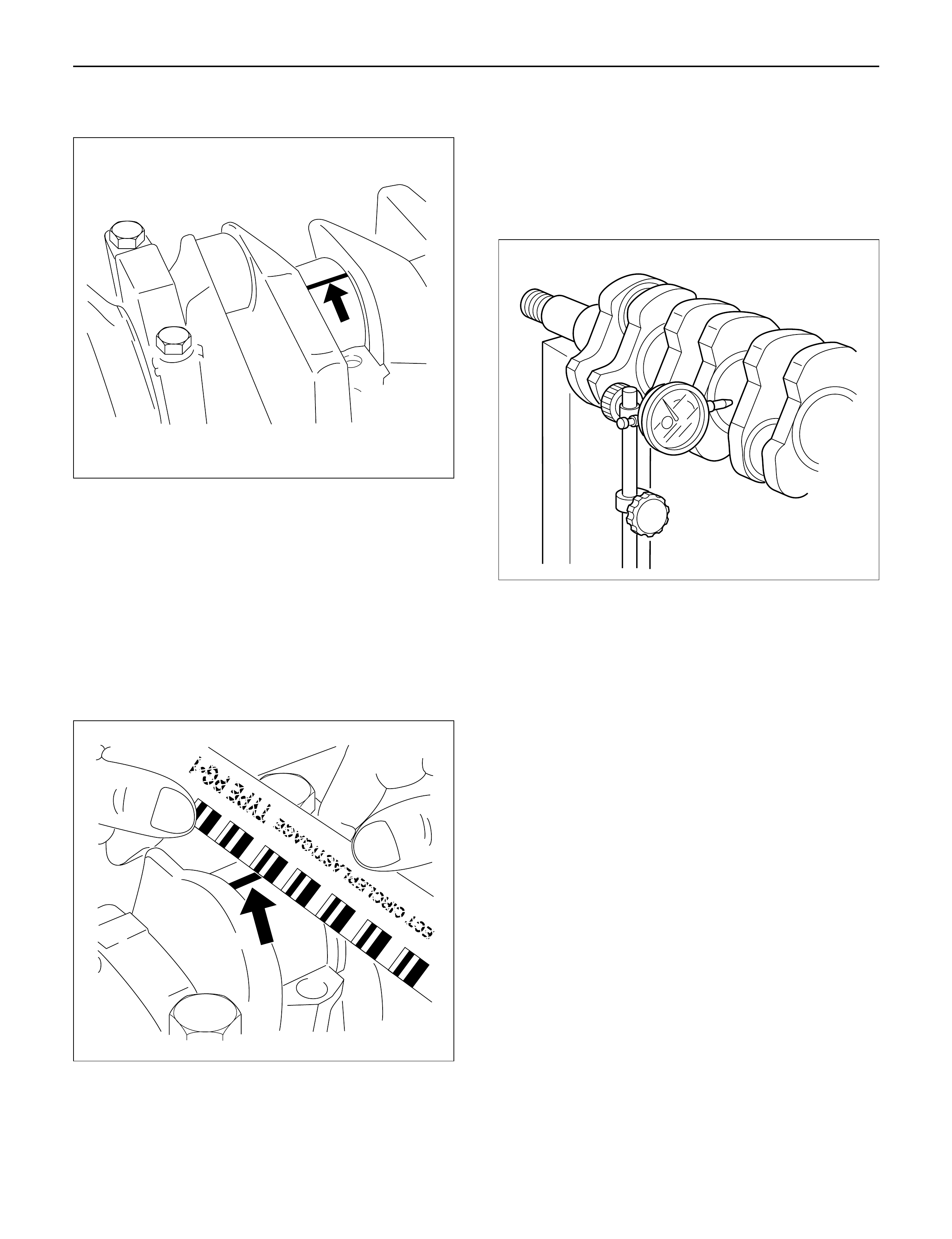
7) Apply plastigage to the crankshaft journal unit as
shown in the illustration.
8) Install the main bearing caps. Apply engine oil to
the bolt threads and the seats. Tighten the bolts
to the specified torque.
Torque: 167 N·m (17 kg·m/123 lb ft)
NOTE: Do not allow the crankshaft to rotate.
9) Remove the main bearing caps.
10) Measure the plastigage width and determine the
oil clearance. If the oil clearance exceeds the
specified limit, replace the main bearings as a
set and/or replace the crankshaft.
11) Clean the plastigage from the bearings and the
crankshaft.
Remove the crankshaft and the bearings.
Standard: 0.031 – 0.063 mm (0.0012 – 0.0025 in)
Limit: 0.11 mm (0.0043 in)
3. Run-out
1) Carefully set the crankshaft on the V-blocks.
Slowly rotate the crankshaft and measure the
runout. If the crankshaft runout exceeds the
specified limit, the crankshaft must be replaced.
Standard: 0.05 mm (0.0020 in) or less
Limit: 0.08 mm (0.0031 in)
Measure the diameter and the uneven wear of
main journal and crank pin.
If the crankshaft wear exceeds the specified
limit, crankshaft must be replaced.
Main journal diameter
Standard: 69.917 – 69.932 mm (2.7526 – 2.7532 in)
Limit: 69.91 mm (2.7524 in)
Crank pin diameter
Standard: 52.915 – 52.930 mm (2.0833 – 2.0839 in)
Limit: 52.90 mm (2.0827 in)
Uneven wear limit
Standard: 0.05 mm (0.0020 in) or less
Limit: 0.08 mm (0.0031 in)
014RW055
014RW077
012RW068
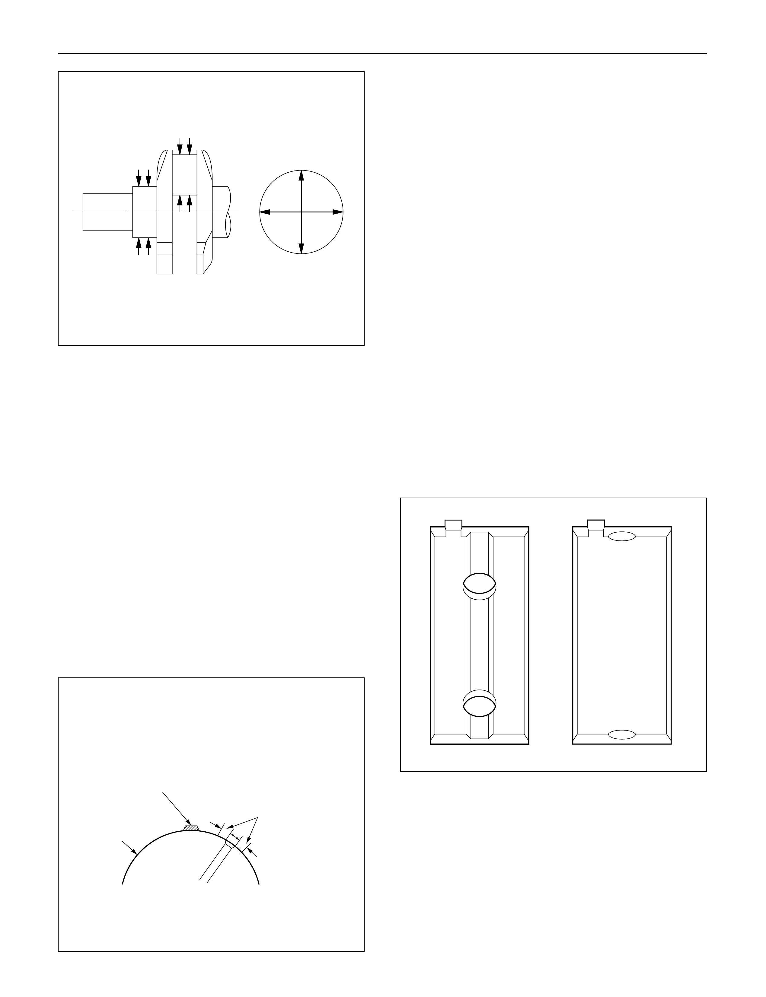
Crankshaft inspection
Inspect the surface of the crankshaft journals and crank
pins for excessive wear and damage.
Inspect the oil seal fitting surfaces for excessive wear
and damage.
Inspect the oil ports for obstructions.
Crankshaft tufftriding inspection
1. Use an organic cleaner to thoroughly clean the
crankshaft. There must be no traces of on the
surfaces to be inspected.
2. Prepare a 5 – 10% solution of ammonium cupric
chloride (dissolved in distilled water).
3. Use a syringe to apply the solution to the surface to
be inspected.
Hold the surface to be inspected perfectly
horizontal to prevent the solution from running.
NOTE: Do not allow the solution to come in contact with
the oil ports and their surrounding area (Approximately
10 mm).
Judgment
1. Wait for thirty or forty seconds.
If there is no discoloration after thirty or forty
seconds, the crankshaft is usable.
If discoloration appears (the surface being tested
will become the color of copper), the crankshaft
must be replaced.
2. Steam clean the crankshaft surface immediately
after completing the test.
NOTE: The ammonium cupric chloride solution is highly
corrosive. Because of this, it is imperative that the
surfaces being tested be cleaned immediately after
completing the test.
CRANKSHAFT BEARING SECTION
When installing new crankshaft bearings, refer to the
selection table below.
Select and install the new crankshaft bearings, paying
close attention to the cylinder body journal hole
diameter grade mark and the crankshaft journal
diameter grade mark.
NOTE: Although all upper journal bearings (cylinder
body side) have oil grooves and holes, all lower
bearings (bearing cap side) have no groove and hole.
Play close attention to the distinction during the
installation procedure.
012RW045
The portion to be tested
must be held horizontally
so as not to let the test
solution flow.
The sliding surface
of the pin
or journal.
Test liquid should
not be applied to
the area around the
oil port.
Approximately
10mm
F06MV020
012RW038

Crankshaft Bearing Bore Grade Mark Position
Crankshaft bearing bore grade marks 1or 2are
stamped on the rear right hand side of the cylinder
body.
Example:
No. 1 Bearing No. 2 Bearing No. 3 Bearing No. 4 Bearing No. 5 Bearing
Housing Housing Housing Housing Housing
Legend
(1) No. 1 Main bearing bore grade
(2) No. 2 Main bearing bore grade
(3) No. 3 Main bearing bore grade
(4) No. 4 Main bearing bore grade
(5) No. 5 Main bearing bore grade
Crankshaft Journal Grade Mark Position
The crankshaft journal grade marks (1 or –) are
stamped on each crankshaft journal wave.
The crankshaft journal and bearing clearance must be
the same for each position after installation of the
crankshaft and the crankshaft bearings.
Legend
(1) Crankshaft journal outside diameter grade
1 2 1 1 2
1
11122
2345
1
2
3
4
5
012RW114
1
015RW078
012RW069

Main Bearing Crankshaft
Bore Diameter mm(in) Main Journal Diameter mm(in) Crankshaft Oil Clearance
Grade Inside Diameter Grade Outside Diameter Bearing mm(in)
1 or - 69.927 – 69.932 4 0.045 – 0.061
(2.7530 – 2.7532) (0.0018 – 0.0024)
1 73.992 – 74.000 2 or - - 69.922 – 69.927 4 0.050 – 0.066
(2.9131 – 2.9134) (2.7528 – 2.7530) (0.0020 – 0.0026)
3 or - - - 69.917 – 69.922 5 0.052 – 0.068
(2.7526 – 2.7528) (0.0020 – 0.0027)
1 or - 69.927 – 69.932 2 0.042 – 0.059
(2.7530 – 2.7532) (0.0017 – 0.0023)
2 73.983 – 73.992 2 or - - 69.922 – 69.927 3 0.044 – 0.061
(2.9127 – 2.9131) (2.7528 – 2.7530) (0.0017 – 0.0024)
3 or - - - 69.917 – 69.922 4 0.046 – 0.063
(2.7526 – 2.7528) (0.0018 – 0.0025)
1 or - 69.927 – 69.932 1 0.037 – 0.053
(2.7530 – 2.7532) (0.0015 – 0.0021)
3 73.975 – 73.983 2 or - - 69.922 – 69.927 2 0.039 – 0.055
(2.9124 – 2.9127) (2.7528 – 2.7530) (0.0015 – 0.0022)
3 or - - - 69.917 – 69.922 2 0.044 – 0.060
(2.7526 – 2.7528) (0.0017 – 0.0024)
REASSEMBLY
1. Crankshaft
1) Install the main bearings to the cylinder body
and the main bearing caps.
2) Be sure that they are positioned correctly.
3) Apply new engine oil to the upper and lower
main bearing faces.
4) Carefully mount the crankshaft.
5) Apply engine oil to the thrust washer.
6) Assemble the thrust washer to the No. 3 bearing
journal. The oil grooves must face the
crankshaft.
7) Install the bearing caps with the bearing cap
head arrow mark facing the front of the engine.
8) Apply engine oil to the main bearing cap bolts.
9) Tighten the main bearing cap bolts to the
specified torque a little at a time in the sequence
shown in the illustration.
Torque: 167 N·m (17.0 kg·m/123 lb ft)
NOTE: Check to see that the crankshaft turns smoothly
by rotating it manually.
012RW047
84159
610
2
3
7
012RW027
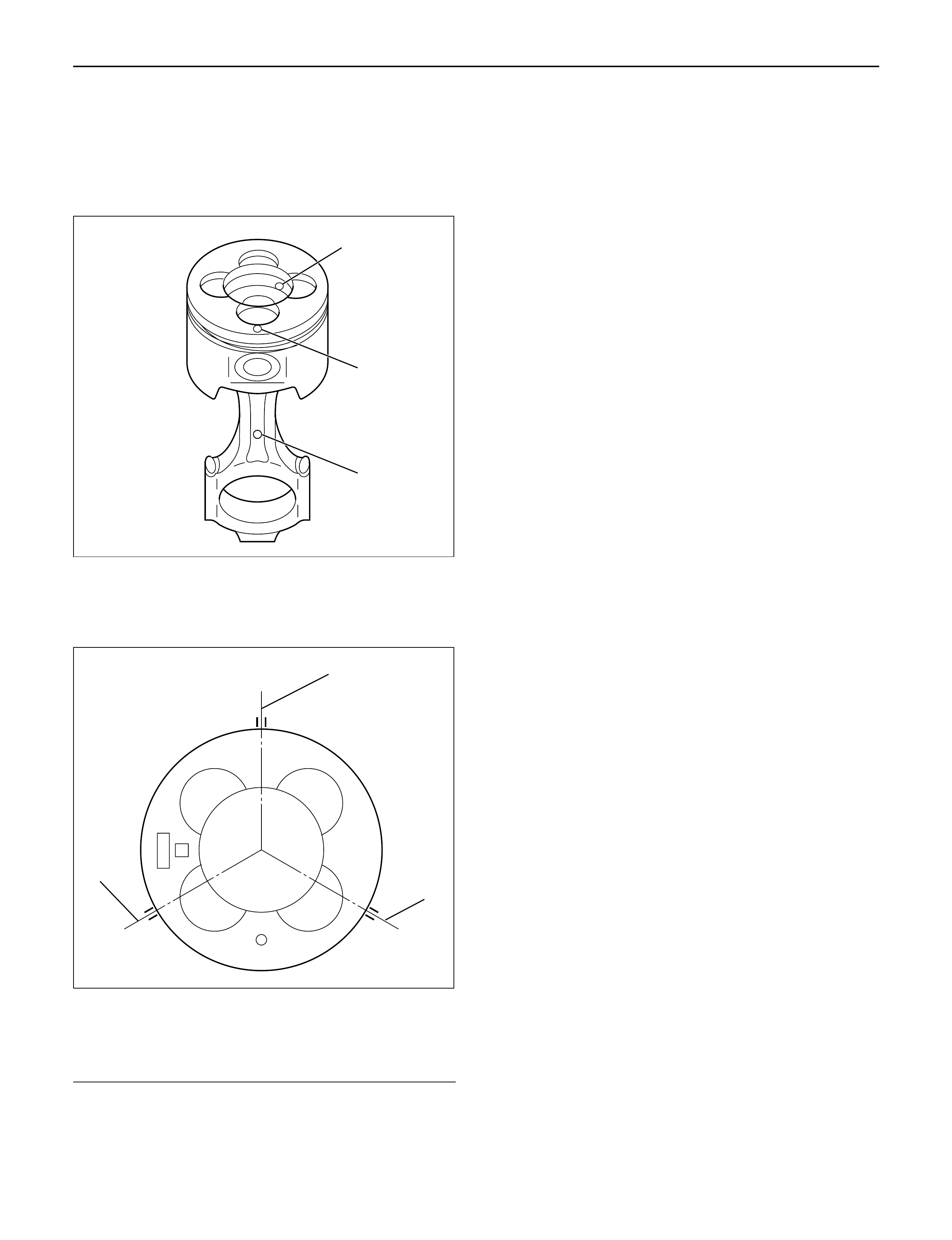
2.Piston and Connecting Rod Assembly
1)Apply engine oil to the cylinder bores, the
connecting rod bearings and the crankshaft pins
and each piston ring and piston.
2)Align the front mark (2) of piston and front mark
(3) of connecting rod then assemble them.
3)The N mark of the piston ring is faced toward the
top, check to see that the piston ring end gap is
correctly positioned.
Legend
(1)1st piston ring end gap
(2)2nd piston ring end gap
(3)Oil ring end gap
4)Insert the piston/connecting rod assemblies into
each cylinder with the piston ring compressor.
The front marks must be facing the front of the
engine.
Piston Ring Compressor: 5-8840-9018-0
5)Match the numbered caps with the numbers on
the connecting rods. Align the punched marks
on the connecting rods and caps.
6)Apply engine oil to the threads and seating faces
of the nuts.
7)Tighten the cap nuts in 2 steps, using angular
tightening method as shown in the following
specifications.
1st step: 29 N·m (3.0 kg·m/22 lb ft)
2nd step: 45°– 60°
After tightening the cap nuts, check to see that
the crankshaft rotates smoothly
3.Piston Cooling Oil Pipe
If the piston cooling oil pipe is forcibly assembled,
the end of the oil jet may bend. It could make it
impossible to supply oil to the piston cooling holes,
which will sometimes cause piston seizure.
Sufficient care should be taken to pipe assembly
work.
1)Tighten the bolt and oil jet plug to the specified
torque.
Torque:
M6: 8 N·m (0.8 kg·m/69 lb in)
M8: 20 N·m (2.0 kg·m/14 lb ft)
Oiling Jet Plug: 30 N·m (3.1 kg·m/22 lb ft)
4.Crank case
1)Refer to “Crank case” in this manual.
5. Apply liquid gasket (TB-1207C or equivalent) to
retainer then install it to rear end of cylinder block
within 5 minutes.
6. Crankshaft Rear Oil Seal
1) Tighten the adapter to the crankshaft rear and
section with 2 bolts.
2) Insert the oil seal into the peripheral section of
the adapter.
NOTE: Apply oil to the oil seal lip.
3) Insert the sleeve into the adapter and tighten it
with a bolt (M12 x 1.75L = 70) until the adapter
hits the sleeve.
4) Remove the adapter and the sleeve.
5) Check the dimension of the oil seal setting from
rear end of crankshaft.
Standard Dimension = 12.5 ± 0.3 mm
Oil Seal Installer: 5-8840-2359-0
2
3
1
015RW051
3
1
2
015RW083

7.Cylinder Block Rear Plate (A/T)
Align the rear plate with the cylinder block dowel
pins.
Tighten the rear plate to the specified torque.
Torque: 97 N·m (9.9 kg·m/72 lb ft)
8.Flywheel housing (M/T)
Align the flywheel housing with the cylinder block
dowel pins.
Tighten the bolt to the specified torque.
Torque: 97 N·m (9.9 kg·m/72 lb ft)
9. Flywheel
1) Thoroughly clean and remove the oil from the
threads of crankshaft and flywheel fixing
surface.
2) Mount the flywheel on the crankshaft and then
install the washer.
3) Align the timing mark, cut out on the flywheel is
at lowest position for M/T model and
identification hole on the boss is highest position
for A/T model when cylinder No. 1 is at the TDC.
For M/T Model
For A/T model
4) Tighten the flywheel bolts in 2 steps using
angular tightening method.
Torque: 1st step 59 N·m (6.0 kg·m/43 lb ft)
Torque: 2nd step 60° – 90°
Torque: 3rd step 60° – 90°
10. Timing Gear Case
1) Cut away the gasket protruding between the
cylinder block and the crank case fitting surfaces
(as shown in the illustration).
12.5 + 0.3
–
012RW067
Timing mark
278
74
015RW121
Timing mark
74
304
015RW120
7
51
3
8
62
4
201RW021
Techline
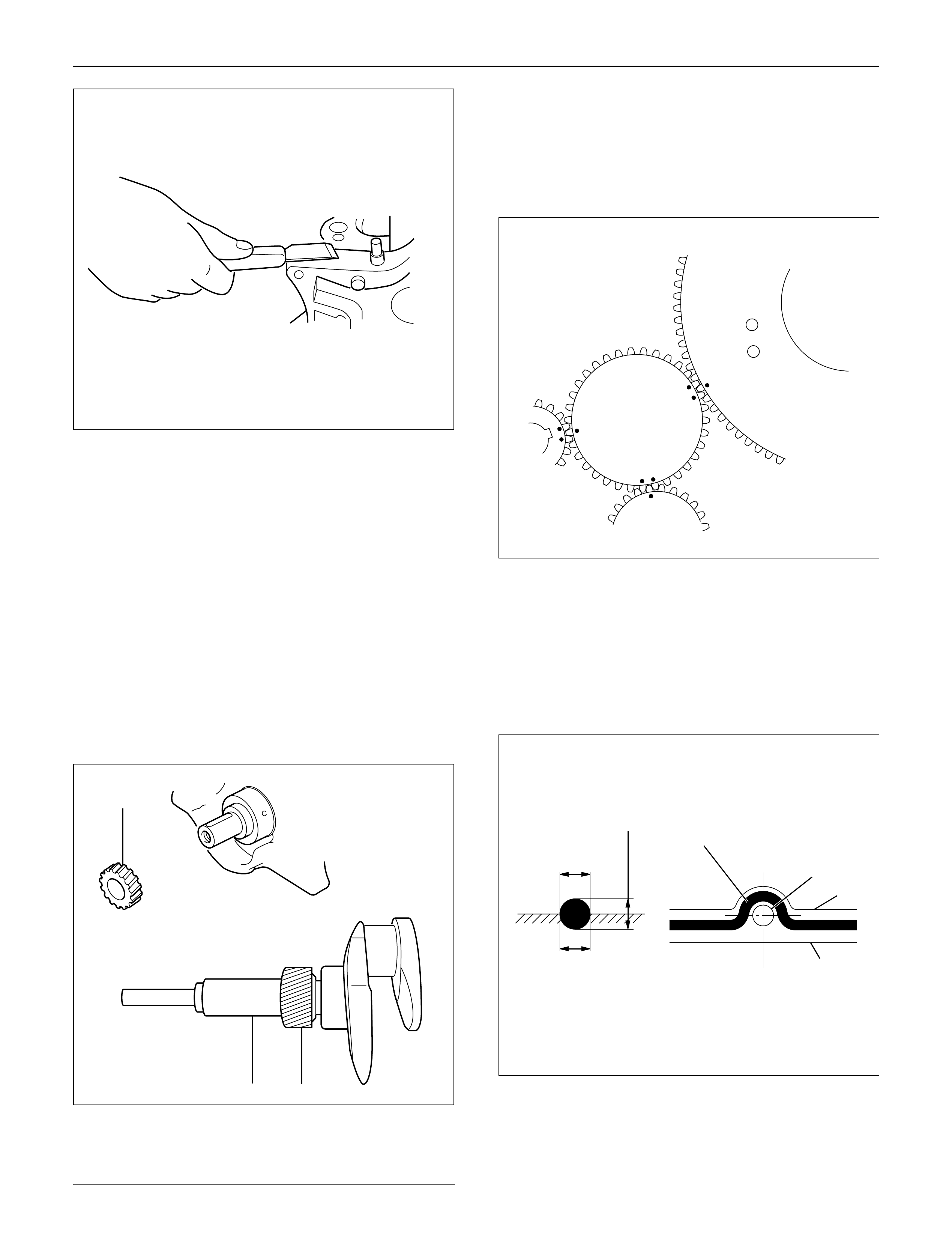
2) Apply liquid gasket (TB1207B or equivalent)
between the cylinder block and the crankcase
fitting surfaces.
3) Install the timing gear case to the cylinder body.
4) Tighten the timing gear case bolt together with
the timing gear case gasket to the specified
torque.
Torque: 20 N·m (2.0 kg·m/14 lb·ft)
11. Crankshaft Gear
1) Set key to crankshaft key groove.
2) The timing mark on the crankshaft gear must be
facing outward.
3) Use the crankshaft gear installer to install the
crankshaft gear.
Crankshaft installer: 9-8522-0021-0
Legend
(1) Crankshaft Gear Installer
(2) Crankshaft Gear
12. Installation of the Timing Gear
1) Align teeth on the scissors gear and lock them
before install timing gear.
2) Align timing marks on each timing gear and
assemble them.
3) Refer to timing gear detail in this manual.
13. Timing Gear Case Cover
1) Remove lock bolt from idle gear A and remove
lock pin from idle gear C.
2) Install oil pump gear oil seal before assembling
timing gear case cover.
3) Clean fitting surface and apply liquid gasket
(TB1207C or equivalent) to fitting surface.
4) Tighten bolts to specified torque.
Torque: 20 N·m (2.0 kg·m/14 lb ft)
12
2
012RW066
2
2~2.5mm
2~2.5mm
Apply liquid gasket around inside
of the bolt hole
Bolt hole
Inside
Outside
F06HX00001
012RW024
012RW064
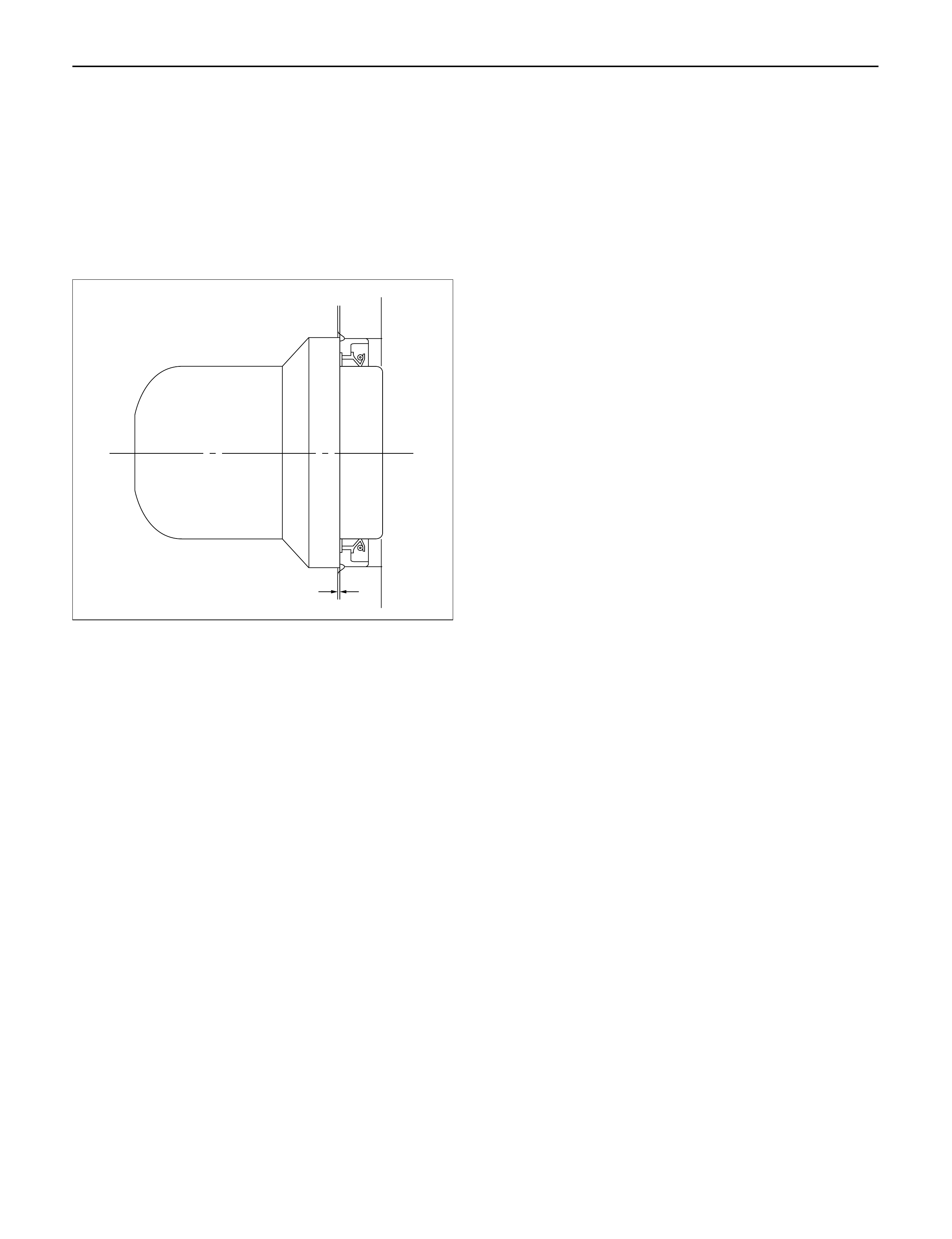
14.Crankshaft Front Oil Seal
1)Set oil seal with special tool.
2)Install front oil seal to timing gear case cover.
Crankshaft Front Oil Seal Installer: 5-8840-2061-0
NOTE: Apply oil to the oil seal lip.
3)Remove special tool and check oil seal position
from front surface of timing gear case.
Oil Seal Position: 0.5 – 2.5 mm (0.0197 –0.0984 in)
15.Cylinder Head
1)Refer to “Cylinder head” in this manual.
015RW074
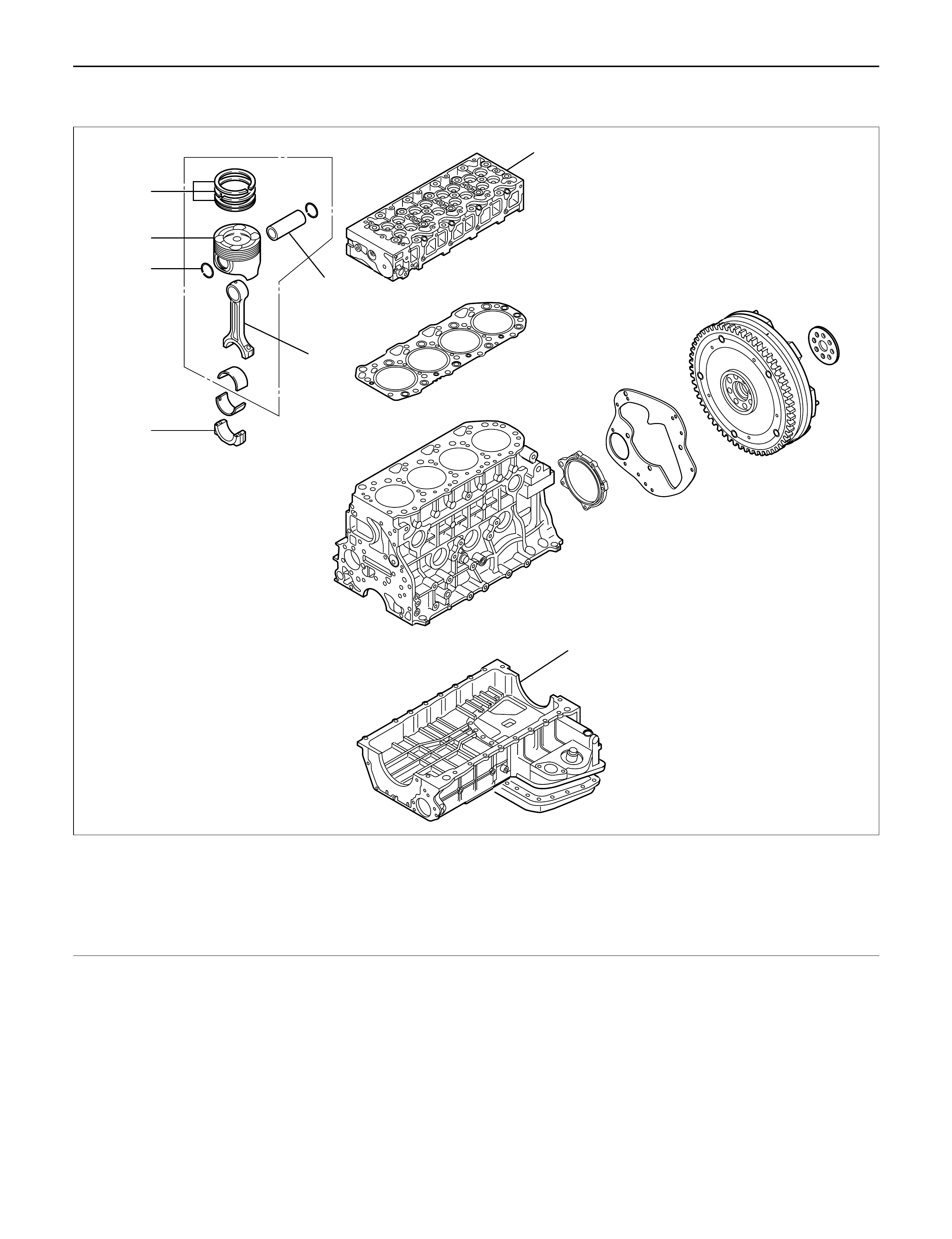
PISTON AND CONNECTING ROD
5
8
7
3
1
2
6
4
012RW061
Legend
(1) Cylinder Head Assembly
(2) Crank Case
(3) Connecting Rod Bearing Cap
(4) Connecting Rod
(5) Piston Ring
(6) Piston Pin
(7) Piston Pin Snap Ring
(8) Piston
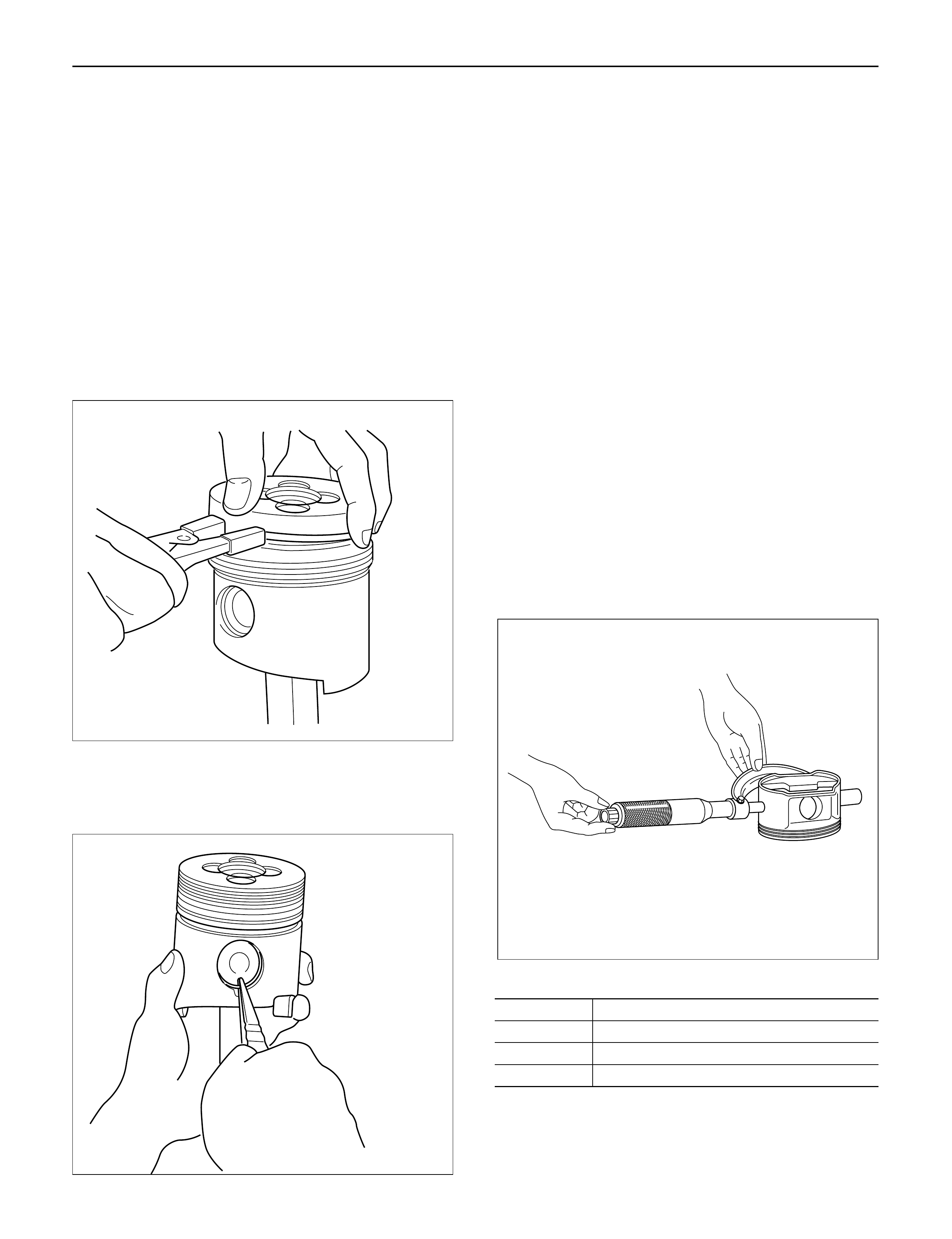
DISASSEMBLY
1.Cylinder Head Assembly
1)Refer to “Cylinder head” in this manual.
2. Crank Case Assembly
1)Refer to “Crank Case” in this manual.
3. Connecting Rod Bearing Cap
4. Piston and Connecting Rod
1) Remove carbon deposits from the upper portion
of the cylinder wall with a scraper before
removing the piston and connecting rod.
5. Piston Ring
Remove the piston rings with a piston ring
expander.
Arrange the removed piston rings in the cylinder
number order.
6. Piston Pin Snap Ring
1) Use a pair of pliers to remove the piston pin
snap rings.
7. Piston Pin
1) Remove piston pin from piston assembly.
NOTE: Keep the parts removed from each cylinder
separate. All parts must be reinstalled in their original
positions.
8. Piston
9. Connecting Rod
INSPECTION AND REPAIR
PISTON AND PISTON RING
Pistons
Carefully clean away all the carbon adhering to the
piston head and the piston ring grooves.
NOTE: Never use a wire brush to clean the pistons.
Damage will result. Visually check each piston for
cracking, scoring, and other signs of excessive wear. If
any of the above conditions are present, the piston
must be replaced.
Piston Diameter
1. Measure the piston outside diameter with
micrometer at the piston grading position.
Piston Grading Position: 69.75 mm (2.7461 in)
from piston head
Piston Outside Diameter mm(in)
Grade Mark Outside Diameter
A 95.320 – 95.329 (3.7527 – 3.7531)
B 95.330 – 95.339 (3.7531 – 3.7535)
C 95.340 – 95.349 (3.7535 – 3.7539)
015RW082
015RW077
015LV014
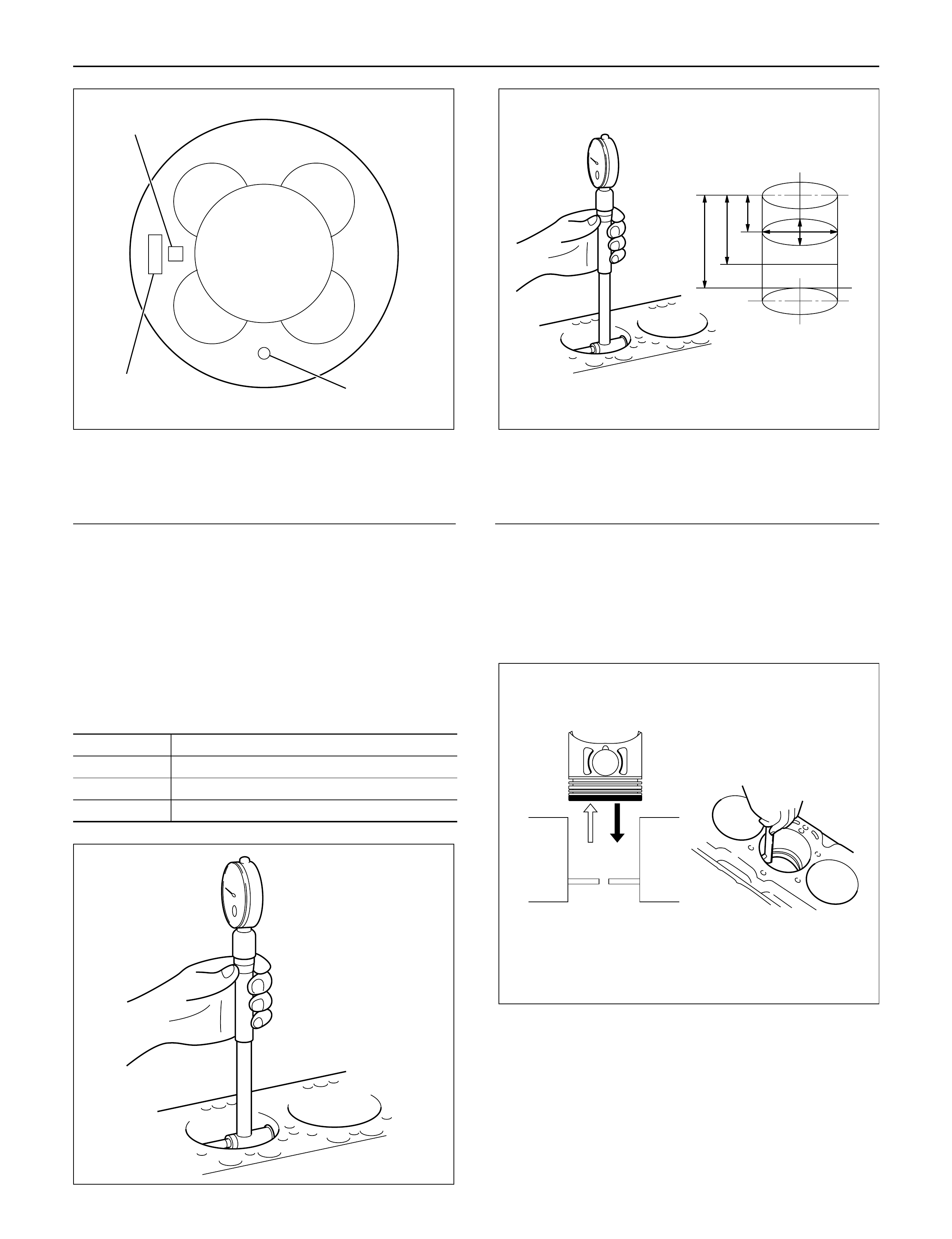
Legend
(1) Piston Grade
(2) Piston Front Mark
(3) Part Number
The grade for piston outside diameter is stamped
on the piston head.
Measure the cylinder bore diameter at measuring
points.
If the piston clearance does not conform to the
specified value, the pistons most be replaced.
Piston Clearance:
0.092 – 0.110 mm (0.0036 – 0.0043 in)
Cylinder Bore Diameter mm(in)
Grade Mark Cylinder Bore Diameter
A 95.421 – 95.430 (3.7567 – 3.7571)
B 95.431 – 95.440 (3.7571 – 3.7575)
C 95.441 – 95.450 (3.7575 – 3.7579)
Legend
Measuring point 1 = 20 mm
2 = 90 mm
3 = 160 mm
Piston rings
Any worn or damaged part discovered during engine
overhaul must be replaced with a new one.
1. Ring end gap measurement
1) Insert the piston ring into the cylinder bore.
2) Push the ring by the piston, at the right angle to
the wall, into the point at which the cylinder bore
diameter is the smallest.
3) Measure the ring end gap.
NOTE: The piston ring is stamped with a discerning
mark on the upper face of piston ring.
1
32
015RW080
012RW071
321
012RW117
012RW051
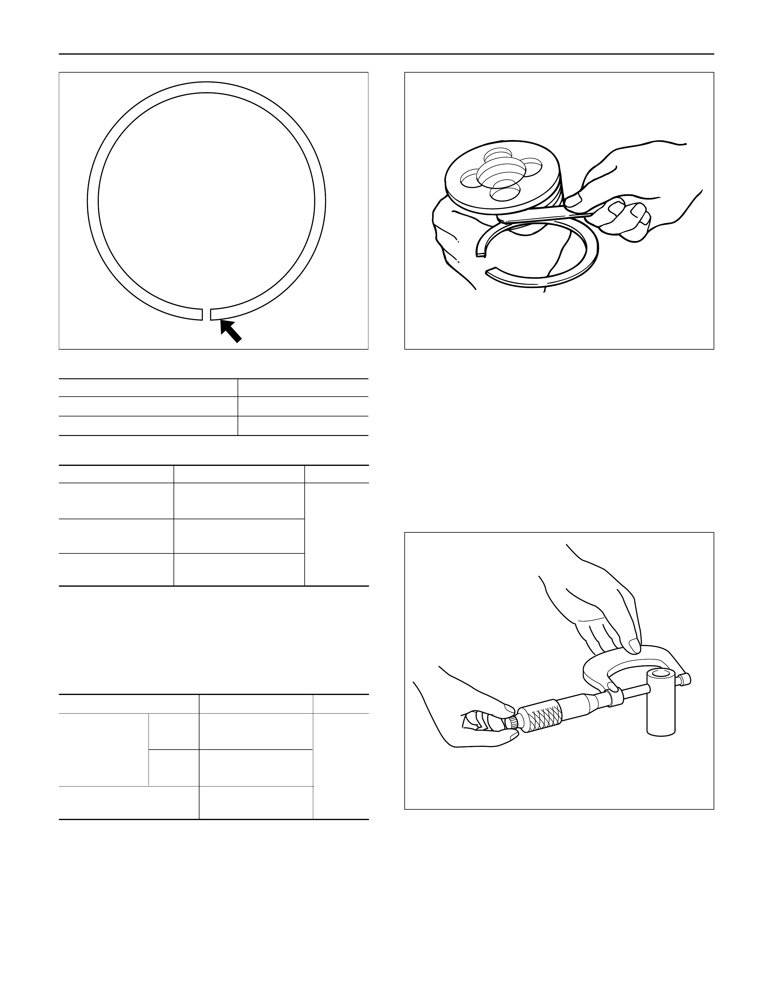
Discerning Mark
Piston Ring Discerning Mark
1st compression ring 1N
2nd compression ring 2N
Ring End Gap mm(in)
Piston Ring Standard Gap Limit
1st 0.25 – 0.40
compression ring (0.0098 – 0.0157)
2nd 0.20 – 0.35 1.5
compression ring (0.0079 – 0.0138) (0.0590)
Oil ring 0.10 – 0.30
(0.0039 – 0.0118)
2. Measure the clearance between the piston ring
groove and the piston ring with a feeler gauge. If the
piston ring groove/piston ring clearance exceeds
the specified limit, the piston and/or piston rings
must be replaced. mm(in)
Standard Limit
1st 0.05 – 0.09
Compression (0.0020 – 0.0035)
ring 2nd 0.05 – 0.09 0.15
(0.0020 – 0.0035) (0.0059)
Oil ring 0.03 – 0.07
(0.0012 – 0.0028)
Piston pin
Visually inspect the piston pin for cracks, flaws, and
other damage and replace if necessary.
1. Use a micrometer to measure the piston pin outside
diameter in both directions at three different
positions. If the measurement exceeds the
specified limit, the piston pin must be replaced.
Standard: 30.995 – 31.000 mm (1.2212 – 1.2214 in)
Limit: 30.97 mm (1.2202 in)
N
012RW037 015RW076
012RW082
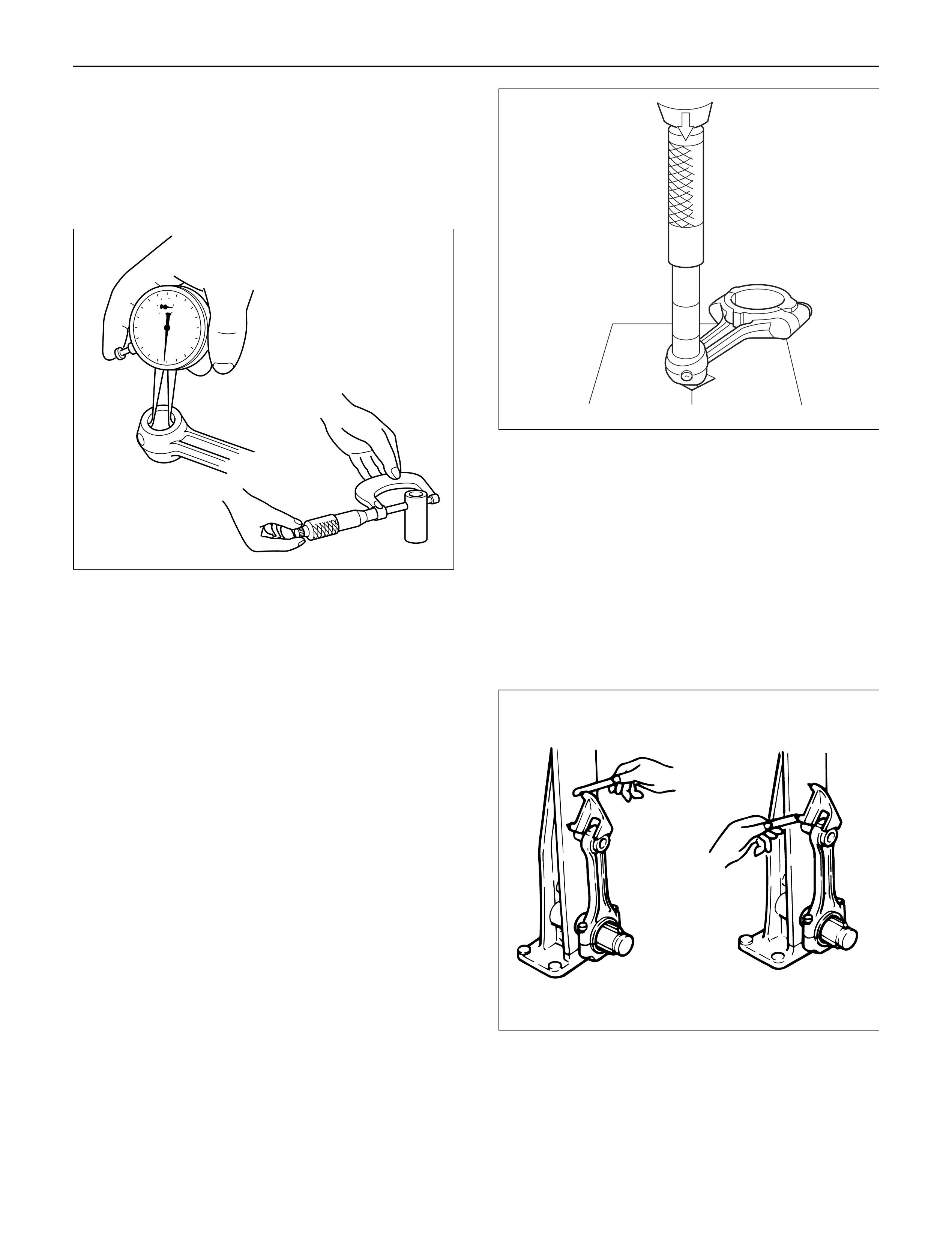
2. Measure the inside diameter of the connecting rod
small end. If the clearance between the small end
and pin does not conform to the specified value, the
connecting rod or bushing and pin must be
replaced.
Standard: 0.008 – 0.020 mm (0.0003 – 0.0008 in )
Limit: 0.05 mm (0.0020 in)
3. Insert the piston pin into the piston and rotate it. If
the pin rotates smoothly with no backlash, the
clearance is normal. If there is backlash or
roughness, measure the clearance. If the clearance
exceeds the specified limit, the piston and the
piston pin must be replaced.
Standard: 0.005 – 0.018 mm (0.0002 – 0.0007 in )
Limit: 0.04 mm (0.0016 in)
Bushing replacement
Removal: Use a suitable bar and bench press or
hammer
Installation: Align the bushing with a connecting rod
oil port. After installing a new bushing,
finish the bushing bore with a pin hole
grinder.
Connecting rods
1. Check the connecting rod alignment with a
connecting rod aligner.
If either the bend or the twist exceeds the specified
limit, the connecting rod must be replaced.
Bend per 100 mm (3.937 in)
Standard: 0.08 mm (0.0031 in) or less
Limit: 0.20 mm (0.0079 in)
Twist per 100 mm (3.937 in)
Standard: 0.05 mm (0.0020 in) or less
Limit: 0.15 mm (0.0059 in)
2. Measure the connecting rod thrust clearance.
Use a feeler gauge to measure the thrust clearance
at the big end of the connecting rod.
If the clearance exceeds the specified limit, the
connecting rod must be replaced.
Standard: 0.230 mm (0.0091 in)
Limit: 0.350 mm (0.0138 in)
012RW074
012RW123
012RW001
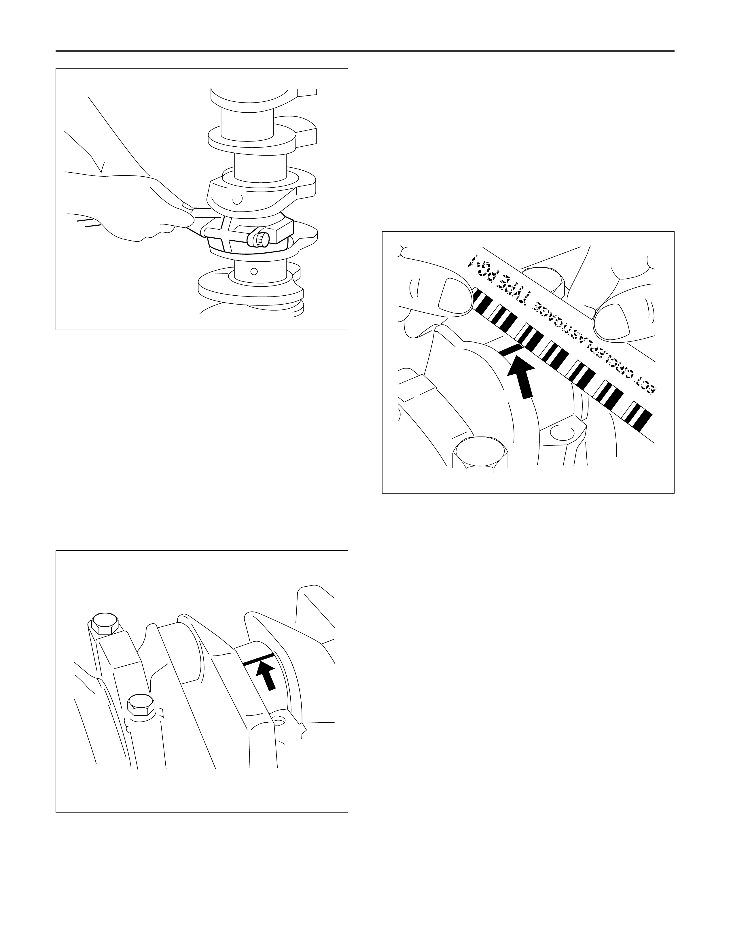
3. Measure the oil clearance between the connecting
rod and the crankshaft.
1) Remove the connecting rod cap nuts and the
rod caps.
Arrange the removed rod caps in the cylinder
number order.
2) Clean the rod bearings and the crankshaft pins.
3) Carefully check the rod bearings.
If even one bearing is found to be damaged or
badly worn, the entire bearing assembly must be
replaced as a set. Reinstall the bearings in their
original positions.
Apply plastigage to the crank pin.
4) Reinstall the rod caps to their original positions.
5) Tighten the cap nuts in 2 steps, using angular
tightening method as shown in the following
specifications.
1st step: 29 N·m (3.0 kg·m/22 lb ft)
2nd step: 45°– 60°
NOTE: Do not allow the crankshaft to rotate
6) Remove the rod caps.
7) Measure the smallest width of the plastigage
and determine the oil clearance. If the oil
clearance exceeds the limit, replace the rod
bearings as a set.
8) Clean the plastigage from the bearings and the
crankshaft pins
Standard: 0.022 – 0.042 mm (0.0009 – 0.0017 in)
Limit: 0.100 mm (0.0039 in)
REASSEMBLY
1. Connecting Rod
2. Piston
3. Piston Pin
1) Apply a coat of engine oil to the piston pin and
the piston pin hole.
4. Piston Pin Snap Ring
1) Try to insert the piston pin into the piston pin
hole with normal finger pressure.
2) Weight each piston and connecting rod
assembly.
3) Select piston and connecting rod combinations
so that the weight variation of the different four
assemblies is held within the specified limits.
Variance in weight after assembly: Less than 3g
(0.1058 oz)
NOTE: When changing piston/connecting rod
combinations, do not change the piston/piston pin
combination.
4) Attach the piston to the connecting rod with the
piston front mark (2) and the connecting rod
front mark (3) on the same side.
014RW055
012RW075
014RW077
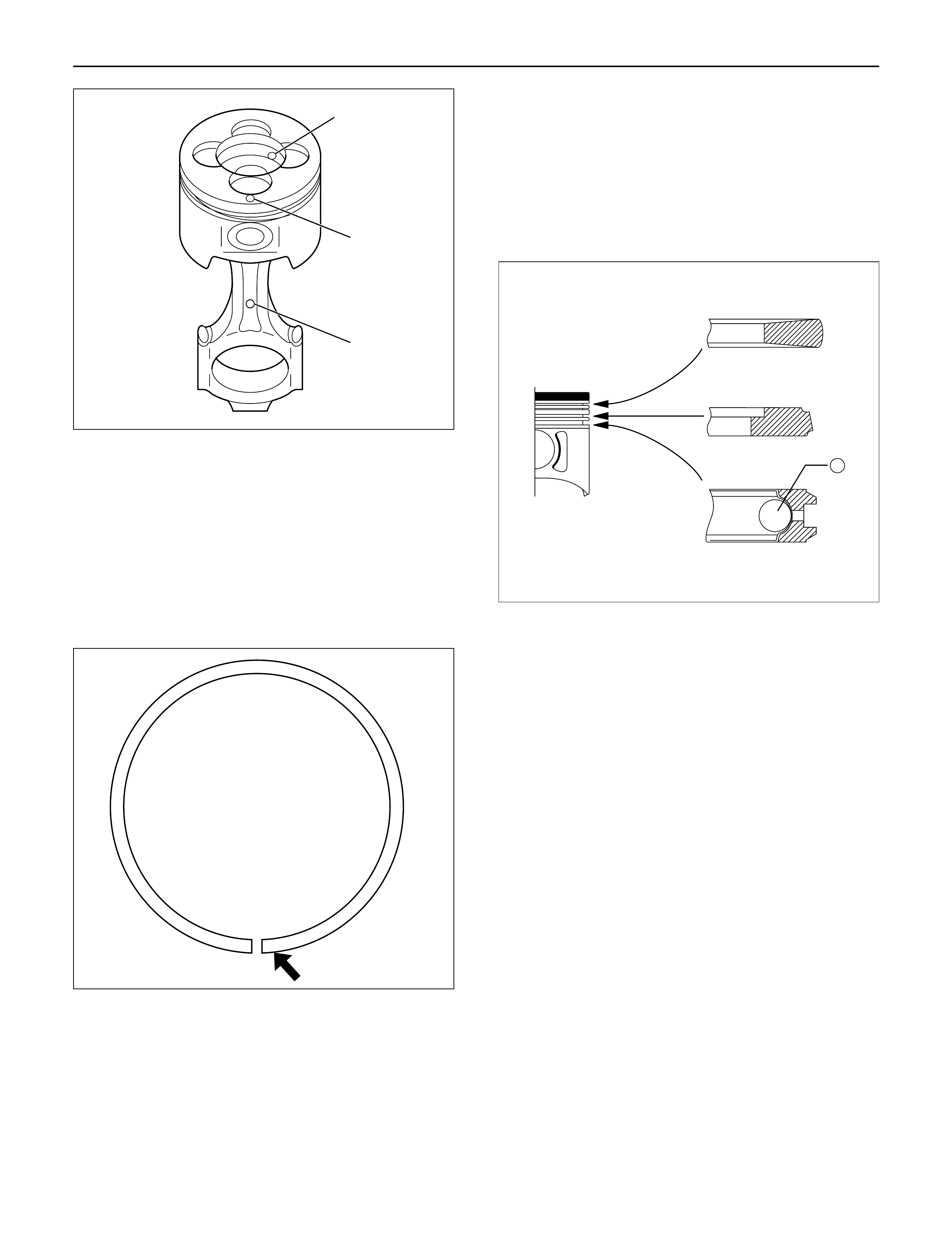
5. Piston Ring
1) Install the piston rings with the piston ring
expander.
The compression ring must be set with the 1N,
2N mark facing up.
2) Discerning mark is stamped as shown in the
illustration (1).
Marked 1N: 1st compression ring
Marked 2N: 2nd compression ring
3) Install piston rings in the following sequence.
1) Oil ring
(1)After installing the expander ring then assemble
the oil ring.
2) 2nd compression ring
3) 1st compression ring
1) The compression ring must be set with the 1N or
2N mark facing up.
2) 1st compression ring:1N
3) 2nd compression ring: 2N
4) After installation, apply engine oil to the entire
circumference of the piston rings.
Check to see that all the rings rotate smoothly.
5) Insert the bearings into the connecting rods and
caps.
Apply new engine oil to the bearing faces.
Cap side bearings have no oil hole.
Connecting rod side bearing’s oil hole should be
aligned with oil hole on the connecting rod.
6. Piston and Connecting Rod
1) Apply engine oil to the cylinder bores, the
connecting rod bearings and the crankshaft
pins.
2) Check to see that the piston ring end gaps are
correctly positioned.
N
012RW037
2
3
1
015RW051
3
2
11
012RW058
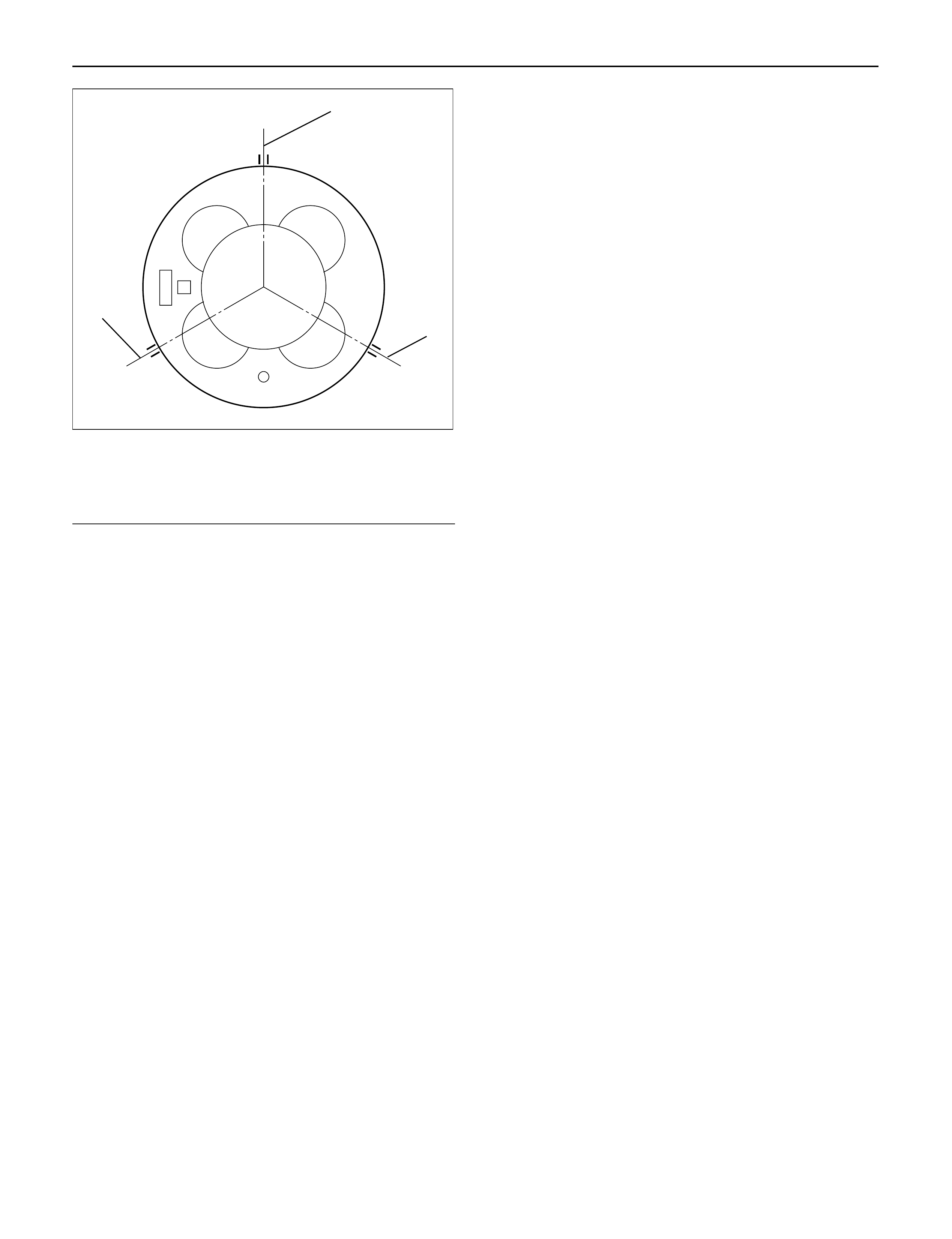
Legend
(1)1st compressor ring gap
(2)2nd compressor ring gap
(3)Oil ring gap
3)Insert the piston/connecting rod assemblies into
each cylinder with the piston ring compressor.
4)The front marks must be facing the front of the
engine.
Piston Ring Compressor : 5-8840-9018-0
7.Connecting Rod Bearing Cap
1)Apply engine oil to thread and seat of bearing
cap bolts.
2)Tighten the cap bolts in 2 steps, using angular
tightening method as shown in the following
specifications.
1st step: 29 N·m (3.0 kg·m/22 lb ft)
2nd step: 45°– 60°
After tightening the cap bolts, check to see that
the crankshaft rotates smoothly.
8.Crank Case Assembly
1)Refer to “Crank Case” in this manual.
9. Cylinder Head Assembly
1)Refer to “Cylinder head” in this manual.
3
1
2
015RW083
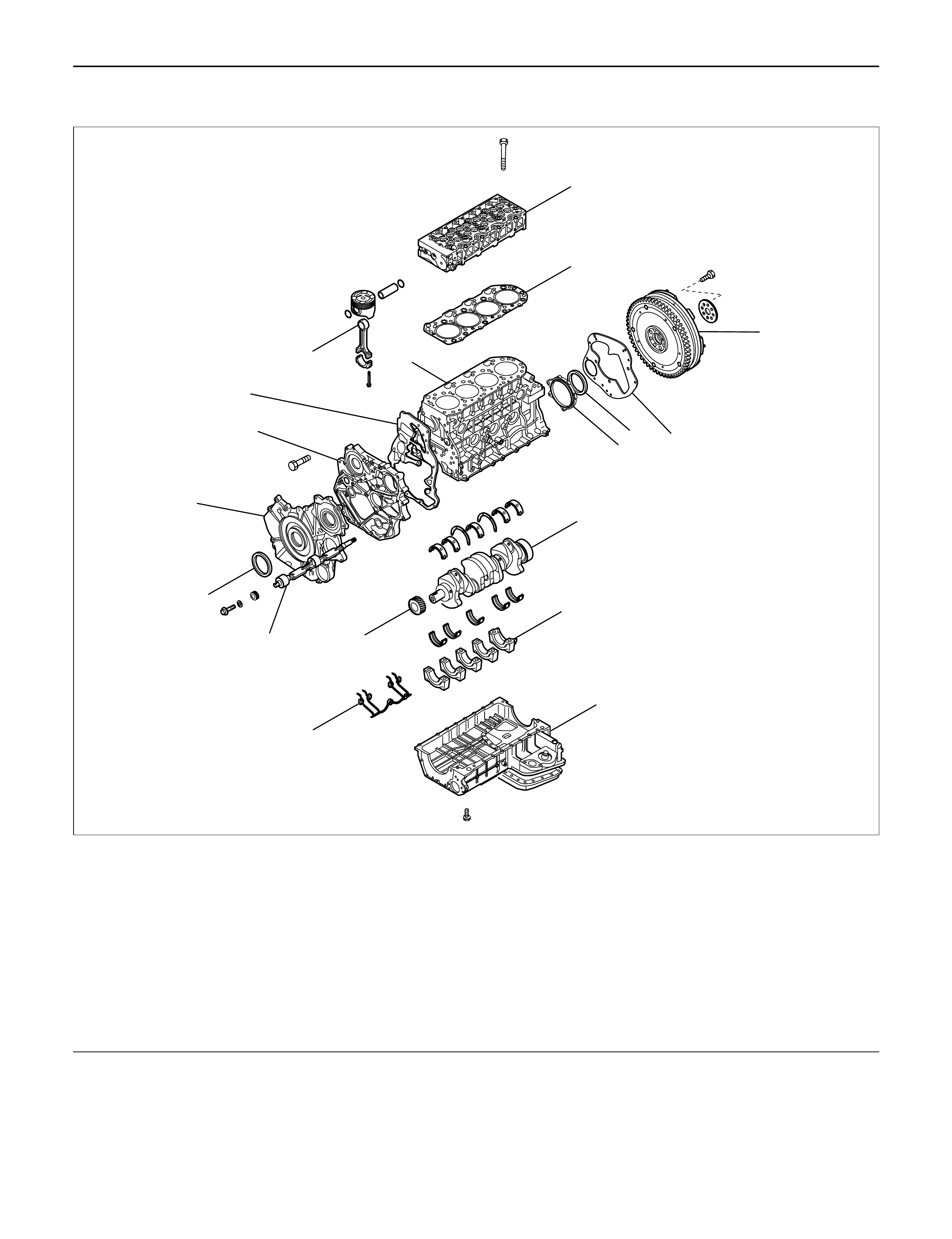
CYLINDER BLOCK
1
15
14
13
8
11 16
17
10
9
7
2
12
3
4
65
18
012RW023
Legend
(1) Cylinder Head
(2) Cylinder Head Gasket
(3) Flywheel
(4) Cylinder Block Rear Plate (A/T)
Flywheel Housing (M/T)
(5) Crankshaft Rear Oil Seal
(6) Retainer
(7) Timing Gear Case Cover
(8) Crankshaft Front Oil Seal
(9) Timing Gear Case
(10) Gasket
(11) Balance Shaft
(12) Crank Case
(13) Piston Cooling Oil Pipe
(14) Main Bearing Cap
(15) Crankshaft
(16) Crankshaft Timing Gear
(17) Piston and Connecting Rod Assembly
(18) Cylinder Block
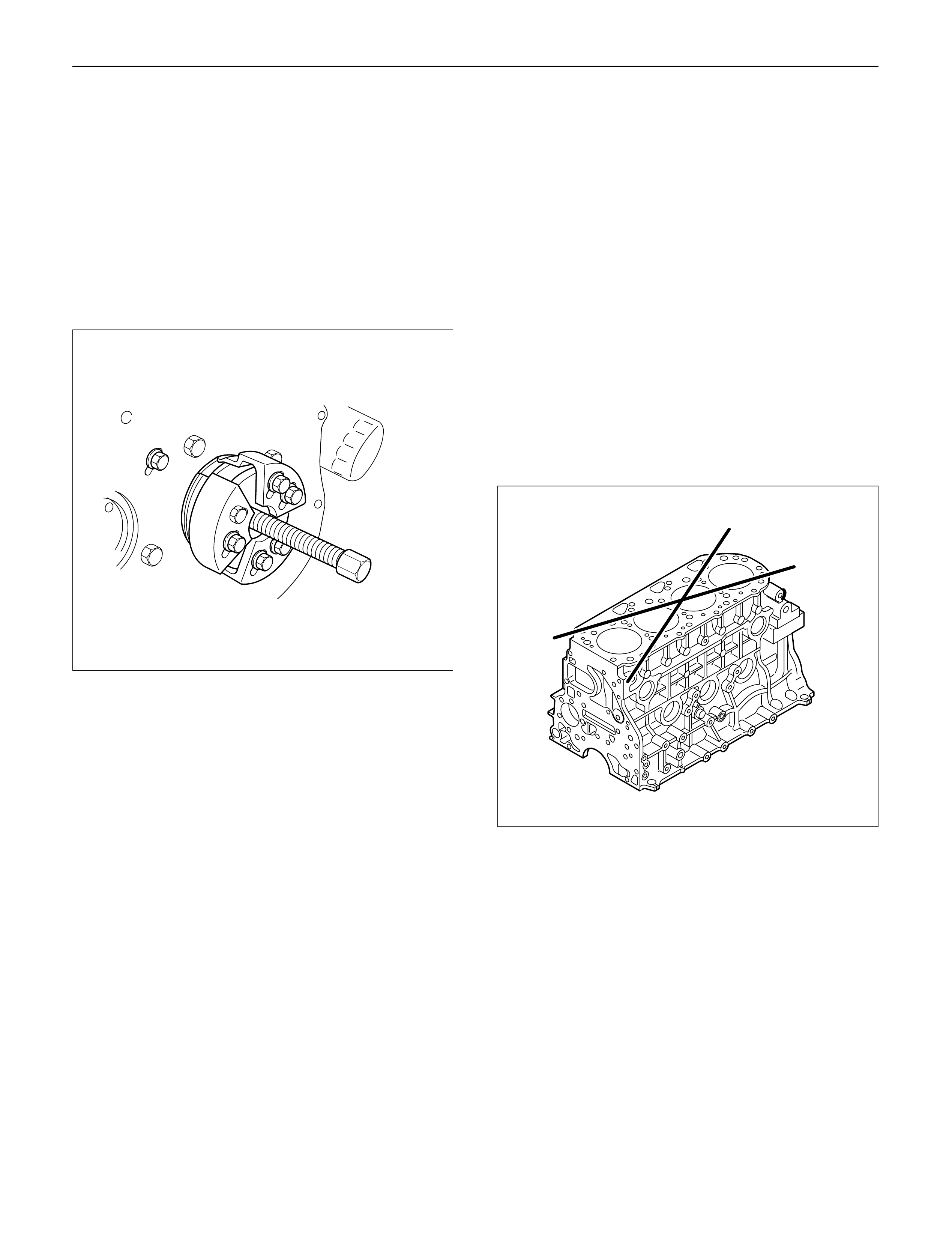
DISASSEMBLY
1.Cylinder Head Assembly
Refer to “Cylinder Head” in this manual.
2.Cylinder Head Gasket.
3.Flywheel
4.Cylinder Block Rear Plate (A/T), or Flywheel
housing (M/T).
5.Crankshaft Rear Oil Seal.
Install the special tool as shown in the illustration
and remove the oil seal.
Oil Seal Remover: 5-8840-2360-0
6.Retainer
7.Timing Gear Case Cover
8.Crankshaft Front Oil Seal
1)Use a plastic hammer and a screwdriver to tap
around the oil seal to free it from the gear case
cover.
9.Timing Gears
Refer to “Timing Gear” in this manual.
10. Timing gear case
11. Gasket
12. Balance shaft (right)
13. Crank case assembly
14. Piston cooling oil pipe
15. Piston assembly
16. Main bearing cap
17. Crankshaft assembly
18. Cylinder block side cover right and left
19. Cylinder block
INSPECTION AND REPAIR
Make the necessary adjustments, repairs, and part
replacements if excessive wear or damage is
discovered during inspection.
1. Remove the cylinder head gasket and any other
material adhering to the upper surface of the
cylinder block.
Be very careful not to allow any material to
accidentally drop into the cylinder block.
Be very careful not to scratch the cylinder block.
2. Carefully remove liquid gasket, which was used
when assembled, from gear case, rear oil seal
retainer and crank case.
3. Wipe the cylinder block clean and visually check it.
4. Use a straight edge and a feeler gauge to measure
the four sides and the two diagonals of the cylinder
block upper face.
If the measured values exceed the limit, the cylinder
block must be replaced.
Limit: 0.20 mm (0.0079 in)
015RV002
012RW122
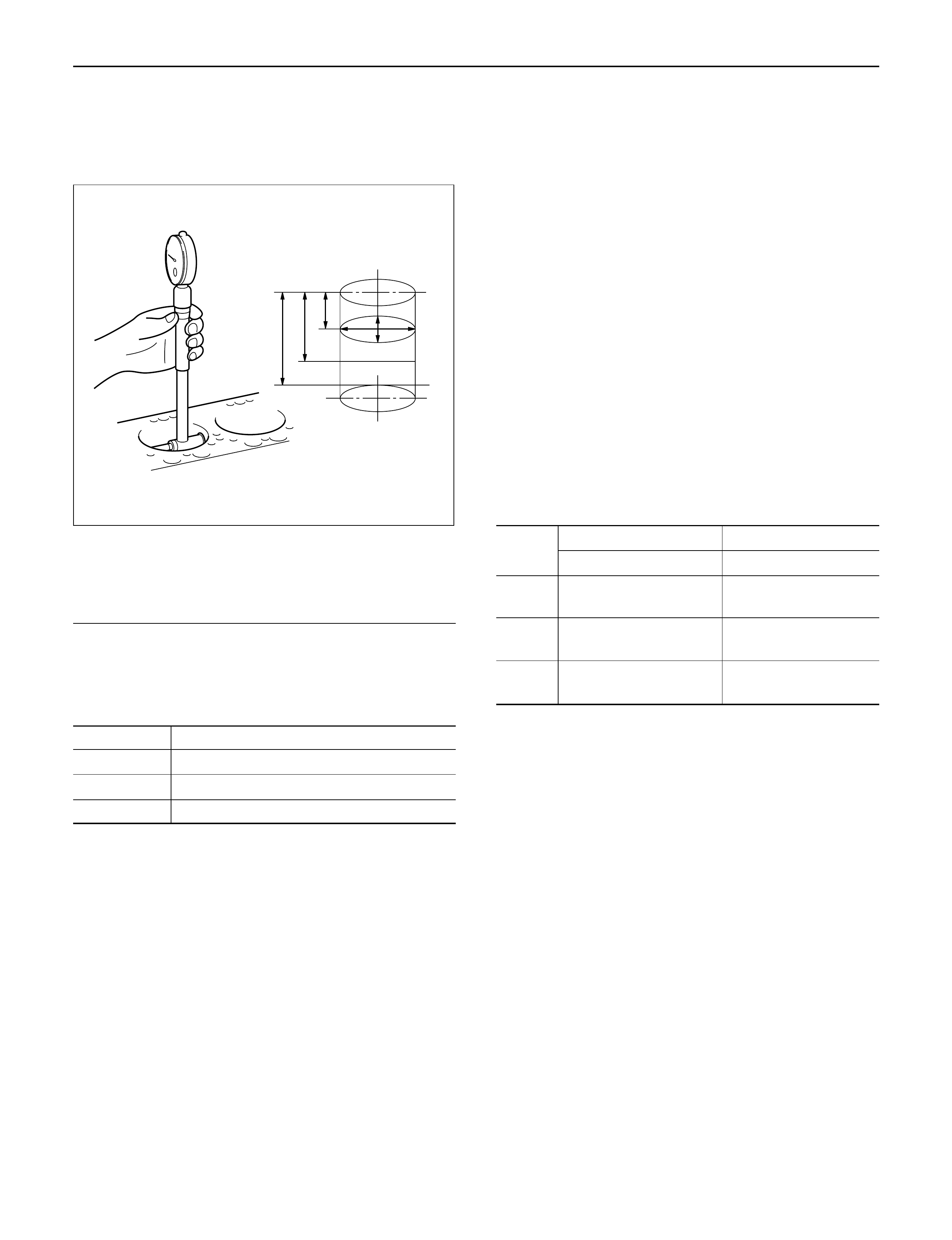
Cylinder Bore Measurement
1. Use a cylinder gauge to measure the cylinder bore
measuring direction for thrust and radial at
measuring points.
Legend
Measuring Point 1; 20 mm
2; 90 mm
3; 160 mm
2. Select the right piston grade by the averaged
cylinder bore measurement (maximum and
minimum value eliminated).
Cylinder bore diameter mm(in)
Grade mark Standard
A 95.421 – 95.430 (3.7567 – 3.7571)
B 95.431 – 95.440 (3.7571 – 3.7575)
C 95.441 – 95.450 (3.7575 – 3.7579)
3. If measured values exceed the limit, replace or
adjust the cylinder block honing or boring.
Limit 95.950 mm (3.7776 in)
4. Boring of the cylinder bore is allowed until it is
0.5 mm (0.0197 in) diameter and oversized piston
is available as a service part.
Boring Cylinder Block
1. Use an oversized piston on the basis of above
mentioned cylinder using the largest inside
diameter.
2. Measure the piston outside diameter at right angles
with piston pin at a piston grade measuring point
69.75 mm (2.7461 in) from piston top surface and
calculate a inside diameter for cylinder boring.
3. Calculation of cylinder bore boring.
D + C – H (mm)
D; Outside diameter piston (mm)
C; Clearance between Cylinder bore and piston
0.092 – 0.110 mm (0.0036 – 0.0043 in)
H; Honing allowance
Less than 0.03 mm (0.0012 in)
The oversize pistons are available three grades.
4. Honing the cylinder bore after boring.
5. Measure cylinder bore after honing.
Difference between each cylinder bore
Less than 0.02 mm (0.0008 in)
Cylinder bore and piston grade (After boring) mm(in)
Grade Oversize Piston Bore
Mark Outside Diameter Diameter
A95.820 – 95.829 95.921 – 95.930
(3.7724 – 3.7728) (3.7764 – 3.7768)
B95.830 – 95.839 95.931 – 95.940
(3.7728 – 3.7732) (3.7768 – 3.7772)
C95.840 – 95.849 95.941 – 95.950
(3.7732 – 3.7736 ) (3.7772 – 3.7776)
REASSEMBLY
1. Cylinder Block
2. Piston Cooling Oil Pipe
1) Fix the cooling jet pipes with knock pins on the
cylinder block.
2) Install the oil pipe for piston cooling in the
cylinder block, tightening a relief valve (1) and
four joint bolts (2) to the specified torque.
If oil jet pipe is forcibly assembled, the end of oil
jet may bend. It could make it impossible to
supply oil to the piston cooling hole, sometimes
causing piston seizure.
Sufficient care should be taken to pipe assembly
work.
321
012RW117
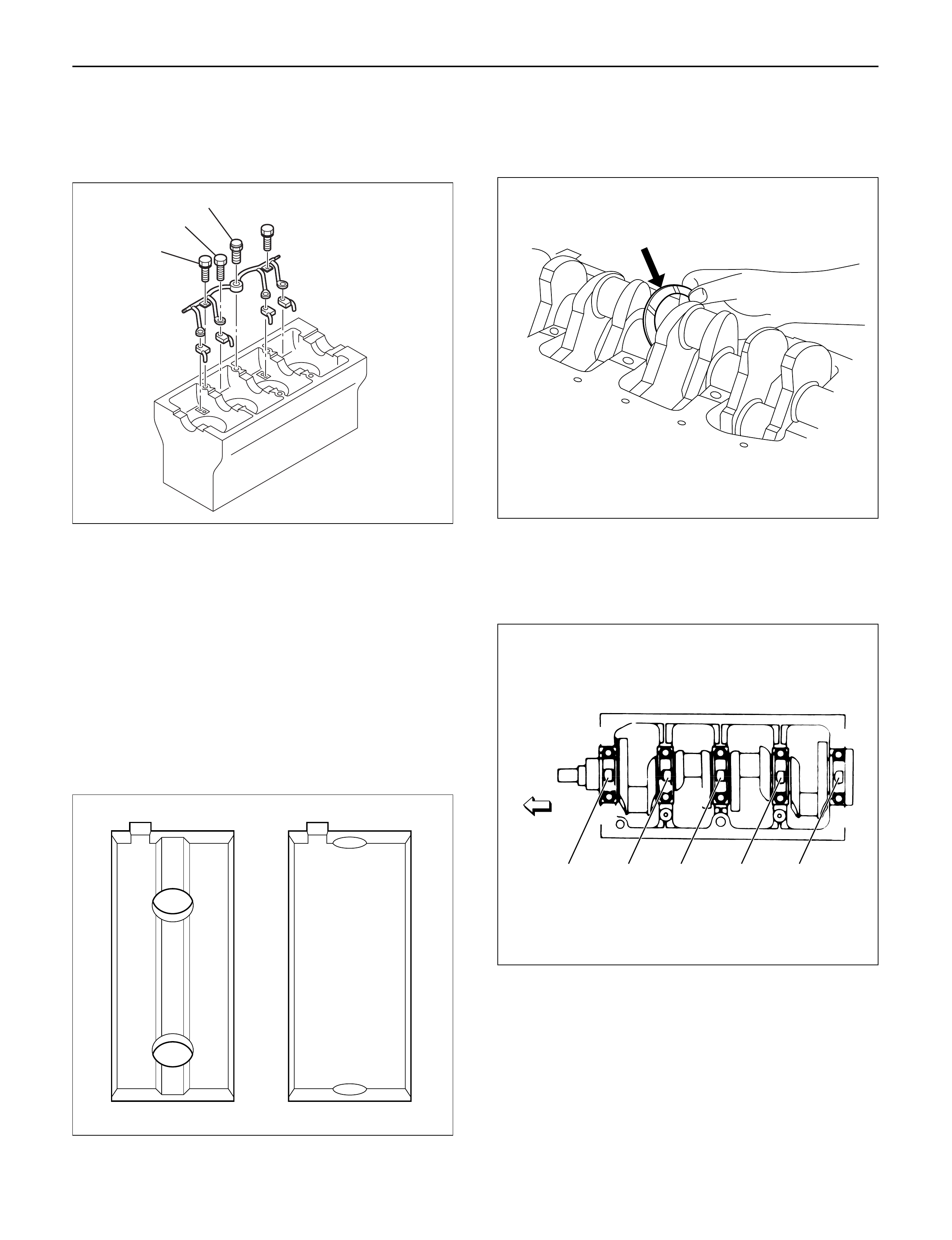
Oil pipe fixing bolts
M8: 20 N·m (2.0 kg·m/14 lb ft)
M6: 8 N·m (0.8 kg·m/69 lb in)
Relief valve fixing bolts : 30 N·m (3.1 kg·m/22 lb ft)
CAUTION: After installing the piston assembly,
check and see that there is appropriate clearance
between pistons and oil jet pipes by rotating
crankshaft slowly.
3. Crankshaft
1) Install the main bearings to the cylinder body
and the main bearing caps.
2) Be sure that they are positioned correctly.
3) Apply new engine oil to the upper and lower
main bearing faces.
4) Carefully mount the crankshaft.
5) Apply engine oil to the thrust washer.
6) Assemble the thrust washer to the No. 3
bearing journal. The oil grooves must face the
crankshaft.
4. Main Bearing Cap Assembly
1) Install the main bearing caps with the main
bearing cap head arrow mark facing the front of
the engine.
2) Apply engine oil to the main bearing cap bolts.
3) Tighten the main bearing cap bolts to the
specified torque a little at a time in the sequence
shown in the illustration.
Torque: 167 N·m (17.0 kg·m/123 lb ft)
3
2
1
012RW076
012RW038
012RW047
1 2 3 4 5
012RW025
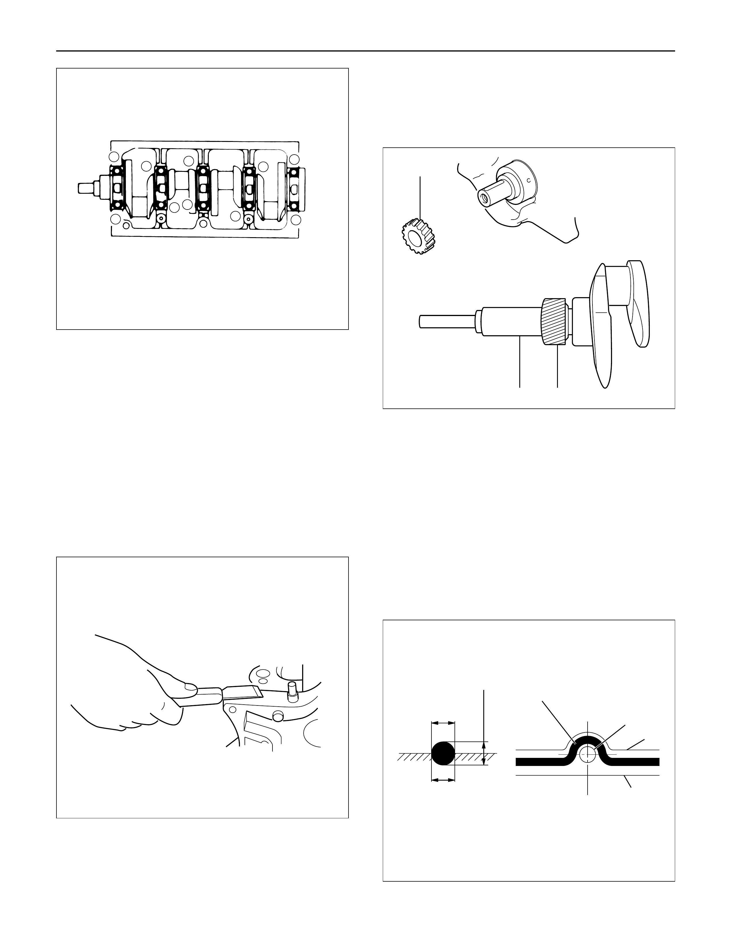
NOTE:Check to see that the crankshaft turns
smoothly by rotating it manually.
4.Piston Assembly
1)Refer to “Piston and connecting rod” in this
manual.
5.Cylinder Block Side Cover Right and Left
6.Balance ShaftRight.
Apply new engine oil to the balance shaft (right) and
insert it into cylinder block.
7.Timing Gear Case
1)Cut out the liquid gasket forced out from
between the contact surface of cylinder block
and crankshaft.
2)Apply liquid gasket (TB1207B or equivalent) to
the fitting surface of the cylinder block and
crankcase.
3)Install timing gear case with gasket to cylinder
block and tighten to specified torque.
Torque: 20 N·m (2.0 kg·m/14 lb ft)
8.Crankshaft Gear
Force key into crankshaft and force in crankshaft
gear along the key groove using a special tool (1)
with the crank gear (2) timing mark facing outside.
9.Install timing gear align the timing mark on each
timing gear.
For alignment of timing marks refer to “Timing
Gear” in this manual.
NOTE: Remove the locking bolt or pin from idle gear A
and idle gear C.
10. Assembling the gear case cover.
1) Install the oil seal on the oil pump assembly
before installing the gear case cover.
2) Apply liquid gasket to timing gear case.
NOTE: Be sure to apply liquid gasket evenly.
84159
610
2
3
7
012RW027
012RW064
12
2
012RW066
2
2~2.5mm
2~2.5mm
Apply liquid gasket around inside
of the bolt hole
Bolt hole
Inside
Outside
F06HX00001
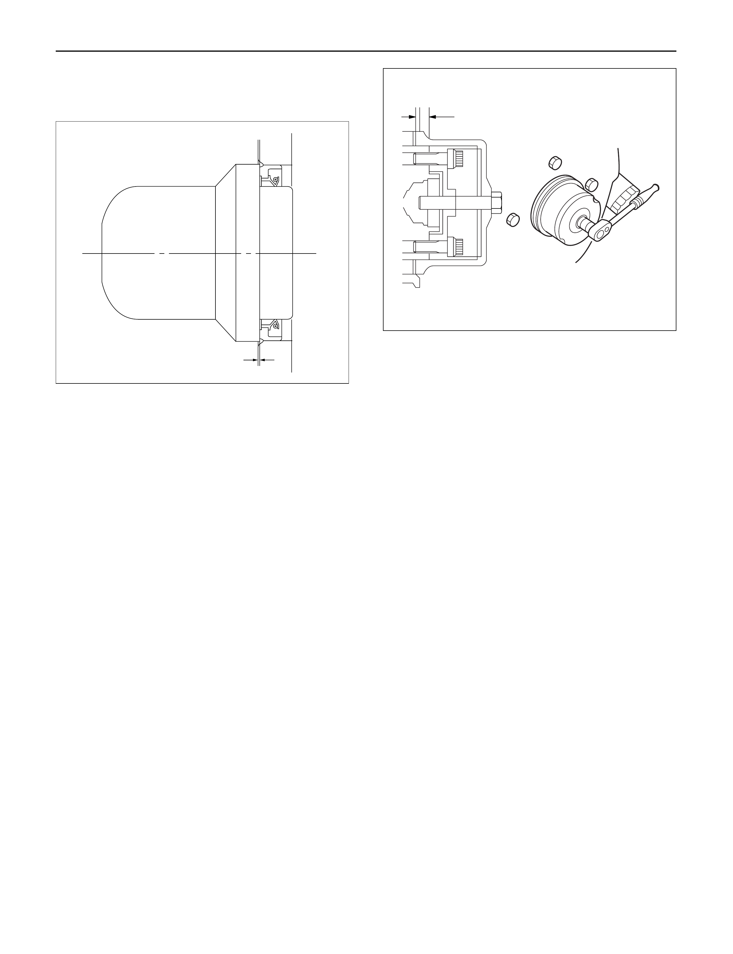
11.Use the special tool to install the crankshaft front oil
seal to timing gear case.
Front Oil Seal Installer: 5-8840-2061-0
1)Check fit-of the oil seal and gear case cover at
the front end.
Standard: 0.5 – 2.5 mm (0.0197 – 0.0984 in)
NOTE:Apply engine oil to oil seal lip before installation
of the seal.
12.Install the oil pan assembly to original position and
tighten to specified torque.
Torque: 22 N·m (2.2 kg·m/16 lb ft)
13.Crankshaft Rear Oil Seal
1)Tighten the adapter to the crankshaft rear end
with 2 bolts.
2)Insert the oil seal into the adapter.
NOTE: Apply oil to oil seal lip.
3)Insert the sleeve into the adapter and tighten it
with a bolt (M12 x 1.75L= 70) until the adapter
hits the sleeve.
4)Remove the adapter and the sleeve.
5)With the seal pressed in, check the dimension of
the oil seal outside end and crankshaft end.
Standard Dimension = 12.5 ±0.3 mm
Oil Seal Installer: 5-8840-2359-0
14.Cylinder Block Rear Plate (A/TModel)
1)Tighten the cylinder block rear plate fixing bolts
to the specified torque.
Torque: 97 N·m (9.9 kg·m/72 lb ft)
15.Flywheel Housing (M/TModel)
1)Install flywheel housing aligned with the dowel
pin on the cylinder block.
2)Tighten the flywheel housing fixing bolts to the
specified torque.
Torque: 97 N·m (9.9 kg·m/72 lb ft)
16.Flywheel
1)Refer to “Crankshaft” in this manual.
17. Cylinder Head Assembly
1)Refer to “Cylinder Head” in this manual.
015RW074
12.5 + 0.3
–
012RW067
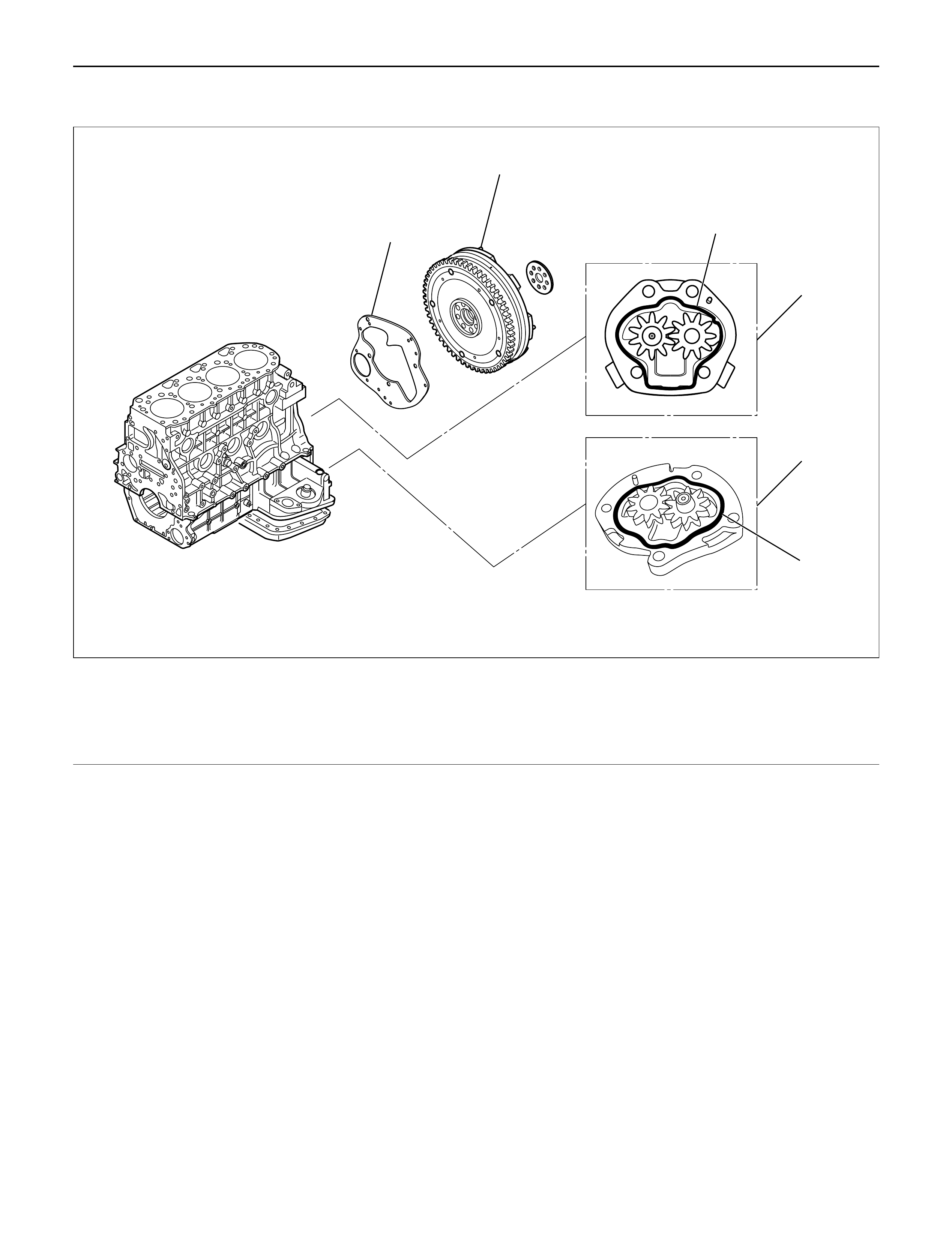
OILPUMPASSEMBLY
2
1
5
6
3
4
012RW097
Legend
(1) Flywheel
(2) Rear Plate (A/T)
(3) First Oil Pump Assembly
(4) Second Oil Pump Assembly
(5) O-Ring (For first oil pump)
(6) O-Ring (For second oil pump)
REMOVAL
1. Disconnect battery ground cable
2. Lift up car
3. Drain engine oil
NOTE: Install drain plug with new gasket.
4. Flywheel
5. Rear Plate (A/T) or Flywheel Housing (M/T)
6. First Oil Pump Assembly and Second Oil Pump
Assembly
1) Remove oil pump assembly from cylinder block
and crankcase.
INSTALLATION
1. First oil pump assembly
1) Set O-ring to oil pump.
2) Install oil pump drive gear to the rear end of the
balance shaft RH.
3) Apply engine oil to pump gear, install pump gear
to rear end of cylinder block with specified
torque.
Torque: 20 N·m (2.0 kg·m/14 lb ft)
2. Second oil pump assembly
1) Set O-ring to oil pump.
2) Install oil pump drive gear to the rear end of the
balance shaft LH.
3) Apply engine oil to pump gear, install pump gear
to rear end of crank case with specified torque.
Torque: 20 N·m (2.0 kg·m/14 lb ft)
3. Install rear plate (A/T) or flywheel housing (M/T)
Torque: 97 N·m (9.9 kg·m/72 lb ft)
4. Install flywheel
1) Apply engine oil to bolt and tighten with angular
tightening method.
1st step: 59 N·m (6.0 kg·m/43 lb ft)
2nd step: 60° to 90°
3rd step: 60° to 90°
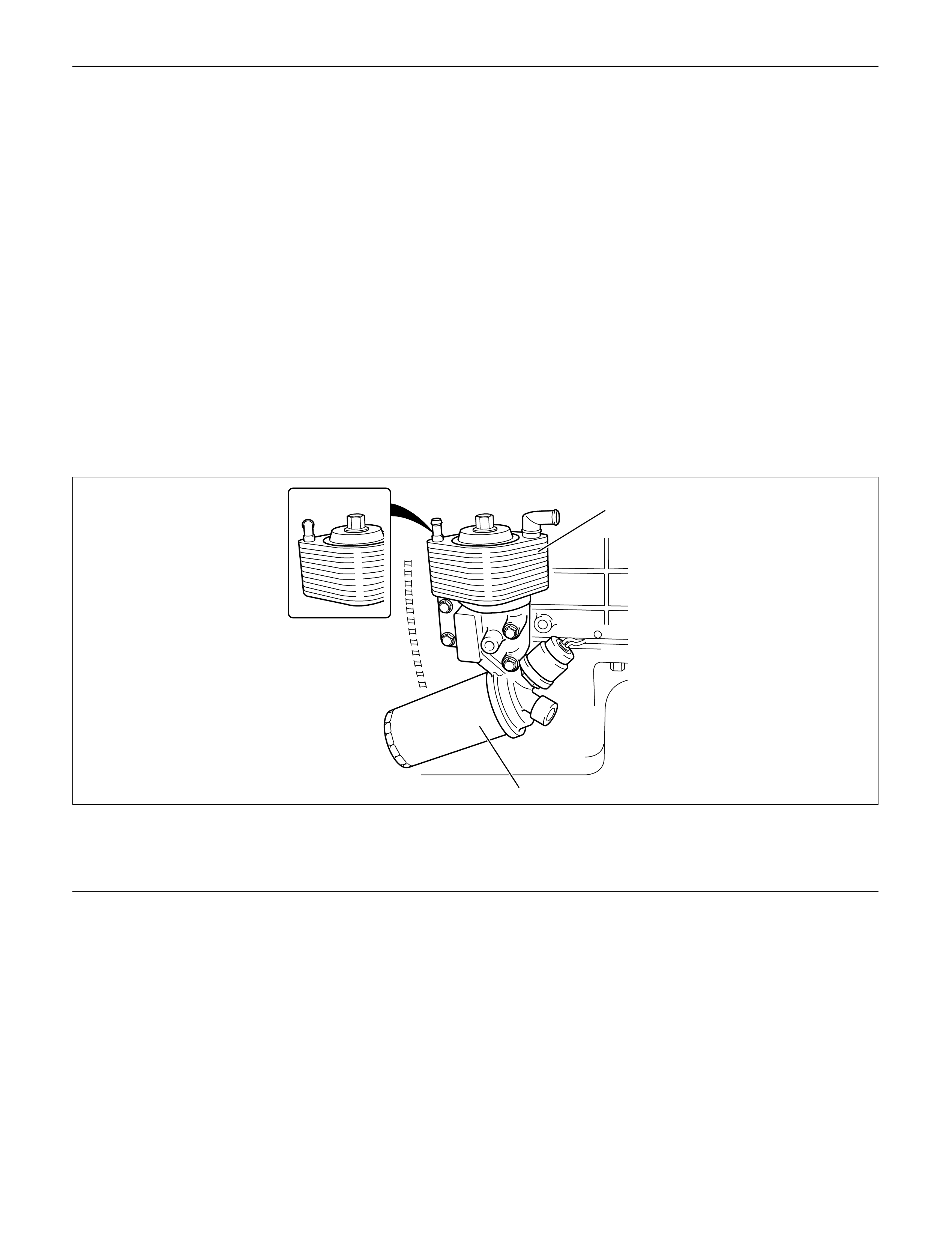
OILCOOLER
MY2003 Euro-3 1
2
050R200001
Legend
(1) Oil Cooler Assembly
(2) Oil Filter Cartridge
OILFILTER CARTRIDGE
REMOVAL
1. Place a receptacle beneath the oil filter to contain
the drained oil.
2. Remove the oil filter cartridge using filter wrench.
Filter wrench : 5-8840-0203-0
INSTALLATION
1, Lightly apply oil to the O-ring of oil filter cartridge.
2. Turn the new oil filter cartridge by hand until the
sealing face is fitted against the O-ring.
3. Use the filter wrench to turn the oil filter an
additional one and 1/8 turns.
4. Start the engine and check for oil leakage from oil
filter.

6A – 100 ENGINE MECHANICAL
REMOVAL
1. Disconnect battery ground cable
2. Drain engine coolant
3. Remove front exhaust pipe
4. Remove heat protector
5. Remove exhaust valve assembly
6. Oil cooler assembly
1) Remove water hoses from inlet and outlet pipe.
2) Put rag beneath side of oil cooler to prevent oil
leaking.
3) Remove fixing bolts and oil cooler assembly.
INSTALLATION
1. Oil Cooler
1) Tighten oil cooler fixing bolt to the specified
torque and connect water hose.
Torque: 29 N·m (3.0 kg·m/22 lb ft)
2. Exh. Valve Assembly
1) Install exhaust valve assembly with gasket and
tighten fixing bolts to the specified torque.
Torque: 57 N·m (5.8 kg·m/42 lb ft)
3. Heat Protector
4. Front Exhaust Pipe
1) Install front exhaust pipe and tighten fixing bolts
to the specified torque.
Exh. Valve Side: 67 N·m (6.8 kg·m/49 lb ft)
Intermediate Pipe Side: 43 N·m (4.4 kg·m/32 lb ft)
5. Fill engine coolant.
6. Connect battery ground cable.
7. Start engine and check for oil and water leakage
carefully.