
SECTION 6C ENGINE FUEL
GENERAL DESCRIPTION
General Description
On-Vehicle Service
Fuel Filter Assembly
Fuel Filter Cartridge
Injector
Fuel Pump Pipe
High Pressure Oil Pump
Fuel Tank
Fuel Gauge Unit
Fuel Filler Cap
To ensure the compatibility between low exhaust
emission and high engine output, an HEUI
(Hydraulically actuated Electronically controlled Unit
Injector) system, has been adopted. This system is
comprises of a hydraulic system, fuel system, and
electronic control system, using a high-pressure oil
pump in place of the conventional fuel injection pump.
The oil pressurized by means of this pump and by
signals from the ECM (Electronic Control Module)
actuates the fuel injector provided for each cylinder.
Inside of the fuel injector, fuel pressure is increased due
to the high-pressure oil. The ECM detects the driving
state of the vehicle, forms, signals sent by engine and
other part sensors, which determines the optimum fuel
injection amount and timing, thus controlling the fuel
injectors. Thus high engine output, good fuel economy,
and low exhaust emission are realized.
IMPORTANT
For MY2003, a number of modifications were made to
the engine mechanical design and the engine fuel,
air intake and exhaust systems.
The engine fuel system modifications include the
fitment of revised injectors and a new fuel calibration
for the ECM.
Always ensure the correct components and ECM
calibration are used when conducting any servicing
procedures on the 4JX1-TC engine.
Always refer to the latest issue of Holden Partfinder to
correctly identify replacement part.
When working on the fuel system, there are several
things to keep in mind:
1) Any time the fuel system is being worked on,
disconnect the negative battery cable except for
those tests where battery voltage is required.
2) Always keep a dry chemical (Class B) fire
extinguisher near the work area.
3) Replace all pipes with the same pipe and fittings
that were removed.
Clean and inspect 'O' rings. Replace where
required.
4) Always relieve the line pressure before servicing
any fuel system components.
5) Do not attempt repairs on the fuel system until you
have read the instructions and checked the pictures
relating to that repair.
6) After maintenance work, push priming pump and
send enough fuel to the fuel system before starting
the engine.
NOTE: In comparison with the conventional engine,
the capacity of fuel passage in the 4JX1 engine is
larger. It takes the priming pump more time to fill the
system with fuel. Keep this in mind when servicing the
fuel system.
Techline
Techline
Techline
Techline
Techline
Techline
Techline
Techline
Techline
Techline
Techline
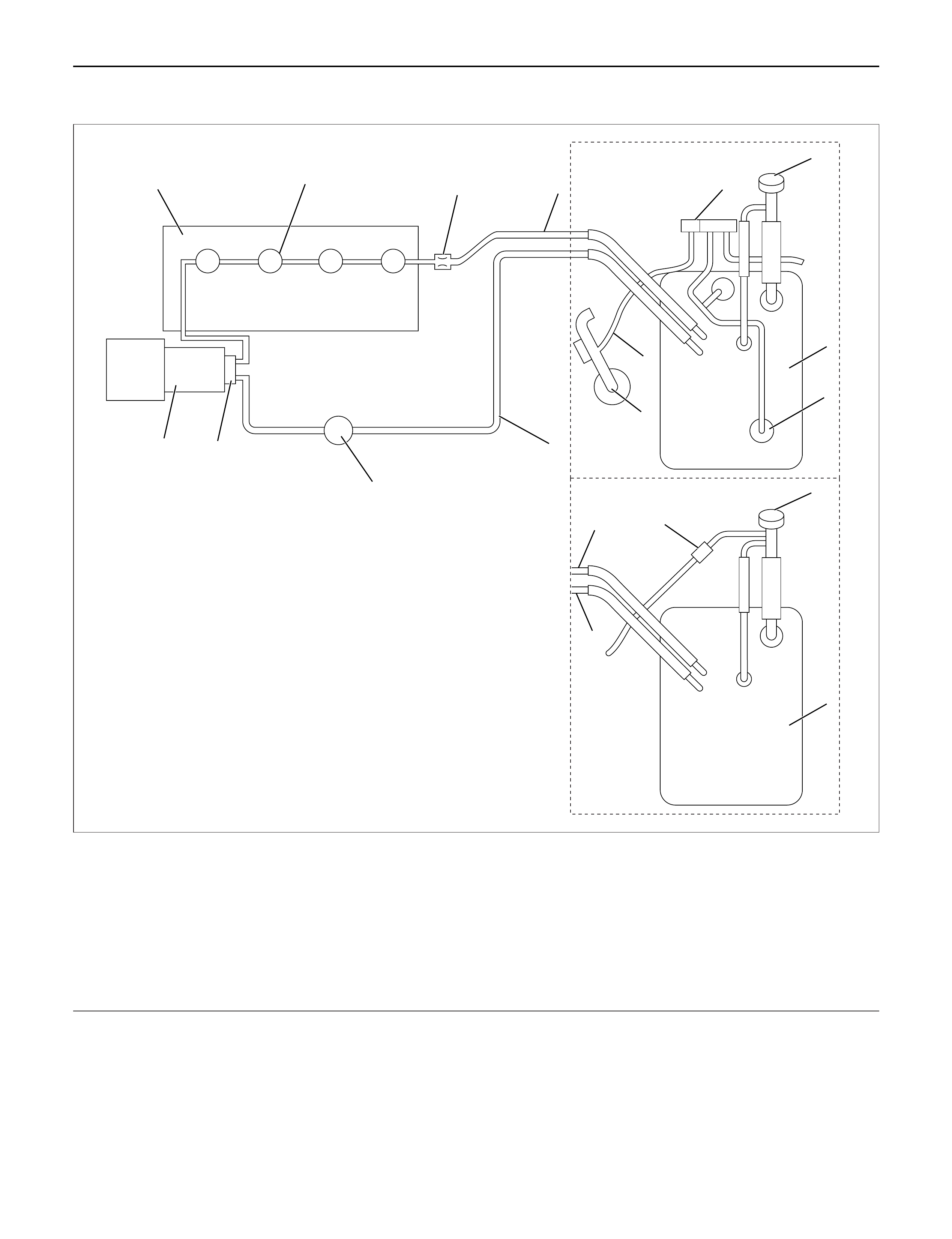
FUEL FLOW
1
14
MY1998-2002 Euro-2
8910 11
1
2
2
4
12
5
6
7
3
13
14
MY2003 Euro-3
11
4
Legend
(1) Fuel Filler Cap
(2) Fuel Tank
(3) Rollover Valve
(4) Fuel Supply Pipe
(5) Fuel Filter with Priming Pump
(6) Fuel Pump
(7) High Pressure Oil Pump
(8) Cylinder Head
(9) Injector
(10) Orifice
(11) Fuel Return Pipe
(12) Fuel Tank Pressure Release Hose
(13) Intake Air Duct
(14) Fuel Tank Pressure Control Valve
040R200001
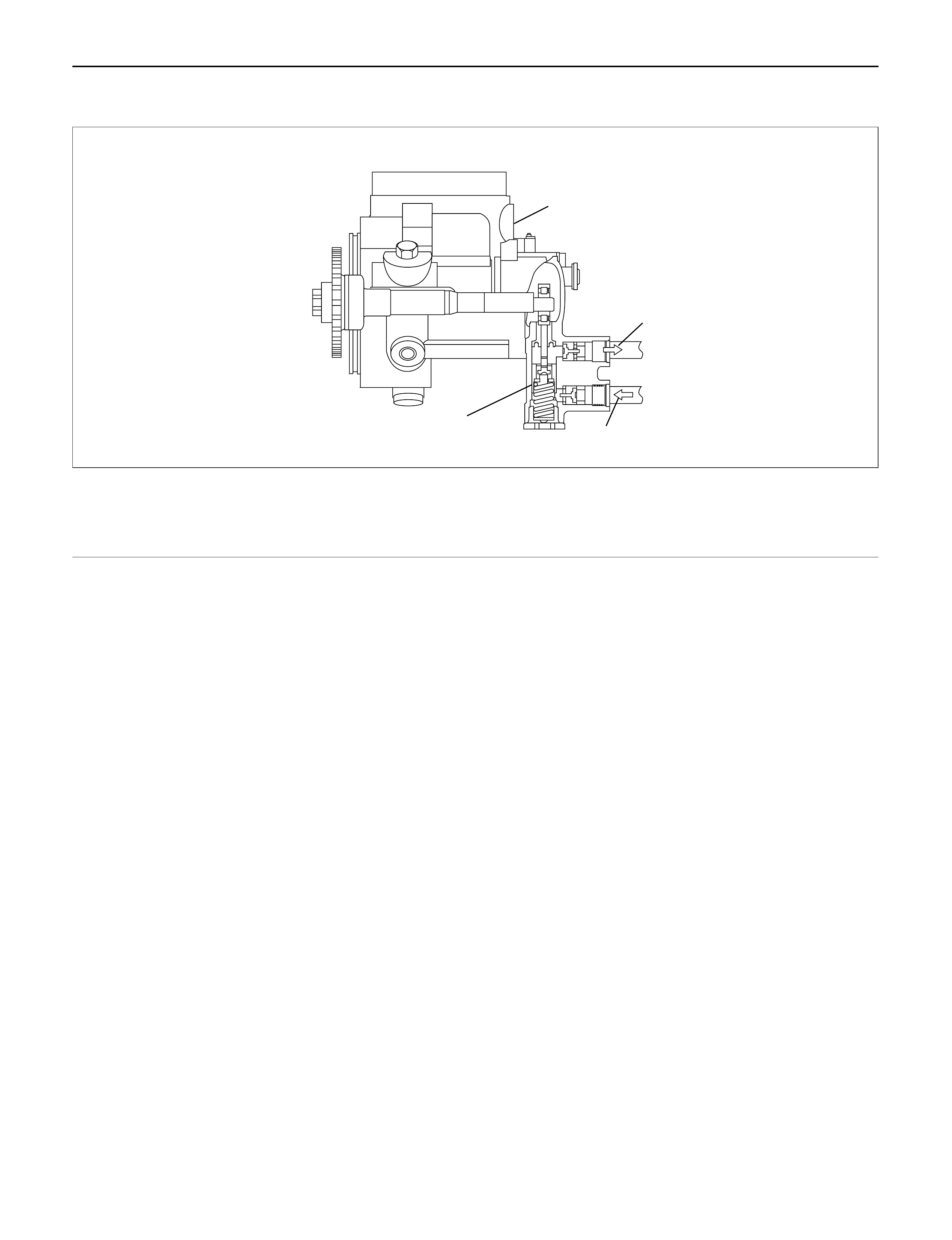
FUELPUMP
1
2
3
4
Legend
(1) High Pressure Oil Pump
(2)Outlet To Injector
(3)Inlet From Fuel Tank
(4) Fuel Pump
140RW041
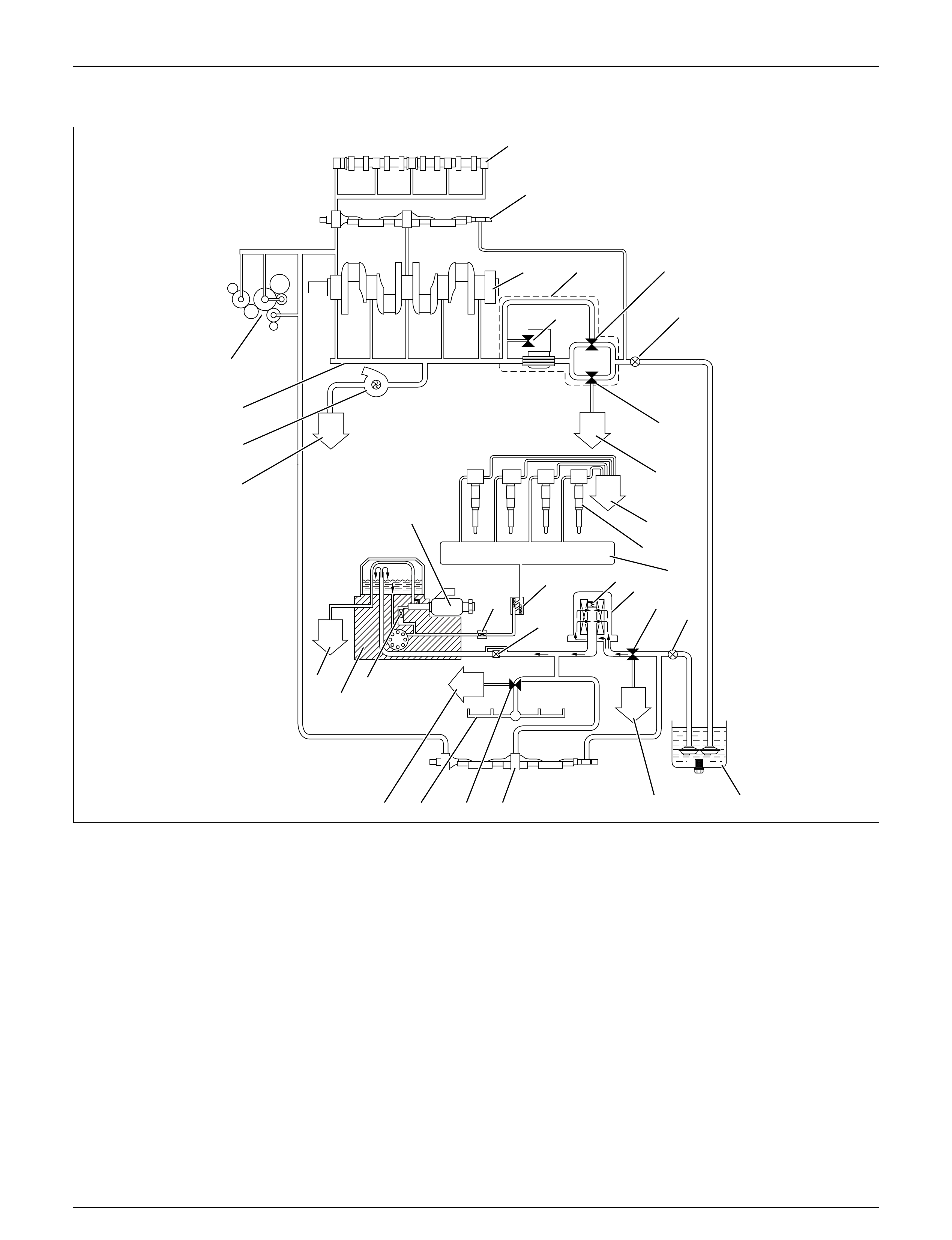
HIGH PRESSURE OIL PUMP, OIL FLOW
33
32
31
30
1
2
34
5
6
8
9
7
10
11 12
13 14
23
29
25
28 27 26
24
15 16
1718
19202122
Legend
(1) Camshaft
(2) Balance Shaft
(3) Crankshaft
(4) Oil Cooler and Oil Filter Assembly
(5) Oil Filter Relief Valve 98 Kpa (1 kg/cm2/14.2 Psi)
(6) Oil Cooler Relief Valve 245 Kpa (2.5 kg/cm2/
36 Psi)
(7) First Oil Pump
(8) Main Oil Relief Valve 588 Kpa (6 kg/cm2/ 85 Psi)
(9) To Oil Pan
(10) To Oil Pan
(11) Injector
(12) Oil Rail
(13) Sub Oil Filter Relief Valve 98 Kpa (1 kg/cm2/
14.2 Psi)
(14) Sub Oil Filter
(15) Relief Valve 588 Kpa (6 kg/cm2/ 85 Psi)
(16) Second Oil Pump
(17) Oil Pan
(18) To Oil Pan
(19) Balance Shaft
(20) Cooling Jet Relief Valve 245 Kpa (2.5 kg/cm2/
36 Psi)
(21) Cooling Jet
(22) To Oil Pan
(23) Two Way Check Valve
(24) Nipple Filter
(25) Edge Filter
(26) Edge Filter
(27) High Pressure Oil Pump Assembly
(28) To Oil Pan
(29) Pressure Control Valve
(30) To Oil Pan
(31) Turbocharger
(32) Oil Gallery
(33) Timing Gear Train
040RW018
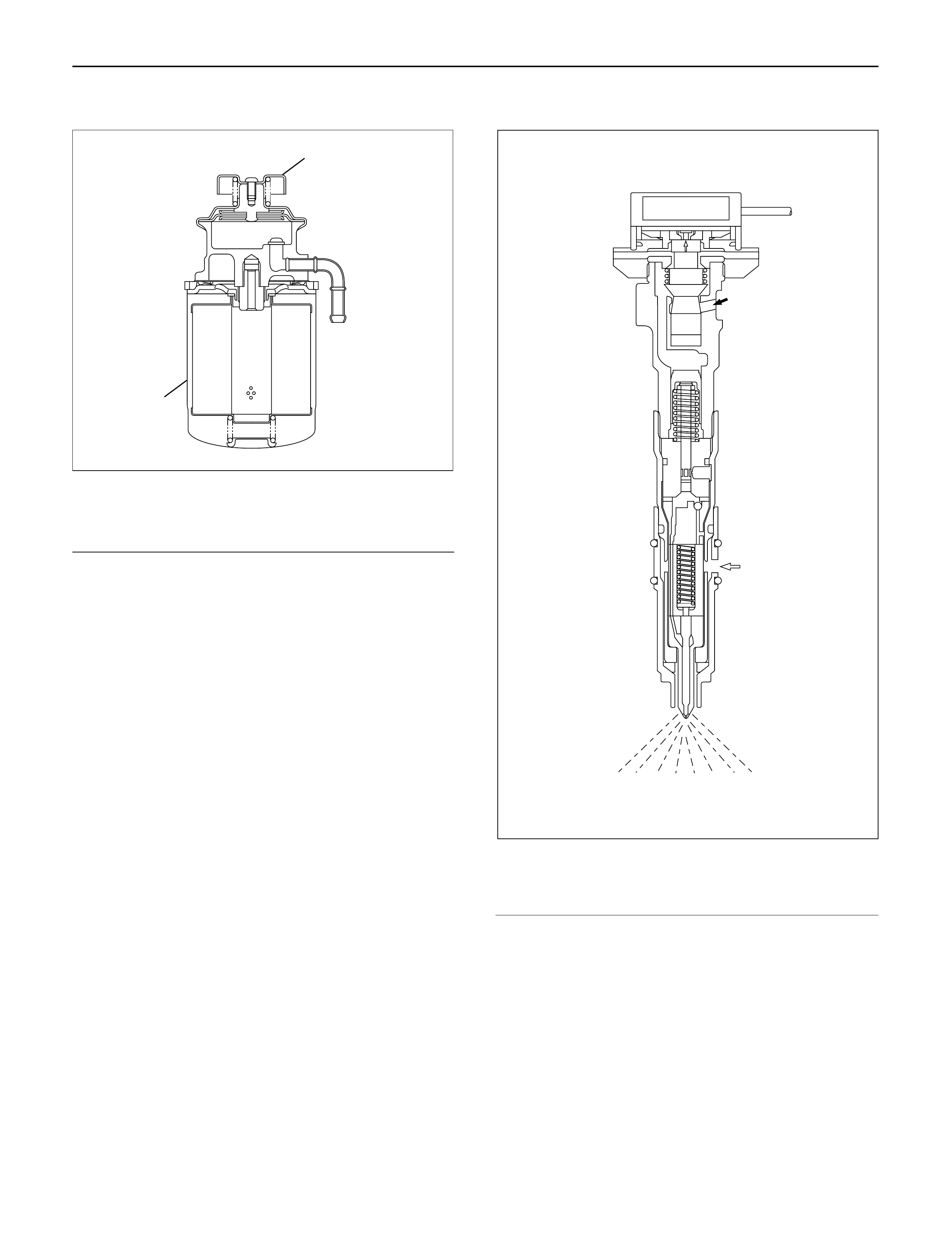
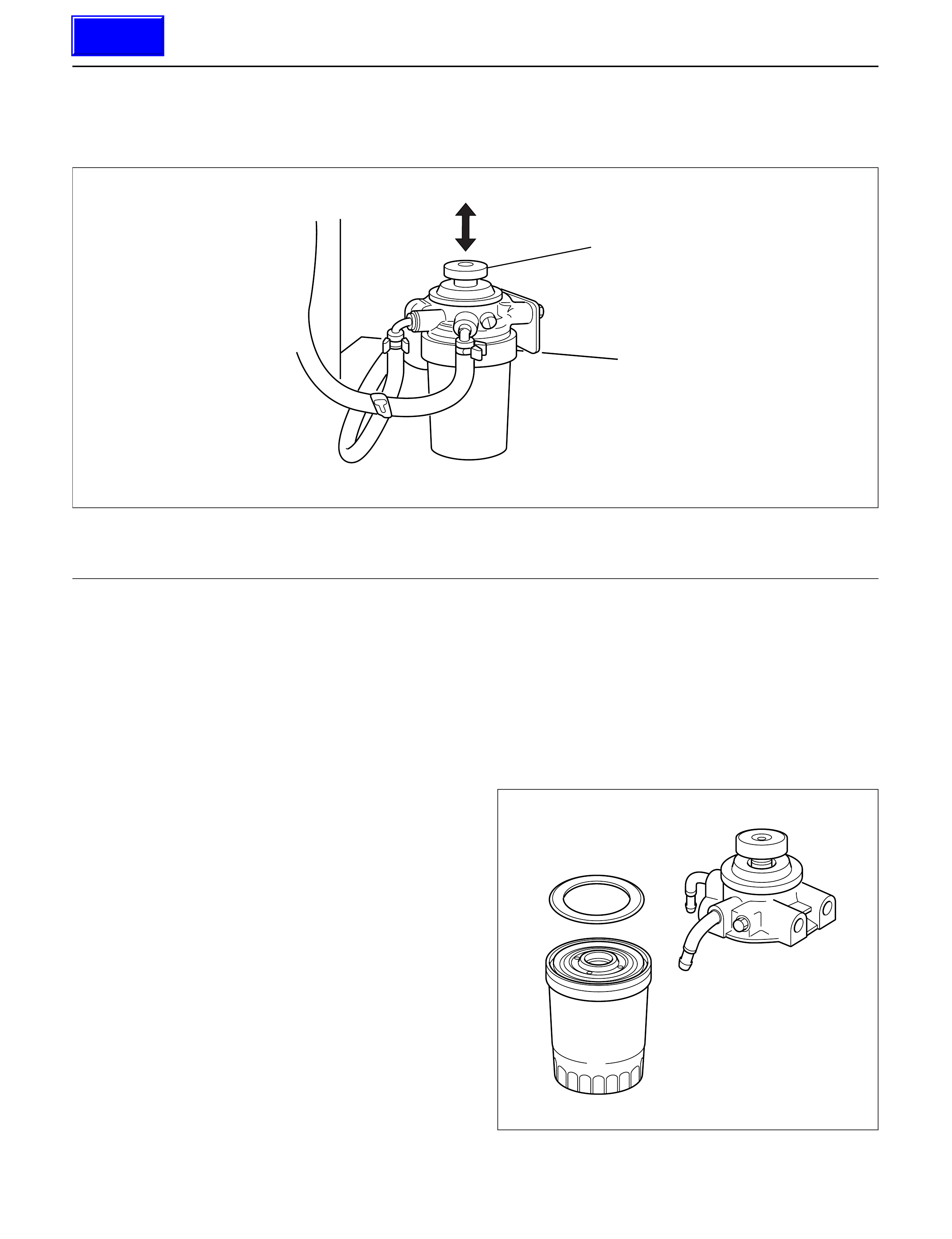
FUEL FILTER
Legend
(1) Priming Pump
(2) Fuel Filter Cartridge
A cartridge type fuel filter is used along with the piston
type fuel pump on the high pressure oil pump.
The fuel filter removes foreign material from the fuel
before it reaches the fuel pump.
Adiaphragm type priming pump is installed at the top of
the fuel filter. It is used during the air bleeding
procedures.
INJECT OR ASSEMBLY
Legend
(1) Oil Passage
(2) Fuel Passage
1.Construction
The fuel injector is comprised of the solenoid
section, hydraulic line, and fuel line. Fuel injection is
controlled by the continuity time signal and
continuity start timing signal sent by the ECM
(Electronic Control Module) to the solenoid.
2.Operation
1)The ECM detects engine operating conditions
from input signals, such as engine speed
accelerator throttle opening, and engine coolant
temperature, sending the optimal signals to the
solenoid.
1
2
041RW017
1
2
055RW018

2)With the current applied to the solenoid, a
poppet valve is opened by means of an
armature to let high-pressure engine oil into the
injector.
3) Under the oil pressure, the piston and plunger
are depressed to compress the fuel. The
pressure of the compressed fuel is increased
over the pressure of high-pressure engine oil by
the ratio (about 7 : 1) of piston top to plunger
base area.
4) The injection nozzle end needle is lifted under
the increased pressure of the fuel for fuel
injection.
5) When the ECM switches the current flow OFF,
the poppet valve closes, and the high-pressure
engine oil is exhausted from the injector.
ON-VEHICLE SERVICE
FUELFILTER ASSEMBLY
REMOVAL
1. Disconnect battery ground cable.
2.Fuel Filter cap
3. Fuel Hose
1) Disconnect fuel hose from filter body.
Plug the hose ends to prevent fuel spillage.
4. Remove the Bolt on Fuel Filter Bracket
5. Remove Fuel Filter Assembly
INSTALLATION
1. Install the fuel filter assembly
2. Tighten the Fuel Filter Bracket Fixing Bolt
3. Fuel Hose
1) Connect hoses to filter body.
4. Fuel Filler Cap
1) Connect the battery ground cable.
2) Feed fuel to the fuel pump by priming, and bleed
the air from fuel system.
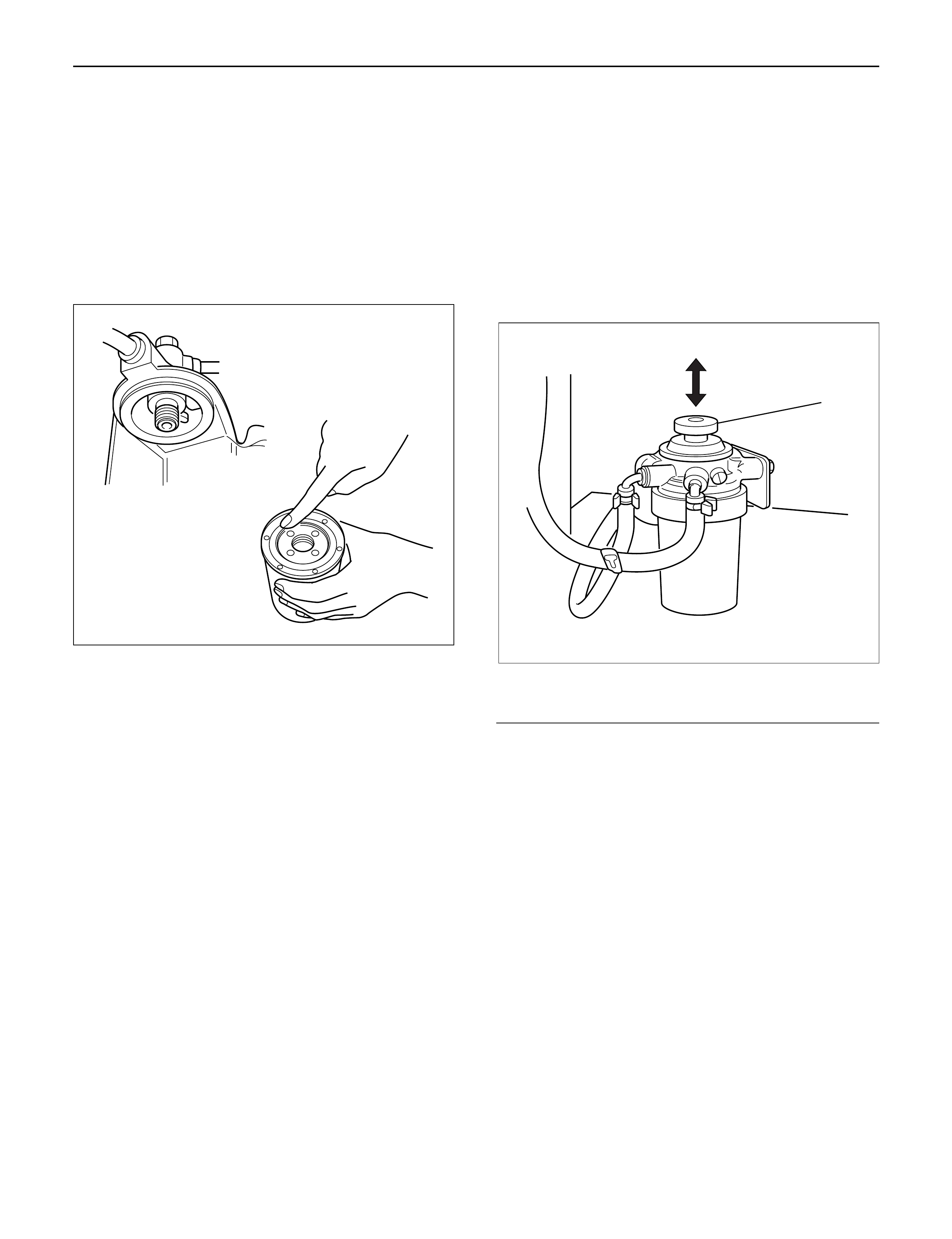
FUELFILTER CARTRIDGE
DISASSEMBLY
1. Drain fuel completely from the fuel filter.
2. Protect the filter body with cloth and lightly grip with
a vise.
3. Remove the cartridge using a filter wrench.
Filter wrench: 5-8840-0203-0
1
Legend
(1) Priming Pump
012RW111
012RW112
Techline
REASSEMBLY
1. Clean the cartridge mounting surface of the filter
body so that the cartridge can be secured.
Apply engine oil thinly to new cartridge O-ring.
2. To facilitate bleeding, fill the new cartridge with light
oil.
3. Tighten the cartridge until O-ring comes in contact
with the seal, taking care not to spill the light oil.
4. Retighten 1/3 – 2/3 using a filter wrench.
Filter wrench: 5-8840-0203-0
Bleeding
1. Loosen air bleeding plug.
2. Operate priming pump to bleed the air in the fuel
line.
3. Operate the priming pump until the fuel is overflow
from air bleeding plug.
4. Tighten the air bleeding plug.
5. Start the engine, and if it is not started in 10
seconds or less, repeat the bleeding steps.
6. Make sure of no fuel leakage, and tighten the
priming pump.
Legend
(1) Priming Pump
NOTE: In comparison with the conventional engine,
the capacity of fuel passage in the 4JX1 engine is
larger. It takes the priming pump more time to fill the
engine with fuel.
012RW078
1
012RW111
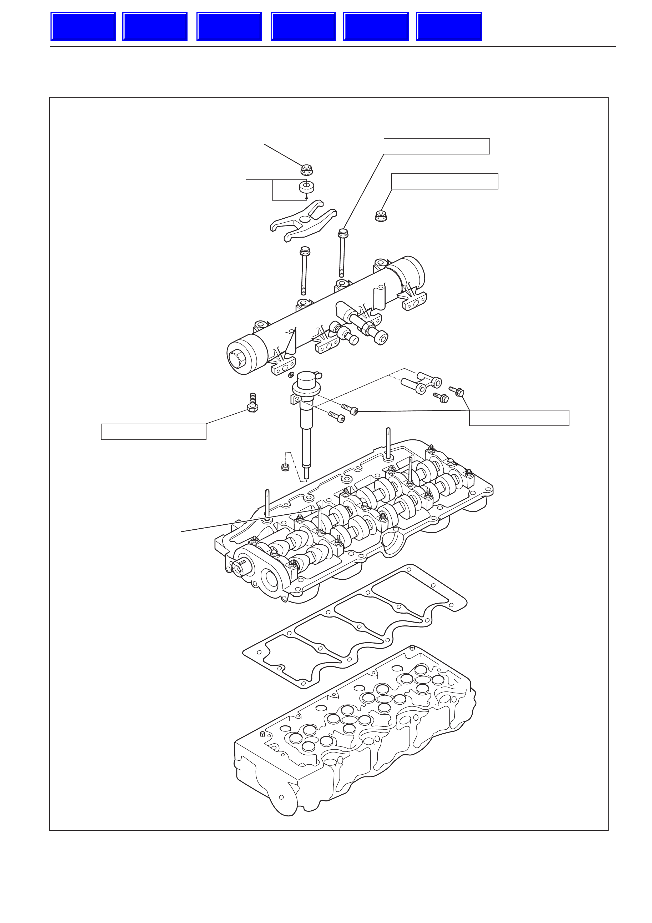
INJECTOR
N.m (kg m/lb ft)
20N.m (2.0kg.m/14 lb.ft)
7N.m (0.7kg.m/61 lb.in)
20N.m (2.0kg.m/14 lb.ft)
Recheck tightening torque
after tightening the oil rail
Apply engine oil to the
stud bolt threads
Tighten 30N.m (3.1kg.m/22lb.ft)
Loosen then tighten again to
25N.m (2.5kg.m/18 lb.ft)
Apply engine oil
to both sides
25N.m (2.5kg.m/18ft.lb) Without
spacer type
E06R200027
With
spacer type
Techline
Techline
Techline
Techline
Techline
Techline
REMOVAL
Prior to removal, be sure to confirm and record the
group code of the injector installed using Tech2.
1.Disconnect battery ground cable.
2.Remove air cleaner cover and air duct.
3.Remove intercooler.
Refer to “Intercooler” in this manual.
4.Remove PCV hose and pipe.
5.Remove cylinder head noise insulator cover.
6.Remove high pressure oil pipe.
CAUTION:
1) Sleeve nut should be loosened with cloth tied
around to prevent oil from spurting due to the
remaining pressure.
2) High oil pressure pipe should be disconnected
with cloth tied around the intake manifold glow
plug to prevent oil from flowing out of the oil
rail.
7. Loosen eye bolt of fuel pipe at fuel pump side.
NOTE: Cloth should be put around the loosened eye
bolt to prevent fuel from flowing out.
8. Remove fuel return hose at chassis side.
9. Remove PCV hose to cylinder head cover.
10. Remove cylinder head cover.
11. Drain the oil from oil rail assembly.
NOTE: Do not drop O-ring
12. Record the grade code of injector for each cylinder
that is indicated on the upper portion of injector.
There are nine kinds of grade code available, one
alphabet letter and one numeral letter.
Grade code
Legend
(1) Part Number
(2) Category Number (Grade code)
(3) Serial Number
(4) Bar Code
13. Remove harness connector from each injector.
14. Loosen nuts and bolts for oil rail.
15. Remove injector fixing bolts.
16. Remove injector clamp.
17. Remove injector assembly.
INSTALLATION
1. Install oil rail, tighten temporarily
2. Install injector assembly.
NOTE:
1) Do not forget to install O-ring between injector and
oil rail.
2) Use new O-ring
3) Clean O-ring groove and fitting surface of parts.
4) Apply engine oil to O-ring.
3. Install injector fixing bolts, tighten temporarily.
4. Install injector clamp, tighten nut temporarily.
· Apply engine oil to washer both side.
5. Tighten injector fixing bolts to the specified torque.
Torque: 7 N·m (0.7 kg·m / 61 lb in)
6. Tighten injector clamp nut to the specified torque
with special method.
Torque: 30 N·m (3.1 kg·m / 22 lb ft) then loosen a
time again tighten as following torque.
Torque: 25 N·m (2.5 kg·m / 18 lb ft)
7. Tighten oil rail to the specified torque.
Torque: 20 N·m (2.0 kg·m / 14 lb ft)
1
4
3
2
055RW00001
Category number
A– 1
A– 2
A– 3
B – 1
B – 2
B – 3
C – 1
C – 2
C – 3
8.Install injector harness assembly, reconnect
harness connecter to injector.
9.Record the identification marking of injector for
each cylinder that is indicated on the upper portion
of injector.
Legend
(1)Part Number
(2)Category Number (Grade code)
(3)Serial Number
(4)Bar Code
10.Install cylinder head assembly.
Refer to “Cylinder Head” in this manual.
11.Fill with about 300cc of engine oil from the high
pressure oil pipe installation port of the oil rail using
an oil filler.
If assembled without filling the oil rail with oil, the
time for engine starting will be longer.
12.Immediately install high pressure oil pipe and
tighten to specified torque.
Torque: 78 N·m (8.0 kg·m / 58 lb ft)
13.Install cylinder head noise insulator cover.
Refer to “Cylinder Head” in this manual.
14.Install intercooler assembly.
Refer to “Intercooler” in this manual.
15.Install air cleaner cover and air duct.
16.Use TECH2 to rewrite injector data to ECM.
For rewriting method refer to section “Data
Programming in Case of ECM Change” of section
6E 4JX1 engine driveability and emissions in this
manual.
NOTE:
1) On completion of servicing, bleed air from the
engine inside fuel passage by means of the priming
pump. (The priming pump should be operated more
times than in the case of conventional engines.)
2) As air is in the oil rail, it takes more time to start the
engine. Rough idling may occur while the air is
being bled completely after engine start, but it does
not indicate trouble.
The air will be bled and normal engine status will be
reached while the vehicle is driven for about 5 km
or engine is operated for about 5 minutes at 1500 to
2000 rpm.
3) The injector spare part will be provided for group
number B1, B2 and B3 only.
Injector Grade code Programming
(Injector Change)
In case of an injector change, the injector grade code
(category number) must be programmed by Tech-2.
Programming Procedure
1. Connect the Tech-2 to the vehicle DLC.
2. Turn the starter switch to the “ON” position.
3. Select the “Diagnosis” from the Main menu.
4. Select the “Programming” from the Application
menu.
1
4
3
2
055RW00001
F0 :
F1 :
F2 :
F3 :
F4 :
035RW00002

5. Select “Programming Trim Date” from
Programming menu.
6. Select the injector change from Programming Trim
Date menu.
7. Select the cylinder number which changed injector.
8. Appoint and select the grade code (Category
number) of injector.
9. Confirm the completion of injector programming.
Note; The injector grade code (category number) is
indicated on the new (service part) injector.
Injector 1
Injector 4
Injector 3
Injector 1
Programming Trim Data
Select cylinder
Injector 2
(W) 1998 (UE) Rodeo/Amigo,Wizard
Electronic System 3.0L L4 4JX1
035RW00003
Injector 1
Programming Trim Data
Do you program trim data in
this cylinder
(W) 1998 (UE) Rodeo/Amigo,Wizard
Electronic System 3.0L L4 4JX1
YesNo
035RW00004
1Category A1
(W) 1998 (UE) Rodeo/Amigo,Wizard
3.0L L4 4JX1
035RW00005
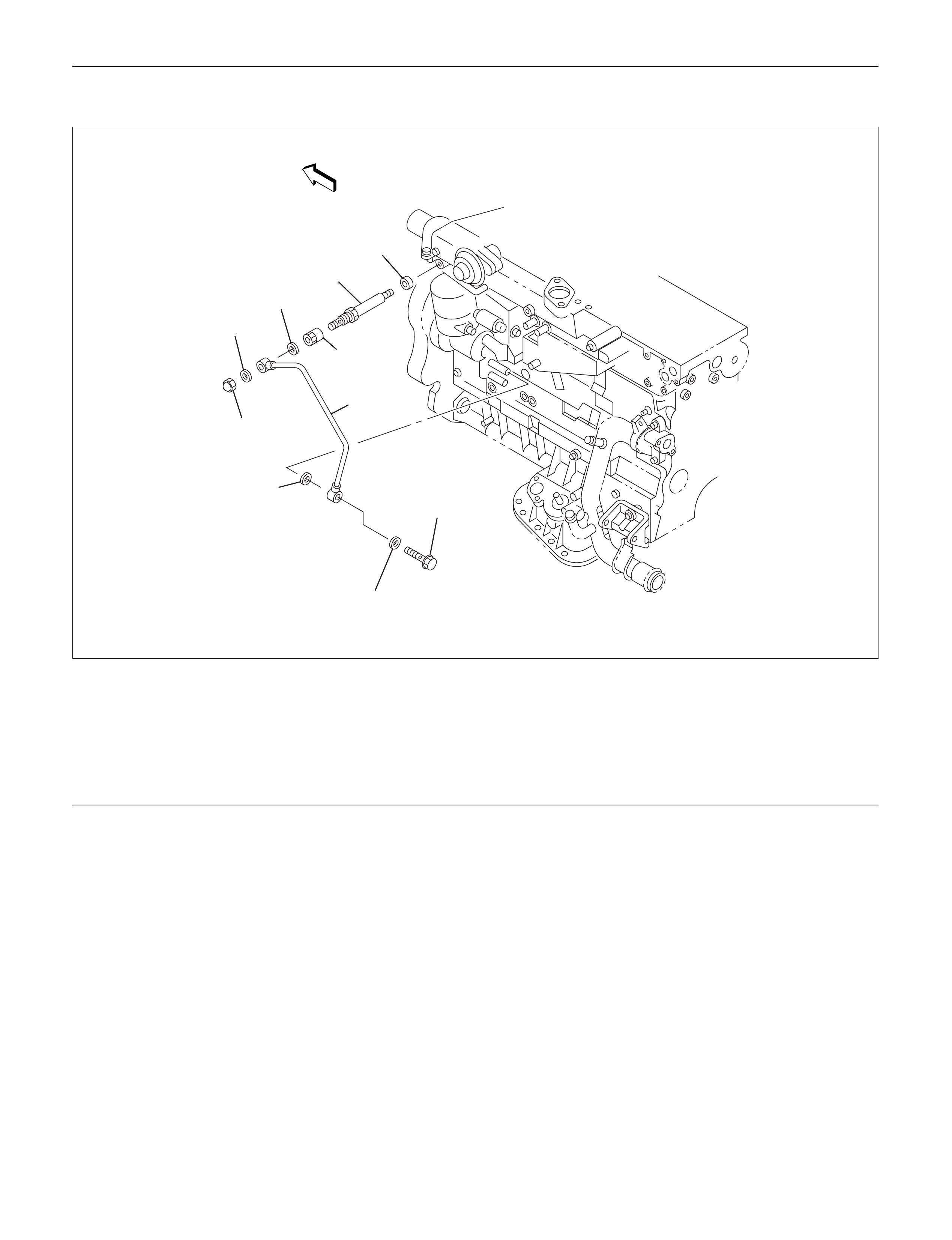
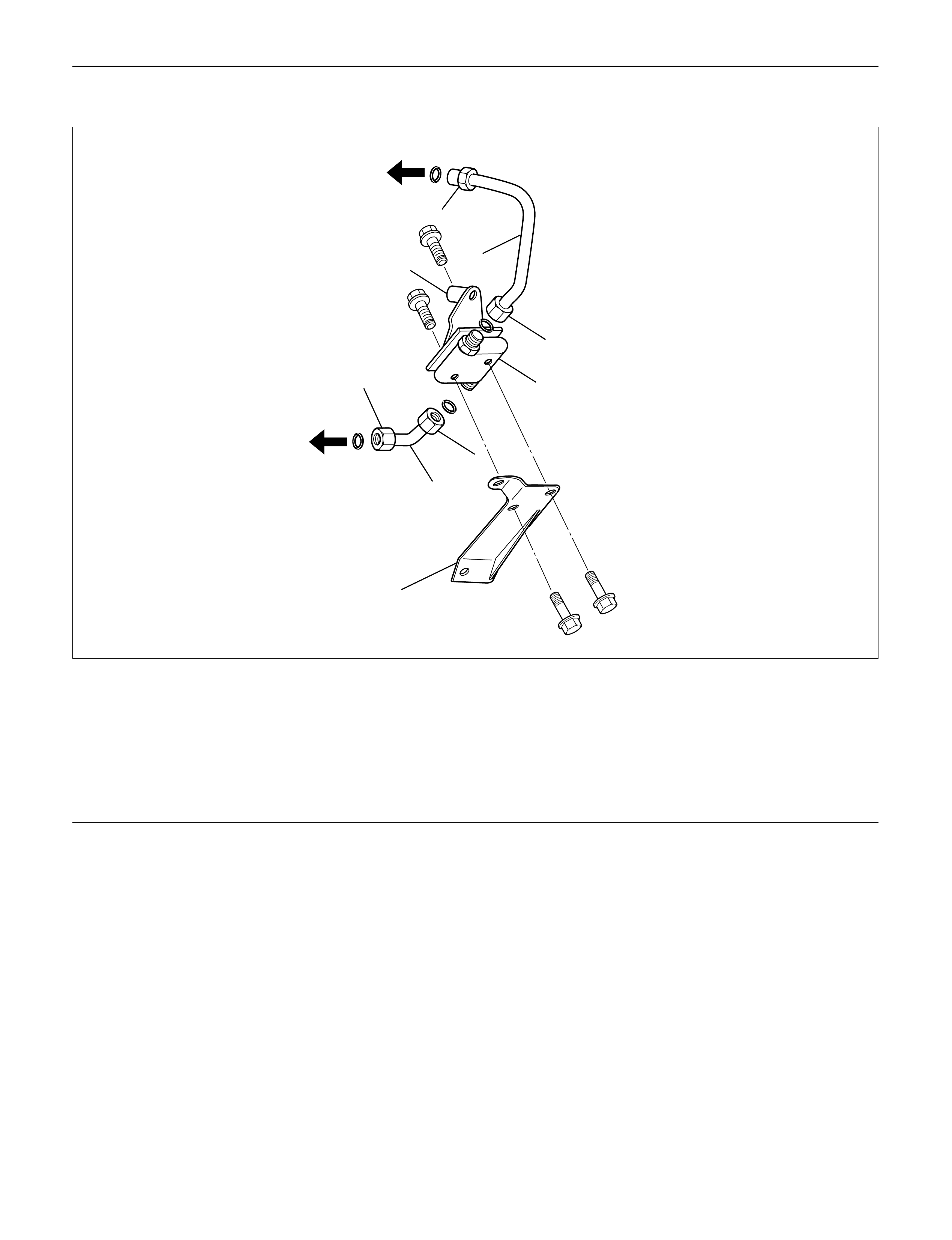
FUELPUMPPIPE
6
2
3
10
9
8
5
4
7
1
Legend
(1) Cap Nut
(2) Gasket
(3) Gasket
(4) Pipe Nut
(5) Adapter
(6) Gasket
(7) Fuel Pump Pipe
(8) Eye Bolt
(9) Gasket
(10) Gasket
040R200002
REMOVAL
1. Remove eye bolt.
2. Remove cap nut.
NOTE: The eye bolt and cap nut should be
disconnected with cloth tied around them to prevent
flowing out of fuel.
3. Remove fuel pump pipe.
4. Remove pipe nut.
5. Remove adapter.
INSTALLATION
1. Apply engine oil to the thread, then install adapter
with new gasket.
Torque : 13 N·m (1.3 kg·m/113 lb in)
NOTE: Be careful not to enter the foreign material.
2. Apply engine oil to the thread, then install pipe nut.
Torque : 14 N·m (1.4 kg·m/122 lb in)
NOTE: Do not apply oil to cap nut side.
3. Install fuel pump pipe, new gaskets and cap nut to
adapter temporarily. Do not tighten the cap nut.
4. Install eye bolt with new gasket then tighten to
specified torque.
Torque : 30 N·m (3.1 kg·m/22 lb ft)

NOTE:
1) Do not apply oil to the eye bolt.
2) Do not bend the fuel pump pipe.
5. Tifhten cap nut to specified torque.
Torque : 13 N·m (1.3 kg·m/113 lb in)
NOTE: Do not apply oil to the cap nut.
6. Start the engine, check that the fuel leakage is not
found.
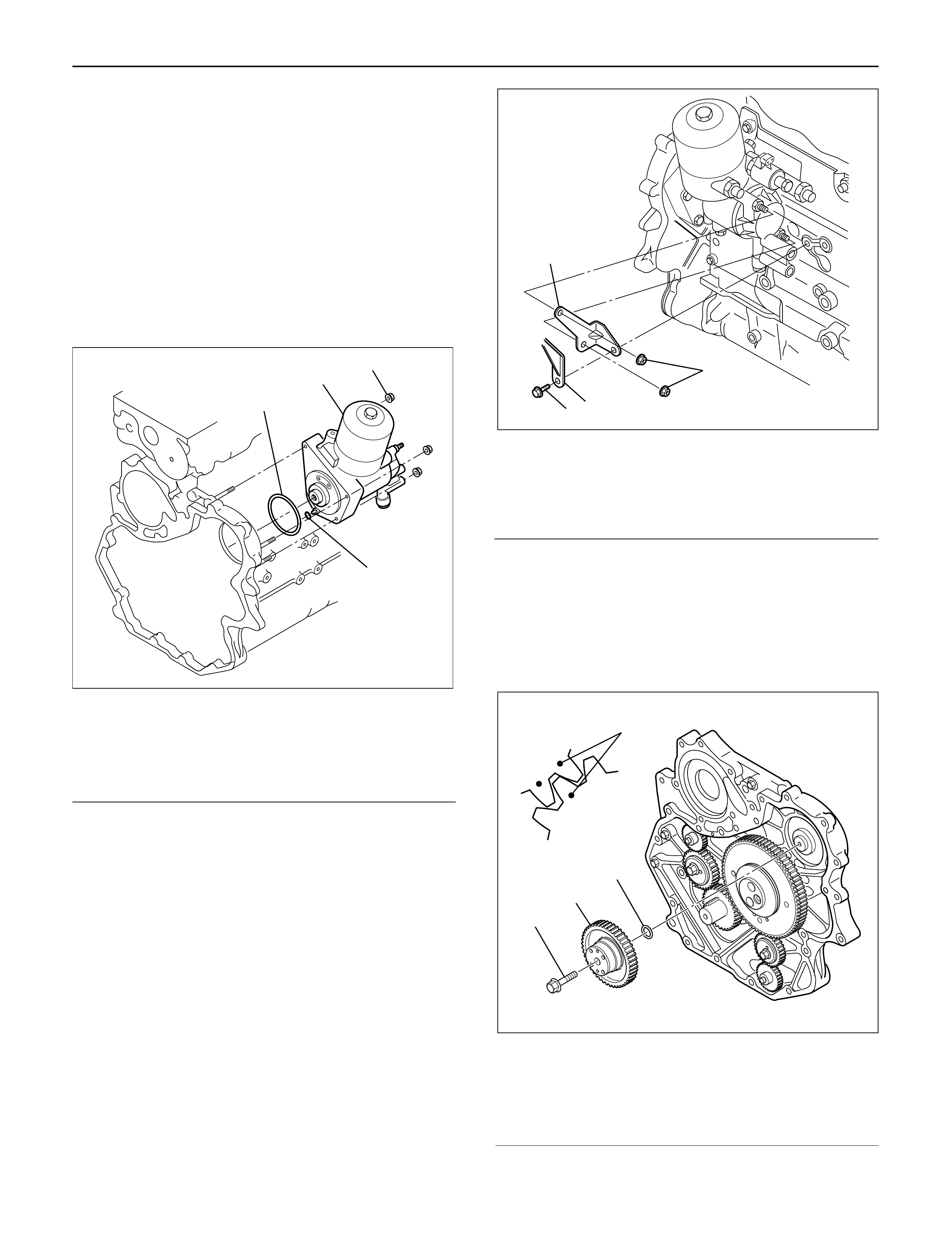
HIGH PRESSURE OILPUMP
REMOVAL
1. Disconnect battery ground cable.
2. Remove air cleaner cover and air duct
3. Intercooler assembly
Refer to “Intercooler” in this manual.
4. Remove high pressure oil pipe
5. Timing belt cover
Disconnect CMP sensor cable.
Remove CMP sensor bracket.
6. Tensioner
7. Timing Belt
8. Remove high pressure oil pump timing pulley
9. Remove crankshaft damper pulley
10. Remove timing gear case cover
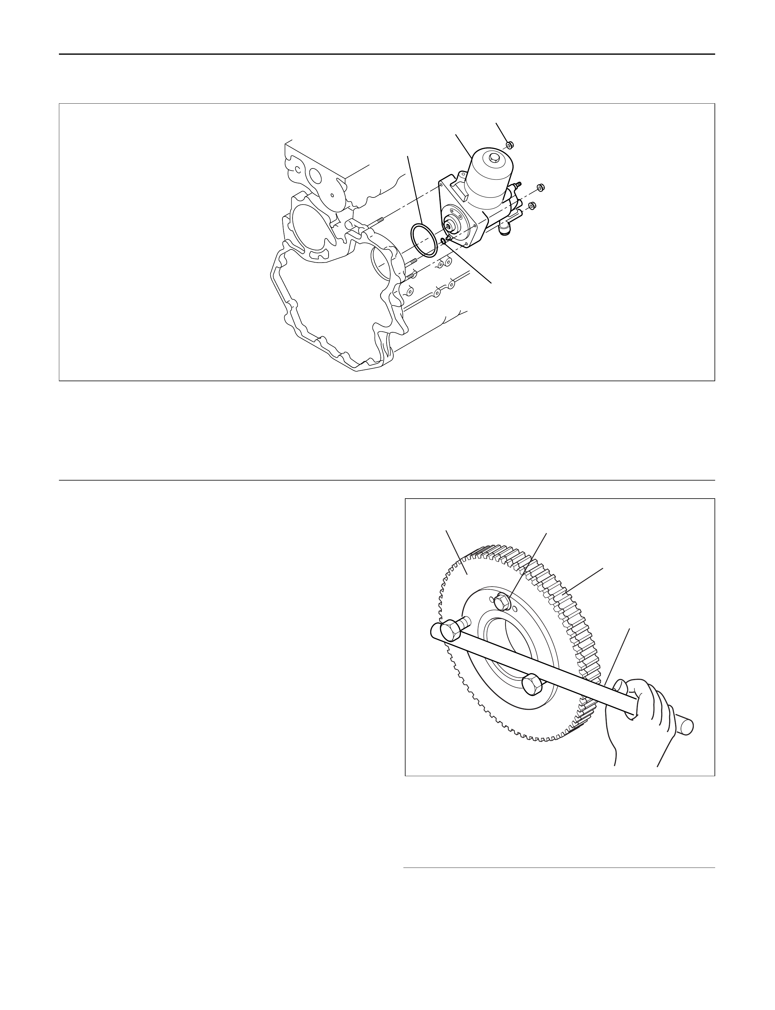
11. Remove idle gear A
Before removing idle gear A, set two bolts to the
sub gear of idle gear A and turn it to align the teeth
of idle gear A main gear.
Then lock them by bolts as shown in the illustration. Legend
(1) Idle gear A sub gear
(2) Idle gear A main gear
(3) Bar
(4) Lock bolt
1
2
4
3
Legend
(1) O-Ring
(2) High Pressure Oil Pump Assembly
(3) Nut
(4) O-Ring
040RW007
4
1
2
3
014RW177
12. Remove high pressure oil pump
13. Remove high pressure oil pump assembly
Legend
(1) O-ring
(2) High pressure oil pump
(3) Nut
(4) O-ring
1
2
4
3
040RW007
INSPECTION AND REPAIR
The high pressure oil pump is made precisely,
therefore, disassembly is not recommended.
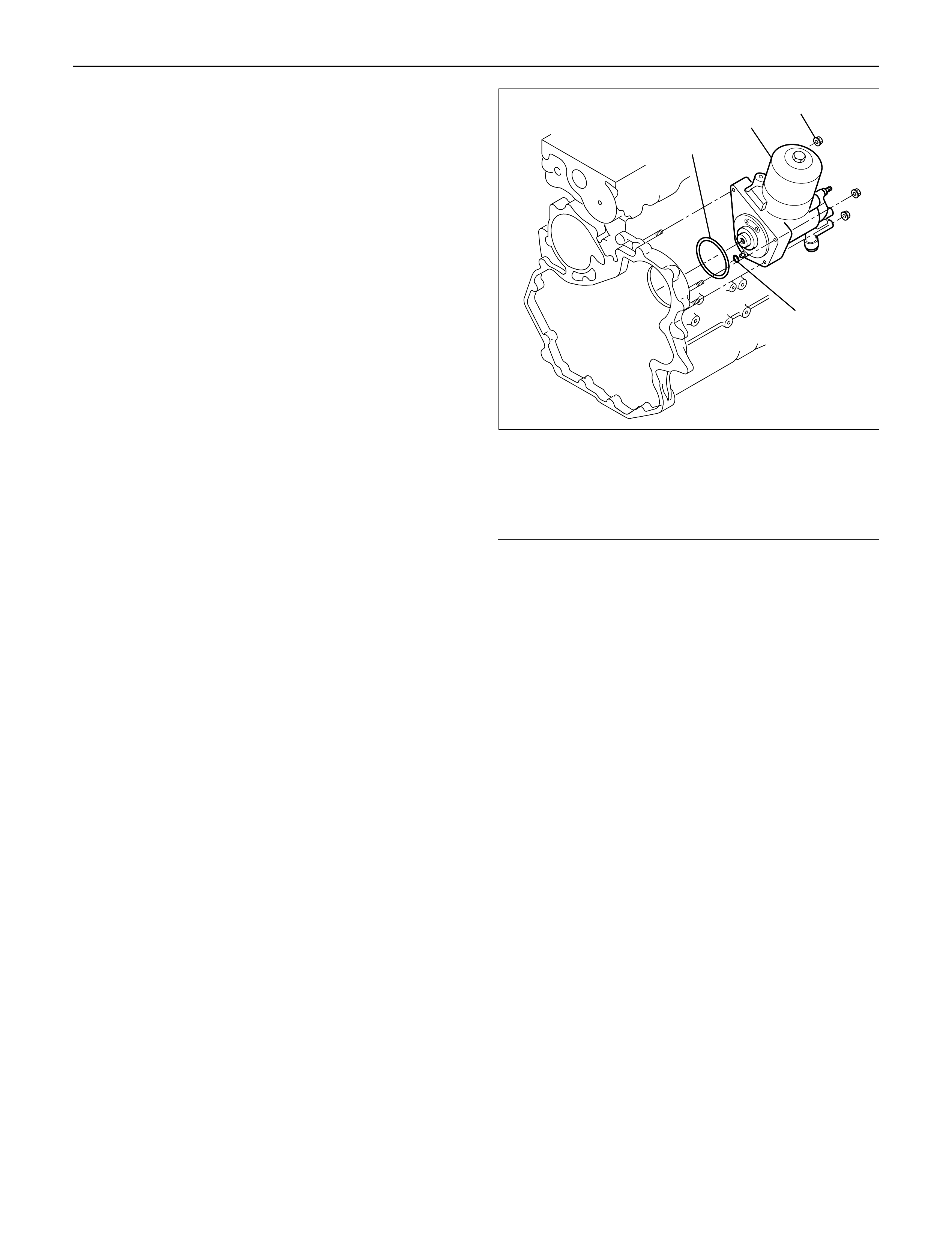
INSTALLATION
1. Set O-ring to high pressure oil pump assembly.
Apply Loctite No. 262 to the stud bolts.
Install the pump assembly into the rear of timing
gear case.
Tighten nut to specified torque.
Torque: 20 N·m (2.0 kg·m/14 lb ft)
Legend
(1) O-ring
(2) High Pressure Oil Pump Assembly
(3) Nuts
(4) O-ring
2. Tighten high pressure oil pump assembly bracket
together with two way valve bracket.
Torque: 27 N·m (2.8 kg·m/20 lb ft)
Legend
(1) High Pressure Oil Pump Assembly
(2) Nut
(3) Two Way Valve Bracket
(4) Bolt
3. Install the pump gear to align timing mark with idle
gear A.
Tighten high pressure pump gear fixing bolt to the
specified torque.
Apply engine oil to thread and seat of bolt.
Torque: 75 N·m (7.6 kg·m/55 lb ft)
Legend
(1) O-ring
(2) Pump Gear
(3) Bolt
(4) Timing Mark
1
2
4
3
040RW007
2
3
4
1
040RW006
4
GEAR:O/PUMP
IDLE GEAR A
1
2
3
040RW005

4.Remove lock bolt of idle gear A.
5.Install timing gear case cover.
Refer to “Timing gear” in this manual.
6.Install front plate.
Torque: 20 N·m (2.0 kg·m/14 lb ft)
7.Install timing pulley of high pressure oil pump.
Torque: 10 N·m (1.0 kg·m/87 lb in)
8.Install timing belt and tighten timing belt tensioner
assembly.
Refer to “Cylinder head” in this manual.
Legend
(1)Align Mark
(2)Camshaft Pulley
(3)Timing Belt
(4)High Pressure Oil Pump Pulley
(5)Tensioner Bolt B
(6)Tensioner Assembly
(7)Tensioner Bolt A
(8)Tensioner Spring
9.Install CMPsensor bracket.
Torque: 20 N·m (2.0 kg·m/14 lb ft)
10.Connect CMPsensor cable.
11.Install timing belt cover.
Torque: 9 N·m (0.9 kg·m/78 lb in)
12.Fill with about 300 cc of engine oil from the high
pressure oil pipe installation port of the oil rail using
an oil filler.
If assembled without filling the oil rail with oil, the
time for engine starting will be longer.
13.Immediately install high pressure oil pipe and
tighten to specified torque.
NOTE:
1)Use new O-ring.
2)Clean O-ring groove and fitting surface of parts.
3)Apply engine oil to O-ring.
Torque: 78 N·m (8.0 kg·m/58 lb ft)
14.Install the crankshaft damper pulley with specified
torque.
Torque: 216 N·m (22 kg·m/159 lb ft)
15.Install the intercooler assembly.
Refer to “Intercooler” in this manual.
16. Install air cleaner cover and air duct.
1
2
3
8
6
7
4
5
F06R200006
HIGH PRESSURE OILPIPE INSTALLATION
1. Install upper bracket to two way valve, tighten them
temporarily.
2. Install pipe A to two way valve, tighten pipe A
temporarily with union nut D.
3. Install two way valve assembly to cylinder block,
tighgten with union nut C temporarily.
4. Install pipe B to two way valve, tighten union nut E
and union nut F temporarily.
5. Tighten upper bracket to specified torque.
Torque : 20 N·m (2.0 kg·m/14 lb ft)
6. Tighten union nut in the following order, union nut
C, D, F, and E to the specified torque.
Torque : 78 N·m (8.0 kg·m/58 lb ft)
7. Tighten lower bracket to the specified torque.
Torque : 20 N·m (2.0 kg·m/14 lb ft)
NOTE: Wash inside pipe, inside union nut and O-ring
seal surface to remove engine oil and foreign materials.
6
5
7
9
8
11
4
1
2
3
10
Legend
(1) Union Nut F
(2) Pipe B
(3) Union Nut E
(4) Upper Bracket
(5) Two Way Valve
(6) Union Nut D
(7) Pipe A
(8) Union Nut C
(9) Lower Bracket
(10) To Oil Rail
(11) To High Pressure Oil Pump
052R200001
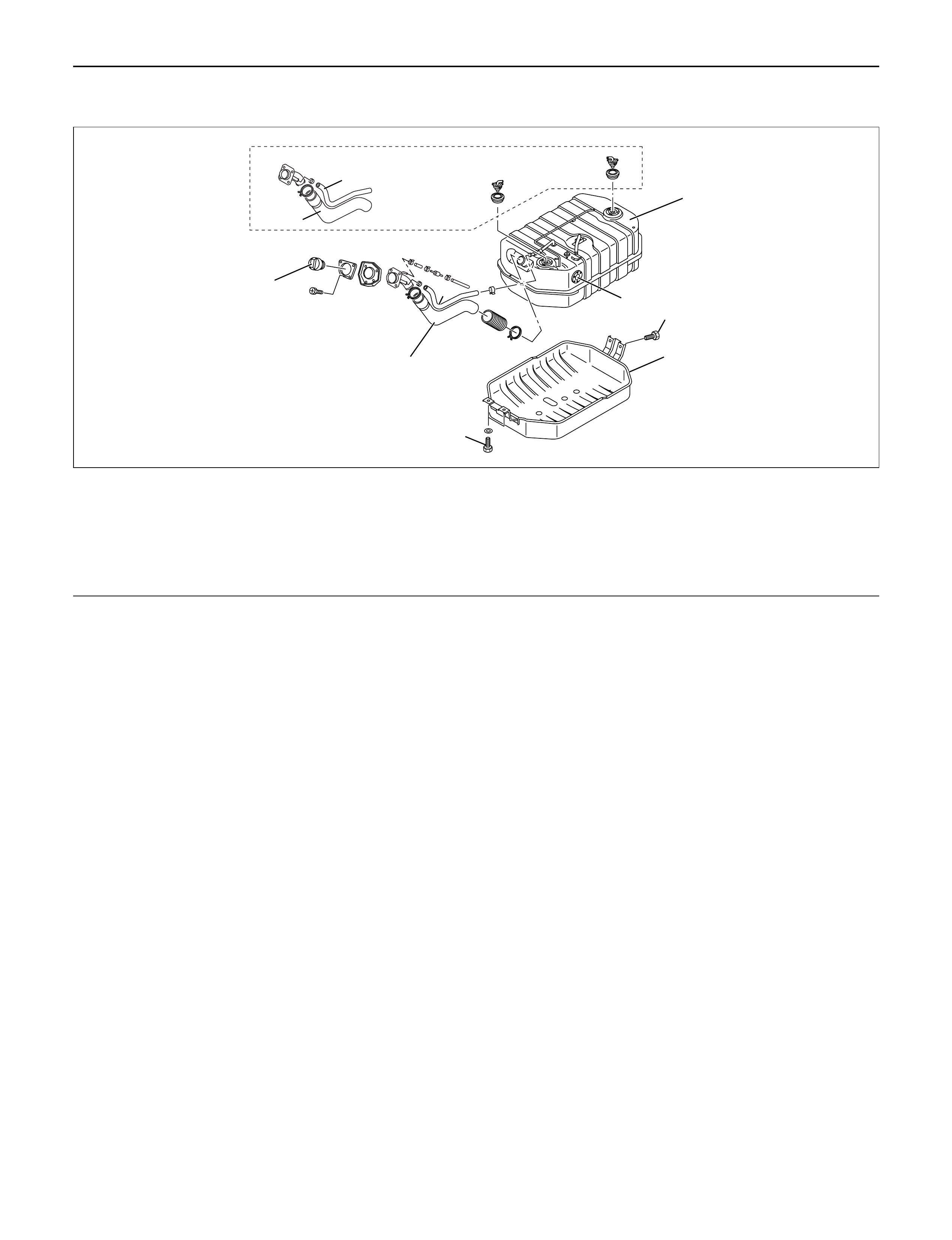
FUELTANK
REMOVAL
1. Disconnect battery ground cable.
2. Remove fuel filler cap.
3. Drain fuel.
After drain the fuel tighten the drain plug with
specified torque.
Torque : 20 N·m (2.0 kg·m/14 lb ft)
4. Remove fuel filler hose and let air pull off hose.
5. Remove breather hose.
6. Remove fuel feed hose and fuel return hose.
7. Disconnect harness connector from fuel gauge unit.
8. Remove under cover.
9. Remove fuel tank assembly.
INSTALLATION
1. Fuel tank assembly.
1) Place a flange on right side of tank on the
bracket.
2) Install a flange to left side of the bracket from the
bottom, and tighten bolts to the specified torque.
Torque : 36 N·m (3.7 kg·m/27 lb ft)
2. Install fuel hose and fuel return hose.
3. Install the breather hose.
4. Reconnect harness connector to fuel gauge unit.
5. Install under cover.
6. Install fuel filler hose and let air pull off hose.
7. Fill fuel tank with fuel and tighten filler cap.
8. Reconnect battery ground cable.
1
2
4
8
6
7
8
MY2003 Euro-3
6
5
3
Legend
(1) Fuel Tank Assembly
(2) Gauge Unit
(3) Bolt
(4) Under Cover
(5) Bolt
(6) Fuel Filler Hose
(7) Fuel Filler Cap
(8) Breather Hose
140R200032
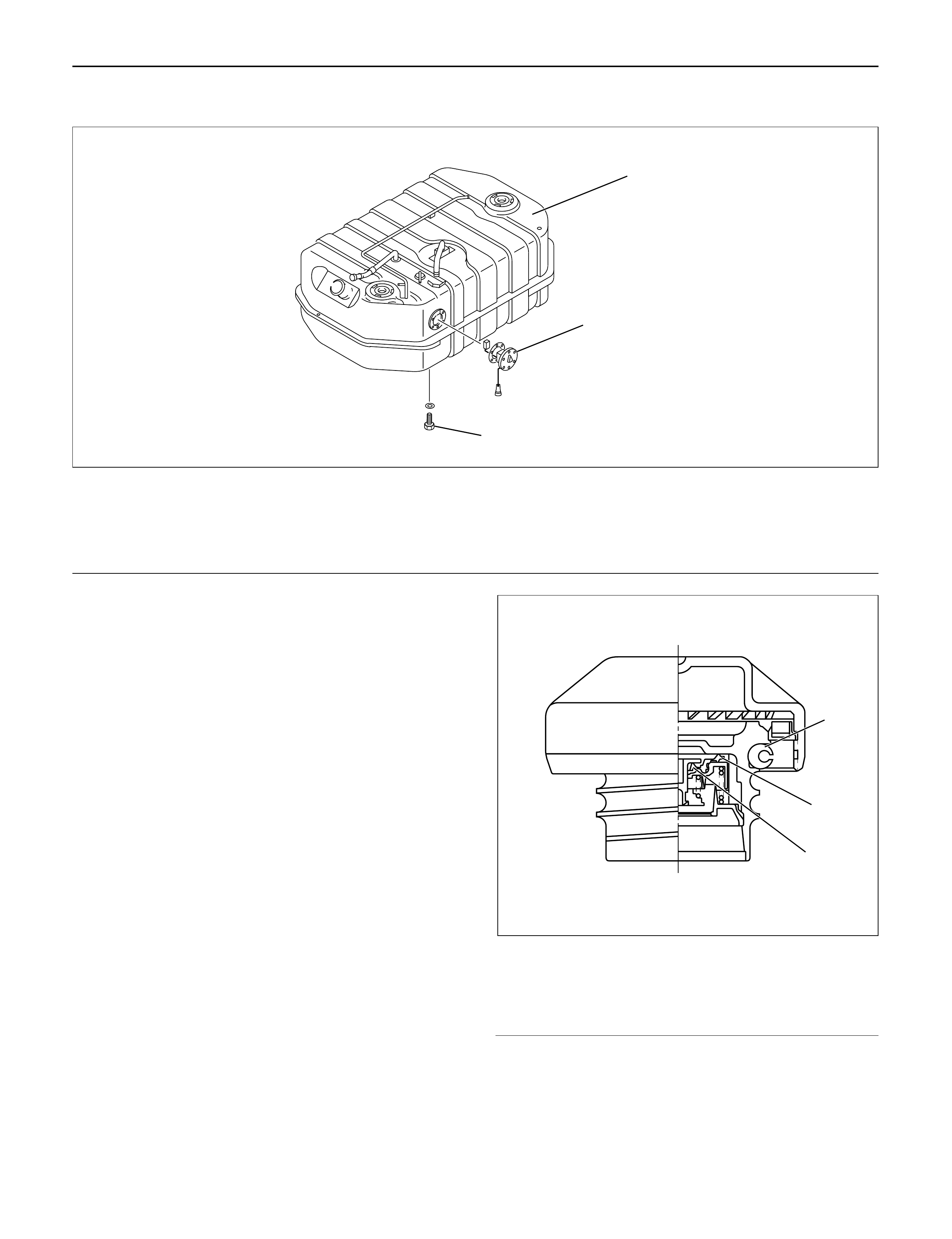
FUELGAUGE UNIT
1
2
3
140R200033
REMOVAL
1. Disconnect battery ground cable.
2. Loosen fuel filler cap.
3. Drain fuel.
After drain the fuel tighten the drain plug with
specified torque.
Torque : 20 N·m (2.0 kg·m/14 lb ft)
4. Disconnect harness connector from fuel gauge unit.
5. Fuel Gauge Unit
1) Remove the fixing screws, then the fuel gauge
unit.
INSTALLATION
1. Fuel Gauge Unit
2. Connect the harness connector to the fuel gage
unit.
3. Fill the tank with fuel and tighten fuel filler cap.
4. Connect battery ground cable.
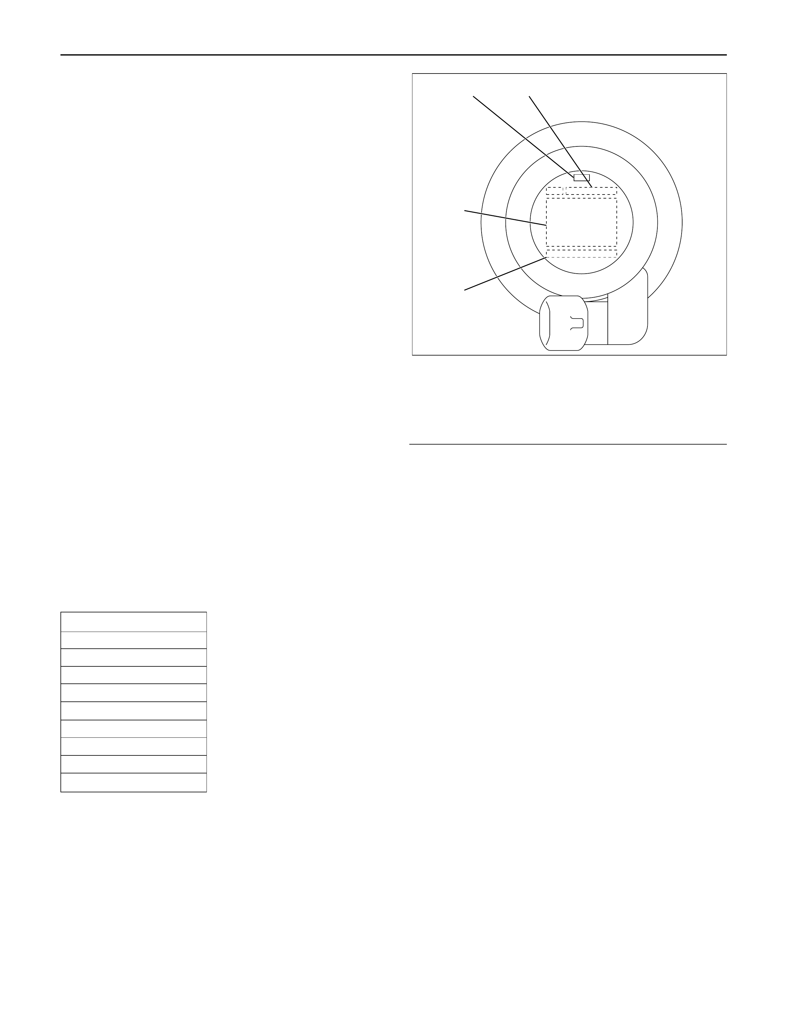
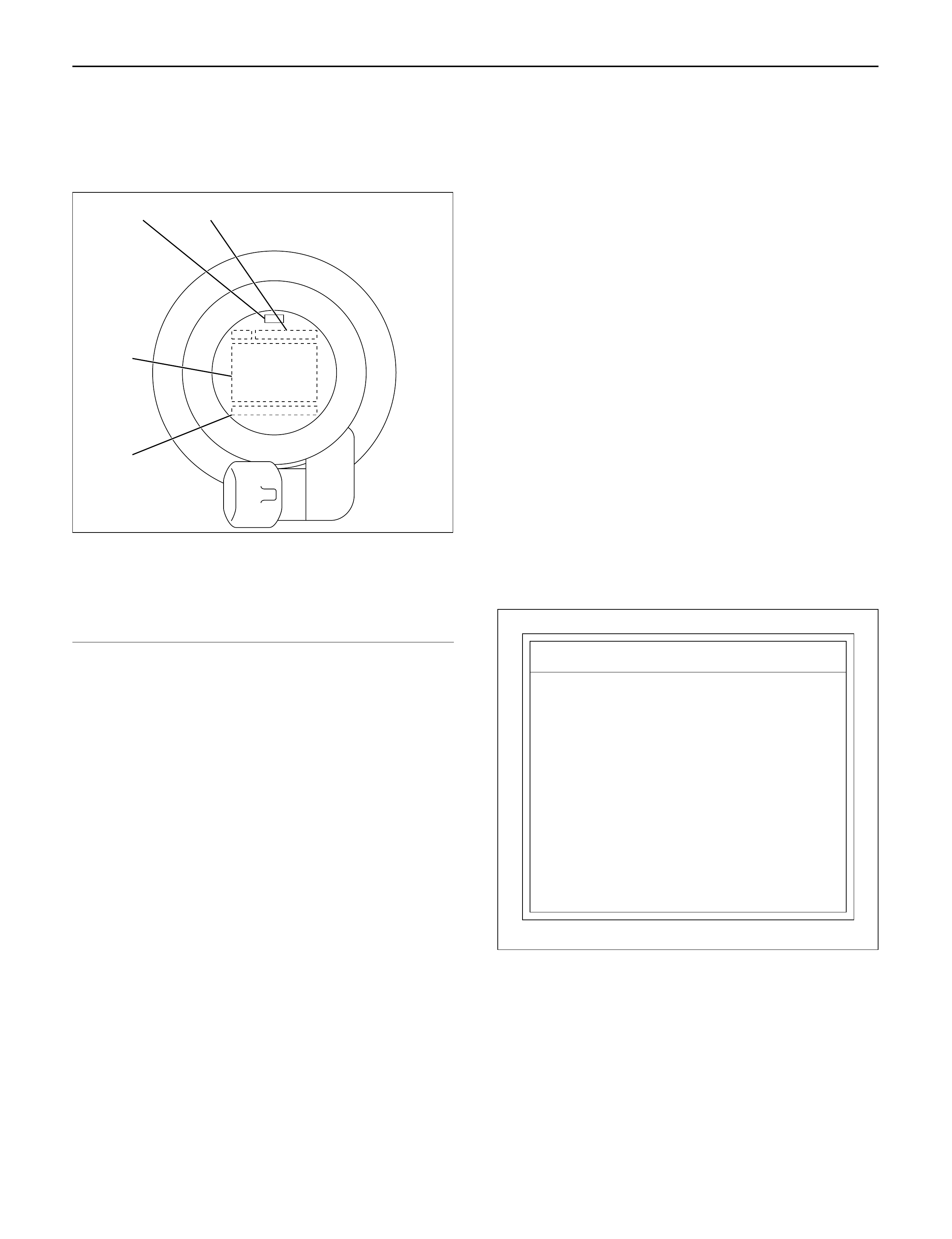
FUELFILLER CAP
The fuel filler cap contains a vacuum valve. If a
negative pressure develops in the fuel tank, the
external valve of the fuel filler cap opens to allow the
fresh air to flow into the fuel tank through the vacuum
valve.
INSPECTION
Check the seal ring in the filler cap for presence of any
abnormality and for seal condition.
Replace the filler cap, if abnormal.
Legend
(1) Vacuum Valve
(2) Pressure Valve
(3) Seal Ring
Legend
(1) Fuel Tank Assembly
(2) Fuel Gauge Unit
(3) Drain Plug
1
3
2
060R200247