
GENERAL DESCRIPTION
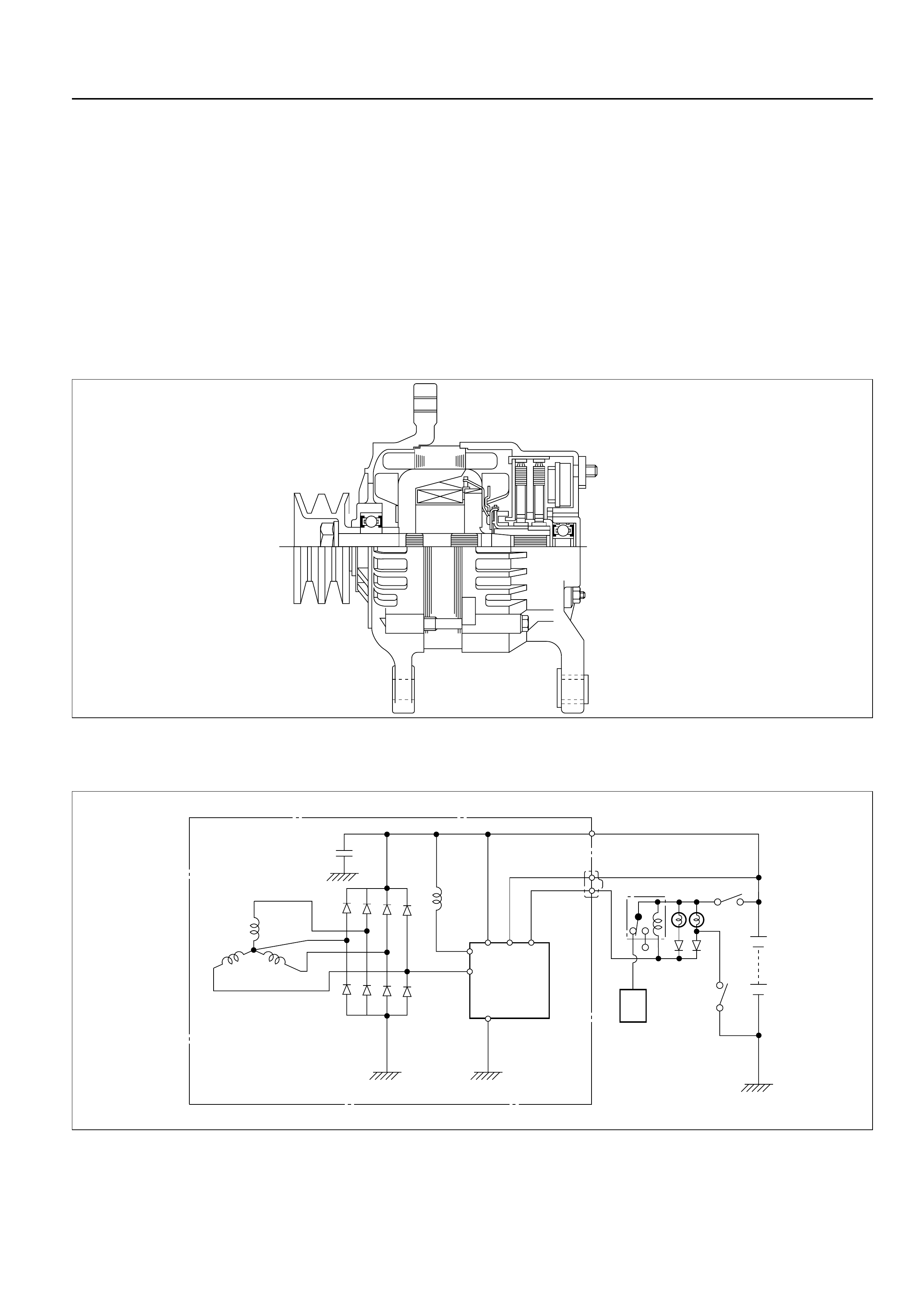
GENERATOR
CHARGING CIRCUIT
The charging system is the IC integral regulator
charging system and its main components are
connected as shown in Figure.
The regulator is a solid state type and it is mounted
along with the brush holder assembly inside the
generator installed on the rear end cover.
The generator does not require particular maintenance
such as voltage adjustment. The rectifier connected to
the stator coil has nine diodes to transform A.C. voltage
into D.C. voltage. This D.C. voltage is connected to the
output terminal of generator.
A06RW001
Condenser
Generator
Stator Coil
IC Regulator
Starter
SW
Rotor Coil
Battery
P
F
E
BS L
Relay
B
S
L
QOS
C/U
065RW00001
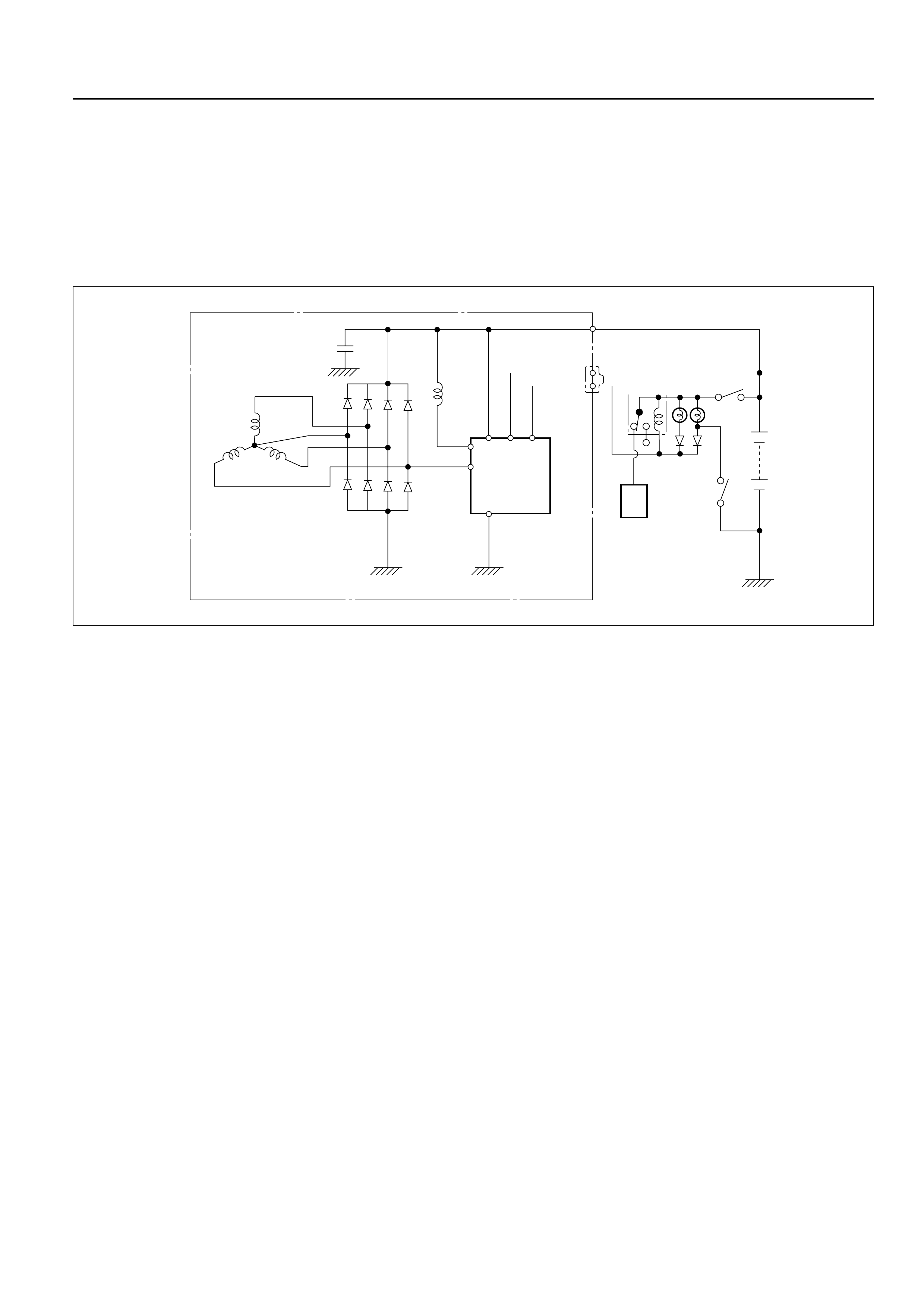
DIAGNOSIS
GENERAL ON-VEHICLE INSPECTION
The operating condition of the charging system is
indicated by the charge warning lamp. The warning
lamp comes on when the starter swtich is turned to
“ON” position. The charging system operates normally
if the lamp goes off when the engine starts. If the
warning lamp shows abnormality or if undercharged or
overcharged battery condition is suspected, perform
diagnosis by checking the charging system as follows:
Condenser
Generator
Stator Coil
IC Regulator
Starter
SW
Rotor Coil
Battery
P
F
E
BS L
Relay
B
S
L
QOS
C/U
065RW00001
1. Check visually the belt and wiring connector.
2. With the engine in stop status, turn the starter
switch to “ON” position and observe the warning
lamp.
1) If lamp does not come on:
Disconnect wiring connector from generator,
and ground terminal “L” on connector side.
2) If lamp comes on:
Repair or replace the generator.
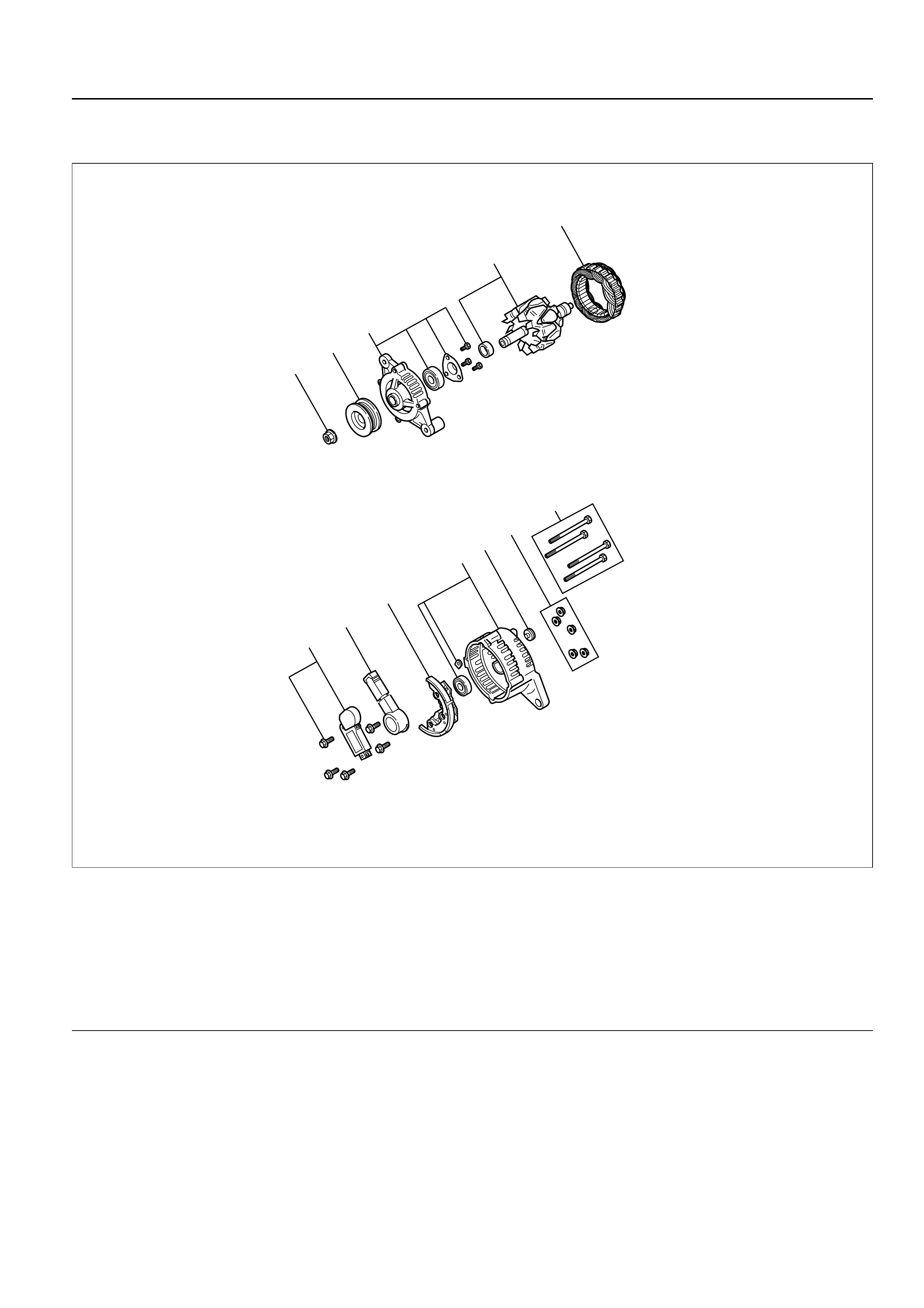
UNIT REPAIR
5
4
3
2
1
7
6
10
98
11
12
066RW022
Legend
(1) Pulley Nut
(2) Pulley
(3) Front Cover Assembly
(4) Rotor Assembly
(5) Stator Assembly
(6) Through Bolt
(7) Nut
(8) Terminal Insulator Plate
(9) Rear Cover Assembly
(10) Diode
(11) Brush Holder
(12) Regulator Assembly
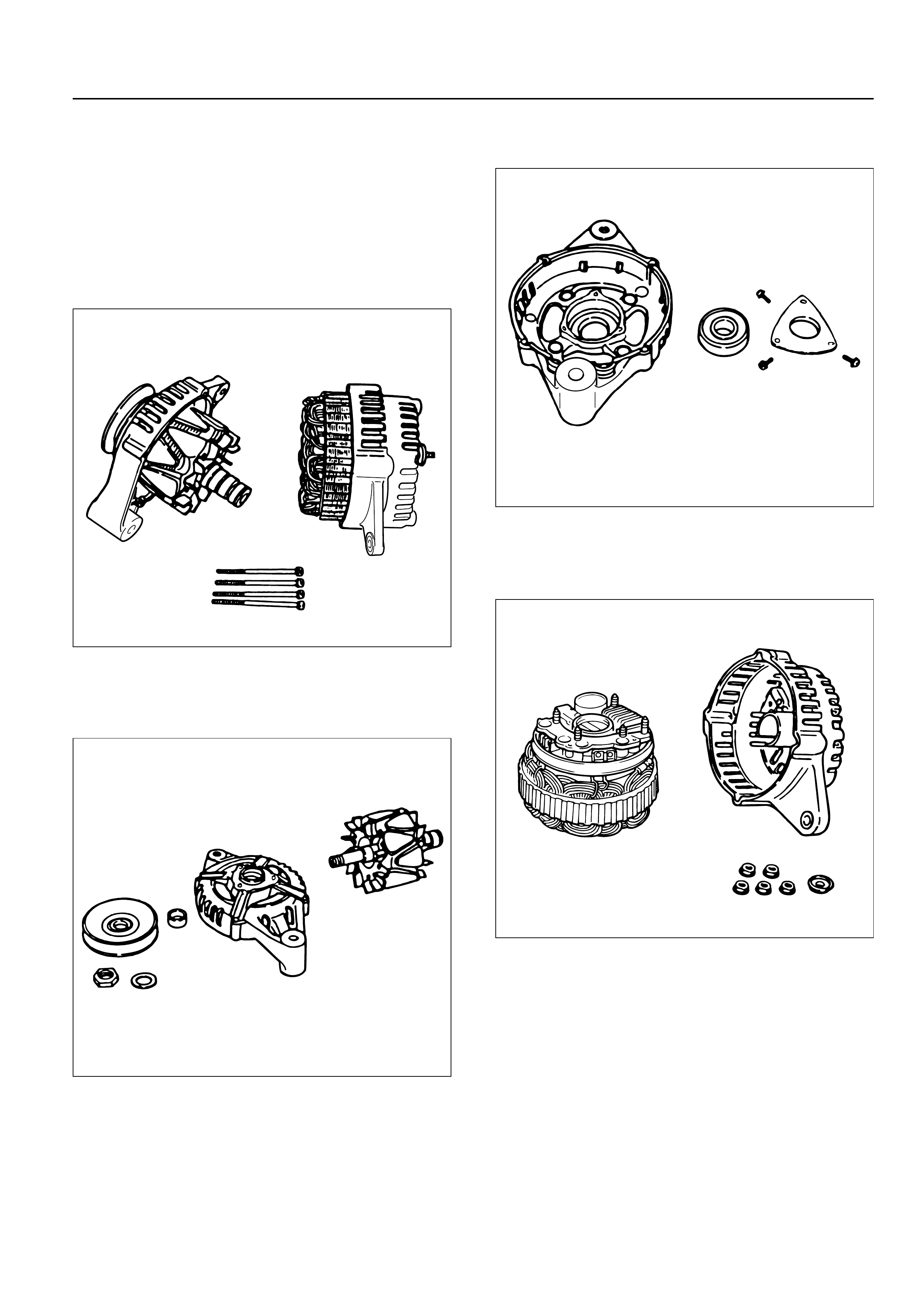
DISASSEMBLY
1. Remove the through bolt.
Insert the tip of a pry bar into the gaps between the
front cover and the stator core.
Pry apart and separate the front cover, rotor, the
rear cover and stator.
NOTE: Take care not to scratch or otherwise damage
the stator coil with pry bar.
2. Clamp the rotor in a vise and then remove the nut
and pulley.
3. Remove the rotor assembly from front cover.
4. Remove screws with bearing retainer from front
cover and remove bearing.
5. Remove the mounting nuts holding the “B”
terminal, the diode, and the brush holder.
6. Separate the rear cover from the stator.
F06RT021
F06RT022
F06RT023
F06RT024
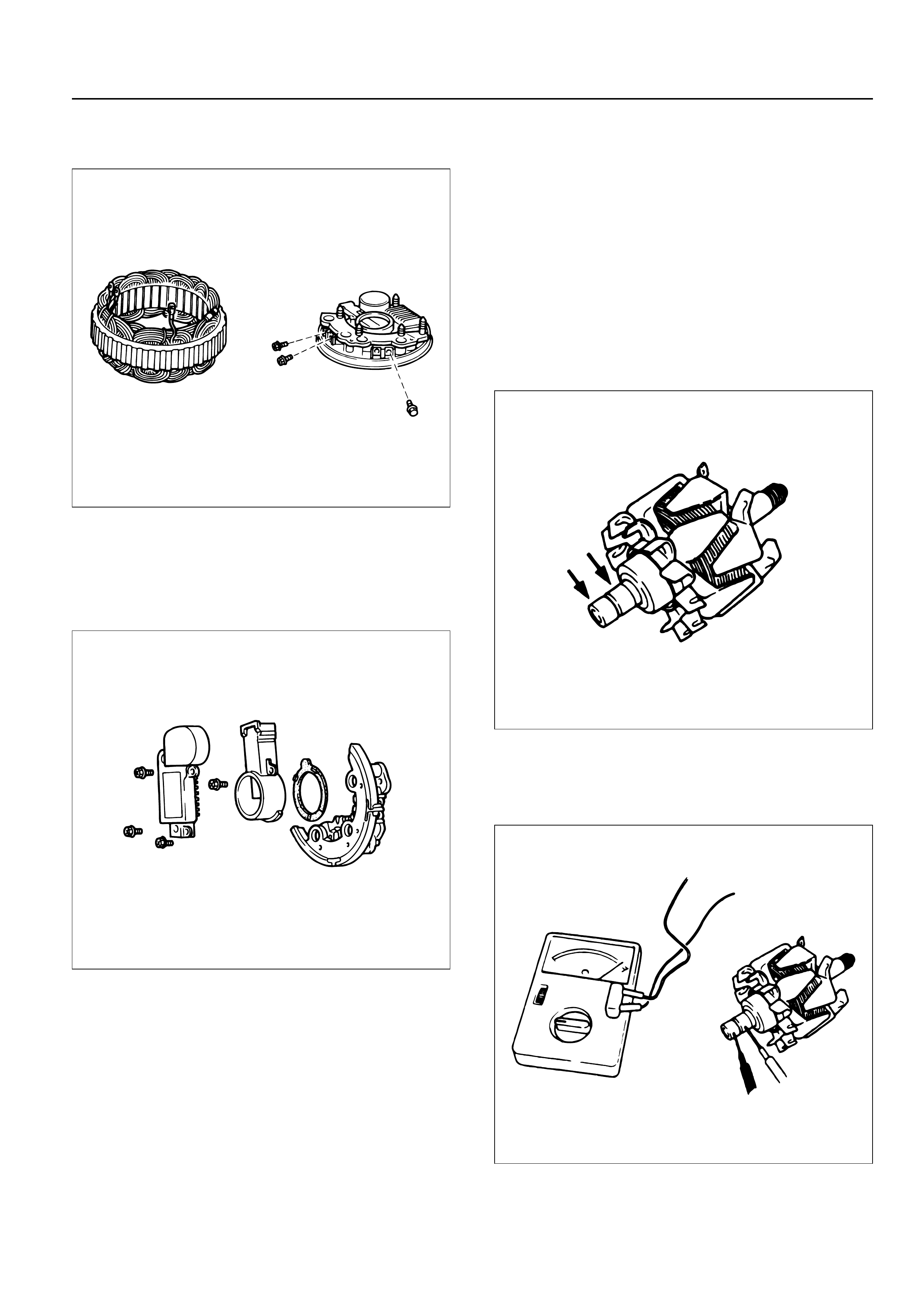
7. Remove bolts which secure stator terminal to
rectifier terminal, and remove stator.
8. Remove Bolts which secure regulator, rectifier and
brush-holder, and separate these parts.
NOTE: Do not apply a shock or load to regulator,
rectifier and brush holder.
INSPECTION AND REPAIR
Repair or replace necessary parts if extreme wear or
damage is found during inspection.
Rotor Assembly
1. Check the face of the slip rings for contamination
and roughness. If found to be scored, dress with a
fine sandpaper (#500 – 600). If found to be
contaminated, clean with a cloth saturated with
alcohol.
2. Measure the outside diameter of the slip rings.
Standard: 27 mm (1.06 in)
Limit: 26 mm (1.02 in)
3. Check resistance between slip rings, and replace if
there is no continuity.
Standard: 3.75 Ωor less
066RS030
066RW025
066RS032
066RS033
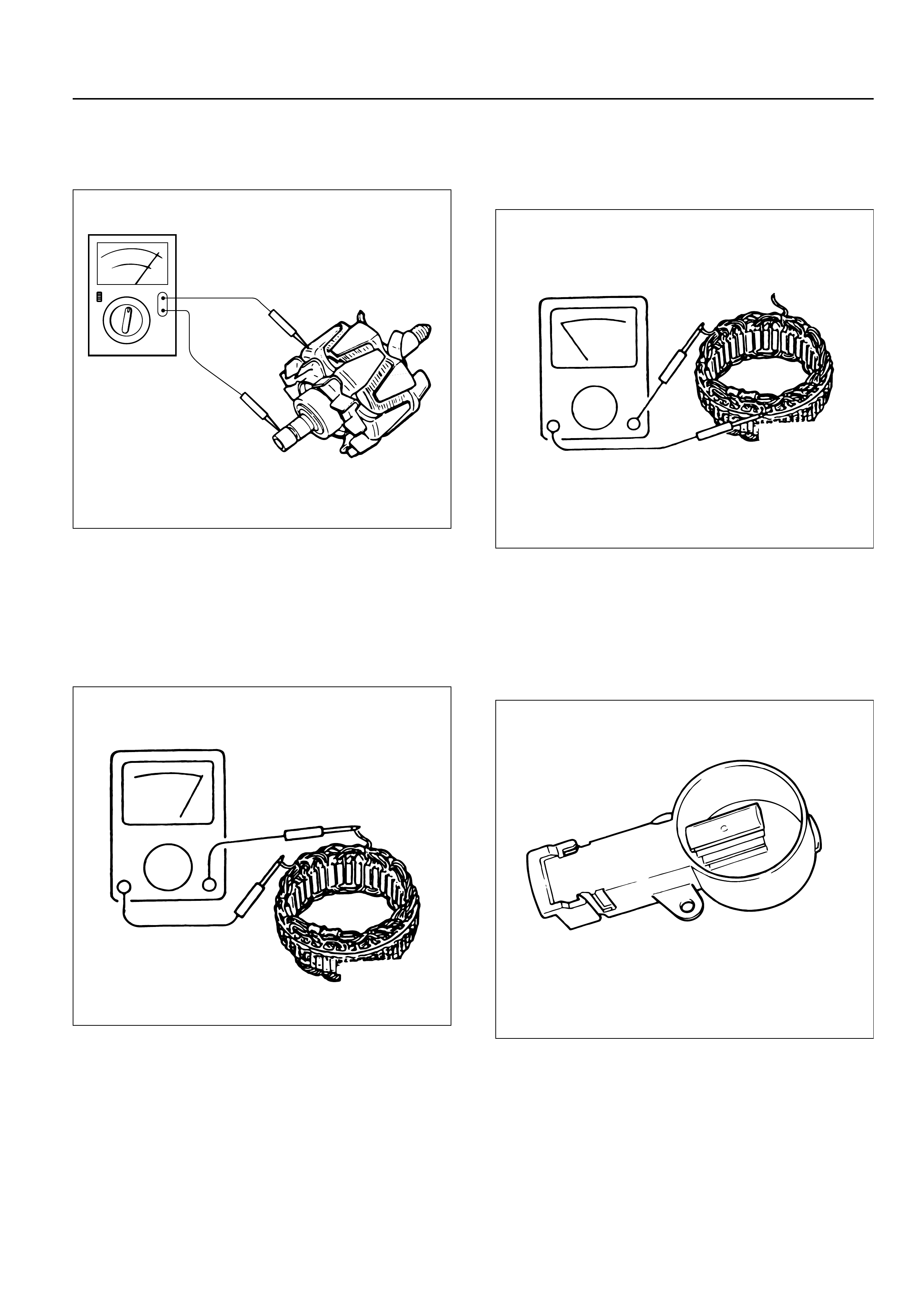
4. Check for continuity between slip ring and rotor
core.
In case of continuity, replace the rotor assembly.
Stator Coil
1. Check for continuity across the stator coils. If no
continuity exists, replace the coils.
Resistance value at 20°C
Standard: Approx 0.07Ω
2. Check for continuity across one of the stator coils
and stator core. If a continuity exists, replace the
coil.
Standard: More than 1MΩ
Brush
Measure the brush length.
If more than limit, replace the brush.
Standard: 18.0 mm (0.709 in)
Limit: 5.5 mm (0.217 in)
066RS017
066RS035
066RW024
066RS034

Rectifier Assembly
1. Measure the resistance between each diode
terminal and aluminum diode fin in forward and
reverse directions with the connection of the tester
leads switched. The diodes are normal if resistance
is nearly zero ohms in one direction and is infinitely
high in the other direction.
2. If a diode has no resistance or equal resistance in
both directions, it is defective and should be
replaced together with the holder.
IC Regulator Assembly
Connect a variable resistor, two 12V batteries, a fixed
resistor, and a voltmeter to the IC regulator as shown in
illustration.
a. Measuring equipment specifications
1. Fixed resistor (R1) : 10 Ohms / 3W
2. Variable resistor (Rv) : 0 – 300 Ohms / 12W
3. Batteries (BAT1, BAT2) : 12V (2 Batteries)
4. DC voltmeter : 0 – 50V / 0.5 steps (4 Check points)
b. Measuring procedure
1. Measure the voltage “V1” across the first battery
(BAT1). If the reading is between 10 and 13 volts,
the battery is normal.
2. Measure the voltage “V3” across both the batteries
(BAT1, BAT2). If the reading is between 20 and 26
bolts, the batteries are normal.
3. Gradually increase the resistance of the variable
resistor from zero. Measure the voltage “V2” (the
voltage across the F and E terminals).
Check to see that the voltage across “V1” changes
at this time. If there is no change, the voltage
regulator is faulty and must be replaced.
4. Measure the voltage at “V4” (the voltage across the
variable resistor center tap and terminal E with the
variable resistor resistance held constant). The
measure voltage should be within the specified
(14.4 ± 0.3 volts) limits. If it is not, the regulator
must be replaced.
Reassembly
To reassemble, follow the disassembly steps in the
reverse order, noting the following points:
NOTE:
1) Never make battery connections with polarities
reversed, or battery will be shorted via the diodes.
This will cause damage to the diodes.
2) Do not connect generator B terminal to ground; it is
connected directly to the battery.
This cable will burn if it is connected to ground.
3) Make sure to disconnect the positive (+) terminal of
the battery when quick-charging battery.
Diodes may be damaged due to abnormal pulse
voltage generated by the quick charger.
4) When reassembling the front section to rear
section, insert a stiff wire into hole in the rear face
of the rear cover from the outboard side to support
the brush in raised position, then insert the front
section to which rotor is assembled.
5) Reassemble parts carefully to be sure they fit into
their original position, paying attention to the
insulated portions.
6) Wipe insulating tubes, washers and plates clean
and install them in position carefully to avoid getting
oil or grease on them.
066RS036
R
E
BS
R1
RV
BAT2
BAT1
V2
V3
V4
V1
066RW029
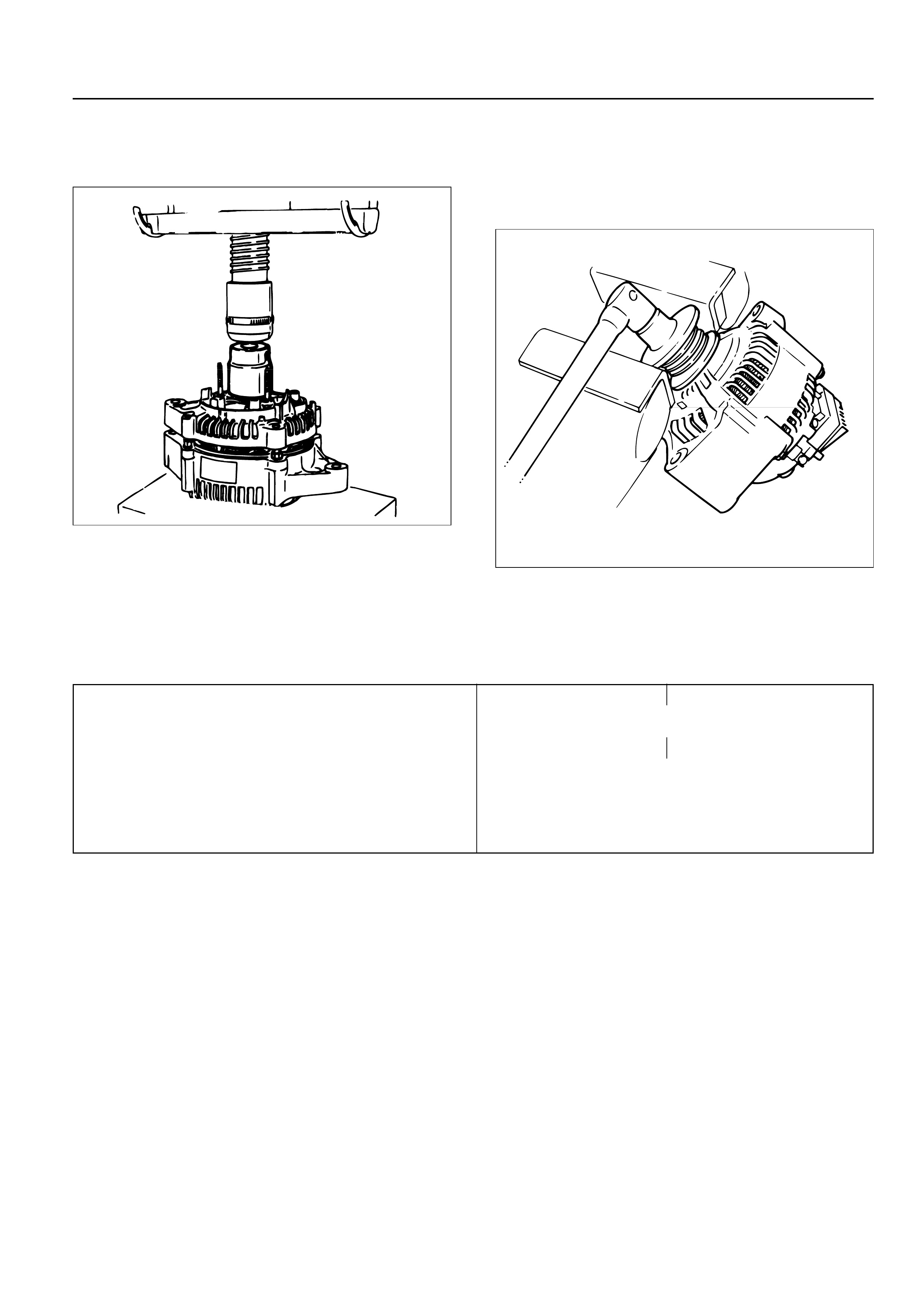
1. Using a press with a socket wrench attached,
reassemble rotor and rear end cover assembly in
the front cover.
2. Install pulley on the rotor.
Secure the pulley directly in the vise between two
copper plates, and tighten nut to the specified
torque.
Torque: 111 N·m (82 lb ft)
066RS022
066RS010
MAIN DATA AND SPECIFICATIONS
General Specifications
Model LR160-734B LR-170-760
Battery voltage V 12
Rated output A 60 70
Direction of rotation Clockwise
(as viewed from pulley side)
Rated rotation speed rpm 5,000
Maximum speed rpm 18,000