
STARTING SYTEM
GENERAL DESCRIPTION
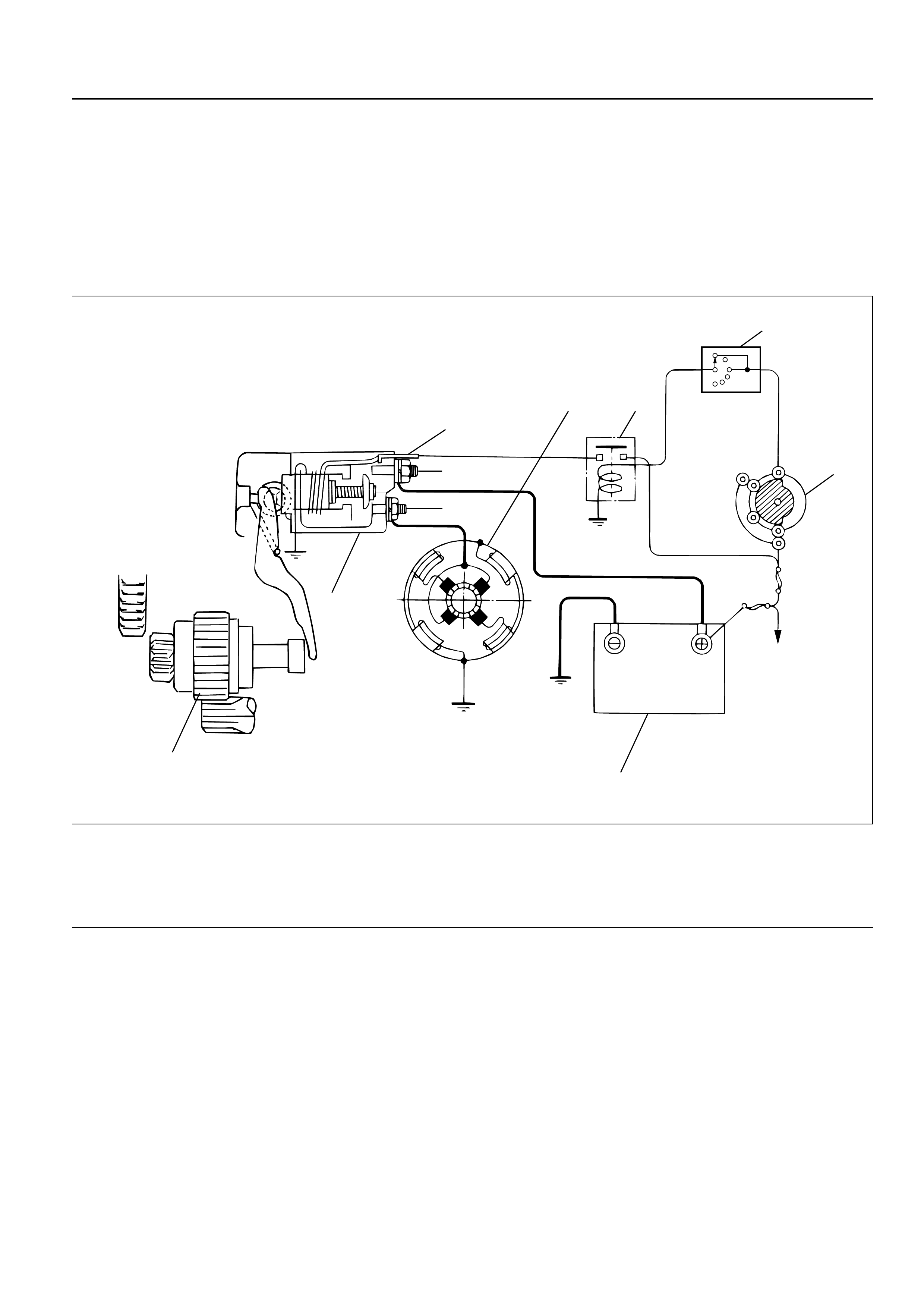
STARTING CIRCUIT
The cranking system consists of a battery, starter,
starter switch, starter relay, etc. and these main
components are connected as shown in the illustration.
“S”
“B”
“M”
Battery
5
4
3
2
IG1 ST
B2
B1
1
76
PNN
Legend
(1) Inhibitor Switch
(2) Starter Switch
(3) Battery
(4) Magnetic Switch
(5) Pinion Clutch
(6) Starter Motor
(7) Starter Relay
065RW039
STARTER
The starting system employs a magnetic type reduction
starter in which the motor shaft is also used as a pinion
shaft. When the starter switch is turned on, the contacts
of the magnetic switch are closed, and the armature
rotates. At the same time, the plunger is activated, and
the pinion is pushed forward by the shift lever to mesh
with ring gear.
Then, the ring gear runs to start the engine. When the
engine starts and the starter switch is turned off, the
plunger returns, the pinion is disengaged from the ring
gear, and the armature stops rotation. When the engine
speed is higher than the pinion, the pinion idles, so that
the armature is not driven.
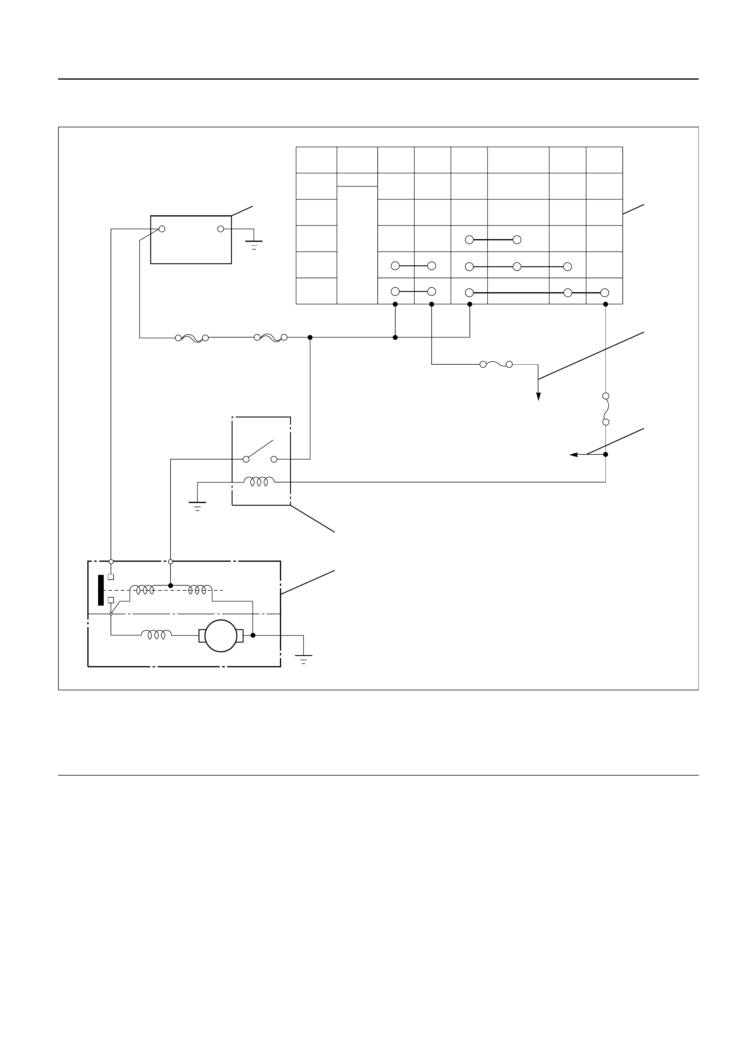
RELATION BETWEEN STARTER SWITCH AND STARTER
M
Key
Position B1 B2 ACCIG1 IG2 ST
LOCK
Key
Removed
Inserted
OFF
ACC
ON
START
BS
Battery
5
+-
2
1
6
3
4
Legend
(1) Starter Switch
(2) To Generator
(3) To QOS4 Control
(4) Starter Relay
(5) Magnetic Switch
(6) Battery
065RW036
ON-VEHICLE SERVICE
STARTER
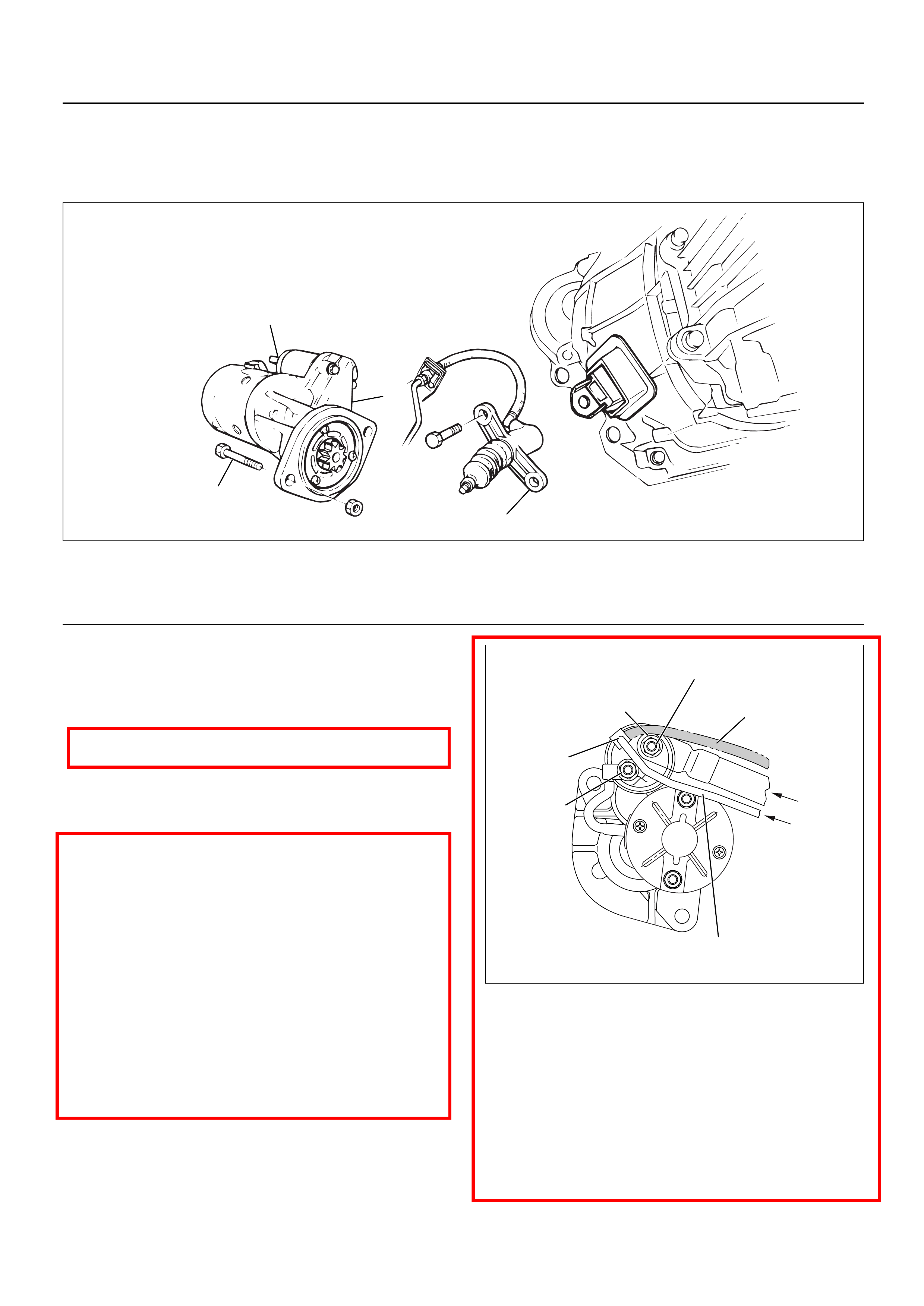
REMOVAL
1 Battery ground cable
2 Remove the slave cylinder and bind with wire it to
the frame.
3 Disconnect the connector from terminals “B” and
“S”.
4. Remove mounting bolts
5. Remove starter assembly
INSTALLATION
1. Install starter assembly, tighten the fixing bolt and
nut to the specified torque.
Torque: 94 N·m (9.6 kg·m/69 lb ft)
2.Reconnect the starter terminals.
CAUTION: When installing the starter motor wiring,
do not allow the S-circuit wiring to obstruct the B-
circuit terminal.
Install the wiring exactly as shown on the attached
illustration.
If S-circuit wiring obstructs the B-circuit terminal,
harness cover breakage and short circuiting may
occur.
2-1. Install the wire harness from the battery to the
terminal “B” with tightening torque 8.6 N·m
(0.88 kg·m/6.4 lb·ft).
2-2. Cover the terminal “B” together with wire
harness.
2-3. Connect the wire harness from starter relay to
the terminal “S”.
3. Install the clutch slave cylinder, tighten the fixing
bolt and nut to the specified torque.
Torque: 78 N·m (8.0 kg·m/58 lb·ft)
1
3
2
4
Legend
(1) Clutch Slave Cylinder
(2) Magnetic Switch
(3) Bolt
(4) Starter Assembly
065RW00003
Do not recommend
wiring route.
Recommend wiring route
from S terminal.
From
battery
From
starter relay
Terminal B
Terminal M
Terminal S
In this area,
Scratch to break the wire
cover and make shortage.
065RW00002
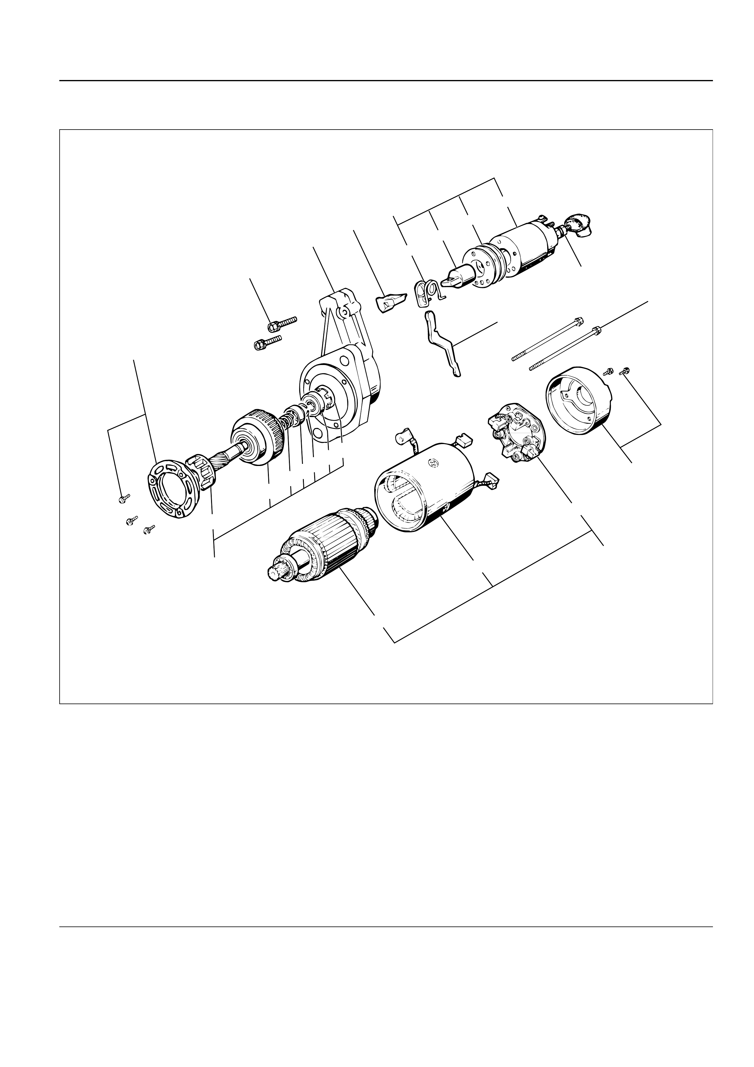
UNIT REPAIR
8
24
1
3
23
25
2
14
15
21
22 201918 17 16
10
9
11
13
12
7
6
5
4
Legend
(1) Terminal
(2) Bolt
(3) Magnetic Switch
(4) Torsion Spring
(5) Plunger
(6) Shim
(7) Magnetic Switch
(8) Through Bolt
(9) Rear Cover
(10) Motor Assembly
(11) Brush Holder
(12) Armature
(13) Yoke Assembly
(14) Bearing Retainer
(15) Pinion Assembly
(16) Bearing Holder
(17) Bearing
(18) Clip
(19) Stopper
(20) Spring
(21) Pinion Shaft
(22) Clutch
(23) Dust Cover
(24) Shift Lever
(25) Gear Case
065RW040
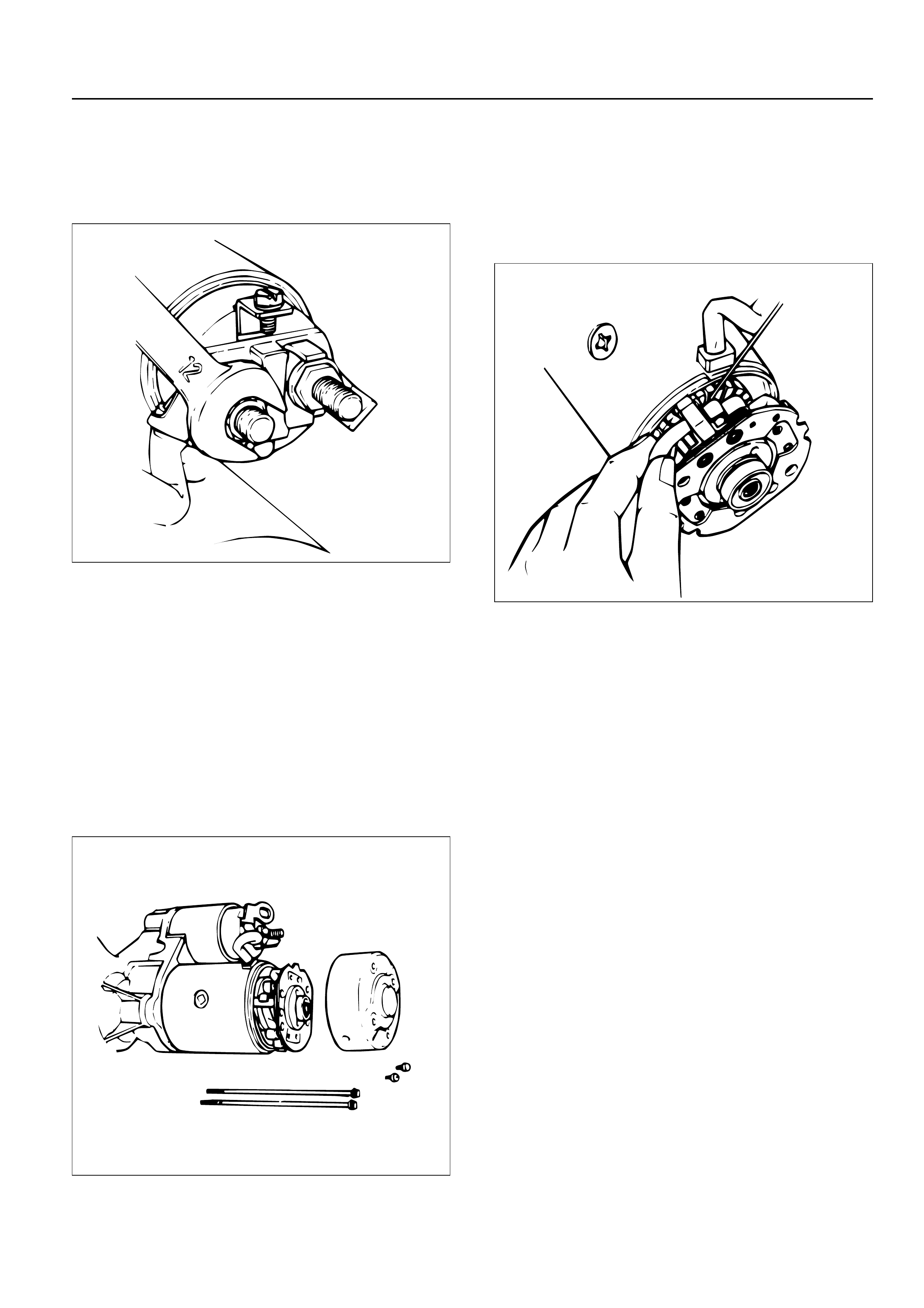
DISASSEMBLY
1. Terminal Nut
1) Loosen the nut on terminal “M” of magnetic
switch and disconnect the connector cable.
2. Bolt (2 pcs)
3. Magnetic Switch Assembly
4. Torsion Spring
1) Remove torsion spring from magnetic switch
assembly.
5. Plunger
6. Shim
7. Magnetic Switch
8. Through Bolt
9. Rear Cover
1) Remove the through bolts, then remove the rear
cover.
10. Motor Assembly
11. Brush Holder
1) Raise a brush spring to detach the negative side
of the brushes (2 pcs) from the commutator face
and remove the positive side of brushes (2 pcs)
from the positive side of brushes (2 pcs) from
the brush holder.
12. Armature
13. Yoke Assembly
14. Bearing Retainer
15. Pinion Assembly
16. Bearing Holder
17. Bearing
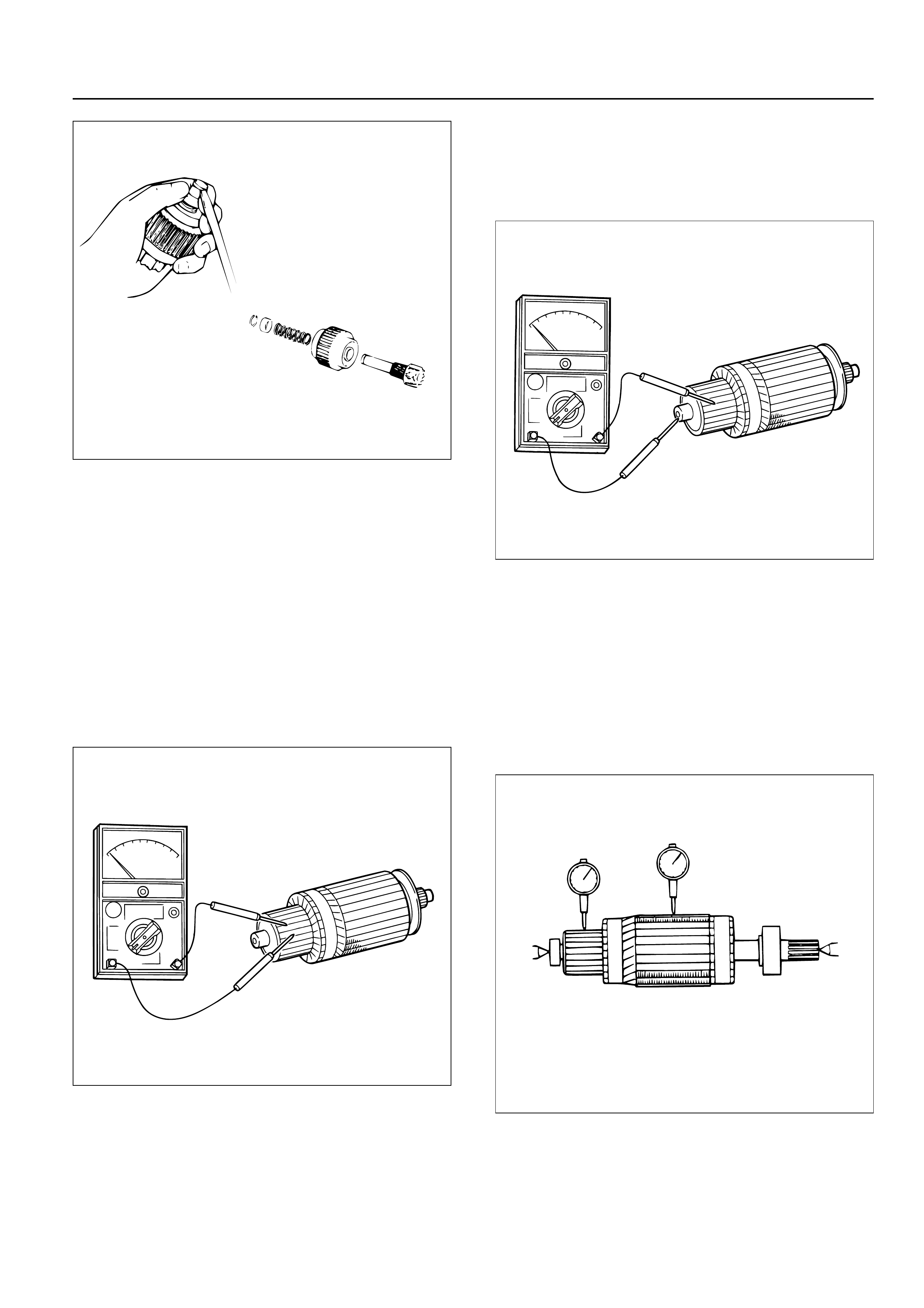
18. Pinion Stopper Clip
1) Remove the stopper clip using a screw driver of
equivalent size.
19. Pinion Stopper
20. Return Spring
21. Pinion Shaft
22. Clutch
23. Dust Cover
24. Shift Lever
25. Gear Case
065RW044
065RW043
065RW042
INSPECTION AND REPAIR
Repair or replace necessary parts if extreme wear or
damage is found during inspection.
Armature
1) Measure the outer diameter of commutator, and
replace with a new one if it is out of the limit.
Standard: 38.0 mm (1.50 in)
Limit: 36.5 mm (1.44 in)
2) Check for continuity between commutator and
segments. Replace commutator if there is no
continuity (i.e., disconnected).
3) Check for continuity between commutator and
shaft. Also, check for continuity between
commutator and armature core, armature core and
shaft. Replace commutator if there is continuity
(i.e., internally grounded).
4) Measure runout of armature core and commutator
with a dial gage. Repair or replace, if it exceeds the
limit.
Armature
Standard: 0.05 mm (0.002 in) Max.
Limit: 0.1 mm (0.004 in)
Commutator
Standard: 0.05 mm (0.002 in) Max.
Limit: 0.1 mm (0.004 in)
065RW041
065RS015
065RS016
045RW045
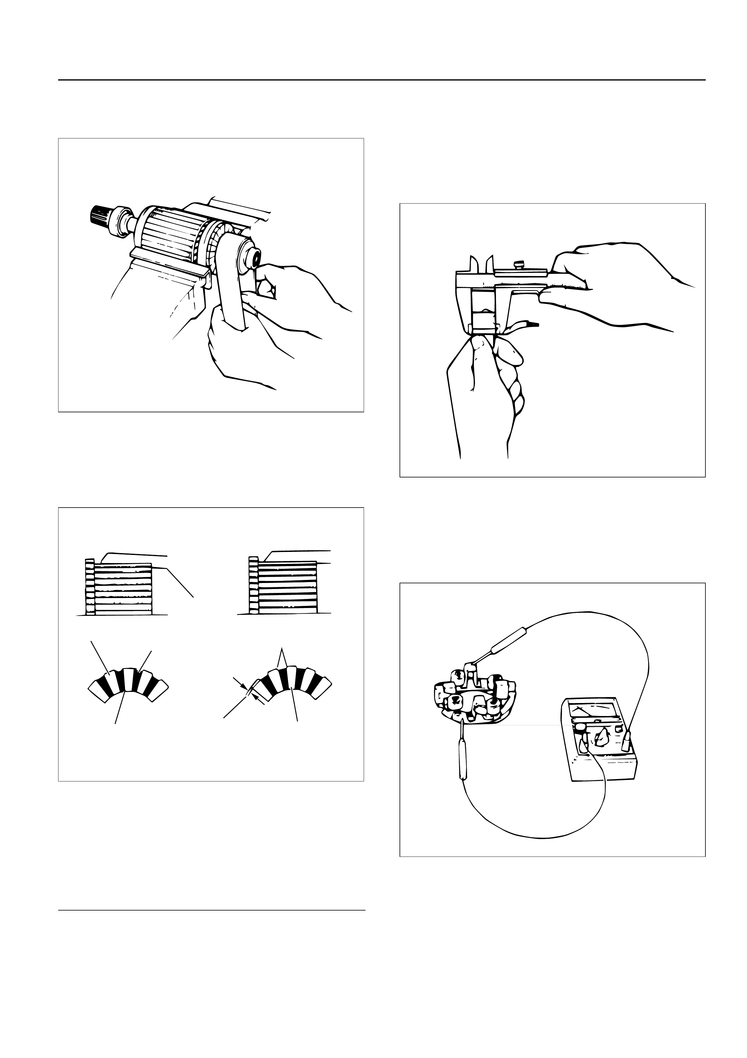
5) Polish the commutator surface with sand paper
#500 to #600 if it is rough.
6) Measure the depth of insulator in commutator.
Repair, if it is below the limit.
Standard: 0.5 – 0.8 mm (0.02 – 0.03 in)
Limit: 0.2 mm (0.008 in)
Legend
(1) Steel Saw
(2) Chamfer
(3) Correct Condition
(4) Depth of Insulator
(5) Incorrect Condition
(6) Insulator
(7) Commutator Segment
Brush
1) Measure the length of brush.
Replace with a new one, if it is below the limit.
Standard: 18.0 mm (0.71 in)
Limit: 11.0 mm (0.43 in)
Brush holder
1) Check for continuity between brush holder (+) and
base (–). Replace, if there is continuity (i.e.,
insulation is broken).
065RW105
1
6
53
4
2
7
065RW102
065RW103
065RW104
2) Inspect the brush springs for wear, damage or other
abnormal conditions.
Standard: 28 – 35 N (2.9 – 3.6 kg/6.4 – 7.9 lb)
Magnetic switch
1) Continuity of shunt coil
Check for continuity between terminals S and coil
case.
Replace, if there is not continuity (i.e., coil is
disconnected.)
2) Continuity of series coil
Check for continuity between terminals S and M.
Replace, if there is no continuity (i.e., coil is
disconnected).
3) Continuity of contacts
With the plunger faced downward, push down the
magnetic switch. In this state, check for continuity
between terminals B and M. Replace, if there is no
continuity (i.e., contacts are faulty).
065RW052
065RW017
065RW018
065RW016
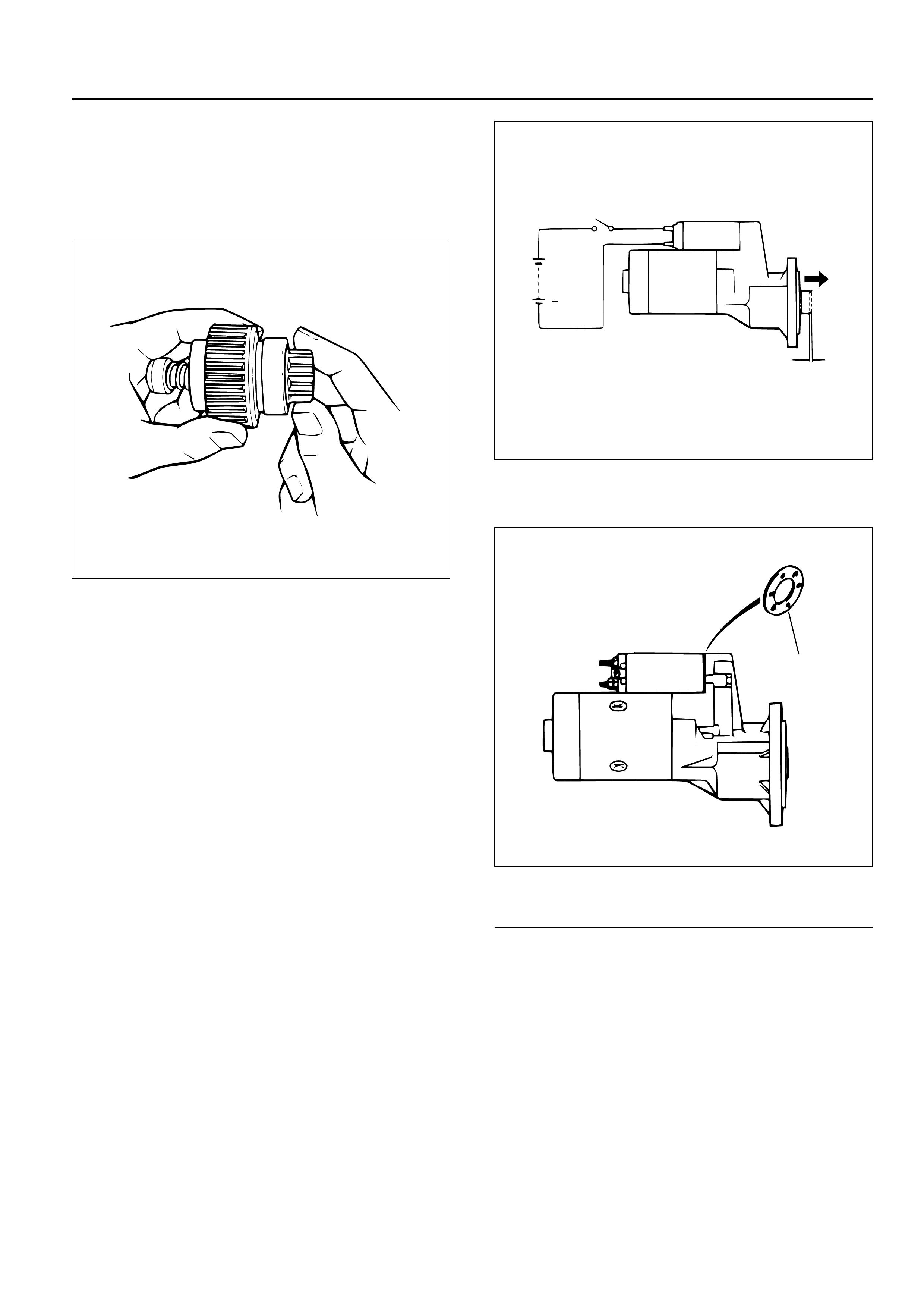
Pinion
1) Check by hand to see if the pinion rotates smoothly
in the dirve direction, or if it is locked when it is
rotated reversely.
If not, replace the pinion.
Yoke assembly
1) Check the magnet inside the yoke.
Replace the yoke assembly if it is broken.
REASSEMBLY
To install, follow the removal steps in the reverse order,
noting the following points:
Grease application places
1) Gears in reduction gear
2) Shift lever operating portion
3) Sliding potion of pinion
4) Plunger sliding portion of magnetic switch
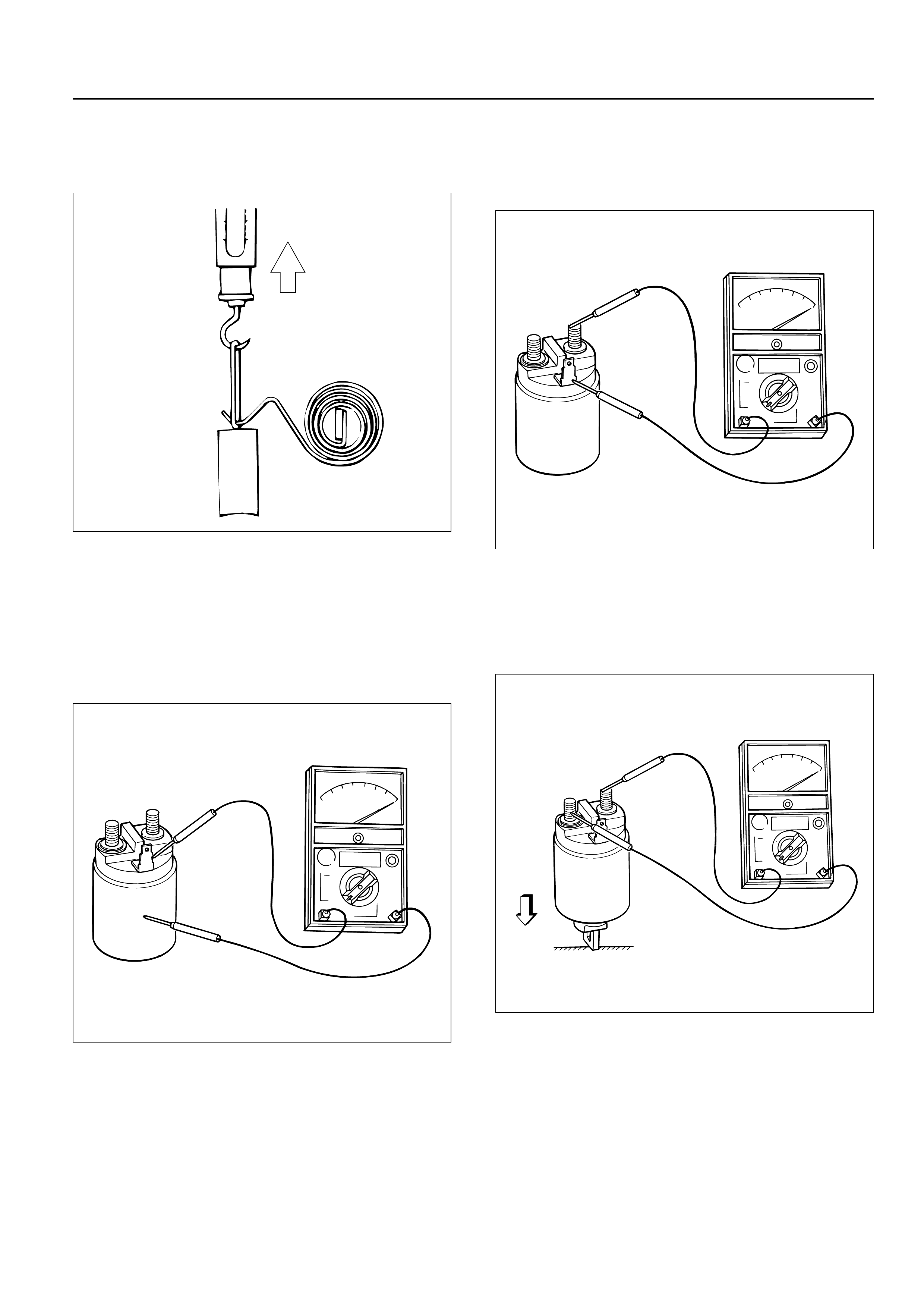
Pinion jump-out dimension
1) Connect the (+) cable of battery to terminal S and
the (–) cable to terminal M. Turn the switch on, and
measure pinion travel dimension “L” in thrust
direction from the jump-out position.
In measuring the dimension, pull the pinion out a little in
the arrow direction.
Dimension L: 0.3 – 1.5 mm (0.01 – 0.06 in)
If the measured value is out of standard, adjust the of
shims.
Legend
(1) Shim
065RW048
S
+
L
M
065RW054
1
065RW053
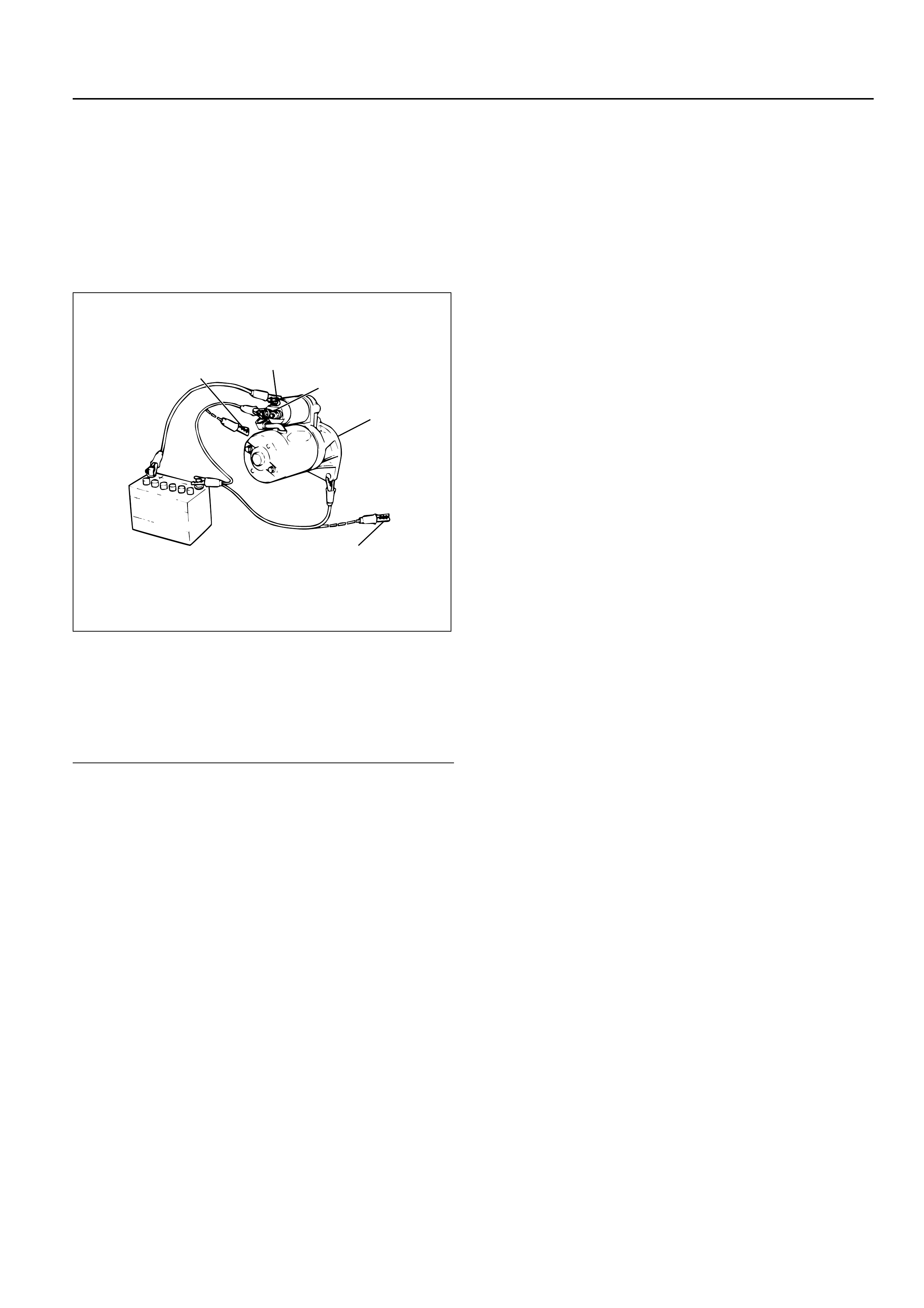
MAGNETIC SWITCH
Pull-out test
Connect the magnetic switch to the battery as shown.
The negative side to the “M” terminal and the magnetic
switch body (housing); the positive side to the “S”
terminal. If the pinion has been ejected, the pull-in coil
is satisfactory.
Legend
(1) Terminal “S”
(2) Terminal “M”
(3) Starter
(4) For Return Test
(5) For Hold-In Test
Hold-in test
1. Next disconnect the “M” terminal.
2. The pinion should remain in the ejected position.
Return test
When the switch body is disconnected, the pinion
should return quickly.
2
1
5
3
4
065RW055