
SECTION 6E - 4JX1-TC 3.0L ENGINE
DRIVEABILITY AND EMISSIONS
Specification
Diagrams and Schematics
ECM Wiring Diagram
ECM Pinouts
ECM Pinout Table, 32-Way Connector -
J1 RED - Upper
ECM Pinout Table, 32-Way Connector -
J1 RED - Lower
ECM Pinout Table, 32-Way Connector -
J2 BLUE - Upper
ECM Pinout Table, 32-Way Connector -
J2 BLUE - Lower
ECM Pinout Table, 5-Way Connector - J3
Component Locator
Abbreviations Charts
Diagnosis
Strategy-Based Diagnostics
DTC Stored
No DTC
No Matching Symptom
Intermittents
No Trouble Found
Verifying Vehicle Repair
General Service Information
Serviceability Issues
Visual/Physical Engine Compartment Inspection
Basic Knowledge of Tools Requir ed
Serial Data Communications
Class II Serial Data Communications
On-Board Diagnostic (OBD)
On-Board Diagnostic Tes ts
Comprehensive Component Monitor Diagnostic
Operation
Common OBD Terms
The Diagnostic Executiv e
DTC Types
Verifying Vehicle Repair
Reading Flash Diagnostic Trouble Co des
Reading Diagnostic Trouble Codes
Using a TECH 2
Tech 2 Scan Tool
Getting Started
DTC Modes
DTC Information Mode
Injector Test
EGR Valve Test
Rail Pressure Control Valve Test
Injector Balance Test
Data Programming in Case of ECM Change
Rail Pressure Sensor Programming
Injector Group Sign Programming
(Injector Change)
On-Board Diagnostic (OBD) System Check
Engine Control Module ECM Diagnosis
Multiple ECM Information Sensor DTCS Set
EGR (Exhaust Gas Recirculation) Diagnosis
Tech 2 Data Definitions and Rang es
Typical Scan Data Values
No Malfunction Indicator Lamp (MIL)
Malfunction Indicator Lamp (MIL) “ON” Steady
Engine Cranks But Will Not Run
Exhaust Gas Recirculation (EGR) System Check
ECM Diagnostic Trouble Codes
Diagnostic Trouble Code (DTC) P0 107 (Flash
DTC 34 ) MAP Sensor Circuit Low Voltage
Diagnostic Trouble Code (DTC) P0 108 (Flash
DTC 34) MAP Sensor Circuit High Voltage
Diagnostic Trouble Code (DTC) P0 112 (Flash
DTC 23) IAT Sensor Circuit Lo w Voltage
Diagnostic Trouble Code (DTC) P0 113 (Flash
DTC 23) IAT Sensor Circuit High Voltage
Diagnostic Trouble Code (DTC) P0 117 (Flash
DTC 14) ECT Sensor Low Voltage
Diagnostic Trouble Code (DTC) P0 118 (Flash
DTC 14) ECT Sensor High Voltage
Diagnostic Trouble Code (DTC) P0 121 (Flash
DTC 33) AP Sensor Rationality
Diagnostic Trouble Code (DTC) P0 122 (Flash
DTC 21) AP Sensor Low Voltage
Diagnostic Trouble Code (DTC) P0 123 (Flash
DTC 21) AP Sensor High Voltage
Techline
Techline
Techline
Techline
Techline
Techline
Techline
Techline

Diagnostic Trouble Code (DTC) P0 182 (Flash
DTC 15) FT Sensor Low Voltage
Diagnostic Trouble Code (DTC) P0 183 (Flash
DTC 15) FT Sensor High Voltage
Diagnostic Trouble Code (DTC) P0 192 (Flash
DTC 63) Rail Pressure Sensor Low Voltage
Diagnostic Trouble Code (DTC) P0 193 (Flash
DTC 63) Rail Pressure Sensor High Voltage
Diagnostic Trouble Code (DTC) P1 193 (Flash
DTC 64) RPCV Circuit Open/Short
Diagnostic Trouble Code (DTC) P1 194 (Flash
DTC 61) Rail Pressure System Low Voltage
Diagnostic Trouble Code (DTC) P1 195 (Flash
DTC 61) Rail Pressure System High Voltage
Diagnostic Trouble Code (DTC) P1 196 (Flash
DTC 62) Rail Pressure System High Warning
Diagnostic Trouble Code (DTC) P0 197 (Flash
DTC 16) Oil Temp Sensor Low Voltage
Diagnostic Trouble Code (DTC) P0 198 (Flash
DTC 16) Oil Temp Sensor High Voltage
Diagnostic Trouble Code (DTC) P0 201 (Flash
DTC 51) Injector # 1 Circuit Fault
Diagnostic Trouble Code (DTC) P0 202 (Flash
DTC 52) Injector # 2 Circuit Fault
Diagnostic Trouble Code (DTC) P0 203 (Flash
DTC 52) Injector # 3 Circuit Fault
Diagnostic Trouble Code (DTC) P0 204 (Flash
DTC 54) Injector # 4 Circuit Fault
Diagnostic Trouble Code (DTC) P0 217 (Flash
DTC 22) High Coolant Temp Waring
Diagnostic Trouble Code (DTC) P1 217 (Flash
DTC 36) High Oil Temp Warning
Diagnostic Trouble Code (DTC) P0 219 (Flash
DTC 11) Engine Ov er Speed Warning
Diagnostic Trouble Code (DTC) P0 336
(Flash DTC 43) CKP (Crank Position) Sensor
Out of Synchro
Diagnostic Trouble Code (DTC) P0 337
(Flash DTC 43) CKP (Crank Position)
Sensor No Signal
CKP (Crank Position) Sensor No Signal
(MY1999 - MY2002 VEHICLES ONLY)
Diagnostic Trouble Code (DTC) P0 341
(Flash DTC 41) CMP (Cam Position)
Sensor Out of Sy nchro
Diagnostic Trouble Code (DTC) P0 342 (Flash
DTC 41) CMP (Cam Posi tion) Sensor No Signal
CMP (Cam Position) Sensor No Signal
(MY1999 - MY2002 VEHICLES ONLY)
Diagnostic Trouble Code (DTC) P0 380 (Flash
DTC 66) Glow Relay Circuit Open/Short
Diagnostic Trouble Code (DTC) P0 381 (Flash
DTC 67) Glow Lamp Circuit Open/Sh ort
Diagnostic Trouble Code (DTC) P1 403
(Flash DTC 32) EGR EVRV Fault
Diagnostic Trouble Code (DTC) P1 404
(Flash DTC 31) EGR VSV Circuit
Diagnostic Trouble Code (DTC) P0 405
(Flash DTC 26) EGR Pressure Sensor
Diagnostic Trouble Code (DTC) P1 405 (Flash
DTC 37) EGR EVRV Circuit Open/Short
Diagnostic Trouble Code (DTC) P0 406 (Flash
DTC 26) EGR Pressure Sensor High Voltage
Diagnostic Trouble Code (DTC) P0 475
(Flash DTC 71) EXH #1 VSV Circuit
Diagnostic Trouble Code (DTC) P1 475 (Flash
DTC 71) EXH #2 VSV Circuit Open/Short
Diagnostic Trouble Code (DTC) P1 485 (Flash
DTC 74) ITP (Intake Thorottle Positio n)
Sensor Low Voltage
Diagnostic Trouble Code (DTC) P1 486 (Flash
DTC 74) ITP (Intake Throttle Position)
Sensor High Voltage
Diagnostic Trouble Code (DTC) P1 487
(Flash DTC 73) Intake Thr ottle System
Circuit Open/Start
Diagnostic Trouble Code (DTC) P1 488
(Flash DTC 72) Intake Thr ottle Motor
Control Circuit Signal Gap
Diagnostic Trouble Code (DTC) P0 502 (Flash
DTC 24) VSS (Vehicle Speed Sensor) No Signal
Diagnostic Trouble Code (DTC) P0 510 (Flash
DTC 75) Idle SW Malfunction, Open Circuit
Diagnostic Trouble Code (DTC) P1 510 (Flash
DTC 75) Idle SW Malfunction Short Circuit
Diagnostic Trouble Code (DTC) P0 562
(Flash DTC 35) System Voltage Too Low
Diagnostic Trouble Code (DTC) P1 562 (Flash
DTC 35) System Voltage Too Low at Cranking
Diagnostic Trouble Code (DTC) P1 587
(Flash DTC 25) Brake SW Malfunction
Diagnostic Trouble Code (DTC) P1 588
(Flash DTC 25) Brake SW Malfunction
Diagnostic Trouble Code (DTC) P0 601
(Flash DTC 55) ECM Checksum Error
Diagnostic Trouble Code (DTC) P1626 -
No Response From Immobiliser
Diagnostic Trouble Code (DTC) P1631 -
Received Response Was Not Correct
Diagnostic Trouble Code (DTC) P1648 -
Received Incorrect Security Code
Diagnostic Trouble code (DTC) P1 649 - Security
Code & Security Key Not Programmed
Diagnostic Trouble Code (DTC) P0 650 (Flash
DTC 77) Check Engine Lam Circuit Open/Short
Diagnostic Trouble Code (DTC) P0 654 (Flash
DTC 27) Tachometer Circuit Open/Short
Diagnostic Trouble Code (DTC) P1 655 (Flash
DTC 17) Thermo Relay Circuit Open/Short
Diagnostic Trouble Code (DTC) P1 657 (Flash
DTC 76) ECM Main Relay Circuit Open/Short
Diagnostic Trouble Code (DTC) P1 589 (Flash
DTC 47) Transmission SW Circui t Open/Short

Symptom Diagnosis
Default Matrix Table
On-Vehicle Service
Camshaft Position (CMP) Sensor
Crankshaft Position (CK P) Sensor
Engine Coolant Temperature (ECT) Sensor
Intake Air Temperature (IAT) Sensor
Manifold Absolute Pressure (M AP) Sensor
Oil Temperature (OT) Sensor
Malfunction Indicator Lamp (MIL)
Engine Control Module (ECM)
EEPROM
Intake Throttle Position (ITP) Sensor
Vehicle Speed Sensor (VSS)
Air Cleaner/Air Filter
Accel Position (AP) Sensor
Accelerator Pedal Replacement
Fuel Filter Cap
Fuel Filter
Fuel Gauge Unit
Fuel Injectors
Fuel Temperature Sensor
Rail Pressure (RP) Sensor
Fuel Tank
Throttle Body (TB)
Air Conditioning (A/C) Relay
Exhaust Gas Recirculation (EGR)
Vacuum Switch Valve (VSV)
Electronic Vacuum Regurating Valve (EVRV)
Wiring and Connectors
Wire Harness Repair: Twisted Shielded Cable
Twisted Leads
Weather-Pack Connector
Com-Pack III
Metri-Pack
General Description (ECM and Sensors)
57X Reference ECM Input
A/C Request Signal
Crankshaft Position (CK P) Sensor
Camshaft Position (CMP) Sensor and Signal
Engine Coolant Temperature (ECT) Sensor
Electrically Erasable Programmable
Read Only Memory (EEPROM)
Intake Air Temperature (IAT) Sensor
Manifold Absolute Pressure (M AP) Sensor
Engine Control Module (ECM)
ECM Function
ECM Components
ECM Voltage Description
ECM Input/Outputs
ECM Service Precautions
Intake Throttle Position (ITP) Sensor
Transmission Range S witch
Accelerator Position Sensor (AP)
Aftermarket Electrical and Vacuum Equipment
Electrostatic Discharge Damage
General Description (Air Induction)
Air Induction System
General Description (Fuel Metering)
Deceleration Mode
Fuel Injector
Fuel Metering System Components
A/C Clutch Diagnosis
A/C Request Signal
General Description Exhaust Gas
Recirculation (EGR) System
EGR Purpose
Fuse and Relay Panel (Underhood
Electrical Center)

Specification
Tightening Specifications
Application N·m Kg·m Lb Ft. Lb In.
Camshaft Position Sensor Retaining Screw 9 0.9 — 78
Crankshaft Position Sensor Mounting Bolt 9 0.9 — 78
Engine Coolant Temperature Sensor 19 1.9 14 —
Throttle Body Mounting Nuts 20 2.0 14 —
VSS Retaining Bolt 16 1.6 12 —
MAP Sensor Screw 4 0.4 — 35
EGR VSV Bolts 8 0.8 — 69
Fuel Temp Sensor 19 1.9 14 —
Oil Temp Sensor Bolt 19 1.9 14 —
Rail Pressure Sensor Bolt 20 2.0 14 —
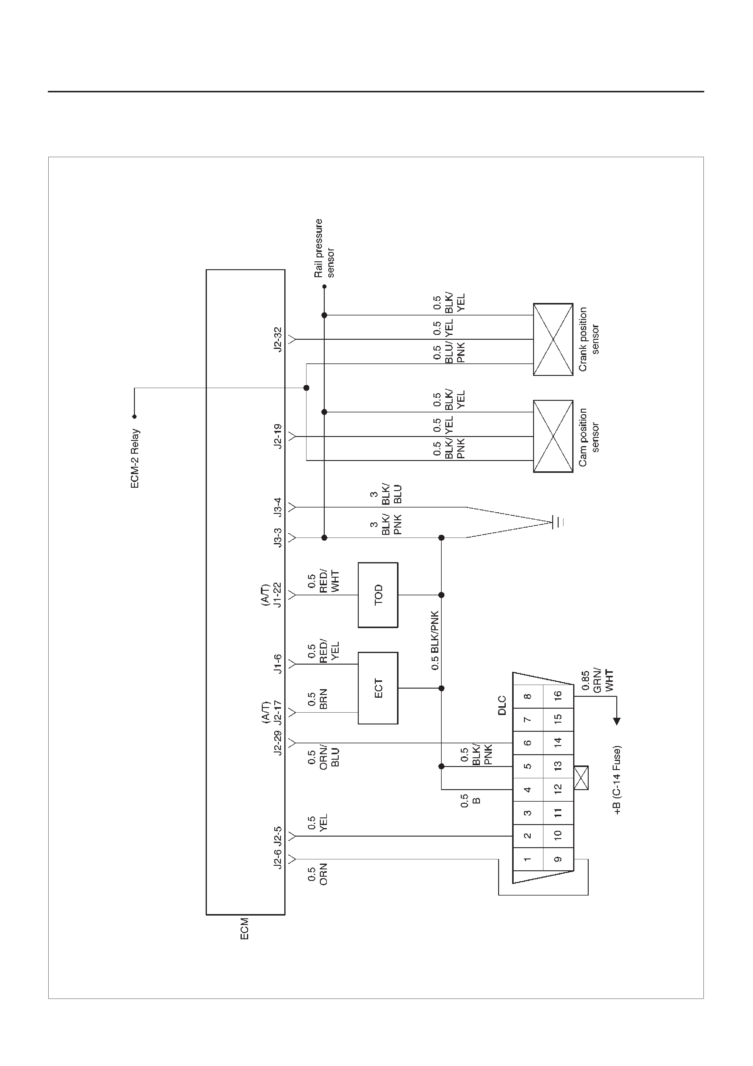
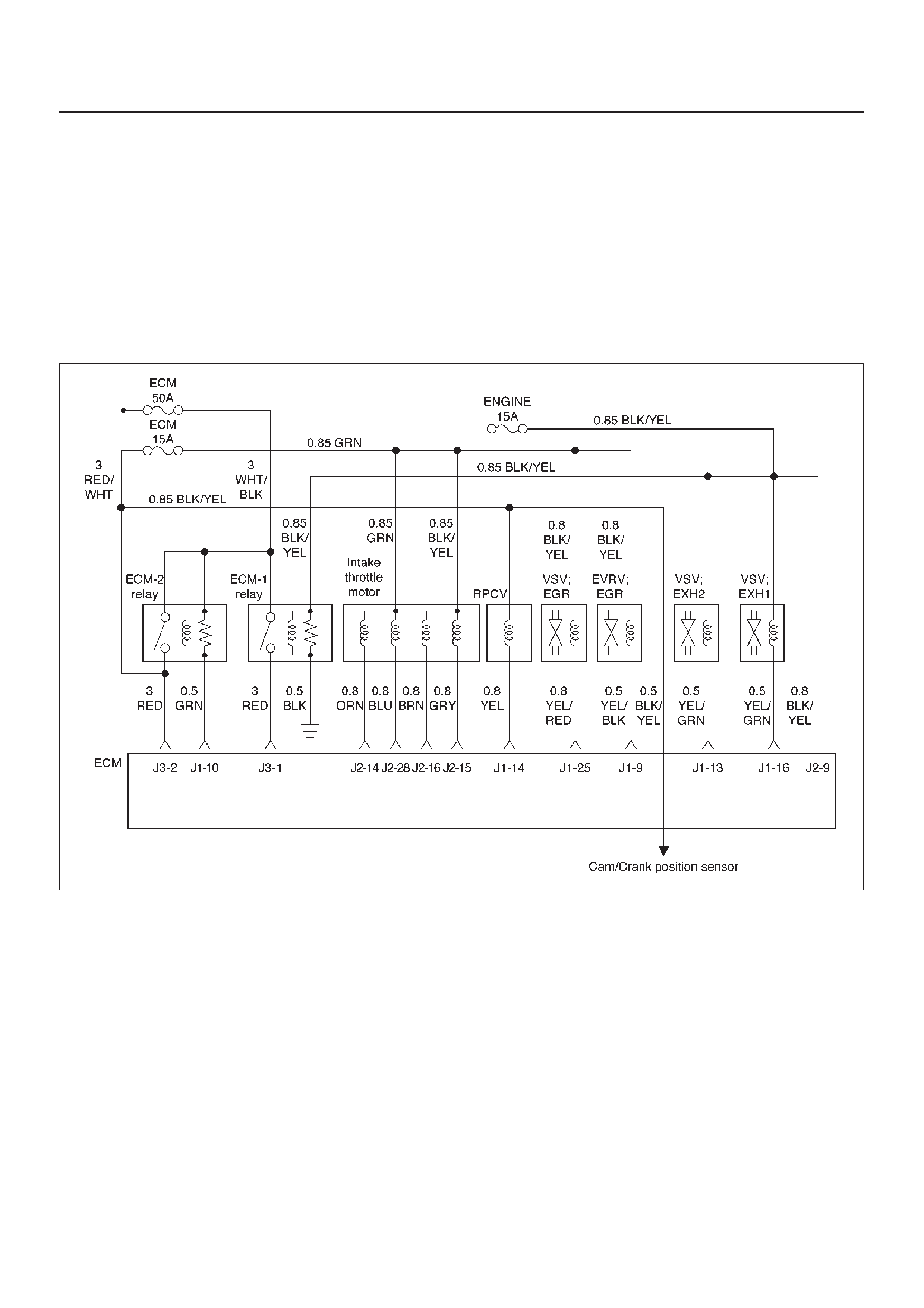
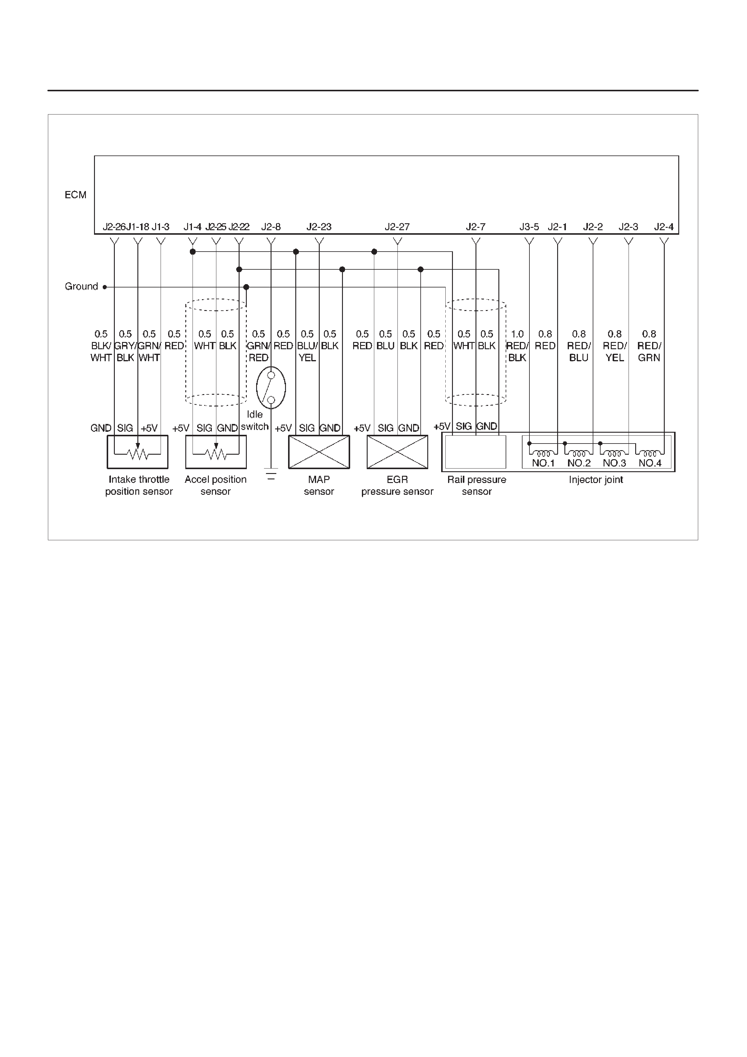
Diagrams and Schematics
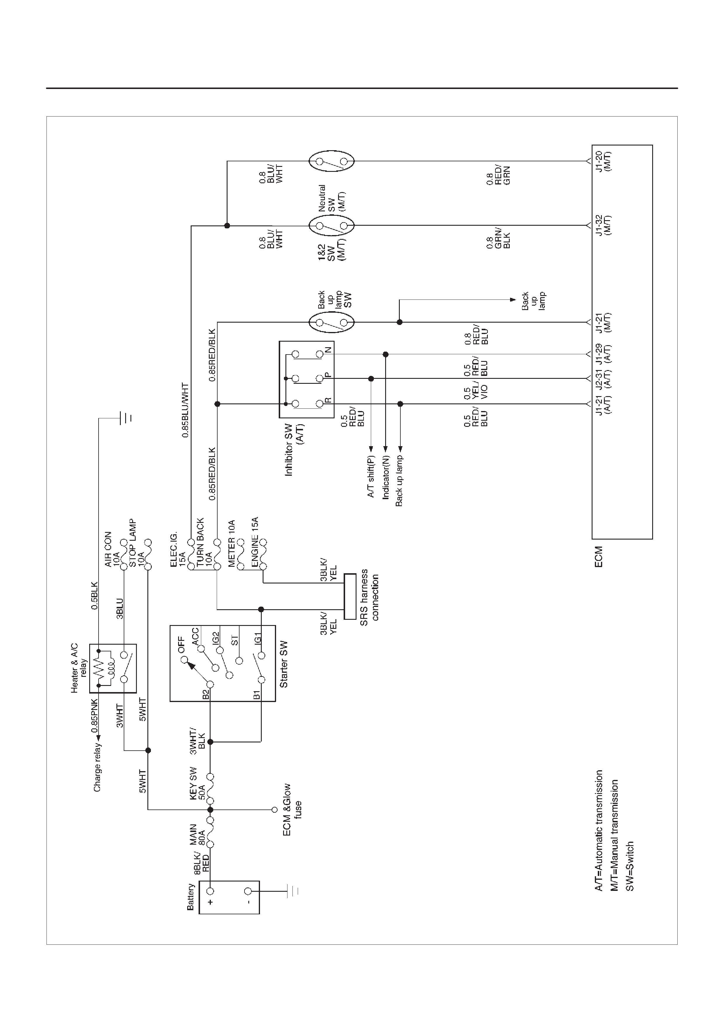
ECM Wiring Diagram (1 of 6)
060RW127
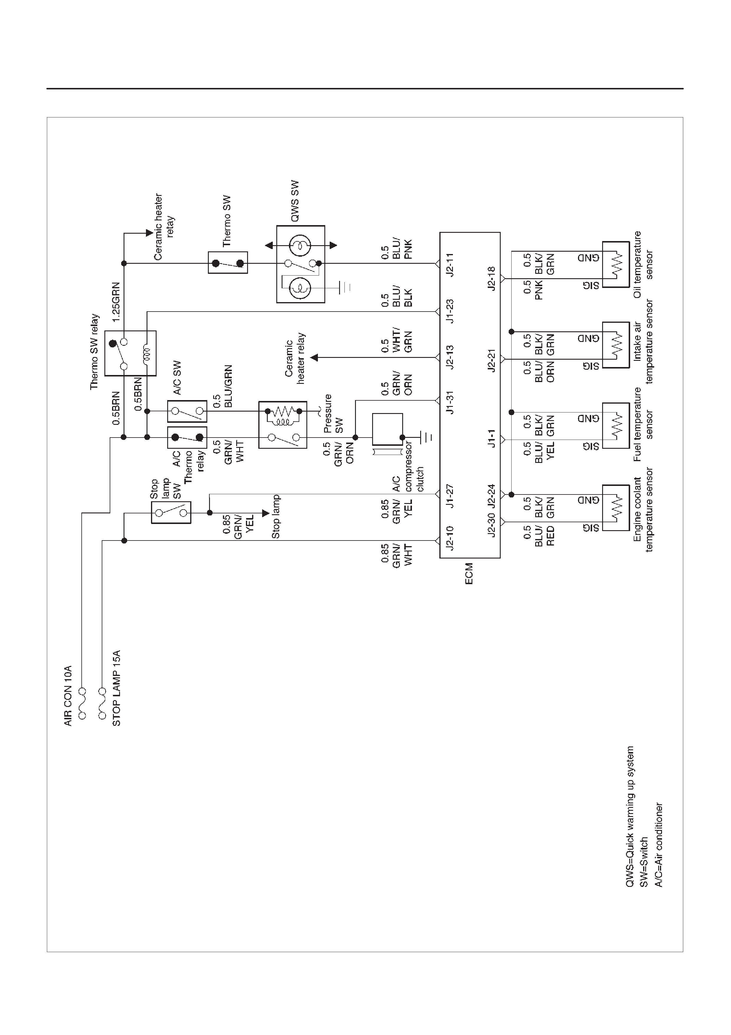
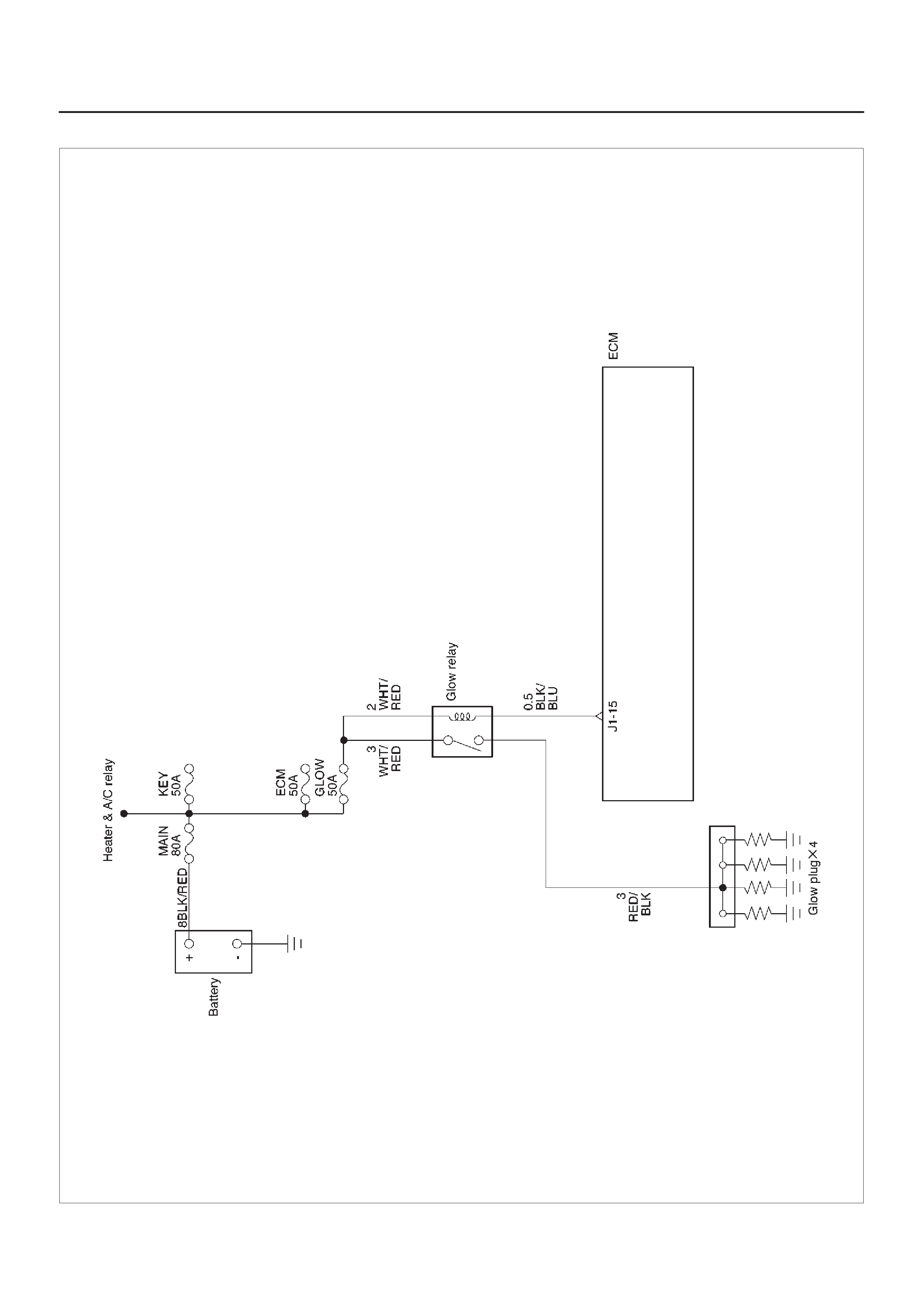
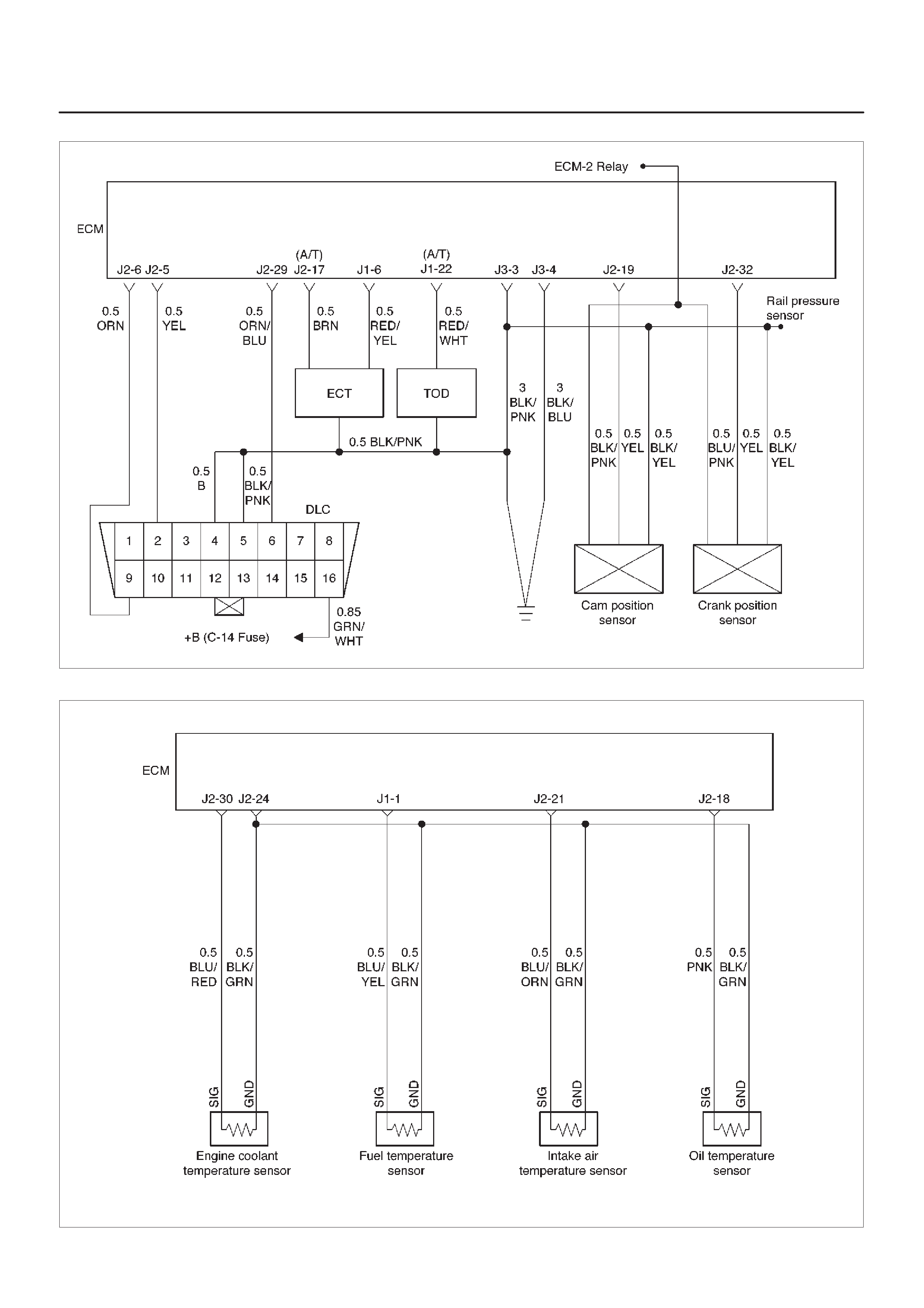
ECM Wiring Diagram (2 of 6)
060RW125
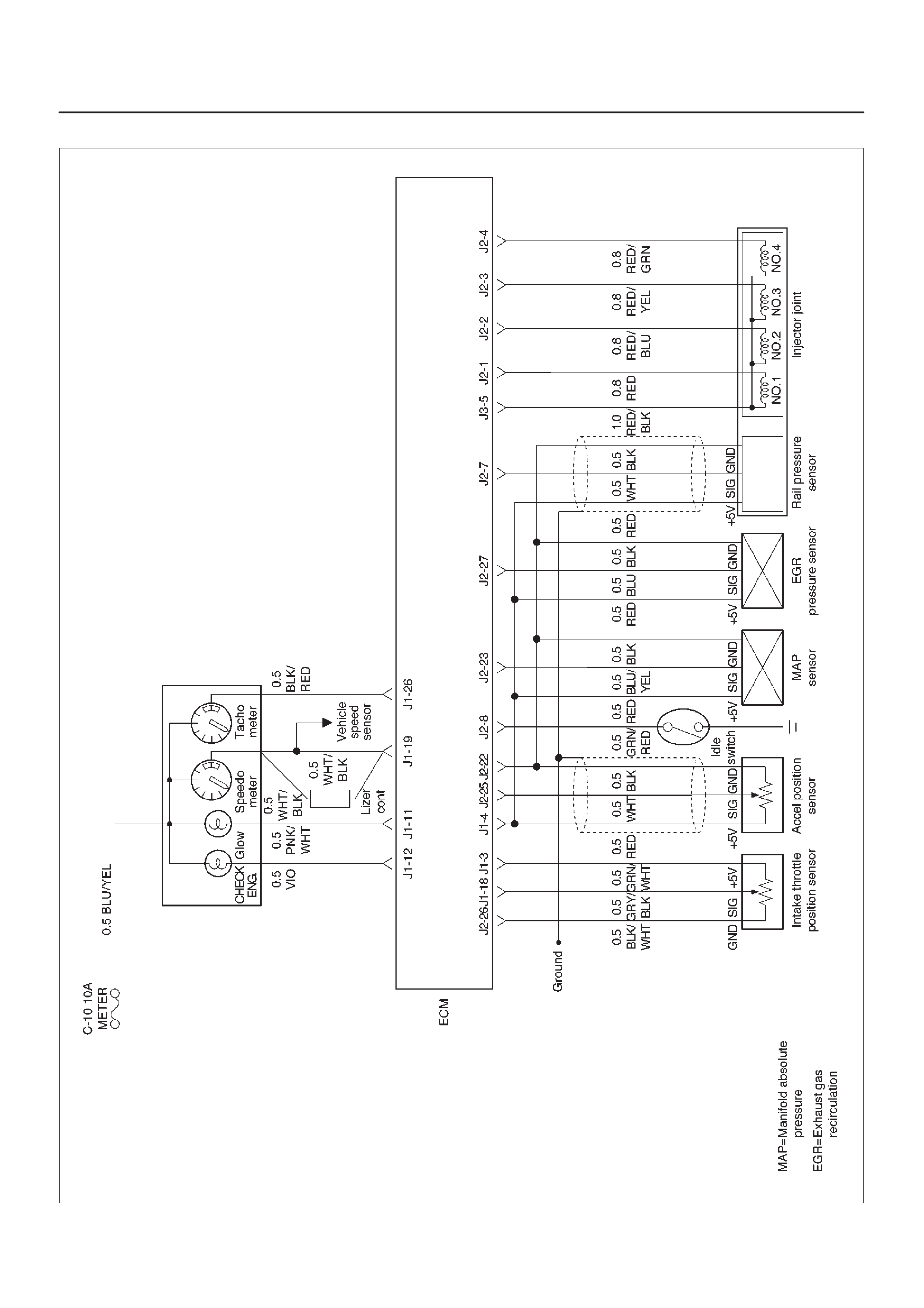
ECM Wiring Diagram (3 of 6)
060RW126
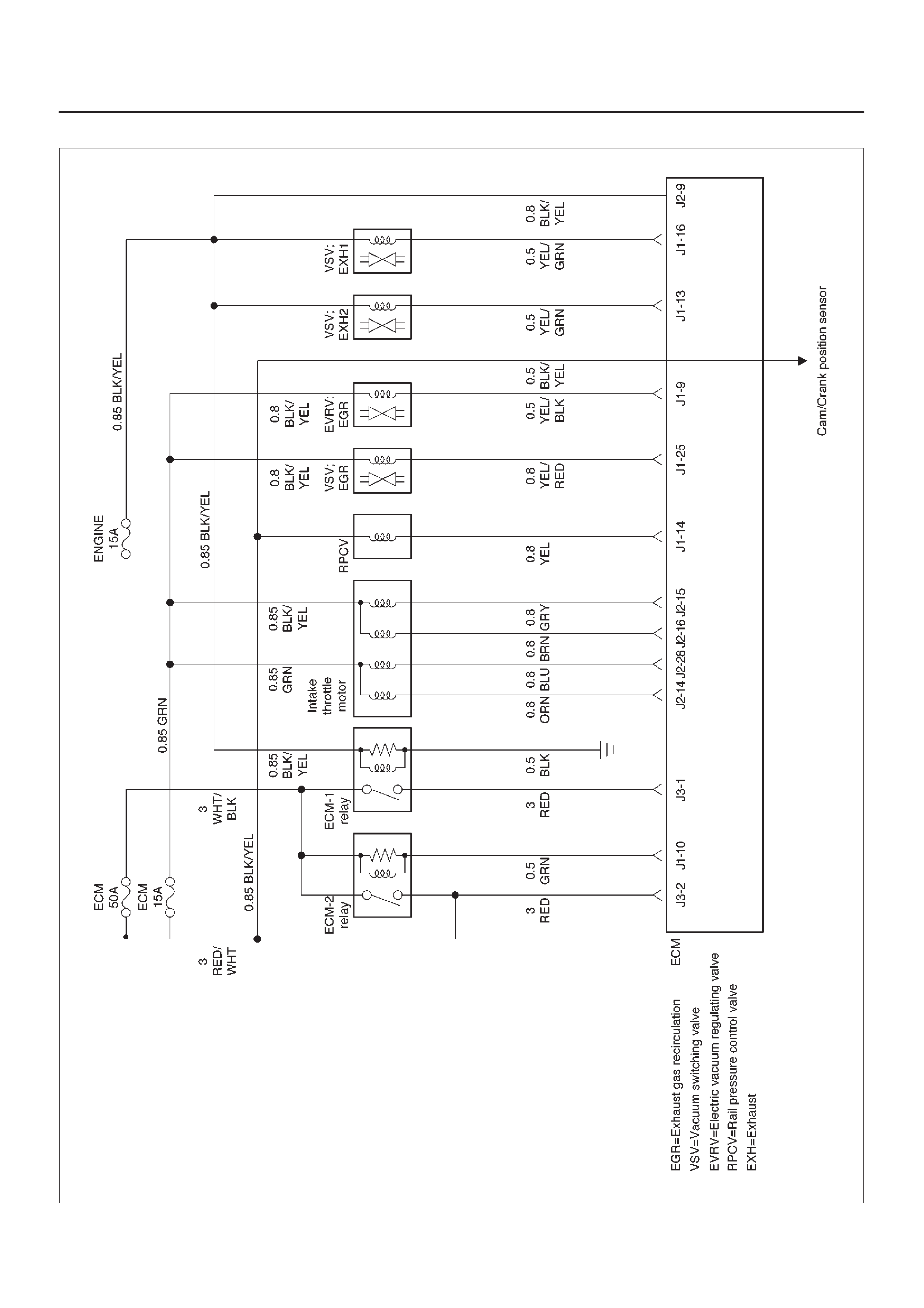
ECM Wiring Diagram (4 of 6)
060RW128
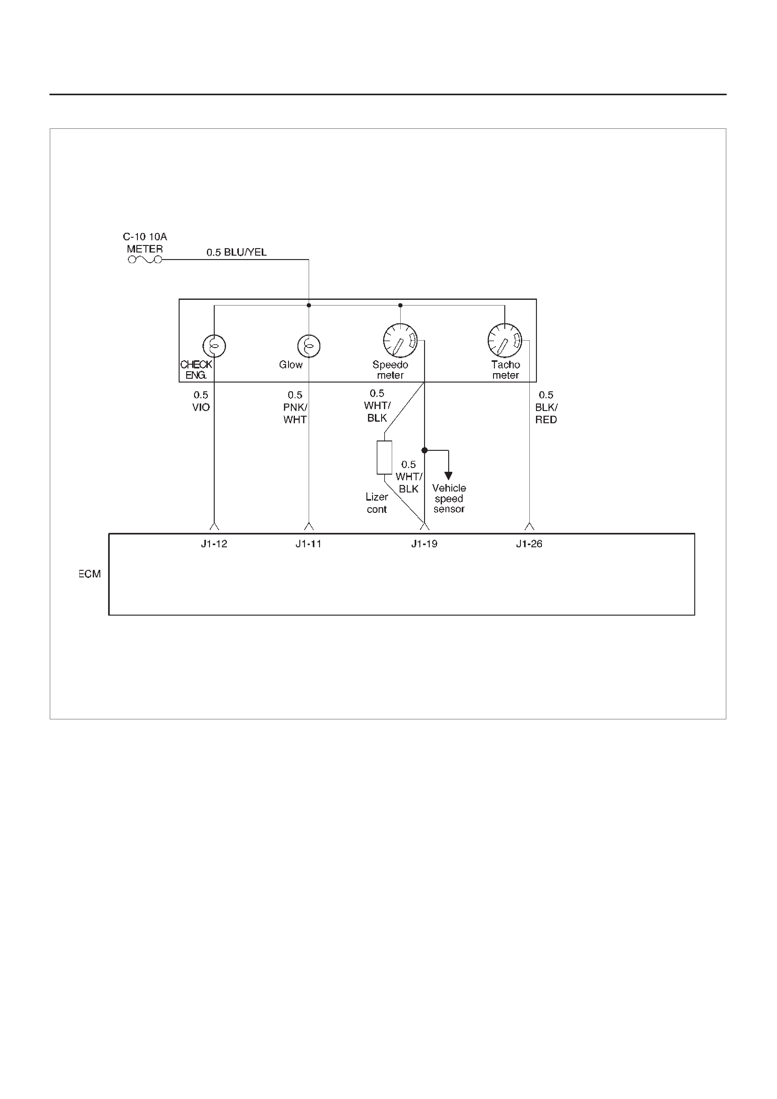
ECM Wiring Diagram (5 of 6)
060RW123
ECM Wiring Diagram (6 of 6)
060RW124
ECM Pinouts
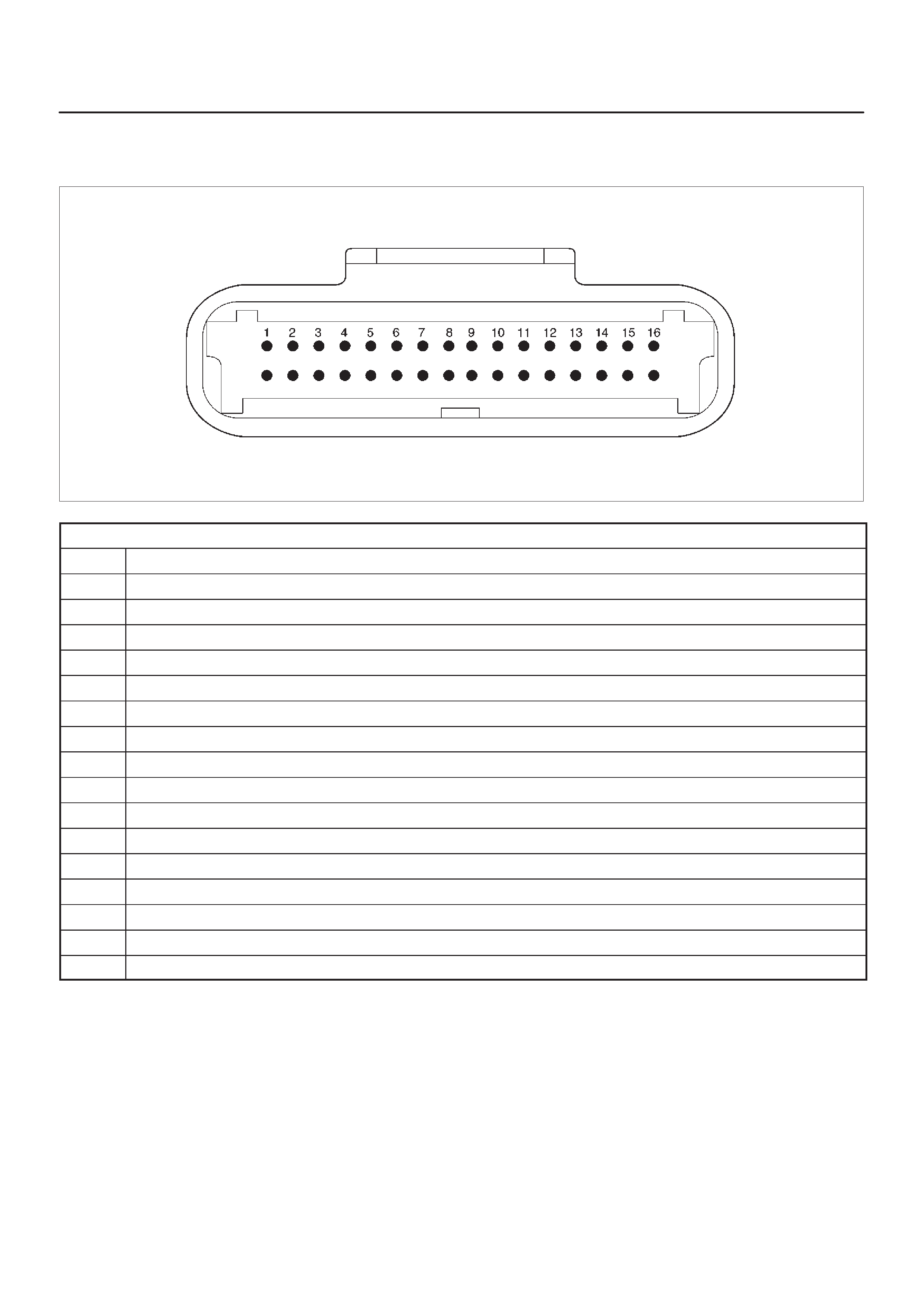
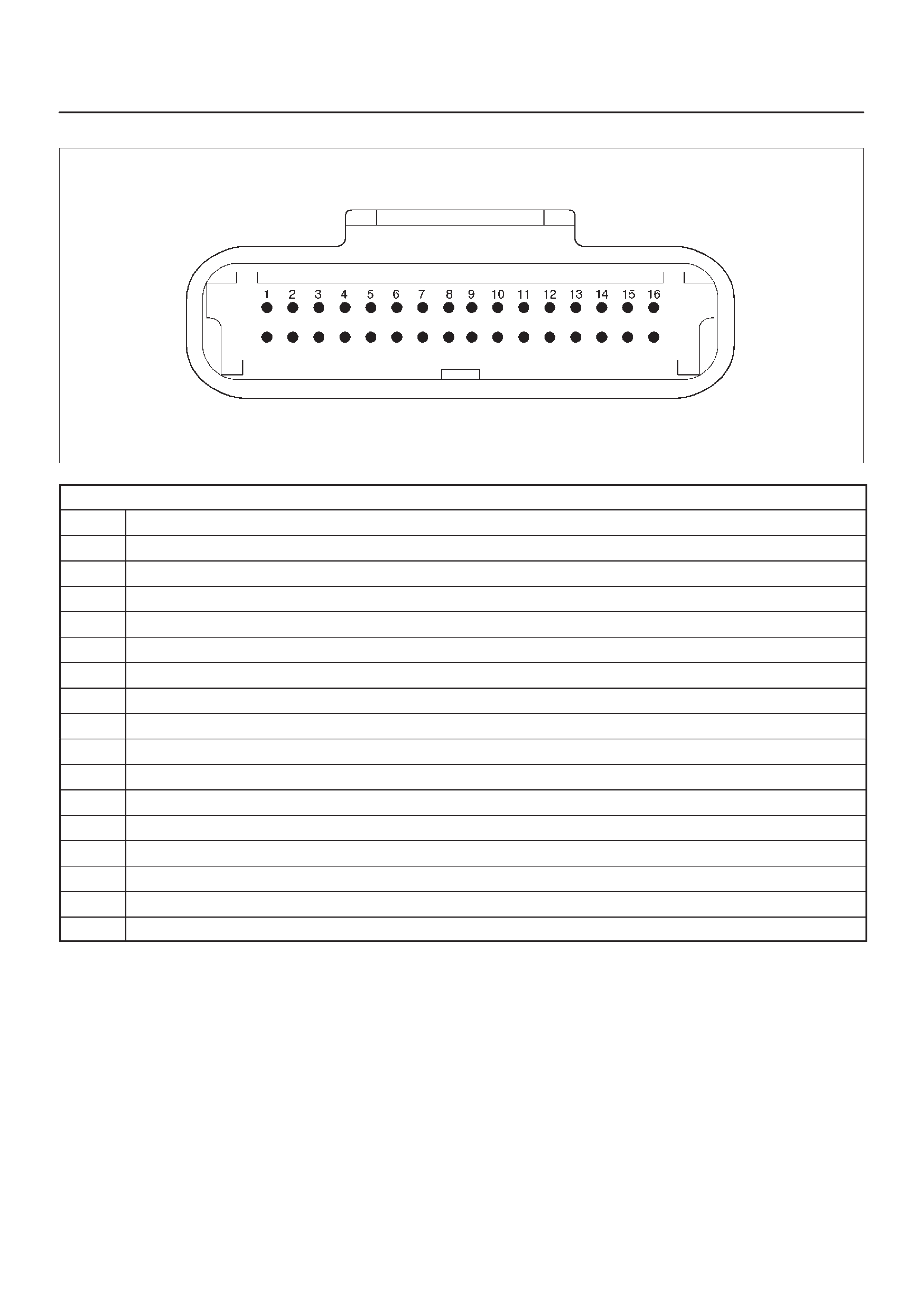
ECM Pinout Table, 32-Way Connector – J1 RED – Upper
060RW138
J1 – RED
PIN SIGNAL
1FUEL TEMPERATURE
2SPARE ANALOG 1
3 +5VB1
4 +5VB2
5SPARE ANALOG 3
6ACCEL POS OUT 1
7NOT USED
8SPARE OUT 2 (TCC)
9EVR V (EGR)
10 IGN RELAY
11 GLOW PLUG LAMP
12 DIAGNOSTIC LAMP
13 VSV (EXHAUST #2)
14 RAIL PRESS CNTRL VALVE
15 GLOW PLUG RELAY
16 VSV (EXHAUST #1)
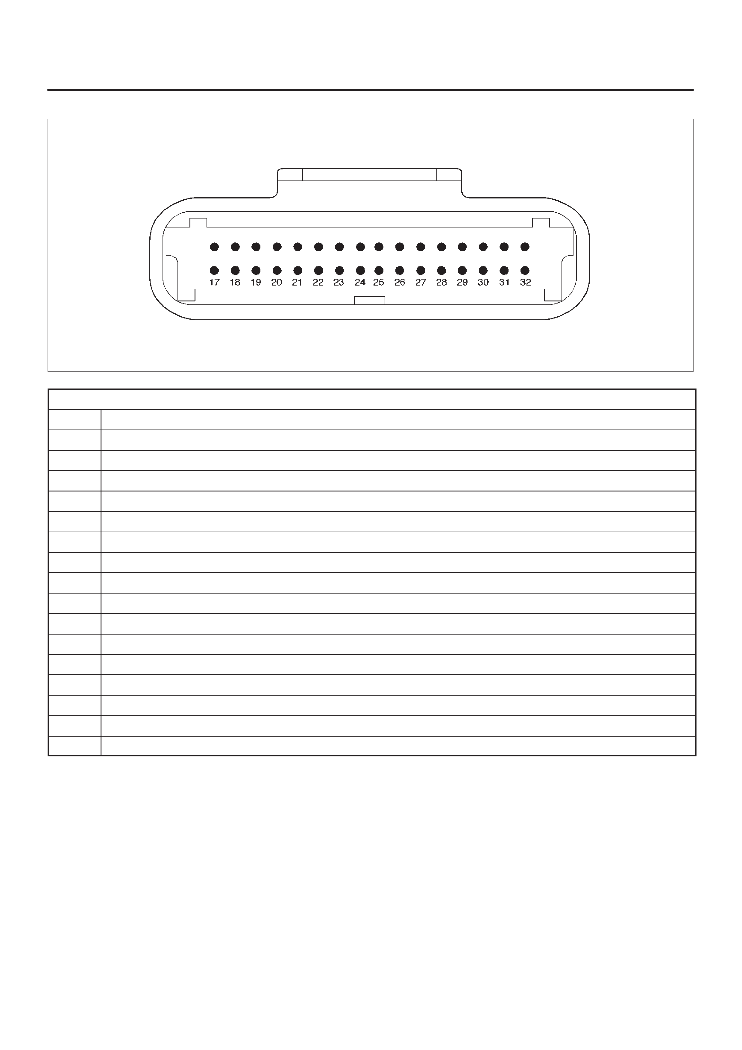
ECM Pinout Table, 32-Way Connector – J1 RED – Lower
060RW137
J1 – RED
PIN SIGNAL
17 SPARE ANALOG 4
18 INTAKE SM POSITION
19 VEHICLE SPEED
20 MT NEUTRAL
21 REVERSE SW
22 ACCEL POS OUT 2
23 THERMO SW RELAY
24 SPARE OUT 3 (TURBO)
25 VSV (EGR)
26 TACHOMETER 1
27 BRAKE SW 1
28 NOT USED (BRAKE 2)
29 A/T NEUTRAL SW
30 NO CONNECTION
31 AC REQUEST SW
32 AT SOLENOID
ECM Pinout Table, 32-Way Connector – J2 BLUE – Upper
060RW138
J2 – BLUE
PIN SIGNAL
1INJECT OR A RTN
2INJECT OR B RTN
3INJECTOR C RTN
4INJECTOR D RTN
5CLASS 2
6 SDATA
7RAIL OIL PRESSURE
8IDLE SW
9IGN SW
10 BATTERY
11 QUICK WARM REQ. SW
12 PAR TIAL IDLE SW
13 CERAMIC HTR REQUEST SW
14 INTAKE SW S2B
15 INTAKE SW S1T
16 INTAKE SW S1B

ECM Pinout Table, 32-Way Connector – J2 BLUE – Lower
060RW137
J2 – BLUE
PIN SIGNAL
17 COOLANT TEMP OUT
18 OIL TEMPERATURE
19 TDC/CAM
20 SPARE ANALOG 2
21 INTAKE AIR TEMPERATURE
22 +5VRTN2
23 BOOST/INLET PRESSURE
24 +5VRTN3
25 ACCELERATOR POSITION
26 +5VRTN1
27 EGR VACUUM PRESSURE
28 INTAKE SM S2T
29 DIAGNOSTIC REQUEST SW
30 COOLANT TEMPERATURE
31 A/T PARK SW
32 CRANKSHAFT
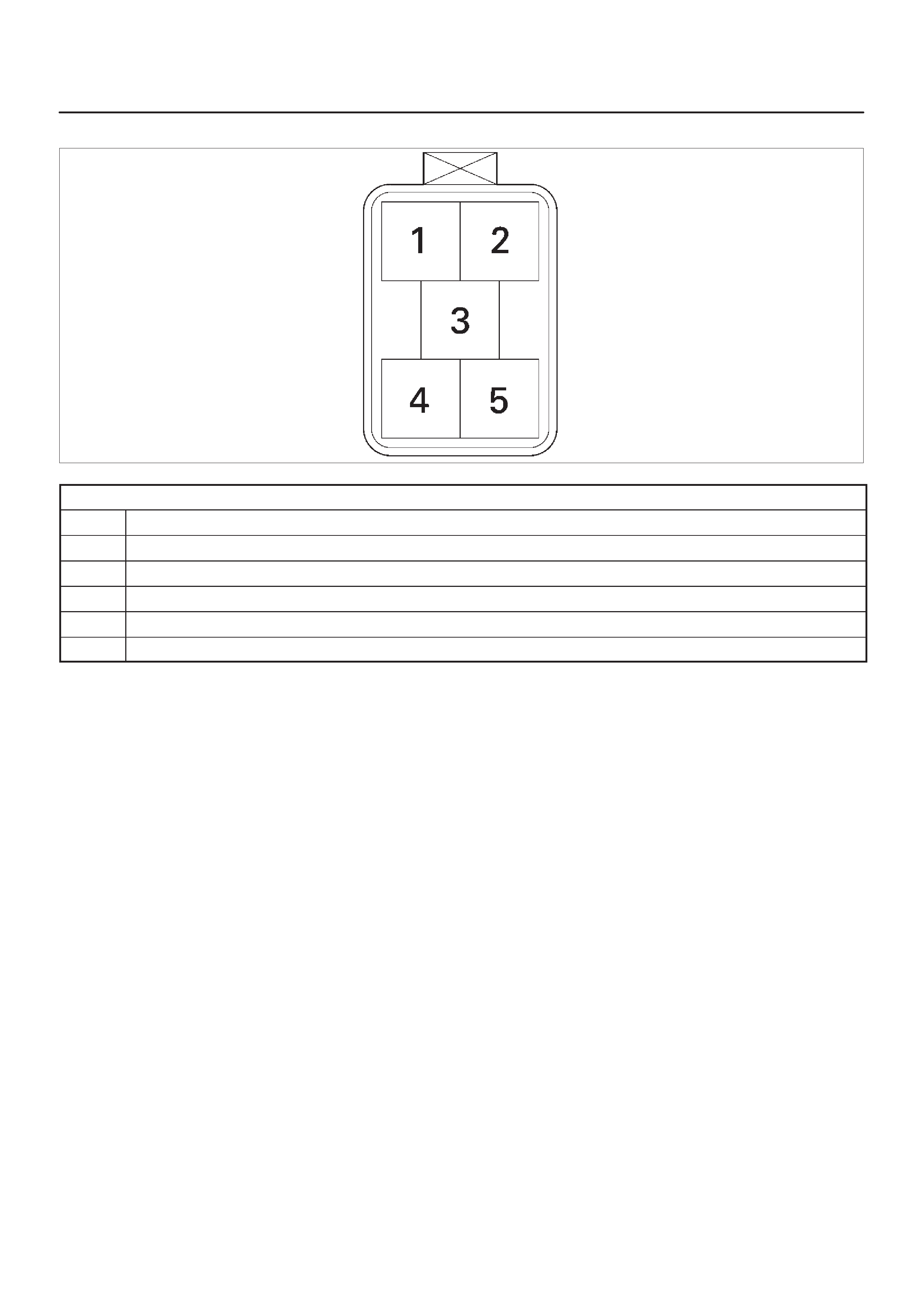
ECM Pinout Table, 5-Way Connector – J3
060RW139
J3
PIN SIGNAL
1 IGNITION
2 IGNITION
3PWR GND
4PWR GND
5INJECTOR H1

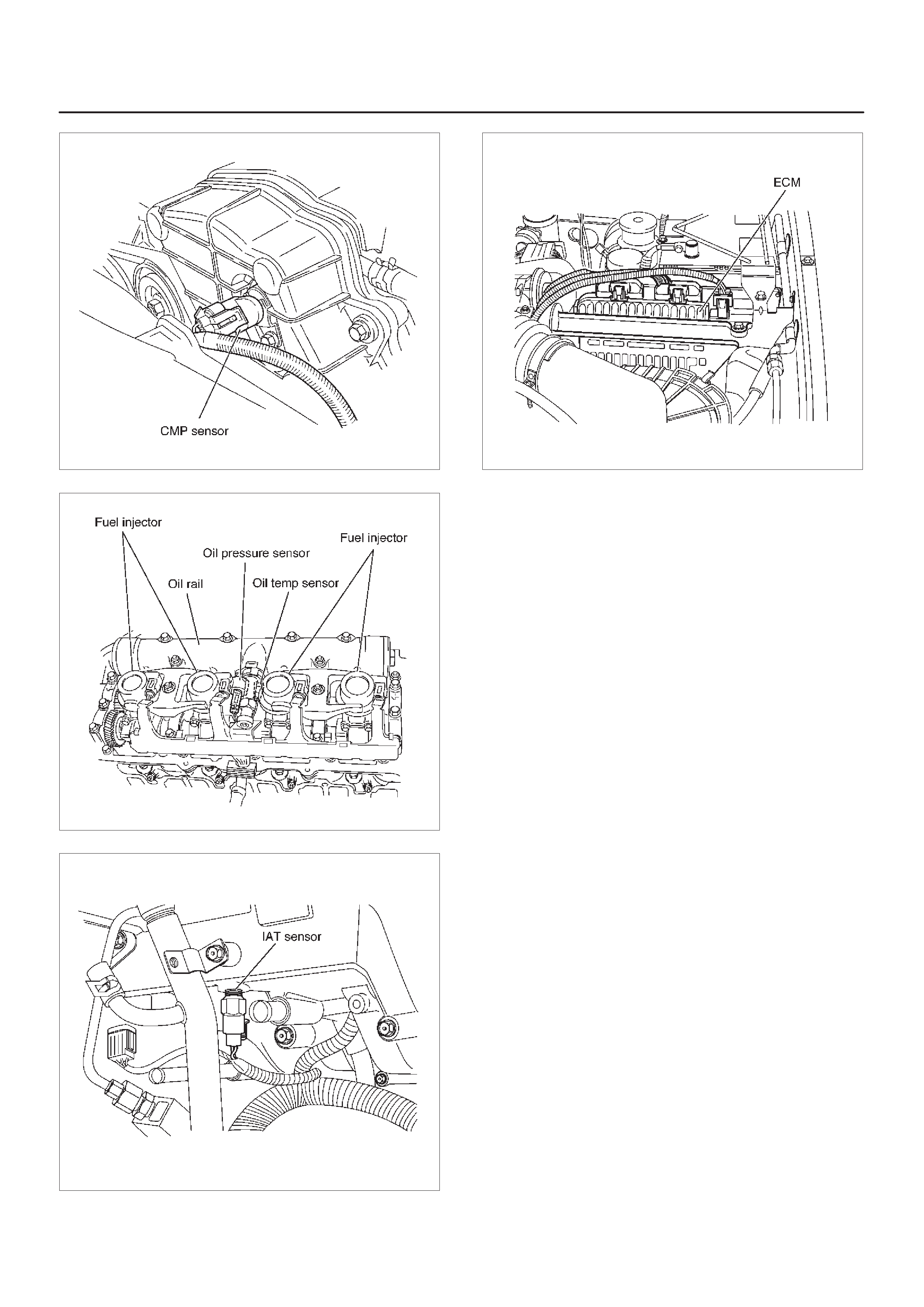
Component Locator
Engine Component Locator Table
F06RW051
Number Name Location
1AP (Accelerator Pedal Position) Sensor AP Bracket
2CKP (Crankshaft Position) Sensor Inside the right front flywheel Housing
3Oil Rail Mounted on the camshaft carrier
4Oil (Rail) Pressure Sensor Mounted on the Oil Rail
5 OT (Oil Temperature) Sensor Mounted on the Oil Rail
6Fuel Injector In the Cylinder Head Cover
7Fuel Return Orifice Inside the Cylinder Head
8 FT (Fuel Temperature) Sensor Fuel Return Adaptor
9 Intercooler On the Cylinder Head Cover
10 Intake Throttle Motor Behind the Intake Manifold
11 Intake Throttle Behind the Intake Manifold
12 2 Way Check Valve Below the Intake Manifold
13 VSV (Vacuum Switching Valve) At the left Cylinder Body
14 EGR Pressure Sensor Below the Intake Manifold
15 Fuel Filter At the left Engine Room
16 CMP (Camshaft Position) Sensor On the forward of Timing Gear Case
17 IAT (Intake Air Temperature) Sensor Below the Intake Manifold
18 ECT (Engine Coolant Temperature) Thermostat Housing
19 High Pressure Oil Pump On the back Timing Gear Case

Number Name Location
20 Rail Pressure Control Valve In the High Pressure Oil Pump
21 Fuel Pump In the High Pressure Oil Pump
22 EVR V On the Intake Manifold
23 MAP (Manifold Absolute Pressure) Sensor On the Intake Manifold
24 EGR Valve On the Intake Manifold
25 Air Cleaner At the left Engine Room
26 ECM Behind the Air Cleaner
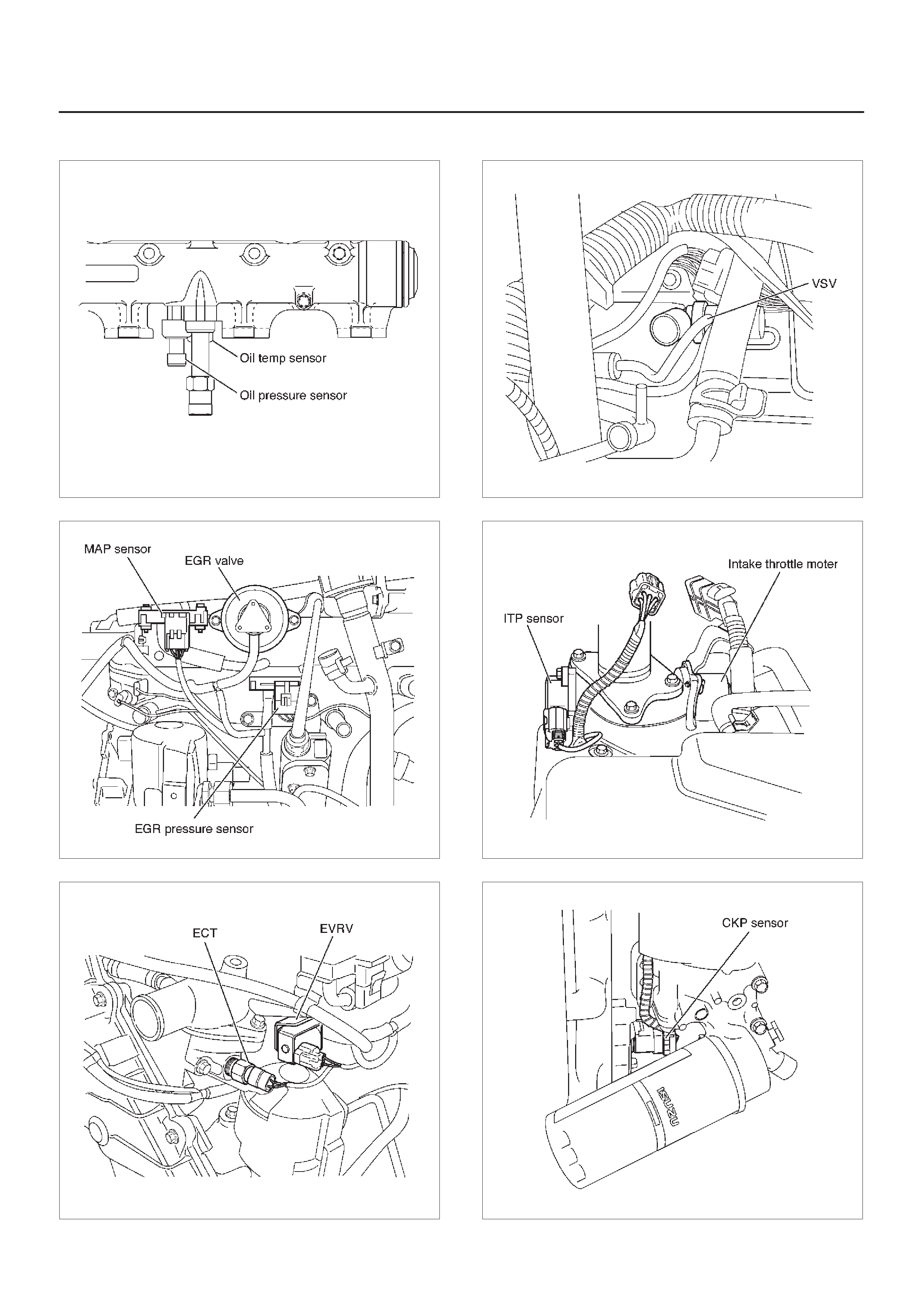
Sensors and Miscellaneous Component Locators
035RW115
035RW117
060RW179
035RW118
035RW119
035RW120
035RW121
035RW122
035RW116
035RW107

Abbreviations Charts
List of abbreviations which may be used in this section.
Abbreviations Term Abbreviations Term
A/C Air Conditioner BLK Black
A/T Automatic Transmission BLU Blue
ACC Accessory BRN Brown
AP Accel Position GRN Green
ASM Assembly GRY Gray
CKP Crank Position LT BLU Light Blue
CMP Cam Position LT GRN Light Green
DLC Data Link Connector ORN Orange
DTC Diagnosis Trouble Code PNK Pink
DVM Digital Volt Meter RED Red
ECM Engine Control Module VIO Violet
ECT Engine Coolant Temperature WHT White
EGR Exhaust Gas Recircuration YEL Yellow
EVRV Electric Vacuum Regulating Valve
EXH Exhaust
FT Fuel Temperature
IAT Intake Air Temperature
IG Ignition
ITP Intake Throttle Position
M/T Manual Transmission
MAP Manifold Absolute Pressure
MIL Mulfunction Indicator Lamp
OBD On-Board Diagnostic
OT Oil Temperature
QOS Quick on Start System
QWS Quick Warming-Up System
RP Rail Pressure
RPCV Rail Pressure Control Valve
SRS Supplemental Restraint System
ST Start
SW Switch
TEMP Temperature
TOD Torque on Demand
VSS Vehicle Speed Sensor
VSV Vacuum Switching Valve
HEUI Hydraulically Actuated Electronically Controlled Unit
Injector
I
n
j
ec
t
or

Diagnosis
Strategy-Based Diagnostics
Strategy-Based Diagnostics
The strategy-based diagnostic is a uniform approach to
repair all Electrical/Electronic (E/E) systems. The
diagnostic flow can always be used to resolve an E/E
system problem and is a starting point when repairs are
necessary. The following steps will instruct the technician
how to proceed with a diagnosis:
1.Verify the customer complaint.
DTo verify the customer complaint, the technician
should know the normal operation of the system.
2.Perform preliminary checks.
DConduct a thorough visual inspection.
DReview the service history.
DDetect unusual sounds or odors.
DGather diagnostic trouble code information to
achieve an effective repair.
3.Check bulletins and other service information.
DThis includes videos, newsletters, etc.
4.Refer to service information (manual) system
check(s).
D“System checks” contain information on a system
that may not be supported by one or more DTCs.
System checks verify proper operation of the
system. This will lead the technician in an
organized approach to diagnostics.
5.Refer to service diagnostics.
DTC Stored
Follow the designated DTC chart exactly to make an
effective repair.
No DTC
Select the symptom from the symptom tables. Follow the
diagnostic paths or suggestions to complete the repair.
You may refer to the applicable component/system check
in the system checks.
No Matching Symptom
1.Analyze the complaint.
2.Develop a plan for diagnostics.
3.Utilize the wiring diagrams and the theory of
operation.
Call technical assistance for similar cases where repair
history may be available. Combine technician knowledge
with efficient use of the available service information.
Intermittents
Conditions that are not always present are called
intermittents. To resolve intermittents, perform the
following steps:
1.Observe history DTCs, DTC modes, and freezeframe
data.
2.Evaluate the symptoms and the conditions described
by the customer.
3.Use a check sheet or other method to identify the
circuit or electrical system component.
4.Follow the suggestions for intermittent diagnosis
found in the service documentation.
Most scan tools, such as the Tech 2 and the DVM, have
data-capturing capabilities that can assist in detecting
intermittents.
No Trouble Found
This condition exists when the vehicle is found to operate
normally. The condition described by the customer may
be normal. Verify the customer complaint against another
vehicle that is operating normally. The condition may be
intermittent. Verify the complaint under the conditions
described by the customer before releasing the vehicle.
1.Re-examine the complaint.
When the complaint cannot be successfully found or
isolated, a re-evaluation is necessary. The complaint
should be re-verified and could be intermittent as
defined in
Intermittents
, or could be normal.
2.Repair and verify.
After isolating the cause, the repairs should be made.
Validate for proper operation and verify that the
symptom has been corrected. This may involve road
testing or other methods to verify that the complaint
has been resolved under the following conditions:
DConditions noted by the customer.
DIf a DTC was diagnosed, verify a repair by
duplicating conditions present when the DTC was
set as noted in the Failure Records or Freeze
Frame data.
Verifying Vehicle Repair
Verification of the vehicle repair will be more
comprehensive for vehicles with OBD system
diagnostics. Following a repair, the technician should
perform the following steps:
IMPORTANT:Follow the steps below when you verify
repairs on OBD systems. Failure to follow these steps
could result in unnecessary repairs.
1.Review and record the Failure Records and the
Freeze Frame data for the DTC which has been
diagnosed (Freeze Frame data will only be stored for
the MIL (“Check Engine” lamp) has been requested).
2.Clear the DTC(s).
3.Operate the vehicle within conditions noted in the
Failure Records and Freeze Frame data.
4.Monitor the DTC status information for the specific
DTC which has been diagnosed until the diagnostic
test associated with that DTC runs.

General Service Information
Serviceability Issues
Non-OEM Parts
All of the OBD diagnostics have been calibrated to run
with OEM parts. Accordingly , if commercially sold sensor
or switch is installed, it makes a wrong diagnosis and turn
on the MIL (“Check Engine” lamp).
Aftermarket electronics, such as cellular phones,
stereos, and anti-theft devices, may radiate EMI into the
control system if they are improperly installed. This may
cause a false sensor reading and turn on the MIL (“Check
Engine” lamp).
Poor Vehicle Maintenance
The sensitivity of OBD diagnostics will cause the MIL
(“Check Engine” lamp) to turn on if the vehicle is not
maintained properly. Restricted oil filters, fuel filters, and
crankcase deposits due to lack of oil changes or improper
oil viscosity can trigger actual vehicle faults that were not
previously monitored prior to OBD. Poor vehicle
maintenance can not be classified as a “non-vehicle
fault”, but with the sensitivity of OBD diagnostics, vehicle
maintenance schedules must be more closely followed.
Related System Faults
Many of the OBD system diagnostics will not run if the
ECM detects a fault on a related system or component.
Visual/Physical Engine Compartment
Inspection
Perform a careful visual and physical engine
compartment inspection when performing any diagnostic
procedure or diagnosing the cause of an emission test
failure. This can often lead to repairing a problem without
further steps. Use the following guidelines when
performing a visual/physical inspection:
DInspect all vacuum hoses for punches, cuts,
disconnects, and correct routing.
DInspect hoses that are difficult to see behind other
components.
DInspect all wires in the engine compartment for proper
connections, burned or chafed spots, pinched wires,
contact with sharp edges or contact with hot exhaust
manifolds or pipes.
Basic Knowledge of Tools Required
NOTE: Lack of basic knowledge of this powertrain when
performing diagnostic procedures could result in an
incorrect diagnosis or damage to powertrain
components. Do not attempt to diagnose a powertrain
problem without this basic knowledge.
A basic understanding of hand tools is necessary to effec-
tively use this section of the Service Manual.
Serial Data Communications
Class II Serial Data Communications
This vehicle utilizes the “Class II” communication system.
Each bit of information can have one of two lengths: long
or short. This allows vehicle wiring to be reduced by
transmitting and receiving multiple signals over a single
wire. The messages carried on Class II data streams are
also prioritized. If two messages attempt to establish
communications on the data line at the same time, only
the message with higher priority will continue. The device
with the lower priority message must wait.
On this vehicle the Tech 2 displays the actual values for
vehicle parameters. It will not be necessary to perform
any conversions from coded values to actual values.
On-Board Diagnostic (OBD)
On-Board Diagnostic Tests
A diagnostic test is a series of steps, the result of which is
a pass or fail reported to the diagnostic executive. When
a diagnostic test reports a pass result, the diagnostic
executive records the following data:
DThe diagnostic test has been completed since the last
ignition cycle.
DThe diagnostic test has passed during the current
ignition cycle.
DThe fault identified by the diagnostic test is not
currently active.
When a diagnostic test reports a fail result, the diagnostic
executive records the following data:
DThe diagnostic test has been completed since the last
ignition cycle.
DThe fault identified by the diagnostic test is currently
active.
DThe fault has been active during this ignition cycle.
DThe operating conditions at the time of the failure.
Comprehensive Component Monitor
Diagnostic Operation
Comprehensive component monitoring diagnostics are
required to operate engine properly.
Input Components:
Input components are monitored for circuit continuity and
out-of-range values. This includes rationality checking.
Rationality checking refers to indicating a fault when the
signal from a sensor does not seem reasonable. Accel
Position (AP) sensor that indicates high throttle position
at low engine loads or MAP voltage. Input components
may include, but are not limited to the following sensors:
DIntake Air Temperature (IAT) Sensor
DCrankshaft Position (CKP) Sensor
DIntake throttle Position (ITP) Sensor
DEngine Coolant Temperature (ECT) Sensor
DCamshaft Position (CMP) Sensor
DManifold absolute Pressure (MAP) Sensor
DAccel Position Sensor
DFuel Temp Sensor
DRail Pressure Sensor
DOil Temp Sensor
DEGR Pressure Sensor
DVehicle Speed Sensor

Output Components:
Output components are diagnosed for proper response to
control module commands. Components where
functional monitoring is not feasible will be monitored for
circuit continuity and out-of-range values if applicable.
Output components to be monitored include, but are not
limited to, the following circuit:
DEGR VSV
DEGR EVRV
DElectronic Transmission controls
DInjector
DIntake throttle
DGlow plug
DMIL control
Refer to ECM and Sensors in General Descriptions.
Passive and Active Diagnostic Tests
A passive test is a diagnostic test which simply monitors a
vehicle system or component. Conversely , an active test,
actually takes some sort of action when performing
diagnostic functions, often in response to a failed passive
test.
Intrusive Diagnostic Tests
This is any on-board test run by the Diagnostic
Management System which may have an effect on
vehicle performance or emission levels.
Warm-Up Cycle
A warm-up cycle means that engine at temperature must
reach a minimum of 70°C (160°F)
and
rise at least 22°C
(40°F) over the course of a trip.
Freeze Frame
Freeze Frame is an element of the Diagnostic
Management System which stores various vehicle
information at the moment an emissions-related fault is
stored in memory and when the MIL is commanded on.
These data can help to identify the cause of a fault. Refer
to
Storing And Erasing Freeze Fame Data
for more
detailed information.
Failure Records
Failure Records data is an enhancement of the OBD
Freeze Frame feature. Failure Records store the same
vehicle information as does Freeze Frame, but it will store
that information for any fault which is stored in on-board
memory, while Freeze Frame stores information only for
emission-related faults that command the MIL on.
Common OBD Terms
Diagnostic
When used as a noun, the word diagnostic refers to any
on-board test run by the vehicle’s Diagnostic
Management System. A diagnostic is simply a test run on
a system or component to determine if the system or
component is operating according to specification. There
are many diagnostics, shown in the following list:
DEGR
Dengine speed
Dvehicle speed
DECT
DMAP
DVSV
DIAT
DITP
DAP
DFT (Fuel Temp)
DRP (Rail Pressure)
DOT (Oil Temp)
DEGR EVRV
DIdle SW
DBrake SW
The Diagnostic Executive
The Diagnostic Executive is a unique segment of
software which is designed to coordinate and prioritize
the diagnostic procedures as well as define the protocol
for recording and displaying their results. The main
responsibilities of the Diagnostic Executive are listed as
follows:
DCommanding the MIL (“Check Engine” lamp) on and
off
DDTC logging and clearing
DFreeze Frame data for the first emission related DTC
recorded
DCurrent status information on each diagnostic
Diagnostic Information
The diagnostic charts and functional checks are designed
to locate a faulty circuit or component through a process
of logical decisions. The charts are prepared with the
requirement that the vehicle functioned correctly at the
time of assembly and that there are not multiple faults
present.
There is a continuous self-diagnosis on certain control
functions. This diagnostic capability is complemented by
the diagnostic procedures contained in this manual. The
language of communicating the source of the malfunction
is a system of diagnostic trouble codes. When a
malfunction is detected by the control module, a
diagnostic trouble code is set and the Malfunction
Indicator Lamp (MIL) (“Check Engine” lamp) is
illuminated.
Malfunction Indicator Lamp (MIL)
The Malfunction Indicator Lamp (MIL) looks the same as
the MIL you are already familiar with “Check Engine”
lamp.
Basically, the MIL is turned on when the ECM detects a
DTC that will impact the vehicle emissions.
DWhen the MIL remains “ON” while the engine is
running, or when a malfunction is suspected due to a
driveability or emissions problem, a Powertrain
On-Board Diagnostic (OBD) System Check must be
performed. The procedures for these checks are
given in On-Board Diagnostic (OBD) System Check.
These checks will expose faults which may not be
detected if other diagnostics are performed first.
DTC Types
Characteristic of Code
DNon-Emissions related
DDose not request illumination of any lamp
DStores a History DTC on the
first trip
with a fail
DStores Fail Record when test fails
DUpdates the Fail Record each time the diagnostic test
fails
Storing and Erasing Freeze Frame Data and Failure
Records
The data captured is called Freeze Frame data. The
Freeze Frame data is very similar to a single record of
operating conditions. Whenever the MIL is illuminated,
the corresponding record of operating conditions is
recorded to the Freeze Frame buffer.
Data from these faults take precedence over data
associated with any other fault. The Freeze Frame data
will not be erased unless the associated history DTC is
cleared.
Each time a diagnostic test reports a failure, the current
engine operating conditions are recorded in the
Failure
Records
buffer. A subsequent failure will update the
recorded operating conditions. The following operating
conditions for the diagnostic test which failed
typically
include the following parameters:
DEngine Speed
DEngine Load
DEngine Coolant Temperature
DVehicle Speed
DIntake Throttle Position
DMAP
DInjector Base Pulse Width
DLoop Status
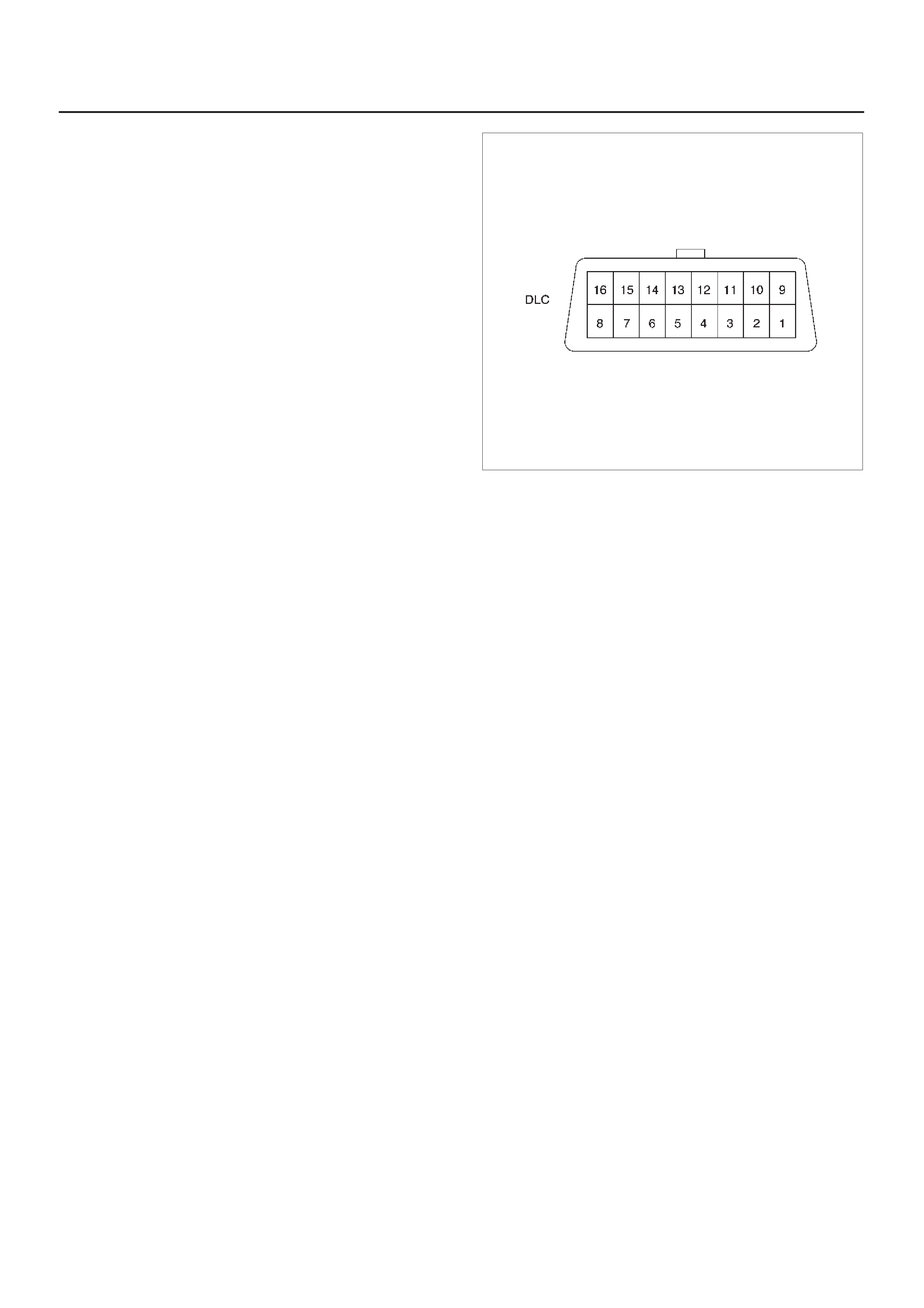
Data Link Connector (DLC)
The provision for communication with the contorl module
is the Data Link Connector (DLC). It is located at behind
the lower front instrument panel. The DLC is used to
connect to a Tech 2. Some common uses of the Tech 2
are listed below:
DIdentifying stored Diagnostic T rouble Codes (DTCs).
DClearing DTCs.
DPerforming out put control tests.
DReading serial data.
060RW046
Verifying Vehicle Repair
Verification of vehicle repair will be more comprehensive
for vehicles with OBD system diagnostic. Following a
repair , the technician should perform the following steps:
1.Review and record the Fail Records and/or Freeze
Frame data for the DTC which has been diagnosed.
2.Clear DTC(s).
3.Operate the vehicle within conditions noted in the Fail
Records and/or Freeze Frame data.
4.Monitor the DTC status information for the specific
DTC which has been diagnosed until the diagnostic
test associated with that DTC runs.
Following these steps are very important in verifying
repairs on OBD systems. Failure to follow these steps
could result in unnecessary repairs.
Reading Flash Diagnostic Trouble Codes
The provision for communicating with the Engine Control
Module (ECM) is the Data Link Connector (DLC). The
DLC is located in the front console box. It is used in the
assembly plant to receive information in checking that the
engine is operating properly before it leaves the plant.
The diagnostic trouble code(s) (DTCs) stored in the
ECM’s memory can be read either through a hand-held
diagnostic scanner plugged into the DLC or by counting
the number of flashes of the “Check Engine” Malfunction
Indicator Lamp (MIL) when the diagnostic test terminal of
the DLC is grounded. The DLC terminal “6” (diagnostic
request) is pulled “Low” (grounded) by jumpering to DLC
terminal “4”, which is a ground wire.
This will signal the ECM that you want to “flash” DTC(s), if
any are present. Once terminals “4” and “6” have been
connected, the ignition switch must be moved to the “ON”
position, with the engine not running.
The “Check Engine”MIL will indicate a DTC three times if
a DTC is present. If more than one DTC has been stored
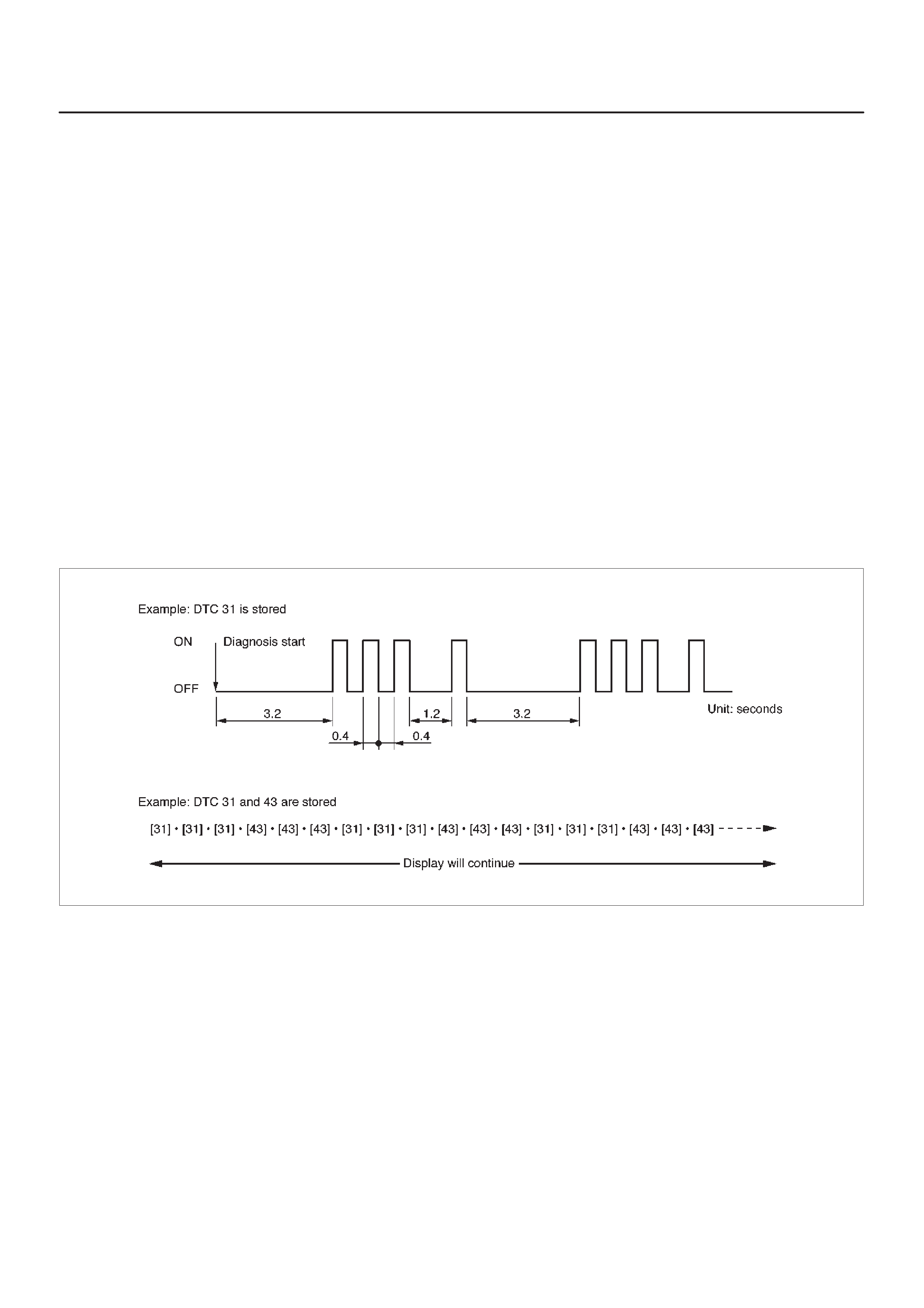
in the ECM’s memory, the DTC(s) will be output from the
lowest to the highest, with each DTC being displayed
three times.
The DTC display will continue as long as the DLC is
shorted.
Reading Diagnostic Trouble Codes Using
a TECH 2
The procedure for reading diagnostic trouble code(s) is to
used a diagnostic Tech 2. When reading DTC(s), follow
instructions supplied by Tech 2 manufacturer.
For the 1998 model year, Isuzu dealer service
departments will continue to use Tech 2.
Clearing Diagnostic Trouble Codes
IMPORTANT:Do not clear DTCs unless directed to do
so by the service information provided for each diagnostic
procedure. When DTCs are cleared, the Freeze Frame
and Failure Record data which may help diagnose an
intermittent fault will also be erased from memory.
If the fault that caused the DTC to be stored into memory
has been corrected, the Diagnostic Executive will begin to
count the “warm-up” cycles with no further faults
detected, the DTC will automatically be cleared from the
ECM memory.
To clear Diagnostic T rouble Codes (DTCs), use the Tech
2 “clear DTCs” or “clear information” function. When
clearing DTCs follow instructions supplied by the Tech 2
manufacturer.
When a Tech 2 is not available, DTCs can also be cleared
by disconnecting
one
of the following sources for at least
thirty (30) seconds.
NOTE: To prevent system damage, the ignition key must
be “OFF” when disconnecting or reconnecting battery
power.
DThe power source to the control module. Examples:
fuse, pigtail at battery ECM connectors etc.
DThe negative battery cable. (Disconnecting the
negative battery cable will result in the loss of other
on-board memory data, such as preset radio tuning).
060RW169
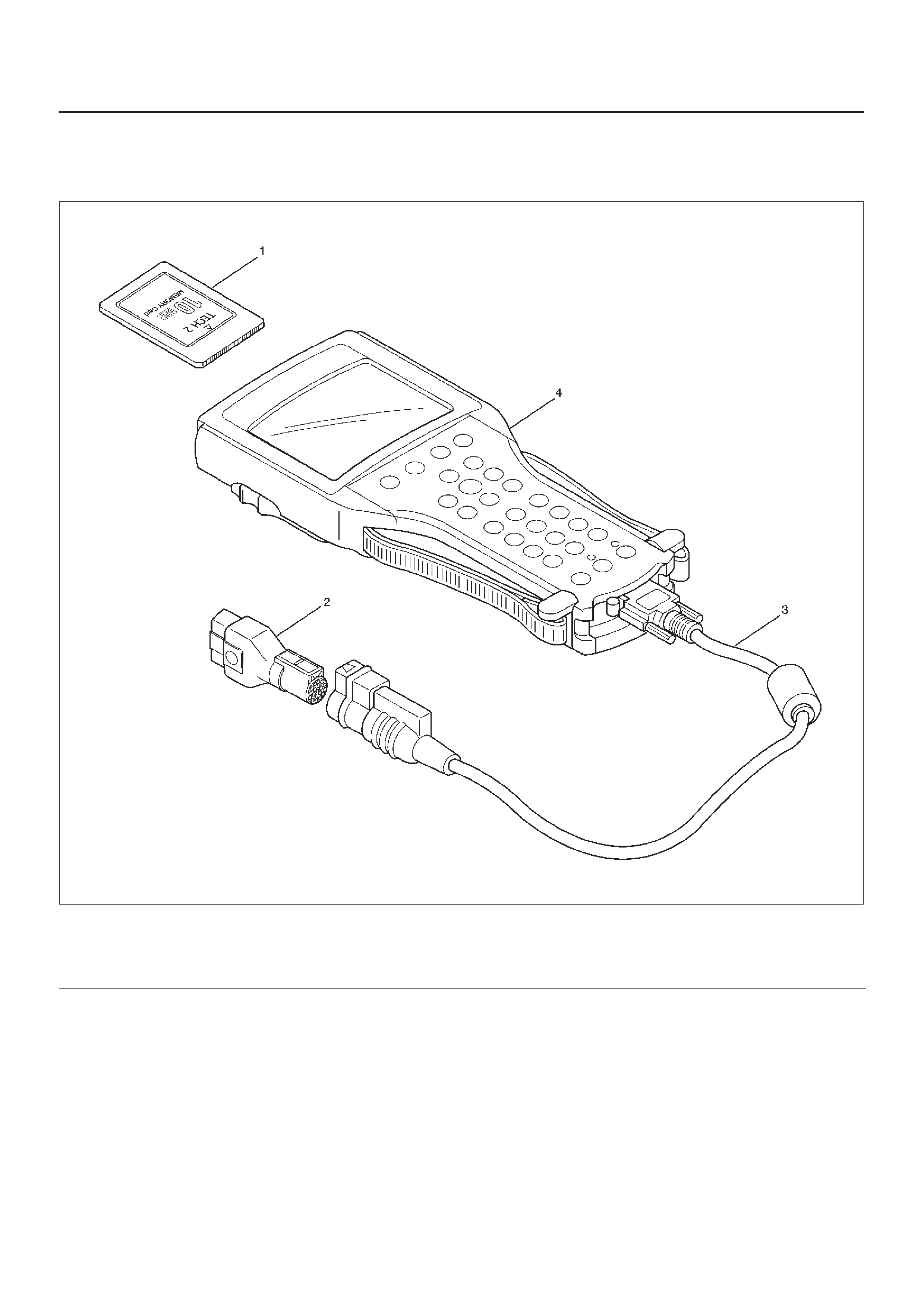
Tech 2 Scan Tool
From 98 MY, Isuzu dealer service departments are
recommended to use Tech 2. Please refer to Tech 2 user
guide.
901RW257
Legend
(1) PCMCIA Card
(2) SAE 16/19 Adaptor
(3) DLC Cable
(4) Tech–2
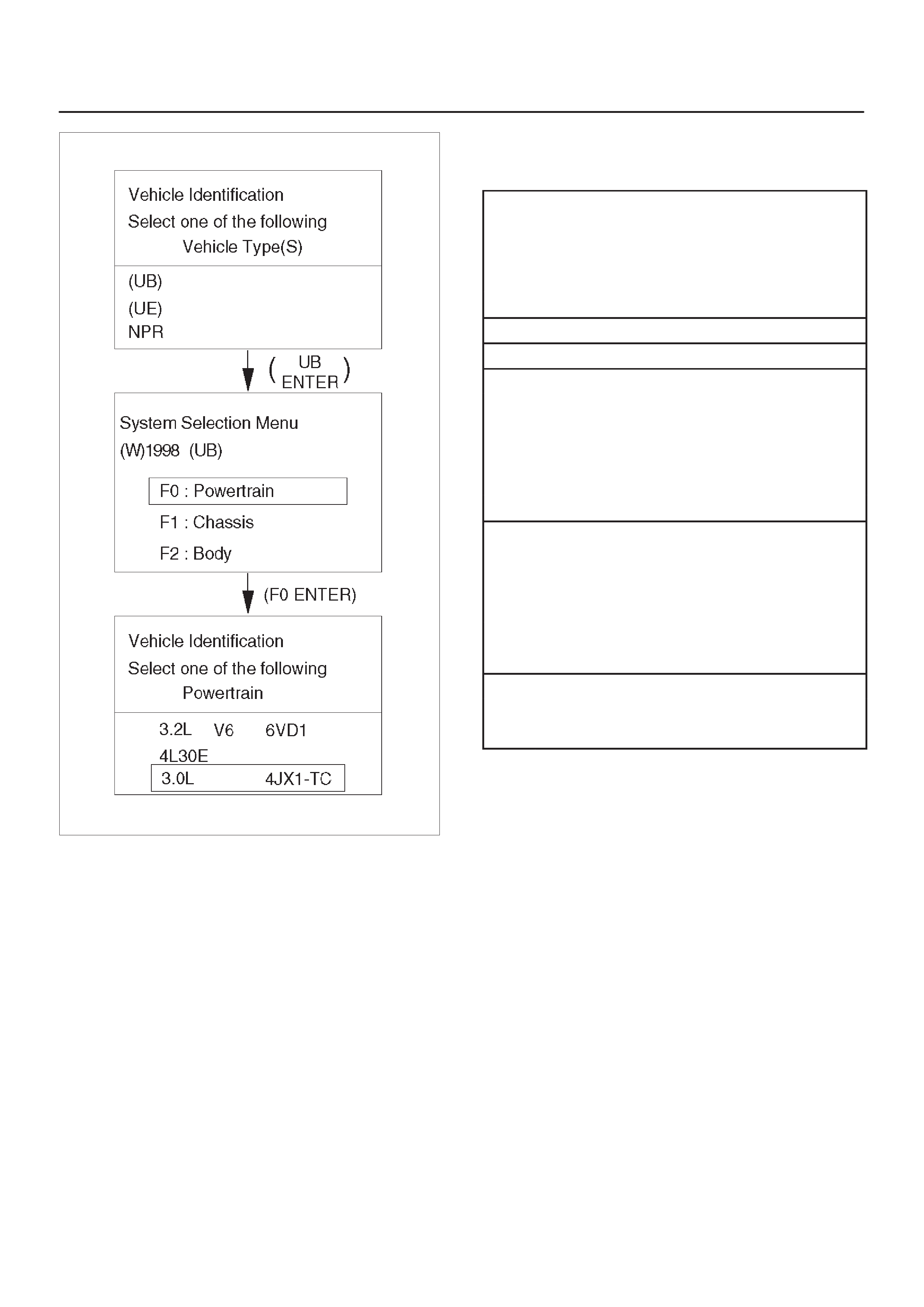
Getting Started
DBefore operating the Isuzu PCMCIA card with the
Tech 2, the following steps must be performed:
1.The Isuzu 98 System PCMCIA card (1) inserts into
the Tech 2 (5).
2.Connect the SAE 16/19 adapter (3) to the DLC cable
(4).
3.Connect the DLC cable to the Tech 2 (5)
4.Make sure the vehicle ignition is off.
5.Connect the Tech 2 SAE 16/19 adapter to the vehicle
DLC.
6.The vehicle ignition turns on.
7.Verify the Tech 2 power up display.
012RW105
NOTE: The RS232 Loop back connector is only to use for
diagnosis of Tech 2 and refer to user guide of the Tech 2.
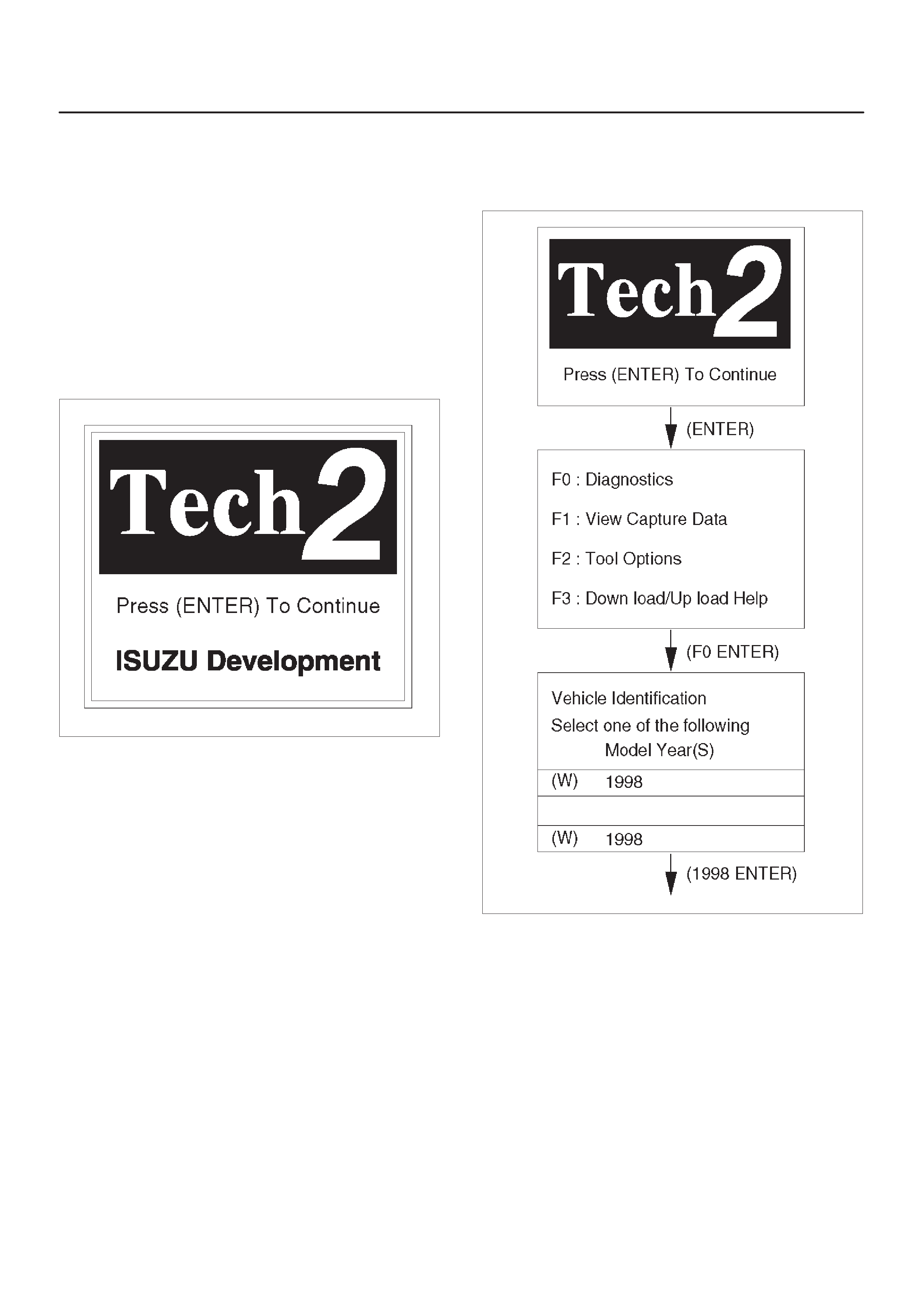
Operating Procedure
The power up screen is displayed when you power up the
tester with the Isuzu systems PCMCIA card. Follow the
operating procedure below.
060RW014
060RW120
Menu
DThe following table shows, which functions are used
the available equipment versions.
F0: Diagnostic Trouble Codes
F0: Read DTC Info Ordered By Priority
F1: Read DTC Info As Stored By ECU
F2: Clear DTC Information
F3: Freeze Frame / Failure Records
F1: Data Display
F2: Snapshot
F3: Actuator Tests
F0: Checklight
F1: Glow Time Lamp
F2: EGR Switching Valve
F3: Exhaust Switching Valve 1
F4: Exhaust Switching Valve 2
F4: Miscellaneous Tests
F0: Throttle Motor Control
F1: Rail Pressure Control
F2: EGR Regulating Valve Control
F3: Rail Pressure Control Valve
F4: Injector Balance Test
F5: Programming
F0: Injector Calibration
(F1: Rail Pressure Calibration)

DTC Modes
There are three options available in the Tech 2 DTC mode
to display the enhanced information available. A
description of the new modes, DTC Info, follows. After
selecting DTC, the following menu appears:
DDTC Info
DClear Info
DRead DTC Info Ordered By Priority
The following is a brief description of each of the sub
menus in DTC Info. The order in which they appear here is
alphabetical and not necessarily the way they will appear
on the Tech 2.
DTC Information Mode
Use the DTC info mode to search for a specific type of
stored DTC information.The service manual may instruct
the technician to test for DTCs in a certain manner.
Always follow published service procedures.
Fail This Ignition
This selection will display all DTCs that have failed during
the present ignition cycle.
History
This selection will display only DTCs that are stored in the
ECM’s history memory. It will not display Type B DTCs
that have not requested the MIL (“Check Engine” lamp). It
will display all type A and B DTCs that have requested the
MIL and have failed within the last 40 warm-up cycles. In
addition, it will display all type C and type D DTCs that
have failed within the last 40 warm-up cycles.
MIL SVC or Message Requested
This selection will display only DTCs that are requesting
the MIL. Type C and type D DTCs cannot be displayed
using this option. This selection will report type B DTCs
only after the MIL has been requested.
Test Failed Since Code Cleared
This selection will display all active and history DTCs that
have reported a test failure since the last time DTCs were
cleared.
Injector Test
This test is conducted to make it sure that appropriate
electric signals are being sent to injectors Nos. 1 – 4.
Tech–2 must be used for this test.
Test Procedure:
1.Connect Tech–2 to the vehicle DLC.
2.Set Ignition Switch to the “ON” position.
3.Select Control Test.
4.Select Injector Test.
5.Send instructions to each injector(Switch on), making
sure of injector working noise.
NOTE:If injector working noise (Clink) can hardly be
confirmed, remove the engine head cover noise
insulation.
Refer to Section 6A.
6.In the injector whose working noise has been
confirmed, its electric circuit can be regarded as
normal.
As for the injector whose working noise has not been
confirmed, its electric circuit or the injector proper is
faulty.
EGR Valve Test
This test is conducted to check EGR valve for its working.
This test needs Tech–2.
Test Procedure
1.Connect Tech–2 to vehicle DLC.
2.Switch on the engine.
3.Select “DIAGNOSIS” from the main menu.
4.Select Miscellaneous Test.
5.Select EGR Valve.
6.Instruct EGR Valve to check a data list.
7.If change in the data list shows a normal valve, the
working of EGR Valve can be judged to be normal.
Rail Pressure Control Valve Test
This test is conducted to check RPC valve for its working.
This test needs Tech–2.
Test Procedure
1.Connect Tech–2 to vehicle DLC.
2.Switch on the engine.
3.Select “DIAGNOSIS” from the main menu.
4.Select Miscellaneous Test.
5.Select Rail Pressure Control Valve.
6.Instruct RPC Valve to check a data list.
7.If change in the data list shows a normal valve, the
working of RPC Valve can be judged to be normal.
Injector Balance Test
This test is conducted to make it sure that appropriate
electric signals are being sent to injectors Nos. 1-4, when
the engine is idling.
This test needs Tech–2.
Test Procedure
1.Connect Tech–2 to vehicle DLC.
2.The engine is running at idling condition.
3.Select “DIAGNOSIS” from the main menu.
4.Select Miscellaneous Test.
5.Select the injector Balance Test.
6.Send instructions to each injector(Switch On),
making sure change of the engine vibration.
7.In the injector whose change of the vibration has been
confirmed, it’s electric circuit can be regarded as
normal.
Data Programming in Case of ECM Change
When replacing ECM, it is necessary to confirm and
record the group sign of injector beforehand. For this
confirmation.
Techline

Tech–2 must be used. After ECM change, the recorded
group sign should be programmed. Oil pressure sensor
data also should be programmed.
DGroup Sign Confirmation Procedure
1 Connect Tech–2 to vehicle DLC.
2 Turn Ignition Switch to the “ON” position.
3 Select “DIAGNOSIS” from the main menu.
4 Select programming.
5 Select Read/store Trim Data.
6 Confirm and record the group sign of injector.
DECM Change
DProgramming Procedure for Injector Group Sign
1 Connect Tech–2 to vehicle DLC.
2 Turn Ignition Switch to the “ON” position.
3 Select “DIAGNOSIS” from the main menu.
4 Select programming.
5 Select ECM change.
6 Select cylinder.
7 Program Injector Group Sign.
8 Confirm the completion of Injector programming.
DProgramming Procedure for Oil Pressure Sensor
1 Connect Tech–2 to vehicle DLC.
2 Turn Ignition Switch to the “ON” position.
3 Select “DIAGNOSIS” from the main menu.
4 Select programming.
Rail Pressure Sensor Programming
Rail pressure sensor replacement must be programmed.
This programming needs Tech–2.
Programing Procedure
1.Connect Tech–2 to vehicle DLC.
2.Turn Ignition Switch to the “ON” position.
3.Select “DIAGNOSIS” from the main menu.
4.Select Programming.
5.Select Oil Pressure Sensor change.
6.Execute Oil Pressure Sensor Program.
7.Confirm the completion of Oil Pressure Sensor
Program.
Injector Group Sign Programming (Injector
Change)
In case of Injector change, injector group sign must be
programmed.
This programming needs Tech–2.
Programing Procedure
1.Connect Tech–2 to vehicle DLC.
2.Turn Ignition Switch to the “ON” position.
3.Select “DIAGNOSIS” from the main menu.
4.Select Programming.
5.Select Injector change.
6.Select the cylinder changed.
7.Appoint and select Injector Group Sign.
8.Confirm the completion of Injector programming.
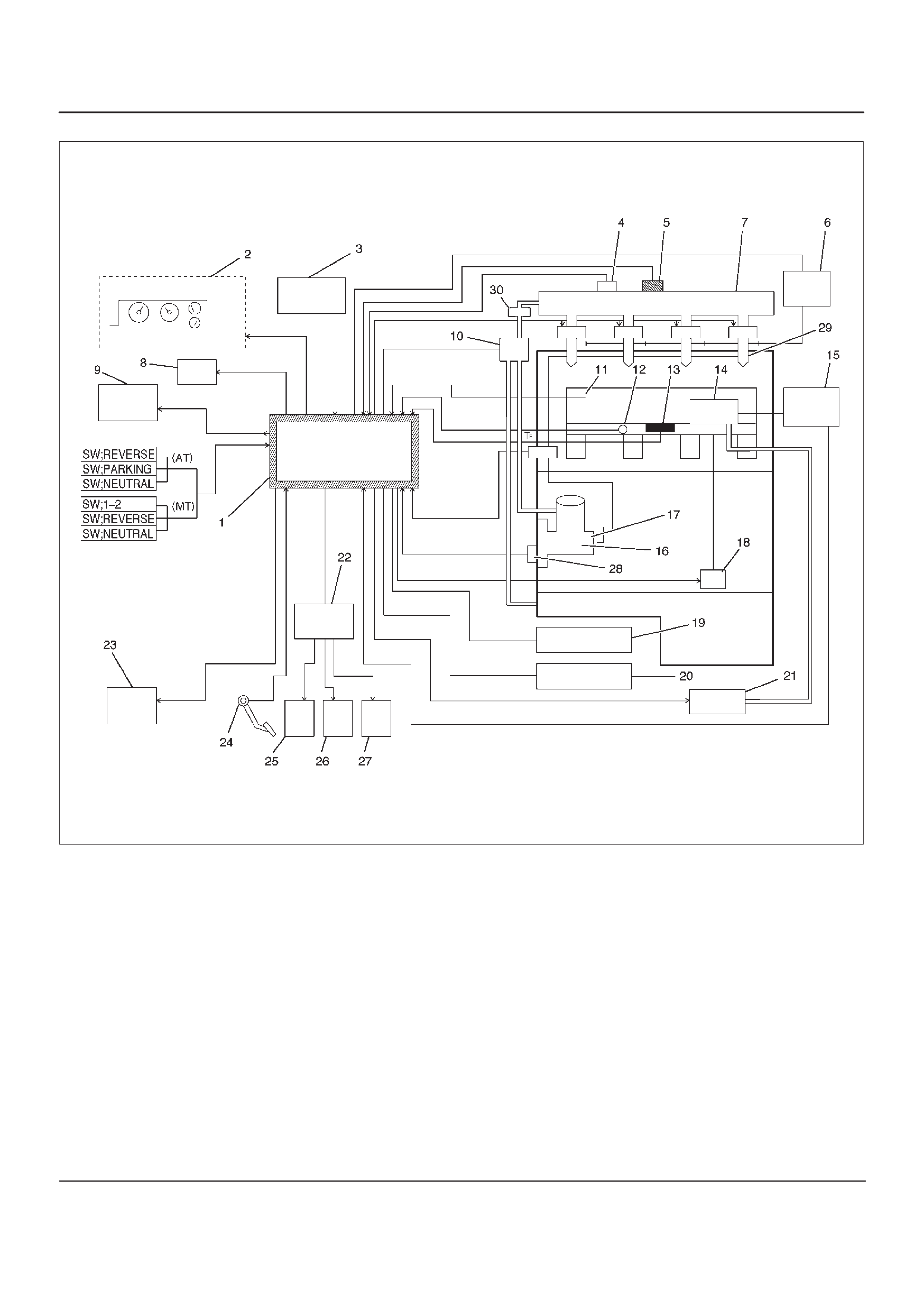
Fuel Injection System
060RW178
Legend
(1) ECM
(2) Meter Panel
(3) Battery
(4) Oil Temp Sensor
(5) Rail Pressure Sensor
(6) Glow Relay
(7) Oil Rail
(8) Tech–2
(9) A/C Comp Relay
(10) RPCV
(11) Intake Air Temp Sensor
(12) Engine Coolant Temp Sensor
(13) MAP Sensor
(14) EGR Valve
(15) EGR Pressure Sensor
(16) High Pressure Oil Pump
(17) Fuel Pump
(18) VSV
(19) EXH Throttle VSV1
(20) EXH Throttle VSV2
(21) EVRV
(22) Engine Harness Connector
(23) QWS Relay
(24) APS
(25) T.O.D
(26) ECT
(27) OBD
(28) TDC
(29) Injector
(30) Edge Filter
Guid to the System
DFuel Injection system is an HEUI (Hydraulically
Actuated, Electronically Controlled, Unit, Injector)
type. In this type of injector system, the oil
pressurized by means of High Pressure Oil Pump
(16) is fed through Rail Pressure Control Valve (10)
and Oil Rail (7) to Injector (29) from which fuel is
injected under this oil pressure.
For diagnosis, therefore, the Rail Pressure as well as
the Electric Circuit must be inspected.
On-Board Diagnostic (OBD) System Check
A Group
060RW135
B Group
060RW133
C Group
060RW129
D Group
060RW134
Circuit Description
The on-board diagnostic system check is the starting
point for any driveability complaint diagnosis. Before
using this procedure, perform a careful visual/physical
check of the ECM and engine grounds for cleanliness and
tightness.
The on-board diagnostic system check is an organized
approach to identifying a problem created by an
electronic engine control system malfunction.
Diagnostic Aids
An intermittent may be caused by a poor connection,
rubbed-through wire insulation or a wire broken inside the
insulation. Check for poor connections or a damaged
harness. Inspect the ECM harness and connector for
improper mating, broken locks, improperly formed or
damaged terminals, poor terminal-to-wire connection,
and damaged harness.
Test Description
Number(s) below refer to the step number(s) on the
Diagnostic Chart:
1. The MIL (“Check Engine” lamp) should be “ON”
steady with the ignition “ON”/engine “OFF.” If not,
Chart A-1 should be used to isolate the malfunction.
2. Checks the Class 2 data circuit and ensures that the
ECM is able to transmit serial data.
3. This test ensures that the ECM is capable of
controlling the MIL (“Check Engine” lamp) and the
MIL (“Check Engine” lamp) driver circuit is not
shorted to ground.
4. If the engine will not start, the
Cranks But Will Not
Run
chart should be used to diagnose the condition.
7. A Tech 2 parameter which is not within the typical
range may help to isolate the area which is causing
the problem.
9. When the ECM is replaced, the characteristic data of
injector and rail pressure sensor should be inputted.

On- Board Diagnostic (OBD) System Check
Step Action Value(s) Yes No
1 1. Ignition “ON,” engine “OFF.”
2. Observe the malfunction indicator lamp (MIL or
“Check Engine” lamp).
Is the MIL (“Check Engine” lamp)“ON?” —Go to
Step 2
Go to
No MIL
(“Check
Engine” lamp)
21. Ignition “OFF.”
2. Install a Tech 2.
3. Ignition “ON.”
4. Attempt to display ECM engine data with the T ech 2.
Does the Tech 2 display ECM data? —Go to
Step 3
Go to
Step 8
31. Using the Tech 2 output tests function, select MIL
(“Check Engine” lamp) dash lamp control and
command the MIL (“Check Engine” lamp) “OFF.”
2. Observe the MIL (“Check Engine” lamp).
Did the MIL (“Check Engine” lamp) turn “OFF?” —Go to
Step 4
Go to
MIL
(“Check
Engine” lamp)
On Steady
4Attempt to start the engine.
Did the engine start and continue to run? —Go to
Step 5
Go to
Cranks
But Will Not
Run
5Select “Display DTCs” with the Tech 2.
Are any DTCs stored? —Go to
Step 6
Go to
Step 7
6Are two or more of the following DTCs stored?
A Group; P0337, P0342, P1193, P1404, P1405,
P1488
B Group; P0337, P0342
C Group; P0112, P0117, P0182, P0197
D Group; P0107, P0405, P1194, P1485 —
Go to
Chart
,
“Multiple
ECM
Information
Sensor DTCs
Set”
Go to
applicable
DTC table
7Compare ECM data values displayed on the Tech 2 to
the typical engine scan data values.
Are the displayed values normal or close to the typical
values? — Go to
Step 8
Refer to
indicated
Component
System
Checks
81. Ignition “OFF,” disconnect the ECM.
2. Ignition “ON,” engine “OFF.”
3. Check the Class 2 data circuit for an open, short to
ground, or short to voltage. Also, check the DLC
ignition feed circuit for an open or short to ground
and the DLC ground circuit for an open.
4. If a problem is found, repair as necessary.
Was a problem found? —Go to
Step 2
Go to
Step 9
9Check the Tech 2 on other vehicle.
Was Tech 2 abnormal? —Go to
Step 11
Go to
Step 10
10 Replace the ECM (Refer to the Data Programming in
Case of ECM change).
Is the action complete? —Go to
Step 2
—
11 Repair the Tech 2 or prepare another Tech 2.
Is the action complete? —Go to
Step 2
—

Engine Control Module ECM
Diagnosis
To read and clear diagnostic trouble codes, use a Tech 2.
IMPORTANT:Use of a Tech 2 is recommended to clear
diagnostic trouble codes from the ECM memory.
Diagnostic trouble codes can also be cleared by turning
the ignition “OFF” and disconnecting the battery power
from the ECM for 30 seconds. Turning off the ignition and
disconnecting the battery power from the ECM will cause
all diagnostic information in the ECM memory to be
cleared. Therefore, all the diagnostic tests will have to be
re-run.
Since the ECM can have a failure which may affect only
one circuit, following the diagnostic procedures in this
section will determine which circuit has a problem and
where it is.
If a diagnostic chart indicates that the ECM connections
or the ECM is the cause of a problem, and the ECM is
replaced, but this does not correct the problem, one of the
following may be the reason:
DThere is a problem with the ECM terminal
connections. The terminals may have to be removed
from the connector in order to check them properly.
DThe problem is intermittent. This means that the
problem is not present at the time the system is being
checked. In this case, refer to the
Symptoms
portion
of the manual and make a careful physical inspection
of all components and wiring associated with the
affected system.
DThere is a shorted solenoid, relay coil, or harness.
Solenoids and relays are turned “ON” and “OFF” by
the ECM using internal electronic switches called
drivers. A shorted solenoid, relay coil, or harness will
not damage the ECM but will cause the solenoid or
relay to be inoperative.
Multiple ECM Information Sensor
DTCS Set
Circuit Description
The Engine Control Module ECM monitors various
sensors to determine the engine operating conditions.
The ECM controls fuel delivery, spark advance,
transmission operation, and emission control device
operation based on the sensor inputs.
The ECM provides a sensor ground to all of the sensors.
The ECM applies 5 volts through a pull-up resistor, and
determines the status of the following sensors by
monitoring the voltage present between the 5-volt supply
and the resistor:
DThe fuel temperature (FT) sensor
DThe engine coolant temperature (ECT) sensor
DThe Intake air temperature (IAT) sensor
The ECM provides the following sensors with a 5-volt
reference and a sensor ground signal:
DThe Intake throttle position sensor
DThe manifold absolute pressure sensor
DThe rail pressure sensor
DThe accelerator position sensor
DThe oil temperature sensor
DThe camshaft position sensor
DThe crankshaft position sensor
DThe EGR pressure sensor
The ECM monitors the signals from these sensors in
order to determine their operating status.
Diagnostic Aids
IMPORTANT:Be sure to inspect ECM and engine
grounds for being secure and clean.
A short to voltage in one of the sensor input circuits may
cause one or more of the following DTCs to be set:
DP0337
DP0342
DP1193
DP1404
DP1405
DP1488
IMPORTANT:If a sensor input circuit has been shorted
to voltage, ensure that the sensor is not damaged. A
damaged sensor will continue to indicate a high or low
voltage after the affected circuit has been repaired. If the
sensor has been damaged, replace it.
An open in the sensor ground circuit between the ECM
and the splice will cause one or more of the following
DTCs to be set:
DP0337
DP0342
DP0117
A short to ground in the 5-volt reference A or B circuit will
cause one or more of the following DTCs to be set:
DP0112
DP0117
DP0182
DP0197
An open in the 5-volt reference circuit A, between the
ECM and the splice will cause one or more of the following
DTCs to be set:
DP0107
DP0405
DP1194
DP0122
An open in the 5-volt reference circuit B, between the
ECM and the splice will cause one or more of the following
DTCs to be set:
DP1485
Check for the following conditions:
DPoor connection at ECM. Inspect the harness
connectors for backed-out terminals, improper
mating, broken locks, improperly formed or damage
terminals, and a poor terminal-to-wire connection.
DDamaged harness. Inspect the wiring harness for
damage. If the harness is not damaged, observe an
affected sensor’s displayed value on the Tech 2 with
the ignition “ON” and the engine “OFF” while you
move the connectors and the wiring harnesses
related to the following sensors:
DECT Sensor

DMAP Sensor
DCMP Sensor
DCKP Sensor
DEGR Pressure Sensor
DEGR VSV
DRPCV
DIAT Sensor
DIntake Throttle Motor
DFuel Temperature Sensor
DOil Temperature Sensor
DRail Pressure Sensor
Multiple ECM Information Sensor DTCs Set
Step Action Value(s) YesNo
1Was the “On-Board Diagnostic (OBD) System Check”
performed? —Go to
Step 2
Go to
OBD
System
Check
21. Turn the ignition “OFF,” disconnect the ECM.
2. T urn the ignition “ON,” check the 5 volt reference D
circuit for the following conditions:
DD poor connection at the ECM.
DAn open between the ECM connector and the
splice.
DD short to ground.
DD short to voltage.
Is there an open or short? —Go to
Step 3
Go to
Step 4
3Repair the open or short.
Is the action complete? — Verify repair —
4Check the sensor ground circuit for the following
conditions:
DA poor connection at the ECM or the affected
sensors.
DAn open between the ECM connector and the
affected sensors.
Is there an open or a poor connection? —Go to
Step 5
Go to
Step 6
5Repair the open or the poor connection.
Is the action complete? — Verify repair Go to
Step 6
6Replace the ECM (Refer to the Data Programming in
Case of ECM change).
Is the action complete? —
Go to
OBD
System
Check
—

EGR (Exhaust Gas Recirculation)
Diagnosis
DA diagnosis of the EGR system is covered by DTC
P1403.
DEGR VSV circuit diagnosis is covered by DTC P1404.
DEGR pressure sensor diagnosis is covered by DTC
P405 and/or P406.
DEGR EVRV circuit diagnosis is covered by DTC
P1405. Refer to the DTC charts.
Tech 2 Data Definitions and Ranges
A/C CLUTCH–Tech 2 Displays ON or OFF–
Indicates whether the A/C has commanded the A/C
clutch ON.
MAP kPa — Tech 2 Range 10-105 kPa/0.00-5.00
Volts —
The manifold absolute pressure reading is determined
from the MAP sensor signal monitored during key up and
wide open throttle (WOT) conditions. The manifold
absolute pressure is used to compensate for altitude
differences and is normally displayed around “61-104”
depending on altitude and manifold absolute pressure.
CMP ACT. COUNTER –Cam Position
DESIRED IDLE — Tech 2 Range 0-3187 RPM —
The idle speed that the ECM is commanding. The ECM
will compensate for various engine loads based on engine
coolant temperature, to keep the engine at the desired
speed.
ECT — (Engine Coolant Temperature) Tech 2
Range –40°C to 151°C (–40°F to 304°F) —
The engine coolant temperature (ECT) is mounted in the
coolant stream and sends engine temperature
information to the ECM. The ECM applies 5 volts to the
ECT sensor circuit. The sensor is a thermistor which
changes internal resistance as temperature changes.
When the sensor is cold (high resistance), the ECM
monitors a high signal voltage and interprets that as a cold
engine. As the sensor warms (decreasing resistance),
the voltage signal will decrease and the ECM will interpret
the lower voltage as a warm engine.
ENGINE RUN TIME — Tech 2 Range
00:00:00-99:99:99 Hrs:Min:Sec —
Indicates the time elapsed since the engine was started.
If the engine is stopped, engine run time will be reset to
00:00:00.
ENGINE SPEED — Range 0-9999 RPM —
Engine speed is computed by the ECM from the 57X
reference input. It should remain close to desired idle
under various engine loads with engine idling.
Air Intake Valve meter POSITION — Tech 2 Range
0-100 % —
IAT (INTAKE AIR TEMPERATURE)— Tech 2 Range
–40°C to 151°C (–40°F to 304°F) —
The ECM converts the resistance of the intake air
temperature sensor to degrees. Intake air temperature
(IAT) is used by the ECM to adjust fuel delivery and spark
timing according to incoming air density.
MAP — Tech 2 Range 10-105 kPa (0.00-4.97 Volts)—
The manifold absolute pressure (MAP) sensor measures
the change in the boost pressure.
MIL — Tech 2 Displays ON or OFF —
Indicates the ECM commanded state of the malfunction
indicator lamp.
AP — Tech 2 Range 0%-100% —
AP (Accelerator position) angle is computed by the ECM
from the AP sensor voltage. AP angle should display
“0%” at idle and “100%” at wide open throttle.
AP SENSOR — Tech 2 Range 0.00-5.00 Volts —
The voltage being monitored by the ECM on the AP
sensor signal circuit.
VEHICLE SPEED—Tech 2 Range 0-255 km/h (0-155
mph)–
The vehicle speed sensor signal is converted into km/h
and mph for display.
Typical Scan Data Values
Use the Typical Scan Data Values Table only after the
On-Board Diagnostic System Check has been
completed, no DTC(s) were noted, and you have
determined that the on-board diagnostics are functioning
properly. Tech 2 values from a properly-running engine
may be used for comparison with the engine you are
diagnosing. The typical scan data values represent
values that would be seen on a normally-running engine.
NOTE:A Tech 2 that displays faulty data should not be
used, and the problem should be reported to the Tech 2
manufacturer. Use of a faulty Tech 2 can result in
misdiagnosis and unnecessary replacement of parts.
Only the parameters listed below are referred to in this
service manual for use in diagnosis. For further
information on using the Tech 2 to diagnose the ECM and
related sensors, refer to the applicable reference section
listed below. If all values are within the typical range
described below, refer to the
Symptoms
section for
diagnosis.
Test Conditions
Engine running, lower radiator hose hot, transmission in
park or neutral, accessaries off, brake not applied and air
conditioning off.

4JX1-TC Engine (Automatic and Manual Transmission)
Tech 2
Parameter Data List Units
Displayed Typical Data
Values (IDLE) Typical Data
Values
(2500 RPM)
Refer To
Battery Voltage Engine Volts 12.5 ∼ 14.5 13 ∼ 15 General Description
Ignition Status Engine On/Off On On General Description
Ignition Relay2Engine On/Off On On General Description
Idle Switch Engine Inactive/
Active — — DTC P0510, P1510
Manifold
Absolute
Pressure
Engine KPa 96 ∼ 106 110 ∼ 150 General Description
DTC P0107, P0108
Rail Oil
Pressure Engine MPa 3.5 ∼ 5 4.5 ∼ 10 General Description
DTC P0192, P0193
Desired Rail Oil
Pressure Engine MPa 4 ∼ 5 5 ∼ 9 General Description
DTC P0192, P0193
Fuel
Temperature Engine °C (°F) 75 ∼ 85 75 ∼ 85 DTC P0182, P0183
Quick Warming
Switch Engine On/Off Off Off DTC P0380
Thermo Relay Engine On/Off — — DTC P1655
Actual EGR
Pressure Engine KPa 58 ∼ 60 M/T 63 ∼ 66
A/T 95 ∼ 105 DTC P0405, P0406
Barometric
Pressure Engine KPa 98 ∼ 102 98 ∼ 102 General Description
Relative EGR
Pressure Engine KPa –38 ∼ –45 M/T –34 ∼ –37
A/T 0 General Description
Desired EGR
Pressure Engine KPa –43 ∼ –40 M/T 36
A/T 0 General Description
Brake Switch Engine Inactive/
Active — — DTC P1588
Gear Engine — — — —
Vehicle Speed Engine Km/h 0 0 Transmission Diagnosis
Rail Pressure
Control Valve Engine % 17 ∼ 22 18 ∼ 27 DTC P1193
EGR Status Engine Disable/
Enable Enable M/T Enable
A/T Disable General Description
EGR Switching
Valve Engine On/Off — — General Description
Throttle Motor
Position Sensor Engine Volts 3.1 ∼ 3.9 0.2 ∼ 0.9 DTC P1485, P1486,
P1487
Throttle Motor
Position Engine Steps 0 ∼ 1.0 0 ∼ 1.0 DTC P1488
Delirered Fuel
Quantity Engine mm 3/st 6 ∼ 10 6 ∼ 12 General Description
Injector Status Engine Disable/
Enable Enable Enable DTC P0201, P0202,
P0203, P0204, General
Description
Injector Pulse
Width Engine ms 0.9 ∼ 1.25 0.7 ∼ 1.1 General Description
Injector Start
Offset Engine °CA — — General Description

Tech 2
Parameter Data List Units
Displayed Typical Data
Values (IDLE) Typical Data
Values
(2500 RPM)
Refer To
Exhaust VSV1 Engine On/Of f Off Off DTC P0475
Exhaust VSV2 Engine On/Of f Off Off DTC P1475
Decelevation
Fuel Cut Off Engine Inactive/
Active — — General Description
Glow Time
Lamp Engine On/Off Off Off DTC P0381
Glow Time
Relay Engine On/Off Off Off DTC P0380
Diagnostic
Request Engine Inactive
12V/
Active 0V
— — General Description
A/C Clutch Engine On/Off Off Off General Description
Desired Idle Engine RPM 720 —General Description
ECT (Engine
Coolant Temp) Engine °C (°F) 80 ∼ 90 80 ∼ 90 General Description
ECT
Engine Speed Engine RPM 720 2500 DTC P0219
MAT (Intake Air
Temp) Engine °C (°F) 65 ∼ 80 65 ∼ 80 DTC P0112, P0113
MAP KPa
(Manifold
Absolute
Pressure)
Engine Kilopascals — — General Description
DTC P0107, P0108
MIL Engine On/Off Off Off General Description
AP (Accel
Position) Engine Percent 0 8 ∼14 DTC P0121, P0122,
P0123
AP (Accel
Position) Engine Volts 0.25 ∼ 0.45 0.8 ∼ 1.0 DTC P0121, P0122,
P0123
Rail Oil
Temperature Engine °C (°F) — — DTC P0197, P0198
Desired Throttle
Motor Position Engine Steps — — —
Learned Idle
Fuel Quantity Engine mm 3/st — — —
No Malfunction Indicator Lamp (MIL)
060RW136
Circuit Description
The “Check Engine” lamp (MIL) should always be
illuminated and steady with the ignition “ON” and the
engine stopped. Ignition feed voltage is supplied to the
MIL bulb through the meter fuse. The Engine Control
Module ECM turns the MIL “ON” by grounding the MIL
driver circuit.
Diagnostic Aids
An intermittent MIL may be cause by a poor connection,
rubbed-through wire insulation, or a wire broken inside
the insulation. Check for the following items:
DInspect the ECM harness and connections for
improper mating, broken locks, improperly formed or
damaged terminals, poor terminal-to-wire
connection, and damaged harness.
DIf the engine runs OK, check for a faulty light bulb, an
open in the MIL driver circuit, or an open in the
instrument cluster ignition feed.
DIf the engine cranks but will not run, check for an open
ECM ignition or battery feed, or a poor ECM to engine
ground.
Test Description
Number(s) below refer to the step number(s) on the
Diagnostic Chart.
2. A “No MIL” condition accompanied by a no-start
condition suggests a faulty ECM ignition feed or
battery feed circuit.
9. Using a test light connected to B+, probe each of the
ECM ground terminals to ensure that a good ground
is present. Refer to
ECM Terminal End View
for
terminal locations of the ECM ground circuits.
12.In this step, temporarily substitute a known good
relay for the ECM relay. The horn relay is nearby,
and it can be verified as “good” simply by honking
the horn. Replace the horn relay after completing
this step.

No Malfunction Indicator Lamp (MIL)
Step Action Value(s) YesNo
1Was the “On-Board Diagnostic (OBD) System Check”
performed? —Go to
Step 2
Go to
OBD
System
Check
2Attempt to start the engine.
Does the engine start? —Go to
Step 3
Go to
Step 6
3Check the meter fuse for the instrument cluster ignition
feed circuit.
Is the fuse OK? —Go to
Step 4
Go to
Step 16
4Ignition “ON,” probe the ignition feed circuit at the
cluster connector with a test light to ground.
Is the test light “ON?” —Go to
Step 5
Go to
Step 13
51. Ignition “OFF.”
2. Disconnect the ECM.
3. Jumper the MIL driver circuit at the ECM connector
to ground.
4. Ignition “ON.”
Is the MIL “ON?” —Go to
Step 10
Go to
Step 11
6Check the ECM ignition feed and battery feed fuses (15
A engine fuse and 15 A ECM fuse).
Are both fuses OK? —Go to
Step 7
Go to
Step 15
71. Ignition “OFF.”
2. Disconnect the ECM.
3. Ignition “ON.”
4. Probe the ignition feed circuit at the ECM harness
connector with a test light to ground.
Is the test light “ON?” —Go to
Step 8
Go to
Step 12
8Probe the battery feed circuit at the ECM harness
connector with a test light to ground.
Is the test light “ON?” —Go to
Step 9
Go to
Step 14
9Check for a faulty ECM ground connection.
Was a problem found? — Verify repair Go to
Step 10
10 Check for damaged terminals at the ECM.
Was a problem found? — Verify repair Go to
Step 17
11 Check for an open MIL driver circuit between the ECM
and the MIL.
Was a problem found? — Verify repair Go to
Step 18
12 Substitute a known “good” relay for the ECM main
relay.
Was the malfunction fixed? — Verify repair Go to
Step 13
13 Repair the open in the ignition feed circuit.
Is the action complete? — Verify repair —
14 Locate and repair the open ECM battery feed circuit.
Is the action complete? — Verify repair —

No Malfunction Indicator Lamp (MIL) (Cont'd)
Step NoYesValue(s)Action
15 Locate and repair the short to ground in the ECM
ignition feed circuit or ECM battery feed circuit.
Is the action complete? — Verify repair —
16 Locate and repair the short to ground in the ignition
feed circuit to the instrument cluster, and replace the
fuse.
Is the action complete? — Verify repair —
17 Replace the ECM (Refer to the Data Programming in
Case of ECM change).
Is the action complete? — Verify repair —
18 Check the MIL driver circuit for a poor connection at the
instrument panel connector.
Was a problem found? — Verify repair
Go to
Instrument
Panel
in
Electrical
Diagnosis

Malfunction Indicator Lamp (MIL) “ON” Steady
060RW136
Circuit description
The “Check Engine” lamp (MIL) should always be
illuminated and steady with ignition “ON” and the engine
stopped. Ignition feed voltage is supplied directly to the
MIL indicator . The Engine Control Module ECM turns the
MIL “ON” by grounding the MIL driver circuit.
The MIL should not remain “ON” with the engine running
and no DTC(s) set. A steady MIL with the engine running
and no DTC(s) suggests a short to ground in the MIL
driver circuit.
Diagnostic Aids
An intermittent may be caused by a poor connection,
rubbed–through wire insulation, or a wire broken inside
the insulation. Check for the following items:
DPoor connection or damaged harness – Inspect the
ECM harness and connectors for improper mating,
broken locks, improperly formed or damaged
terminals, poor terminal-to-wire connection, and
damaged harness.
Test Description
Number(s) below refer to the step number(s) on the
Diagnostic Chart.
2. If the MIL does not remain “ON” when the ECM is
disconnected, the MIL driver wiring is not faulty.
3. If the MIL driver circuit is OK, the instrument panel
cluster is faulty.

Malfunction Indicator Lamp (MIL) “ON” Steady
Step Action Value(s) YesNo
1Was the “On-Board diagnostic (OBD) System Check”
performed? — Go to
Step 2
Go to
OBD
System
Check
21. Ignition “OFF,” disconnect ECM.
2. Ignition “ON,” observe the MIL (CHECK ENGINE
lamp).
Is the MIL “ON?” —Go to
Step 3
Go to
Step 5
31. Ignition “OFF,” disconnect the instrument panel
cluster.
2. Check the MIL driver circuit between the ECM and
the instrument panel cluster for a short to ground.
3. If a problem is found, repair as necessary.
Was the MIL driver circuit shorted to ground? —
Go to
OBD
System
Check
Go to
Step 4
4Replace the instrument panel cluster.
Is the action complete? —
Go to
OBD
System
Check
—
51. Ignition “OFF,” reconnect the ECM.
2. Ignition “ON,” reprogram the ECM. Refer to
On-Vehicle Service
in
Engine Control Module and
Sensor
for procedures.
3. Using the Tech 2 output controls function, select
MIL dash lamp control and command the MIL
“OFF.”
Did the MIL turn “OFF?” —
Go to
OBD
System
Check
Go to
Step 6
6Replace the ECM (Refer to the Data Programming in
Case of ECM change).
Is the action complete? —
Go to
OBD
System
Check
—

Engine Cranks But Will Not Run
Circuit Description
In this type of injector system, the Engine Control Module
(ECM) triggers the correct driver inside the injector, which
then triggers the correct injector based on the 57X signal
received from the crankshaft position sensor (CKP).
During crank, the ECM monitors the CKP 57X signal. The
CKP signal is used to determine which cylinder will fire
first. After the CKP 57X signal has been processed by the
ECM, it will command all four injectors to allow a priming
shot of fuel for all the cylinders. After the priming, the
injectors are left “OFF” during the next four 57X reference
pulses from the CKP. This allows each cylinder a chance
to use the fuel from the priming shot. During this waiting
period, a camshaft position (CMP) signal pulse will have
been received by the ECM. The CMP signal allows the
ECM to operate the injectors sequentially based on
camshaft position. If the camshaft position signal is not
present at start-up, the ECM will begin sequential fuel
delivery with a 1-in-4 chance that fuel delivery is correct.
The engine will run without a CMP signal, but will set a
DTC code.
Diagnostic Aids
An intermittent problem may be caused by a poor
connection, rubbed-through wire insulation or a wire
broken inside the insulation. Check for the following
items:
DPoor connection or damaged harness – Inspect the
ECM harness and connectors for improper mating,
broken locks, improperly formed or damaged
terminals, poor terminal-to-wore connection, and
damaged harness.
DFaulty engine coolant temperature sensor – Using a
Tech 2, compare engine coolant temperature with
manifold air temperature on a completely cool engine.
Test Description
Number(s) below refer to the step number(s) on the
Diagnostic Chart.
4. An obvious cause of low fuel pressure would be an
empty fuel tank.
5. The engine will easily start and run if a few injectors
are disabled. It is not necessary to test all injectors
at this time since this step is only a test to verify that
all of the injectors have not been disabled by fuel
contamination.
8.If there is an open or shorted driver circuit, DTCs
0201-0204 should be set.
Engine Cranks But Will Not Run
Step Action Value(s) YesNo
1Was the “On-Board Diagnostic (OBD) System Check”
performed? —Go to
Step 2
Go to
OBD
System
Check
2Check the 15 A injector fuse, the 15 A engine device
fuse, and the 15A ECM fuse.
Was a fuse blown? —Go to
Step 3
Go to
Step 4
3Check for a short to ground and replace the fuse.
Is the action complete? — Verify repair —
4Is fuel tank empty? —Fill the fuel
tank Go to
Step 5
5Is the right fuel using? —Go to
Step 6
Replace the
fuel
6Is the right engine oil using? —Go to
Step 7
Replace the
engine oil
7Using the Tech–2.
Is DTC P0192 or P0193 set? (Check rail pressure
system) —
Go to
DTC
P0192 or
DTC P0193
Go to
Step 8
8Using the Tech–2.
Is DTC P0201 – P0204 set? (Check inject circuit fault) —
Go to
DTC
P0201 –
P0204
Go to
Step 9
9Using the Tech–2.
Is DTC P1657 set? (Check ECM Main relay) —Go to
DTC
P1657
Go to
Step 10
Techline
Techline

Engine Cranks But Will Not Run (Cont'd)
Step NoYesValue(s)Action
10 Refer to
Engine Mechanical Diagnosis
to diagnose the
following conditions:
DFaulty camshaft drive belts
DLeaking or sticky valves or rings
DExcessive valve deposits
DWeak valve springs
DIncorrect valve timing
DLeaking head gasket
Is the action complete? — Verify repair Go to
Step 11
11 Observe the “Engine Speed” data display on the T ech 2
while cranking the engine.
Is the engine RPM indicated? (If the Tech 2 is normally
powered from the cigarette lighter socket, and if the
Tech 2 display goes blank while cranking the engine, it
will be necessary to power the Tech 2 directly from the
vehicle battery.) —Go to
Step 12
Go to
Step 17
12 1. At the ECM (female) side of the connector
mentioned in step, connect a test light between the
ignition + terminal and one of the injector driver
circuits at the same connector.
2. Ignition “ON.”
3. Observe the test light, and repeat the test for each
injector driver circuit by oscilloscope.
Did the test light stay on when checking any of the 4
injector driver circuits? —Go to
Step 13
Go to
Step 15
13 1. Ignition “OFF,” disconnect the ECM.
2. Ignition “ON,” observe the test light.
Is the test light “ON?” —Go to
Step 14
Go to
Step 16
14 Locate and repair the short to ground in the injector
driver circuit.
Is the action complete? — Verify repair —
15 Check for an open injector driver circuit.
Was a problem found? — Verify repair Go to
Step 16
16 Replace the ECM (Refer to the Data Programming in
Case of ECM change).
Is the action complete? — Verify repair —
17 1. Raise the vehicle and disconnect the CKP sensor
harness.
2. Ignition “ON.”
3. With a test light to ground, probe the harness
ignition feed terminal.
Did the light illuminate? —Go to
Step 19
Go to
Step 18
18 Check the ignition feed wire between the sensor and
the ECM for a short to ground or open circuit.
Is the action complete? — Verify repair —

Engine Cranks But Will Not Run (Cont'd)
Step NoYesValue(s)Action
19 1. Ignition “ON.”
2. At the CKP harness connector, connect a test light
between the ignition and ground terminals.
Did the light illuminate? —Go to
Step 21
Go to
Step 20
20 Check the sensor ground circuit for an open or short to
voltage.
Is the action complete? — Verify repair —
21 Check the signal circuit between the sensor and the
ECM for a short to ground, short to voltage, or an open.
Was a problem found? — Verify repair Go to
Step 22
22 Replace the CKP sensor.
Is the action complete? — Verify repair Go to
Step 16
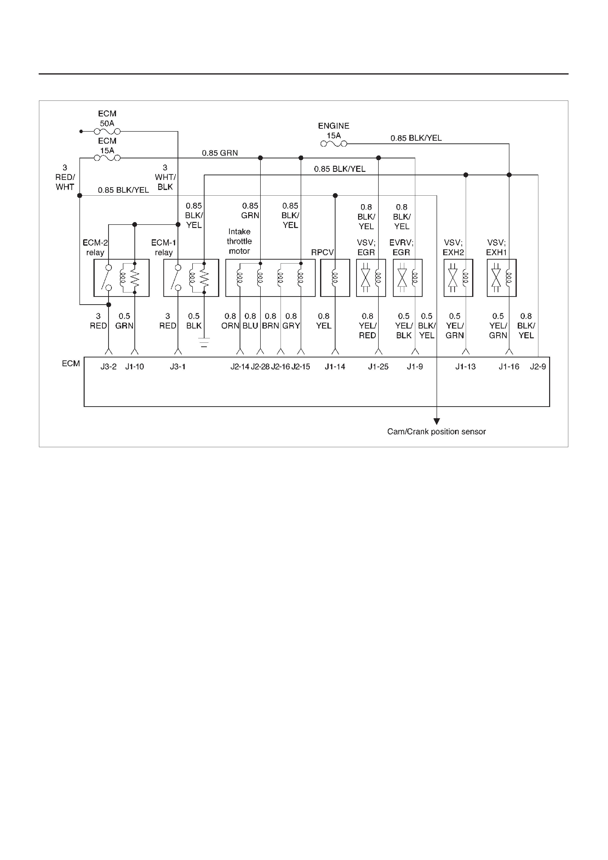
Exhaust Gas Recirculation (EGR) System Check
060RW135
Circuit Description
Introducing exhaust gas into the combustion chamber
lowers combustion temperatures and reduces the
formation of oxides of nitrogen (NOx) in the exhaust gas.
Lower combustion temperatures also prevent detonation.
Diagnostic Aids
The EGR valve chart is a check of the EGR system. An
EGR pintle constantly in the closed position could cause
detonation and high emissions of NOx. An EGR pintle
constantly in the open position would cause a rough idle.

System Check
Step Action Value(s) Yes No
1Move the valve up and down to check the slide
resistance.
Is the slide resistance large? —Go to
Step 8
Go to
Step 2
21. Set the transmission at “Park” or “Neutral”.
2. Put the engine in warming-up operation by idling.
(The engine temperature should be 80°C or more)
3. Disconnect the vacuum hose from the EGR valve.
4. Apply a vacuum of 250 mmHg to the EGR valve by
the vacuum pump (mighty pack).
Does the vibration due to engine operation become
larger? — Go to
Step 3
Go to
Step 9
31. Check if there is not any damage on the vacuum
hose from the vacuum pump to the EGR valve.
2. Install the vacuum pump (mighty pack) to the EGR
valve.
Does the vacuum became 250 mmHg or more at that
time? 250 mmHg or
more Go to
Step 4
Go to
Step 8
4Install the EGR valve and the vacuum hose formally
and increase the engine revolution speed to 3000 rpm.
Can both EGR valve 1 and EGR valve 2 be opened and
closed? —The system is
normal Go to
Step 5
5Measure the resistance of the VSV: EGR coil.
Is the resistance value in the range of 30 W to 50 W?30 ∼ 50 WGo to
Step 6
Go to
Step 10
6Measure the resistance of the EVRV: EGR coil.
Is the resistance value in the range of 10 W to 13 W?10 ∼ 13 WGo to
Step 7
Go to
Step 11
7Was the harness open or poor connection? —Go to
Step 12
Go to
Step 13
8Replace the EGR valve ASM.
Is the action complete? — Verify repair —
9Clean or replace the EGR valve ASM.
Is the action complete? — Verify repair —
10 Replace the EGR VSV.
Is the action complete? — Verify repair —
11 Replace the EGR EVSV.
Is the action complete? — Verify repair —
12 Repair the harness.
Is the action complete? — Verify repair —
13 Replace the ECM (Refer to the Data Programming in
Case of ECM change).
Is the action complete? — Verify repair —

ECM Diagnostic Trouble Codes
The following table lists the diagnostic trouble codes
supported a Tech 2 and to flash.If any DTCs not listed
here are displayed by a Tech 2, the Tech 2 data may be
faulty; notify the Tech 2 manufacturer of any DTCs
displayed that are not included in the following table.
ECM Diagnostic Trouble Codes
DTC
using a
Tech 2
Flash DTC Description MIL
P0107 34 MAP Sensor Low Voltage ON
P0108 34 MAP Sensor High Voltage ON
P0112 23 Intake Air temp Sensor Low Voltage ON
P0113 23 Intake Air temp Sensor High Voltage ON
P0117 14 Engine Coolant Temp Sensor Low Voltage ON
P0118 14 Engine Coolant Temp Sensor High Voltage ON
P0121 33 Accel Position Sensor Rationality ON
P0122 21 Accel Position Sensor Low Voltage ON
P0123 21 Accel Position Sensor High Voltage ON
P0182 15 Fuel Temp Sensor Low Voltage ON
P0183 15 Fuel Temp Sensor High Voltage ON
P0192 63 Rail Pressure Sensor Low Voltage ON
P0193 63 Rail Pressure Sensor High Voltage ON
P1193 64 RPCV Circuit Open/Short —
P1194 61 Rail Pressure System Low Voltage ON
P1195 61 Rail Pressure System High Voltage ON
P1196 62 Rail Pressure System High Warning ON
P0197 16 Oil Temp sensor Low Voltage ON
P0198 16 Oil Temp sensor High Voltage ON
P0201 51 Injector #1 Circuit Fault ON
P0202 52 Injector #2 Circuit Fault ON
P0203 53 Injector #3 Circuit Fault ON
P0204 54 Injector #4 Circuit Fault ON
P0217 22 High Coolant Temp Warning ON
P1217 36 High Oil Temp Warning ON
P0219 11 Engine Over Speed Warning ON
P0336 43 Crank Position Sensor Out of Syncro ON
P0337 43 Crank Position Sensor No Signal ON
P0341 41 Cam Position Sensor Out of Syncro ON
P0342 41 Cam Position Sensor No Signal ON
P0380 66 Glow Relay Circuit Open/Short —
P0381 67 Glow Lamp Circuit Open/Short —
P1403 32 EGR EVRV Fault —
P1404 31 EGR VSV Circuit —
P0405 26 EGR Pressure Sensor Low Voltage ON
P1405 37 EGR EVR V Circuit Open/Short —
P0406 26 EGR Pressure Sensor High Voltage ON

DTC
using a
Tech 2
Flash DTC Description MIL
P0475 71 EXH #1 VSV Circuit Open/Short —
P1475 71 EXH #2 VSV Circuit Open/Short —
P1485 74 Intake Throttle Position Sensor Low Voltage ON
P1486 74 Intake Throttle Position Sensor High Voltage ON
P1487 73 Intake Throttle System Circuit Open/Short ON
P1488 72 Intake Throttle Motor Control Circuit Signal Gap —
P0502 24 Vehicle Speed Sensor No Signal ON
P0510 75 Idle SW Malfunction, Open Circuit ON
P1510 75 Idle SW Malfunction, Short Circuit ON
P0562 35 System Voltage Too Low ON
P1562 35 System Voltage Too Low at Cranking ON
P1587 25 Brake SW Malfunction [B] —
P1588 25 Brake SW Malfunction [A] ON
P0601 55 ECM Checksum Error ON
P1626 56 Immobilizer No Signal ON
P1631 56 Immobilizer Wrong Signal ON
P1648 56 No Security Code Entered ON
P1649 56 Immobilizer Function not Programmed ON
P0650 77 Check Engine Lamp Circuit Open/Short —
P0654 27 Techometer Circuit Open/Short —
P1655 17 Thermo Relay Circuit Open/Short —
P1657 76 ECM Main Relay Circuit Open/Short —
P1589 47 TransMission SW Circuit Open/Short —
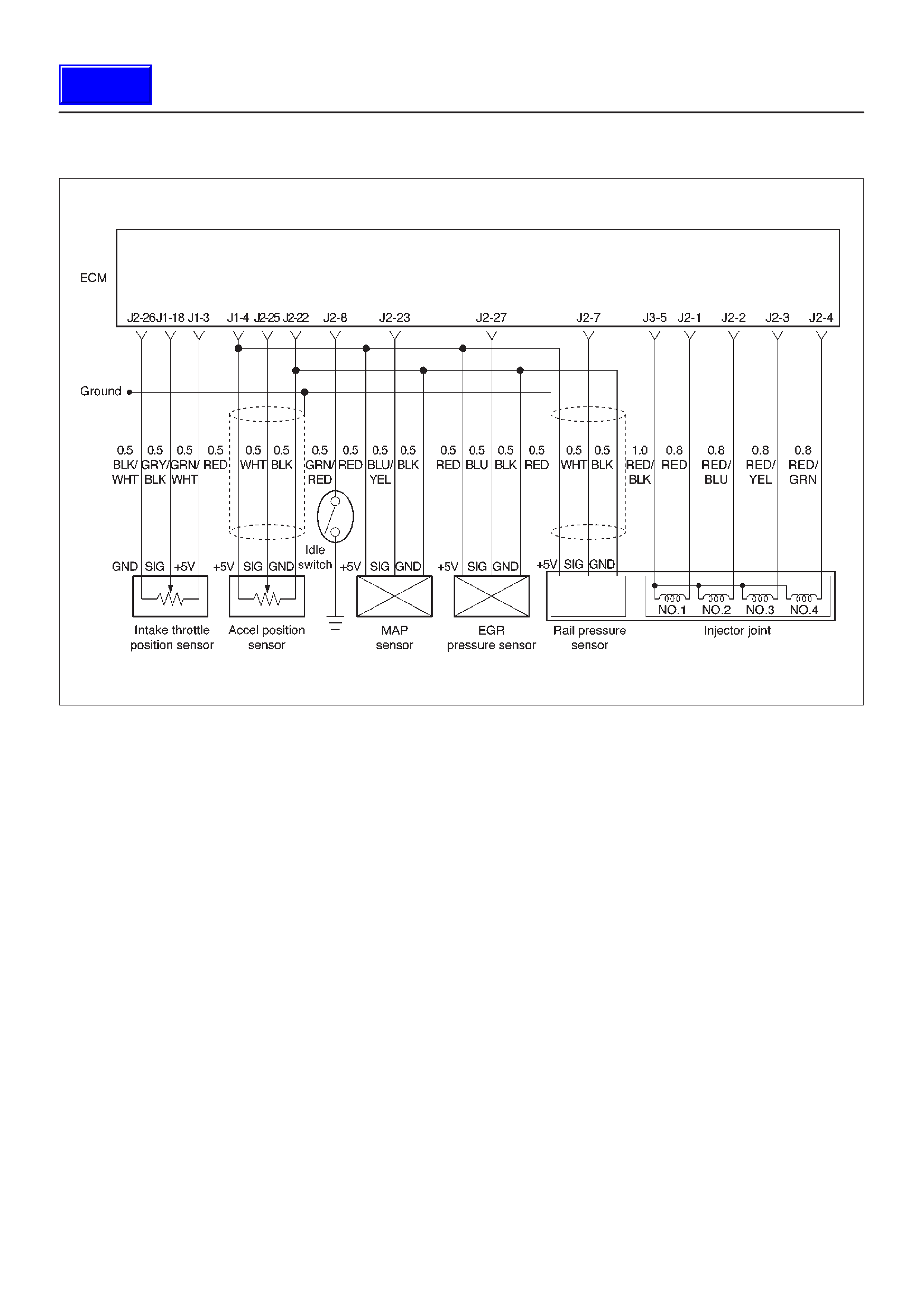
Diagnostic Trouble Code (DTC) P0107 (Flash DTC 34)
MAP Sensor Circuit Low Voltage
060RW134
Circuit Description
The manifold absolute pressure (MAP) sensor responds
to changes in intake manifold pressure (vacuum).
The ECM monitors the MAP signals for voltages outside
the normal range of the MAP sensor. If the ECM detects a
MAP signal voltage that is excessively low, DTC P0107
will be set.
Action Taken When the DTC Sets
DThe ECM will illuminate the malfunction indicator lamp
(MIL) the first time the fault is detected.
DThe ECM will store conditions which were present
when the DTC was set as Freeze Frame and in the
Failure Records data.
Conditions for Clearing the MIL/DTC
DDTC P0107 can be cleared by using the Tech 2 “Clear
Info” function or by disconnecting the ECM battery
feed.
Diagnostic Aids
Check for the following conditions:
DT urn on the ignition switch and stop the engine. At this
time, the boost pressure will be equal to the
atmospheric pressure and the signal voltage will
increase.
DCheck for intermittent codes.
DThe MAP sensor shares a ground with the ECT sensor,
and the Transmission Fluid Temperature sensor.
DPoor connection at ECM – Inspect harness connectors
for backed-out terminals, improper mating, broken
locks, improperly formed or damaged terminals, and
poor terminal-to-wire connection.
DDamaged harness – Inspect the wiring harness for
damage. If the harness appears to be OK, observe the
MAP display on the Tech 2 while moving connectors
and wiring harnesses related to the sensor . A change
in the display will indicate the location of the fault.
If DTC P0107 cannot be duplicated, the information
included in the Failure Records data can be useful in
determining vehicle mileage since the DTC was last set.
If it is determined that the DTC occurs intermittently,
performing the DTC P0107 Diagnostic Chart may isolate
the cause of the fault.
Techline

DTC P0107 – MAP Sensor Circuit Low Voltage
Step Action Value(s) YesNo
1Was the “On-Board Diagnostic (OBD) System Check”
performed? —Go to
Step 2
Go to
OBD
System
Check
2Put the engine into an idling status.
Is the MAP voltage value displayed on the T ech 2 below
the specified value? 0.25 V Go to
Step 3
Refer to
Diagnostic
Aids
and
Symptom
Diagnosis
31. Turn off the ignition switch.
2. Remove the sensor connector connection.
3. Jumper between harness pins “red” and “blue”
wires.
4. Turn on the ignition switch “ON”.
Is the MAP voltage reading above the specified value? 4 V Go to
Step 5
Go to
Step 4
41. Turn off the ignition switch.
2. Remove the jumper wire.
3. Connect the relay & solenoid checker
(5-8840-0386-0) to the battery voltage, then check
the MAP signal circuit (blue wire).
4. Turn on the ignition switch.
Is the value displayed on the T ech 2 above the specified
value? 4 V Go to
Step 6
Go to
Step 7
5Check the terminal connection at the MAP sensor and
repair or replace terminal if necessary.
Is the action complete? — Verify repair —
6Repair the 5V power circuit (red) harness or Replace
the ECM (Refer to the Data Programming in Case of
ECM change).
Is the action complete? — Verify repair —
7Repair the signal circuit (blue) harness or Replace the
ECM (Refer to the Data Programming in Case of ECM
change).
Is the action complete? — Verify repair —

Diagnostic Trouble Code (DTC) P0108 (Flash DTC 34)
MAP Sensor Circuit High Voltage
060RW134
Circuit Description
The manifold absolute pressure (MAP) sensor responds
to changes in intake manifold pressure (vacuum).
The ECM monitors the MAP signals for voltages outside
the normal range of the MAP sensor. If the ECM detects a
MAP signal voltage that is excessively high, DTC P0108
will be set.
Action Taken When the DTC Sets
DThe ECM will illuminate the malfunction indicator lamp
(MIL) the first time the fault is detected.
DThe ECM will store conditions which were present
when the DTC was set as Freeze Frame and in the
Failure Records data.
Conditions for Clearing the MIL/DTC
DDTC P0108 can be cleared by using the Tech 2 “Clear
Info” function or by disconnecting the ECM battery
feed.
Diagnostic Aids
Check for the following conditions:
DT urn on the ignition switch and stop the engine. At this
time, the boost pressure will be equal to the
atmospheric pressure and the signal voltage will
increase.
DPoor connection at ECM – Inspect harness connectors
for backed-out terminals, improper mating, broken
locks, improperly formed or damaged terminals, and
poor terminal-to-wire connection.
DDamaged harness – Inspect the wiring harness for
damage. If the harness appears to be OK, observe the
MAP display on the Tech 2 while moving connectors
and wiring harnesses related to the sensor . A change
in the display will indicate the location of the fault.
If DTC P0108 cannot be duplicated, the information
included in the Failure Records data can be useful in
determining vehicle mileage since the DTC was last set. If
it is determined that the DTC occurs intermittently.

Sensor Circuit High Voltage
Step Action Value(s) YesNo
1Was the “On-Board Diagnostic (OBD) System Check”
performed? —Go to
Step 2
Go to
OBD
System
Check
2Put the engine into an idling status.
Is the MAP voltage value displayed on the Tech 2
above the specified value? 4 V Go to
Step 3
Go to
Step 4
31. Turn off the ignition switch.
2. Remove the sensor connector connection.
3. Turn on the ignition switch “ON”.
Is the MAP voltage value displayed on the T ech 2 below
the specified value? 1 V Go to
Step 5
Go to
Step 6
4Is the MAP voltage value displayed on the T ech 2 below
the specified value?
1 V Refer to
Chart P0107
Refer to
Diagnostic
Aids
and
Symptom
Diagnosis
5Connect the relay and solenoid checker
(5-8840-0386-0) to the battery voltage, then check the
sensor grounding circuit.
Does the checker lamp come on? —Go to
Step 7
Go to
Step 8
6A voltage short circuit occurs in the MAP signal circuit
or this circuit is shorted with the 5V power circuit.
Repair the harness or Replace the ECM (Refer to the
Data Programming in Case of ECM change).
Is the action complete? — Verify repair —
7Replace the MAP sensor hose or the MAP sensor.
Is the action complete? — Verify repair —
8Repair the harness for open ground circuit.
Is the action complete? — Verify repair —

Diagnostic Trouble Code (DTC) P0112 (Flash DTC 23)
IAT Sensor Circuit Low Voltage
060RW129
Circuit Description
The Intake air temperature (IAT) sensor is a thermistor
which measures the temperature of the air entering the
engine. The Engine Control Module ECM applies 5 volts
through a pull-up resistor to the IAT sensor. When the
intake air is cold, the sensor resistance is high and the
ECM will monitor a high signal voltage on the IAT signal
circuit. If the intake air is warm, the sensor resistance is
lower , causing the ECM to monitor a lower voltage. DTC
P0112 will set when the ECM detects an excessively low
signal voltage on the Intake air temperature sensor signal
circuit.
Action Taken When the DTC Sets
DThe ECM will illuminate the malfunction indicator lamp
(MIL) the first time the fault is detected.
DThe ECM will store conditions which were present
when the DTC was set as Freeze Frame and in the
Failure Records data.
Conditions for Clearing the MIL/DTC
DDTC P0112 can be cleared by using the Tech 2 “Clear
Info” function or by disconnecting the ECM battery
feed.
Diagnostic Aids
Check for the following conditions:
DPoor connection at ECM – Inspect harness connectors
for backed-out terminals, improper mating, broken
locks, improperly formed or damaged terminals, and
poor terminal-to-wire connection.
DDamaged harness – Inspect the wiring harness for
damage. If the harness appears to be OK, observe the
IA T display on the T ech 2 while moving connectors and
wiring harnesses related to the IAT sensor. A change
in the IAT display will indicate the location of the fault.
If DTC P0112 cannot be duplicated, the information
included in the Failure Records data can be useful in
determining vehicle mileage since the DTC was last set.

Test Description
Number(s) below refer to the step number(s) on the
Diagnostic Chart:
2. Verifies that the fault is present.
3. If DTC P0112 can be repeated only by duplicating
the Failure Records condition, refer to the
Temperature vs. Resistance Value
table. The table
may be used to test the IAT sensor at various
temperatures to evaluate the possibility of a
“shifted” sensor that may be stored above or below
a certain temperature. If this is the case, replace
the IAT sensor. If the IAT sensor appears to be OK,
the fault is intermittent; refer to
Diagnostic Aids
.
Intake Air Temperature Sensor
°C°F Ohms
Temperature vs. Resistance Values
(approximate)
25 77 2796
15 59 4450
5 41 7280
DTC P0112 – IAT Sensor Low Voltage
Step Action Value(s) YesNo
1Was the “On-Board Diagnostic (OBD) System Check”
performed? —Go to
Step 2
Go to
OBD
System
Check
21. Ignition “ON,” engine “OFF.”
2. Using a Tech 2, monitor the intake air temperature
(IAT).
Is the intake air temperature greater than the specified
value? 148°C
(283°F) Go to
Step 4
Go to
Step 3
31. Ignition “ON,” engine “OFF.” Review and record
Tech 2 Failure Records data.
2. Operate the vehicle within Failure Records
conditions as noted.
3. Using a Tech 2, monitor the “ DTC” info for DTC
P0112.
Does the Tech 2 indicate DTC P0112 failed this
ignition? —Refer to
Test
Description
Refer to
Diagnostic
Aids
41. Ignition “OFF.”
2. Disconnect the IAT sensor electrical connector.
3. Ignition “ON.”
4. Observe the manifold air temperature on the T ech 2.
Is the manifold air temperature below the specified
value? –38°C
(–36°F) Go to
Step 6
Go to
Step 5
51. Ignition “OFF.”
2. Disconnect the ECM electrical connectors.
3. Check the IAT sensor signal circuit for a short to
ground.
Is the IAT sensor signal circuit shorted to ground? — Verify repair Go to
Step 7
6Replace the IAT sensor.
Is the action complete? — Verify repair —
7Replace the ECM (Refer to the Data Programming in
Case of ECM change).
Is the action complete? — Verify repair —

Diagnostic Trouble Code (DTC) P0113 (Flash DTC 23)
IAT Sensor Circuit High Voltage
060RW129
Circuit Description
The intake air temperature (IAT) sensor is a thermistor
which measures the temperature of the air entering the
engine. The Engine Control Module ECM applies 5 volts
through a pull-up resistor to the IAT sensor. When the
intake air is cold, the sensor resistance is high and the
ECM will monitor a high signal voltage on the IAT signal
circuit. If the intake air is warm, the sensor resistance is
lower causing the ECM to monitor a lower voltage. DTC
P01 13 will set when the ECM detects an excessively high
signal voltage on the intake air temperature sensor signal
circuit.
Action Taken When the DTC Sets
DThe ECM will illuminate the malfunction indicator lamp
(MIL) the first time the fault is detected.
DThe ECM will store conditions which were present
when the DTC was set as Freeze Frame and in the
Failure Records data.
Conditions for Clearing the MIL/DTC
DDTC P0113 can be cleared by using the Tech 2 “Clear
Info” function or by disconnecting the ECM battery
feed.
Diagnostic Aids
Check for the following conditions:
DPoor connection at ECM – Inspect harness connectors
for backed-out terminals, improper mating, broken
locks, improperly formed or damaged terminals, and
poor terminal-to-wire connection.
DDamaged harness – Inspect the wiring harness for
damage. If the harness appears to be OK, observe the
IA T display on the T ech 2 while moving connectors and
wiring harnesses related to the IAT sensor. A change
in the IAT display will indicate the location of the fault.
If DTC P0113 cannot be duplicated, the information
included in the Failure Records data can be useful in
determining vehicle mileage since the DTC was last set.

Test Description
Number(s) below refer to the step number(s) on the
Diagnostic Chart:
2. Verifies that the fault is present.
3. If DTC P0113 can be repeated only by duplicating
the Failure Records conditions, refer to the
“Temperature vs. Resistance Values” table. The
table may be used to test the MAT sensor at various
temperatures to evaluate the possibility of a
“shifted” sensor that may be open above or below a
certain temperature. If this is the case, replace the
MAT sensor. If the MAT sensor appears to be OK,
the fault is intermittent; refer to
Diagnostic Aids
.
Manifold Air Temperature Sensor
°C°F Ohms
Temperature vs. Resistance Values
(approximate)
25 77 2796
15 59 4450
5 41 7280
DTC P0113 –IAT Sensor Circuit High Voltage
Step Action Value(s) YesNo
1Was the “On-Board Diagnostic (OBD) System Check”
performed? —Go to
Step 2
Go to
OBD
System
Check
2Ignition “ON,” engine “OFF.” Observe the “Intake Air
Temp” display on the Tech 2.
Is the “Intake Air Temp” below the specified value? –38°C
(–36°F) Go to
Step 4
Go to
Step 3
31. Ignition “ON,” engine “OFF.”
2. Review and record Tech 2 Failure Records data
parameters.
3. Operate the vehicle within Failure Records
conditions as noted.
4. Using a Tech 2, monitor “ DTC” info for DTC P01 13.
Does the Tech 2 indicate DTC P0113 failed? —Refer to
Test
Description
Refer to
Diagnostic
Aids
41. Ignition “OFF.”
2. Disconnect the IAT sensor electrical connector.
3. Jumper the IA T signal circuit and the sensor ground
circuit together at the IAT sensor harness
connector.
4. Ignition “ON.”
5. Observe the “Intake Air Temp” display on the Tech
2.
Is the “Intake Air Temp” at the specified value? 140°C
(284°F) Go to
Step 6
Go to
Step 5
51. Jumper the IAT signal circuit at the IAT sensor
harness connector to chassis ground.
2. Observe the “Intake Air Temp” display on the Tech
2.
Is the “Intake Air Temp” at the specified value? 140°C
(284°F) Go to
Step 7
Go to
Step 8
6Check for poor connections at the IAT sensor and
replace terminals if necessary.
Did any terminals require replacement? — Verify repair Go to
Step 10
71. Ignition “OFF.”
2. Disconnect the ECM, and check the IAT sensor
ground circuit for an open.
3. If the IAT sensor ground circuit is open, repair it as
necessary.
Was the IAT sensor ground circuit open? — Verify repair Go to
Step 9

DTC P0113 –IAT Sensor Circuit High Voltage (Cont'd)
Step NoYesValue(s)Action
81. Ignition “OFF.”
2. Disconnect the ECM, and check the IAT signal
circuit for an open.
3. If the IAT sensor signal circuit is open, repair it as
necessary.
Was the IAT signal circuit open? — Verify repair Go to
Step 9
9Check for a poor sensor ground or IAT signal circuit
terminal connection at the ECM and replace
terminal(s) if necessary.
Did any of the terminals need to be replaced? — Verify repair Go to
Step 11
10 Replace the IAT sensor.
Is the action complete? — Verify repair —
11 Replace the ECM (Refer to the Data Programming in
Case of ECM change).
Is the action complete? — Verify repair —

Diagnostic Trouble Code (DTC) P0117 (Flash DTC 14)
ECT Sensor Low Voltage
060RW129
Circuit Description
The engine coolant temperature (ECT) sensor is a
thermistor mounted on a coolant crossover pipe at the
rear of the engine. The Engine Control Module ECM
applies a voltage (about 5 volts) through a pull-up resistor
to the ECT signal circuit. When the engine coolant is cold,
the sensor (thermistor) resistance is high, therefore the
ECM will measure a high signal voltage. As the engine
coolant warms, the sensor resistance becomes lower,
and the ECT signal voltage measured at the ECM drops.
Action Taken When the DTC Sets
DThe ECM will store conditions which were present
when the DTC was set as Freeze Frame and in the
Failure Records data.
Conditions for Clearing the MIL/DTC
DDTC P0117 can be cleared by using the Tech 2 “Clear
Info” function or by disconnecting the ECM battery
feed.
Diagnostic Aids
Check for the following conditions:
DPoor connection at ECM – Inspect harness connectors
for backed-out terminals, improper mating, broken
locks, improperly formed or damaged terminals, and
poor terminal-to-wire connection.
DDamaged harness – Inspect the wiring harness for
damage. If the harness appears to be OK, observe the
ECT display on the Tech 2 while moving connectors
and wiring harnesses related to the ECT sensor. A
change in the ECT display will indicate the location of
the fault.
If DTC P0117 cannot be duplicated, the information
included in the Failure Records data can be useful in
determining vehicle mileage since the DTC was last set.
If it is determined that the DTC occurs intermittently.
Test Description
Number(s) below refer to the step number(s) on the
Diagnostic Chart.
2. Verifies that the fault is present.
3. If DTC P0117 can be repeated only by duplicating
the Failure Records conditions, refer to the
“Temperature vs. Resistance Values” table. The
table may be used to test the ECT sensor at various
temperatures to evaluate the possibility of a
“shifted” sensor that may be shorted above or below
a certain temperature. If this is the case, replace
the ECT sensor. If the ECT sensor appears to be
OK, the fault is intermittent; refer to
Diagnostic Aids
.

Engine Coolant Temperature Sensor
°C°F Ohms
Temperature vs. Resistance Values
(approximate)
25 77 2796
15 59 4450
DTC P0117 – ECT Sensor Low Voltage
Step Action Value(s) YesNo
1Was the “On-Board Diagnostic (OBD) System Check”
performed? —Go to
Step 2
Go to
OBD
System
Check
21. Ignition “ON,” engine “OFF.”
2. Observe the “Eng Cool T emp” display on the T ech 2.
Is the “Eng Cool Temp” below the specified value? 139°C
(282°F) Go to
Step 4
Go to
Step 3
31. Ignition “ON,” engine “OFF.”
2. Review and record Tech 2 Failure Records data.
3. Operate the vehicle within Failure Records
conditions as noted.
4. Using a Tech 2, monitor “ DTC” info for DTC P01 17.
Does the Tech 2 indicate DTC P0117 failed this
ignition? — Go to
Step 4
Refer to
Diagnostic
Aids
41. Disconnect the ECT sensor electrical connector.
2. Observe the “Eng Cool T emp” display on the T ech 2.
Is the “Eng Cool Temp” at the specified value? –39°C
(–38°F) Go to
Step 6
Go to
Step 5
51. Ignition “OFF.”
2. Disconnect the ECM and check the ECT signal
circuit for a short to ground or a short to the sensor
ground circuit.
3. If the ECT signal circuit is shorted. repair it as
necessary.
Was the ECT signal circuit shorted to ground? — Verify repair Go to
Step 7
6Replace the ECT sensor.
Is the action complete? — Verify repair —
7Replace the ECM (Refer to the Data Programming in
Case of ECM change).
Is the action complete? — Verify repair —

Diagnostic Trouble Code (DTC) P0118 (Flash DTC 14)
ECT Sensor High Voltage
060RW129
Circuit Description
The engine coolant temperature (ECT) sensor is a
thermistor mounted in on a coolant crossover pipe at the
rear of the engine. The Engine Control Module ECM
applies a voltage (about 5 volts) through a pull-up resistor
to the ECT signal circuit. When the engine coolant is cold,
the sensor (thermistor) resistance is high, therefore the
ECM will measure a high signal voltage. As the engine
coolant warms, the sensor resistance becomes less, and
the ECT signal voltage measured at the ECM drops.
Action Taken When the DTC Sets
DThe ECM will store conditions which were present
when the DTC was set as Freeze Frame and in the
Failure Records data.
Conditions for Clearing the MIL/DTC
DDTC P0118 can be cleared by using the Tech 2 “Clear
Info” function or by disconnecting the ECM battery
feed.
Diagnostic Aids
Check for the following conditions:
DPoor connection at ECM – Inspect harness connectors
for backed-out terminals, improper mating, broken
locks, improperly formed or damaged terminals, and
poor terminal-to-wire connection.
DDamaged harness – Inspect the wiring harness for
damage. If the harness appears to be OK, observe the
ECT display on the Tech 2 while moving connectors
and wiring harnesses related to the ECT sensor. A
change in the ECT display will indicate the location of
the fault.
If DTC P0118 cannot be duplicated, the information
included in the Failure Records data can be useful in
determining vehicle mileage since the DTC was last set.

Test Description
Number(s) below refer to the step number(s) on the
Diagnostic Chart.
2. Verifies that the fault is present.
3. If DTC P0118 can be repeated only by duplicating
the Failure Records conditions, refer to the
“Temperature vs. Resistance Value” table. The
table may be used to test the ECT sensor at various
temperatures to evaluate the possibility of a
“shifted” sensor that may be shorted above or below
a certain temperature. If this is the case, replace
the ECT sensor. If the ECT sensor appears to be
OK, the fault is intermittent; refer to
Diagnostic Aids
.
Engine Coolant Temperature Sensor
°C°F Ohms
Temperature vs. Resistance Values
(approximate)
80 176 332
25 77 2796
15 59 4450
DTC P0118 – ECT Sensor High Voltage
Step Action Value(s) YesNo
1Was the “On-Board Diagnostic (OBD) System Check”
performed? —Go to
Step 2
Go to
OBD
System
Check
21. Ignition “ON,” engine “OFF.”
2. Observe the “Eng Cool T emp” display on the T ech 2.
Is the “Eng Cool Temp” below the specified value? –39°C
(–38°F) Go to
Step 4
Go to
Step 3
31. Ignition “ON,” engine “OFF.”
2. Review and record Tech 2 Failure Records data.
3. Operate the vehicle within Failure Records
conditions as noted.
4. Using a Tech 2, monitor the “ DTC” info for DTC
P0118.
Does the Tech 2 indicate DTC P0118 failed? —Refer to
Test
Description
Refer to
Diagnostic
Aids
41. Disconnect the ECT sensor electrical connector.
2. Jumper the ECT signal circuit and the sensor
ground circuit together at the ECT sensor harness
connector.
3. Observe the “Eng Cool T emp” display on the T ech 2.
Is the “Eng Cool Temp” at the specified value? 140°C
(284°F) Go to
Step 6
Go to
Step 5
51. Jumper the ECT signal circuit at the ECT sensor
harness connector to chassis ground.
2. Observe the “Eng Cool T emp” display on the T ech 2.
Is the “Eng Cool Temp” at the specified value? 140°C
(284°F) Go to
Step 7
Go to
Step 8
6Check for poor connections at the ECT sensor and
replace terminals if necessary.
Did any terminals require replacement? — Verify repair Go to
Step 10
71. Ignition “OFF.”
2. Disconnect the ECM, and check the ECT sensor
ground circuit for an open.
3. If the ECT sensor ground circuit is open, repair it as
necessary.
Was the ECT sensor ground circuit open? — Verify repair Go to
Step 9

DTC P0118 – ECT Sensor High Voltage (Cont'd)
Step NoYesValue(s)Action
81. Ignition “OFF.”
2. Disconnect the ECM, and check the ECT signal
circuit for an open.
3. If the ECT sensor signal circuit is open, repair it as
necessary.
Was the ECT signal circuit open? — Verify repair Go to
Step 9
9Check for a poor sensor ground or ECT signal circuit
terminal connection at the ECM and replace
terminal(s) if necessary.
Did any of the terminals need to be replaced? — Verify repair Go to
Step 11
10 Replace the ECT sensor.
Is the action complete? — Verify repair —
11 Replace the ECM (Refer to the Data Programming in
Case of ECM change).
Is the action complete? — Verify repair —

Diagnostic Trouble Code (DTC) P0121 (Flash DTC 33)
AP Sensor Rationality
060RW134
Circuit Description
The accel position (AP) sensor circuit provides a voltage
signal that changes relative to throttle blade angle.
The AP signal is one of the most important inputs used by
the Engine Control Module ECM for fuel volume control
and many of the ECM-controlled outputs. If the ECM
detects an out-of-range condition, DTC P0121 will set.
Action Taken When the DTC Sets
DThe ECM will illuminate the malfunction indicator lamp
(MIL) after fault is detected.
DThe ECM will store conditions which were present
when the DTC was set as Freeze Frame and in the
Failure Records data.
Conditions for Clearing the MIL/DTC
DDTC P0121 can be cleared by using the Tech 2 “Clear
info ” function or by disconnecting the ECM battery
feed.
Diagnostic Aids
Check for the following conditions:
DPoor connection at ECM – Inspect harness connectors
for backed-out terminals, improper mating, broken
locks improperly formed or damaged terminals, and
poor terminal-to-wire connection.
DDamaged harness – Inspect the wiring harness for
damage. If the harness appears to be OK, observe the
ECT display on the Tech 2 while moving connectors
and wiring harnesses related to the sensor . A change
in the display will indicate the location of the fault.
If DTC P0121 cannot be duplicated, the information
included in the Failure Records data can be useful in
determining vehicle mileage since the DTC was last set.

DTC P0121 –AP Sensor Rationality
Step Action Value(s) YesNo
1Was the “On-Board Diagnostic (OBD) System Check”
performed? —Go to
Step 2
Go to
OBD
System
Check
2Check the Idle SW.
Was the Idle SW circuit open or darmage? —
Replace the
Idle SW
circuit Go to
Step 3
3Observe the AP angle reading on the Tech 2 while
slowly opening the throttle.
Does the AP angle increase steadily and evenly from
the closed throttle value to the wide open throttle
value?
Closed
throttle = 0%
Wide open
throttle =
100%
Refer to
Diagnostic
Aids
Go to
Step 4
41. Disconnect the AP sensor.
2. Observe the AP sensor reading on the Tech 2.
Is the AP sensor reading near the specified value? 0 V Go to
Step 5
Go to
Step 6
51. Connect a test light between the 5 volt reference
“J2” circuit and the AP sensor signal circuit at the AP
sensor harness connector.
2. Observe the AP sensor reading on the Tech 2.
Is the AP sensor reading at the specified value? 5 V Go to
Step 8
Go to
Step 7
6Check the following items:
1. AP signal circuit for a short to voltage.
2. AP sensor ground circuit for high resistance
between the ECM and the AP sensor.
3. AP sensor ground circuit for a poor connection.
4. If a problem is found, repair wiring harness as
necessary.
Was a problem found? — Verify repair Go to
Step 9
7Check the following items:
1. AP signal circuit or 5 volt reference “J2” circuit for a
poor connection.
2. AP signal circuit or 5 volt reference “J2” circuit for
high resistance between the ECM and the AP
sensor.
3. If a problem is found, repair wiring harness as
necessary.
Was a problem found? — Verify repair Go to
Step 9
8Replace the AP sensor.
Is the action complete? — Verify repair —
9Replace the ECM (Refer to the Data Programming in
Case of ECM change).
Is the action complete? — Verify repair —
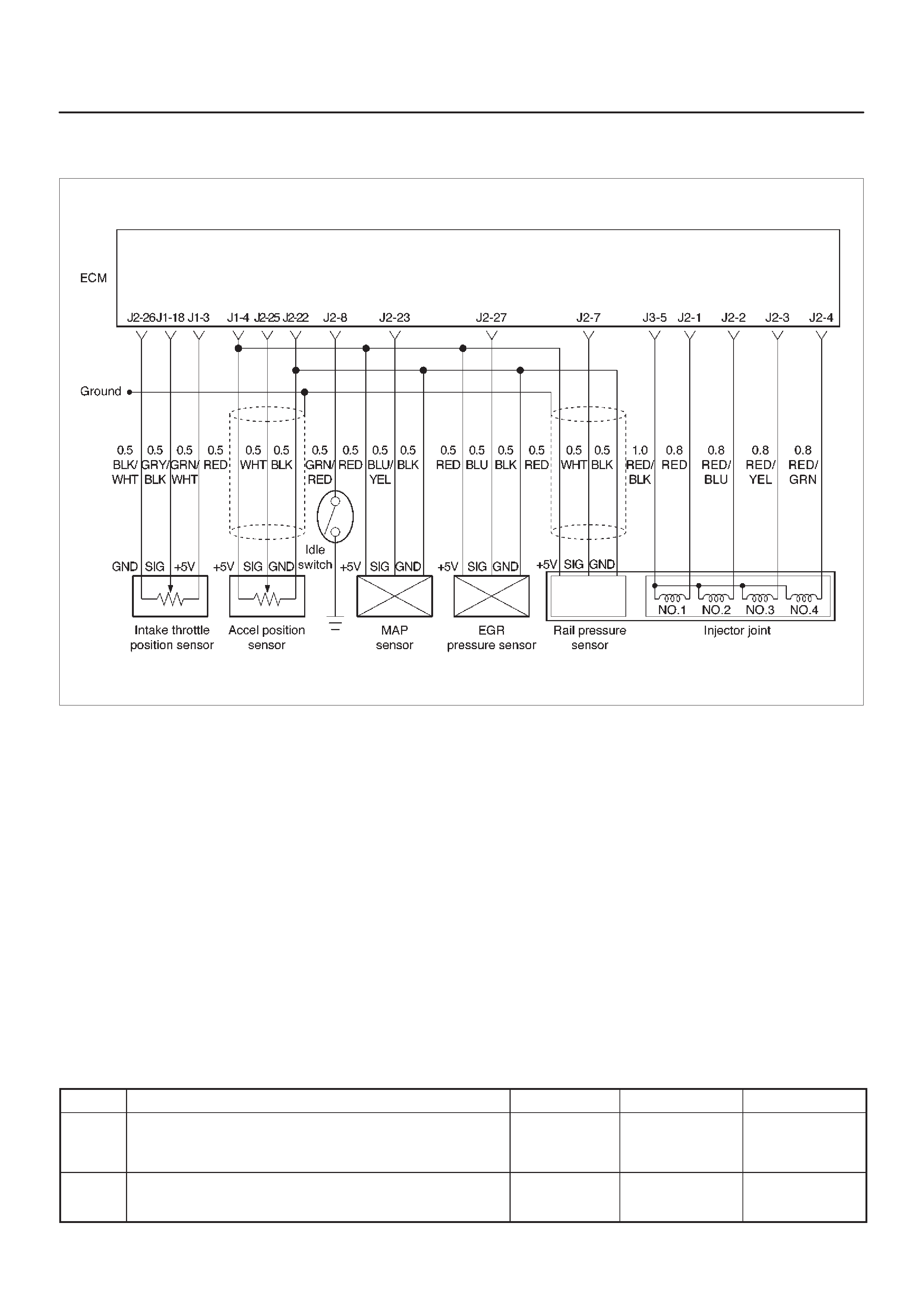
Diagnostic Trouble Code (DTC) P0122 (Flash DTC 21)
AP Sensor Low Voltage
060RW134
Circuit Description
The accelerator position (AP) sensor circuit provides a
voltage signal that changes relative to throttle blade
angle.
The AP signal is used by the Engine Control Module ECM
for fuel volume control and many of the ECM-controlled
outputs.
Action Taken When the DTC Sets
DThe ECM will store conditions which were present
when the DTC was set as Freeze Frame and in the
Failure Records data.
Conditions for Clearing the MIL/DTC
DDTC P0122 can be cleared by using the Tech 2 “Clear
Info” function or by disconnecting the ECM battery
feed.
Diagnostic Aids
Check for the following conditions:
DPoor connection at ECM – Inspect harness connectors
for backed-out terminals, improper mating, broken
locks, improperly formed or damaged terminals, and
poor terminal-to-wire connection.
DDamaged harness – Inspect the wiring harness for
damage. If the harness appears to be OK, observe the
throttle position display on the Tech 2 while moving
connectors and wiring harnesses related to the TP
sensor. A change in the display will indicate the
location of the fault.
If DTC P0122 cannot be duplicated, the information
included in the Failure Records data can be useful in
determining vehicle mileage since the DTC was last set.
DTC P0122 –AP Sensor Low Voltage
Step Action Value(s) YesNo
1Was the “On-Board Diagnostic (OBD) System Check”
performed? —Go to
Step 2
Go to
OBD
System
Check
2Check the AP sensor signal circuit.
Was the AP sensor signal circuit open or darmage? —Replace the
APS circuit Go to
Step 3

DTC P0122 –AP Sensor Low Voltage (Cont'd)
Step NoYesValue(s)Action
3 1. Ignition “ON,” engine “OFF.”
2. With the throttle closed, observe the “AP Sensor”
display on the Tech 2.
Is the “AP Sensor” below the specified value? 0.1 V Go to
Step 5
Go to
Step 4
41. Ignition “ON,” engine “OFF.”
2. Review and record Tech 2 Failure Records data.
3. Operate the vehicle within Failure Records
conditions as noted.
4. Using a Tech 2, monitor the “DTC” info for DTC
P0122.
Does the Tech 2 indicate DTC P0122 failed? —Go to
Step 5
Refer to
Diagnostic
Aids
51. Ignition “OFF.”
2. Disconnect the AP sensor electrical connector.
3. Jumper the 5 volt reference “J2” circuit and the AP
signal together at the AP sensor harness connector.
4. Ignition “ON.”
Observe the “AP Sensor” display on the Tech 2.
Is the “AP Sensor” at the specified value? 5 V Go to
Step 11
Go to
Step 6
61. Disconnect jumper.
2. Connect a test light between B+ and the AP sensor
signal circuit at the AP sensor harness connector.
Observe the “AP Sensor” display on the Tech 2.
Is the “AP Sensor” at the specified value? 5 V Go to
Step 7
Go to
Step 9
71. Ignition “OFF.”
2. Disconnect the ECM and check the 5 volt reference
“A” circuit for an open or short to ground.
3. If the 5 volt reference “J2” circuit is open or shorted
to ground, repair it as necessary.
W as the 5 volt reference “J2” circuit open or shorted to
ground? —Verify repair Go to
Step 8
8Check the 5 volt reference “J2” circuit for a poor
connection at the ECM and replace the terminal if
necessary.
Did the terminal require replacement? — Verify repair Go to
Step 13
91. Ignition “OFF.”
2. Disconnect the ECM, and check the AP signal
circuit for an open, short to ground, or short to the
sensor ground circuit.
3. If the AP sensor signal circuit is open or shorted to
ground, repair it as necessary.
Was the AP signal circuit open or shorted to ground? — Verify repair Go to
Step 10
10 Check the AP sensor signal circuit for a poor
connection at the ECM and replace the terminal if
necessary.
Did the terminal require replacement? — Verify repair Go to
Step 13
11 Check the AP sensor signal circuit for a poor
connection at the AP sensor and replace the terminal if
necessary.
Did the terminal require replacement? — Verify repair Go to
Step 12

DTC P0122 –AP Sensor Low Voltage (Cont'd)
Step NoYesValue(s)Action
12 Replace the AP sensor.
Is the action complete? — Verify repair —
13 Replace the ECM (Refer to the Data Programming in
Case of ECM change).
Is the action complete? — Verify repair —

Diagnostic Trouble Code (DTC) P0123 (Flash DTC 21)
AP Sensor High Voltage
060RW134
Circuit Description
The accelerator position (AP) sensor circuit provides a
voltage signal that changes relative to throttle blade
angle.
The TP signal is one of the most important inputs used by
the Engine Control Module ECM for fuel volume control
and many of the ECM-controlled outputs.
Action Taken When the DTC Sets
DThe ECM will store conditions which were present
when the DTC was set as Freeze Frame and in the
Failure Records data.
Conditions for Clearing the MIL/DTC
DDTC P0123 can be cleared by using the Tech 2 “Clear
Info” function or by disconnecting the ECM battery
feed.
Diagnostic Aids
Check for the following conditions:
DPoor connection at ECM – Inspect harness connectors
for backed-out terminals, improper mating, broken
locks, improperly formed or damaged terminals, and
poor terminal-to-wire connection.
DDamaged harness – Inspect the wiring harness for
damage. If the harness appears to be OK, observe the
AP sensor display on the Tech 2 while moving
connectors and wiring harnesses related to the TP
sensor. A change in the display will indicate the
location of the fault.
DFaulty AP sensor – With the ignition key “ON,” engine
“OFF,” observe the AP sensor display on the Tech 2
while slowly depressing the accelerator to wide open
throttle. If a voltage over 4.88 volts is seen at any point
in normal accelerator travel, replace the AP sensor.
If DTC P0123 cannot be duplicated, the information
included in the Failure Records data can be useful in
determining vehicle mileage since the DTC was last set.
Test Description
Number (s) below refer to the step number(s) on the
Diagnostic Chart.
8. Components that share the AP sensor 5 volt reference
“A” circuit include the following device:

DTC P0123 – AP Sensor High Voltage
Step Action Value(s) YesNo
1Was the “On-Board Diagnostic (OBD) System Check”
performed? —Go to
Step 2
Go to
OBD
System
Check
2Check the AP sensor signal circuit.
Was the AP sensor signal circuit open or darmage? —Replace the
APS circuit Go to
Step 3
31. Ignition “ON,” engine “OFF.”
2. With the throttle closed, observe the “AP Sensor”
display on the Tech 2.
Is the “AP Sensor” above the specified value? 4.5 V Go to
Step 5
Go to
Step 4
41. Ignition “ON,” engine “OFF.”
2. Review and record Tech 2 Failure Records data.
3. Operate the vehicle within Failure Records
conditions as noted.
4. Using a Tech 2, monitor “DTC” info for DTC P0123.
Does the Tech 2 indicate DTC P0123 failed. —Go to
Step 5
Refer to
Diagnostic
Aids
51. Disconnect the AP sensor electrical connector.
2. Observe the “AP Sensor” display on the Tech 2.
Is the “AP Sensor” near the specified value? 0 V Go to
Step 6
Go to
Step 7
6Probe the sensor ground circuit at the AP sensor
harness connector with a test light connected to B+.
Is the test light “ON?” —Go to
Step 8
Go to
Step 11
71. Ignition “OFF,” disconnect the ECM.
2. Ignition “ON,” engine “OFF.”
3. Check for a short to voltage on the AP sensor signal
circuit.
4. If the AP sensor signal circuit is shorted, repair it as
necessary.
Was the AP sensor signal circuit shorted? — Verify repair Go to
Step 13
81. Ignition “ON.”
2. Monitor the “AP Sensor” Tech 2 display while
disconnecting each of the components that share
the 5 volt reference “J2” circuit (one at a time).
3. If the “AP Sensor” Tech 2 display changes, replace
the component that caused the display to change
when disconnected.
Does disconnecting any of these components cause
the “AP Sensor” display to change? — Verify repair Go to
Step 9
91. Ignition “OFF,” disconnect the ECM.
2. Ignition “ON,” engine “OFF.”
3. Check for a short to B+ on the 5 volt reference “A”
circuit.
4. If the 5 volt reference “J2” circuit is shorted, repair it
as necessary.
Was the 5 volt reference “J2” circuit shorted? — Verify repair Go to
Step 10
10 Check for poor electrical connections at the AP sensor
and replace terminals if necessary.
Did any terminals require replacement? — Verify repair Go to
Step 12

DTC P0123 – AP Sensor High Voltage (Cont'd)
Step NoYesValue(s)Action
11 1. Ignition “OFF.”
2. Disconnect the ECM, and check for an open sensor
ground circuit to the AP sensor.
3. If a problem is found, repair it as necessary.
W as the sensor ground circuit to the AP sensor open? —Verify repair Go to
Step 13
12 Replace the AP sensor.
Is the action complete? — Verify repair —
13 Replace the ECM (Refer to the Data Programming in
Case of ECM change).
Is the action complete? — Verify repair —

Diagnostic Trouble Code (DTC) P0182 (Flash DTC 15)
FT Sensor Low Voltage
060RW129
Circuit Description
The fuel temperature (FT) sensor is a thermistor mounted
on a coolant crossover pipe at the rear of the engine. The
Engine Control Module ECM applies a voltage (about 5
volts) through a pull-up resistor to the FT signal circuit.
When the fuel is cold, the sensor (thermistor) resistance
is high, therefore the ECM will measure a high signal
voltage. As the fuel warms, the sensor resistance
becomes lower, and the FT signal voltage measured at
the ECM drops.
Action Taken When the DTC Sets
DThe ECM will store conditions which were present
when the DTC was set as Freeze Frame and in the
Failure Records data.
Conditions for Clearing the MIL/DTC
DDTC P0182 can be cleared by using the Tech 2 “Clear
Info” function or by disconnecting the ECM battery
feed.
Diagnostic Aids
Check for the following conditions:
DPoor connection at ECM – Inspect harness connectors
for backed-out terminals, improper mating, broken
locks, improperly formed or damaged terminals, and
poor terminal-to-wire connection.
DDamaged harness – Inspect the wiring harness for
damage. If the harness appears to be OK, observe the
FT display on the Tech 2 while moving connectors and
wiring harnesses related to the FT sensor. A change
in the FT display will indicate the location of the fault.
If DTC P0182 cannot be duplicated, the information
included in the Failure Records data can be useful in
determining vehicle mileage since the DTC was last set.
If it is determined that the DTC occurs intermittently.
Test Description
Number(s) below refer to the step number(s) on the
Diagnostic Chart.
2. Verifies that the fault is present.

DTC P0182 – FT Sensor Low Voltage
Step Action Value(s) YesNo
1Was the “On-Board Diagnostic (OBD) System Check”
performed? —Go to
Step 2
Go to
OBD
System
Check
21. Ignition “ON,” engine “OFF.”
2. Observe the “Fuel Temp” display on the Tech 2.
Is the “Fuel Temp” below the specified value? 139°C
(282°F) Go to
Step 4
Go to
Step 3
31. Ignition “ON,” engine “OFF.”
2. Review and record Tech 2 Failure Records data.
3. Operate the vehicle within Failure Records
conditions as noted.
4. Using a Tech 2, monitor “ DTC” info for DTC P0182.
Does the Tech 2 indicate DTC P0182 failed this
ignition? — Go to
Step 4
Refer to
Diagnostic
Aids
41. Disconnect the FT sensor electrical connector.
2. Observe the “Fuel Temp” display on the Tech 2.
Is the “Fuel Temp” at the specified value? –39°C
(–38°F) Go to
Step 6
Go to
Step 5
51. Ignition “OFF.”
2. Disconnect the ECM and check the FT signal circuit
for a short to ground or a short to the sensor ground
circuit.
3. If the FT signal circuit is shorted. repair it as
necessary.
Was the FT signal circuit shorted to ground? — Verify repair Go to
Step 7
6Replace the FT sensor.
Is the action complete? — Verify repair —
7Replace the ECM (Refer to the Data Programming in
Case of ECM change).
Is the action complete? — Verify repair —

Diagnostic Trouble Code (DTC) P0183 (Flash DTC 15)
FT Sensor High Voltage
060RW129
Circuit Description
The fuel temperature (FT) sensor is a thermistor mounted
in on a coolant crossover pipe at the rear of the engine.
The Engine Control Module ECM applies a voltage (about
5 volts) through a pull-up resistor to the FT signal circuit.
When the fuel is cold, the sensor (thermistor) resistance
is high, therefore the ECM will measure a high signal
voltage. As the fuel warms, the sensor resistance
becomes less, and the FT signal voltage measured at the
ECM drops.
Action Taken When the DTC Sets
DThe ECM will store conditions which were present
when the DTC was set as Freeze Frame and in the
Failure Records data.
Conditions for Clearing the MIL/DTC
DDTC P0183 can be cleared by using the Tech 2 “Clear
Info” function or by disconnecting the ECM battery
feed.
Diagnostic Aids
Check for the following conditions:
DPoor connection at ECM – Inspect harness connectors
for backed-out terminals, improper mating, broken
locks, improperly formed or damaged terminals, and
poor terminal-to-wire connection.
DDamaged harness – Inspect the wiring harness for
damage. If the harness appears to be OK, observe the
FT display on the Tech 2 while moving connectors and
wiring harnesses related to the FT sensor. A change
in the FT display will indicate the location of the fault.
If DTC P0182 cannot be duplicated, the information
included in the Failure Records data can be useful in
determining vehicle mileage since the DTC was last set.
Test Description
Number(s) below refer to the step number(s) on the
Diagnostic Chart.
2. Verifies that the fault is present.

DTC P0183 – FT Sensor High Voltage
Step Action Value(s) YesNo
1Was the “On-Board Diagnostic (OBD) System Check”
performed? —Go to
Step 2
Go to
OBD
System
Check
21. Ignition “ON,” engine “OFF.”
2. Observe the “Fuel Temp” display on the Tech 2.
Is the “Fuel Temp” below the specified value? –39°C
(–38°F) Go to
Step 4
Go to
Step 3
31. Ignition “ON,” engine “OFF.”
2. Review and record Tech 2 Failure Records data.
3. Operate the vehicle within Failure Records
conditions as noted.
4. Using a Tech 2, monitor the “ DTC” info for DTC
P0183.
Does the Tech 2 indicate DTC P0183 failed? —Refer to
Test
Description
Refer to
Diagnostic
Aids
41. Disconnect the FT sensor electrical connector.
2. Jumper the FT signal circuit and the sensor ground
circuit together at the FT sensor harness connector.
3. Observe the “Fuel Temp” display on the Tech 2.
Is the “Fuel Temp” at the specified value? 140°C
(284°F) Go to
Step 6
Go to
Step 5
51. Jumper the FT signal circuit at the FT sensor
harness connector to chassis ground.
2. Observe the “Fuel Temp” display on the Tech 2.
Is the “Fuel Temp” at the specified value? 140°C
(284°F) Go to
Step 7
Go to
Step 8
6Check for poor connections at the FT sensor and
replace terminals if necessary.
Did any terminals require replacement? — Verify repair Go to
Step 10
71. Ignition “OFF.”
2. Disconnect the ECM, and check the FT sensor
ground circuit for an open.
3. If the FT sensor ground circuit is open, repair it as
necessary.
Was the FT sensor ground circuit open? — Verify repair Go to
Step 9
81. Ignition “OFF.”
2. Disconnect the ECM, and check the FT signal
circuit for an open.
3. If the FT sensor signal circuit is open, repair it as
necessary.
Was the FT signal circuit open? — Verify repair Go to
Step 9
9Check for a poor sensor ground or FT signal circuit
terminal connection at the ECM and replace
terminal(s) if necessary.
Did any of the terminals need to be replaced? — Verify repair Go to
Step 11
10 Replace the FT sensor.
Is the action complete? — Verify repair —
11 Replace the ECM (Refer to the Data Programming in
Case of ECM change).
Is the action complete? — Verify repair —

Diagnostic Trouble Code (DTC) P0192 (Flash DTC 63)
Rail Pressure Sensor Low Voltage
060RW135
Circuit Description
The rail pressure (RP) sensor responds to changes in oil
manifold pressure.
The ECM monitors the RP signals for voltages outside the
normal range of the RP sensor . If the ECM detects a RP
signal voltage that is excessively low , DTC P0192 will be
set.
Action Taken When the DTC Sets
DThe ECM will store conditions which were present
when the DTC was set as Freeze Frame and in the
Failure Records data.
Conditions for Clearing the MIL/DTC
DDTC P0192 can be cleared by using the Tech 2 “Clear
Info” function or by disconnecting the ECM battery
feed.
Diagnostic Aids
Check for the following conditions:
DPoor connection at ECM – Inspect harness connectors
for backed-out terminals, improper mating, broken
locks, improperly formed or damaged terminals, and
poor terminal-to-wire connection.
DDamaged harness – Inspect the wiring harness for
damage. If the harness appears to be OK, observe the
RP display on the Tech 2 while moving connectors and
wiring harnesses related to the sensor. A change in the
display will indicate the location of the fault.
If DTC P0192 cannot be duplicated, the information
included in the Failure Records data can be useful in
determining vehicle mileage since the DTC was last set.
If it is determined that the DTC occurs intermittently,
performing the DTC P0192 Diagnostic Chart may isolate
the cause of the fault.

DTC P0192 – RP Sensor Low Voltage
Step Action Value(s) YesNo
1Was the “On-Board Diagnostic (OBD) System Check”
performed? —Go to
Step 2
Go to
OBD
System
Check
21. Ignition “ON,” engine “OFF.”
2. Review and record Tech 2 Failure Records data.
3. Operate the vehicle within Failure Records
conditions as noted.
4. Using a Tech 2, monitor “DTC” info for DTC P0192.
Does the Tech 2 indicate DTC P0192 failed? —Go to
Step 3
Refer to
Diagnostic
Aids
3Check the RP sensor signal circuit.
Was the RP sensor signal circuit open or darmage? —Replace the
RP circuit. Go to
Step 4
41. Ignition “OFF.”
2. Disconnect the ECM and check the 5 volt reference
“J1” circuit for an open or short to ground.
3. If the 5 volt reference “J1” circuit is open or shorted
to ground, repair it as necessary.
W as the 5 volt reference “J1” circuit open or shorted to
ground? —Verify repair Go to
Step 5
5Check the 5 volt reference “J1” circuit for a poor
connection at the ECM and replace the terminal if
necessary.
Did the terminal require replacement? — Verify repair Go to
Step 6
61. Ignition “OFF.”
2. Disconnect the ECM, and check the RP signal
circuit for an open, short to ground, or short to the
sensor ground circuit.
3. If the RP sensor signal circuit is open or shorted to
ground, repair it as necessary.
Was the RP signal circuit open or shorted to ground? — Verify repair Go to
Step 7
7Check the RP sensor signal circuit for a poor
connection at the ECM and the RP sensor; replace the
terminal if necessary.
Did the terminal require replacement? — Verify repair Go to
Step 8
8Replace the RP sensor (Refer to the RP sensor
programming).
Is the action complete? — Verify repair Go to
Step 9
9Replace the ECM (Refer to the Data Programming in
Case of ECM change).
Is the action complete? — Verify repair —

Diagnostic Trouble Code (DTC) P0193 (Flash DTC 63)
Rail Pressure Sensor High Voltage
060RW135
Circuit Description
The rail pressure (RP) sensor responds to changes in oil
manifold pressure.
The ECM monitors the RP signals for voltages outside the
normal range of the RP sensor . If the ECM detects a RP
signal voltage that is excessively high, DTC P0193 will be
set.
Action Taken When the DTC Sets
DThe ECM will store conditions which were present
when the DTC was set as Freeze Frame and in the
Failure Records data.
Conditions for Clearing the MIL/DTC
DDTC P0193 can be cleared by using the Tech 2 “Clear
Info” function or by disconnecting the ECM battery
feed.
Diagnostic Aids
Check for the following conditions:
DPoor connection at ECM – Inspect harness connectors
for backed-out terminals, improper mating, broken
locks, improperly formed or damaged terminals, and
poor terminal-to-wire connection.
DDamaged harness – Inspect the wiring harness for
damage. If the harness appears to be OK, observe the
RP display on the Tech 2 while moving connectors and
wiring harnesses related to the sensor. A change in the
display will indicate the location of the fault.
If DTC P0193 cannot be duplicated, the information
included in the Failure Records data can be useful in
determining vehicle mileage since the DTC was last set. If
it is determined that the DTC occurs intermittently,
performing the DTC P0193 Diagnostic Chart may isolate
the cause of the fault.

DTC P0193 – RP Sensor High Voltage
Step Action Value(s) YesNo
1Was the “On-Board Diagnostic (OBD) System Check”
performed? —Go to
Step 2
Go to
OBD
System
Check
21. Ignition “ON,” engine “OFF.”
2. Review and record Tech 2 Failure Records data.
3. Operate the vehicle within Failure Records
conditions as noted.
4. Using a Tech 2, monitor “ DTC” info for DTC P0108.
Does the Tech 2 indicate DTC P0108 failed this
ignition? — Go to
Step 3
Refer to
Diagnostic
Aids
3Check the RP sensor signal circuit.
Was the RP sensor signal circuit open or darmage? —Replace the
RP circuit Go to
Step 4
4Probe the sensor ground circuit with a test light to B+.
Is the test light “ON?” —Go to
Step 5
Go to
Step 7
51. Check the RP signal circuit for a short to voltage or a
short to the 5 volt reference “J1” circuit.
2. If the RP sensor signal circuit is shorted, repair
circuit as necessary.
Was the RP sensor signal circuit shorted? — Verify repair Go to
Step 6
61. Check for a poor sensor ground terminal connection
at the RP sensor electrical connector.
2. If a problem if found, replace the faulty terminal.
Did the terminal require replacement? — Verify repair Go to
Step 7
71. Check for a poor sensor ground terminal connection
at the ECM.
2. If a problem is found, replace the faulty terminal.
Did the terminal require replacement? — Verify repair Go to
Step 8
81. Check the continuity of the RP sensor ground
circuit.
2. If the RP sensor ground circuit measures over 5
ohms, repair open or poor connection.
Was a condition found and corrected? — Verify repair Go to
Step 9
9Replace the ECM (Refer to the Data Programming in
Case of ECM change).
Is the action complete? —Verify Repair —

Diagnostic Trouble Code (DTC) P1193 (Flash DTC 64)
RPCV Circuit Open/Short
060RW135
Circuit Description
The rail pressure control valve (RPCV) is built in the high
pressure oil circuit.
RPCV is an important device which is used to control oil
pressure in the HEUI system.
The circuit receives current through Engine 15A fuse from
the battery, current flowing in the order of RPCV.
Action Taken When the DTC Sets
DThe ECM will store conditions which were present
when the DTC was set as Freeze Frame and in the
Failure Records data.
Conditions for Clearing the MIL/DTC
DDTC P1193 can be cleared by using the Tech 2 “Clear
Info” function or by disconnecting the ECM battery
feed.
Diagnostic Aids
Check for the following conditions:
DPoor connection at ECM – Inspect harness connectors
for backed-out terminals, improper mating, broken
locks, improperly formed or damaged terminals, and
poor terminal-to-wire connection.
DDamaged harness – Inspect the wiring harness for
damage. If the harness appears to be OK, observe the
RPCV display on the Tech 2 while moving connectors
and wiring harnesses related to the RPCV. A change
in the RPCV display will indicate the location of the
fault.
If DTC P1193 cannot be duplicated, the information
included in the Failure Records data can be useful in
determining vehicle mileage since the DTC was last set.
If it is determined that the DTC occurs intermittently.

DTC P1193 – RPCV Circuit Open/Short
Step Action Value(s) YesNo
1Was the “On-Board Diagnostic (OBD) System Check”
performed? —Go to
Step 2
Go to
OBD
System
Check
21. Ignition “ON,” engine “ON.”
2. Observe the “Rail Oil Pressure” display on the Tech
2.
Is the “Rail Oil Pressure” below the specified value? 3.5 ∼ 5 Mpa Go to
Step 4
Go to
Step 3
3Replace the RPCV.
Is the action complete? —Go to
Step 2
—
41. Engine “On”.
2. Using the Tech 2, operate “RPCV”.
3. Check the combustion noise.
Was the combustion noise change? — — Go to
Step 5
5Check the RPCV circuit. (Fuse 15A to J1-14)
Was the RPCV circuit damaged? —Go to
Step 6
Go to
Step 7
6Repair the RPCV circuit.
Is the action complete? — Verify repair —
7Replace the ECM (Refer to the Data Programming in
Case of ECM change).
Is the action complete? — Verify repair Go to
Step 8
8Replace the high pressure oil pump.
Is the action complete? — Verify repair —

Diagnostic Trouble Code (DTC) P1194 (Flash DTC 61)
Rail Pressure System Low Voltage
060RW134
Circuit Description
The rail pressure (RP) sensor responds to changes in oil
rail pressure.
The ECM monitors the RP signals for voltages outside the
normal range of the RP sensor . If the ECM detects a RP
signal voltage that is excessively low, DTC P1194 will be
set.
Action Taken When the DTC Sets
DThe ECM will store conditions which were present
when the DTC was set as Freeze Frame and in the
Failure Records data.
Conditions for Clearing the MIL/DTC
DDTC P1194 can be cleared by using the Tech 2 “Clear
Info” function or by disconnecting the ECM battery
feed.
Diagnostic Aids
Check for the following conditions:
DCheck for intermittent codes.
DPoor connection at ECM – Inspect harness connectors
for backed-out terminals, improper mating, broken
locks, improperly formed or damaged terminals, and
poor terminal-to-wire connection.
DDamaged harness – Inspect the wiring harness for
damage. If the harness appears to be OK, observe the
MAP display on the Tech 2 while moving connectors
and wiring harnesses related to the sensor . A change
in the display will indicate the location of the fault.
If DTC P1194 cannot be duplicated, the information
included in the Failure Records data can be useful in
determining vehicle mileage since the DTC was last set.
If it is determined that the DTC occurs intermittently,
performing the DTC P1194 Diagnostic Chart may isolate
the cause of the fault.

DTC P1194 – RP System Low Voltage
Step Action Value(s) YesNo
1Was the “On-Board Diagnostic (OBD) System Check”
performed? —Go to
Step 2
Go to
OBD
System
Check
21. Engine is running.
2. Review and record Tech 2 Failure Records data.
3. Operate the vehicle within Failure Records
conditions as noted.
4. Using a Tech 2, monitor “DTC” info for DTC P1194.
Does the Tech 2 indicate DTC P1194 failed? —Go to
Step 3
Refer to
Diagnostic
Aids
3Connect a test light between B+ and the RP sensor
signal circuit at the RP sensor harness connector.
Is the RP value near the specified value. 5 V Go to
Step 4
Go to
Step 6
41. Ignition “OFF.”
2. Disconnect the ECM and check the 5 volt reference
“J2” circuit for an open or short to ground.
3. If the 5 volt reference “J2” circuit is open or shorted
to ground, repair it as necessary.
W as the 5 volt reference “J2” circuit open or shorted to
ground? —Verify repair Go to
Step 5
5Check the 5 volt reference “J2” circuit for a poor
connection at the ECM and replace the terminal if
necessary.
Did the terminal require replacement? — Verify repair Go to
Step 6
61. Ignition “OFF.”
2. Disconnect the ECM, and check the RP signal
circuit for an open, short to ground, or short to the
sensor ground circuit.
3. If the RP sensor signal circuit is open or shorted to
ground, repair it as necessary.
Was the RP signal circuit open or shorted to ground? — Verify repair Go to
Step 7
7Check the RP sensor signal circuit for a poor
connection at the ECM and the RP sensor; replace the
terminal if necessary.
Did the terminal require replacement? — Verify repair Go to
Step 8
8Replace the ECM (Refer to the Data Programming in
Case of ECM change).
Is the action complete? — Verify repair Go to
Step 9
9Check the 2 way valve.
Was the 2 way valve darmage? —Replace the 2
way valve Go to
Step 10
10 Replace the RPCV.
Is the action complete? — Verify repair Go to
Step 11
11 Replace the RP sensor.
Is the action complete? — Verify repair —
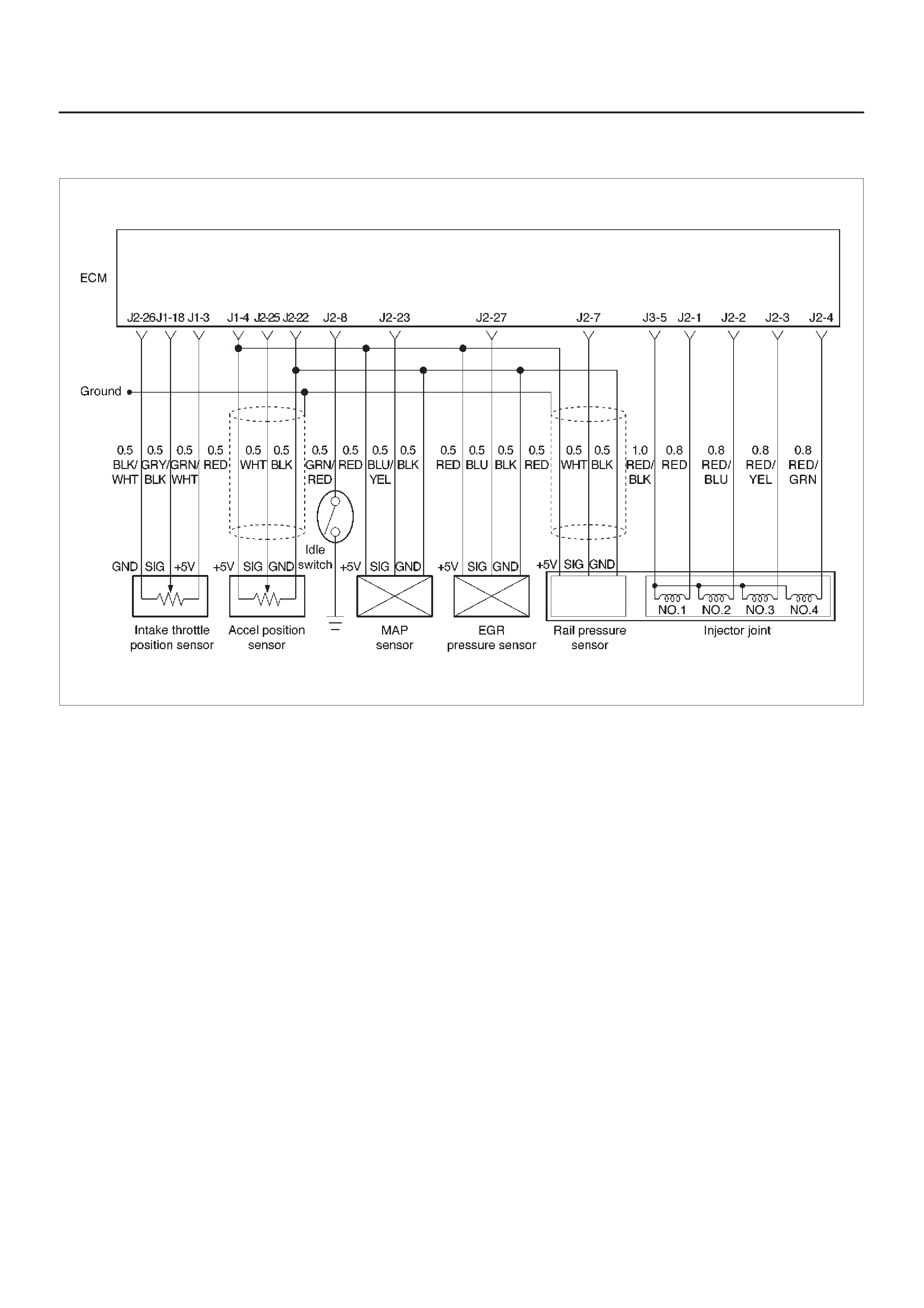
Diagnostic Trouble Code (DTC) P1195 (Flash DTC 61)
Rail Pressure System High Voltage
060RW134
Circuit Description
The rail pressure (RP) sensor responds to changes in oil
rail pressure.
The ECM monitors the RP signals for voltages outside the
normal range of the RP sensor . If the ECM detects a RP
signal voltage that is excessively low, DTC P1195 will be
set.
Action Taken When the DTC Sets
DThe ECM will store conditions which were present
when the DTC was set as Freeze Frame and in the
Failure Records data.
Conditions for Clearing the MIL/DTC
DDTC P1195 can be cleared by using the Tech 2 “Clear
Info” function or by disconnecting the ECM battery
feed.
Diagnostic Aids
Check for the following conditions:
DCheck for intermittent codes.
DPoor connection at ECM – Inspect harness connectors
for backed-out terminals, improper mating, broken
locks, improperly formed or damaged terminals, and
poor terminal-to-wire connection.
DDamaged harness – Inspect the wiring harness for
damage. If the harness appears to be OK, observe the
MAP display on the Tech 2 while moving connectors
and wiring harnesses related to the sensor . A change
in the display will indicate the location of the fault.
If DTC P1195 cannot be duplicated, the information
included in the Failure Records data can be useful in
determining vehicle mileage since the DTC was last set.
If it is determined that the DTC occurs intermittently,
performing the DTC P1195 Diagnostic Chart may isolate
the cause of the fault.

DTC P1195 – RP System High Voltage
Step Action Value(s) YesNo
1Was the “On-Board Diagnostic (OBD) System Check”
performed? —Go to
Step 2
Go to
OBD
System
Check
21. Engine is running.
2. Review and record Tech 2 Failure Records data.
3. Operate the vehicle within Failure Records
conditions as noted.
4. Using a Tech 2, monitor “DTC” info for DTC P1195.
Does the Tech 2 indicate DTC P1195 failed? —Go to
Step 3
Refer to
Diagnostic
Aids
3Connect a test light between B+ and the RP sensor
signal circuit at the RP sensor harness connector.
Is the RP value near the specified value. 0 V Go to
Step 4
Go to
Step 6
41. Ignition “OFF.”
2. Disconnect the ECM and check the ground circuit
for an open.
Was the ground circuit open? — Verify repair Go to
Step 5
5Check the ground circuit for a poor connection at the
ECM and replace the terminal if necessary.
Did the terminal require replacement? — Verify repair Go to
Step 6
6Check the RP sensor signal circuit for a poor
connection at the ECM and the RP sensor; replace the
terminal if necessary.
Did the terminal require replacement? — Verify repair Go to
Step 7
7Replace the ECM (Refer to the Data Programming in
Case of ECM change).
Is the action complete? — Verify repair Go to
Step 8
8Check the 2 way valve.
Was the 2 way valve darmage? —Replace the 2
way valve Go to
Step 9
9Replace the RPCV.
Is the action complete? — Verify repair Go to
Step 10
10 Replace the RP sensor.
Is the action complete? — Verify repair —
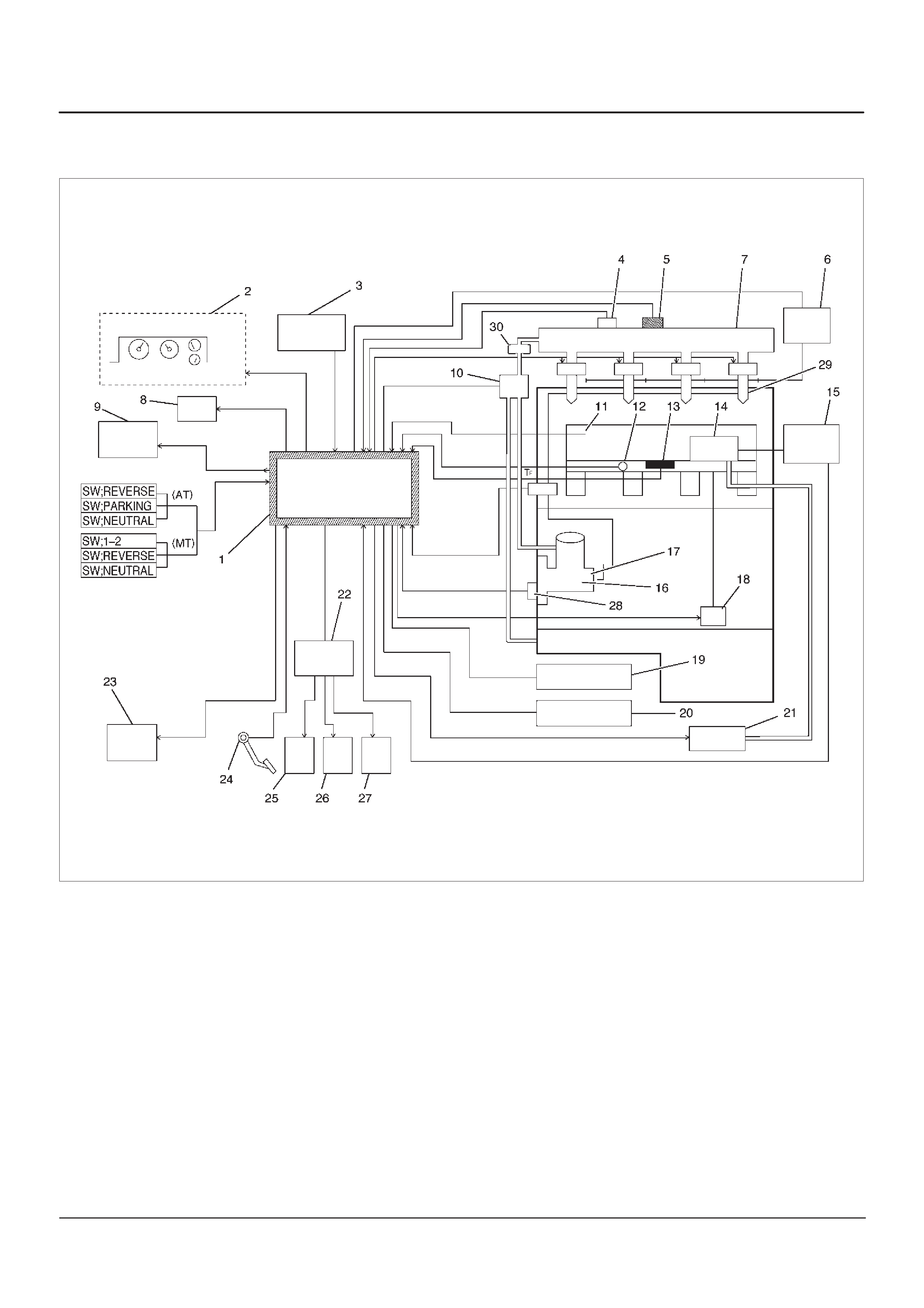
Diagnostic Trouble Code (DTC) P1196 (Flash DTC 62)
Rail Pressure System High Warning
060RW178
Legend
(1) ECM
(2) Meter Panel
(3) Battery
(4) Oil Temp Sensor
(5) Rail Pressure Sensor
(6) Glow Relay
(7) Oil Rail
(8) Tech–2
(9) A/C Comp Relay
(10) RPCV
(11) Intake Air Temp Sensor
(12) Engine Coolant Temp Sensor
(13) MAP Sensor
(14) EGR Valve
(15) EGR Pressure Sensor
(16) High Pressure Oil Pump
(17) Fuel Pump
(18) VSV
(19) EXH Throttle VSV1
(20) EXH Throttle VSV2
(21) EVRV
(22) Engine Harness Connector
(23) QWS Relay
(24) AP Sensor
(25) T.O.D
(26) ECT
(27) OBD
(28) TDC
(29) Injector
(30) Edge Filter

Circuit Description
The rail pressure control valve (RPCV) is built in the high
pressure oil circuit.
RPCV is an important device which is used to control oil
pressure in the HEUI system.
The circuit receives current through Engine 15A fuse from
the battery, current flowing in the order of RPCV.
Action Taken When the DTC Sets
DThe ECM will store conditions which were present
when the DTC was set as Freeze Frame and in the
Failure Records data.
Conditions for Clearing the MIL/DTC
DDTC P1196 can be cleared by using the Tech 2 “Clear
Info” function or by disconnecting the ECM battery
feed.
Diagnostic Aids
Check for the following conditions:
DPoor connection at ECM – Inspect harness connectors
for backed-out terminals, improper mating, broken
locks, improperly formed or damaged terminals, and
poor terminal-to-wire connection.
DDamaged harness – Inspect the wiring harness for
damage. If the harness appears to be OK, observe the
Rail Pressure Control display on the Tech 2 while
moving connectors and wiring harnesses related to the
Rail Pressure Control. A change in the Rail Pressure
Control display will indicate the location of the fault.
If DTC P1196 cannot be duplicated, the information
included in the Failure Records data can be useful in
determining vehicle mileage since the DTC was last set.
If it is determined that the DTC occurs intermittently.
Test Description
Number(s) below refer to the step number(s) on the
Diagnostic Chart.
2. Verifies that the fault is present.
DTC P1196 – RP System High Warning
Step Action Value(s) YesNo
1Was the “On-Board Diagnostic (OBD) System Check”
performed? —Go to
Step 2
Go to
OBD
System
Check
21. Engine is running.
2. Observe the “Rail Pressure Control” display on the
Tech 2.
Is the action correct? —Go to
Step 4
Go to
Step 3
3Replace the RPCV.
Is the action complete? — Verify repair Go to
Step 4
41. Engine is running.
2. Review and record Tech 2 Failure Records data.
3. Operate the vehicle within Failure Records
conditions as noted.
4. Using a Tech 2, monitor “ DTC” info for DTC P1 196.
Does the Tech 2 indicate DTC P1196 failed this
ignition? — Go to
Step 5
—
51. Check the 2 way valve.
2. Observe the “RP Control” display on the Tech 2.
Is the action correct? —Go to
Step 4
Go to
Step 6
6Replace the 2 way valve.
Is the action complete? — Verify repair —

Diagnostic Trouble Code (DTC) P0197 (Flash DTC 16)
Oil Temp Sensor Low Voltage
060RW129
Circuit Description
The engine oil temperature (OT) sensor is a thermistor
mounted in the oil rail. The Engine Control Module ECM
applies a voltage (about 5 volts) through a pull-up resistor
to the ECT signal circuit. When the engine oil is cold, the
sensor (thermistor) resistance is high, therefore the ECM
will measure a high signal voltage. As the engine oil
warms, the sensor resistance becomes lower, and the OT
signal voltage measured at the ECM drops.
Action Taken When the DTC Sets
DThe ECM will store conditions which were present
when the DTC was set as Freeze Frame and in the
Failure Records data.
Conditions for Clearing the MIL/DTC
DDTC P0197 can be cleared by using the Tech 2 “Clear
Info” function or by disconnecting the ECM battery
feed.
Diagnostic Aids
Check for the following conditions:
DPoor connection at ECM – Inspect harness connectors
for backed-out terminals, improper mating, broken
locks, improperly formed or damaged terminals, and
poor terminal-to-wire connection.
DDamaged harness – Inspect the wiring harness for
damage. If the harness appears to be OK, observe the
OT display on the Tech 2 while moving connectors and
wiring harnesses related to the OT sensor. A change
in the OT display will indicate the location of the fault.
If DTC P0197 cannot be duplicated, the information
included in the Failure Records data can be useful in
determining vehicle mileage since the DTC was last set.
If it is determined that the DTC occurs intermittently.

Test Description
Number(s) below refer to the step number(s) on the
Diagnostic Chart.
2. Verifies that the fault is present.
3. If DTC P0197 can be repeated only by duplicating
the Failure Records conditions, refer to the
“Temperature vs. Resistance Values” table. The
table may be used to test the OT sensor at various
temperatures to evaluate the possibility of a
“shifted” sensor that may be shorted above or below
a certain temperature. If this is the case, replace
the OT sensor. If the OT sensor appears to be OK,
the fault is intermittent; refer to
Diagnostic Aids
.
Engine Oil Temperature Sensor
°C°F Ohms
Temperature vs. Resistance Values
(approximate)
80 176 332
25 77 2796
15 59 4450
DTC P0197 – OT Sensor Low Voltage
Step Action Value(s) YesNo
1Was the “On-Board Diagnostic (OBD) System Check”
performed? —Go to
Step 2
Go to
OBD
System
Check
21. Ignition “ON,” engine “OFF.”
2. Observe the “Eng Oil Temp” display on the Tech 2.
Is the “Eng Oil Temp” below the specified value? 139°C
(282°F) Go to
Step 4
Go to
Step 3
31. Ignition “ON,” engine “OFF.”
2. Review and record Tech 2 Failure Records data.
3. Operate the vehicle within Failure Records
conditions as noted.
4. Using a Tech 2, monitor “ DTC” info for DTC P0197.
Does the Tech 2 indicate DTC P0197 failed this
ignition? — Go to
Step 4
Refer to
Diagnostic
Aids
41. Disconnect the OT sensor electrical connector.
2. Observe the “Eng Oil Temp” display on the Tech 2.
Is the “Eng Oil Temp” at the specified value? –39°C
(–38°F) Go to
Step 6
Go to
Step 5
51. Ignition “OFF.”
2. Disconnect the ECM and check the OT signal circuit
for a short to ground or a short to the sensor ground
circuit.
3. If the OT signal circuit is shorted. repair it as
necessary.
Was the OT signal circuit shorted to ground? — Verify repair Go to
Step 7
6Replace the OT sensor.
Is the action complete? — Verify repair —
7Replace the ECM (Refer to the Data Programming in
Case of ECM change).
Is the action complete? — Verify repair —
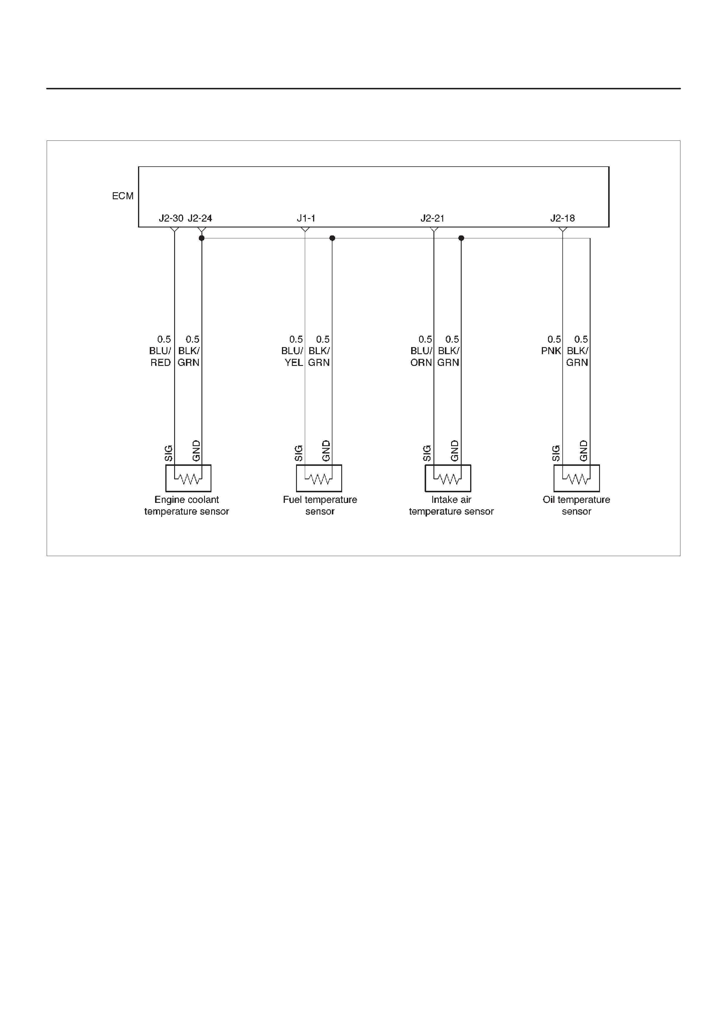
Diagnostic Trouble Code (DTC) P0198 (Flash DTC 16)
Oil Temp Sensor High Voltage
060RW129
Circuit Description
The engine oil temperature (OT) sensor is a thermistor
mounted in the oil rail. The Engine Control Module ECM
applies a voltage (about 5 volts) through a pull-up resistor
to the ECT signal circuit. When the engine oil is cold, the
sensor (thermistor) resistance is high, therefore the ECM
will measure a high signal voltage. As the engine oil
warms, the sensor resistance becomes lower, and the OT
signal voltage measured at the ECM drops.
Action Taken When the DTC Sets
DThe ECM will store conditions which were present
when the DTC was set as Freeze Frame and in the
Failure Records data.
Conditions for Clearing the MIL/DTC
DDTC P0198 can be cleared by using the Tech 2 “Clear
Info” function or by disconnecting the ECM battery
feed.
Diagnostic Aids
Check for the following conditions:
DPoor connection at ECM – Inspect harness connectors
for backed-out terminals, improper mating, broken
locks, improperly formed or damaged terminals, and
poor terminal-to-wire connection.
DDamaged harness – Inspect the wiring harness for
damage. If the harness appears to be OK, observe the
OT display on the Tech 2 while moving connectors and
wiring harnesses related to the OT sensor. A change
in the OT display will indicate the location of the fault.
If DTC P0198 cannot be duplicated, the information
included in the Failure Records data can be useful in
determining vehicle mileage since the DTC was last set.
If it is determined that the DTC occurs intermittently.

Test Description
Number(s) below refer to the step number(s) on the
Diagnostic Chart.
2. Verifies that the fault is present.
3. If DTC P0198 can be repeated only by duplicating
the Failure Records conditions, refer to the
“Temperature vs. Resistance Value” table. The
table may be used to test the OT sensor at various
temperatures to evaluate the possibility of a
“shifted” sensor that may be shorted above or below
a certain temperature. If this is the case, replace
the OT sensor. If the OT sensor appears to be OK,
the fault is intermittent; refer to
Diagnostic Aids
.
Engine Oil Temperature Sensor
°C°F Ohms
Temperature vs. Resistance Values
(approximate)
80 176 332
25 77 2796
15 59 4450
DTC P0198 – OT Sensor High Voltage
Step Action Value(s) YesNo
1Was the “On-Board Diagnostic (OBD) System Check”
performed? —Go to
Step 2
Go to
OBD
System
Check
21. Ignition “ON,” engine “OFF.”
2. Observe the “Eng Oil Temp” display on the Tech 2.
Is the “Eng Oil Temp” below the specified value? –39°C
(–38°F) Go to
Step 4
Go to
Step 3
31. Ignition “ON,” engine “OFF.”
2. Review and record Tech 2 Failure Records data.
3. Operate the vehicle within Failure Records
conditions as noted.
4. Using a Tech 2, monitor the “ DTC” info for DTC
P0198.
Does the Tech 2 indicate DTC P0198 failed? —Refer to
Test
Description
Refer to
Diagnostic
Aids
41. Disconnect the OT sensor electrical connector.
2. Jumper the OT signal circuit and the sensor ground
circuit together at the OT sensor harness
connector.
3. Observe the “Eng Oil Temp” display on the Tech 2.
Is the “Eng Oil Temp” at the specified value? 140°C
(284°F) Go to
Step 6
Go to
Step 5
51. Jumper the OT signal circuit at the OT sensor
harness connector to chassis ground.
2. Observe the “Eng Oil Temp” display on the Tech 2.
Is the “Eng Oil Temp” at the specified value? 140°C
(284°F) Go to
Step 7
Go to
Step 8
6Check for poor connections at the OT sensor and
replace terminals if necessary.
Did any terminals require replacement? — Verify repair Go to
Step 10
71. Ignition “OFF.”
2. Disconnect the ECM, and check the OT sensor
ground circuit for an open.
3. If the OT sensor ground circuit is open, repair it as
necessary.
Was the OT sensor ground circuit open? — Verify repair Go to
Step 9

DTC P0198 – OT Sensor High Voltage (Cont'd)
Step NoYesValue(s)Action
81. Ignition “OFF.”
2. Disconnect the OT, and check the OT signal circuit
for an open.
3. If the OT sensor signal circuit is open, repair it as
necessary.
Was the OT signal circuit open? — Verify repair Go to
Step 9
9Check for a poor sensor ground or OT signal circuit
terminal connection at the ECM and replace
terminal(s) if necessary.
Did any of the terminals need to be replaced? — Verify repair Go to
Step 11
10 Replace the ECT sensor.
Is the action complete? — Verify repair —
11 Replace the ECM (Refer to the Data Programming in
Case of ECM change).
Is the action complete? — Verify repair —

Diagnostic Trouble Code (DTC) P0201 (Flash DTC 51)
Injector # 1 Circuit Fault
060RW134
Circuit Description
The Engine Control Module ECM has four individual
injector driver circuits. Each controls an injector . When a
driver circuit is grounded by the ECM, the injector is
activated. The ECM monitors the current in each driver
circuit. The voltage on each driver is monitored to detect
a fault. If the voltage is not what the ECM expects to
monitor on the circuit, a DTC is set. This DTC is also set if
an injector driver is shorted to voltage or if there is an open
circuit.
Action Taken When the DTC Sets
DThe ECM will store conditions which were present
when the DTC was set as Freeze Frame and in the
Failure Records data.
Conditions for Clearing the MIL/DTC
DDTC P0201 can be cleared by using the Tech 2 “Clear
Info” function or by disconnecting the ECM battery
feed.
Diagnostic Aids
An injector driver circuit that is open or shorted to voltage
will cause a DTC P0201 to set.
Test Description
The number(s) below refer to the step number(s) on the
Diagnostic Chart.
3. This step determines if DTC P0201 is the result of a
hard failure or an intermittent condition.
Injector Test
This test is conducted to make it sure that appropriate
electric signals are being sent to injectors Nos. 1–4.
Tech–2 must be used for this test.
Test Procedure:
1. Connect Tech–2 to the vehicle DLC.
2. Set Ignition Switch to the “ON” position.
3. Select Control Test.
4. Select Injector Test.
5. Send instructions to each injector (Switch on),
making sure of injector working noise.
NOTE: If injector working noise (Clink) can hardly be
confirmed, remove the engine head cover noise
insulation.
Refer to Section 6A.
6. In the injector whose working noise has been
confirmed, its electric circuit can be regarded as
normal.
As for the injector whose working noise has not
been confirmed, its electric circuit or the injector
proper is faulty.

DTC P0201 – Injector # 1 Circuit Fault
Step Action Value(s) YesNo
1Was the “On-Board Diagnostic (OBD) System Check”
performed? —Go to
Step 2
Go to
OBD
System
Check
2Will the engine start?
—Go to
Step 3
Go to
Engine
Cranks But
Will Not Run
chart
31. Install the Tech 2. Clear the DTC.
2. Idle the engine for one minute.
Does DTC P0201 reset? —Go to
Step 5
Go to
Step 4
41. Review the Freeze Frame data with the ignition
“ON” and the engine “OFF” and note the
parameters.
2. Operate the vehicle within the Freeze Frame
conditions as noted.
Does P0201 reset? —Go to
Step 5
—
5Check the Injector test.
Does the working noise confirm? —Go to
Step 6
Go to
Step 7
61. Install the Tech 2. Clear the DTC.
2. Idle the engine for one minute.
Dose DTC P0201 reset? — Verify repair Go to
Step 7
7Check for an open circuit between the injector
connector and the ECM.
Was there an open circuit? —Go to
Step 8
Go to
Step 9
8Repair the open circuit.
Is the action complete? — Verify repair —
9Replace the ECM (Refer to the Data Programming in
Case of ECM change).
Is the action complete? — Verify repair Go to
Step 10
10 Replace the Injector (Refer to the Injector Group Sign
Programming).
Is the action complete? — Verify repair —

Diagnostic Trouble Code (DTC) P0202 (Flash DTC 52)
Injector # 2 Circuit Fault
060RW134
Circuit Description
The Engine Control Module ECM has four individual
injector driver circuits. Each controls an injector. When a
driver circuit is grounded by the ECM, the injector is
activated. The ECM monitors the current in each driver
circuit. The voltage on each driver is monitored to detect
a fault. If the voltage is not what the ECM expects to
monitor on the circuit, a DTC is set. This DTC is also set if
an injector driver is shorted to voltage or if there is an open
circuit.
Action Taken When the DTC Sets
DThe ECM will store conditions which were present
when the DTC was set as Freeze Frame and in the
Failure Records data.
Conditions for Clearing the MIL/DTC
DDTC P0202 can be cleared by using the Tech 2 “Clear
Info” function or by disconnecting the ECM battery
feed.
Diagnostic Aids
An injector driver circuit that is open or shorted to voltage
will cause a DTC P0202 to set.
Test Description
The number(s) below refer to the step number(s) on the
Diagnostic Chart.
3. This step determines if DTC P0202 is the result of a
hard failure or an intermittent condition.
Injector Test
This test is conducted to make it sure that appropriate
electric signals are being sent to injectors Nos. 1–4.
Tech–2 must be used for this test.
Test Procedure:
1.Connect Tech–2 to the vehicle DLC.
2.Set Ignition Switch to the “ON” position.
3.Select Control Test.
4.Select Injector Test.
5.Send instructions to each injector (Switch on),
making sure of injector working noise.
NOTE:If injector working noise (Clink) can hardly be
confirmed, remove the engine head cover noise
insulation.
Refer to Section 6A.
6. In the injector whose working noise has been
confirmed, its electric circuit can be regarded as
normal.
As for the injector whose working noise has not
been confirmed, its electric circuit or the injector
proper is faulty.

DTC P0202 – Injector # 2 Circuit Fault
Step Action Value(s) YesNo
1Was the “On-Board Diagnostic (OBD) System Check”
performed? —Go to
Step 2
Go to
OBD
System
Check
2Will the engine start?
—Go to
Step 3
Go to
Engine
Cranks But
Will Not Run
chart
31. Install the Tech 2. Clear the DTC.
2. Idle the engine for one minute.
Does DTC P0202 reset? —Go to
Step 5
Go to
Step 4
41. Review the Freeze Frame data with the ignition
“ON” and the engine “OFF” and note the
parameters.
2. Operate the vehicle within the Freeze Frame
conditions as noted.
Does P0202 reset? —Go to
Step 5
—
5Check the Injector test.
Does the working noise confirm? —Go to
Step 6
Go to
Step 7
61. Install the Tech 2. Clear the DTC.
2. Idle the engine for one minute.
Dose DTC P0202 reset? — Verify repair Go to
Step 7
7Check for an open circuit between the injector
connector and the ECM.
Was there an open circuit? —Go to
Step 8
Go to
Step 9
8Repair the open circuit.
Is the action complete? — Verify repair —
9Replace the ECM (Refer to the Data Programming in
Case of ECM change).
Is the action complete? — Verify repair Go to
Step 10
10 Replace the Injector (Refer to the Injector Group Sign
Programming).
Is the action complete? — Verify repair —

Diagnostic Trouble Code (DTC) P0203 (Flash DTC 52)
Injector # 3 Circuit Fault
060RW134
Circuit Description
The Engine Control Module ECM has four individual
injector driver circuits. Each controls an injector. When
the driver circuit is grounded by the ECM, the injector is
activated. The ECM monitors the current in each driver
circuit. The voltage on each driver is monitored to detect
a fault. If the voltage is not what the ECM expects to
monitor on the circuit, a DTC is set. This DTC is also set if
an injector driver is shorted to voltage or if there is an open
circuit.
Action Taken When the DTC Sets
DThe ECM will store conditions which were present
when the DTC was set as Freeze Frame and in the
Failure Records data.
Conditions for Clearing the MIL/DTC
DDTC P0203 can be cleared by using the Tech 2 “Clear
Info” function or by disconnecting the ECM battery
feed.
Diagnostic Aids
An injector driver circuit that is open or shorted to voltage
will cause a DTC P0203 to set.
Test Description
The number(s) below refer to the step number(s) on the
Diagnostic Chart.
3. This step determines if DTC P0203 is the result of a
hard failure or an intermittent condition.
Injector Test
This test is conducted to make it sure that appropriate
electric signals are being sent to injectors Nos. 1–4.
Tech–2 must be used for this test.
Test Procedure:
1.Connect Tech–2 to the vehicle DLC.
2.Set Ignition Switch to the “ON” position.
3.Select Control Test.
4.Select Injector Test.
5.Send instructions to each injector (Switch on),
making sure of injector working noise.
NOTE:If injector working noise (Clink) can hardly be
confirmed, remove the engine head cover noise
insulation.
Refer to Section 6A.
6. In the injector whose working noise has been
confirmed, its electric circuit can be regarded as
normal.
As for the injector whose working noise has not
been confirmed, its electric circuit or the injector
proper is faulty.

DTC P0203 – Injector # 3 Circuit Fault
Step Action Value(s) YesNo
1Was the “On-Board Diagnostic (OBD) System Check”
performed? —Go to
Step 2
Go to
OBD
System
Check
2Will the engine start?
—Go to
Step 3
Go to
Engine
Cranks But
Will Not Run
chart
31. Install the Tech 2. Clear the DTC.
2. Idle the engine for one minute.
Does DTC P0203 reset? —Go to
Step 5
Go to
Step 4
41. Review the Freeze Frame data with the ignition
“ON” and the engine “OFF” and note the
parameters.
2. Operate the vehicle within the Freeze Frame
conditions as noted.
Does P0203 reset? —Go to
Step 5
—
5Check the Injector test.
Does the working noise confirm? —Go to
Step 6
Go to
Step 7
61. Install the Tech 2. Clear the DTC.
2. Idle the engine for one minute.
Dose DTC P0203 reset? — Verify repair Go to
Step 7
7Check for an open circuit between the injector
connector and the ECM.
Was there an open circuit? —Go to
Step 8
Go to
Step 9
8Repair the open circuit.
Is the action complete? — Verify repair —
9Replace the ECM (Refer to the Data Programming in
Case of ECM change).
Is the action complete? — Verify repair Go to
Step 10
10 Replace the Injector (Refer to the Injector Group Sign
Programming).
Is the action complete? — Verify repair —

Diagnostic Trouble Code (DTC) P0204 (Flash DTC 54)
Injector # 4 Circuit Fault
060RW134
Circuit Description
The Engine Control Module ECM has four individual
injector driver circuits. Each controls an injector. When
the driver circuit is grounded by the ECM, the injector is
activated. The ECM monitors the current in each driver
circuit. The voltage on each driver is monitored to detect
a fault. If the voltage is not what the ECM expects to
monitor on the circuit, a DTC is set. This DTC is also set if
an injector driver is shorted to voltage or if there is an open
circuit.
Action Taken When the DTC Sets
DThe ECM will store conditions which were present
when the DTC was set as Freeze Frame and in the
Failure Records data.
Conditions for Clearing the MIL/DTC
DDTC P0204 can be cleared by using the Tech 2 “Clear
Info” function or by disconnecting the ECM battery
feed.
Diagnostic Aids
An injector driver circuit that is open or shorted to voltage
will cause a DTC P0204 to set.
Test Description
The number(s) below refer to the step number(s) on the
Diagnostic Chart.
3. This step determines if DTC P0204 is the result of a
hard failure or an intermittent condition.
Injector Test
This test is conducted to make it sure that appropriate
electric signals are being sent to injectors Nos. 1–4.
Tech–2 must be used for this test.
Test Procedure:
1.Connect Tech–2 to the vehicle DLC.
2.Set Ignition Switch to the “ON” position.
3.Select Control Test.
4.Select Injector Test.
5.Send instructions to each injector (Switch on),
making sure of injector working noise.
NOTE:If injector working noise (Clink) can hardly be
confirmed, remove the engine head cover noise
insulation.
Refer to Section 6A.
6. In the injector whose working noise has been
confirmed, its electric circuit can be regarded as
normal.
As for the injector whose working noise has not
been confirmed, its electric circuit or the injector
proper is faulty.

DTC P0204 – Injector #4 Circuit Fault
Step Action Value(s) YesNo
1Was the “On-Board Diagnostic (OBD) System Check”
performed? —Go to
Step 2
Go to
OBD
System
Check
2Will the engine start?
—Go to
Step 3
Go to
Engine
Cranks But
Will Not Run
chart
31. Install the Tech 2. Clear the DTC.
2. Idle the engine for one minute.
Does DTC P0204 reset? —Go to
Step 5
Go to
Step 4
41. Review the Freeze Frame data with the ignition
“ON” and the engine “OFF” and note the
parameters.
2. Operate the vehicle within the Freeze Frame
conditions as noted.
Does P0204 reset? —Go to
Step 5
—
5Check the Injector test.
Does the working noise confirm? —Go to
Step 6
Go to
Step 7
61. Install the Tech 2. Clear the DTC.
2. Idle the engine for one minute.
Dose DTC P0204 reset? — Verify repair Go to
Step 7
7Check for an open circuit between the injector
connector and the ECM.
Was there an open circuit? —Go to
Step 8
Go to
Step 9
8Repair the open circuit.
Is the action complete? — Verify repair —
9Is the action complete? — Verify repair Go to
Step 10
10 Replace the Injector (Refer to the Injector Group Sign
Programming).
Is the action complete? — Verify repair —

Diagnostic Trouble Code (DTC) P0217 (Flash DTC 22)
High Coolant Temp Waring
060RW129
Circuit Description
The engine coolant temperature (ECT) sensor is a
thermistor mounted on a coolant crossover pipe at the
rear of the engine. The Engine Control Module ECM
applies a voltage (about 5 volts) through a pull-up resistor
to the ECT signal circuit. When the engine coolant is cold,
the sensor (thermistor) resistance is high, therefore the
ECM will measure a high signal voltage. As the engine
coolant warms, the sensor resistance becomes lower,
and the ECT signal voltage measured at the ECM drops.
Action Taken When the DTC Sets
DThe ECM will store conditions which were present
when the DTC was set as Freeze Frame and in the
Failure Records data.
Conditions for Clearing the MIL/DTC
DDTC P0217 can be cleared by using the Tech 2 “Clear
Info” function or by disconnecting the ECM battery
feed.
Diagnostic Aids
Check for the following conditions:
DPoor connection at ECM – Inspect harness connectors
for backed-out terminals, improper mating, broken
locks, improperly formed or damaged terminals, and
poor terminal-to-wire connection.
DDamaged harness – Inspect the wiring harness for
damage. If the harness appears to be OK, observe the
ECT display on the Tech 2 while moving connectors
and wiring harnesses related to the ECT sensor. A
change in the ECT display will indicate the location of
the fault.
If DTC P0217 cannot be duplicated, the information
included in the Failure Records data can be useful in
determining vehicle mileage since the DTC was last set.
If it is determined that the DTC occurs intermittently.
Test Description
Number(s) below refer to the step number(s) on the
Diagnostic Chart.
2. Verifies that the fault is present.
3. If DTC P0117 can be repeated only by duplicating
the Failure Records conditions, refer to the
“Temperature vs. Resistance Values” table. The
table may be used to test the ECT sensor at various
temperatures to evaluate the possibility of a
“shifted” sensor that may be shorted above or below
a certain temperature. If this is the case, replace
the ECT sensor. If the ECT sensor appears to be
OK, the fault is intermittent; refer to
Diagnostic Aids
.

DTC P0217 – High Coolant Temp Waring
Step Action Value(s) YesNo
1Was the “On-Board Diagnostic (OBD) System Check”
performed? —Go to
Step 2
Go to
OBD
System
Check
21. Ignition “ON,” engine “OFF.”
2. Observe the “Eng Cool T emp” display on the T ech 2.
Is the “Eng Cool Temp” below the specified value? 110°CGo to
Step 6
Go to
Step 3
3Check the engine coolant quantity
Was the engine coolant appropriate quantity? —Go to
Step 6
Go to
Step 4
4Check a leak from EC circuit.
Was the EC leaked from EC circuit? —Go to
Step 5
Go to
Step 6
5Repair the EC circuit.
Is the action complete? — Verify repair —
61. Ignition “ON,” engine “OFF.”
2. Review and record Tech 2 Failure Records data.
3. Operate the vehicle within Failure Records
conditions as noted.
4. Using a Tech 2, monitor “ DTC” info for DTC P0217.
Does the Tech 2 indicate DTC P0217 failed this
ignition? — Go to
Step 7
—
7 1. Ignition “OFF”.
2. Check the Thermostat.
3. If the Thermostat is damaged, repair it as
necessary.
Was the Thermostat damaged? —Go to
Step 8
Go to
Step 9
8Replace the Thermostat.
Is the action complete? — Verify repair —
91. Check the Radiator.
2. If the Radiator is damaged, repair it as necessary.
Was the Radiator damaged? —Go to
Step 10
Go to
Step 11
10 Repair the Radiator.
Is the action complete? — Verify repair —
11 1. Check the EC circuit in the Engine.
2. Observe the “Eng Data List” display on the Tech 2.
3. If the EC circuit in the Engine is damaged, repair it
as necessary.
Was the EC circuit damaged? Refer to Data
List Go to
Step 12
Go to
Step 6
12 Repair the EC circuit.
Is the action complete? — Verify repair —

Diagnostic Trouble Code (DTC) P1217 (Flash DTC 36)
High Oil Temp Warning
060RW129
Circuit Description
The engine oil temperature (OT) sensor is a thermistor
mounted on a oil manifold. The Engine Control Module
ECM applies a voltage (about 5 volts) through a pull-up
resistor to the OT signal circuit. When the engine oil is
cold, the sensor (thermistor) resistance is high, therefore
the ECM will measure a high signal voltage. As the
engine oil warms, the sensor resistance becomes lower,
and the OT signal voltage measured at the ECM drops.
Action Taken When the DTC Sets
DThe ECM will store conditions which were present
when the DTC was set as Freeze Frame and in the
Failure Records data.
Conditions for Clearing the MIL/DTC
DDTC P1217 can be cleared by using the Tech 2 “Clear
Info” function or by disconnecting the ECM battery
feed.
Diagnostic Aids
Check for the following conditions:
DPoor connection at ECM – Inspect harness connectors
for backed-out terminals, improper mating, broken
locks, improperly formed or damaged terminals, and
poor terminal-to-wire connection.
DDamaged harness – Inspect the wiring harness for
damage.
DHigh Oil Temperature Warning may sometimes be
given due to High Coolant Temp Warning. On this
occasion, recognize DTC P0217 and give priority to
High Coolant Temp Warning.

DTC P1217 – High Oil Temp Warning
Step Action Value(s) YesNo
1Was the “On-Board Diagnostic (OBD) System Check”
performed? —Go to
Step 2
Go to
OBD
System
Check
21. Ignition “ON,” engine “OFF.”
2. Observe the “Eng Cool T emp” display on the T ech 2.
Is the “Eng Cool Temp” below the specified value? 139°C
(282°F) Go to
Step 4
Go to
Step 3
31. Ignition “ON,” engine “OFF.”
2. Review and record Tech 2 Failure Records data.
3. Using a Tech 2, monitor “ DTC” info for DTC P0217.
Does the Tech 2 indicate DTC P0217 failed this
ignition? — Go to
Step 4
Refer to
Diagnostic
Aids
41. Ignition “ON,” engine “OFF.”
2. Review and record Tech 2 Failure Records data.
3. Operate the vehicle within Failure Records
conditions as noted.
4. Using a Tech 2, monitor “ DTC” info for DTC P1217.
Does the Tech 2 indicate DTC P1217 failed this
ignition? — Go to
Step 5
Refer to
Diagnostic
Aids
51. Measure the engine oil quantity by oil level gage.
2. If the engine oil is shortage, fill up it as necessary.
Was the engine oil is shortaged? — Verify repair Go to
Step 6
6Replace the oil temp sensor.
Is the action complete? — Verify repair Go to
Step 7
7Replace the oil cooler.
Is the action complete? — Verify repair —

Diagnostic Trouble Code (DTC) P0219 (Flash DTC 11) Engine Over Speed
Warning
060RW133
Circuit Description
The CKP reference signal is produced by the crankshaft
position (CKP) sensor. During one crankshaft
revolution, CKP crankshaft reference pulses will be
produced. The Engine Control Module ECM uses the
CKP reference signal to calculate engine RPM and
crankshaft position.
Ac ti on Taken Wh en th e DTC Sets
• The ECM will store conditions which were present
when the DTC was set as Freeze Frame and in the
Failure Records d ata.
Conditions for Clearing the MIL/DTC
• DTC P0219 can be cleared by using the Tech 2
“Clear Info” function or by disconnecting the ECM
battery feed.
Diagnostic Aids
Check for:
• Poor connection – Inspect the CKP harness and
connectors for improper mating, broken locks,
improperly formed or damaged terminals, and poor
terminal-to-wire connection.
• Damaged X57 – Inspect the X57 for damage.

DTC P0219 – Engine Over Speed Warning
Step Action Value(s) Yes No
1 W as the “On-Board Diagnostic (OBD) System Check”
performed? — Go to Step 2 Go to OBD
System Check
2 Check the responsibility.
W as the driver responsibility? — Go to Step 3 Go to Chart 4
3 1. Review and record Failure Records information.
2. Clear DTC P0219.
3. Start the engine and idle for 1 minute.
4. Observe DTCs.
Is DTC P0219 set? — Go to Step 4 —
4 Observe the AP value displayed on the Tech 2.
Is the AP value near the specified value? (Idling720r.p.
m) 0% Go to Step 3 Go to Step 5
5 Observe the Engine speed displayed on the Tech 2.
Is the Engine speed near the specified value? (Idling)720r.p.
mGo to Step 7 Go to Step 6
6 1. Check the CKP sensor.
2. Ignition “ON.”
3. Using a DVM, verify that 12 V reference and
ground are being supplied at the sensor connector
(ECM side).
Are 11-13 volts and ground available at the sensor? — Go to Step 9 Go to Step 7
7 1. Ignition “ON.”
2. With a DVM, backprobe the ECM connector 12 V
reference and ground connections.
Are 12 V reference and ground available at the ECM? — Go to Step 8 Go to Step 13
8 Check 12 V reference or ground between the CKP
sensor and ECM and repair the open circuit, short to
ground or short to voltage.
Is the action complete? Verify repair —
9 1. Ignition “OFF.”
2. Disconnect the ECM and CKP sensor.
3. Check for an open or a short to ground in the CKP
signal circuit between the CKP sensor connector
and the ECM harness connector.
4. If a problem is found, repair as necessary.
W as a problem found? — V erify repair Go to Step 10
10 1. Reconnect the ECM and CKP sensor.
2. Connect a DVM to measure voltage on the CKP
signal circuit at the ECM connector.
3. Observe the voltage while cranking the engine.
Is the voltage near the specified value? — Go to Step 13 Go to Step 11
1 1 Check the connections at the CKP sensor and replace
the terminals if necessary.
Did any terminals require replacement? 6 V Verify repair Go to Step 12
12 Replace the CKP sensor.
Is the action complete? — Verify repair —
13 Check the connections at the ECM and replace the
terminals if necessary.
Did any terminals require replacement? — Verify repair Go to Step 14
14 Check the X57 signal plate.
Is the X57 signal plate damage? — Go to Step 15 Go to Step 3
15 Replace the X57 signal plate.
Is the action complete? — Verify repair Go to Step 2
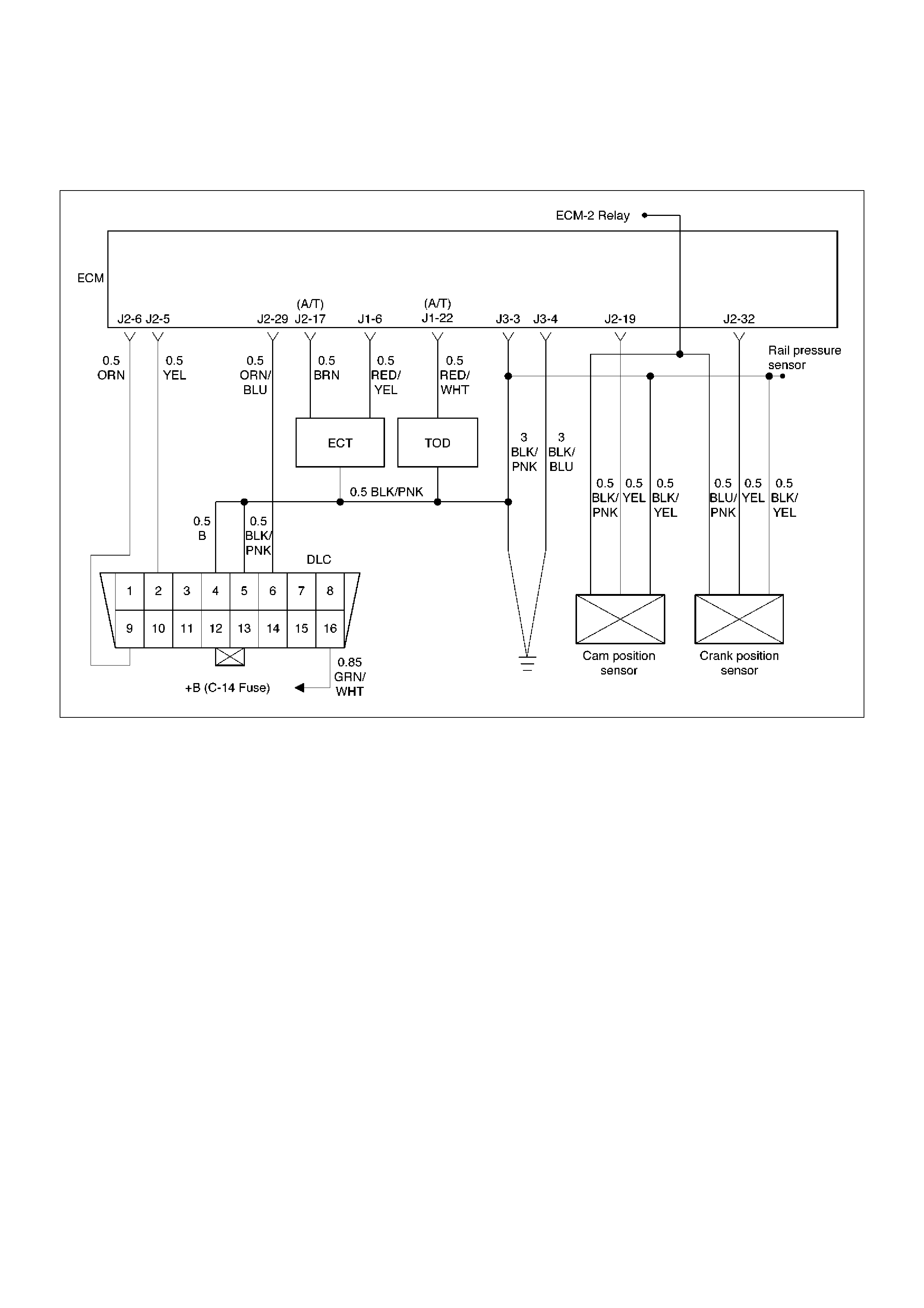
Diagnostic Trouble Code (DTC) P0336 (Flash DTC 43) CKP (Crank Position)
Sensor Out of Synchro
060RW133
Circuit Description
The CKP reference signal is produced by the crankshaft
position (CKP) sensor. During one crankshaft
revolution, crankshaft pulses will be produced. The
Engine Control Module ECM uses the CKP reference
signal to calculate engine RPM and crankshaft position.
If the ECM receives an incorrect number of pulses on
the CKP reference circuit, DTC P0336 will set.
Ac ti on Taken Wh en th e DTC Sets
• The ECM will store conditions which were present
when the DTC was set as Freeze Frame and in the
Failure Records d ata.
Conditions for Clearing the MIL/DTC
• DTC P0336 can be cleared by using the Tech 2
“Clear DTC Info” function or by disconnecting the
ECM battery feed.
Diagnostic Aids
An intermittent may be caused by a poor connection,
rubbed–through wire insulation or a wire broken inside
the insulation. Check for:
• Poor connection – Inspect the ECM harness and
connectors for improper mating, broken locks,
improperly formed or damaged terminals, and poor
terminal-to-wire connection.
• Damaged harness – Inspect the wiring harness for
damage. If the harness appears to be OK,
disconnect the ECM, turn the ignition on and observe
a voltmeter connected to the CKP reference circuit at
the ECM harness connector while moving connectors
and wiring harnesses related to the ECM. A change
in voltage will indicate the location of the fault.
Reviewing the Failure Records vehicle mileage since
the diagnostic test last failed may help determine how
often the condition that caused the DTC to be set
occurs. This may assist in diagnosing the condition.

DTC P0336 – CKP Sensor Out of Synchro
Step Action Value(s) Yes No
1 W as the “On-Board Diagnostic (OBD) System Check”
performed? —Go to Step 2 Go to OBD
System Check
2 Attempt to start the engine.
Does the engine start? —Go to Step 3
Go to “Engine
Cranks But Will
Not Run” ch art
3 1. Review and record Failure Records information.
2. Clear DTC P0336.
3. Start the engine and idle for 1 minute.
4. Observe DTCs.
Is DTC P0336 set? — Go to Step 4 Refer to
Diagnostic Aids
4 1. Disconnect the ECM and CKP sensor.
2. Check for an open or a short to ground in the CKP
signal circuit between the CKP sensor connector
and the ECM harness connector.
3. If a problem is found, repair as necessary.
W as a problem found? — Verify repair Go to Step 5
5 1. Reconnect the ECM and CKP sensor.
2. Connect a DVM to measure voltage on the CKP
signal circuit at the ECM connector.
3. Observe the voltage while cranking the engine.
Is the voltage near the specified value? 6 V Go to Step 8 Go to Step 6
6 Check the connections at the CKP sensor and replace
the terminals if necessary.
Did any terminals require replacement? — Verify repair Go to Step 7
7 Replace the CKP sensor.
Is the action complete? — Verify repair Go to Step 8
8 Check connections at the ECM and replace the
terminals if necessary.
Did any terminals require replacement? — Verify repair Go to Step 9
9 Replace the ECM.
Note:
• Th e replac ement EC M must be pr ogram med. Refe r
to Section 0C1 - Service Programming System for
instructions on this procedure.
• The ECU must be linked to the Immobiliser System.
Refer to Section 11B - Engine Immobiliser for
programmi ng ins tr ucti ons .
Is the action complete? — Verify repair —

Diagnostic Trouble Code (DTC) P0337 (Flash DTC 43) CKP (Crank Position)
Sensor No Signal (EXCEPT MY1999 - MY2002 VEHICLES)
060RW133
Circuit Description
The CKP reference signal is produced by the crankshaft
position (CKP) sensor. During one crankshaft
revolution, CKP crankshaft reference pulses will be
produced. The Engine Control Module ECM uses the
CKP reference signal to calculate engine RPM and
crankshaft position. If the ECM does not receive pulses
on the CKP reference circuit, DTC P0337 will set.
Ac ti on Taken Wh en th e DTC Sets
• The ECM will store conditions which were present
when the DTC was set as Freeze Frame and in the
Failure Records d ata.
Conditions for Clearing the MIL/DTC
• DTC P0337 can be cleared by using the Tech 2
“Clear DTC Info” function or by disconnecting the
ECM battery feed.
Diagnostic Aids
An intermittent may be caused by a poor connection,
rubbed-through wire insulation or a wire broken inside
the insulation. Check for:
• Poor connection – Inspect the ECM harness and
connectors for improper mating, broken locks,
improperly formed or damaged terminals, and poor
terminal-to-wire connection.
• Damaged harness – Inspect the wiring harness for
damage. If the harness appears to be OK,
disconnect the ECM, turn the ignition on and observe
a voltmeter connected to the CKP reference circuit at
the ECM harness connector while moving connectors
and wiring harnesses related to the ICM. A change in
voltage will indicate the location of the fault.
Reviewing the Failure Records vehicle mileage since
the diagnostic test last failed may help determine how
often the condition that caused the DTC to be set
occurs. This may assist in diagnosing the condition.

DTC P0337 – CKP Se nsor No Signal
Step Action Value(s) Yes No
1 Was the “On-Board Diagnostic (OBD) System Check”
performed? — Go to Step 2 Go to OBD
System Check
2 Attempt to start the engine.
Does the engine start? —Go to Step 3
Go to Engine
Cranks But Will
Not Run
3 1. Review and record Failure Records information.
2. Clear DTC P0337.
3. Start the engine and idle for 1 minute.
4. Observe DTCs.
Is DTC P0337 set? — Go to Step 4 Refer to
Diagnostic Aid
4 1. Disconnect the CKP sensor.
2. Ignition “ON.”
3. Using a DVM, verify that 12 V reference and ground
are being supplied at the sensor connector (ECM
side).
Are 11-12 volts and ground available at the sensor? — Go to Step 7 Go to Step 5
5 1. Ignition “ON.”
2. With a DVM, backprobe the ECM connector 12 V
reference and ground connections.
Are 12 V reference and ground available at the ECM? — Go to Step 6 Go to Step 11
6 Check 12 V reference or ground between the CKP
sensor and ECM and repair the open circuit, short to
ground or short to voltage.
Is the action complete? Verify repair —
7 1. Ignition “OFF.”
2. Disconnect the ECM and CKP sensor.
3. Check for an open or a short to ground in the CKP
signal circuit between the CKP sensor connector and
the ECM harness connector.
4. If a problem is found, repair as necessary.
Was a problem found? — Verify repair Go to Step 8
8 1. Reconnect the ECM and CKP sensor.
2. Connect a DVM to measure voltage on the CKP
signal circuit at the ECM connector.
3. Observe the voltage while cranking the engine.
Is the voltage near the specified value? 2.5V Go to Step 11 Go to Step 9
9 Check the connections at the CKP sensor and replace
the terminals if necessary.
Did any terminals require replacement? — Verify repair Go to Step 10
10 Replace the CKP sensor. Use caution and avoid hot oil
that may drip out.
Is the action complete? — Verify repair —
11 Check the connections at the ECM and replace the
terminals if necessary.
Did any terminals require replacement? — Verify repair Go to Step 12
12 Replace the ECM.
Note:
The replacement ECM must be programmed. Refer to
the Section 0C1 -Service Programming System for
instructions on this procedure.
The ECU must be linked to the Immobiliser System.
Refer to Section 11B - Engine Immobiliser for
programming instructions.
Is the action complete? —Verify repair —
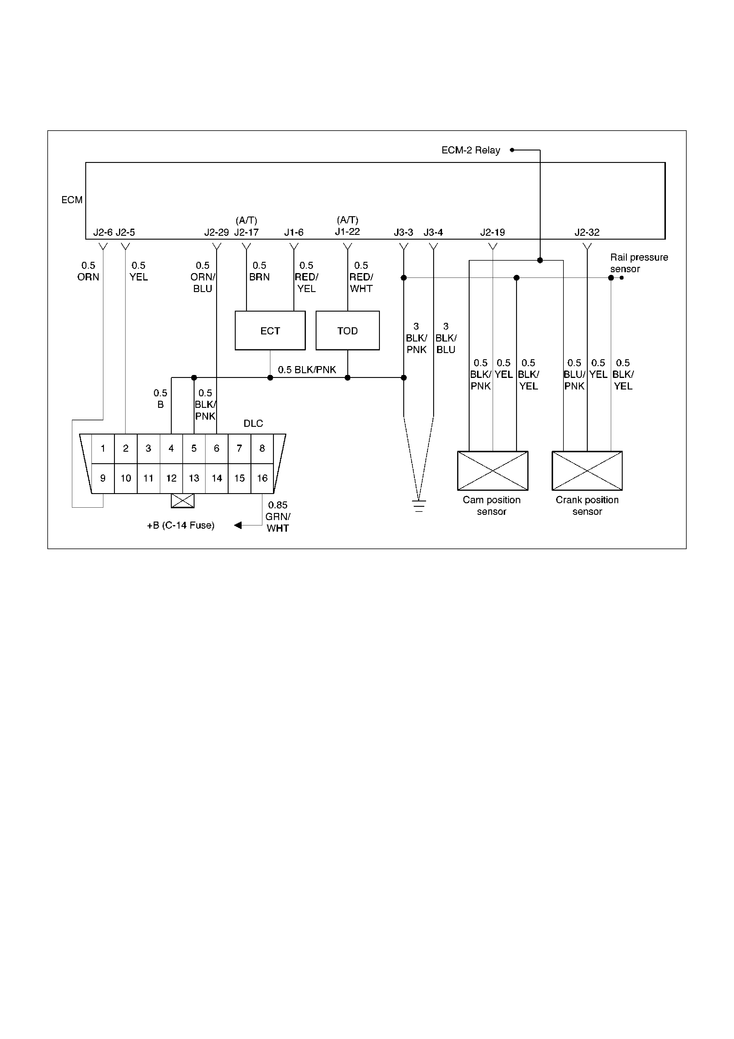
CKP (Crank Position) Sensor No Signal (MY1999 - MY2002 VEHICLES ONLY)
060RW133
Circuit Description
The CKP reference signal is produced by the crankshaft
position (CKP) sensor. During one crankshaft
revolution, CKP crankshaft reference pulses will be
produced. The Engine Control Module ECM uses the
CKP reference signal to calculate engine RPM and
crankshaft position.
The DTC for this condition (DTC P0337) was deleted
from the ECM software during MY1998 production and
up until the end of MY2002 production.
Quick Check
• The engine will not start and run without the X57 CKP
reference signal.
• TECH 2 wil not display an engine RPM signal during
crank.
Diagnostic Aids
An intermittent may be caused by a poor connection,
rubbed-through wire insulation or a wire broken inside
the insulation. Check for:
• Poor connection – Inspect the ECM harness and
connectors for improper mating, broken locks,
improperly formed or damaged terminals, and poor
terminal-to-wire connection.
• Damaged harness – Inspect the wiring harness for
damage. If the harness appears to be OK,
disconnect the ECM, turn the ignition on and observe
a voltmeter connected to the CKP reference circuit at
the ECM harness connector while moving connectors
and wiring harnesses related to the ICM. A change in
voltage will indicate the location of the fault.
Reviewing the Failure Records vehicle mileage since
the diagnostic test last failed may help determine how
often the condition that caused the DTC to be set
occurs. This may assist in diagnosing the condition.

CKP Sensor No Signal
Step Action Value(s) Yes No
1 W as the “On-Board Diagnostic (OBD) System Check”
performed? —Go to Step 2 Go to OBD
System Check
2 Attempt to start the engine.
Does the engine start? — Go to Step 3 Go to Chart 3
3 1. Disconnect the CKP sensor.
2. Ignition “ON.”
3. Using a DVM, verify that 12 V reference and
ground are being supplied at the sensor connector
(ECM side).
Are 11-13 volts and ground available at the sensor? — Go to Step 6 Go to Step 4
4 1. Ignition “ON.”
2. With a DVM, backprobe the ECM connector 12 V
reference and ground connections.
Are 12 V reference and ground available at the ECM? — Go to Step 5 Go to Step 10
5 Check 12 V reference or ground between the CKP
sensor and ECM and repair the open circuit, short to
ground or short to voltage.
Is the action complete? Verify repair —
6 1. Ignition “OFF.”
2. Disconnect the ECM and CKP sensor.
3. Check for an open or a short to ground in the CKP
signal circuit between the CKP sensor connector
and the ECM harness connector.
4. If a problem is found, repair as necessary.
W as a problem found? — Verify repair Go to Step 7
7 1. Reconnect the ECM and CKP sensor.
2. Connect a DVM to measure voltage on the CKP
signal circuit at the ECM connector.
3. Observe the voltage while cranking the engine.
Is the voltage near the specified value? 6V Go to Step 10 Go to Step 8
8 Check the connections at the CKP sensor and replace
the terminals if necessary.
Did any terminals require replacement? — Verify repair Go to Step 9
9 Replace the CKP sensor. Use caution and avoid hot
oil that may drip out.
Is the action complete? — Verify repair —
10 Check the connections at the ECM and replace the
terminals if necessary.
Did any terminals require replacement? — Verify repair Go to Step 11
11 Replace the ECM.
Note:
• Th e replac ement EC M must be pr ogram med. Refe r
to Section 0C1 - Service Programming System for
instructions on this procedure.
• The ECU must be linked to the Immobiliser System.
Refer to Section 11B - Engine Immobiliser for
programmi ng ins tr ucti ons .
Is the action complete? — Verify repair —

Diagnostic Trouble Code (DTC) P0341 (Flash DTC 41) CMP (Cam Position)
Sensor Out of Synchro
060RW133
Circuit Description
The CMP signal is produced by the camshaft position
(CMP) sensor pulses when the engine is running and
crankshaft position (CKP) sync pulses are also being
received. The Engine Control Module ECM uses the
CMP signal pulses to initiate sequential fuel injection. If
the ECM receives an incorrect number of pulses on the
CMP reference circuit, DTC P0341 will set.
Ac ti on Taken Wh en th e DTC Sets
• The ECM will store conditions which were present
when the DTC was set as Freeze Frame and in the
Failure Records d ata.
Conditions for Clearing the MIL/DTC
• DTC P0341 can be cleared by using the Tech 2
“Clear DTC Info” function or by disconnecting the
ECM battery feed.
Diagnostic Aids
An intermittent may be caused by a poor connection,
rubbed–through wire insulation or a wire broken inside
the insulation. Check for:
• Poor connection — Inspect the ECM harness and
connectors for improper mating, broken locks,
improperly formed or damaged terminals, and poor
terminal-to-wire connection.
• Damaged harness — Inspect the wiring harness for
damage. If the harness appears to be OK,
disconnect the ECM, turn the ignition on and observe
a voltmeter connected to the CMP signal circuit at the
ECM harness connector while moving connectors
and wiring harnesses related to the ICM and the CMP
sensor. A change in voltage will indicate the location
of the fault.
Reviewing the Failure Records vehicle mileage since
the diagnostic test last failed may help determine how
often the condition that caused the DTC to be set
occurs. This may assist in diagnosing the condition.
Test Description
Number(s) below refer to the step number(s) on the
Diagnostic Chart.
2. Ensures that the fault is present.

DTC P0341 —CMP Sensor Out of Synchro
Step Action Value(s) Yes No
1 W as the “On-Board Diagnostic (OBD) System Check”
performed? —Go to Step 2 Go to OBD
System Check
2 1. Ignition “ON.”
2. Review and record Tech 2 Failure Records data.
3. Operate the vehicle within Failure Records
conditions as noted.
4. Using a Tech 2, monitor “DTC” info for DTC P0341
until the DTC P0341 test runs.
5. Note the test result.
Does the Tech 2 indicate DTC P0341 failed this
ignition? — Go to Step 3 Refer to
Diagnostic Aids
3 1. Disconnect the CMP sensor.
2. Measure the voltage between the sensor feed
circuit and the sensor ground circuit at the CMP
sensor harness connector.
Does the voltage measure near the specified value? 11-13 V Go to Step 4 Go to Step 5
4 Measure the voltage between the CMP sensor signal
circuit and the sensor ground circuit at the CMP
sensor harness connector.
Does the voltage measure near the specified value? 11-13 V Go to Step 11 Go to Step 8
5 If the voltage measured in step 3 was less than 11-13
volts, proceed directly to step 6 without completing
this step.
If the voltage in step 3 was greater than 11-13 V,
repair the short to voltage in the CMP feed circuit.
Is the action complete? — Verify repair —
6 1. Check for poor connections at the camshaft
position sensor.
2. If a problem is found, repair it as necessary.
W as a problem found? — Verify repair Go to Step 7
7 1. Ignition “OFF,” disconnect the ECM and the CMP
sensor.
2. Check the following circuits for an open between
the ignition control module and the CMP sensor:
• The sensor feed circuit.
3. If a problem is found, repair as necessary.
W as a problem found? — V erify repair Go to Step 9
8 1. Ignition “OFF,” disconnect the ECM (leave the
CMP sensor disconnected).
2. Ignition “ON,” check the following circuits:
• The CMP sensor signal circuit for an open or a
short to voltage.
• The C MP sensor input signal circuit for a short
to ground.
3. If a problem is found, repair it as necessary.
W as a problem found? — Verify repair Go to Step 9
9 Check for a short or open in the sensor ground circuit.
W as a problem found? — V erify repair Go to Step 10

10 1. Check for poor connections at the ECM.
2. If a problem is found, repair it as necessary.
W as a problem found? — V erify repair Go to Step 11
11 Backprobe the ECM connector with a DVM to monitor
voltage on the camshaft position input signal circuit
while cranking the engine with the sensor connected.
(Use rubber band, tape, or an assistant to keep the
DVM lead in contact with the sensor terminal during
this test.)
Does the voltage toggle between the specified
values? 12-0 V Go to Step 15 Go to Step 12
12 1. Remove the CMP sensor from the engine front
cover (leave the sensor wiring connected).
2. Place a magnet on the CMP sensor.
(If you use a magnet that is too small to cover the face
of the sensor, test on every part of the sensor face
because only a small area will respond to this test.)
Does the DVM display a voltage near the specified
value? 0 V Go to Step 13 Go to Step 14
13 Replace the faulty or missing camshaft position
sensor magnet.
Is the action complete? — Verify repair —
14 Replace the camshaft position sensor.
Is the action complete? — Verify repair —
15 Replace the ECM.
Note:
• Th e replac ement EC M must be pr ogram med. Refe r
to Section 0C1 - Service Programming System for
instructions on this procedure.
• The ECU must be linked to the Immobiliser System.
Refer to Section 11B - Engine Immobiliser for
programmi ng ins tr ucti ons .
Is the action complete? — Verify repair —
Step Action Value(s) Yes No

Diagnostic Trouble Code (DTC) P0342 (Flash DTC 41) CMP (Cam Position)
Sensor No Signal (EXCEPT MY1999 - MY2002 VEHICLES)
060RW133
Circuit Description
The CMP signal produced by the camshaft position
(CMP) sensor pulses when the engine is running and
crankshaft position (CKP) synchro pulses are also being
received. The hall type CMP sensor and the CKP
sensor share 12 V and ground connections at the
Engine Control Module ECM. The third wire at the
sensor is a signal circuit to the ECM. The ECM uses
the CMP signal pulses to initiate sequential fuel
injection. If the ECM does not receive pulses on the
CMP reference circuit, DTC P0342 will set.
Ac ti on Taken Wh en th e DTC Sets
• The ECM will store conditions which were present
when the DTC was set as Freeze Frame and in the
Failure Records d ata.
Conditions for Clearing the MIL/DTC
• DTC P0342 can be cleared by using the Tech 2
“Clear DTC Info” function or by disconnecting the
ECM battery feed
.
Diagnostic Aids
An intermittent may be caused by a poor connection,
rubbed-through wire insulation or a wire broken inside
the insulation. Check for:
• Poor connection – Inspect the ECM harness and
connectors for improper mating, broken locks,
improperly formed or damaged terminals, and poor
terminal to wire connection.
• Damaged harness – Inspect the wiring harness for
damage. If the harness appears to be OK,
disconnect the ECM, turn the ignition on and observe
a voltmeter connected to the CMP signal circuit at the
ECM harness connector while moving connectors
and wiring harnesses related to the ICM and the CMP
sensor. A change in voltage will indicate the location
of the fault.
Test Description
Number(s) below refer to the step number(s) on the
Diagnostic Chart.
2. Ensures that the fault is present.
interfaces with the camshaft magnet.

DTC P0342 —CMP Sensor No Signal
Step Action Value(s) Yes No
1 W as the “On-Board Diagnostic (OBD) System Check”
performed? —Go to Step 2 Go to OBD
System Check
2 1. Ignition “ON.”
2. Review and record Tech 2 Failure Records data.
3. Operate the vehicle within Failure Records
conditions as noted.
4. Using a Tech 2, monitor “Specific DTC”
information for DTC P0342 until the DTC P0342
test runs.
5. Note test result.
Does the Tech 2 indicate DTC P0342 failed this
ignition? — Go to Step 3 Refer to
Diagnostic Aids
3 1. Ignition “ON.”
2. Disconnect the CMP sensor.
3. Measure the voltage between the sensor feed
circuit and the sensor ground circuit at the CMP
sensor harness connector.
Does the voltage measure near the specified value? 11-12 V Go to Step 7 Go to Step 4
4 1. Ignition “OFF,” disconnect the ECM and the CMP
sensor.
2. Check for poor connections at the camshaft
position sensor.
3. If a problem is found, repair it as necessary.
W as a problem found? — Verify repair Go to Step 5
5 1. Check for poor connections at the ECM.
2. If a problem is found, repair it as necessary.
W as a problem found? — V erify repair Go to Step 6
6 1. Check the following circuits between the ECM and
the CMP sensor:
• The sensor feed circuit. Open or short to
ground?
• The sensor ground circuit. Open or short to
voltage?
2. If a problem is found, repair as necessary.
W as a problem found? — Verify repair —
7 1. Ignition “ON,” engine “OFF.”
2. Measure the voltage between the CMP sensor
signal circuit and the sensor ground circuit at the
CMP sensor harness connector.
Does the voltage measure near the specified value? 11-12 V Go to Step 8 Go to Step 9

8 1. Turn the ignition “OFF.”
2. Disconnect the ECM and connect a DVM to
monitor voltage on the camshaft position signal
circuit at the ECM connector.
3. Ignition “ON.”
4. Monitor the voltage display on the DVM while
repeatedly touching the CMP sensor signal circuit
at the CMP sensor connector with a test light to
ground.
Does the DVM voltage display switch between 0 and
approximately 12 volts when the test light is touched
to the CMP sensor signal circuit? — Go to Step 12 Go to Step 9
9 1. Ignition “OFF.”
2. Leave the ECM disconnected.
3. Ignition “ON.”
4. Probe the camshaft position signal circuit at the
ECM connector with a test light to B+.
5. If the test light is “ON,” locate and repair the short
to ground in the camshaft position input signal
circuit.
W as either circuit shorted to ground? — Verify repair Go to Step 10
10 1. Ignition “OFF.”
2. Leave the ECM disconnected.
3. Ignition “ON.”
4. Probe the camshaft position signal circuit with a
test light to ground.
5. If the test light is “ON,” locate and repair the short
to voltage in the camshaft position input signal
circuit.
W as the test light“ON”? — Verify repair Go to Step 11
11 1. Ignition “OFF,” disconnect the ECM (leave the
CMP sensor disconnected).
2. Ignition “ON,” check the following circuit:
• The CMP sensor signal circuit for an open.
3. If a problem is found, repair it as necessary.
W as a problem found? — Verify repair —
12 1. Ignition “ON.”
2. Remove the CMP sensor from the engine front
cover (leave the sensor wiring connected).
3. Place a magnet on the CMP sensor. If you use a
magnet that is too small to cover the face of the
sensor, test on every part of the sensor face
because only a small area will respond to this test.
Does the DVM display a voltage near the specified
value? 0 V Go to Step 14 Go to Step 13
13 Replace the camshaft position sensor.
Is the action complete? — Verify repair —
Step Action Value(s) Yes No

14 1. Reinstall the CMP sensor to the engine front
cover.
2. Observe the DVM connected to monitor voltage
on the camshaft position signal circuit while
cranking the engine.
Does the voltage toggle between the specified
values? 12-0 V Go to Step 15 Go to Step 16
15 Replace the ECM.
Note:
• Th e replac ement EC M must be pr ogram med. Refe r
to Section 0C1 - Service Programming System for
instructions on this procedure.
• The ECU must be linked to the Immobiliser System.
Refer to Section 11B - Engine Immobiliser for
programmi ng ins tr ucti ons .
Is the action complete? — Verify repair —
16 Replace faulty or missing camshaft magnet.
Is the action complete? — Verify repair —
Step Action Value(s) Yes No

CMP (Cam Position) Sensor No Signal (MY1999 - MY2002 VEHICLES ONLY)
060RW133
Circuit Description
The CMP signal produced by the camshaft position
(CMP) sensor pulses when the engine is running and
crankshaft position (CKP) synchro pulses are also being
received. The hall type CMP sensor and the CKP
sensor share 12 V and ground connections at the
Engine Control Module ECM. The third wire at the
sensor is a signal circuit to the ECM. The ECM uses
the CMP signal pulses to initiate sequential fuel
injection.
The DTC for this condition (DTC P0342) was deleted
from the ECM software during the MY1998 production
and up until the end of MY2002 production.
Quick Check:
• The engine will not start and run without the CMP
reference signal.
Diagnostic Aids
An intermittent may be caused by a poor connection,
rubbed-through wire insulation or a wire broken inside
the insulation. Check for:
• Poor connection – Inspect the ECM harness and
connectors for improper mating, broken locks,
improperly formed or damaged terminals, and poor
terminal to wire connection.
• Damaged harness – Inspect the wiring harness for
damage. If the harness appears to be OK,
disconnect the ECM, turn the ignition on and observe
a voltmeter connected to the CMP signal circuit at the
ECM harness connector while moving connectors
and wiring harnesses related to the ICM and the CMP
sensor. A change in voltage will indicate the location
of the fault.
Test Description
Number(s) below refer to the step number(s) on the
Diagnostic Chart.
2. Ensures that the fault is present.

CMP Sensor No Signal
Step Action Value(s) Yes No
1 W as the “On-Board Diagnostic (OBD) System Check”
performed? —Go to Step 2 Go to OBD
System Check
2 1. Ignition “ON.”
2. Disconnect the CMP sensor.
3. Measure the voltage between the sensor feed
circuit and the sensor ground circuit at the CMP
sensor harness connector.
Does the voltage measure near the specified value? 11-13 V Go to Step 6 Go to Step 3
3 1. Ignition “OFF,” disconnect the ECM and the CMP
sensor.
2. Check for poor connections at the camshaft
position sensor.
3. If a problem is found, repair it as necessary.
W as a problem found? — Verify repair Go to Step 4
4 1. Check for poor connections at the ECM.
2. If a problem is found, repair it as necessary.
W as a problem found? — V erify repair Go to Step 5
5 1. Check the following circuits between the ECM and
the CMP sensor:
• The sensor feed circuit. Open or short to
ground?
• The sensor ground circuit. Open or short to
voltage?
2. If a problem is found, repair as necessary.
W as a problem found? — Verify repair —
6 1. Ignition “ON,” engine “OFF.”
2. Measure the voltage between the CMP sensor
signal circuit and the sensor ground circuit at the
CMP sensor harness connector.
Does the voltage measure near the specified value? 11-12 V Go to Step 7 Go to Step 8
7 1. Turn the ignition “OFF.”
2. Disconnect the ECM and connect a DVM to
monitor voltage on the camshaft position signal
circuit at the ECM connector.
3. Ignition “ON.”
4. Monitor the voltage display on the DVM while
repeatedly touching the CMP sensor signal circuit
at the CMP sensor connector with a test light to
ground.
Does the DVM voltage display switch between 0 and
approximately 5 volts when the test light is touched to
the CMP sensor signal circuit? — Go to Step 11 Go to Step 8

8 1. Ignition “OFF.”
2. Leave the ECM disconnected.
3. Ignition “ON.”
4. Probe the camshaft position signal circuit at the
ECM connector with a test light to B+.
5. If the test light is “ON,” locate and repair the short
to ground in the camshaft position input signal
circuit.
W as either circuit shorted to ground? — Verify repair Go to Step 9
9 1. Ignition “OFF.”
2. Leave the ECM disconnected.
3. Ignition “ON.”
4. Probe the camshaft position signal circuit with a
test light to ground.
5. If the test light is “ON,” locate and repair the short
to voltage in the camshaft position input signal
circuit.
W as the test light“ON”? — Verify repair Go to Step 10
10 1. Ignition “OFF,” disconnect the ECM (leave the
CMP sensor disconnected).
2. Ignition “ON,” check the following circuit:
• The CMP sensor signal circuit for an open.
3. If a problem is found, repair it as necessary.
W as a problem found? — Verify repair —
11 1. Ignition “ON.”
2. Remove the CMP sensor from the engine front
cover (leave the sensor wiring connected).
3. Place a magnet on the CMP sensor. If you use a
magnet that is too small to cover the face of the
sensor, test on every part of the sensor face
because only a small area will respond to this test.
Does the DVM display a voltage near the specified
value? 0 V Go to Step 13 Go to Step 12
12 Replace the camshaft position sensor.
Is the action complete? — Verify repair —
13 1. Reinstall the CMP sensor to the engine front
cover.
2. Observe the DVM connected to monitor voltage
on the camshaft position signal circuit while
cranking the engine.
Does the voltage toggle between the specified
values? 12-0 V Go to Step 14 Go to Step 15
Step Action Value(s) Yes No

14 Replace the ECM.
Note:
• Th e replac ement EC M must be pr ogram med. Refe r
to Section 0C1 - Service Programming System for
instructions on this procedure.
• The ECU must be linked to the Immobiliser System.
Refer to Section 11B - Engine Immobiliser for
programmi ng ins tr ucti ons .
Is the action complete? — Verify repair —
15 Replace faulty or missing camshaft magnet.
Is the action complete? — Verify repair —
Step Action Value(s) Yes No
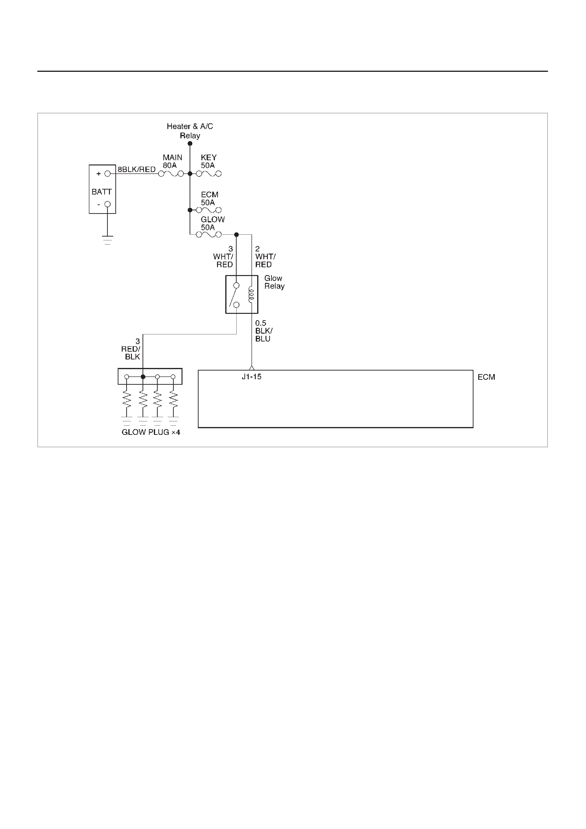
Diagnostic Trouble Code (DTC) P0380 (Flash DTC 66)
Glow Relay Circuit Open/Short
060RW132
Circuit Description
Glow relay circuit receives current through Glow 50A fuse
from the battery. Glow relay is circuited to Glow plug.
Action Taken When the DTC Sets
DThe ECM will store conditions which were present
when the DTC was set as Freeze Frame and in the
Failure Records data.
Conditions for Clearing the MIL/DTC
DDTC P0380 can be cleared by using the Tech 2 “Clear
Info” function or by disconnecting the ECM battery
feed.
Diagnostic Aids
An intermittent may be caused by a poor connection,
rubbed-through wire insulation or a wire broken inside the
insulation. Check for:
DPoor connection – Inspect the ECM harness and
connectors for improper mating, broken locks,
improperly formed or damaged terminals, and poor
terminal-to-wire connection.
DDamaged harness – Inspect the wiring harness for
damage.

DTC P0380 – Glow Relay Circuit Open/Short
Step Action Value(s) Yes No
1 W as the “On-Board Diagnostic (OBD) System Check”
performed? — Go to Step 2 Go to OBD
System Check
2 Attempt to start the engine.
Does the engine start? — Go to Step 3 Go to Step 4
3 1. Review and record Failure Records information.
2. Clear DTC P0380.
3. Start the engine and idle for 1 minute.
4. Observe DTCs.
Is DTC P0380 set? — Go to Step 4 Refer to
Diagnostic Aid
4 Check the glow fuse 50A.
Is the glow fuse 50A damage? — Go to Step 5 Go to Step 6
5 Replace the glow fuse 50A.
Is the action complete? — Verify repair Go to Step 6
6 1. Ignition “OFF.”
2. Check for an open or a short to ground in the Glow
relay circuit between the Glow relay connector
and the ECM harness connector.
3. If a problem is found, repair as necessary.
Was a problem found? Verify repair Go to Step 7
7 Check the connections at the Glow relay and replace
the terminals if necessary.
Did any terminals require replacement? — Verify repair Go to Step 8
8 Replace the Glow relay.
Is the action complete? — Verify repair Go to Step 9
9 Check the connections at the ECM and replace the
terminals if necessary.
Did any terminals require replacement? — Verify repair Go to Step 10
10 Replace the ECM (Refer to the Data Programming in
Case of ECM change).
Is the action complete? — Verify repair —

Diagnostic Trouble Code (DTC) P0381 (Flash DTC 67)
Glow Lamp Circuit Open/Short
060RW136
Circuit Description
Glow Lamp Circuit receives current through Meter 10A
fuse, Glow lamp being circuited to ECM.
Action Taken When the DTC Sets
DThe ECM will store conditions which were present
when the DTC was set as Freeze Frame and in the
Failure Records data.
Conditions for Clearing the MIL/DTC
DDTC P0381 can be cleared by using the Tech 2 “Clear
Info” function or by disconnecting the ECM battery
feed.
Diagnostic Aids
An intermittent may be caused by a poor connection,
rubbed-through wire insulation or a wire broken inside the
insulation. Check for:
DPoor connection – Inspect the ECM harness and
connectors for improper mating, broken locks,
improperly formed or damaged terminals, and poor
terminal-to-wire connection.
DDamaged harness – Inspect the wiring harness for
damage.

DTC P0381 – Glow Lamp Circuit Open/Short
Step Action Value(s) YesNo
1Was the “On-Board Diagnostic (OBD) System Check”
performed? —Go to
Step 2
Go to
OBD
System
Check
21. Review and record Failure Records information.
2. Clear DTC P0381.
3. Observe DTCs.
Is DTC P0381 set? —Go to
Step 3
Refer to
Diagnostic
Aid
31. Ignition “OFF.”
2. Remove the Meter assembly.
3. Check for an open or a short to ground in the Glow
Lamp circuit.
4. If a problem is found, repair as necessary.
(On electric bulb of the Glow Lamp, The Glow Lamp
harness circuit)
Was a problem found? —
Refer to the
Meter in
Electric
section 8 Go to
Step 4
4Check the connections at the ECM and replace the
terminals if necessary.
Did any terminals require replacement? — Verify repair Go to
Step 5
5Replace the ECM (Refer to the Data Programming in
Case of ECM change).
Is the action complete? — Verify repair —

Diagnostic Trouble Code (DTC) P1403 (Flash DTC 32)
EGR EVRV Fault
060RW135
Circuit Description
EGR EVRV Circuit has a common power source in
parallel with EGR, VSV, RPCV, and Intake Throttle Motor.
This may cause multiple DTCs. On such occasion, refer
to “Multiple ECM Information sensor DTCs Set”.
Diagnostic Aids
Check for the following conditions:
DPoor connection or damaged EVRV – Inspect the
wiring harness for damage.
DEnsure EVRV is correctly mounted. See
On-Vehicle
Service
.
Reviewing the Failure Records vehicle mileage since the
diagnostic test last failed may help determine how often
the condition that caused the DTC to be set occurs. This
may assist in diagnosing the condition.
Test Description
Number(s) below refer to the step number(s) on the
Diagnostic Chart
3. A malfunctioning MAP sensor can set an EGR DTC.
The MAP sensor could send a constant signal which
is not low enough to set a low MAP DTC. The
constant signal from the MAP sensor also may not
be high enough to set a high MAP DTC. This step
verifies that the MAP sensor is responding.

DTC P1403 – EGR EVRV Fault
Step Action Value(s) YesNo
1Was the “On-Board Diagnostic (OBD) System Check”
performed? —Go to
Step 2
Go to
OBD
System
Check
2Check the EVRV circuit.
Was the EVR V circuit darmage? —Replace the
EVR V circuit Go to
Step 3
31. Start the engine.
2. Monitor the MAP signal with a scan tool while idling.
3. While idling, jab the accelerator pedal about halfway
down and immediately let the engine return to idle.
Did the MAP value on the scan tool show an immediate
large change? —Go to
Step 5
Go to
Step 4
4Replace the MAP sensor.
Is the action complete? — Verify repair —
51. Inspect the exhaust system for modification of
original installed parts or leaks.
2. If a problem was found, repair exhaust system as
necessary.
Was a condition present that required repair? —Go to
Step 8
Go to
Step 6
61. Remove the EGR valve.
2. Visually and physically inspect the pintle, valve
passages and the adapter for excessive deposits or
any kind of a restriction.
3. If a problem is found, clean or replace EGR system
components as necessary.
Was a condition present that required repair? —Go to
Step 8
Go to
Step 7
71. Inspect the EGR passages for a blockage caused
by excessive deposits or other damage.
2. If a problem is found, correct the condition as
necessary.
Was a condition present that required repair? —Go to
Step 8
Refer to
Diagnostic
Aids
81. Review and record the scan tool Failure Records
data.
2. Clear DTC and monitor the scan tool System Info
Screen while operating the vehicle as specified in
“Diagnostic Aids.”
3. Using a scan tool, monitor “DTC” info for DTC
P1403 until the DTC P1403 test runs.
4. Note the test result.
Does the scan tool indicate DTC P1403 failed this
ignition? —
Go to the last
step
completed in
this
diagnostic
chart Repair
complete
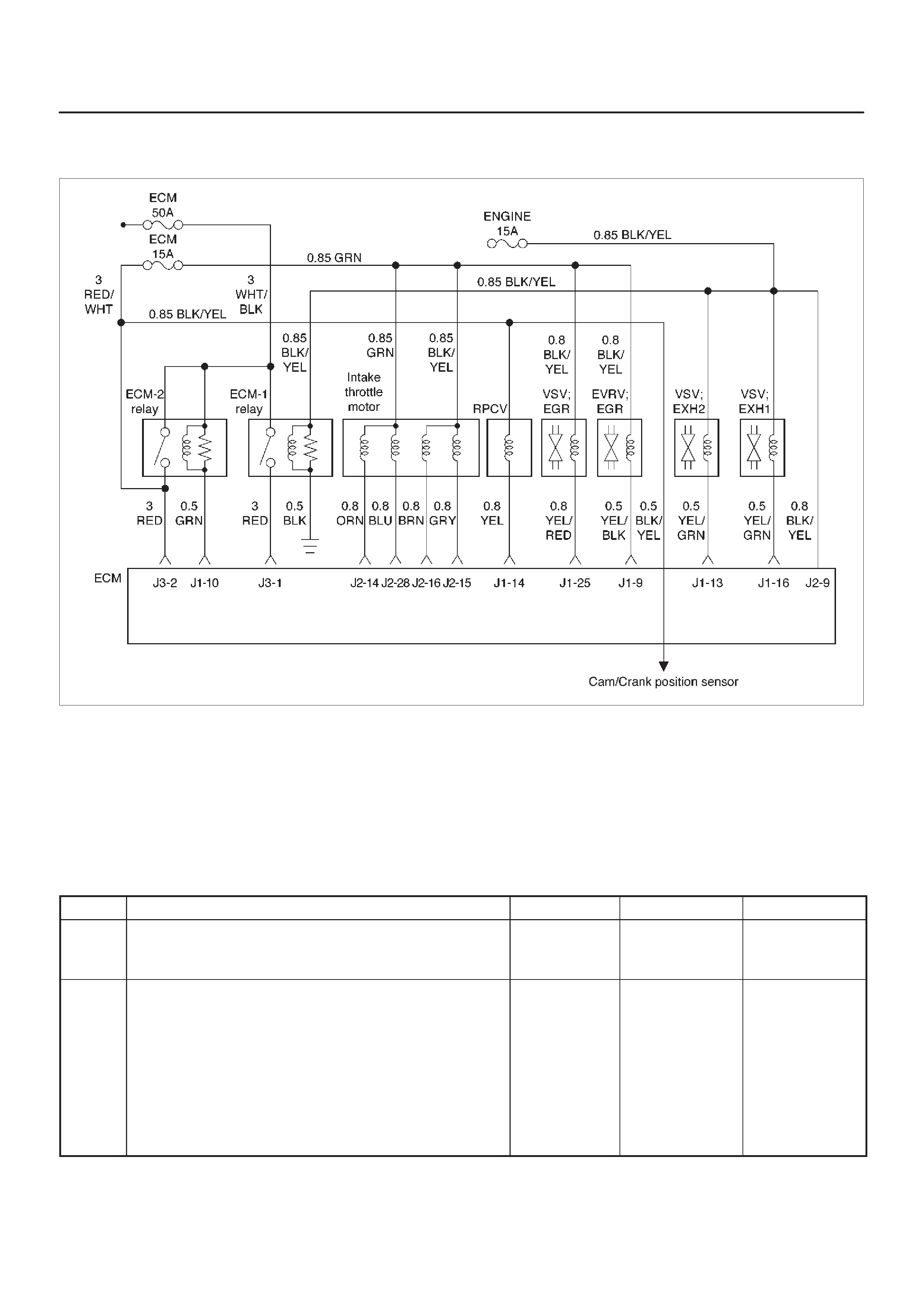
Diagnostic Trouble Code (DTC) P1404 (Flash DTC 31)
EGR VSV Circuit
060RW135
Circuit Description
The Engine control module (ECM) monitors the EGR
valve input to ensure that the valve responds properly to
commands from the ECM, and to detect a fault if VSV is
stuck open. When the VSV is fixing at closed and opening
the ECM will set DTC P1404.
Diagnostic Aids
Check for the following conditions:
DPoor connection or damaged VSV–inspect the wiring
harness for damage.
DTC P1404 – EGR VSV Circuit
Step Action Value(s) YesNo
1Was the “On-Board Diagnostic (OBD) System Check”
performed? —Go to
Step 2
Go to
OBD
System
Check
21. Ignition “ON”, engine “OFF”, review and record
scan tool Failure Records data.
2. Operate the vehicle within Failure Records
conditions as noted.
3. Using a scan tool, monitor “Specific DTC” info for
DTC P1404 until the DTC P1404 test runs. Note the
result.
Does the scan tool indicates DTC P1404 failed this
ignition? — Go to
Step 3
Refer to
Diagnostic
Aids

DTC P1404 – EGR VSV Circuit (Cont'd)
Step NoYesValue(s)Action
3Check the VSV circuit.
Was the VSV circuit open or darmage? —Go to
Step 4
Go to
Step 5
4Repair the opened VSV circuit or VSV.
Is the action complete? — Verify repair —
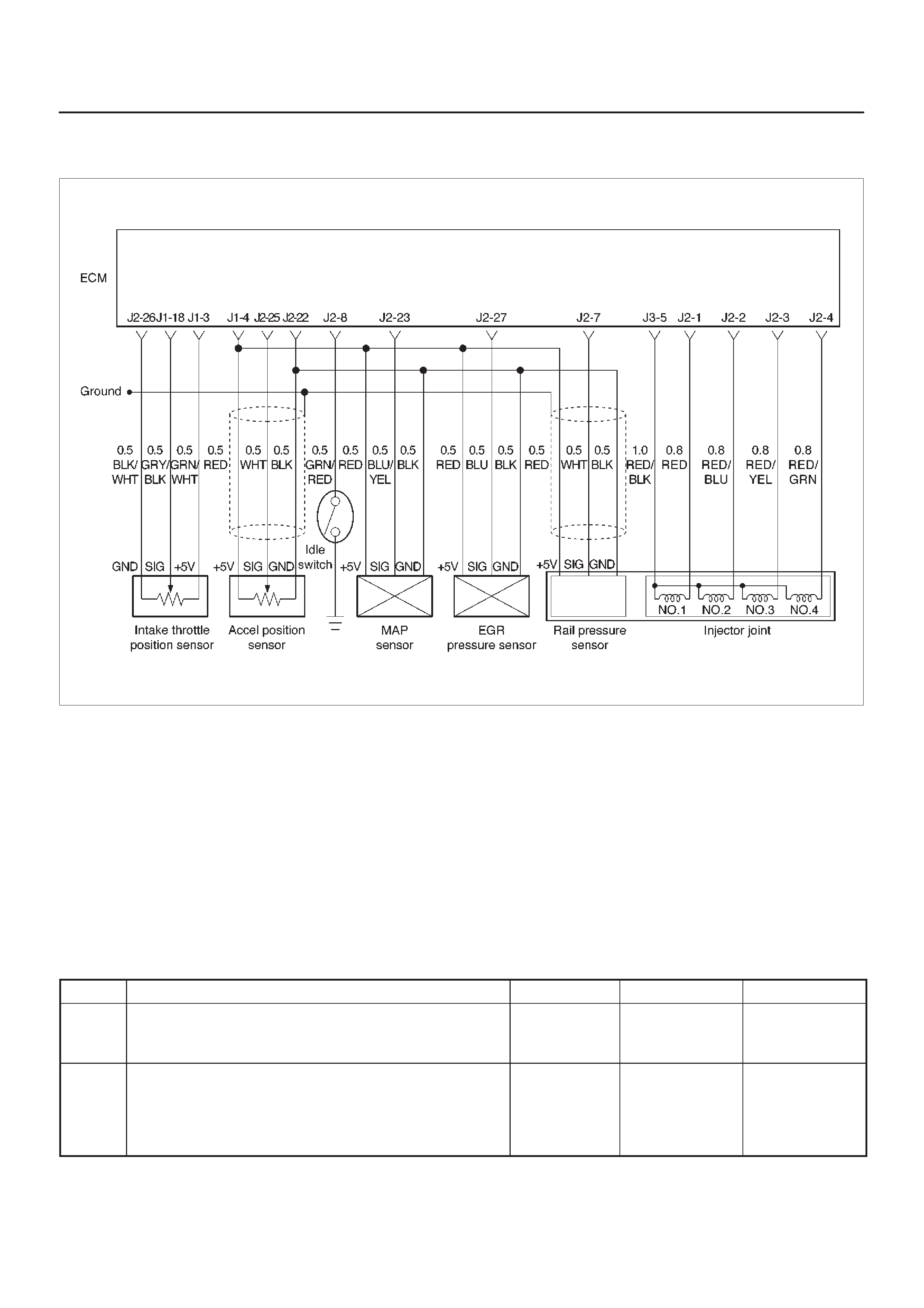
Diagnostic Trouble Code (DTC) P0405 (Flash DTC 26)
EGR Pressure Sensor Low Voltage
060RW134
Action Taken When the DTC Sets
DThe ECM will illuminate the malfunction indicator lamp
(MIL) as soon as failure detected.
DThe ECM will store conditions which were present
when the DTC was set as Freeze Frame and in Failure
Records data.
Conditions for Clearing the MIL/DTC
DDTC P0405 can be cleared by using the scan tool
“Clear Info” function or by disconnecting the ECM
battery feed.
Diagnostic Aids
Check for the following conditions:
DPoor connection or damaged harness – Inspect the
wiring harness for damage.
DTC P0405 – EGR Pressure Sensor Low Voltage
Step Action Value(s) YesNo
1Was the “On-Board Diagnostic (OBD) System Check”
performed? —Go to
Step 2
Go to
OBD
System
Check
2Put the engine into an idling status.
Is the EGR pressure sensor voltage value displayed on
the Tech 2 below the specified value? 0.25 V Go to
Step 3
Refer to
Diagnostic
Aids
and
Symp
tom
Diagnosis

DTC P0405 – EGR Pressure Sensor Low Voltage (Cont'd)
Step NoYesValue(s)Action
31. Turn off the ignition switch.
2. Remove the sensor connector connection.
3. Jumper between harness pins “red” and “blue”
wires.
4. Turn on the ignition switch “ON”.
Is the EGR pressure sensor voltage reading above the
specified value? 4 V Go to
Step 5
Go to
Step 4
41. Turn off the ignition switch.
2. Remove the jumper wire.
3. Connect the relay & solenoid checker
(5-8840-0386-0) to the battery voltage, then check
the EGR pressure sensor signal circuit (blue wire).
4. Turn on the ignition switch.
Is the value displayed on the T ech 2 above the specified
value? 4 V Go to
Step 6
Go to
Step 7
5Check the terminal connection at the EGR pressure
sensor and repair or replace terminal if necessary.
Is the action complete? — Verify repair —
6Repair the 5V power circuit (red) harness or Replace
the ECM (Refer to the Data Programming in Case of
ECM change).
Is the action complete? — Verify repair —
7Repair the signal circuit (blue) harness or Replace the
ECM (Refer to the Data Programming in Case of ECM
change).
Is the action complete? — Verify repair —

Diagnostic Trouble Code (DTC) P1405 (Flash DTC 37)
EGR EVRV Circuit Open/Short
060RW135
Circuit Description
EGR EVRV Circuit has a common power source in
parallel with EGR, VSV, RPCV, and Intake Throttle Motor.
This may cause multiple DTCs. On such occasion, refer
to “Multiple ECM Information Sensor DTCs Set”.
Action Taken When the DTC Sets
DThe ECM will store conditions which were present
when the DTC was set as Freeze Frame and in the
Failure Records data.
Conditions for Clearing the MIL/DTC
DDTC P1405 can be cleared by using the Tech 2 “Clear
Info” function or by disconnecting the ECM battery
feed.
Diagnostic Aids
An intermittent may be caused by a poor connection,
rubbed-through wire insulation or a wire broken inside the
insulation. Check for:
DPoor connection – Inspect the ECM harness and
connectors for improper mating, broken locks,
improperly formed or damaged terminals, and poor
terminal-to-wire connection.
DDamaged harness – Inspect the wiring harness for
damage.

DTC P1405 – EGR EVRV Circuit Open/Short
Step Action Value(s) YesNo
1Was the “On-Board Diagnostic (OBD) System Check”
performed? —Go to
Step 2
Go to
OBD
System
Check
21. Review and record Failure Records information.
2. Clear DTC P1405.
3. Start the engine and idle for 1 minute.
4. Observe DTCs.
Is DTC P1405 set? —Go to
Step 3
Refer to
Diagnostic
Aid
31. Ignition “OFF.”
2. Disconnect the EVRV.
3. Check for an open or a short to ground in the EVRV
circuit between the EVRV connector and the ECM
harness connector.
4. If a problem is found, repair as necessary.
Was a problem found? — Verify repair Go to
Step 4
4Check the connections at the EVRV and replace the
terminals if necessary.
Did any terminals require replacement? — Verify repair Go to
Step 5
5Check the connections at the ECM and replace the
terminals if necessary.
Did any terminals require replacement? — Verify repair Go to
Step 6
6Replace the EVRV.
Is the action complete? — Verify repair Go to
Step 7
7Replace the ECM (Refer to the Data Programming in
Case of ECM change).
Is the action complete? — Verify repair —
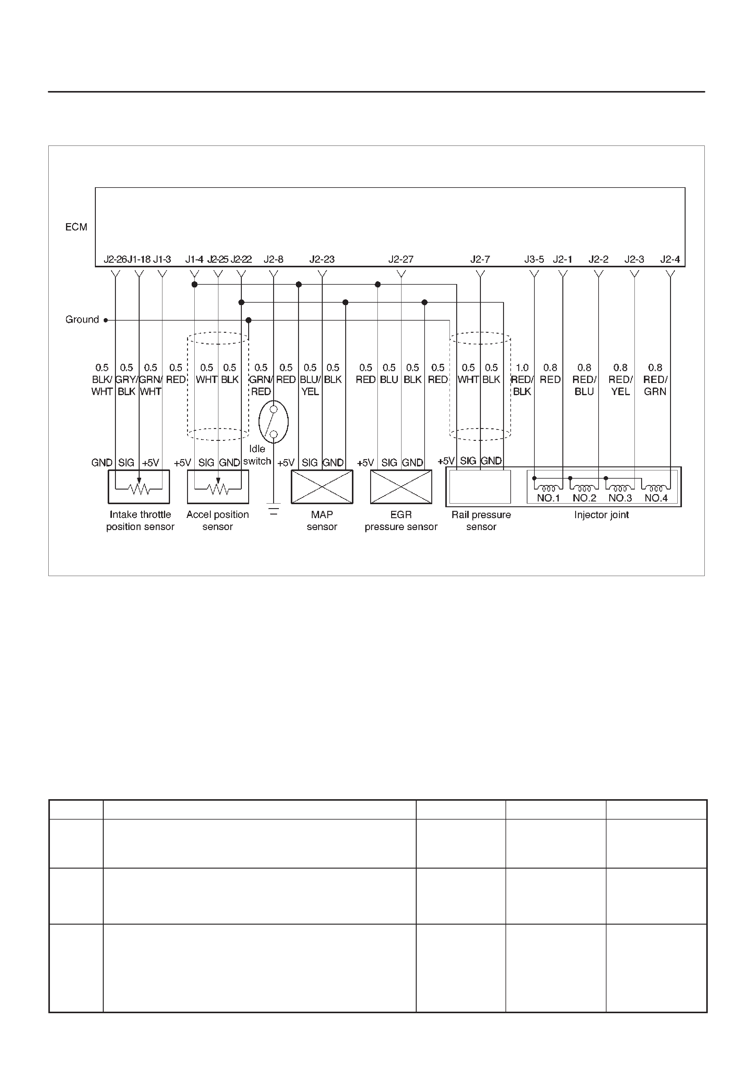
Diagnostic Trouble Code (DTC) P0406 (Flash DTC 26)
EGR Pressure Sensor High Voltage
060RW134
Action Taken When the DTC Sets
DThe ECM will illuminate the malfunction indicator lamp
(MIL) as soon as failure detected.
DThe ECM will store conditions which were present
when the DTC was set as Freeze Frame and in Failure
Records data.
Conditions for Clearing the MIL/DTC
DDTC P0404 can be cleared by using the scan tool
“Clear Info” function or by disconnecting the ECM
battery feed.
Diagnostic Aids
Check for the following conditions:
DPoor connection or damaged harness – Inspect the
wiring harness for damage.
DTC P0406 – EGR Pressure Sensor High Voltage
Step Action Value(s) YesNo
1Was the “On-Board Diagnostic (OBD) System Check”
performed? —Go to
Step 2
Go to
OBD
System
Check
2Put the engine into an idling status.
Is the EGR pressure sensor voltage value displayed on
the Tech 2 above the specified value? 4 V Go to
Step 3
Go to
Step 4
31. Turn off the ignition switch.
2. Remove the sensor connector connection.
3. Turn on the ignition switch “ON”.
Is the EGR pressure sensor voltage value displayed on
the Tech 2 below the specified value? 1 V Go to
Step 5
Go to
Step 6

DTC P0406 – EGR Pressure Sensor High Voltage (Cont'd)
Step NoYesValue(s)Action
4Is the EGR pressure sensor voltage value displayed on
the Tech 2 below the specified value?
1 V Refer to
Chart P0107
Refer to
Diagnostic
Aids
and
Symp
tom
Diagnosis
5Connect the relay and solenoid checker
(5-8840-0386-0) to the battery voltage, then check the
sensor grounding circuit.
Does the checker lamp come on? —Go to
Step 7
Go to
Step 8
6A voltage short circuit occurs in the MAP signal circuit
or this circuit is shorted with the 5V power circuit.
Repair the harness or Replace the ECM (Refer to the
Data Programming in Case of ECM change).
Is the action complete? — Verify repair —
7Replace the EGR pressure sensor hose or the EGR
pressure sensor.
Is the action complete? — Verify repair —
8Repair the harness for open ground circuit.
Is the action complete? — Verify repair —
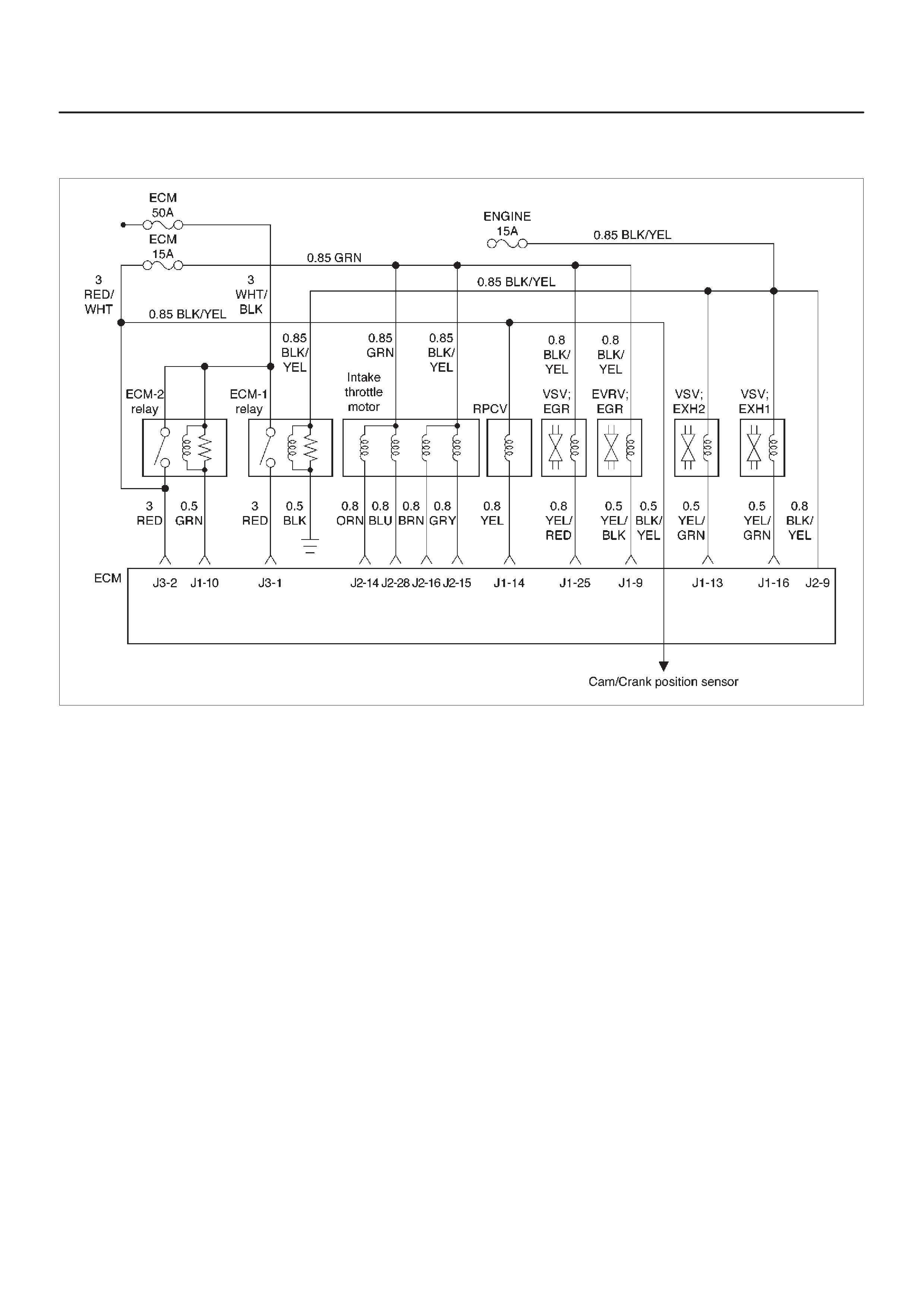
Diagnostic Trouble Code (DTC) P0475 (Flash DTC 71)
EXH #1 VSV Circuit
060RW135
Circuit Description
EXH. #1, #2 VSV Circuit receives current through Engine
15A fuse, #1 and #2 being connected in parallel.
Action Taken When the DTC Sets
DThe ECM will illuminate the malfunction indicator lamp
(MIL) the first time the fault is detected.
DThe ECM will store conditions which were present
when the DTC was set as Freeze Frame and in the
Failure Records data.
Conditions for Clearing the MIL/DTC
DDTC P0475 can be cleared by using the Tech 2 “Clear
Info” function or by disconnecting the ECM battery
feed.
Diagnostic Aids
Check for the following conditions:
DPoor connection at ECM – Inspect harness connectors
for backed-out terminals, improper mating, broken
locks, improperly formed or damaged terminals, and
poor terminal-to-wire connection.
DDamaged harness – Inspect the wiring harness for
damage.

DTC P0475 – EXH #1 VSV Circuit Open/Short
Step Action Value(s) YesNo
1Was the “On-Board Diagnostic (OBD) System Check”
performed? —Go to
Step 2
Go to
OBD
System
Check
21. Ignition “ON,” engine “OFF.” Review and record
Tech 2 Failure Records data.
2. Operate the vehicle within Failure Records
conditions as noted.
3. Using a Tech 2, monitor the “ DTC” info for DTC
P0475.
Does the Tech 2 indicate DTC P0475 failed this
ignition? — Go to
Step 3
Refer to
Diagnostic
Aids
31. Ignition “OFF.”
2. Disconnect the EXH #1 VSV connectors.
3. Check the EXH #1 VSV circuit for a short to ground.
Is the EXH #1 VSV circuit shorted to ground? — Verify repair Go to
Step 4
4Replace the EXH #1 VSV.
Is the action complete? — Verify repair Go to
Step 5
51. Ignition “ON,” engine “OFF.” Review and record
Tech 2 Failure Records data.
2. Operate the vehicle within Failure Records
conditions as noted.
3. Using a Tech 2, monitor the “ DTC” info for DTC
P0475.
Does the Tech 2 indicate DTC P0475 failed this
ignition? — Go to
Step 6
—
6Replace the ECM (Refer to the Data Programming in
Case of ECM change).
Is the action complete? — Verify repair —

Diagnostic Trouble Code (DTC) P1475 (Flash DTC 71)
EXH #2 VSV Circuit Open/Short
060RW135
Circuit Description
EXH. #1, #2 VSV Circuit receives current through Engine
15A fuse, #1 and #2 being connected in parallel.
Action Taken When the DTC Sets
DThe ECM will illuminate the malfunction indicator lamp
(MIL) the first time the fault is detected.
DThe ECM will store conditions which were present
when the DTC was set as Freeze Frame and in the
Failure Records data.
Conditions for Clearing the MIL/DTC
DDTC P1475 can be cleared by using the Tech 2 “Clear
Info” function or by disconnecting the ECM battery
feed.
Diagnostic Aids
Check for the following conditions:
DPoor connection at ECM – Inspect harness connectors
for backed-out terminals, improper mating, broken
locks, improperly formed or damaged terminals, and
poor terminal-to-wire connection.
DDamaged harness – Inspect the wiring harness for
damage.

DTC P1475 – EXH #2 VSV Circuit Open/Short
Step Action Value(s) YesNo
1Was the “On-Board Diagnostic (OBD) System Check”
performed? —Go to
Step 2
Go to
OBD
System
Check
21. Ignition “ON,” engine “OFF.” Review and record
Tech 2 Failure Records data.
2. Operate the vehicle within Failure Records
conditions as noted.
3. Using a Tech 2, monitor the “ DTC” info for DTC
P1475.
Does the Tech 2 indicate DTC P1475 failed this
ignition? — Go to
Step 3
Refer to
Diagnostic
Aids
31. Ignition “OFF.”
2. Disconnect the EXH #2 connectors.
3. Check the EXH #2 circuit for a short to ground.
Is the EXH #2 circuit shorted to ground? — Verify repair Go to
Step 4
4Replace the EXH #2 VSV.
Is the action complete? — Verify repair Go to
Step 5
51. Ignition “ON,” engine “OFF.” Review and record
Tech 2 Failure Records data.
2. Operate the vehicle within Failure Records
conditions as noted.
3. Using a Tech 2, monitor the “ DTC” info for DTC
P1475.
Does the Tech 2 indicate DTC P1475 failed this
ignition? — Go to
Step 6
—
6Replace the ECM (Refer to the Data Programming in
Case of ECM change).
Is the action complete? — Verify repair —
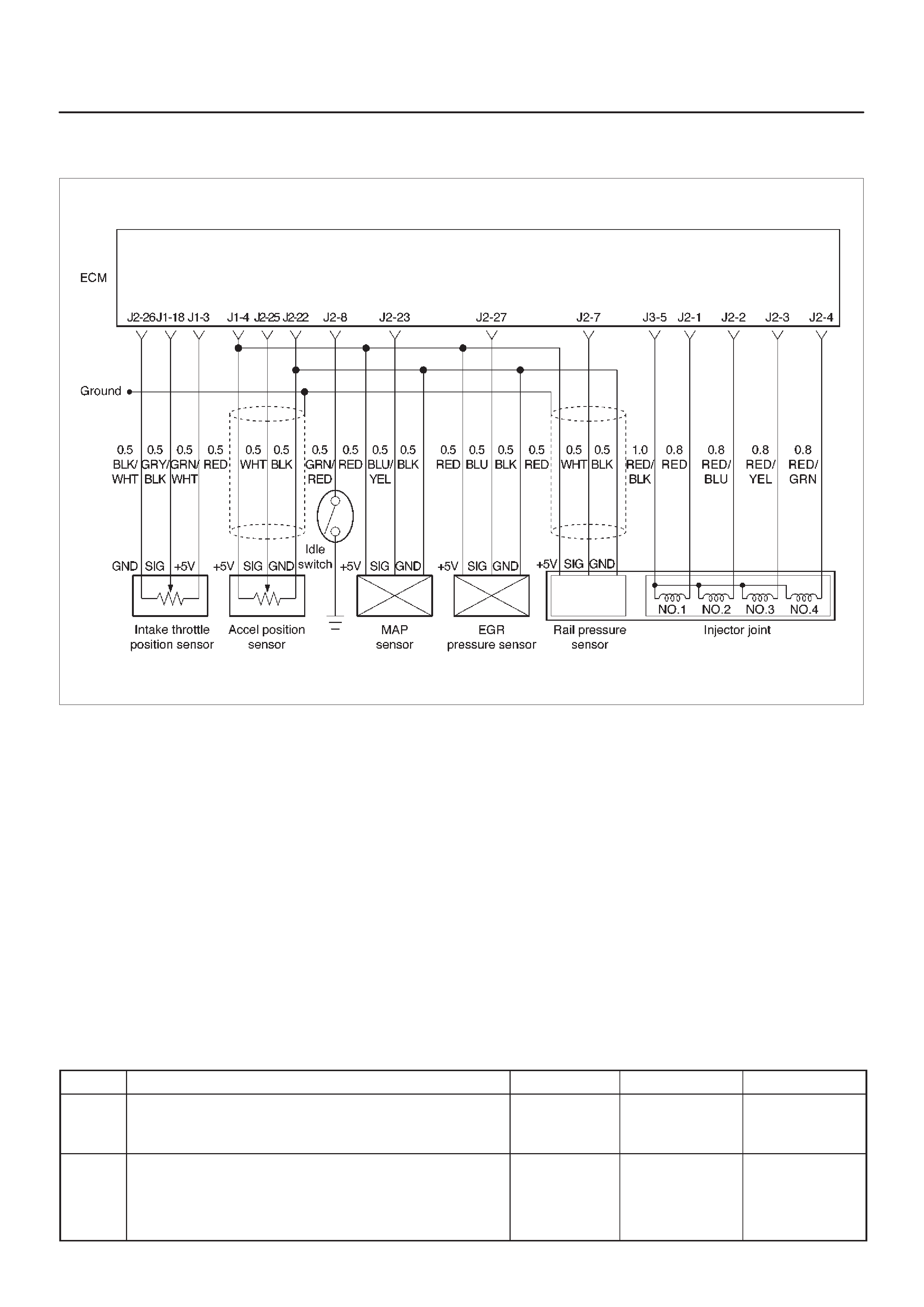
Diagnostic Trouble Code (DTC) P1485 (Flash DTC 74)
ITP (Intake Thorottle Position) Sensor Low Voltage
060RW134
Circuit Description
The intake throttle position (ITP) sensor circuit provides a
voltage signal that changes relative to throttle blade
angle.
Action Taken When the DTC Sets
DThe ECM will illuminate the malfunction indicator lamp
(MIL) the first time the fault is detected.
DThe ECM will store conditions which were present
when the DTC was set as Freeze Frame and in the
Failure Records data.
Conditions for Clearing the MIL/DTC
DDTC P1485 can be cleared by using the Tech 2 “Clear
Info” function or by disconnecting the ECM battery
feed.
Diagnostic Aids
Check for the following conditions:
DPoor connection at ECM – Inspect harness connectors
for backed-out terminals, improper mating, broken
locks, improperly formed or damaged terminals, and
poor terminal-to-wire connection.
DDamaged harness – Inspect the wiring harness for
damage.
If the harness appears to be OK, observe the
throttle position display on the Tech 2 while
moving connectors and wiring harnesses related
to the ITP sensor. A change in the display will
indicate the location of the fault.
If DTC P1485 cannot be duplicated, the information
included in the Failure Records data can be useful in
determining vehicle mileage since the DTC was last set.
DTC P1485 –ITP Sensor Low Voltage
Step Action Value(s) YesNo
1Was the “On-Board Diagnostic (OBD) System Check”
performed? —Go to
Step 2
Go to
OBD
System
Check
21. Ignition “ON,” engine “OFF.”
2. With the throttle closed by the hand, observe the
“ITP Sensor” display on the Tech 2.
Is the “ITP Sensor” below the specified value? 0.22 V Go to
Step 4
Go to
Step 3

DTC P1485 –ITP Sensor Low Voltage (Cont'd)
Step NoYesValue(s)Action
3 1. Ignition “ON,” engine “OFF.”
2. Review and record Tech 2 Failure Records data.
3. Operate the vehicle within Failure Records
conditions as noted.
4. Using a Tech 2, monitor the “DTC” info for DTC
P1485.
Does the Tech 2 indicate DTC P1485 failed? —Go to
Step 4
Refer to
Diagnostic
Aids
4Check the ITP sensor signal circuit for a poor
connection at the ECM and replace the terminal if
necessary.
Did the terminal require replacement? — Verify repair Go to
Step 5
51. Ignition “ON,” engine “OFF.”
2. Review and record Tech 2 Failure Records data.
3. Operate the vehicle within Failure Records
conditions as noted.
4. Using a Tech 2 monitor the “Specific DTC” info for
DTC P1485.
Dose the Tech 2 indicate DTC P1485 failed? —Go to
Step 6
Refer to
Diagnostic
Aids
6Replace the intake throttle.
Is the action complete? — Verify repair Go to
Step 7
7Replace the ECM (Refer to the Data Programming in
Case of ECM change).
Is the action complete? — Verify repair —

Diagnostic Trouble Code (DTC) P1486 (Flash DTC 74)
ITP (Intake Throttle Position) Sensor High Voltage
060RW134
Circuit Description
The intake throttle position (ITP) sensor circuit provides a
voltage signal that changes relative to throttle blade
angle.
Action Taken When the DTC Sets
DThe ECM will illuminate the malfunction indicator lamp
(MIL) the first time the fault is detected.
DThe ECM will store conditions which were present
when the DTC was set as Freeze Frame and in the
Failure Records data.
Conditions for Clearing the MIL/DTC
DDTC P1486 can be cleared by using the Tech 2 “Clear
Info” function or by disconnecting the ECM battery
feed.
Diagnostic Aids
Check for the following conditions:
DPoor connection at ECM – Inspect harness connectors
for backed-out terminals, improper mating, broken
locks, improperly formed or damaged terminals, and
poor terminal-to-wire connection.
DDamaged harness – Inspect the wiring harness for
damage. If the harness appears to be OK, observe the
ITP sensor display on the Tech 2 while moving
connectors and wiring harnesses related to the TP
sensor. A change in the display will indicate the
location of the fault.
DFaulty TP sensor – With the ignition key “ON,” engine
“OFF,” observe the TP sensor display on the Tech 2
while slowly depressing the accelerator to wide open
throttle.
If DTC P1486 cannot be duplicated, the information
included in the Failure Records data can be useful in
determining vehicle mileage since the DTC was last set.

DTC P1486 – ITP Sensor High Voltage
Step Action Value(s) YesNo
1Was the “On-Board Diagnostic (OBD) System Check”
performed? —Go to
Step 2
Go to
OBD
System
Check
21. Ignition “ON,” engine “OFF.”
2. With the throttle closed by the hand, observe the
“ITP Sensor” display on the Tech 2.
Is the “ITP Sensor” above the specified value? 4.88 V Go to
Step 4
Go to
Step 3
31. Ignition “ON,” engine “OFF.”
2. Review and record Tech 2 Failure Records data.
3. Operate the vehicle within Failure Records
conditions as noted.
4. Using a Tech 2, monitor “DTC” info for DTC P1486.
Does the Tech 2 indicate DTC P1486 failed. —Go to
Step 4
Refer to
Diagnostic
Aids
4Check for poor electrical connections at the ITP sensor
and replace terminals if necessary.
Did any terminals require replacement? — Verify repair Go to
Step 5
51. Ignition “ON,” engine “OFF.”
2. Review and record Tech 2 Failure Records data.
3. Operate the vehicle within Failure Records
conditions as noted.
4. Using a Tech 2 monitor the “DTC” info for DTC
P1486.
Dose the Tech 2 indicate DTC P1486 failed. —Go to
Step 6
Refer to
Diagnostic
Aids
6Replace the intake throttle.
Is the action complete? — Verify repair Go to
Step 7
7Replace the ECM (Refer to the Data Programming in
Case of ECM change).
Is the action complete? — Verify repair —

Diagnostic Trouble Code (DTC) P1487 (Flash DTC 73)
Intake Throttle System Circuit Open/Start
060RW134
Circuit Description
The intake throttle position (ITP) sensor circuit provides a
voltage signal that changes relative to throttle blade
angle.
Action Taken When the DTC Sets
DThe ECM will illuminate the malfunction indicator lamp
(MIL) the first time the fault is detected.
DThe ECM will store conditions which were present
when the DTC was set as Freeze Frame and in the
Failure Records data.
Conditions for Clearing the MIL/DTC
DDTC P1487 can be cleared by using the Tech 2 “Clear
Info” function or by disconnecting the ECM battery
feed.
Diagnostic Aids
Check for the following conditions:
DPoor connection at ECM – Inspect harness connectors
for backed-out terminals, improper mating, broken
locks, improperly formed or damaged terminals, and
poor terminal-to-wire connection.
DDamaged harness – Inspect the wiring harness for
damage. If the harness appears to be OK, observe the
throttle position display on the Tech 2 while moving
connectors and wiring harnesses related to the ITP
sensor. A change in the display will indicate the
location of the fault.
If DTC P1487 cannot be duplicated, the information
included in the Failure Records data can be useful in
determining vehicle mileage since the DTC was last set.

DTC P1487 – Intake Throttle System Circuit Open/Short
Step Action Value(s) YesNo
1Was the “On-Board Diagnostic (OBD) System Check”
performed? —Go to
Step 2
Go to
OBD
System
Check
21. Ignition “ON,” engine “OFF.”
2. Review and record Tech 2 Failure Records data.
3. Operate the vehicle within Failure Records
conditions as noted.
4. Using a Tech 2, monitor the “DTC” info for DTC
P1487.
Does the Tech 2 indicate DTC P1487 failed? —Go to
Step 3
Refer to
Diagnostic
Aids
3Check the ITP circuit for a poor connection at the ECM
and ITP and replace the terminal if necessary.
Did the terminal require replacement? — Verify repair Go to
Step 4
41. Ignition “ON,” engine “OFF.”
2. Operate the throttle by the hand.
Is the action complete? — Verify repair Go to
Step 5
5Replace the ITP Assembly.
Is the action complete? — Verify repair Go to
Step 6
6Replace the ECM (Refer to the Data Programming in
Case of ECM change).
Is the action complete? — Verify repair —

Diagnostic Trouble Code (DTC) P1488 (Flash DTC 72)
Intake Throttle Motor Control Circuit Signal Gap
060RW135
Circuit Description
The Intake throttle position (ITP) sensor circuit provides a
voltage signal that changes relative to throttle blade
angle.
Action Taken When the DTC Sets
DThe ECM will store conditions which were present
when the DTC was set as Freeze Frame and in the
Failure Records data.
Conditions for Clearing the MIL/DTC
DDTC P1488 can be cleared by using the Tech 2 “Clear
Info” function or by disconnecting the ECM battery
feed.
Diagnostic Aids
Check for the following conditions:
DPoor connection at ECM – Inspect harness connectors
for backed-out terminals, improper mating, broken
locks, improperly formed or damaged terminals, and
poor terminal-to-wire connection.
DDamaged harness – Inspect the wiring harness for
damage. If the harness appears to be OK, observe the
throttle position display on the Tech 2 while moving
connectors and wiring harnesses related to the ITP
sensor. A change in the display will indicate the
location of the fault.
If DTC P1488 cannot be duplicated, the information
included in the Failure Records data can be useful in
determining vehicle mileage since the DTC was last set.

DTC P1488 – Intake Throttle Motor Control Circuit Signal Gap
Step Action Value(s) YesNo
1Was the “On-Board Diagnostic (OBD) System Check”
performed? —Go to
Step 2
Go to
OBD
System
Check
21. Ignition “ON,” engine “OFF.”
2. With the throttle closed, observe the “ITP Sensor”
display on the Tech 2.
Is the “ITP Sensor” below the specified value? 0.22 V Go to
Step 4
Go to
Step 3
31. Ignition “ON,” engine “OFF.”
2. Review and record Tech 2 Failure Records data.
3. Operate the vehicle within Failure Records
conditions as noted.
4. Using a Tech 2, monitor the “Specific DTC” info for
DTC P1488.
Does the Tech 2 indicate DTC P1488 failed? —Go to
Step 4
Refer to
Diagnostic
Aids
4Check the ITP circuit for a poor connection at the ECM
and replace the terminal if necessary.
Did the terminal require replacement? — Verify repair Go to
Step 5
5Check the Intake throttle motor circuit for a poor
connection and replace the terminal if necessary.
Did the terminal require replacement? — Verify repair Go to
Step 6
6Check the ITP Assembly for a poor connection at the
TP sensor and fasten the ITP Assembly if necessary.
Did the ITP Assembly require repair? — Verify repair Go to
Step 7
7Replace the ECM (Refer to the Data Programming in
Case of ECM change).
Is the action complete? — Verify repair —
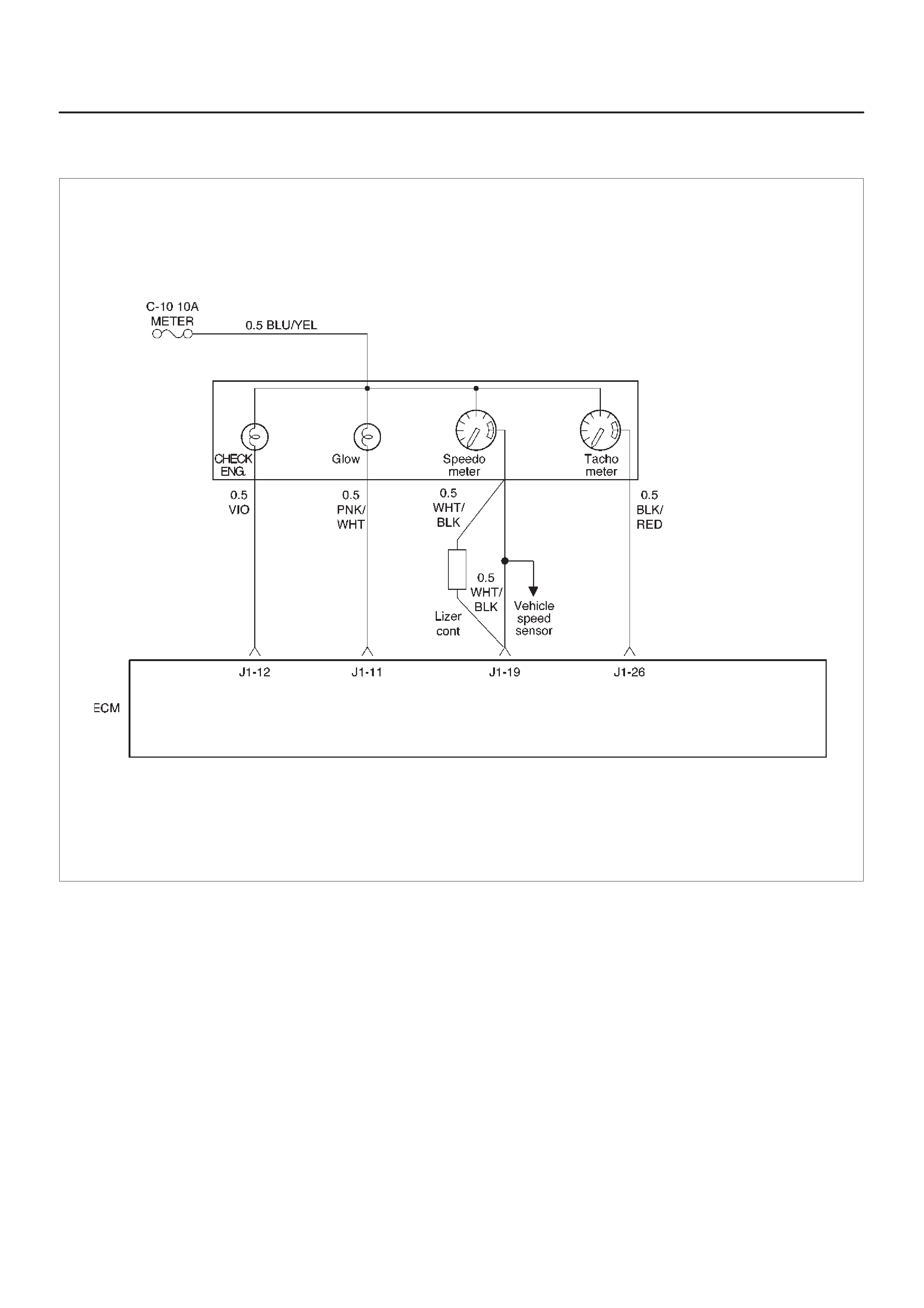
Diagnostic Trouble Code (DTC) P0502 (Flash DTC 24)
VSS (Vehicle Speed Sensor) No Signal
060RW136
Circuit Description
The vehicle speed sensor has a magnet rotated by the
transmission output shaft. Attached to the sensor is a hall
effect circuit the interacts with the magnetic field treated
by the rotating magnet. A 12-volt operating supply for the
speed sensor hall circuit is supplied from the meter fuse.
The VSS pulses to ground the 9-volt signal sent from the
engine control module (ECM) on the reference circuit.
The ECM interprets vehicle speed by the number of
pulses to ground per second on the reference circuit.
Action Taken When the DTC Sets
DThe ECM will illuminate the malfunction indicator lamp
(MIL) the first time the fault is detected.
DThe ECM will store conditions which were present
when the DTC was set as Freeze Frame and in the
Failure Records data.
Conditions for Clearing the MIL/DTC
DDTC P0502 can be cleared by using the Tech 2 “Clear
Info” function or by disconnecting the ECM battery
feed.

Test Description
Number(s) below refer to the step number(s) on the
Diagnostic Chart.
10. To avoid backprobing the VSS and possibly
damaging a seal or terminal, the VSS output can be
tested at the point where the transmission harness
connected to the engine harness. The green 16-way
connector is adjacent to a blue 16-way connector,
and it can be easily accessed by removing the air
cleaner assembly. The green 16-way connector is
separated, and battery voltage is applied to the VSS
through the yellow wire at one corner of the
connector. The VSS output can be monitored with a
DVM connected to the blue wire with a black tracer.
The two wires are next to each other in the 16-way
connector . The test connections are made on the
transmission side of the connector, the side that is
not clipped to the body sheetmetal.
11. The speedometer-to-ECM VSS signal wire is
spliced to a wire leading to the cruise control
module. If a short to ground or voltage is found
between the ECM and speedometer, it could be
located between the splice and the cruise control
module.
DTC P0502 –VSS No Signal
Step Action Value(s) YesNo
1Was the “On-Board Diagnostic (OBD) System Check”
performed? —Go to
Step 2
Go to
OBD
System
Check
2Does the speedometer work? —Go to
Step 10
Go to
Step 3
31. Disconnect the VSS connector.
2. Ignition “ON.”
3. Using a test light to battery +, probe the connector
ground wire.
Did the light illuminate? —Go to
Step 5
Go to
Step 4
4Repair the sensor ground.
Is the action complete? — Verify repair —
51. Ignition “ON,” sensor disconnected.
2. Using a DVM, measure at the VSS connector
between ground and voltage supply.
Was the measurement near the specified value? Battery
voltage Go to
Step 7
Go to
Step 6
6Repair the open or short to ground which may have
blown the meter fuse.
Is the action complete? — Verify repair —
71. Ignition “ON,” VSS disconnected.
2. Using a DVM, measure at the VSS connector
between ground and the blue/black wire from the
speedometer.
Was the measurement near the specified value? 7.5-8 V Go to
Step 9
Go to
Step 8
8Check for an open or short circuit between the
speedometer and the VSS.
Was an open or short circuit located? — Verify repair Go to
Step 9
9Replace the VSS.
Is the action complete? — Verify repair Go to
Step 10
10 Replace the speedometer.
Is the action complete? — Verify repair Go to
Step 11

DTC P0502 –VSS No Signal (Cont'd)
Step NoYesValue(s)Action
11 Check for an open or short between the ECM and the
speedometer.
Was a problem found? — Verify repair Go to
Step 12
12 Replace the ECM (Refer to the Data Programming in
Case of ECM change).
Is the action complete? — Verify repair —

Diagnostic Trouble Code (DTC) P0510 (Flash DTC 75)
Idle SW Malfunction, Open Circuit
060RW134
Circuit Description
The idle switch signal is used by the Engine Control
Module ECM for fuel control.
Action Taken When the DTC Sets
DThe ECM will illuminate the malfunction indicator lamp
(MIL) the first time the fault is detected.
DThe ECM will store conditions which were present
when the DTC was set as Freeze Frame and in the
Failure Records data.
Conditions for Clearing the MIL/DTC
DDTC P0510 can be cleared by using the Tech 2 “Clear
Info” function or by disconnecting the ECM battery
feed.
Diagnostic Aids
Check for the following conditions:
DPoor connection at ECM – Inspect harness connectors
for backed-out terminals, improper mating, broken
locks, improperly formed or damaged terminals, and
poor terminal-to-wire connection.
DDamaged harness – Inspect the wiring harness for
damage. If the harness appears to be OK, observe the
Idle SW display on the T ech 2 while moving connectors
and wiring harnesses related to the Idle SW.
If DTC P0510 cannot be duplicated, the information
included in the Failure Records data can be useful in
determining vehicle mileage since the DTC was last set.

DTC P0510 – Idle SW Malfunction, Open Circuit
Step Action Value(s) YesNo
1Was the “On-Board Diagnostic (OBD) System Check”
performed? —Go to
Step 2
Go to
OBD
System
Check
21. Ignition “ON,” engine “OFF.”
2. Review and record Tech 2 Failure Records data.
3. Operate the vehicle within Failure Records
conditions as noted.
4. Using a Tech 2, monitor the “DTC” info for DTC
P0510.
Does the Tech 2 indicate DTC P0510 failed? —Go to
Step 4
Refer to
Diagnostic
Aids
3Check the Idle SW circuit for a poor connection and
repair the terminal if necessary.
Did the terminal require repair? — Verify repair Go to
Step 4
41. Ignition “ON.”
2. Operate the accel pedal, and check the data list “ON
OFF” on the Tech 2.
Is the data list correct? — Verify repair Go to
Step 5
5Replace the Idle SW.
Is the action complete? — Verify repair —

Diagnostic Trouble Code (DTC) P1510 (Flash DTC 75)
Idle SW Malfunction Short Circuit
060RW134
Circuit Description
The idle switch signal is used by the Engine Control
Module ECM for fuel control.
Action Taken When the DTC Sets
DThe ECM will illuminate the malfunction indicator lamp
(MIL) the first time the fault is detected.
DThe ECM will store conditions which were present
when the DTC was set as Freeze Frame and in the
Failure Records data.
Conditions for Clearing the MIL/DTC
DDTC P1510 can be cleared by using the Tech 2 “Clear
Info” function or by disconnecting the ECM battery
feed.
Diagnostic Aids
Check for the following conditions:
DPoor connection at ECM – Inspect harness connectors
for backed-out terminals, improper mating, broken
locks, improperly formed or damaged terminals, and
poor terminal-to-wire connection.
DDamaged harness – Inspect the wiring harness for
damage. If the harness appears to be OK, observe the
Idle SW display on the T ech 2 while moving connectors
and wiring harnesses related to the Idle SW.
If DTC P0122 cannot be duplicated, the information
included in the Failure Records data can be useful in
determining vehicle mileage since the DTC was last set.

DTC P1510 – Idle SW Malfunction, Short Circuit
Step Action Value(s) YesNo
1Was the “On-Board Diagnostic (OBD) System Check”
performed? —Go to
Step 2
Go to
OBD
System
Check
21. Ignition “ON,” engine “OFF.”
2. Review and record Tech 2 Failure Records data.
3. Operate the vehicle within Failure Records
conditions as noted.
4. Using a Tech 2, monitor the “DTC” info for DTC
P1510.
Does the Tech 2 indicate DTC P1510 failed? —Go to
Step 4
Refer to
Diagnostic
Aids
3Check the Idle SW circuit for a poor connection and
repair the terminal if necessary.
Did the terminal require repair? — Verify repair Go to
Step 4
41. Ignition “ON.”
2. Operate the accel pedal, and check the data list “ON
OFF” on the Tech 2.
Is the data list correct? — Verify repair Go to
Step 5
5Replace the Idle SW.
Is the action complete? — Verify repair —

Diagnostic Trouble Code (DTC) P0562 (Flash DTC 35)
System Voltage Too Low
Circuit Description
The engine control module (ECM) monitors the system
voltage on the ignition feed terminals to the ECM. A
system voltage DTC will set whenever the voltage is
above a calibrated value.
Action Taken When the DTC Sets
DThe ECM will not illuminate the malfunction indicator
lamp (MIL).
DThe ECM will store as Failure Records only conditions
which were present when the DTC was set. This
information will not be stored as Freeze Frame data.
Conditions for Clearing the MIL/DTC
DDTC P0563 can be cleared by using the Tech 2 “Clear
Info” function or by disconnecting the ECM battery
feed.
Diagnostic Aids
If the DTC sets when an accessory is operated, check for
a poor connection or defective accessory.
DTC P0562 – System Voltage Too Low
Step Action Value(s) YesNo
1Was the “On-Board Diagnostic (OBD) System Check”
performed? —Go to
Step 2
Go to
OBD
System
Check
2Using a DVM, measure the battery voltage at the
battery.
Is the battery voltage greater than the specified value? 11.5 V Go to
Step 3
Charge
battery, then
go to
Step 3
31. Install a Tech 2.
2. Select “Ignition Volts” on the Tech 2.
3. Start the engine and raise the engine speed to the
specified value.
4. Load the electrical system by turning on the
headlights, high blower, etc.
Is the ignition voltage approximately equal to the
specified value? 2000 RPM
12.8-14.1 V Go to
Step 4
Go to
Starting/
Charging
41. Ignition “OFF.”
2. Disconnect the ECM connector at the ECM.
3. Using a DVM, measure the battery voltage at the
ECM connector.
Is it approximately equal to battery voltage? —
Check for
excessive
current draw
with ignition
“OFF,” engine
“OFF.” Go to
Step 5
51. Check for faulty connections at the ECM harness
terminals.
2. Repair as necessary.
Was a repair necessary? — Verify repair Go to
Step 6
6Check for an open battery feed circuit to the ECM.
Is the action complete? — Verify repair Go to
Step 7
7Replace the ECM (Refer to the Data Programming in
Case of ECM change).
Is the action complete? — Verify repair —

Diagnostic Trouble Code (DTC) P1562 (Flash DTC 35)
System Voltage Too Low at Cranking
Circuit Description
The engine control module (ECM) monitors the system
voltage on the ignition feed terminals to the ECM. A
system voltage DTC will set whenever the voltage is
above a calibrated value.
Action Taken When the DTC Sets
DThe ECM will illuminate the malfunction indicator lamp
(MIL) at the first time of the fault is detected.
Conditions for Clearing the MIL/DTC
DDTC P0563 can be cleared by using the Tech 2 “Clear
Info” function or by disconnecting the ECM battery
feed.
Diagnostic Aids
If the DTC sets when an accessory is operated, check for
a poor connection or defective accessory.
DTC P1562 – System Voltage Too Low at Cranking
Step Action Value(s) YesNo
1Was the “On-Board Diagnostic (OBD) System Check”
performed? —Go to
Step 2
Go to
OBD
System
Check
2Using a DVM, measure the battery voltage at the
battery.
Is the battery voltage less than the specified value? 11.5 V Go to
Step 3
Go to
Step 4
31. Charge the battery and clean the battery terminals.
2. Clean the battery ground cable connection if
corrosion is indicated.
Is the battery voltage less than the specified value? 11.5 V Replace
battery Go to
Step 4
41. Turn “OFF” all the accessories.
2. Install a Tech 2.
3. Select the ignition voltage parameter on the Tech 2.
4. Start the engine and raise the engine RPM to the
specified value.
Is the voltage more than 2.5 volts greater than the
measurement taken in step 2 or 3? 2000 RPM
Go to
Starting/Char
ging
Go to
Step 5
5Replace the ECM (Refer to the Data Programming in
Case of ECM change).
Is the action complete? — Verify repair —

Diagnostic Trouble Code (DTC) P1587 (Flash DTC 25)
Brake SW Malfunction
060RW130
Circuit Description
Brake Stop Lamp SW Circuit receives through Stop Lamp
10A fuse from the battery.
Action Taken When the DTC Sets
DThe ECM will store conditions which were present
when the DTC was set as Freeze Frame and in the
Failure Records data.
Conditions for Clearing the MIL/DTC
DDTC P1587 can be cleared by using the Tech 2 “Clear
Info” function or by disconnecting the ECM battery
feed.
Diagnostic Aids
Check for the following conditions:
DPoor connection at ECM – Inspect harness connectors
for backed-out terminals, improper mating, broken
locks, improperly formed or damaged terminals, and
poor terminal-to-wire connection.
DDamaged harness – Inspect the wiring harness for
damage. If the harness appears to be OK, observe the
Brake SW display on the Tech 2 while moving
connectors and wiring harnesses related to the Brake
SW. A change in the display will indicate the location
of the fault.
If DTC P1587 cannot be duplicated, the information
included in the Failure Records data can be useful in
determining vehicle mileage since the DTC was last set.

DTC P1587 – Brake SW Malfunction
Step Action Value(s) YesNo
1Was the “On-Board Diagnostic (OBD) System Check”
performed? —Go to
Step 2
Go to
OBD
System
Check
21. Ignition “ON,” engine “OFF.”
2. Review and record Tech 2 Failure Records data.
3. Operate the vehicle within Failure Records
conditions as noted.
4. Using a Tech 2, monitor the “DTC” info for DTC
P1587.
Does the Tech 2 indicate DTC P1587 failed? —Go to
Step 3
Refer to
Diagnostic
Aids
3Check the Brake SW circuit for a poor connection and
replace the terminal if necessary.
Did the terminal require replacement? — Verify repair Go to
Step 4
4Replace the Brake SW.
Is the action complete? — Verify repair —
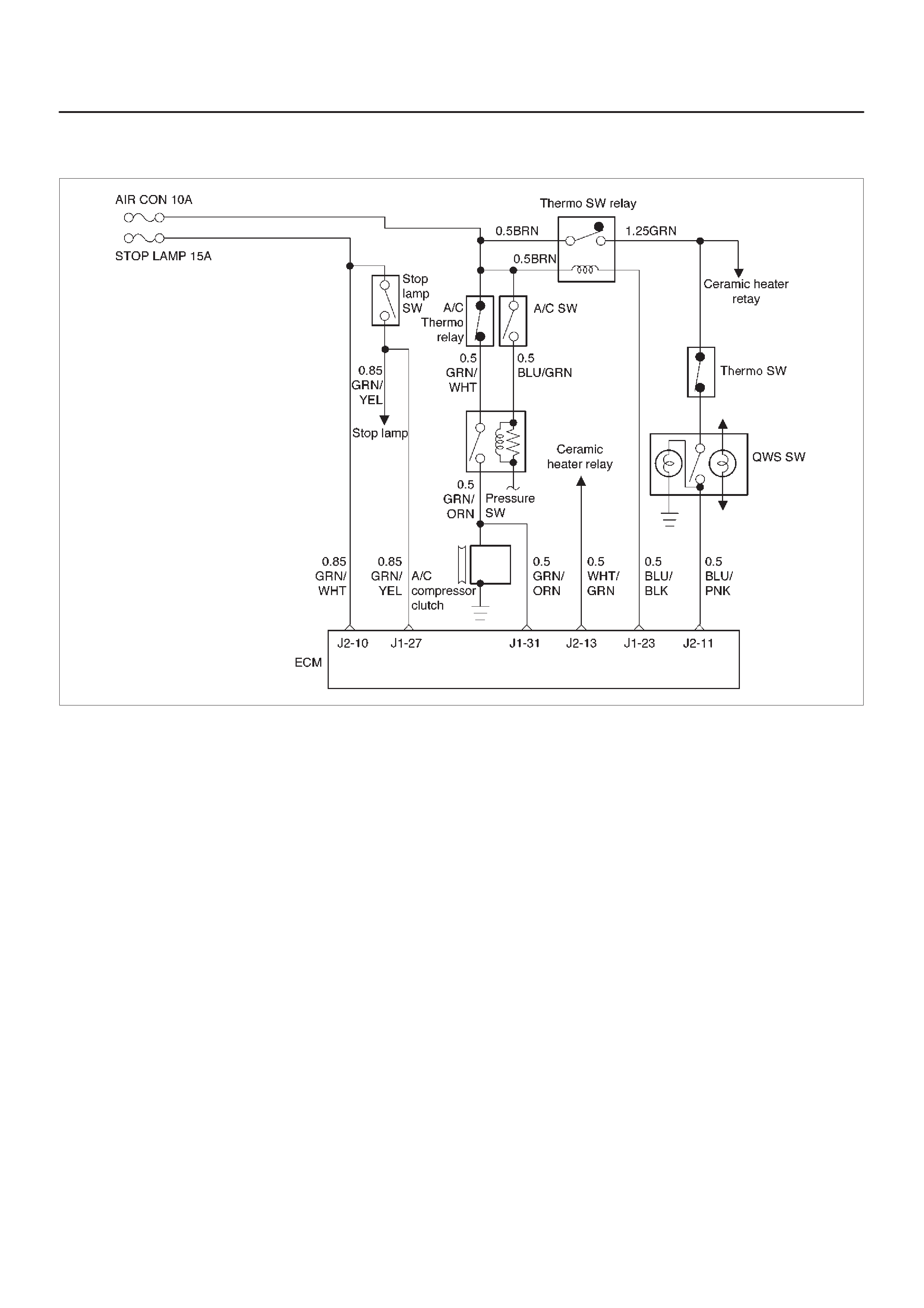
Diagnostic Trouble Code (DTC) P1588 (Flash DTC 25)
Brake SW Malfunction
060RW130
Circuit Description
Brake Stop Lamp SW Circuit receives through Stop Lamp
10A fuse from the battery.
Action Taken When the DTC Sets
DThe ECM will illuminate the malfunction indicator lamp
(MIL) the first time the fault is detected.
DThe ECM will store conditions which were present
when the DTC was set as Freeze Frame and in the
Failure Records data.
Conditions for Clearing the MIL/DTC
DDTC P1588 can be cleared by using the Tech 2 “Clear
Info” function or by disconnecting the ECM battery
feed.
Diagnostic Aids
Check for the following conditions:
DPoor connection at ECM – Inspect harness connectors
for backed-out terminals, improper mating, broken
locks, improperly formed or damaged terminals, and
poor terminal-to-wire connection.
DDamaged harness – Inspect the wiring harness for
damage. If the harness appears to be OK, observe the
Brake SW display on the Tech 2 while moving
connectors and wiring harnesses related to the Brake
SW. A change in the display will indicate the location
of the fault.
If DTC P1588 cannot be duplicated, the information
included in the Failure Records data can be useful in
determining vehicle mileage since the DTC was last set.

DTC P1588 – Brake SW Malfunction
Step Action Value(s) YesNo
1Was the “On-Board Diagnostic (OBD) System Check”
performed? —Go to
Step 2
Go to
OBD
System
Check
21. Ignition “ON,” engine “OFF.”
2. Review and record Tech 2 Failure Records data.
3. Operate the vehicle within Failure Records
conditions as noted.
4. Using a Tech 2, monitor the “DTC” info for DTC
P1588.
Does the Tech 2 indicate DTC P1588 failed? —Go to
Step 3
Refer to
Diagnostic
Aids
3Check the Brake SW circuit for a poor connection and
replace the terminal if necessary.
Did the terminal require replacement? — Verify repair Go to
Step 4
4Replace the Brake SW.
Is the action complete? — Verify repair —

Diagnostic Trouble Code (DTC) P0601 (Flash DTC 55)
ECM Checksum Error
Action Taken When the DTC Sets
DThe ECM will not illuminate the malfunction indicator
lamp (MIL).
DThe ECM will store conditions which were present
when the DTC was set in the Failure Records data only.
Conditions for Clearing the MIL/DTC
DDTC P0601 can be cleared by using the Tech 2 “Clear
Info” function or by disconnecting the ECM battery
feed.
Diagnostic Aids
DDTC P0601 indicates that the contents of the
EEPROM have changed since the ECM was
programmed. The only possible repair is ECM
replacement. Remember to program the replacement
ECM with the correct software and calibration for the
vehicle.
DTC P0601 – ECM Checksum Error
Step Action Value(s) YesNo
1Was the “On-Board Diagnostic (OBD) System Check”
performed? —Go to
Step 2
Go to
OBD
System
Check
2Replace the ECM (Refer to the Data Programming in
Case of ECM change).
Is the action complete? — Verify repair —
Diagnostic Trouble Code (DTC) P1626 - No Response From Immobiliser
4JX1 ICU Circuit.CDR
Circuit Description
The ECM decides whether that is an abnomality in the
Immobiliser control system. DTC P1626 or are recorded
by the ECM when there is no response from
Immobiliser.
Condition for Setting the DTC
• No signal from Immobizer Control Unit to ECM
Acti on Taken When the DTC sets
• Rapid flashing of the MIL (“CHECK ENGINE” lamp).
• The Engine does not start.
Condition for Clearing the MIL/DTC
• Clear DTC information with TECH 2. Refer to
Section 0C TECH 2 Diagnosis
Diagnostic Aids
Check for the following conditions:
• Poor connection at ECM and ImmobiliserInspect
harness connectors for backed out terminals,
improper mating, broken locks, improperly formed or
damaged terminals, and poor terminal to wire
connection.
• Damaged harness-Inspect the wiring harness for
damage, If the harness appears to be OK, disconnect
the ECM and Immobiliser, turn the ignition “ON" and
observe a voltmeter connected to the suspect driver
circuit at the ECM and Immobiliser harness connector
while moving connectors and wiring harnesses
relates to the MIL. A change in voltage will indicate
the location of the fault.
Immobiliser
Relay
Engine
Control
Module
Immobiliser
Control
Unit
Battery +ve
(Fuse C16)
Switched 12V
(Fuse C8)
Ground
Vehicle S peed
Signal
“Check Engine”
Lamp
DLC
DIAGNOSTIC
CONNECTION
DLC PIN 7
Antenna
Coil
0.5 YELLOW
0.5 RED/WHITE
0.5 LIGHT GREEN/WHITE
0.85 BLACK/YEL LOW
0.5 YELLOW
0.5 WHITE/BLAC K
0.5 GREEN/YELLOW
0.5 BLUE
0.5 BLACK
0.5 BLACK
3
9
7
1
5
4
810
6
2J1-12
J1-19
7
3
Ignition
Switch

DTC P1626-No Response From Immobiliser
Step Action Value(s) Yes No
1 Was the “On-Boa rd Diagnostic (OBD) system Check"
performed? — Go to Step 2 Go to OBD
system check
2 U sing the Te ch2 sy stem sele ction me nu, select ‘B ody
- Immobiliser - DTC’ function.
Does the Tech2 display B**** appear?
—
Refer to
Section 11
“Engine
Immobiliser
System" Go to Step 3
3 Using the Tech2 system selection menu, select
‘Powertrain - DTC’ function.
Does the Tech2 display a DTC P1626 as
“PRESENT”?
— Go to Step 4
Refer to
Diagnostic Aids
if DTC P1626 is
displayed as
“NOT
PRESENT”
4 Check the ECM and ICU harness and connectors for:
1. Backed out terminals, improper mating, broken
locks, improperly formed or damaged terminals,
and poor terminal to wire connection.
2. Damaged ha rn es s - Ins pec t the wirin g harne ss for
damage.
If a problem found, repair as necessary.
Was a problem found? — Verify repair Go to Step 5
5 With a DMM, check for an open circuit or a short to
voltage circuit between ECM pin J1-19 and ICU pin 6
(white/black wire).
If a problem found, repair as necessary.
Was a problem found? — Verify repair Go to Step 6
6 Replace the ECM.
Important: The replacement ECM must be
programmed. Refer to Section 0C-1 - Service
Programming System.
Important: Refer to Section 11 - Engine Immobiliser
System for the Immobiliser Programming procedure.
Important: Ensure the latest software program is
downloaded to the ECM.
Is the action complete? — Verify repair —
Diagnostic Trouble Code (DTC) P1631 - Received Response Was Not Correct
060RA00003
Circuit Description
The ECM decides whether that is an abnomality in the
Immobiliser control system. A DTC P1631 is recorded
by the ECM when received response was not correct.
Condition for Setting the DTC
• Received response was not correct.
Ac ti on Taken Wh en th e DTC Sets
• Rapid flashing of the MIL (“CHECK ENGINE” lamp).
• The Engine does not start.
Condition for Clearing the MIL/DTC
• Clear DTC information with TECH 2. Refer to
Section 0C TECH 2 Diagnosis
Diagnostic Aids
Check for the following conditions:
• Poor connection at ECM and Immobiliser - Inspect
harness connectors for backed out terminals,
improper mating, broken locks, improp erly formed or
damaged terminals, and poor terminal to wire
connection.
• Damaged harness - Inspect the wiring harness for
damage, If the harness appears to be OK, disconnect
the ECM and Immobiliser, turn the ignition “ON" and
observe a voltmeter connected to the suspect driver
circuit at the ECM and Immobiliser harness connector
while moving connectors and wiring harnesses
relates to the MIL. A change in voltage will indicate
the location of the fault.
Immobiliser
Relay
Engine
Control
Module
Immobiliser
Control
Unit
Battery +ve
(Fuse C16)
Switched 12V
(Fuse C8)
Ground
Vehicle S peed
Signal
“Check Engine”
Lamp
DLC
DIAGNOSTIC
CONNECTION
DLC PIN 7
Antenna
Coil
0.5 YELLOW
0.5 RED/WHITE
0.5 LIGHT GREEN/WHITE
0.85 BLACK/YEL LOW
0.5 YELLOW
0.5 WHITE/BLAC K
0.5 GREEN/YELLOW
0.5 BLUE
0.5 BLACK
0.5 BLACK
3
9
7
1
5
4
810
6
2J1-12
J1-19
7
3
Ignition
Switch

DTC P1631 - Received Response Was Not Correct
Step Action Value(s) Yes No
1 Was the “On-Boa rd Diagnostic (OBD) system Check"
performed? — Go to Step 2 Go to OBD
system check
2 U sing the Te ch2 sy stem sele ction me nu, select ‘B ody
- Immobiliser - DTC’ function.
Does the Tech2 display B**** appear?
—
Refer to
Section 11
“Engine
Immobiliser
System" Go to Step 3
3 Using the Tech2 system selection menu, select
‘Powertrain - DTC’ function.
Does the Tech2 display a DTC P1631 as
“PRESENT”?
— Go to Step 4
Refer to
Diagnostic Aids
if DTC P1631 is
displayed as
“NOT
PRESENT”
4 Check the ECM and ICU harness and connectors for:
1. Backed out terminals, improper mating, broken
locks, improperly formed or damaged terminals,
and poor terminal to wire connection.
2. Damaged ha rn es s - Ins pec t the wirin g harne ss for
damage.
If a problem found, repair as necessary.
Was a problem found? Verify repair Go to Step 5
5 Replace the ECM.
Important: The replacement ECM must be
programmed. Refer to Section 0C-1 - Service
Programming System.
Important: Refer to Section 11 - Engine Immobiliser
System for the Immobiliser Programming procedure.
Important: Ensure the latest software program is
downloaded to the ECM.
Is the action complete? — Verify repair —
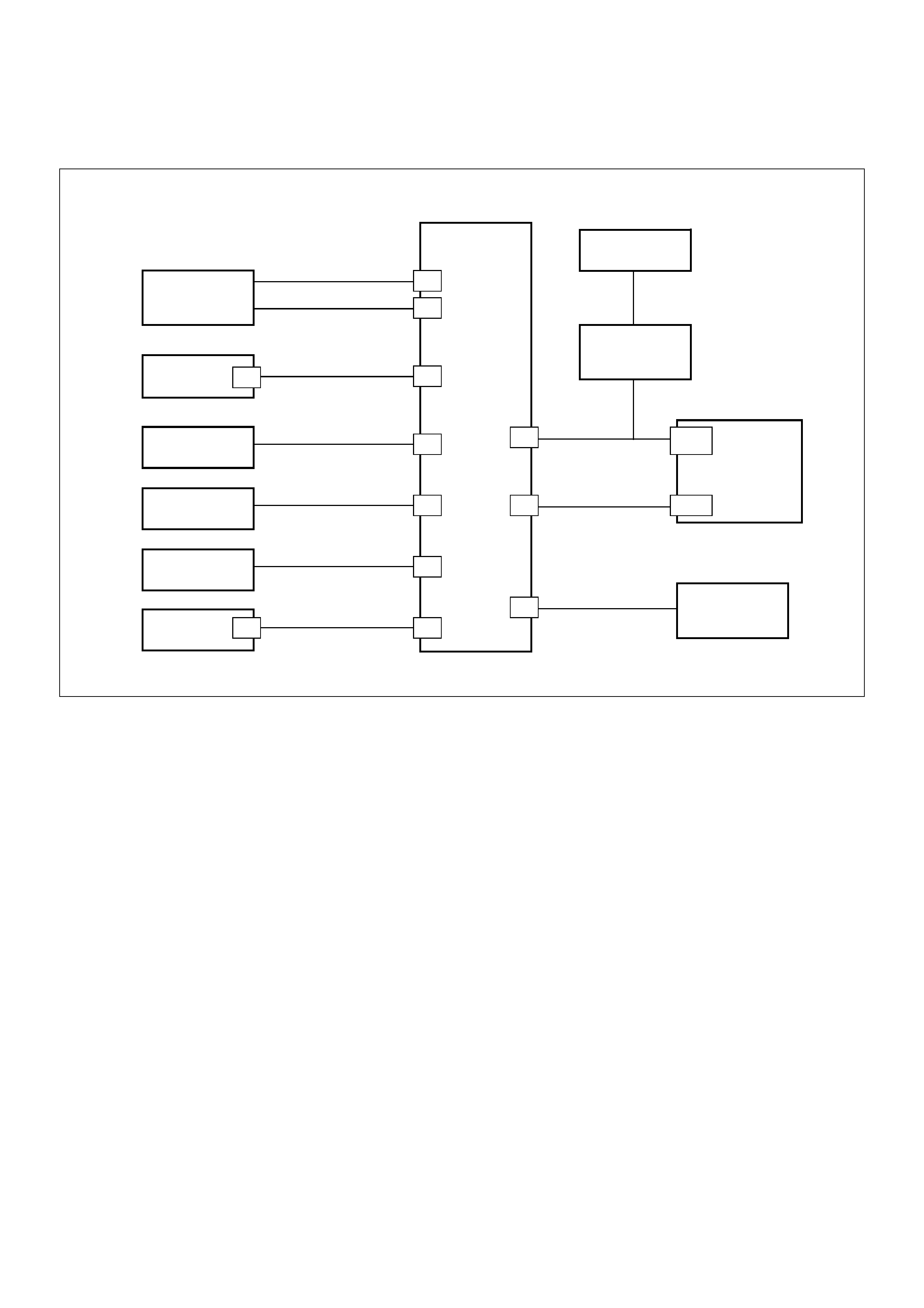
Diagnostic Trouble Code (DTC) P1648 - Received Incorrect Security Code
060RA00003
Circuit Description
The ECM decides whether that is an abnomality in the
Immobiliser control system. A DTC P1648 is recorded
by the ECM when it receives an incorrect security code.
Condition for Setting the DTC
• Received security code is incorrect.
Ac ti on Taken Wh en th e DTC Sets
• Rapid flashing of the MIL (“CHECK ENGINE” lamp).
• The Engine does not start.
Condition for Clearing the MIL/DTC
• Clear DTC information with TECH 2. Refer to
Section 0C TECH 2 Diagnosis
Diagnostic Aids
Check for the following conditions:
• Poor connection at ECM and Immobiliser - Inspect
harness connectors for backed out terminals,
improper mating, broken locks, improp erly formed or
damaged terminals, and poor terminal to wire
connection.
• Damaged harness - Inspect the wiring harness for
damage, If the harness appears to be OK, disconnect
the ECM and Immobiliser, turn the ignition “ON" and
observe a voltmeter connected to the suspect driver
circuit at the ECM and Immobiliser harness connector
while moving connectors and wiring harnesses
relates to the MIL. A change in voltage will indicate
the location of the fault.
Immobiliser
Relay
Engine
Control
Module
Immobiliser
Control
Unit
Battery +ve
(Fuse C16)
Switched 12V
(Fuse C8)
Ground
Vehicle S peed
Signal
“Check Engine”
Lamp
DLC
DIAGNOSTIC
CONNECTION
DLC PIN 7
Antenna
Coil
0.5 YELLOW
0.5 RED/WHITE
0.5 LIGHT GREEN/WHITE
0.85 BLACK/YEL LOW
0.5 YELLOW
0.5 WHITE/BLAC K
0.5 GREEN/YELLOW
0.5 BLUE
0.5 BLACK
0.5 BLACK
3
9
7
1
5
4
810
6
2J1-12
J1-19
7
3
Ignition
Switch

DTC P1648 - Received Incorrect Security Code
Step Action Value(s) Yes No
1 Was the “On-Board Diagnostic (OBD) system Check"
performed? — Go to Step 2 Go to OBD
system check
2 U sing the Te ch2 sy stem selec tion menu, s elect ‘B ody
- Immobiliser - DTC’ function.
Does the Tech2 display B**** appear?
—
Refer to
Section 11
“Engine
Immobiliser
System" Go to Step 3
3 Using the Tech2 system selection menu, select
‘Powertrain - DTC’ function.
Does the Tech2 display a DTC P1648 as
“PRESENT”?
— Go to Step 4
Refer to
Diagnostic Aids
if DTC P1648 is
displayed as
“NOT
PRESENT”
4 Check the ECM and ICU harness and connectors for:
1. Backed out terminals, improper mating, broken
locks, improperly formed or damaged terminals,
and poor terminal to wire connection.
2. Damaged ha rn es s - Ins pec t the wirin g harne ss for
damage.
If a problem found, repair as necessary.
Was a problem found? Verify repair Go to Step 5
5 Recheck the security code.
Is the action complete? — Verify repair —
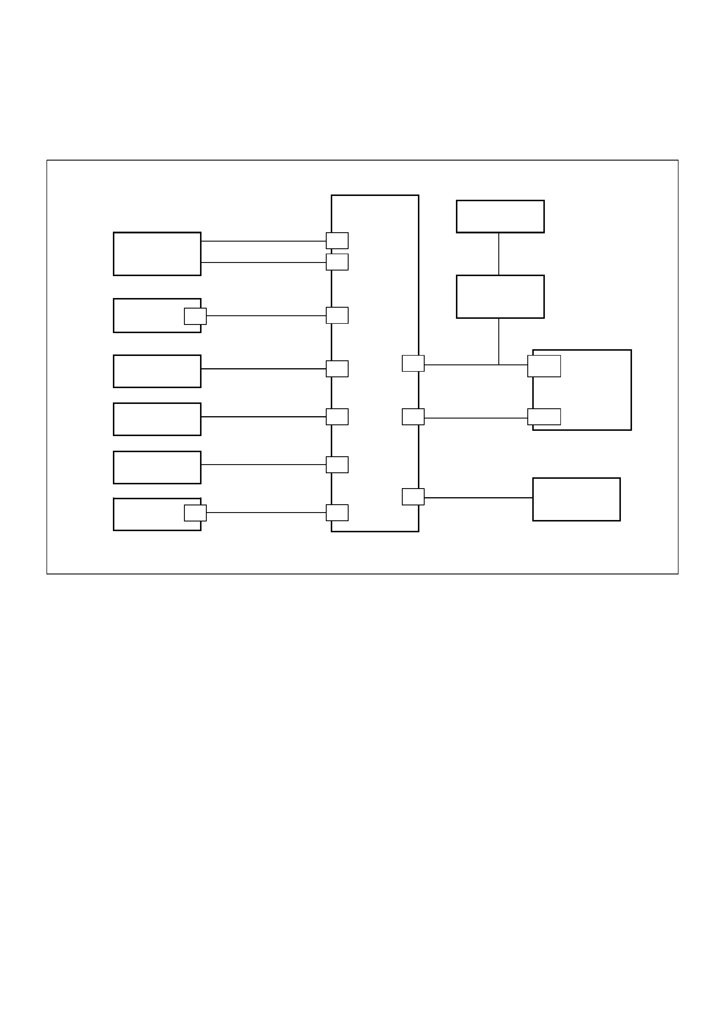
Diagnostic Trouble code (DTC) P1649 - Security Code & Security Key Not
Programmed
060RA00003
Circuit Description
The ECM decides whether that is an abnomality in the
Immobiliser control system. DTC P1649 are recorded
by the ECM when security code & secret key not
programmed.
Condition for Setting the DTC
• Security code & secret key not programmed.
Ac ti on Taken Wh en th e DTC Sets
• Rapid flashing of the MIL (“CHECK ENGINE” lamp).
• The Engine does not start.
In case repla ce ment ECM/ECM, Acti on
Taken When the DTC Sets
• Rapid flashing of the MIL (“CHECK ENGINE” lamp).
• The Engine does not start.
Condition for Clearing the MIL/DTC
• Clear DTC information with TECH 2. Refer to
Section 0C TECH 2 Diagnosis
Diagnostic Aids
Check for the following conditions:
• Poor connection at ECM and ImmobiliserInspect
harness connectors for backed out terminals,
improper mating, broken locks, improp erly formed or
damaged terminals, and poor terminal to wire
connection.
• Damaged harness-Inspect the wiring harness for
damage, If the harness appears to be OK, disconnect
the ECM and Immobiliser, turn the ignition “ON" and
observe a voltmeter connected to the suspect driver
circuit at the ECM and Immobiliser harness connector
while moving connectors and wiring harnesses
relates to the MIL.
A change in voltage will indicate the location of the
fault.
Immobiliser
Relay
Engine
Control
Module
Immobiliser
Control
Unit
Battery +ve
(Fuse C16)
Switched 12V
(Fuse C8)
Ground
Vehicle Speed
Signal
“Check Engine”
Lamp
DLC
DIAGNOSTIC
CONNECTION
DLC PIN 7
Antenna
Coil
0.5 YELLOW
0.5 RED/WHITE
0.5 LIGHT GREEN/WHITE
0.85 BLACK/YELLO W
0.5 YELLOW
0.5 WHITE/BLACK
0.5 GREEN/YELLO W
0.5 BLUE
0.5 BLACK
0.5 BLACK
3
9
7
1
5
4
810
6
2J1-12
J1-19
7
3
Ignition
Switch

DTC P1649 - Security Code & Secret Key Not Programmed
Step Action Value(s) Yes No
1 Was the “On-Boa rd Diagnostic (OBD) system Check"
performed? — Go to Step 2 Go to OBD
system check
2 Using the Tech 2 system selection menu, select Body
function.
Does the Tech2 display a DTC B****?
—
Refer to
Section11
“Engine
Immobiliser
System" Go to Step 3
3 Using the Tech2 system selection menu, select
‘Powertrain - DTC’ function.
Does the Tech2 display a DTC P1649 as
“PRESENT”?
— Go to Step 4
Refer to
Diagnostic Aids
if DTC P1649 is
displayed as
“NOT
PRESENT”
4 Replace the ECM.
Important: The replacement ECM must be
programmed. Refer to Section 0C-1 - Service
Programming System.
Important: Refer to Section 11 - Engine Immobiliser
System for the Immobiliser Programming procedure.
Important: Ensure the latest software program is
downloaded to the ECM.
Is the action complete? — Go to Step 5 —
5 Does the Tech2 display a DTC P1649? — Go to Step 3 Verify repair

Diagnostic Trouble Code (DTC) P0650 (Flash DTC 77)
Check Engine Lamp Circuit Open/Short
060RW136
Circuit Description
The check engine lamp circuit receives through Meter
10A fuse the battery , current flowing in the order of Meter
and check engine lamp.
Action Taken When the DTC Sets
DThe ECM will illuminate the malfunction indicator lamp
(MIL) the first time the fault is detected.
DThe ECM will store conditions which were present
when the DTC was set as Freeze Frame and in the
Failure Records data.
Conditions for Clearing the MIL/DTC
DDTC P0650 can be cleared by using the Tech 2 “Clear
Info” function or by disconnecting the ECM battery
feed.
Diagnostic Aids
Check for the following conditions:
DPoor connection at ECM – Inspect harness connectors
for backed-out terminals, improper mating, broken
locks, improperly formed or damaged terminals, and
poor terminal-to-wire connection.
DDamaged harness – Inspect the wiring harness for
damage. If the harness appears to be OK, observe the
lamp test display on the Tech 2 while moving
connectors and wiring harnesses related to the check
engine lamp. A change in the display will indicate the
location of the fault.
If the Tech 2 indicate DTCs P0650 and P0381, check the
meter circuit necessarily.

DTC P0650 – Check Engine Lamp Open/Short
Step Action Value(s) YesNo
1Was the “On-Board Diagnostic (OBD) System Check”
performed? —Go to
Step 2
Go to
OBD
System
Check
21. Ignition “ON,” engine “OFF.”
2. Observe the “Lamp Test” display on the Tech 2.
Is the “Lamp Test” operating? —
Refer to
Diagnostic
Aids
Go to
Step 3
31. Ignition “ON,” engine “OFF.”
2. Review and record Tech 2 Failure Records data.
3. Operate the vehicle within Failure Records
conditions as noted.
4. Using a Tech 2, monitor the “DTC” info for DTC
P0650.
5. If the Tech 2 indicate DTCs P0650 and P0381,
check the meter circuit necessarily.
Does the Tech 2 indicate DTC P0650 failed? —Go to
Step 4
Refer to
Diagnostic
Aids
4Check the Check Engine Lamp circuit for a poor
connection at the Meter and replace the bulb if
necessary.
Did the bulb require replacement? — Verify repair Go to
Step 5
5Using the Tech 2.
Does the Tech 2 indicate DTC P0650 failed? —Go to
Step 6
—
6Check the Meter circuit for a poor connection.
Did the Meter require repair? — Verify repair Go to
Step 7
7Replace the ECM (Refer to the Data Programming in
Case of ECM change).
Is the action complete? — Verify repair —
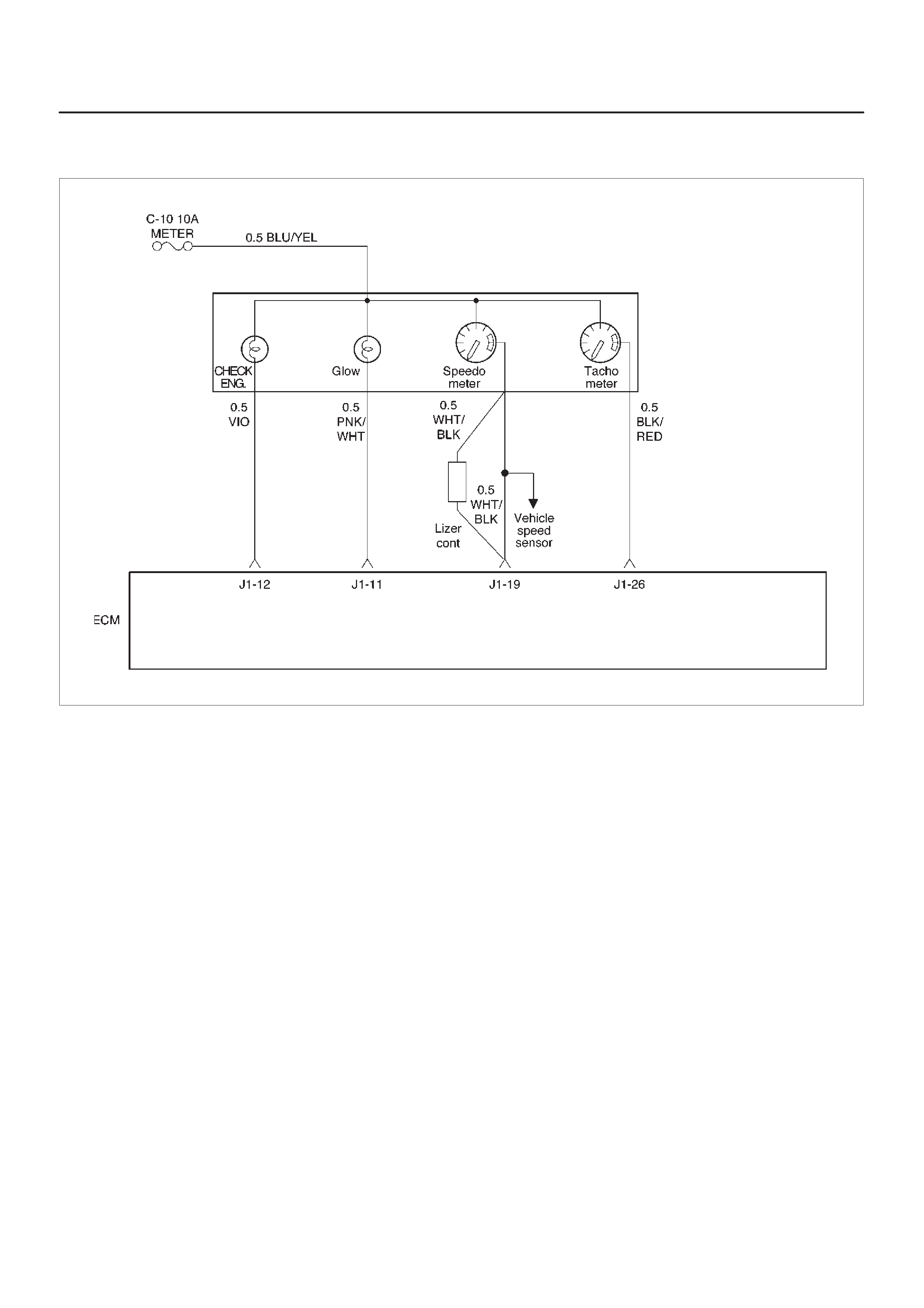
Diagnostic Trouble Code (DTC) P0654 (Flash DTC 27)
Tachometer Circuit Open/Short
060RW136
Circuit Description
The Tach Meter circuit receives through Meter 10A fuse
from the battery , current flowing in the order of Mater and
the Tach Meter.
Action Taken When the DTC Sets
DThe ECM will illuminate the malfunction indicator lamp
(MIL) the first time the fault is detected.
DThe ECM will store conditions which were present
when the DTC was set as Freeze Frame and in the
Failure Records data.
Conditions for Clearing the MIL/DTC
DDTC P0650 can be cleared by using the Tech 2 “Clear
Info” function or by disconnecting the ECM battery
feed.
Diagnostic Aids
Check for the following conditions:
DPoor connection at ECM – Inspect harness connectors
for backed-out terminals, improper mating, broken
locks, improperly formed or damaged terminals, and
poor terminal-to-wire connection.
DDamaged harness – Inspect the wiring harness for
damage.
DIf the Tech 2 indicat DTCs 0654, P0650 and P0381,
Check the meter circuit necessarily.

DTC P0654 – Tachometer Circuit Open/Short
Step Action Value(s) YesNo
1Was the “On-Board Diagnostic (OBD) System Check”
performed? —Go to
Step 2
Go to
OBD
System
Check
21. Ignition “ON,” engine “OFF.”
2. Review and record Tech 2 Failure Records data.
3. Operate the vehicle within Failure Records
conditions as noted.
4. Using a Tech 2, monitor the “DTC” info for DTC
P654.
Does the Tech 2 indicate DTC P0654 failed? —Go to
Step 3
Refer to
Diagnostic
Aids
3Check the Tach meter circuit for a poor connection at
the Meter and replace the terminal if necessary.
Did the terminal require replacement? — Verify repair Go to
Step 4
4Using the Tech 2.
Does the Tech 2 indicate DTC P0654 failed? — Verify repair Go to
Step 5
5Check the Tach Meter circuit for a poor connection.
Did the terminal require replacement? — Verify repair Go to
Step 6
6Replace the tachometer.
Is the action complete? — Verify repair Go to
Step 7
7Replace the ECM (Refer to the Data Programming in
Case of ECM change).
Is the action complete? — Verify repair —

Diagnostic Trouble Code (DTC) P1655 (Flash DTC 17)
Thermo Relay Circuit Open/Short
060RW130
Circuit Description
The thermo relay circuit receives current through air con
10A fuse from the battery, current flowing in the order of
the thermo relay and thermo SW.
Action Taken When the DTC Sets
DThe ECM will illuminate the malfunction indicator lamp
(MIL) the first time the fault is detected.
DThe ECM will store conditions which were present
when the DTC was set as Freeze Frame and in the
Failure Records data.
Conditions for Clearing the MIL/DTC
DDTC P1655 can be cleared by using the Tech 2 “Clear
Info” function or by disconnecting the ECM battery
feed.
Diagnostic Aids
Check for the following conditions:
DPoor connection at ECM – Inspect harness connectors
for backed-out terminals, improper mating, broken
locks, improperly formed or damaged terminals, and
poor terminal-to-wire connection.
DDamaged harness – Inspect the wiring harness for
damage.

DTC P1655 – Thermo Relay Circuit Open/Short
Step Action Value(s) YesNo
1Was the “On-Board Diagnostic (OBD) System Check”
performed? —Go to
Step 2
Go to
OBD
System
Check
21. Ignition “ON,” engine “OFF.”
2. Observe the “Batteri V oltage” display on the T ech 2.
Is the “Batteri Voltage” below the specified value? 11 V Go to
Step 4
Go to
Step 3
31. Ignition “ON,” engine “OFF.”
2. Review and record Tech 2 Failure Records data.
3. Operate the vehicle within Failure Records
conditions as noted.
4. Using a Tech 2, monitor the “Specific DTC” info for
DTC P1655.
Does the Tech 2 indicate DTC P1655 failed? —Go to
Step 4
Refer to
Diagnostic
Aids
4Check the Thermo Relay circuit for a poor connection
and replace the terminal if necessary.
Did the terminal require replacement? — Verify repair Go to
Step 5
5Check the Thermo Relay for damage.
Did the Thermo Relay require replacement? — Verify repair Go to
Step 6
6Check the Thermo Relay circuit for a poor connection
at the ECM and replace the terminal if necessary.
Did the terminal require replacement? — Verify repair Go to
Step 7
7Replace the ECM (Refer to the Data Programming in
Case of ECM change).
Is the action complete? — Verify repair —

Diagnostic Trouble Code (DTC) P1657 (Flash DTC 76)
ECM Main Relay Circuit Open/Short
060RW135
Circuit Description
The ECM main relay circuit receives current through ECM
50A fuse from the battery, current flowing in the order of
the ECM main relay and ECM.
Action Taken When the DTC Sets
DThe ECM will illuminate the malfunction indicator lamp
(MIL) the first time the fault is detected.
DThe ECM will store conditions which were present
when the DTC was set as Freeze Frame and in the
Failure Records data.
Conditions for Clearing the MIL/DTC
DDTC P1657 can be cleared by using the Tech 2 “Clear
Info” function or by disconnecting the ECM battery
feed.
Diagnostic Aids
Check for the following conditions:
DPoor connection at ECM – Inspect harness connectors
for backed-out terminals, improper mating, broken
locks, improperly formed or damaged terminals, and
poor terminal-to-wire connection.
DDamaged harness – Inspect the wiring harness for
damage.

DTC P1657 – ECM Main Relay Circuit Open/Short
Step Action Value(s) YesNo
1Was the “On-Board Diagnostic (OBD) System Check”
performed? —Go to
Step 2
Go to
OBD
System
Check
21. Check the Fuse 50A·ECM and 15A·Eng.
2. If the Fuse is open, replace it as necessary.
Was the Fuse open? — Verify repair Go to
Step 3
31. Ignition “ON,” engine “OFF.”
2. Review and record Tech 2 Failure Records data.
3. Operate the vehicle within Failure Records
conditions as noted.
4. Using a Tech 2, monitor the “DTC” info for DTC
P1657.
Does the Tech 2 indicate DTC P1657 failed? —Go to
Step 4
Refer to
Diagnostic
Aids
4Check the ECM Main Relay circuit between the Fuse
and the ECM Main Relay for a poor connection and
repair the terminal if necessary.
Did the terminal require repair? — Verify repair Go to
Step 5
5Check the ECM Main Relay for a damage and Replace
the ECM (Refer to the Data Programming in Case of
ECM change) Main Relay if necessary.
Did the ECM Main Relay require replacement? — Verify repair Go to
Step 6
6Check the ECM Main Relay circuit for a poor
connection at the ECM and replace the terminal if
necessary.
Did the terminal require replacement? — Verify repair Go to
Step 7
7Check the ECM Main Relay Ground circuit for a poor
connection and repair the terminal if necessary.
Did the terminal require repair? — Verify repair Go to
Step 8
8Check the ECM Main Relay power circuit for a poor
connection and repair the terminal if necessary.
Did the terminal require repair? — Verify repair Go to
Step 9
9Replace the ECM (Refer to the Data Programming in
Case of ECM change) Main Relay.
Is the action complete? — Verify repair Go to
Step 10
10 Replace the ECM (Refer to the Data Programming in
Case of ECM change).
Is the action complete? — Verify repair —
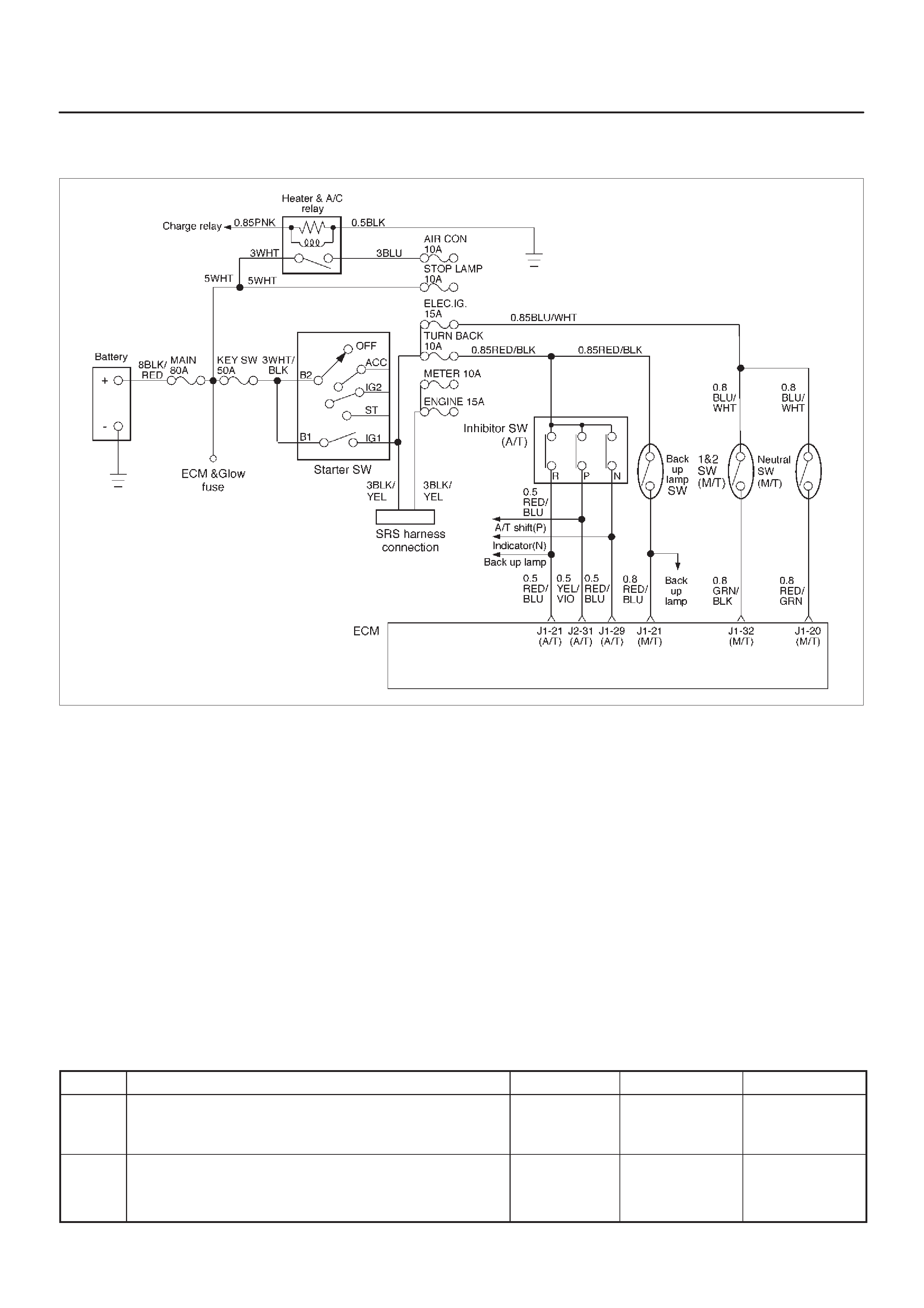
Diagnostic Trouble Code (DTC) P1589 (Flash DTC 47)
Transmission SW Circuit Open/Short
060RW131
Circuit Description
The trans mission SW circuit receives current through
ELEC IG 10A fuse from the battery, current flowing in the
order of the trans mission SW and ECM.
Action Taken When the DTC Sets
DThe ECM will illuminate the malfunction indicator lamp
(MIL) the first time the fault is detected.
DThe ECM will store conditions which were present
when the DTC was set as Freeze Frame and in the
Failure Records data.
Conditions for Clearing the MIL/DTC
DDTC P1589 can be cleared by using the Tech 2 “Clear
Info” function or by disconnecting the ECM battery
feed.
Diagnostic Aids
Check for the following conditions:
DPoor connection at ECM – Inspect harness connectors
for backed-out terminals, improper mating, broken
locks, improperly formed or damaged terminals, and
poor terminal-to-wire connection.
DDamaged harness – Inspect the wiring harness for
damage. If the harness appears to be OK, observe the
throttle position display on the Tech 2 while moving
connectors and wiring harnesses related to the TP
sensor. A change in the display will indicate the
location of the fault.
If DTC P1589 cannot be duplicated, the information
included in the Failure Records data can be useful in
determining vehicle mileage since the DTC was last set.
DTC P1589 – Transmission Circuit Open/Short
Step Action Value(s) YesNo
1Was the “On-Board Diagnostic (OBD) System Check”
performed? —Go to
Step 2
Go to
OBD
System
Check
2Check the Fuse 10A for a open circuit and replace the
Fuse if necessary.
Did the Fuse require replacement? — Verify repair Go to
Step 3

DTC P1589 – Transmission Circuit Open/Short (Cont'd)
Step NoYesValue(s)Action
3 1. Ignition “ON,” engine “OFF.”
2. Review and record Tech 2 Failure Records data.
3. Operate the vehicle within Failure Records
conditions as noted.
4. Using a Tech 2, monitor the “DTC” info for DTC
P1589.
Does the Tech 2 indicate DTC P1589 failed? —
Go to
Step 4
(A/T)
Go to
Step 6
(M/T)
Refer to
Diagnostic
Aids
4Check the Indicator Lamp correct indicated for a
correct indication on the Meter. (A/T only)
Did the Indicator Lamp correct indicated? —Go to
Step 5
Go to
Step 8
5Check the Trans Mission SW signal circuit for a poor
connection at the ECM and replace the terminal if
necessary.
Did the terminal require replacement? — Verify repair Go to
Step 8
6Check the Trans Mission SW circuit for a poor
connection at the Trans Mission SW and replace the
terminal if necessary.
Did the terminal require replacement? — Verify repair Go to
Step 7
7Replace the Trans Mission SW.
Is the action complete? — Verify repair Go to
Step 8
8Replace the ECM (Refer to the Data Programming in
Case of ECM change).
Is the action complete? — Verify repair —

Symptom Diagnosis
Preliminary Checks
Before using this section, perform the “On–Board
Diagnostic (OBD) System Check” and verify all of the
following items:
DThe powertrain control module (ECM) and
malfunction indicator lamp (MIL) (CHECK ENGINE
lamp) are operating correctly.
DThere are no DTC(s) stored.
DTech–2 data is within normal operating range. Refer
to
Typical Scan Data Values
.
DVerify the customer complaint and locate the correct
symptom in the table of contents. Perform the
procedure included in the symptom chart.
Visual/Physical Check
Several of the symptom procedures call for a careful
visual/physical check. This can lead to correcting a
problem without further checks and can save valuable
time.
This check should include the following items:
DECM grounds for cleanliness, tightness and proper
location.
DVacuum hoses for splits, kinks, and proper
connections, as shown on the “Vehicle Emission
Control Information” label. Check thoroughly for any
type of leak or restriction.
DAir intake ducts for collapsed or damaged areas.
DInjector wires for cracking, hardness, and carbon
tracking.
DWiring for proper connections, pinches and cuts.
Intermittents
IMPORTANT:An intermittent problem may or may not
turn on the malfunction indicator lamp (MIL) or store a
DTC. DO NOT use the Diagnostic Trouble Code (DTC)
charts for intermittent problems. The fault must be
present to locate the problem.
Most intermittent problems are caused by faulty electrical
connections or wiring. Perform a careful visual/physical
check for the following conditions:
DPoor mating of the connector halves or a terminal not
fully seated in the connector (backed out).
DImproperly formed or damaged terminal.
DAll connector terminals in the problem circuit should
be carefully checked for proper contact tension.
DPoor terminal–to–wire connection. This requires
removing the terminal from the connector body to
check.
Road test the vehicle with a Digital Multimeter
(5-8840-0285-0) connected to a suspected circuit. An
abnormal voltage when the malfunction occurs is a good
indication that there is a fault in the circuit being
monitored.
Use a scan tool to help detect intermittent conditions. The
scan tools have several features that can be used to
locate an intermittent condition. Use the following feature
to find intermittent faults:
DUsing a Tech–2 “Freeze Frame” buffer or “Failure
Records” buffer can aid in locating an intermittent
condition. Review and record the information in the
freeze frame or failure record associated with the
intermittent DTC being diagnosed. The vehicle can
be driven within the conditions that were present
when the DTC originally set.
To check for loss of diagnostic code memory, disconnect
the MAP sensor and idle the engine until the MIL (CHECK
ENGINE lamp) comes on. DTC P0107 should be stored
and kept in memory when the ignition is turned “OFF.” If
not, the ECM is faulty. When this test is completed, make
sure that you clear the DTC P0107 from memory.
An intermittent MIL (CHECK ENGINE lamp) with no
stored DTC may be caused by the following:
DMIL (CHECK ENGINE lamp) wire to ECM shorted to
ground.
DPoor ECM grounds. Refer to the ECM wiring
diagrams.
Check for improper installation of electrical options such
as lights, cellular phones, etc.
Check for an open diode across the A/C compressor
clutch and check for other open diodes (refer to wiring
diagrams in
Electrical Diagnosis
).

Hard Start Symptom
Step Action Value(s) YesNo
1DEFINITION:
Engine cranks, but does not start for a long time. Does
eventually run, or may start but immediately stalls.
Was the “On-Board Diagnostic (OBD) System Check”
performed? —Go to
Step 2
Go to
OBD
System
Check
21. Perform a bulletin search.
2. If a bulletin that addresses the symptom is found,
correct the condition as instructed in the bulletin.
Was a bulletin found that addresses the symptom? — Verify repair Go to
Step 3
3Was a visual/physical check performed?
—Go to
Step 4
Go to
Visual/Physic
al Check
4Check engine coolant temperature (ECT) sensor for
shift in value. After 8 hours with the hood up and the
engine not running, connect the scan tool. With the
ignition “ON” and the engine not running, compare
engine coolant temperature to manifold air
temperature.
Are ECT and MAT within the specified value of each
other? ± 5°C (± 9°F) Go to
Step 8
Go to
Step 5
51. Using Tech–2, display the engine coolant
temperature and note the value.
2. Check the resistance of the engine coolant
temperature sensor.
3. Refer to
Engine Coolant Temperature Sensor
Temperature vs. Resistance
chart on
DTC P0118
Diagnostic Support
for resistance specifications.
Is the resistance value near the resistance for the
temperature noted? —Go to
Step 7
Go to
Step 6
6Replace the ECT sensor.
Is the action complete? — Verify repair —
7Locate and repair high resistance or poor connection in
the ECT signal circuit or the ECT sensor ground.
Is the action complete? — Verify repair —
81. Injector Test
Operate the each injector by Tech 2 with the
ignition “ON” and check if the working noise
confirm.
2. If a problem is found, check the harness or replace
the injector.
Is the action complete? — Verify repair Go to
Step 9
9Check the oil rail pressure by Tech 2 at the cranking.
Is the pressure near the specified value? Less than 3
MPa Go to
Step 10
Go to
Step 11
10 Check the oil leakage on the high oil pressure line.
If the oil leakage is found, repair as necessary.
Was the oil leakage found? — Verify repair Go to
Step 11
11 1. Check for water-or alcohol-contaminated fuel.
2. If a problem is found, repair as necessary.
Was a problem found? — Verify repair Go to
Step 12
Techline

Hard Start Symptom (Cont'd)
Step NoYesValue(s)Action
12 1. Check the battery voltage.
2. If a problem is found, repair as necessary.
Was a problem found? — Verify repair Go to
Step 13
13 1. Check for the following engine mechanical
problems (Refer to
Engine Mechanical
):
DLow compression
DLeaking cylinder head gaskets
DWorn or incorrect camshaft
DCamshaft drive belt slipped or stripped
2. If a problem is found, repair as necessary.
Was a problem found? — Verify repair Go to
Step 14
14 1. Review all diagnostic procedures within this table.
2. If all procedures have been completed and no
malfunctions have been found, review/inspect the
following:
DVisual/physical inspection
DTech–2 data
DFreeze Frame data/Failure Records buffer
DAll electrical connections within a suspected
circuit and/or system.
3. If a problem is found, repair as necessary.
Was a problem found? — Verify repair
Contact
Technical
Assistance

Surges and/or Chuggles Symptom
Step Action Value(s) YesNo
1DEFINITION:
Engine power variation under steady throttle or cruise.
Feels like the vehicle speeds up and slows down with
no change in the accelerator pedal.
Was the “On-Board Diagnostic (OBD) System Check”
performed? —Go to
Step 2
Go to
OBD
System
Check
21. Perform a bulletin search.
2. If a bulletin that addresses the symptom is found,
correct the condition as instructed in the bulletin.
Was a bulletin found that addresses the symptom? — Verify repair Go to
Step 3
3Was a visual/physical check performed?
—Go to
Step 4
Go to
Visual/
Physical
Check
4Be sure that the driver understands transmission
torque converter clutch and A/C compressor operation
as explained in the owner’s manual.
Inform the customer how the TCC and the A/C clutch
operate.
Is the customer experiencing a normal condition? —System OK Go to
Step 5
51. Check the priming pump. Refer to
Fuel System
.
2. If a problem is found, operate the priming pump.
Was a problem found? — Verify repair Go to
Step 6
61. Injector Test
Operate the each injector by Tech 2 with the
ignition “ON” and check if the working noise
confirm.
2. If a problem is found, check the harness and repair
as necessary.
Is the action complete? — Verify repair Go to
Step 7
71. Check ECM grounds for the cleanliness, tightness
and proper locations. Refer to the ECM wiring
diagrams in
Electrical Diagnosis
.
2. If a problem is found, repair as necessary.
Was a problem found? — Verify repair Go to
Step 8
81. Check AP sensor connections.
2. If a problem is found, replace the faulty terminals as
necessary. Refer to
Electrical Diagnosis
for wiring
repair procedures.
Was a problem found? — Verify repair Go to
Step 9
91. Visually/physically check vacuum hoses for splits,
kinks, and proper connections and routing as
shown on the “Vehicle Emission Control
Information” label.
2. If a problem is found, repair as necessary.
Was a problem found? — Verify repair Go to
Step 10

Surges and/or Chuggles Symptom (Cont'd)
Step NoYesValue(s)Action
10 1. Check the exhaust system for possible restriction:
DInspect the exhaust system for damaged or
collapsed pipes.
DInspect the muffler for heat distress or possible
internal failure.
DCheck for a possible plugged catalytic
converter by checking the exhaust system
back pressure. Refer to
Restricted Exhaust
System Check
.
2. If a problem is found, repair as necessary.
Was a problem found? — Verify repair Go to
Step 11
11 1. Review all diagnostic procedures within this table.
2. If all procedures have been completed and no
malfunctions have been found, review/inspect the
following:
DVisual/physical inspection
DTech 2 data
DFreeze Frame data/Failure Records buffer
DAll electrical connections within a suspected
circuit and/or system.
3. If a problem is found, repair as necessary.
Was a problem found? — Verify repair
Contact
Technical
Assistance

Lack of Power, Sluggish or Spongy Symptom
Step Action Value(s) YesNo
1DEFINITION:
Engine delivers less than expected power. Little or no
increase in speed when accelerator pedal is pushed
down part-way.
Was the “On-Board Diagnostic (OBD) System Check”
performed? —Go to
Step 2
Go to
OBD
System
Check
21. Perform a bulletin search.
2. If a bulletin that addresses the symptom is found,
correct the condition as instructed in the bulletin.
Was a bulletin found that addresses the symptom? — Verify repair Go to
Step 3
3Was a visual/physical check performed?
—Go to
Step 4
Go to
Visual/
Physical
Check
41. Remove and check the air filter element for dirt or
restrictions. Refer to
Air Intake System
in
On-Vehicle Service
.
2. Replace the air filter element if necessary.
Was a repair required? — Verify repair Go to
Step 5
51. Check AP sensor system. Refer to
AP sensor
diagnostic
.
2. If a problem is found, repair as necessary.
Was a problem found? — Verify repair Go to
Step 6
61. Check for water-or alcohol-contaminated fuel.
2. If a problem is found, repair as necessary.
Was a problem found? — Verify repair Go to
Step 7
71. Using a Tech 2, Injector test.
2. If a problem is found, repair as necessary.
Was a problem found? — Verify repair Go to
Step 8
81. Check the ECM grounds for the cleanliness,
tightness and proper locations. Refer to the ECM
wiring diagrams in
Electrical Diagnosis
.
2. If a problem is found, repair as necessary.
Was a problem found? — Verify repair Go to
Step 9
91. Check the exhaust system for possible restriction:
DInspect the exhaust system for damaged or
collapsed pipes.
DInspect the muffler for heat distress or possible
internal failure.
DCheck for a possible plugged catalytic
converter by checking the exhaust system
back pressure. Refer to
Restricted Exhaust
System Check
.
2. If a problem is found, repair as necessary.
Was a problem found? — Verify repair Go to
Step 10
10 1. Check the torque converter clutch (TCC) for proper
operation. Refer to
Transmission Diagnosis
.
2. If a problem is found, repair as necessary.
Was a problem found? — Verify repair Go to
Step 11
Techline

Lack of Power, Sluggish or Spongy Symptom (Cont'd)
Step NoYesValue(s)Action
11 1. Check for an engine mechanical problem. Check
for low compression, incorrect or worn camshaft,
loose timing belt, etc. Refer to
Engine Mechanical
.
2. If a problem is found, repair as necessary.
Was a problem found? — Verify repair Go to
Step 12
12 1. Review all diagnostic procedures within this table.
2. If all procedures have been completed and no
malfunctions have been found, review/inspect the
following:
DVisual/physical inspection
DTech 2 data
DFreeze Frame data/Failure Records buffer
DAll electrical connections within a suspected
circuit and/or system.
3. If a problem is found, repair as necessary.
Was a problem found? — Verify repair
Contact
Technical
Assistance

Rough, Unstable, or Incorrect Idle, Stalling Symptom
Step Action Value(s) YesNo
1DEFINITION:
Engine runs unevenly at idle. If severe, the engine or
vehicle may shake. Engine idle speed may vary in
RPM. Either condition may be severe enough to stall
the engine.
Was the “On-Board Diagnostic (OBD) System Check”
performed? —Go to
Step 2
Go to
OBD
System
Check
21. Perform a bulletin search.
2. If a bulletin that addresses the symptom is found,
correct the condition as instructed in the bulletin.
Was a bulletin found that addresses the symptom? —Go to
Step 6
Go to
Step 3
3Was a visual/physical check performed?
—Go to
Step 4
Go to
Visual/
Physical
Check
41. Check the ECM grounds for cleanliness, tightness
and proper routing. Refer to the ECM wiring
diagrams in
Electrical Diagnosis
.
2. If a problem is found, repair as necessary.
Was a problem found? — Verify repair Go to
Step 5
51. Check for incorrect idle speed. Ensure that the
following conditions are present:
DThe engine is fully warm.
DThe accessories are “OFF.”
2. Using a Tech 2, monitor the AP position.
Is the AP position within the specified values? 0% Go to
Step 10
Go to
Step 9
61. Visually/physically inspect for the following
conditions:
DRestricted air intake system. Check for a
possible collapsed air intake duct, restricted
air filter element, or foreign objects blocking
the air intake system.
2. If a problem is found, repair as necessary.
Was a problem found? — Verify repair Go to
Step 7
71. Injector Test
Operate the each injector by Tech 2 with the
ignition “ON” and check if the working noise
confirm.
2. If a problem is found, check the harness or replace
the injector.
Is the action complete? — Verify repair Go to
Step 8
81. Check the transmission range switch circuit. Use a
Tech 2 and be sure the Tech 2 indicates that the
vehicle is in drive with the gear selector in drive or
overdrive.
2. If a problem is found, diagnose and repair the
transmission range switch as necessary (Refer to
Automatic Transmission Diagnosis
).
Was a problem found? — Verify repair Go to
Step 9

Rough, Unstable, or Incorrect Idle, Stalling Symptom (Cont'd)
Step NoYesValue(s)Action
91. Check for the following engine mechanical items.
Refer to
Engine Mechanical
for diagnosis
procedures:
DLow compression
DSticking or leaking valves
DWorn camshaft lobe(s)
DCamshaft drive belt slipped or stripped
DIncorrect valve timing
DValves clearance
DBroken valve springs
2. If a problem is found, repair as necessary.
Was a problem found? — Verify repair Go to
Step 10
10 1. Check for faulty engine mounts. Refer to
Engine
Mechanical
for inspection of mounts.
2. If a problem is found, repair as necessary.
Was a problem found? — Verify repair Go to
Step 11
11 1. Review all diagnostic procedures within this table.
2. If all procedures have been completed and no
malfunctions have been found, review/inspect the
following:
DVisual/physical inspection
DTech 2 data
DFreeze Frame data/Failure Records buffer
DAll electrical connections within a suspected
circuit and/or system.
3. If a problem is found, repair as necessary.
Was a problem found? — Verify repair
Contact
Technical
Assistance

Poor Fuel Economy Symptom
Step Action Value(s) YesNo
1DEFINITION:
Fuel economy, as measured by an actual road test, is
noticeably lower than expected. Also, economy is
noticeably lower than it was on this vehicle at one time,
as previously shown by an actual road test. (Larger than
standard tires will cause odometer readings to be
incorrect, and that may cause fuel economy to appear
poor when it is actually normal.)
Was the “On-Board Diagnostic (OBD) System Check”
performed? —Go to
Step 2
Go to
OBD
System
Check
21. Perform a bulletin search.
2. If a bulletin that addresses the symptom is found,
correct the condition as instructed in the bulletin.
Was a bulletin found that addresses the symptom? — Verify repair Go to
Step 3
3Was a visual/physical check performed?
—Go to
Step 4
Go to
Visual/
Physical
Check
4Check owner’s driving habits.
DIs the A/C “ON” full time (defroster mode “ON”)?
DAre tires at the correct pressure?
DAre excessively heavy loads being carried?
DIs acceleration too much, too often?
DIs engine oil correct?
Was a problem found? —Go to
Step 5
Go to
Step 6
5Review the items in Step 4 with the customer and
advise as necessary.
Is the action complete? —System OK —
61. Visually/physically check: V acuum hoses for splits,
kinks, and improper connections and routing as
shown on the “Vehicle Emission Control
Information” label.
2. If a problem is found, repair as necessary.
Was a repair required? — Verify repair Go to
Step 7
71. Remove and check the air filter element for dirt or for
restrictions. Refer to
Air Intake System
.
2. Replace the air filter element if necessary.
Was a repair required? — Verify repair Go to
Step 8
81. Check for low engine coolant level. Refer to
Engine
Cooling
.
2. If a problem is found, repair as necessary.
Was a problem found? — Verify repair Go to
Step 9
91. Check for an incorrect or faulty engine thermostat.
Refer to
Engine Cooling
.
2. If a problem is found, repair as necessary.
Was a problem found? — Verify repair Go to
Step 10
10 1. Check for low engine compression. Refer to
Engine
Mechanical
.
2. If a problem is found, repair as necessary.
Was a problem found? — Verify repair Go to
Step 11

Poor Fuel Economy Symptom (Cont'd)
Step NoYesValue(s)Action
11 1. Check the TCC operation. Refer to
Transmission
Diagnosis
.
2. If a problem is found, repair as necessary.
Was a problem found? — Verify repair Go to
Step 12
12 1. Check the exhaust system for possible restriction:
DInspect the exhaust system for damaged or
collapsed pipes.
DInspect the muffler for heat distress or possible
internal failure.
2. If a problem is found, repair as necessary.
Was a problem found? — Verify repair Go to
Step 13
13 Check for proper calibration of the speedometer.
Does the speed indicated on the speedometer closely
match the vehicle speed displayed on the Tech 2? —Go to
Step 15
Go to
Step 14
14 Diagnose and repair an inaccurate speedometer
condition as necessary. Refer to
Vehicle Speed
Sensor
in
Electrical Diagnosis
.
Was a problem found? — Verify repair —
15 1. Check the air intake system and the crankcase for
air leaks. Refer to
Air Intake System
and
Crankcase Ventilation System
.
2. If a problem is found, repair as necessary.
Was a problem found? — Verify repair Go to
Step 16
16 1. Review all diagnostic procedures within this table.
2. When all procedures have been completed and no
malfunctions have been found, review/inspect the
following:
DVisual/physical inspection
DTech 2 data
DFreeze Frame data/Failure Records buffer
DAll connections within a suspected circuit
and/or system.
3. If a problem is found, repair as necessary.
Was a problem found? — Verify repair Go to
Step 17
17 Perform the procedure in
Injector Test
.
Was the fuel pressure normal? —
Contact
Technical
Assistance Verify repair

Excessive Exhaust Emissions or Odors Symptom
Step Action Value(s) YesNo
1DEFINITION:
Vehicle fails an emission test. Vehicle has excessive
“rotten egg” smell. (Excessive odors do not necessarily
indicate excessive emissions.)
Was the “On-Board Diagnostic (OBD) System Check”
performed? —Go to
Step 2
Go to
OBD
System
Check
21. Perform a bulletin search.
2. If a bulletin that addresses the symptom is found,
correct the condition as instructed in the bulletin.
Was a bulletin found that addresses the symptom? — Verify repair Go to
Step 3
3Was a thorough visual/physical check performed?
—Go to
Step 4
Go to
Visual/
Physical
Check
41. Check for vacuum leaks. Check vacuum lines,
intake manifold, throttle body, etc.
2. If a problem is found, repair as necessary.
Were any vacuum leaks located? — Verify repair Go to
Step 5
51. Check the fuel cap for proper installation.
2. Secure the fuel cap if necessary.
Was the fuel cap installed properly? —Go to
Step 6
Verify repair
61. Injector Test
Operate the each injector by Tech 2 with the
ignition “ON” and check if the working noise
confirm.
2. If a problem is found, check the harness or replace
the injector.
Is the action complete? — Verify repair Go to
Step 7
71. Refer to
Engine Cooling
for cooling system
diagnosis.
2. If a problem is found, repair as necessary.
Was a problem found? — Verify repair Go to
Step 8
81. Check for an engine mechanical problem.
Perform a cylinder compression check (Refer to
Engine Mechanical
).
2. If a problem is found, repair as necessary.
Was a problem found? — Verify repair Go to
Step 9
91. Review all diagnostic procedures within this table.
2. If all procedures have been completed and no
malfunctions have been found, review/inspect the
following:
DVisual/physical inspection
DTech 2 data
DFreeze Frame data/Failure Records butter
DAll electrical connections within a suspected
circuit and/or system.
3. If a problem is found, repair as necessary.
Was a problem found? — Verify repair
Contact
Technical
Assistance

Dieseling, Run-On Symptom
Step Action Value(s) YesNo
1DEFINITION:
Engine continues to run after key is turned “OFF,” but
runs very rough. If engine runs smooth, check ignition
switch and adjustment.
Was the “On-Board Diagnostic (OBD) System Check”
performed? —Go to
Step 2
Go to
OBD
System
Check
21. Perform a bulletin search.
2. If a bulletin that addresses the symptom is found,
correct the condition as instructed in the bulletin.
Was a bulletin found that addresses the symptom? — Verify repair Go to
Step 3
3Was a visual/physical check performed?
—Go to
Step 4
Go to
Visual/
Physical
Check
41. Check for a short between B+ and any of the ignition
feed circuits.
2. If a problem is found, repair as necessary.
Was a problem found? — Verify repair Go to
Step 5
51. Review all diagnostic procedures within this table.
2. If all procedures have been completed and no
malfunctions have been found, review/inspect the
following:
DVisual/physical inspection
DTech 2 data
DFreeze Frame data/Failure Records butter
DAll electrical connections within a suspected
circuit and/or system
3. If a problem is found, repair as necessary.
Was a problem found? — Verify repair
Contact
Technical
Assistance

Cuts Out, Symptom
Step Action Value(s) YesNo
1DEFINITION:
Steady pulsation or jerking that follows engine speed;
usually more pronounced as engine load increases.
Was the “On-Board Diagnostic (OBD) System Check”
performed? —Go to
Step 2
Go to
OBD
System
Check
21. Perform a bulletin search.
2. If a bulletin that addresses the symptom is found,
correct the condition as instructed in the bulletin.
Was a bulletin found that addresses the symptom? —Go to
Step 7
Go to
Step 3
3Was a visual/physical check performed?
—Go to
Step 4
Go to
Visual/
Physical
Check
41. Check the ECM grounds for clearness, tightness
and proper routing. Refer to the ECM wiring
diagrams in
Electrical Diagnosis
.
2. If a problem is found, repair as necessary.
Was a problem found? — Verify repair Go to
Step 5
51. Check for incorrect idle speed. Ensure that the
following conditions are present:
DThe engine is fully warm.
DThe accessories are “off.”
2. Using a Tech 2, monitor the AP position.
Is the AP position within the specified values? 0% Go to
Step 6
Go to
Step 7
61. Visually/physically inspect for the following
conditions:
DRestricted air intake system. Check for a
possible collapsed air intake duct, restricted
air filter element, or foreign objects blocking
the air intake system.
DCheck the Throttle body.
DLarge vacuum leak. Check for a condition that
causes a large vacuum leak, such as an
incorrectly installed or faulty VSV or brake
booster hose disconnected .
2. If a problem is found, repair as necessary.
Was a problem found? — Verify repair Go to
Step 7
7Using a Tech 2, monitor the AP angle with the engine
idling.
Is the AP angle at the specified value and steady? 0% Go to
Step 8
Refer to
DTC
P0123
for
further
diagnosis
81. Check the transmission range switch circuit. Use a
Tech 2 and be sure the Tech 2 indicates that the
vehicle is in drive with the gear selector in drive or
overdrive.
2. If a problem is found, diagnose and repair the
transmission range switch as necessary.
Was a problem found? — Verify repair Go to
Step 9

Cuts Out, Symptom (Cont'd)
Step NoYesValue(s)Action
91. Injector Test
Operate the each injector by Tech 2 with the
ignition “ON” and check if the working noise
confirm.
2. If a problem is found, check the harness or replace
the injector.
Is the action complete? — Verify repair Go to
Step 10
10 1. Check the following engine mechanical items.
Refer to
Engine Mechanical
for diagnosis
procedures:
DLow compression
DSticking or leaking valves
DWorn camshaft lobe(s)
DCamshaft drive belt slipped or stripped
DIncorrect valve timing
DBroken valve springs
2. If a problem is found, repair as necessary.
Was a problem found? — Verify repair Go to
Step 11
11 1. Check for faulty motor mounts. Refer to
Engine
Mechanical
for inspection of mounts.
2. If a problem is found, repair as necessary.
Was a problem found? — Verify repair Go to
Step 12
12 1. Review all diagnostic procedures within this table.
2. If all procedures have been completed and no
malfunctions have been found, review/inspect the
following:
DVisual/physical inspection
DTech 2 data
DFreeze Frame data/Failure Records butter
DAll electrical connections within a suspected
circuit and/or system
3. If a problem is found, repair as necessary.
Was a problem found? — Verify repair
Contact
Technical
Assistance

Starter Motor Doesn’t Rotate
Step Action Value(s) Yes No
1DEFINITION:
As starter motor doesn’t rotate, engine is not cranked.
1. Perform a bulletin search.
2. If a bulletin that addresses the symptom is found,
correct the condition as instructed in the bulletin.
Was the bulletin found? — Verify repair Go to
Step 2
2Was a visual/physical check performed?
—Go to
Step 3
Go to
Visual/
Physical
Check
31. Check battery cord terminal for looseness & poor
contact due to corrosion.
2. Check battery voltage.
3. If a problem is found, repair as necessary.
Was a problem found? — Verify repair Go to
Step 4
41. Check fan belt for looseness & damage.
2. If a problem is found, adjust or replace as
necessary.
Was a problem found? — Verify repair Go to
Step 5
51. Check fuse bull link for disconnection & short.
2. If a problem is found, repair as necessary.
Was a problem found? — Verify repair Go to
Step 6
61. Check generator for mount & damage (Refer to
Engine Mechanical).
2. If a problem is found, repair as necessary.
Was a problem found? — Verify repair Go to
Step 7
71. Check starter SW and starter relay for looseness
and damage.
2. If a problem is found, repair as necessary.
Was a problem found? — Verify repair Go to
Step 8
81. Check starter motor for mount and damage. (Refer
to
Engine Mechanical
)
2. If a problem is found, repair as necessary.
Was a problem found? — Verify repair Go to
Step 9
91. Review all diagnostic procedures within this table.
2. If all procedures have been completed and no
malfunctions have been found, review/inspect the
following:
DVisual/physical inspection
DTech 2 data
DFreeze Frame data/Failure Records butter
DAll electrical connections within a suspected
circuit and/or system
3. If a problem is found, repair as necessary.
Was a problem found? — Verify repair
Contact
Technical
Assistance

Starting Difficulty In Case Fuel Doesn’t Come to Injector
Step Action Value(s) YesNo
1DEFINITION:
Engine is cranked, but not started for a long time. Steps
soon.
Was OBD System check performed? —Go to
Step 2
Go to
OBD
System
Check
21. Perform a bulletin research.
2. If a bulletin that addresses the symptom is found,
correct the condition as instructed in the bulletin.
Was a bulletin found? — Verify repair Go to
Step 3
3Was a visual/physical check performed?
—Go to
Step 4
Go to
Visual/
Physical
Check
4Check fuel shortage. If short, replenish.
Was fuel short? —Verify
replenish Go to
Step 5
51. Check fuel pipeline for leak.
2. If a problem is found, repair as necessary.
Was a problem found? — Verify repair Go to
Step 6
61. Check fuel pipeline & filter for deformation &
clogging.
2. If a problem is found, repair as necessary.
Was a problem found? — Verify repair Go to
Step 7
71. Check fuel pump for damage.
2. If a problem is found, repair as necessary.
Was a problem found? — Verify repair Go to
Step 8
8Check the Injector test by Tech 2.
Does the working noise confirm? —Go to
Step 11
Go to
Step 9
91. Check the injector connector for damage.
2. Check the injector harness for damage.
3. If a problem is found, repair as necessary.
Was a problem found? — Verify repair Go to
Step 10
10 Replace the injector. (Refer to the
injector group sign
programming)
Is the action complete? — Verify repair —
11 1. Indicate RPCV Data List by Tech 2 to check
operation. Perform RPCV test.
2. If a problem is found, replace RP sensor or RPCV
as necessary.
Was a problem found? — Verify repair Go to
Step 12

Starting Difficulty In Case Fuel Doesn’t Come to Injector (Cont'd)
Step NoYesValue(s)Action
12 1. Review all diagnostic procedures within this table.
2. If all procedures have been completed and no
malfunctions have been found, review/inspect the
following:
DVisual/physical inspection
DTech 2 data
DFreeze Frame data/Failure Records butter
DAll electrical connections within a suspected
circuit and/or system
3. If a problem is found, repair as necessary.
Was a problem found? — Verify repair
Contact
Technical
Assistance

Lubrication System Trouble
Step Action Value(s) YesNo
1DEFINITION:
In road tests oil pressure doesn’t rise, or oil is foul to
excess.
Was OBD System check performed? —Go to
Step 2
Go to
OBD
System
Check
21. Perform a bulletin research.
2. If a bulletin that addresses the symptom is found,
correct the condition as instructed in the bulletin.
Was a bulletin found? — Verify repair Go to
Step 3
31. Check if a correct engine oil is used.
2. If a problem is found, change engine oil.
Was a problem found? — Verify repair Go to
Step 4
41. Check the oil pressure meter for damage.
2. Check the oil unit harness and connector for
damage.
3. If a problem is found, repair as necessary.
Was a problem found? — Verify repair Go to
Step 5
51. Check oil pipe connections for leakage.
2. If a problem is found, repair as necessary.
Was a problem found? — Verify repair Go to
Step 6
61. Check oil filter for clogging.
2. If a problem is found, repair as necessary.
Was a problem found? — Verify repair Go to
Step 7
71. Check valve clearance.
2. If a problem is found, adjust as necessary.
Was a problem found? — Verify repair Go to
Step 8
81. Check camshaft bearing for wear.
2. If a problem is found, repair as necessary.
Was a problem found? — Verify repair Go to
Step 9
91. Check crankshaft & connecting rod bearings for
wear.
2. If a problem is found, repair as necessary.
Was a problem found? — Verify repair Go to
Step 10
10 1. Check oil pump for damage.
2. If a problem is found, repair as necessary.
Was a problem found? — Verify repair Go to
Step 11

Lubrication System Trouble (Cont'd)
Step NoYesValue(s)Action
11 1. Check cylinder head & cam carrier gaskets for
damage.
2. If a problem is found, repair or replace as
necessary.
Was a problem found? — Verify repair Go to
Step 12
12 1. Review all diagnostic procedures within this table.
2. If all procedures have been completed and no
malfunctions have been found, review/inspect the
following:
DVisual/physical inspection
DTech 2 data
DFreeze Frame data/Failure Records butter
DAll electrical connections within a suspected
circuit and/or system
3. If a problem is found, repair as necessary.
Was a problem found? — Verify repair
Contact
Technical
Assistance

QOS System Doesn’t Work
Step Action Value(s) YesNo
1Was OBD System check performed?
—Go to
Step 2
Go to
OBD
System
Check
2Check glawplug indicator light. If bulb is broken,
replace.
Was a problem found? — Verify repair Go to
Step 3
31. Connect a circuit tester between glawplug & engine
ground.
2. With ignition on and engine off, check if the glaw
indicator and circuit tester indicate power voltage
for 9 to 13 sec. If not indicated, repair terminal & wire
harness.
Was repair needed? — Verify repair Go to
Step 4
41. Connect a circuit tester between glawplug and
engine ground.
2. With engine on, check if voltage continues for 180
sec. If not, inspect and repair glaw relay.
Was repair needed? — Verify repair Go to
Step 5
51. Remove the glawplug, and if damaged, replace.
2. Check glawplug resistance.
Was resistance as specified? 0.8 – 1WGo to
Step 7
Go to
Step 6
6Replace glawplug.
Was measure completed? — Verify repair Go to
Step 7
71. Review all diagnostic procedures within this table.
2. If all procedures have been completed and no
malfunctions have been found, review/inspect the
following:
DVisual/physical inspection
DTech 2 data
DFreeze Frame data/Failure Records butter
DAll electrical connections within a suspected
circuit and/or system
3. If a problem is found, repair as necessary.
Was a problem found? — Verify repair
Contact
Technical
Assistance

Much Black Smoke in Exhaust Gas
Step Action Value(s) YesNo
1DEFINITION:
In road tests, much black smoke is mixed.
Was OBD System check performed? —Go to
Step 2
Go to
OBD
System
Check
21. Perform a bulletin research.
2. If a bulletin that addresses the symptom is found,
correct the condition as instructed in the bulletin.
Was a bulletin found? — Verify repair Go to
Step 3
31. Check if a correct fuel is used.
2. If a problem is found, change fuel.
Was a problem found? — Verify repair Go to
Step 4
41. Check air cleaner element for clogging.
2. If a problem is found, repair or replace as
necessary.
Was a problem found? — Verify repair Go to
Step 5
51. Connect Tech 2 to the vehicle.
2. Monitor data list to check injector function.
3. If a problem is found, repair as necessary.
Was a problem found? — Verify repair Go to
Step 6
61. Connect Tech 2 to the vehicle.
2. Monitor RPCV test to check rpcv function.
3. If a problem is found, repair as necessary.
Was a problem found? — Verify repair Go to
Step 7
71. Check valve clearance.
2. If a problem is found, adjust as necessary.
Was a problem found? — Verify repair Go to
Step 8
81. Review all diagnostic procedures in this table.
2. If all procedures have been completed and no
malfunctions have been found, review/inspect the
following:
DVisual/physical check
DTech 2 data list
DFreeze Frame data
DAll electrical connections in suspected circuits
& systems
3. If a problem is found, repair as necessary.
Was a problem found? — Verify repair
Contact
Technical
Assistance

Excess Engine Oil Consumption
Step Action Value(s) YesNo
1DEFINITION:
Oil consumption measured in road tests is higher than
expected.
Was OBD System check performed? —Go to
Step 2
Go to
OBD
System
Check
21. Perform a bulletin research.
2. If a bulletin that addresses the symptom is found,
correct the condition as instructed in the bulletin.
Was a bulletin found? — Verify repair Go to
Step 3
31. Check if a correct engine oil is used.
2. If a problem is found, change engine oil.
Was a problem found? — Verify repair Go to
Step 4
41. Check oil pipe connections for leakage.
2. If a problem is found, repair as necessary.
Was a problem found? — Verify repair Go to
Step 5
51. Check oil seals and gaskets for leakage.
2. If a problem is found, repair as necessary.
Was a problem found? — Verify repair Go to
Step 6
61. Connect Tech 2 to the vehicle.
2. Perform RPCV test to check its function.
3. If a problem is found, repair as necessary.
Was a problem found? — Verify repair Go to
Step 7
71. Check piston ring for damage & groove wear.
2. If a problem is found, repair as necessary.
Was a problem found? — Verify repair Go to
Step 8
81. Check valve stem, valve guide and oil controller for
wear.
2. If a problem is found, repair as necessary.
Was a problem found? — Verify repair Go to
Step 9
91. Check camshaft carrier & cylinder head gaskets for
blow-by.
2. If a problem is found, repair or replace as
necessary.
Was a problem found? — Verify repair Go to
Step 10
10 1. Review all the diagnostic procedures in this table.
2. If all procedures have been completed and no
malfunctions have been found, review/inspect the
following:
DVisual/physical check
DTech 2 data list
DFreeze Frame data
DAll electrical connections in suspected circuits
& systems
3. If a problem is found, repair as necessary.
Was a problem found? — Verify repair
Contact
Technical
Assistance

Default Matrix Table
Service Procedure Default Strategy
A referral strategy has been established to assist the
technician with additional information when the cause of
the failure cannot be determined. If no problem is found
after performing diagnostics, then refer to the default
matrix table for further diagnostic information.
Default Matrix Table
Strategy Based Diagnostic Charts Initial Diagnosis Default Section(s)
On-Board Diagnostic (OBD) System
Check Vehicle does not enter diagnostics. Chassis Electrical
On-Board Diagnostic (OBD) System
Check Vehicle enters diagnostics and
communicates with the Tech 2. MIL is
“ON” in diagnostics. Engine does not
start and run.
HEUI System Check
On-Board Diagnostic (OBD) System
Check Engine starts and runs, no ECM codes
set. Customer complains of vibration. —
On-Board Diagnostic (OBD) System
Check Engine starts and runs, no ECM codes
set. Customer complains of harsh or
soft shift, poor performance, delayed or
no engagement into drive or reverse,
transmission fluid leak, transmission
noise or vibration, or improper TCC
operation.
Automatic Transmission
ECM Power and Ground Check On-Board Diagnostic (OBD) System
Check. Chassis Electrical
ECM Power and Ground Check On-Board Diagnostic (OBD) System
Check. ECM power and ground circuits
OK. Data link voltage incorrect.
Chassis Electrical
On-Board Diagnostic (OBD) System
Check Engine starts and runs, no ECM codes
set. Customer complains of harsh or
soft shift, poor performance, delayed or
no engagement into drive or reverse,
transmission fluid leak, transmission
noise or vibration, or improper TCC
operation.
Automatic Transmission
Symptoms Initial Diagnosis Default Section(s)
Intermittents 1. On-board diagnostic (OBD)
system check.
2. Careful visual/physical inspections.
Chassis Electrical
Hard Starts 1. OBD system check.
2. Sensors (ECT, MAP, EGR, AP) ;
output chart.
3. Fuel system electrical test, fuel
system diagnosis.
4. Injector system.
Engine Mechanical, Injector
System Check, Exhaust System
Diagnosis
Surges and/or Chuggles 1. OBD system check.
2. Fuel system diagnosis.
3. Injector system.
Calibration ID “Broadcast”
/Service Bulletins, Ignition
System Check, Generator
Output, Exhaust System
Diagnosis
Lack of Power, Sluggish or Spongy 1. OBD system check.
2. Fuel system diagnosis.
3. Injector system.
Refer to
Exhaust System
in
Engine Exhaust
, TCC
Operation, Calibration
ID/Service Bulletins

Symptoms Initial Diagnosis Default Section(s)
Hesitation, Sag, Stumble 1. OBD system check.
2. AP.
3. MAP output check.
4. Fuel system diagnosis.
5. Injector system.
Generator Output Voltage (refer
to
Chassis Electrical
),
Calibration ID/Service Bulletins,
Ignition System Check
Rough, Unstable, or Incorrect Idle,
Stalling 1. OBD system check.
2. Fuel injector test. MAP Output Check, Throttle
Linkage, A/C Clutch Control
Circuit Diagnosis, Calibration
ID/Service Bulletins, Generator
Output Voltage (refer to
Chassis
Electrical
), Exhaust Diagnosis
Poor Fuel Economy 1. OBD system check.
2. Careful visual/physical inspection.
3. Injector system.
4. Cooling system.
TCC Operation, Exhaust
System (refer to
Engine
Exhaust
)
Engine Cranks But Will Not Run 1. OBD system check. Fuel System Electrical
Diagnosis, Fuel System
Diagnosis, Fuel Injector Test.
Excessive Exhaust Emissions or
Odors 1. OBD system check.
2. Emission test.
3. Cooling system.
4. Fuel system diagnosis.
5. Fuel injector test.
6. Injector system.
7. MAP output check.
Exhaust Diagnosis, Calibration
ID/Service Bulletins
Dieseling, Run-On 1. OBD system check.
2. Careful visual/physical inspection.
3. Fuel system diagnosis.
—
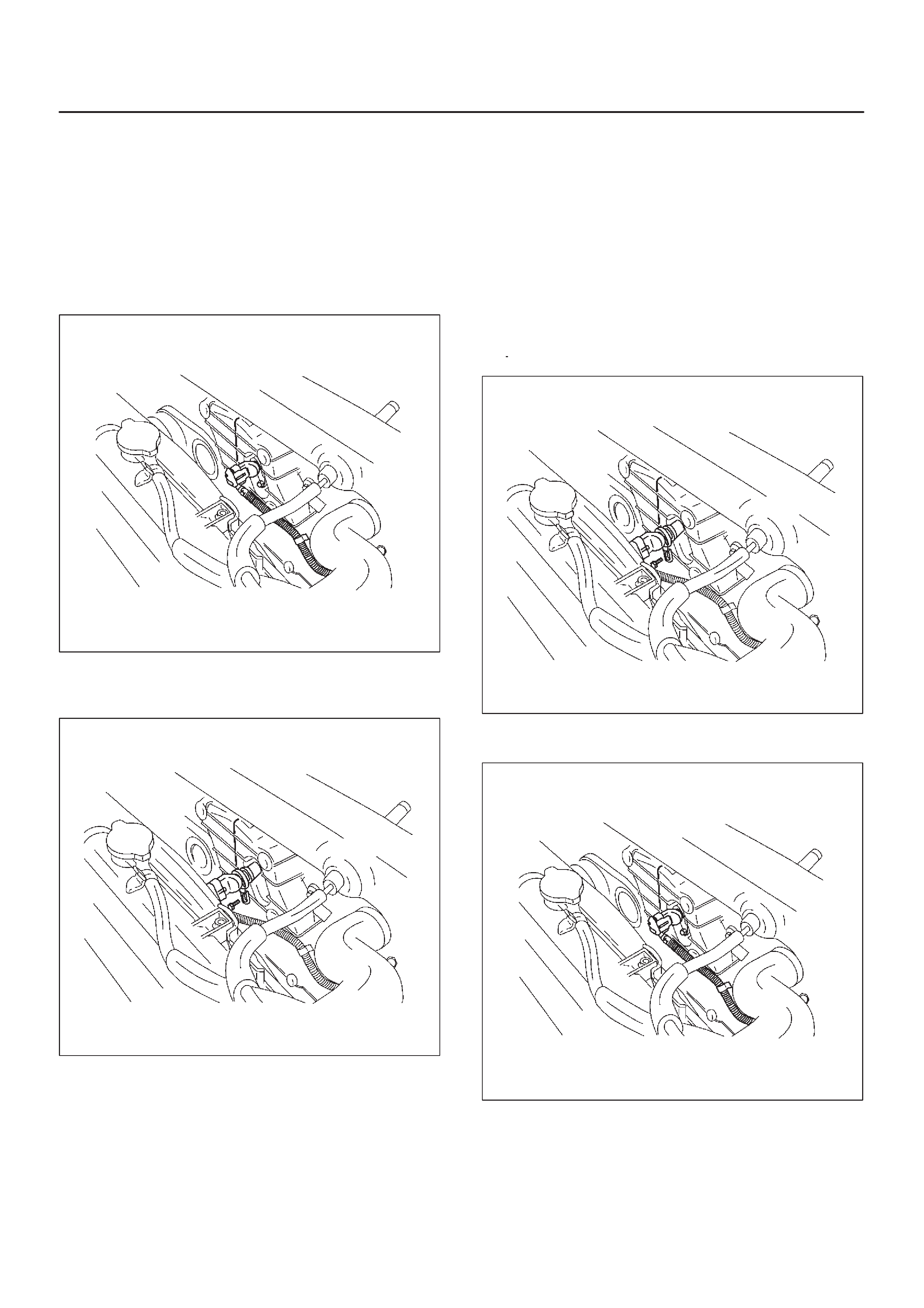
On–Vehicle Service
Camshaft Position (CMP)
Sensor
Removal Procedure
1.Disconnect the negative battery cable.
2.Disconnect the electrical connector to the CMP
sensor.
035RW071
3.Remove the CMP sensor retaining bolt from the
cylinder head cover.
035RW075
Inspection Procedure
1.Inspect the sensor O-ring for cracks or leaks.
2.Replace the O-ring if it is worn or damaged.
3.Lubricate the new O-ring with engine oil.
4.Install the lubricated O-ring.
Installation Procedure
1.Install the CMP sensor in the cylinder head cover.
2.Install the CMP sensor retaining bolt.
Tighten
DTighten the retaining bolt to 9 N·m (78 lb in.).
035RW075
3.Connect the electrical connector to the CMP sensor.
035RW071
4.Connect the negative battery cable.
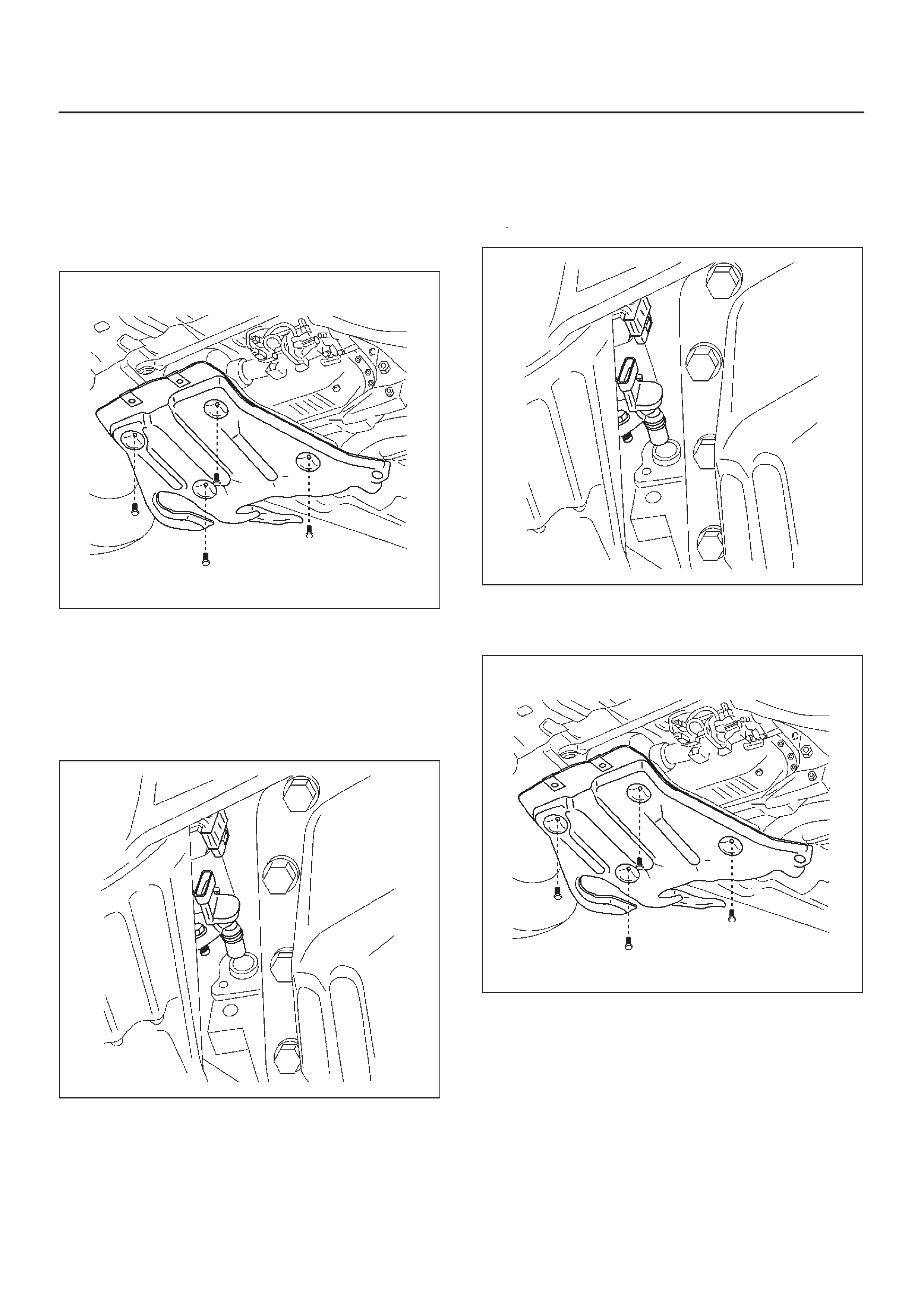
Crankshaft Position (CKP)
Sensor
Removal Procedure
1.Disconnect the negative battery cable.
2.Remove the under cover.
035RW091
3.Disconnect the electrical connector to the CKP
sensor.
4.Remove one bolt and the CKP sensor from the left
side of the engine block.
NOTE: Use caution to avoid any hot oil that might drip
out.
035RW090
Inspection Procedure
1.Inspect the sensor O-ring for cracks or leaks.
2.Replace the O-ring if it is worn or damaged.
3.Lubricate the new O-ring with engine oil.
4.Install the lubricated O-ring.
Installation Procedure
1.Install the CKP sensor in the engine block.
2.Install the CKP sensor mounting bolt.
Tighten
DTighten the mounting bolt to 9 N·m (78 lb in.).
035RW090
3.Connect the electrical connector to the CKP sensor.
4.Install the under cover.
035RW091
5.Connect the negative battery cable.
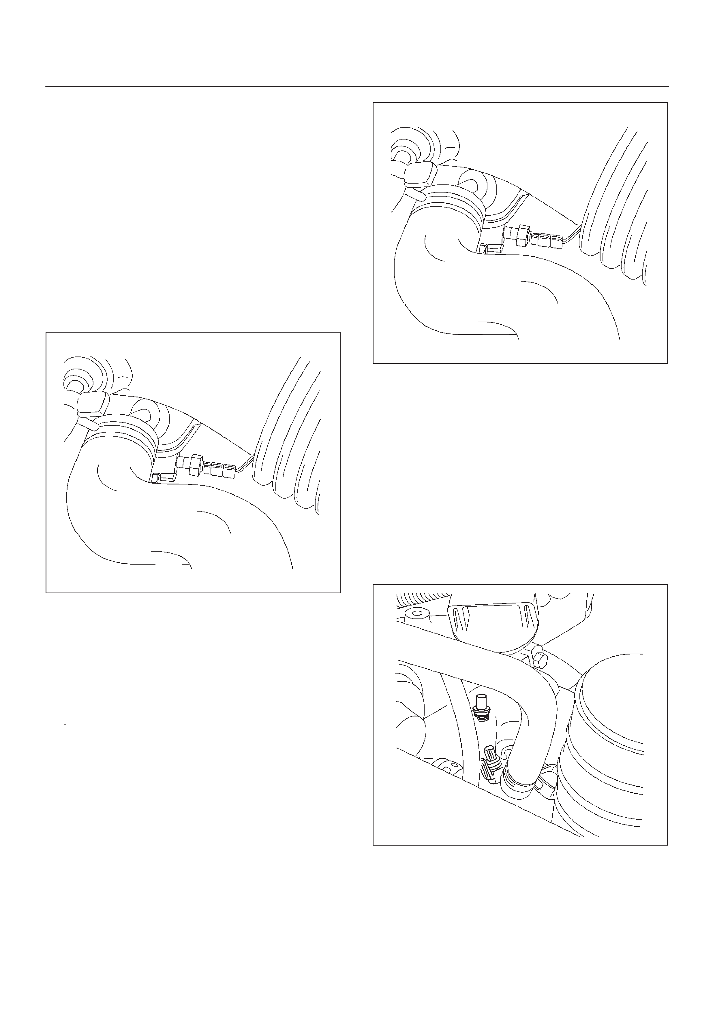
Engine Coolant Temperature
(ECT) Sensor
Removal Procedure
NOTE:Care must be taken when handling the engine
coolant temperature (ECT) sensor. Damage to the ECT
sensor will affect proper operation of the fuel injection
system.
1.Disconnect the negative battery cable.
2.Drain the radiator coolant. Refer to
Draining and
Refilling Cooling System
in
Engine Cooling
.
3.Disconnect the electrical connector.
4.Remove the ECT sensor from the front side of the
intake manifold.
035RW058
Installation Procedure
1.Apply sealer (LOCTITE 262) or the equivalent to the
threads of the ECT sensor.
2.Install the ECT sensor in the front side of the intake
manifold.
Tighten
DTighten the ECT sensor to 19 N·m (14 lb ft.).
3.Connect the electrical connector.
035RW058
4.Fill the radiator with coolant. Refer to
Draining and
Refilling Cooling System
in
Engine Cooling
.
5.Connect the negative battery cable.
Intake Air Temperature (IAT)
Sensor
Removal Procedure
1.Disconnect the negative battery cable.
2.Disconnect the electrical connector from the IAT
sensor.
3.Remove the IAT sensor from the intake air duct by
using a rocking motion while pulling the sensor.
035RW056
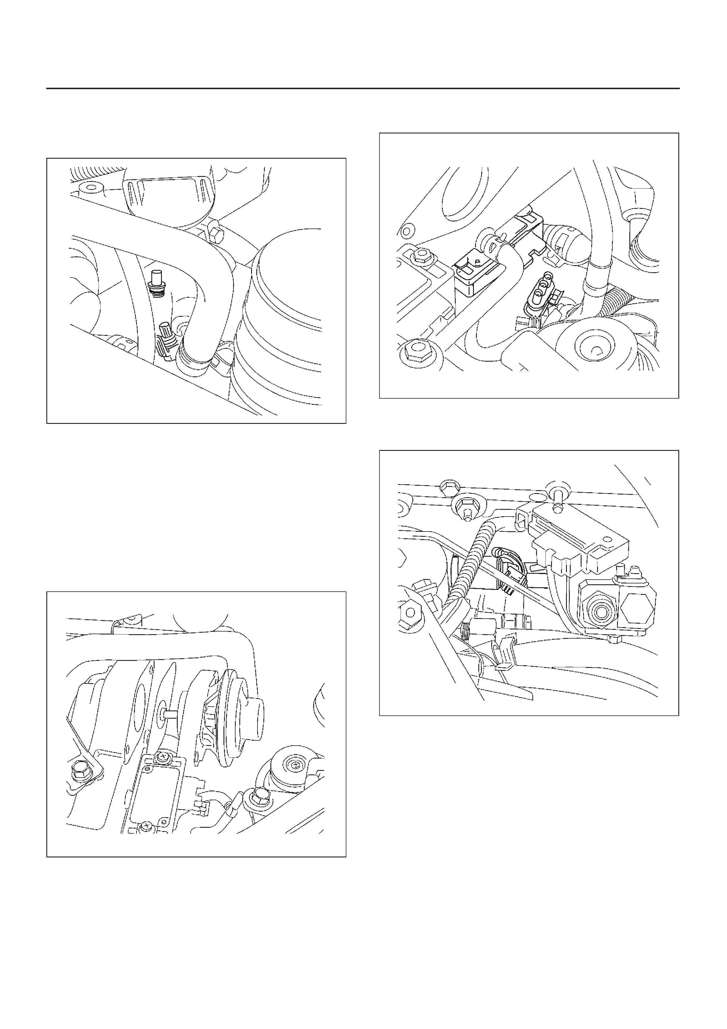
Installation Procedure
1.Install the IAT sensor into the grommet in the intake
air duct.
035RW056
2.Correct the IAT electrical connector.
3.Connect the negative battery cable.
Manifold Absolute Pressure
(MAP) Sensor
Removal Procedure
1.Disconnect the negative battery cable.
2.Disconnect the EGR valve.
035RW054
3.Disconnect the MAP sensor connector from the MAP
sensor.
035RW053
4.Remove the bolts and the MAP sensor from the
intake manifold.
035RW057
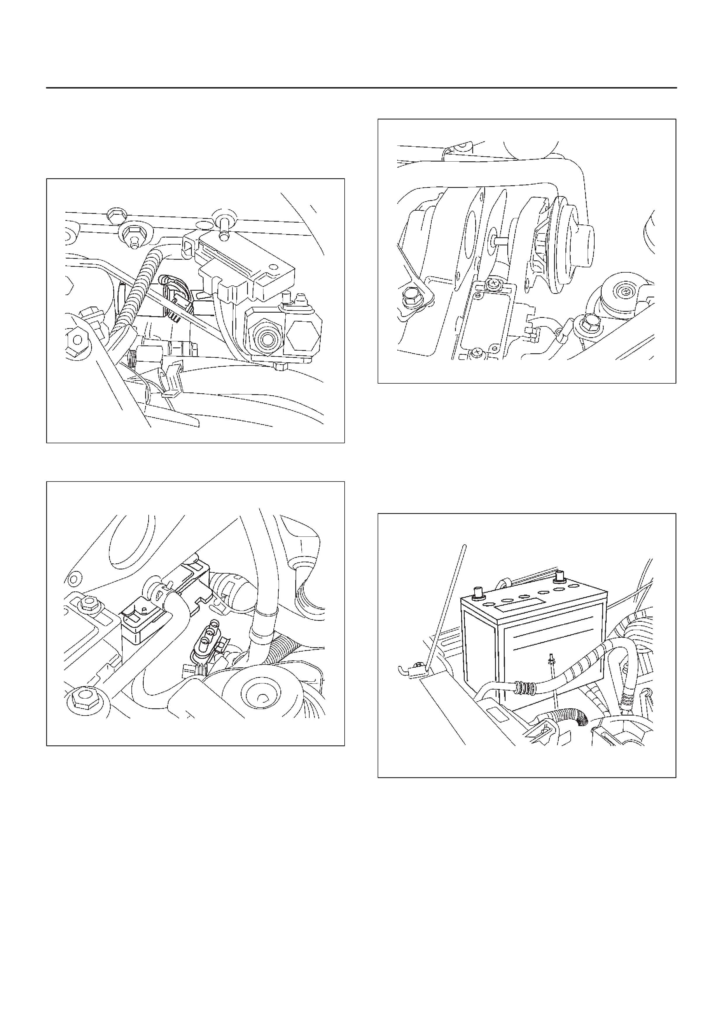
Installation Procedure
1.Install the MAP sensor and bolts on the intake
manifold.
Torque: 4 N·m (35 lb in)
035RW057
2.Connect the MAP sensor connector.
035RW053
3.Connect the EGR valve.
035RW054
4.Connect the negative battery cable.
Oil Temperature (OT) Sensor
Removal Procedure
1.Disconnect the negative battery cable.
2.Remove the battery.
035RW095
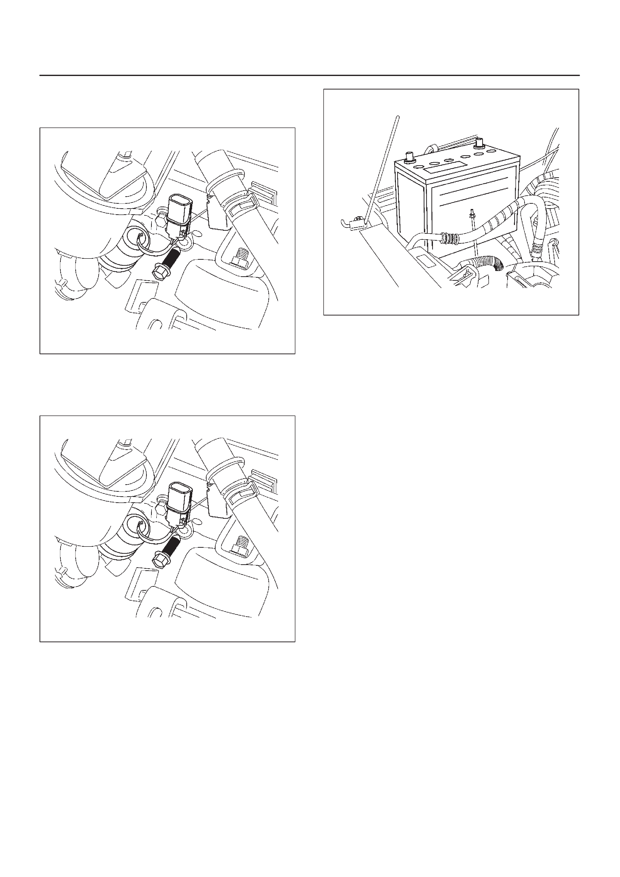
3.Disconnect the electrical connector from the OT
sensor.
4.Remove the OT sensor.
035RW061
Installation Procedure
1.Install the OT sensor.
035RW061
2.Connect the OT sensor electrical connector.
3.Install the battery.
035RW095
4.Connect the negative battery cable.
Malfunction Indicator Lamp
(MIL)
Removal and Installation Procedure
Refer to Meter in Electrical section.
Engine Control Module (ECM)
Service Precaution
NOTE: To prevent possible electrostatic discharge
damage to the ECM, do not touch the connector pins or
soldered components on the circuit board.
When replacing the ECM to prevent possible electro
damage, follow these guidelines:
Before removing the ECM, disconnect the negative
battery cable.
Before install the ECM, install the negative battery cable.
Electrostatic Discharge (ESD)
Damage
Electronic components used in the control systems are
often designed to carry very low voltage. Electronic
components are susceptible to damage caused by
electrostatic discharge. Less than 100 volts of static
electricity can cause damage to some electronic
components. By comparison, it takes as much as 4,000
volts for a person to even feel the zap of a static
discharge.
There are several ways for a person to become statically
charged. The most common methods of charging are by
friction and by induction. An example of charging by
friction is a person sliding across a car seat.
Charging by induction occurs when a person with well
insulated shoes stands near a highly charged object and
momentarily touches ground. Charges of the same
polarity are drained off leaving the person highly charged
with the opposite polarity. Static charges can cause
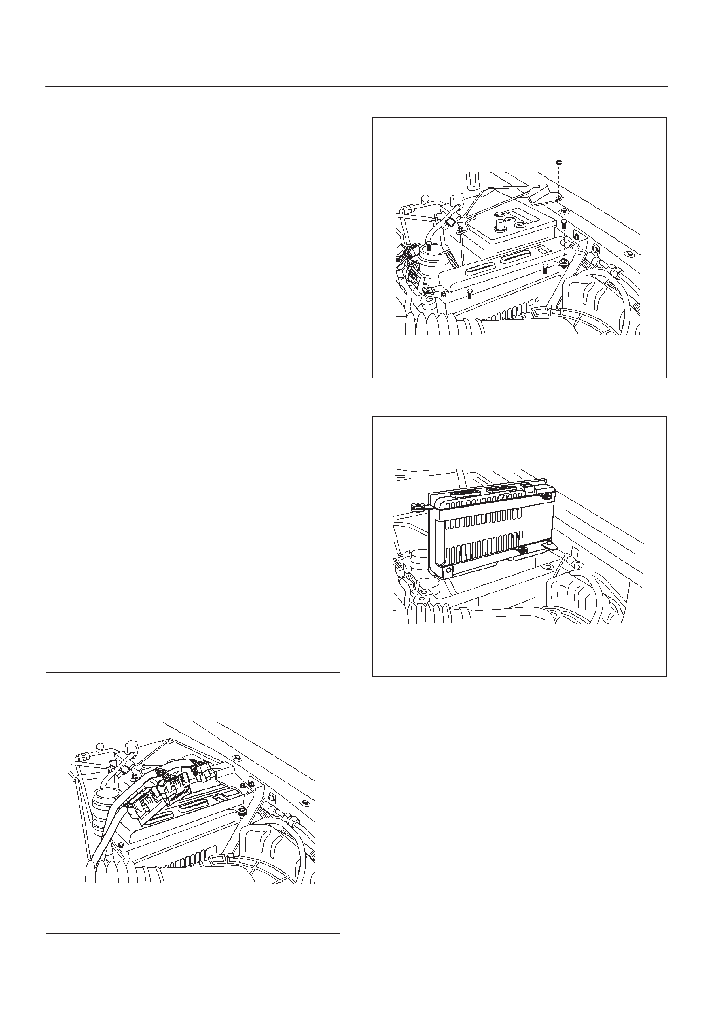
damage, therefore, it is important to use care when
handling and testing electronic components.
NOTE:To prevent possible Electrostatic Discharge
damage, follow these guidelines:
DDo not touch the control module connector pins or
soldered components on the control module circuit
board.
DDo not open the replacement part package until the
part is ready to be installed.
DBefore removing the part from the package, ground
the package to a known good ground on the vehicle.
DIf the part has been handled while sliding across the
seat, or while sitting down from a standing position, or
while walking a distance, touch a known good ground
before installing the part.
NOTE:To prevent internal ECM damage, the ignition
must be in the “OFF” position in order to disconnect or
reconnect power to the ECM (for example: battery cable,
ECM pigtail, ECM fuse, jumper cables, etc.).
IMPORTANT:When replacing the production ECM
with a service ECM, it is important to transfer the
broadcast code and production ECM number to the
service ECM label. This will allow positive identification of
ECM parts throughout the service life of the vehicle. Do
not record this information on the metal ECM cover.
IMPORTANT:The ignition should always be in the
“OFF” position in order to install or remove the ECM
connectors.
Service of the ECM should normally consist of either re-
placement of the ECM. If the diagnostic procedures call
for the ECM to be replaced, the ECM should be checked
first to ensure it is the correct part. If it is, remove the
faulty ECM and install the new service ECM.
DTC P0601 indicates the check sum error.
Removal Procedure
1.Disconnect the negative battery cable.
2.Disconnect the ECM connector.
035RW093
3.Remove the bolts ECM bracket and battery bracket.
035RW094
4.Remove the ECM.
035RW092
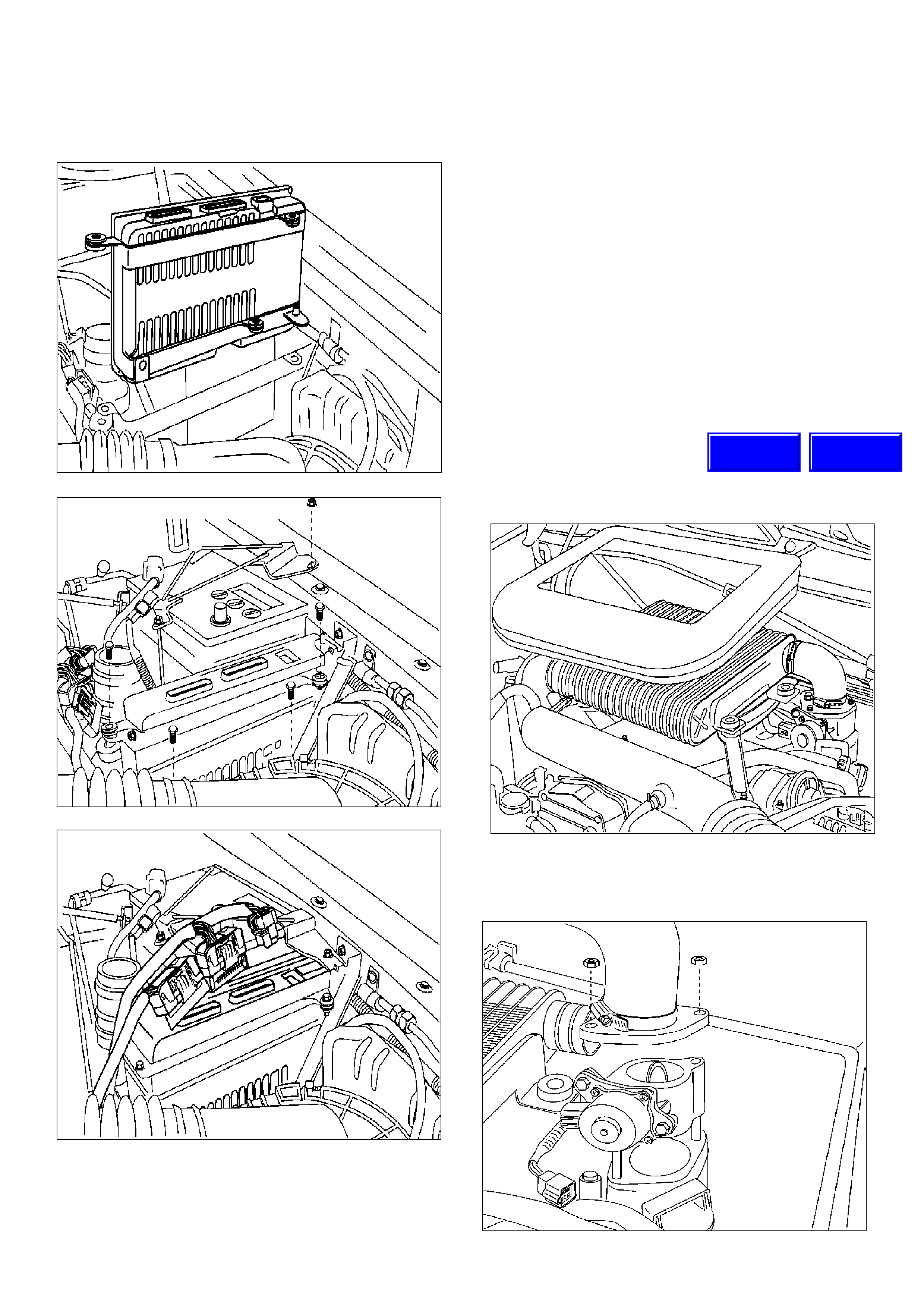
Installation Procedure
1.Install the ECM.
2. Install the bolts, ECM bracket and battery bracket.
3. Connect the ECM connector.
4. Connect the negative battery cable.
If the ECM is replaced, the new ECM will need to be
programmed.
EEPROM
General Description
The Electronically Erasable Programmable Read Only
Memory (EEPROM) is a permanent memory that is
physically soldered within the ECM. The EEPROM
contains program and calibration information that the
ECM needs to control powertrain operation.
Functional Check
1. Perform the On-Board Diagnostic System Check.
2. Start the engine and run for one minute.
3. Scan for DTCs using the Tech 2.
Intake Throttle Position (ITP)
Sensor
Removal Procedure
1. Disconnect the negative battery cable.
2. Remove the cover of the intercooler.
3. Remove the bolts and the left side bracket to the
intercooler.
4. Remove the air duct with bracket from the
intercooler.
5. Remove the throttle body from the intake manifold.
Techline
Techline
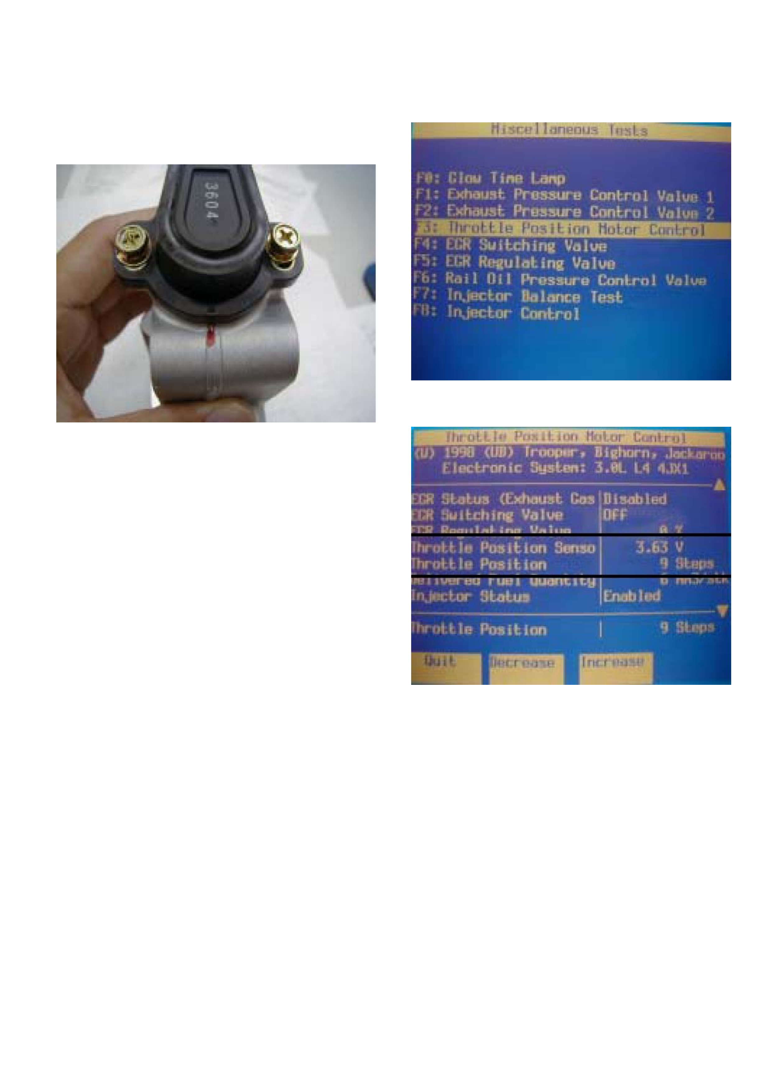
7. Next select the Throttle Position Motor Control
function.
6. Disconnect the ITP sensor electrical connector a nd
throttle motor control connector.
7. Before removing ITP sensor from the throttle body,
mark the throttle body with a marker pen.
8. Scroll down until throttle Position Sensor Output
Voltage and Throttle Position are displayed.
8. Remove the bolts and the ITP sensor from the
throttle body.
NOTE: Do not clean the ITP sensor by soaking it in
solvent. The sensor will be damaged as a result.
Function Check
Use a Tech 2 to check the ITP sensor output voltage
and compare this to the ITP sensor steps as follo ws:
1. Select Diagnostics
2. Select Vehicle Model Year
3. Select Vehicle Type
4. Select Powertrain
5. Select 3.0l 4JX1-TC
6. Select Miscellaneous Tests
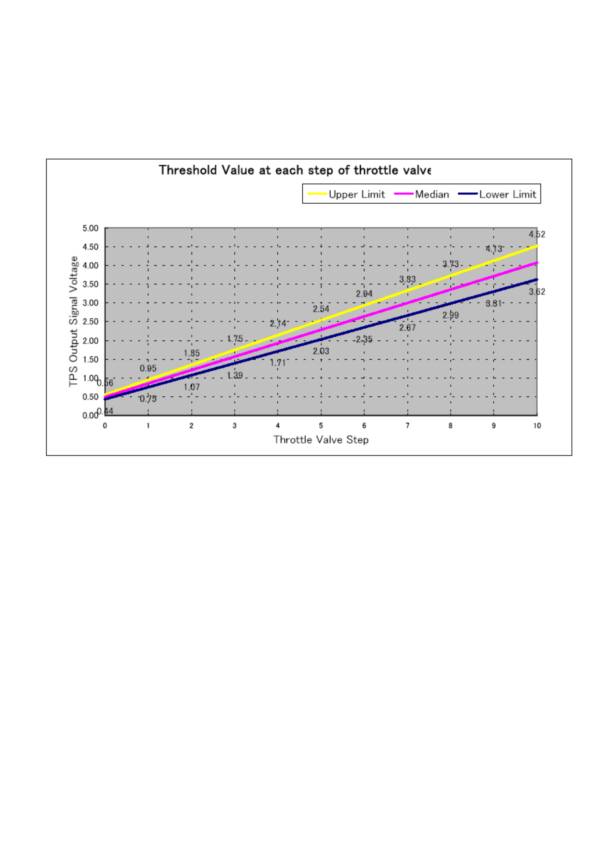
9. Verify the Throttle Position Sensor Output Voltage at
each Throttle Position Motor step position matches the
median of the threshold value range shown in the below
chart. If the values vary from the threshold value range,
adjust position of the ITP sensor so that the values suit
the criteria.
Installation Procedure
1. Install the ITP sensor on the throttle body with the
bolts.
2. Install the throttle body to the intake manifold and the
air duct with bracket between throttle body and
intercooler.
Torque: 20 N´m (14 Ib ft)
3. Connect the ITP sensor electrical connector and
throttle motor control connector.
4. Install the bracket to the intercooler.
5. Install the cover of intercooler.
6. Install the negative battery cable.
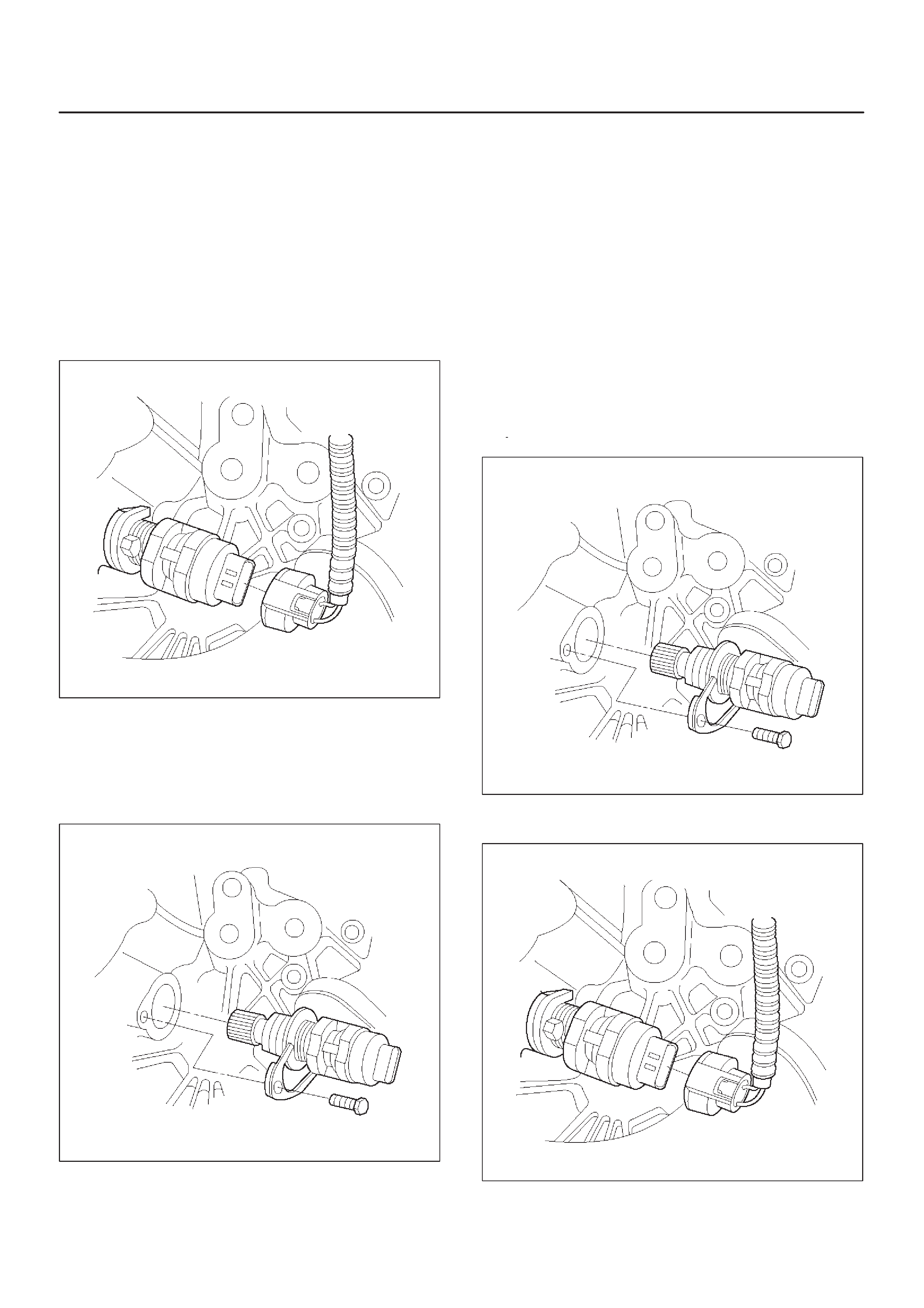
Vehicle Speed Sensor (VSS)
Removal Procedure
CAUTION:The VSS is located on the right side of
the transfer case just ahead of the rear propeller
shaft and very close to the exhaust pipes. Be sure
that the exhaust pipes are cool enough to touch
before trying to remove the VSS. If the pipes are hot,
you could be burned.
1.Disconnect the negative battery cable.
2.Disconnect the VSS electrical connector.
TS23748
3.Remove the bolt and the clamp securing the VSS in
place.
IMPORTANT:Have a container ready to catch any fluid
that leaks out when the VSS is removed from the transfer
case.
TS23780
4.Remove the VSS from the transfer case by wiggling it
slightly and pulling it straight out.
Inspection Procedure
1.Inspect the electrical connector for signs of corrosion
or warping. Replace the VSS if the electrical
connector is corroded or warped.
2.Inspect the VSS driven gear for chips, breaks, or worn
condition. Replace the VSS if the driven gear is
chipped, broken or worn.
3.Inspect the O-ring for wear, nicks, tears, or
looseness. Replace the O-ring if necessary.
Installation Procedure
1.Install the VSS in the transfer case with the notch for
the connector facing the rear.
2.Secure the VSS in place with the clamp and the bolt.
Tighten
DTighten the bolt to 16 N·m (12 lb ft.).
TS23780
3.Connect the VSS electrical connector.
TS23748
4.Check the transfer case oil level. Add fluid if
necessary.
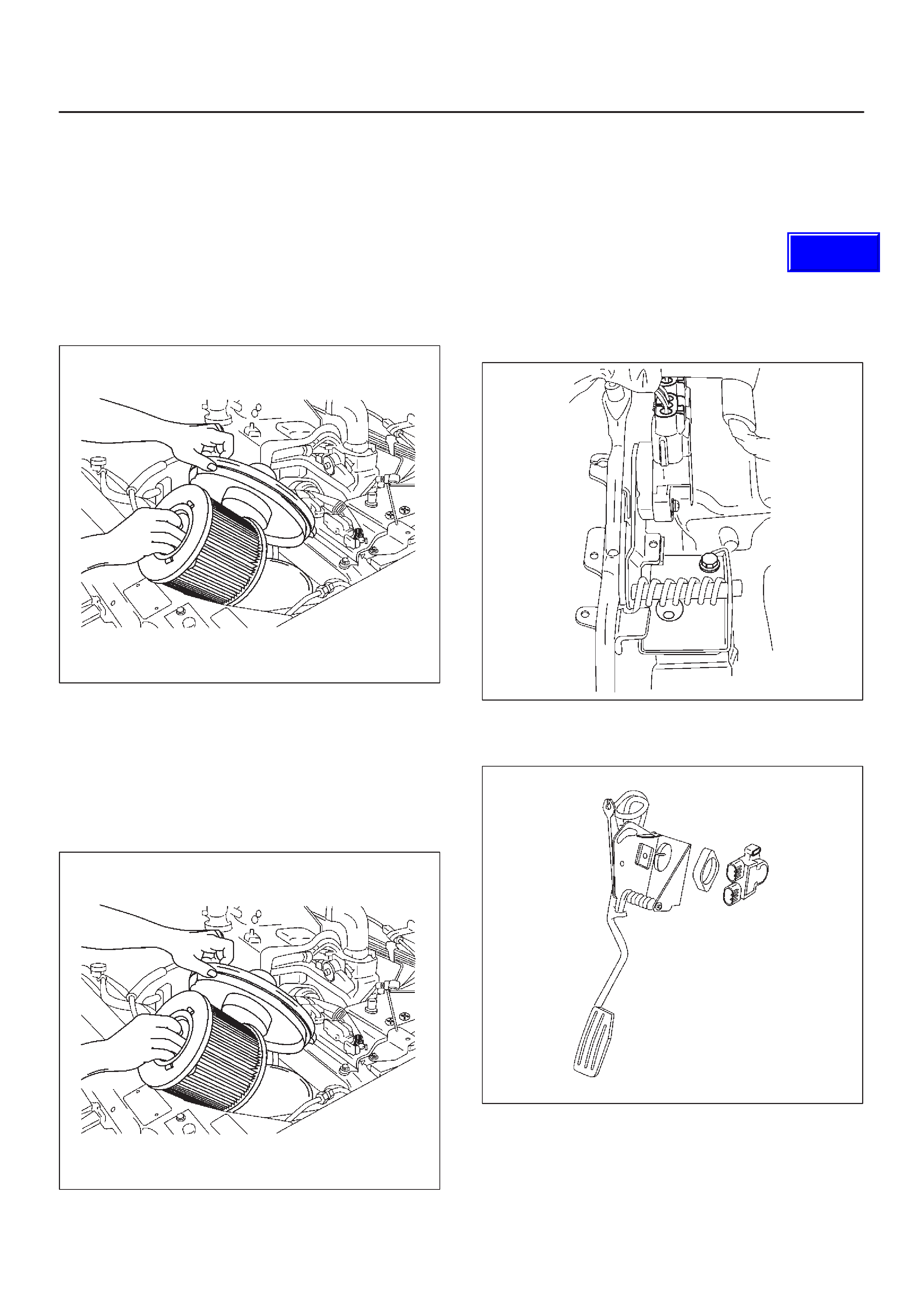
5.Connect the negative battery cable.
Air Cleaner/Air Filter
Removal Procedure
1.Loosen the clamp between the air cleaner lid and the
duct.
2.Release the four latches securing the lid to the air
cleaner housing.
3.Remove the air cleaner lid.
4.Remove the air filter element.
035RW074
5.Remove the retaining bolts and the air cleaner
housing from the vehicle.
Installation Procedure
1.Install the air cleaner housing in the vehicle with the
retaining bolts.
2.Install the air filter element in the air cleaner housing.
035RW074
3.Install the air cleaner lid on the air duct and the air
cleaner housing.
4.Tighten the clamp and secure the four latches
between the lid and the air cleaner housing.
Accel Position (AP) Sensor
Removal Procedure
1.Disconnect the negative battery cable.
2.Disconnect the electrical connector to the AP sensor .
3.Remove the bolts and the accelerator pedal
assembly from the bulkhead.
035RW060
4.Remove the bolts and AP sensor from the accelerator
pedal assembly.
035RW066
Techline
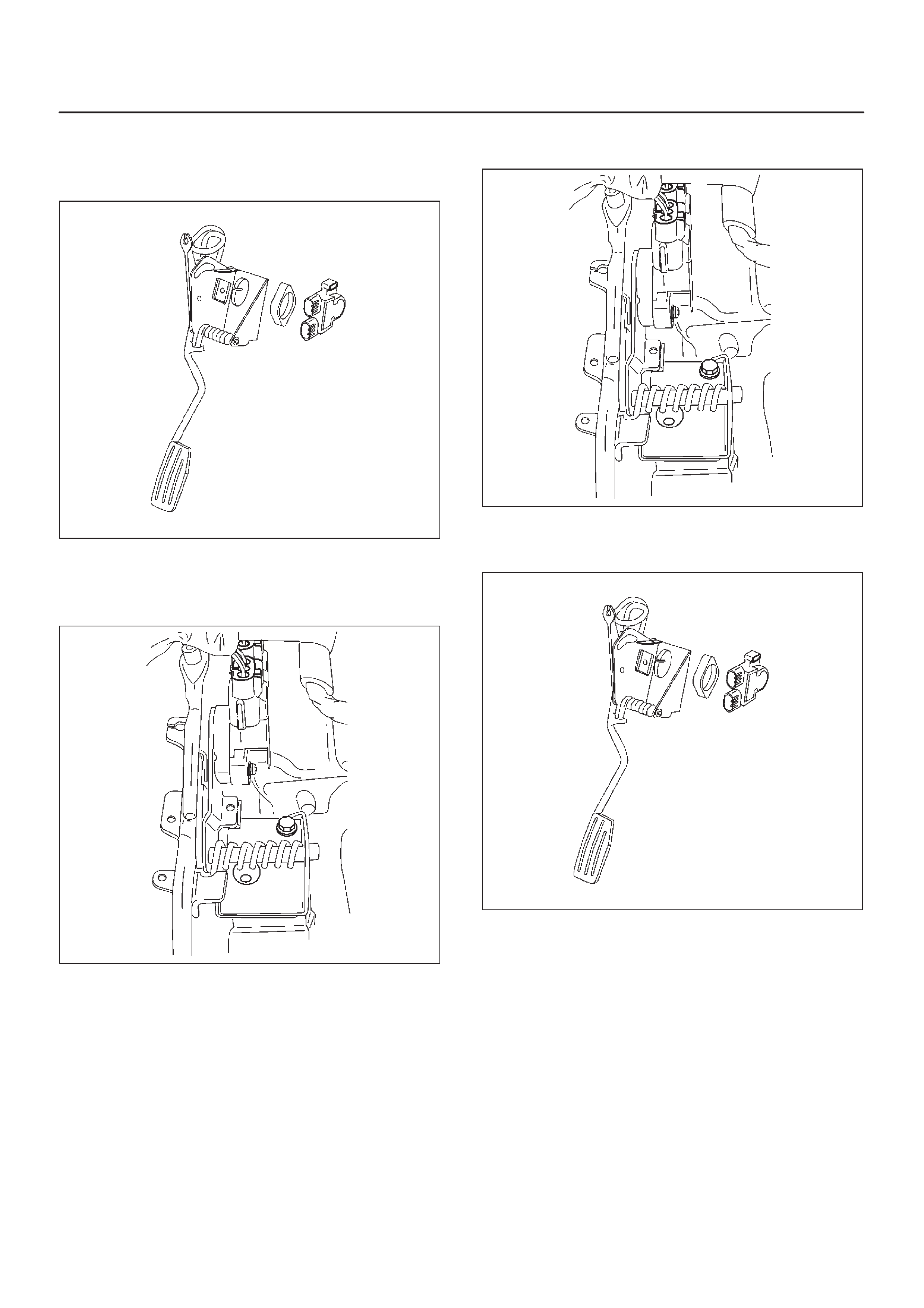
Installation Procedure
1.Install the AP sensor to the accelerator pedal
assembly.
035RW066
2.Install the accelerator pedal assembly to the
bulkhead.
3.Connect the electrical connector to the AP sensor.
035RW060
4.Connect the negative battery cable.
Accelerator Pedal Replacement
Removal Procedure
1.Disconnect the negative battery cable.
2.Disconnect the electrical connector to the AP sensor .
3.Remove the bolts and the accelerator pedal
assembly from the bulkhead.
035RW060
4.Remove the bolts and AP sensor from the accelerator
pedal assembly.
035RW066
Installation Procedure
1.Install the AP sensor to the accelerator pedal
assembly.
2.Install the accelerator pedal assembly to the
bulkhead.
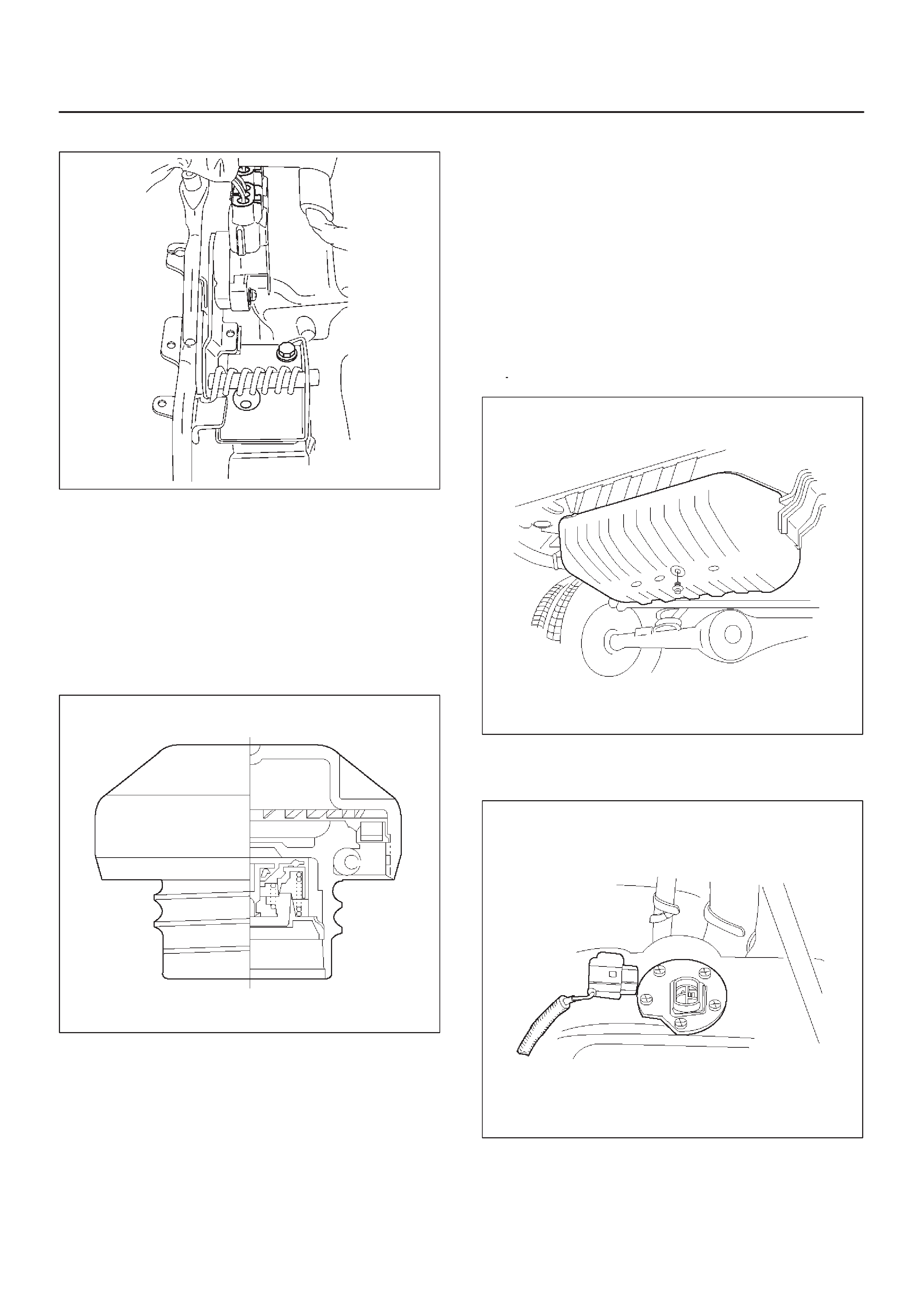
3.Connect the electrical connector to the AP sensor.
035RW060
4.Connect the negative battery cable.
Fuel Filter Cap
General Description
The fuel filler cap includes a vacuum valve and a pressure
valve.
If high vacuum or high pressure occurs in the fuel tank,
each valve works to adjust the pressure in order to
prevent damage to the tank at the EGR valve.
TS23767
Inspection Procedure
NOTE:Replace the fuel filler cap with the same type of
filler cap that was originally installed on the vehicle.
DCheck the seal ring in the filler cap for any abnormality
and for seal condition.
DReplace the filler cap if any abnormality is found.
Fuel Filter
Removal and Installation Procedure
Refer to the Engine fuel in the 4JX1 Engine section.
Fuel Gauge Unit
Removal Procedure
1.Disconnect the negative battery cable.
2.Loosen the fuel filler cap.
3.Drain the fuel from the tank.
Tighten
DTighten the drain plug to 20 N·m (14 lb ft.).
TS22907
4.Disconnect the wiring connector from the fuel gauge
unit.
TS23771
5.Remove the fuel gauge unit retaining screws.
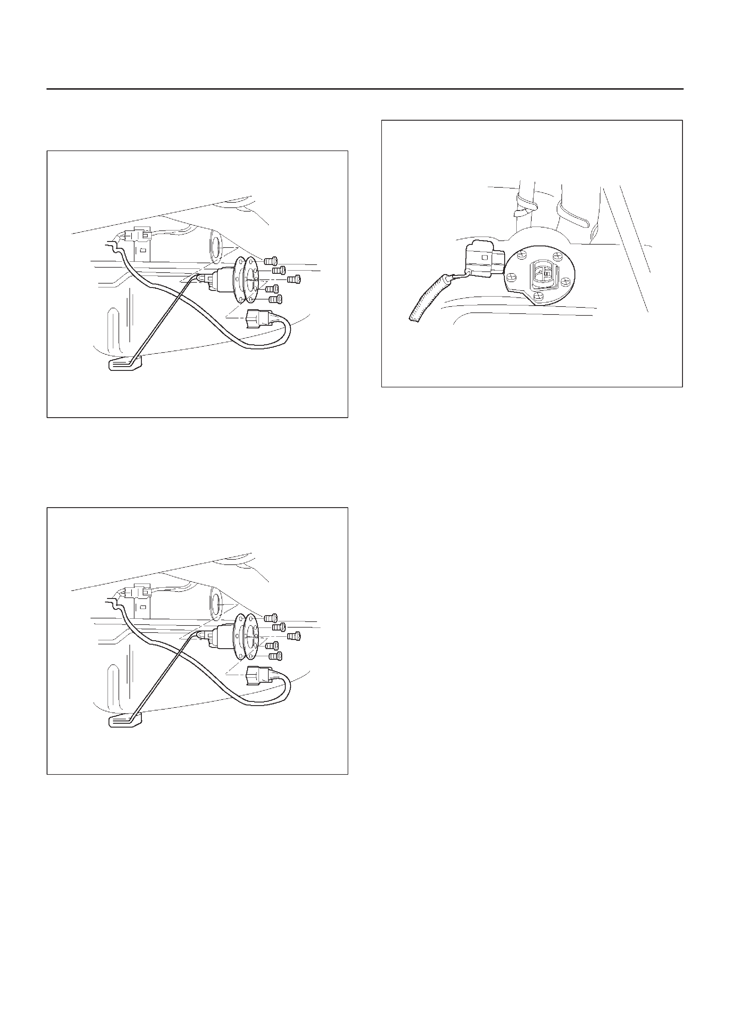
6.Remove the fuel gauge unit.
DCover or plug the fuel tank to prevent dust, dirt, or
debris from entering the tank.
TS22911
Installation Procedure
1.Install the fuel gauge unit.
2.Install the fuel gauge unit retaining screws.
TS22911
3.Connect the wiring connector to the fuel gauge unit.
TS23771
4.Fill the fuel tank with fuel.
DTighten the fuel filler cap.
DCheck for leaks at the fuel gauge unit gasket.
5.Connect the negative battery cable.
Fuel Injectors
Removal and Installation Procedure
Refer to Engine Fuel in 4JX1 Engine Section.
Fuel Temperature Sensor
Removal Procedure
CAUTION:To reduce the risk of fire and personal
injury, it is necessary to relieve the fuel system
pressure before servicing the fuel system
components.
CAUTION:After relieving the system pressure, a
small amount of fuel may be released when servicing
fuel lines or connections. Reduce the chance of
personal injury by covering the fuel line fittings with
a shop towel before disconnecting the fittings. The
towels will absorb any fuel that may leak out. When
the disconnect is completed, place the towel in an
approved container.
1.Disconnect the negative battery cable.
2.Remove the intercooler assembly.
3.Remove the cylinder head. Refer to engine
mechanical section.
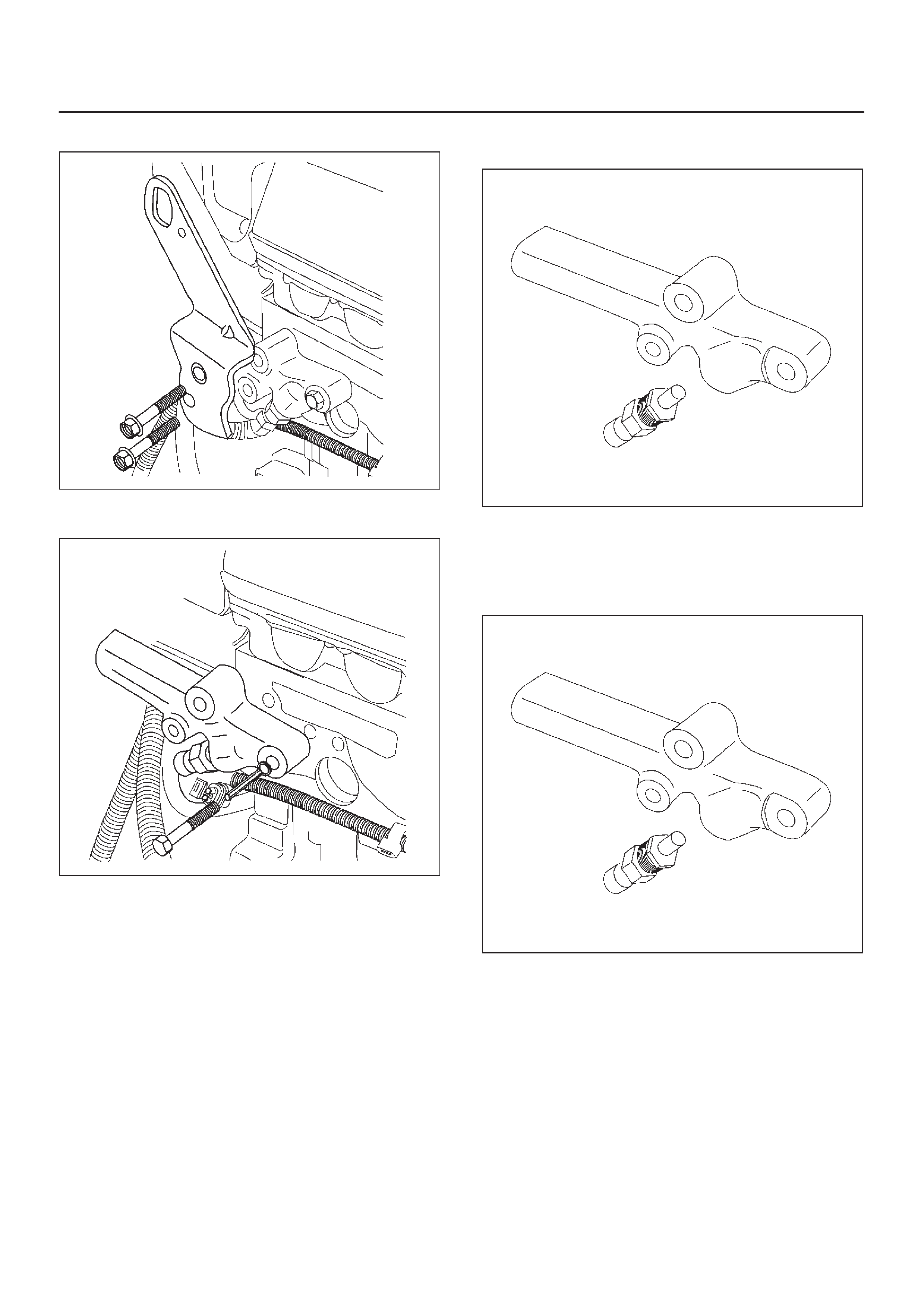
4.Remove the rear side engine hanger.
035RW070
5.Remove the fuel return adapter.
035RW069
6.Remove the fuel pressure sensor from the fuel return
adapter.
035RW068
Installation Procedure
1.Install the fuel pressure sensor in the fuel return
adapter.
035RW068
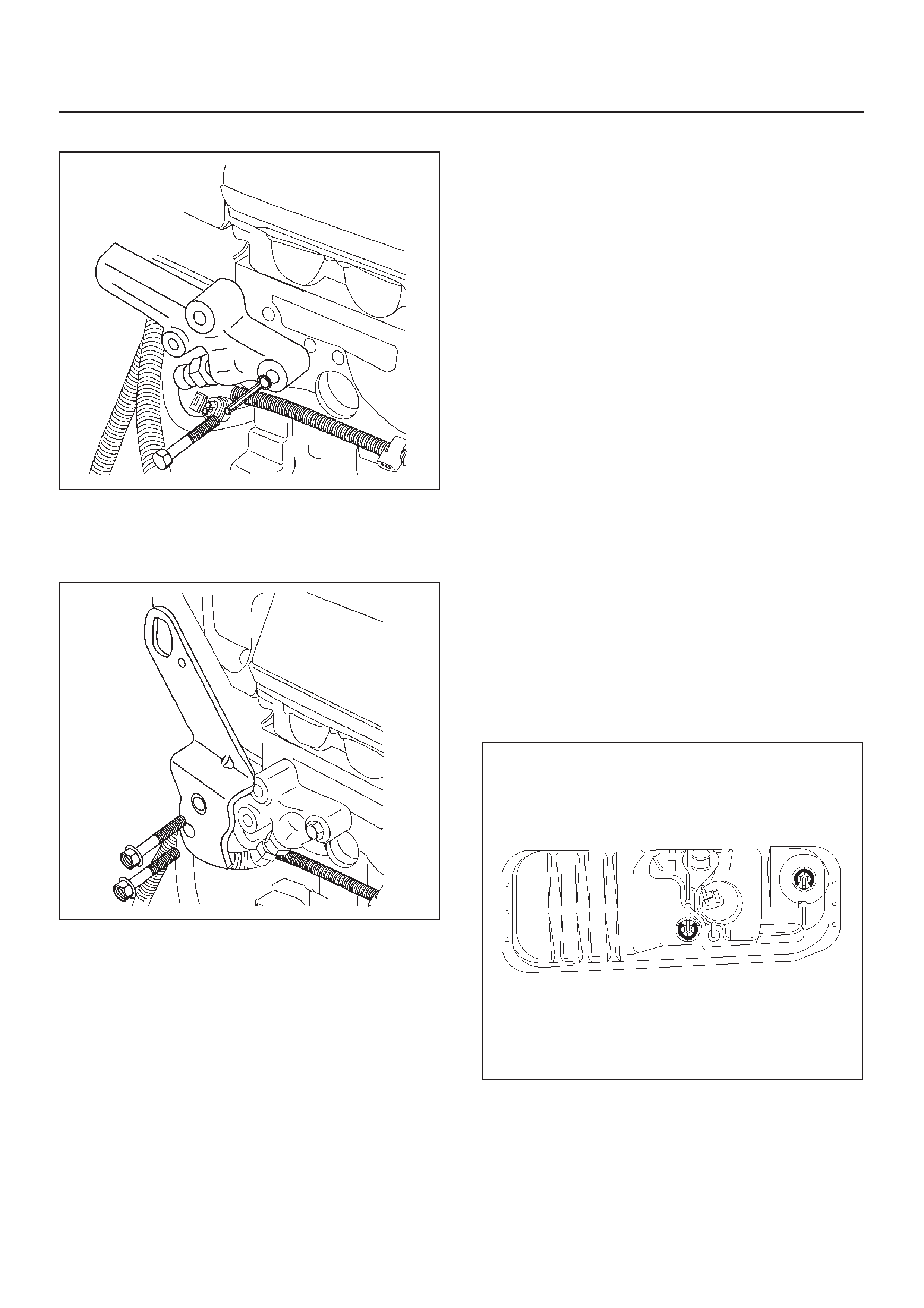
2.Install the fuel return adapter.
035RW069
3.Install the rear side engine hanger. Tighten the rear
side engine hanger fixing bolts to specified torque.
Torque: 19 N·m (14 lb ft)
035RW070
4.Install the cylinder head. Refer to engine mechanical
section.
5.Install the intercooler assembly.
6.Connect the negative battery cable.
Rail Pressure (RP) Sensor
Removal Procedure
1.Disconnect the negative battery cable.
2.Remove the air cleaner cover and air duct.
3.Remove the intercooler assembly.
4.Remove the injector oil pipe.
5.Remove the intake throttle valve.
6.Remove the cylinder head cover noise inselation.
7.Remove the cylinder head cover.
8.Remove the RP sensor.
Installation Procedure
DRefer to the
RP Sensor Programming
.
1.Install the RP sensor.
2.Install the cylinder head cover.
3.Install the cylinder head cover noise inselation.
4.Install the intake throttle valve.
5.Install the injector oil pipe.
6.Install the intercooler assembly and tighten
intercooler assembly fixing bolts to specified torque.
Torque: 20 N·m (14 lb ft)
7.Install the air cleaner cover and air duct.
8.Connect the negative battery cable.
Fuel Tank
Removal Procedure
Refer to
Engine Fuel in 4JX1 Engine section.
060RW068
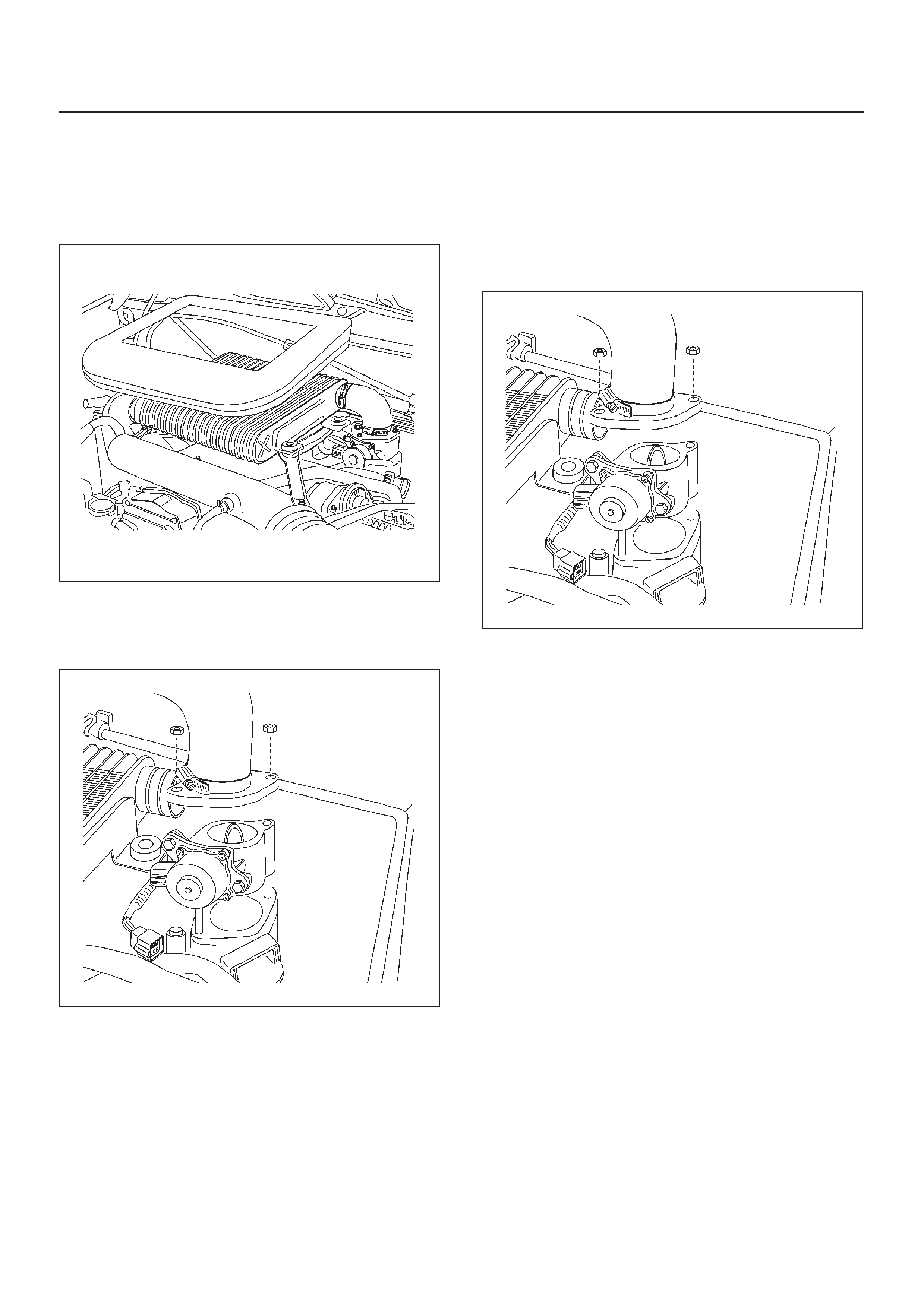
Throttle Body (TB)
Removal Procedure
1.Disconnect the negative battery cable.
2.Remove the cover of the intercooler.
035RW051
3.Remove the bolts and the left side bracket to the
intercooler.
4.Remove the air duct with bracket from the intercooler.
035RW086
5.Remove the throttle body assembly from the intake
manifold.
6.Disconnect the ITP sensor electrical connector.
Installation Procedure
NOTE: Do not use solvent of any type when you clean the
gasket surfaces on the intake manifold and the throttle
body assembly. The gasket surfaces and the throttle body
assembly may be damaged as a result.
DIf the throttle body gasket needs to be replaced,
remove any gasket material that may be stuck to the
mating surfaces of the manifold.
DDo not leave any scratches in the aluminum casting.
1.Install the throttle body assembly to the intake
manifold and the air duct with bracket between
throttle body and intercooler.
Torque: 20 N·m (14 Ib ft)
035RW086
2.Connect the ITP sensor electrical connector and
throttle motor control connector.
3.Install the bracket to the intercooler.
4.Install the cover of intercooler.
5.Connect the negative battery cable.
Air Conditioning (A/C) Relay
Removal Procedure
1.Remove the fuse and relay box cover from under the
hood.
2.Consult the diagram on the cover to determine which
is the correct relay.
3.Pull the relay straight up and out of the fuse and relay
box.
Installation Procedure
1.Insert the relay into the correct place in the fuse and
relay box with the catch slot facing forward.
2.Press down until the catch engages.
DAn audible “click” will be heard.
3.Install the fuse and relay box cover.
Exhaust Gas Recirculation
(EGR) Vacuum Switch Valve
(VSV)
Removal Procedure
1.Disconnect the negative battery cable.
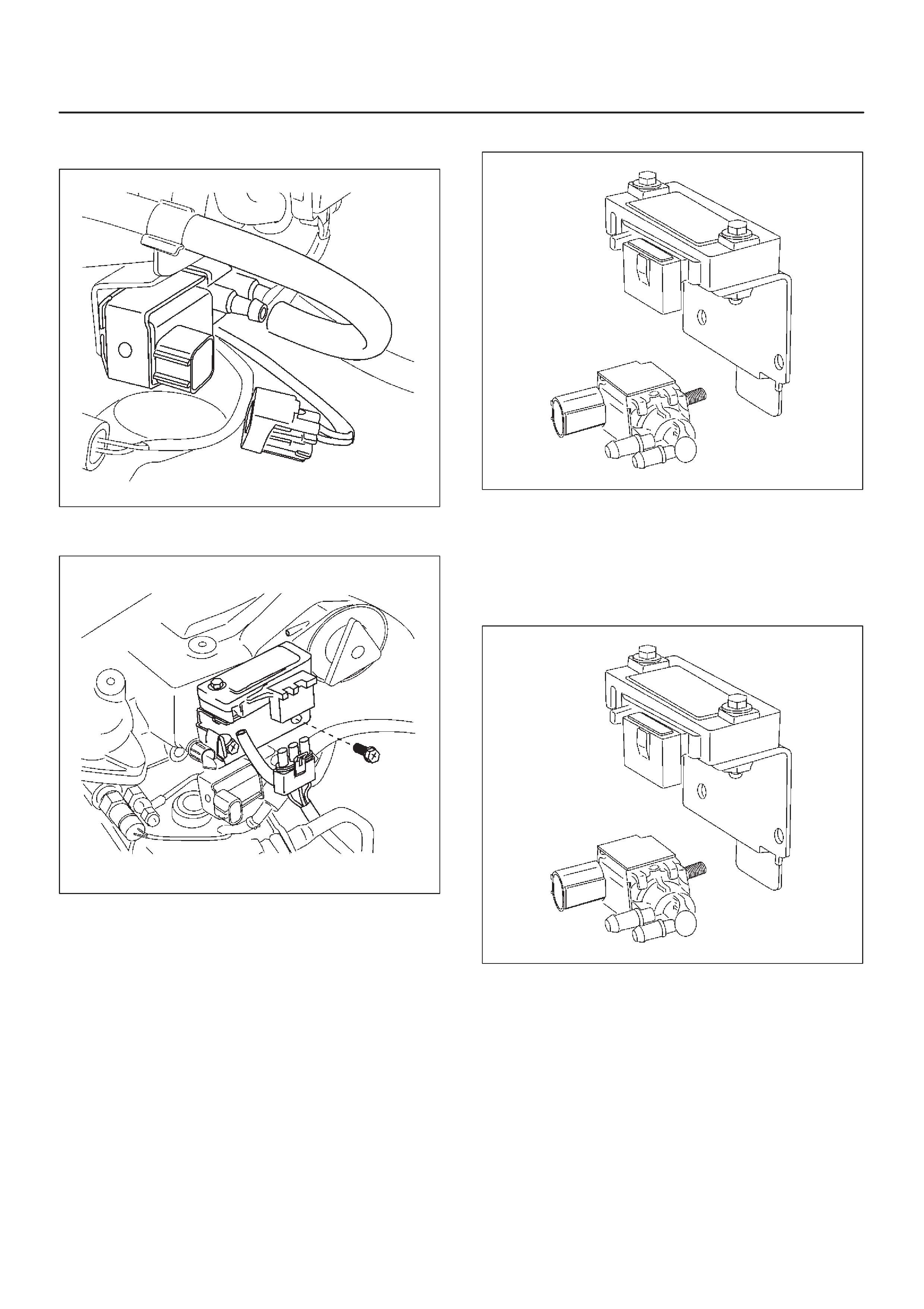
2.Disconnect the EGR VSV connector and vacuum
hose from the EGR VSV.
035RW063
3.Remove the MAP sensor assembly and EGR VSV.
035RW067
4.Remove the EGR VSV from the MAP sensor bracket.
035RW062
Installation Procedure
1.Install the EGR VSV and tighten nut to specified
torque.
Torque: 8 N·m (69 lb in)
035RW062
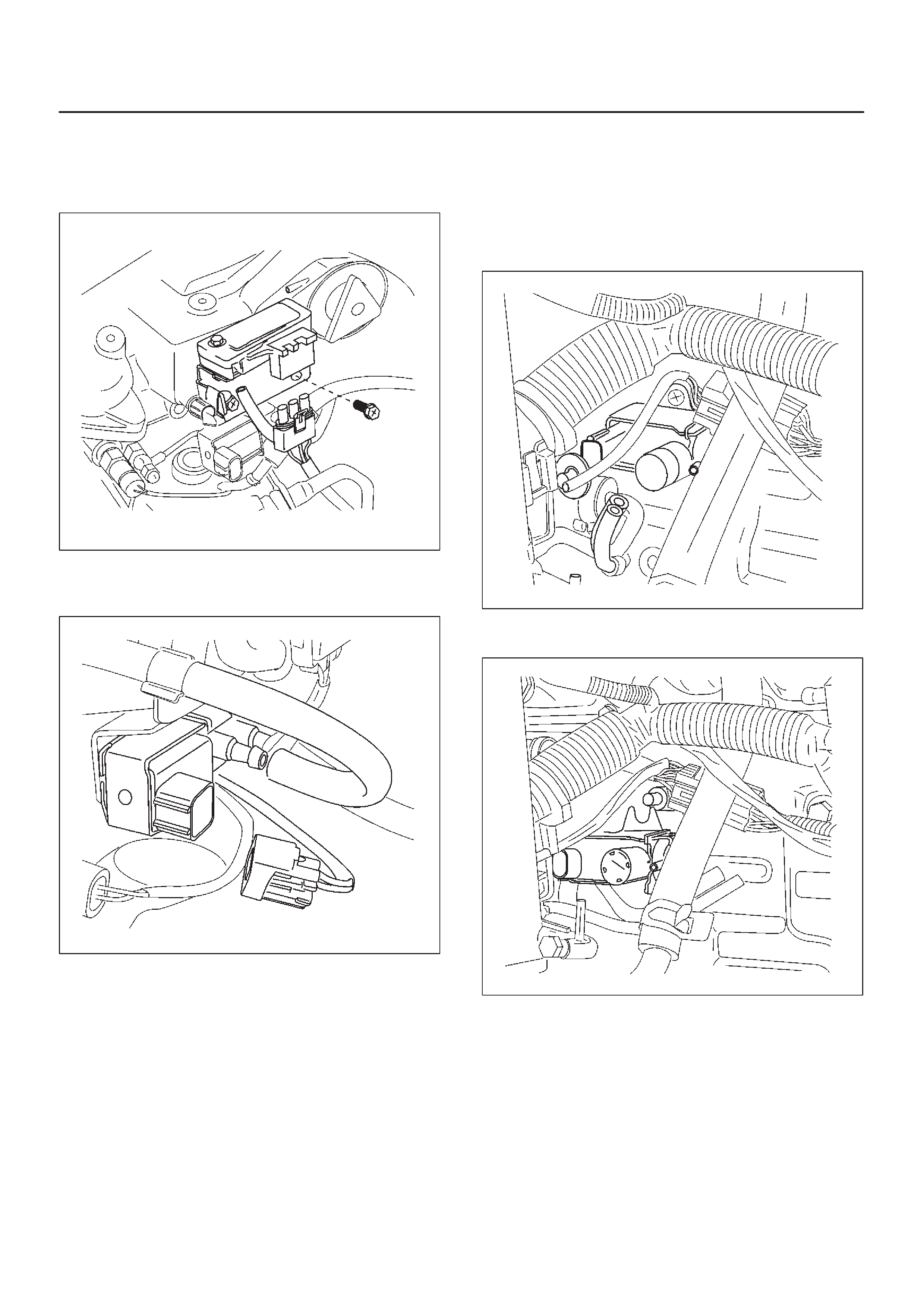
2.Install the MAP sensor assembly and EGR VSV and
tighten MAP sensor bracket fixing bolts specified
torque.
Torque: 9 N·m (78 lb in)
035RW067
3.Connect the EGR VSV connector and vacuum hose
in the EGR VSV.
035RW063
4.Connect the negative battery cable.
Electronic Vacuum Regurating
Valve (EVRV)
Removal Procedure
1.Disconnect the negative battery cable.
2.Disconnect the EVRV hose and the EVRV connector .
035RW065
3.Remove the EVRV.
035RW064
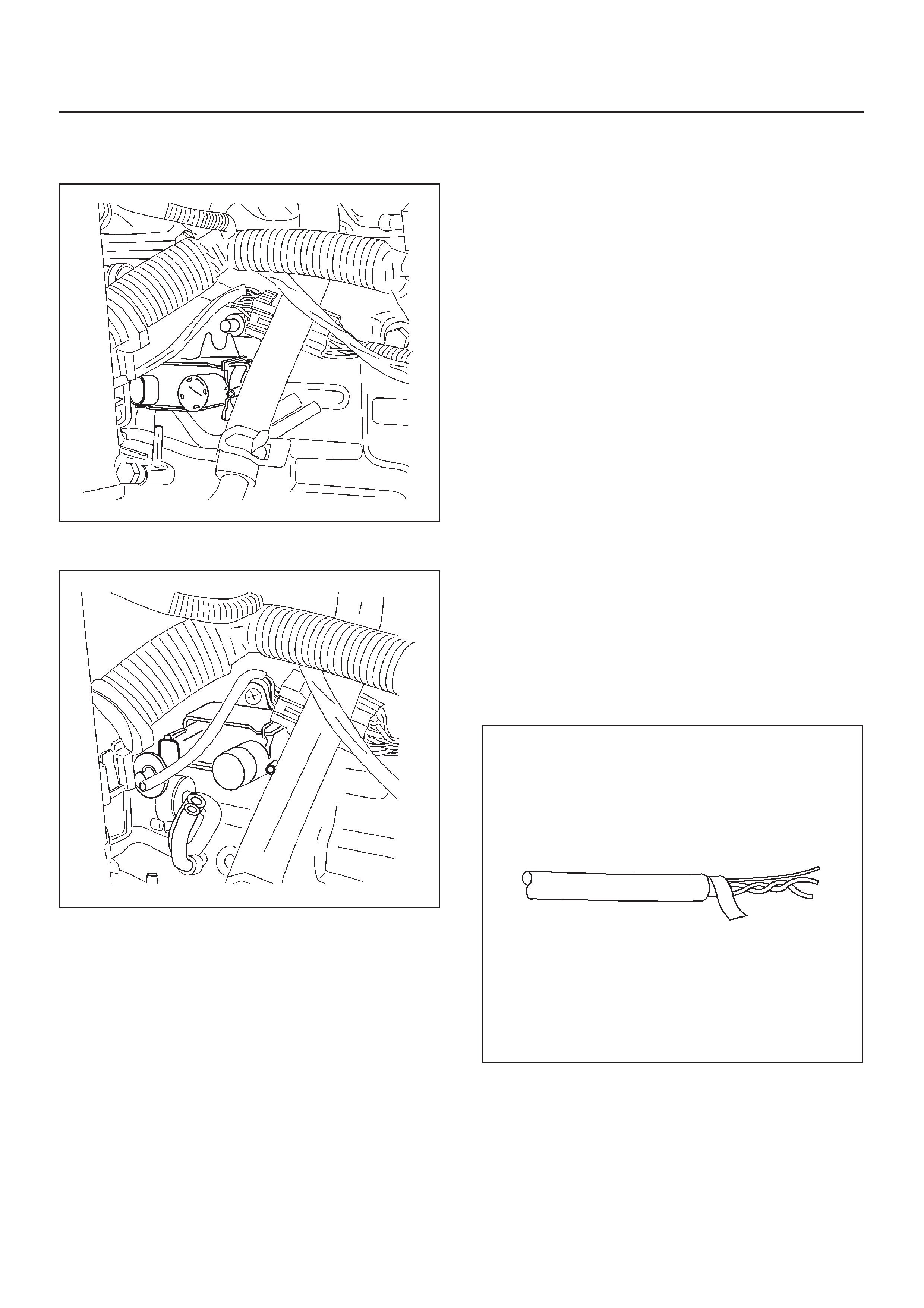
Installation Procedure
1.Install the EVRV.
035RW064
2.Connect the EVRV hose and the EVRV connector.
035RW065
3.Connect the negative battery cable.
Wiring and Connectors
Wiring Harness Service
The ECM harness electrically connects the ECM to the
various solenoids, switches and sensors in the vehicle
engine compartment and passenger compartment.
Replace wire harnesses with the proper part number
replacement.
Because of the low amperage and voltage levels utilized
in powertrain control systems, it is essential that all wiring
in environmentally exposed areas be repaired with crimp
and seal splice sleeves.
The following wire harness repair information is intended
as a general guideline only. Refer to
Chassis Electrical
for
all wire harness repair procedures.
Connectors and Terminals
Use care when probing a connector and when replacing
terminals. It is possible to short between opposite
terminals. Damage to components could result. Always
use jumper wires between connectors for circuit
checking. NEVER probe through Weather-Pack seals.
Use an appropriate connector test adapter kit which
contains an assortment of flexible connectors used to
probe terminals during diagnosis. Use an appropriate
fuse remover and test tool for removing a fuse and to
adapt the fuse holder to a meter for diagnosis.
Open circuits are often difficult to locate by sight because
oxidation or terminal misalignment are hidden by the
connectors. Merely wiggling a connector on a sensor , or
in the wiring harness, may temporarily correct the open
circuit. Intermittent problems may also be caused by
oxidized or loose connections.
Be certain of the type of connector/terminal before
making any connector or terminal repair. Weather-Pack
and Com-Pack III terminals look similar , but are serviced
differently.
Wire Harness Repair: Twisted
Shielded Cable
Removal Procedure
1.Remove the outer jacket.
2.Unwrap the aluminum/mylar tape. Do not remove the
mylar.
047
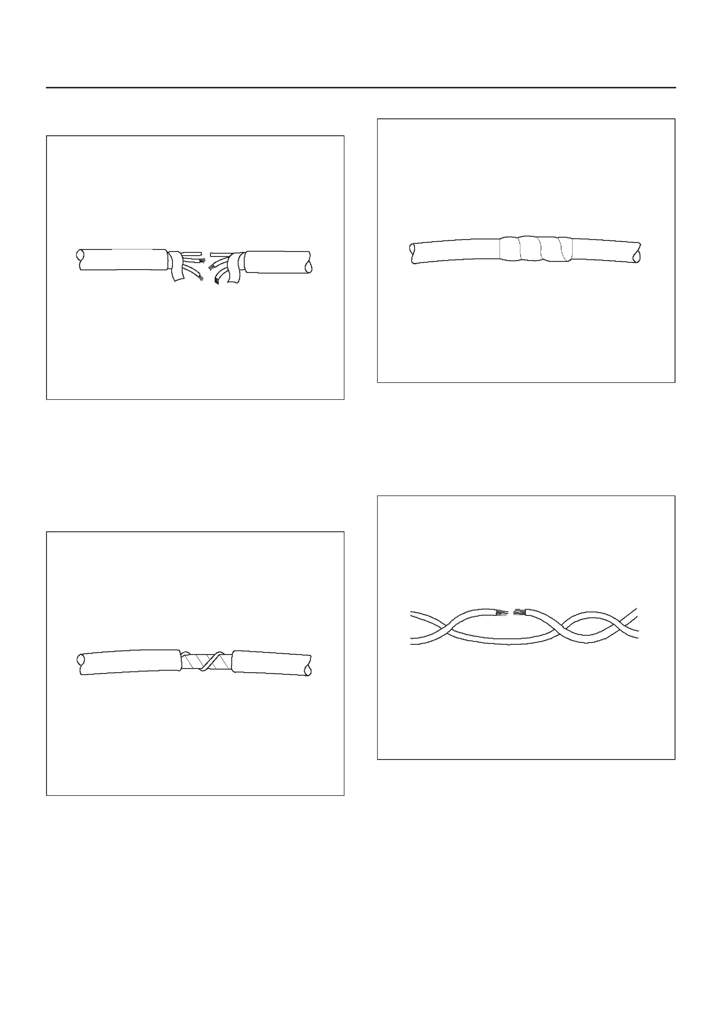
3.Untwist the conductors.
4.Strip the insulation as necessary.
048
Installation Procedure
1.Splice the wires using splice clips and rosin core
solder.
2.Wrap each splice to insulate.
3.Wrap the splice with mylar and with the drain
(uninsulated) wire.
049
4.Tape over the whole bundle to secure.
050
Twisted Leads
Removal Procedure
1.Locate the damaged wire.
2.Remove the insulation as required.
051
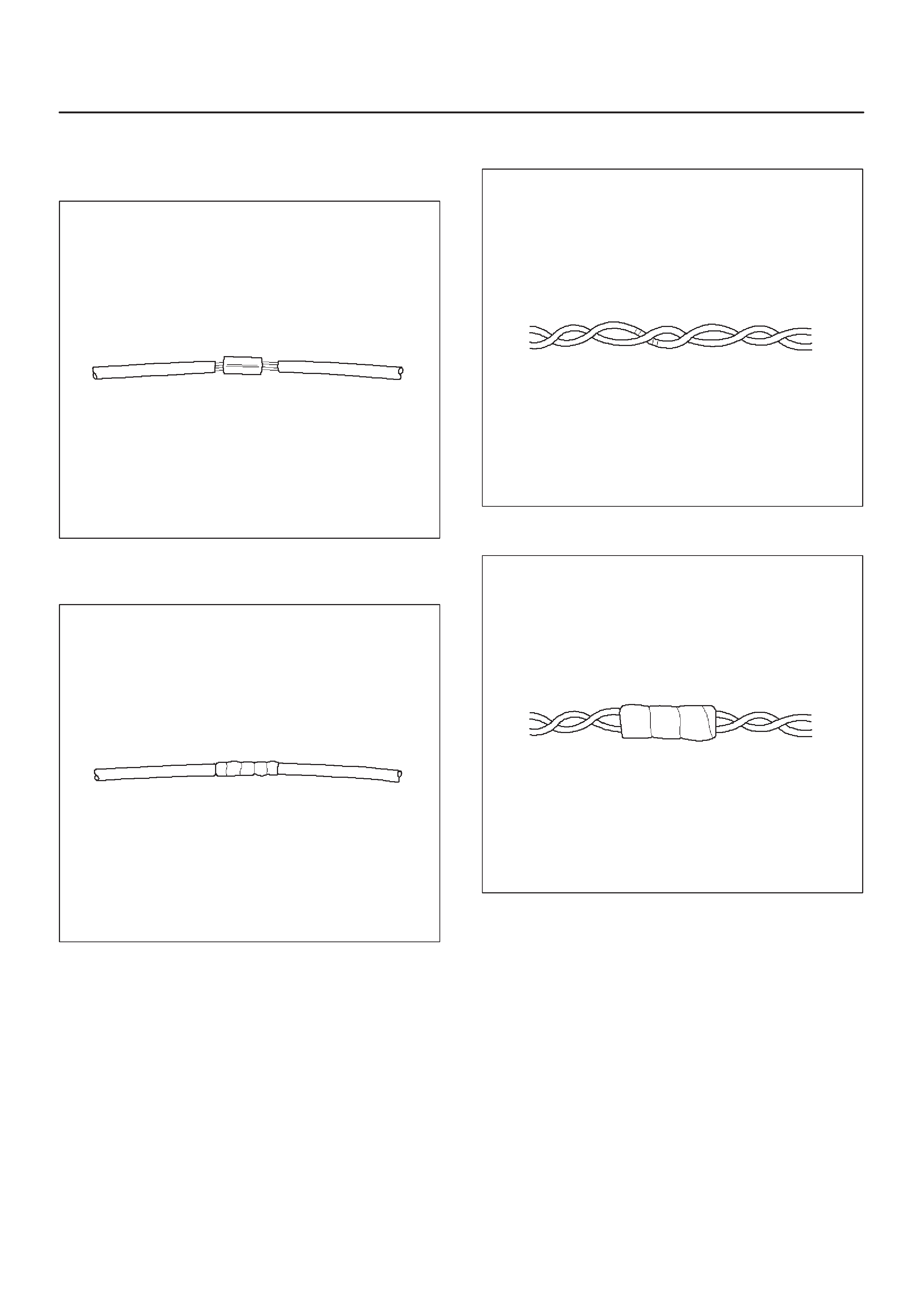
Installation Procedure
1.Use splice clips and rosin core solder in order to splice
the two wires together.
052
2.Cover the splice with tape in order to insulate it from
the other wires.
053
3.Twist the wires as they were before starting this
procedure.
054
4.Tape the wires with electrical tape. Hold in place.
055
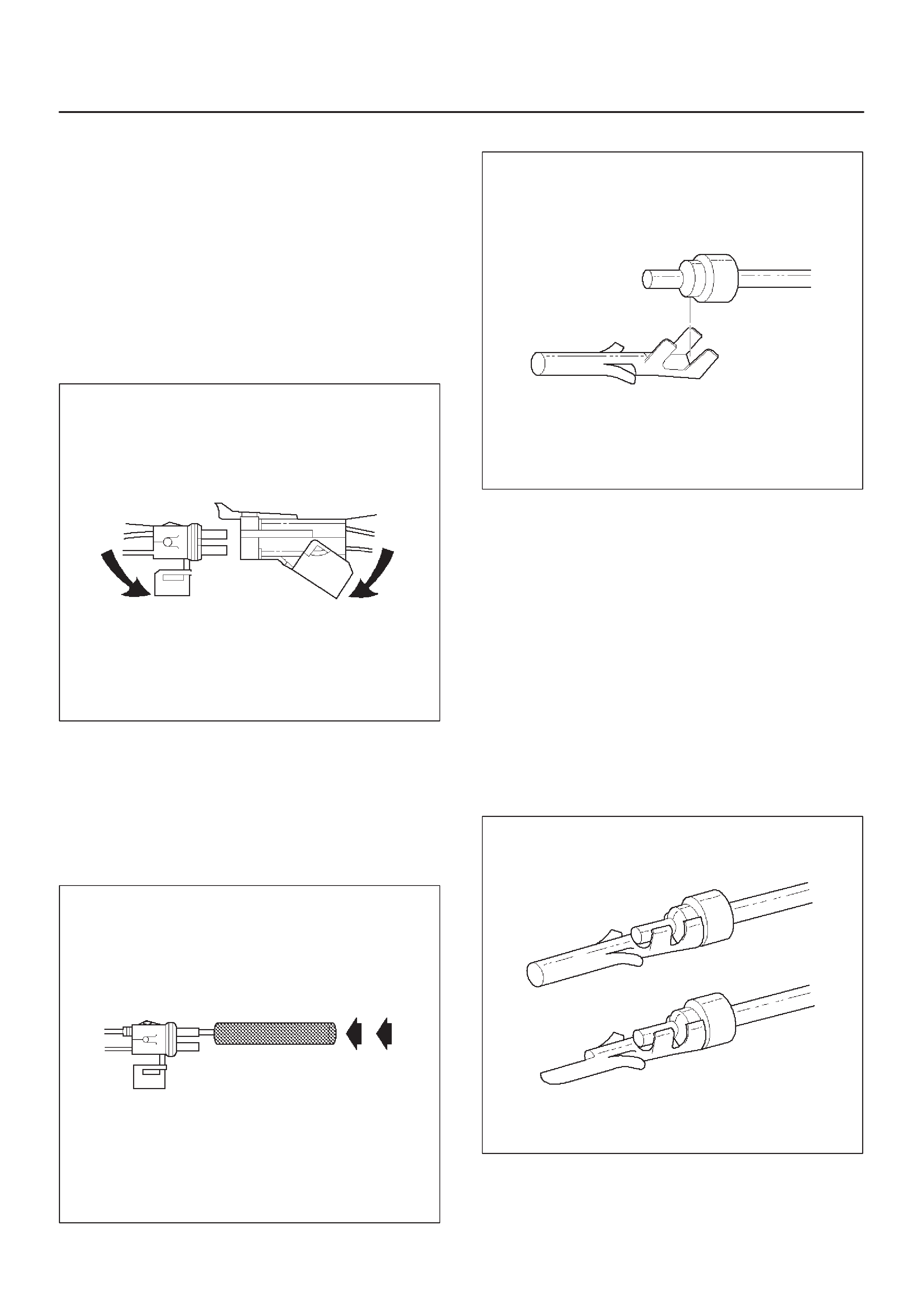
Weather-Pack Connector
Tools Required
5-8840-0388-0 Weather-Pack II Terminal Remover
Removal Procedure
A Weather-Pack connector can be identified by a rubber
seal at the rear of the connector. This engine room
connector protects against moisture and dirt, which could
from oxidation and deposits on the terminals. This
protection is important, because of the low voltage and
the low amperage found in the electronic systems.
1.Open the secondary lock hinge on the connector.
070
2.Use tool 5-8840-0388-0 or the equivalent to remove
the pin and the sleeve terminals. Push on
5-8840-0388-0 to release.
NOTE: Do the use an ordinary pick or the terminal may
be bent or deformed. Unlike standard blade terminals,
these terminals cannot be straightened after they have
been improperly bent.
071
3.Cut the wire immediately behind the cable seal.
072
Installation Procedure
Make certain the connectors are properly seated and all
of the sealing rings are in place when you reconnect the
leads. The secondary lock hinge provides a backup
locking feature for the connector. The secondary lock
hinge is used for added reliability. This flap should retain
the terminals even if the small terminal lock tangs are not
positioned properly.
Do not replace the Weather-Pack connections with
standard connections. Read the instructions provided
with the Weather-Pack connector and terminal packages.
1.Replace the terminal.
2.Slip the new seal onto the wire.
3.Strip 5 mm (0.2”) of insulation from the wire.
4.Crimp the terminal over the wire and the seal.
073
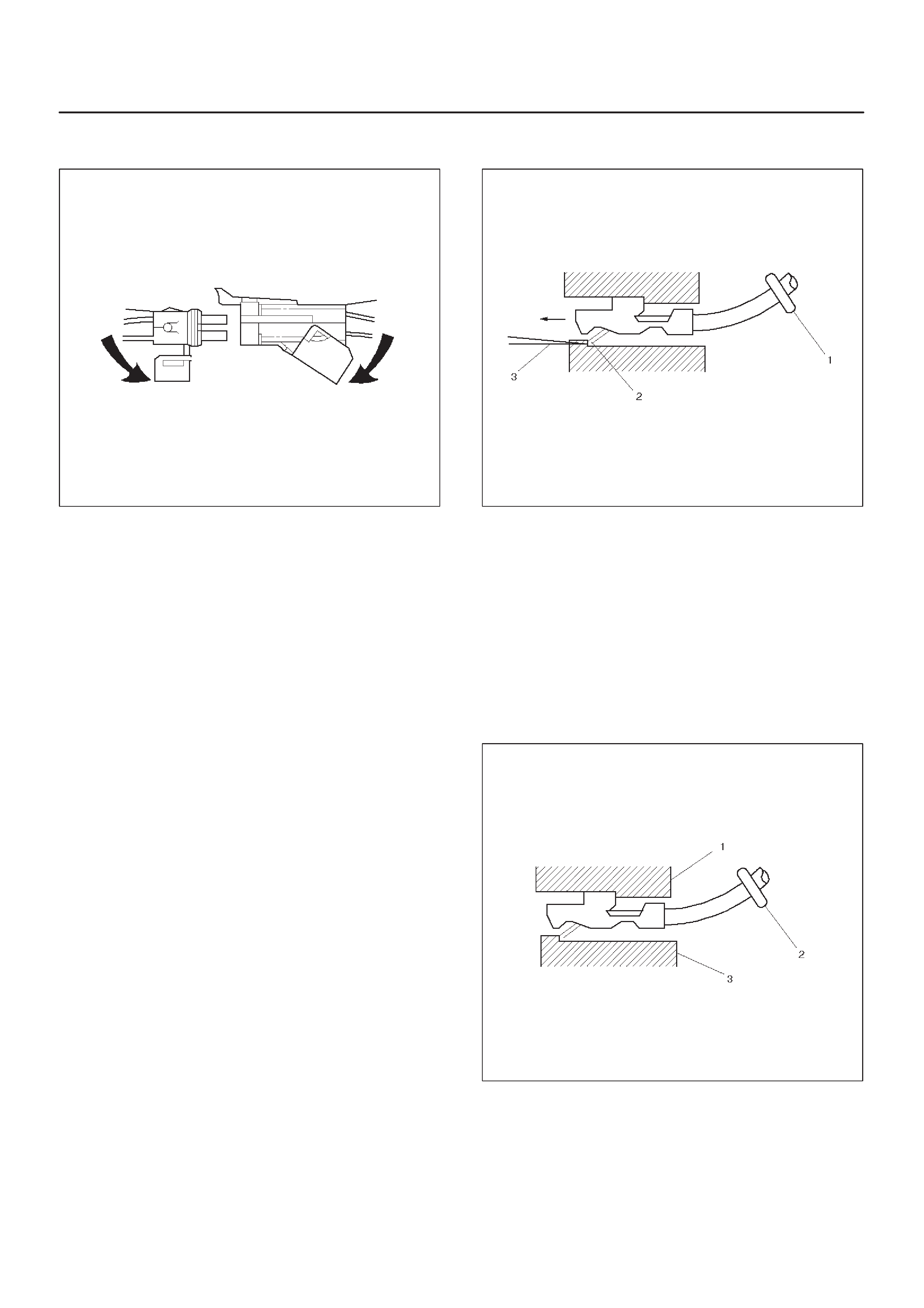
5.Push the terminal and the connector to engage the
locking tangs.
070
6.Close the secondary locking hinge.
Com-Pack III
General Information
The Com-Pack III terminal looks similar to some
Weather-Pack terminals. This terminal is not sealed and
is used where resistance to the environment is not
required. Use the standard method when repairing a
terminal. Do not use the Weather-Pack terminal tool
5-8840-0388-0 or equivalent. These will damage the
terminals. Metri-Pack
Tools Required
5-8840-0632-0 Terminal Remover
Removal Procedure
Some connectors use terminals called Metri-Pack Series
150. These may be used at the engine coolant
temperature (ECT) sensor.
1.Slide the seal (1) back on the wire.
2.Insert the 5-8840-0632-0 tool or equivalent (3) in
order to release the terminal locking tang (2).
060
3.Push the wire and the terminal out through the
connector. If you reuse the terminal, reshape the
locking tang.
Installation Procedure
Metri-Pack terminals are also referred to as “pull-to-seat”
terminals.
1.In order to install a terminal on a wire, the wire must be
inserted through the seal (2) and through the
connector (3).
2.The terminal (1) is then crimped onto the wire.
061
3.Then the terminal is pulled back into the connector to
seat it in place.
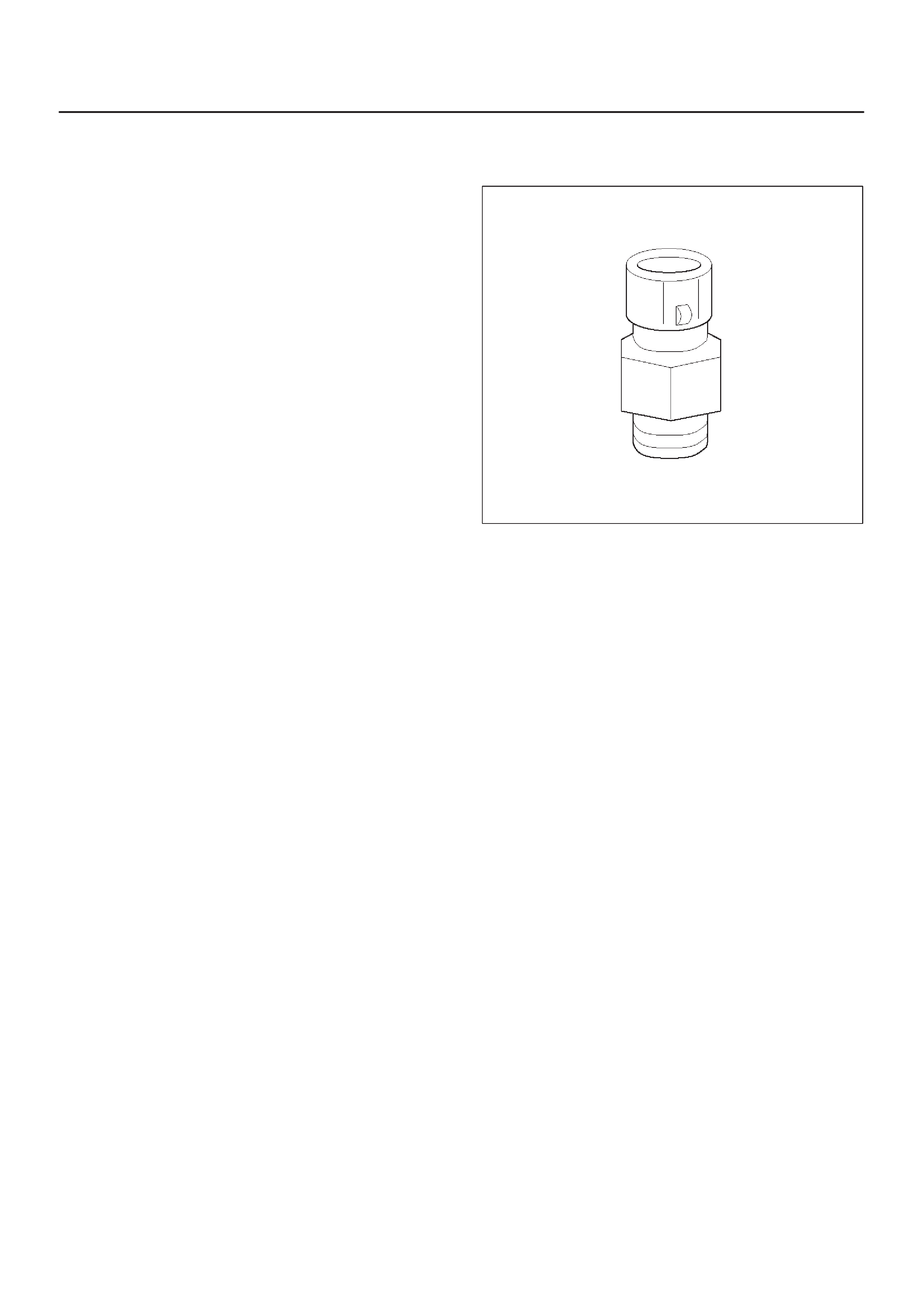
General Description
(ECM and Sensors)
57X Reference ECM Input
The engine control module (ECM) uses this signal from
the crankshaft position (CKP) sensor to calculate engine
RPM and crankshaft position at all engine speeds. The
ECM also uses the pulses on this circuit to initiate injector
pulses. If the ECM receives no pulses on this circuit, DTC
P0337 will set. The engine will not start and run without
using the 57X reference signal.
A/C Request Signal
This signal tells the ECM when the A/C mode is selected
at the A/C control head.
Crankshaft Position (CKP) Sensor
The crankshaft position (CKP) sensor provides a signal
used by the engine control module (ECM) to calculate the
ignition sequence. The CKP sensor initiates the 57X
reference pulses which the ECM uses to calculate RPM
and crankshaft position.
Camshaft Position (CMP) Sensor and
Signal
The camshaft position (CMP) sensor sends a CMP signal
to the ECM. The ECM uses this signal as a “cylinder
distinction” to trigger the injectors in the power order. If the
ECM detects an incorrect CMP signal while the engine is
running, DTC P0341 will set, and the ECM triggers the
injectors in the power order.
Refer to
DTC P0341
.
Engine Coolant Temperature (ECT) Sensor
The engine coolant temperature (ECT) sensor is a
thermistor (a resistor which changes value based on
temperature) mounted in the engine coolant stream. Low
coolant temperature produces a high resistance of
100,000 ohms at –40°C (–40°F). High temperature
causes a low resistance of 70 ohms at 130°C (266°F).
The ECM supplies a 5-volt signal to the ECT sensor
through resistors in the ECM and measures the voltage.
The signal voltage will be high when the engine is cold and
low when the engine is hot. By measuring the voltage, the
ECM calculates the engine coolant temperature. Engine
coolant temperature affects most of the systems that the
ECM controls.
The Tech 2 displays engine coolant temperature in
degrees. After engine start-up, the temperature should
rise steadily to about 85°C (185°F). It then stabilizes
when the thermostat opens. If the engine has not been
run for several hours (overnight), the engine coolant
temperature and intake air temperature displays should
be close to each other . A hard fault in the engine coolant
sensor circuit will set DTC P0117 or DTC P0118.
0016
Electrically Erasable Programmable Read
Only Memory (EEPROM)
The electrically erasable programmable read only
memory (EEPROM) is a permanent memory chip that is
physically soldered within the ECM. The EEPROM
contains the program and the calibration information that
the ECM needs to control powertrain operation.
Unlike the PROM used in past applications, the EEPROM
is not replaceable. If the ECM is replaced, the new ECM
will need to be programmed. Equipment containing the
correct program and calibration for the vehicle is required
to program the ECM.
Intake Air Temperature (IAT) Sensor
The intake air temperature (IAT) sensor is a thermistor
which changes its resistance based on the temperature of
air entering the engine. Low temperature produces a high
resistance of 100,000 ohms at –40°C (–40°F). High
temperature causes low resistance of 70 ohms at 130°C
(266°F) . The ECM supplies a 5-volt signal to the sensor
through a resistor in the ECM and monitors the signal
voltage. The voltage will be high when the incoming air is
cold. The voltage will be low when the incoming air is hot.
By measuring the voltage, the ECM calculates the
incoming air temperature.
The Tech 2 displays the temperature of the air entering
the engine. The temperature should read close to the
ambient air temperature when the engine is cold and rise
as underhood temperature increases. If the engine has
not been run for several hours (overnight), the IA T sensor
temperature and engine coolant temperature should read
close to each other. A fault in the IAT sensor circuit will set
DTC P0112 or DTC P0113.
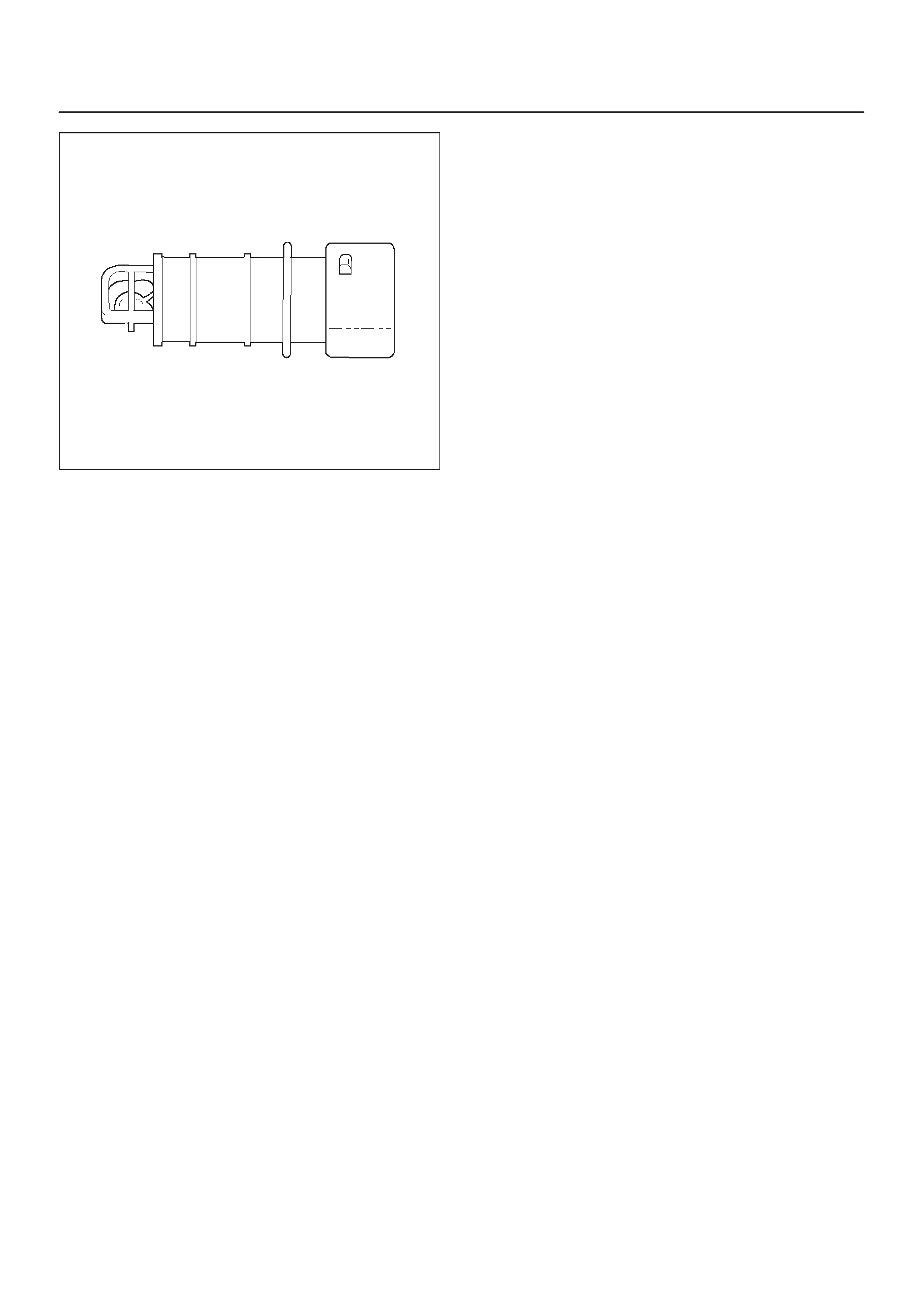
0018
Manifold Absolute Pressure (MAP) Sensor
The manifold absolute pressure (MAP) sensor responds
to changes in intake manifold pressure. The MAP sensor
signal voltage to the ECM varies from below 2 volts at idle
(high vacuum) to above 4 volts.
The MAP sensor is used to determine the following:
DBoost pressure for injector control.
DBarometric pressure (BARO).
If the ECM detects a voltage that is lower than the
possible range of the MAP sensor, DTC P0107 will be set.
A signal voltage higher than the possible range of the
sensor will set DTC P0108. An intermittent low or high
voltage will set DTC P1107 or DTC P1106, respectively.
The ECM can detect a shifted MAP sensor. The ECM
compares the MAP sensor signal to a calculated MAP
based on throttle position and various engine load factors.
If the ECM detects a MAP signal that varies excessively
above or below the calculated value, DTC P0106 will set.
Engine Control Module (ECM)
The engine control module (ECM) is located in the engine
room.
The ECM constantly observes the information from
various sensors. The ECM controls the systems that
affect vehicle performance. The ECM performs the
diagnostic function of the system. It can recognize
operational problems, alert the driver through the MIL
(Service Engine Soon lamp), and store diagnostic trouble
codes (DTCs). DTCs identify the problem areas to aid the
technician in making repairs.
ECM Function
The ECM supplies 5, 12 and 110 volts to power various
sensors or switches. The power is supplied through
resistances in the ECM which are so high in value that a
test light will not light when connected to the circuit. In
some cases, even an ordinary shop voltmeter will not give
an accurate reading because its resistance is too low.
Therefore, a digital voltmeter with at least 10 megohms
input impedance is required to ensure accurate voltage
readings. The ECM controls output circuits such as the
injectors, glow relays, etc., by controlling the ground or
the power feed circuit through transistors or through
either of the following two devices:
DOutput Driver Module (ODM)
DQuad Driver Module (QDM)
ECM Components
The ECM is designed to maintain exhaust emission levels
to government mandated standards while providing
excellent driveability and fuel efficiency. The ECM
monitors numerous engine and vehicle functions via
electronic sensors such as the crankshaft position (CKP)
sensor, and vehicle speed sensor (VSS). The ECM also
controls certain engine operations through the following:
DFuel injector control
DRail pressure control
ECM Voltage Description
The ECM supplies a buffered voltage to various switches
and sensors. It can do this because resistance in the
ECM is so high in value that a test light may not illuminate
when connected to the circuit. An ordinary shop
voltmeter may not give an accurate reading because the
voltmeter input impedance is too low . Use a 10-megohm
input impedance digital voltmeter to assure accurate
voltage readings.
The input/output devices in the ECM include
analog-to-digital converters, signal buffers, counters,
and special drivers. The ECM controls most components
with electronic switches which complete a ground circuit
when turned “ON.” These switches are arranged in
groups of 4 and 7, called either a surface-mounted quad
driver module (QDM), which can independently control up
to 4 output terminals, or QDMs which can independently
control up to 7 outputs. Not all outputs are always used.
ECM Input/Outputs
Inputs – Operating Conditions Read
DAir Conditioning “ON” or “OFF”
DEngine Coolant Temperature
DCrankshaft Position
DElectronic Ignition
DManifold Absolute Pressure
DBattery Voltage
DIntake Throttle Position
DVehicle Speed
DFuel Temperature
DOil Temperature
DIntake Air Temperature
DEGR boost pressure
DOil rail pressure
DCamshaft Position
DAccelerator position
Outputs – Systems Controlled
DExhaust Gas Recirculation (EGR)
DInjector Control
DQWS

DQOS
DDiagnostics
–Malfunction Indicator Lamp (Service Engine
Soon lamp)
–Data Link Connector (DLC)
–Data Output
ECM Service Precautions
The ECM is designed to withstand normal current draws
associated with vehicle operation. Avoid overloading any
circuit. When testing for opens and shorts, do not ground
or apply voltage to any of the ECM’s circuits unless
instructed to do so. These circuits should only be tested
using digital voltmeter. The ECM should remain
connected to the ECM or to a recommended breakout
box.
Intake Throttle Position (ITP) Sensor
ITP sensor is a potentiometer type and installed to the
intake throttle valve body. A voltage of 5V is applied
constantly from ECM to ITP sensor thereby to determine
by change in voltage the opening of the intake throttle
valve during warming up.
Transmission Range Switch
IMPORTANT:The vehicle should not be driven with the
transmission range switch disconnected; idle quality will
be affected.
The four inputs from the transmission range switch
indicate to the ECM which position is selected by the
transmission selector lever.
For more information on the transmission on the
transmission range switch, refer to
Automatic
Transmission
.
Accelerator Position Sensor (AP)
AP sensor is a potentiometer type and installed to
accelerator pedal bracket. A voltage of 5V constantly
applied from ECM to the sensor thereby to determine the
accelerator pedaling angle by change in voltage. Further ,
this sensor is provided with an accelerator switch, which
is set off only when the accelerator pedal is stepped on.
Aftermarket Electrical and Vacuum
Equipment
Aftermarket (add-on) electrical and vacuum equipment is
defined as any equipment which connects to the vehicle’s
electrical or vacuum systems that is installed on a vehicle
after it leaves the factory. No allowances have been
made in the vehicle design for this type of equipment.
NOTE: No add-on vacuum equipment should be added
to this vehicle.
NOTE: Add-on electrical equipment must only be
connected to the vehicle’s electrical system at the battery
(power and ground).
Add-on electrical equipment, even when installed to
these guidelines, may still cause the powertrain system to
malfunction. This may also include equipment not
connected to the vehicle electrical system such as
portable telephones and radios. Therefore, the first step
in diagnosing any powertrain problem is to eliminate all
aftermarket electrical equipment from the vehicle. After
this is done, if the problem still exists, it may be diagnosed
in the normal manner.
Electrostatic Discharge Damage
Electronic components used in the ECM are often
designed to carry very low voltage. Electronic
components are susceptible to damage caused by
electrostatic discharge. Less than 100 volts of static
electricity can cause damage to some electronic
components. By comparison, it takes as much as 4000
volts for a person to feel even the zap of a static
discharge.
TS23793
There are several ways for a person to become statically
charged. The most common methods of charging are by
friction and induction.
DAn example of charging by friction is a person sliding
across a vehicle seat.
DCharge by induction occurs when a person with well
insulated shoes stands near a highly charged object
and momentary touches ground. Charges of the
same polarity are drained off leaving the person
highly charged with the opposite polarity. Static
charges can cause damage, therefore it is important
to use care when handling and testing electronic
components.
NOTE: To prevent possible electrostatic discharge
damage, follow these guidelines:
DDo not touch the ECM connector pins or soldered
components on the ECM circuit board.
DDo not open the replacement part package until the
part is ready to be installed.
DBefore removing the part from the package, ground
the package to a known good ground on the vehicle.
DIf the part has been handled while sliding across the
seat, while sitting down from a standing position, or
while walking a distance, touch a known good ground
before installing the part.

General Description (Air Induction)
Air Induction System
The air induction system filters contaminants from the
outside air, and directs the progress of the air as it is
drawn into the engine. A remote-mounted air cleaner
prevents dirt and debris in the air from entering the
engine. The air duct assembly routes filtered air to the
throttle body. Air enters the engine by to following steps:
1.Through the throttle body.
2.Into the intake manifold.
3.Through the cylinder head intake ports.
4.Into the cylinders.
General Description (Fuel Metering)
Deceleration Mode
The ECM reduces the amount of fuel injected when it
detects a decrease in the Accelerator position.
Fuel Injector
Fuel injector comprises the solenoid, hydraulic line, and
fuel line. Fuel injection is controlled by the continuity time
signal and continuity start timing signal from ECM to the
solenoid
ECM determines the running conditions of engine by
input signals such as engine speed. Accelerator throttle
valve opening, and engine coolant temperature, thereby
to send the solenoid the best suited signal to the engine
status. When current is carried to the solenoid, the
armature opens the poppet valve to alow high pressure oil
to run into the injector. Under the pressure of the oil, the
piston and plunger are depressed to compress the fuel in
the combustion chamber of the plunger. Specifically, the
pressure of the fuel compressed is increased by a piston
top/ plunger bottom area ratio over the pressure of high
pressure oil, thereby lifting the fuel nozzle end needle for
injecting fuel.
Fuel Metering System Components
The fuel metering system is made up of the following
parts:
DThe fuel injectors.
DThe intake throttle body.
DThe Accelerator position (AP) sensor
DThe ECM.
DThe crankshaft position (CKP) sensor.
DThe camshaft position (CMP) sensor.
Basic System Operation
Fuel is supplied through fuel filter to the fuel pump.
The fuel pump is installed to the oil pump, and fuel is
forced, through the fuel pump outlet, pipe and cylinder
head inside, into the fuel injector.
An orifice is provided at the rear fuel outlet of cylinder
head to control the pressure of oil.
The injector is controlled by ECM which gives
opening/closing commands to the solenoid installed on
the top of the injector. Opening/closing operation of the
pressurized engine oil circuit of the injector controls fuel
injection quantity, fuel injection timing, etc.
A/C Clutch Diagnosis
A/C Request Signal
This signal tells the ECM when the A/C mode is selected
at the A/C control head. The ECM uses this to adjust the
idle speed.
General Description Exhaust Gas
Recirculation (EGR) System
EGR Purpose
The exhaust gas recirculation (EGR) system is use to
reduce emission levels of oxides of nitrogen (NOx). NOx
emission levels are caused by a high combustion
temperature. The EGR system lowers the NOx emission
levels by decreasing the combustion temperature.
The ECM uses information from the following sensors to
control EGR valve boost pressure.
DECT
DITP
DEngine Speed
DAP sensor
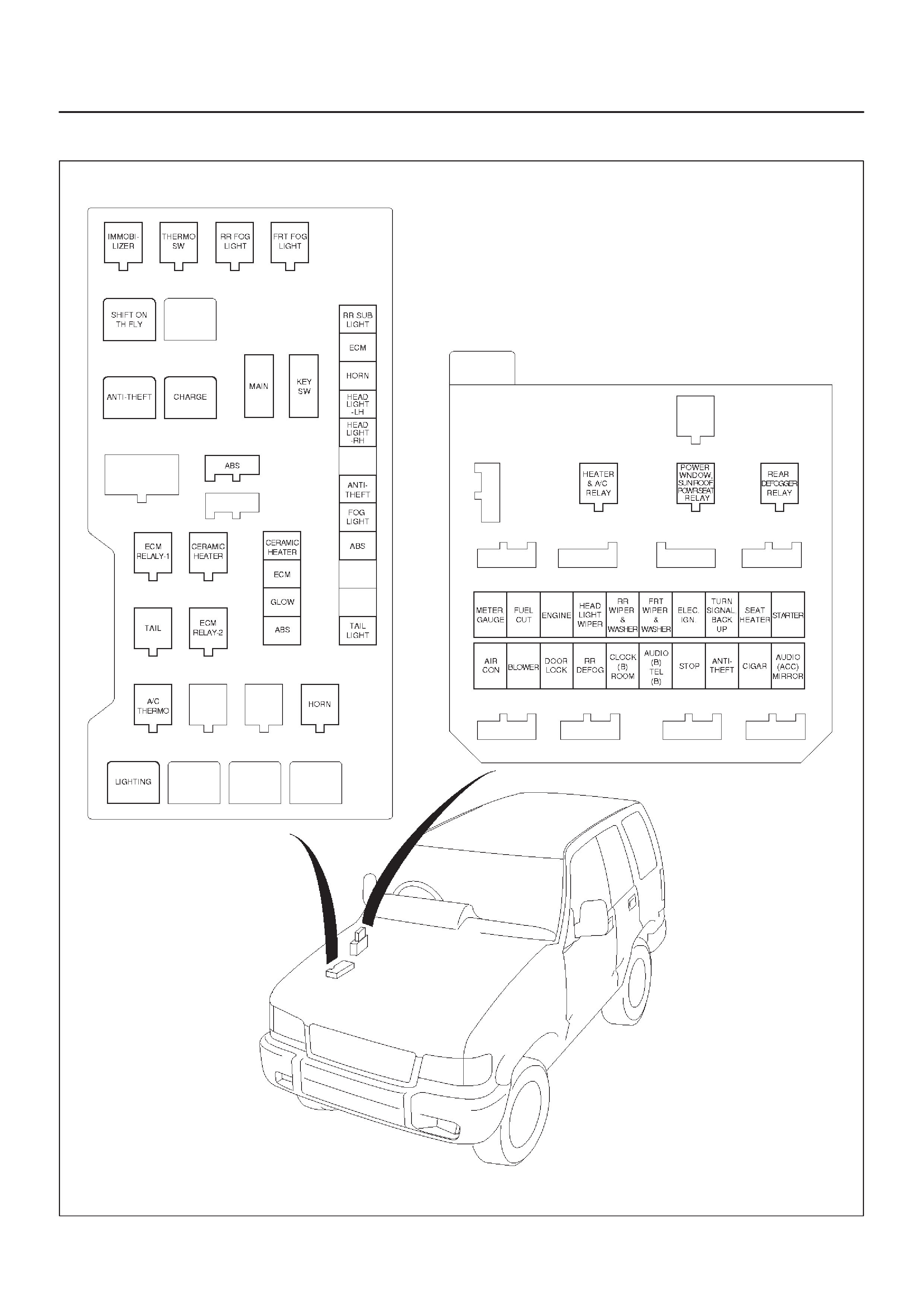
Fuse and Relay Panel (Underhood Electrical Center)
035RW109