GENERALDESCRIPTION
LUBRICATION CHART
33
32
31
30
1
2
34
5
6
8
9
7
10
11 12
13 14
23
29
25
28 27 26
24
15 16
1718
19202122
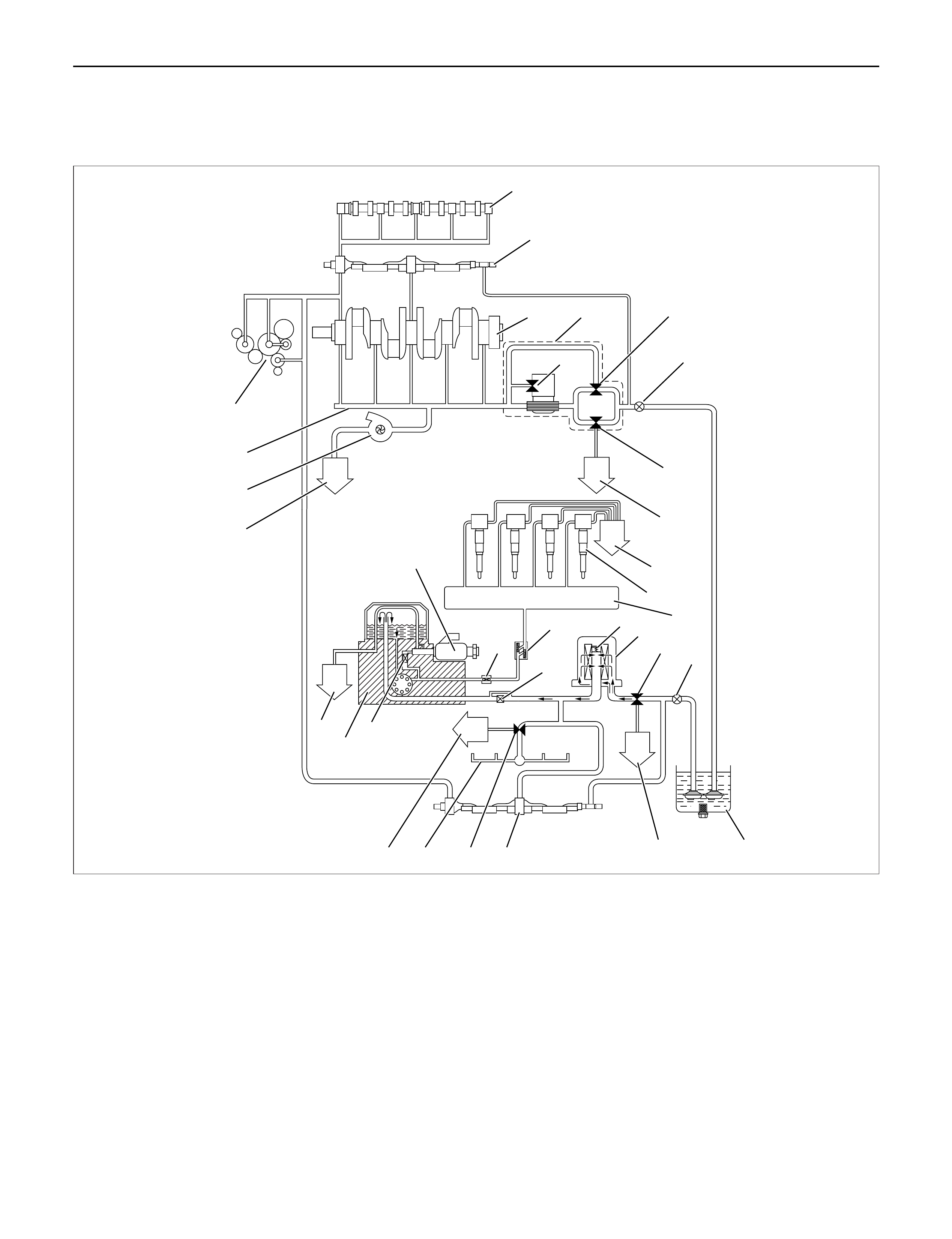
Legend
(1) Camshaft
(2) Balance Shaft
(3) Crankshaft
(4) Oil Cooler and Oil Filter Assembly
(5) Oil Filter Relief Valve 98 Kpa (1 kg/cm2/14.2 Psi)
(6) Oil Cooler Relief Valve 245 Kpa (2.5 kg/cm2/
36 Psi)
(7) First Oil Pump
(8) Main Oil Relief Valve 588 Kpa (6 kg/cm2/ 85 Psi)
(9) To Oil Pan
(10) To Oil Pan
(11) Injector
(12) Oil Rail
(13) Sub Oil Filter Relief Valve 98 Kpa (1 kg/cm2/
14.2 Psi)
(14) Sub Oil Filter
(15) Relief Valve 588 Kpa (6 kg/cm2/ 85 Psi)
(16) Second Oil Pump
(17) Oil Pan
(18) To Oil Pan
(19) Balance Shaft
(20) Cooling Jet Relief Valve 245 Kpa (2.5 kg/cm2/
36 Psi)
(21) Cooling Jet
(22) To Oil Pan
(23) Two Way Check Valve
(24) Nipple Filter
040RW018
To meet the requirements of the 4JX1-TC HUEI
fuel injection system, two engine oil pumps have
been provided to ensure adequate oil flow.
The first oil pump serves mainly to lubricate the engine
parts, while the second mainly serves the fuel injectors
and partially cools the pistons.
The oil cooler is provided on the first oil pump side and
uses engine coolant.
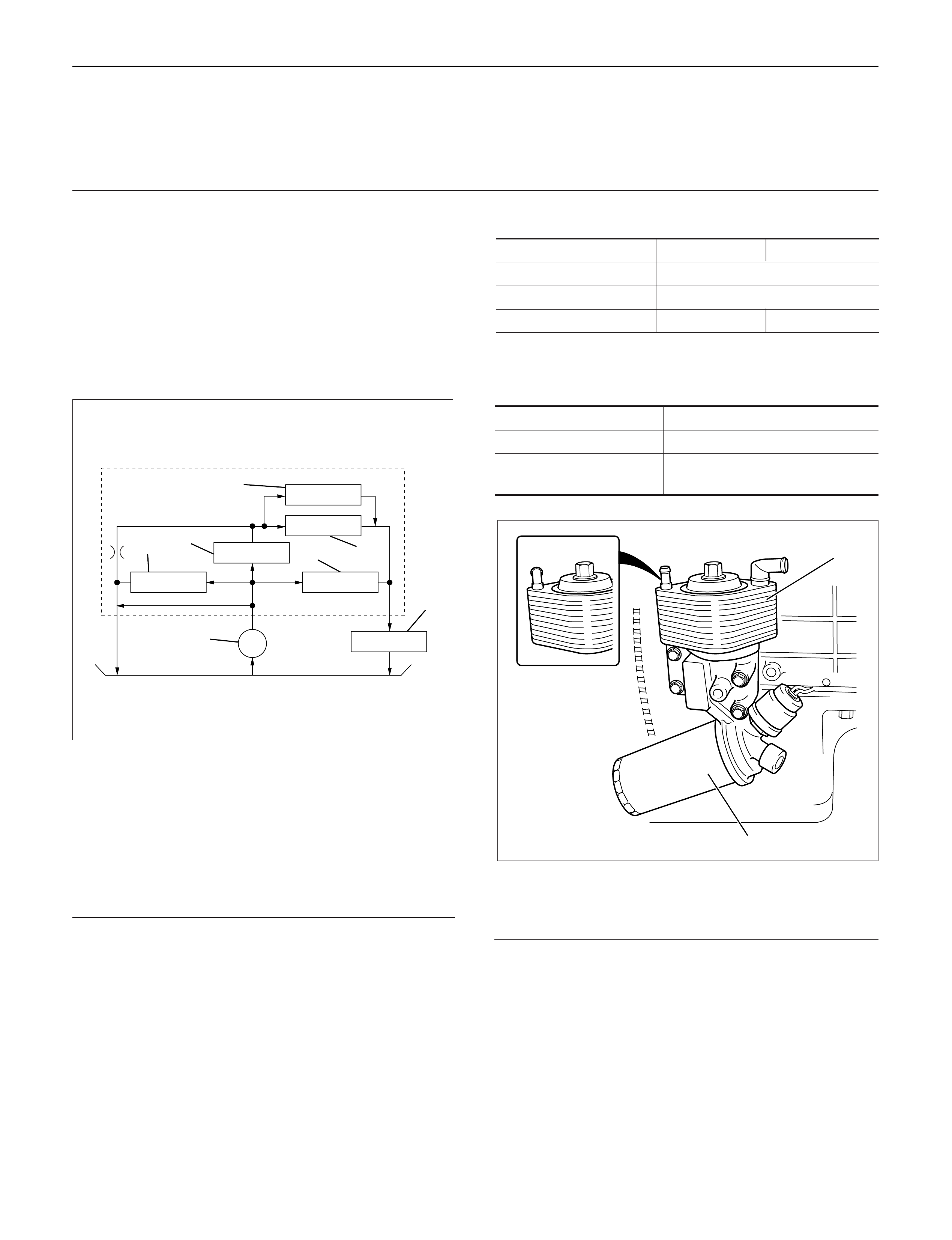
OILFLOW
Legend
(1) Oil Pump
(2) Regulator Valve
(3) Oil Cooler
(4) Oil Filter Relief Valve
(5) Full Flow Filter
(6) Oil Cooler Relief Valve
(7) Gallery
OILPUMPSPECIFICATIONS
First Second
Pump Revolution 8800 rpm
Delivery Pressure 392 Kpa (4.0 kg/cm2/57 psi)
Delivery Capacity >48.8 l/min >37.1 l/min
OILFILTER SPECIFICATIONS
Filtration MethodFull flow Paper
Filtration Area 0.32 m2
Relief Valve opening
981 Kpa (10 kg/cm2/142 psi)
pressure
Legend
(1) Oil cooler assembly
(2) Oil filter assembly
(25) Edge Filter
(26) Edge Filter
(27) High Pressure Oil Pump Assembly
(28) To Oil Pan
(29) Pressure Control Valve
(30) To Oil Pan
(31) Turbocharger
(32) Oil Gallery
(33) Timing Gear Train
1
7
65
4
3
2
050RW010
MY2003 Euro-3 1
2
050R200001
SUB OILFILTER SPECIFICATIONS
Filtration Method Full flow Paper
Filtration Area 0.12 m2
Relief Valve opening
981 Kpa (10 kg/cm2/142 psi)
pressure
The sub oil filter requires replacement after every
20,000km of engine operation.
It is recommended to check and replace the sub filter
whenever the engine is being overhauled.
442RW004
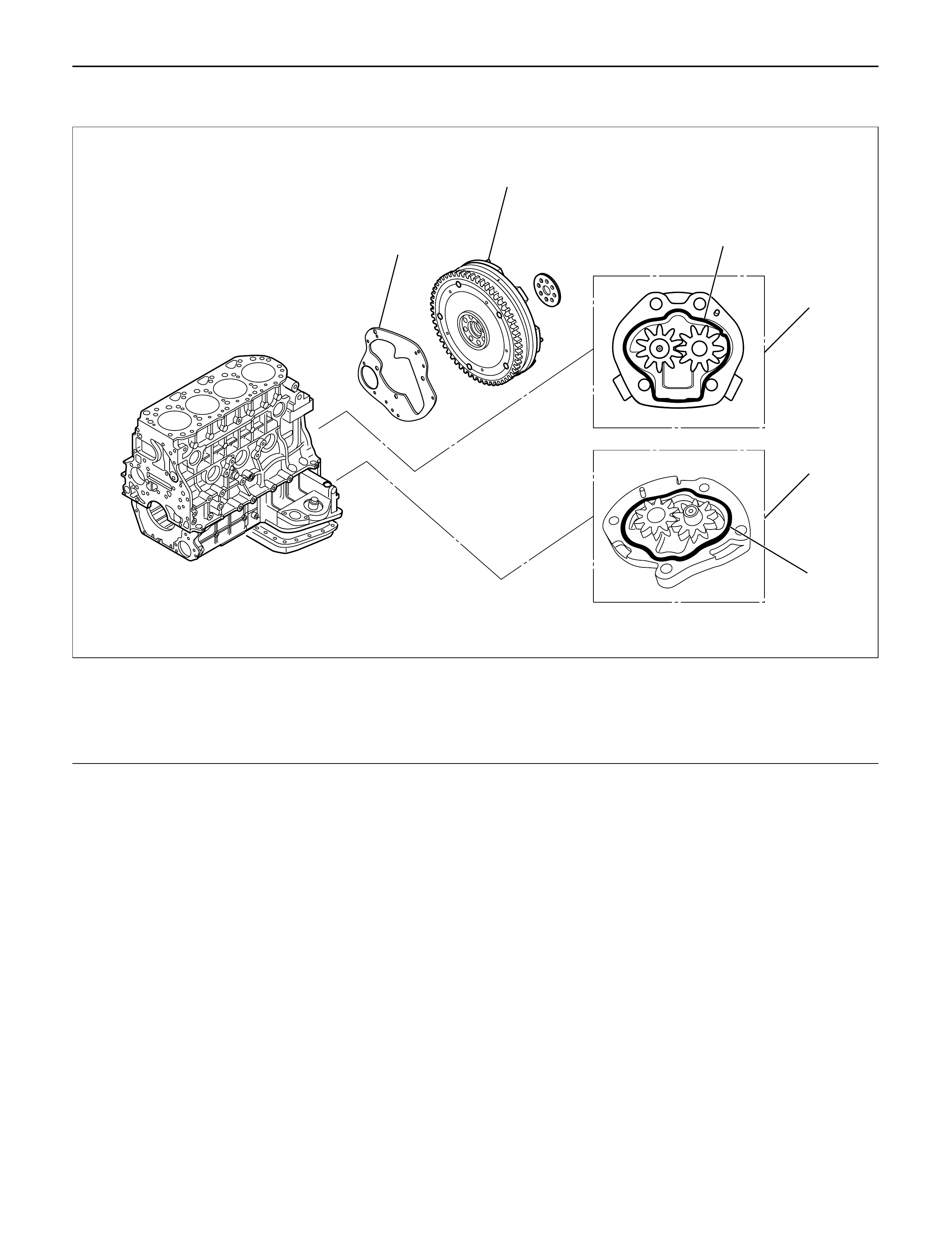
OILPUMP
REMOVAL
1. Remove battery ground cable.
2 Raise the vehicle and support with suitable safety
stand.
3. Drain engine oil.
4. Remove flywheel assembly.
5. Remove rear plate (For A/T) or flywheel housing
(For MT).
6. Remove first oil pump assembly from cylinder block
and second oil pump assembly from crank case.
INSPECTION AND REPAIR
1. Inspect flaws and/or wear on the teeth surface.
2. Inspect abnormal wear journal on the gear and in
the drive spline.
3. If problem is found during inspection, the worn parts
must be replaced.
INSTALLATION
1. Install first oil pump.
1) Set O-ring to oil pump.
2) Install oil pump drive gear to the end of
balance shaft RH.
3) Apply engine oil to oil pump gear and install
gear to the end surface of cylinder block.
Torque: 20 N·m (2.0 kg·m / 14 lb ft)
2. Install second oil pump.
1) Set O-ring to oil pump.
2) Install oil pump drive gear to the end of
balance shaft LH.
3) Apply engine oil to oil pump gear and install
gear to the end surface of crankcase.
Torque: 20 N·m (2·0 kg.m / 14 lb ft)
2
1
5
6
3
4
Legend
(1) Flywheel
(2) Rear Plate
(3) First Oil Pump
(4) Second Oil Pump
(5) O-ring (For 1st oil pump)
(6) O-ring (For 2nd oil pump)
012RW097
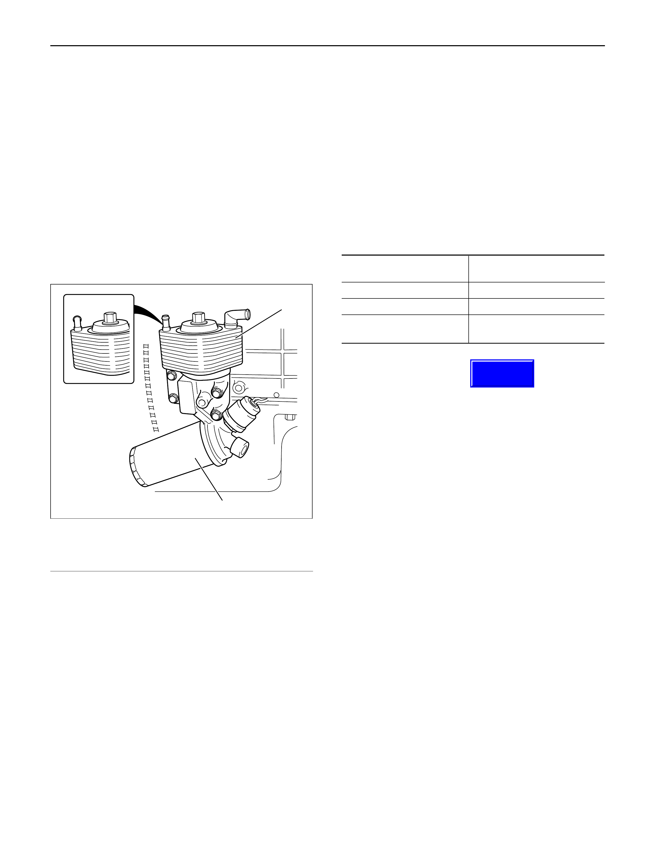
OILCOOLER ASSEMBLY
REMOVAL
1. Disconnect battery ground cable.
2. Drain engine coolant.
3. Remove front exhaust pipe.
4. Remove heat protector.
5. Remove exhaust valve assembly.
6. Oil cooler assembly.
1) Remove water hose from water inlet and outlet
side.
2) Cloth should be put under the oil cooler to
prevent oil from flowing out.
3) Loosen fixing bolt then remove oil cooler
assembly.
Legend
(1) Oil cooler assembly
(2) Oil filter assembly
INSPECTION AND REPAIR
1. Inspect for corrosion, wear, and breaks on the oil
cooler core.
2. If a problem is found on the oil cooler core, the oil
cooler assembly must be replaced.
INSTALLATION
1. Oil cooler assembly
1) Tighten oil cooler fixing bolt to the specified
torque and install water hoses.
Torque: 29 N·m (3.0 kg·m / 22 lb ft)
2. Install exhaust valve assembly to turbocharger
assembly and tighten to the specified torque.
Torque: 27 N·m (2.8 kg·m / 20 lb ft)
3. Install front exhaust pipe to the exhaust valve.
Torque:
67 N·m (6.8 kg·.m / 49 lb ft)
(At exhaust valve side)
43 N·m (4.4 kg·m / 32 lb ft)
(At center exhaust pipe side)
4. Install heater protector.
5. Fill engine coolant.
6. Connect battery ground cable.
7. Start engine and carefully check for leakage of oil
and coolant.
OILCOOLER SPECIFICATIONS
Cooling method Water cooled
Multi plate type
Heat exchange Area 0.323 m2
Heat exchange capacity >11,300 kcl/h
Relief Valve opening
245 Kpa (2.5 kg/cm2/36 psi)
pressure
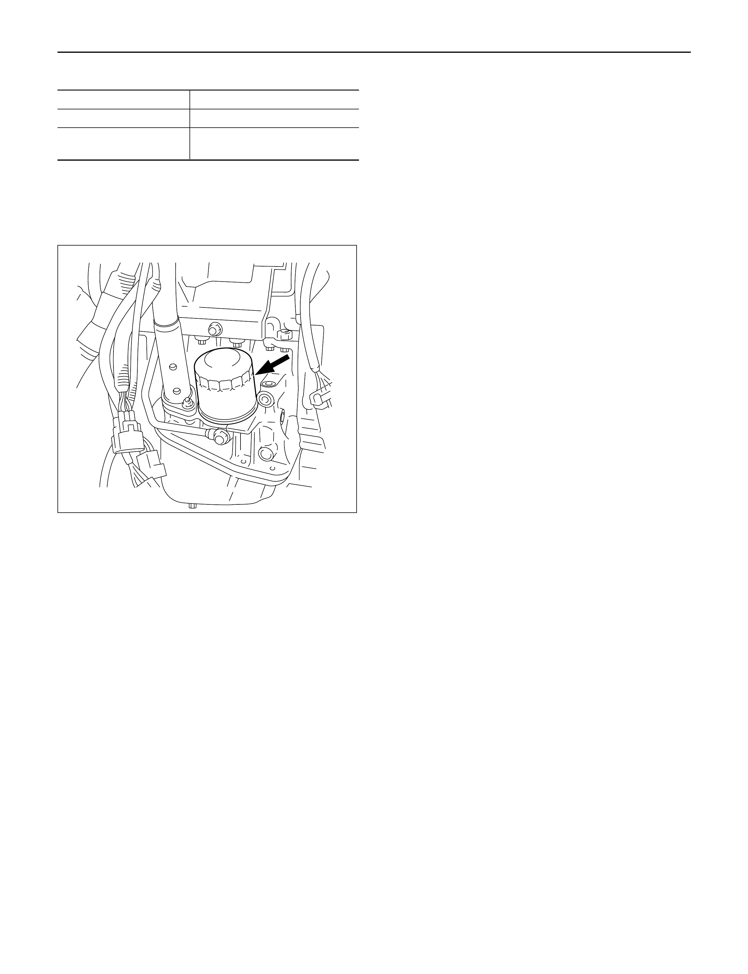
OILFILTER
REMOVAL
1. Put container under the oil filter to prevent oil from
the oil filter from flowing out.
2. Use filter wrench to remove oil filter.
Filter wrench: 5-8840-0203-0
INSTALLATION
1. Apply engine oil thinly to oil filter O-ring.
2. Tighten oil filter by hand until O-ring comes in
contact with the sealing surface.
3. Use filter wrench to tighten oil filter one turn and 1/8
turn.
4. Start engine and carefully check for oil leakage from
oil filter.
SUB OILFILTER
The sub oil filter requires replacement after every
20,000km of engine operation.
It is recommended to check and replace the sub oil filter
when the engine is being overhauled.
MY2003 Euro-3 1
2
050R200001
Techline