
GENERAL DESCRIPTION
2
1
101R200006
The conventional throttle cable type engine speed
control system has been replaced with an electronic
system utilising an Accelerator Position (AP) sensor.
The AP sensor is a potentiometer (variable resistor)
installed on the accelerator pedal bracket.
A 5V reference is applied from the Engine Control
Module (ECM) to the AP sensor, the operating angle of
the accelerator pedal being detected by the ECM
monitoring the returned voltage signal.
The AP sensor is also fitted with an Idle Position Switch.
The switch is closed when the accelerator pedal is in
the idle position, and open at 'Off-idle'.
A return cable and spring having the same sliding
resistance of a conventional cable, help to give a more
normal 'feel' to the accelerator pedal.
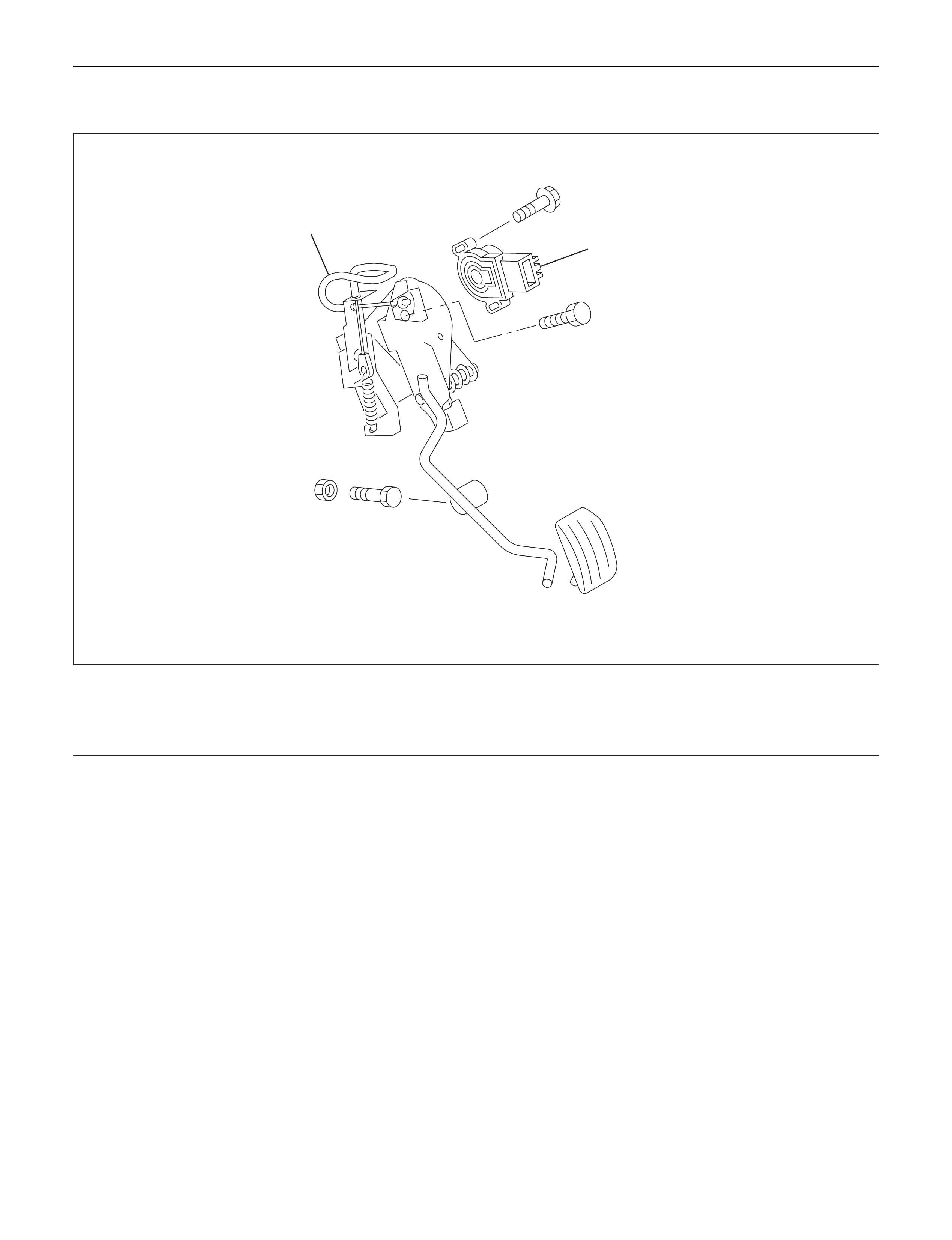
Legend
(1) Accelerator Position (AP) Sensor
(2) Return Cable

REMOVAL
1. Remove the harness connector from the AP
sensor.
2. Remove accelerator pedal assembly from the body.
INSPECTION AND REPAIR
1. Check the mechanical operation of accelerator pedal,
apply oil to the pivot etc. if required.
2. Check the mounting of the AP sensor to the pedal
bracket, tighten if necessary.
INSTALLA TION
1. Install accelerator pedal assembly to the body.
2. Connect the harness connector to the AP sensor.
ACCELERATOR PEDAL