
SECTION 6A1 - ENGINE MECHANICAL
Service Precaution
General Description
Engine Diagnosis
Cylinder Head Cover LH
Removal
Installation
Cylinder Head Cover RH
Removal
Installation
Common Chamber
Removal
Installation
Exhaust Manifold LH
Removal
Installation
Exhaust Manifold RH
Removal
Installation
Crankshaft Pulley
Removal
Installation
Timing Belt - Broken Belt
Removal
Installation
Timing Belt Replacement - Service Operation
Removal
Installation
Installation
Camshaft
Removal
Installation
Cylinder Head
Removal
Installation
Valve Stem Oil Controller , Valve Spring and Valve
Guide
Removal
Installation
Piston, Piston Ring and Connecting Rod
Removal
Installation
Crankshaft and Main Bearings
Removal
Installation
Rear Oil Seal
Removal
Installation
Engine Assembly
Removal
Installation
Cylinder Head
Cylinder Head and Associated Parts
Disassembly
Clean
Inspection and Repair
Reassembly
Valve Spring, Oil Controller, Valve, Valve Guide
Valve Spring, Oil Controller, Valve, Valve Guide and
Associated Parts
Disassembly
Inspection and Repair
Reassembly
Valve Clearance Adjustments
Camshaft
Camshaft and Associated Parts
Disassembly
Inspection and Repair
Reassembly
Crankshaft
Crankshaft and Associated Parts
Disassembly
Inspection and Repair
Inspection and Repair
Reassembly
Piston and Connecting Rod
Piston, Connecting Rod and Associate Parts
Disassembly
Inspection and Repair
Reassembly
Cylinder Block
Cylinder Block and Associated Parts
Disassembly
Inspection and Repair
Reassembly
Main Data and Specification
Special Tool
Techline

Service Precaution
WARNING: IF SO EQUIPPED WITH A
SUPPLEMENTAL RESTRAINT SYSTEM (SRS),
REFER TO THE SRS COMPONENT AND WIRING
LOCATION VIEW IN ORDER TO DETERMINE
WHETHER YOU ARE PERFORMING SERVICE ON
OR NEAR THE SRS COMPONENTS OR THE SRS
WIRING. WHEN YOU ARE PERFORMING SERVICE
ON OR NEAR THE SRS COMPONENTS OR THE
SRS WIRING, REFER TO THE SRS SERVICE
INFORMATION. FAILURE TO FOLLOW WARNINGS
COULD RESULT IN POSSIBLE AIR BAG
DEPLOYMENT, PERSONAL INJURY, OR
OTHERWISE UNNEEDED SRS SYSTEM REPAIRS.
CAUTION: Always use the correct fastener in the
proper location. When you replace a fastener, use
ONLY the exact part number for that application.
HOLDEN will call out those fasteners that require a
replacement after removal. HOLDEN will also call
out the fasteners that require thread lockers or
thread sealant. UNLESS OTHERWISE SPECIFIED,
do not use supplemental coatings (Paints, greases,
or other corrosion inhibitors) on threaded fasteners
or fastener joint interfaces. Generally, such
coatings adversely affect the fastener torque and
the joint clamping force, and may damage the
fastener. When you install fasteners, use the
correct tightening sequence and specifications.
Following these instructions can help you avoid
damage to parts and systems.

General Description
Engine Cleanliness And Care
An automobile engine is a combination of many
machined, honed, polished and lapped surfaces with
tolerances that are measured in the thousandths of a
millimeter (ten thousandths of an inch). Accordingly,
when any internal engine parts are serviced, care and
cleanliness are important. Throughout this section, it
should be understood that proper cleaning and
protection of machined surfaces and friction areas is
part of the repair procedure. This is considered standard
shop practice even if not specifically stated.
• A liberal coating of engine oil should be applied to all
friction areas during assembly to protect and lubricate
the surfaces on initial operation.
• Whenever valve train components, pistons, piston
rings, connecting rods, rod bearings, and crankshaft
journal bearings are removed for service, they should
be retained in order.
• At the time of installation, they should be installed in
the same locations and with the same mating
surfaces as when removed.
• Battery cables should be disconnected before any
major work is performed on the engine. Failure to
disconnect cables may result in damage to wire
harness or other electrical parts.
• The six cylinders of this engine are identified by
numbers; Right side cylinders 1, 3 and 5, Left side
cylinders 2, 4 and 6, as counted from crankshaft
pulley side to flywheel side.
General Information on Engine Service
The following information on engine service should be
noted carefully, as it is important in preventing damage
and contributing to reliable engine performance:
• When raising or supporting the engine for any
reason, do not use a jack under the oil pan. Due to
the small clearance between the oil pan and the oil
pump strainer, jacking against the oil pan may cause
damage to the oil pick–up unit.
• The 12–volt electrical system is capable of damaging
circuits. When performing any work where electrical
terminals could possibly be grounded, the ground
cable of the battery should be disconnected at the
battery.
• Any time the intake air duct or air cleaner is removed,
the intake opening should be covered. This will
protect against accidental entrance of foreign
material into the cylinder which could cause
extensive damage when the engine is started.
Cylinder Block
The cylinder block is made of aluminum die–cast
casting for 75°V–type six cylinders. It has a rear plate
integrated structure and employs a deep skint. The
cylinder liner is cast and the liner inner diameter and
crankshaft journal diameter are classified into grades.
The crankshaft is supported by four bearings of which
width of No.3 bearing on the body side is different in
order to support the thrust bearing. The bearing cap is
made of nodular cast iron and each bearing cap uses
four bolts and two side bolts.
Cylinder Head
The cylinder head, made of aluminum alloy casting
employs a pent–roof type combustion chamber with a
spark plug in the center. The intake and exhaust valves
are placed in V–type design. The ports are cross–flow
type.
Valve Train
Intake and exhaust camshaft on the both side of banks
are driven through an camshaft drive gear by timing
belt. The valves are operated by the camshaft and the
valve clearance is adjusted to select suitable thickness
shim.
Intake Manifold
The intake manifold system is composed of the
aluminum cast common chamber and intake manifold
attached with six fuel injectors.
Exhaust Manifold
The exhaust manifold is made of nodular cast iron.
Pistons and Connecting Rods
Aluminum pistons are used after selecting the grade
that meets the cylinder bore diameter. Each piston has
two compression rings and one oil ring. The piston pin is
made of chromium steel is offset 1mm toward the thrust
side, and the thrust pressure of piston to the cylinder
wall varies gradually as the piston travels. The
connecting rods are made of forged steel. The
connecting rod bearings are graded for correct seze
selection.
Crankshaft and Bearings
The crankshaft is made of Ductile cast–iron. Pins and
journals are graded for correct size selection for their
bearing.
Engine Lubrication
The oil discharged by a trochoid–type oil pump driven
by the crankshaft is fed through full–flow oil filter and to
the oil gallery provided under the crankshaft bearing
cap. The oil is then led to the crankshaft journals and
cylinder head. The crank pins are lubricated with oil
from crankshaft journals through oil holes. Also, an oil
jet is fed to each cylinder from crankshaft juornals on
the connecting rod for piston cleaning. The oil pan
flange is dealed with liquid packing only; do not deform
or damage the flange surface during removal or
installation.
Engine Diagnosis
Hard Starting
1. Starting Motor Does Not Turn Over
Troubleshooting Procedure
Turn on headlights and starter switch.
2. Ignition Trouble — Starter Motor Turns Over But Engine Does Not Start
Spark Test
Disconnect an igniton coil from any spark plug. Connect
the spark plug tester 5–8840–0607–0, start the engine,
and check if a spark is generated in the spark plug
tester. Before starting the engine, make sure that the
spark plug tester is properly grounded. To avoid
electrical shock, do not touch the part where insulation
of the igniton coil is broken while the engine is running.
3. Fuel System Fault
Condition Possible Cause Corrction
Headlights go out or dim
considerably
Battery run down or under charged Recharge or replace battery
Terminals poorly connected Clean battery posts and terminals
and connect properly
Starting motor coil circuit shorted Overhaul or replace
Starting motor defective Overhaul or replace
Condition Possible Cause Correction
Spark jumps across gap Spark plug defective Clean, adjust spark gap or replace
Ignition timing incorrect Refer to Ignition System
Fuel not reaching fuel injector(s) or
engine
Refer to item 3 (Trouble in fuel
system)
Valve timing incorrect Adjust
Engine lacks compression Refer to item 4 (Engine lacks
compression)
No sparking takes place Ignition coil disconnected or broken Connect properly or replace
Electronic Ignition System with
module
Replace
Poor connections in engine harness Correct
Powertrain Control Module cable
disconnected or defective
Correct or replace
Condition Possible Cause Correction
Starter motor turns over and spark
occurs but engine does not start.
Fuel tank empty Fill
Water in fuel system Clean
Fuel filter clogged Replace filter
Fuel pipe clogged Clean or replace
Fuel pump defective Replace
Fuel pump circuit open Correct or replace
Evaporative Emission Control
System circuit clogged
Correct or replace
Multiport Fuel Injection System faulty Refer to “Electronic Fuel Injection”
section
4. Engine Lacks Compression
Engine Compression Test Procedure
1. Start and run the engine until the engine reaches
normal operating temperature.
2. Turn the engine off.
3. Remove all the spark plugs.
4. Remove ignition coil fuse (15A) and disable the
ignition system.
5. Remove the fuel pump relay from the relay and fuse
box.
6. Engage the starter and check that the cranking
speed is approximately 300 rpm.
7. Install cylinder compression gauge into spark plug
hole.
8. With the throttle valve opened fully, keep the starter
engaged until the compression gage needle
reaches the maximum level. Note the reading.
9. Repeat the test with each cylinder.
If the compression pressure obtained falls below the
limit, engine overhaul is necessary.
Limit; 1000 kPa (145 psi)
Condition Possible Cause Correction
Engine lacks compression Spark plug loosely fitted or spark plug
gasket defective
Tighten to specified torque or replace
gasket
Valve timing incorrect Adjust
Cylinder head gasket defective Replace gasket
Valve incorrectly seated Lap valve
Valve stem seized Replace valve and valve guide
Valve spring weakened or broken Replace
Cylinder or piston rings worn Overhaul engine
Piston ring seized Overhaul engine.
Rough Engine Idling or Engine Stalling
Condition Possible Cause Correction
Fuel injection system failure Idle air control valve defective Replace
Throttle shutting off incomplete Correct or replace
Throttle position sensor circuit open
or shorted
Correct or replace
Fuel injector circuits open or shorted Correct or replace
Fuel injectors damaged Replace
Fuel pump relay defective Replace
Mass Airflow Sensor circuit open or
poor connections
Correct or replace
Mass Airflow Sensor defective Replace
Manifold Absolute Pressure Sensor
circuit open or poor connections
Correct or replace
Manifold Absolute Pressure Sensor
defective
Replace
Engine Coolant Temperature Sensor
circuit open or poor connections
Correct or replace
Engine Coolant Temperature Sensor
defective
Replace
Intake Air Temperature sensor circuit
open or poor connections
Correct or replace
Intake Air Temperature sensor
defective
Replace
Knock Sensor (KS) cable broken or
poor connections
Correct or replace
KS defective Replace
KS Module circuits open or ground Correct or replace
KS Module defective Replace
Vehicle Speed Sensor circuit open or
shorted
Correct or replace
Vehicle Speed Sensor defective Replace
Emission control system failure Powertrain Control Module defective Replace
Exhaust Gas Recirculation Valve
circuit open or poor connections
Correct or replace
Exhaust Gas Recirculation Valve
faulty
Replace
Canister purge valve circuit open or
poor connections
Correct or replace
Canister purge valve defective Replace
Evaporative Emission Canister Purge
control valve defective
Replace
Trouble in ignition system Refer to “Hard Start”
Rough Engine Running
Others Engine lacks compression Refer to “Hard Start”
Valve incorrectly seated Lap valve
Air Cleaner Filter clogged Replace filter element
Valve timing incorrect Readjust
Idle air control valve broken Replace
Fast idle solenoid defective Replace
Positive Crankcase Ventilation valve
defective or clogged
Replace
Condition Possible Cause Correction
Condition Possible Cause Correction
Engine misfires periodically Ignition coil layer shorted Replace
Spark plugs fouling Clean or install hotter type plug
Spark plug(s) insulator nose leaking Replace
Fuel injector(s) defective Replace
Powertrain control module faulty Replace
Engine knocks periodically Spark plugs running too hot Install colder type spark plugs
Powertrain control module faulty Replace
Engine lacks power Spark plugs fouled Clean
Fuel injectors defective Replace
Mass Airflow Sensor or Intake Airflow
Sensor circuit defective
Correct or replace
Manifold Absolute Pressure (MAP)
Sensor or Manifold Absolute
Pressure Sensor circuit defective
Correct or replace
Engine Coolant Temperature Sensor
or Engine Coolant Temperature
Sensor circuit defective
Correct or replace
Powertrain Control Module faulty Replace
Intake Air Temperature Sensor or
Intake Air Temperature Sensor circuit
defective
Correct or replace
Throttle Position Sensor or Throttle
Position Sensor circuit defective
Correct or replace
Knock Sensor or Knock Sensor
circuits defective
Correct or replace
Knock Sensor Module or Knock
Sensor Module circuits defective
Correct or replace
Hesitation
Condition Possible Cause Correction
Hesitation on acceleration Throttle Position Sensor adjustment
incorrect
Replace throttle valve assembly
Throttle Position Sensor circuit open
or shorted
Correct or replace
Excessive play in accelerator linkage Adjust or replace
Mass Airflow Sensor circuit open or
poor connections
Correct or replace
Mass Airflow Sensor defective Replace
Manifold Absolute Pressure (MAP)
Sensor circuit open or shorted
Correct or replace
MAP Sensor defective Replace
Intake Air Temperature (IAT) Sensor
circuit open or shorted
Correct or replace
Knock Sensor (KS) Circuit open or
poor connections
Correct or replace
KS defective Replace
KS Module circuits open or shorted Correct or replace
KS Module defective Replace
IAT Sensor defective Replace
Hesitation at high speeds
(Fuel pressure too low)
Fuel tank strainer clogged Clean or replace
Fuel pipe clogged Clean or replace
Fuel filter clogged Replace
Defective fuel pump system Check and replace
Fuel Pressure Control Valve leaking Replace
Hesitation at high speeds
(Fuel injector not working normally)
Power supply or ground circuit for
Multiport Fuel Injection System
shorted or open
Check and correct or replace
Fuel Injector defective Replace
Fuel Injection System circuit open or
poor connections
Correct or replace
Hesitation at high speeds Powertrain Control Module defective Replace
Throttle Position Sensor cable
broken or poor connections
Correct or replace
Throttle Position Sensor defective Replace
Engine Coolant Temperature Sensor
circuit open or shorted
Correct or replace
Engine Coolant Temperature Sensor
defective
Replace
Mass Airflow Sensor circuit open or
poor connections
Correct or replace
Mass Airflow Sensor defective Replace
MAP Sensor cable broken or poor
connections
Correct or replace
MAP Sensor defective Replace
IAT Sensor circuit open or poor
connections
Correct or replace
IAT Sensor defective Replace
KS circuit open or poor connections Correct or replace
KS defective Replace
KS Module circuit open or shorted Correct or replace
KS Module defective Replace
Throttle valve not fully opened Check and correct or replace
Air Cleaner Filter clogged Replace filter element
Power supply voltage too low Check and correct or replace
Condition Possible Cause Correction
Engine Lacks Power
Condition Possible Cause Correction
Fuel system fault Fuel Pressure Control Valve not
working normally
Replace
Fuel injector clogged Clean or replace
Fuel pipe clogged Clean
Fuel filter clogged or fouled Replace
Fuel pump drive circuit not working
normally
Correct or replace
Fuel tank not sufficiently breathing
due to clogged Evaporative Emission
Control System circuit
Clean or replace
Water in fuel system Clean
Inferior quality fuel in fuel system Use fuel of specified octane rating
Powertrain Control Module supplied
poor voltage
Correct circuit
Throttle Position Sensor cable
broken or poor connections
Correct or replace
Throttle Position Sensor defective Replace
Mass Airflow Sensor not working
normally
Replace
Manifold Absolute Pressure Sensor
not working normally
Replace
Intake Air Temperature Sensor not
working normally
Replace
Engine Coolant Temperature Sensor
circuit open or shorted
Correct or replace
Engine Coolant Temperature Sensor
defective
Replace
Powertrain Control Module defective Replace
Trouble in intake or exhaust system Air Cleaner Filter clogged Replace filter element
Air duct kinked or flattened Correct or replace
Ignition failure ———— Refer to Hard Start Troubleshooting
Guide
Heat range of spark plug inadequate Install spark plugs of adequate heat
range
Ignition coil defective Replace
Engine Noisy
Abnormal engine noise often consists of various noises
originating in rotating parts, sliding parts and other
moving parts of the engine. It is, therefore, advisable to
locate the source of noise systematically.
Troubleshooting Procedure
Short out each spark plug in sequence using insulated
spark plug wire removers. Locate cylinder with defective
bearing by listening for abnormal noise that stops when
spark plug is shorted out.
Engine overheating Level of Engine Coolant too low Replenish
Fan clutch defective Replace
Incorrect fan installed Replace
Thermostat defective Replace
Engine Coolant pump defective Correct or replace
Radiator clogged Clean or replace
Radiator filler cap defective Replace
Level of oil in engine crankcase too
low or wrong engine oil
Change or replenish
Resistance in exhaust system
increased
Clean exhaust system or replace
defective parts
Throttle Position Sensor adjustment
incorrect
Replace with Throttle Valve ASM
Throttle Position Sensor circuit open
or shorted
Correct or replace
Cylinder head gasket damaged Replace
Engine overcooling Thermostat defective Replace (Use a thermostat set to
open at 82
°
C (180
°
F))
Engine lacks compression ———— Refer to Hard Start
Others Tyre inflation pressure abnormal Adjust to recommended pressures
Brake drag Adjust
Clutch slipping Adjust or replace
Level of oil in engine crankcase too
high
Correct level of engine oil
Exhaust Gas Recirculation Valve
defective
Replace
Condition Possible Cause Correction
Condition Possible Cause Correction
Noise from crank journals or from
crank bearings
(Faulty crank journals and crank
bearings usually make dull noise that
becomes more evident when
accelerating)
Oil clearance increased due to worn
crank journals or crank bearings
Replace crank bearings and
crankshaft or regrind crankshaft and
install the undersize bearing
Crankshaft out of round Replace crank bearings and
crankshaft or regrind crankshaft and
install the undersize bearing
Crank bearing seized Crank bearing seized. Replace crank
bearings and crankshaft or regrind
crankshaft and install the undersize
bearing
Troubleshooting Procedure
Abnormal noise stops when the spark plug on the
cylinder with defective part is shorted out.
Troubleshooting Procedure
Short out each spark plug and listen for change in
engine noise.
Troubleshooting Procedure
The slapping sound stops when spark plug on bad
cylinder is shorted out.
Condition Possible Cause Correction
Noise from connecting rods or from
connecting rod bearings
(Faulty connecting rods or
connecting rod bearings usually
make an abnormal noise slightly
higher than the crank bearing noise,
which becomes more evident when
engine is accelerated)
Bearing or crankshaft pin worn Replace connecting rod bearings and
crankshaft or regrind crankshaft pin
and install the undersize bearing
Crankpin out of round Replace connecting rod bearings and
crankshaft or regrind crankshaft pin
and install the undersize bearing
Connecting rod bent Correct or replace
Connecting rod bearing seized Replace connecting rod bearings and
crankshaft or regrind crankshaft pin
and install the undersize bearing
Condition Possible Cause Correction
Piston and cylinder noise
(Faulty piston or cylinder usually
makes a combined mechanical
thumping noise which increases
when engine is suddenly
accelerated but diminishes gradually
as the engine warms up)
Piston clearance increased due to
cylinder wear
Replace piston and cylinder body
Piston seized Replace piston and cylinder body
Piston ring broken Replace piston and cylinder body
Piston defective Replace pistons and others
Condition Possible Cause Correction
Piston pin noise
(Piston makes noise each time it
goes up and down)
Piston pin or piston pin hole worn Replace piston, piston pin and
connecting rod assy
Condition Possible Cause Correction
Timing belt noise Timing belt tension is incorrect Replace pusher or adjust the tension
pulley or replace timing belt
Tensioner bearing defective Replace
Timing belt defective Replace
Timing pulley defective Replace
Timing belt comes in contact with
timing cover
Replace timing belt and timing cover
Valve noise Valve clearance incorrect Replace adjusting shim
Valve and valve guide seized Replace valve and valve guide
Valve spring broken or weakened Replace
Valve seat off–positioned Correct
Camshaft worn out Replace
Crankshaft noise Crankshaft end play excessive (noise
occurs when clutch is engaged)
Replace thrust bearing
Abnormal Combustion
Engine knocking Preignition due to use of spark plugs
of inadequate heat range
Install Spark Plugs of adequate heat
range
Carbon deposits in combustion
chambers
Clean
Fuel too low in octane rating Replace fuel
Wide Open Throttle enrichment
system failure
Refer to Section 6E
Selection of transmission gear
incorrect
Caution operator of incorrect gear
selection
Engine overheating Refer to “Engine Lacks Power”
Others Water pump defective Replace
Drive belt slipping Replace auto tentioner or drive belt
Condition Possible Cause Correction
Condition Possible Cause Correction
Trouble in fuel system Fuel pressure control valve defective Replace
Fuel filter clogged Replace
Fuel pump clogged Clean or replace
Fuel tank or fuel pipe clogged Clean or replace
Fuel injector clogged Clean or replace
Fuel pump relay defective Replace
Power supply cable for fuel pump
broken or poor connections
Reconnect, correct or replace
Mass Airflow (MAF) sensor circuit
open or defective
Correct or replace
MAF Sensor defective Replace
Manifold Absolute Pressure Sensor
circuit open or shorted
Correct or replace
Manifold Absolute Pressure Sensor
defective
Replace
Engine Coolant Temperature (ECT)
Sensor circuit open or shorted
Correct or replace
ECT Sensor defective Replace
Throttle Position Sensor adjustment
incorrect
Readjust
Throttle Position Sensor defective Replace
Throttle Position Sensor connector
poor connections
Reconnect
Vehicle Speed Sensor cable poor
connections or defective
Correct or replace
Vehicle Speed Sensor loosely fixed Fix tightly
Vehicle Speed Sensor in wrong
contact or defective
Replace
Powertrain Control Module cable
poor connections or defective
Correct or replace
Engine Oil Consumption Excessive
Trouble in emission control system Heated Oxygen Sensor circuit open Correct or replace
Heated Oxygen Sensor defective Replace
Signal vacuum hose loosely fitted or
defective
Correct or replace
EGR Valve circuit open or shorted Correct or replace
Exhaust Gas Recirculation Valve
defective
Replace
ECT Sensor circuit open or shorted Correct or replace
Canister Purge Valve circuit open or
shorted
Correct or replace
Canister Purge Valve defective Replace
ECT Sensor defective Replace
Positive Crankcase Ventilation (PCV)
valve and hose clogged
Correct or replace
Evaporator system Refer to Section 6E
Trouble in ignition system ———— Refer to “Engine Lacks Power”
Trouble in cylinder head parts Carbon deposits in combustion
chamber
Remove carbon
Carbon deposit on valve, valve seat
and valve guide
Remove carbon
Condition Possible Cause Correction
Condition Possible Cause Correction
Oil leaking Oil pan drain plug loose Retighten or replace gasket
Crankcase fixing bolts loosened Retighten
Oil pan setting bolts loosened Retighten
Oil pan gasket broken Replace gasket
Front cover retaining bolts loose or
gasket broken Retighten or replace gasket
Head cover fixing bolts loose or
gasket broken Retighten or replace gasket
Oil cooler adapter cracked Replace
Oil cooler center bolt loose Retighten
Oil cooler O–ring broken Replace
Oil cooler piping loose or broken Retighten or replace
Oil filter adapter cracked Replace
Oil filter attaching bolt loose or rubber
gasket broken Retighten or replace oil filter
Oil cooler broken Replace
Crankshaft front or rear oil seal
defective Replace oil seal
Oil pressure unit loose or broken Retighten or replace
Blow–by gas hose broken Replace hose
Positive Crankcase Ventilation Valve
clogged Clean
Engine/Transmission coupling failed Replace oil seal
Fuel Consumption Excessive
Oil leaking into combustion
chambers due to poor seal in valve
system
Valve stem oil seal defective Replace
Valve stem or valve guide worn Replace valve and valve guide
Oil leaking into combustion
chambers due to poor seal in cylinder
parts
Cylinders and pistons worn
excessively
Replace cylinder body assembly and
pistons
Piston ring gaps incorrectly
positioned
Correct
Piston rings set with wrong side up Correct
Piston ring sticking Replace cylinder body assembly and
pistons
Piston ring and ring groove worn Replace pistons and others
Return ports in oil rings clogged Clean piston and replace rings
Positive Crankcase Ventilation
System malfunctioning
Positive Crankcase Ventilation Valve
clogged
Clean
Others Improper oil viscosity Use oil of recommended S.A.E.
viscosity
Continuous high speed driving and/or
severe usage such as trailer towing
Continuous high speed operation
and/or severe usage will normally
cause increased oil consumption
Condition Possible Cause Correction
Suspect System Possible Cause Correction
Fuel system Mixture too rich or too lean due to
trouble in fuel injection system
Refer to “Abnormal Combustion”
Fuel cut function does not work Refer to “Abnormal Combustion”
Ignition system Misfiring or abnormal combustion
due to trouble in ignition system
Refer to “Hard Start” or “Abnormal
Combustion”
Others Engine idle speed too high Reset Idle Air Control Valve
Returning of accelerator control
sluggish
Correct
Fuel system leakage Correct or replace
Clutch slipping Correct
Brake drag Correct
Selection of transmission gear
incorrect
Caution operator of incorrect gear
selection
Excessive Exhaust Gas Recirculation
flow due to trouble in Exhaust Gas
Recirculation system
Refer to “Abnormal Combustion”

Lubrication Problems
Engine Oil Pressure Check
1.Check for dirt, gasoline or water in the engine oil.
aCheck the viscosity of the oil.
bChange the oil if the viscosity is outside the
specified standard.
cRefer to the “Maintenance and Lubrication”
section of this manual.
2. Check the engine oil level.
The level should fall somewhere between the “ADD”
and the “FULL” marks on the oil level dipstick.
If the oil level does not reach the “ADD” mark on the
oil level dipstick, engine oil must be added.
3. Remove the oil pressure unit.
4. Install an oil pressure gauge.
5. Start the engine and allow the engine to reach
normal operating temperature (About 80°C).
6. Measure the oil pressure.
Oil pressure should be:
392–550 kPa (56.9–80.4 psi) at 3000 rpm.
7. Stop the engine.
8. Remove the oil pressure gauge.
9. Install the oil pressure unit.
10. Start the engine and check for leaks.
Condition Possible Cause Correction
Oil pressure too low Wrong oil in use Replace with correct engine oil
Relief valve sticking Replace
Oil pump not operating properly Correct or replace
Oil pump strainer clogged Clean or replace strainer
Oil pump worn Replace
Oil pressure gauge defective Correct or replace
Crankshaft bearing or connecting rod
bearing worn
Replace
Oil contamination Wrong oil in use Replace with correct engine oil
Oil filter clogged Replace oil filter
Cylinder head gasket damage Replace gasket
Burned gases leaking Replace piston and piston rings or
cylinder body assembly
Oil not reaching valve system Oil passage in cylinder head or
cylinder body clogged
Clean or correct
Malfunction Indicator Lamp
The instrument panel “CHECK ENGINE” Malfunction
Indicator Lamp (MIL) illuminates by self diagnostic
system when the system checks the starting of engine,
or senses malfunctions.
Condition Possible Cause Correction
“CHECK ENGINE” MIL does not
illuminate at the starting of engine
Bulb defective Replace
MIL circuit open Correct or replace
Command signal circuit to operate
self diagnostic system shorted
Correct or replace
Engine Control Module (PCM) cable
loosely connected, disconnected or
defective
Correct or replace
PCM defective Replace
“CHECK ENGINE” MIL illuminates,
and stays on
Deterioration of heated oxygen
sensor internal element
Replace
Heated oxygen sensor connector
terminal improper contact
Reconnect properly
Heated oxygen sensor lead wire
shorted
Correct
Heated oxygen sensor circuit open Correct or replace
Deterioration of engine coolant
temperature sensor internal element
Replace
Engine coolant temperature sensor
connector terminal improper contact
Reconnect properly
Engine coolant temperature sensor
lead wire shorted
Correct
Engine coolant temperature sensor
circuit open
Correct or replace
Throttle position sensor open or
shorted circuits
Correct or replace
Deterioration of crankshaft position
sensor
Replace
Crankshaft position sensor circuit
open or shorted
Correct or replace
Vehicle speed sensor circuit open Correct or replace
Manifold absolute pressure sensor
circuit open or shorted
Correct or replace
Intake air temperature sensor circuit
open or shorted
Correct or replace
Fuel injector circuit open or shorted Correct or replace
PCM driver transistor defective Replace PCM
Malfunctioning of PCM RAM
(Random Access Memory) or ROM
(Read Only Memory)
Replace PCM
Cylinder Head Cover LH
Removal
1. Disconnect battery ground cable.
2. Drain engine coolant from faucet bottom of radiator.
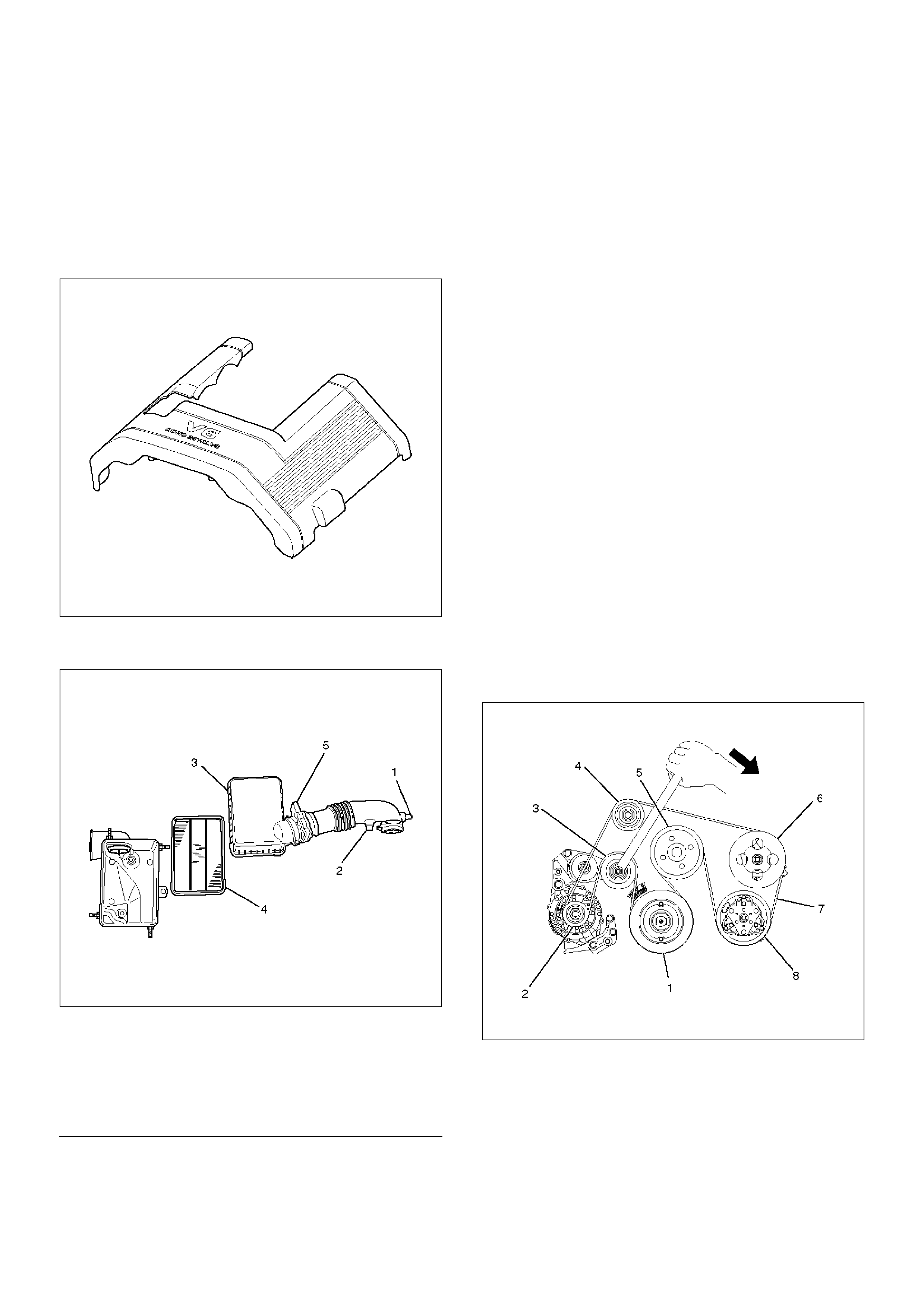
3. Remove engine cover from the dowels on the
common chamber.
F06RW018
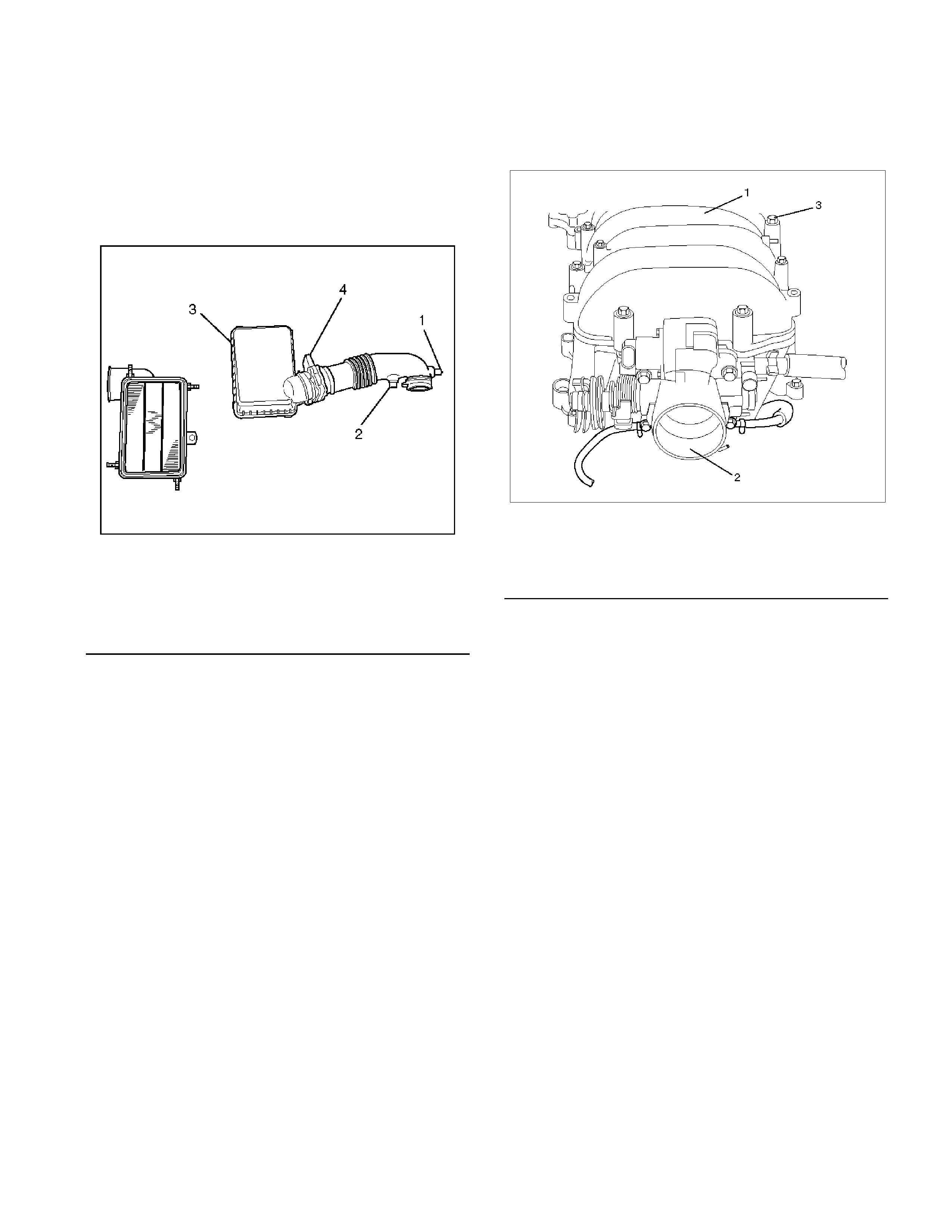
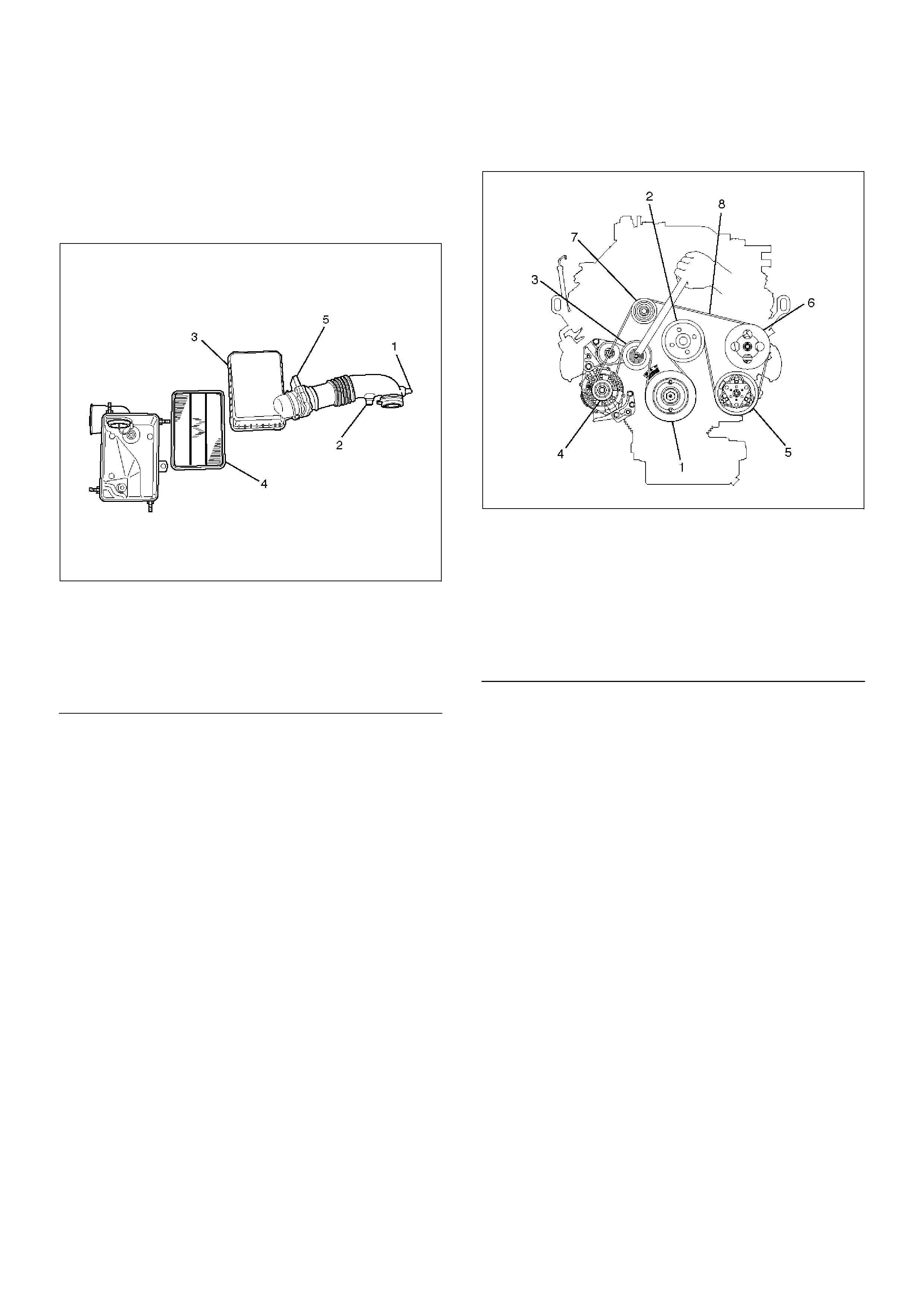
4. Remove air cleaner duct assembly (3) and air
cleaner element (4).
130RW001
EndOFC allout
NOTE: Disconnect the mass air flow (MAF) sensor
connector, intake air temperature (IAT) sensor
connector, and positive crankcase ventilation (PCV)
hose before hand the air cleaner duct assembly is
removed.
5. Disconnect following wiring connectors and bonding
cable:
• Manifold Absolute Pressure (MAP) sensor
• Vacuum Switching Valve (VSV) for Induction Air
Control Valve (IACV) actuator
• Ignition coils for left bank
• Fuel injectors for left bank
• Idle air control (IAC) valve
• Throttle position sensor (TPS)
• Bonding cable
• Others as necessitated
6. Disconnect following vacuum hoses:
• Brake master VAC
• Canister
• VSV for IACV actuator
• Duty solenoid valve
•PCV
7. Disconnect radiator upper and lower hoses
8. Remove engine harness from the cylinder head
cover.
9. Remove the upper fan guide.
10. Remove cooling fan and clutch assembly.
11. Remove drive belt by pushing down the auto
tensioner using spanner as illustrated.
F06RW019
Legend
(1) Positive Crankcase Ventilation Hose Connector
(2) Intake Air Temperature Sensor
(3) Air Cleaner Duct Assembly
(4) Air Cleaner Element
(5) Mass Air Flow Sensor
EndOFC allout
12. Remove power steering oil pump pulley.
13. Remove fan pulley and bracket assembly.
14. Remove idle pulley assembly.
15. Remove auto tensioner assembly.
16. Remove crankshaft pulley using 5–8840–0133–0
crankshaft holder.
17. Remove timing belt covers from the right bank side
to the left bank side in order.
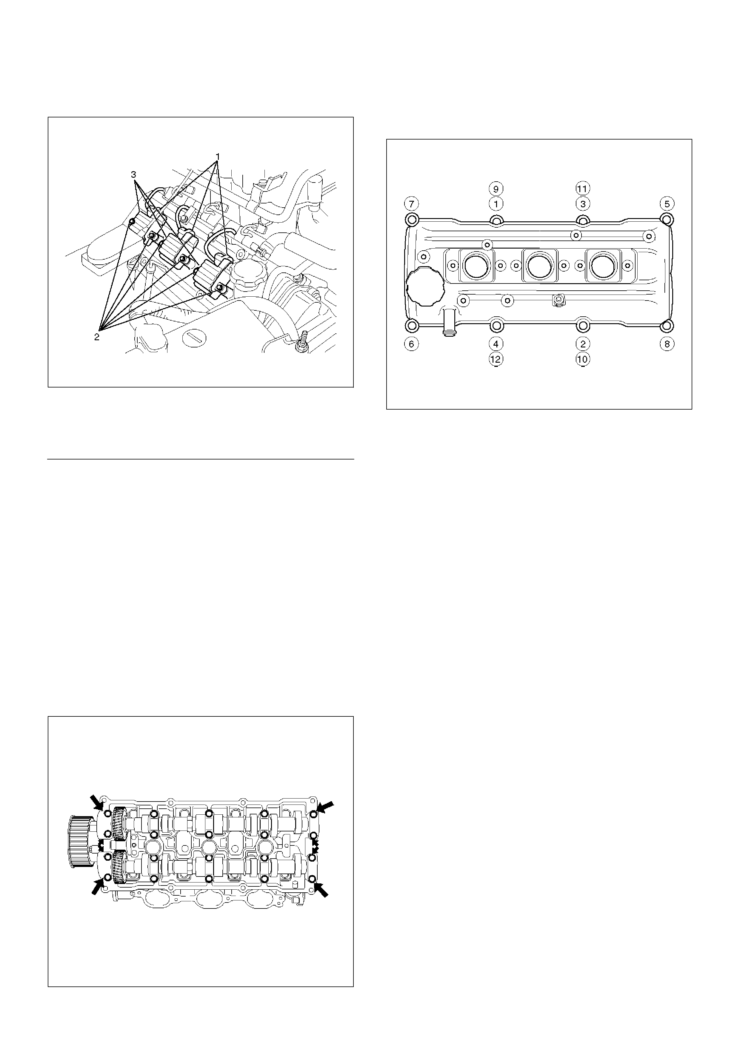
18. Remove ignition coil assemblies for the left side
bank.
060RW018
EndOFC allout
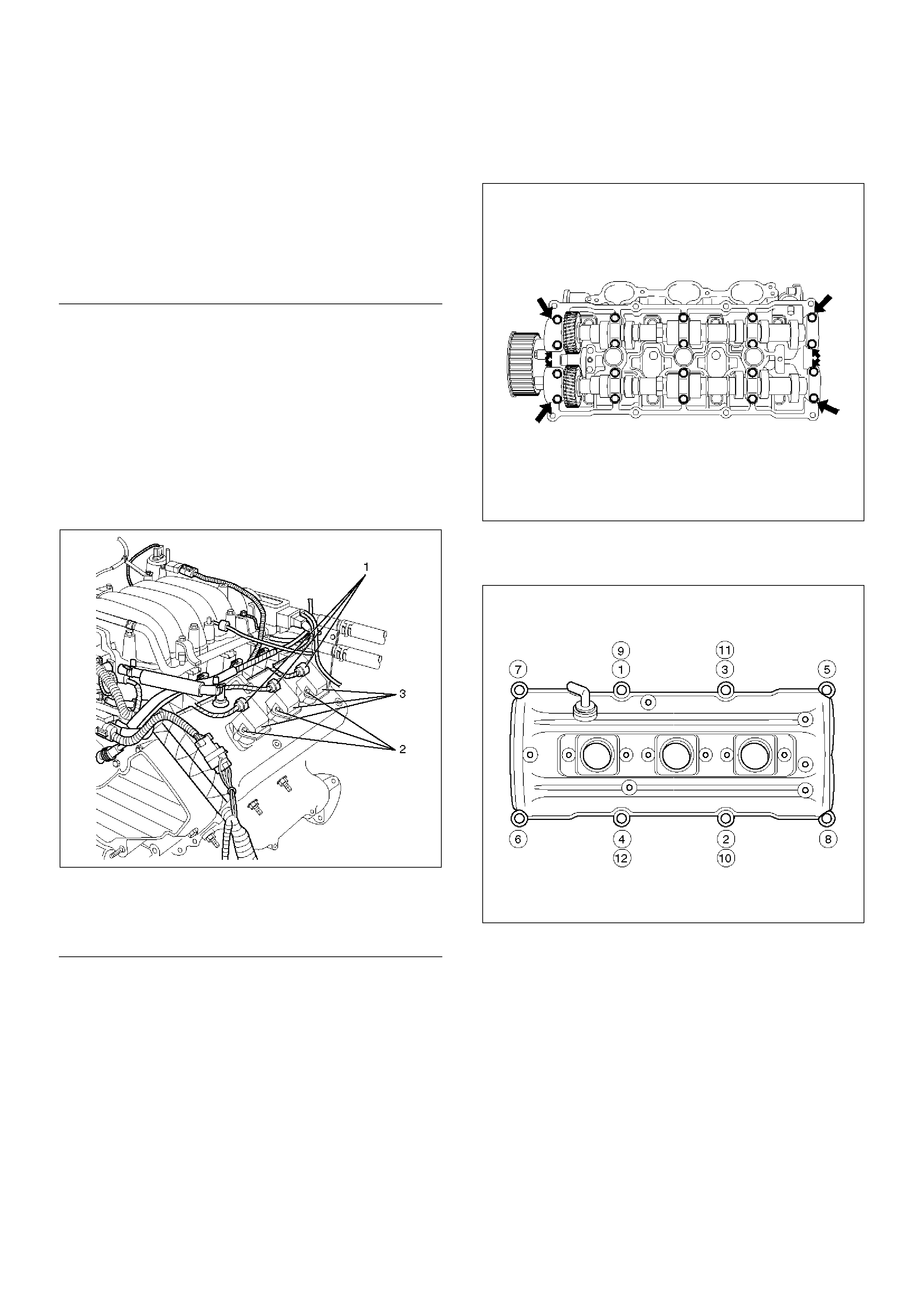
19. Remove cylinder head cover assembly.
Installation
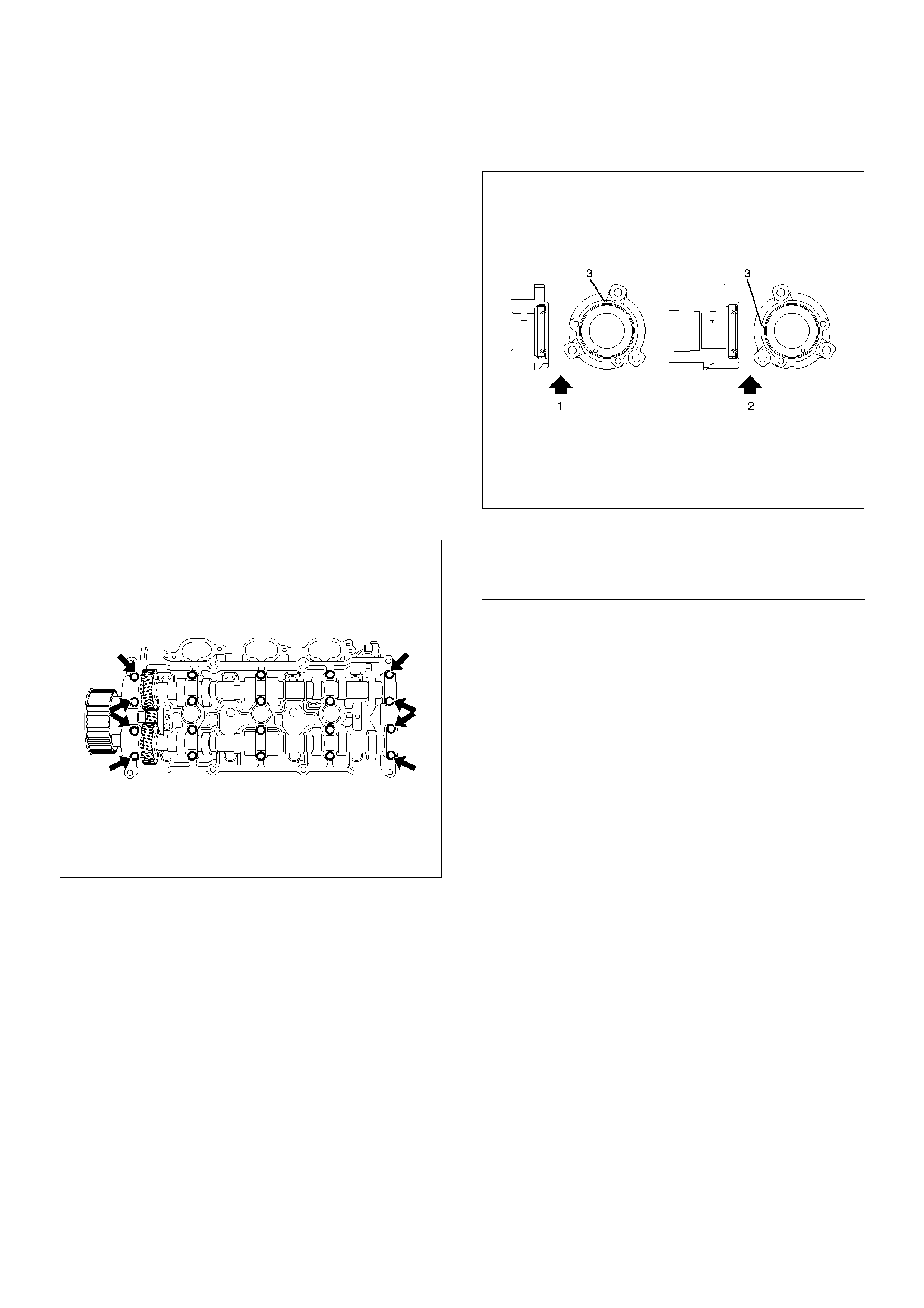
1. Install cylinder head cover.
• Clean the sealing surface of cylinder head and
cylinder head cover to remove oil and sealing
materials completely.
• Apply sealant (TB-1207B or equivalent) of bead
diameter 2-3 mm at eight place of arched area of
camshaft bracket on front and rear sides.
• The cylinder head cover must be installed within
5 minutes after sealant application to prevent
premature hardening of sealant.
014RW144
• Tighten bolts to the specified torque.
Torque : 9 N·m (0.9 Kg·m/78 lb in)
010RW008
2. Install ignition coil assemblies and tighten the fixing
bolts to the specified torque.
Torque : 4 N·m (0.4 Kg·m/35 lb in)
3. Install timing belt covers from left bank side to right
bank side, and tighten the fixing bolts and nut to the
specified torque.
Torque : 19 N·m (1.9 Kg·m/14 lb ft)
4. Install crankshaft pulley and tighten the fixing bolt
using 5–8840–0133–0 crankshaft holder to the
specified torque.
Torque : 167 N·m (17.0 Kg·m/123 lb ft)
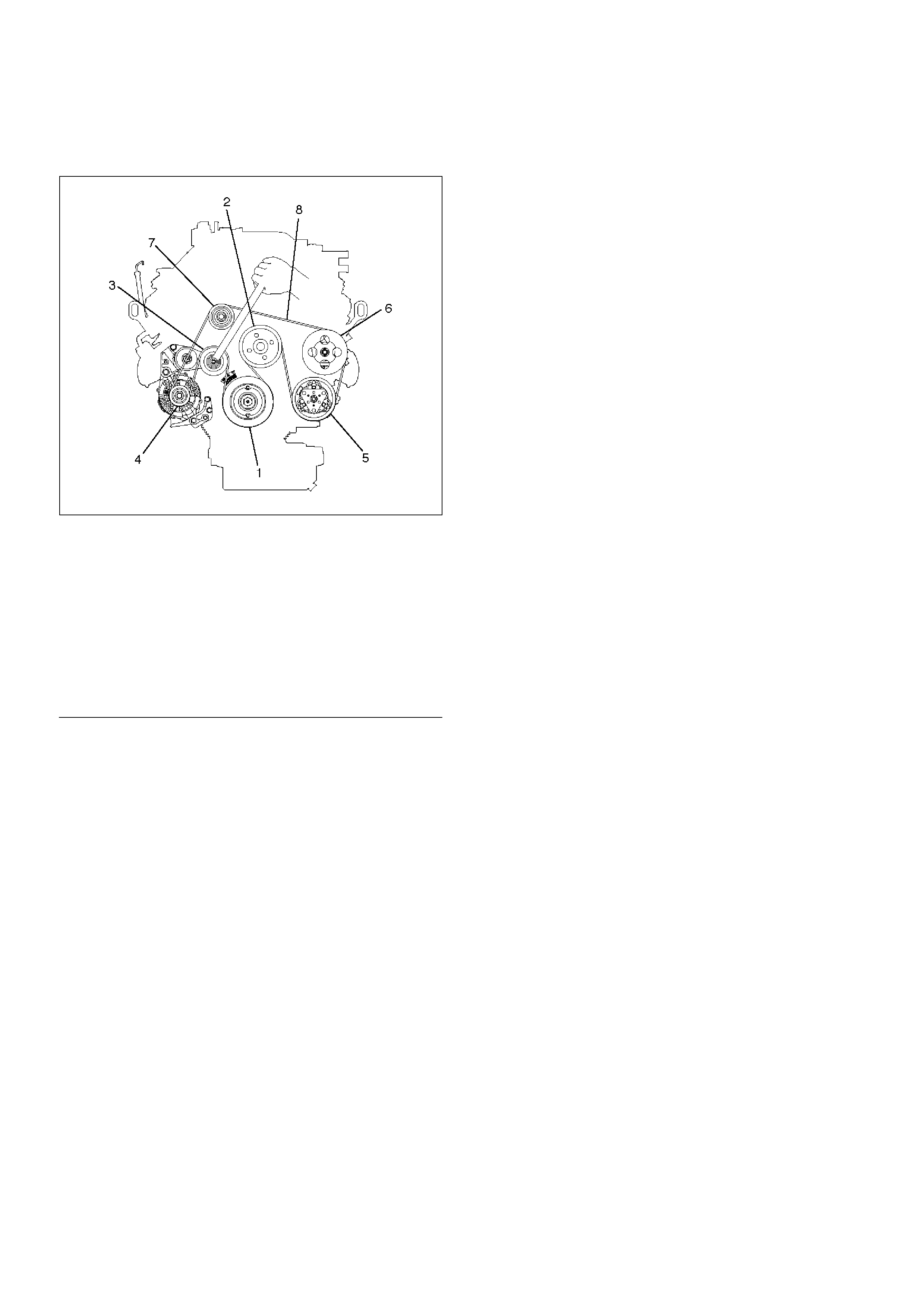
Legend
(1) Crankshaft Pulley
(2) Generator
(3) Auto Tensioner
(4) Idle Pulley
(5) Cooling Fan Pulley
(6) Power Steering Oil Pump
(7) Drive Belt
(8) Air Conditioner Compressor
Legend
(1) Ignition Coil Connectors
(2) Bolts
(3) Ignition Coil Assemblies

5. Install auto tensioner assembly and tighten the
fixing bolts to the specified torque.
Torque :
Shorter Bolt : 20 N·m (2.0 Kg·m/14 lb ft)
Longer Bolt : 39 N·m (4.0 Kg·m/29 lb ft)
6. Install idle pulley and bracket assembly and tighten
the fixing bolt to the specified torque.
Torque : 52 N·m (5.3 Kg·m/38 lb ft)
7. Install fan pulley and bracket assembly and tighten
the fixing bolts and nut to the specified torque.
Torque : 22 N·m (2.2 Kg·m/16 lb ft)
8. Install power steering oil pump pulley and tighten
the fixing bolt to the specified torque.
Torque : 78 N·m (8.0 Kg·m/58 lb ft)
9. Install drive belt by pushing down the auto tensioner
using spanner as shown in the removal step of drive
belt.
10. Install cooling fan and clutch assembly and tighten
the fixing bolts to the specified torque.
Torque : 10 N·m (1.0 Kg·m/87 lb in)
11. Install upper fan guide and clip both side and tighten
the fixing bolts to the specified torque.
Torque : 4 N·m (0.4 Kg·m/35 lb in)
12. Install engine harness and tighten the fixing bolts of
the retaining clip and bracket to the specified torque.
Torque : 4 N·m (0.4 Kg·m/35 lb in)
13. Connect radiator upper and lower hoses and clip
them securely.
14. Connect vacuum hoses of those which were
disconnected in the removal step.
15. Connect wiring connectors and bonding cable of
those which were disconnected in the removal step.
16. Install air cleaner element and air cleaner duct
assembly, and clip the both end securely.
17. Connect MAF sensor connector, IAT sensor
connector and PCV hose.
18. Install engine cover mating with the dowels.
Cylinder Head Cover RH
Removal
1. Disconnect battery ground cable.
2. Remove battery from the vehicle.
3. Drain engine coolant from faucet bottom of radiator.
4. Remove engine cover from the dowels on the
common chamber.
F06RW018
5. Remove air cleaner duct assembly (3) and air
cleaner element (4).
130RW001
EndOFC allout
NOTE: Disconnect the mass air flow (MAF) sensor
connector, intake air temperature (IAT) sensor
connector, and positive crankcase ventilation (PCV)
hose before hand the air cleaner duct assembly is
removed.
6. Disconnect following wiring connectors and bonding
cable:
• Exhaust Gas Recirculation (EGR) valve
• Fuel injectors for right bank
• Ignition coils for right bank
• Bonding cable
• Othres as necessitated
7. Disconnect radiator upper and lower hoses.
8. Remove engine harness from the cylinder head
cover.
9. Remove the upper fan guide.
10. Remove cooling fan and clutch assembly.
11. Remove drive belt by pushing down the auto
tensioner using spanner as illustrated.
F06RW019
EndOFC allout
12. Remove fan pulley and bracket assembly.
13. Remove idle pulley assembly.
14. Remove auto tensioner assembly.
15. Remove crankshaft pulley using 5–8840–0133–0
crankshaft holder.
16. Remove timing belt covers for right bank side.
Legend
(1) Positive Crankcase Ventilation Hose Connector
(2) Intake Air Temperature Sensor
(3) Air Cleaner Duct Assembly
(4) Air Cleaner Element
(5) Mass Air Flow Sensor
Legend
(1) Crankshaft Pulley
(2) Generator
(3) Auto Tensioner
(4) Idle Pulley
(5) Cooling Fan Pulley
(6) Power Steering Oil Pump
(7) Drive Belt
(8) Air Conditioner Compressor
17. Remove timing belt covers for right bank side.
060RW001
EndOFC allout
18. Remove ignition coil assemblies for the right side
bank.
19. Remove cylinder head cover assembly.
Installation
1. Install cylinder head cover.
• Clean the sealing surface of cylinder head and
cylinder head cover to remove oil and sealing
materials completely.
• Apply sealant (TB-1207B or equivalent) of bead
diameter 2-3 mm at eight place of arched area of
camshaft bracket on front and rear sides.
• The cylinder head cover must be installed within
5 minutes after sealant application before the
sealant hardens.
014RW143
• Tighten bolts in turn to the specified torque.
Torque : 8.8 N·m (0.9 Kg·m/78 lb in)
010RW007
2. Install ignition coil assemblies and tighten the fixing
bolts to the specified torque.
Torque : 4 N·m (0.4 Kg·m/35 lb in)
3. Install timing belt cover and tighten the fixing bolts
and nut to the specified torque.
Torque : 19 N·m (1.9 Kg·m/14 lb ft)
4. Install crankshaft pulley and tighten the fixing bolt
using 5–8840–0133–0 crankshaft holder to the
specified torque.
Torque : 167 N·m (17 Kg·m/123 lb ft)
5. Install auto tensioner assembly and tighten the
fixing bolts to the specified torque.
Torque :
Shorter Bolt : 20 N·m (2.0 Kg·m/14.8 lb ft)
Longer Bolt : 39 N·m (4.0 Kg·m/28.8 lb ft)
6. Install idle pulley assembly and tighten the fixing
bolt to the specified torque.
Torque : 52 N·m (5.3 Kg·m/38.4 lb ft)
7. Install fan pulley and bracket assembly and tighten
the fixing bolts and nut to the specified torque.
Torque : 22 N·m (2.2 Kg·m/16.2 lb ft)
8. Install drive belt by pushing down the auto tensioner
using spanner as shown in the removal step of drive
belt.
9. Install cooling fan clutch assembly and tighten the
fixing bolts to the specified torque.
Torque : 10 N·m (1.0 Kg·m/88.5 lb in)
10. Install upper fan guide and clip both side and tighten
the fixing bolts to the specified torque.
Torque : 4 N·m (0.4 Kg·m/35.4 lb in)
Legend
(1) Ignition Coil Connectors
(2) Bolts
(3) Ignition Coil Assemblies

11. Install engine harness and tighten the fixing bolts of
the retaining clip and brackets to the specified
torque.
Torque : 4 N·m (0.4 Kg·m/35.4 lb in)
12. Connect radiator upper and lower hoses and clip
them securely.
13. Connect wiring connectors and bonding cable of
those which were disconnected in the removal step.
14. Install air cleaner element and air cleaner duct
assembly, and the clip both end securely.
15. Connect MAF sensor connector, IAT sensor
connector and PCV hose.
16. Install engine cover mating with the dowels.
Common Chamber
Removal
1. Disconnect battery ground cable.
2. Remove the air cleaner duct assembly.
013RY00001
Legend
(1) Positive Crankcase Ventilation Hose Connector
(2) Intake Air Temperature Sensor
(3) Air Cleaner Duct As sembly
(4) Air Flow Sensor
3. Disconnect accelerator pedal cable from throttle
body and cable bracket.
4. Disconnect vacuum booster hose from common
chamber.
5. Disconnect connector from manifold absolute
pressure sensor, idle air control valve, throttle
position sensor, solenoid valve, electric vacuum
sensing valve, and EGR valve.
6. Disconnect vacuum hose on canister VSV and
positive crankcase ventilation hose, fuel rail
assembly with pressure control valve bracket.
7. Remove ventilation hose from throttle valve and
intake duct and remove water hose.
8. Remove the four throttle body fixing bolts.
9. Remove exhaust gas recirculation valve assembly
fixing bolt and nut on common chamber and
remove EGR valve assembly.
10. Remove two bolts from co mmon chamber rear
side for remove fuel hose bracket.
11. Remove common chamber four bolts and four nuts
then remove the common chamber.
025RW001
Legend
(1) Common Chamber
(2) Throttle Valve Assembly
(3) Bolt
Installation
1. Install throttle body and tighten bolts to the
specified torque.
Torque : (Bolt size M8)
25 N.m (2.6 kg·m/18 lb ft)
2. Install fuel hose bracket and tighten bolts to
specified torque.
Torque : 10 N.m (1.0 kg·m/89 lb in)
3. Install common chamber and tighten bolts and
nuts to the specified torque.
Torque :
Bolt : 18 N.m (1.8 kg-m/13 lb ft.)
Nut : 18 N.m (1.8 kg·m/13 lb ft)
4. Install ventilating hose to throttle valve and intake
duct.
5. Install exhaust gas recirculation valve assembly
and tighten bolt and nut to specified torque.
Torque : 25 N.m (2.5 kg·m/18 lb ft)
6. Connect vacuum hoses on canister VSV and
positive crankcase ventilation valve. Tighten bolts
for fuel rail assembly with pressure control valve
bracket to specified torqu e.
Torque : 25 N.m (2.5 kg·m/18 lb ft)
7. Connect each connector without fail.
8. Connect vacuum booster hose.
9. Connect accelerator pedal cable.
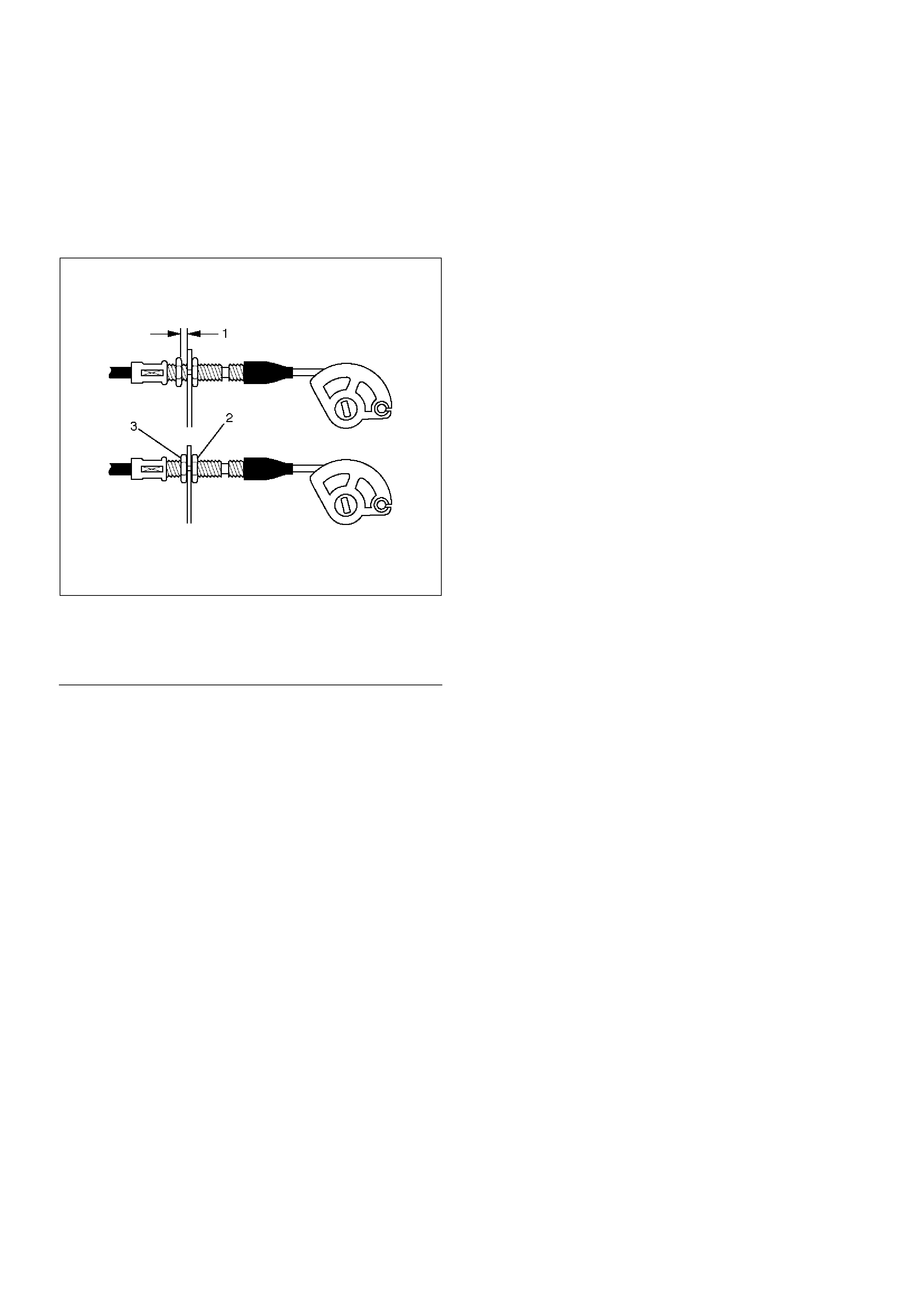
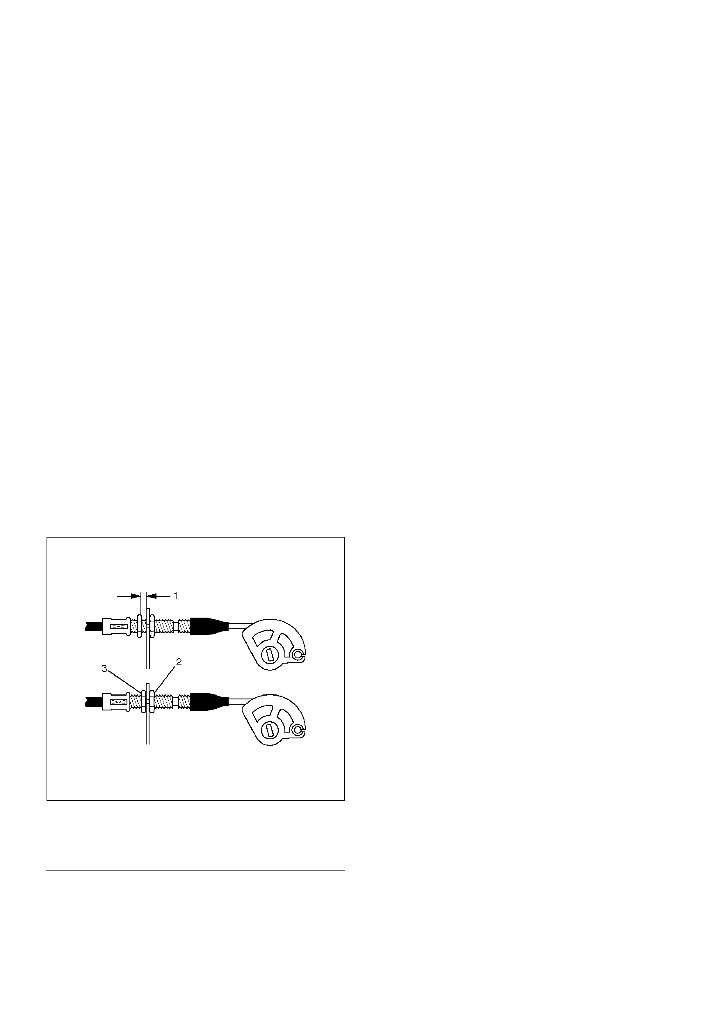
Accelerator pedal cable adjustment
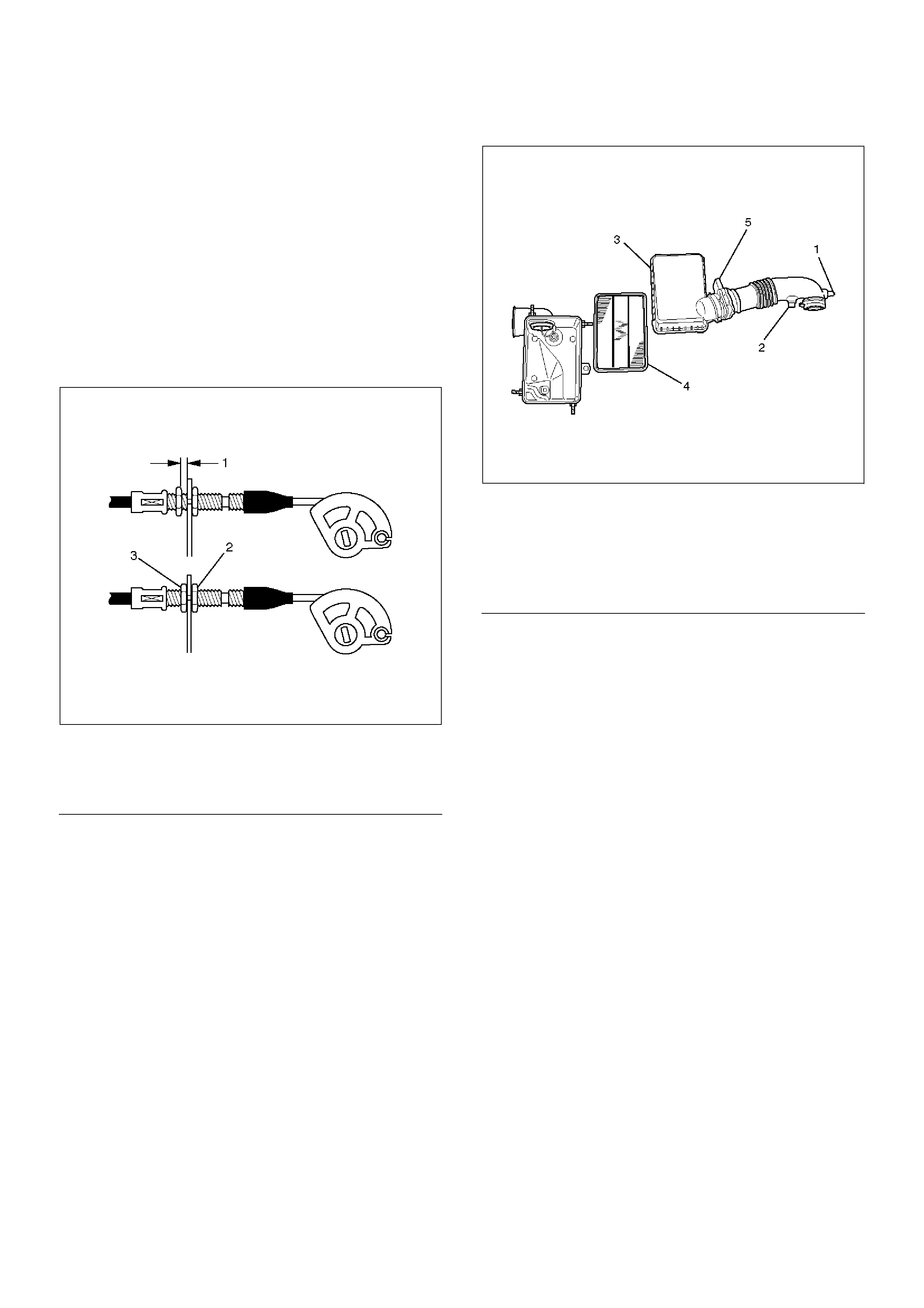
1. Loosen the adjusting nut and screw cap.
2. Pull outer cable while fully closing the throttle
valve.
3. Tighten adjusting nut and lock nut temporarily.
4. Loosen adjusting nut by three turns and tighten
lock nut.
Then manually operating the throttle valve,
make sure that the valve lever returns up to the
stopper screw.
If it does not reach the stopper screw, repeat
from step 1.
035RW004
EndOFC allout
10. Install air cleaner duct assembly.
130RW001
EndOFC allout
Legend
(1) Clearance
(2) Lock Nut
(3) Adjusting Nut
Legend
(1) Positive Crankcase Ventilation Hose Connector
(2) Intake Air Temperature Sensor
(3) Air Cleaner Duct Assembly
(4) Air Cleaner Element.
(5) Mass Air Flow Sensor
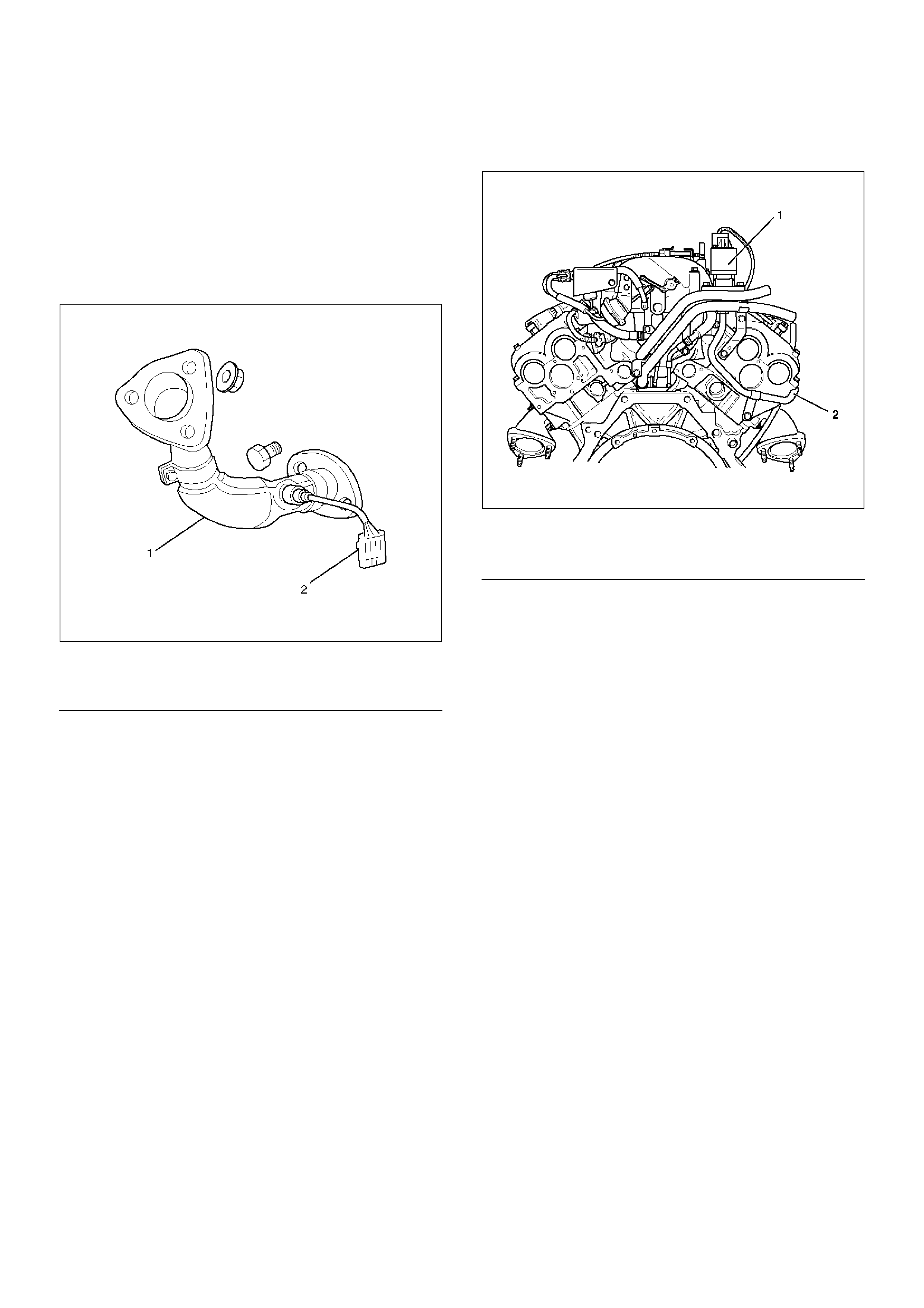
Exhaust Manifold LH
Removal
1. Disconnect battery ground cable.
2. Remove air cleaner duct assembly.
130RW001
EndOFC allout
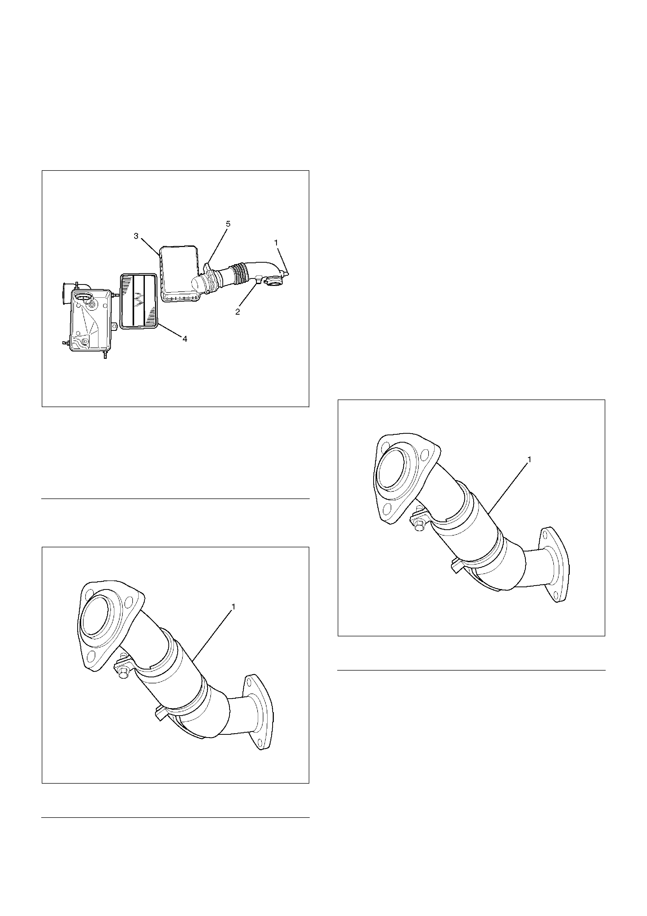
3. Remove exhaust front pipe three stud nuts from
exhaust side and two nuts from rear end of exhaust
front pipe.
150RW062
EndOFC allout
4. Remove heat protector two fixing bolts then the heat
protector.
5. Remove a bolt on engine LH side for air conditioner
(A/C) compressor bracket and loosen two bolts for
A/C compressor then move A/C compressor to front
side.
6. Remove exhaust manifold eight fixing nuts and
remove exhaust manifold from the engine.
Installation
1. Install exhaust manifold and tighten exhaust
manifold fixing nuts to the specified torque with new
nuts.
Torque: 57 N·m (5.8 Kg·m/42 lb ft)
2. Install heat protector.
3. Install exhaust front pipe and tighten three stud nuts
and two nuts to the specified torque.
Torque :
Stud nuts: 67 N·m (6.8 Kg·m/49 lb ft)
Nuts: 43 N·m (4.4 Kg·m/32 lb ft)
150RW062
EndOFC allout
4. Set A/C compressor to normal position and tighten
two bolts and a bolt to the specified torque.
Torque : 40 N·m (4.1 Kg·m/30 lb ft)
5. Install air cleaner duct assembly.
Legend
(1) Positive Crankcase Ventilation Hose Connector
(2) Intake Air Temperature Sensor
(3) Air Cleaner Duct Assembly
(4) Air Cleaner Element
(5) Mass Air Flow Sensor
Legend
(1) Exhaust Front Pipe LH
Legend
(1) Exhaust Front Pipe LH
Exhaust Manifold RH
Removal
1.Disconnect battery ground cable.
2.Remove torsion bar. Refer to removal procedure in
Front Suspension section.
3.Remove exhaust front pipe three stud nuts and two
nuts then disconnect exhaust front pipe.
150RW061
EndOFCallout
4.Remove heat protector two fixing bolts then the heat
protector.
5.Remove exhaust gas recirculation (EGR) pipe fixing
bolt and nut from exhaust manifold, remove a nut
from EGR valve and a bolt from rear side of cylinder
head for bracket of EGR pipe then remove the EGR
pipe.
056RW001
EndOFCallout
6.Remove exhaust manifold eight fixing nuts then the
exhaust manifold.
Installation
1.Install exhaust manifold and tighten bolts to the
specified torque.
Torque : 57 N·m (5.8 Kg·m/42 lb ft)
2.Install the EGR pipe, tighten bolt and nut on exhaust
manifold to specified torque.
Torque : 28 N·m (2.9 Kg·m/21 lb ft)
Tighten nut to EGR valve to the specified torque.
Torque : 44 N·m (4.5 Kg·m/33 lb ft)
Tighten the bolt for EGR pipe bracket to specified
torque.
Torque : 25 N·m (2.5 Kg·m/18 lb ft)
3.Install heat protector
4.Install exhaust front pipe and tighten three stud nuts
and two nuts to the specified torque.
Torque:
Stud nuts: 67 N·m (6.8 Kg·m/49 lb ft)
Nuts: 43 N·m (4.4 Kg·m/32 lb ft)
5.Install the torsion bar and readjust the vehicle
height. Refer to installation and vehicle height
adjustment procedure for Front Suspension.
Legend
(1) Exhaust Front Pipe RH
(2) O2 Sensor (for IGM)
Legend
(1) Exhaust Gas Recirculation (EGR) Valve
(2) EGR Pipe
Crankshaft Pulley
Removal
1. Disconnect battery ground cable.
2. Remove air cleaner assembly.
130RW001
EndOFC allout
3. Remove radiator upper fan shroud from radiator.
4. Move serpentine belt tensioner to loose side using
wrench then remove serpentine belt.
850RW001
EndOFC allout
5. Remove cooling fan assembly four fixing nuts, then
the cooling fan assembly.
6. Remove crankshaft pulley assembly using
J-8614-01 crankshaft holder, hold crankshaft pulley
then remove center bolt and pulley.
Installation
1. Install crankshaft pulley using J-8614-01 crankshaft
holder, hold the crankshaft pulley and tighten center
bolt to the specified torque.
Torque : 167 N·m (17.0 Kg·m/123 lb ft)
2. Install cooling fan assembly and tighten bolts/nuts to
the specified torque.
Torque : 22 N·m (2.2 Kg·m/16 lb ft) for fan pulley
and fan bracket.
Torque : 10 N·m (1.0 Kg·m/88.5 lb in) for fan and
clutch assembly.
3. Move serpentine belt tensioner to loose side using
wrench, then install serpentine belt to normal
position.
4. Install radiator upper fan shroud.
5. Install air cleaner assembly.
Legend
(1) Positive Crankcase Ventilation Hose Connector
(2) Intake Air Temperature Sensor
(3) Air Cleaner Duct Assembly
(4) Air Cleaner Element
(5) Mass Air Flow Sensor
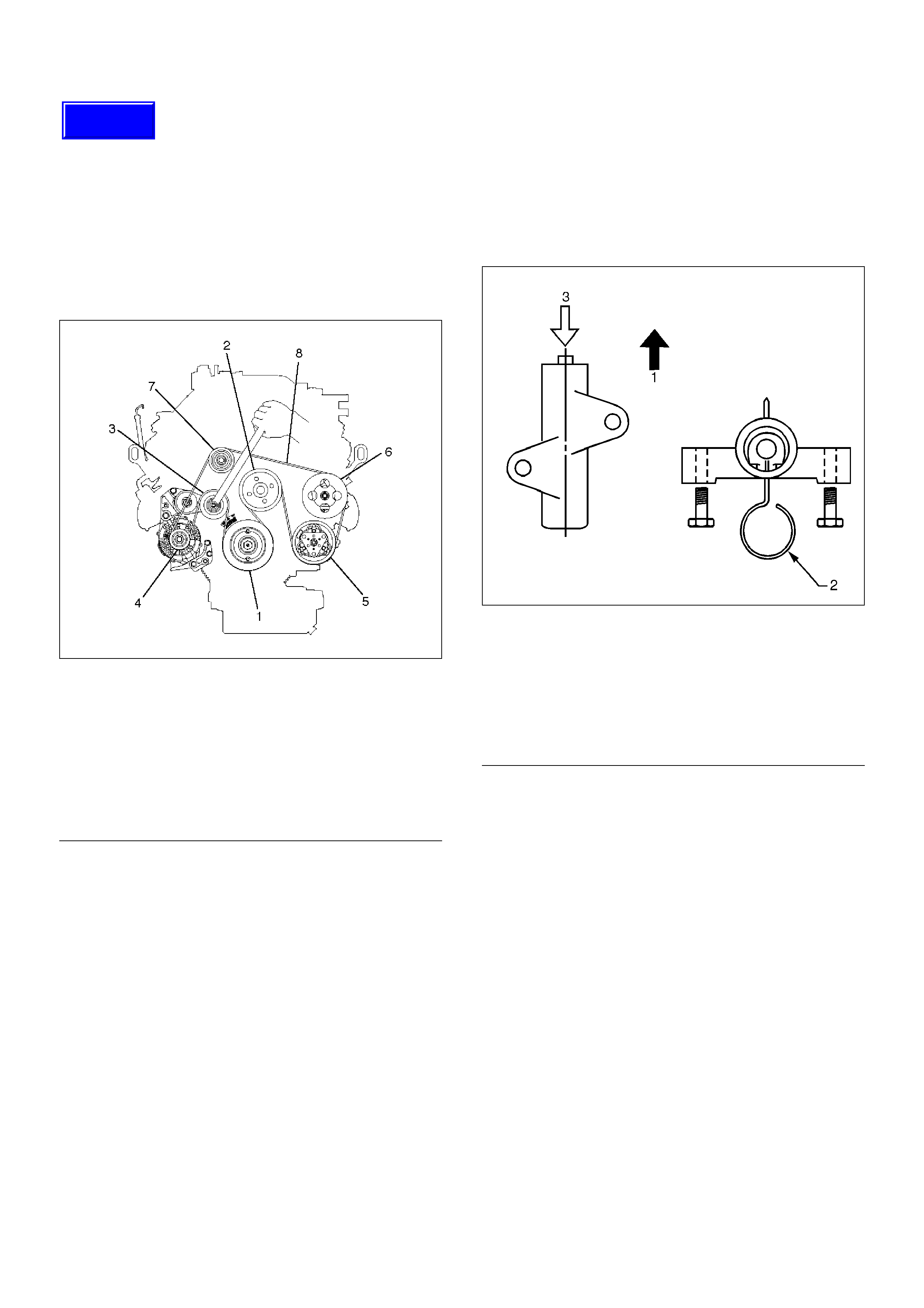
Legend
(1) Crankshaft Pulley
(2) Cooling Fan Pulley
(3) Tensioner
(4) Generator
(5) Air Conditioner Compressor
(6) Power Steering Oil Pump
(7) Serpentine Belt
Timing Belt - Broken Belt
Removal
1. Disconnect battery ground cable.
2. Remove air cleaner assembly.
3. Remove radiator upper fan shroud from radiator.
4. Move drive belt tensioner to loose side using
wrench then remove drive belt.
850RW001
EndOFCallout
5. Remove cooling fan assembly four nuts, then the
cooling fan assembly.
6. Remove cooling fan drive pulley assembly.
7. Remove idle pulley assembly.
8. Remove serpentine belt tensioner assembly.
9. Remove power steering pump assembly.
10. Remove crankshaft pulley assembly using 5–8840–
0133–0 crankshaft holder, hold crankshaft pulley
remove center bolt, then the pulley.
11. Remove right side timing belt cover then left side
timing belt cover.
12. Remove lower timing belt cover
13. Remove timing belt tensioner.
CAUTION: The prevent air entering the oil chamber.
The tensioner must be stored with the rod facing
upward.
014R100020
EndOFCallout
14. Remove broken timing belt.
15.Remove the cylinder head covers - refer to 6A-24
NOTE: NEW BELT CARE
1. Do not bend or twist the new belt, otherwise its
core could be damaged. The belt should not be
bent at a radius less than 30 mm.
2. Do not allow oil or other chemical substances to
come in contact with the belt. They will shorten
the life.
3. Do not attempt to pry or stretch the belt with a
screw driver or any other tool during
installation.
4. Store timing belt in a cool and dark place. Never
expose the belt to direct sunlight or heat.
Legend
(1) Crankshaft Pulley
(2) Cooling Fan Pulley
(3) Tensioner
(4) Generator
(5) Air Conditioner Compressor
(6) Power Steering Oil Pump
(7) Drive Belt
Legend
(1) Up Side
(2) Down Side
(3) Direction For Installation
(4) Locking Pin
(5) Apply a force of 980 N (220 lb) when
compressing the pusher rod.
Techline
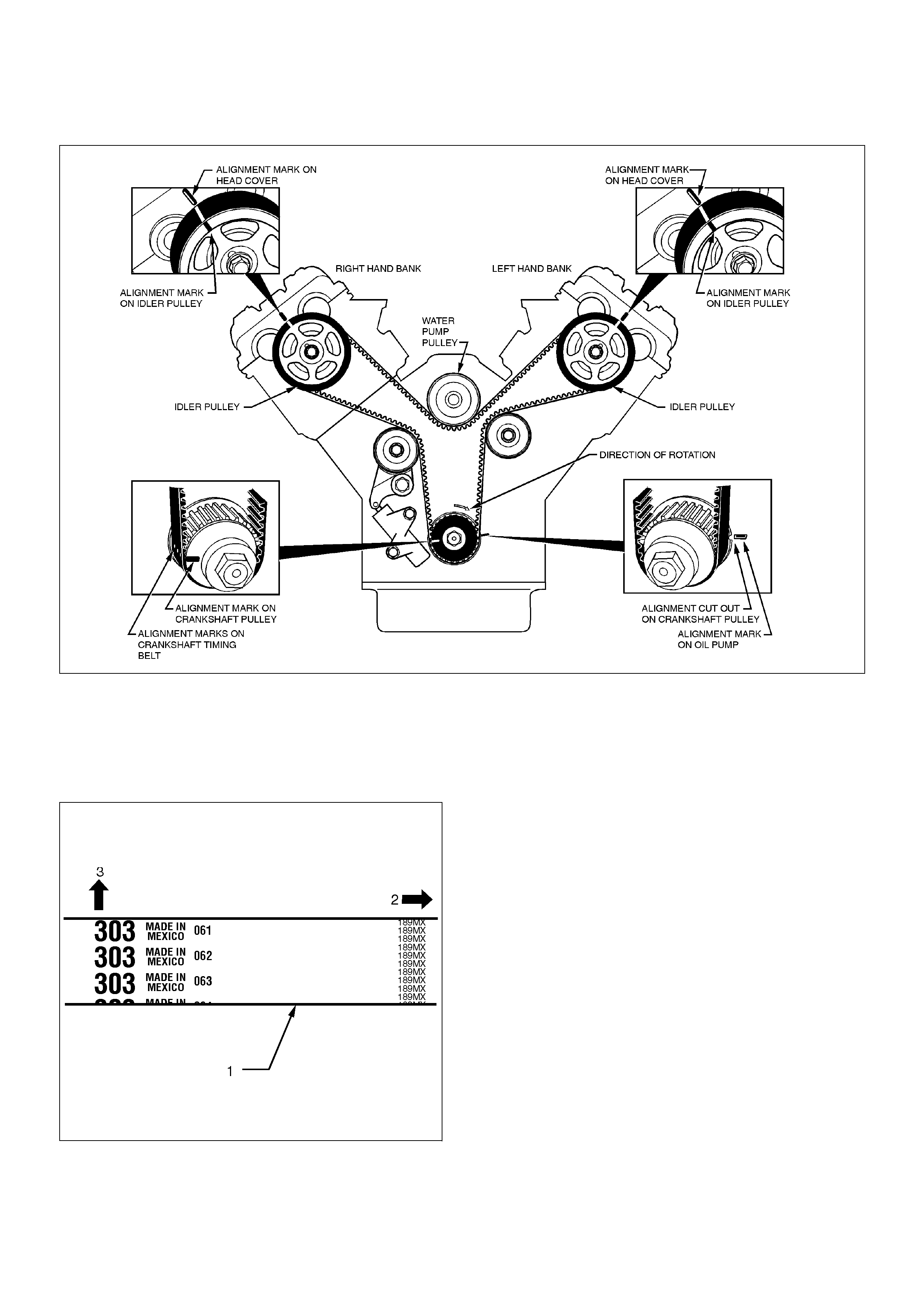
Installation
014R100015
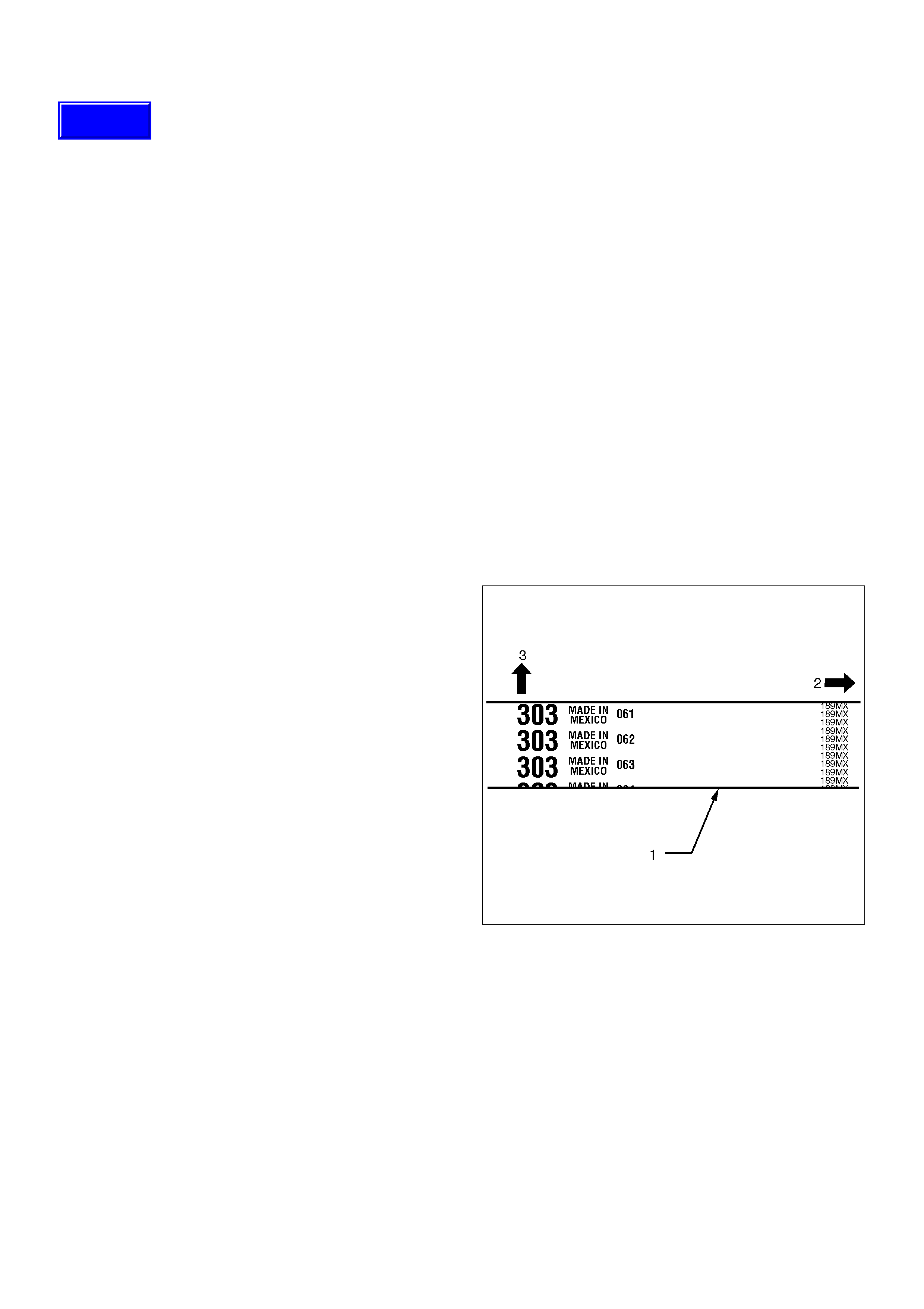
NOTE: For correct belt installation, the lettering on
the belt must be able to be read as viewed from the
front of the vehicle. Any attempt to use belts with
different markings will void these service
procedures.
014RW006
Legend
(1) Timing Belt
(2) Engine Rotation Direction
(3) Cylinder Head Side
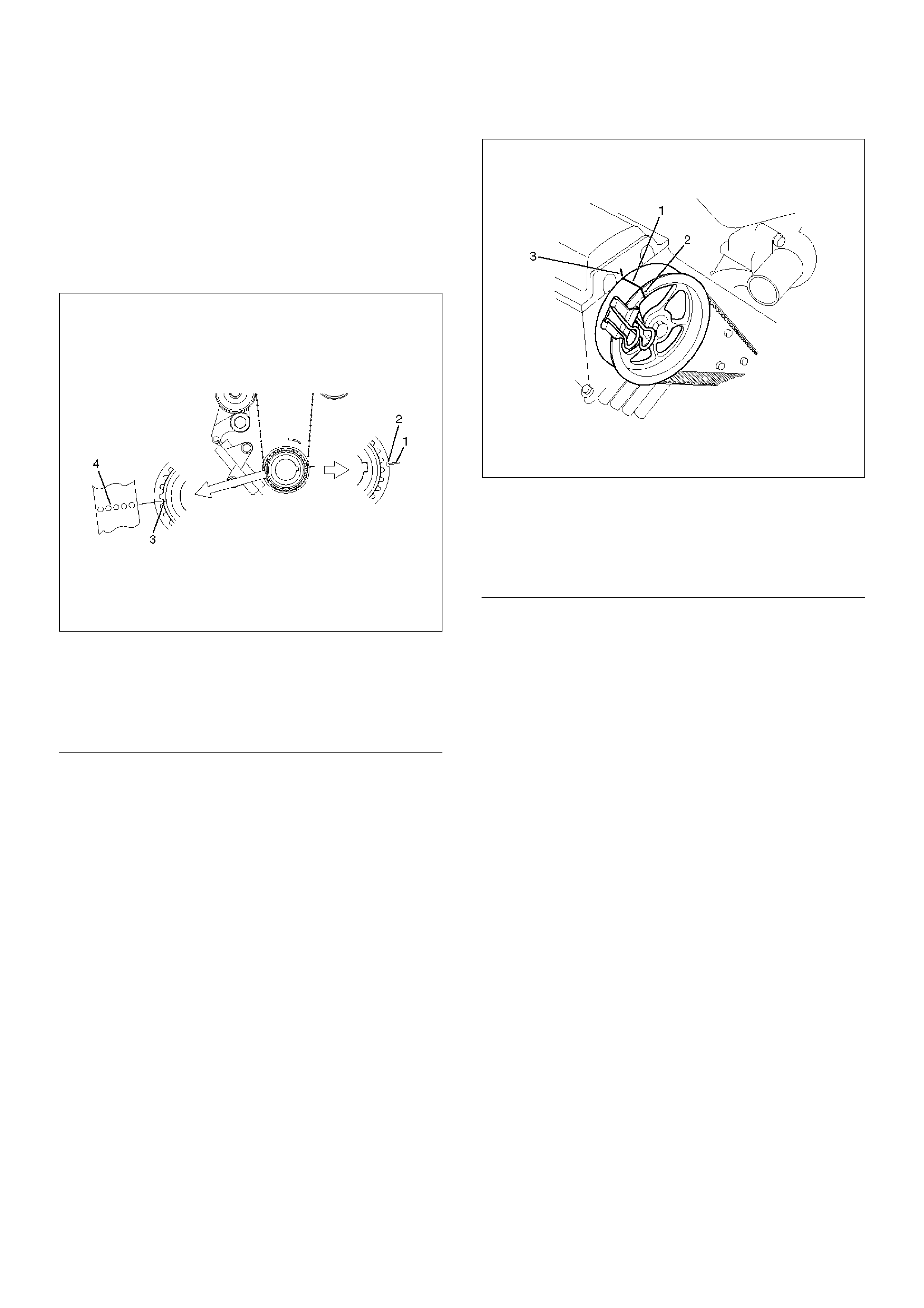
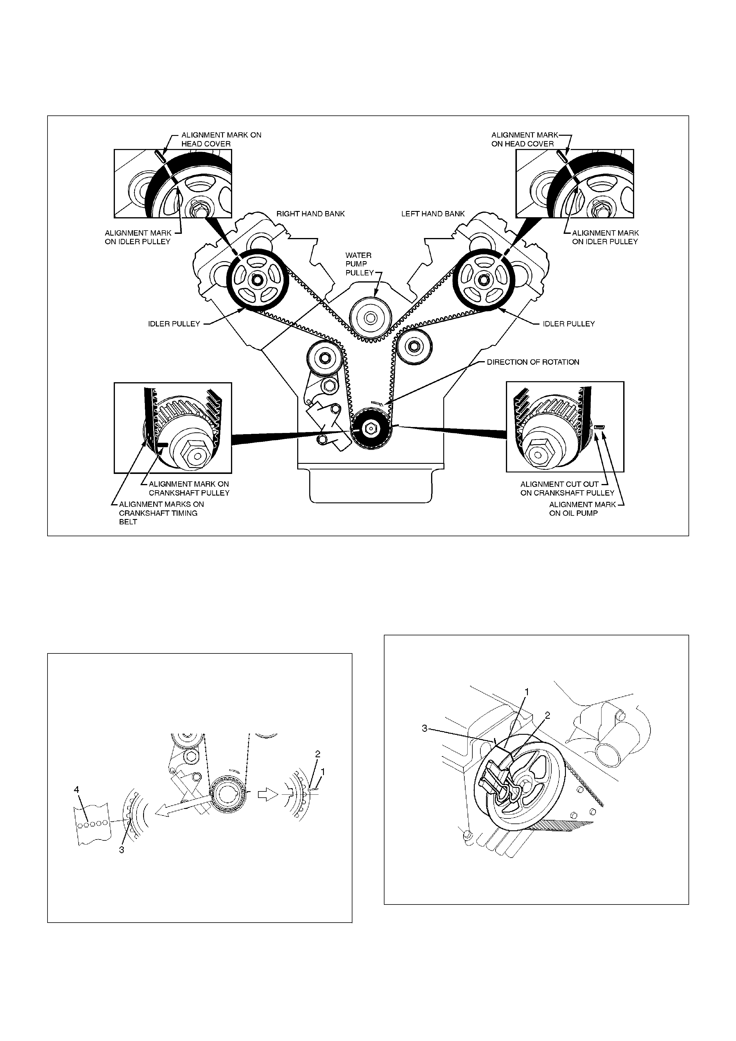
1. Install timing belt.
a Align the mark (notch) of crankshaft timing
pulley (2) with mark on oil pump (1).
Align the mark (groove) on the crankshaft timing
pulley (3) with alignment mark (white dots line)
on the timing belt (4).
When timing marks are aligned, No.2 piston will
be on Top Dead Center.
014RW003
EndOFCallout
b Rotate the camshaft drive gear pulley on the
right-hand bank to position the cam lobes for #1
cylinder as shown in the diagram on page xxx-
The alignment mark on the Camshaft Drive
Gear pulley should be at the 12o’clock position
relative to the cylinder head-block mounting
face.
c Align the alignment mark (white line) on the
timing belt (1) with alignment mark on the RH
bank camshaft drive gear pulley (2) (on the left
side as viewed from the front of the vehicle) and
put the timing belt on the camshaft drive gear
pulley.
Secure the belt with a double clip or equivalent
clip.
014RW00004
EndOFCallout
d Rotate the camshaft drive gear pulley on the
left-hand bank to position the cam lobes for #2
cylinder as shown in the diagram on page xxx-
The alignment mark on the Camshaft Drive
Gear pulley should be at the 12o’clock position
relative to the cylinder head-block mounting
face.
e Align the alignment mark (white line) on the
timing belt (1) with alignment mark on the RH
bank camshaft drive gear pulley (2) (on the left
side as viewed from the front of the vehicle) and
put the timing belt on the camshaft drive gear
pulley.
Secure the belt with a double clip or equivalent
clip.
f When aligning the timing marks, use a wrench
to turn the camshaft drive gear pulley, then set
the timing mark between timing belt and
camshaft drive gear pulley and put the timing
belt on the camshaft drive gear pulley.
Secure the belt with a double clip or equivalent
clip.
Legend
(1) Alignment Mark on Oil Pump
(2) Groove on Crankshaft Timing Pulley
(3) Alignment Mark on Crankshaft Timing Pulley
(4) Alignment Mark on Timing Belt
Legend
(1) Alignment Mark on Timing Belt (White line).
(2) Alignment Mark on Camshaft Drive Gear
Pulley.
(3) Alignemnt Mark on Cylinder Head Cover RH.
NOTE: It is recommended for easy installation that the
belt be secured with a double clip or equivalent clip after
it is installed the timing belt to each pulley.
014RW00005
EndOFCallout
g Install crankshaft pulley temporarily and tighten
center bolt by hand (do not use a wrench).
Turn the crankshaft pulley clockwise to give
some belt slack between the crankshaft timing
pulley and the RH bank camshaft drive gear
pulley.
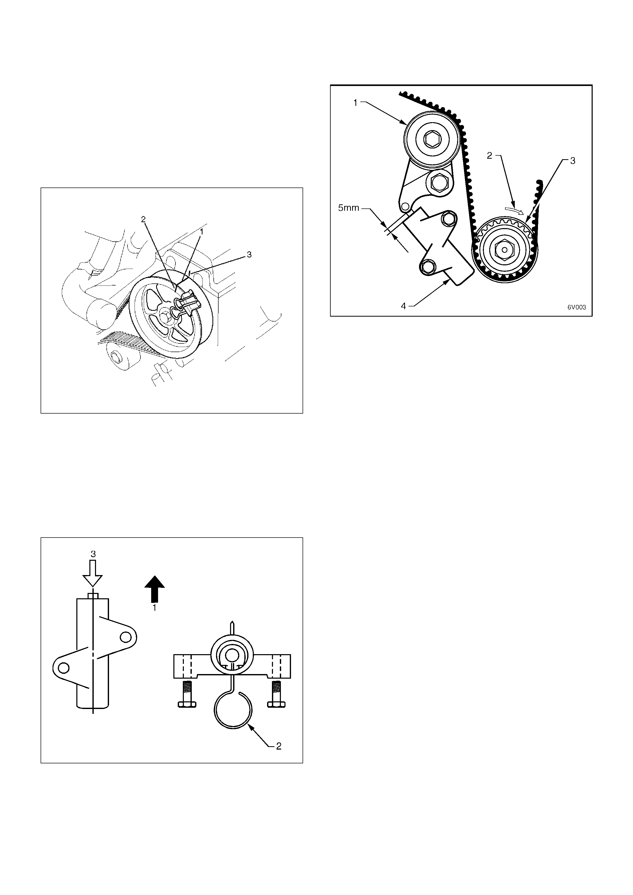
NOTE: When reusing the tensioner, compress the
tensioner rod with approximately 980N force and
insert a holding pin (1.4 mm piano wire).
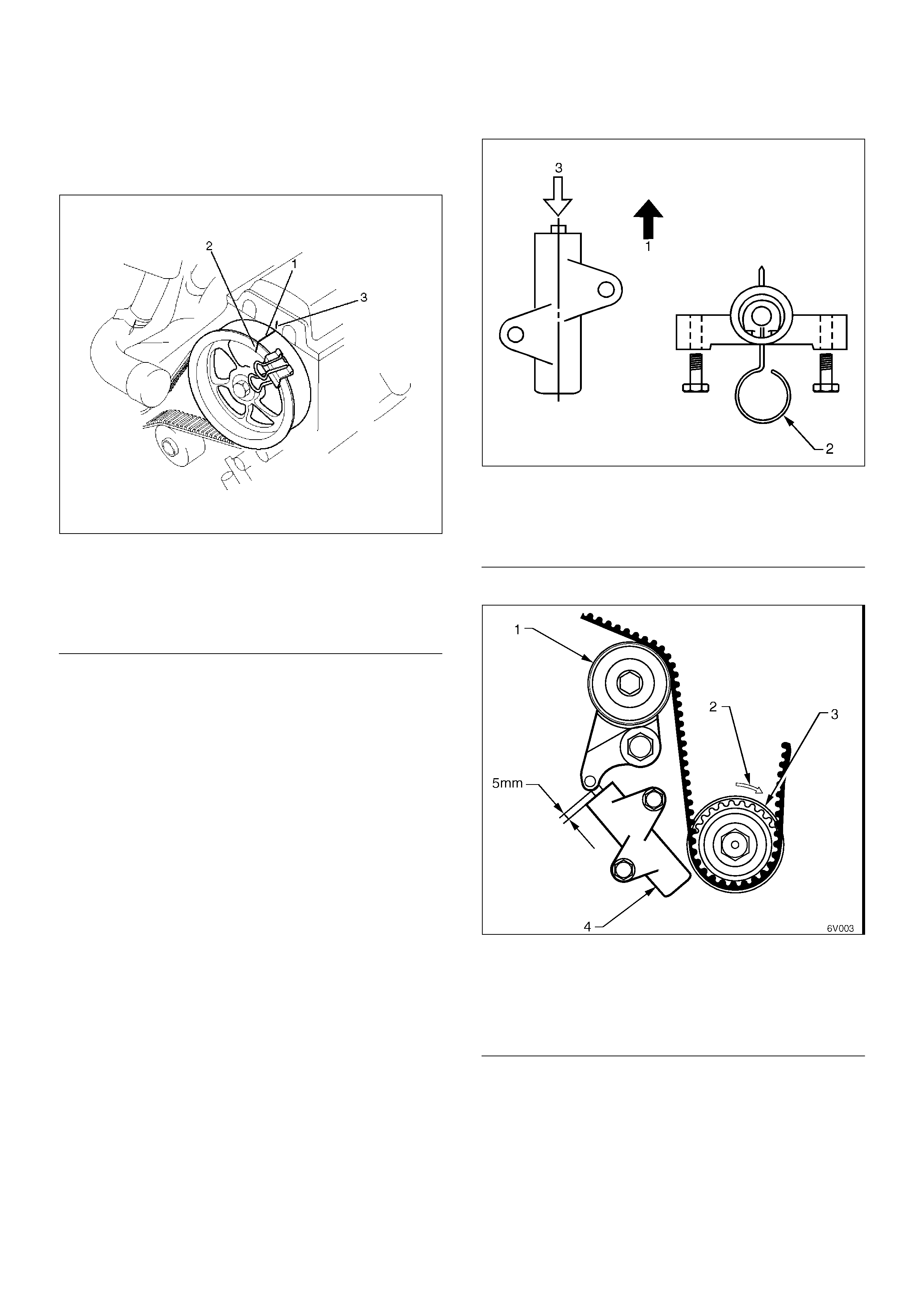
2. Install timing belt tensioner and tighten bolt to the
specified torque.
Torque : 25 N·m
a Install the tensioner while pushing the tension
pulley to the belt.
b Pull out pin from the tensioner.
NOTE: After release the push rod from the locking
pin, the rod projection is approximate 5 mm.
014R100020
dOFCallout
014R100032
EndOFCallout
c Remove double clips or equivalent clips, from
timing belt pulleys.
Turn the crankshaft pulley by six turns and
check for timing mark alignment.
NOTE: The crankshaft pulley timing mark, oil pump
cover timing mark and camshaft lobes will be in
their timing setting positions every six (6)
crankshaft revolutions.
Legend
(1) Alignment Mark on Timing Belt (White line).
(2) Alignment Mark on Camshaft Drive Gear
Pulley.
(3) Alignemnt Mark on Cylinder Head Cover LH.
Legend
(1) Direction for Installation
(2) Locking Pin
(3) Apply 980 N to compress the tensioner rod
Legend
(1) Tensioner Pulley
(2) Crankshaft Pulley Rotation Direction
(3) Crankshaft Pulley
(4) Tension Assembly
NOTE: The markings on the timing belt are for
installation only and will not realign every six turns.
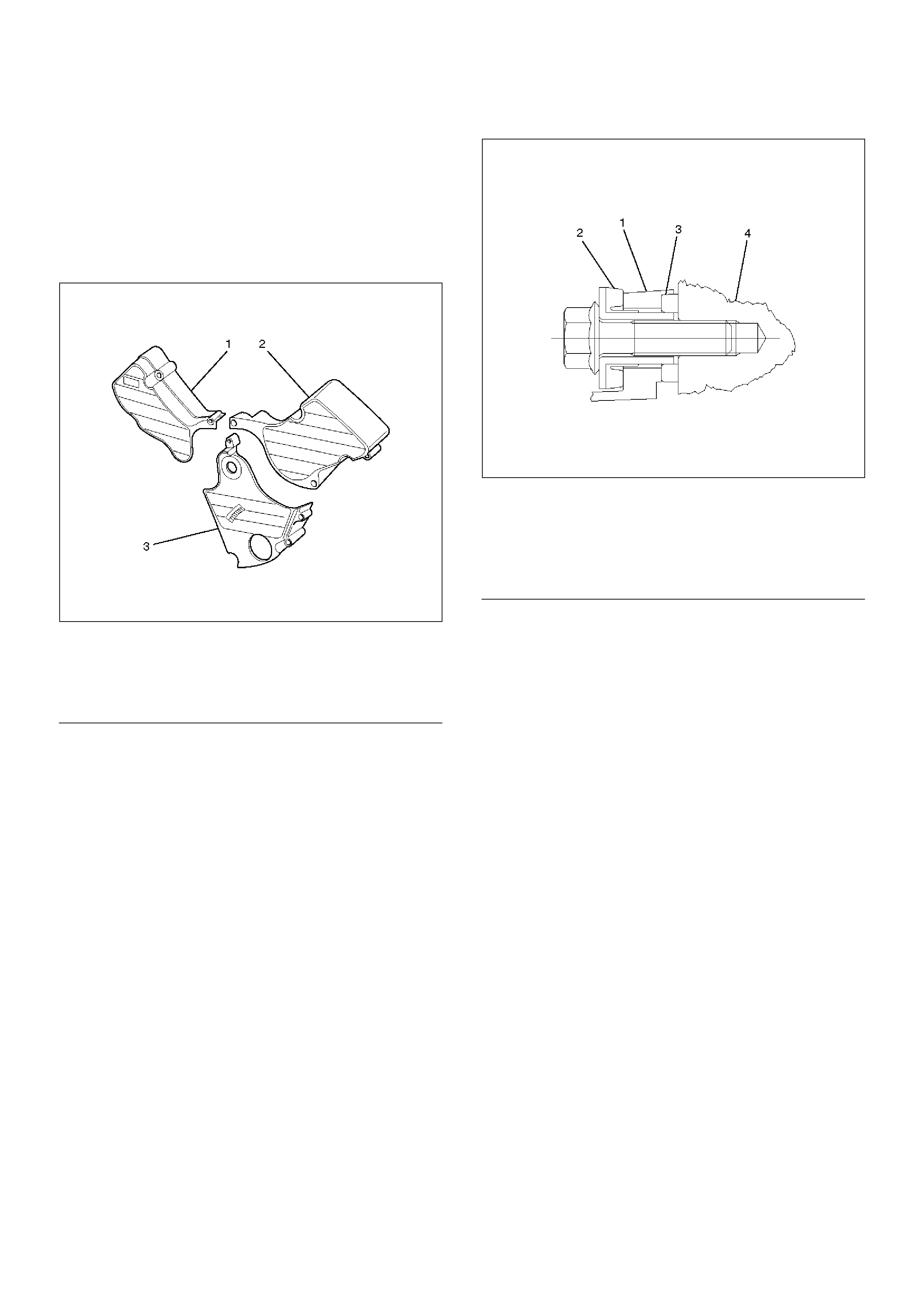
3. Install timing belt covers
Remove crankshaft pulley that was installed in step
1 item 5.
Tighten bolts to the specified torque.
Torque: 19 N·m
020RW004
EndOFCallout
020RW003
EndOFCallout
4. Install crankshaft pulley using 5–8840–0133–0, hold
the crankshaft pulley and tighten center bolt to the
specified torque.
Torque : 167 N·m
5. Install fan pulley bracket and tighten fixing bolts to
the specified torque.
Torque : 22 N·m
6. Install power steering pump assembly and tighten to
the specified torque.
Torque :
M8 bolt : 22 N·m
M10 bolt : 46 N·m
7. Install cooling fan assembly and tighten bolts/nuts to
the specified torque.
Torque : 22 N·m for fan pulley and fan bracket.
Torque : 10 N·m for fan and clutch assembly.
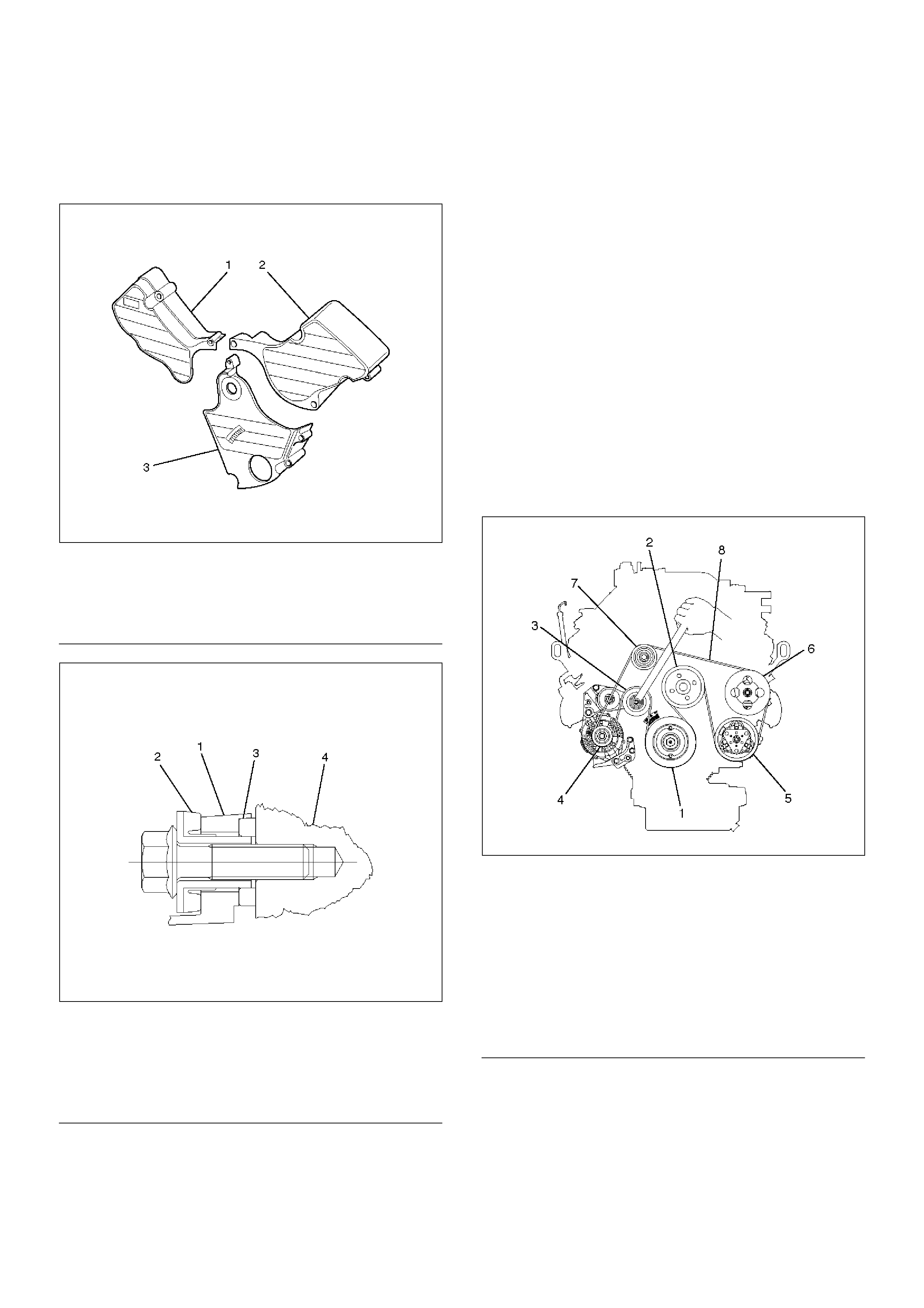
Legend
(1) Timing Belt Cover RH
(2) Timing Belt Cover LH
(3) Timing Belt Cover Lower
Legend
(1) Timing Belt Cover
(2) Rubber Bushing
(3) Sealing Rubber
(4) Cylinder Body
8. Move drive belt tensioner to loose side using
wrench, then install drive belt to normal position.
850RW001
EndOFCallout
9. Install radiator upper fan shroud.
10. Install air cleaner assembly.
Legend
(1) Crankshaft Pulley
(2) Cooling Fan Pulley
(3) Auto Tensioner
(4) Generator
(5) Air Conditioner Compressor
(6) Power Steering Oil Pump
(7) Idle Pulley
(8) Drive Belt
Timing Belt Replacement - Service Operation
Removal
1.Follow steps 1) through to 12) of the Timing Belt
Replacement - Broken Belt procedure - refer 6A-34
2. Rotate the crankshaft until the following marks are
aligned:
• The mark (notch) of crankshaft timing pulley (2) with
mark on oil pump (1).
• The alignment mark on the RH bank camshaft drive
gear pulley (2) to the alignment mark of the cylinder
head cover RH (3).
• The alignment mark on the LH bank camshaft drive
gear pulley (2) to the alignment mark of the cylinder
head cover LH (3).
NOTE: It It may require up to three revolutions of
the crankshaft to achieve alignment of all marks.
3. Remove the timing belt tensioner and carefully
remove the timing belt, ensuring the Camshaft
Drive Gear Pulleys do not turn.
Installation
NOTE:
1. Do not bend or twist the belt, otherwise its core
could be damaged. The belt should not be bent
at a radius less than 30 mm.
2. Do not allow oil or other chemical substances to
come in contact with the belt.
3. Do not attempt to pry or stretch the belt with a
screw driver or any other tool during
installation.
4. Store timing belt in a cool and dark place. Never
expose the belt to direct sunlight or heat.
NOTE:
For correct belt installation, the lettering on the
belt must be able to be read as viewed from the
front of the vehicle.
Any attempt to use belts with different markings to
those shown below will void these service
procedures.
014RW006
.
Legend
(1) Timing Belt
(2) Engine Rotation Direction
(3) Cylinder Head Side
Techline
Installation
014R100015
1. Ensure that the alignment marks on the crankshaft
and camshaft drive gear pulleys are aligned with
their respective marks as shown above.
2. Align the mark (groove) on the crankshaft timing
pulley (3) with alignment mark (white dots line) on
the timing belt (4)
3. Align the alignment mark (white line) on the timing
belt (1) with alignment mark on the RH bank
camshaft drive gear pulley (2) and put the timing
belt on the camshaft drive gear pulley. Secure the
belt with a double clip or equivalent clip.
4. Align the alignment mark (white line) on the timing
belt (1) with the alignment mark on the LH bank
camshaft drive gear pulley (2).
5. When aligning the timing marks, use a wrench to
turn the camshaft drive gear pulley, and put the
timing belt on the camshaft drive gear pulley.
Secure the belt with a double clip or equivalent clip.
6. Install crankshaft pulley temporarily and tighten
center bolt by hand (do not use a wrench).
7. Turn the crankshaft pulley clockwise to give some
belt slack between the crankshaft timing pulley and
the RH bank camshaft drive gear pulley.
8. Compress and pin the timing belt tensioner push
rod, then install timing belt tensioner and tighten bolt
to the specified torque.
Torque : 25 N·m
9. Remove the timing belt tensioner push rod locking
pin, and ensure that the push rod projection is about
5 mm., as shown above.EndOFCallout
10. Remove double clips or equivalent clips, from timing
belt pulleys.
11. Turn the crankshaft pulley by three turns and check
for timing mark alignment.
NOTE: The timing marks on the belt are for initial
installation only. Due to the gear ratio between the
camshaft drive gear pulley and the camshaft driven
gear, the belt markings cannot be used to recheck
timing accuracy.
Legend
(1) Direction for Installation
(2) Locking Pin
(3) Apply 980 N to compress the tensioner rod
Legend
(1) Tensioner Pulley
(2) Crankshaft Pulley Rotation Direction
(3) Crankshaft Pulley
(4) Tensioner Assembly
12. Install timing belt cover. and tighten bolts to the
specified torque.
Torque: 19 N·m (1.9 kg·m/14 lb ft)
020RW004
EndOFCallout
020RW003
EndOFCallout
13. Install crankshaft pulley using 5–8840–0133–0, hold
the crankshaft pulley and tighten center bolt to the
specified torque.
Torque : 167 N·m (17.0 kg·m/123 lb ft)
14. Install fan pulley bracket and tighten fixing bolts to
the specified torque.
Torque : 22 N·m (2.2 kg·m/16 lb ft)
15. Install power steering pump assembly and tighten to
the specified torque.
Torque :
M8 bolt : 22 N·m (2.2 kg·m/16 lb ft)
M10 bolt : 46 N·m (4.7 kg·m/34 lb ft)
16. Install cooling fan assembly and tighten bolts/nuts to
the specified torque.
Torque : 22 N·m (2.2 kg·m/16 lb ft) for fan pulley
and fan bracket.
Torque : 10 N·m (1.0 kg·m/87 lb in) for fan and
clutch assembly.
17. Move drive belt tensioner to loose side using
wrench, then install drive belt to normal position.
850RW001
EndOFCallout
18. Install radiator upper fan shroud.
19. Install air cleaner assembly.
Legend
(1) Timing Belt Cover RH
(2) Timing Belt Cover LH
(3) Timing Belt Cover Lower
Legend
(1) Timing Belt Cover
(2) Rubber Bushing
(3) Sealing Rubber
(4) Cylinder Body
Legend
(1) Crankshaft Pulley
(2) Cooling Fan Pulley
(3) Auto Tensioner
(4) Generator
(5) Air Conditioner Compressor
(6) Power Steering Oil Pump
(7) Idle Pulley
(8) Drive Belt
Camshaft
Removal
1.Disconnect battery ground cable.
2.Remove crankshaft pulley.
•Refer to removal procedure for Crankshaft Pulley
in this manual.
3.Remove timing belt.
•Refer to removal procedure for Timing Belt in this
manual.
4. Remove cylinder head cover LH.
•Refer to removal procedure for Cylinder Head
Cover LH in this manual.
5. Remove cylinder head cover RH.
•Refer to removal procedure for Cylinder Head
Cover RH in this manual.
6. Remove twenty fixing bolts from inlet and exhaust
camshaft bracket on one side bank, then camshaft
brackets.
014RW027
7. Remove camshaft assembly.
8. Remove fixing bolt for camshaft drive gear pulley.
9. Remove three fixing bolts from camshaft drive gear
retainer, then camshaft drive gear assembly.
014RW026
EndOFC allout
Installation
1. Install camshaft drive gear assembly and tighten
three bolts to the specified torque.
Torque : 10 N·m (1.0 Kg·m/89 lb in)
2. Tighten bolt for camshaft drive gear assembly pulley
to the specified torque.
Torque : 98 N·m (10.0 Kg·m/72 lb ft)
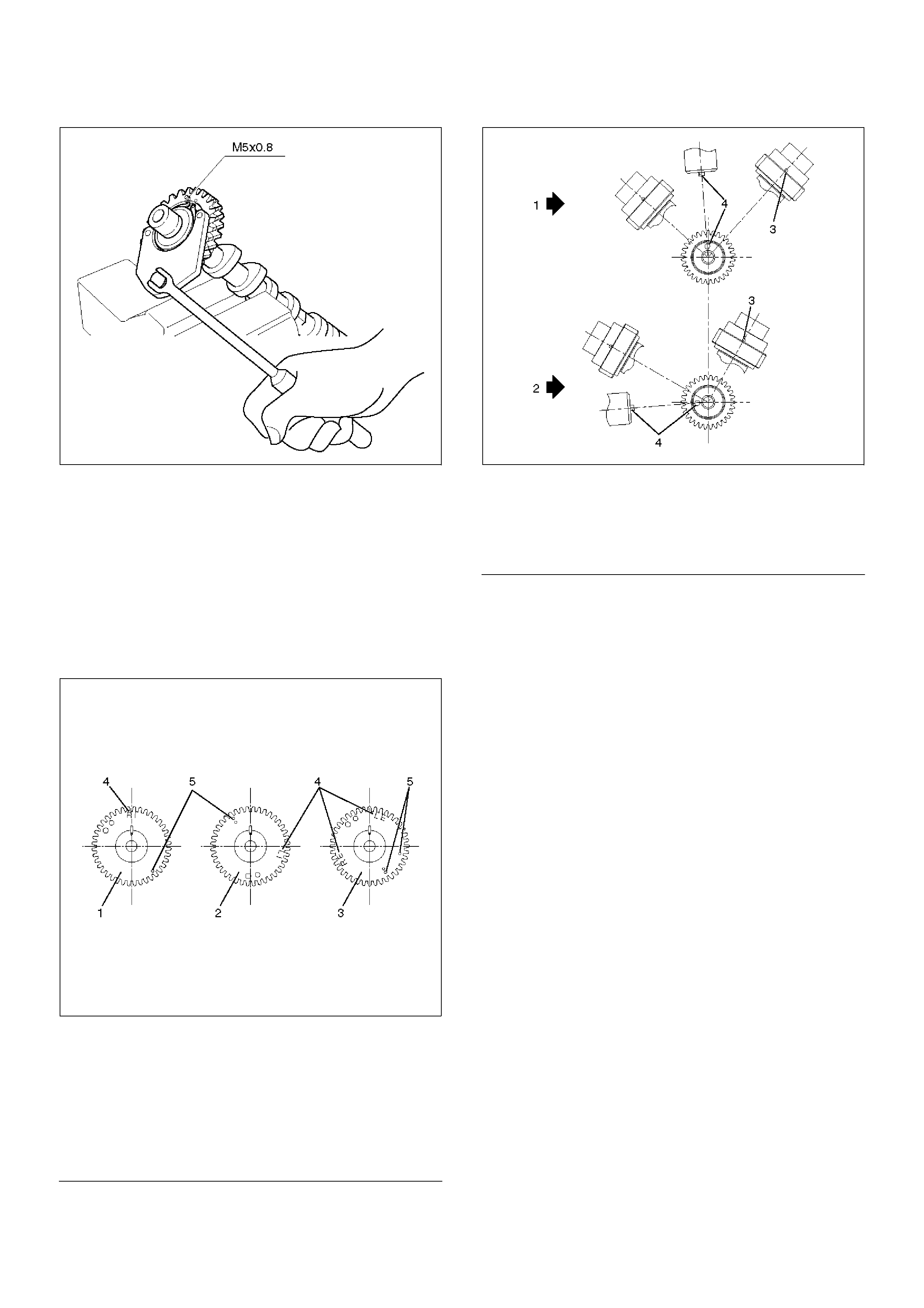
3. Tighten sub gear setting bolt.
1. Use the 5–8840–2443–0 gear spring lever to
turn sub gear to right direction until it aligns with
the M5 bolt hole between camshaft driven gear
and sub gear.
2. Tighten the M5 bolt to a suitable torque to
prevent the sub gear from moving.
Legend
(1) Right Bank
(2) Left Bank
(3) Timing Mark on Retainer
014RW041
4. Install camshaft assembly and camshaft brackets,
tighten twenty bolts on one side bank to the
specified torque.
1. Apply engine oil to camshaft journal and bearing
surface of camshaft bracket.
2. Align timing mark on intake camshaft (one dot
for right bank, two dot for left bank) and exhaust
camshaft (one dot for right bank, two dots for
left bank) to timing mark on camshaft drive gear
(one dot).
014RW020
EndOFC allout
014RW023
EndOFC allout
Legend
(1) Intake Camshaft Timing Gear for Right Bank
(2) Intake Camshaft Timing Gear for Left Bank
(3) Exhaust Camshaft Timing Gear
(4) Discrimination Mark
(LI: Left bank intake, RI: Right bank intake)
(LE: Left bank exhaust, RE: Right bank
exhaust)
Legend
(1) Right Bank Camshaft Drive Gear
(2) Left Bank Camshaft Drive Gear
(3) Timing Mark on Drive Gear
(4) Dowel Pin

014RW024
EndOFCallout
3.Tighten twenty bolts on numerical order an one
side bank as shown in the illustration.
Torque : 10 N·m (1.0 Kg·m/89 lb in)
014RW031
5.Install cylinder head cover RH.
•Refer to installation procedure for CYLINDER
HEAD COVER RH in this manual.
6.Install cylinder head cover LH.
•Refer to installation procedure for CYLINDER
HEAD COVER LH in this manual.
7.Install timing belt.
•Refer to installation procedure for TIMING BELT
in this manual.
8.Install crankshaft pulley.
•Refer to installation procedure for CRANKSHAFT
PULLEY in this manual.
Accelerator pedal cable adjustment
1. Loosen adjusting nut and lock nut.
2. Pull outer cable while closing fully the throttle
valve.
3. Tighten adjusting nut and lock nut temporarily.
Legend
(1) Right Bank
(2) Left Bank
(3) Alignment Mark on Camshaft Drive Gear
(4) Alignment Mark on Camshaft
(5) Alignment Mark on Retainer
4. Loosen adjusting nut by three turns and tighten
lock nut.
Then, manually operating the throttle valve,
make sure that the valve lever returns up to the
stopper screw.
If it does not reach the stopper screw, repeat
from step 1.
035RW004
EndOFC allout
Legend
(1) Clearance
(2) Lock Nut
(3) Adjusting Nut
Cylinder Head
Removal
1.Remove engine hood.
2.Disconnect battery ground cable.
3.Drain radiator coolant.
4.Drain engine oil.
5.Remove crankshaft pulley.
•Refer to removal procedure for Crankshaft Pulley
in this manual.
6. Remove timing belt.
•Refer to removal procedure for Timing Belt in this
manual.
7. Remove cylinder head cover LH.
•Refer to removal procedure for Cylinder Head
Cover LH in this manual.
8. Remove cylinder head cover RH.
•Refer to removal procedure for Cylinder Head
Cover RH in this manual.
9. Remove common chamber.
•Refer to removal procedure for Common
Chamber in this manual.
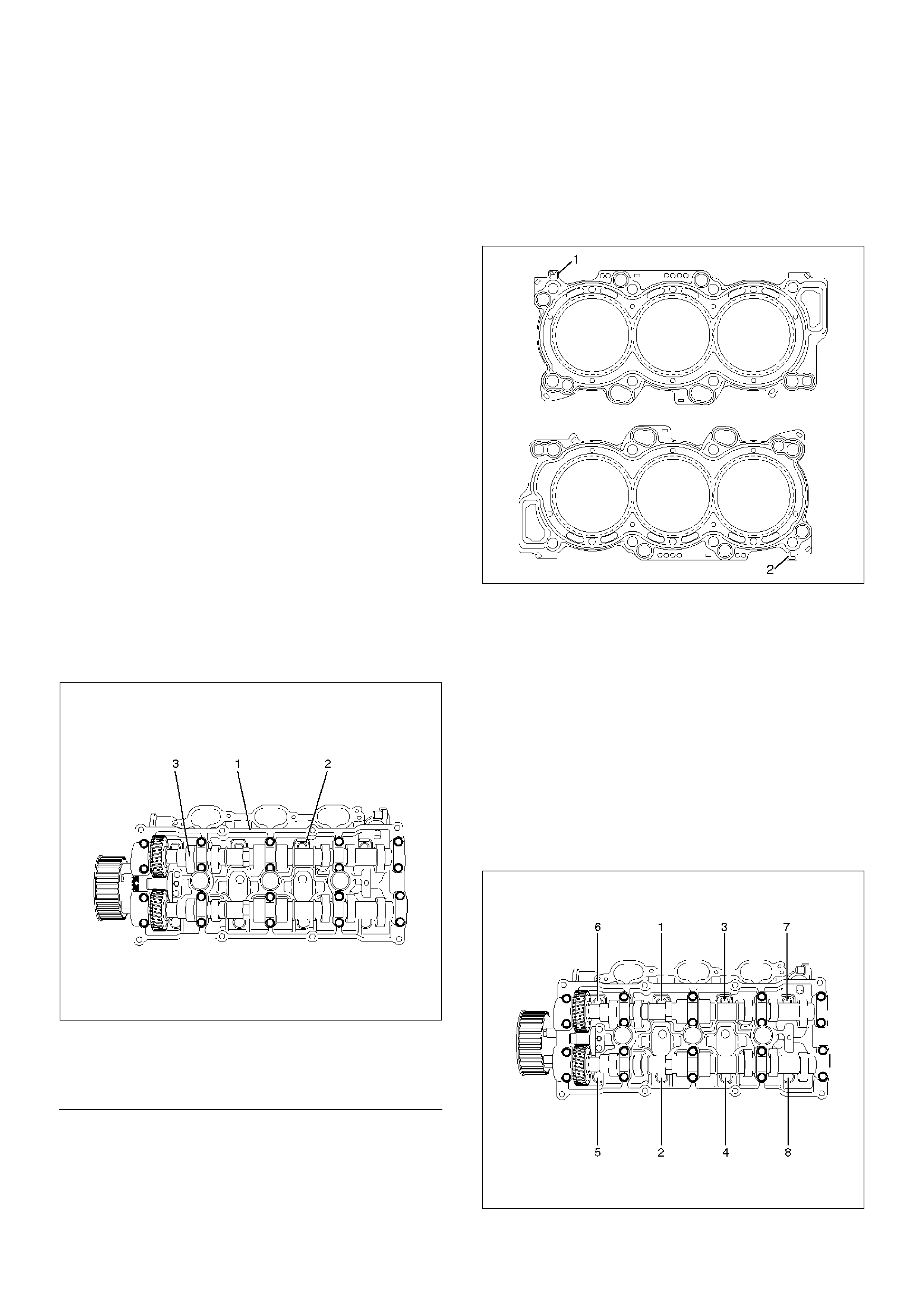
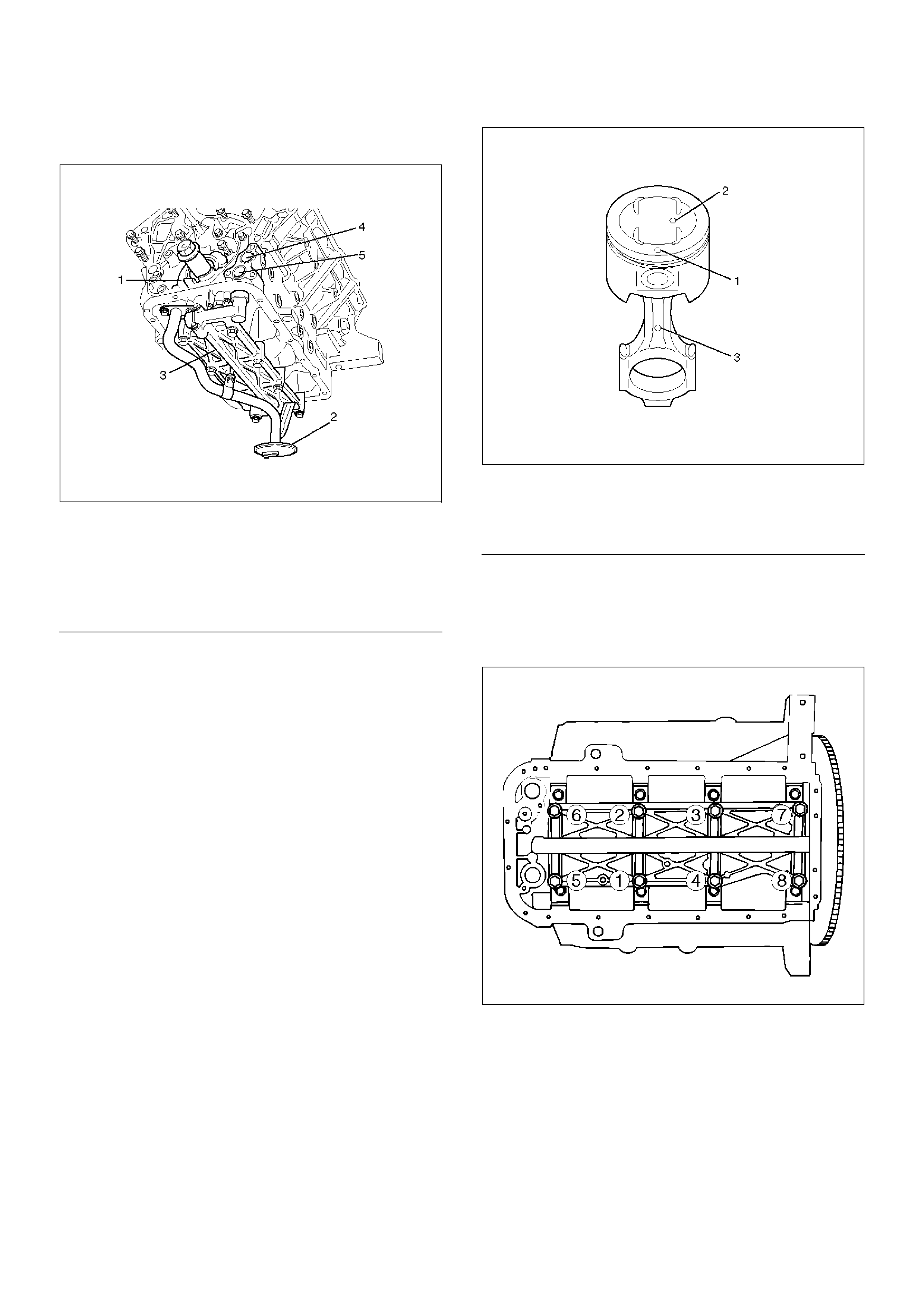
10. Remove cylinder head assembly.
1. Loosen eights bolts for tight cylinder head.
2. Remove cylinder head assembly.
014RW028
EndOFC allout
Installation
1. Install cylinder head assembly to cylinder block.
1. Put cylinder head gasket on the cylinder block.
NOTE: There is discrimination mark “R” for right bank
and “L” for left bank on the cylinder head gasket as
shown in the illustration.
Do not reuse cylinder head gasket.
011RW005
2. Align dowel pin hole to dowel pin on the cylinder
block.
3. Tighten two bolts temporarily by hand to prevent
the cylinder head assembly from moving.
4. Using 9–8511–4209–0 cylinder head bolt
wrench, tighten bolts in numerical order as
shown in the illustration to the specified torque.
NOTE: Do not reuse cylinder head bolts.
Do not apply any lubricant to the cylinder head bolts.
Torque :
Temporary : 29 N·m (3.0 Kg·m/21 lb ft)
Final : 64 N·m (6.5 Kg·m/47 lb ft)
014RW029
Legend
(1) Cylinder Head
(2) Cylinder Head Bolt
(3) Camshaft
2.Install common chamber.
•Refer to installation procedure for Common
Chamber in this manual.
3. Install cylinder head cover RH.
•Refer to installation procedure for Cylinder Head
Cover RH in this manual.
4. Install cylinder head cover LH.
•Refer to installation procedure for Cylinder Head
Cover LH in this manual.
5. Install timing belt.
•Refer to installation procedure for Timing Belt in
this manual.
6. Install crankshaft pulley.
•Refer to installation procedure for Crankshaft
Pulley in this manual.
Accelerator pedal cable adjustment
1. Loosen adjusting nut and lock nut.
2. Pull outer cable while closing fully the throttle
valve.
3. Tighten adjusting nut and lock nut temporarily.
4. Loosen adjusting nut by three turns and tighten
lock nut.
Then, manually operating the throttle valve,
make sure that the valve lever returns up to the
stopper screw.
If it does not reach the stopper screw, repeat
from step 1.
035RW004
EndOFC allout
Legend
(1) Clearance
(2) Lock Nut
(3) Adjusting Nut
Valve Stem Oil Controller , Valve Spring and Valve Guide
Removal
1.Disconnect battery ground cable.
2.Drain engine oil.
•Drain engine coolant.
3.Remove cylinder head assembly.
•Refer to removal procedure for Cylinder Head in
this manual.
4.Remove camshaft.
•Refer to removal procedure for Camshaft in this
manual.
5.Remove tappets with shim.
NOTE: Do not damage shim surface.
6.Remove valve springs using 5–8840–2446–0 valve
spring compressor and 5–8840–2547–0 valve
spring compressor adapter then remove upper
valve spring seat and lower seat.
014RW042
7.Remove oil controller using 5–8840–0623–0 oil
controller remover, remove each valve stem oil
controller.
8.Remove valve guide using 5–8840–2549–0 valve
guide replacer.
Installation
1.Install valve guide using 5–8840–2442–0 valve
guide installer.
2.Install oil controller using 5–8840–0624–0 oil
controller installer.
3.Install lower valve spring seat, valve spring and
upper valve spring seat then put split collars on the
upper spring seat, using 5–8840–2446–0 valve
spring compressor and 5–8840–2547–0 valve
spring compressor adapter to install the split collars.
014RW042
4.Install tappet with shim.
5. Install camshaft assembly.
•Refer to installation procedure for Camshaft in
this manual.
6. Install cylinder head assembly.
•Refer to installation procedure for Cylinder Head
in this manual.
7. Fill engine oil until full level.
8. Fill engine coolant.
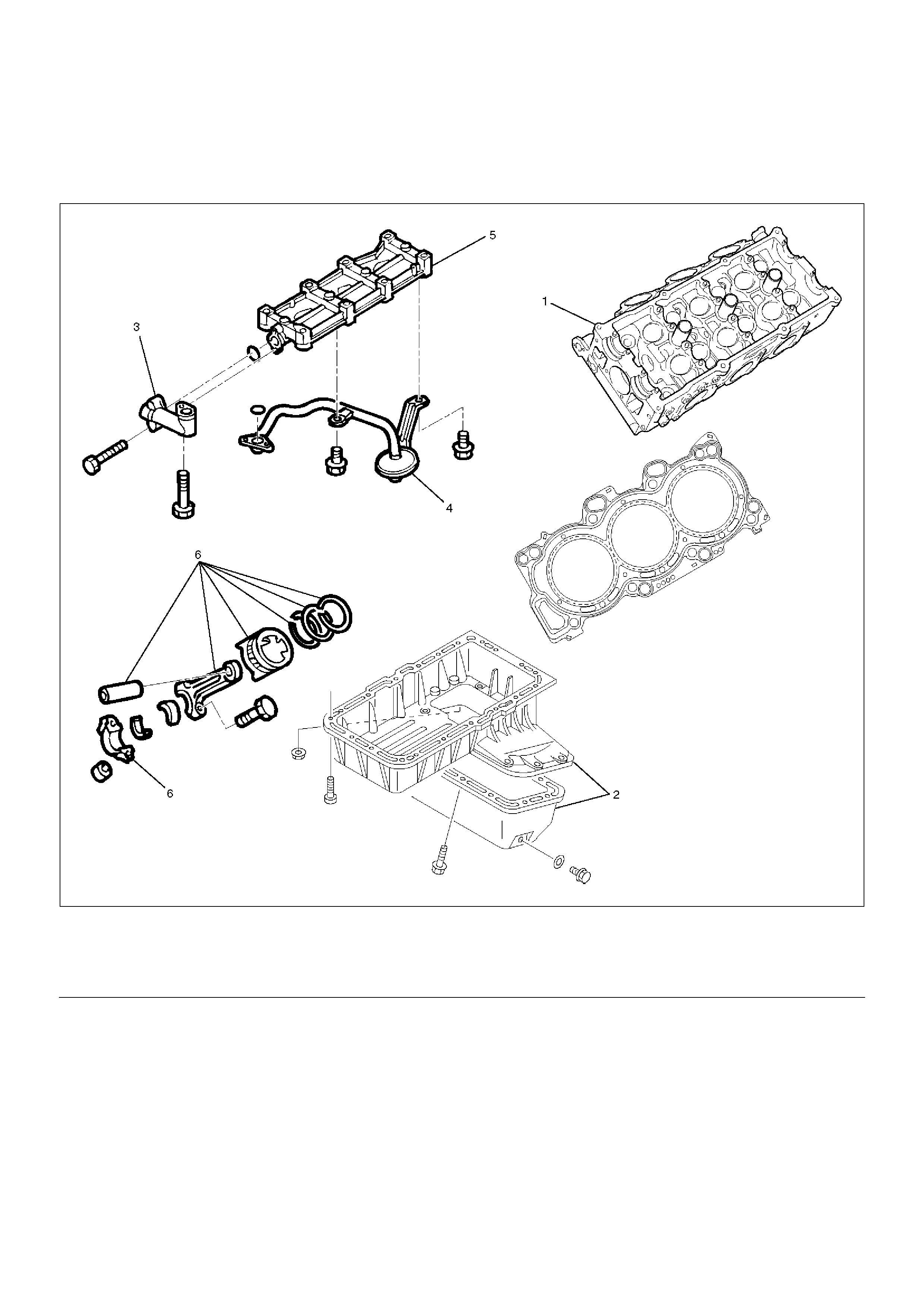
Piston, Piston Ring and Connecting Rod
Removal
F06RW011
EndOFCallout
1.Remove cylinder head assembly.
•Refer to removal procedure for Cylinder Head in
this manual.
2. Remove crankcase with Oil Pan.
•Refer to removal procedure for Oil Pan and
Crankcase in this manual.
Legend
(1) Cylinder Head
(2) Crankcase with Oil Pan
(3) Oil Pipe
(4) Oil Strainer
(5) Oil Gallery
(6) Piston with Connecting Rod Assembly
3.Remove oil strainer fixing bolts, remove oil strainer
assembly with O-ring.
050RW002
EndOFCallout
4.Remove three fixing bolts, oil pipe with O-ring.
5.Remove eight fixing bolts, oil gallery.
6.Remove piston with connecting rod assembly,
before removing the bearing cap, remove carbon on
the top of cylinder bore and push piston with
connecting rod out from the top of cylinder bore.
Installation
1.Install piston with connecting rod assembly.
•Apply engine oil to cylinder bore, connecting rod
bearing and crank pin.
When installing the piston, its front mark must
face the engine front side.
•The bearing cap number must be the same as
connecting rod number.
•Apply engine oil to the thread and seating surface
of each nut.
•Tighten nuts to the specified torque.
Torque : 54 N·m (5.5 Kg·m/40 lb ft)
•After tightening the nuts, make sure that the
crankshaft rotates smoothly.
NOTE: Do not apply engine oil to the bearing back
faces and connecting rod bearing fitting surfaces.
015RW003
EndOFCallout
2.Install oil gallery and tighten the bolts in two steps, in
the order shown in illustration.
Torque :
1st step : 29 N·m (3.0 Kg·m/21 lb ft)
2nd step : 55°–65°
051RS009
3.Install oil pipe with O-ring.
Torque : 10 N·m (1.0 Kg·m/89 lb in)
4.Install oil strainer assembly with O-ring.
Torque : 25 N·m (2.5 Kg·m/18 lb ft)
5.Install crankcase with Oil Pan.
•Refer to installation procedure for Oil Pan and
Crankcase in this manual.
6. Install cylinder head assembly.
•Refer to installation procedure for Cylinder Head
in this manual.
Legend
(1) Oil Pump
(2) Oil Strainer
(3) Oil Gallery
(4) From Oil Filter
(5) To Oil Filter
Legend
(1) Piston Front Mark
(2) Piston Grade
(3) Connecting Rod Front Mark
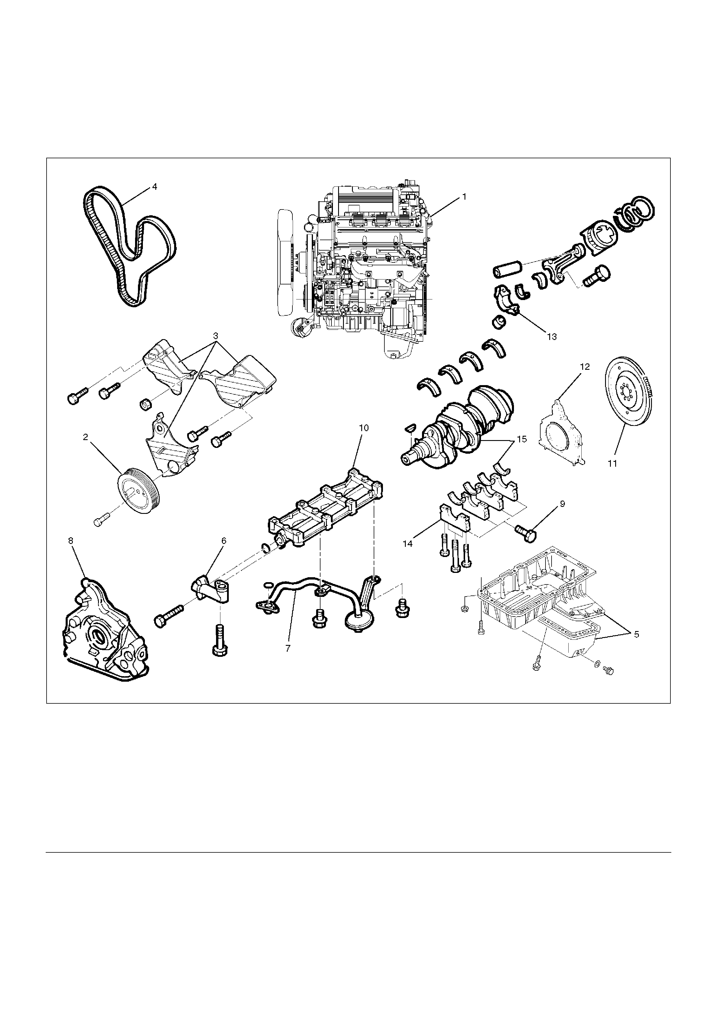
Crankshaft and Main Bearings
Removal
F06RW010
EndOFCallout
1.Remove engine assembly.
•Refer to removal procedure for Engine Assembly
in this manual.
2. Remove timing belt.
•Refer to removal procedure for Timing Belt in this
manual.
3. Remove oil pan and crankcase.
•Refer to removal procedure for Oil Pan and
Crankcase in this manual.
4.Remove oil pipe with O-ring.
5. Remove oil strainer assembly with O-ring.
Legend
(1) Engine Assembly
(2) Crankshaft Pulley
(3) Timing Belt Cover
(4) Timing Belt
(5) Crankcase with Oil Pan
(6) Oil Pipe
(7) Oil Strainer
(8) Oil Pump Assembly
(9) Cylinder Body Side Bolt
(10) Oil Gallery
(11) Flywheel
(12) Rear Oil Seal Retainer
(13) Connecting Rod Cap
(14) Crankshaft Main Bearing Cap
(15) Crankshaft and Main Bearing
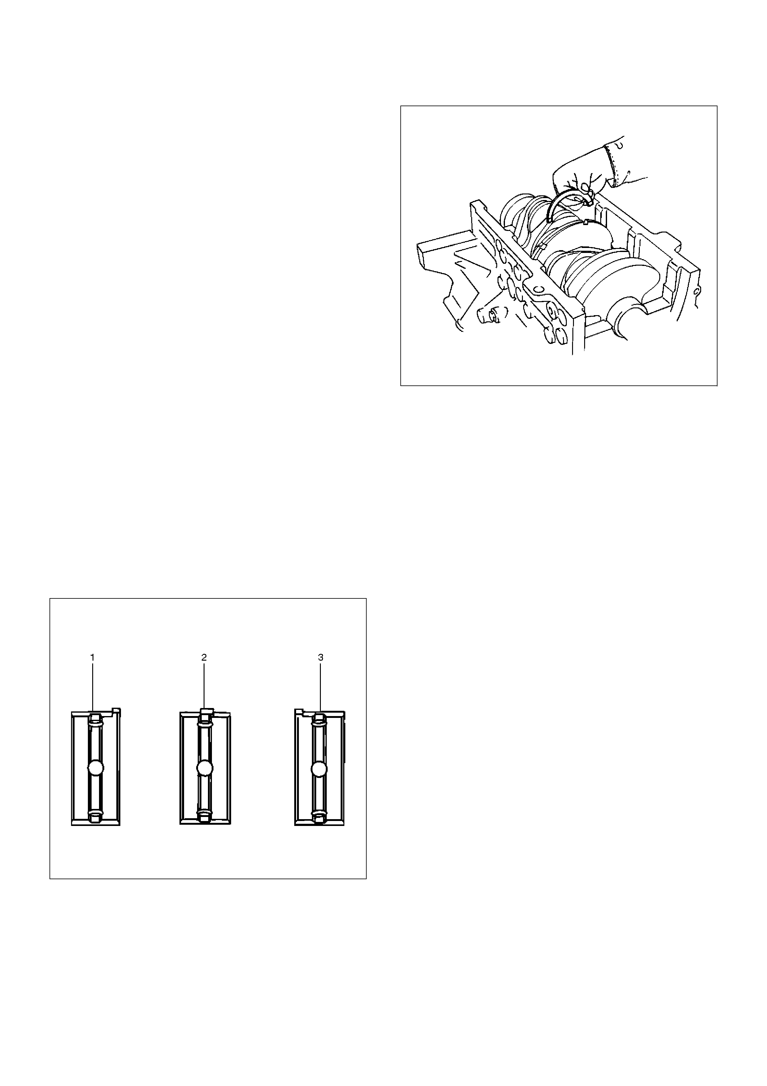
6.Remove oil pump assembly.
•Refer to removal procedure for Oil Pump in this
manual.
7. Remove cylinder body side bolts.
8. Remove oil gallery.
9. Remove flywheel.
10. Remove rear oil seal retainer.
•Refer to removal procedure for Rear Oil Seal in
this manual.
11. Remove connecting rod caps.
12. Remove crankshaft main bearing caps.
13. Remove crankshaft and main bearings.
Installation
1. Install crankshaft and main bearings.
• Install main bearing in the cylinder block and
main bearing cap respectively.
Apply new engine oil to upper and lower main
bearings.
NOTE:
• Do not apply engine oil to the bearing back faces.
• Make sure that main bearings are in correct position.
• Install crankshaft with care.
• Apply engine oil to the thrust washer.
• Install thrust washer on No.3 journal.
• Oil grooves in thrust washer must face the
crankshaft.
015RS012
015RS013
2. Install crankshaft main bearing caps.
• Apply engine oil to the thread and seating surface
of each bearing cap fixing bolt.
NOTE:
• Do not apply engine oil to the bearing back faces.
• Install bearing caps in the order of numbers, starting
with cylinder block front side.
• Tighten main bearing fixing bolts to the specified
torque.
Torque : 39 N·m (4.0 Kg·m/29 lb ft)
• After tightening the bolts, make sure that the
crankshaft rotates smoothly.
3. Install connecting rod caps.
• The cap number must be same as connecting rod
number.
• Apply engine oil to the thread and seating surface
of each nut.
• Tighten nuts to the specified torque.
Torque : 54 N·m (5.5 Kg·m/40 lb ft)
• After tightening the nuts, make sure that the
crankshaft rotates smoothly.
4. Install rear oil seal retainer.
• Remove oil on cylinder block and retainer fitting
surface.
• Apply sealant (TB1207B or equivalent) to retainer
fitting surface as shown in illustration.
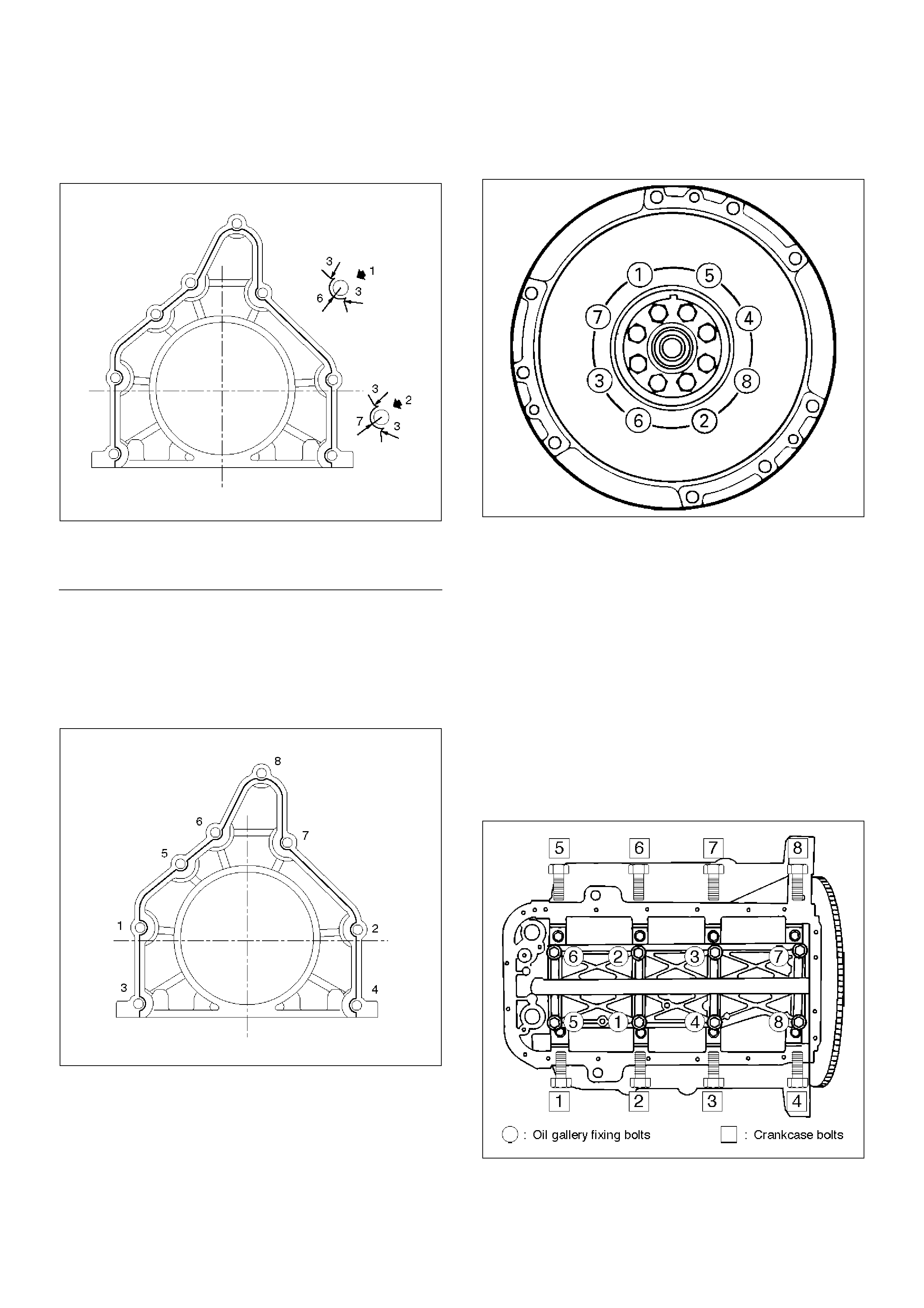
• The oil seal retainer must be installed within 5
minutes after sealant application before the
sealant hardens.
015RW002
EndOFC allout
• Apply engine oil to oil seal lip and align a dowel
pin hole in the cylinder block with that in the
retainer.
• Tighten retainer fixing bolts to the specified
torque.
Torque : 18 N·m (1.8 Kg·m/13 lb ft)
015RW001
5. Install flywheel.
• Clean tapped holes in the crankshaft.
• Remove oil on crankshaft and flywheel fitting
surface.
NOTE:
• Do not reuse the bolts.
• Do not apply oil or thread lock to the bolts.
• Tighten fixing bolts to the specified torque.
Torque : 54 N·m (5.5 Kg·m/40 lb ft)
015RS018
6. Install oil gallery.
• Clean contact surface of oil gallery and main
bearing cap.
Apply engine oil to oil gallery fixing bolts and
tighten the bolts in two steps, in the order shown
in illustration.
Torque :
1st step : 29 N·m (3.0 Kg·m/21 lb ft)
2nd step : 55°–65°
7. Install cylinder body side bolts and tighten bolts in
order to the specified torque.
Torque : 39 N·m (4.0 Kg·m/29 lb ft)
NOTE: Do not apply the oil to the bolts.
012RS007
8. Install oil pump assembly.
• Remove oil on cylinder block and oil pump
mounting surface.
Legend
(1) Around Bolt Holes
(2) Around Dowel Pin
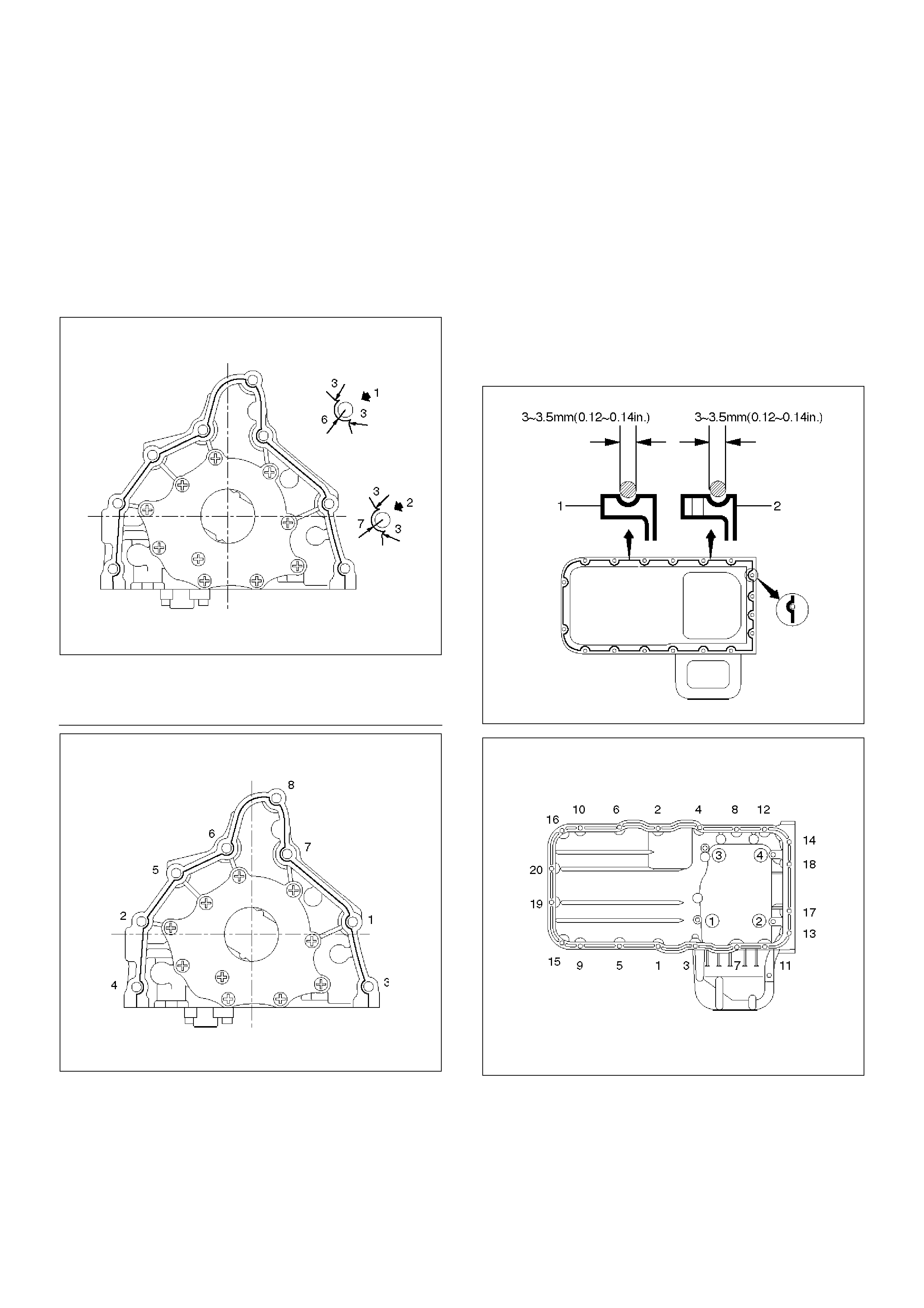
• Apply sealant (TB1207B or equivalent) to the oil
pump mounting surface.
• The oil pump assembly must be installed within 5
minutes after sealant application before the
sealant hardens.
• Apply engine oil to oil seal lip.
• Install oil pump in the cylinder block and tighten
fixing bolts to the specified torque.
Torque : 25 N·m (2.5 Kg·m/18 lb ft)
051RW002
EndOFC allout
051RW001
9. Install oil strainer with O-ring, tighten to the specified
torque.
Torque : 25 N·m (2.5 Kg·m/18 lb ft)
10. Install oil pipe with O-ring, tighten fixing bolts to the
specified torque.
Torque : 25 N·m (2.5 Kg·m/18 lb ft)
11. Install crankcase.
• Remove oil on crankcase mounting surface and
dry the surface.
• Properly apply a 4.5 mm (0.7 in) wide bead of
sealant (TB1207C or equivalent) to the
crankcase mounting surface. The bead must be
continuous.
• The crankcase must be installed within 5 minutes
after sealant application before the sealant
hardens.
• Tighten fixing bolts to the specified torque.
Torque : 10 N·m (1.0 Kg·m/89 lb in)
013RW010
013RW004
12. Install oil pan
• Remove oil on oil pan mounting surface and dry
the surface.
• Properly apply a 4.5 mm (0.7 in) wide bead of
sealant (TB1207C or equivalent) to the oil pan
mounting surface. The bead must be continuous.
Legend
(1) Around Bolt Holes
(2) Around Dowel Pin
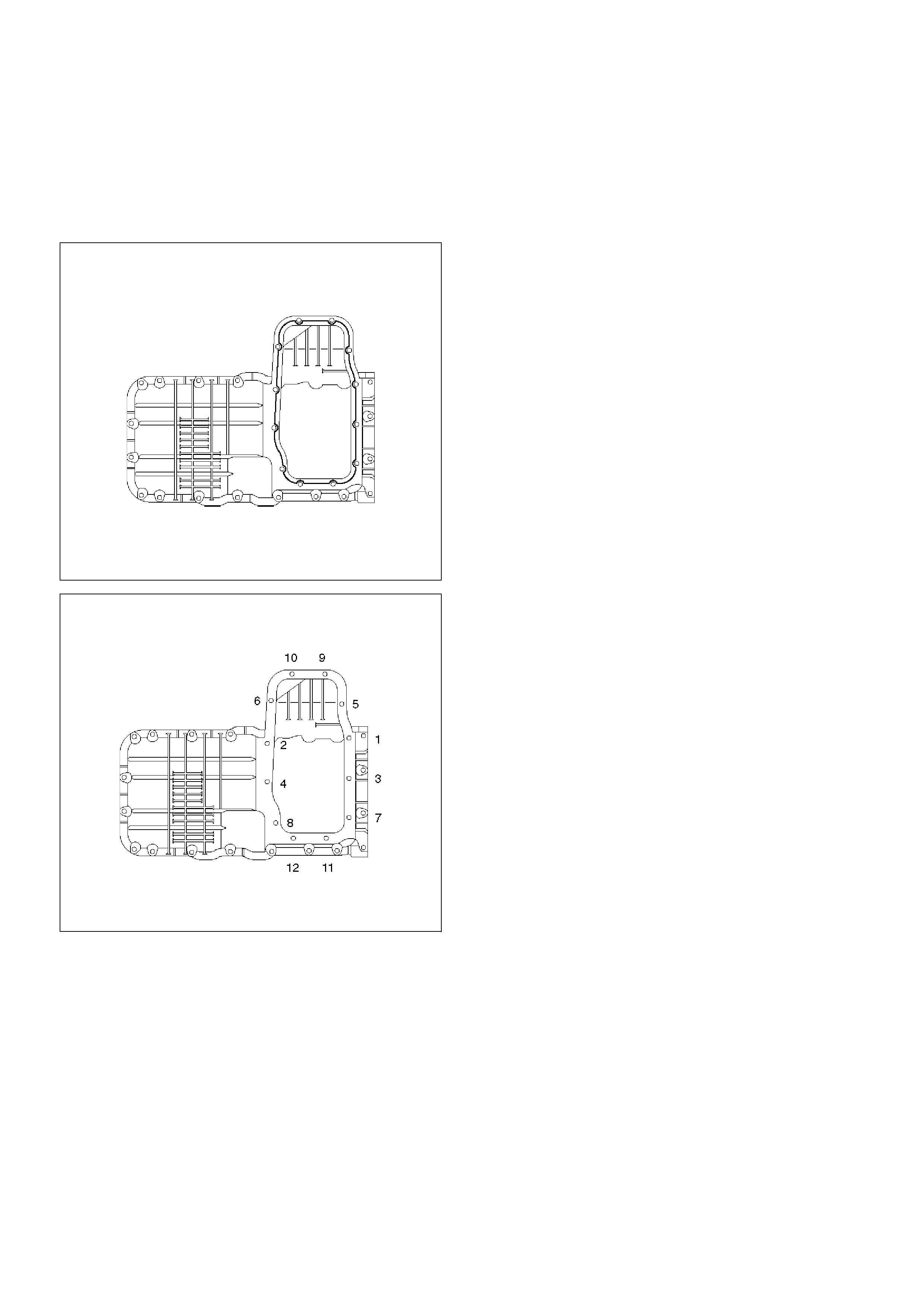
•The oil pan must be installed within 5 minutes
after sealant application to prevent premature
hardening of sealant.
•Tighten fixing bolts to the specified torque.
Torque : 25 N·m (2.5 Kg·m/18 lb ft)
013RW003
013RW002
13.Install timing belt.
•Refer to installation procedure for Timing Belt in
this manual.
14. Install engine assembly.
•Refer to installation procedure for Engine in this
manual.
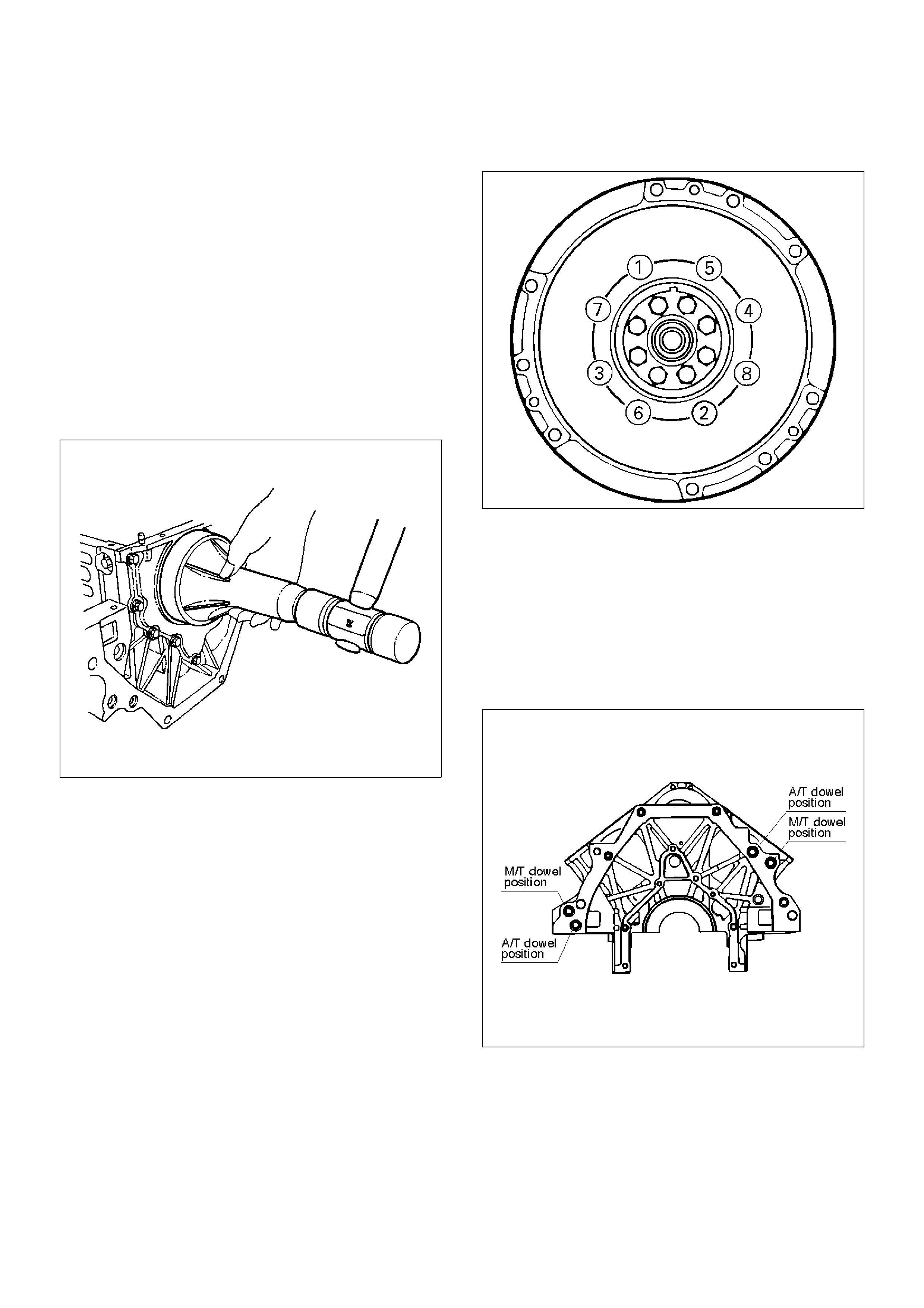
Rear Oil Seal
Removal
1.Remove transmission assembly.
•Refer to removal procedure for Section 7B
or Section 7D in this manual.
2.Remove flywheel.
3.Remove rear oil seal using a seal remover.
NOTE: Take care not to damage the crankshaft or oil
seal retainer when removing oil seal.
Installation
1.Apply engine oil to oil seal lip and install oil seal
using 5–8840–2286–0.
015RS017
2.Install flywheel.
•Clean tapped holes in the crankshaft.
•Remove oil on the crankshaft and flywheel
mounting surface.
•Tighten fixing bolts to the specified torque.
NOTE: Do not reuse the bolts and do not apply oil or
thread lock to the bolts.
Torque : 54 N·m (5.5 Kg·m/40 lb ft)
015RS018
3.Install transmission.
•See Transmission section in this manual.
CAUTION: When assembling the engine and
transmission, confirm that dowels have been
mounted in the specified positions at the engine
side. Take care that dowel positions are different
between the manual transmission and the
automatic transmission.
Otherwise, the transmission may be damaged.
012RS009
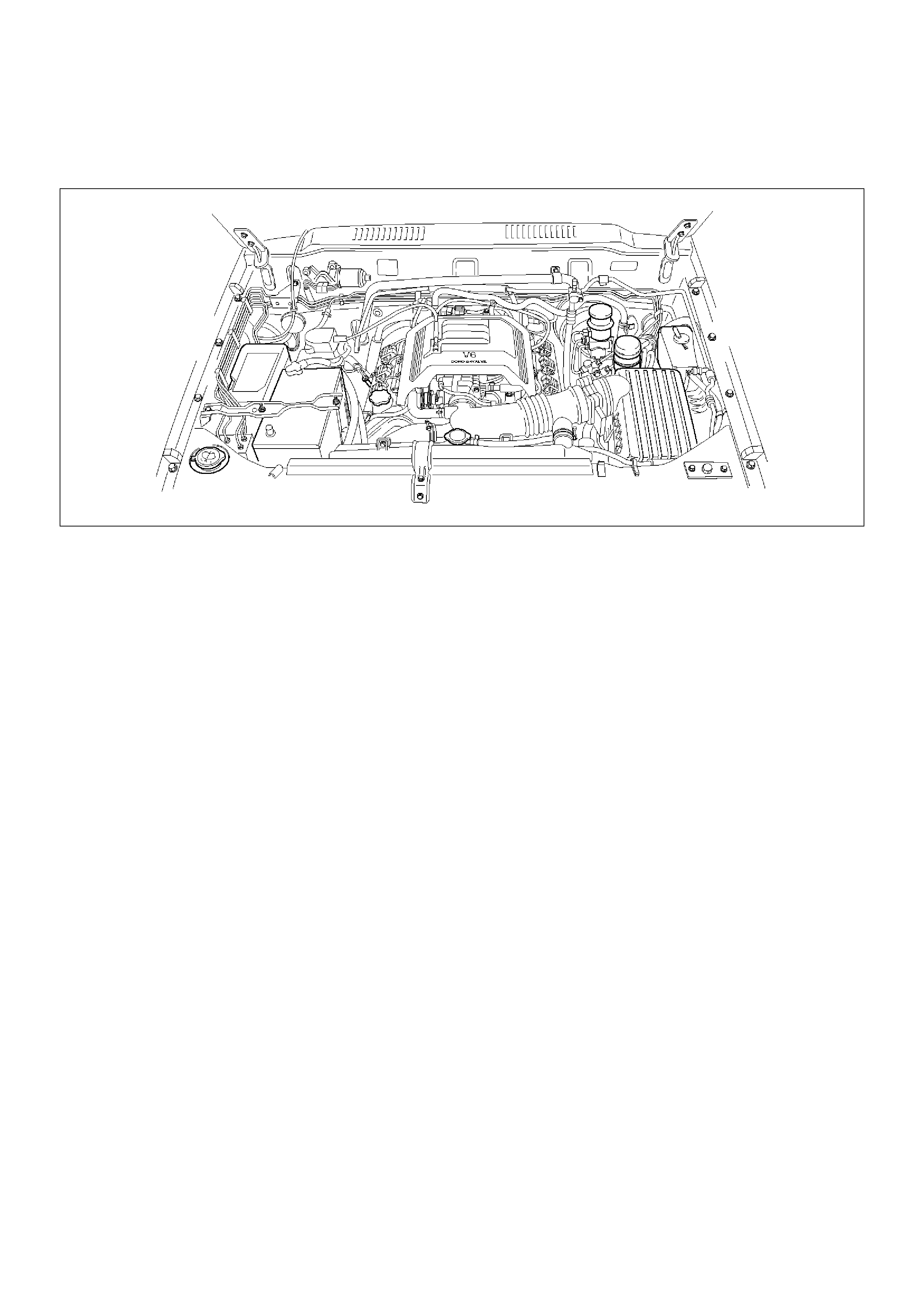
Engine Assembly
Removal
035RW027
1.Disconnect battery ground and positive cable.
2.Remove battery.
3.Make alignment mark on the engine hood and
hinges before removal in order to return the hood to
original position exactly.
4.Remove engine hood.
5.Drain radiator coolant.
6.Disconnect accelerator cable and automatic cruise
control cable from throttle valve on common
chamber.
7.Disconnect air duct with air cleaner cover.
8.Remove air cleaner assembly.
9.Disconnect canister vacuum hose.
10.Disconnect vacuum booster hose.
11.Disconnect three engine harness connectors.
12.Disconnect harness connector to transmission (left
front side of engine compartment), disconnect shift
on the fly harness connector from front side of front
axle and remove transmission harness bracket from
engine left side.
13.Disconnect ground cable between engine and
frame.
14.Disconnect bonding cable connector on the back of
right dash panel.
15.Disconnect bonding cable terminal on the left bank.
16.Disconnect starter harness connector from starter.
17.Disconnect generator harness connector from
generator.
18.Disconnect coolant reserve tank hose from radiator.
19.Remove radiator upper and lower hoses.
20.Remove upper fan shroud.
21.Remove cooling fan assembly four fixing nuts, then
the cooling fan assembly.
22.Move drive belt tensioner to loose side using
wrench then remove drive belt.
23.Remove power steering pump fixing bolts, then
power steering pump. Place the power steering
pump along with piping on the body side.
24.Remove air conditioning compressor fixing bolts
from bracket and place the compressor along with
piping on the body side.
25.Remove O2 sensor harness connectors from
exhaust front pipe.
26.Remove three exhaust pipe fixing nuts from each
bank.
27.Remove two exhaust pipe fixing nuts from each
exhaust pipe, then move exhaust pipe to rear side
of vehicle.
28.Remove flywheel dust covers.
29.Disconnect two heater hoses from engine.
30.Disconnect fuel hoses from right side of
transmission.
CAUTION: Plug fuel pipes on engine side and fuel
hoses from fuel tank.
31.Remove transmission assembly. Refer to
section 7B or section 7D in this manual.
32. Support the engine by engine hoist.
33. Remove two left side engine mount fixing bolts from
engine mount on chassis side.
34. Remove two right side engine mount fixing bolts
from engine mount on chassis side.
35. Remove engine assembly.
Installation
CAUTION: When assembling the engine and
transmission, confirm that dowels have been
mounted in the specified positions at the engine
side. Take care that dowel positions are different
between the manual transmission and the
automatic transmission.
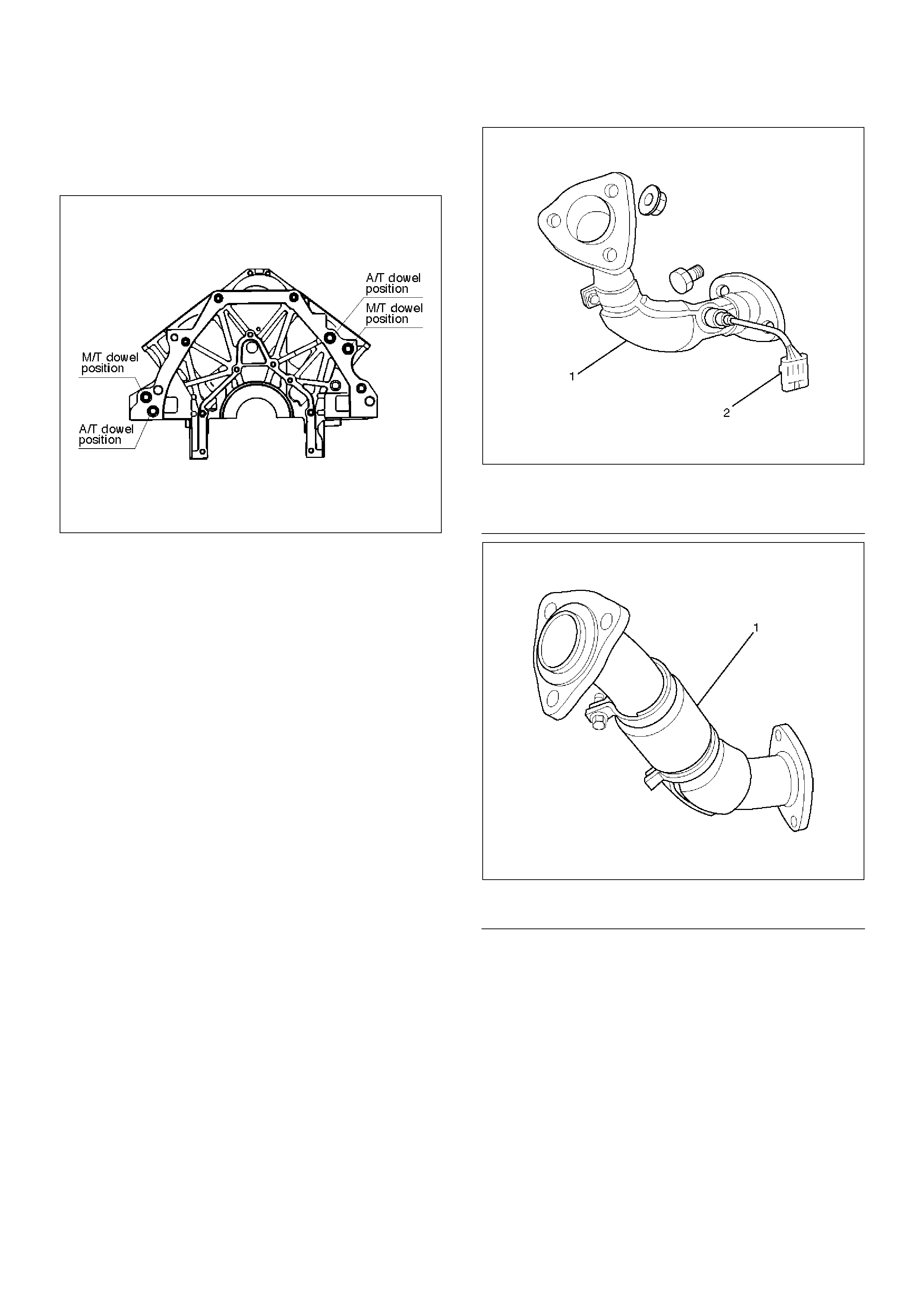
If the engine is assembled in the condition that the
dowels have not been mounted in the specified
positions, the transmission may be damaged the
transmission.
012RS009
1.Install engine assembly. Tighten engine mount fixing
bolts to frame to the specified torque.
Torque: 41 N·m (4.2 Kg·m/30 lb ft)
2.Reconnect fuel hose to fuel pipe on engine.
3.Install transmission assembly. Refer to
section 7C or section 7D in this manual.
4. Reconnect two heater hoses to engine.
5. Install flywheel dust covers.
6. Install exhaust pipe and temporally tighten two
(each bank) rear exhaust flange nuts then tighten
three stud nuts (each bank) between exhaust
manifold and exhaust pipe, finally tighten rear side
nuts to the specified torque.
Torque:
Nuts: 43 N·m (4.4 Kg·m/32 lb ft)
Stud nuts: 67 N·m (6.8 Kg·m/49 lb ft)
150RW061
EndOFC allout
150RW062
EndOFC allout
7. Reconnect O2 sensor connector.
8. Install cooling fan assembly and tighten bolts/nuts to
the specified torque.
Torque : 22 N·m (2.2 Kg·m/16 lb ft) for fan pulley
and fan bracket.
Torque : 10 N·m (1.0 Kg·m/88.5 lb in) for fan and
clutch assembly.
Legend
(1) Exhaust Front Pipe RH
(2) O2 Sensor (for IGM)
Legend
(1) Exhaust Front Pipe LH
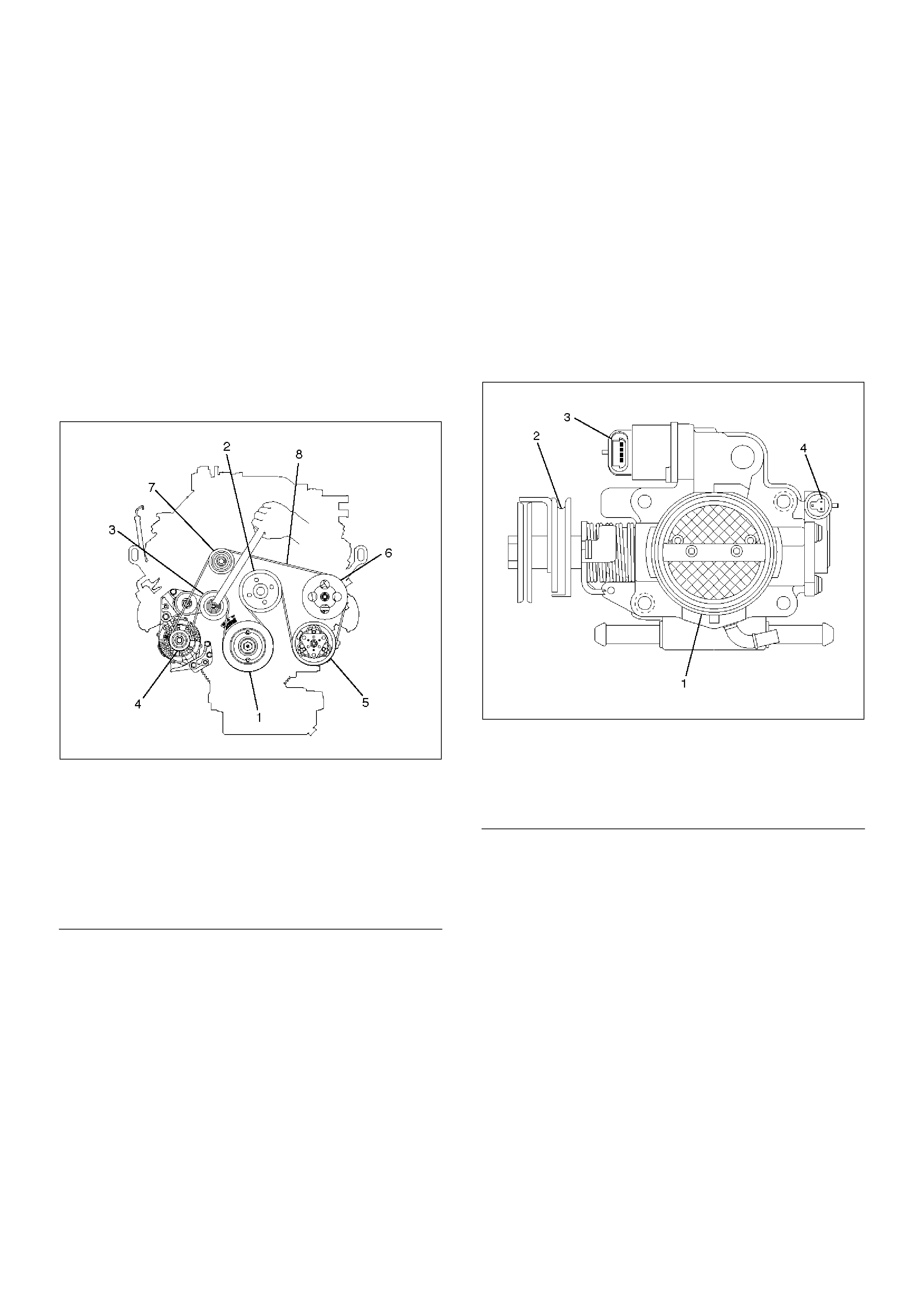
9. Install air conditioner compressor to engine and
tighten to the specified torque.
Torque :
M8 bolts : 22 N·m (2.2 Kg·m/16 lb ft)
M10 bolts : 43 N·m (4.4 Kg·m/32 lb ft)
10. Install power steering pump, tighten fixing bolt to the
specified torque.
Torque :
M8 bolts : 22N·m (2.2 Kg·m/16 lb ft)
M10 bolts : 46 N·m (4.7 Kg·m/34 lb ft)
11. Move drive belt tensioner to loose side using
wrench, then install drive belt to normal position.
850RW001
EndOFC allout
12. Install upper fan shroud.
13. Reconnect radiator upper and lower hoses.
14. Reconnect coolant reserve tank hose to radiator.
15. Reconnect generator harness connector.
16. Reconnect starter harness connector.
17. Reconnect bonding cable terminal on left bank
18. Reconnect bonding cable terminal on the back of
right dash panel.
19. Reconnect ground cable between engine and
chassis.
20. Reconnect harness connector to transmission and
install transmission harness bracket on engine left
side.
21. Reconnect three engine harness connectors.
22. Reconnect vacuum booster hose.
23. Reconnect canister vacuum hose.
24. Install air cleaner assembly.
25. Reconnect air duct.
26. Reconnect accelerator cable and automatic cruise
control cable to throttle valve on common chamber.
035RW007
EndOFC allout
27. Install engine hood to the original position.
•Refer to Body section.
Accelerator pedal cable adjustment
1. Loosen adjusting nut and lock nut.
2. Pull outer cable while fully closing the throttle
valve.
3. Tighten adjusting nut and lock nut temporarily.
4. Loosen adjusting nut by three turns and tighten
lock nut.
Then, manually operating the throttle valve,
make sure that the valve lever returns up to the
stopper screw.
If it does not reach the stopper screw, repeat
from step 1.
Legend
(1) Crankshaft Pulley
(2) Cooling Fan Pulley
(3) Tensioner
(4) Generator
(5) Air Conditioner Compressor
(6) Power Steering Oil Pump
(7) Drive Belt
Legend
(1) Throttle Valve Assembly
(2) Throttle Lever
(3) Idle Air Control Valve
(4) Throttle Position Sensor
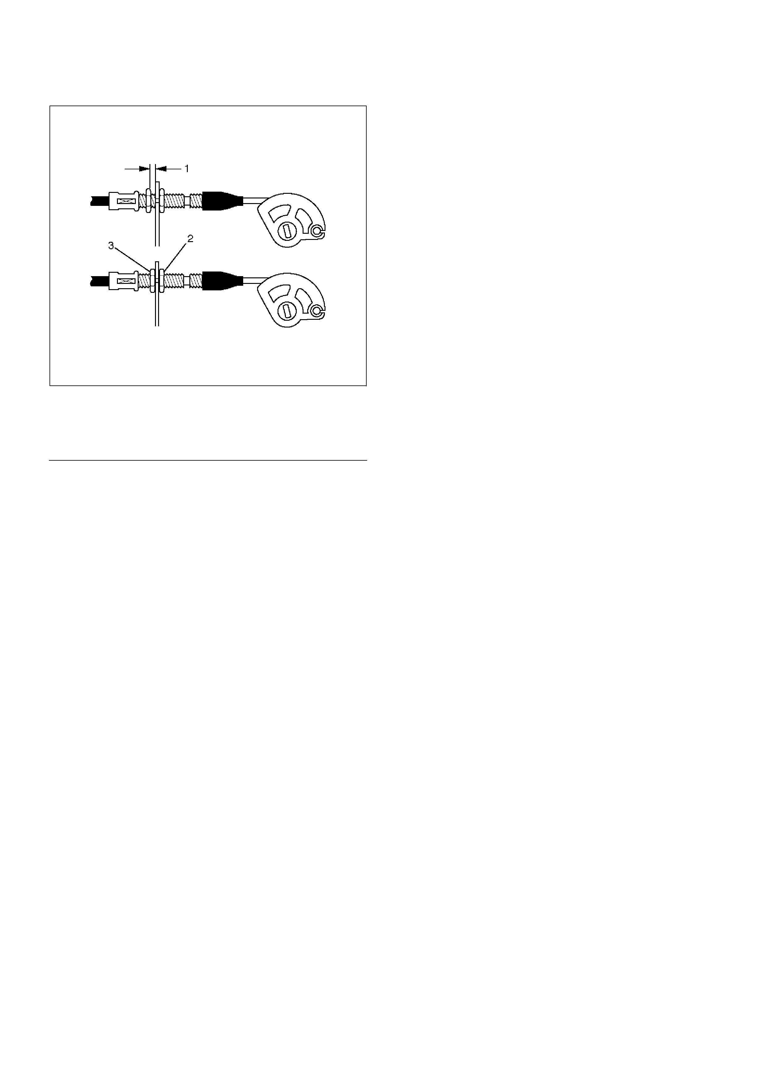
130RW004
EndOFC allout
Legend
(1) Clearance
(2) Lock Nut
(3) Adjusting Nut
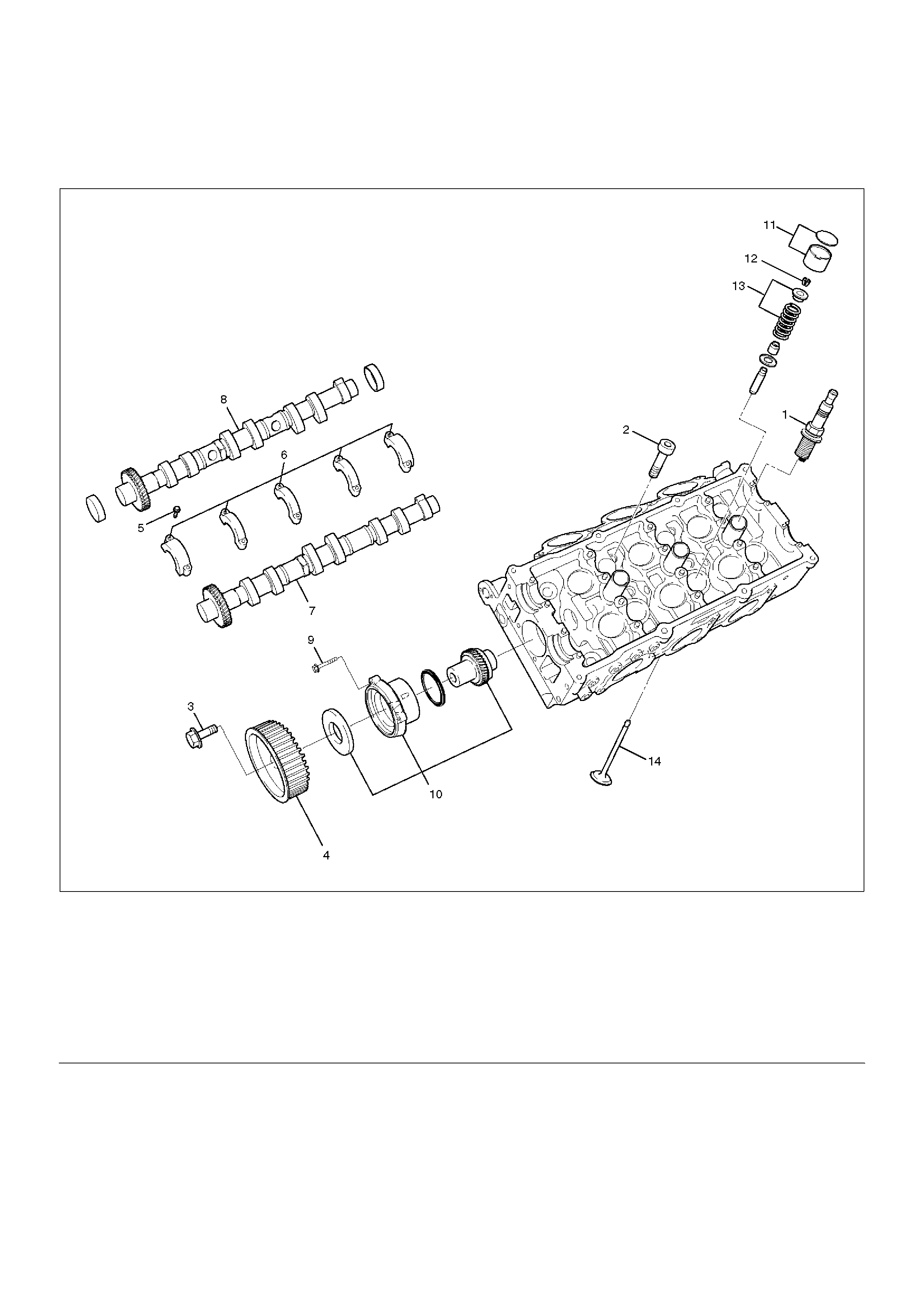
Cylinder Head
Cylinder Head and Associated Parts
011RW008
EndOFCallout
Disassembly
NOTE:
• During disassembly, be sure that the valve train
components are kept together and identified so that
they can be reinstalled in their original locations.
• Before removing the cylinder head from the engine
and before disassembling the valve mechanism,
perform a compression test and note the results.
1. Remove camshaft drive gear pulley fixing bolt (3),
then pulley (4).
Legend
(1) Spark Plug
(2) Cylinder Head Bolt
(3) Camshaft Drive Gear Pulley Fixing Bolt
(4) Camshaft Drive Gear Pulley
(5) Camshaft Bracket Fixing Bolt
(6) Camshaft Bracket
(7) Camshaft Exhaust
(8) Camshaft Intake
(9) Retainer Fixing Bolt
(10) Retainer Assembly
(11) Tappet with Shim
(12) Split Collar
(13) Valve Spring and Spring Upper Seat
(14) Valve
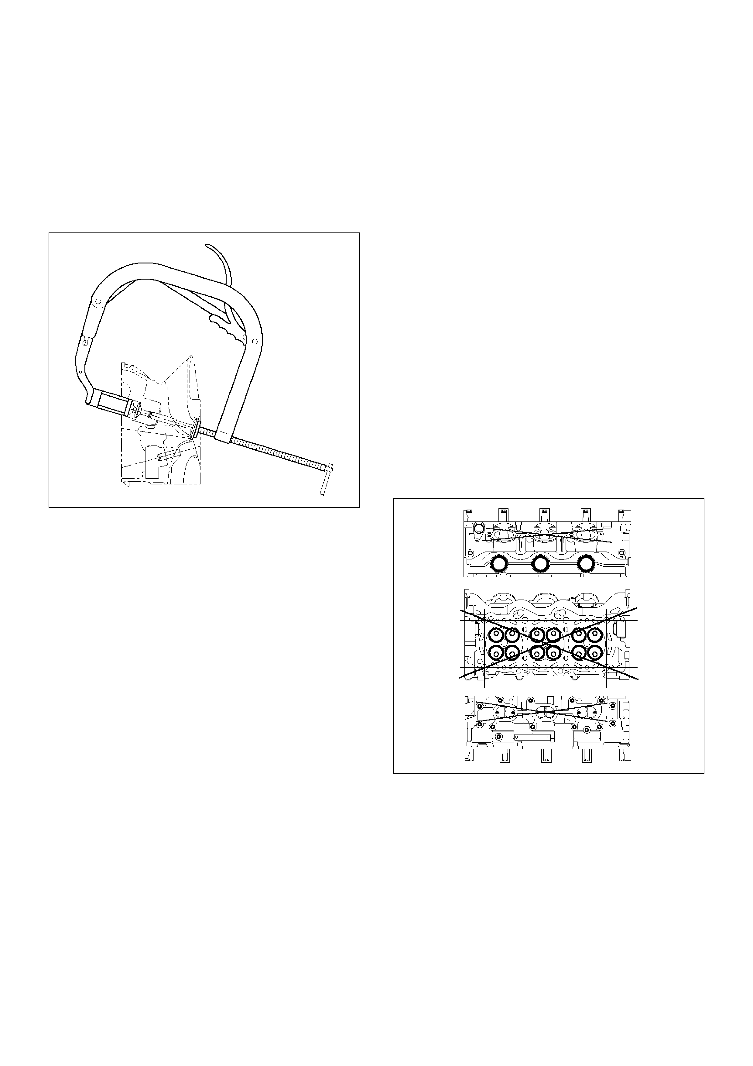
2.Remove camshaft bracket fixing bolt (5), camshaft
bracket (6), then camshaft exhaust (7), and intake
side (8).
3.Remove tappet with shim (11).
4.Use the 5–8840–2446–0 valve spring compressor
and 5–8840–2547–0 valve spring compressor
adapter to remove the split collar (12), valve spring
with upper seat (13) and valve (14).
014RW042
5.Remove spark plug (1).
CAUTION: Do not remove the spark plugs when the
head and plugs are hot. Clean dirt and debris from
spark plug recess areas before removal.
Clean
Cylinder head
Carefully remove all varnish, soot and carbon from the
bare metal. Do not use a motorized wire brush on any
gasket sealing surface.
Inspection and Repair
1.Cylinder head gasket and mating surfaces for leaks,
corrosion and blow–by. If the gasket has failed,
determine the cause.
–Insufficient torque on head bolts.
–Improper installation
–Loose or warped cylinder head
–Missing dowel pins
–Warped case surface
2.Cylinder head for cracks, especially between valve
seats and in the exhaust ports.
3.Cylinder head deck for corrosion, sand particles in
head and porosity.
CAUTION:
• Do not attempt to weld the cylinder head. Replace
it.
• Do not reuse cylinder head bolts.
4. Cylinder head deck, common chamber and exhaust
manifold mating surfaces for flatness. These
surfaces may be reconditioned by milling. If the
surfaces are “out of flat” by more than specification,
the surface should be ground to within
specifications. Replace the head if it requires
machining beyond the repairable limit.
Head surface and manifold surface
Standard: 0.05 mm (0.002 in) or less
Warpage limit: 0.2 mm (0.0079 in)
Maximum Repairable limit: 0.2 mm (0.0079 in)
Head height
Standard height : 133.2 mm (5.2441 in)
Warpage limit : 0.2 mm (0.0079 in)
Maximum Repairable limit : 133.0 mm (5.2362 in)
011RW019
5. Water jacket sealing plugs seating surfaces.
Reassembly
1. Install Spark plug and tighten all the spark plugs to
specified torque.
Torque: 18 N·m (1.8 Kg·m/13 lb ft)
2. Tighten sub gear setting bolt.
1. Use 5–8840–2443–0 gear spring lever to turn
sub gear to right direction until the M5 bolt aligns
with the hole between camshaft driven gear and
sub gear.
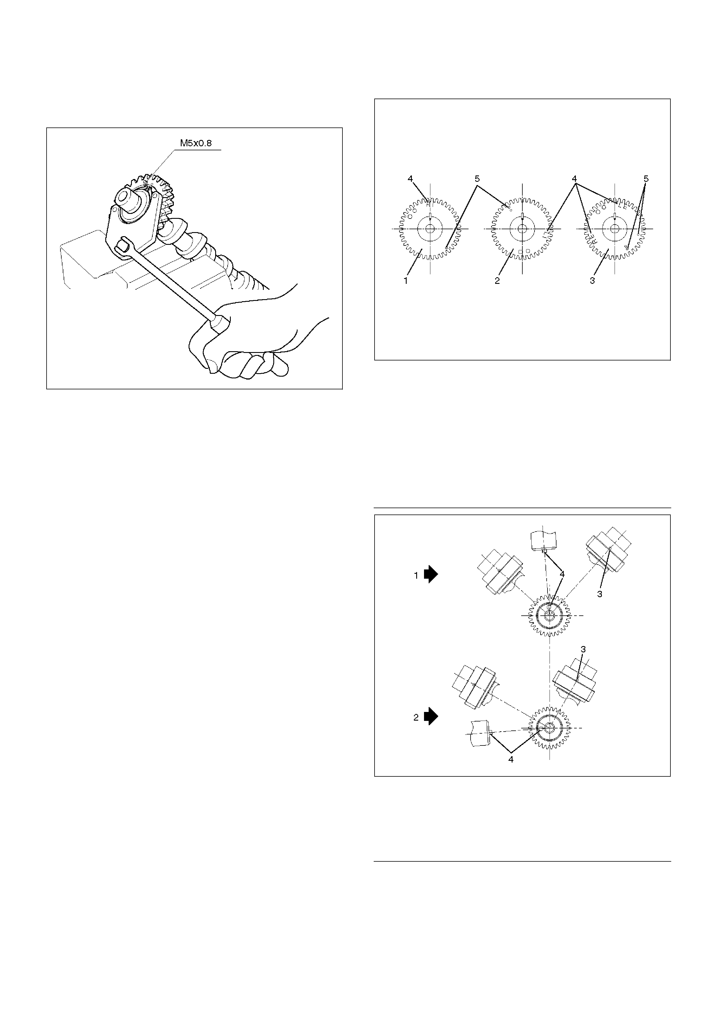
2. Tighten the M5 bolt to a suitable torque to
prevent the sub gear from moving .
014RW025
3. Install camshaft drive gear assembly and tighten
three bolts to the specified torque.
Torque: 10 N·m (1.0 Kg·m/89 lb in)
4. Install camshaft assembly and camshaft brackets,
tighten twenty bolts on one side bank to the
specified torque.
1. Apply engine oil to camshaft journal and bearing
surface of camshaft bracket.
2. Align timing mark on intake camshaft (one dot
for right bank, two dots for left bank) and
exhaust camshaft (one dot for right bank, two
dots for left bank) to timing mark on camshaft
drive gear (one dot).
014RW020
EndOFC allout
014RW023
EndOFC allout
Legend
(1) Intake Camshaft Timing Gear for Right Bank
(2) Intake Camshaft Timing Gear for Left Bank
(3) Exhaust Camshaft Timing Gear
(4) Discrimination Mark
LI: Left Bank Intake
RI: Right Bank Intake
LE: Left Bank Exhaust
RE: Right Bank Exhaust
Legend
(1) Right Bank Camshaft Drive Gear
(2) Left Bank Camshaft Drive Gear
(3) Timing Mark on Drive Gear
(4) Dowel Pin
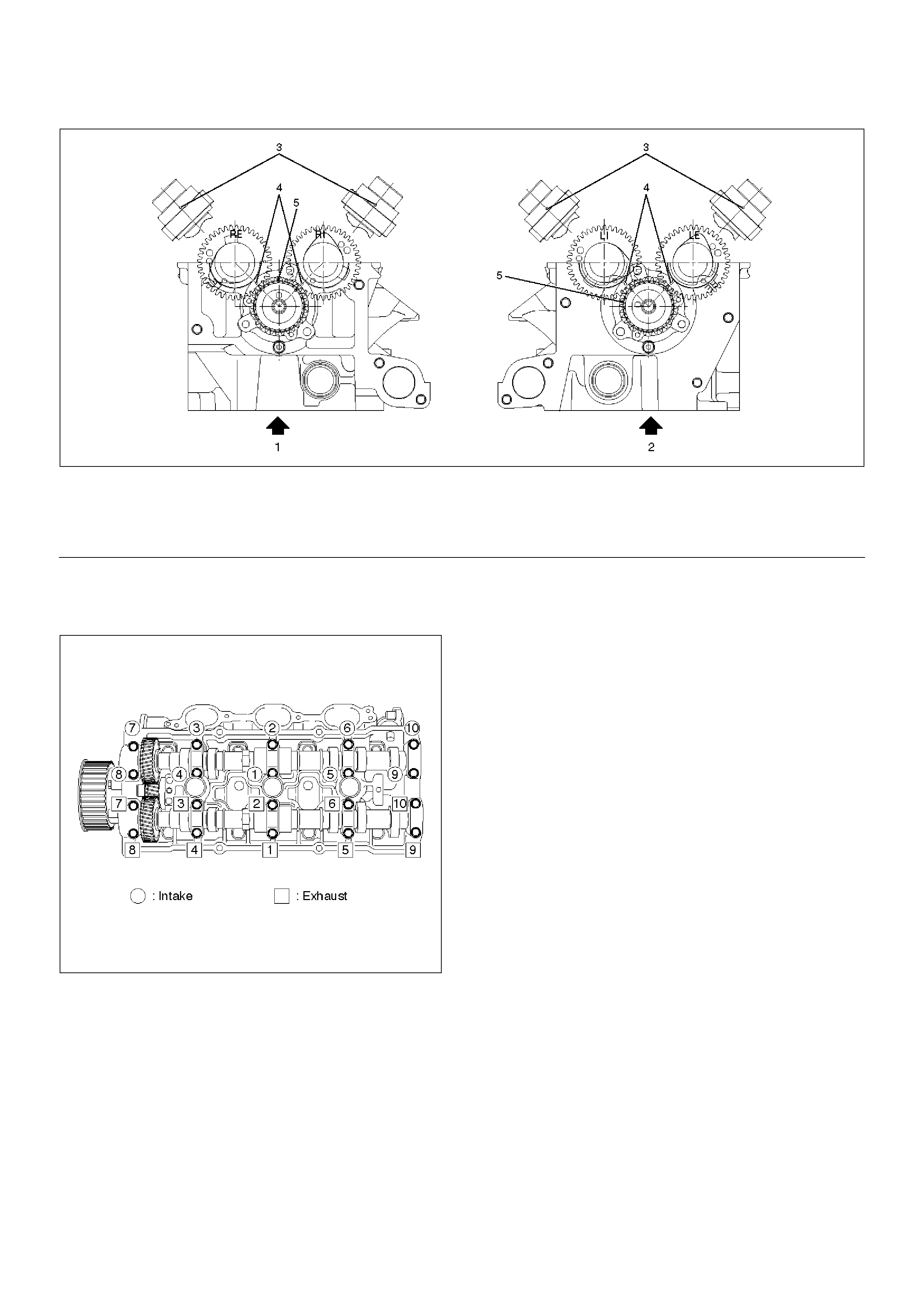
014RW024
EndOFC allout
3. Tighten twenty bolts in numerical order on one
side bank as shown in the illustration.
Torque: 10 N·m (1.0 Kg·m/89 lb in)
014RW031
5. Tighten bolt for camshaft drive gear assembly pulley
to the specified torque.
Torque: 98 N·m (10.0 Kg·m/72 lb ft)
Legend
(1) Right Bank
(2) Left Bank
(3) Alignment Mark on Camshaft Drive Gear
(4) Alignment Mark on Camshaft
(5) Alignment Mark on Retainer
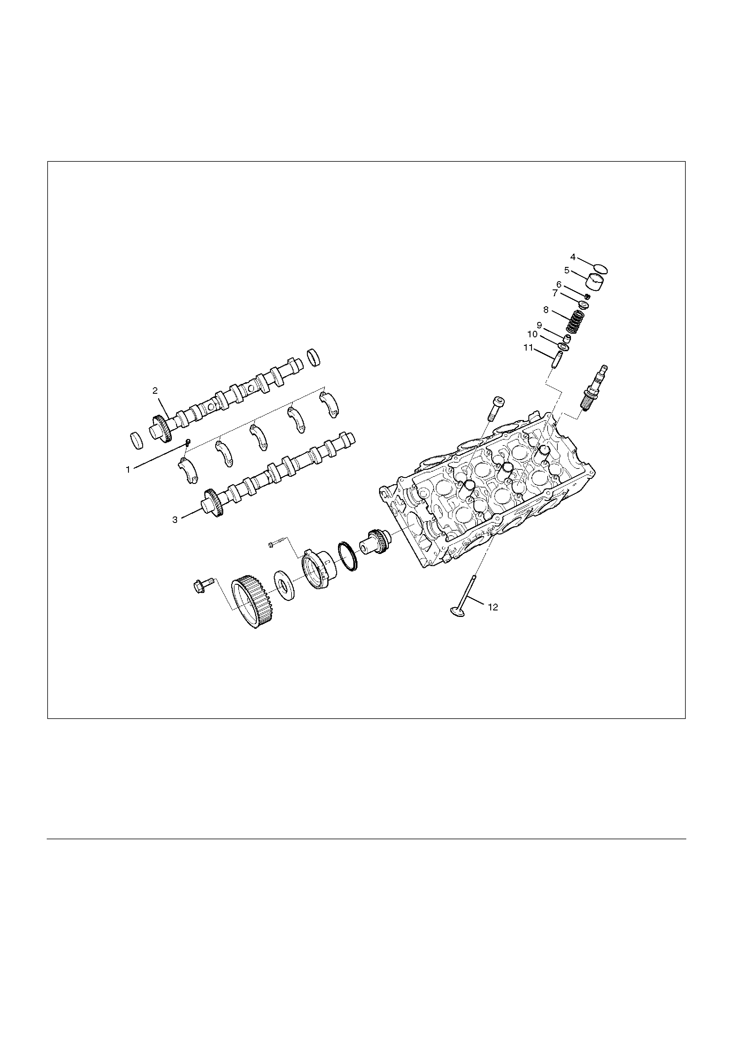
Valve Spring, Oil Controller, Valve, Valve Guide
Valve Spring, Oil Controller, Valve, Valve Guide and Associated Parts
014RW039
EndOFCallout
Disassembly
1. Remove camshaft bracket fixing bolts (1).
2. Remove camshaft assembly (intake).
3. Remove camshaft assembly (Exhaust side).
4. Remove shim (4) and tappet (5).
Legend
(1) Camshaft Bracket Fixing Bolts
(2) Camshaft Assembly Inlet
(3) Camshaft Assembly Exhaust
(4) Shim
(5) Tappet
(6) Split Collar
(7) Spring Upper Seat
(8) Valve Spring
(9) Oil Controller
(10) Spring Lower Seat
(11) Valve Guide
(12) Valve
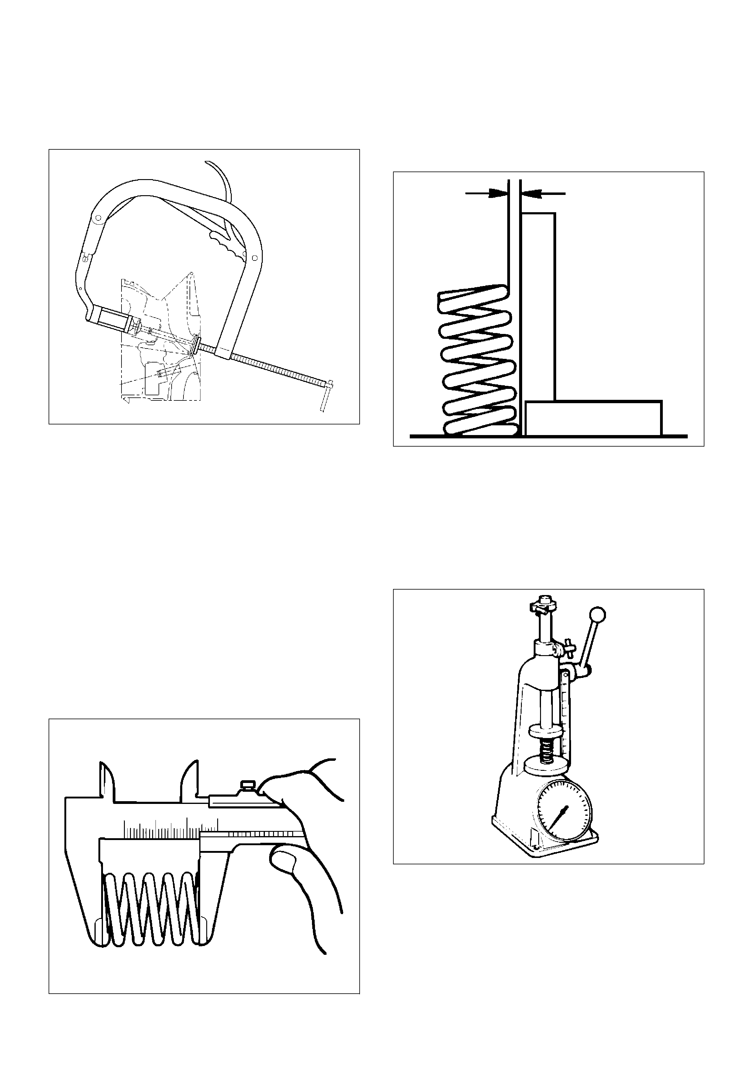
5.Use 5–8840–2446–0 valve spring compressor and
5–8840–2547–0 valve spring compressor adapter
to remove split collar.
014RW042
6.Remove valve spring.
7.Remove valve.
8.Remove oil controller and spring lower seat.
9.Remove the valve guide using the 5–8840–2442–0
valve guide replacer.
Inspection and Repair
Valve Spring
CAUTION: Visually inspect the valve springs and
replace them if damage or abnormal wear is
evident.
1.Measure the free height of the springs. The springs
must be replaced if the free height is below the
specified limit.
Standard : 44.6 mm (1.7559 in)
Limit : 43.6 mm (1.7165 in)
014RS004
2.Measure the valve spring squareness with a steel
square and replace the valve springs if the
measured value exceeds the specified limit.
Limit : 2 mm (0.0787 in)
014RS005
3.Using a spring tester to compress the springs to the
installed height, measure the compressed spring
tension, and replace the springs if the measured
tension is below the specified limit.
At installed height: 35.0 mm (1.38 in)
Standard: 196 N (44 lb)
Limit: Less than 181 N (41 lb)
014RS006
Valve Guide
CAUTION: Take care not to damage the valve seat
contact surface, when removing carbon adhering to
the valve head. Carefully inspect the valve stem for
scratchs or abnormal wear. If these conditions are
present, the valve and the valve guide must be
replaced as a set.
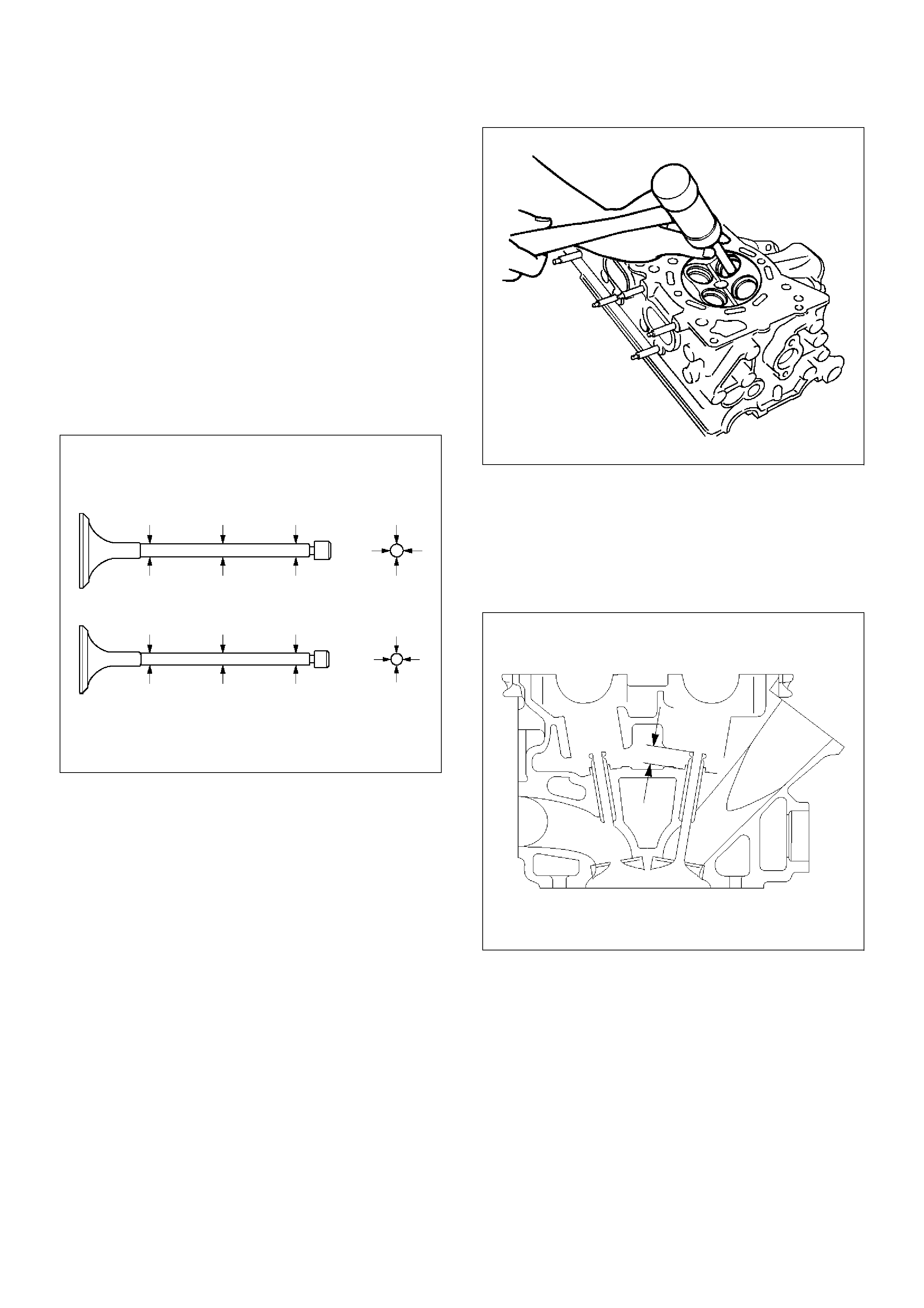
1. Measure the valve stem diameter with a
micrometer. If the valve stem diameter is less than
the specified limit, the valve and the valve guide
must be replaced as a set.
Diameter of Valve Stem
Intake
Standard : 5.977 mm–5.959 mm
(0.2353 in–0.2346 in)
Limit : 5.90 mm (0.2323 in)
Exhaust
Standard : 5.952 mm–5.970 mm
(0.2343 in–0.2350 in)
Limit : 5.90 mm (0.2323 in)
014RS007
2. Measure the inside diameter of the valve guide with
a micrometer. Subtract the measured outer
diameter of the valve stem from the measured inner
diameter of the valve guide. If the value exceeds the
specified limit, the valve and the valve guide must
be replaced as a set.
Inside Diameter of the Vale Guide
Inlet clearance
Standard : 0.023 mm–0.056 mm
(0.0009 in–0.0002 in)
Limit : 0.20 mm (0.00787 in)
Exhaust clearance
Standard : 0.030 mm–0.063 mm
(0.0012 in–0.0025 in)
Limit : 0.20 mm (0.00787 in)
Valve Guide Replacement
1. Using Valve guide replacer: 5–8840–2442–0, drive
out the valve guide from the combustion chamber
side.
014RS008
2. Apply engine oil to the outside of the valve guide.
Using valve guide replacer 5–8840–2442–0, drive in
a new valve guide from the camshaft side, and
check the valve guide height.
Valve guide upper end height: 13.0 mm (0.5118 in)
(Measured from the cylinder head upper face)
014RW046
3. Check the clearance. If the clearance is less than
the specified value, ream the inside diameter of
valve guide. Using a sharp 6 mm reamer, ream the
valve guide to obtain the specified clearance.
Valve Seat
1. Measure the protrusion of the valve stem when a
new valve is installed in the cylinder head. If the
protrusion of the valve stem exceeds the limit,
replace the valve seat insert or the cylinder head
assembly.
Protrusion of valve stem
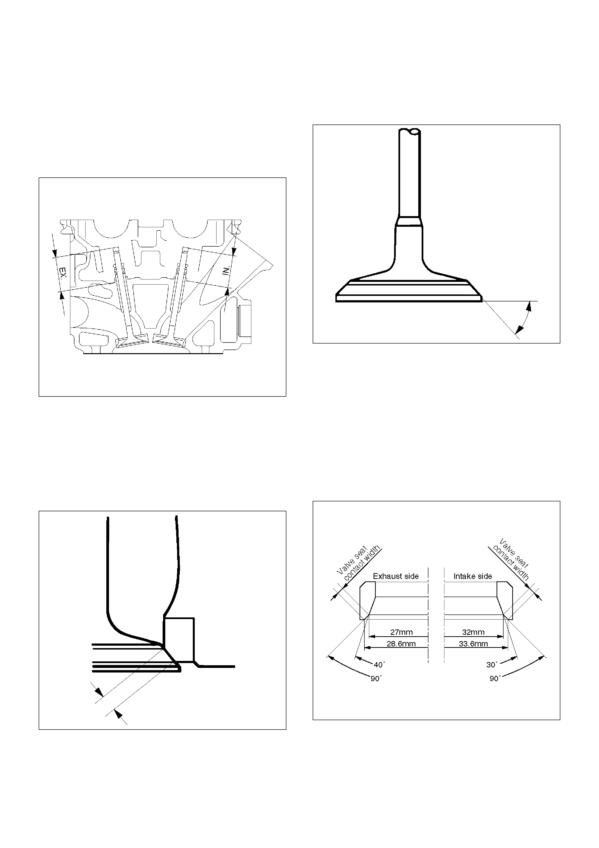
Intake
Standard: 39.32 mm (1.5480 in)
Limit: 39.47 mm (1.5539 in)
Exhaust
Standard: 39.30 mm (1.5472 in)
Limit: 39.45 mm (1.5531 in)
014RW047
2. Measure the valve seat contact width. Make the
necessary corrections if the seat contact surface is
damaged or rough or if the contact width wear
exceeds the limit.
Valve seat contact width
Standard: 1.1 mm (0.0433 in)
Limit: 1.7 mm (0.0669 in)
014RS011
Contact Surface Angle on Valve Seat on
Valve
1. Measure contact surface angle on valve seat.
2. If the measured value exceeds the limit, replace
valve, valve guide and valve seat as a set.
Valve contact surface angle: 45°
014RS012
Valve Seat Insert Correction
1. Remove the carbon from the valve seat insert
surface.
2. Use a valve cutter to minimize scratches and other
rough areas. This will bring the contact width back to
the standard value. Remove only the scratches and
rough areas. Do not cut away too much. Take care
not to cut away unblemished areas of the valve seat
surface.
Valve seat angle degree: 90°
014RW059
3. Apply abrasive compound to the valve seat insert
surface.
4. Insert the valve into the valve guide.
5. Turn the valve while lapping it to fit the valve seat
insert.
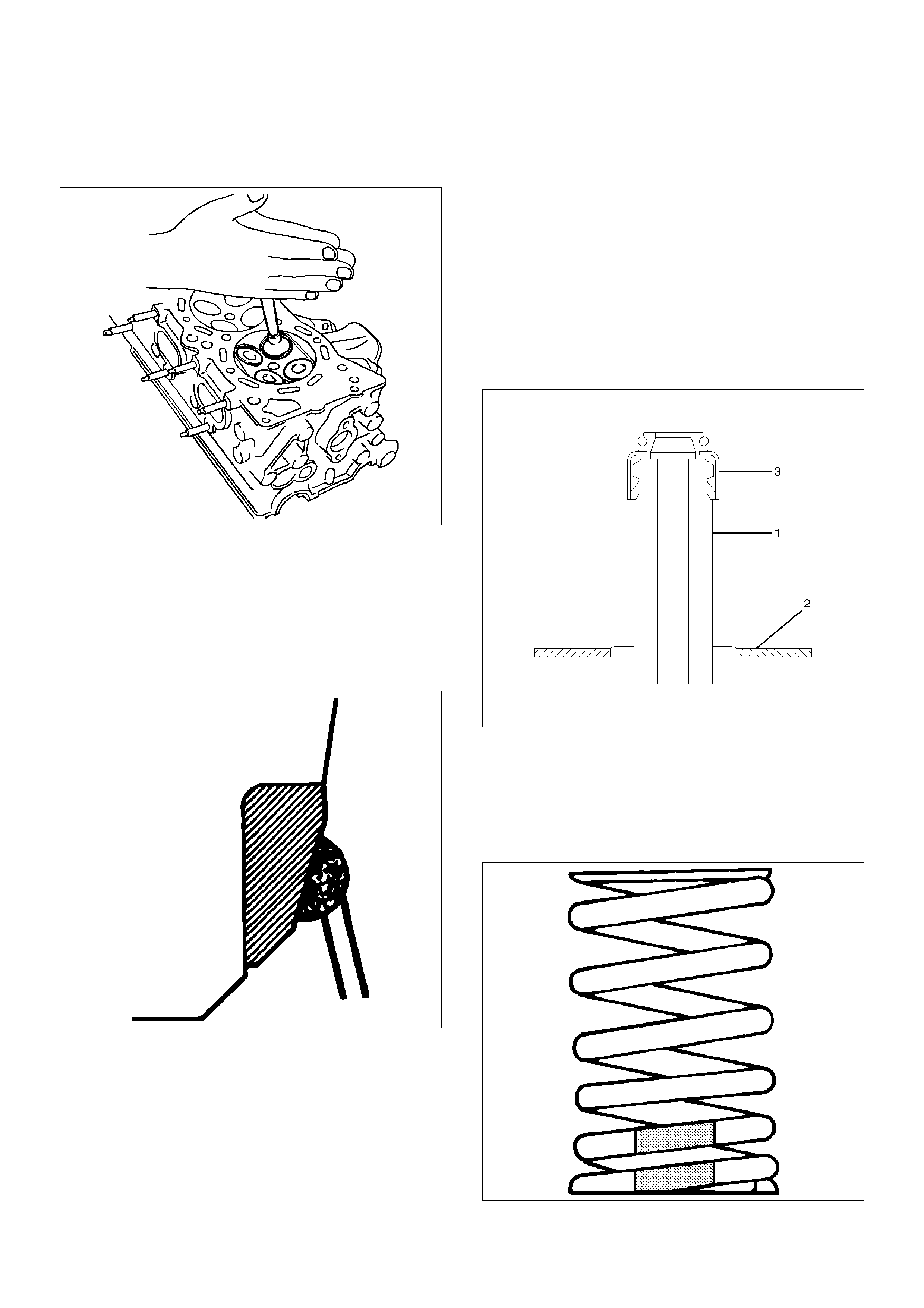
6. Check that the valve contact width is correct.
7. Check that the valve seat insert surface is in contact
with the entire circumference of the valve.
014RS014
Valve Seat Insert Replacement
1. Arc weld the rod at several points. Be careful not to
damage the aluminum section.
2. Allow the rod to cool for a few minutes. This will
cause the valve seat to shrink.
3. Strike the rod and pull it out.
014RS015
4. Carefully clean the valve seat press–fit section on
the cylinder head side.
5. Heat the press–fit section with steam or some other
means to cause expansion. Cool the valve seat with
dry ice or some other means.
6. Insert the press–fit section into the valve seat
horizontally.
Standard fitting interference: 0.14 mm–0.09 mm
(0.0055 in–0.0035 in)
7. After insertion, use a seat grinder to grind finish the
seating face. Carefully note the seating angle, the
contact width, and the depression.
8. Lap the valve and the seat.
Reassembly
1. Install valve guide (1) to cylinder head. Apply engine
oil to the outside of the valve guide. Using valve
guide replacer 5–8840–2442–0, drive in a new
valve guide from the camshaft side.
2. Install oil controller (3) and spring lower seat (2).
Using oil controller replacer 5–8840–0623–0, drive
in a new oil controller.
014RW058
3. Install valve to valve guide. Before install valve
guide apply engine oil to the outside of the valve
stem.
4. Install valve spring to cylinder head. Attach the
valve spring to the lower spring seat. The painted
area of the valve spring should be facing downward.
014RS020
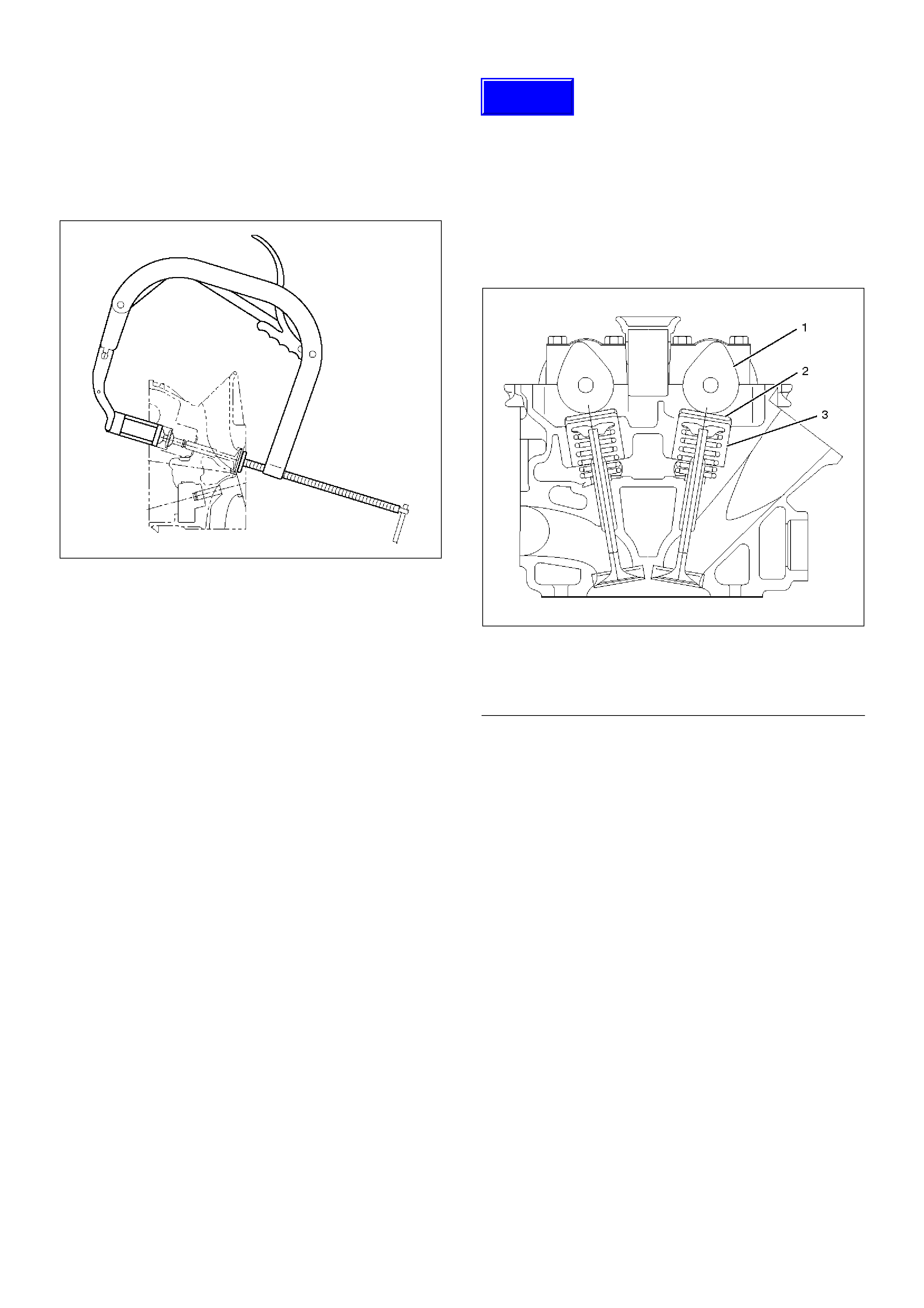
5.Install lower valve spring seat, valve spring and
upper valve spring seat then put split collars on the
upper spring seat, using the 5–8840–2446–0 valve
spring compressor and 5–8840–2547–0 valve
spring compressor adapter to install the split collars.
014RW042
6.Install tappet with shim.
7.Install camshaft assembly.
•Refer to installation procedure for Camshaft in
this manual.
Valve Clearance Adjustments
NOTE: To adjust valve clearance, apply engine oil to
the cam as well as to the adjusting shim (2) with the
cylinder head built on the cylinder block, give a few
turns to the camshaft by means of timing pulley
tightening bolt, and measure valve clearance when the
nose of cam is just opposite to maximum cam lift (1) as
shown in illistration below.
014RW081
EndOFC allout
Valve Clearance Standard Value (cold)
Intake: 0.23 mm-0.33 mm
(0.0091 in-0.0130 in)
Exhaust: 0.25 mm-0.35 mm
(0.0098 in-0.0138 in)
Selection of Adjusting Shim
Shim to be selected = (Thickness of removed shim) +
(Valve clearance measurement – Standard valve)
Based on the above formula, the best suited shim
should be selected from 41 sorts of shim (differently
thick at 0.02mm (0.0008 in) intervals from 2.40mm
(0.0945 in) through 3.2mm (0.1260 in) thick). Install the
shim and check valve clearance.
Legend
(1) Cam
(2) Shim
(3) Tappet
Techline
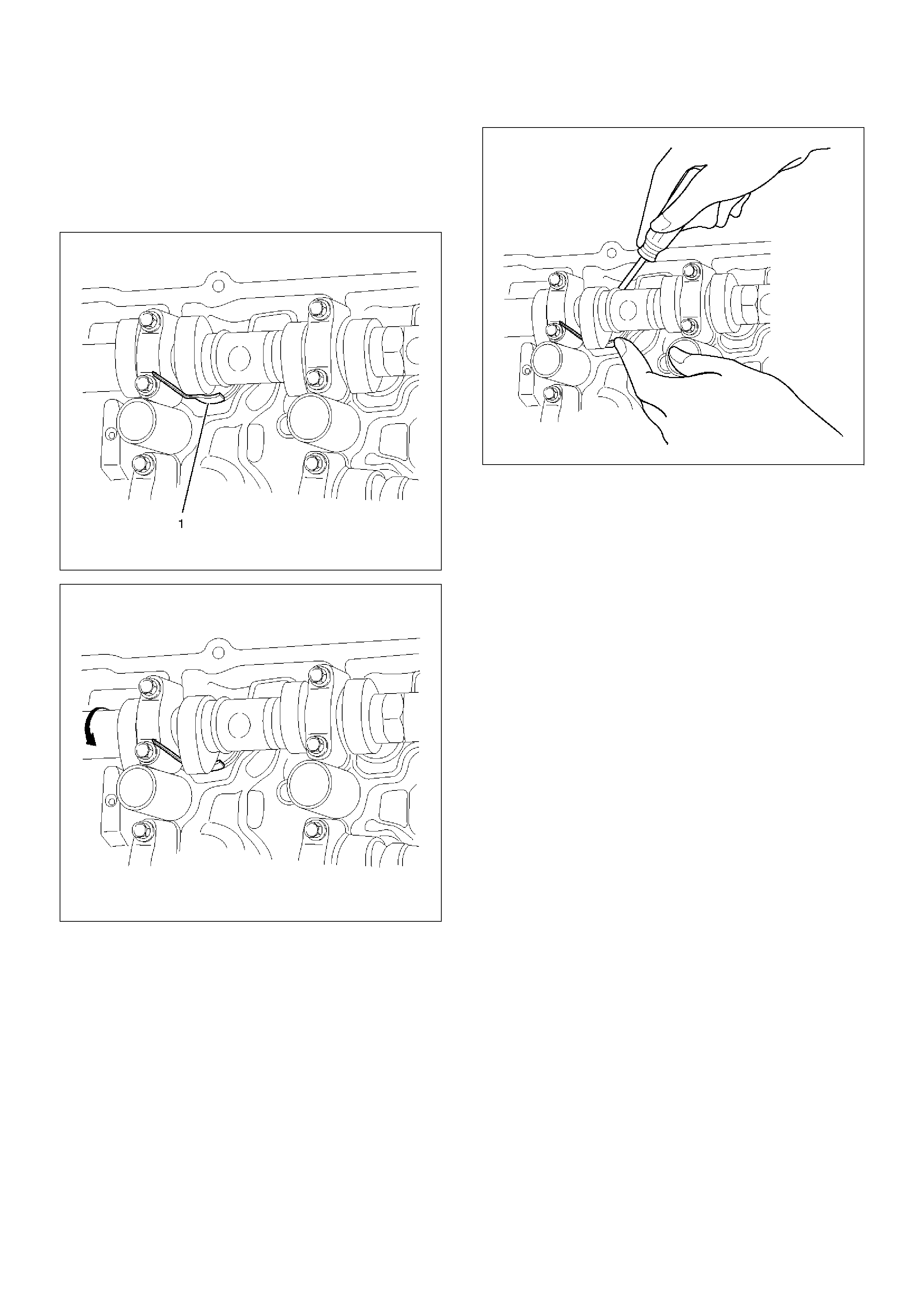
Replacement of Shim
Let the cam push down the edge of tappet by using 5–
8840–2444–0 valve clearance adjusting tool and push
out the shim with a flat blade screw driver as shown in
illustrations below.
014RW082
014RW083
014RW084
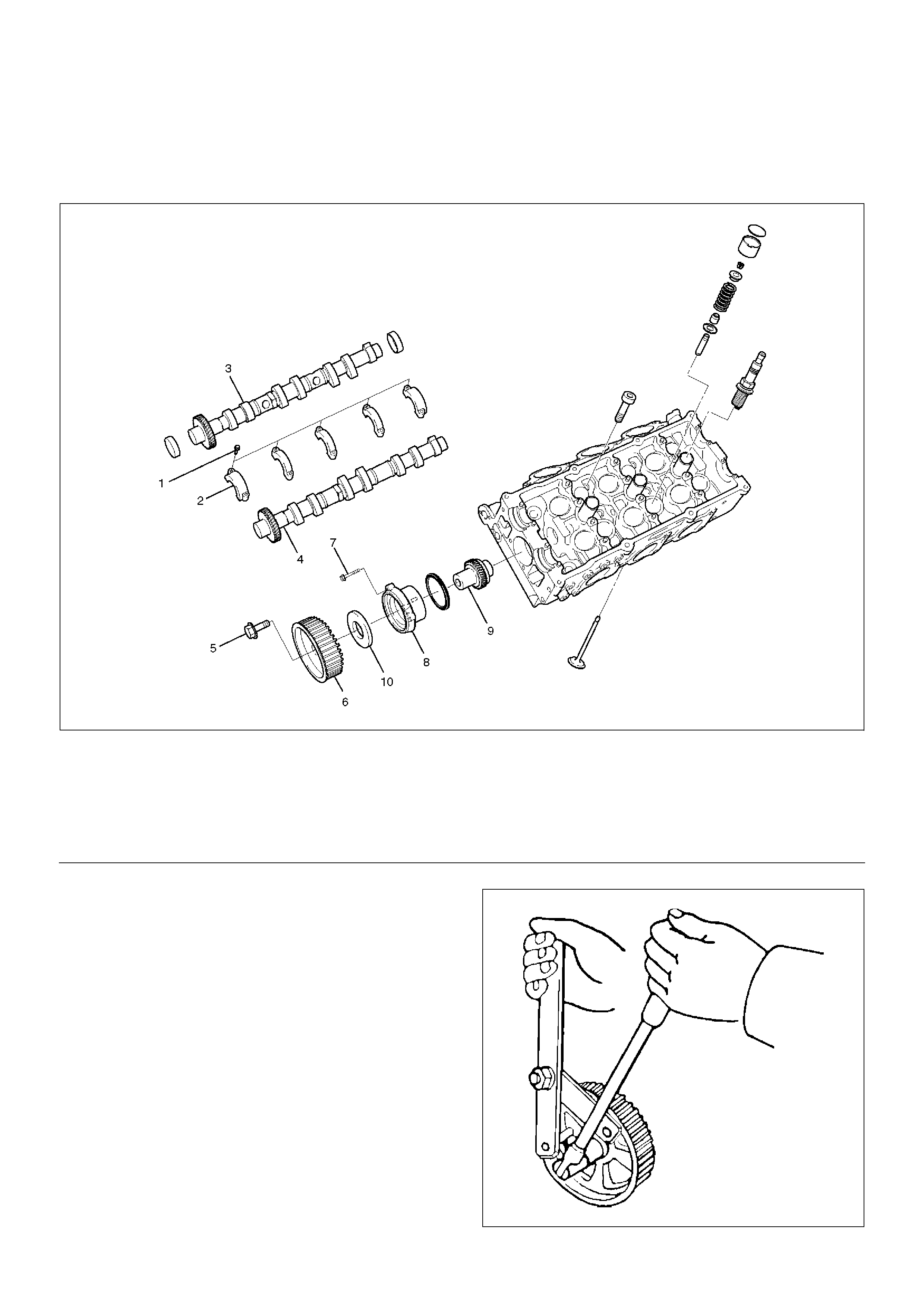
Camshaft
Camshaft and Associated Parts
014RW040
EndOFCallout
Disassembly
1. Remove fixing bolt (5) for camshaft drive gear pulley
using the 5–8840–2447–0 universal holder.
014RW060
Legend
(1) Camshaft Bracket Fixing Bolt
(2) Camshaft Bracket
(3) Camshaft Assembly Intake
(4) Camshaft Assembly Exhaust
(5) Pulley Fixing Bolt
(6) Camshaft Drive Gear Pulley
(7) Retainer Fixing Bolt
(8) Retainer
(9) Camshaft Drive Gear
(10) Oil Seal
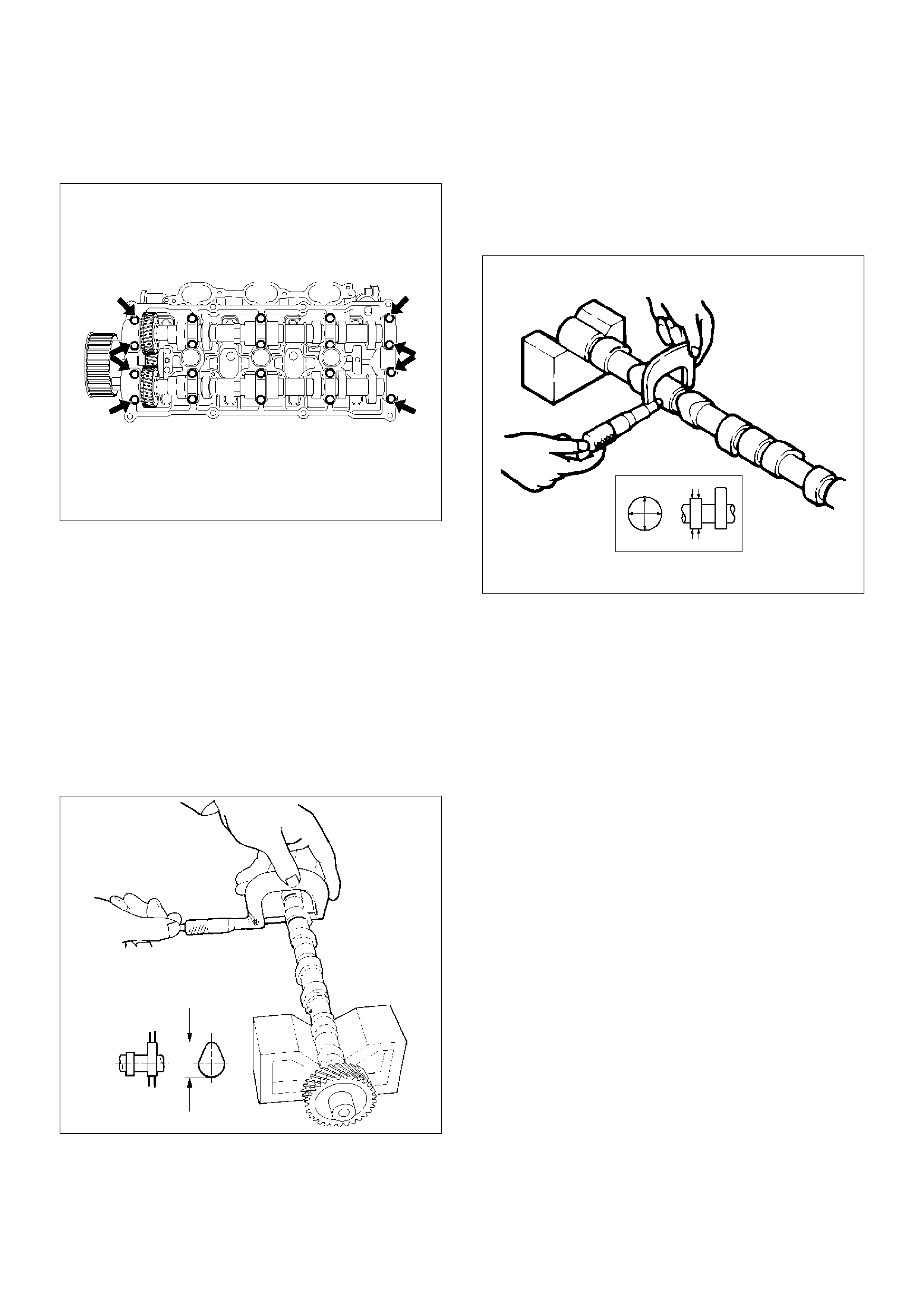
2. Remove twenty fixing bolts from inlet and exhaust
camshaft bracket on one side bank, then camshaft
brackets (2).
014RW027
3. Remove camshaft assembly (3), (4).
4. Remove three fixing bolts (7) from camshaft drive
gear retainer (8), then camshaft drive gear
assembly.
Inspection and Repair
1. Use a micrometer to measure the cam lobe height
and uneven wear. Replace the camshaft if either the
lobe height or the uneven wear exceeds the
specified limit.
Lobe height : 44.709 mm (1.7602 in)
Uneven wear : 0.05 mm (0.0020 in)
014RW043
2. Use a micrometer to measure the diameter and the
uneven wear of the camshaft journals.
Replace the camshaft if the diameter or the uneven
wear exceeds the specified limit.
Journal Diameter
Standard : 25.972 mm–25.993 mm
(1.0225 in–1.0233 in)
Limit : 25.8 mm (1.0157 in)
Uneven wear : 0.05 mm (0.0020 in)
014RS023
3. Place the camshaft on V–blocks.
Slowly rotate the camshaft and measure the runout
with a dial indicator.
Replace the camshaft if the runout exceeds the
specified limit.
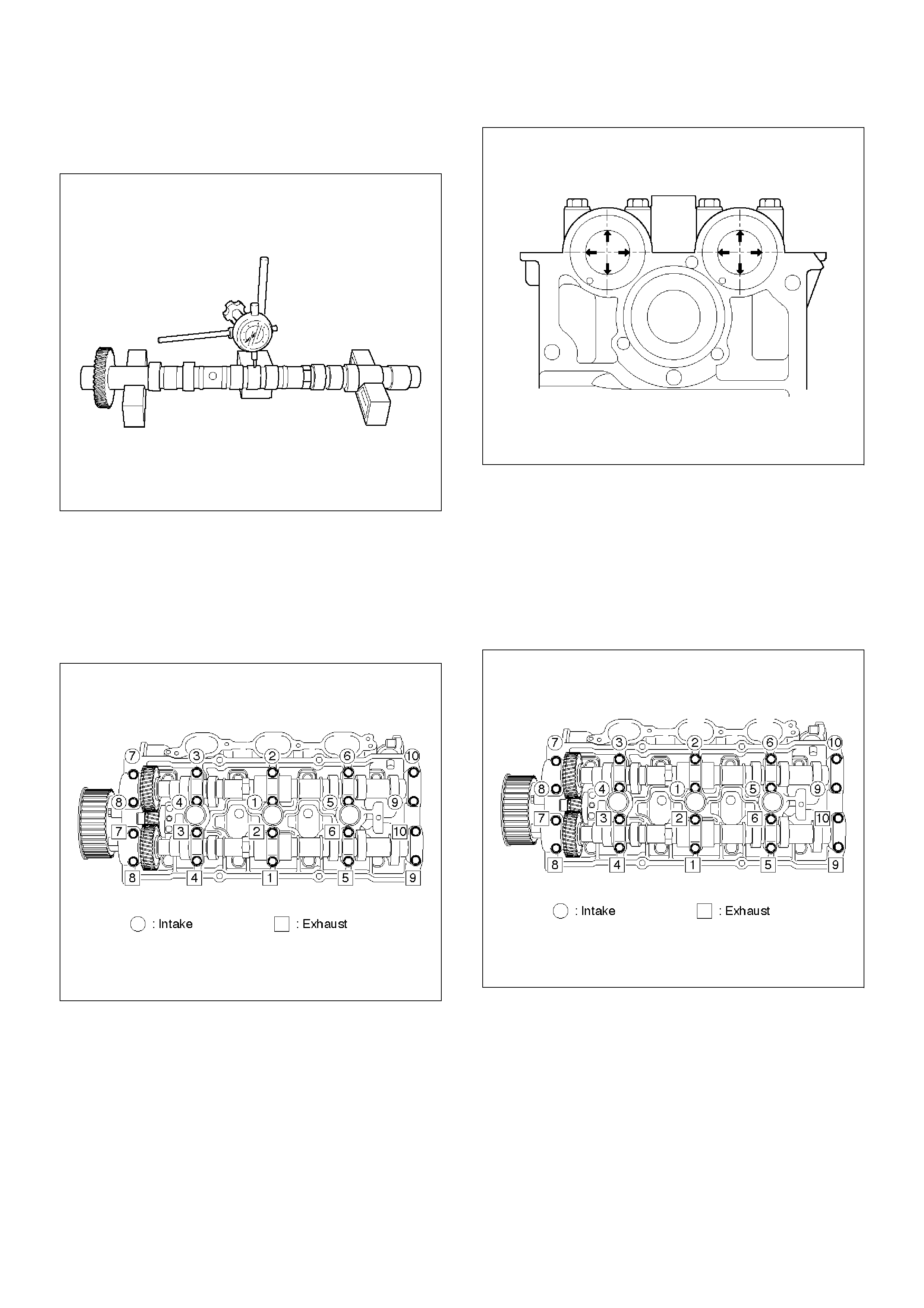
Runout
Limit : 0.1 mm (0.0039 in)
014RW044
4. Measure the camshaft journal oil clearance.
1. Measure the camshaft bracket housing inside
diameter.
NOTE: Tighten camshaft bracket (2) to specified torque
before measuring the camshaft bracket inside diameter.
Torque : 10 N·m (1.0 Kg·m/89 lb in)
014RW031
2. Subtract the camshaft outside diameter from the
camshaft bracket housing inside diameter.
Oil Clearance
Standard : 0.027 mm–0.078 mm
(0.0011 in–0.0031 in)
Limit : 0.11 mm (0.0043 in)
014RW037
5. Replace the cylinder head and/or camshaft if the
measured oil clearance exceeds the specified limit.
1. Carefully clean the camshaft journal, the
camshaft bracket, and the cylinder head.
2. Install camshaft assembly and camshaft
brackets (2), tighten twenty bolts (1) on one side
bank to the specified torque.
Torque: 10 N·m (1.0 Kg·m/89 lb in)
014RW031
3. Measure the camshaft thrust clearance with a
dial indicator. Replace the camshaft and/or the
cylinder head if the camshaft thrust clearance
exceeds the specified limit.
Camshaft thrust Clearance
Standard : 0.03 mm–0.08 mm
(0.0012 in.–0.0031 in.)
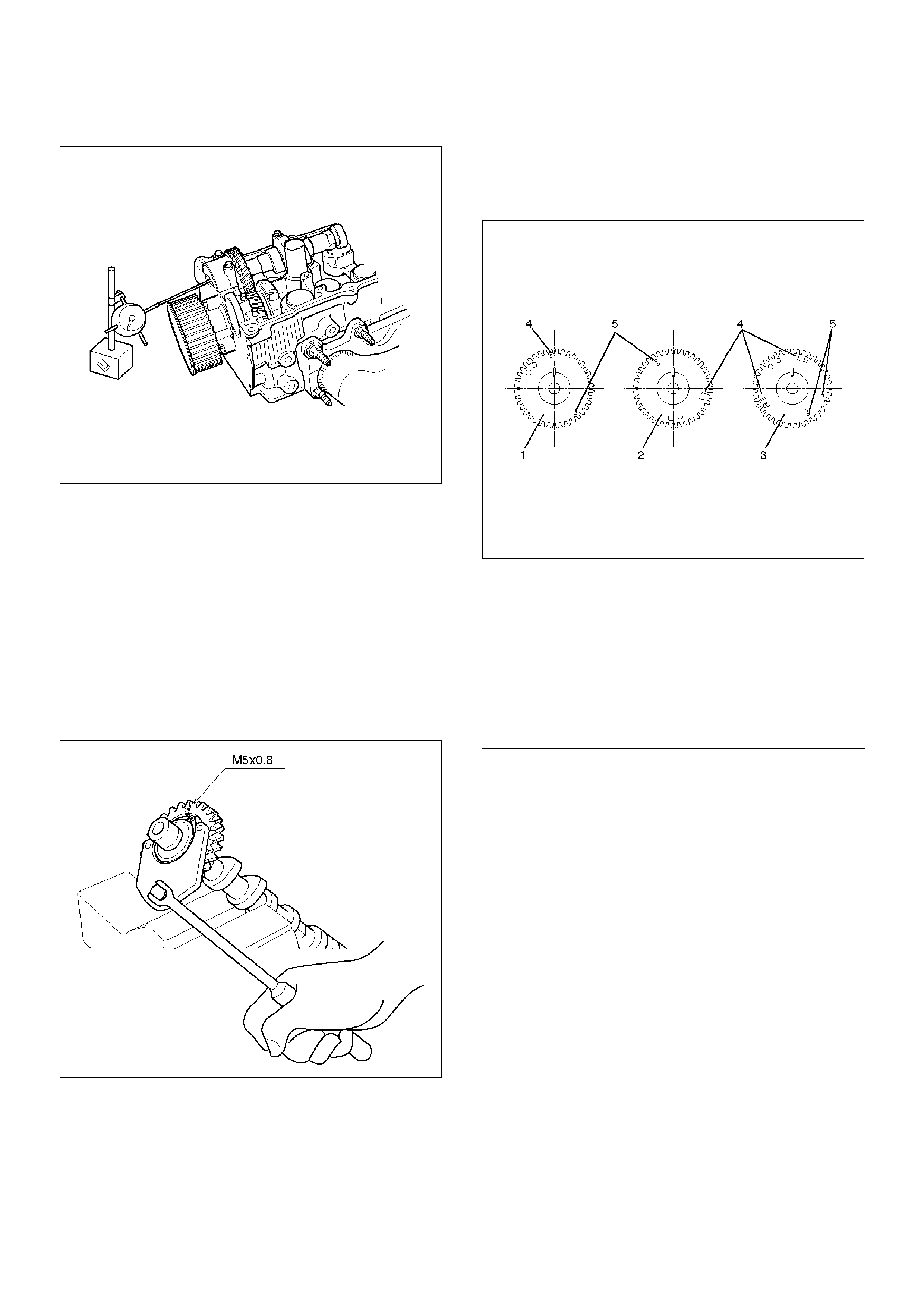
Limit : 0.12 mm (0.0047 mm)
014RW035
Reassembly
1. Install camshaft drive gear assembly and tighten
three bolts to specified torque.
Torque: 10 N·m (1.0 Kg·m/89 lb in)
2. Tighten sub gear setting bolt.
1. Use 5–8840–2443–0 to turn sub gear to right
direction until the M5 bolt hole aligns between
camshaft driven gear and sub gear.
2. Tighten M5 bolt suitable torque for prevent
moving the sub gear.
014RW041
3. Install camshaft assembly and camshaft brackets,
tighten twenty bolts on one side bank to the
specified torque.
1. Apply engine oil to camshaft journal and bearing
surface of camshaft bracket.
2. Align timing mark on intake camshaft (one dot
for right bank, two dots for left bank) and
exhaust camshaft (one dot for right bank, two
dots for left bank) to timing mark on camshaft
drive gear (one dot).
014RW020
EndOFC allout
Legend
(1) Intake Camshaft Timing Gear for Right Bank
(2) Intake Camshaft Timing Gear for Left Bank
(3) Exhaust Camshaft Timing Gear
(4) Discerning Mark
LI: Left Bank Intake
RI: Right Bank Intake
LE: Left Bank Exhaust
RE: Right Bank Exhaust
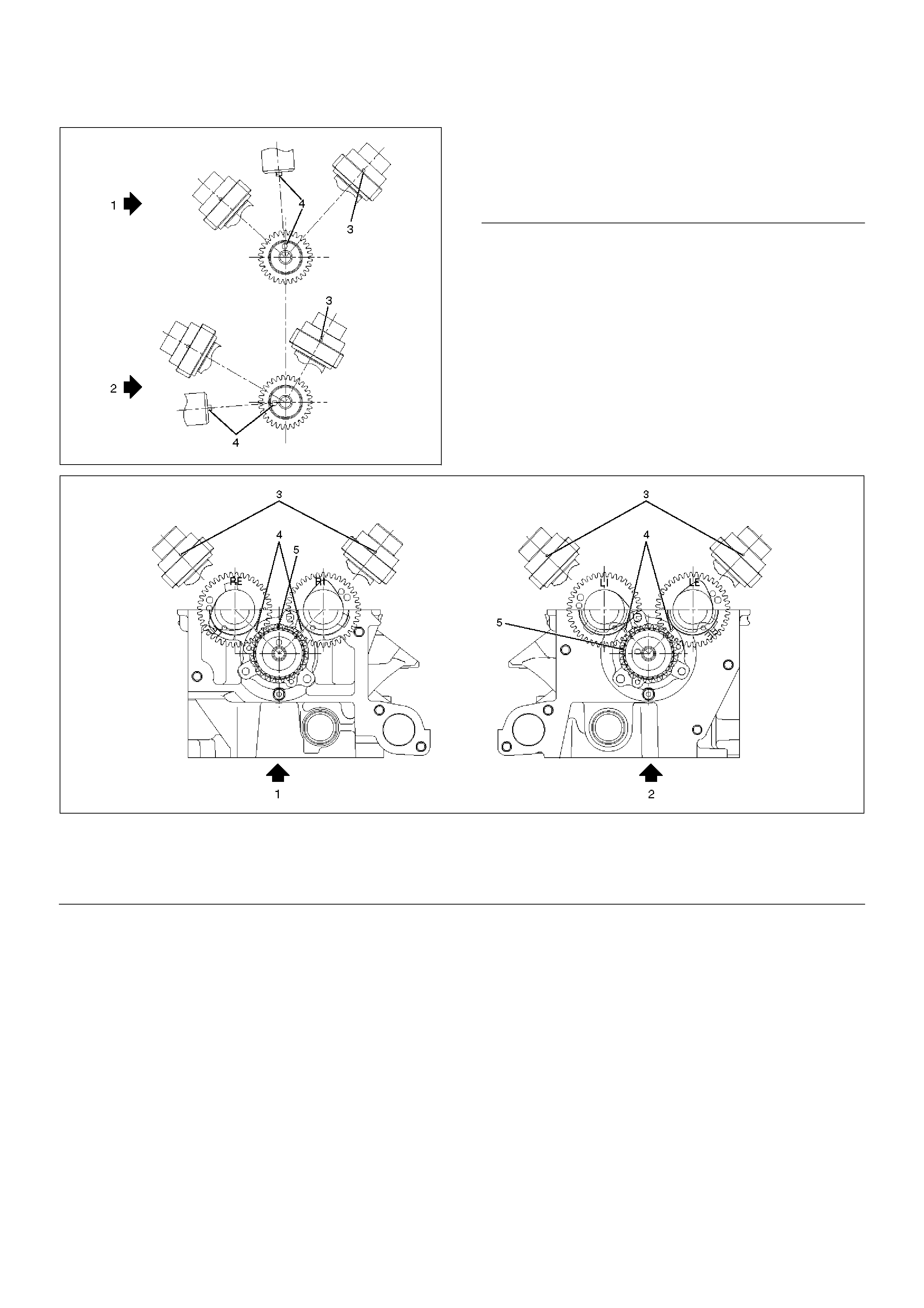
014RW023
EndOFC allout
014RW024
EndOFC allout
3. Tighten twenty bolts in numerical order on one
side bank as shown in the illustration.
Torque: 10 N·m (1.0 Kg·m/89 lb in)
Legend
(1) Right Bank Camshaft Drive Gear
(2) Left Bank Camshaft Drive Gear
(3) Timing Mark on Drive Gear
(4) Dowel Pin
Legend
(1) Right Bank
(2) Left Bank
(3) Alignment Mark on Camshaft Drive Gear
(4) Alignment Mark on Camshaft
(5) Alignment Mark on Retainer
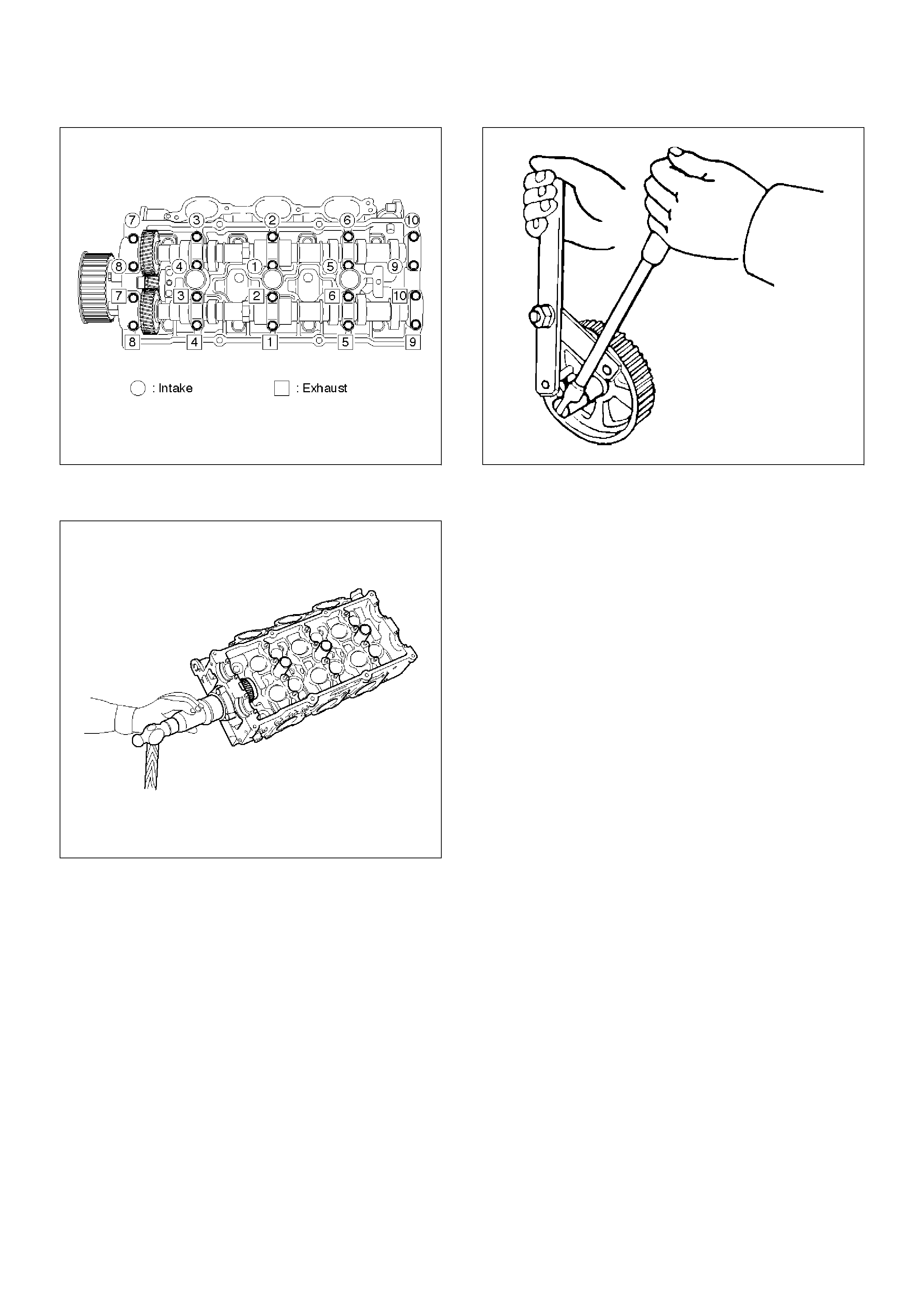
014RW031
4. If the oil seal requires replacement, use the 5–
8840–2445–0 to install the oil seal.
014RW034
5. Tighten bolt for camshaft drive gear pulley to the
specified torque using the 5–8840–2447–0
universal holder.
Torque: 98 N·m (10.0 Kg·m/72 lb ft)
014RW060
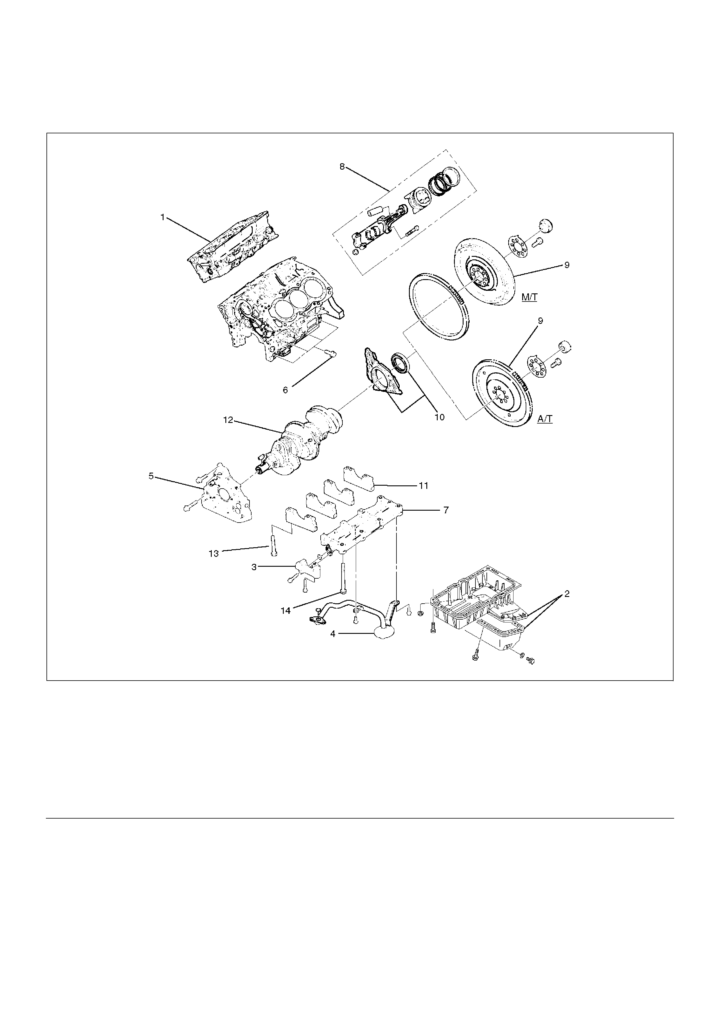
Crankshaft
Crankshaft and Associated Parts
013RW009
EndOFCallout
Disassembly
1.Remove cylinder head assembly (1). Refer to
“Cylinder Head” in this manual.
2.Remove crankcase with oil pan (2). Refer to “Oil
Pan and Crankcase” in this manual.
CAUTION: Take care not to damage or deform the
sealing flange surface of crankcase.
3. Remove oil pipe and O-ring (3).
4. Remove oil strainer and O-ring (4).
5. Remove oil pump assembly (5).
6. Remove crankcase side bolts (6).
7. Remove oil gallery (7).
8. Remove piston and connecting rod assembly (8).
Refer to “Piston, Piston Ring and Connecting Rod”
in this manual.
Legend
(1) Cylinder Head Assembly
(2) Crankcase with Oil Pan
(3) Oil Pipe and O-Ring
(4) Oil Strainer and O-Ring
(5) Oil Pump Assembly
(6) Cylinder Block Side Bolts
(7) Oil Gallery
(8) Piston and Connecting Rod Assembly
(9) Flywheel
(10) Rear Oil Seal Retainer and Oil Seal
(11) Main Bearing Cap
(12) Crankshaft
(13) Main Bearing Cap Fixing Bolts
(14) Oil Gallery Fixing Bolts
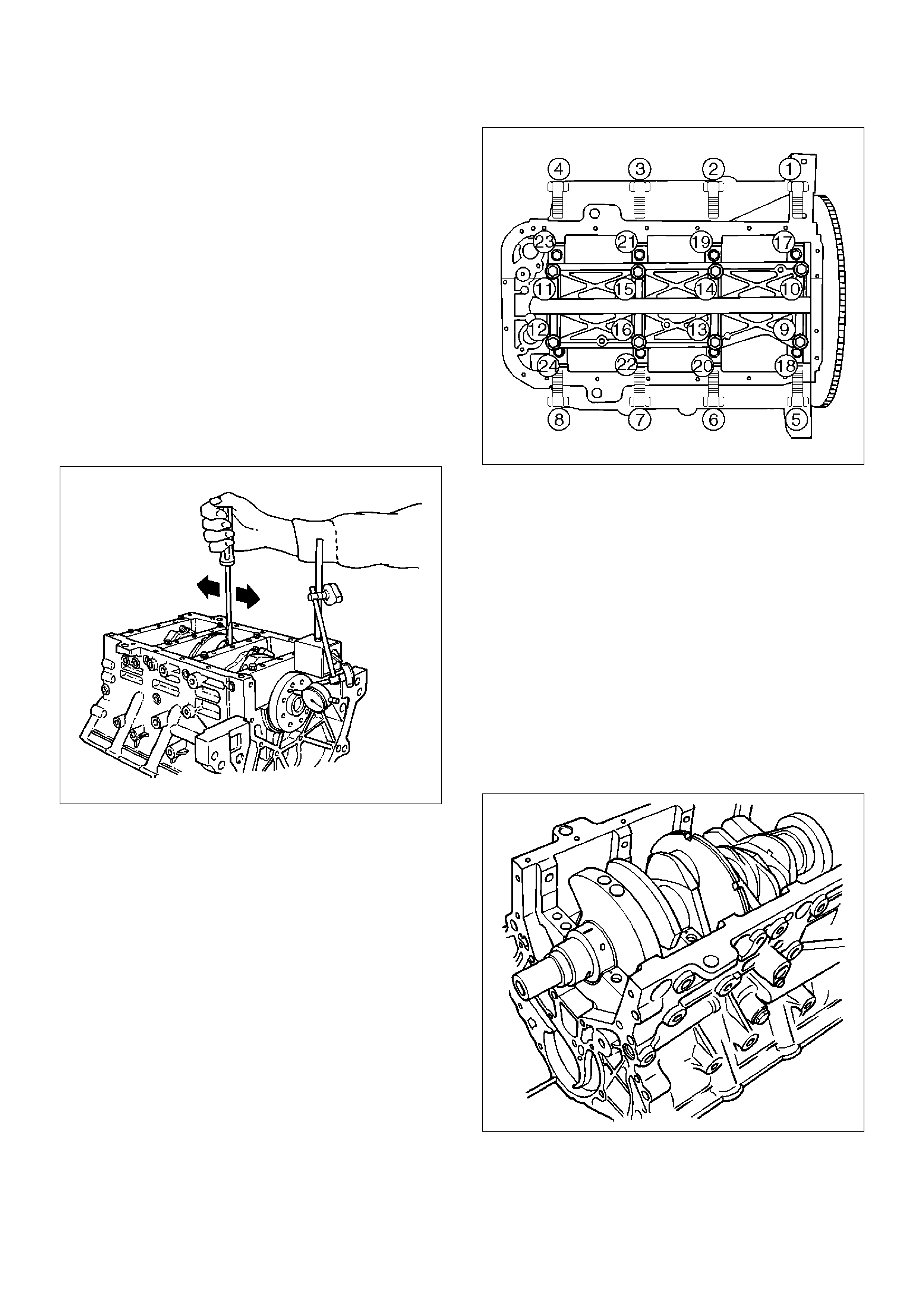
9. Remove flywheel (9).
10. Remove rear oil seal retainer (10).
11. Remove main bearing cap (11).
12. Remove crankshaft (12).
Inspection and Repair
1. Crankshaft
Set the dial indicator as shown in the illustration and
measure the crankshaft thrust clearance. If the
thrust clearance exceeds the specified limit, replace
the thrust bearings as a set.
Thrust Clearance
Standard : 0.06 mm–0.24 mm
(0.0024 in–0.0094 in)
Limit : 0.30 mm (0.0118 in)
015RS003
Main Bearing Clearance
1. Remove the bearing caps and measure the oil
clearance.
2. Remove the main bearing cap fixing bolts in the
sequence shown in the illustration.
Arrange the removed main bearing caps in the
cylinder number order.
Remove the main bearings.
015RS004
3. Remove the crankshaft.
Remove the main bearings.
4. Clean the upper and lower bearings as well as the
crankshaft main journal.
5. Check the bearings for damage or excessive wear.
The bearings must be replaced as a set if damage
or excessive wear is discovered during inspection.
6. Set the upper bearings and the thrust washers to
their original positions.
Carefully install the crankshaft.
7. Set the lower bearings to the bearing cap original
position.
8. Apply plastigage to the crankshaft journal unit as
shown in the illustration.
NOTE: Do not set the plastigage on the oil hole.
015RS005
9. Install main bearing caps, oil gallery and crank case
bolts in the order shown, and tighten each bolt to the
specified torque.
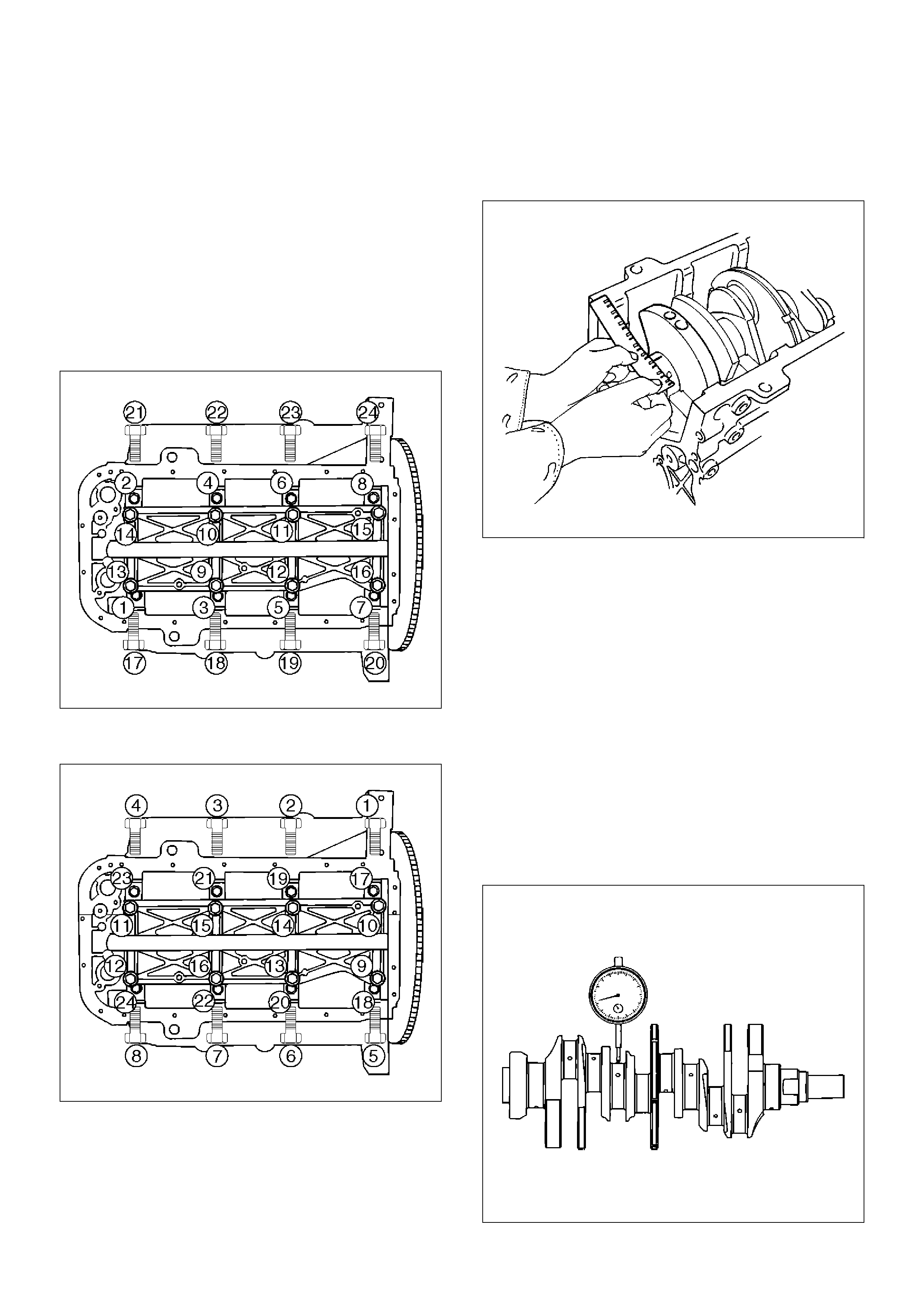
NOTE: Do not apply engine oil to the crank case side
bolts.
Main bearing cap bolts.
Torque: 39 N·m (4.0 Kg·m/29 lb ft)
Oil gallery fixing bolts.
Torque:
1st step: 29 N·m (3.0 Kg·m/21 lb ft)
2nd step 55°∼ 65°
Crank case side bolts
Torque : 39 N·m (4.0 Kg·m/29 lb ft)
NOTE: Do not allow the crankshaft to rotate.
015RS006
10. Remove the main bearing caps in the sequence
shown in the illustration.
015RS004
11. Measure the plastigage width and determine the oil
clearance. If the oil clearance exceeds the specified
limit, replace the main bearings as a set and/or
replace the crankshaft.
Standard : 0.019 mm–0.043 mm
(0.0007 in–0.0017 in)
Limit : 0.08 mm (0.0031 in)
015RS008
12. Clean the plastigage from the bearings and the
crankshaft.
Remove the crankshaft and the bearings.
Crankshaft (12) Inspection
Inspect the surface of the crankshaft journal and crank
pins for excessive wear and damage. Inspect the oil
seal fitting surfaces for excessive wear and damage.
Inspect the oil ports for obstructions.
Inspection and Repair
1. Carefully set the crankshaft on the V–blocks. Slowly
rotate the crankshaft and measure the runout. If the
crankshaft runout exceeds the specified limit, the
crankshaft must be replaced.
Runout : 0.04 mm (0.0016 in)
015RS007
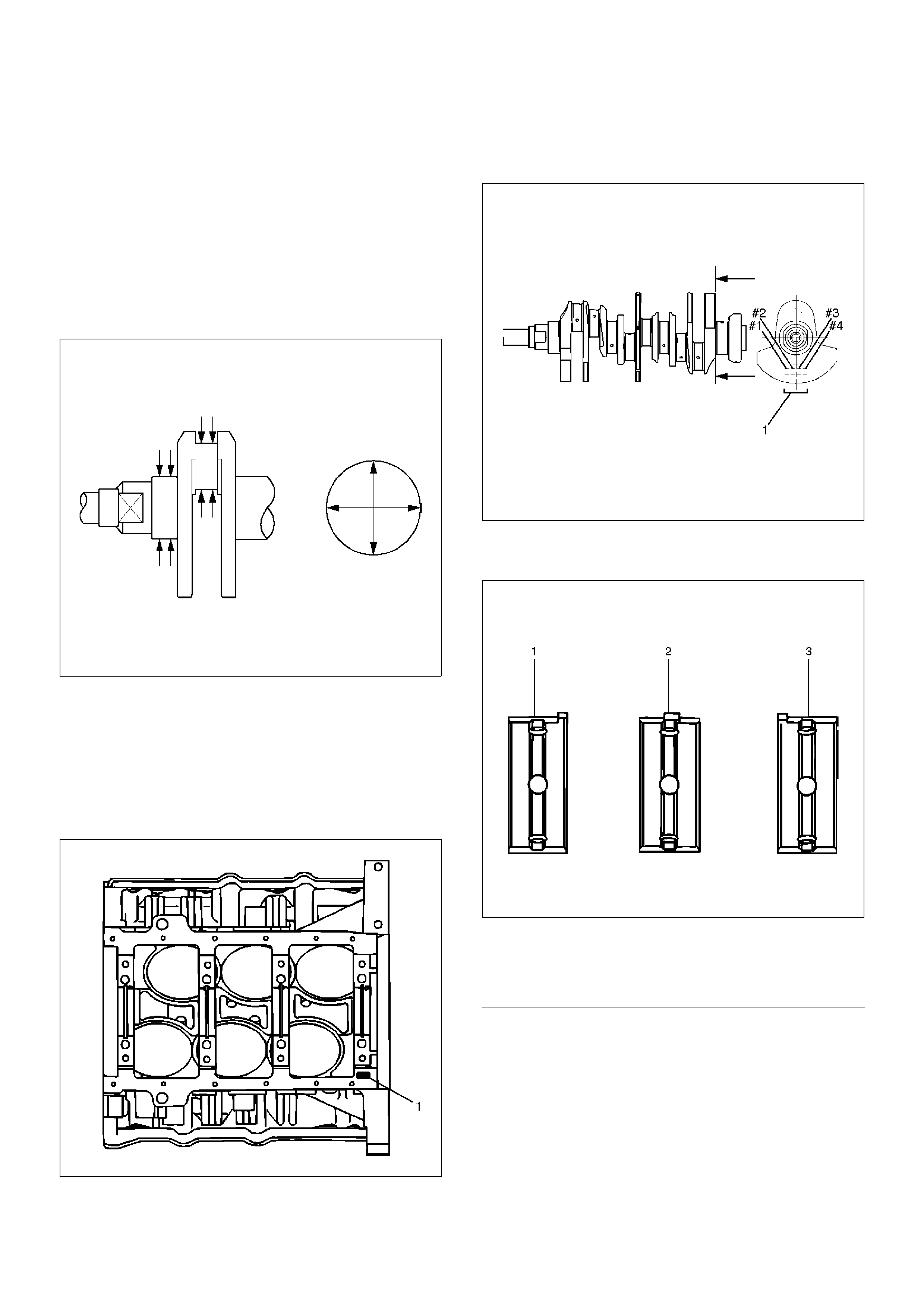
2. Measure the diameter and the uneven wear of main
journal and crank pin. If the crankshaft wear
exceeds the specified limit, crankshaft must be
replaced.
Main journal diameter : 63.918 mm–63.933 mm
(2.5165 in–2.5170 in)
Crank pin diameter : 53.922 mm–53.937 mm
(2.1229 in.–2.1235 in.)
Uneven wear limit : 0.005 mm (0.0002 in)
015RS009
Crankshaft Bearing Selection
When installing new crankshaft bearings or replacing
bearings, refer to the selection table below. Select and
install the new crankshaft bearings, paying close
attention to the cylinder block journal hole.
1. Diameter size mark (1) and the crankshaft journal.
015RS010
2. Diameter size mark (1).
The diameter size marks are stamped on the No.1
crankshaft balancer as shown in the illustration.
015RS011
NOTE: Take care to ensure the bearings are positioned
correctly.
015RS012
EndOFC allout
Legend
(1) Number 1 and 4 main bearing upper and lower
(2) Number 2 and 3 main bearing upper
(3) Number 2 and 3 main bearing lower
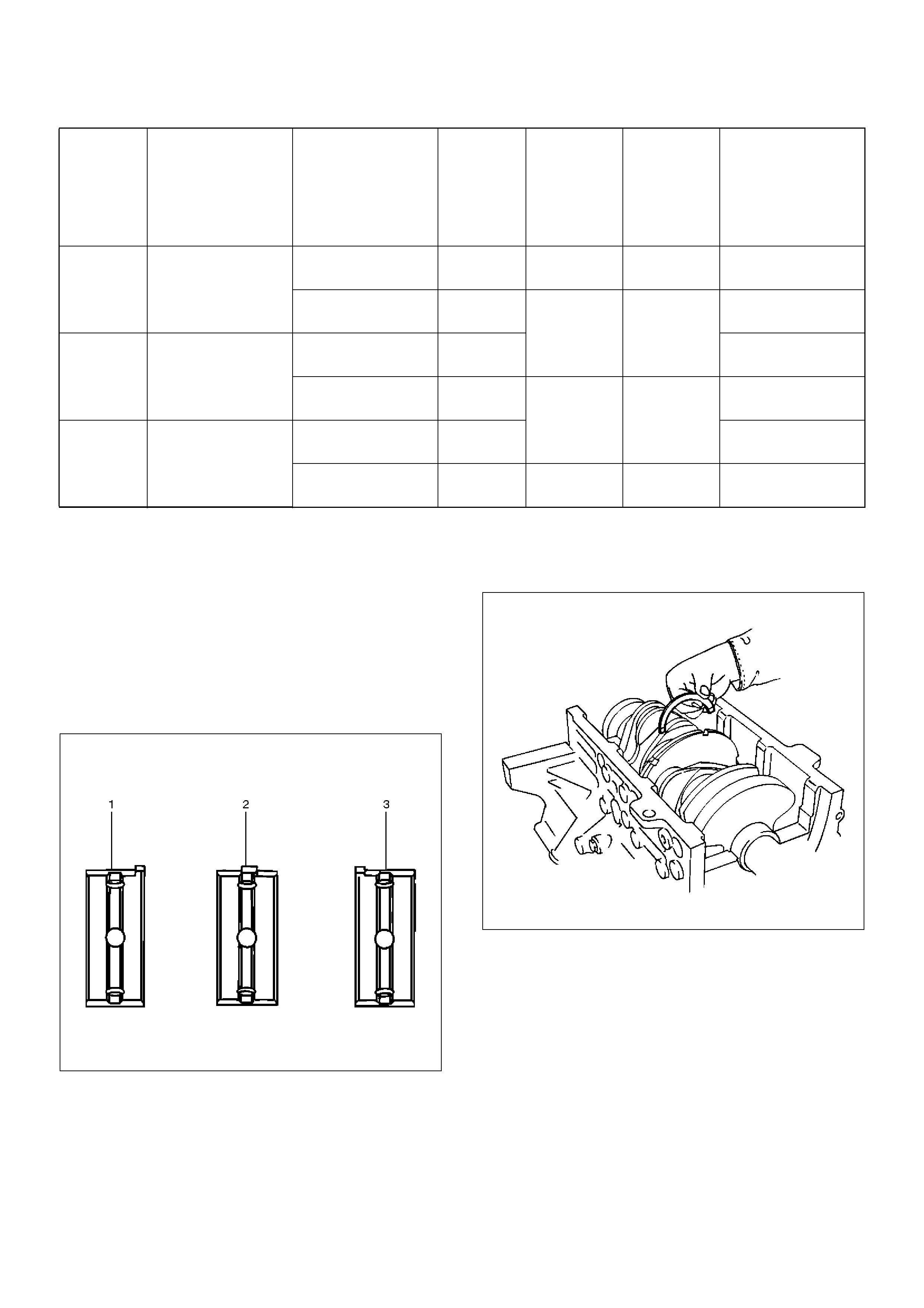
Reassembly
1. Crankshaft (12)
• Install the main bearings to the cylinder block and
the main bearing caps.
• Be sure that they are positioned correctly.
• Apply new engine oil to the upper and lower main
bearing faces.
NOTE: Do not apply engine oil to the main bearing
back faces.
015RS012
• Carefully mount the crankshaft.
• Apply engine oil to the thrust washer.
• Assemble the thrust washer to the No.3 bearing
journal. The oil grooves must face the crankshaft.
015RS013
2. Rear oil seal (10)
• Remove the oil from the cylinder block and the
retainer mounting surface.
• Apply sealant (TB–1207B or equivalent) to the
retainer mounting surface, following the pattern
shown in the illustration.
The retainer must be installed within 5 minutes
after sealant application befor the sealant
hardens.
1 Size
Mark
Main Bearing
Bore Diameter
Crank Shaft Main
Journal Diameter
2 Size
Mark
Crank
Shaft
Bearing
Size Mark
(Upper
Side)
Crank
Shaft
Bearing
Size Mark
(Lower
Side)
Oil Clearance
(Reference)
168.994-69.000
(2.7163-2.7165)
63.918-63.925
(2.5165-2.5167) 2BlueBlue
0.030-0.049
(0.0012-0.0019)
63.926-63.933
(2.5168-2.5170) 1
Brown Brown
0.028-0.047
(0.0011-0.0019)
268.987-68.993
(2.7160-2.7163)
63.918-63.925
(2.5165-2.5167) 20.029-0.048
(0.0011-0.0019)
63.926-63.933
(2.5168-2.5170) 1
Green Green
0.027-0.046
(0.0011-0.0018)
368.980-68.986
(2.7157-2.7160)
63.918-63.925
(2.5165-2.5167) 20.028-0.047
(0.0011-0.0019)
63.926-63.933
(2.5168-2.5170) 1 Yellow Yellow 0.026-0.045
(0.0010-0.0018)
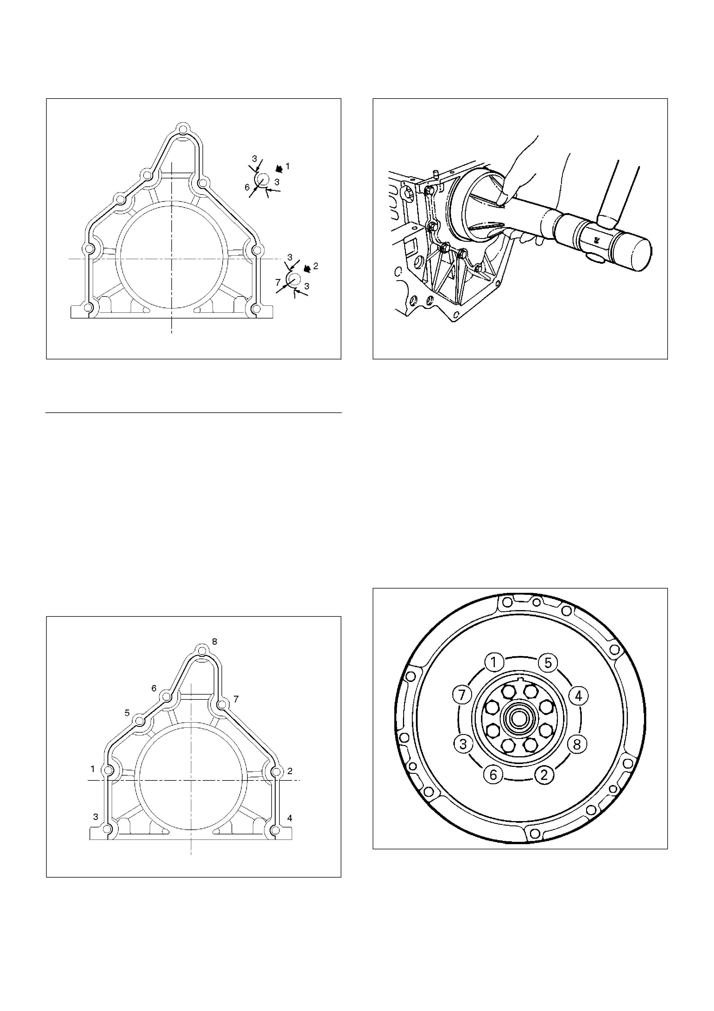
015RW002
EndOFC allout
• Apply engine oil to the oil seal lip.
• Align the cylinder block dowel pin holes with the
rear retainer dowel pins.
• Tighten the rear retainer fixing bolts. New bolts
should be used when installing rear retainer.
Torque: 18 N·m (1.8 Kg·m/13 lb ft)
NOTE: Be very careful not to disengage the oil seal
garter spring during installation of the rear retainer.
If the seal was removed from retainer for
replacement, apply engine oil to the oil seal lip
and install the oil seal using 5–8840–2286–0 oil
seal installer.
015RW001
015RS017
3. Flywheel (9)
1. Thoroughly clean and remove the oil from the
threads of crankshaft.
2. Remove the oil from the crankshaft and flywheel
mounting faces.
3. Mount the flywheel on the crankshaft and then
install the washer.
4. Hold the crankshaft to prevent from rotating then
install the bolts in the order shown to the
specified torque.
Torque: 54 N·m (5.5 Kg·m/40 lb ft)
NOTE: Do not reuse the bolt and do not apply oil or
thread lock to the bolt.
015RS018
Legend
(1) Around Bolt Holes
(2) Around Dowel Pin
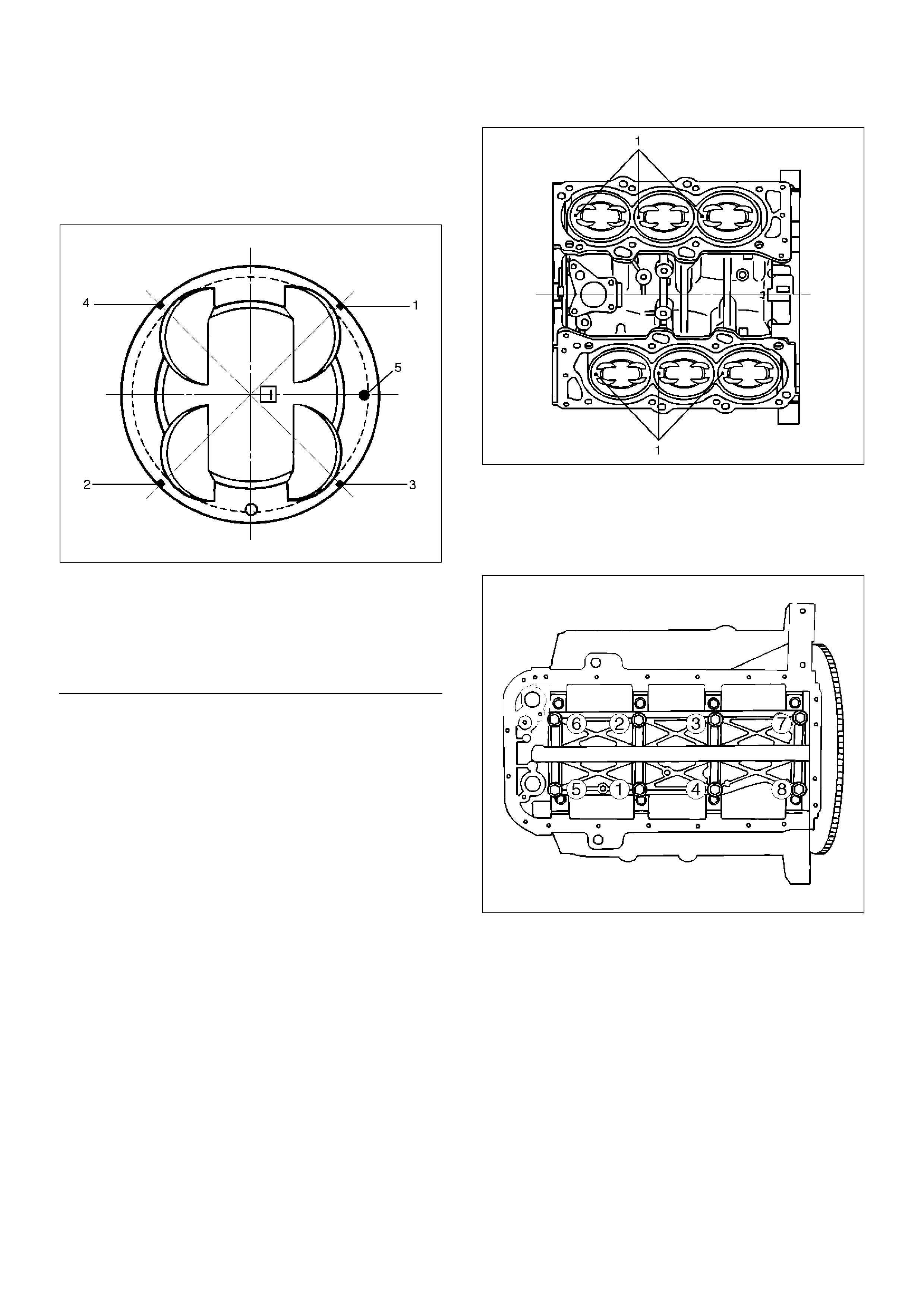
4. Piston and connecting rod assembly (8)
• Apply engine oil to the cylinder bores, the
connecting rod bearings and the crankshaft pins.
Check to see that the piston ring end gaps are
correctly positioned.
015RS019
EndOFC allout
• Insert the piston/connecting rod assemblies into
each cylinder with the piston ring compressor.
The front marks must be facing the front of the
engine.
• Match the numbered caps with the numbers on
the connecting rods. Align the punched marks on
the connecting rods and caps.
• Apply engine oil to the threads and seating faces
of the nuts.
• Tighten the nuts.
Torque: 54 N·m (5.5 Kg·m/40 lb ft)
After tightening the cap nuts, check to see that
the crankshaft rotates smoothly.
NOTE: Do not apply engine oil to the bearing back
faces.
015RS020
5. Install oil gallery (7) and tighten the bolts in 2 steps,
in the order shown.
1st step: 29 N·m (3.0 Kg·m/22 lb ft)
2nd step: 55°∼ 65°
051RS009
6. Cylinder block side bolts (6)
• Tighten all the bolts to the specified torque in the
order shown.
NOTE: Do not apply engine oil to the crank case side
bolts.
Torque: 39 N·m (4.0 Kg·m/29 lb ft)
Legend
(1) No.1 Compression Ring
(2) No.2 Compression Ring
(3) Oil Ring Side Rail Upper
(4) Oil Ring Side Rail Lower
(5) Piston Front Mark
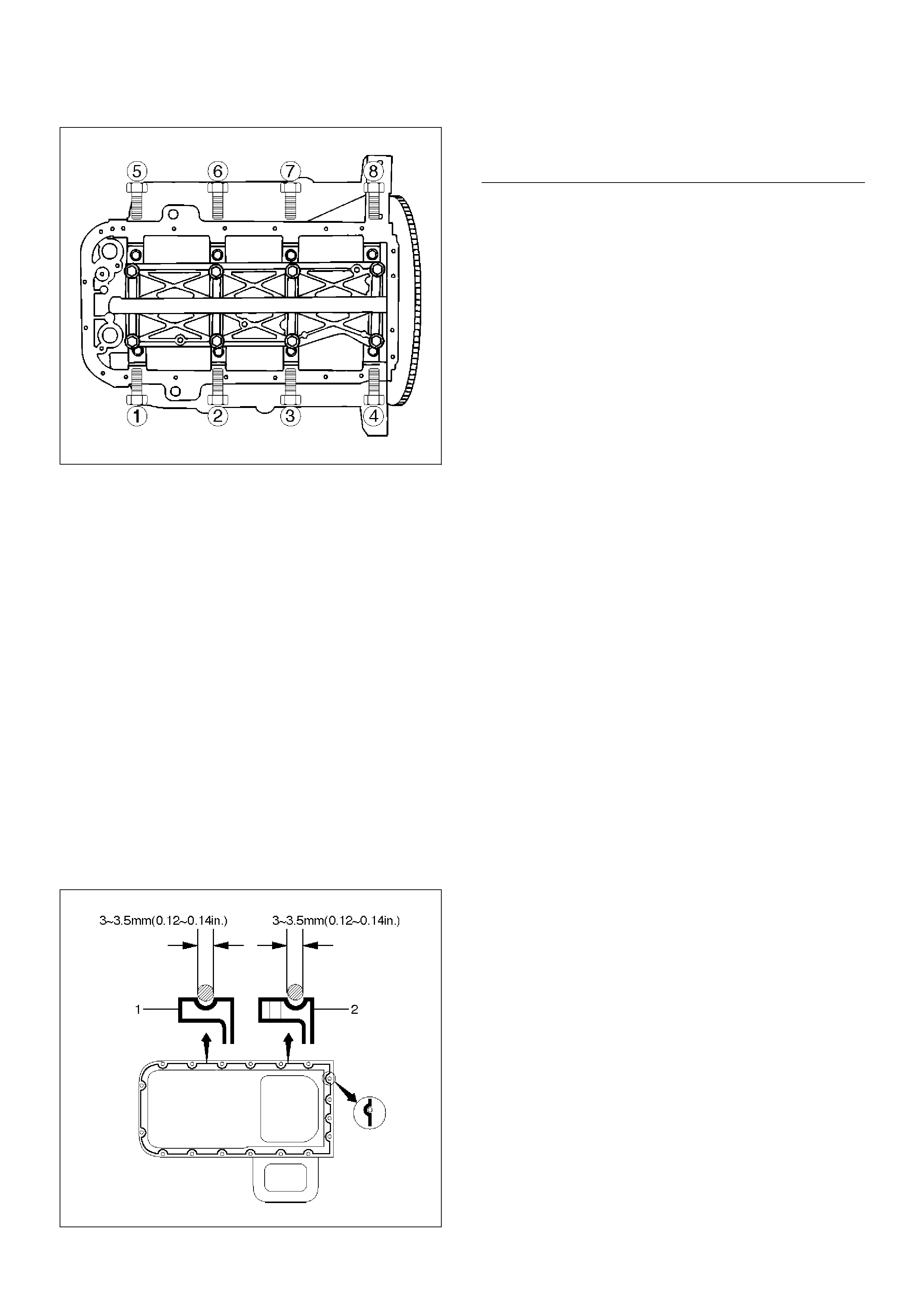
012RS001
7.Install oil pump assembly (5), refer to “Oil pump” in
this manual.
8.Install oil strainer and O-ring (4).
9.Install oil pipe and O-ring (3) and tighten the bolts.
Torque: 25 N·m (2.5 Kg·m/18 lb ft)
10.Install crankcase with oil pan (2).
1.Completely remove all residual sealant,
lubricant and moisture from the sealing
surfaces. The surfaces must be perfectly dry.
2.Apply a correct width bead of sealant (TB—
1207C or its equivalent) to the contact surfaces
of the oil pan. There must be no gaps in the
bead.
3.The crankcase assembly must be installed
within 5 minutes after sealant application to
prevent premature hardening of the sealant.
4.Tighten the bolts and nuts to the specified
torque.
Torque : 10 N·m (1.0 Kg·m/89 lb in)
013RW010
EndOFCallout
11.Install cylinder head assembly, refer to “Cylinder
head” in this manual.
Legend
(1) Portion Between Bolt Holes
(2) Bolt Hole Portion
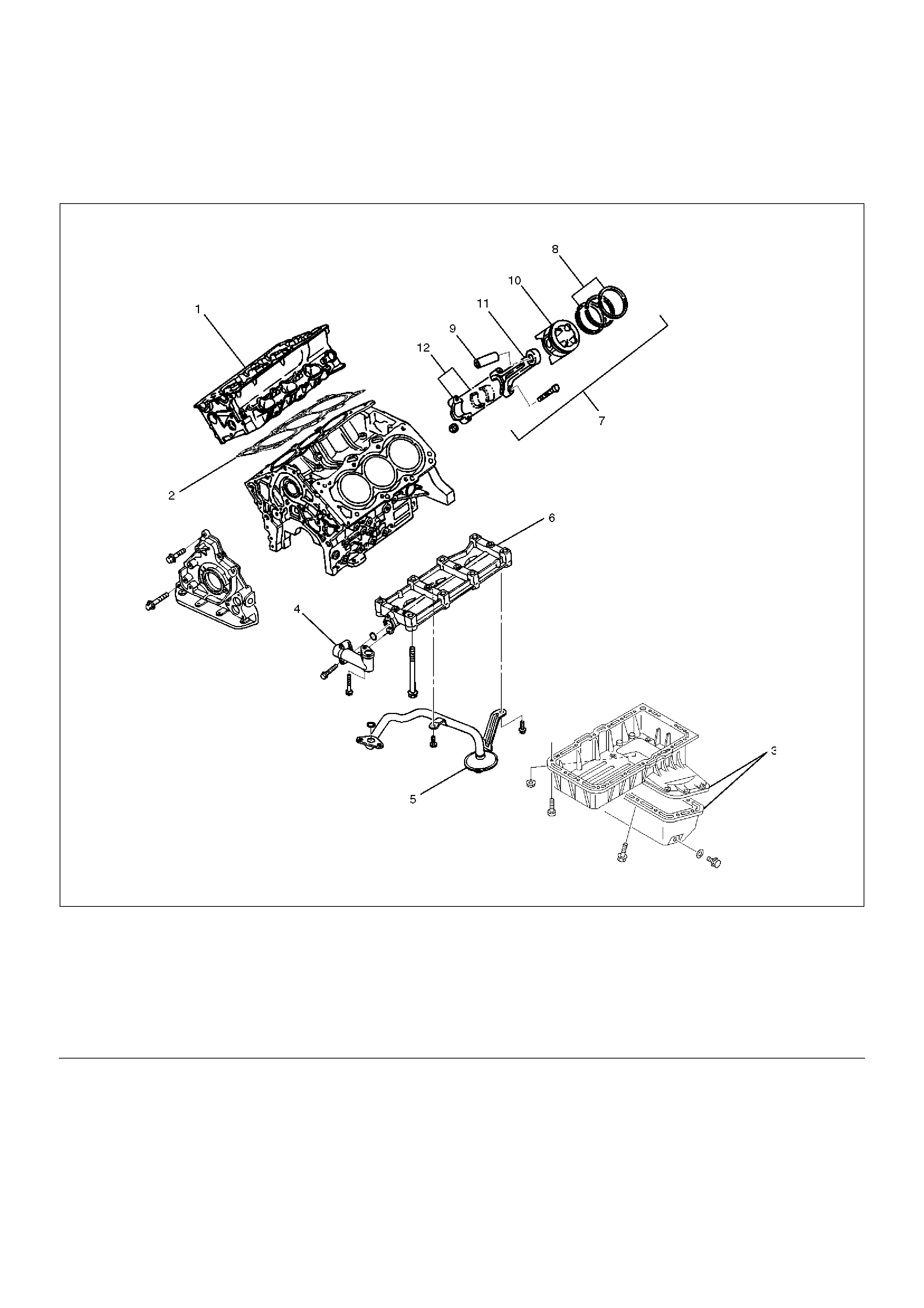
Piston and Connecting Rod
Piston, Connecting Rod and Associate Parts
015RW019
EndOFCallout
Disassembly
1.Remove cylinder head assembly (1). Refer to
“Cylinder Head Removal” in this manual.
2. Remove cylinder head gasket (2).
3.Remove crankcase with oil pan (3). Refer to “Oil Pan
and Crankcase” in this manual.
4. Remove oil pipe and O-ring (4).
5. Remove oil strainer and O-ring (5).
6. Remove oil gallery (6).
7. Remove connecting rod cap with connecting rod
lower bearing (12).
8. Remove piston and connecting rod assembly (7).
NOTE: Before removing piston and connecting rod
assembly, measure thrust clearance.
Legend
(1) Cylinder Head Assembly
(2) Cylinder Head Gasket
(3) Crankcase with Oil Pan
(4) Oil Pipe and O-Ring
(5) Oil Strainer and O-Ring
(6) Oil Gallery
(7) Piston and Connecting Rod Assembly
(8) Piston Ring
(9) Piston Pin
(10) Piston
(11) Connecting Rod
(12) Connecting Rod Cap
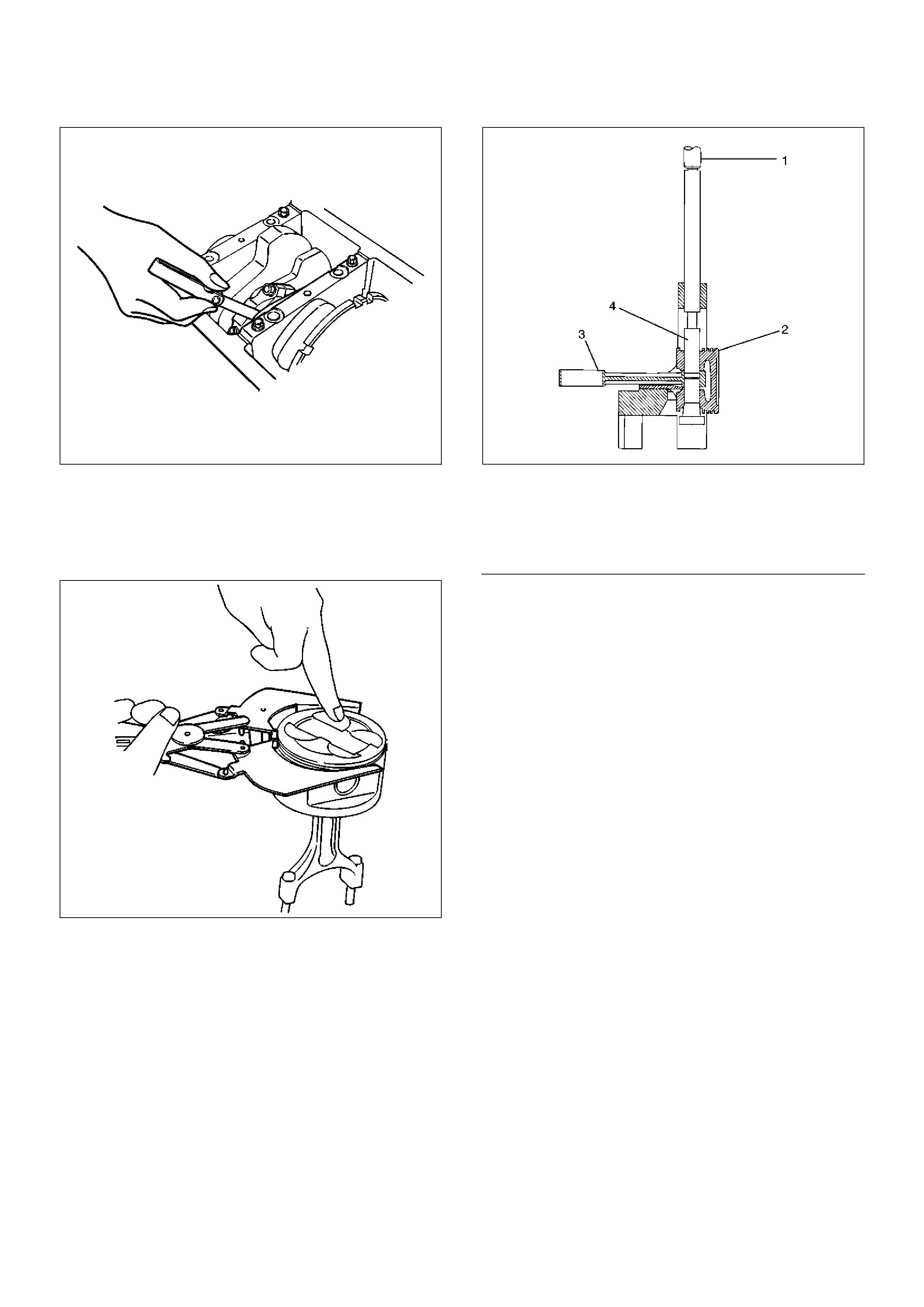
015RS031
• Remove any ridge or carbon build up from the top
end of the cylinder.
9. Remove the piston rings (8) with a piston ring
expander. Arrange the removed piston rings in the
cylinder number order.
015RS022
10. Remove the piston pin (9) using 5–8840–0551–0
piston pin service set and piston support with a
press.
NOTE: Keep the parts removed from each cylinder
separate. All parts must be reinstalled in their original
positions. Heating the connecting rod will permit easy
removal of the piston pin.
015RX001
EndOFC allout
11. Piston (10)
12. Connecting rod (11)
Inspection and Repair
Pistons (10)
Carefully clean away all the carbon adhering to the
piston head and the piston ring grooves.
NOTE: Never use a wire brush to clean the pistons.
Damage will result. Visually check each piston for
cracking, scoring, and other signs of excessive wear. If
any of the above conditions are found, the piston must
be replaced.
Piston Diameter
1. Measure the piston outside diameter with
micrometer at the piston grading position and a right
angle to the piston pin.
Piston grading position (from piston head)
Piston grading position : 43.0 mm (1.6929 in)
Legend
(1) Press Ram
(2) Piston
(3) Connecting Rod
(4) Piston Pin
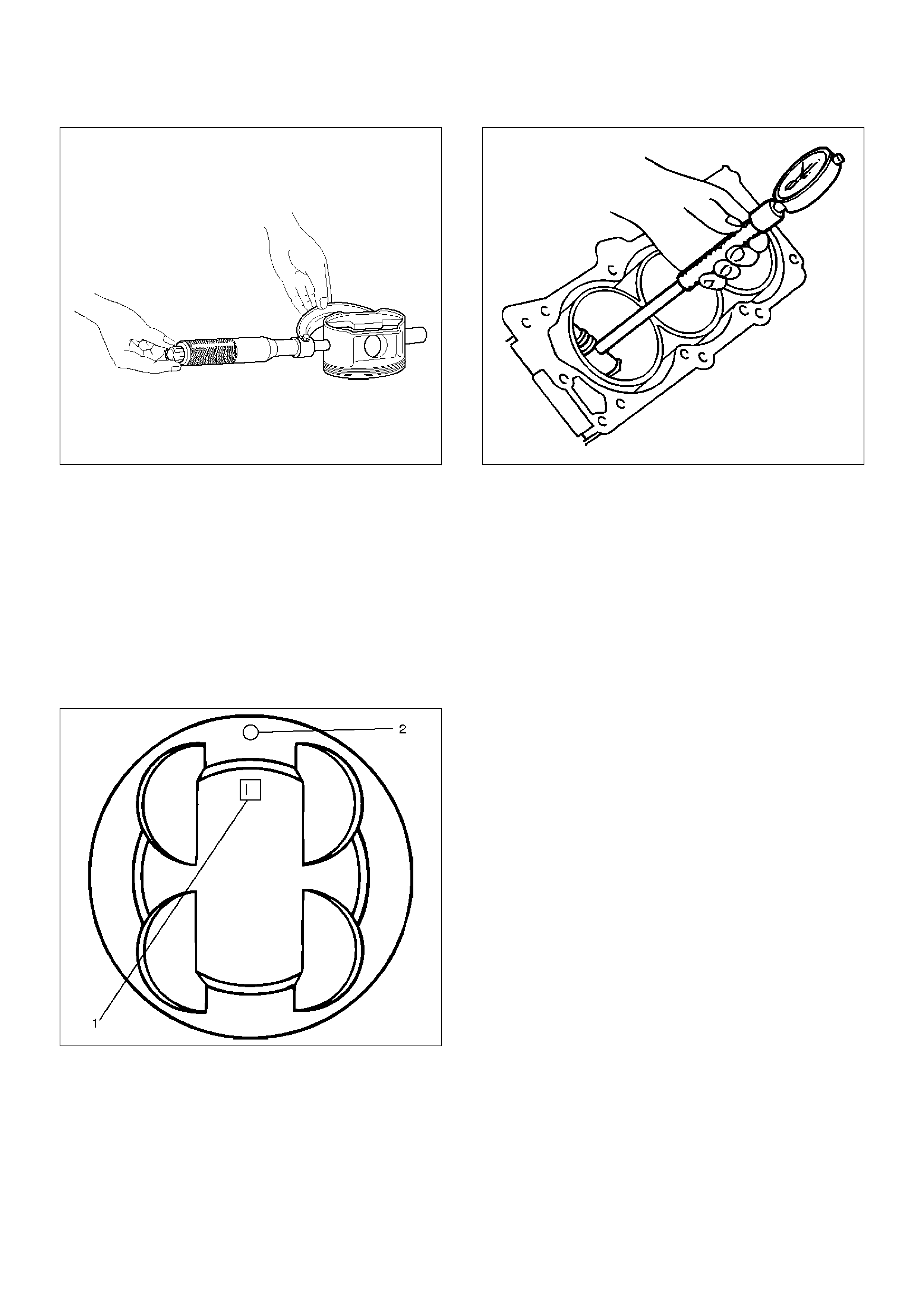
015RV014
The size mark (1) for piston outside diameter is
represented as shown in illustration below.
Outside Diameter
Size Mark A : 93.360 mm–93.370 mm
(3.6756 in–3.6760 in)
Size Mark B : 93.371 mm–93.380 mm
(3.6760 in–3.6764 in)
Size Mark C : 93.381 mm–93.390 mm
(3.6764 in–3.6768 in)
015RS025
Measure the cylinder bore inside diameter (refer to
“Cylinder Block” in this manual).
012RS002
Piston Rings (8)
Any worn or damaged part discovered during engine
overhaul must be replaced with a new one.
1. Ring end gap measurement
• Insert the piston ring into the bore.
• Push the ring by the piston, at a right angle to the
wall, into the point at which the cylinder bore
diameter is the smallest.
• Measure the ring end gap.
Compression Ring
1st ring
Standard: 0.300 mm–0.400 mm
(0.0118 in–0.0157 in)
Limit: 1.0 mm (0.0394 in)
2nd ring
Standard: 0.450 mm–0.600 mm
(0.0177 in–0.0236 in)
Limit: 1.2 mm (0.0472 in)
Oil ring
Standard: 0.150 mm–0.450 mm
(0.0059 in–0.0177 in)
Limit: 1.05 mm (0.0413 in)
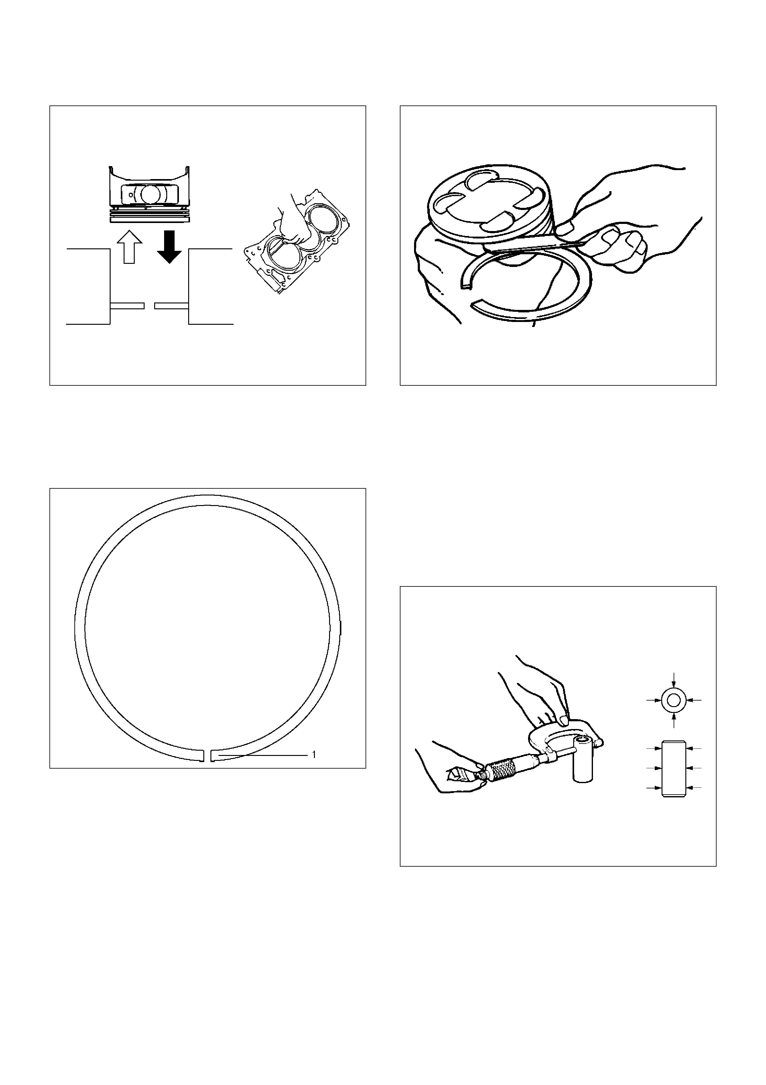
015RS026
• Positioning mark (1) is painted as shown in the
illustration.
Marked T : No.1 Compression ring
Marked T2 : No.2 Compression ring
015RS027
2. Measure the clearance between the piston ring
groove and the piston ring with a feeler gauge. If the
piston ring groove / piston ring clearance exceeds
the specified limit, the piston must be replaced.
Compression Ring Clearance
Standard : 0.016 mm–0.038 mm
(0.0006 in.–0.0015 in)
Limit : 0.15mm (0.0059 in)
015RS028
Piston Pin (9)
NOTE: Do not reuse the old piston pin.
1. Use a micrometer to measure the new piston pin
outside diameter in both directions at three different
positions.
2. Measure the inside diameter of the connecting rod
small end. If the fitting interference between the
small end and pin does not conform to the specified
value, the connecting rod must be replaced.
Standard : 0.023 mm–0.038 mm (0.0009 in–0.0015
in)
015RS029
3. Insert the new pin into the piston and rotate it. If the
pin rotates smoothly with no backlash, the clearance
is normal. If there is backlash or roughness,
measure the clearance. If the clearance exceeds
the specified limit, the piston must be replaced.
Clearance
Standard : 0.010 mm–0.017 mm
(0.0004 in.–0.0007 in)
Limit : 0.040 mm (0.0016 in)
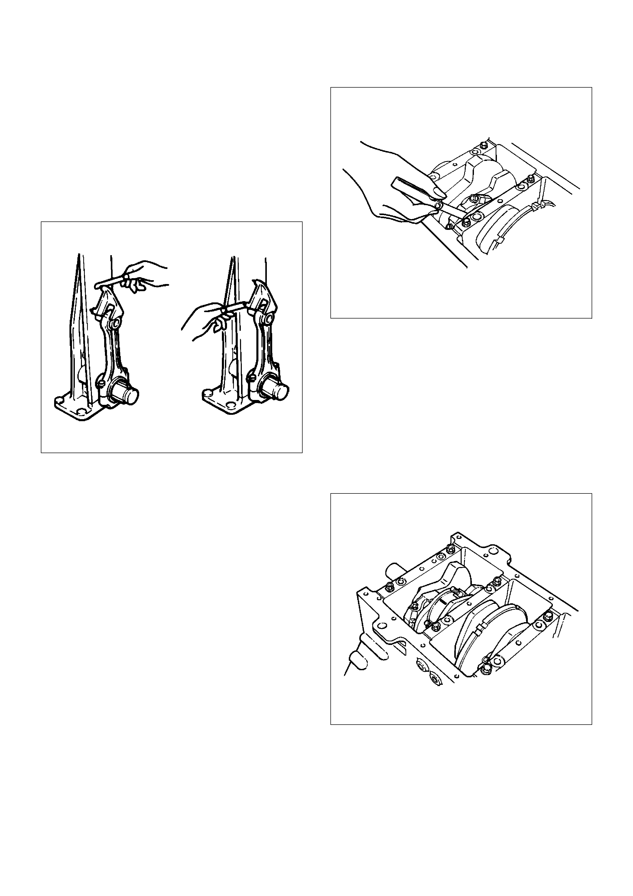
Connecting Rods (11)
1. Check the connecting rod alignment If either the
bend or the twist exceeds the specified limit, the
connecting rod must be replaced.
Bend per 100 mm (3.937 in)
Limit: 0.15 (0.0059)
Twist per 100 mm (3.937 in)
Limit: 0.20 (0.0078)
015RS030
2. Measure the connecting rod thrust clearance. Use a
feeler gauge to measure the thrust clearance at the
large end of the connecting rod If the clearance
exceeds the specified limit, the connecting rod must
be replaced.
Standard : 0.16 mm–0.35 mm
(0.0063 in.–0.0138 in)
Limit : 0.40 mm (0.0157 in)
015RS031
3. Measure the oil clearance between the connecting
rod and the crankshaft.
1. Remove the connecting rod cap nuts and the
rod caps (12).
Arrange the removed rod caps in the cylinder
number order.
2. Clean the rod bearings and the crankshaft pins.
3. Carefully check the rod bearings. If even one
bearing is found to be damaged or badly worn,
the entire bearing assembly must be replaced
as a set. Reinstall the bearings in their original
positions. Apply plastigage to the crank pin.
015RS032
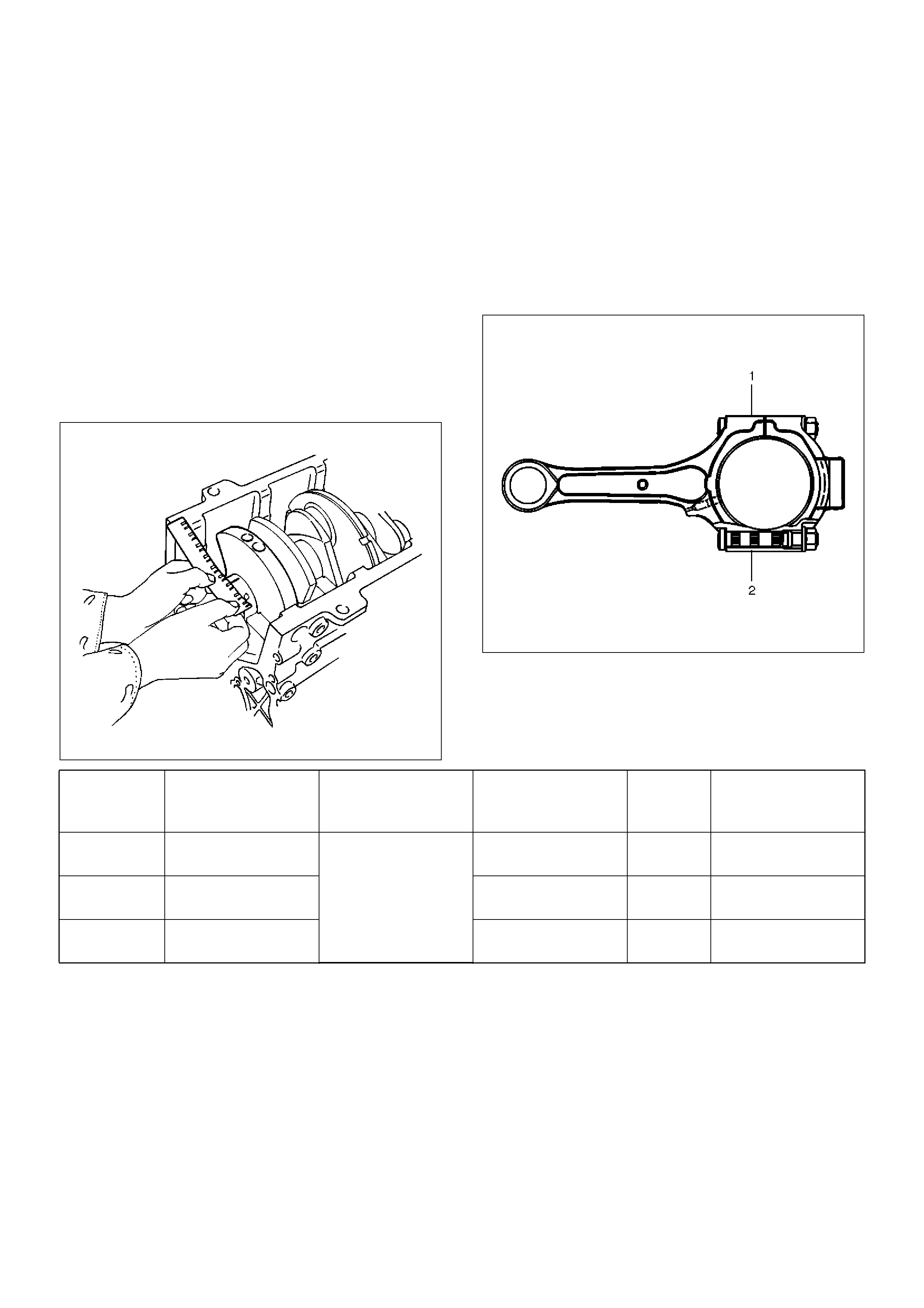
4. Reinstall the rod caps (12) to their original
positions.
Tighten the rod cap nuts.
Torque: 54 N·m (5.5 Kg·m/40 lb ft)
NOTE: Do not allow the crankshaft to rotate.
5. Remove the rod caps.
6. Measure the width of the plastigage and
determine the oil clearance. If the oil clearance
exceeds the limit, replace the rod bearing as a
set.
Standard : 0.019 mm–0.043 mm
(0.0007 in–0.0017 in)
Limit : 0.08 mm (0.003 in)
015RS008
7. Clean the plastigage from the bearings and the
crankshaft pins.
Con–rod Bearing Selection
Select and install the new connecting rod bearings,
paying close attention to the connecting rod big end
diameter size mark (1).
NOTE: Take care not to confuse the alignment mark (2)
and the size mark (1) during the installation procedure.
015RS034
Reassembly
1. Install connecting rod
2. Install piston
3. Install piston pin
• Apply a thin coat of engine oil to the piston pin.
Try to insert the piston pin into the piston pin hole
with normal finger pressure.
NOTE: When changing piston / connecting rod
combinations, do not change the piston / piston pin
combination and do not reuse the old piston pin.
1 Size Mark Big end Bore
Diameter
Crankshaft Pin
Diameter
Connecting Rod
Bearing Thickness
(Reference)
Color of
Size Mark
Oil Clearance
(Reference)
A56.994-57.000
(2.2439-2.2441)
53.922-53.937
(2.1229-2.1235)
1.512-1.516
(0.0595-0.0597) Yellow 0.025-0.054
(0.0010-0.0021)
B56.988-56.994
(2.2436-2.2439)
1.508-1.512
(0.0594-0.0595) Green 0.027-0.056
(0.0011-0.0022)
C56.982-56.988
(2.2434-2.2436)
1.504-1.508
(0.0592-0.0594) Pink 0.029-0.058
(0.0011-0.0023)
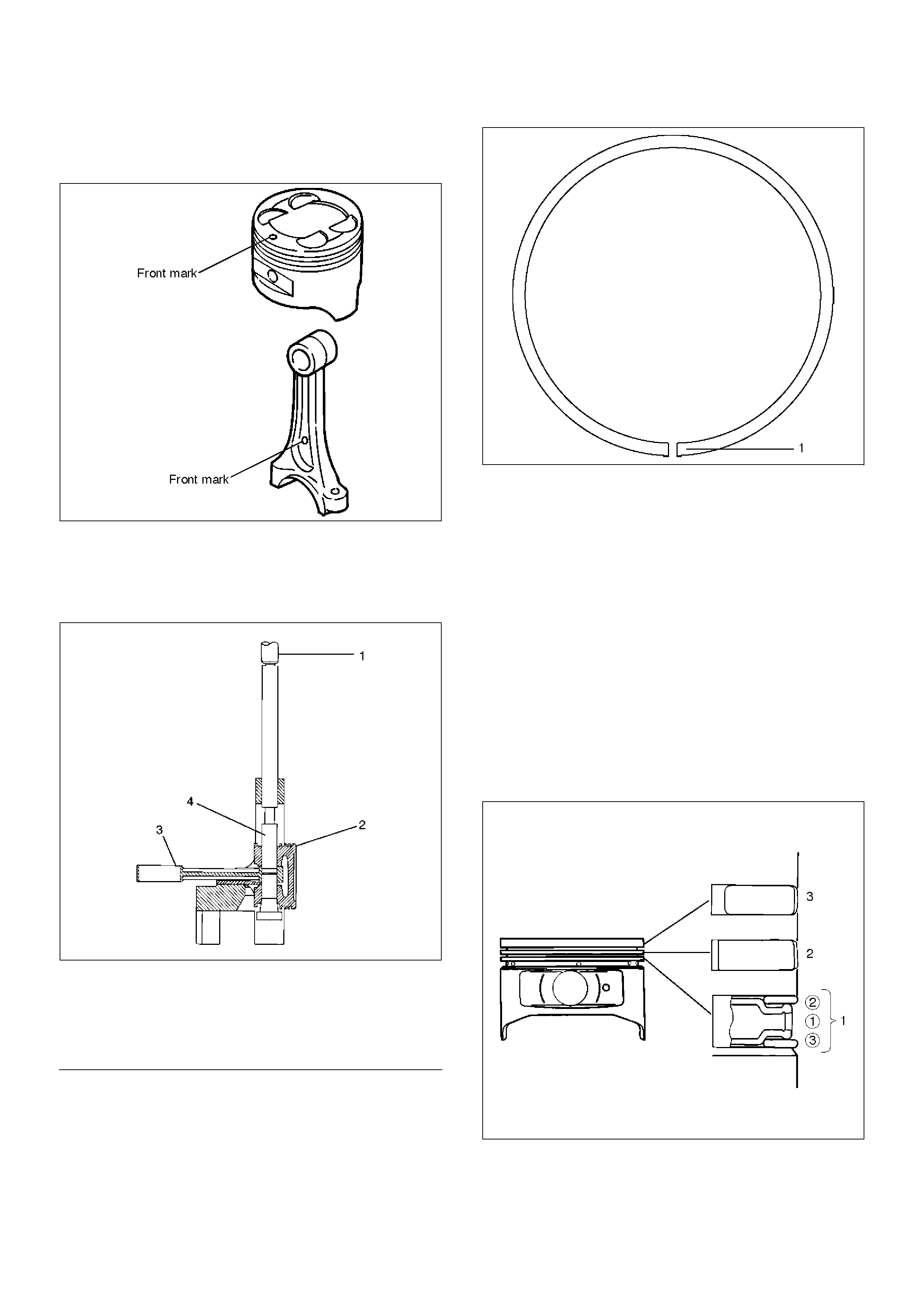
• Attach the piston to the connecting rod with the
piston front mark and the connecting rod front
mark on the same side.
015RS036
• With 5–8840–0551–0 Piston pin service set and a
press, press fit the piston pin.
NOTE: Heat the connecting rod small end to a suitable
temperature to ensure smooth installation.
015RX001
EndOFC allout
4. Install piston ring with the piston ring expander.
The compression ring must be set with the T mark
(1) facing up.
Marked T : No.1 Compression ring
Marked T2 : No.2 Compression ring
015RS027
• Install piston rings in the following sequence.
1Oil ring
1 Expander ring
2 Upper side rail
3 Lower side rail
2 2nd compression ring
3 1st compression ring
• The compression rings must be set with the T or
T2 mark facing up.
Marked T : No.1 Compression ring
Marked T2 : No.2 Compression ring
• After installation, apply engine oil to the entire
circumference of the piston rings. Check to see
that all the rings rotate smoothly.
015RS038
5. Install piston and connecting rod assembly.
• Insert the bearings into the connecting rods and
caps. Apply new engine oil to the bearing faces
and nuts.
Legend
(1) Press Ram
(2) Piston
(3) Connecting Rod
(4) Piston Pin

•Tighten the connecting rod cap nuts
Torque : 54 N·m (5.5 Kg·m/40 lb ft)
NOTE: Do not apply engine oil to the bearing back
faces.
6.Oil gallery, refer to “Crankshaft and main bearing” in
this manual.
7.Oil strainer and O-ring.
8.Oil pipe and O-ring.
9.Install crankcase with oil pan, refer to “Oil pan and
Crankcase” in this manual.
10. Install cylinder head gasket.
11. Install Cylinder head assembly.
•Refer to “Cylinder head” in this manual.
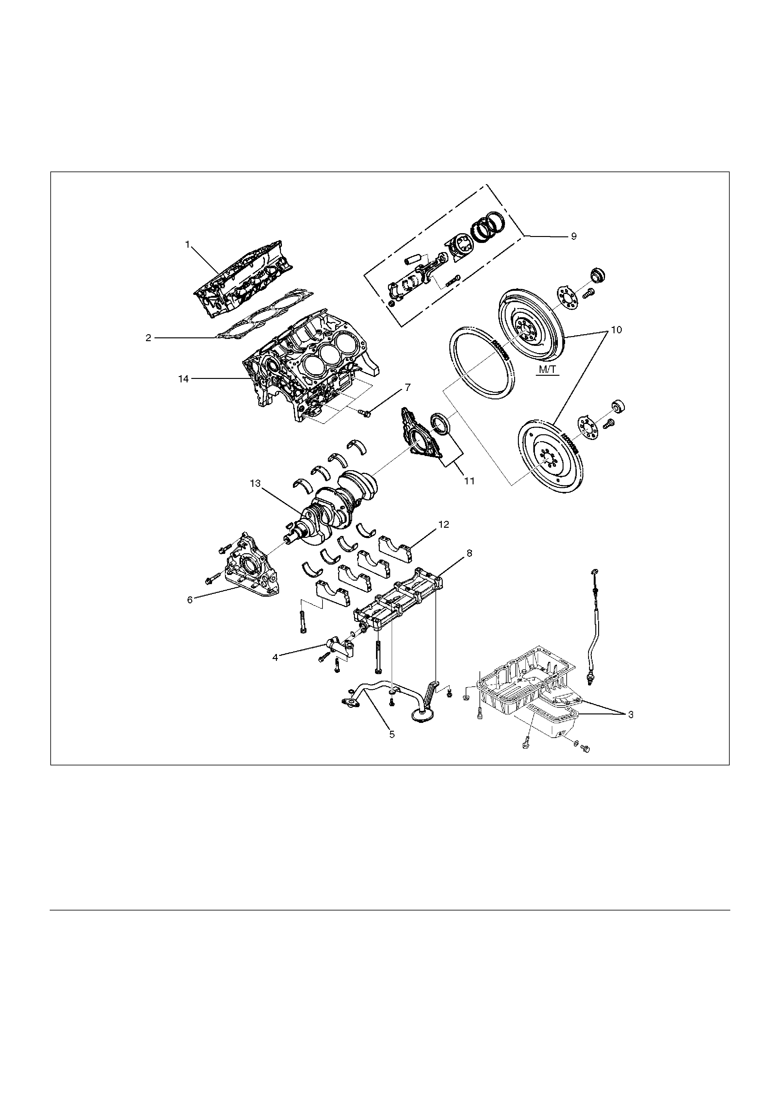
Cylinder Block
Cylinder Block and Associated Parts
012RW010
EndOFCallout
Disassembly
1. Remove cylinder head assembly.
2. Remove cylinder head gasket.
3. Remove crankcase with oil pan.
4. Remove oil pipe and O-ring.
5. Remove oil strainer and O-ring.
6. Remove oil pump assembly.
7. Remove crankcase side bolts.
8. Remove oil gallery.
9. Remove piston and connecting rod assembly.
10. Remove flywheel.
11. Remove rear oil seal retainer assembly.
Legend
(1) Cylinder Head Assembly
(2) Cylinder Head Gasket
(3) Crankcase with Oil Pan
(4) Oil Pipe and O-Ring
(5) Oil Strainer and O-Ring
(6) Oil Pump Assembly
(7) Cylinder Block Side Bolts
(8) Oil Gallery
(9) Piston and Connecting Rod Assembly
(10) Flywheel
(11) Rear Oil Seal Retainer Assembly
(12) Main Bearing Cap
(13) Crankshaft
(14) Cylinder Block
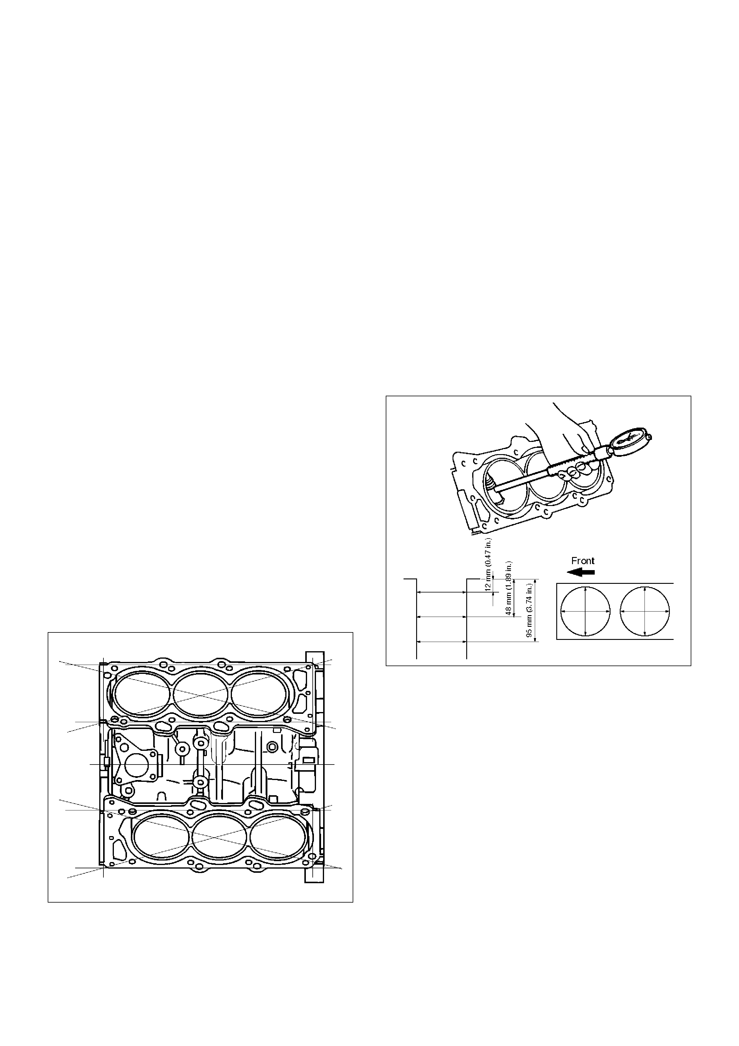
12.Remove main bearing cap.
13.Remove crankshaft.
14.Remove cylinder block.
Inspection and Repair
1.Remove the cylinder head gasket and any other
material adhering to the upper surface of the
cylinder block. Be very careful not to allow any
material to accidentally drop into the cylinder block.
Be very careful not to scratch the cylinder block.
2.Carefully remove the oil pump, rear oil seal retainer,
and crankcase assembly installation surface seal.
3.Wipe the cylinder block clean.
4.Visually inspect the cylinder block. If necessary, use
a flaw detector to perform a dye penetrate and
hydraulic (or air pressure) test. If cracking or other
damage is discovered, the cylinder block must
either be repaired or replaced.
Flatness
1.Using a straight–edge and feeler gauge, check that
the upper surface of the cylinder block is not
warped.
CAUTION: Be very careful not to allow any material
to accidentally drop into the upper surface of the
cylinder block. Be very careful not to scratch the
upper surface of the cylinder block.
2.The cylinder block must be reground or replaced if
the warpage exceeds the limit.
Warpage
Limit : 0.15 mm (0.0059 in)
Maximum repairable limit: 0.15 mm (0.0059 in)
012RS004
Cylinder Bore
Use a cylinder gauge to measure the cylinder bore
diameter in both the axial and thrust directions. Each
measurement should be made at six points.
CAUTION: Be very careful not to allow any material
to accidentally drop into the upper surface of the
cylinder block. Be very careful not to scratch the
upper surface of the cylinder block.
Cylinder Bore Inside Diameter
Limit : 93.530 (3.6823)
If the measurement exceed the specified limit, the
cylinder block must be replaced.
Diameter
Grade A : 93.400 mm–93.410 mm
(3.6772 in–3.6776 in)
Grade B : 93.411 mm–93.420 mm
(3.6776 in–3.6779 in)
Grade C : 93.421 mm–93.430 mm
(3.6780 in–3.6783 in)
012RS005
NOTE: For information on piston diameter, please refer
to the section "Inspection of the Piston and Connecting
Rod Assembly" in this manual.
• The "Grade" mark (1) is stamped at the position
illustrated.
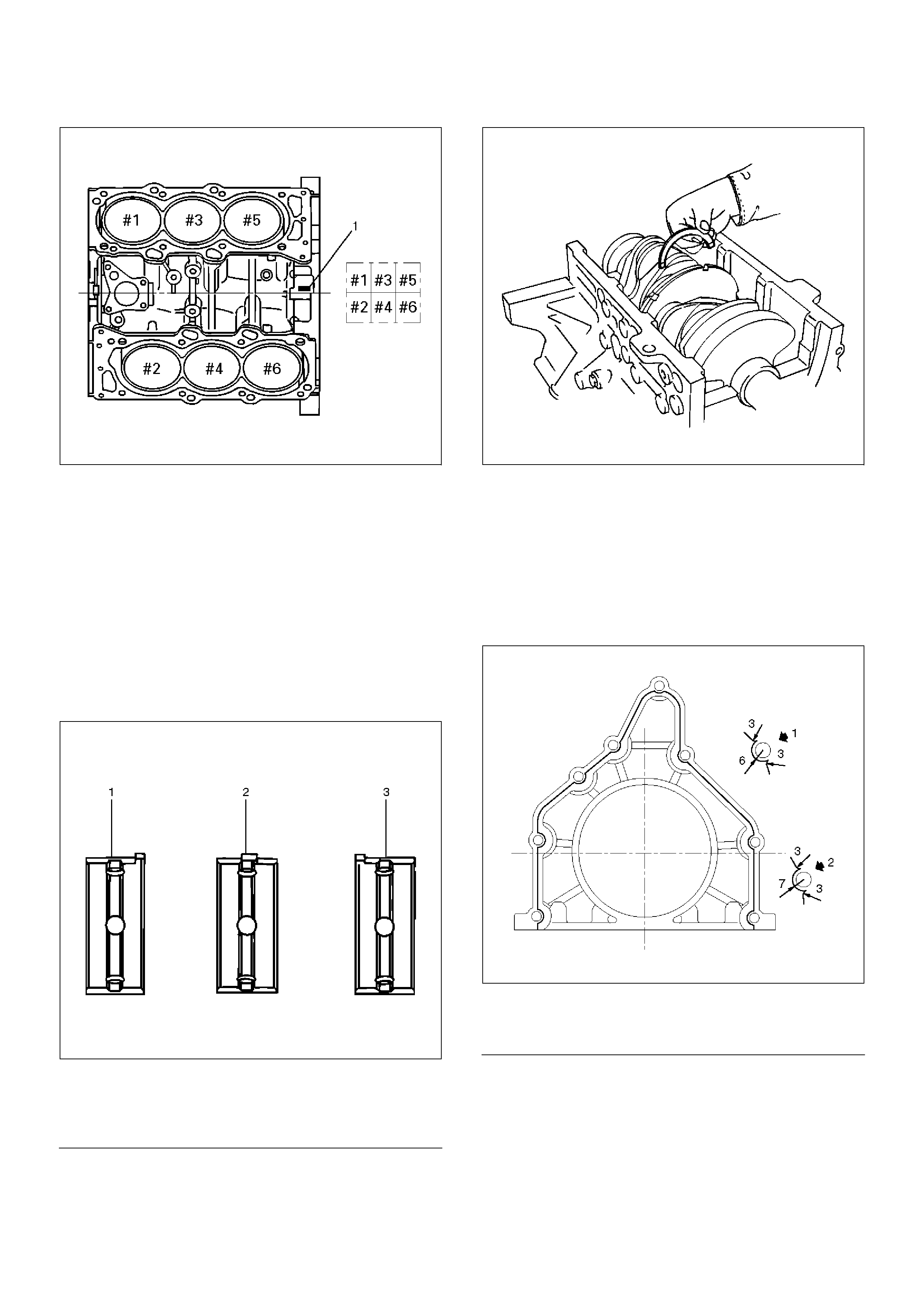
012RS006
Reassembly
1. Install cylinder block.
2. Install crankshaft.
• Install the main bearings to the cylinder block and
the main bearing caps.
• Be sure that they are positioned correctly.
• Apply new engine oil to the upper and lower main
bearing faces.
NOTE: Do not apply engine oil to the bearing back
faces.
015RS012
EndOFC allout
• Carefully mount the crankshaft.
• Apply engine oil to the thrust washer.
• Assemble the thrust washer to the No. 3 bearing
journal. The oil grooves must face the crankshaft.
015RS013
3. Install rear oil seal retainer.
• Remove oil on cylinder block and retainer fitting
surface.
• Apply sealant (TB1207B or equivalent) to retainer
fitting surface as shown in illustration.
• The oil seal retainer must be installed within 5
minutes after sealant application before the
sealant hardens.
015RW002
EndOFCallout
• Apply engine oil to oil seal lip and align a dowel
pin hole in the cylinder block with that in the
retainer.
• Tighten retainer fixing bolts to the specified
torque.
Torque: 25 N·m (2.5 Kg·m/18.4 lb ft)
Legend
(1) Number 1 and 4 main bearing upper and lower.
(2) Number 2 and 3 main bearing upper.
(3) Number 2 and 3 main bearing lower.
Legend
(1) Around Bolt Holes
(2) Around Dowel Pin
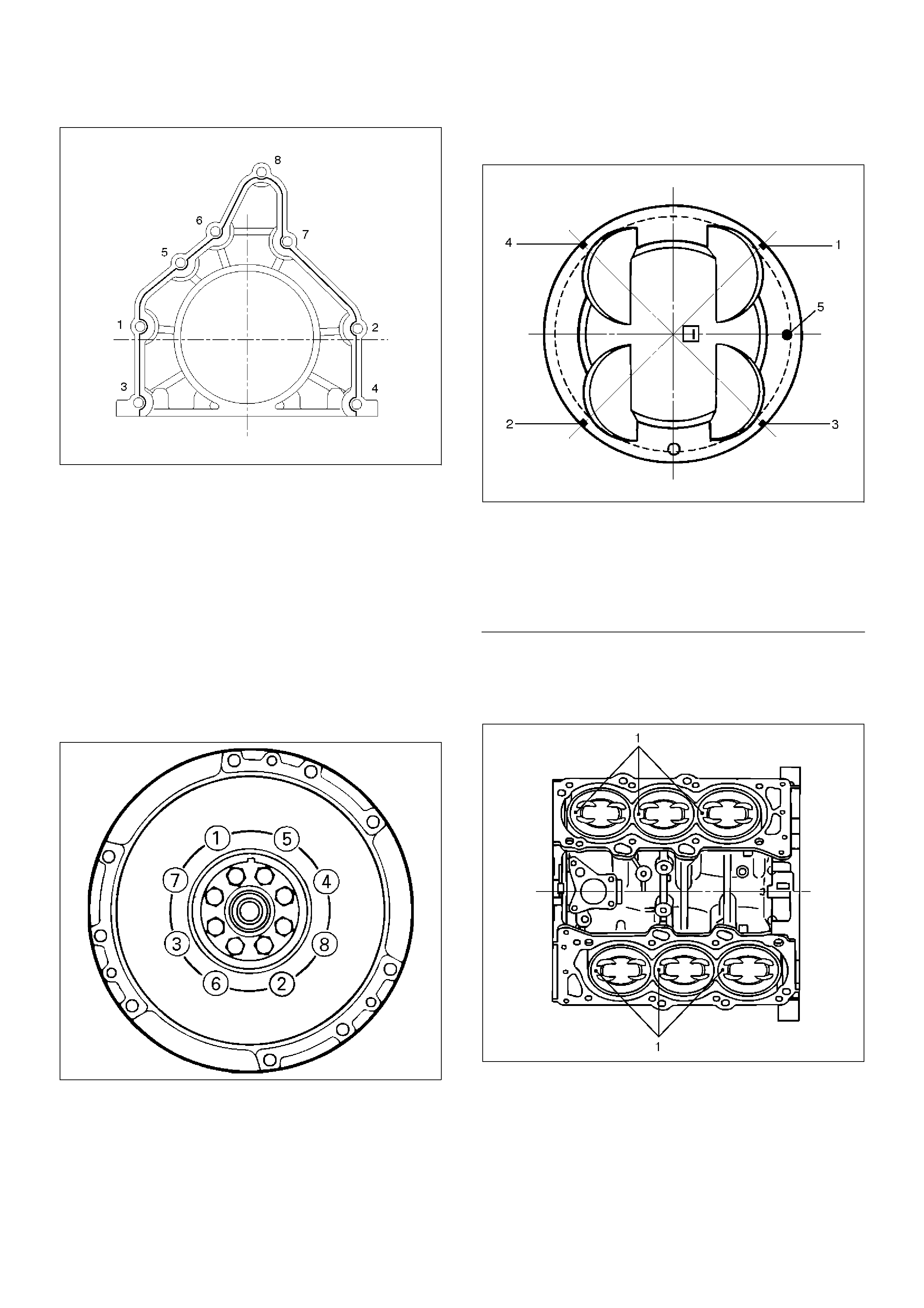
015RW001
4. Install flywheel
1. Thoroughly clean and remove the oil from the
threads of crankshaft.
2. Remove the oil from the crankshaft and flywheel
mounting faces.
3. Mount the flywheel on the crankshaft and then
install the washer.
4. Holding the crankshaft stationary, tighten the
flywheel bolts in the order shown.
Torque: 54 N·m (5.5 Kg·m/40 lb ft)
NOTE: Do not reuse the bolts and do not apply oil or
thread lock to the bolts.
015RS018
5. Install piston and connecting rod assembly.
• Apply engine oil to the cylinder bores, the
connecting rod bearings and the crankshaft pins.
NOTE: Do not apply engine oil to the bearing back
faces.
• Check to see that the piston ring end gaps are
correctly positioned.
015RS019
EndOFCallout
• Insert the piston/connecting rod assemblies into
each cylinder with the piston ring compressor.
• The front marks (1) must be facing the front of the
engine.
015RS020
6. Install oil gallery and tighten the bolts in 2 steps in
the order shown.
1st step : 29 N·m (3.0 Kg·m/22 lb ft)
2nd step : 55°∼ 65°
Legend
(1) No.1 Compression Ring
(2) No.2 Compression Ring
(3) Oil Ring Side Rail Upper
(4) Oil Ring Side Rail Lower
(5) Piston Front Mark
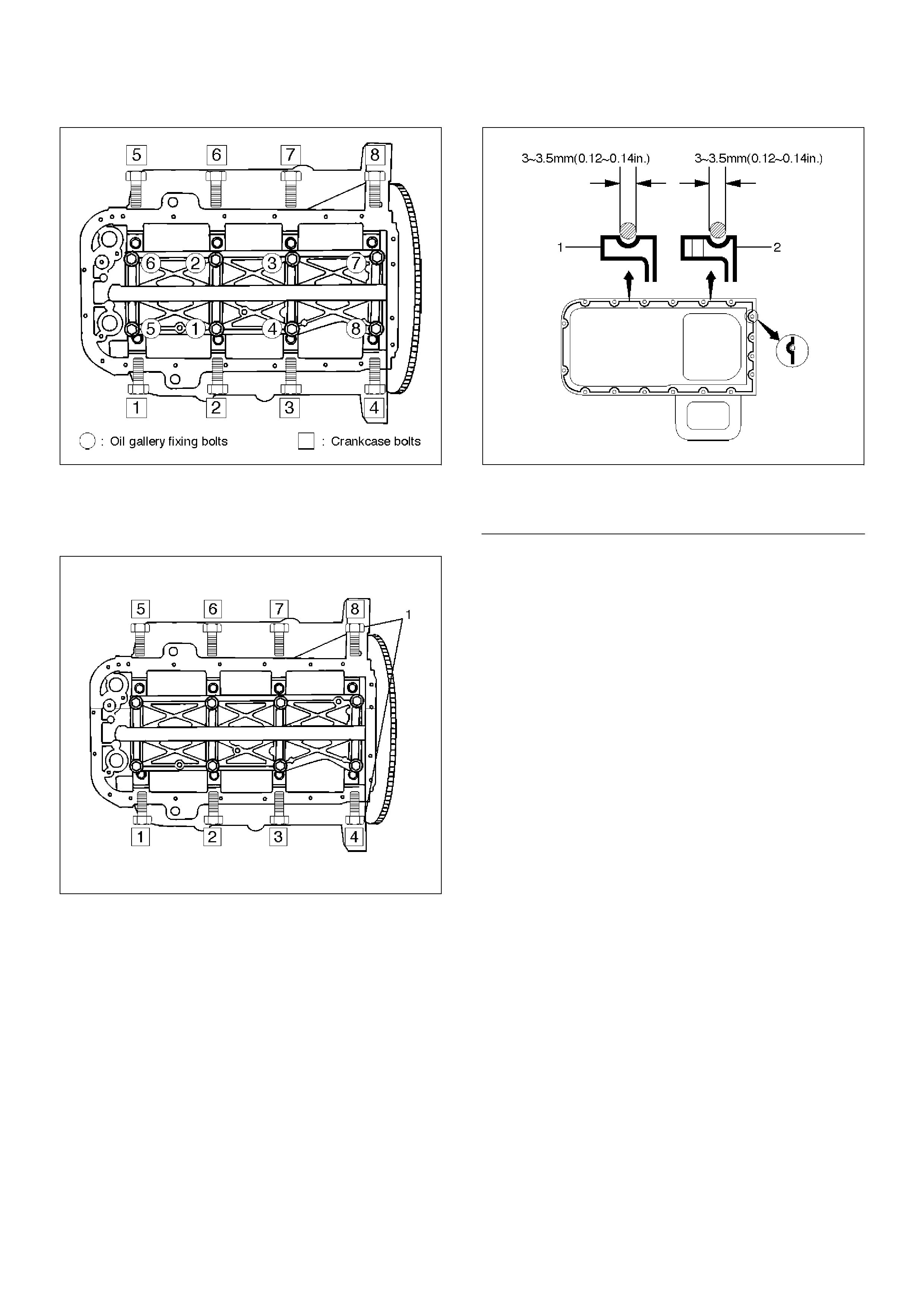
012RS007
7.Install cylinder block side bolts (1) and tighten
crankcase bolts in sequence shown in the
illustration.
Torque : 39 N·m (4.0 Kg·m/29 lb ft)
012RW005
8.Install oil pump assembly. Refer to “Oil Pump” in this
manual.
9.Install oil strainer and O-ring.
10.Install oil pipe and O-ring.
11.Install crankcase with oil pan.
1.Completely remove all residual sealant,
lubricant and moisture from the sealing
surfaces. The surfaces must be perfectly dry.
2.Apply a correct width bead of sealant (TB–
1207C or its equivalent) to the contact surfaces
of the crankcase. There must be no gaps in the
bead.
3.The oil pan must be installed within 5 minutes
after sealant application to prevent premature
hardening of sealant.
4.Tighten the bolts and nuts to the specified
torque.
Torque : 10 N·m (1.0 Kg·m/89 lb in)
013RW010
EndOFCallout
12.Install cylinder head gasket.
13.Install cylinder head assembly. Refer to “Cylinder
Head” in this manual.
Legend
(1) Portion Between Both Holes
(2) Bolt Hole Portions
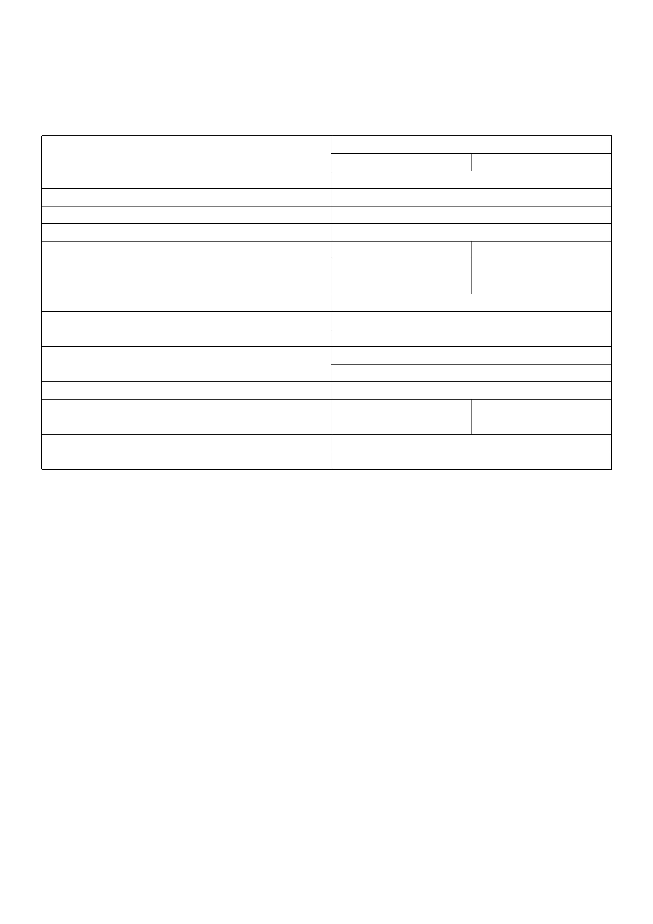
Main Data and Specification
General Specification
Item Specifications
6VD1 6VE1
Engine type, number of cylinders and arrangement Water cooled, four cycle V6
Form of combustion chamber Pent roof type
Valve mechanism 4-Cams, 4-Valves, DOHC Gear & Belt Drive
Cylinder liner type Casted in cylinder drive
Total piston displacement 3165 cc 3494 cc
Cylinder bore x stroke 93.4mm x 77.0mm 93.4mm x 85.0mm
(3.6772 in x 3.0315 in) (3.6772 in x 3.3465 in)
Compression ratio 9.1 : 1
Compression pressure at 300rpm 14.0 Kg/cm2
Engine idling speed rpm Non adjustable (750)
Valve clearance Intake: 0.28 mm (0.11 in)
Exhaust: 0.30mm (0.12in)
Oil capacity 5.3 liters
Ignition timing Non adjustable Non adjustable
16° BTDC at idle rpm) (20° BTDC at idle rpm)
Spark plug K16PR-P11, PK16PR11, RC10PYP4
Plug gap 1.0 mm–1.1 mm(0.0394 in – 0.0433 in)
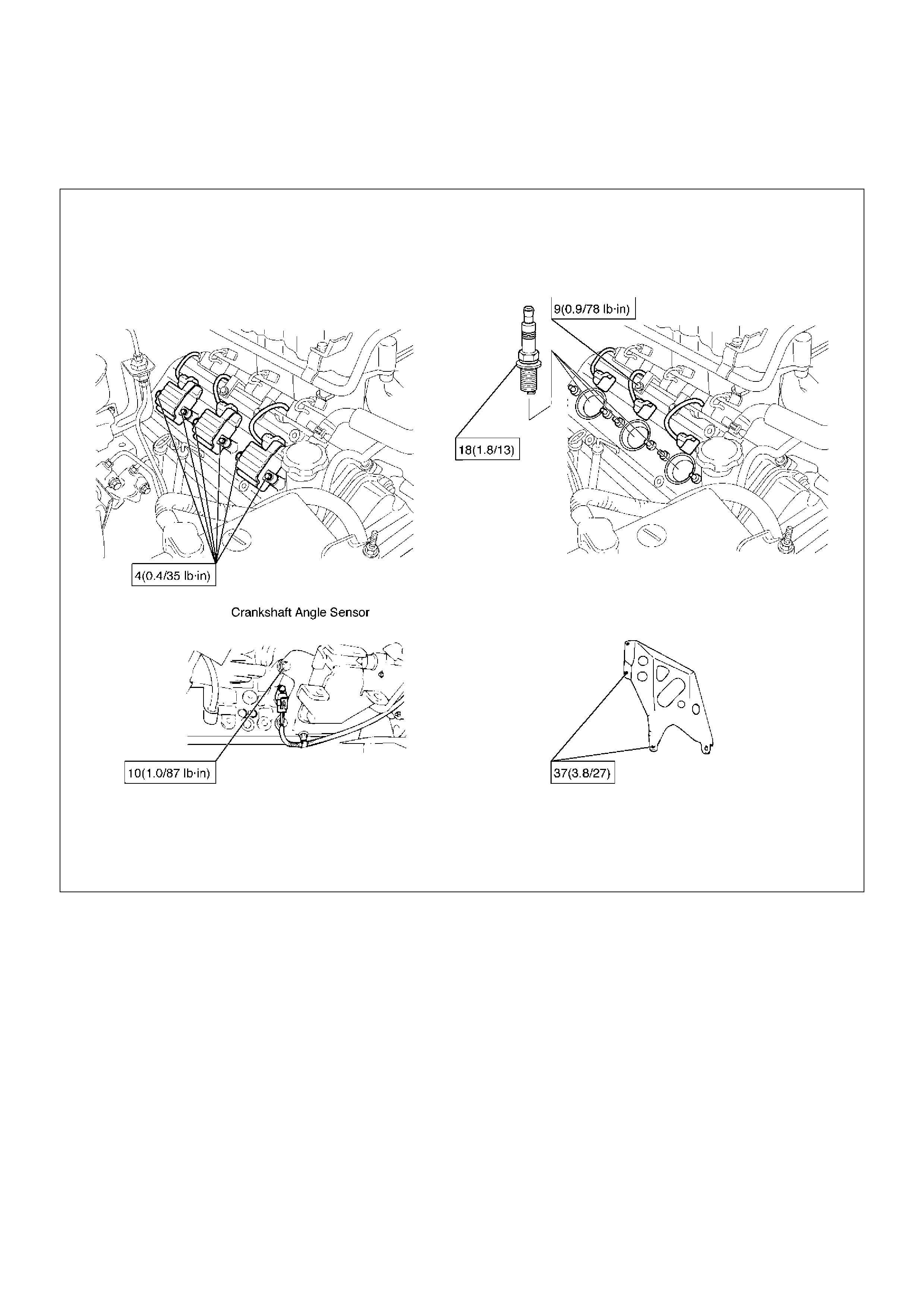
Torque Specifications
Ignition coil, Spark plug, Crankshaft angle sensor and Under cover
N·m (Kg·m/lbft)
E06RW038
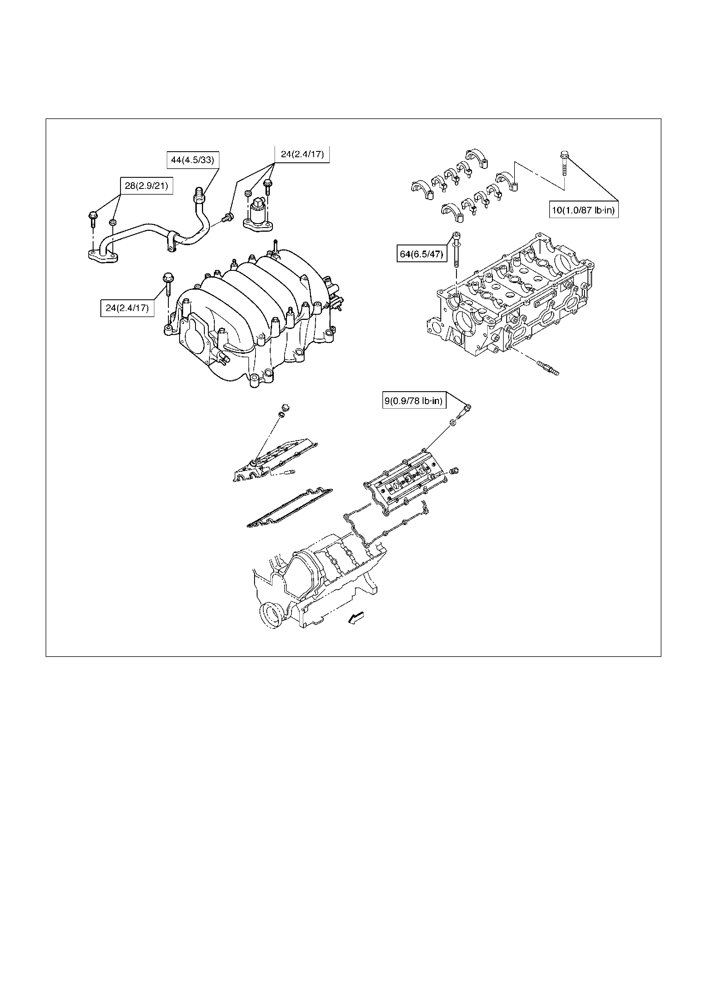
Cylinder head cover, Cylinder head, Camshaft bracket, Common chamber, EGR valve and EGR pipe
N·m (Kg·m/lbft)
E06RW043
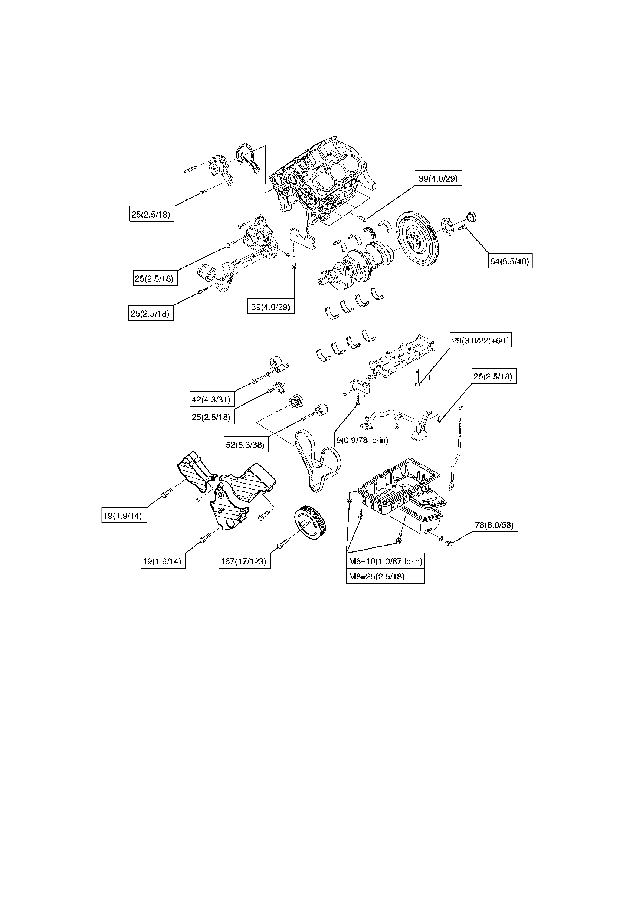
Crankshaft main bearing, Flywheel, Crankcase, Oil pan, Timing belt tensioner, Timing pulley, Timing belt
cover, Oil pump, Oil gallery, Oil strainer and Water pump
N·m (Kg·m/lbft)
E06RW039
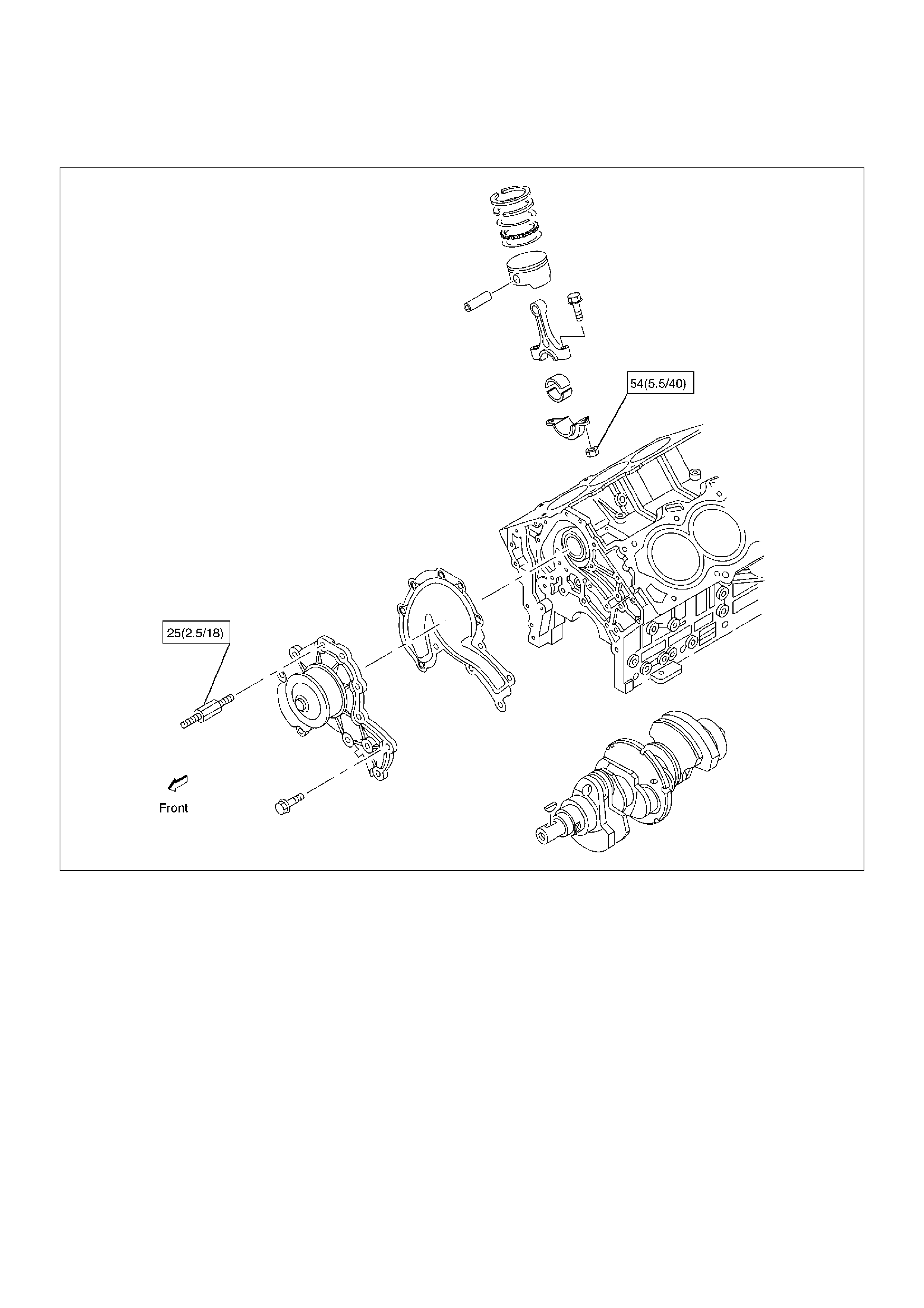
Connecting rod and Water pump
N·m (Kg·m/lbft)
E06RW042
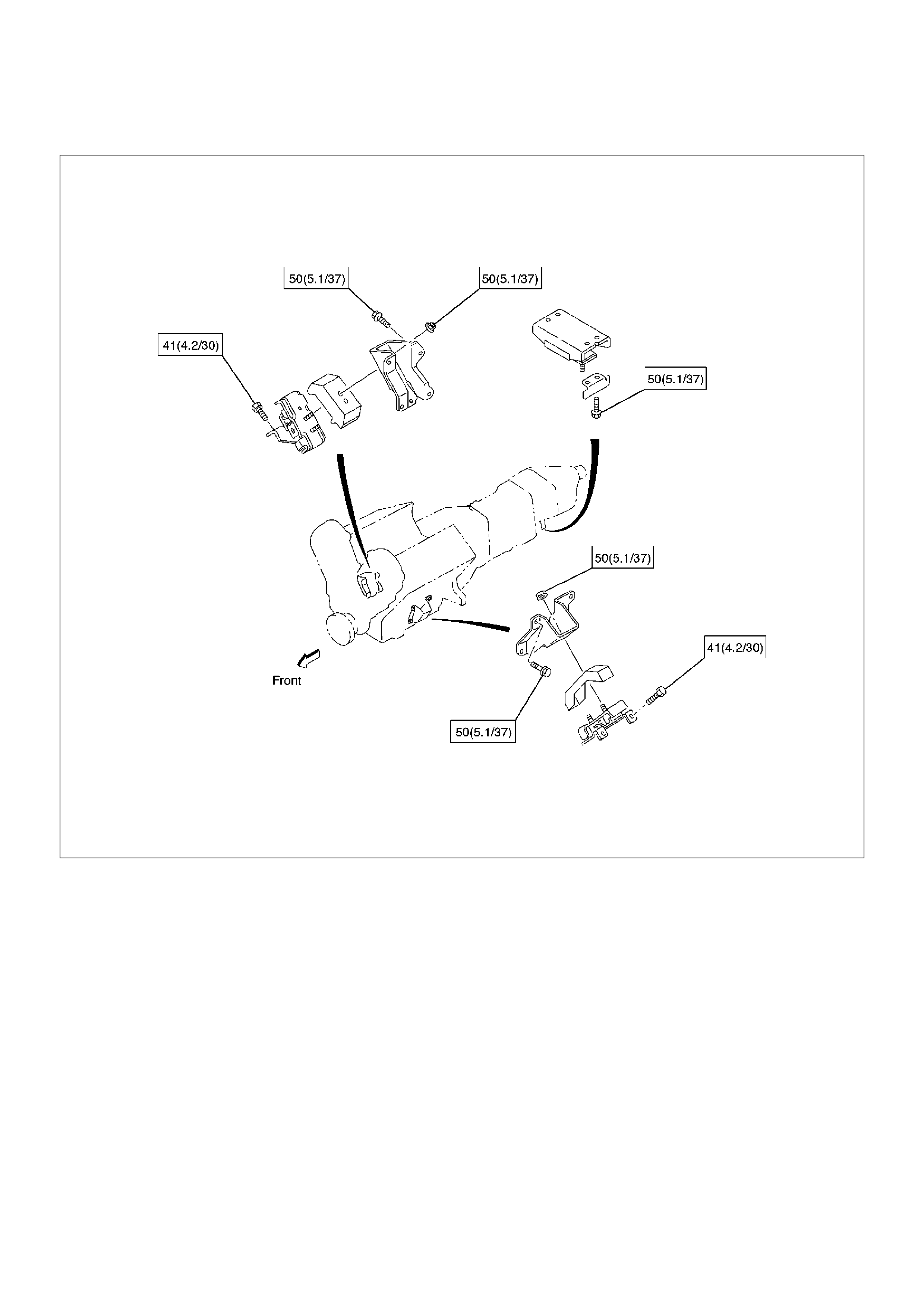
Engine mount N·m (Kg·m/lbft)
N·m (Kg·m/lbft)
E06RW040
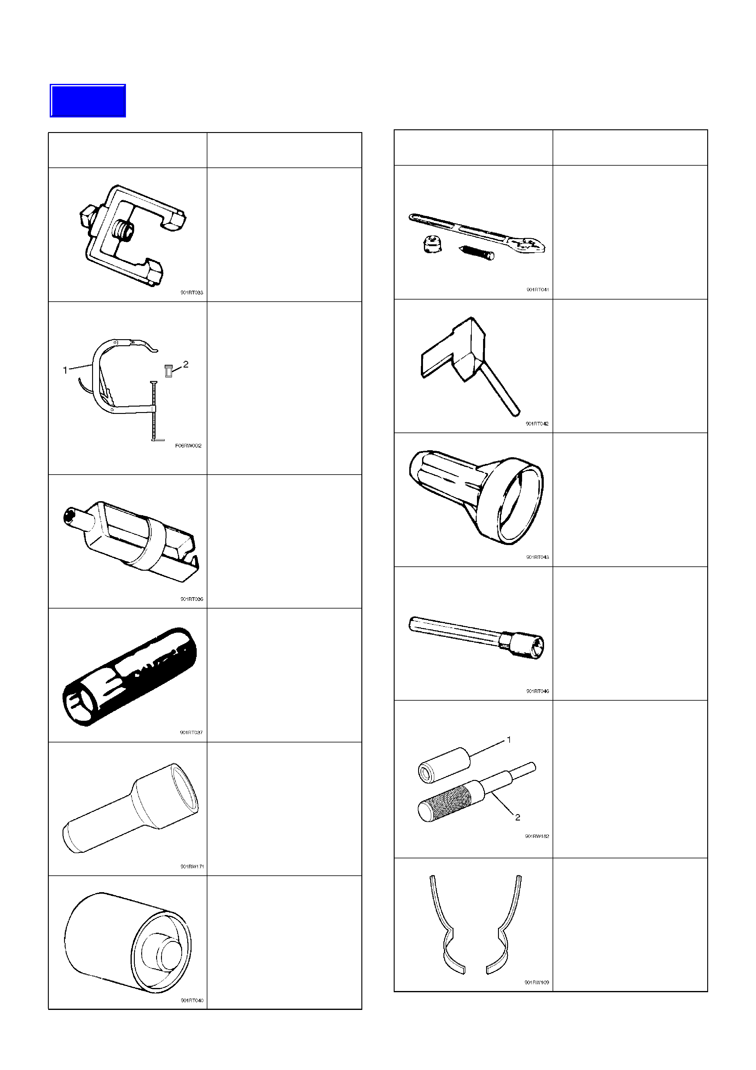
Special Tool
ILLUSTRATION TOOL NO.
TOOL NAME
5–8840–0011–0
(J–21687–02)
Remover; tie rod end
5–8840–2441–0
Set Number of Valve
Compressor
5–8840–2446–0
(J–8062)
Compressor; Valve
Spring (1)
5–8840–2547–0
(J–42898)
Adapter; Compressor
Valve Spring (2)
5–8840–0623–0
(J–37281)
Remover; Oil controller
5–8840–0624–0
(J–38537)
Installer; Oil controller
5–8840–2445–0
(J–42985)
Installer; Camshaft oil
seal
5–8840–2545–0
(J–39206)
Installer; Pilot bearing
5–8840–0133–0
(J–8614–01)
Holder; Crankshaft
5–8840–2153–0
(J–37228)
Seal cutter
5–8840–2286–0
(J–39201)
Installer; Real oil seal
9–8511–4209–0
(J–24239–1)
Cylinder head bolt
wrench
5–8840–2442–0
(J–42899)
Replacer; Valve guide
(set) (1,2)
5–8840–2548–0
(J–42687)
Installer; Valve guide (1)
5–8840–2549–0
(J–37985–1)
Remover; Valve guide (2)
5–8840–2444–0
(J–42689)
Adjusting Tool: Valve
clearance
ILLUSTRATION TOOL NO.
TOOL NAME
Techline
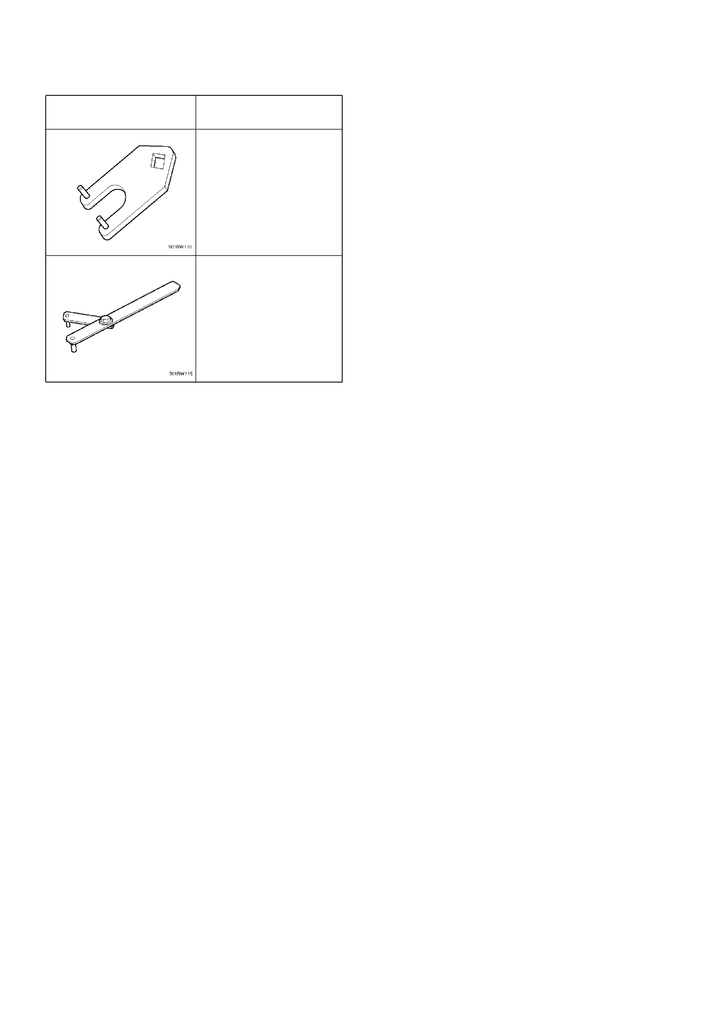
5–8840–2443–0
(J–42686)
Lever; Gear spring
5–8840–2447–0
(J–43041)
Holder; Universal
ILLUSTRATION TOOL NO.
TOOL NAME