
SECTION 6E1 - CHARGING SYSTEM
Service Precaution
Charging System
General Description
General On–Vehicle Inspection
Generator
Removal
Inspection
Installation
Disassembled View
Disassembly
Inspection and Repair
Reassembly
Bench Test
Main Data and Specifications
Service Precaution
WARNING: IF SO EQUIPPED WITH A
SUPPLEMENTAL RESTRAINT SYSTEM (SRS),
REFER TO THE SRS COMPONENT AND WIRING
LOCATION VIEW IN ORDER TO DETERMINE
WHETHER YOU ARE PERFORMING SERVICE ON
OR NEAR THE SRS COMPONENTS OR THE SRS
WIRING. WHEN YOU ARE PERFORMING SERVICE
ON OR NEAR THE SRS COMPONENTS OR THE SRS
WIRING, REFER TO THE SRS SERVICE
INFORMATION. FAILURE TO FOLLOW WARNINGS
COULD RESULT IN POSSIBLE AIR BAG
DEPLOYMENT, PERSONAL INJURY, OR
OTHERWISE UNNEEDED SRS SYSTEM REPAIRS.
CAUTION: Always use the correct fastener in the
proper location. When you replace a fastener, use
ONLY the exact part number for that application.
HOLDEN will call out those fasteners that require a
replacement after removal. HOLDEN will also call
out the fasteners that require thread lockers or
thread sealant. UNLESS OTHERWISE SPECIFIED,
do not use supplemental coatings (Paints, greases,
or other corrosion inhibitors) on threaded fasteners
or fastener joint interfaces. Generally, such
coatings adversely affect the fastener torque and
the joint clamping force, and may damage the
fastener. When you install fasteners, use the
correct tightening sequence and specifications.
Following these instructions can help you avoid
damage to parts and systems.
Charging System
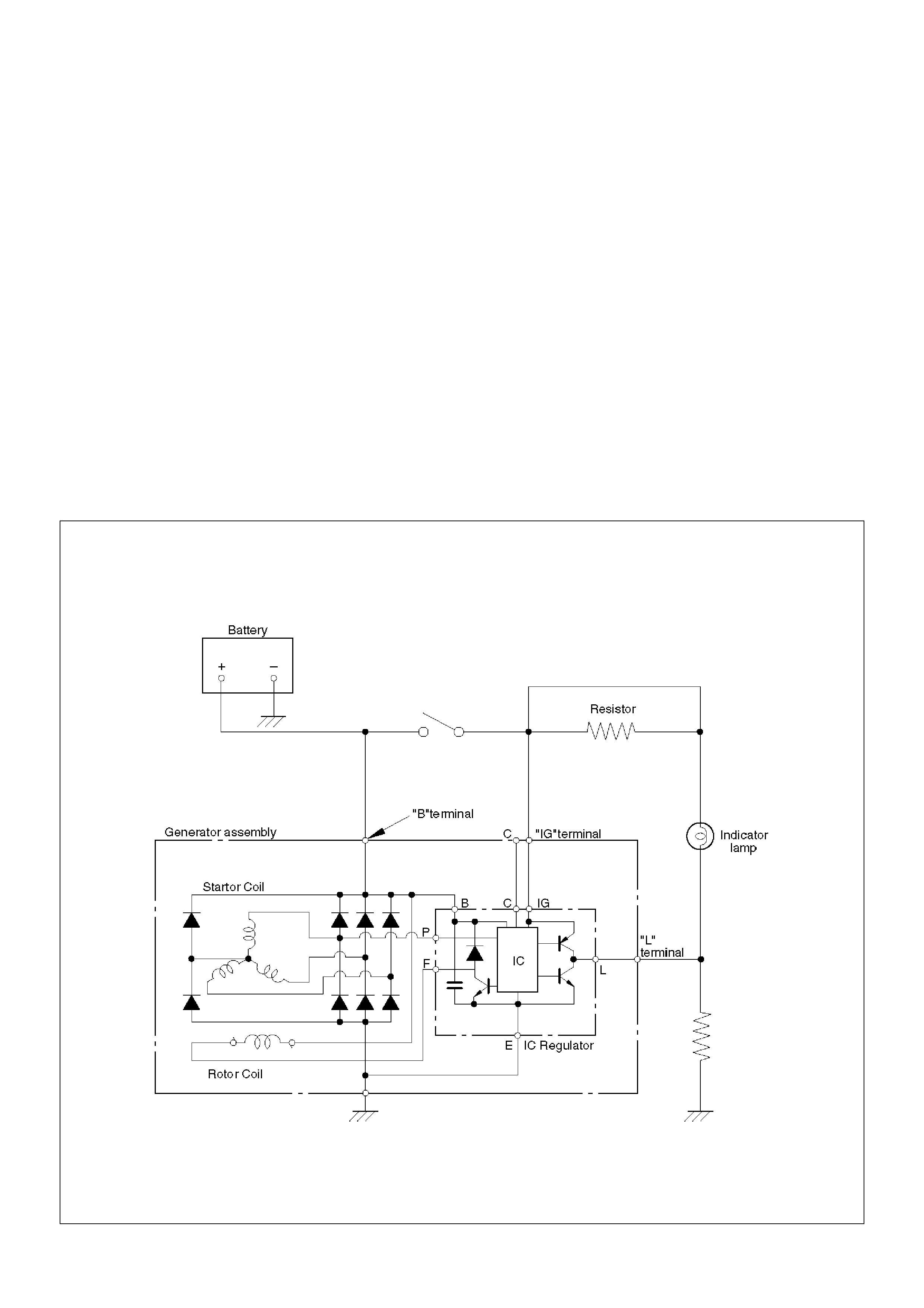
General Description
The IC integral regulator charging system and its main
components are connected as shown in the illustration.
The regulator is a solid state type and it is mounted
along with the brush holder assembly inside the
generator installed on the rear end cover.
The generator does not require particular maintenance
such as voltage adjustment.
The rectifier connected to the stator coil has eight
diodes to transform AC voltage into DC voltage.
This DC voltage is connected to the output terminal of
generator.
General On–Vehicle Inspection
The operating condition of charging system is indicated
by the charge warning lamp. The warning lamp comes
on when the starter switch is turned to “ON” position.
The charging system operates normally if the lamp goes
off when the engine starts.
If the warning lamp shows abnormality or if
undercharged or overcharged battery condition is
suspected, perform diagnosis by checking the charging
system as follows:
1. Check visually the belt and wiring connector.
2. With the engine stopped, turn the stator switch to
“ON” position and observe the warning lamp.
If lamp does not come on:
Disconnect wiring connector from generator, and
ground the terminal “L” on connector side.
If lamp comes on:
Repair or replace the generator.
F06RW009
Generator
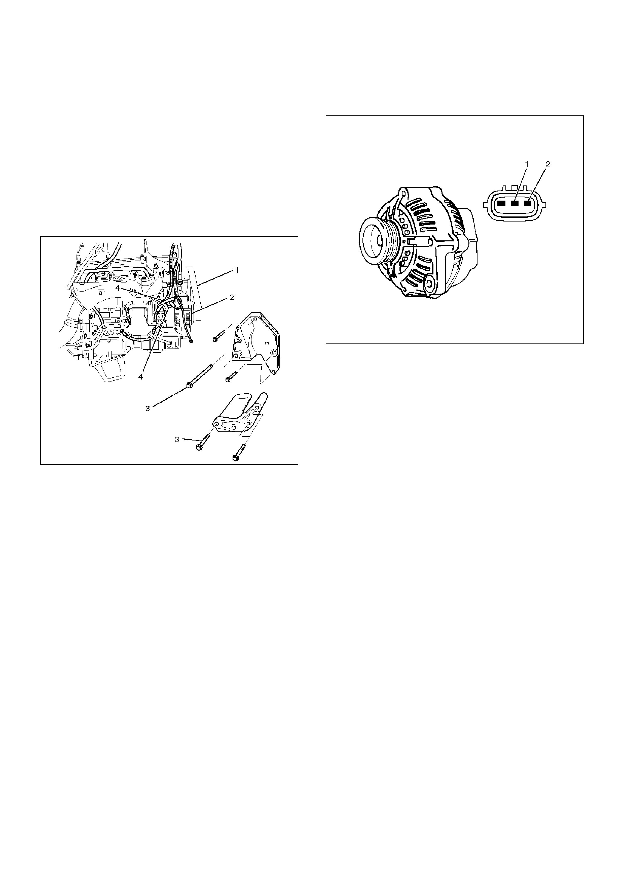
Removal
1. Disconnect battery ground cable.
2. Move drive belt tensioner to loose side using
wrench then remove drive belt (1).
3. Disconnect the wire from terminal “B” and
disconnect the connector (4).
4. Remove generator fixing bolt (3).
5. Remove generator assembly (2).
060RW002
Inspection
1. Disconnect the wiring connector from generator.
2. With the engine stopped, turn starter switch to “ON”
and connect a voltmeter between connector
terminal L (2) and ground or between terminal IG (1)
and ground.
066RW001
If voltage is not present, the line between battery
and connector is disconnected and so requires
repair.
3. Reconnect the wiring connector to the generator,
run the engine at middle speed, and turn off all
electrical devices other than engine.
4. Measure battery voltage. If it exceeds 16V, repair or
replace the generator.
5. Connect an ammeter to output terminal of
generator, and measure output current under load
by turning on the other electrical devices (eg., head
lights). At this time, the voltage must not be less
than 13V.
Installation
1. Install generator assembly to the position to be
installed.
2. Install generator assembly and tighten the fixing
bolts to the specified torque.
Torque:
M10 bolt: 41 N·m (4.2 Kg·m/30 lb ft)
M8 bolt: 21 N·m (2.1 Kg·m/15 lb ft)
3. Connect wiring harness connector and direct
terminal“B”.
4. Move drive belt tensioner to loose side using
wrench, then install drive belt to normal position.
5. Reconnect battery ground cable.
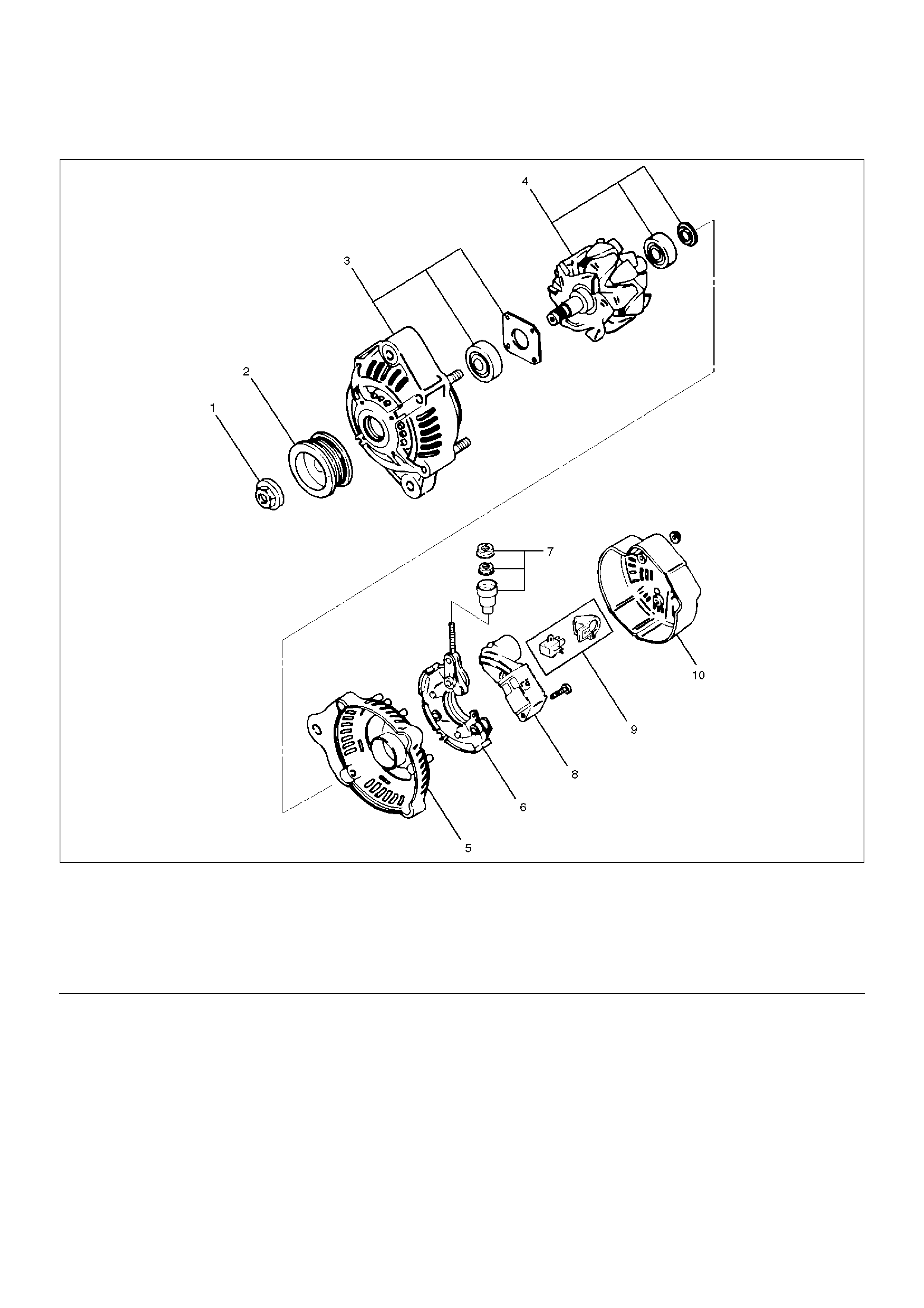
Disassembled View
066RW007
EndOFCallout
Legend
(1) Pulley Nut
(2) Pulley
(3) Front Cover Assembly
(4) Rotor Assembly
(5) Rear End Cover
(6) Rectifier
(7) Terminal Insulator and Nut
(8) Regulator Assembly
(9) Brush Holder Assembly
(10) Rear Cover
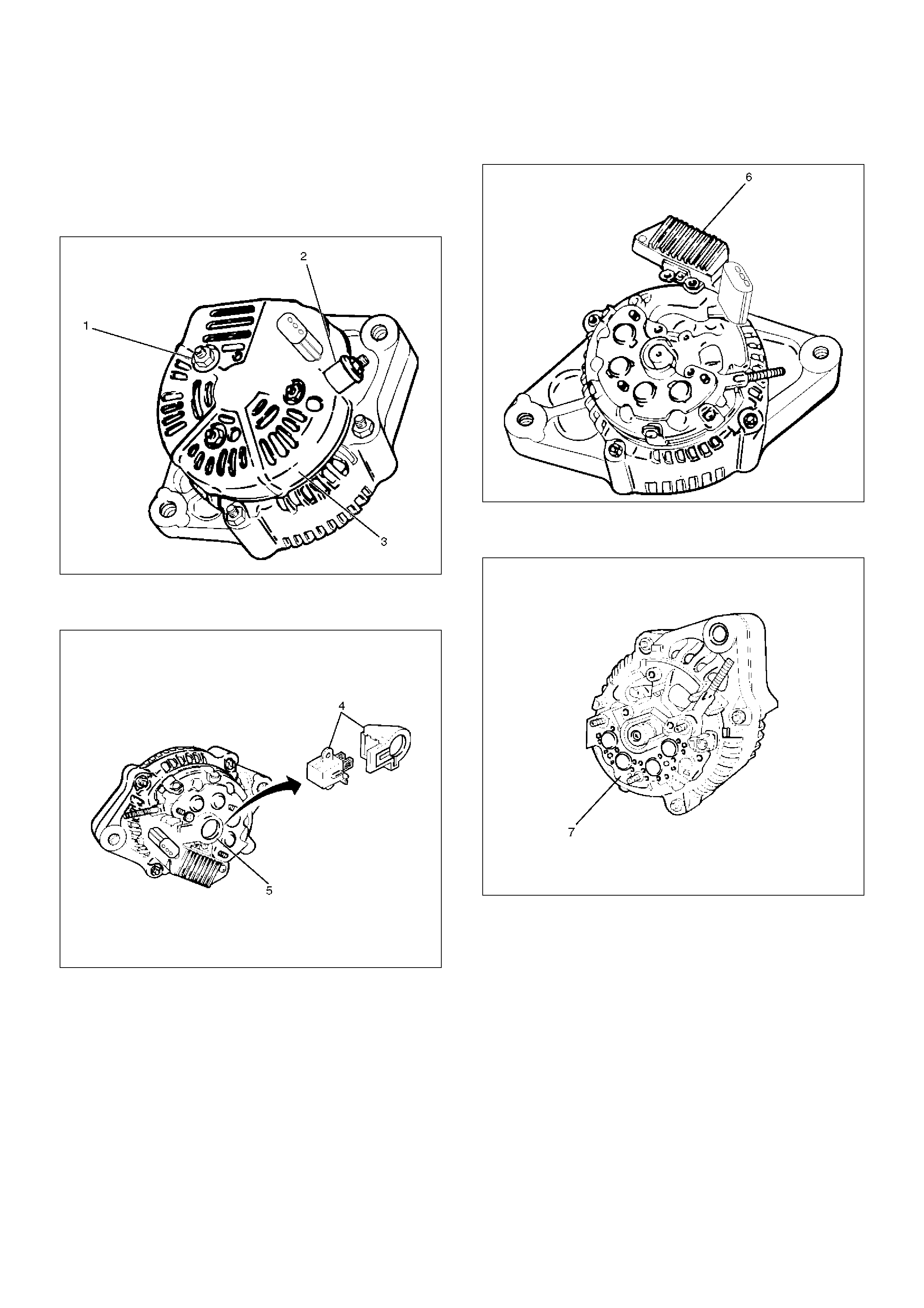
Disassembly
1. Terminal insulator and nut(2).
2. Remove three nuts(1) on the rear cover and a nut
on terminal B and insulator, then remove the rear
cover(3).
060RW005
3. Remove two screws that fix the brush holder(5) and
rectifier, then remove the brush holder assembly(4).
060RW004
4. Remove three screws on the IC regulator, then the
IC regulator assembly(6).
060RW003
5. Remove four screws that fix rectifier(7) and stator
lead wires.
066RW004
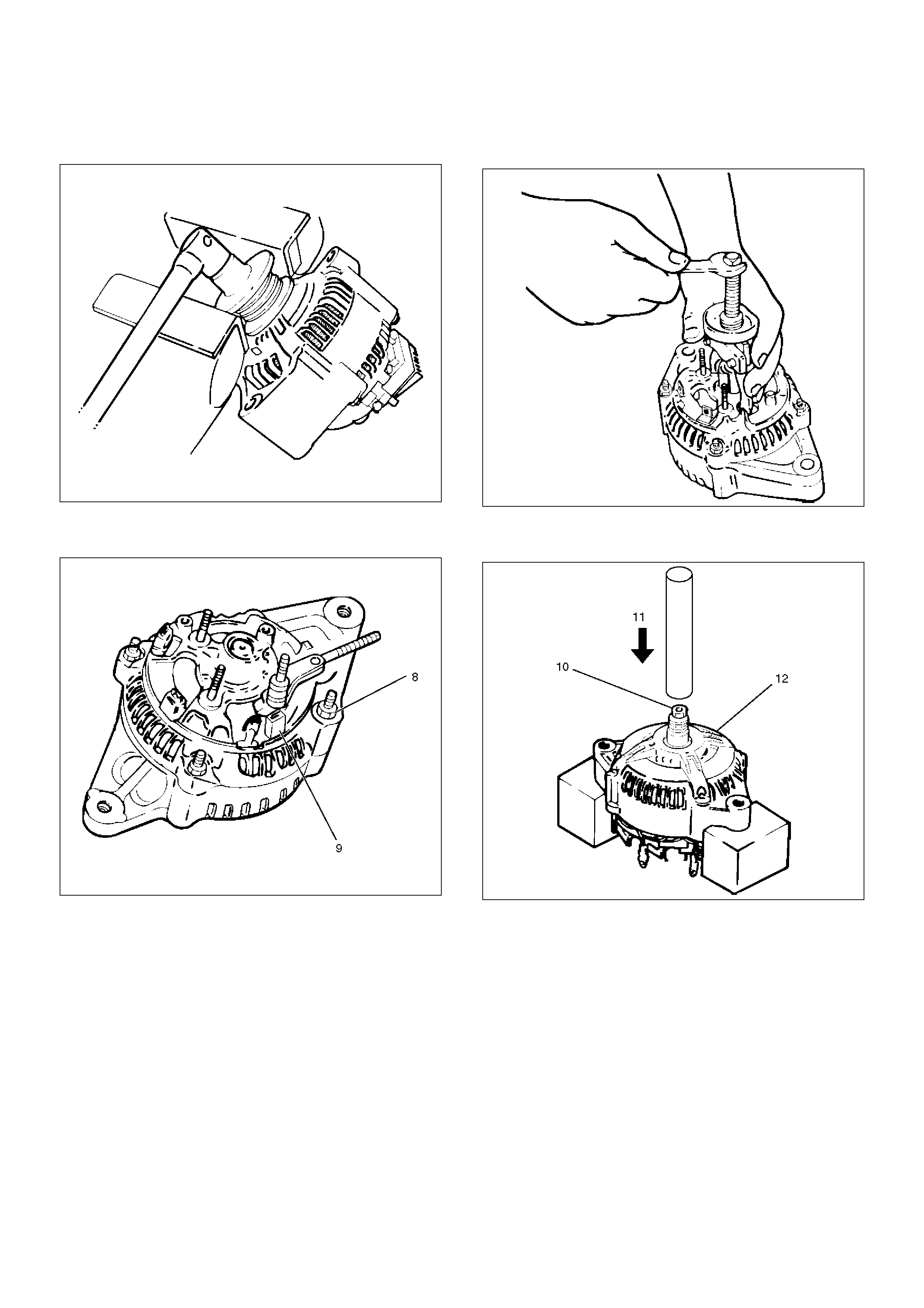
6. Secure the pulley directly in the vise between two
copper plates, and remove the nut and pulley.
066RS010
7. Remove four nuts(8) that secure the front cover
assembly and rear end cover, and an insulator(9).
066RW005
8. Use the puller to remove the rear end cover.
9. Rotor assembly
066RS012
10. Pull the rotor assembly(10) off the front cover
assembly(12) using a bench press(11).
066RW006
Inspection and Repair
Repair or replace necessary parts if extreme wear or
damage is found during inspection.
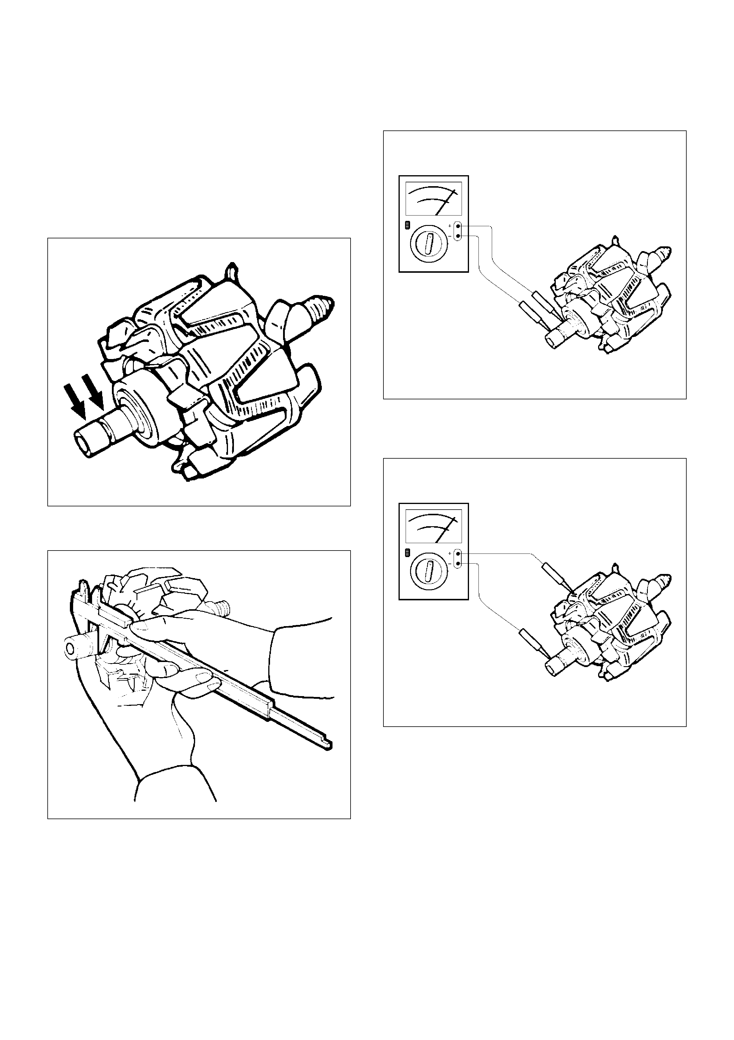
Rotor Assembly
1. Check the rotor slip ring surfaces for contamination
and roughness. If rough, polish with #500—600
sandpaper.
066RS014
2. Measure the slip ring diameter, and replace if it
exceeds the limit.
066RS015
3. Check resistance between slip rings, and replace if
there is no continuity.
066RS016
4. Check for continuity between slip ring and rotor
core.
In case of continuity, replace the rotor assembly.
066RS017
Stator Coil
1. Measure resistance between respective phases.
2. Measure insulation resistance between stator coil
and core with a mega–ohmmeter.
If less than standard, replace the coil.
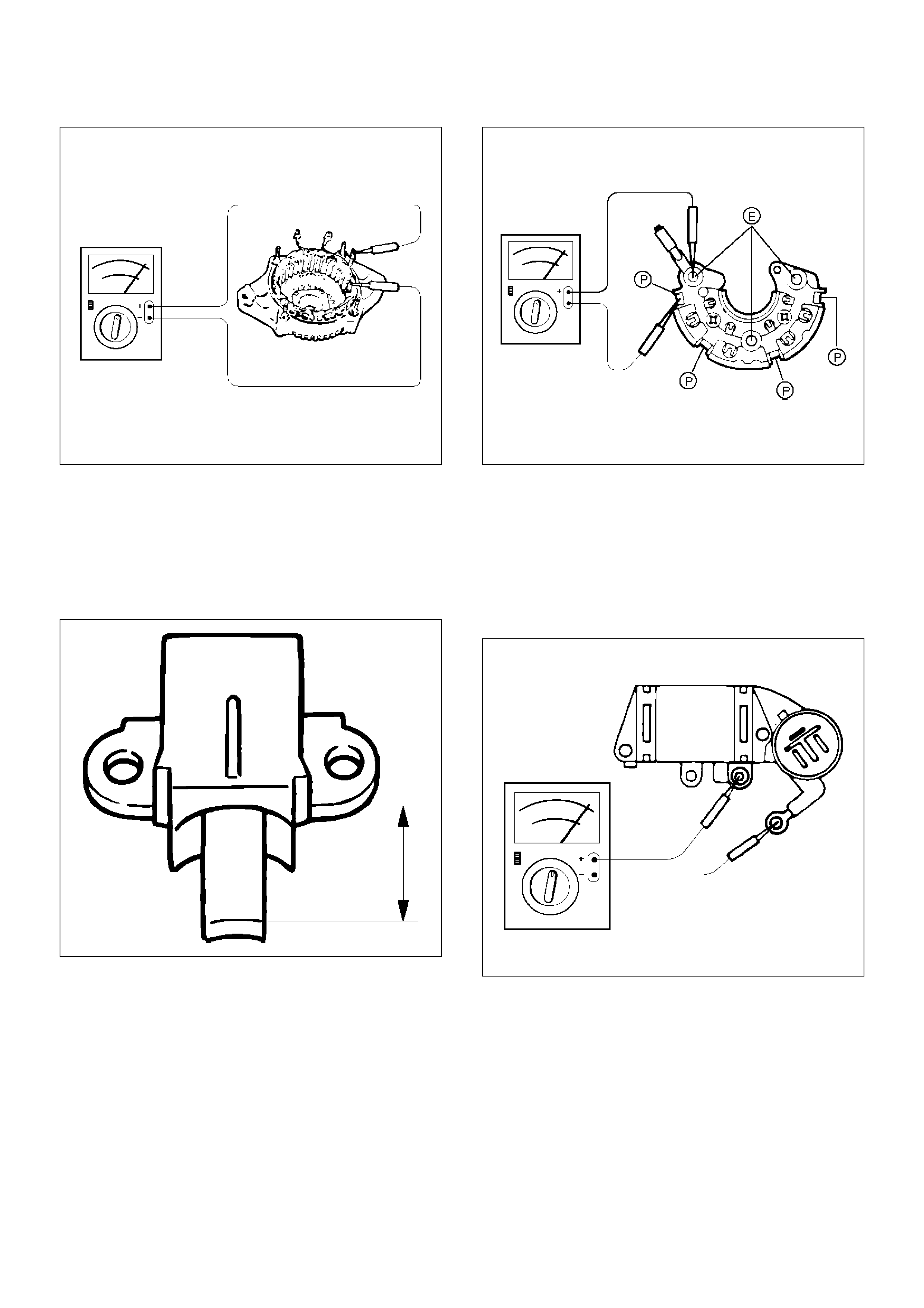
066RS018
Brush
Measure the brush length.
If more than limit, replace the brush.
Standard: 10.mm (0.4134 in)
Limit: 8.4.mm (0.3307 in)
066RS019
Rectifier Assembly
Check for continuity across “P” and “E” in the ´ 100W
range of multimeter.
066RW002
Change polarity, and make sure that there is continuity
in one direction, and not in the reverse direction. In
case of continuity in both directions, replace the rectifier
assembly.
IC Regulator Assembly
Check for continuity across “B” and “F” in the ´ 100W
range of multimeter.
066RS021
Change polarity, and make sure that there is continuity
in one direction, and not in the reverse direction. In
case of continuity in both directions, replace the IC
regulator assembly.
Reassembly
To reassemble, follow the disassembly steps in the
reverse order, noting the following points:
1. Using a press with a socket wrench attached,
reassemble rotor and rear end cover assembly in
the front cover.
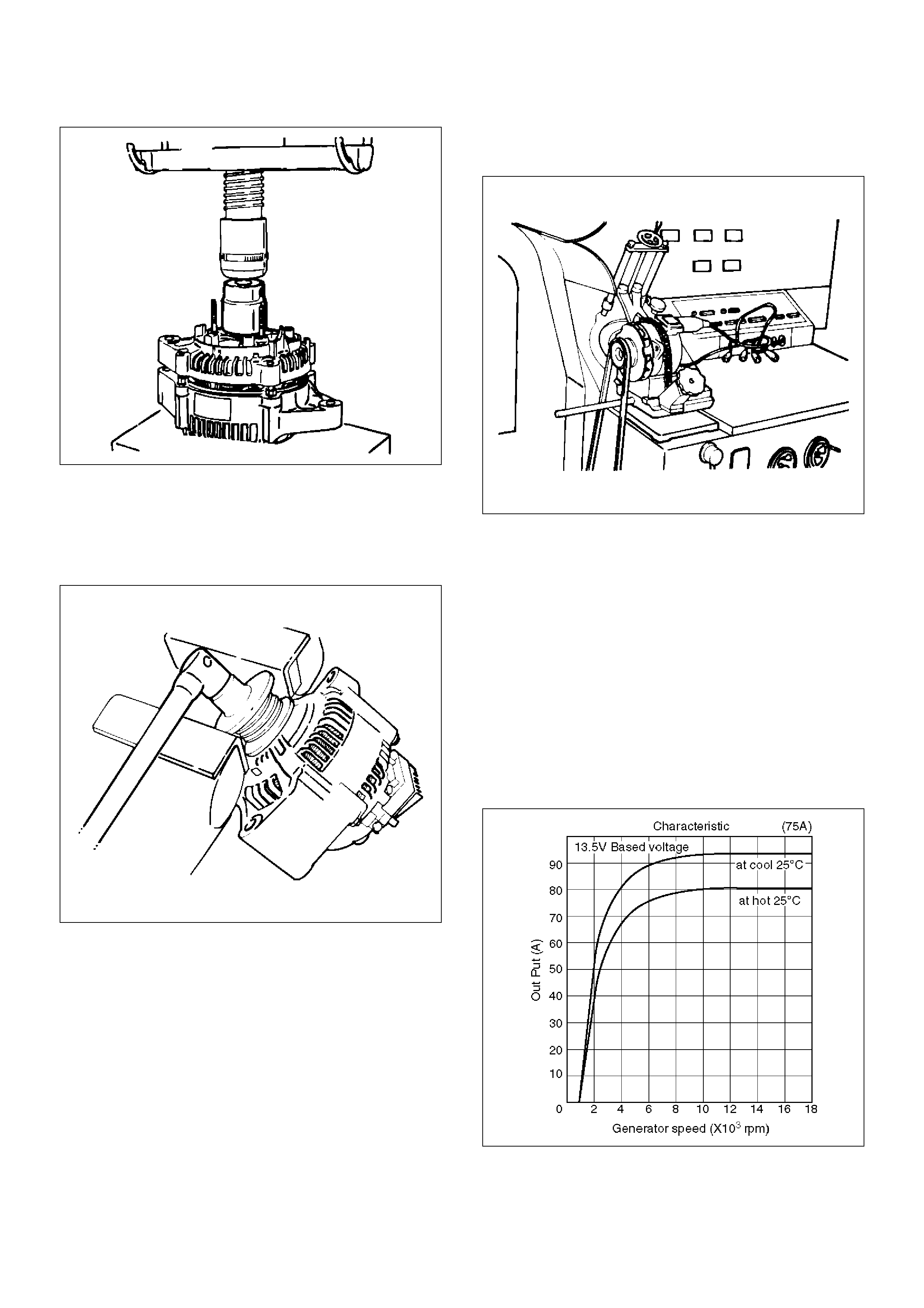
066RS022
2. Install pulley on the rotor.
Secure the pulley directly in the vise between two
copper plates, and tighten nut to the specified
torque.
Torque: 111 N·m (11.3 Kg·m/82 lb ft)
066RS010
Bench Test
Conduct a bench test of the generator.
066RS023
Preparation
Remove generator from the vehicle (see“Generator
removal”).
1. Secure generator to the bench test equipment and
connect wires.
Terminal “IG” for energization
Terminal “L” for neutral (warning lamp)
Terminal “B” for output
2. Conduct the generator characteristic test.
Characteristics of generator are shown in
illustration.
Repair or replace the generator if its outputs are
abnormal.
B06RW001

Main Data and Specifications
General Specifications
Parts Number (Nippon denso) 102211—5030
Model ACHD04
Rated voltage 12 V
Rated output 75 A
Rotating direction (As viewed from pulled) Clockwise
Pulley effective diameter 50 mm (1.97 in)
Weight 44 N (33 lb)