
SERVICE 6G1 - ENGINE LUBRICATION
Service Precaution
General Description
Oil Pump
Oil Pump and Associated Parts
Removal
Inspection and Repair
Reassembly
Oil Pan and Crankcase
Removal
Installation
Oil Pump
Removal
Installation
Oil Pump Oil Seal
Removal
Installation
Oil Filter
Removal
Installation
Main Data and Specification
Special Tool
Service Precaution
WARNING: IF SO EQUIPPED WITH A
SUPPLEMENTAL RESTRAINT SYSTEM (SRS),
REFER TO THE SRS COMPONENT AND WIRING
LOCATION VIEW IN ORDER TO DETERMINE
WHETHER YOU ARE PERFORMING SERVICE ON
OR NEAR THE SRS COMPONENTS OR THE SRS
WIRING. WHEN YOU ARE PERFORMING SERVICE
ON OR NEAR THE SRS COMPONENTS OR THE SRS
WIRING, REFER TO THE SRS SERVICE
INFORMATION. FAILURE TO FOLLOW WARNINGS
COULD RESULT IN POSSIBLE AIR BAG
DEPLOYMENT, PERSONAL INJURY, OR
OTHERWISE UNNEEDED SRS SYSTEM REPAIRS.
CAUTION: Always use the correct fastener in the
proper location. When you replace a fastener, use
ONLY the exact part number for that application.
HOLDEN will call out those fasteners that require a
replacement after removal. IHOLDEN will also call
out the fasteners that require thread lockers or
thread sealant. UNLESS OTHERWISE SPECIFIED,
do not use supplemental coatings (Paints, greases,
or other corrosion inhibitors) on threaded fasteners
or fastener joint interfaces. Generally, such
coatings adversely affect the fastener torque and
the joint clamping force, and may damage the
fastener. When you install fasteners, use the
correct tightening sequence and specifications.
Following these instructions can help you avoid
damage to parts and systems.
Techline
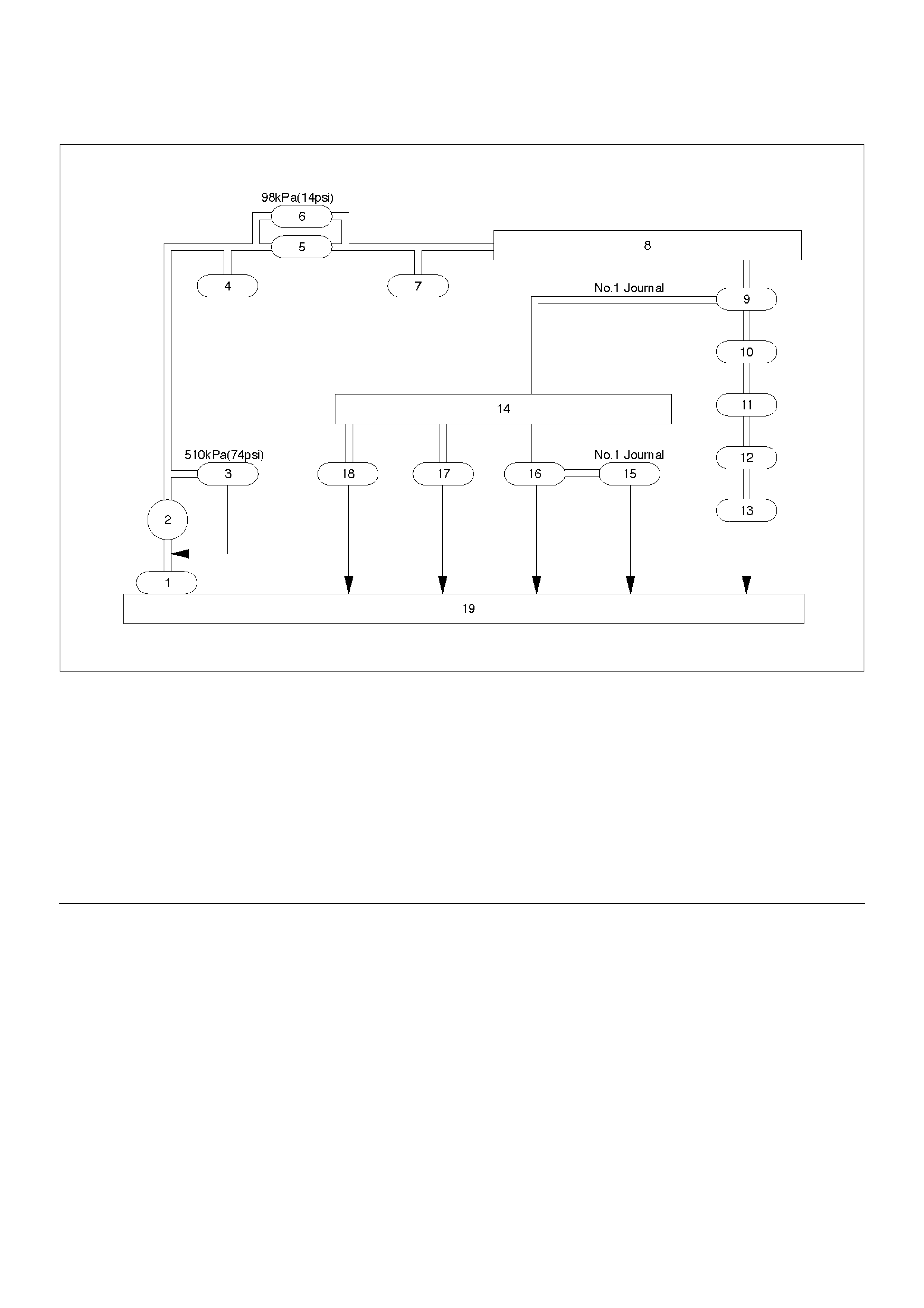
General Description
C06RW002
EndOFCallout
Legend
(1) Oil Strainer
(2) Oil Pump
(3) Relief Valve
(4) Oil Pressure Switch
(5) Oil Filter
(6) Safety Valve
(7) Oil Pressure Unit
(8) Oil Gallery
(9) Crankshaft Bearing
(10) Crankshaft
(11) Connecting Rod Bearing
(12) Connecting Rod
(13) Piston
(14) Oil Gallery; Cylinder Head
(15) Camshaft
(16) Camshaft Journal
(17) Front Journal; Camshaft Drive Gear
(18) Rear Journal; Camshaft Drive Gear
(19) Oil Pan
Oil Pump
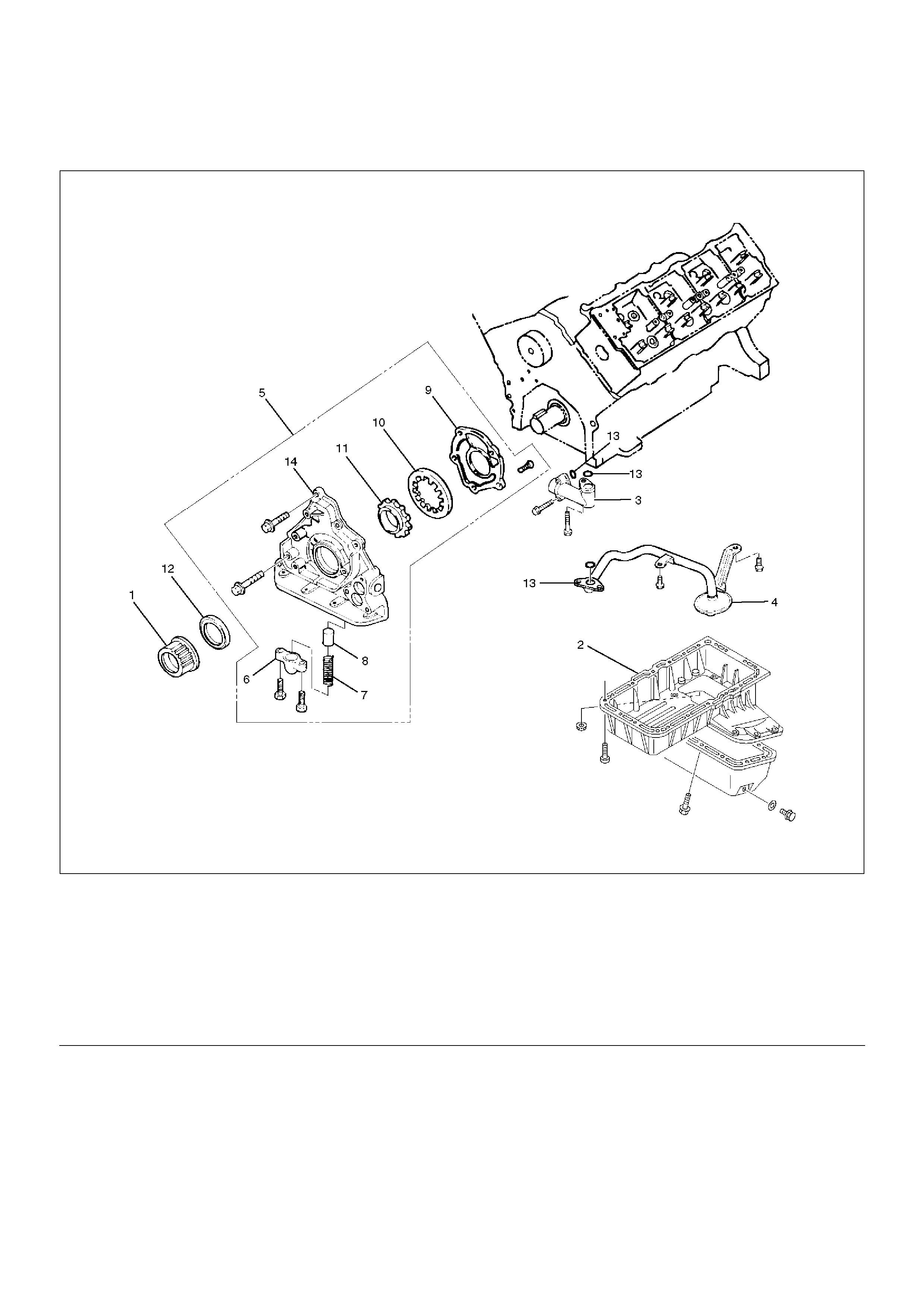
Oil Pump and Associated Parts
051RW005
EndOFCallout
Removal
1. Remove crankshaft timing pulley.
2. Remove crankcase with oil pan.
3. Remove oil pipe.
4. Remove oil strainer.
5. Remove oil pump assembly.
6. Remove plug.
7. Remove spring.
8. Remove relief valve.
9. Remove oil pump cover.
10. Remove driven gear.
11. Remove drive gear.
12. Remove oil seal.
13. Remove O-ring.
Legend
(1) Crankshaft Timing Pulley
(2) Crankcase with Oil Pan
(3) Oil Pipe
(4) Oil Strainer
(5) Oil Pump Assembly
(6) Plug
(7) Spring
(8) Relief Valve
(9) Oil Pump Cover
(10) Driven Gear
(11) Drive Gear
(12) Oil Seal
(13) O-ring
(14) Oil Pump Body
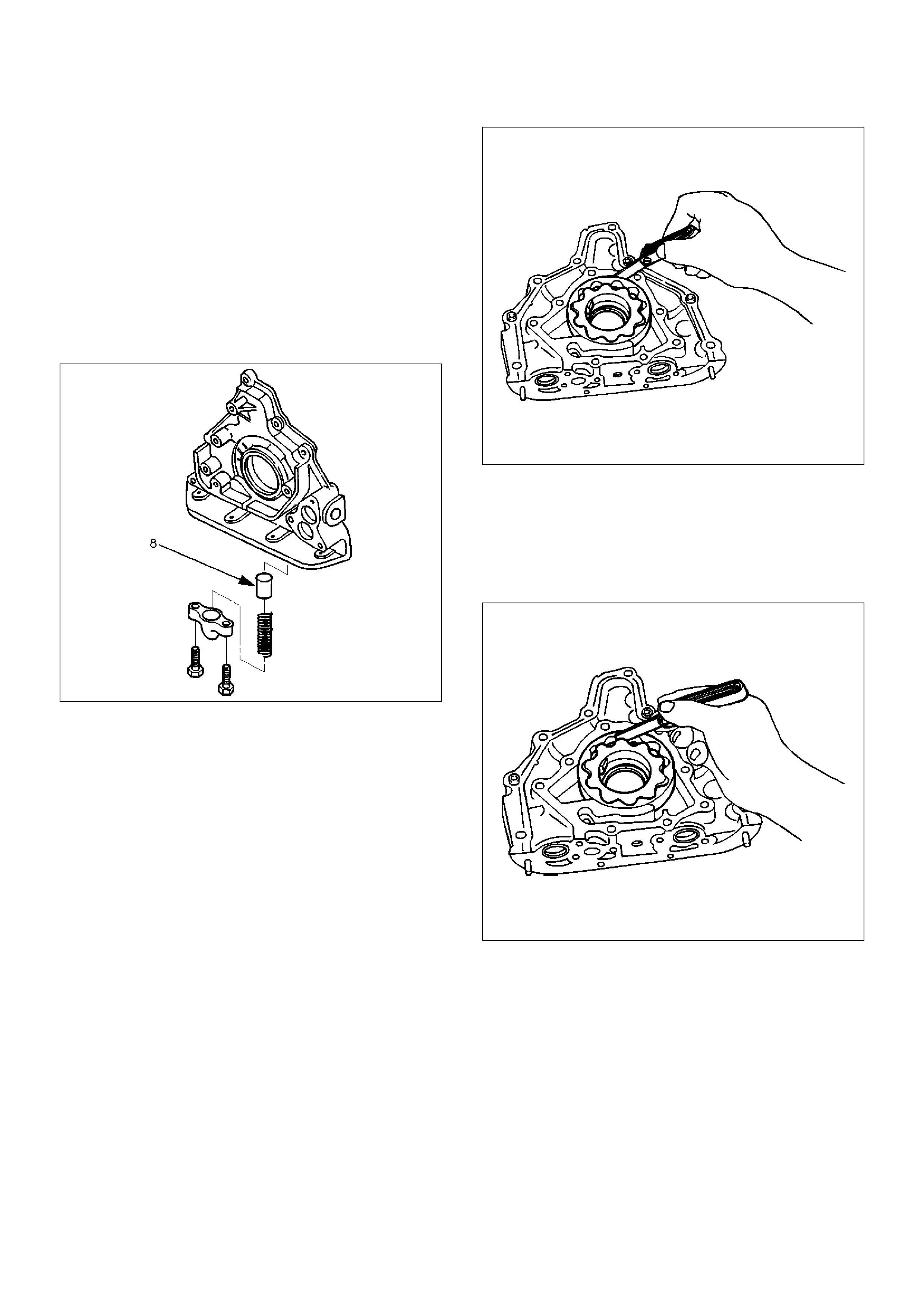
Inspection and Repair
CAUTION: Make necessary correction or parts
replacement if wear, damage or any other abnormal
conditions are found during inspection.
Relief Valve (8)
• Check to see that the relief valve slides freely.
• The oil pump must be replaced if the relief valve does
not slide freely.
• Replace the spring and/or the oil pump assembly (5)
if the spring is damaged or badly worn.
051RS002
Body (14) and Gears (10, 11)
The pump assembly must be replaced if one or more of
the conditions below is discovered during inspection.
• Badly worn or damaged driven gear (10).
• Badly worn drive gear (11) driving face.
• Badly scratched or scored body sliding face (14) or
driven gear (10).
• Badly worn or damaged gear teeth.
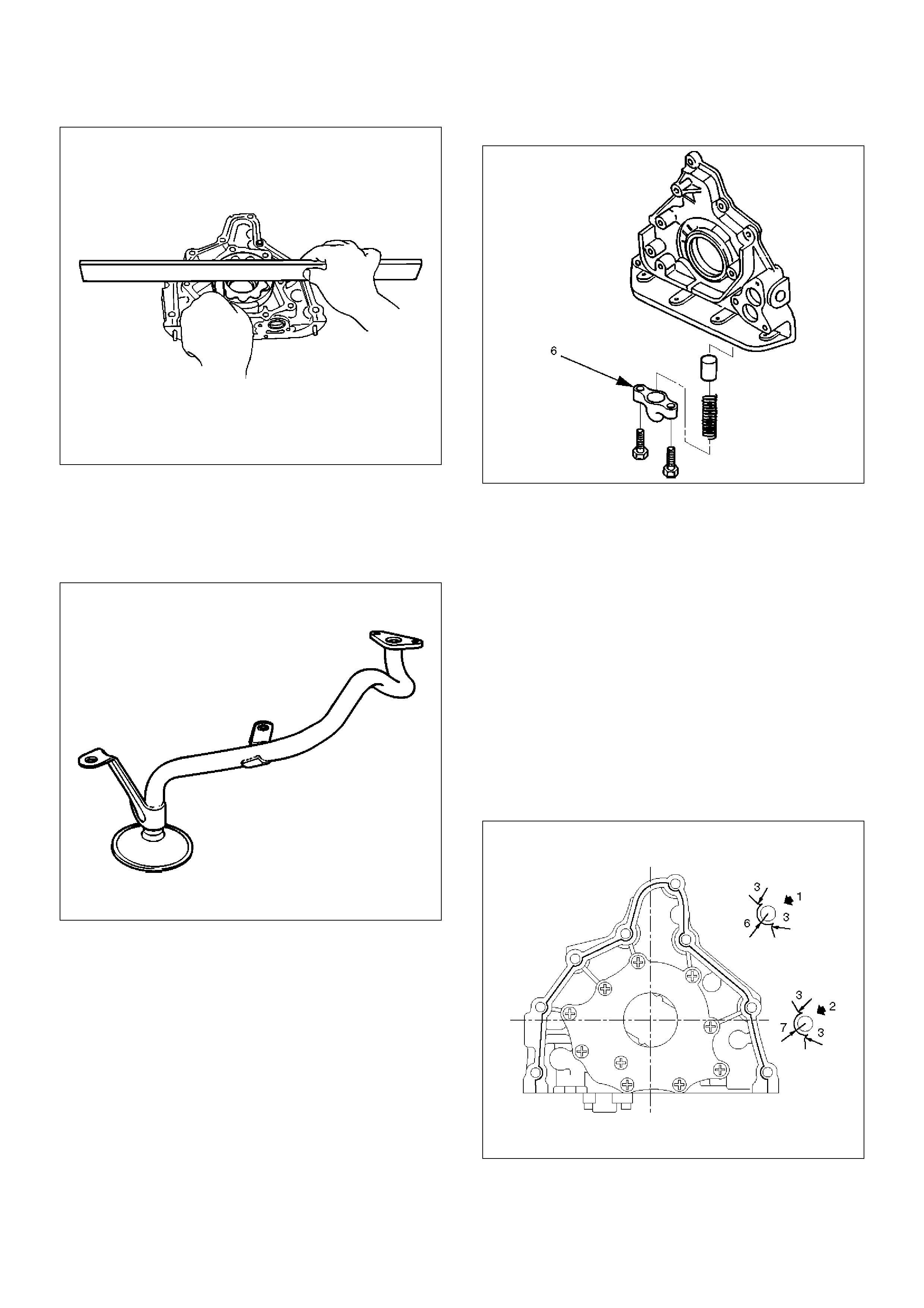
Measure the clearance between the body and the
driven gear with a feeler gauge.
Standard : 0.10 mm–0.18 mm
(0.0039 in.–0.0070 in)
Limit : 0.20mm (0.0079 in)
051RS004
• Measure the clearance between the drive gear and
driven gear with a feeler gauge.
Standard : 0.11 mm–0.24 mm
(0.0043 in–0.0094 in)
Limit : 0.35mm (0.0138 in)
051RS003
• Measure the side clearance with a precision straight
edge and a feeler gauge.
Clearance
Standard : 0.03 mm–0.09 mm
(0.0011 in–0.0035 in)
Limit : 0.15mm (0.0059 in)
051RS005
Oil Strainer
Check the oil strainer for cracking and scoring. If
cracking and scoring are found, the oil strainer must be
replaced.
051RS006
Reassembly
1.Install drive gear (11).
2.Install driven gear (10).
3.Install oil pump cover (9) and first, loosely tighten all
of the attaching screws. Next, tighten the attaching
screws to the specified torque.
Torque : 10 N·m (1.0 Kg·m/89 lb in)
After installation, check that the gear rotates
smoothly.
4.Install relief valve (8) and apply engine oil to the
relief valve and spring (7).
5.Install spring (7).
6.Install the plug (6).
Torque : 8 N·m (0.8 Kg·m/69 lb in)
051RS007
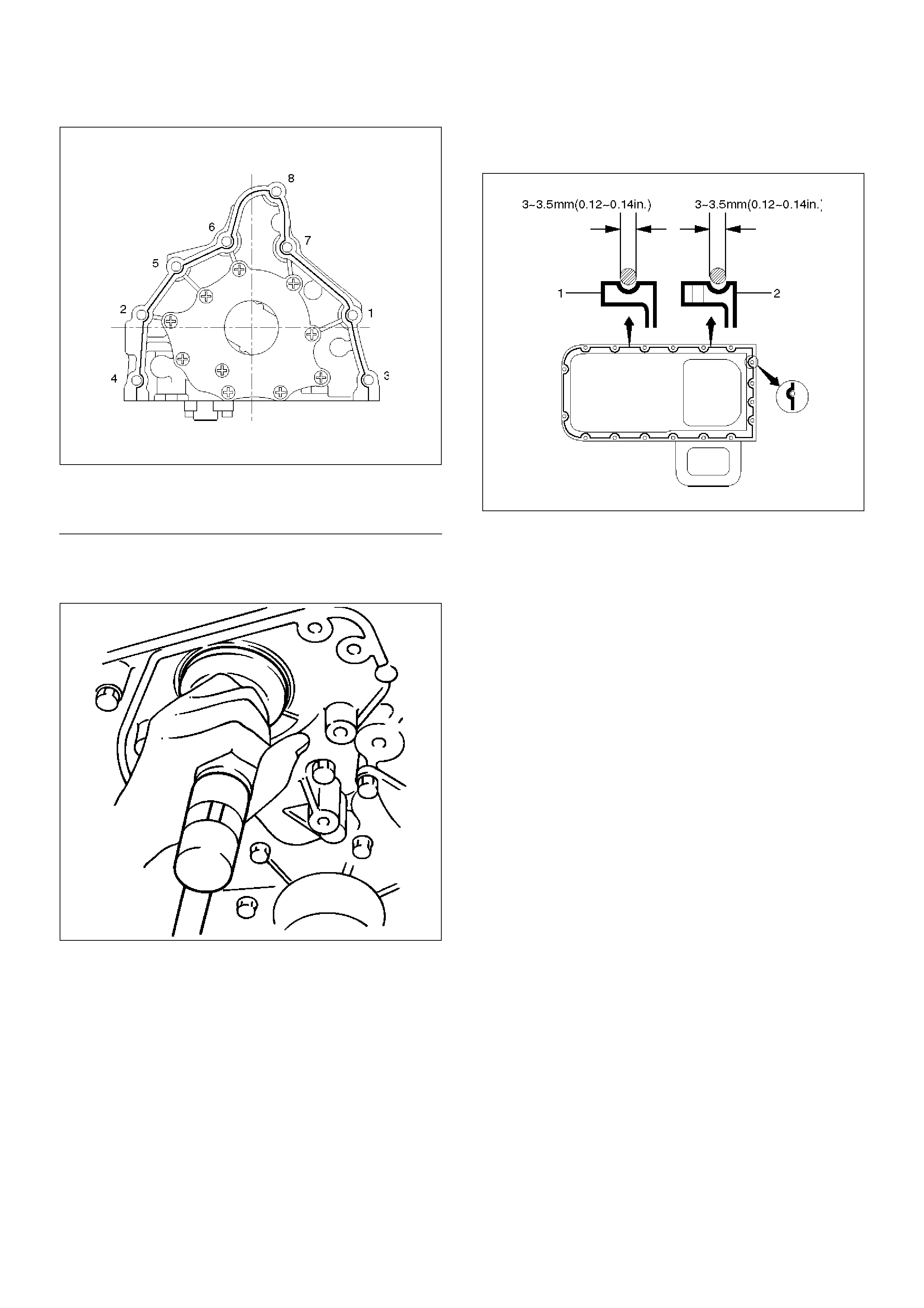
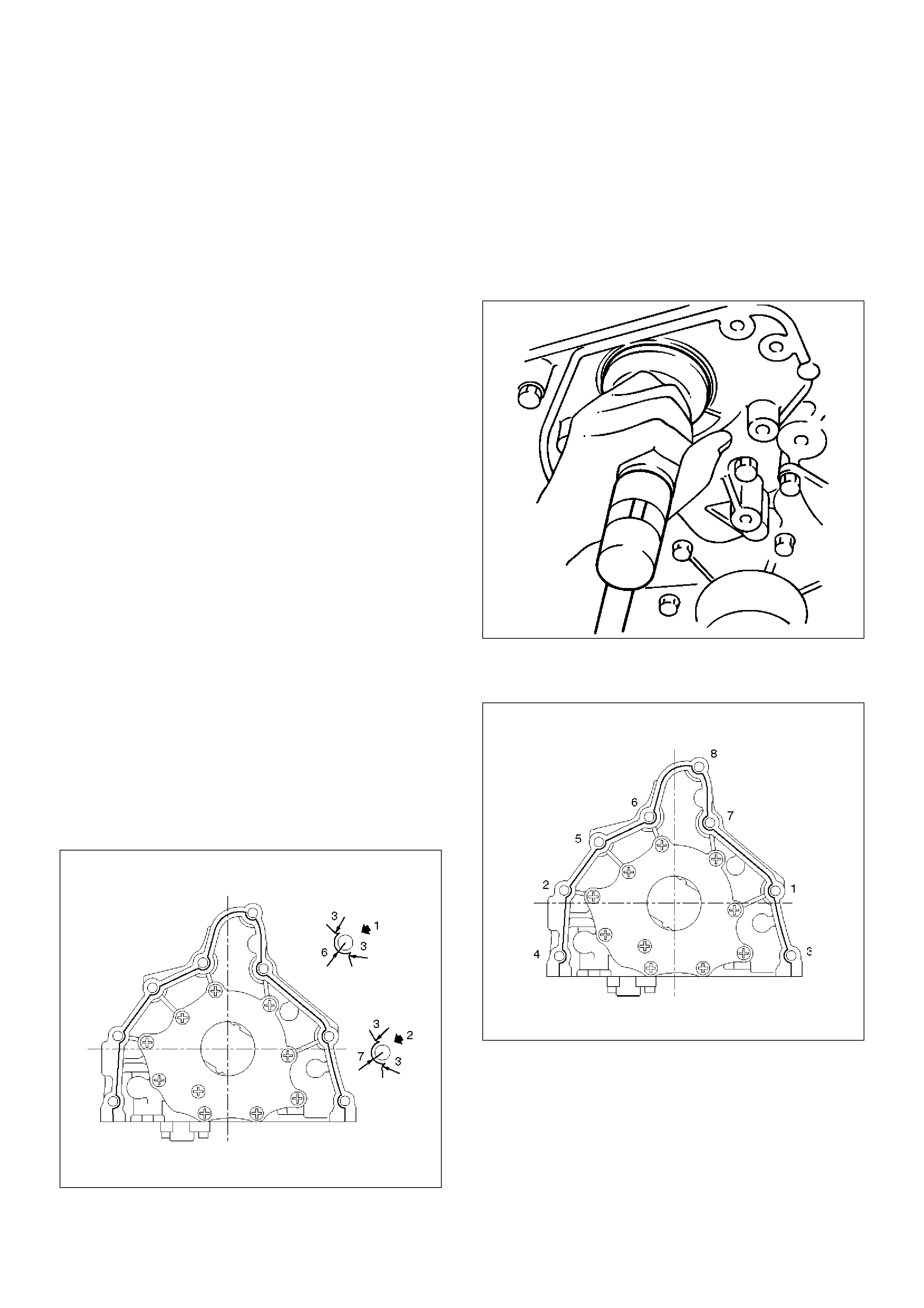
7.Install oil pump assembly (5).
•Carefully remove any oil from the cylinder body
and the pump. Apply sealant (TB–1207B or
equivalent) to the pump fitting face as shown in
illustration. Take care that sealant is not applied
to oil port surfaces. The oil pump assembly must
be installed within 5 minutes after sealant
application before the sealant hardens.
CAUTION: Do not apply an excessive amount of
sealant to the contact surface. Applying too much
sealant will overflow the contact surfaces. This
could cause serious damage to the engine.
• Attach oil pump assembly to cylinder body.
• Tighten the oil pump fixing bolts.
Torque : 25 N·m (2.5 Kg·m/18 lb·ft)
051RW002
051RW001
EndOFCallout
8. Install the new oil seal (12). Apply engine oil to the
oil seal lip before installation then use 5–8840–
2287–0 oil seal Installer, install oil seal.
015RS001
9. Install oil strainer (4) with O-ring (13).
Torque: 25 N·m (2.5 Kg·m/18 lb ft)
10. Install oil pipe (3) with O-ring (13).
Torque: 25 N·m (2.5 Kg·m/18 lb ft)
11. Install crankcase with oil pan (2).
• Remove oil on crankcase mounting surface and
dry the surface.
• Apply a proper 4.5 mm (0.7 in) wide bead of
sealant (TB1207C or equivalent) to the
crankcase mounting surface. The bead must be
continuous.
• The crankcase must be installed within 5 minutes
after sealant application before the sealant
hardens.
• Tighten fixing bolts to the specified torque.
Torque : 10 N·m (1.0 Kg·m/89 lb in)
013RW010
12. Install crankshaft timing pulley.
Legend
(1) Around Bolt Holes
(2) Around Dowel Pin
Oil Pan and Crankcase
Removal
1. Disconnect battery ground cable.
2. Drain engine oil.
3. Lift vehicle by supporting the frame.
4. Remove front wheels.
5. Remove oil level dipstick from level gauge tube.
6. Remove stone guard.
7. Remove radiator under fan shroud.
8. Remove suspension cross member fixing bolts, 2
pcs each per side and remove suspension cross
member.
9. Remove pitman arm and relay lever assembly,
using the 5–8840–2005–0 remover, remove pitman
arm from the steering unit and remove four fixing
bolts for relay lever assembly.
10. Remove axle housing assembly four fixing bolts
from housing isolator side and mounting bolts from
wheel side. At this time support the axle with a
garage jack and remove axle housing assembly.
11. Remove oil pan fixing bolts.
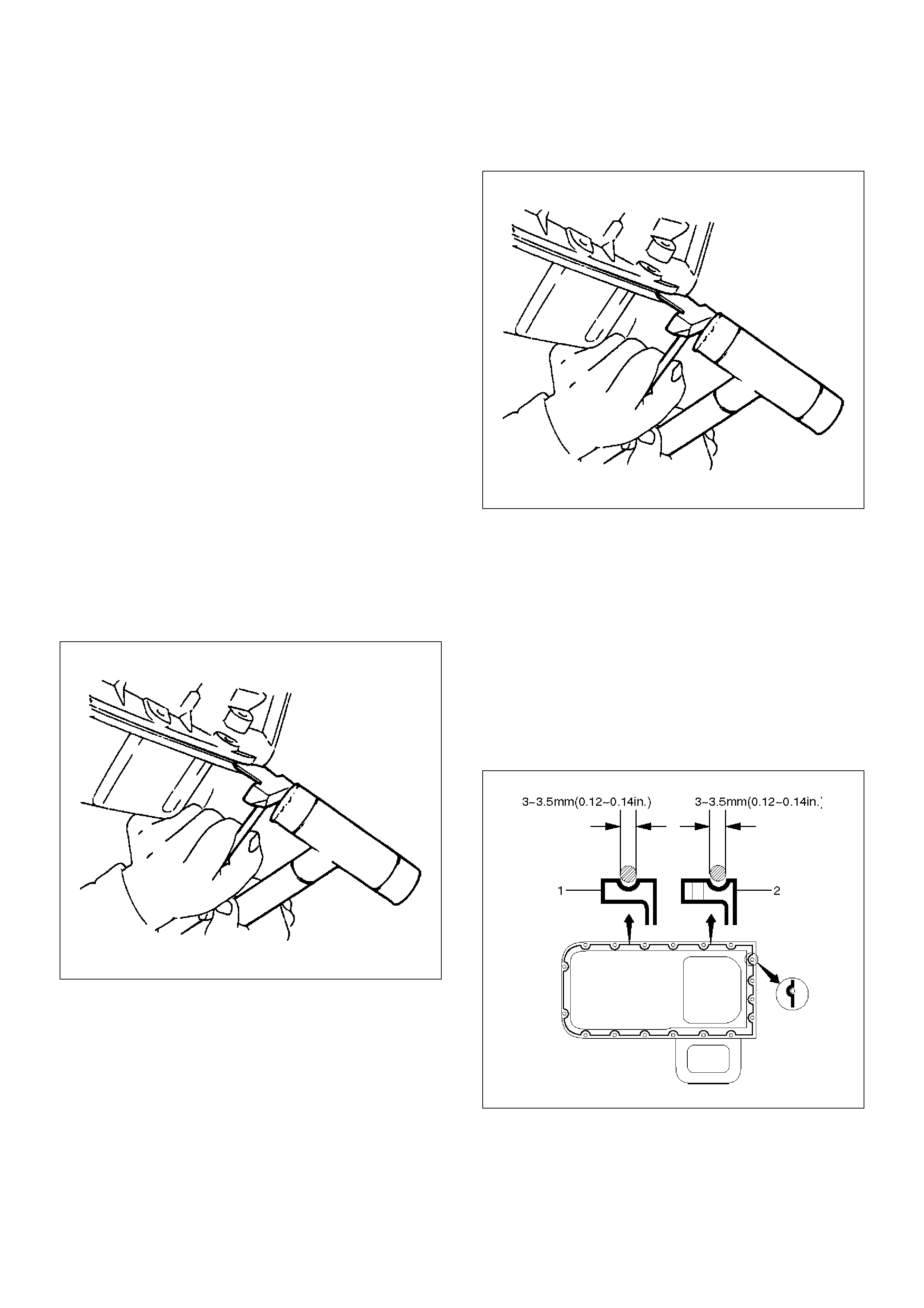
12. Remove oil pan, using 5–8840–2153–0 sealer
cutter, remove oil pan.
013RS003
13. Remove crankcase fixing bolts.
14. Remove crankcase, using 5–8840–2153–0 sealer
cutter, remove crankcase.
NOTE: Do not deform or damage the flange of oil pan
and crankcase.
Replace the oil pan and/or crankcase if deformed or
damaged.
013RS003
Installation
1. Install crankcase.
1. Remove residual sealant, lubricant and moisture
from mounting surface, then dry thoroughly.
2. Properly apply a 4.5 mm (0.7 in) wide bead of
sealant (TB-1207C or equivalent) to mounting
surface of crankcase.
Sealant beat must be continuous.
• The crankcase must be installed within 5
minutes after sealant application before the
sealant hardens.
013RW010
3. Install crankcase, tighten crankcase fixing bolts
to the specified torque.
Torque : 10 N·m (1.0 Kg·m/89 lb in)
013RW004
2. Install oil pan
1. Remove residual sealant, lubricant and moisture
from mounting surface, then dry thoroughly.
2. Properly apply a 4.5 mm (07 in) wide bead of
sealant (TB-1207C or equivalent) to mounting
surface of oil pan.
Sealant beat must be continuous.
• The crankcase must be installed within 5
minutes after sealant application befor the
sealant hardens.
013RW003
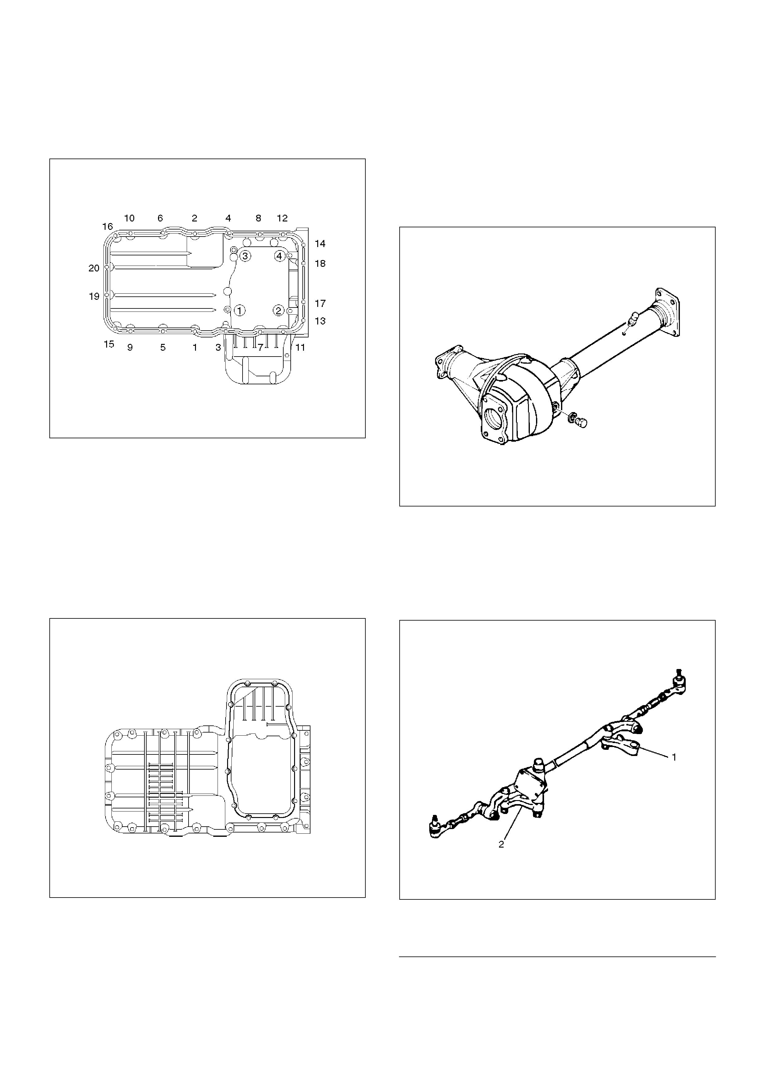
3. Install oil pan, tighten oil pan fixing bolts to the
specified torque.
Torque : 25 N·m (2.5 Kg·m/18 lb ft)
3. Install axle housing assembly and tighten fixing
bolts to the specified torque.
Axle case bolts
Torque : 82 N·m (8.4 Kg·m/60 lb ft)
Mounting bolts
Torque : 152 N·m (15.5 Kg·m/112 lb ft)
013RW005
4. Install relay lever assembly and tighten fixing bolts.
Torque: 44 N·m (4.5 Kg·m/32 lb ft)
5. Engage teeth of pitman arm and steering unit, and
tighten nut to the specified torque.
Torque : 216 N·m (22.0 Kg·m/159 lb ft)
013RW006
EndOFCallout
Legend
(1) Pitman Arm
(2) Relay Lever
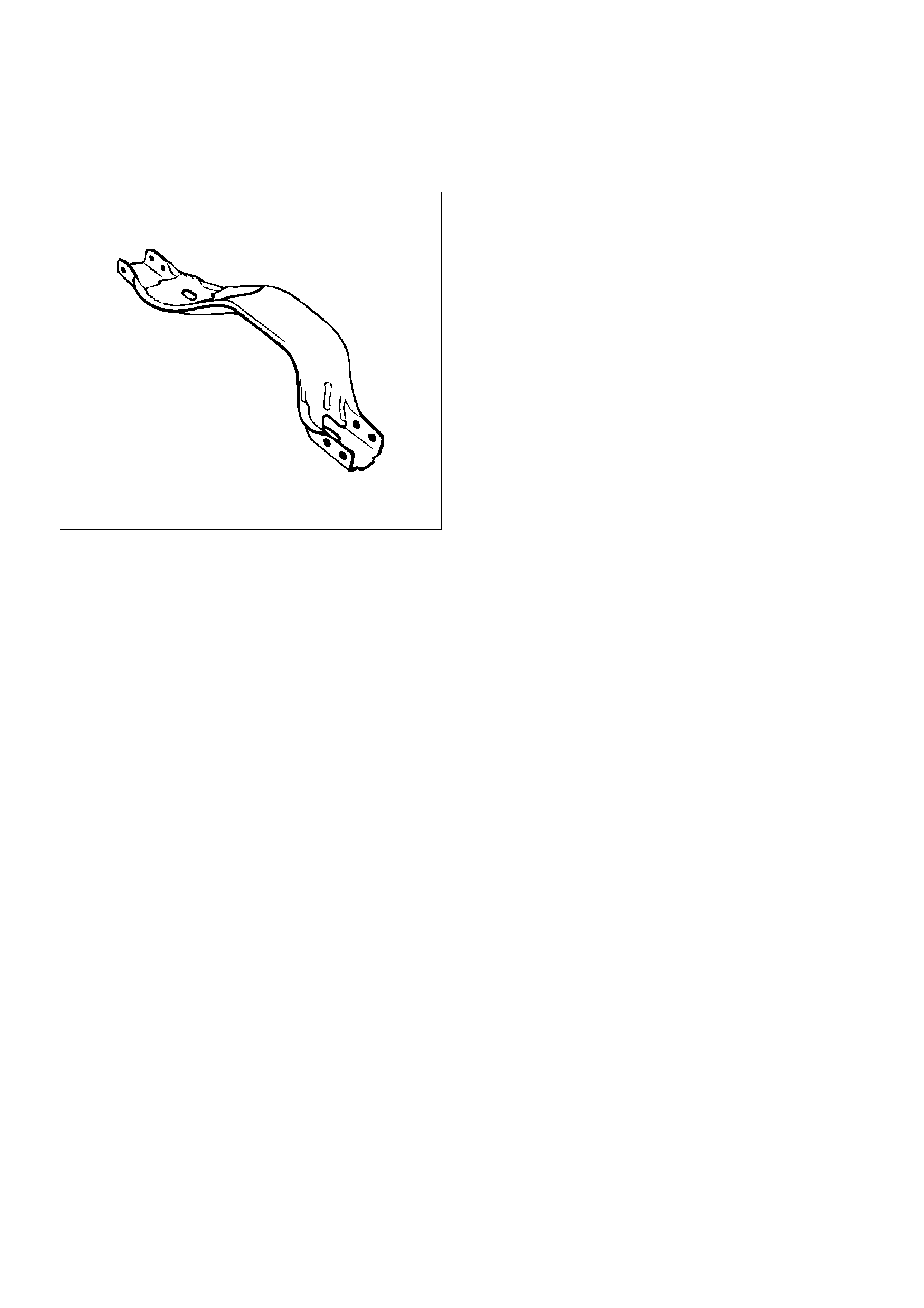
6. Install suspension cross member and tighten fixing
bolts to the specified torque.
Torque : 78 N·m (8.0 Kg·m/58 lb ft)
013RW007
7. Install radiator under fan shroud.
8. Install stone guard.
9. Install engine oil level dipstick.
10. Fill engine oil until full level on engine oil gauge
dipstick.
Oil Pump
Removal
1.Disconnect battery ground cable.
2.Drain engine oil.
3.Remove crankcase assembly.
• Refer to removal procedure for Oil Pan and
Crankcase in this manual.
4.Remove crankshaft pulley.
•Refer to removal procedure for Crankshaft Pulley
in this manual.
5. Remove timing belt.
•Refer to removal procedure for Timing Belt in this
manual.
6. Remove timing pulley from crankshaft.
7. Remove four fixing bolts from oil filter assembly.
8. Remove oil strainer fixing bolts, remove oil strainer
assembly with O-ring.
9. Remove three bolts from oil pipe and O-ring.
10. Remove eight oil pump fixing bolts, then oil pump
assembly.
11. Remove sealant from mounting surface of oil pump
assembly, cylinder block and take care not to
damage mounting surfaces of oil pump and cylinder
block.
Installation
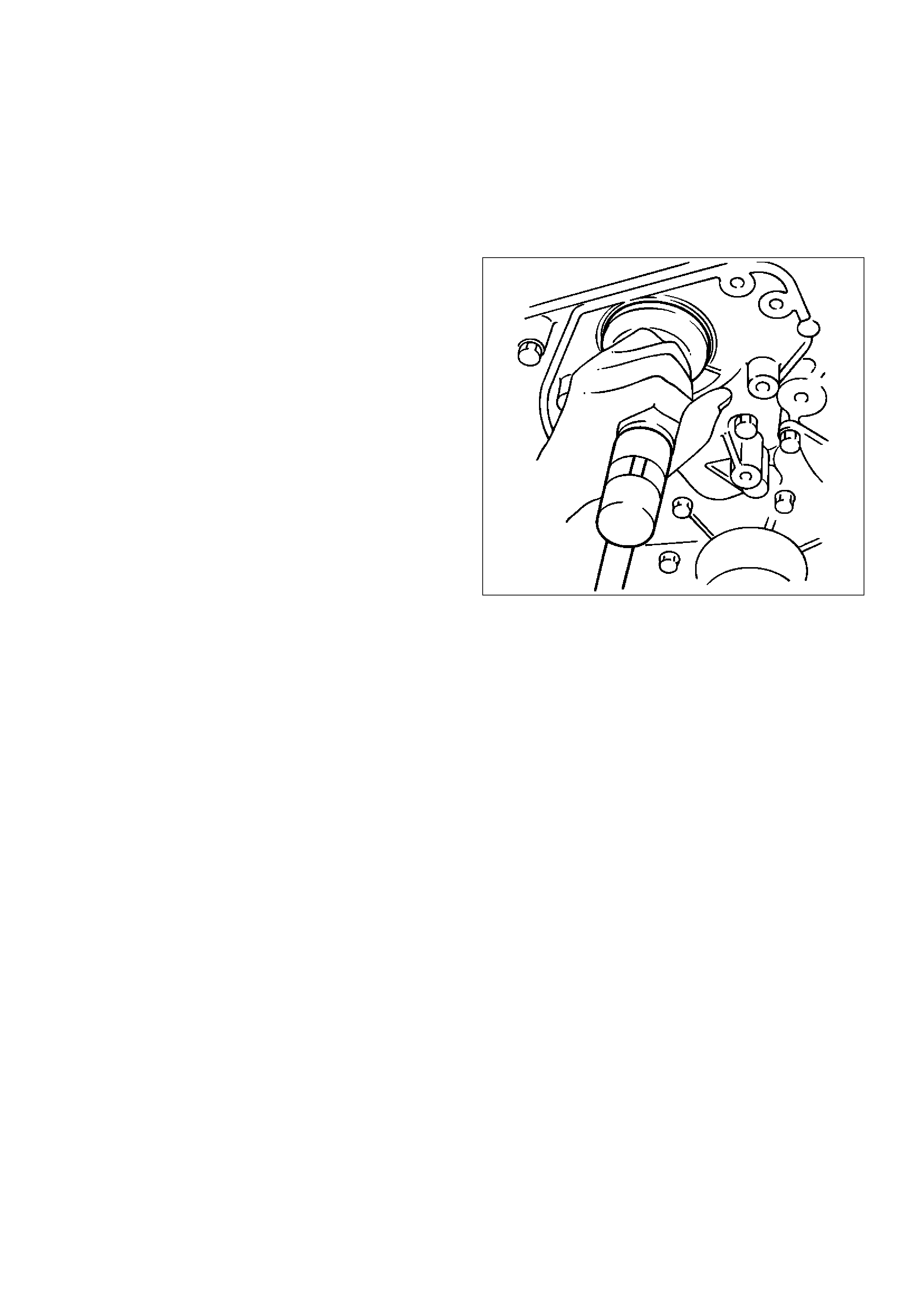
1. Install oil pump assembly
• Apply sealant (TB-1207B or equivalent) to the oil
pump mounting surfaces as shown in the
illustration.
• The oil pump assembly must be installed within 5
minutes after sealant application before the
sealant hardens.
NOTE: Do not apply sealant to the oil ports.
051RW002
• Use 5–8840–2287–0 installer when installing new
oil seal.
• Apply engine oil to oil seal lip.
• Install oil pump assembly to the cylinder block.
NOTE: Do not damage oil seal during installation of oil
pump assembly.
015RS001
• Tighten fixing bolts to the specified torque.
Torque : 25 N·m (2.5 Kg·m/18 lb ft)
051RW001
2. Install oil pipe with O-ring, tighten fixing bolt to the
specified torque.
Torque : 10 N·m (1.0 Kg·m/89 lb in)
3. Install oil strainer with O-ring, tighten fixing bolt to
the specified torque.
Torque : 25 N·m (2.5 Kg·m/18 lb ft)
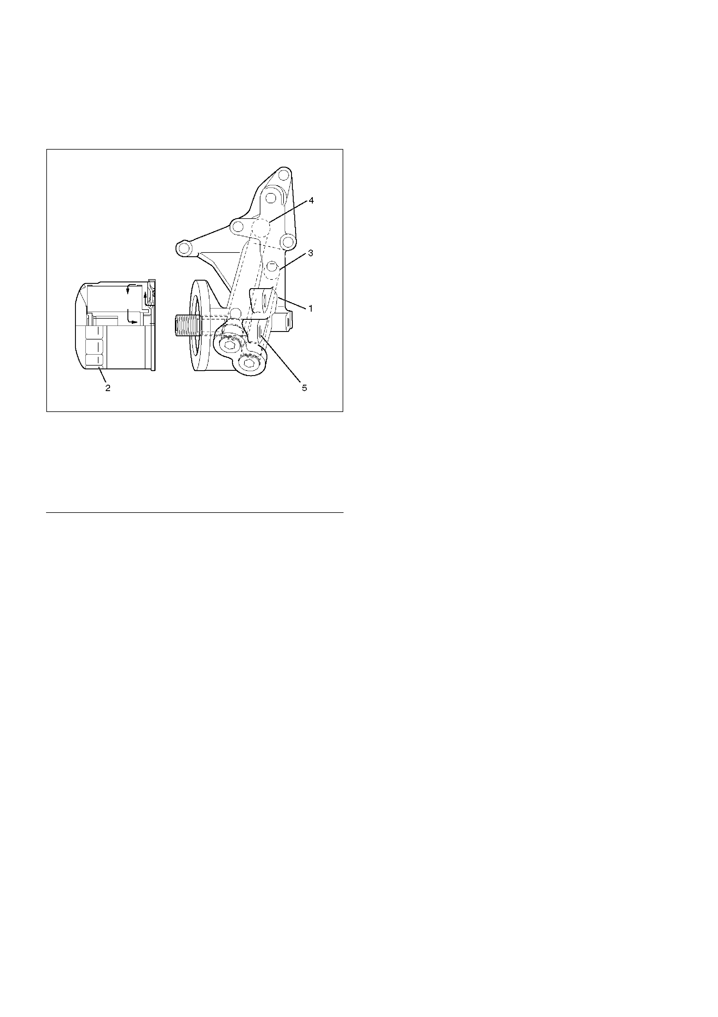
4.Install oil filter assembly and tighten bolts to the
specified torque.
Torque : 25 N·m (2.5 Kg·m/18 lb ft)
050RW001
EndOFCallout
5.Install timing pulley on crankshaft.
Install timing belt.
•Refer to installation procedure for Timing Belt in
this manual.
6.Install crankshaft pulley.
•Refer to install procedure for Crankshaft Pulley in
this manual.
7. Install crankcase assembly.
•Refer to installation procedure for Oil Pan and
Crankcase in this manual.
8. Refill engine oil until full level on engine oil dipstick.
Legend
(1) Oil Pump
(2) Oil Filter
(3) Oil Gallery
(4) From Oil Filter
(5) To Oil Filter
Oil Pump Oil Seal
Removal
1.Disconnect battery ground cable.
2.Drain engine oil.
3.Remove crankshaft pulley.
•Refer to removal procedure for Crankshaft Pulley
in this manual.
4. Remove timing belt.
•Refer to removal procedure for Timing Belt in this
manual.
5. Remove timing pulley from crankshaft.
6. Remove oil pump oil seal using a sealer puller.
NOTE: Take care not to damage sealing surfaces of oil
pump and crankshaft when removing oil seal.
Installation
1. Install oil pump oil seal, apply engine oil to oil seal
lip, then install oil seal using 5–8840–2287–0
installer.
015RS001
2. Install timing pulley to crankshaft.
3. Install timing belt.
•Refer to installation procedure for Timing Belt in
this manual.
4. Install crankshaft pulley.
•Refer to installation procedure for Crankshaft
Pulley in this manual.
5. Refill engine oil until full level.
Oil Filter
Removal
1. Disconnect battery ground cable.
2. Drain engine oil.
3. Remove oil filter using 5-8840-0203-0 filter wrench.
Installation
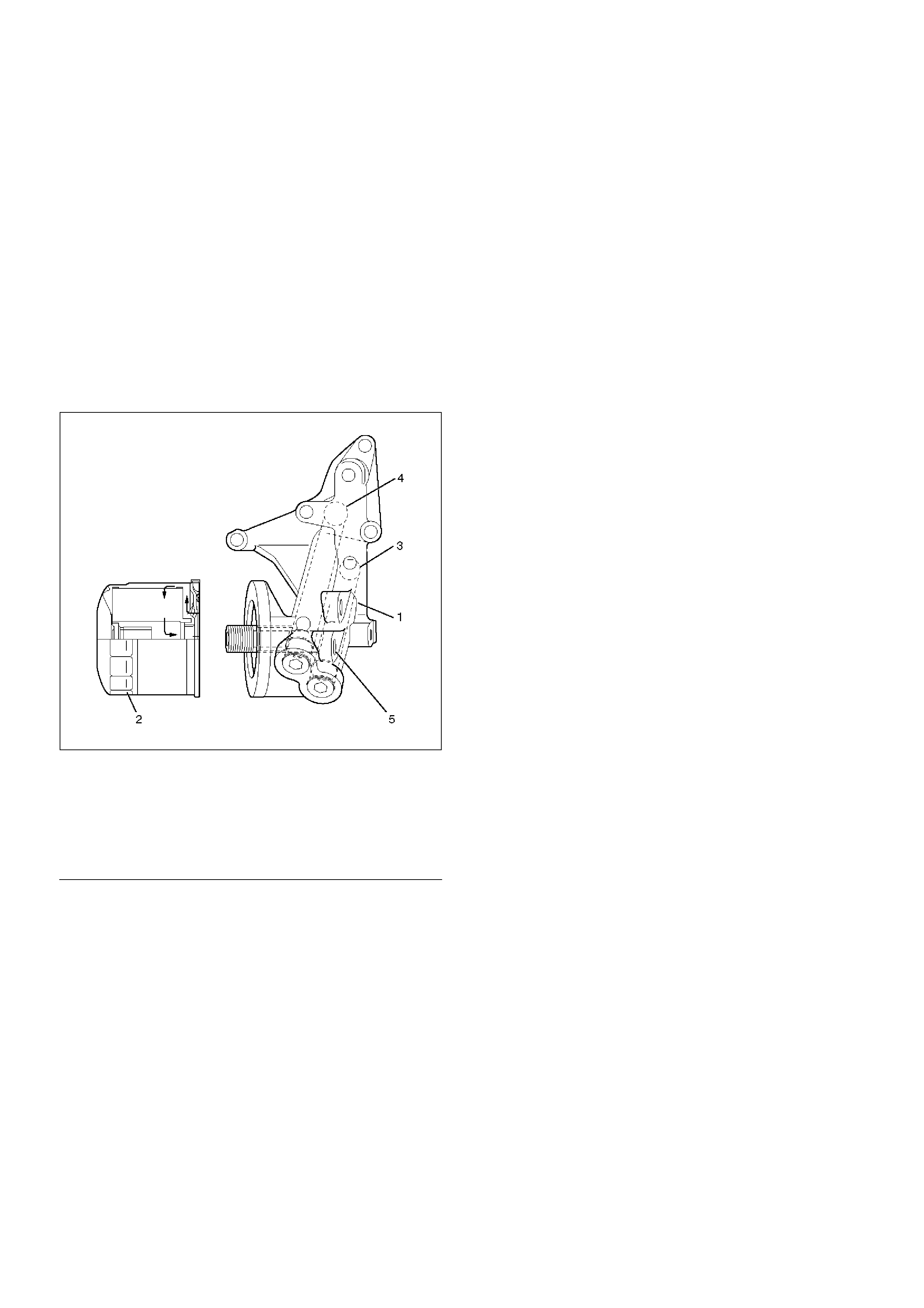
1. Clean filter fitting surface and apply small amount of
engine oil to sealing surface.
2. Install oil filter cartridge by hand until it comes in
contact with sealing surface then rotate additional 2/
3 turn to tighten using 5-8840-0203-0 filter wrench.
050RW001
EndOFCallout
3. Fill engine oil until full level on dipstick.
4. Reconnect battery ground cable.
Legend
(1) Oil Pump
(2) Oil Filter
(3) Oil Gallery
(4) From Filter
(5) To Filter
Main Data and Specification
General Specification
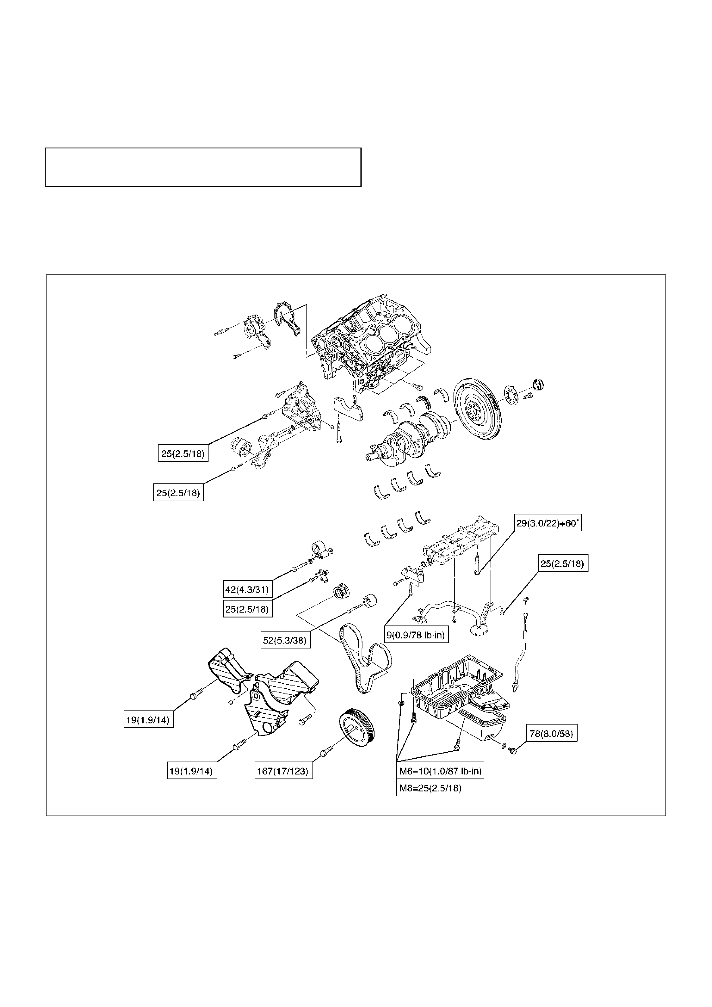
Torque Specifications
Crankcase, Oil pan, Timing belt tensioner, Timing
pulley, timing belt cover, Oil pump, Oil gallery, Oil
strainer N·m (Kg·m/lbft)
E06RW045
Item Specification
Oil capacity - 5.3 liters
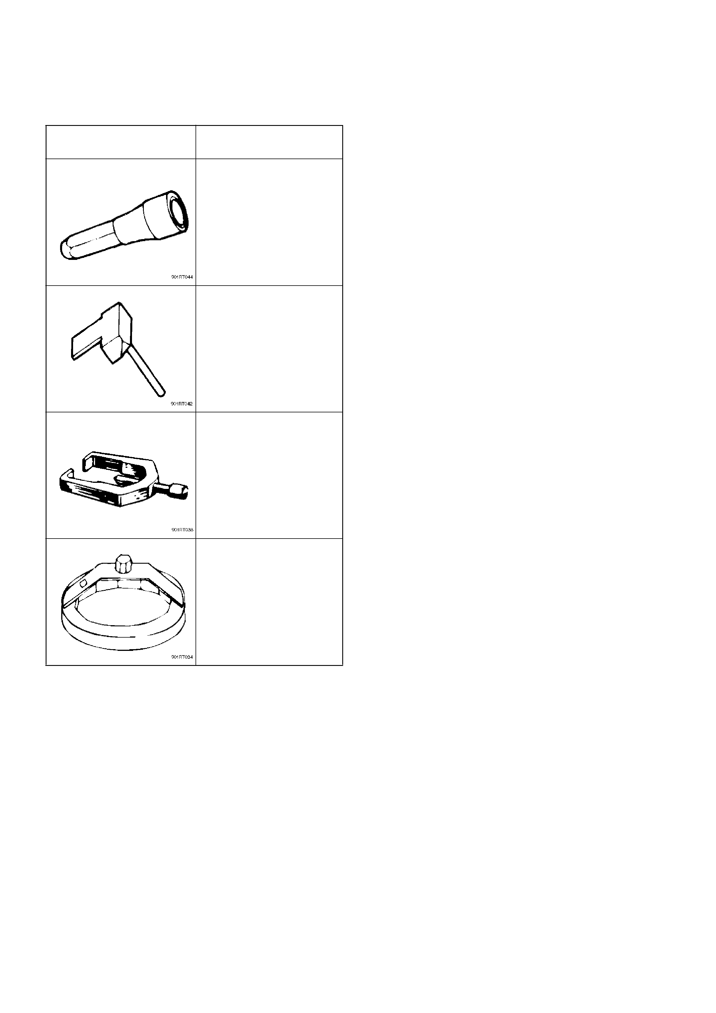
Special Tool
ILLUSTRATION TOOL NO.
TOOL NAME
5–8840–2287–0
(J–39202)
Installer; Oil pump oil seal
5–8840–2153–0
(J–37228)
Seal cutter
5–8840–2005–0
(J–29107)
Universal pitman arm
puller
5–8840–0203–0
(J–36390)
Wrench; Oil filter