
SECTION 6D1 - 3.5L ENGINE DRIVEABILITY AND
EMISSIONS
Specifications
Tightening Specifications
Diagrams and Schematics
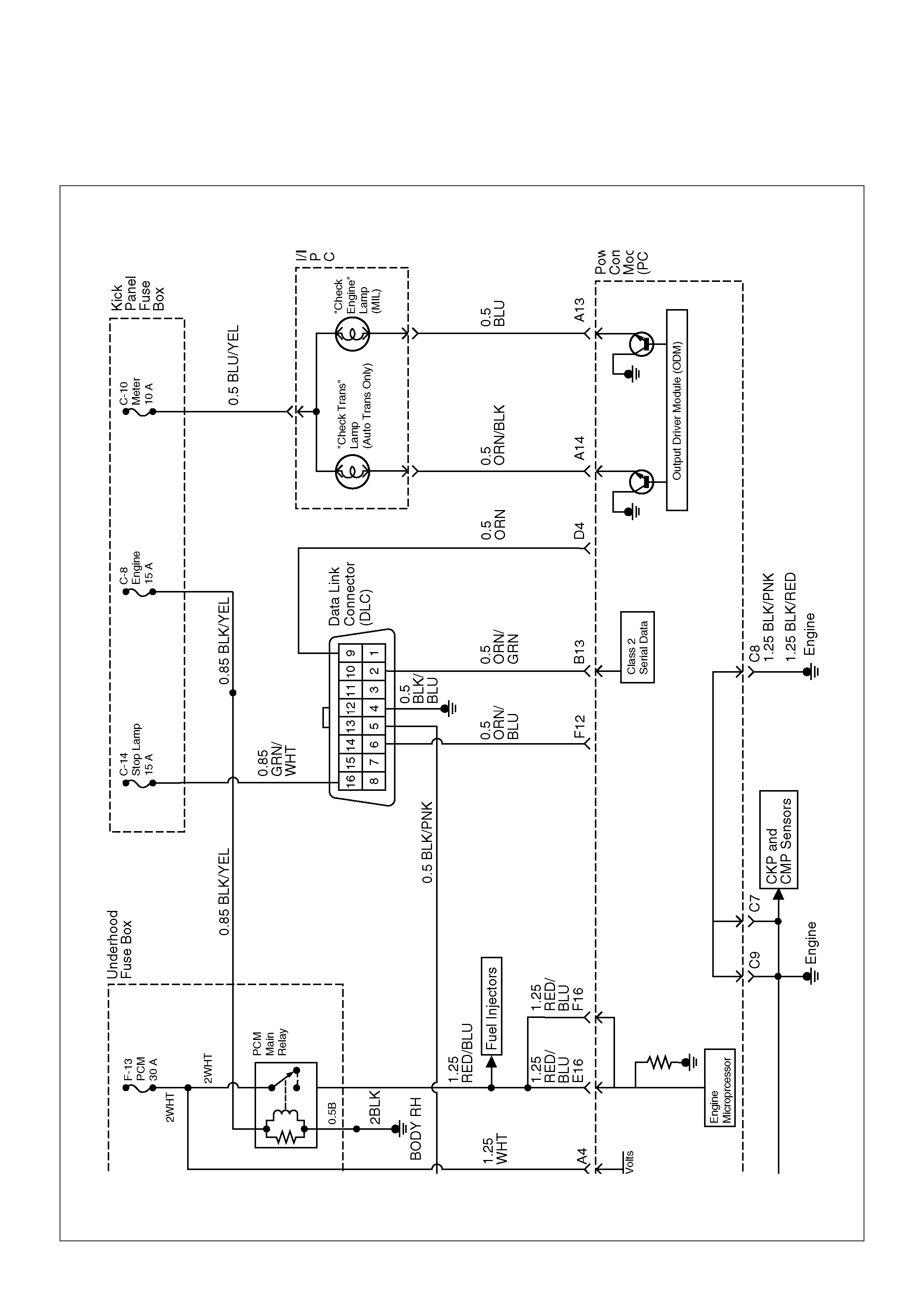
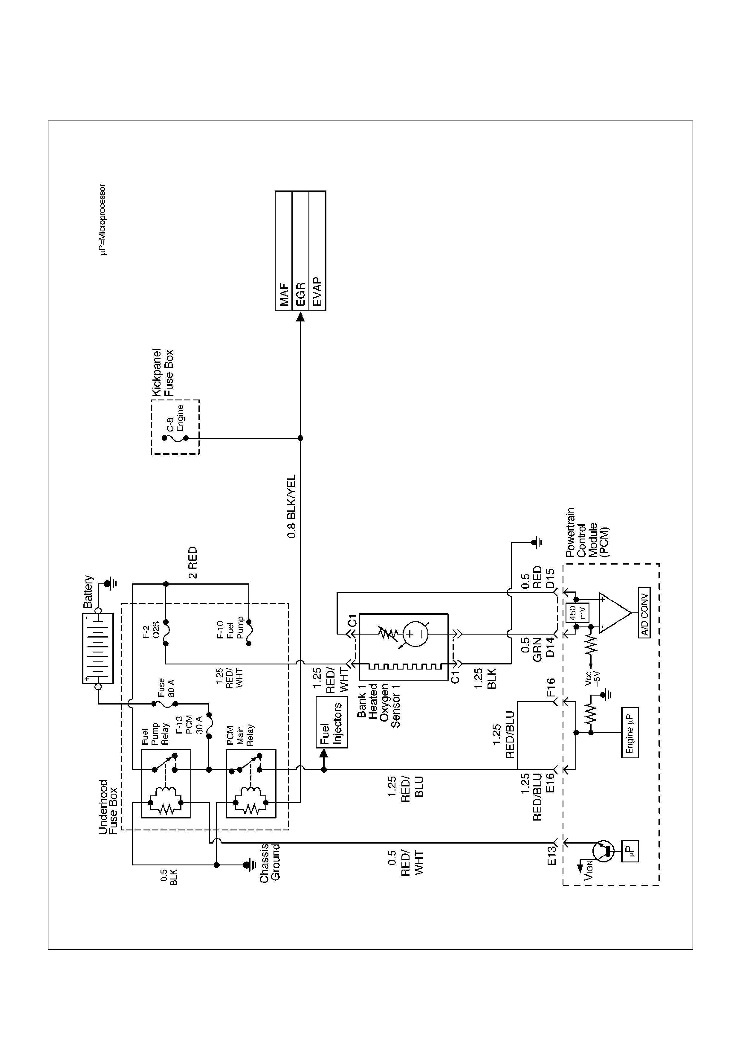
PCM Wiring Diagram (1 of 7)
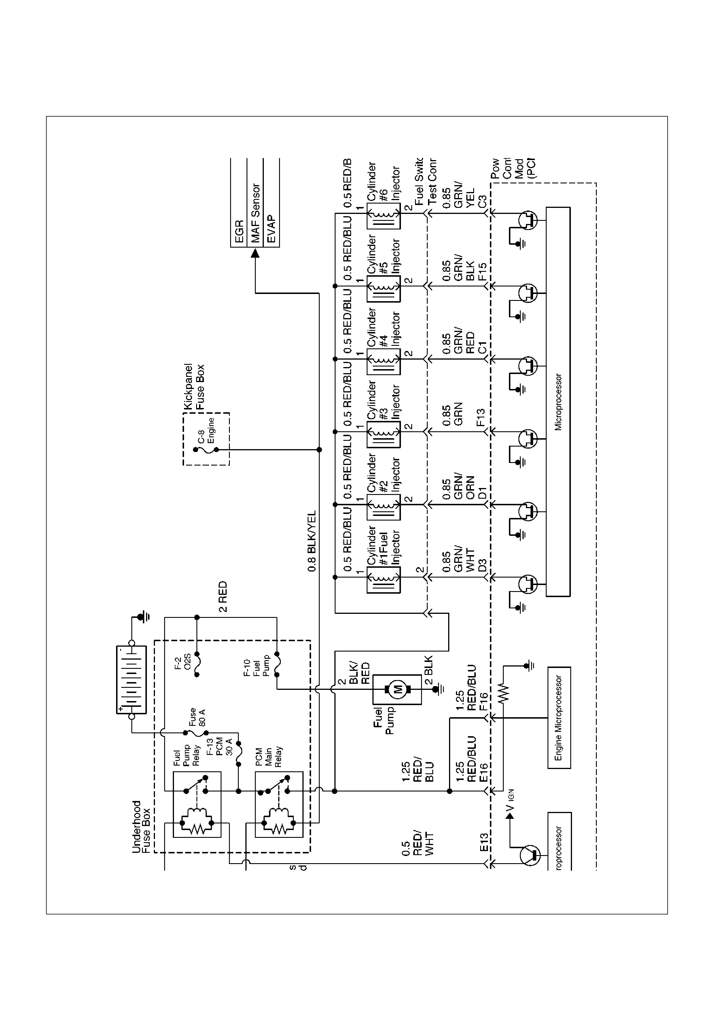
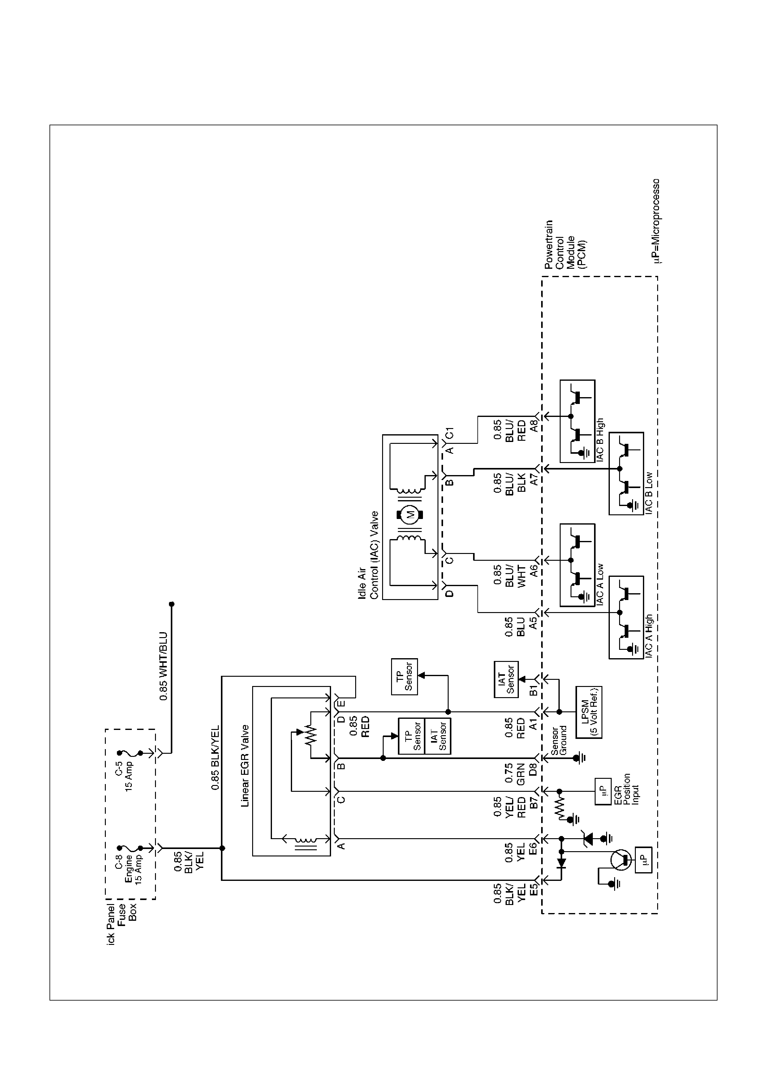
PCM Wiring Diagram (2 of 7)
PCM Wiring Diagram (3 of 7)
PCM Wiring Diagram (4 of 7)
PCM Wiring Diagram (5 of 7)
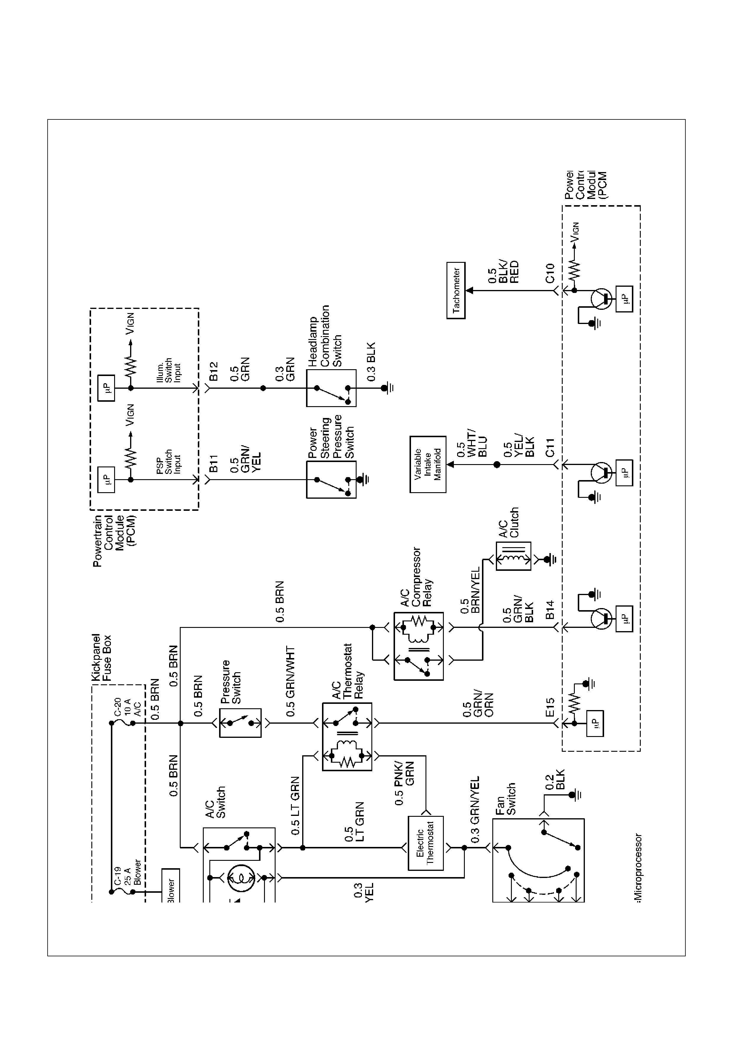
PCM Wiring Diagram (6 of 7)
PCM Wiring Diagram (7 of 7)
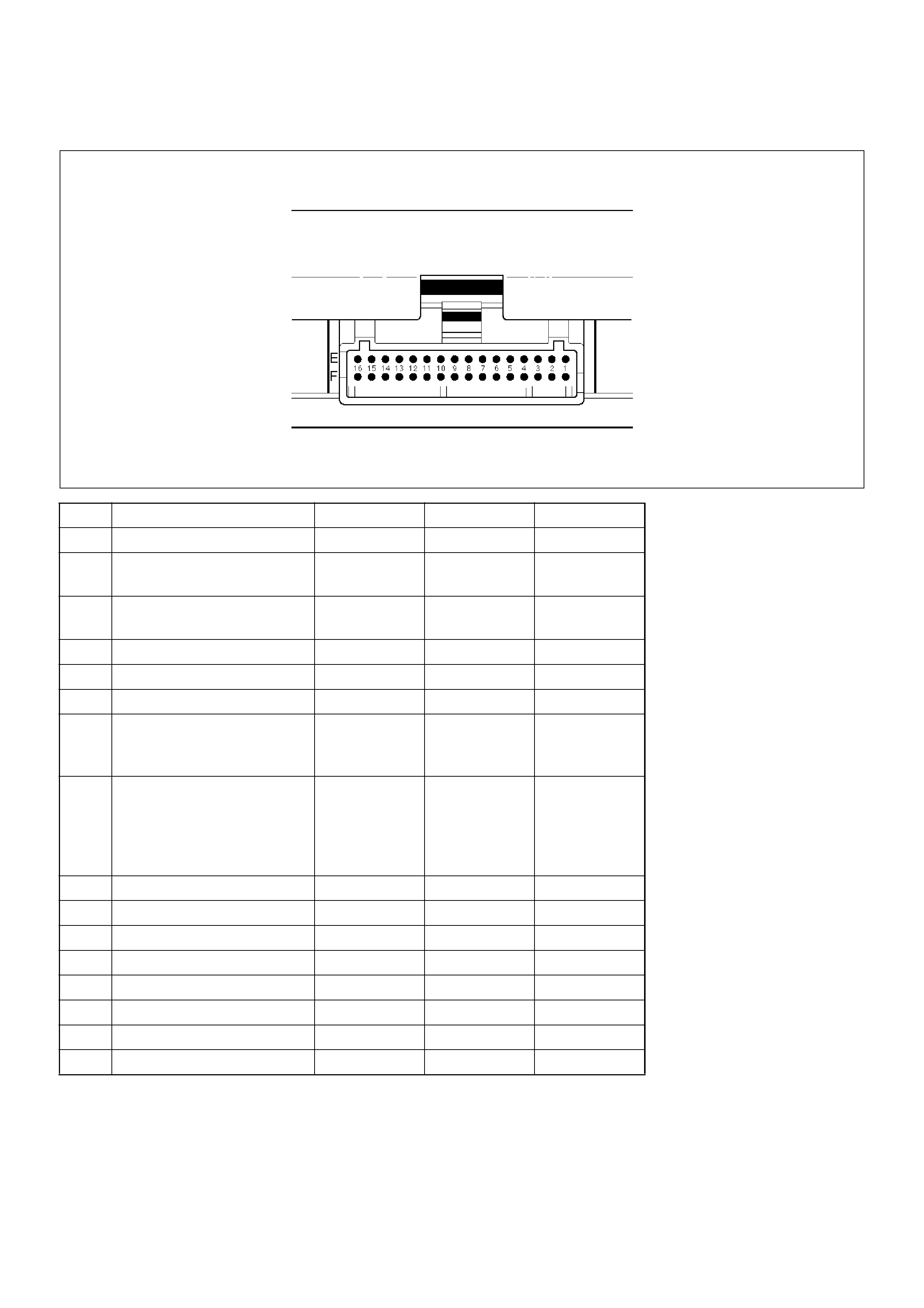
PCM Pinouts
PCM Pinout Table, 32-Way Red Connector –
Row “A”
PCM Pinout Table, 32-Way Red Connector –
Row “B”
PCM Pinout Table, 32-Way White Connector –
Row “C”
PCM Pinout Table, 32-Way White Connector –
Row “D”
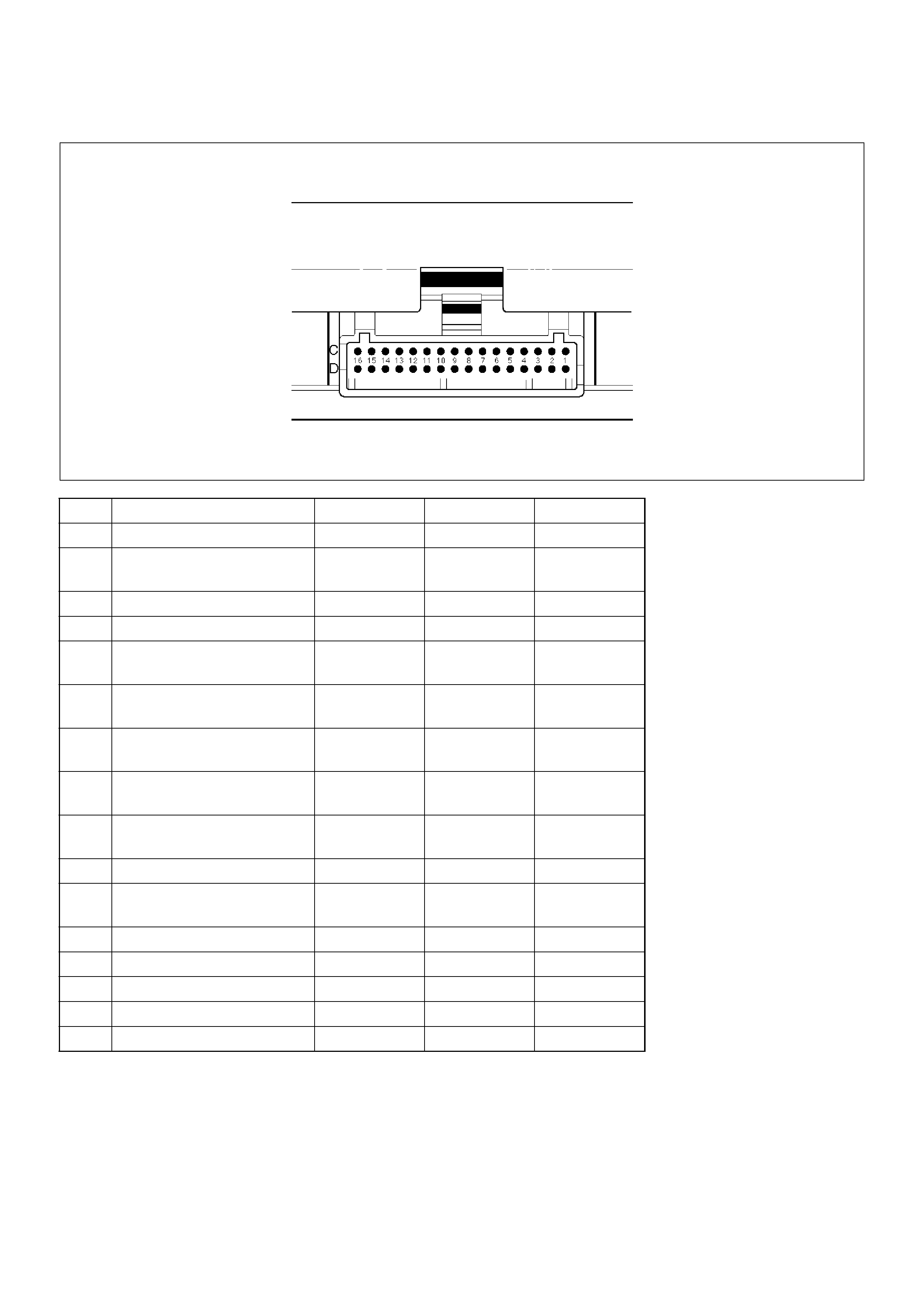
PCM Pinout Table, 32-Way Blue Connector –
Row “E”
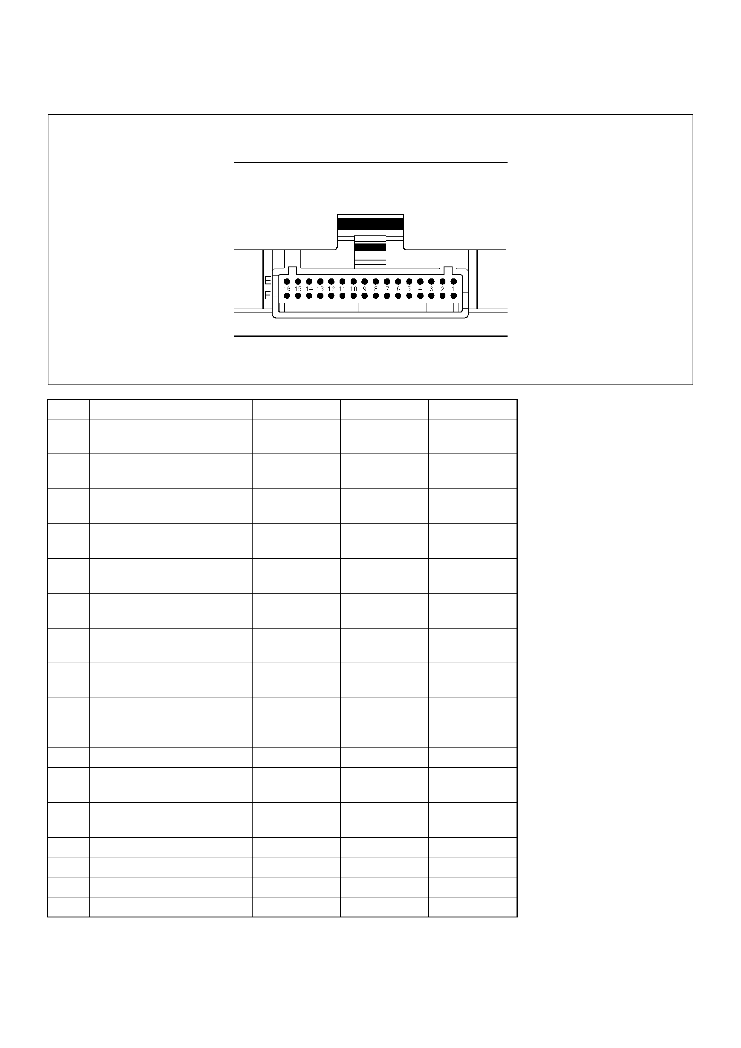
PCM Pinout Table, 32-Way Blue Connector –
Row “F”
Component Locators
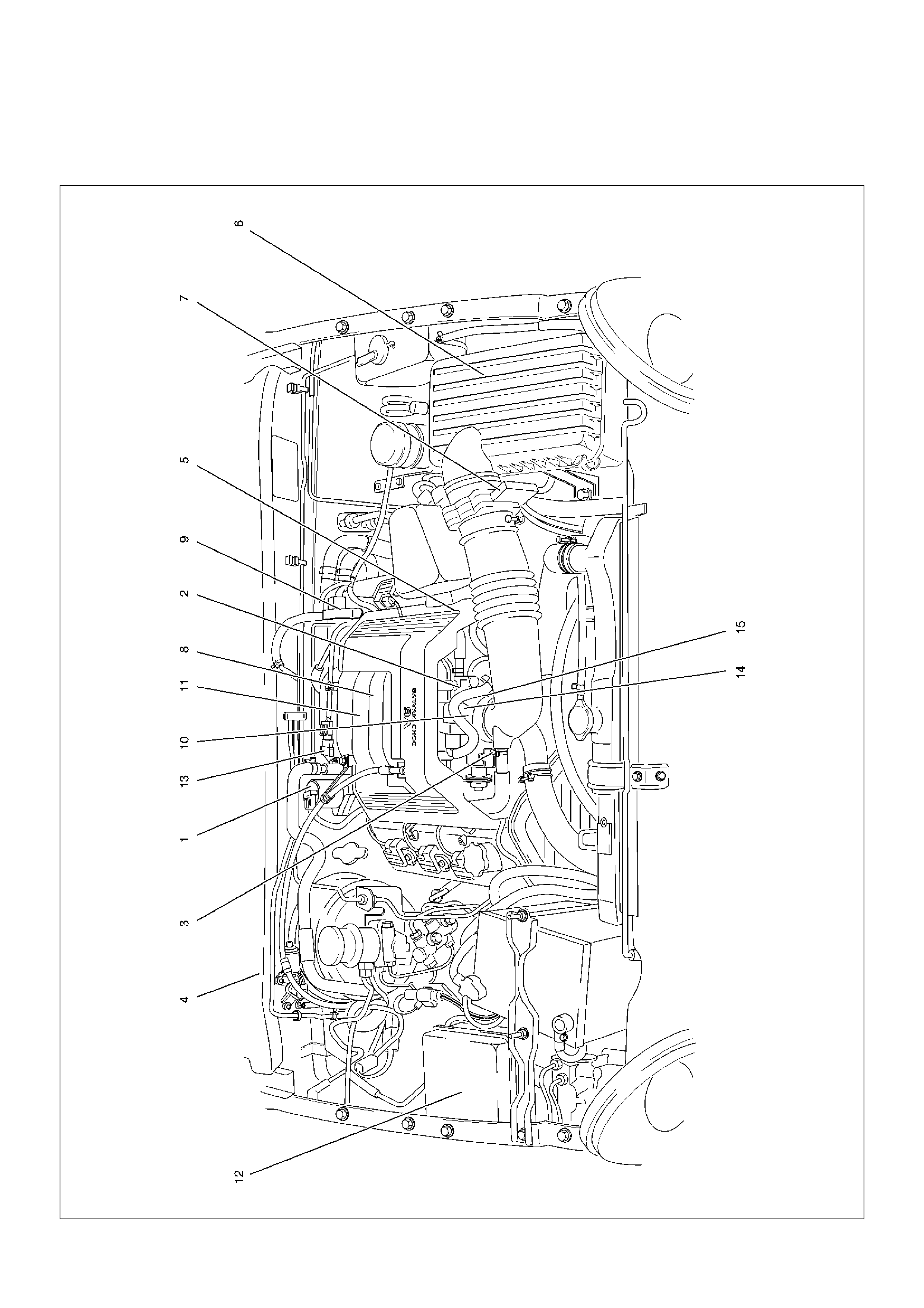
Engine Component Locator
Undercarriage Component Locator
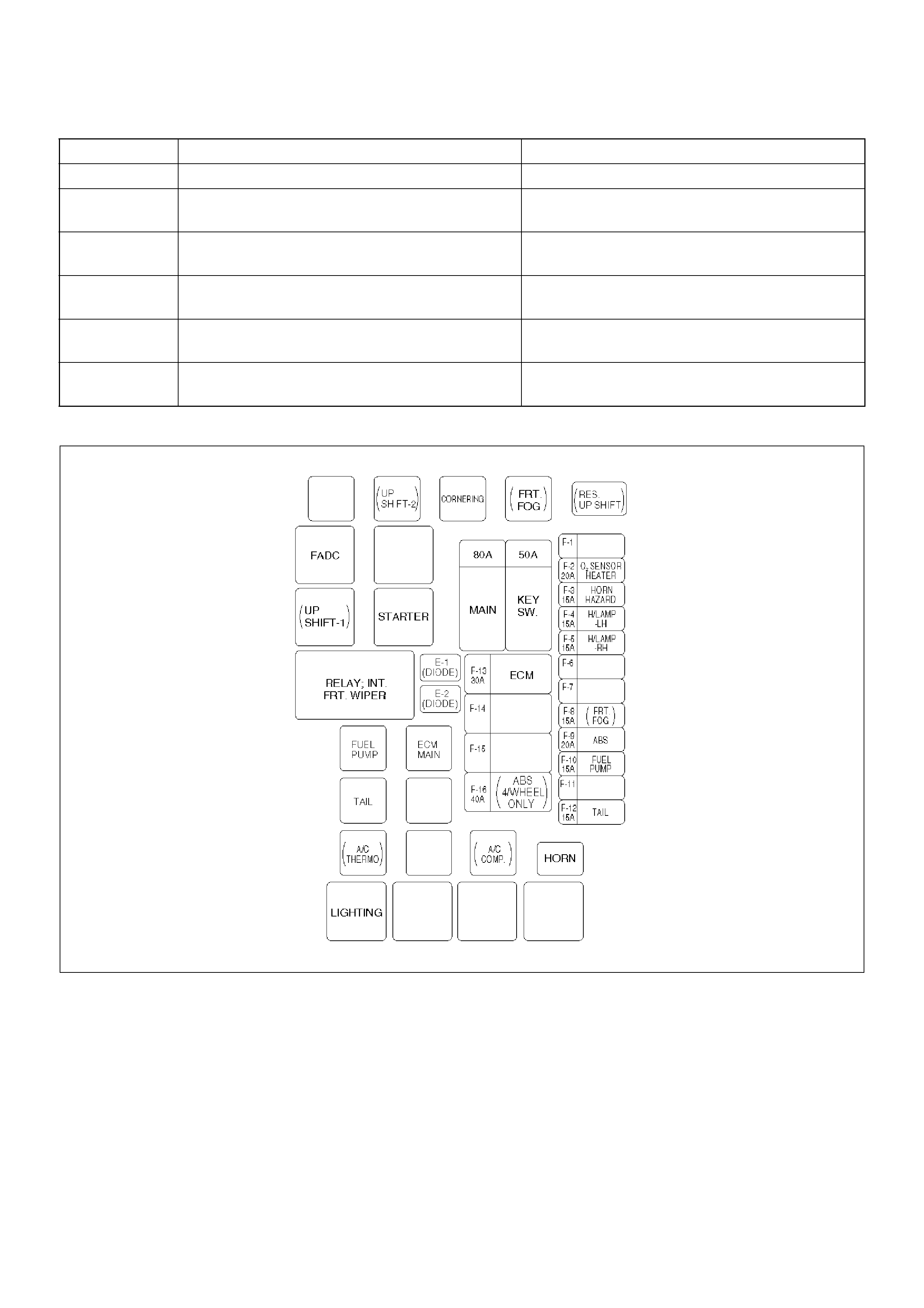
Fuse and Relay Panel (Underhood Electrical Center)
Sensors and Miscellaneous Component Locator
Diagnosis
Strategy-Based Diagnostics
Strategy-Based Diagnostics
DTC Stored
No DTC
No Matching Symptom
Intermittents
No Trouble Found
Verifying Vehicle Repair
General Service Information
OBD Serviceablity Issues
Maintenance Schedule
Visual / Physical Engine Compartment
Inspection
Basic Knowledge of Tools Required
Serial Data Communications
Class II Serial Data Communications
On-Board Diagnostic (OBD)
On-Board Diagnostic Tests
Comprehensive Component Monitor Diagnostic
Operation
Common OBD Terms
The Diagnostic Executive
DTC Types
Verifying Vehicle Repair
Reading Diagnostic Trouble Codes Using A
Tech 2
Using Tech 2 On The Vehicle
Connecting TECH 2 To The Vehicle
Powertrain Application Menu
3.2l V6 6VE1 Engine Functions
Primary System-Based Diagnostic
Primary System-Based Diagnostic
Fuel Control Heated Oxygen Sensor
HO2S Heater
Fuel Trim System Monitor Diagnostic Operation
Fuel Trim System Monitor Diagnostic Operation
Fuel Trim Cell Diagnostic Weights
On-Board Diagnostic (OBD) System Check
A/C Clutch Control Circuit Diagnosis
Electronic Ignition System Diagnosis
Fuel Metering System Check
Idle Air Control (IAC) Valve
Fuel System Pressure Test
Fuel Injector Coil Test Procedure and Fuel Injector
Balance Test Procedure
Injector Coil Test Procedure (Steps 1-6) and Injector
Balance Test Procedure (Steps 7-11)
Knock Sensor Diagnosis
Powertrain Control Module (PCM) Diagnosis
Multiple PCM Information Sensor DTCS Set
Exhaust Gas Recirculation (EGR) Diagnosis
Engine Tech 2 Data Definitions and Ranges
Typical Scan Data Values
No Malfunction Indicator Lamp (MIL)
Malfunction Indicator Lamp (MIL) “ON”Steady
Engine Cranks But Will Not Run
Fuel System Electrical Test
Fuel System Diagnosis
Idle Air Control (IAC) System Check
Knock Sensor (KS) System Check (Engine Knock, Poor
Performance, or Poor Economy)
Exhaust Gas Recirculation (EGR) System Check
Manifold Absolute Pressure (MAP) Output Check

PCM Diagnostic Trouble Codes
Diagnostic Trouble Code (DTC) P0101 MAF
System Performance
Diagnostic Trouble Code (DTC) P0102 MAF
Sensor Circuit Low Frequency
Diagnostic Trouble Code (DTC) P0103 MAF
Sensor Circuit High Frequency
Diagnostic Trouble Code (DTC) P0107 MAP
Sensor Circuit Low Voltage
Diagnostic Trouble Code (DTC) P0108 MAP
Sensor Circuit High Voltage
Diagnostic Trouble Code (DTC) P0112 IAT
Sensor Circuit Low Voltage
Diagnostic Trouble Code (DTC) P0113 IAT
Sensor Circuit High Voltage
Diagnostic Trouble Code (DTC) P0117 ECT
Sensor Circuit Low Voltage
Diagnostic Trouble Code (DTC) P0118 ECT
Sensor Circuit High Voltage
Diagnostic Trouble Code (DTC) P0121 TP
System Performance
Diagnostic Trouble Code (DTC) P0122 TP
Sensor Circuit Low Voltage
Diagnostic Trouble Code (DTC) P0123 TP
Sensor Circuit High Voltage
Diagnostic Trouble Code (DTC) P0131
HO2S Circuit Low Voltage Bank 1 Sensor 1
Diagnostic Trouble Code (DTC) P0132 HO2S
Circuit High Voltage Bank 1 Sensor 1
Diagnostic Trouble Code (DTC) P0134 HO2S
Circuit Insufficient Activity Bank 1 Sensor 1
Diagnostic Trouble Code (DTC) P0151 HO2S
Circuit Low Voltage Bank 2 Sensor 1
Diagnostic Trouble Code (DTC) P0152 HO2S
Circuit HIGH Voltage Bank 2 Sensor 1
Diagnostic Trouble Code (DTC) P0171 Fuel
Trim System Lean Bank 1
Diagnostic Trouble Code (DTC) P0172 Fuel
Trim System Rich Bank 1
Diagnostic Trouble Code (DTC) P0174 Fuel
Trim System Lean Bank 2
Diagnostic Trouble Code (DTC) P0175 Fuel
Trim System Rich Bank 2
Diagnostic Trouble Code (DTC) P0201
Injector 1 Control Circuit
Diagnostic Trouble Code (DTC) P0202
Injector 2 Control Circuit
Diagnostic Trouble Code (DTC) P0203
Injector 3 Control Circuit
Diagnostic Trouble Code (DTC) P0204
Injector 4 Control Circuit
Diagnostic Trouble Code (DTC) P0205
Injector 5 Control Circuit
Diagnostic Trouble Code (DTC) P0206
Injector 6 Control Circuit
Diagnostic Trouble Code (DTC) P0325
KS Module Circuit
Diagnostic Trouble Code (DTC) P0327
KS Sensor Circuit
Diagnostic Trouble Code (DTC) P0336
58X Reference Signal Circuit
Diagnostic Trouble Code (DTC) P0337
CKP Sensor Circuit Low Frequency
Diagnostic Trouble Code (DTC) P0341
CMP Sensor Circuit Performance
Diagnostic Trouble Code (DTC) P0342
CMP Sensor Circuit Low
Diagnostic Trouble Code (DTC) P0351
Ignition 1 Control Circuit
Diagnostic Trouble Code (DTC) P0352
Ignition 2 Control Circuit
Diagnostic Trouble Code (DTC) P0353
Ignition 3 Control Circuit
Diagnostic Trouble Code (DTC) P0354
Ignition 4 Control Circuit
Diagnostic Trouble Code (DTC) P0355
Ignition 5 Control Circuit
Diagnostic Trouble Code (DTC) P0356
Ignition 6 Control Circuit
Diagnostic Trouble Code (DTC) P0402
EGR Pintle Crank Error
Diagnostic Trouble Code (DTC) P0404
EGR Open Stuck
Diagnostic Trouble Code (DTC) P0405
EGR Low Voltage
Diagnostic Trouble Code (DTC) P0406
EGR High Voltage
Diagnostic Trouble Code (DTC) P0502
VSS Circuit Low Input
Diagnostic Trouble Code (DTC) P0562
System Voltage Low
Diagnostic Trouble Code (DTC) P0563
System Voltage High
Diagnostic Trouble Code (DTC) P0601
PCM Memory
Diagnostic Trouble Code (DTC) P1154 HO2S
Circuit Transition Time Ratio Bank 2 Sensor 1
Diagnostic Trouble Code (DTC) P1171
Fuel System Lean During Acceleration
Diagnostic Trouble Code (DTC) P1380
ABS Rough Road ABS System Fault
Diagnostic Trouble Code (DTC) P1404
EGR Closed Stuck
Diagnostic Trouble Code (DTC) P1508
IAC System Low RPM
Diagnostic Trouble Code (DTC) P1509
IAC System High RPM
Diagnostic Trouble Code (DTC) P1618
Serial Peripheral Interface (SPI) PCM
Interprocessor Communication Error
Diagnostic Trouble Code (DTC) P1625
PCM Unexpected Reset
Diagnostic Trouble Code (DTC) P1626 -
No Response From Immobiliser
Diagnostic Trouble Code (DTC) P1631 -
Received Response Was Not Correct
Diagnostic Trouble Code (DTC) P1640
Driver-1-Input High Voltage

Diagnostic Trouble Code (DTC) P1648 -
Received Incorrect Security Code
Diagnostic Trouble code (DTC) P1649 - Security
Code & Security Key Not Programmed
Symptom Diagnosis
Hard Start Symptom
Surges and/or Chuggles Symptom
Lack of Power, Sluggish or Spongy Symptom
Detonation/Spark Knock Symptom
Rough, Unstable, or Incorrect Idle, Stalling Symptom
Poor Fuel Economy Symptom
Excessive Exhaust Emissions or Odors Symptom
Dieseling, Run-On Symptom
Backfire Symptom
Cuts Out, Misses Symptom
Hesitation, Sag, Stumble Symptom
Default Matrix Table
Camshaft Position (CMP) Sensor
Crankshaft Position (CKP) Sensor
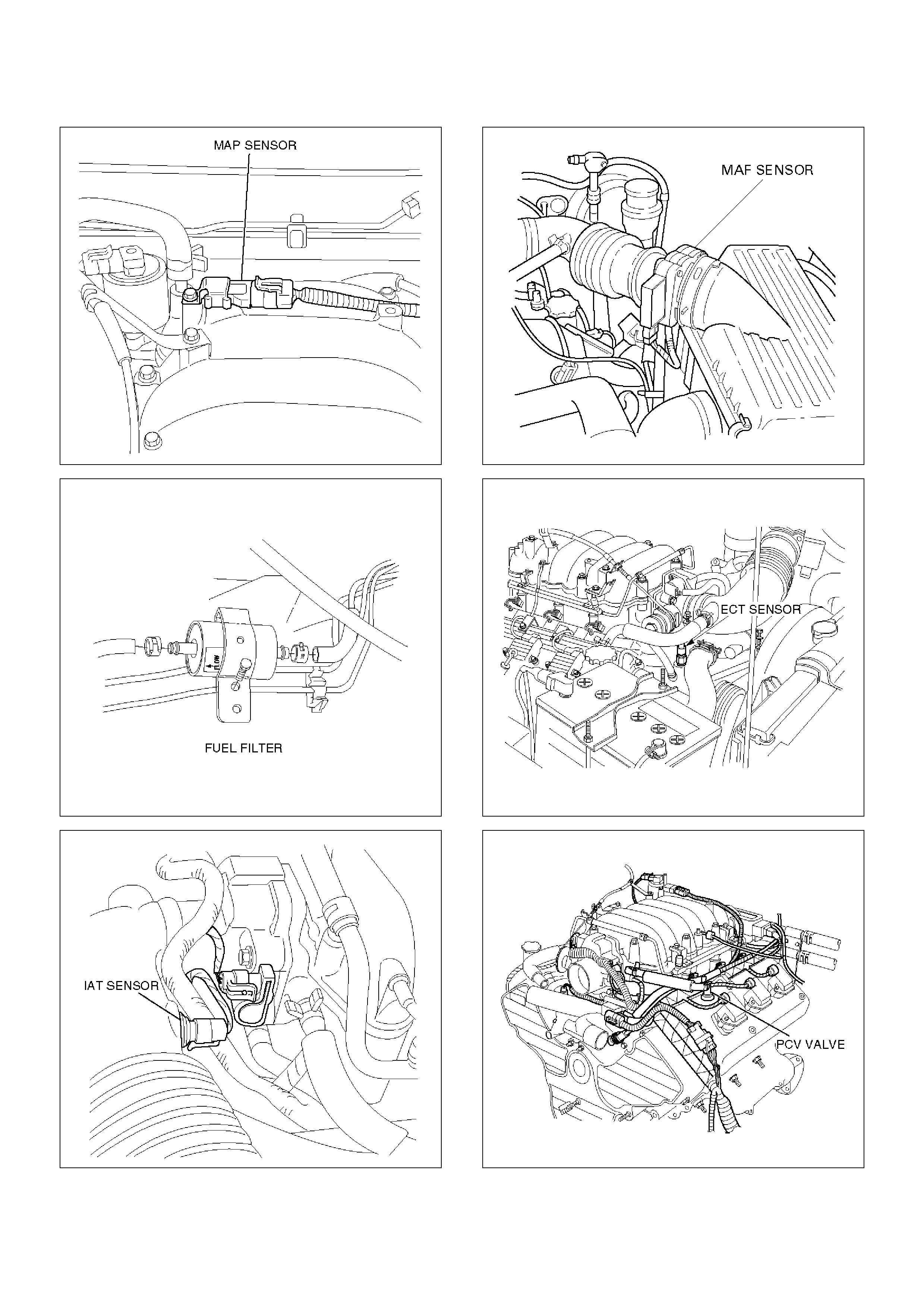
Engine Coolant Temperature (ECT) Sensor
Heated Oxygen Sensor (HO2S)
Intake Air Temperature (IAT) Sensor
Knock Sensor (KS)
Mass Air Flow (MAF) Sensor
Manifold Absolute Pressure (MAP) Sensor
Malfunction Indicator Lamp (MIL)
Powertrain Control Module (PCM)
Electrostatic Discharge (ESD) Damage
EEPROM
Power Steering Pressure (PSP) Switch
Throttle Position (TP) Sensor
Vehicle Speed Sensor (VSS)
Air Cleaner/Air Filter
Idle Air Control (IAC) Valve
Common Chamber
Accelerator Cable Assembly
Accelerator Pedal Replacement
Fuel Filter Cap
Fuel Filter
Fuel Gauge Unit
Fuel Injectors
Fuel Pressure Regulator
Fuel Metering System
Fuel Pump Assembly
Fuel Pump Relay
Fuel Rail Assembly
Fuel Tank
Throttle Body (TB)
Electronic Ignition System
Catalytic Converter
Air Conditioning Relay
EVAP Canister Hoses
EVAP Canister
EVAP Canister Purge Solenoid
Fuel Tank Vent Valve
Linear Exhaust Gas Recirculation (EGR) Valve
Positive Crankcase Ventilation (PCV) Valve
Wiring and Connectors
PCM Connectors and Terminals
Wire Harness Repair: Twisted Shielded Cable
Twisted Leads
Weather-Pack Connector
Com-Pack III
Metri-Pack
General Description (PCM and Sensors)
58X Reference PCM Input
A/C Request Signal
Crankshaft Position (CKP) Sensor
Camshaft Position (CMP) Sensor and Signal
Engine Coolant Temperature (ECT) Sensor
Electrically Erasable Programmable Read Only
Memory (EEPROM)
Fuel Control Heated Oxygen Sensors
Intake Air Temperature (IAT) Sensor
Knock Sensor
Linear Exhaust Gas Recirculation (EGR) Control
Mass Air Flow (MAF) Sensor
Manifold Absolute Pressure (MAP) Sensor
Powertrain Control Module (PCM)
PCM Function
PCM Components
PCM Voltage Description
PCM Input/Outputs
PCM Service Precautions
Reprogramming The PCM
Throttle Position (TP) Sensor
Transmission Fluid Temperature (TFT) Sensor
Transmission Range Switch
Vehicle Speed Sensor (VSS)
Use of Circuit Testing Tools
Aftermarket Electrical and Vacuum Equipment
Electrostatic Discharge Damage
Upshift Lamp
General Description (Air Induction)
Air Induction System
General Description (Fuel Metering)
Acceleration Mode
Accelerator Controls
Battery Voltage Correction Mode
CMP Signal
Clear Flood Mode
Deceleration Mode
Engine Speed Fuel Disable Mode
Fuel Cutoff Mode
Fuel Injector
Fuel Metering System Components
Fuel Metering System Purpose
Fuel Pressure Regulator
Fuel Pump Electrical Circuit
Fuel Rail
Idle Air Control (IAC) Valve
Run Mode
Starting Mode
Throttle Body Unit

General Description (Electronic Ignition System)
Camshaft Position (CMP) Sensor
Crankshaft Position (CKP) Sensor
Ignition Coils
Ignition Control
Ignition Control PCM Output
Knock Sensor (KS) PCM Input
Powertrain Control Module (PCM)
Spark Plug
A/C Clutch Diagnosis
A/C Clutch Circuit Operation
A/C Clutch Circuit Purpose
A/C Request Signal
General Description (Exhaust Gas Recirculation
(EGR) System)
EGR Purpose
Linear EGR Valve
Linear EGR Control
Linear EGR Valve Operation and Results of
Incorrect Operation
EGR Pintle Position Sensor
General Description (Positive Crankcase
Ventilation (PCV) System)
Crankcase Ventilation System Purpose
Crankcase Ventilation System Operation
Special Tools

Specifications
Tightening Specifications
Application N·m Lb Ft. Lb In.
Camshaft Position Sensor Retaining Screw 9 — 78
Crankshaft Position Sensor Mounting Bolt 10 — 87
EGR Bolt 28 21 —
EGR Nut 28 21 —
Engine Coolant Temperature Sensor 20 7.7 —
Fuel Drain Plug 29 22 —
Fuel Pressure Regulator Attaching Screw 6.5 — 60
Fuel Rail Bolts 25 18 —
Fuel Tank Undercover Retaining Bolts 36 27 —
Heated Oxygen Sensor 42 31 —
Lower Intake Manifold to Engine Block Bolts 25 18 —
Lower Intake Manifold to Engine Block Nuts 25 18 —
Spark Plugs 18 13 —
Throttle Body Mounting Bolts 25 18 —
Upper Intake Manifold to Lower Intake Manifold Bolts 25 18 —
VSS Retaining Bolt 13 — 120
Diagrams and Schematics
PCM Wiring Diagram (1 of 7)
D06RW00005
PCM Wiring Diagram (2 of 7)
D06RW134
D06RW140
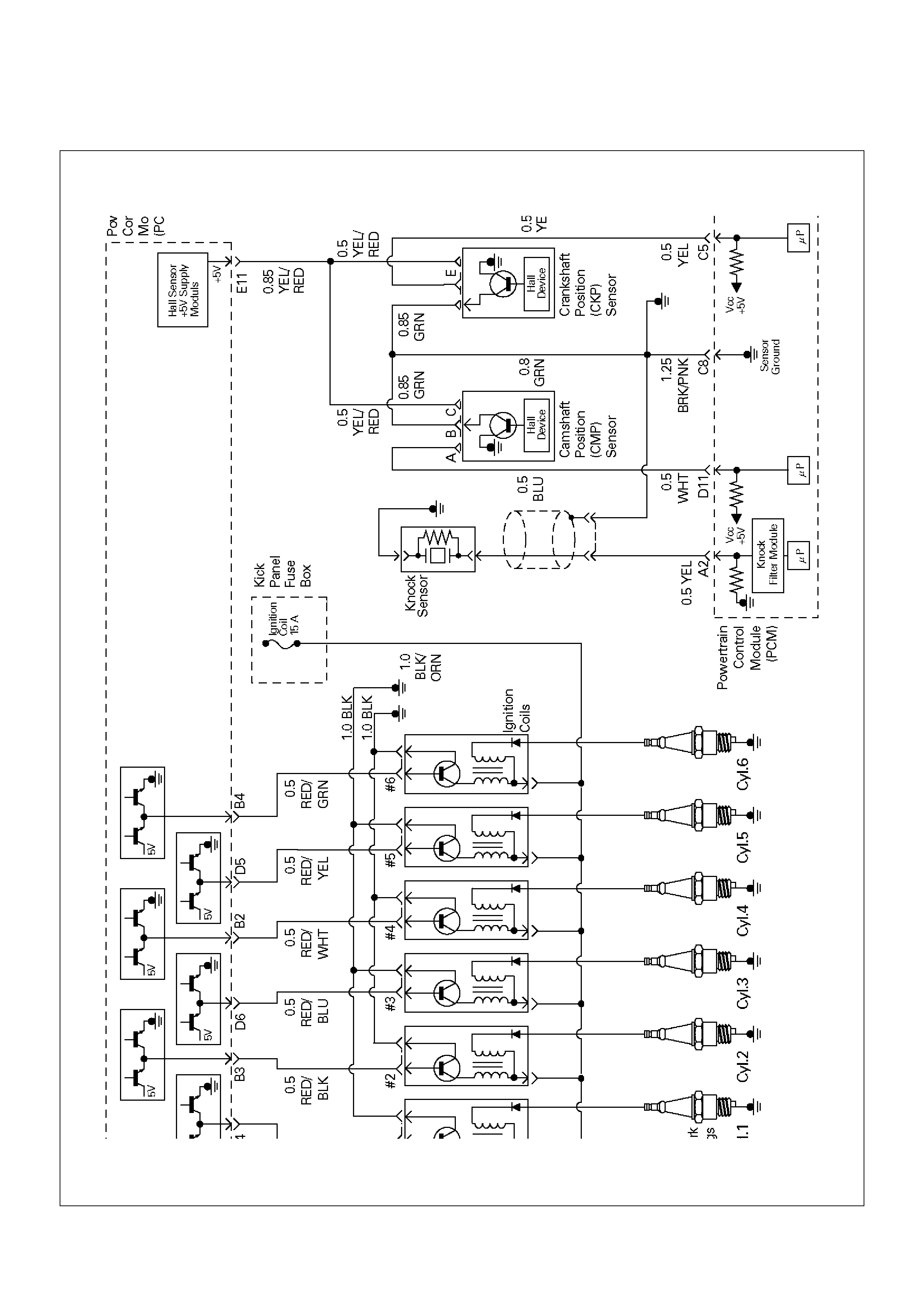
PCM Wiring Diagram (3 of 7)
D06RX0 0003
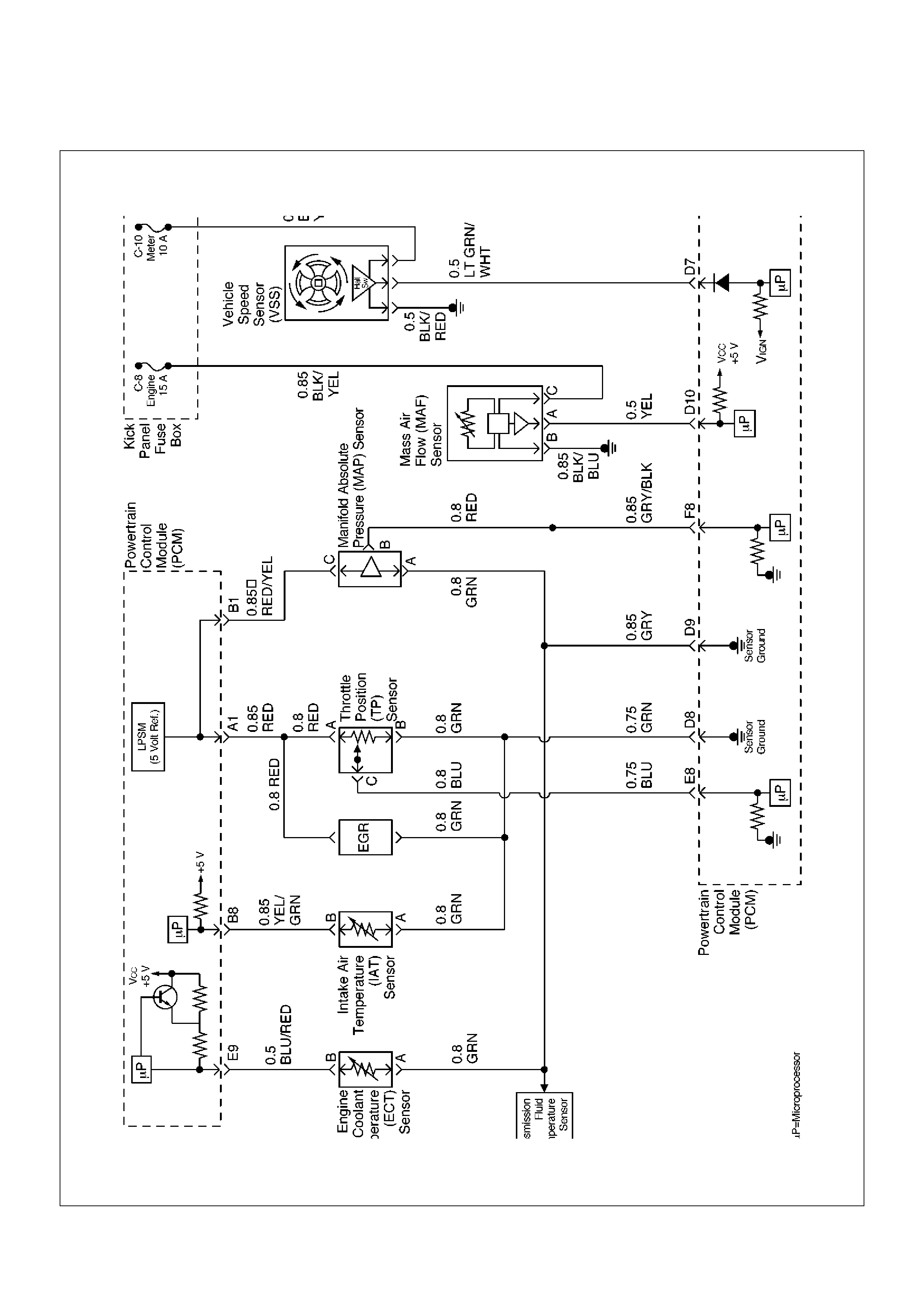
PCM Wiring Diagram (4 of 7)
D06RW138
PCM Wiring Diagram (5 of 7)
D06RW137
PCM Wiring Diagram (6 of 7)
D06RW099
PCM Wiring Diagram (7 of 7)
D06RW136
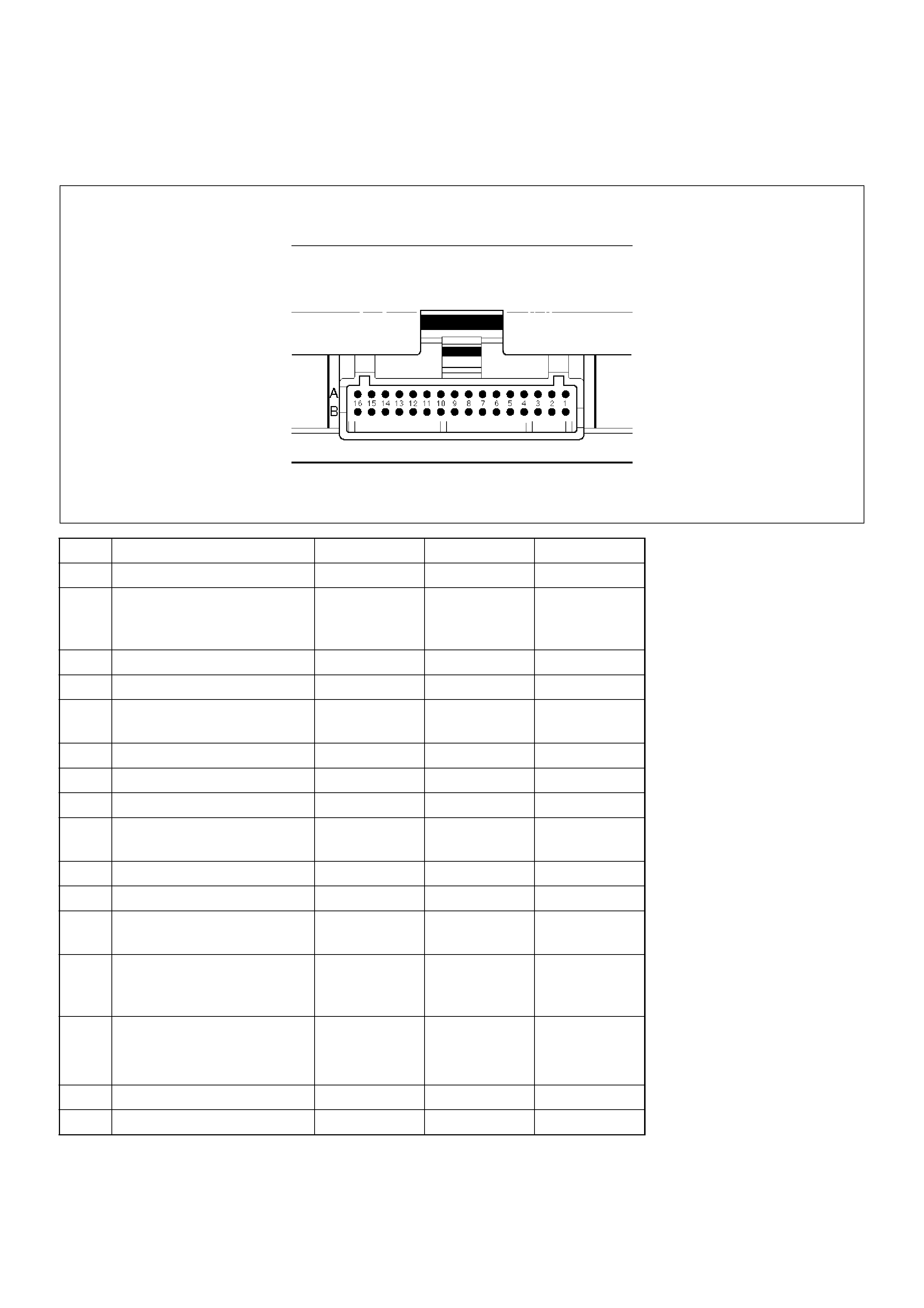
PCM Pinouts
PCM Pinout Table, 32-Way Red Connector – Row “A”
TS23344
PIN PIN Function Wire Color IGN ON ENG RUN
A1 5 Volt Reference “A” RED 5.0 V 5.0 V
A2 Knock Sensor YEL 0.0 V DC
2mV AC
0.0 V DC
18mV AC (at
idle)
A3 Not Used — — —
A4 Battery Feed WHT B+ B+
A5 Idle Air Control (IAC)
“A”High
BLU B+/0.8 V B+/0.8 V
A6 IAC “A” Low BLU/WHT B+/0.8 V B+/0.8 V
A7 IAC “B” Low BLU/BLK B+/0.8 V B+/0.8 V
A8 IAC “B” High BLU/RED B+/0.8 V B+/0.8 V
A9 Automatic Transmission
Fluid (ATF) Lamp
ORN/BLU B+ B+
A10 Winter Lamp PNK/GRN B+ B+
A11 Power Lamp GRY/WHT B+ B+
A12 Antilock Brake System
(ABS)
GRY B+ B+
A13 Malfunction Indicator
(Check Engine or MIL)
Lamp/Immobiliser
BLU 0.0 V B+
A14 “Check Transmission”
Lamp Driver (AT)
ORN/BLK B+ B+
A15 EVAP RED/BLU B+ 5.0 V
A16 Band Apply (AT) BRN/YEL B+ B+
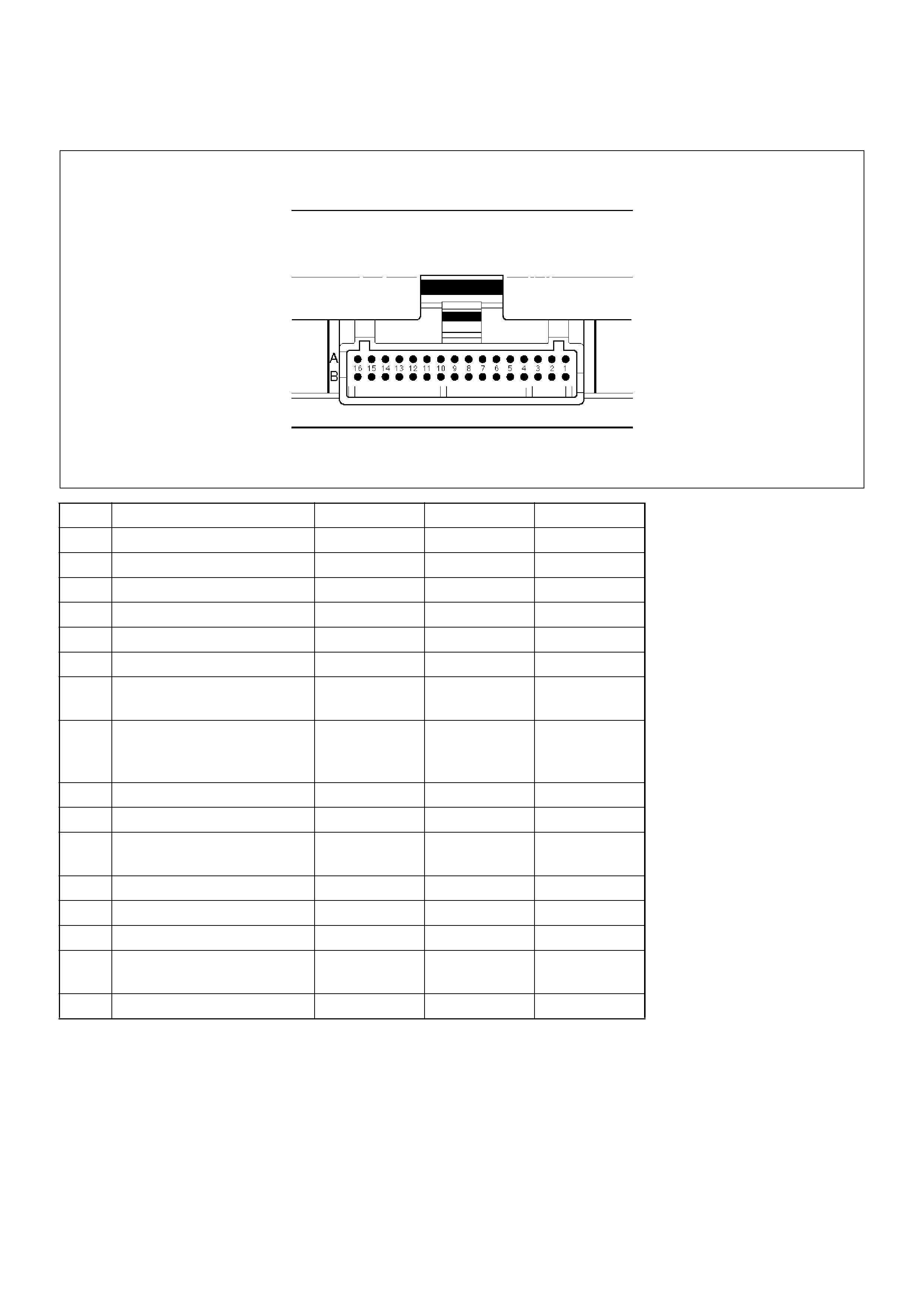
PCM Pinout Table, 32-Way Red Connector – Row “B”
TS23344
PIN PIN Function Wire Color IGN ON ENG RUN
B1 5 Volt Reference “B” RED/YEL 5.0 V 5.0 V
B2 lgnition coil RED/WHT 0.0 V 0.1 V
B3 lgnition coil RED/BLK 0.0 V 0.1 V
B4 lgnition coil RED/GRN 0.0 V 0.1 V
B5 Not Used — — —
B6 Not Used — — —
B7 Exhaust Gas Recirculation
(EGR)
YEL/RED 0.6 V 0.6 V
B8 Intake Air Temperature
(IAT) Sensor
YEL/GRN 0.5-4.9 V
(depends on
temperature)
0.5-4.9 V
(depends on
temperature)
B9 Not Used — — —
B10 Not Used — — —
B11 Power Steering Pressure
(PSP) Switch
GRN/YEL B+ B+
B12 Illuminated Switch GRN B+ B+
B13 Class 2 Data ORN/GRN 0.0 V 0.0 V
B14 A/C Clutch GRN/BLK B+ (A/C OFF) B+ (A/C OFF)
B15 ECM to ECU
Communication
Violet 0.0 V 0.1 V
B16 Not Used — — —
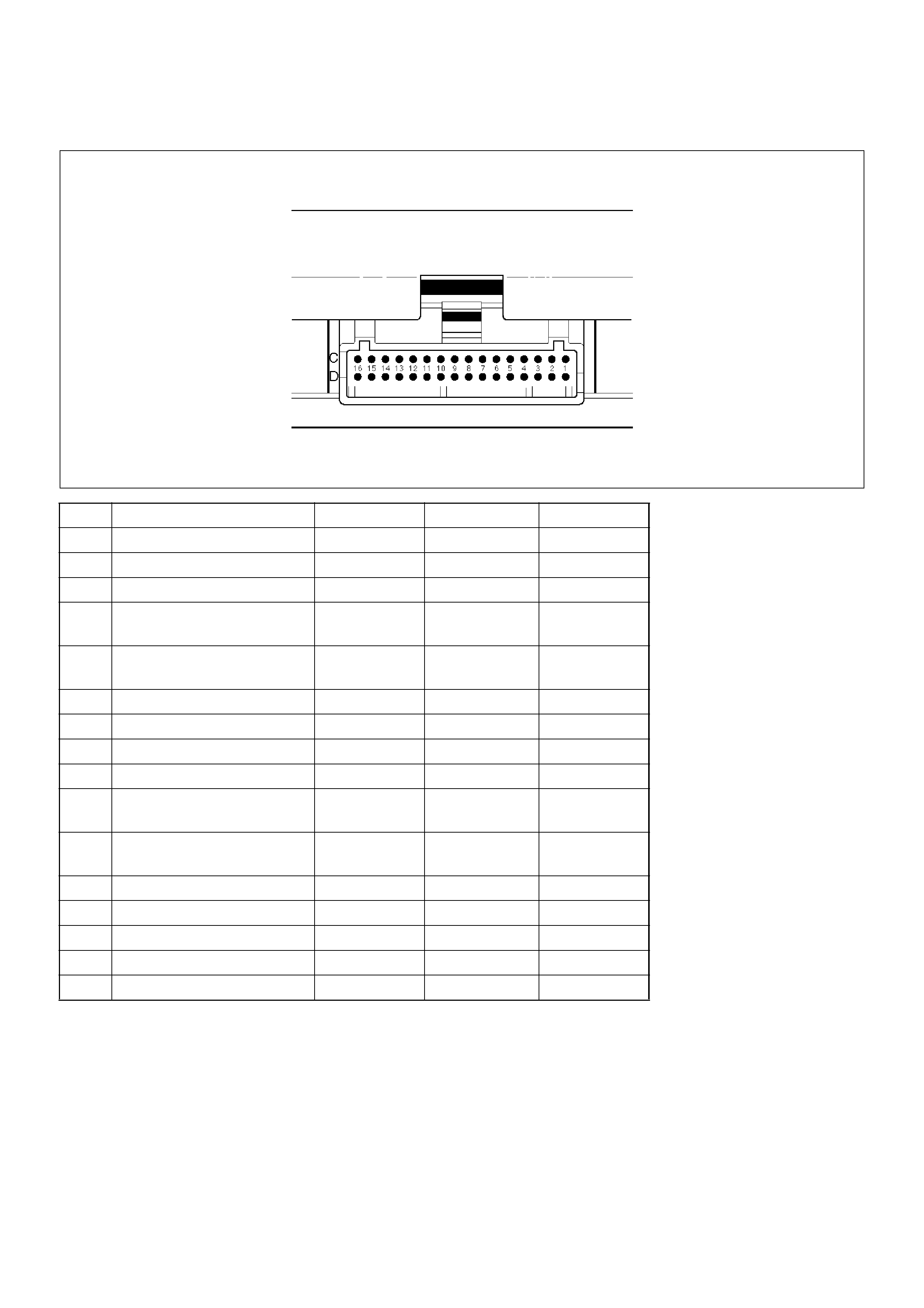
PCM Pinout Table, 32-Way White Connector – Row “C”
TS23345
PIN PIN Function Wire Color IGN ON ENG RUN
C1 Injector Cylinder #4 GRN/RED B+ B+
C2 Shift “B” Solenoid BRN/BLK 0.0 V 0.0 V
C3 Injector Cylinder #6 GRN/YEL B+ B+
C4 Ignition Control (IC)
Cylinder #1
RED 0.0 V 0.1 V
C5 Crankshaft Position
Sensor, “A”Circuit
YEL 0.3 V to 5 V 2.2 V
C6 Not Used — — —
C7 PCM Ground BLK/BLU 0.0 V 0.0 V
C8 PCM Ground BLK/PNK 0.0 V 0.0 V
C9 PCM Ground BLK/BLU 0.0 V 0.0 V
C10 Tachometer BLK/RED 8.8 V 10.0 V (at
idle)
C11 Variable Intake Manifold YEL/BLK 0.0 V B+ (rpm 3600
over)
C12 Not Used — — —
C13 Not Used — — —
C14 Not Used — — —
C15 Not Used — — —
C16 Not Used — — —
PCM Pinout Table, 32-Way White Connector – Row “D”
TS23345
PIN PIN Function Wire Color IGN ON ENG RUN
D1 Injector Cylinder #2 GRN/ORN B+ B+
D2 Torque Converter Clutch
(TCC)
BRN/BLU 0.0 V 0.0 V
D3 Injector Cylinder #1 GRN/WHT B+ B+
D4 Serial Data (8192) ORN 5.0 V 5.0 V
D5 Ignition Control, Cylinder
#5
RED/YEL 0.0 V 0.1 V
D6 Ignition Control, Cylinder
#3
RED/BLUE 0.0 V 0.0 V
D7 VSS Input / IMOB
Response
WHT/BLK 0.0 V 0.1 V (at rest)
D8 Sensor Ground 5V
Reference A Return
GRN 0.0 V 0.0 V
D9 Sensor Ground 5 V
Reference B Return
GRY 0.0 V 0.0 V
D10 Mass Air Flow (MAF) YEL 4.9 V 4.2 V
D11 Camshaft Position Sensor WHT 5.0 V or less
than 1.0 V
4.6 V
D12 Not Used — — —
D13 Not Used — — —
D14 Bank 1 HO2S 1 Low GRN 0.0 V 0.1 V
D15 Bank 1 HO2S 1 Signal RED 0.4 V 0.1-0.9 V
D16 Not Used — — —
PCM Pinout Table, 32-Way Blue Connector – Row “E”
TS23346
PIN PIN Function Wire Color IGN ON ENG RUN
E1 Transmission Output Shaft
Sensor (TOSS) High
RED 0.0 V 0.1 V
E2 Transmission Output Shaft
Sensor (TOSS) Low
WHT 0.0 V 0.0 V
E3 Pressure Control Solenoid
Low
PPL/RED 0.0 V 1.1 V
E4 Pressure Control Solenoid
High
PPL/WHT 0.0 V 4.9 V
E5 Exhaust Gas Recirculation
(EGR) Control High
BLK/YEL B+ B+
E6 Exhaust Gas Recirculation
(EGR) Control Low
YEL B+ B+
E7 Transmission Range Signal
“B”
BLU/YEL 0.0 V 0.0 V
E8 Throttle Position (TP)
Sensor
BLU 0.5-0.8 V 0.5-0.8 V (at
idle)
E9 Engine Coolant
Temperature (ECT) Sensor
BLU/RED 0.5-4.9 V
(depends on
temperature)
0.5-4.9 V
(depends on
temperature)
E10 Not Used — — —
E11 Crankshaft Position (CKP)
Sensor +5 Volt Reference
YEL/RED 5.0 V or less
than 1.0 V
5.0 V
E12 Transmission Range Signal
“A”
BLU/WHT B+ B+
E13 Fuel Pump (FP) Relay RED/WHT 0.0 V B+
E14 Shift High (BAND APPLY) BRN/WHT B+ B+
E15 A/C Request GRN/ORN 0.0 V 0.0 V
E16 Ignition Feed (1 of 2 F16) RED/BLU B+ B+
PCM Pinout Table, 32-Way Blue Connector – Row “F”
TS23346
PIN PIN Function Wire Color IGN ON ENG RUN
F1 Not Used — — —
F2 Transmission Range Signal
“C”
BLU/BLK 0.0 V 0.0 V
F3 Transmission Range Signal
“P”
YEL/GRN B+ 0.0 V
F4 Brake Switch GRN/YEL 0.0 V 0.0 V
F5 Power Switch PPL/RED B+ B+
F6 Winter Switch PPL/GRN B+ B+
F7 Transmission Fluid
Temperature
RED/BLK 0.5-4.9 V
(depends on
temperature)
0.5-4.9 V
(depends on
temperature)
F8 Manifold Absolute Pressure
(MAP)
GRY/BLK 3.5-4.9 V
(depends on
altitude and
barometric
pressure)
0.6-1.3 V
F9 Not Used — — —
F10 Cruise Control GRY/BLU B+ B+
F11 Kickdown Switch LT BLU B+ B+
F12 DIAG ORN/BLU B+ B+
F13 Injector “C” Cylinder #3 GRN B+ B+
F14 Shift “A” Solenoid BRN/RED B+ B+
F15 Injector Cylinder #5 GRN/BLK B+ B+
F16 Ignition Feed (1 of 2 E16) RED/BLU B+ B+
Component Locators
Engine Component Locator
060RW210

Engine Component Locator Table
Number Name Location
1 Linear Exhaust Gas Recirculation (EGR) Valve Rear right side of the engine
2 Throttle Position (TP) Sensor On the rear of the throttle body
3 Intake Air Temperature (IAT) Sensor On the intake air duct near the throttle body
4 Check Engine (MIL) Light On the instrument panel beneath the tachometer
5 Positive Crankcase Ventilation (PCV) Valve On the left of the cylinder head cover
6 Air Cleaner Left front of the engine bay
7 Mass Air Flow (MAF) Sensor Attached to the air filter box
8 Camshaft Position (CMP) Sensor On the rear right side at the left of the cylinder
head cover
9 Fuel Pressure Regulator Rear right side of the engine
10 Idle Air Control (IAC) Valve On the left of the throttle body
11 Upper Intake Manifold Top of the engine
12 Fuse/Relay Box Along the inside of the right fender
13 Manifold Absolute Pressure (MAP) Sensor Bolted to the top of the upper intake manifold
14 Throttle Body Between the intake air duct and the upper intake
manifold
15 Engine Coolant Temperature Sensor On the coolant crossover pipe at the front of the
engine, near the throttle body
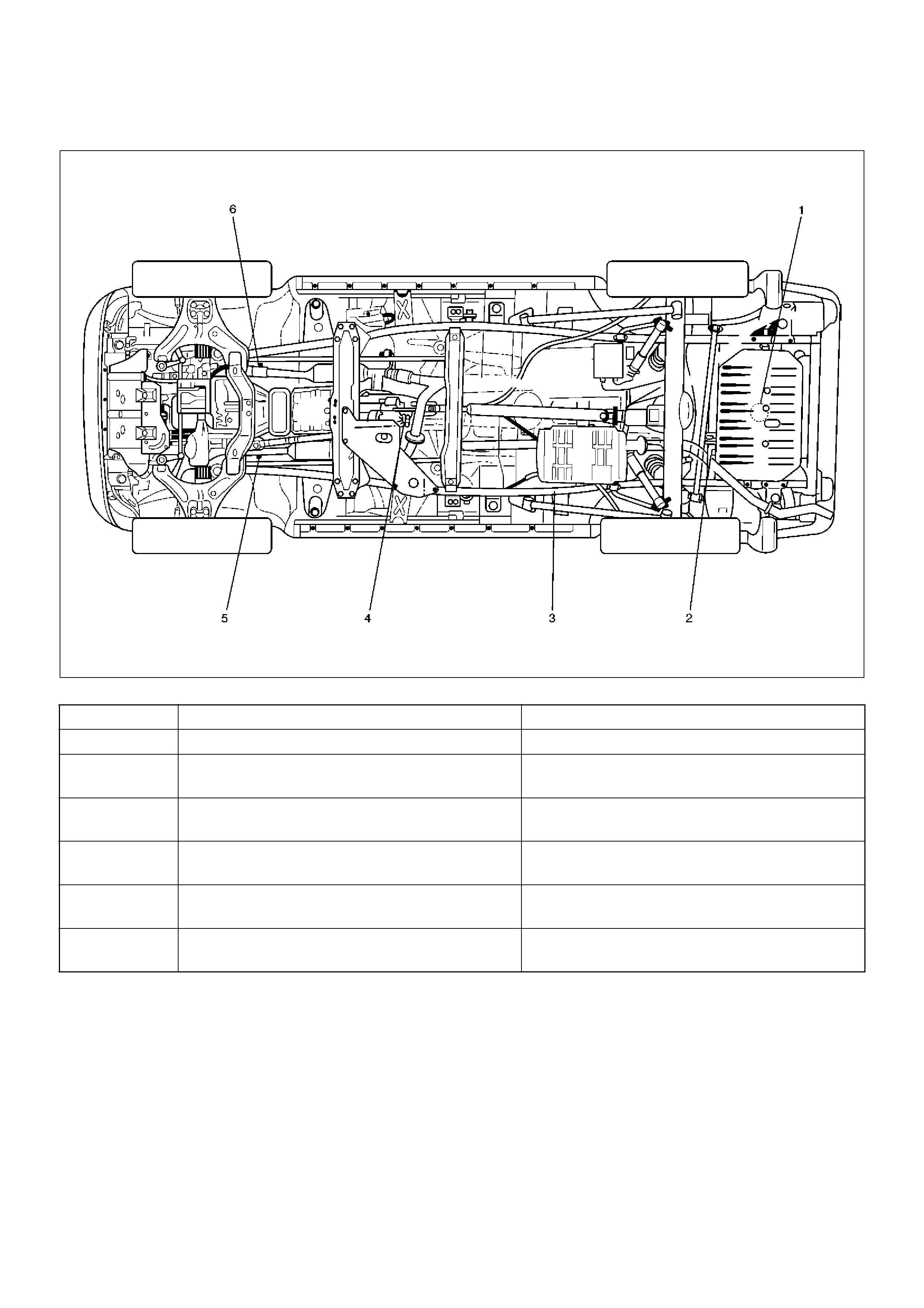
Undercarriage Component Locator
F00RW040
Undercarriage Component Locator Table (Automatic Transmission)
Number Name Location
1 Fuel Pump Assembly Installed in the top of the fuel tank
2 Fuel Gauge Unit Installed in the front edge of the fuel tank, on the
right side
3 Fuel Filter Located along the inside of the right frame rail,
ahead of the rear axle
4 Vehicle Speed Sensor (VSS) Protrudes from the rear output shaft housing of
the transfer case.
5 Heated Oxygen Sensor (Bank 1, HO2S 1) Threaded into the exhaust pipe ahead of the
right-hand catalytic converter
6 Heated Oxygen Sensor (Bank 2, HO2S 1) Threaded into the exhaust pipe ahead the
left-hand catalytic converter
Undercarriage Component Locator Table (Manual Transmission)
Fuse and Relay Panel (Underhood Electrical Center)
TS23336
Number Name Location
1 Fuel Pump Assembly Installed in the top of the fuel tank
2 Fuel Gauge Unit Installed in the front edge of the right frame rail,
ahead of the rear axle
3 Fuel Filter Located along the inside of the right frame rail,
ahead of the rear axle
4 Vehicle Speed Sensor (VSS) Protrudes from the rear output shaft housing of
the transfer case.
5 Heated Oxygen Sensor (Bank 1, HO2S 1) Threaded into the exhaust pipe ahead of the
right-hand catalytic converter
6 Heated Oxygen Sensor (Bank 2, HO2S 1) Threaded into the exhaust pipe ahead of the
left-hand catalytic converter
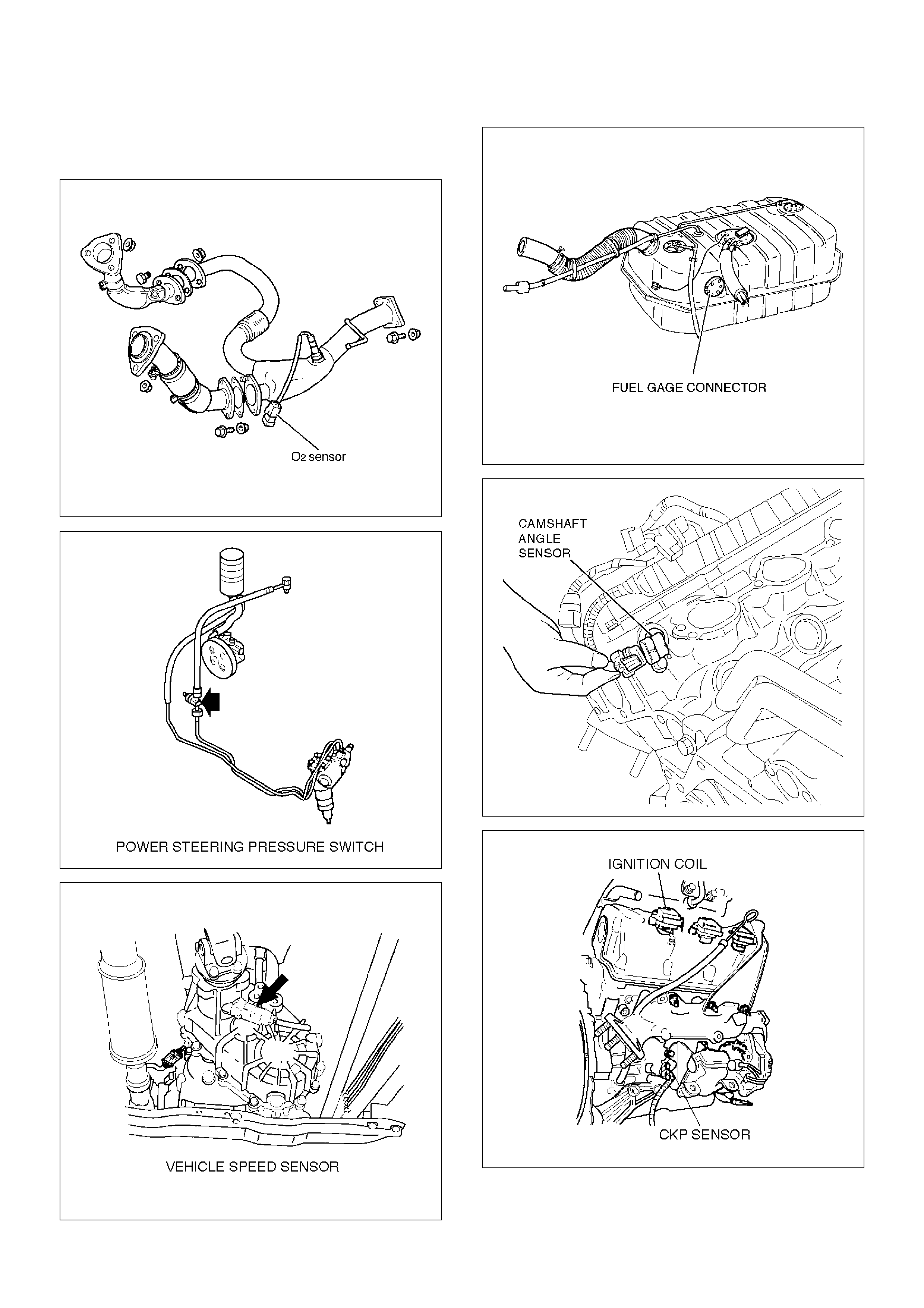
Sensors and Miscellaneous Component
Locator
150RW101
T321066
T321067
140RW032
014RW125
T321070
055RW003
041RW004
025RW005
T321078
060RW007
028RW001

Diagnosis
Strategy-Based Diagnostics
Strategy-Based Diagnostics
The strategy-based diagnostic is a uniform approach to
repair all Electrical/Electronic (E/E) systems. The
diagnostic flow can always be used to resolve an E/E
system problem and is a starting point when repairs are
necessary. The following steps will instruct the
technician how to proceed with a diagnosis:
1.Verify the customer complaint.
•To verify the customer complaint, the technician
should know the normal operation of the system.
2.Perform preliminary checks.
•Conduct a thorough visual inspection.
•Review the service history.
•Detect unusual sounds or odors.
•Gather diagnostic trouble code information to
achieve an effective repair.
3.Check bulletins and other service information.
•This includes videos, newsletters, etc.
4.Refer to service information (manual) system
check(s).
•“System checks” contain information on a system
that may not be supported by one or more DTCs.
System checks verify proper operation of the
system. This will lead the technician in an
organized approach to diagnostics.
5.Refer to service diagnostics.
DTC Stored
Follow the designated DTC chart exactly to make an
effective repair.
No DTC
Select the symptom from the symptom tables. Follow
the diagnostic paths or suggestions to complete the
repair. You may refer to the applicable component/
system check in the system checks.
No Matching Symptom
1.Analyze the complaint.
2.Develop a plan for diagnostics.
3.Utilize the wiring diagrams and the theory of
operation.
Call technical assistance for similar cases where repair
history may be available. Combine technician
knowledge with efficient use of the available service
information.
Intermittents
Conditions that are not always present are called
intermittents. To resolve intermittents, perform the
following steps:
1.Observe history DTCs, DTC modes, and
freezeframe data.
2.Evaluate the symptoms and the conditions
described by the customer.
3.Use a check sheet or other method to identify the
circuit or electrical system component.
4.Follow the suggestions for intermittent diagnosis
found in the service documentation.
Most Tech 2s, such as the Tech II and the 5–8840–
0285–0 (Fluke model 87 DVOM), have data-capturing
capabilities that can assist in detecting intermittents.
No Trouble Found
This condition exists when the vehicle is found to
operate normally. The condition described by the
customer may be normal. Verify the customer
complaint against another vehicle that is operating
normally. The condition may be intermittent. Verify the
complaint under the conditions described by the
customer before releasing the vehicle.
1.Re-examine the complaint.
When the Complaint cannot be successfully found
or isolated, a re-evaluation is necessary. The
complaint should be re-verified and could be
intermittent as defined in Intermittents, or could be
normal.
2.Repair and verify.
After isolating the cause, the repairs should be
made. Validate for proper operation and verify that
the symptom has been corrected. This may involve
road testing or other methods to verify that the
complaint has been resolved under the following
conditions:
•Conditions noted by the customer.
•If a DTC was diagnosed, verify a repair by
duplicating conditions present when the DTC was
set as noted in the Failure Records or Freeze
Frame data.
Verifying Vehicle Repair
Verification of the vehicle repair will be more
comprehensive for vehicles with OBD system
diagnostics. Following a repair, the technician should
perform the following steps:
Important: Follow the steps below when you verify
repairs on OBD systems. Failure to follow these steps
could result in unnecessary repairs.
1. Review and record the Failure Records and the
Freeze Frame data for the DTC which has been
diagnosed (Freeze Frame data will only be stored
for an A or B type diagnostic and only if the
MIL("Check Engine" lamp) has been requested).
2. Clear the DTC(S).

3. Operate the vehicle within conditions noted in the
Failure Records and Freeze Frame data.
4. Monitor the DTC status information for the specific
DTC which has been diagnosed until the diagnostic
test associated with that DTC runs.
General Service Information
OBD Serviceablity Issues
The list of non-vehicle faults that could affect the
performance of the OBD system has been compiled.
These non-vehicle faults vary from environmental
conditions to the quality of fuel used.
The illumination of the MIL (“Check Engine”lamp) due to
a non-vehicle fault could lead to misdiagnosis of the
vehicle, increased warranty expense and customer
dissatisfaction. The following list of non-vehicle faults
does not include every possible fault and may not apply
equally to all product lines.
Fuel Quality
Using fuel with the wrong octane rating for your vehicle
may cause driveability problems. Many of the major
fuel companies advertise that using “premium” gasoline
will improve the performance of your vehicle. Most
premium fuels use alcohol to increase the octane rating
of the fuel. Although alcohol-enhanced fuels may raise
the octane rating, the fuel's ability to turn into vapor in
cold temperatures deteriorates. This may affect the
starting ability and cold driveability of the engine.
Low fuel levels can lead to fuel starvation, lean engine
operation, and eventually engine misfire.
Non-OEM Parts
All of the OBD diagnostics have been calibrated to run
with OEM parts. Something as simple as a
high-performance exhaust system that affects exhaust
system back pressure could potentially interfere with the
operation of the EGR valve and thereby turn on the MIL
(“Check Engine”lamp). Small leaks in the exhaust
system near the post catalyst oxygen sensor can also
cause the MIL (“Check Engine”lamp) to turn on.
Aftermarket electronics, such as cellular phones,
stereos, and anti-theft devices, may radiate EMI into the
control system if they are improperly installed. This may
cause a false sensor reading and turn on the MIL
(“Check Engine”lamp).
Environment
Temporary environmental conditions, such as localized
flooding, will have an effect on the vehicle ignition
system. If the ignition system is rain-soaked, it can
temporarily cause engine misfire and turn on the MIL
(“Check Engine”lamp).
Poor Vehicle Maintenance
The sensitivity of OBD diagnostics will cause the MIL
(“Check Engine”lamp) to turn on if the vehicle is not
maintained properly. Restricted air filters, fuel filters,
and crankcase deposits due to lack of oil changes or
improper oil viscosity can trigger actual vehicle faults
that were not previously monitored prior to OBD. Poor
vehicle maintenance can not be classified as
a“non-vehicle fault”, but with the sensitivity of OBD
diagnostics, vehicle maintenance schedules must be
more closely followed.
Related System Faults
Many of the OBD system diagnostics will not run if the
PCM detects a fault on a related system or component.
One example would be that if the PCM detected a
Misfire fault, the diagnostics on the catalytic converter
would be suspended until Misfire fault was repaired. If
the Misfire fault was severe enough, the catalytic
converter could be damaged due to overheating and
would never set a Catalyst DTC until the Misfire fault
was repaired and the Catalyst diagnostic was allowed to
run to completion. If this happens, the customer may
have to make two trips to the dealership in order to
repair the vehicle.
Maintenance Schedule
Refer to the Maintenance Schedule.
Visual / Physical Engine Compartment
Inspection
Perform a careful visual and physical engine
compartment inspection when performing any
diagnostic procedure or diagnosing the cause of an
emission test failure. This can often lead to repairing a
problem without further steps. Use the following
guidelines when performing a visual/physical
inspection:
• Inspect all vacuum hoses for punches, cuts,
disconnects, and correct routing.
• Inspect hoses that are difficult to see behind other
components.
• Inspect all wires in the engine compartment for
proper connections, burned or chafed spots, pinched
wires, contact with sharp edges or contact with hot
exhaust manifolds or pipes.
Basic Knowledge of Tools Required
NOTE: Lack of basic knowledge of this powertrain
when performing diagnostic procedures could result in
an incorrect diagnosis or damage to powertrain
components. Do not attempt to diagnose a powertrain
problem without this basic knowledge.
A basic understanding of hand tools is necessary to
effectively use this section of the Service Manual.

Serial Data Communications
Class II Serial Data Communications
This vehicle utilizes the “Class II” communication
system. Each bit of information can have one of two
lengths: long or short. This allows vehicle wiring to be
reduced by transmitting and receiving multiple signals
over a single wire. The messages carried on Class II
data streams are also prioritized. If two messages
attempt to establish communications on the data line at
the same time, only the message with higher priority will
continue. The device with the lower priority message
must wait. The most significant result of this regulation
is that it provides Tech 2 manufacturers with the
capability to access data from any make or model
vehicle that is sold.
The data displayed on the other Tech 2 will appear the
same, with some exceptions. Some Tech 2s will only be
able to display certain vehicle parameters as values that
are a coded representation of the true or actual value.
For more information on this system of coding, refer to
Decimal/Binary/Hexadecimal Conversions. On this
vehicle Tech 2 displays the actual values for vehicle
parameters. It will not be necessary to perform any
conversions from coded values to actual values.
On-Board Diagnostic (OBD)
On-Board Diagnostic Tests
A diagnostic test is a series of steps, the result of which
is a pass or fail reported to the diagnostic executive.
When a diagnostic test reports a pass result, the
diagnostic executive records the following data:
• The diagnostic test has been completed since the
last ignition cycle.
• The diagnostic test has passed during the current
ignition cycle.
• The fault identified by the diagnostic test is not
currently active.
When a diagnostic test reports a fail result, the
diagnostic executive records the following data:
• The diagnostic test has been completed since the
last ignition cycle.
• The fault identified by the diagnostic test is currently
active.
• The fault has been active during this ignition cycle.
• The operating conditions at the time of the failure.
Remember, a fuel trim DTC may be triggered by a list of
vehicle faults. Make use of all information available
(other DTCs stored, rich or lean condition, etc.) when
diagnosing a fuel trim fault.
Comprehensive Component Monitor
Diagnostic Operation
Input Components:
Input components are monitored for circuit continuity
and out-of-range values. This includes rationality
checking. Rationality checking refers to indicating a
fault when the signal from a sensor does not seem
reasonable, i.e. Throttle Position (TP) sensor that
indicates high throttle position at low engine loads or
MAP voltage. Input components may include, but are
not limited to the following sensors:
• Vehicle Speed Sensor (VSS)
• Crankshaft Position (CKP) sensor
• Knock Sensor (KS)
• Throttle Position (TP) sensor
• Engine Coolant Temperature (ECT) sensor
• Camshaft Position (CMP) sensor
• Manifold Absolute Pressure (MAP) sensor
• Mass Air Flow (MAF) sensor
In addition to the circuit continuity and rationality check,
the ECT sensor is monitored for its ability to achieve a
steady state temperature to enable closed loop fuel
control.
Output Components:
Output components are diagnosed for proper response
to control module commands. Components where
functional monitoring is not feasible will be monitored for
circuit continuity and out-of-range values if applicable.
Output components to be monitored include, but are not
limited to, the following circuits:
• Idle Air Control (IAC) Motor
• Electronic Transmission controls
•A/C relays
• Cooling fan relay
• VSS output
• MIL control
• Cruise control inhibit
Refer to PCM and Sensors in General Descriptions.
Passive and Active Diagnostic Tests
A passive test is a diagnostic test which simply monitors
a vehicle system or component. Conversely, an active
test, actually takes some sort of action when performing
diagnostic functions, often in response to a failed
passive test. For example, the EGR diagnostic active
test will force the EGR valve open during closed throttle
decel and/or force the EGR valve closed during a
steady state. Either action should result in a change in
manifold pressure.
Intrusive Diagnostic Tests
This is any on-board test run by the Diagnostic
Management System which may have an effect on
vehicle performance or emission levels.
Warm-Up Cycle
A warm-up cycle means that engine at temperature
must reach a minimum of 70°C (160°F) and rise at least
22°C (40°F) over the course of a trip.

Freeze Frame
Freeze Frame is an element of the Diagnostic
Management System which stores various vehicle
information at the moment an emissions-related fault is
stored in memory and when the MIL is commanded on.
These data can help to identify the cause of a fault.
Refer to Storing And Erasing Freeze Fame Data for
more detailed information.
Failure Records
Failure Records data is an enhancement of the OBD
Freeze Frame feature. Failure Records store the same
vehicle information as does Freeze Frame, but it will
store that information for any fault which is stored in
on-board memory, while Freeze Frame stores
information only for emission-related faults that
command the MIL on.
Common OBD Terms
Diagnostic
When used as a noun, the word diagnostic refers to any
on-board test run by the vehicle's Diagnostic
Management System. A diagnostic is simply a test run
on a system or component to determine if the system or
component is operating according to specification.
There are many diagnostics, shown in the following list:
• Oxygen sensors
• Oxygen sensor heaters
•EGR
• Catalyst monitoring
Enable Criteria
The term “enable criteria” is engineering language for
the conditions necessary for a given diagnostic test to
run. Each diagnostic has a specific list of conditions
which must be met before the diagnostic will run.
“Enable criteria”is another way of saying“conditions
required”.
The enable criteria for each diagnostic is listed on the
first page of the DTC description under the
heading“Conditions for Setting the DTC”. Enable criteria
varies with each diagnostic, and typically includes, but
is not limited to the following items:
• engine speed
• vehicle speed
•ECT
•MAF/MAP
• barometric pressure
•IAT
•TP
• fuel trim
• TCC enabled
•A/C on
Trip
Technically, a trip is a key on-run-key off cycle in which
all the enable criteria for a given diagnostic are met,
allowing the diagnostic to run. Unfortunately, this
concept is not quite that simple. A trip is official when all
the enable criteria for a given diagnostic are met. But
because the enable criteria vary from one diagnostic to
another, the definition of trip varies as well. Some
diagnostic are run when the vehicle is at operating
temperature, some when the vehicle first start up; some
require that the vehicle be cruising at a steady highway
speed, some run only when the vehicle is idle; some
diagnostics function with the TCC disables. Some run
only immediately following a cold engine start-up.
A trip then, is defined as a key on-run-key off cycle in
which the vehicle was operated in such a way as to
satisfy the enables criteria for a given diagnostic, and
this diagnostic will consider this cycle to be one trip.
However, another diagnostic with a different set of
enable criteria (which were not met) during this driving
event, would not consider it a trip. No trip will occur for
that particular diagnostic until the vehicle is driven in
such a way as to meet all the enable criteria.
The Diagnostic Executive
The Diagnostic Executive is a unique segment of
software which is designed to coordinate and prioritize
the diagnostic procedures as well as define the protocol
for recording and displaying their results. The main
responsibilities of the Diagnostic Executive are listed as
following:
• Commanding the MIL (“Check Engine”lamp) on and
off
• DTC logging and clearing
• Freeze Frame data for the first emission related DTC
recorded
• Non-emission related Service Lamp (future)
• Operating conditions Failure Records buffer, (the
number of records will vary)
• Current status information on each diagnostic
The Diagnostic Executive records DTCs and turns on
the MIL when emission-related faults occur. It can also
turn off the MIL if the conditions cease which caused
the DTC to set.
Diagnostic Information
The diagnostic charts and functional checks are
designed to locate a faulty circuit or component through
a process of logical decisions. The charts are prepared
with the requirement that the vehicle functioned
correctly at the time of assembly and that there are not
multiple faults present.
There is a continuous self-diagnosis on certain control
functions. This diagnostic capability is complemented
by the diagnostic procedures contained in this manual.
The language of communicating the source of the
malfunction is a system of diagnostic trouble codes.

When a malfunction is detected by the control module, a
diagnostic trouble code is set and the Malfunction
Indicator Lamp (MIL) (“Check Engine”lamp) is
illuminated.
Malfunction Indicator Lamp (MIL)
The Malfunction Indicator Lamp (MIL) looks the same
as the MIL you are already familiar with (“Check
Engine”lamp). However, OBD requires that the it
illuminate under a strict set of guide lines.
Basically, the MIL is turned on when the PCM detects a
DTC that will impact the vehicle emissions.
The MIL is under the control of the Diagnostic
Executive. The MIL will be turned on if an
emissions-related diagnostic test indicates a
malfunction has occurred. It will stay on until the system
or component passes the same test, for three
consecutive trips, with no emissionsrelated faults.
Extinguishing the MIL
When the MIL is on, the Diagnostic Executive will turn
off the MIL after three consecutive trips that a “test
passed” has been reported for the diagnostic test that
originally caused the MIL to illuminate.
Although the MIL has been turned off, the DTC will
remain in the PCM memory (both Freeze Frame and
Failure Records) until forty(40) warm-up cycles after no
faults have been completed.
If the MIL was set by either a fuel trim or misfire-related
DTC, additional requirements must be met. In addition
to the requirements stated in the previous paragraph,
these requirements are as follows:
• The diagnostic tests that are passed must occur with
375 RPM of the RPM data stored at the time the last
test failed.
• Plus or minus ten (10) percent of the engine load that
was stored at the time the last failed.
• Similar engine temperature conditions (warmed up or
warming up ) as those stored at the time the last test
failed.
Meeting these requirements ensures that the fault which
turned on the MIL has been corrected.
The MIL (“Check Engine”lamp) is on the instrument
panel and has the following function:
• It informs the driver that a fault affects vehicle
emission levels has occurred and that the vehicle
should be taken for service as soon as possible.
• As a bulb and system check, the MIL will come “ON”
with the key “ON” and the engine not running. When
the engine is started, the MIL will turn “OFF.”
• When the MIL remains “ON” while the engine is
running, or when a malfunction is suspected due to a
driveability or emissions problem, a Powertrain
On-Board Diagnostic (OBD ll) System Check must be
performed. The procedures for these checks are
given in On-Board Diagnostic (OBD) System Check.
These checks will expose faults which may not be
detected if other diagnostics are performed first.
DTC Types
Each DTC is directly related to a diagnostic test. The
Diagnostic Management System sets DTC based on
the failure of the tests during a trip or trips. Certain
tests must fail two (2) consecutive trips before the DTC
is set. The following are the four (4) types of DTCs and
the characteristics of those codes:
•Type A
• Emissions related
• Requests illumination of the MIL of the first trip with
a fail
• Stores a History DTC on the first trip with a fail
• Stores a Freeze Frame (if empty)
• Stores a Fail Record
• Updates the Fail Record each time the diagnostic
test fails
•Type B
• Emissions related
• “Armed” after one (1) trip with a fail
• “Disarmed” after one (1) trip with a pass
• Requests illumination of the MIL on the second
consecutive trip with a fail
• Stores a History DTC on the second consecutive
trip with a fail (The DTC will be armed after the first
fail)
• Stores a Freeze Frame on the second consecutive
trip with a fail (if empty)
• Stores a Fail Record when the first test fails (not
dependent on consecutive trip fails)
• Updates the Fail Record each time the diagnostic
test fails
• Type C (if the vehicle is so equipped)
• Non-Emissions related
• Requests illumination of the Service Lamp or the
service message on the Drive Information Center
(DIC) on the first trip with a fail
• Stores a History DTC on the first trip with a fail
•Does not store a Freeze Frame
• Stores Fail Record when test fails
• Updates the Fail Record each time the diagnostic
test fails
•Type D (Type D non-emissions related are not
utilized on certain vehicle applications).
• Non-Emissions related
• Dose not request illumination of any lamp
• Stores a History DTC on the first trip with a fail
•Does not store a Freeze Frame
• Stores Fail Record when test fails
• Updates the Fail Record each time the diagnostic
test fails

Important: Only four Fail Records can be stored. Each
Fail Record is for a different DTC. It is possible that
there will not be Fail Records for every DTC if multiple
DTCs are set.
Storing and Erasing Freeze Frame Data and Failure
Records
The data captured is called Freeze Frame data. The
Freeze Frame data is very similar to a single record of
operating conditions. Whenever the MIL is illuminated,
the corresponding record of operating conditions is
recorded to the Freeze Frame buffer.
Data from these faults take precedence over data
associated with any other fault. The Freeze Frame data
will not be erased unless the associated history DTC is
cleared.
Each time a diagnostic test reports a failure, the current
engine operating conditions are recorded in the Failure
Records buffer. A subsequent failure will update the
recorded operating conditions. The following operating
conditions for the diagnostic test which failed typically
include the following parameters:
•Air Fuel Ratio
•Air Flow Rate
•Fuel Trim
•Engine Speed
•Engine Load
•Engine Coolant Temperature
•Vehicle Speed
•TP Angle
•MAP/BARO
•Injector Base Pulse Width
•Loop Status
Intermittent Malfunction Indicator Lamp
In the case of an “intermittent” fault, the MIL (“Check
Engine”lamp) may illuminate and then (after three trips)
go“OFF”. However, the corresponding diagnostic
trouble code will be stored in the memory. When
unexpected diagnostic trouble codes appear, check for
an intermittent malfunction.
A diagnostic trouble code may reset. Consult the
“Diagnostic Aids” associated with the diagnostic trouble
code. A physical inspection of the applicable
sub-system most often will resolve the problem.
Data Link Connector (DLC)
The provision for communication with the control
module is the Data Link Connector (DLC). The DLC is
used to connect to Tech 2. Some common uses of Tech
2 are listed below:
•Identifying stored Diagnostic Trouble Codes (DTCs).
•Clearing DTCs.
•Performing output control tests.
•Reading serial data.
TS24064
Verifying Vehicle Repair
Verification of vehicle repair will be more
comprehensive for vehicles with OBD system
diagnostic. Following a repair, the technician should
perform the following steps:
1.Review and record the Fail Records and/or Freeze
Frame data for the DTC which has been diagnosed
(Freeze Frame data will only be stored for an A or B
type diagnostic and only if the MIL has been
requested).
2.Clear DTC(s).
3.Operate the vehicle within conditions noted in the
Fail Records and/or Freeze Frame data.
4.Monitor the DTC status information for the specific
DTC which has been diagnosed until the diagnostic
test associated with that DTC runs.
Following these steps are very important in verifying
repairs on OBD systems. Failure to follow these steps
could result in unnecessary repairs.
Reading Diagnostic Trouble Codes Using A
Tech 2
The procedure for reading diagnostic trouble code(s) is
to used a diagnostic Tech 2. When reading DTC(s),
follow instructions supplied by Tech 2 manufacturer.
Clearing Diagnostic Trouble Codes
Important: Do not clear DTCs unless directed to do so
by the service information provided for each diagnostic
procedure. When DTCs are cleared, the Freeze Frame
and Failure Record data which may help diagnose an
intermittent fault will also be erased from memory.
If the fault that caused the DTC to be stored into
memory has been corrected, the Diagnostic Executive
will begin to count the “warm-up” cycles with no further
faults detected, the DTC will automatically be cleared
from the PCM memory.

To clear Diagnostic Trouble Codes (DTCs), use the
diagnostic Tech 2“clear DTCs”. When clearing DTCs
follow instructions supplied by the tool manufacturer.
When Tech 2 is not available, DTCs can also be cleared
by disconnecting one of the following sources for at
least thirty (30) seconds.
NOTE: To prevent system damage, the ignition key
must be “OFF” when disconnecting or reconnecting
battery power.
• The power source to the control module. Examples:
fuse, pigtail at battery PCM connectors etc.
• The negative battery cable. (Disconnecting the
negative battery cable will result in the loss of other
on-board memory data, such as preset radio tuning).
Using Tech 2 On The Vehicle
NOTE: Due to the constant evolution of TECH 2
software, the screens shown in this section may
differ slightly from those displayed for the vehicle
being tested.
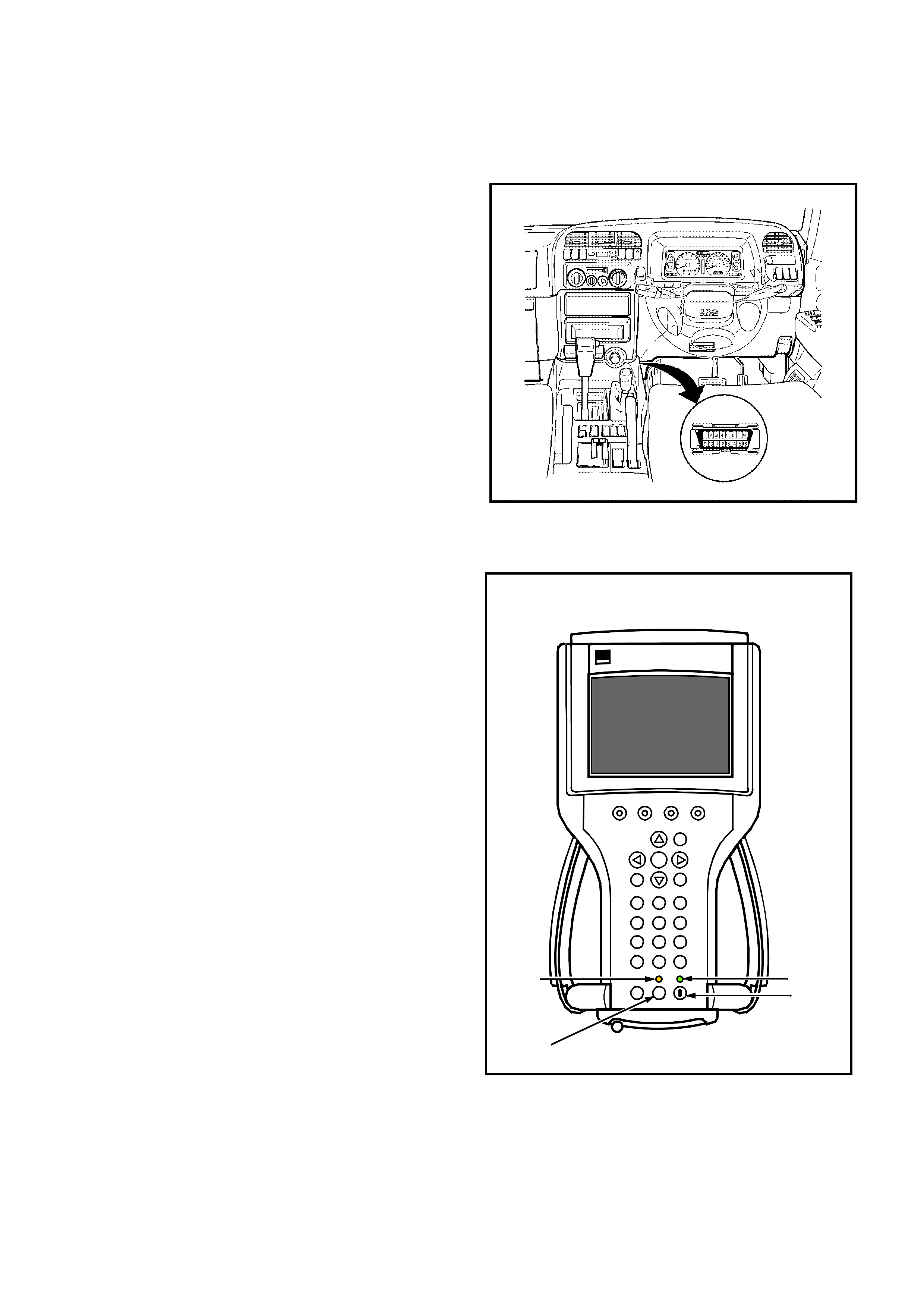
Connecting TECH 2 To The Vehicle
1. Connect Tech 2 to the vehicle DLC, with the DLC
cable and the 16/19 pin adapter.
2. Switch the unit on by pressing the power button (2).
A green light (1) should come on indicating that the
tool is receiving power.
NOTE: At this time the technician should see the Power
On Self Test (POST) run. The POST is a built in
diagnostic self test for the TECH 2 that should find most
common system faults. The POST is run on every
power up to ensure the best operation of the tool. After
the completion of the POST, the TECH 2 unit will briefly
show the POST results. If POST passes, the tool will
continue onto the title screen. If POST fails, results of all
tests will be displayed, and this should show which test
failed. POST failures may be classified as fatal or non-
fatal. A fatal error will not allow the user to continue
using the tool. Failure of the keypad would be an
example of a fatal error. Non-fatal errors found during
the POST will allow continued use of the TECH 2, but
with some limitations. If either a fatal or non-fatal error
occurs, refer to the Troubleshooting section of the
TECH 2 User's Guide.
1. Power Status Indicator Light
2. PWR (Power) Key
3. SHIFT Key
4. SHIFT Key Status Indicator Light
3. At the Tech 2 title screen press the ENTER key to
continue.
PWR
F0
F3
F6
F9
F1
F4
F7
F2
F5
F8
?
GM
TECH 2
2
2
Tech
10 Megabyte
Press [ENTER] to continue
Software Version 11.010
Holden 1997 - 2002
2
1
4
3

4. A selection can be made from the Main Menu,
either by using a function key or by using the arrow
keys to highlight a menu choice and pressing
ENTER.
•NOTE: You will then need to supply some additional
information to the TECH 2. This requires navigation
through a series of lists (called picklists). On some
menus or picklists, the user can use a function key to
make a menu selection, but most of the picklists
require using the selection and action keys. If a
mistake is made in the selection process, or if a
different application or function is desired, press EXIT
to back up one level. Within an application, there may
be soft keys which are available for use. These soft
keys allow access to additional tool functions without
exiting a current tool function. Soft keys are made up
of sets which will appear together. To see the next set
of soft keys, select the More soft key.
The TECH 2 Main Menu contains the following:
F0: Diagnostics
Contains all functions to test, diagnose, monitor and
program the different vehicle systems.
F1: Service Programming System (SPS)
SPS is used in conjunction with Technical
Information System (TIS) 2000 to program vehicle
control units.
F2: View Capture Data
Contains all functions to work with one or two
previously recorded snapshots on one or two
vehicles. This function is to enable the viewing of
captured data without a vehicle.
F3: Tool Options
Contains the TECH 2 self test, set clock, set units,
set screen contrast and Getting Started.
F4: Download/Upload Help
Contains help information on the downloading and
uploading from the TECH 2 to the TIS 2000 CD-
ROM.
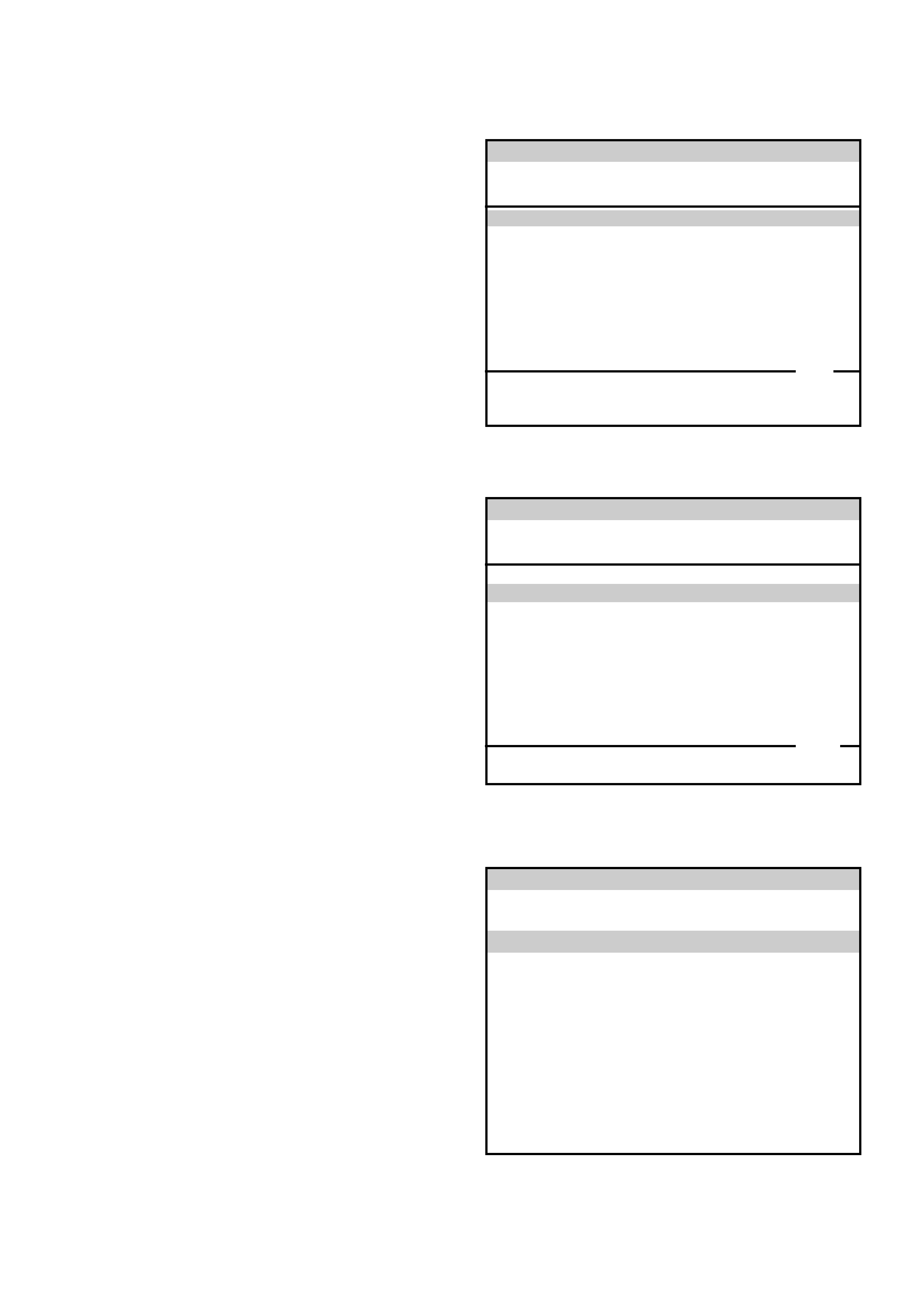
Main Menu
UBS2000a
F0: Diagnostics
F1: Service Programming System (SPS)
F2: View Capture Data
F3: Tool Options
F4: Download/Upload Help
5. Select the correct Model Year with the arrow keys
and the press ENTER. The Vehicle identification
screen will then be displayed.
6. Select the correct Vehicle Type with the arrow keys
and the press ENTER. The System Select Menu
will then be displayed.
7. The desired system can be selected from the
System Select Menu with the function keys or with
arrow keys and then press ENTER.
F0:Powertrain contains all functions to test,
diagnose, and monitor the engine and transmission
systems that communicate with the Tech 2 via the
Powertrain Control Module (PCM).
F1: Chassis contains all functions to test,
diagnose, monitor the vehicles chassis systems;
TOD and ABS modules.
F2: Body contains all functions to test, diagnose,
monitor the instruments and Supplemental
Restraint System.
Main Menu
Select one of the following
Model Year(s)
UBS2001a
(2)
(1)
(Y)
(X)
(W)
(2)
2002
2001
2000
1999
1998
1 / 5
2002
Main Menu
Select one of the following
Vehicle Type(s)
Frontera
Jackaroo
Rodeo
VX Commodore
VU Utility
WH Statesman & Caprice
Corsa-B
Corsa-C
Astra-F
Astra-G
Jackaroo 2 / 10
UBS2001
System Select Menu
(2) 2002 Jackaroo
F0: Powertrain
F1: Chassis
F2: Body
UBS2002
Powertrain Application Menu
1. Select the correct engine from the Vehicle
Identification menu with the arrow keys, then
press ENTER.
2. Turn on the ignition and press the Confirm soft key.
3. The Engine identification screen will then display
the PCM identification information, which will vary
depending upon engine type and software level.
Press the Confirm soft key, the engine application
menu will then be displayed.
NOTE: If Tech 2 is able to communicate with the
PCM the Engine identification information will be
displayed. If Tech 2 is unable to communicate with
the PCM, Tech 2 will display “Waiting for Data”.
The following functions can be selected from the
engine application menu:
F0: Diagnostic Trouble Codes
F1: Data Display
F2: Snapshot
F3: Miscellaneous Tests
F4: Programming
Vehicle Identification
Select one of the following
Powertrain
3.0L L4 4JX1
3.5L V6 6VE1
4L30E
AW30-40LE
3.5L V6 6VE1
2 / 4
UBS2004
Powertrain
(2) 2002 Jackaroo
Electronic System: 3.0L L4 4JX1
Turn Ignition On!
UBS2004h
Confirm
Powertrain
(2) 2002 Jackaroo
Electronic System: 3.0L L4 4JX1
Part Number
Broadcast Code
Identifier
9383459
DJWD
40C
Part Number
UBS2004j
Confirm

3.2L V6 6VE1 ENGINE FUNCTIONS
F0: Diagnostic Trouble Codes
In this test mode, DTCs stored by the PCM can be displayed or cleared. When F0: Diagnostic Trouble Codes is
selected, there are an additional four modes:
F0: Read Current DTC: All current DTC(s) will be displayed.
F1: Clear Current DTC: Clears all current DTC(s) in the PCM memory.
F2: DTC Information: All current DTC(s) will be displayed in numerical order.
F3: Freeze Frame/Failure Records: Freeze Frame is an element of the Diagnostic Management Ssytem which
stores various items of vehicle information at the moment an emissions related DTC is logged in memory and
the MIL is commanded ON.
Failure Records data is an enhancement of Freeze Frame. Failure Records store the same vehicle information
as Freeze Frame, but will store the information when DTC is logged in memory.
F1: Data Display
This mode displays data parameters for the system being diagnosed. When entering this mode, there are three
modes:
F0: Engine Data: In this test mode, the TECH 2 continuously monitors and displays all engine data parameters.
F1: Misfire Data: In this test mode, the TECH 2 continuously monitors the PCM’s “mis-fire counters”. A current and
history misfire counter are maintained for each cylinder. Engine data parameters relevant to the misfire are
displayed along with the misfire counters.
F2: O2 Sensor Data: The Tech 2 continuously monitors and displays engine data parameters.
F2:Snapshot
In this mode, the TECH 2 scan tool captures data before and after a selected snapshot triggering condition which may
or may not set a DTC.
F3:Miscellaneous Tests
In this test mode, the Tech 2 performs software override commands of the PCM, to assist in problem isolation during
diagnostics.
F0: Lamps: The MIL (Malfunction Indicator Lamp) can be commanded on and off.
F1: Relays: The A/C Compressor Clutch relay and the Fuel Pump relay can be commanded on and off.
F2: EVAP: The Cannister Purge Solenoid operation can be commanded between 0% and 99%.
F3: Fuel System: Fuel Trim can be enabled or reset and O2 loop status monitored.
F4: Instruments: Tachometer Control allows the basic operation of the tachometer to be tested.
F5: EGR Control: The EGR Valve operation can be commanded between 0% and 99% in 10% increments.
F6: Variable Intake Manifold Solenoid: Used to command the Variable Intake Manifold Solenoid ON and OFF.
F7:Injector Balance Test: Allows individual injectors to be disabled and the resultant drop in engine RPM to be
monitored.
F4:System Information
In this mode, the TECH 2 displays the status of the Malfunction Indicator Lamp (MIL) and the number of emission
related DTC’s set.

Primary System-Based Diagnostic
Primary System-Based Diagnostic
There are primary system-based diagnostics which
evaluate system operation and its effect on vehicle
emissions. The primary system-based diagnostics are
listed below with a brief description of the diagnostic
function:
Oxygen Sensor Diagnosis
The fuel control heated oxygen sensors (Bank 1 HO2S
1 and Bank 2 HO2S 1) are diagnosed for the following
conditions:
•Inactive signal (output steady at bias voltage –
approx. 450 mV)
•Signal fixed high
•Signal fixed low
If the oxygen sensor pigtail wiring, connector or terminal
are damaged, the entire oxygen sensor assembly must
be replaced. DO NOT attempt to repair the wiring,
connector or terminals. In order for the sensor to
function properly, it must have clean reference air
provided to it. This clean air reference is obtained by
way of the oxygen sensor wire(s). Any attempt to repair
the wires, connector or terminals could result in the
obstruction of the reference air and degrade oxygen
sensor performance. Refer to On-Vehicle Service,
Heated Oxygen Sensors.
Fuel Control Heated Oxygen Sensor
The main function of the fuel control heated oxygen
sensors is to provide the control module with exhaust
stream oxygen content information to allow proper
fueling and maintain emissions within mandated levels.
After it reaches operating temperature, the sensor will
generate a voltage, inversely proportional to the amount
of oxygen present in the exhaust gases. The control
module uses the signal voltage from the fuel control
heated oxygen sensors while in closed loop to adjust
fuel injector pulse width. While in closed loop, the PCM
can adjust fuel delivery to maintain an air/fuel ratio
which allows the best combination of emission control
and driveability.
HO2S Heater
Heated oxygen sensors are used to minimize the
amount of time required for closed loop fuel control to
begin operation and to allow accurate catalyst
monitoring. The oxygen sensor heater greatly
decreases the amount of time required for fuel control
sensors (Bank 1 HO2S 1 and Bank2 HO2S 1) to
become active. Oxygen sensor heaters are required to
maintain a sufficiently high temperature which allows
accurate exhaust oxygen content readings further away
from the engine.
Fuel Trim System Monitor Diagnostic
Operation
Fuel Trim System Monitor Diagnostic
Operation
This system monitors the averages of short-term and
long-term fuel trim values. If these fuel trim values stay
at their limits for a calibrated period of time, a
malfunction is indicated. The fuel trim diagnostic
compares the averages of short-term fuel trim values
and long-term fuel trim values to rich and lean
thresholds. If either value is within the thresholds, a
pass is recorded. If both values are outside their
thresholds, a rich or lean DTC will be recorded.
The fuel trim system diagnostic also conducts an
intrusive test. This test determines if a rich condition is
being caused by excessive fuel vapor from the EVAP
canister. In order to meet OBD requirements, the
control module uses weighted fuel trim cells to
determine the need to set a fuel trim DTC. A fuel trim
DTC can only be set if fuel trim counts in the weighted
fuel trim cells exceed specifications. This means that
the vehicle could have a fuel trim problem which is
causing a problem under certain conditions (i.e., engine
idle high due to a small vacuum leak or rough idle due
to a large vacuum leak) while it operates fine at other
times. No fuel trim DTC would set (although an engine
idle speed DTC or HO2S DTC may set). Use a Tech 2
to observe fuel trim counts while the problem is
occurring.
A fuel trim DTC may be triggered by a number of vehicle
faults. Make use of all information available (other
DTCs stored, rich or lean condition, etc.) when
diagnosing a fuel trim fault.
Fuel Trim Cell Diagnostic Weights
No fuel trim DTC will set regardless of the fuel trim
counts in cell 0 unless the fuel trim counts in the
weighted cells are also outside specifications. This
means that the vehicle could have a fuel trim problem
which is causing a problem under certain conditions (i.e.
engine idle high due to a small vacuum leak or rough
due to a large vacuum leak) while it operates fine at
other times. No fuel trim DTC would set (although an
engine idle speed DTC or HO2S DTC may set). Use a
Tech 2 to observe fuel trim counts while the problem is
occurring.
On-Board Diagnostic (OBD) System Check
TS321119
Circuit Description
The on-board diagnostic system check is the starting
point for any driveability complaint diagnosis. Before
using this procedure, perform a careful visual/physical
check of the PCM and engine grounds for cleanliness
and tightness.
The on-board diagnostic system check is an organized
approach to identifying a problem created by an
electronic engine control system malfunction.
Diagnostic Aids
An intermittent may be caused by a poor connection,
rubbed-through wire insulation or a wire broken inside
the insulation. Check for poor connections or a
damaged harness. Inspect the PCM harness and
connector for improper mating, broken locks,
improperly formed or damaged terminals, poor
terminal-to-wire connection, and damaged harness.
Test Description
Number(s) below refer to the step number(s) on the
Diagnostic Chart:
1. The MIL (“Check Engine”lamp) should be “ON”
steady with the ignition “ON”/engine “OFF.” If not,
Chart A-1 should be used to isolate the malfunction.
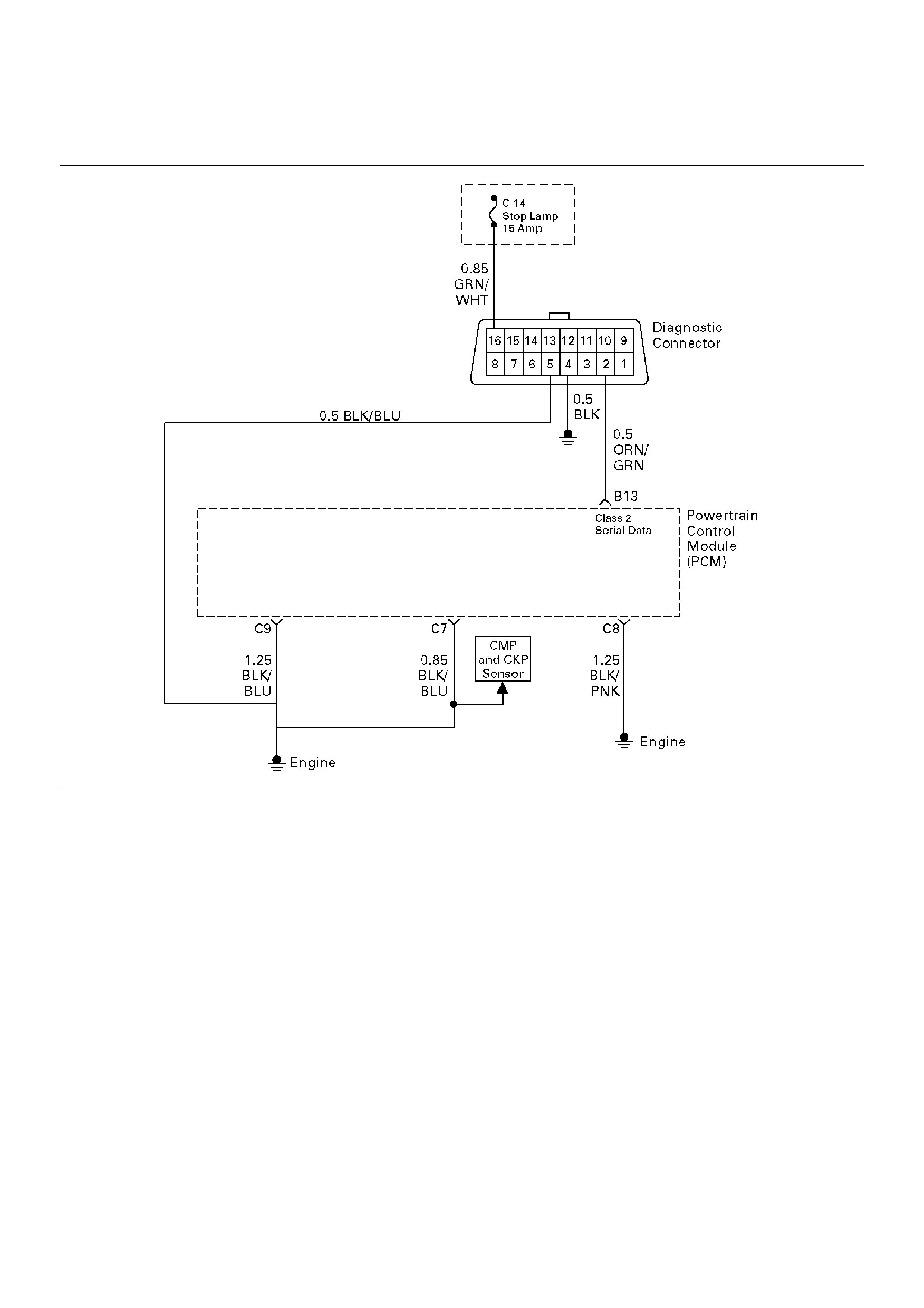
2. Checks the Class 2 data circuit and ensures that the
PCM is able to transmit serial data.
3. This test ensures that the PCM is capable of
controlling the MIL (“Check Engine”lamp) and the
MIL (“Check Engine”lamp) driver circuit is not
shorted to ground.
4. If the engine will not start, the Cranks But Will Not
Run chart should be used to diagnose the condition.
7. A Tech 2 parameter which is not within the typical
range may help to isolate the area which is causing
the problem.
Important: 10. This vehicle is equipped with a PCM
which utilizes an electrically erasable programmable
read only memory (EEPROM). The replacement PCM
must be programmed. Refer to Sections OC1 Service
Programming System and 11A1 6VE1 Immobiliser.

On-Board Diagnostic (OBD) System Check
StepActionValue(s)YesNo
1 1.Ignition “ON,” engine “OFF.”
2.Observe the malfunction indicator lamp (MIL or
“Check Engine” lamp).
Is the MIL (“Check Engine”lamp)“ON?” —Go to Step 2
Go to No MIL
(“Check
Engine”lamp)
2 1.Ignition “OFF.”
2.Install a Tech 2.
3.Ignition “ON.”
4.Attempt to display PCM engine data with the Tech
2.
Does the Tech 2 display PCM data?—Go to Step 3Go to Step 8
3 1.Using the Tech 2 output tests function, select MIL
(“Check Engine”lamp) dash lamp control and
command the MIL (“Check Engine”lamp) “OFF.”
2.Observe the MIL (“Check Engine”lamp).
Did the MIL (“Check Engine”lamp) turn “OFF?”
3.Push the QUIT softkey to exit the test. (see
Note 1)—Go to Step 4
Go to MIL
(“Check
Engine”lamp)
On Steady
4 Attempt to start the engine.
Did the engine start and continue to run?
—Go to Step 5
Go to Cranks
But Will Not
Run
5 Select “Display DTCs” with the Tech 2.
Are any DTCs stored?—Go to Step 6Go to Step 7
6 Are two or more of the following DTCs stored?
P0107, P0108, P0113, P0118, P0122, P0123,
P0712.?
—
Go to “Multiple
PCM
Information
Sensor DTCs
Set”
Go to
applicable DTC
table
7 Compare PCM data values displayed on the Tech 2 to
the typical engine scan data values.
Are the displayed values normal or close to the typical
values?—
Refer toTypical
scan data value
Refer to
indicated
Component
System Checks
8 1.Ignition “OFF,” disconnect the PCM.
2.Ignition “ON,” engine “OFF.”
3.Check the Class 2 data circuit for an open, short
to ground, or short to voltage. Also, check the
DLC ignition feed circuit for an open or short to
ground and the DLC ground circuit for an open.
4.If a problem is found, repair as necessary.
Was a problem found?—Go to Step 2Go to Step 9
9 Attempt to display PCM data with the Tech 2.
Does the Tech 2 display PCM engine data?—Go to Step 2Go to Step 10
10 Replace the PCM.
Important: The replacement PCM must be
programmed. Refer to Sections OC1 Service
Programming System and 11A1 6VE1 Immobiliser.
Important: Is the action complete?—Go to Step 2 —
Note 1
Failure to exit the MIL test at Step 3 with the “QUIT” softkey may result in a false DTC P1850 -
“Band Apply Solenoid Failure” being set in the PCM.
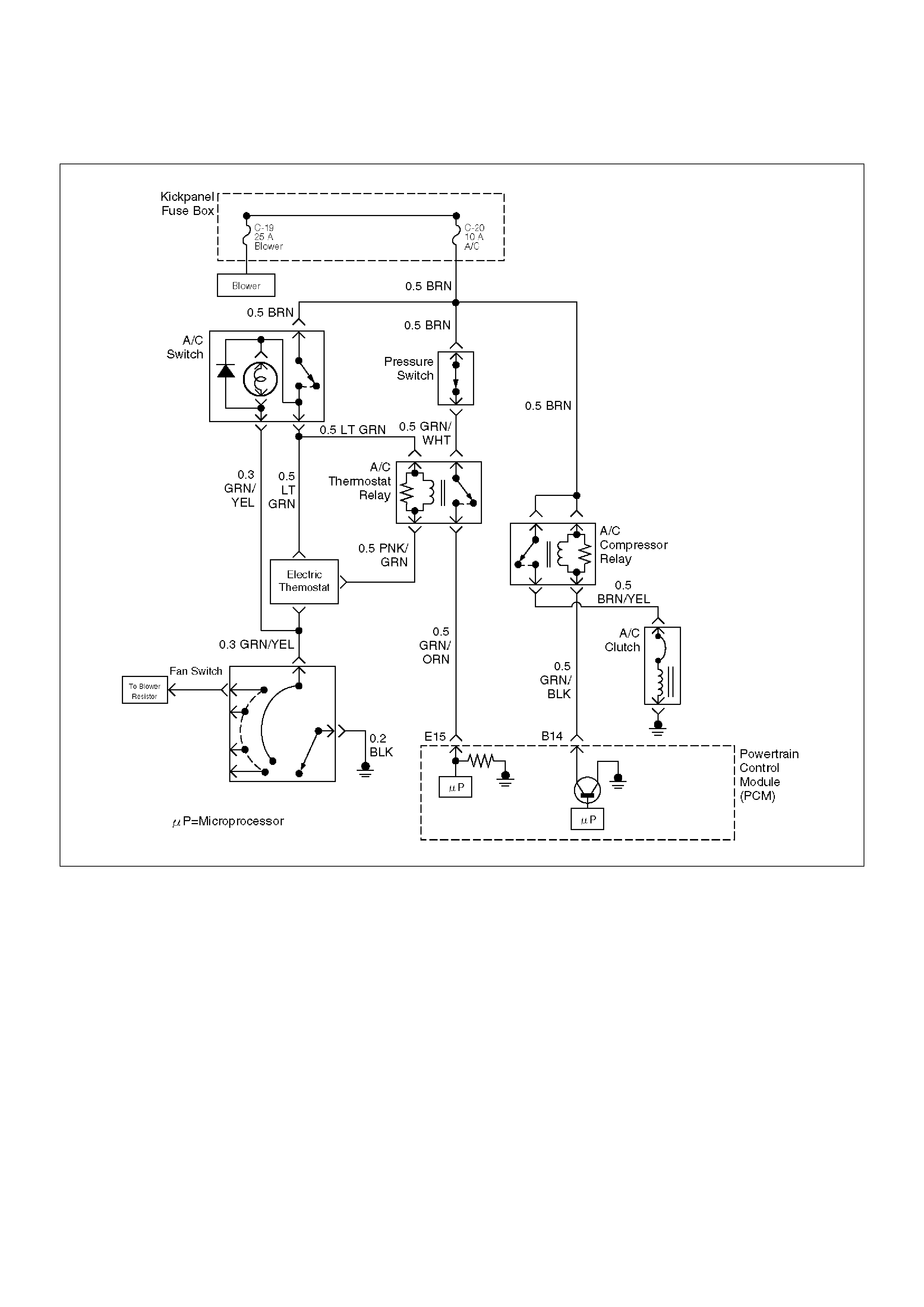
A/C Clutch Control Circuit Diagnosis
D06RW085
Circuit Description
When air conditioning and blower fan are selected, and
if the system has a sufficient refrigerant charge, a
12-volt signal is supplied to the A/C request input of the
powertrain control module (PCM). The A/C request
signal may be temporarily canceled during system
operation by the electronic thermostat in the evaporator
case. The electronic thermostat may intermittently
remove the control circuit ground for the A/C thermostat
relay to prevent the evaporator from forming ice. When
the A/C request signal is received by the PCM, the PCM
supplies a ground from the compressor clutch relay if
the engine operating conditions are within acceptable
ranges. With the A/C compressor relay energized,
voltage is supplied to the compressor clutch coil.
The PCM will enable the compressor clutch to engage
whenever A/C has been selected with the engine
running, unless any of the following conditions are
present:
• The throttle is greater than 90%.
• The ignition voltage is below 10.5 volts.
• The engine speed is greater than 4500 RPM for 5
seconds or 5400 RPM.
• The engine coolant temperature (ECT) is greater
than 125 °C (257 °F).
• The intake air temperature (IAT) is less than 5°C
(41°F).
• The power steering pressure switch signals a
cramped position.
Diagnostic Aids
To diagnose an the intermittent fault, check for the
following conditions:
• Poor connection at the PCM–Inspect connections for

backed-out terminals, improper mating, broken locks,
improperly formed or damaged terminals, and poor
terminal-to-wire connection.
•Damaged harness–Inspect the wiring harness for
damage. If the harness appears to OK, observe the
A/C clutch while moving connectors and wiring
harnesses related to the A/C. A sudden clutch
malfunction will indicate the source of the intermittent
fault.
A/C Clutch Diagnosis
This chart should be used for diagnosing the electrical
portion of the A/C compressor clutch circuit. A Tech 2
will be used in diagnosing the system. The Tech 2 has
the ability to read the A/C request input to the PCM.
The Tech 2 can display when the PCM has commanded
the A/C clutch “ON.” The Tech 2 should have the ability
to override the A/C request signal and energize the A/C
compressor relay.
Test Description
Important: Do not engage the A/C compressor clutch
with the engine running if an A/C mode is not selected
at the A/C control switch.
The numbers below refer to the step numbers on the
Diagnostic Chart:
3. This a test determine is the problem is with the
refrigerant system. If the switch is open, A/C
pressure gauges will be used to determine if the
pressure switch is faulty or if the system is partially
discharged or empty.
4. Although the normal complaint will be the A/C clutch
failing to engage, it is possible for a short circuit to
cause the clutch to run when A/C has not been
selected. This step is a test for that condition.
7. There is an extremely low probability that both relays
will fail at the same time, so the substitution process
is one way to check the A/C Thermostat relay. Use a
known good relay to do a substitution check.
9. The blower system furnishes a ground for the A/C
control circuit, and it also shares a power source
through the Heater and A/C Relay. The blower must
be “ON” in order to test the A/C system.
A/C Clutch Control Circuit Diagnosis
StepActionValue(s)YesNo
1 Was the “On-Board Diagnostic (OBD) System Check”
performed?—Go to Step 2
Go to OBD
System Check
2 Are any other DTCs stored?
—
Go to the other
DTC chart(s)
firstGo to Step 3
3 1.Disconnect the electrical connector at the
pressure switch located on the receiver/drier.
2.Use an ohmmeter to check continuity across the
pressure switch.
Is the pressure switch open? —
Go to Air
Conditioning to
diagnose the
cause of the
open pressure
switchGo to Step 4
4 Important: Before continuing with the diagnosis, the
following conditions must be met:
• The intake air temperature must be greater than
15°C. (60°F).
• The engine coolant temperature must be less than
119°C (246°F).
1. A/C “OFF.”
2. Start the engine and idle for 1 minute.
3. Observe the A/C compressor.
Is the A/C compressor clutch engaged even though A/
C has not been requested? — Go to Step 45 Go to Step 5
5 1. Idle the engine.
2. A/C“ON”.
3. Blower“ON”.
4. Observe the A/C compressor.
Is the A/C compressor magnetic clutch engaged? —
Refer to
Diagnostic Aids Go to Step 6

6 1. Engine idling.
2. A/C“ON”.
3. Blower“ON”.
4. Observe the “A/C Request” display on the Tech 2.
Does the tool “A/C Request” display indicate “Yes?” — Go to Step 34 Go to Step 7
7 Temporarily substitute the A/C compressor relay in
place of the A/C thermostat relay, then repeat Step 5.
Did the “A/C Request” display indicate “Yes?” — Go to Step 8 Go to Step 9
8 Replace the original A/C thermostat relay.
Is the action complete? — Verify repair —
9 Dose the blower operate? — Go to Step 10 Go to Step 11
10 Repair the blower.
Is the action complete? — Verify repair —
11 Check for a faulty 10a A/C fuse in the underdash fuse
panel.
Was the 10A fuse OK? — Go to Step 13 Go to Step 12
12 Check for short circuit and make repairs if necessary.
Replace the 10A A/C fuse.
Is the action complete? — Verify repair —
13 1. Ignition “ON.”
2. Use a DVM to check voltage at the positive A/C
switch wire (BRN).
Was voltage equal to the specified value? +B Go to Step 15 Go to Step 14
14 Repair the open wire (BRN) between the A/C switch
and the A/C fuse.
Is the action complete? — Verify repair —
15 1. Remove the glove box to gain access to the A/C
thermostat.
2. Disconnect the thermostat connector.
3. Attach a fused jumper between ground and the
PNK/GRN wire at the thermostat.
4. A/C “ON.”
5. Blower “ON.”
Dose A/C request indicate “YES” on the Tech 2? — Go to Step 16 Go to Step 23
16 1. Ignition “ON.”
2. Use a DVM to check voltage at the electronic A/C
thermostat.
Was voltage equal to the specified value? +B Go to Step 20 Go to Step 17
17 Check for an open (LT GRN) between the thermostat
and the A/C switch.
Was the wire open? — Go to Step 18 Go to Step 19
18 Repair the open wire (LT GRN) between the
thermostat and the A/C switch.
Is the action complete? — Verify repair —
19 Replace the A/C switch.
Is the action complete? — Verify repair —
20 Use an ohmmeter to check continuity between the
electronic A/C thermostat and the blower switch.
Was there an open circuit? — Go to Step 21 Go to Step 22
Step Action Value(s) Yes No

21 Repair the open wire (GRN/YEL) between the
thermostat and the blower switch.
Is the action complete?—Verify repair—
22 Replace the electronic A/C thermostat.
Is the an action complete?—Verify repair—
23 Check for an open circuit between A/C thermostat
relay and PCM A/C request terminal (E-15).
Was there an open circuit?—Go to Step 24Go to Step 25
24 Repair the open circuit between the PCM and A/C
thermostat relay.
Is the action complete?—Verify repair—
25 Check for an open circuit between the A/C switch (LT
GRN) and the A/C thermostat relay (LT GRN).
Was there an open circuit?—Go to Step 26Go to Step 27
26 Repair the open circuit between the A/C switch and
the A/C thermostat relay.
Is the action complete?—Verify repair—
27 1.Ignition “ON.”
2.Use a DVM to check voltage at the A/C pressure
switch (BRN).
Was voltage equal to the specified value?+BGo to Step 29Go to Step 28
28 Repair the open circuit between the 10A A/C fuse and
the pressure switch.
Is the action complete?—Verify repair—
29 Use an ohmmeter to check continuity between the
pressure switch (GRN/WHT) and the A/C thermostat
relay (GRN/WHT).
Was the circuit open?—Go to Step 30Go to Step 31
30 Repair the open circuit between the pressure switch
and the A/C thermostat relay.
Is the action complete?—Verify repair—
31 Check for damaged pin or terminal at E-15 of the
PCM.
Was a damaged pin or terminal found?—Go to Step 32Go to Step 33
32 Repair the damaged pin or terminal.
Is the action complete?—Verify repair—
33 Replace the PCM.
Important: The replacement PCM must be
programmed. Refer to Sections OC1 Service
Programming System and 11A1 6VE1 Immobiliser.
Is the action complete? — Verify repair —
34 1. Remove the A/C compressor relay.
2. Ignition “ON.”
3. Use a DVM to check voltage at both of the BRN
wires at the A/C compressor relay socket.
Is the voltage equal to the specified value? +B Go to Step 36 Go to Step 35
35 Repair the faulty BRN wire between the A/C fuse and
the A/C compressor relay .
Is the action complete? — Verify repair —
Step Action Value(s) Yes No

36 1. A/C compressor relay removed.
2. Engine idling.
3. A/C “ON.”
4. Blower “ON.”
5. Use a DVM to measure voltage between the GRN/
BLK wire at the A/C compressor relay socket and
battery±.
Did the DVM indicate the specified value? +B Go to Step 40 Go to Step 37
37 Check for an open GRN/BLK wire between PCM
terminal B-14 and the A/C compressor relay.
Was the wire open? — Go to Step 38 Go to Step 39
38 Repair the open GRN/BLK wire between the PCM and
the A/C compressor relay.
Is the action complete? — Verify repair —
39 Check for a damaged pin or terminal at B-14 of the
PCM.
Was a damaged pin or a terminal found? — Go to Step 32 Go to Step 33
40 1. A/C compressor relay removed.
2. Connect a fused jumper at the A/C compressor
relay socket between either BRN wire and the
BRN/YEL wire.
3. Engine idling.
4. A/C “ON.”
5. Blower “ON.”
Did the compressor magnetic clutch engage? — Go to Step 41 Go to Step 42
41 Repair the A/C compressor relay.
Is the action complete? — Verify repair —
42 Check for an open circuit between the A/C
compressor relay and the A/C clutch.
Was an open circuit found? — Go to Step 43 Go to Step 44
43 Repair the open circuit between the compressor
Clutch and the A/C compressor relay.
Is the action complete? — Verify repair —
44 Service the compressor clutch or replace the
compressor due to a faulty internal overheat switch.
Is the action complete? — Verify repair —
45 1. Remove the A/C compressor relay.
2. Idle the engine.
Is the compressor clutch still engaged when A/C is not
selected? — Go to Step 46 Go to Step 47
46 Repair the short to voltage between the A/C clutch
and A/C compressor relay.
Is the action complete? — Verify repair —
47 1. Reinstall the A/C compressor relay.
2. Remove the A/C thermostat relay.
3. Engine idling.
Is the compressor clutch still engaged when A/C is not
selected? — Go to Step 48 Go to Step 50
48 Use a DVM to check for a short to ground between the
A/C compressor relay and B-14 of the PCM.
Was a short detected? — Go to Step 49 Go to Step 33
Step Action Value(s) Yes No

49 Repair the short to ground between the PCM and A/C
compressor relay.
Is the action complete? — Verify repair —
50 Repair the short to ground between the A/C
thermostat relay and the electronic thermostat.
Is the action complete? — Verify repair —
Step Action Value(s) Yes No
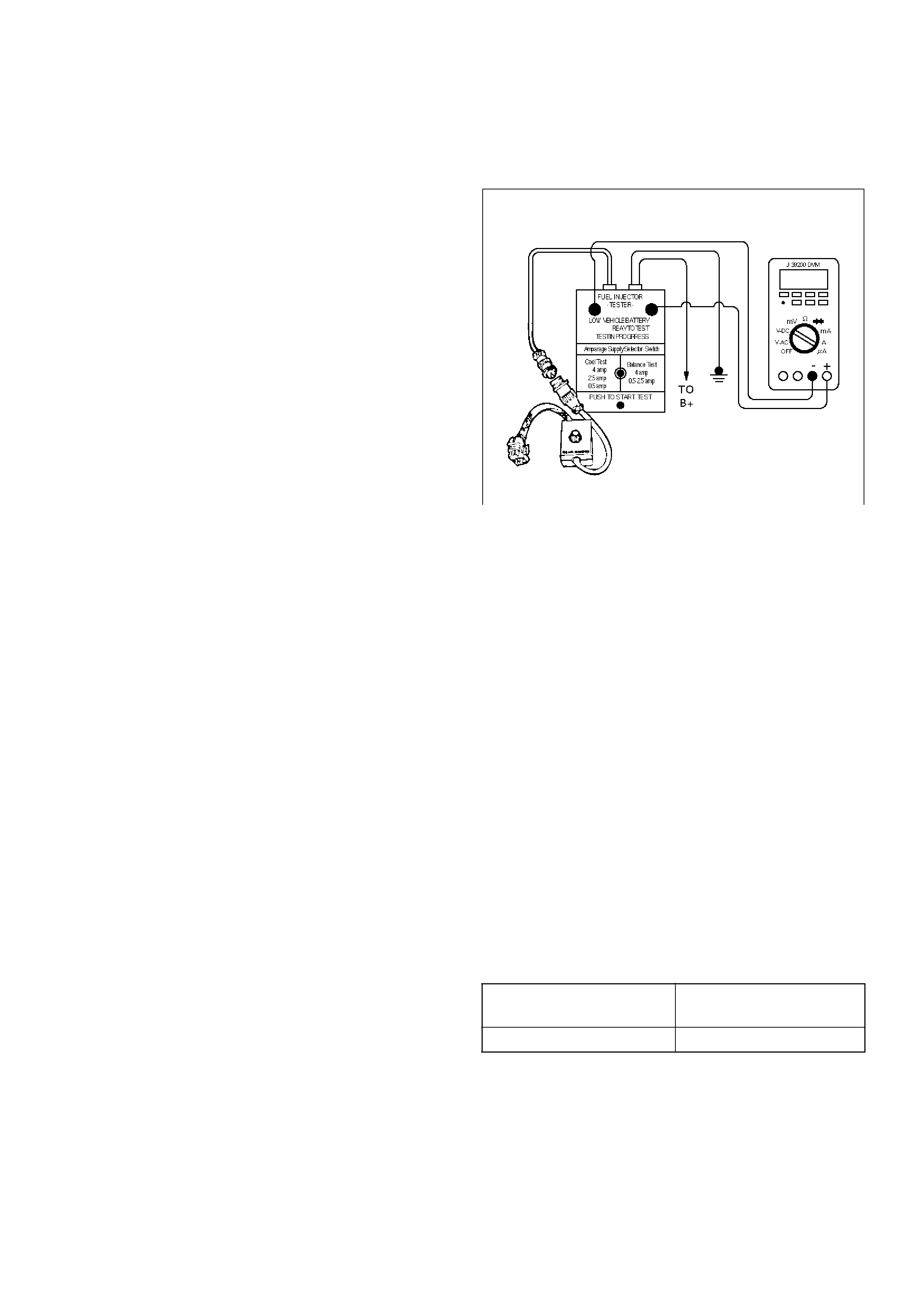
Electronic Ignition System Diagnosis
If the engine cranks but will not run or immediately
stalls, the Engine Cranks But Will Not Start chart must
be used to determine if the failure is the ignition system
or the fuel system. If DTC P0341, or P0336 is set, the
appropriate diagnostic trouble code chart must be used
for diagnosis.
If a misfire is being experienced with no DTC set, refer
to the Symptoms section for diagnosis.
Fuel Metering System Check
Some failures of the fuel metering system will result in
an “Engine Cranks But Will Not Run” symptom. If this
condition exists, refer to the Cranks But Will Not Run
chart. This chart will determine if the problem is caused
by the ignition system, the PCM, or the fuel pump
electrical circuit.
Refer to Fuel System Electrical Test for the fuel system
wiring schematic.
If there is a fuel delivery problem, refer to Fuel System
Diagnosis, which diagnoses the fuel injectors, the fuel
pressure regulator, and the fuel pump. If a malfunction
occurs in the fuel metering system, it usually results in
either a rich HO2S signal or a lean HO2S signal. This
condition is indicated by the HO2S voltage, which
causes the PCM to change the fuel calculation (fuel
injector pulse width) based on the HO2S reading.
Changes made to the fuel calculation will be indicated
by a change in the long term fuel trim values which can
be monitored with a Tech 2. Ideal long term fuel trim
values are around 0%; for a lean HO2S signal, the PCM
will add fuel, resulting in a fuel trim value above 0%.
Some variations in fuel trim values are normal because
all engines are not exactly the same. If the fuel trim
values are greater than +23%, refer to DTC P0131,
DTC P0151, DTC P0171, and DTC 1171 for items
which can cause a lean HO2S signal.
Idle Air Control (IAC) Valve
The Tech 2 displays the IAC pintle position in counts. A
count of “0” indicates the PCM is commanding the IAC
pintle to be driven all the way into a fully-seated
position. This is usually caused by a large vacuum leak.
The higher the number of counts, the more air is being
commanded to bypass the throttle blade. Refer to IAC
System Check in order to diagnose the IAC system.
Refer to Rough, Unstable, or Incorrect Idle, Stalling in
Symptoms for other possible causes of idle problems.
Fuel System Pressure Test
A fuel system pressure test is part of several of the
diagnostic charts and symptom checks. To perform this
test, refer to Fuel Systems Diagnosis.
Fuel Injector Coil Test Procedure and
Fuel Injector Balance Test Procedure
T32003
Test Description
Number(s) below refer to the step number(s) on the
Diagnostic Chart:
2. Relieve the fuel pressure by connecting the
5-8840-0378-0 Fuel Pressure Gauge to the fuel
pressure connection on the fuel rail.
CAUTION: In order to reduce the risk of fire and
personal injury, wrap a shop towel around the fuel
pressure connection. The towel will absorb any
fuel leakage that occurs during the connection of
the fuel pressure gauge. Place the towel in an
approved container when the connection of the fuel
pressure gauge is complete.
Place the fuel pressure gauge bleed hose in an
approved gasoline container.
With the ignition switch “OFF,” open the valve on the
fuel pressure gauge.
3. Record the lowest voltage displayed by the DVM
after the first second of the test. (During the first
second, voltage displayed by the DVM may be
inaccurate due to the initial current surge.)
Injector Specifications:
• The voltage displayed by the DVM should be
within the specified range.
• The voltage displayed by the DVM may increase
throughout the test as the fuel injector windings
warm and the resistance of the fuel injector
windings changes.
• An erratic voltage reading (large fluctuations in
voltage that do not stabilize) indicates an
intermittent connection within the fuel injector.
Resistance Ohms Voltage Specification at
10°C-35°C (50°F-95°F)
11.8 – 12.6 5.7 – 6.6
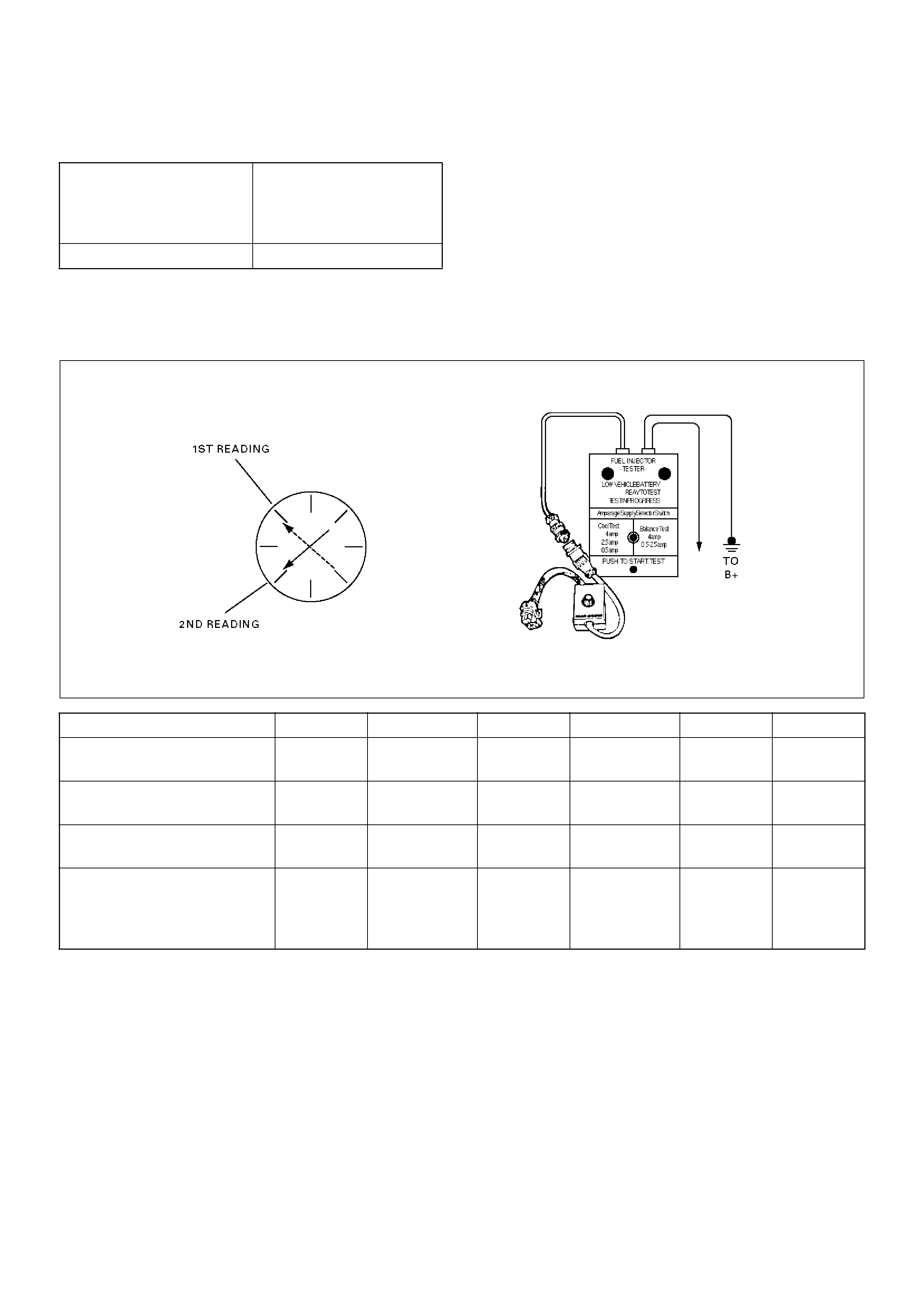
5. Injector Specifications: 7. The Fuel Injector Balance Test portion of this chart
(Step 7 through Step 11) checks the mechanical (fuel
delivery) portion of the fuel injector. An engine
cool-down period of 10 minutes is necessary in order
to avoid irregular fuel pressure readings due to “Hot
Soak” fuel boiling.
Injector Coil Test Procedure (Steps 1-6) and Injector Balance Test Procedure
(Steps 7-11)
R262001
NOTE: These figures are examples only.
Highest Acceptable
Voltage Reading Above/
Below 35°C/10°C (95°F/
50°F)
Acceptable Subtracted
Value
9.5 Volts 0.6 Volts
CYLINDER 1 2 3 4 5 6
1st Reading (1) 296kPa
(43psi)
296kPa
(43psi)
296kPa
(43psi)
296kPa
(43psi)
296kPa
(43psi)
296kPa
(43psi)
2nd Reading (2) 131kPa
(19psi)
117 kPa
(17psi)
124kPa
(18psi)
145kPa
(21psi)
131kPa
(19psi)
130kPa
(19psi)
Amount of Drop (1st
Reading–2nd Reading)
165kPa
(24psi)
179kPa
(26psi)
172kPa
(25psi)
151kPa
(22psi)
165kPa
(24psi)
166kPa
(24psi)
Av.drop = 166 kPa/24 psi ±
10 kPa/1.5 psi
= 156–176 kPa or 22.5–
25.5psi
OK Faulty, Rich
(Too Much
Fuel Drop)
OK Faulty, Lean
(Too Little
Fuel Drop)
OK OK

Injector Coil Test Procedure (Steps 1-6) and Injector Balance Test Procedure (Steps 7-11)
StepActionValue(s)YesNo
1 Was the “On-Board Diagnostic (OBD) System Check”
performed?—Go to Step 2
Go to OBD
System Check
2 1.Turn the engine “OFF.”
NOTE: In order to prevent flooding of a single cylinder
and possible engine damage, relieve the fuel pressure
before performing the fuel injector coil test procedure.
2.Relieve the fuel pressure. Refer to Test
Description Number 2.
3.Connect the 5-8840-2638-0 Fuel Injector Tester to
B+ and ground, and to the 5-8840-2619-0 Injector
Switch Box.
4.Connect the injector switch box to the grey fuel
injector harness connector located on the front of
the EVAP canister bracket.
5.Set the amperage supply selector switch on the
fuel injector tester to the “Coil Test” 0.5 amp
position.
6.Connect the leads from the 5-8840-0285-0 Digital
Voltmeter (DVM) to the injector tester. Refer to
the illustrations associated with the test
description.
7.Set the DVM to the tenths scale (0.0).
8.Observe the engine coolant temperature.
Is the engine coolant temperature within the specified
values?
10°C (50°F)
to 35°C
(95°F)Go to Step 3Go to Step 5
3 1.Set injector switch box injector #1.
2.Press the “Push to Start Test” button on the fuel
injector tester.
3.Observe the voltage reading on the DVM.
Important: The voltage reading may rise during the
test.
4. Record the lowest voltage observed after the first
second of the test.
5. Set the injector switch box to the next injector and
repeat steps 2, 3, and 4.
Did any fuel injector have an erratic voltage reading
(large fluctuations in voltage that did not stabilize) or a
voltage reading outside of the specified values? 5.7-6.6 V Go to Step 4 Go to Step 7
4 Replace the faulty fuel injector(s). Refer to Fuel
Injector.
Is the action complete? — Go to Step 7 —

5 1.Set injector switch box injector #1.
2.Press the “Push to Start Test” button on the fuel
injector tester.
3.Observe the voltage reading on the DVM.
Important: The voltage reading may rise during the
test.
4.Record the lowest voltage observed after the first
second of the test.
5.Set the injector switch box to the next injector and
repeat steps 2, 3, and 4.
Did any fuel injector have an erratic voltage reading
(large fluctuations in voltage that did not stabilize) or a
voltage reading above the specified value?9.5 VGo to Step 4Go to Step 6
6 1.Identify the highest voltage reading recorded
(other than those above 9.5 V).
2.Subtract the voltage reading of each injector from
the highest voltage selected in step 1. Repeat
until you have a subtracted value for each injector.
For any injector, is the subtracted Value in step 2
greater than the specified value?0.6 VGo to Step 4Go to Step 7
7 CAUTION: In order to reduce the risk of fire and
personal injury, wrap a shop towel around the fuel
pressure connection. The towel will absorb any
fuel leakage that occurs during the connection of
the fuel pressure gauge. Place the towel in an
approved container when the connection of the
fuel pressure gauge is complete.
1. Connect the 5-8840-0378-0 Fuel Pressure Gauge
to the fuel pressure test port.
2. Energize the fuel pump using the scan tool.
3. Place the bleed hose of the fuel pressure gauge
into an approved gasoline container.
4. Bleed the air out of the fuel pressure gauge.
5. With the fuel pump running, observe the reading
on the fuel pressure gauge.
Is the fuel pressure within the specified values?
296-376kPa
(43-55psi) Go to Step 8
Go to Fuel
System
Diagnosis
8 Turn the fuel pump “OFF.”
Does the fuel pressure remain constant?
—Go to Step 9
Go to Fuel
System
Diagnosis
Step Action Value(s) Yes No

9 1. Connect the 5-8840-2638-0 Fuel Injector Tester
and 5-8840-2619-0 Injector Switch Box the fuel
injector harness connector.
2. Set the amperage supply selector switch on the
fuel injector tester to the “Balance Test” 0.5–2.5
amp position.
3. Using the scan tool turn the fuel pump “ON” then
“OFF” in order to pressurize the fuel system.
4. Record the fuel pressure indicated by the fuel
pressure gauge after the fuel pressure stabilizes.
This is the first pressure reading.
5. Energize the fuel injector by depressing the “Push
to Start Test” button on the fuel injector tester.
6. Record the fuel pressure indicated by the fuel
pressure gauge after the fuel pressure gauge
needle has stopped moving. This is the second
pressure reading.
7. Repeat steps 1 through 6 for each fuel injector.
8. Subtract the second pressure reading from the
first pressure reading for one fuel injector. The
result is the pressure drop value.
9. Obtain a pressure drop value for each fuel injector.
10. Add all of the individual pressure drop values.
This is the total pressure drop.
11. Divide the total pressure drop by the number of
fuel injectors. This is the average pressure drop.
Does any fuel injector have a pressure drop value that
is either higher than the average pressure drop or
lower than the average pressure drop by the specified
value?
10kPa
(1.5psi) Go to Step 10
Go to OBD
System Check
10 Re-test any fuel injector that does not meet the
specification. Refer to the procedure in step 11.
NOTE: Do not repeat any portion of this test before
running the engine in order to prevent the engine from
flooding.
Does any fuel injector still have a pressure drop value
that is either higher than the average pressure drop or
lower than the average pressure drop by the specified
value?
10kPa
(1.5psi) Go to Step 11
Go to
Symptoms
11 Replace the faulty fuel injector(s). Refer to Fuel
Injector.
Is the action complete? — Verify repair —
Step Action Value(s) Yes No

Knock Sensor Diagnosis
The Tech 2 has two data displays available for
diagnosing the knock sensor (KS) system. The two
displays are described as follows:
•“Knock Retard” indicates the number of degrees that
the spark timing is being retarded due to a knock
condition.
•“KS Noise Channel” indicates the current voltage
level being monitored on the noise channel.
DTCs P0325 and P0327 are designed to diagnose the
KS module, the knock sensor, and the related wiring.
The problems encountered with the KS system should
set a DTC. However, if no DTC was set but the KS
system is suspect because of a detonation complaint,
refer to Detonation/Spark Knock in Symptoms.
Powertrain Control Module (PCM)
Diagnosis
To read and clear diagnostic trouble codes, use a Tech
2.
Important: Use of a Tech 2 is recommended to clear
diagnostic trouble codes from the PCM memory.
Diagnostic trouble codes can also be cleared by turning
the ignition “OFF” and disconnecting the battery power
from the PCM for 30 seconds. Turning off the ignition
and disconnecting the battery power from the PCM will
cause all diagnostic information in the PCM memory to
be cleared. Therefore, all the diagnostic tests will have
to be re-run.
Since the PCM can have a failure which may affect only
one circuit, following the diagnostic procedures in this
section will determine which circuit has a problem and
where it is.
If a diagnostic chart indicates that the PCM connections
or the PCM is the cause of a problem, and the PCM is
replaced, but this does not correct the problem, one of
the following may be the reason:
•There is a problem with the PCM terminal
connections. The terminals may have to be removed
from the connector in order to check them properly.
•The problem is intermittent. This means that the
problem is not present at the time the system is being
checked. In this case, refer to the Symptoms portion
of the manual and make a careful physical inspection
of all component and wiring associated with the
affected system.
•There is a shorted solenoid, relay coil, or harness.
Solenoids and relays are turned “ON” and “OFF” by
the PCM using internal electronic switches called
drivers. A shorted solenoid, relay coil, or harness will
not damage the PCM but will cause the solenoid or
relay to be inoperative.
Multiple PCM Information Sensor
DTCS Set
Circuit Description
The powertrain control module (PCM) monitors various
sensors to determine the engine operating conditions.
The PCM controls fuel delivery, spark advance,
transmission operation, and emission control device
operation based on the sensor inputs.
The PCM provides a sensor ground to all of the
sensors. The PCM applies 5 volts through a pull-up
resistor, and determines the status of the following
sensors by monitoring the voltage present between the
5-volt supply and the resistor:
•The engine coolant temperature (ETC) sensor
•The intake air temperature (IAT) sensor
•The transmission fluid temperature (TFT) sensor
The PCM provides the following sensors with a 5-volt
reference and a sensor ground signal:
•The exhaust gas recirculating (EGR) pintle position
sensor
•The throttle position (TP) sensor
•The manifold absolute pressure (MAP) sensor
The PCM monitors the separate feedback signals from
these sensors in order to determine their operating
status.
Diagnostic Aids
Important: Be sure to inspect PCM and engine
grounds for being secure and clean.
A short to voltage in one of the sensor input circuits may
cause one or more of the following DTCs to be set:
•P0108
•P0113
•P0118
•P0123
•P0560
•P0712
•P0406
Important: If a sensor input circuit has been shorted to
voltage, ensure that the sensor is not damaged. A
damaged sensor will continue to indicate a high or low
voltage after the affected circuit has been repaired. If
the sensor has been damaged, replace it.
An open in the sensor ground circuit between the PCM
and the splice will cause one or more of the following
DTCs to be set:
• P0108
•P0113
•P0118
• P0123
• P0712
• P0406

A short to ground in the 5-volt reference A or B circuit
will cause one or more of the following DTCs to be set:
•P0107
•P0122
In the 5-volt reference circuit A, between the PCM and
the splice, will cause one or more of the following DTCs
to be set:
•P0122
In the 5-volt reference circuit B, between the PCM and
the splice, will cause one or more of the following DTCs
to be set:
•P0107
Check for the following conditions:
•Poor connection at PCM.
Inspect the harness connectors for backed-out
terminals, improper mating, broken locks, improperly
formed or damage terminals, and a poor
terminal-to-wire connection.
•Damaged harness.
Inspect the wiring harness for damage. If the
harness is not damaged, observe an affected
sensor's displayed value on the Tech 2 with the
ignition “ON” and the engine “OFF” while you move
the connectors and the wiring harnesses related to
the following sensors:
•IAT
•ECT
•TP
•MAP
•EGR
•TFT
Multiple PCM Information Sensor DTCs Set
StepActionValue(s)YesNo
1 Was the “On-Board Diagnostic (OBD) System Check”
performed? — Go to Step 2
Go to OBD
System Check
2 1. Turn the ignition “OFF,” disconnect the PCM.
2. Turn the ignition “ON,” check the 5 volt reference
A circuit for the following conditions:
• A poor connection at the PCM.
• An open between the PCM connector and the
splice.
• A short to ground.
• A short to voltage.
Is there an open or short? — Go to Step 3 Go to Step 4
3 Repair the open or short.
Is the action complete? — Verify repair —
4 Check the sensor ground circuit for the following
conditions:
• A poor connection at the PCM or the affected
sensors.
• An open between the PCM connector and the
affected sensors.
Is there an open or a poor connection? — Go to Step 5 Go to Step 6
5 Repair the open or the poor connection.
Is the action complete? — Verify repair —
6 Measure the voltage between the EGR pintle position
sensor signal circuit at the PCM harness connector
and ground.
Does the voltage measure near the specified value? 0 V Go to Step 7 Go to Step 12
7 Measure the voltage between the MAP sensor signal
circuit at the PCM harness connector and ground.
Does the voltage measure near the specified value? 0 V Go to Step 8 Go to Step 15
8 Measure the voltage between the TP sensor signal
circuit at the PCM harness connector and ground.
Does the voltage measure near the specified value? 0 V Go to Step 9 Go to Step 16
9 Measure the voltage between the IAT sensor signal
circuit at the PCM harness connector and ground.
Does the voltage measure near the specified value? 0 V Go to Step 10 Go to Step 17

10 Measure the voltage between the ECT sensor signal
circuit at the PCM harness connector and ground.
Does the voltage measure near the specified value?0 VGo to Step 11Go to Step 18
11 1.Disconnect the EGR valve.
2.Measure the voltage between the EGR pintle
position sensor signal circuit at the PCM harness
connector and ground.
Does the voltage measure near the specified value?0 VGo to Step 13Go to Step 18
12 Measure the voltage between the TFT sensor signal
circuit at the PCM harness connector and ground.
Does the voltage measure near the specified value?0 VGo to Step 20Go to Step 19
13 Replace the EGR valve.
Is the action complete?—Verify repair—
14 Locate and repair the short to voltage in the MAP
sensor signal circuit.
Is the action complete?—Verify repair—
15 Locate and repair the short to voltage in the TP sensor
signal circuit.
Is the action complete?—Verify repair—
16 Locate and repair the short to voltage in the IAT
sensor signal circuit.
Is the action complete?—Verify repair—
17 Locate and repair the short to voltage in the ECT
sensor signal circuit.
Is the action complete?—Verify repair—
18 Locate and repair the short to voltage in the EGR
pintle position sensor signal circuit.
Is the action complete?—Verify repair—
19 Locate and repair the short to voltage in the TFT
sensor signal circuit.
Is the action complete?—Verify repair—
20 Replace the PCM.
Important: The replacement PCM must be
programmed. Refer to Sections OC1 Service
Programming System and 11A1 6VE1 Immobiliser.
Is the action complete? —
Go to OBD
System Check —
Step Action Value(s) Yes No

Exhaust Gas Recirculation (EGR)
Diagnosis
Pintle position error diagnosis is covered by DTC
P0402, P0404, P1404, P0405, P0406. If EGR
diagnostic trouble codes P0402, P0404, P1404, P0405,
P0406 are encountered, refer to the DTC charts.
Engine Tech 2 Data Definitions and
Ranges
A/C CLUTCH – Tech 2 Displays ON or OFF –
Indicates whether the PCM has commanded the A/C
clutch ON. Used in A/C system diagnostic.
A/C REQUEST — Tech 2 Displays YES or NO —
Indicates the state of the A/C request input circuit from
the HVAC controls. The PCM uses the A/C request
signal to determine whether A/C compressor operation
is being requested.
AIR/FUEL RATIO — Tech 2 Range 0.0-25.5 —
Air/fuel ratio indicates the PCM commanded value. In
closed loop, the air/fuel ratio should normally be
displayed around “14.2-14.7.” A lower air/fuel ratio
indicates a richer commanded mixture, which may be
seen during power enrichment or TWC protection
modes. A higher air/fuel ratio indicates a leaner
commanded mixture. This can be seen during
deceleration fuel mode.
BAROMETRIC PRESSURE — Tech 2 Range 10-105
kPa/0.00-5.00 Volts —
The barometric pressure reading is determined from the
MAP sensor signal monitored during key up and wide
open throttle (WOT) conditions. The barometric
pressure is used to compensate for altitude differences
and is normally displayed around “61-104” depending
on altitude and barometric pressure.
CHECK TRANS LAMP — AUTO TRANSMISSION —
Indicates the need to check for a DTC with the Tech 2
when the lamp is flashing 0.2 seconds ON and 0.2
seconds OFF.
CMP ACT. COUNTER – Cam Position Activity
DECEL FUEL MODE — Tech 2 Display ACTIVE or
INACTIVE —
“ACTIVE” displayed indicates that the PCM has
detected conditions appropriate to operate in
deceleration fuel mode. The PCM will command the
deceleration fuel mode when it detects a closed throttle
position while the vehicle is traveling over 20 mph.
While in the deceleration fuel delivered by entering
open loop and decreasing the injector pulse width.
DESIRED EGR POS. — Tech 2 Range 0%-100% —
Represents the EGR pintle position that the PCM is
commanding.
DESIRED IDLE — Tech 2 Range 0-3187 RPM —
The idle speed that the PCM is commanding. The PCM
will compensate for various engine loads based on
engine coolant temperature, to keep the engine at the
desired speed.
ECT — (Engine Coolant Temperature) Tech 2 Range
–40°C to 151°C (–40°F to 304°F) —
The engine coolant temperature (ECT) is mounted in
the coolant stream and sends engine temperature
information to the PCM. The PCM applies 5 volts to the
ECT sensor circuit. The sensor is a thermistor which
changes internal resistance as temperature changes.
When the sensor is cold (high resistance), the PCM
monitors a high signal voltage and interprets that as a
cold engine. As the sensor warms (decreasing
resistance), the voltage signal will decrease and the
PCM will interpret the lower voltage as a warm engine.
EGR DUTY CYCLE — Tech 2 Range 0%-100% —
Represents the EGR valve driver PWM signal from the
PCM. A duty cycle of 0% indicates that no EGR flow is
being commanded; a 100% duty cycle indicates
maximum EGR flow commanded.
EGR FEEDBACK — Tech 2 Range 0.00-5.00 Volts —
Indicates the EGR pintle position sensor signal voltage
being monitored by the PCM. A low voltage indicates a
fully extended pintle (closed valve); a voltage near 5
volts indicates a retracted pintle (open valve).
ENGINE LOAD — Tech 2 Range 0%-100% —
Engine load is calculated by the PCM from engine
speed and MAF sensor readings. Engine load should
increase with an increase in RPM or air flow.
ENGINE RUN TIME — Tech 2 Range
00:00:00-99:99:99 Hrs:Min:Sec —
Indicates the time elapsed since the engine was started.
If the engine is stopped, engine run time will be reset to
00:00:00.
ENGINE SPEED — Range 0-9999 RPM —
Engine speed is computed by the PCM from the 58X
reference input. It should remain close to desired idle
under various engine loads with engine idling.
FUEL PUMP — Tech 2 Displays ON or OFF —
Indicates the PCM commanded state of the fuel pump
relay driver circuit.
FUEL TRIM CELL — Tech 2 Range 0-21 —
The fuel trim cell is dependent upon engine speed and
MAF sensor readings. A plot of RPM vs. MAF is
divided into 22 cells. Fuel trim cell indicates which cell
is currently active.
FUEL TRIM LEARN — Tech 2 Displays NO or YES —
When conditions are appropriate for enabling long term
fuel trim corrections, fuel trim learn will display “YES.”
This indicates that the long term fuel trim is responding
to the short term fuel trim. If the fuel trim learn displays
“NO,” then long term fuel trim will not respond to
changes in short term fuel trim.
HO2S BANK 1, SEN. 1 — Tech 2 Range 0-1132 mV —
Represents the fuel control exhaust oxygen sensor
output voltage. Should fluctuate constantly within a

range between 10 mV (lean exhaust) and 1000 mV (rich
exhaust) while operating in closed loop.
HO2S BANK2, SEN. 1—Tech 2 Range 0-1132 mV—
Represents the fuel control exhaust oxygen sensor
output voltage. Should fluctuate constantly within a
range between 10mV (lean exhaust) and 1000 mV (rich
exhaust) while operating in closed loop.
HO2S BANK 1, SEN. 1—Tech 2 Displays NOT
READY or READY—
Indicates the status of the exhaust oxygen sensor. The
Tech 2 will indicate that the exhaust oxygen sensor is
ready when the PCM detects a fluctuating HO2S
voltage sufficient to allow closed loop operation. This
will not occur unless the exhaust oxygen sensor is
warmed up.
HO2S BANK 2, SEN. 1 — Tech 2 Displays NOT
READY or READY —
Indicates the status of the exhaust oxygen sensor. The
Tech 2 will indicate that the exhaust oxygen sensor is
ready when the PCM detects a fluctuating HO2S
voltage sufficient to allow closed loop operation. This
will not occur unless the exhaust oxygen sensor is
warmed up.
HO2S WARM UP TIME BANK 1, SEN. 1/BANK 2 SEN.
1 — Tech 2 Range 00:00:00-99:99:99 HRS:MIN:SEC
—
Indicates warm-up time for each HO2S. The HO2S
warm-up time is used for the HO2S heater test. The
PCM will run the heater test only after a cold start
(determined by engine coolant and intake air
temperature at the time of start-up) and only once
during an ignition cycle. When the engine is started the
PCM will monitor the HO2S voltage. When the HO2S
voltage indicates a sufficiently active sensor, the PCM
looks at how much time has elapsed since start-up. If
the PCM determines that too much time was required
for the HO2S to become active, a DTC will set. If the
engine was warm when started, HO2S warm-up will the
display“00:00:00”.
IAC POSITION — Tech 2 Range 0-255 Counts —
Displays the commanded position of the idle air control
pintle in counts. A larger number of counts means that
more air is being commanded through the idle air
passage. Idle air control should respond fairly quickly to
changes in engine load to maintain desired idle RPM.
IAT (INTAKE AIR TEMPERATURE) — Tech 2 Range –
40°C to 151°C (–40°F to 304°F) —
The PCM converts the resistance of the intake air
temperature sensor to degrees. Intake air temperature
(IAT) is used by the PCM to adjust fuel delivery and
spark timing according to incoming air density.
IGNITION 1 — Tech 2 Range 0-25.5 Volts —
This represents the system voltage measured by the
PCM at its ignition feed.
INJ. PULSE BANK 1/INJ. PULSE BANK 2 — Tech 2
Range 0-1000 msec. —
Indicates the amount of time the PCM is commanding
each injector “ON” during each engine cycle. A longer
injector pulse width will cause more fuel to be delivered.
Injector pulse width should increase with increased
engine load.
KS NOISE CHANNEL (Knock Sensor) —
Indicates the output from the KS noise channel. There
is always some electrical noise in an engine
compartment and to avoid mistaking this as engine
knock, the output from the knock sensor is compared to
the output from the noise channel. A knock condition is
not set unless t he knock sensor output is greater than
the noise channel output.
LONG TERM FUEL TRIM BANK 1/BANK 2 —
The long term fuel trim is derived from the short term
fuel trim values and represents a long term correction of
fuel delivery for the bank in question. A value of 0%
indicates that fuel delivery requires no compensation to
maintain the PCM commanded air/fuel ratio. A negative
value significantly below 0% indicates that the fuel
system is rich and fuel delivery is being reduced
(decreased injector pulse width). A positive value
significantly greater than 0% indicates that a lean
condition exists and the PCM is compensating by
adding fuel (increased injector pulse width). Because
long term fuel trim tends to follow short term fuel trim, a
value in the negative range due to canister purge at idle
should not be considered unusual. Fuel trim values at
maximum authority may indicate an excessively rich or
lean system.
LOOP STATUS — Tech 2 Displays OPEN or CLOSED
—
“CLOSED” indicates that the PCM is controlling fuel
delivery according to oxygen sensor voltage. In “OPEN”
the PCM ignores the oxygen sensor voltage and bases
the amount of fuel to be delivered on TP sensor, engine
coolant, and MAF sensor inputs only.
MAF — Tech 2 Range 0.0-512 gm/s —
MAF (mass air flow) is the MAF input frequency
converted to grams of air per second. This indicates the
amount of air entering the engine.
MAP — Tech 2 Range 10-105 kPa (0.00-4.97 Volts) —
The manifold absolute pressure (MAP) sensor
measures the change in the intake manifold pressure
from engine load, EGR flow, and speed changes. As
intake manifold pressure increases, intake vacuum
decreases, resulting in a higher MAP sensor voltage
and kPa reading. The MAP sensor signal is used to
monitor intake manifold pressure changes during the
EGR flow test, to update the BARO reading, and as an
enabling factor for several of the diagnostics.
MIL — Tech 2 Displays ON or OFF —
Indicates the PCM commanded state of the malfunction
indicator lamp.

POWER ENRICHMENT — Tech 2 Displays ACTIVE
or INACTIVE —
“ACTIVE” displayed indicates that the PCM has
detected conditions appropriate to operate in power
enrichment mode. The PCM will command power
enrichment mode when a large increase in throttle
position and load is detected. While in power
enrichment mode, the PCM will increase the amount of
fuel delivered by entering open loop and increasing the
injector pulse width. This is done to prevent a possible
sag or hesitation from occurring during acceleration.
SPARK — Tech 2 Range –64° to 64° —
Displays the amount of spark advance being
commanded by the PCM on the IC circuit.
START-UP ECT — Tech 2 Range –40°C to 151°C (–
40°F to 304°F) —
Indicates the engine coolant temperature at the time
that the vehicle was started. Used by the HO2S
diagnostic to determine if the last start-up was a cold
start.
START-UP IAT — Tech 2 Range –40°C to 151°C (–
40°F to 304°F) —
Indicates the intake air temperature at the time that the
vehicle was started. Used by the HO2S diagnostic to
determine if the last start-up was a cold start.
TP — Tech 2 Range 0%-100% —
TP (throttle position) angle is computed by the PCM
from the TP sensor voltage. TP angle should display
“0%” at idle and “100%” at wide open throttle.
TP SENSOR — Tech 2 Range 0.00-5.00 Volts —
The voltage being monitored by the PCM on the TP
sensor signal circuit.
CATALYST PROTECTION MODE — Tech 2 Displays
YES or NO —
“YES” displayed indicates that the PCM has detected
conditions appropriate to operate in TWC protection
mode. The PCM will decrease the air/fuel ratio to a
value that depends on mass air flow (higher mass air
flow = lower air/fuel ratio).
UPSHIFT LAMP (MANUAL TRANSMISSION)
VEHICLE SPEED — Tech 2 Range 0-255 km/h (0-155
mph) —
The vehicle speed sensor signal is converted into km/h
and mph for display.
WEAK CYLINDER — Tech 2 Displays Cylinder
Number —
This indicates that the PCM has detected crankshaft
speed variations that indicate 2% or more cylinder firing
events are misfires.
Typical Scan Data Values
Use the Typical Scan Data Values Table only after the
On-Board Diagnostic System Check has been
completed, no DTC(s) were noted, and you have
determined that the on-board diagnostics are
functioning properly. Tech 2 values from a
properly-running engine may be used for comparison
with the engine you are diagnosing. The typical scan
data values represent values that would be seen on a
normally-running engine.
NOTE: A Tech 2 that displays faulty data should not be
used, and the problem should be reported to the Tech 2
manufacturer. Use of a faulty Tech 2 can result in
misdiagnosis and unnecessary replacement of parts.
Only the parameters listed below are referred to in this
service manual for use in diagnosis. For further
information on using the Tech 2 to diagnose the PCM
and related sensors, refer to the applicable reference
section listed below. If all values are within the typical
range described below, refer to the Symptoms section
for diagnosis.
Test Conditions
Engine running, lower radiator hose hot, transmission in
park or neutral, closed loop, accessaries off, brake not
applied and air conditioning off.

3.2/3.5L V-6 Engine
Tec h 2
Parameter
Data List Units
Displayed
Typical Data
Values (IDLE)
Typical Data
Values
(2500RPM)
Refer To
A/C Clutch Engine On/Off Off Off General Description and
Operation, A/C Clutch
Circuit Operation
A/C Request Engine Yes/No No No General Description and
Operation, A/C Request
Signal
Air/Fuel Ratio Engine Ratio: _ to 1 14.7 14.7 General Description and
Operation, Fuel System
Metering Purpose
Barometric
Pressure
Engine kPa 61-104 (depends
on altitude and
barometric)
61-104 (depends
on altitude and
barometric)
General Description and
Operation
CMP Act.
Counter (Cam
Position Activity)
Engine Counts 0-255, always
increasing
0-255, always
increasing
DTC P0341 and P0342
Decel Fuel Mode Engine Active/
Inactive
Inactive Inactive General Description and
Operation, Deceleration
Mode
Desired EGR
Position
Engine Percent 0% 0% General Description and
Operation, EGR Pintle
Position Sensor
Desired Idle Engine RPM 750 — General Description and
Operation, Idle Air Control
(IAC) Valve
ECT (Engine
Coolant Temp)
Engine Degrees C,
Degrees F
80-100°C
(176-212°F)
80-100°C
(176-212°F)
General Description and
Operation, Engine Coolant
Temperature (ECT) Sensor
EGR Closed
Valve Pintle
Position
Engine Steps 20-40 20-40 General Description and
Operation, EGR Pintle
Position Sensor
EGR Duty Cycle Engine Percent 0% 0% General Description and
Operation, Linear EGR
Operation and Results of
Incorrect Operation
EGR Feedback Engine Volts 0.45-0.80 0.45-0.80 —
EGR Normalized Engine Percent 0% 0% —
Engine Load Engine Percent 2.0% - 5.5% 8.0% - 16.0% General Description and
Operation, Mass Air Flow
(MAF) Sensor
Time From Start Engine Sec Varies. Resets at
each engine start.
Varies. Resets at
each engine start. —
Engine Speed Engine RPM Within –50 to
+100 of “Desired
Idle”
Actual engine
speed
DTCs: P1508, P1509
Fuel Pump Engine On/Off On On Engine Fuel
HO2S Bank 1
Sen.1 (millivolts)
O2 Sensor
Data
Millivolts 50-950 changing
quickly
50-950, always
changing quickly
General Description and
Operation, Fuel control
HO2S

HO2S Bank 2
Sen.1 (millivolts)
O2 Sensor
Data
Millivolts 50-950 changing
quickly
50-950 changing
quickly
General Description and
Operation, Fuel Control
HO2S
HO2S Bank 1
Sen.1 (ready/not
ready)
O2 Sensor
Data
Ready
Yes/No
Ready
Yes
Ready
Yes
General Description and
Operation, Fuel Control
HO2S; DTC: P0135
HO2S Bank 2
Sen.1 (ready/not
ready)
O2 Sensor
Data
Ready
Yes/No
Ready
Yes
Ready
Yes
General Description and
Operation, Fuel Control
HO2S
HO2S Warm-Up
Time Bank 1
Sen.1
O2 Sensor
Data
Seconds 25-45 25-45 General Description and
Operation, Fuel Control
HO2S
HO2S Warm-Up
Time Bank 2
Sen.1
O2 Sensor
Data
Seconds 25-45 25-45 General Description and
Operation, Fuel Control
HO2S
IAT (Intake Air
Tem p)
Engine Degrees C,
Degrees F
0-100°C,
depends on
underhood
0-80°C, depends
on underhood
General Description and
Operation, Intake Air
Temperature (IAT) Sensor
Ignition Voltage Engine Volts 12.8-14.1 12.8-14.1 General Description and
Operation, Electronic
Ignition System
Inj. Pulse Bank 1 Engine Milliseconds 2.0-4.0 2.5-4.0 General Description, Fuel
Metering, Fuel Injector
Inj. Pulse Bank 2 Engine Milliseconds 2.0-4.0 2.5-4.0 General Description, Fuel
Metering, Fuel Injector
KS Noise
Channel (Knock
Sensor)
Engine Volts 0.10-0.40 0.50-1.75 General Description and
Operation, Knock Sensor
Purpose and Operation;
DTCs: P0352, P0327
Loop Status Engine Open/
Closed
Closed Closed General Description and
Operation, Fuel Metering
System; DTCs:
P0125-P0155
MAF (Mass Air
Flow)
Engine Grams per
second
2.85-6.65 9.5-16.5 General Description and
Operation, MAF; DTCs:
P101, P0102, P0103
MAP kPa
(Manifold
Absolute
Pressure)
Engine Kilopascals
——
General Description and
Operation, Manifold
Absolute Pressure (MAP)
Sensor; DTCs: P0106,
P0107, P0108
MIL Engine On/Off Off Off On-Board Diagnostic
System Check
Power
Enrichment
Engine Inactive/
Active
Inactive Inactive General Description and
Operation, Acceleration
Mode
Spark (Advance) Engine Degrees
Before Top
Dead Center
15-22 34-44 General Description and
Operation, Electronic
Ignition System
Tec h 2
Parameter
Data List Units
Displayed
Typical Data
Values (IDLE)
Typical Data
Values
(2500RPM)
Refer To

Start-Up ECT
(Engine Coolant
Tem p)
Engine Degrees C,
Degrees F
Depends on
engine coolant
temperature at
time of start-up
Depends on
engine coolant
temperature at
time of start-up
General Description and
Operation, Engine Coolant
Temperature (ECT) Sensor
Start-Up IAT
(Intake Air Temp)
Engine Degrees C,
Degrees F
Depends on
intake air
temperature at
time of start-up
Depends on
intake air
temperature at
time of start-up
General Description and
Operation, Intake Air
Temperature (IAT) Sensor
TP
(Throttle
Position)
Engine Percent 0
—
General Description and
Operation, Throttle Position
(TP) Sensor; DTCs: P0121,
P0122,P0123
TP Sensor
(Throttle
Position)
Engine Volts 0.50-0.82 0.60-1.00 General Description and
Operation, Throttle Position
(TP) Sensor; DTCs: P0121,
P0122,P0123
Catalyst
Protection Mode
Engine No/Yes No No General Description, Fuel
Metering, catalytic
Converter Protection Mode
Vehicle Speed Engine MPH / km/h 0 0 4L30-E Automatic
Transmission Diagnosis
EVAP Purge
Solenoid
Engine Percent 65 99 General Description
VIM Solenoid Engine On/Off On On General Description
Security Wait
Time
Engine Active/
Inactive
Inactive Inactive —
Tec h 2
Parameter
Data List Units
Displayed
Typical Data
Values (IDLE)
Typical Data
Values
(2500RPM)
Refer To
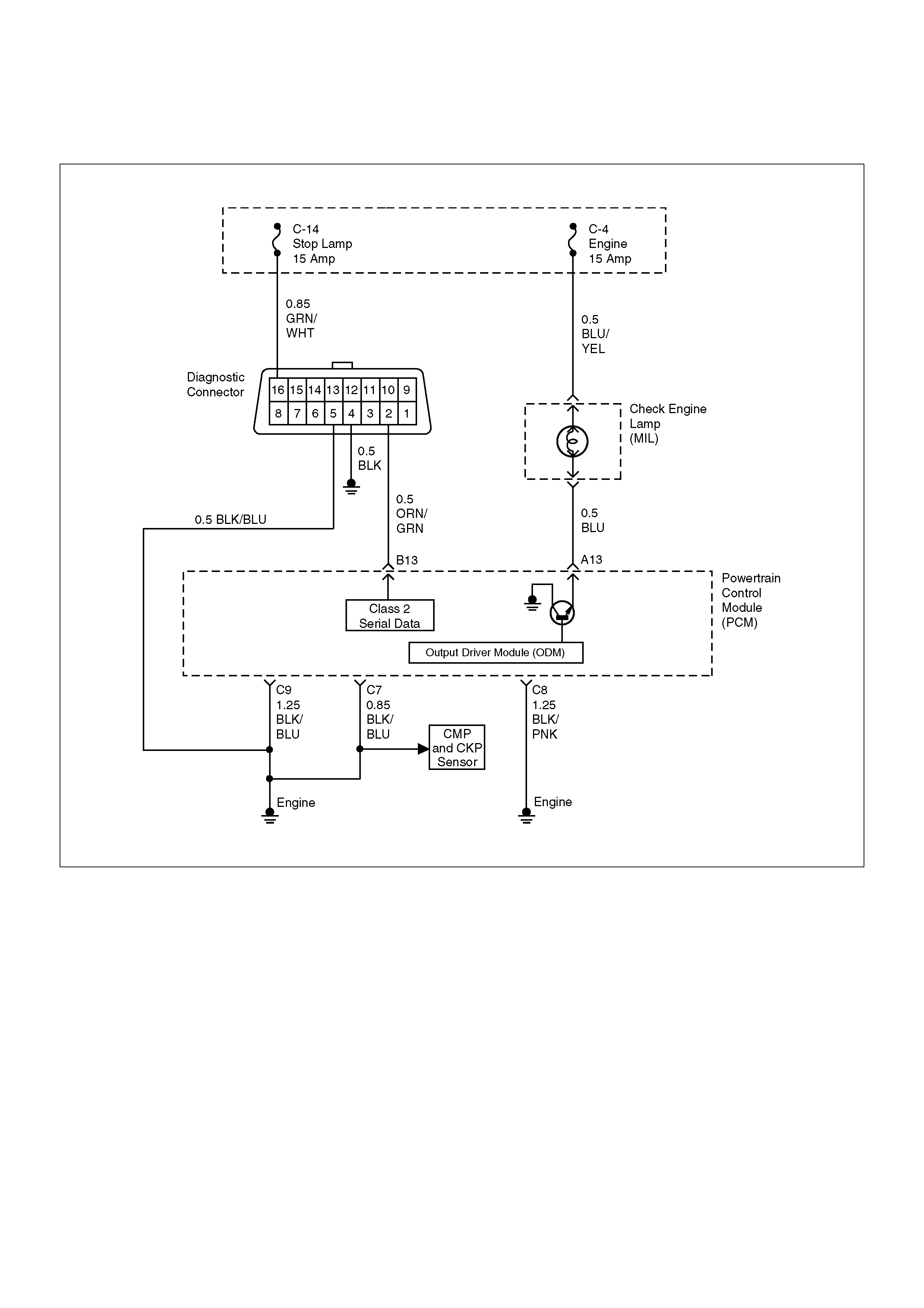
No Malfunction Indicator Lamp (MIL)
D06RW00006
Circuit Description
The “Check Engine” lamp (MIL) should always be
illuminated and steady with the ignition “ON” and the
engine stopped. Ignition feed voltage is supplied to the
MIL bulb through the meter fuse. The powertrain
control module (PCM) turns the MIL “ON” by grounding
the MIL driver circuit.
Diagnostic Aids
An intermittent MIL may be cased by a poor connection,
rubbed-through wire insulation, or a wire broken inside
the insulation. Check for the following items:
•Inspect the PCM harness and connections for
improper mating, broken locks, improperly formed or
damaged terminals, poor terminal-to-wire connection,
and damaged harness.
•If the engine runs OK, check for a faulty light bulb, an
open in the MIL driver circuit, or an open in the
instrument cluster ignition feed.
•If the engine cranks but will not run, check for an
open PCM ignition or battery feed, or a poor PCM to
engine ground.
Test Description
Number(s) below refer to the step number(s) on the
Diagnostic Chart.
2. A “No MIL” condition accompanied by a no-start
condition suggests a faulty PCM ignition feed or
battery feed circuit.
9. Using a test light connected to B+, probe each of the
PCM ground terminals to ensure that a good ground
is present. Refer to PCM Terminal End View for
terminal locations of the PCM ground circuits.
12. In this step, temporarily substitute a known good

relay for the PCM relay. The horn relay is nearby,
and it can be verified as “good” simply by honking
the horn. Replace the horn relay after completing
this step.
Important: 17. This vehicle is equipped with a PCM
which utilizes an electrically erasable programmable
read only memory (EEPROM). When the PCM is
replaced, the new PCM must be programmed. Refer to
Sections OC1 Service Programming System and 11A1
6VE1 Immobiliser.
No Malfunction Indicator Lamp (MIL)
StepActionValue(s)YesNo
1 Was the “On-Board Diagnostic (OBD) System Check”
performed? — Go to Step 2
Go to OBD
System Check
2 Attempt to start the engine.
Does the engine start? — Go to Step 3 Go to Step 6
3 Check the meter fuse for the instrument cluster
ignition feed circuit.
Is the fuse OK? — Go to Step 4 Go to Step 16
4 Ignition “ON,” probe the ignition feed circuit at the
cluster connector with a test light to ground.
Is the test light “ON?” — Go to Step 5 Go to Step 13
5 1. Ignition “OFF.”
2. Disconnect the PCM.
3. Jumper the MIL driver circuit at the PCM
connector to ground.
4. Ignition “ON.”
Is the MIL “ON?” — Go to Step 10 Go to Step 11
6 Check the PCM ignition feed and battery feed fuses
(15 A engine fuse and 15 A PCM fuse).
Are both fuses OK? — Go to Step 7 Go to Step 15
7 1. Ignition “OFF.”
2. Disconnect the PCM.
3. Ignition “ON.”
4. Probe the ignition feed circuit at the PCM harness
connector with a test light to ground.
Is the test light “ON?” — Go to Step 8 Go to Step 12
8 Probe the battery feed circuit at the PCM harness
connector with a test light to ground.
Is the test light “ON?” — Go to Step 9 Go to Step 14
9 Check for a faulty PCM ground connection.
Was a problem found? — Verify repair Go to Step 10
10 Check for damaged terminals at the PCM.
Was a problem found? — Verify repair Go to Step 17
11 Check for an open MIL driver circuit between the PCM
and the MIL.
Was a problem found? — Verify repair Go to Step 18
12 Substitute a known “good” relay for the PCM main
relay.
Was the malfunction fixed? — Verify repair Go to Step 13
13 Repair the open in the ignition feed circuit.
Is the action complete? — Verify repair —
14 Locate and repair the open PCM battery feed circuit.
Is the action complete? — Verify repair —

15 Locate and repair the short to ground in the PCM
ignition feed circuit or PCM battery feed circuit.
Is the action complete?—Verify repair—
16 Locate and repair the short to ground in the ignition
feed circuit to the instrument cluster, and replace the
fuse.
Is the action complete?—Verify repair—
17 Replace the PCM.
Important: The replacement PCM must be
programmed. Refer to Sections OC1 Service
Programming System and 11A1 6VE1 Immobiliser.
Is the action complete?
Important: Is the action complete?—Verify repair—
18 Check the MIL driver circuit for a poor connection at
the instrument panel connector.
Was a problem found?
— Verify repair
Go to
Instrument
Panel in
Electrical
Diagnosis
Step Action Value(s) Yes No
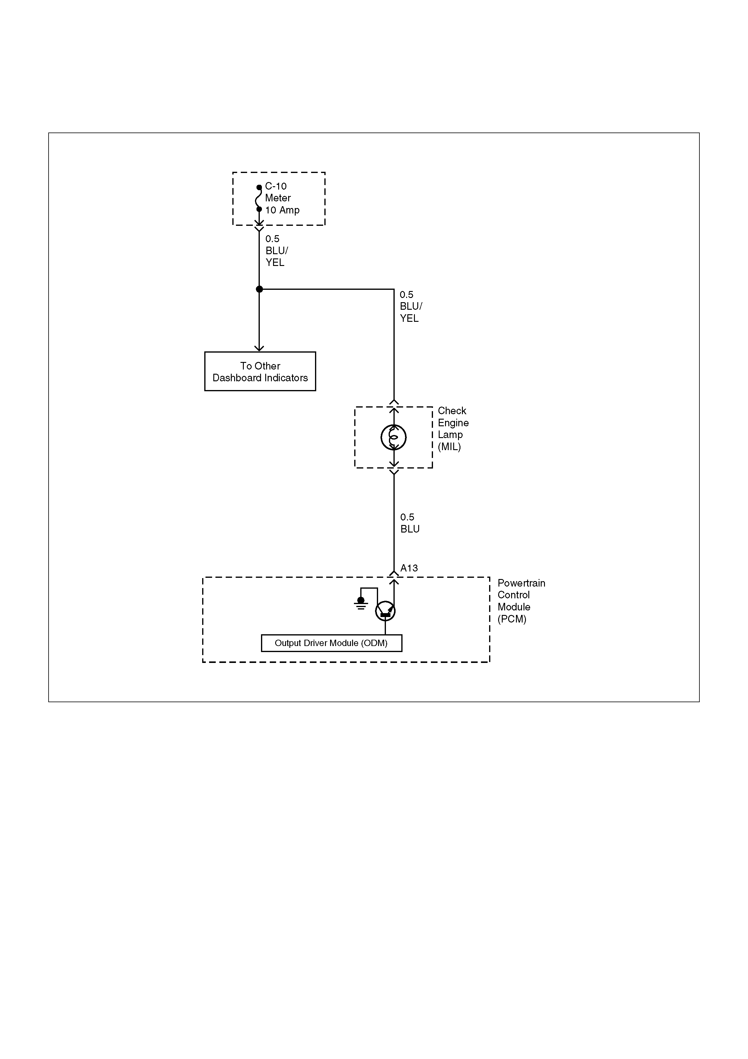
Malfunction Indicator Lamp (MIL) “ON”Steady
D06RW00007
Circuit description
The malfunction indicator lamp (MIL) should always be
illuminated and steady with ignition “ON” and the engine
stopped. Ignition feed voltage is supplied directly to the
MIL indicator. The powertrain control module (PCM)
turns the MIL “ON” by grounding the MIL driver circuit.
The MIL should not remain “ON” with the engine
running and no DTC(s) set. A steady MIL with the
engine running and no DTC(s) suggests a short to
ground in the MIL driver circuit.
Diagnostic Aids
An intermittent may be caused by a poor connection,
rubbed-through wire insulation, or a wire broken inside
the insulation. Check for the following items:
•Poor connection or damaged harness – Inspect the
PCM harness and connectors for improper mating,
broken locks, improperly formed or damaged
terminals, poor terminal-to-wire connection, and
damaged harness.
Test Description
Number(s) below refer to the step number(s) on the
Diagnostic Chart.
2. If the MIL does not remain “ON” when the PCM is
disconnected, the MIL driver wiring is not faulty.
3. If the MIL driver circuit is OK, the instrument panel
cluster is faulty.
Important: 6. This vehicle is equipped with a PCM
which utilizes an electrically erasable programmable
read only memory (EEPROM). When the PCM is
replaced, the new PCM must be programmed.Refer to
Sections OC1 Service Programming System and 11A1
6VE1 Immobiliser.

Malfunction Indicator Lamp (MIL) “ON”Steady
StepActionValue(s)YesNo
1 Was the “On-Board diagnostic (OBD) System Check”
performed?—Go to Step 2
Go to OBD
System Check
2 1.Ignition “OFF,” disconnect PCM.
2.Ignition “ON,” observe the MIL (Service Engine
Soon lamp).
Is the MIL “ON?”—Go to Step 3Go to Step 5
3 1.Ignition “OFF,” disconnect the instrument panel
cluster.
2.Check the MIL driver circuit between the PCM and
the instrument panel cluster for a short to ground.
3.If a problem is found, repair as necessary.
Was the MIL driver circuit shorted to ground?—
Go to OBD
System CheckGo to Step 4
4 Replace the instrument panel cluster.
Is the action complete?—
Go to OBD
System Check—
5 1.Ignition “OFF,” reconnect the PCM.
2.Using Tech 2, select “Output Miscellaneous Test”
and command the MIL “OFF.”
Did the MIL turn “OFF?”—
Go to OBD
System CheckGo to Step 6
6 Replace the PCM.
Important: The replacement PCM must be
programmed. Refer to Sections OC1 Service
Programming System and 11A1 6VE1 Immobiliser.
Is the action complete? —
Go to OBD
System Check —
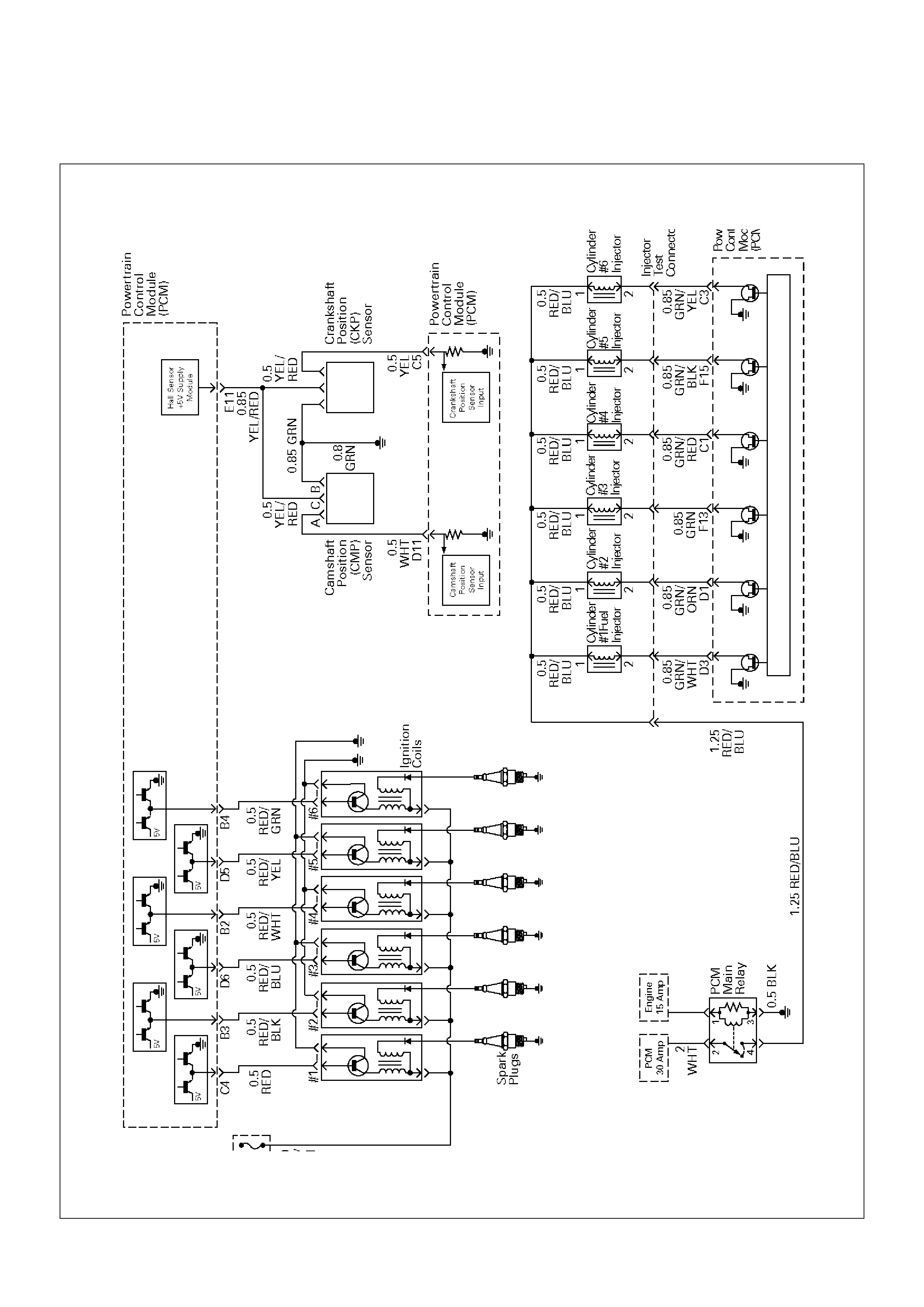
Engine Cranks But Will Not Run
D06RX0 0004

Circuit Description
The electronic Ignition system uses a coil-at-plug
method of spark distribution. In this type of ignition
system, the powertrain control module (PCM) triggers
the correct driver inside the ignition coil, which then
triggers the correct ignition coil based on the 58X signal
received from the crankshaft position sensor (CKP).
The spark plug connected to the coil fires when the ICM
opens the ground circuit for the coil's primary circuit.
During crank, the PCM monitors the CKP 58X signal.
The CKP signal is used to determine which cylinder will
fire first. After the CKP 58X signal has been processed
by the PCM, it will command all six injectors to allow a
priming shot of fuel for all the cylinders. After the
priming, the injectors are left “OFF” during the next six
58X reference pulses from the CKP. This allows each
cylinder a chance to use the fuel from the priming shot.
During this waiting period, a camshaft position (CMP)
signal pulse will have been received by the PCM. The
CMP signal allows the PCM to operate the injectors
sequentially based on camshaft position. If the
camshaft position signal is not present at start-up, the
PCM will begin sequential fuel delivery with a 1-in-6
chance that fuel delivery is correct. The engine will run
without a CMP signal, but will set a DTC code.
Diagnostic Aids
An intermittent problem may be caused by a poor
connection, rubbed-through wire insulation or a wire
broken inside the insulation. Check for the following
items:
•Poor connection or damaged harness – Inspect the
PCM harness and connectors for improper mating,
broken locks, improperly formed or damaged
terminals, poor terminal-to-wire connection, and
damaged harness.
•Faulty engine coolant temperature sensor – Using
Tech 2, compare engine coolant temperature with
intake air temperature on a completely cool engine.
Engine coolant temperature should be within 10°C of
intake air temperature. If not, replace the ECT
sensor.
Test Description
Number(s) below refer to the step number(s) on the
Diagnostic Chart.
5. An obvious cause of low fuel pressure would be an
empty fuel tank.
6. The engine will easily start and run if a few injectors
are disabled. It is not necessary to test all injectors
at this time since this step is only a test to verify that
all of the injectors have not been disabled by fuel
contamination.
7. A blinking test light verifies that the PCM is
monitoring the 58X crankshaft reference signal and
is capable of activating the injectors. If there is an
open or shorted driver circuit, DTCs 201-206 should
be set.
19. By using a spark tester, each ignition coil's ability to
produce 25,000 volts is verified.
25. If there is an open or shorted driver circuit, DTCs
201-206 should be set. All six injector driver circuits
can be checked at one time without removing the
intake manifold if a 5-8840-2636-0 test light is
available. This is the alternative procedure:
•With the ignition “OFF,” disconnect the gray
connector located at the rear of the air filter,
attached to a bracket on the purge canister.
•Connect test light 5-8840-2636-0 to the connector.
Do any of the light constantly illuminate or fail to
blink when the engine is cranked? If so, repair the
short or open circuit, or replace the PCM if
indicated.
This procedure only tests the driver circuit as far as the
test connection, so step 31 is added to test the circuit all
the way to the injector.
Engine Cranks But Will Not Run
StepActionValue(s)YesNo
1 Was the “On-Board Diagnostic (OBD) System Check”
performed? — Go to Step 2
Go to OBD
System Check
2 Check the 15 A (C9) ignition coil fuse, the 15 A (C8)
engine fuse, and the 30 A (F13) PCM fuse.
Was a fuse blown? — Go to Step 3 Go to Step 4
3 Check for a short to ground and replace the fuse.
Is the action complete? — Verify repair —
4 1. Ignition “OFF,” install a fuel pressure gauge at the
test fitting on the fuel supply line in the engine
compartment. (Use a shop cloth to absorb any
fuel leakage while making the connection.)
2. Ignition “ON,” observe the fuel pressure.
Is the fuel pressure within the specified values, and
does it hold steady?
285-376kPa
(43-55psi) Go to Step 6 Go to Step 5

5 Is any fuel pressure indicated?
—
Go to Fuel
System
Electrical Test
Go to Fuel
System
Diagnosis
6 Install an injector switch box to the injector test
connector, and attempt to operate the injector.
Did the fuel pressure drop when the injector is
operated? — Go to Step 7 Go to Step 12
7 Install an injector test light at the #2 cylinder injector
harness connector.
Does the light blink when the engine is cranked? — Go to Step 8 Go to Step 18
8 1. Ignition “ON.”
2. With the ignition coil connectors disconnected,
touch each coil connector's ignition feed terminal
with a grounded test light (the ignition feed wire is
black with orange tracer).
Did the test light illuminate? — Go to Step 10 Go to Step 9
9 Repair the open ignition feed circuit.
Is the action complete? — Verify repair —
10 While the coil connectors are disconnected, touch
each connector's secondary ground terminal with a
test light to B+. (The ground wires are black.)
Did the test light illuminate at each coil connector? — Go to Step 12 Go to Step 11
11 Repair the open secondary ground circuit.
Is the action complete? — Verify repair —
12 1. Test the fuel for contamination.
2. If a problem is found, clean the fuel system and
correct the contaminated fuel condition as
necessary. Replace the fuel filter and replace any
injectors that are not delivering fuel (see Injector
Balance Test).
Was a problem found? — Verify repair Go to Step 13
13 1. Remove any ignition coil and install a spark tester
at the spark plug end of the coil.
2. Observe the tester while the engine is cranking.
Was a crisp, blue spark observed? Only one or two
sparks followed by no result is considered the same
as “No Spark.” — Go to Step 15 Go to Step 14
14 Replace the ignition coil, and return to Step 13 to test
the remaining coils.
Is the action complete? — Verify repair —
15 Repeat Step 13 for each coil. Remove only one coil at
a time, and reinstall each coil on its spark plug after
testing, but do not refasten coils with screws at this
time.
After all coils have passed the spark test, does the
engine start? —
Refasten all
coils with their
screws Go to Step 16
16 1. Remove the spark plugs from all cylinders.
2. Visually inspect the spark plug electrodes.
3. Replace any spark plugs with loose or missing
electrodes or cracked insulators.
Did your inspection reveal any spark plugs exhibiting
excessive fouling? —
Correct the
fouling
condition Go to Step 17
Step Action Value(s) Yes No

17 Refer to Engine Mechanical Diagnosis to diagnose the
following conditions:
• Faulty or incorrect camshaft drive belts
• Leaking or sticky valves or rings
• Excessive valve deposits
• Loose or worn rocker arms
• Weak valve springs
• Incorrect valve timing
• Leaking head gasket
Is the action complete? — Verify repair Go to Step 19
18 Observe the “Engine Speed” data display on the scan
tool while cranking the engine.
Is the engine RPM indicated? (If the scan tool is
normally powered from the cigarette lighter socket,
and if the scan tool display goes blank while cranking
the engine, it will be necessary to power the scan tool
directly from the vehicle battery.) — Go to Step 19 Go to Step 28
19 1. Disconnect the 7-pin gray connector at the rear of
the air filter beneath the point where the air duct
attaches to the MAF sensor.
2. Ignition “ON.”
3. Using a test light connected to ground, probe the
ignition terminal at the PCM (female) side of the
7-pin connector.
Is the test light “ON?” — Go to Step 20 Go to Step 26
20 1. At the PCM (female) side of the connector,
connect a test light between the ignition + terminal
and one of the injector driver circuits at the same
connector.
2. Ignition “ON.”
3. Observe the test light, and repeat the test for each
injector driver circuit.
Did the test light stay on when checking any of the 6
injector driver circuits? — Go to Step 21 Go to Step 23
21 1. Ignition “OFF,” disconnect the PCM.
2. Ignition “ON,” observe the test light.
Is the test light “ON?” — Go to Step 22 Go to Step 27
22 Locate and repair the short to ground in the injector
driver circuit.
Is the action complete? — Verify repair —
23 1. Using the same test location as in step 20,
connect a test light between the ignition terminal
and one of the driver circuits.
2. Crank the engine and observe the test light.
3. Repeat for each injector driver circuit.
Did the light blink during the test for each circuit? — Go to Step 25 Go to Step 24
24 Check for an open injector driver circuit.
Was a problem found? — Verify repair Go to Step 27
Step Action Value(s) Yes No

25 1.At the injector (male) side of the gray connector,
connect an ohmmeter between the ignition pin
and one of the driver circuit pins.
2.Check for continuity in the circuit.
3.Repeat for each injector circuit. The readings
should be approximately equal to the specified
value for injector resistance.
Was a problem found?12.5 ohmsVerify repairGo to Step 8
26 Repair the ignition feed circuit.
Is the action complete?—Verify repair—
27 Replace the PCM.
Important: The replacement PCM must be
programmed. Refer to Sections OC1 Service
Programming System and 11A1 6VE1 Immobiliser.
Is the action complete? — Verify repair —
28 1. Raise the vehicle and disconnect the CKP sensor
harness.
2. Ignition “ON.”
3. With a test light to ground, probe the harness
ignition feed terminal.
Did the light illuminate? — Go to Step 30 Go to Step 29
29 Check the ignition feed wire between the sensor and
the PCM for a short to ground or open circuit.
Is the action complete? — Verify repair —
30 1. Ignition “ON.”
2. At the CKP harness connector, connect a test light
between the ignition and ground terminals.
Did the light illuminate? — Go to Step 32 Go to Step 31
31 Check the sensor ground circuit for an open or short
to voltage.
Is the action complete? — Verify repair —
32 Check the signal circuit between the sensor and the
PCM for a short to ground, short to voltage, or an
open.
Was a problem found? — Verify repair Go to Step 33
33 Replace the CKP sensor.
Is the action complete? — Verify repair Go to Step 27
Step Action Value(s) Yes No
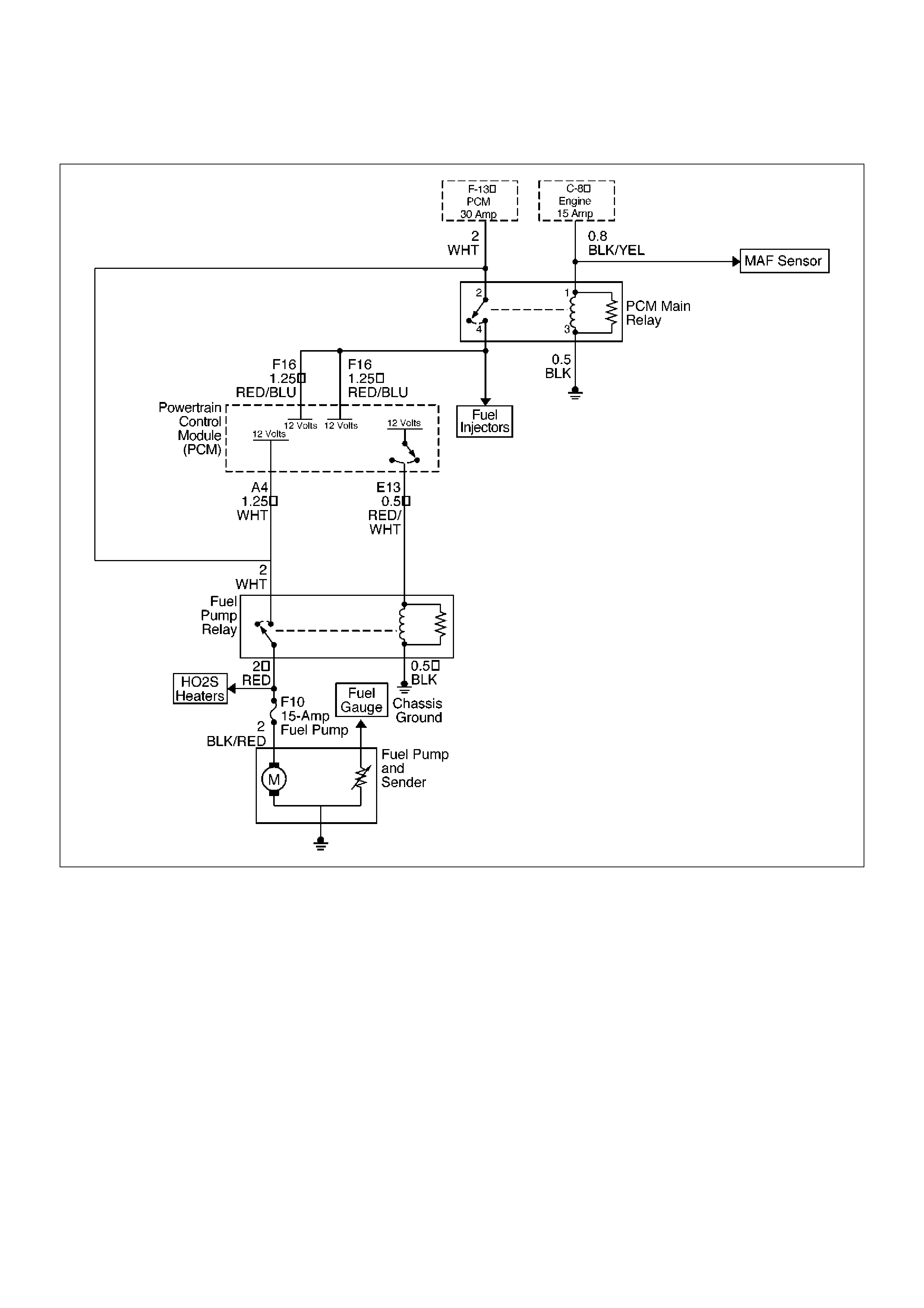
Fuel System Electrical Test
D06RW101
Circuit Description
When the ignition switch is first turned “ON,” the
powertrain control module (PCM) energizes the fuel
pump relay which applies power to the in-tank fuel
pump. The fuel pump relay will remain “ON” as long as
the engine is running or cranking and the PCM is
receiving 58X crankshaft position pulses. If no 58X
crankshaft position pulses are present, the PCM
de-energizes the fuel pump relay within 2 seconds after
the ignition is turned “ON” or the engine is stopped.
The fuel pump delivers fuel to the fuel rail and injectors,
then to the fuel pressure regulator. The fuel pressure
regulator controls fuel pressure by allowing excess fuel
to be returned to the fuel tank. With the engine stopped
and ignition “ON,” the fuel pump can be turned “ON” by
using a command by Tech 2.
Diagnostic Aids
An intermittent may be caused by a poor connection,
rubbed-through wire insulation, or a wire broken inside
the insulation. Check for the following items:
• Poor connection or damaged harness – Inspect the
PCM harness and connectors for improper mating,
broken locks, improperly formed or damaged
terminals, poor terminal-to-wire connection, and
damaged harness.
Test Description
Number(s) below refer to the step number(s) on the
Diagnostic Chart.
2. If the fuel pump is operating but incorrect pressure is
noted, the fuel pump wiring is OK and the “Fuel
System Pressure Test” chart should be used for
diagnosis.

CAUTION: To reduce the risk of fire and personal
injury:
•It is necessary to relieve fuel system pressure
before connecting a fuel pressure gauge. Refer
to Fuel Pressure Relief Procedure, below.
•A small amount of fuel may be released when
disconnecting the fuel lines. Cover fuel line
fittings with a shop towel before disconnecting,
to catch any fuel that may leak out. Place the
towel in an approved container when the
disconnect is completed.
Fuel Pressure Relief Procedure
1.Remove the fuel cap.
2.Remove the fuel pump relay from the underhood
relay center.
3.Start the engine and allow it to stall.
4.Crank the engine for an additional 3 seconds.
Fuel Gauge Installation
1.Remove the shoulder fitting cap.
2.Install fuel gauge 5-8840-0378-0 to the fuel feed line
located in front of and above the right side valve
train cover .
3.Reinstall the fuel pump relay.
Fuel System Electrical Test
StepActionValue(s)YesNo
1 Was the “On-Board Diagnostic (OBD) System Check”
performed? — Go to Step 2
Go to OBD
System Check
2 1. Read the “Caution” above.
2. Relieve the fuel system pressure and install the
fuel pump pressure gauge to the test fitting.
3. Use Tech 2 to command the fuel pump “ON.”
Is there an immediate pressure build-up which
indicates the pump is running? — Go to Step 3 Go to Step 4
3 1. Verify that the pump is not running by removing
the fuel filler cap and listening.
2. Command the pump “ON” with Tech 2.
Did the pump turn “OFF” after 2 seconds? — Test completed Go to Step 12
4 1. Ignition “OFF.”
2. Remove the fuel pump relay.
3. Using a test light connected to ground, probe the
battery feed to the relay.
Did the light illuminate? — Go to Step 6 Go to Step 5
5 Repair short or open battery feed to fuel pump relay.
Is the action complete? — Verify repair —
6 1. Connect a test light between the two wires that
connect to the fuel pump relay pull-in coil.
2. Ignition “ON.”
Did the test light illuminate for 2 seconds and then turn
off? — Go to Step 12 Go to Step 7
7 1. With a test light connected to battery (–), probe
the fuel pump relay connector at the wire which
runs from the relay pull-in coil to the PCM.
2. Ignition “ON.”
Did the test light illuminate for 2 seconds and then turn
off? — Go to Step 8 Go to Step 9
8 Locate and repair open in the fuel pump relay ground
circuit.
Is the action complete? — Verify repair —
9 Check for short or open between the PCM and the
fuel pump relay.
Was a problem found? — Verify repair Go to Step 10

10 1.Check the fuel pump relay circuit for a poor
terminal connection at the PCM.
2.If a problem is found, replace terminal as
necessary.
Was a problem found?—Verify repairGo to Step 11
11 Replace the PCM.
Important: The replacement PCM must be
programmed. Refer to Sections OC1 Service
Programming System and 11A1 6VE1 Immobiliser.
Is the action complete? — Verify repair —
12 1. Reconnect the fuel pump relay.
2. Disconnect the fuel pump electrical connector at
the fuel tank.
3. Using a test light connected to ground, probe the
fuel pump feed wire (harness side).
4. Command the fuel pump “ON” with Tech 2.
Did the light illuminate for 2 seconds? — Go to Step 15 Go to Step 13
13 1. Honk the horn to verify that the horn relay is
functioning.
2. Substitute the horn relay for the fuel pump relay.
3. Leave the test light connected as in step 12.
4. Command the fuel pump “ON” with Tech 2.
Did the test light illuminate for 2 seconds when the
fuel pump was commanded “ON?” — Go to Step 17 Go to Step 14
14 1. Re-connect the horn relay in its proper location.
2. Check for a short circuit, blown fuse or open circuit
between the relay and the fuel tank.
Is the action complete? — Verify repair —
15 1. With the fuel pump electrical connector at the fuel
tank disconnected, connect a test light between
the feed wire and the ground wire (harness side).
2. Command the fuel pump “ON” with Tech 2.
Did the test light illuminate for 2 seconds? — Go to Step 18 Go to Step 16
16 Repair the open circuit in the fuel pump ground wire.
Is the action complete? — Verify repair —
17 1. Re-connect the horn relay in its proper location.
2. Replace the fuel pump relay.
Is the action complete? — Verify repair —
18 Replace the fuel pump.
Is the action complete? — Verify repair —
Step Action Value(s) Yes No
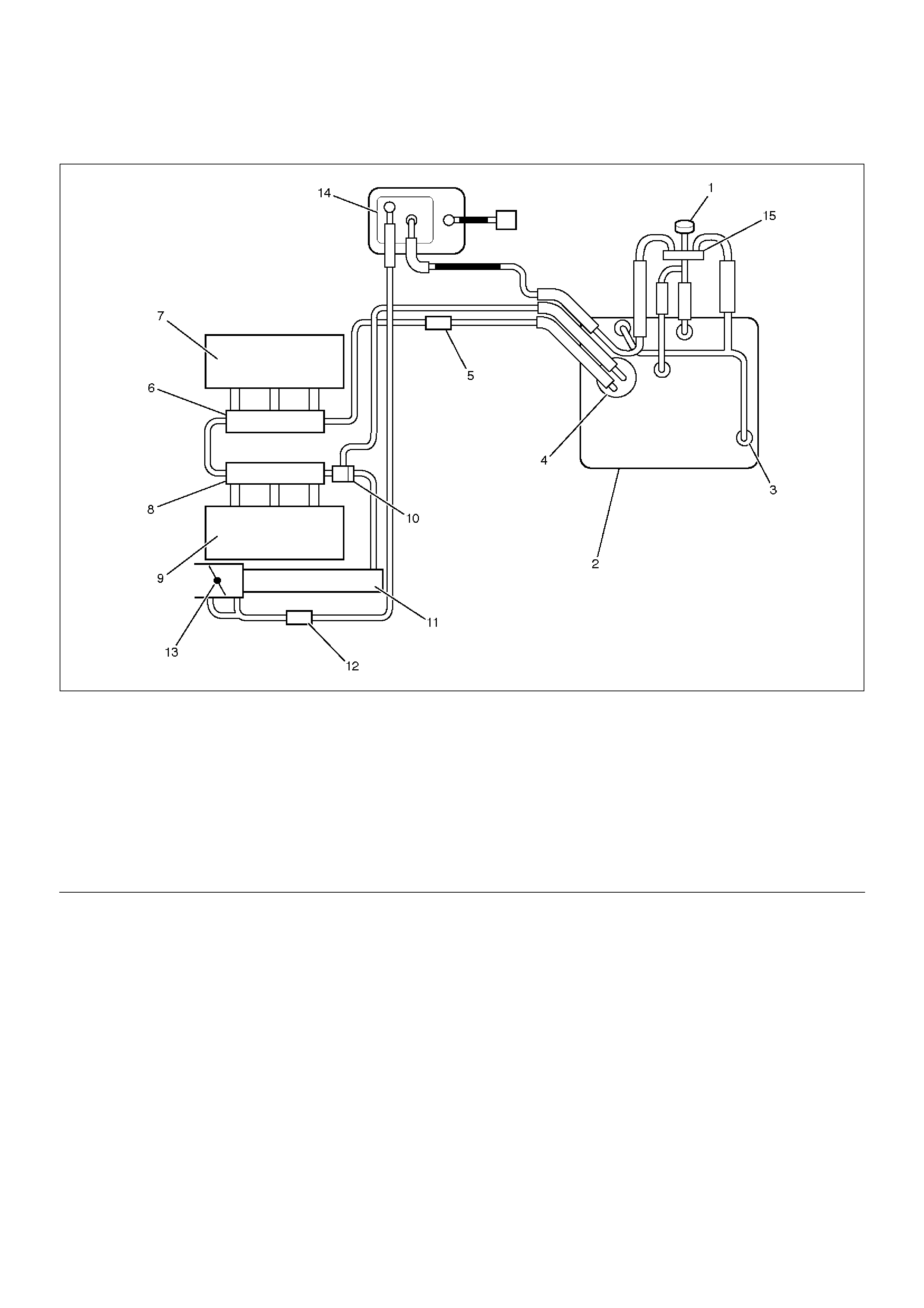
Fuel System Diagnosis
140RW020
EndOFCallout
Circuit Description
When the ignition switch is turned “ON,” the powertrain
control module (PCM) will turn “ON” the in-tank fuel
pump. The in-tank fuel pump will remain “ON” as long
as the engine is cranking or running and the PCM is
receiving 58X crankshaft position pulses. If there are no
58X crankshaft position pulses, the PCM will turn the
in-tank fuel pump “OFF” 2 seconds after the ignition
switch is turned “ON” or 2 seconds after the engine
stops running.
The in-tank fuel pump is an electric pump within an
integral reservoir. The in-tank fuel pump supplies fuel
through an in-line fuel filter to the fuel rail assembly.
The fuel pump is designed to provide fuel at a pressure
above the pressure needed by the fuel injectors. A fuel
pressure regulator, attached to the fuel rail, keeps the
fuel available to the fuel injectors at a regulated
pressure. Unused fuel is returned to the fuel tank by a
separate fuel return line.
Test Description
Number(s) below refer to the step number(s) on the
Diagnostic Chart.
2. Connect the fuel pressure gauge to the fuel feed line
as shown in the fuel system illustration. Wrap a
shop towel around the fuel pressure connection in
order to absorb any fuel leakage that may occur
when installing the fuel pressure gauge. With the
ignition switch “ON” and the fuel pump running, the
fuel pressure indicated by the fuel pressure gauge
should be 333-376kPa (48-55psi). This pressure is
controlled by the amount of pressure the spring
inside the fuel pressure regulator can provide.
3. A fuel system that cannot maintain a constant fuel
Legend
(1) Fuel Filler Cap
(2) Fuel Tank
(3) Rollover Valve
(4) Fuel Pump and Sender Assembly
(5) Fuel Filter
(6) Fuel Rail Right
(7) Right Bank
(8) Fuel Rail Left
(9) Left Bank
(10) Fuel Pressure Control Valve
(11) Common Chamber
(12) Duty Solenoid Valve
(13) Throttle Valve
(14) Canister
(15) Evapo Shut Off Valve

pressure has a leak in one or more of the following
areas:
•The fuel pump check valve.
•The fuel pump flex line.
•The valve or valve seat within the fuel pressure
regulator.
•The fuel injector(s).
4. Fuel pressure that drops off during acceleration,
cruise, or hard cornering may case a lean condition.
A lean condition can cause a loss of power, surging,
or misfire. A lean condition can be diagnosed using
a Tech II Tech 2. If an extremely lean condition
occurs, the oxygen sensor(s) will stop toggling. The
oxygen sensor output voltage(s) will drop below 500
mV. Also, the fuel injector pulse width will increase.
Important: Make sure the fuel system is not operating
in the “Fuel Cut-Off Mode.”
When the engine is at idle, the manifold pressure is
low (high vacuum). This low pressure (high vacuum)
is applied to the fuel pressure regulator diaphragm.
The low pressure (high vacuum) will offset the
pressure being applied to the fuel pressure regulator
diaphragm by the spring inside the fuel pressure
regulator. When this happens, the result is lower
fuel pressure. The fuel pressure at idle will vary
slightly as the barometric pressure changes, but the
fuel pressure at idle should always be less than the
fuel pressure noted in step 2 with the engine “OFF.”
16. Check the spark plug associated with a particular
fuel injector for fouling or saturation in order to
determine if that particular fuel injector is leaking. If
checking the spark plug associated with a particular
fuel injector for fouling or saturation does not
determine that a particular fuel injector is leaking,
use the following procedure:
•Remove the fuel rail, but leave the fuel lines and
injectors connected to the fuel rail. Refer to Fuel
Rail Assembly in On-Vehicle Service.
•Lift the fuel rail just enough to leave the fuel
injector nozzles in the fuel injector ports.
CAUTION: In order to reduce the risk of fire and
personal injury that may result from fuel spraying
on the engine, verify that the fuel rail is positioned
over the fuel injector ports and verify that the fuel
injector retaining clips are intact.
•Pressurize the fuel system by connecting a 10
amp fused jumper between B+ and the fuel pump
relay connector.
•Visually and physically inspect the fuel injector
nozzles for leaks.
17. A rich condition may result from the fuel pressure
being above 376kPa (55psi). A rich condition may
cause a DTC P0132 or a DTC P0172 to set.
Driveability conditions associated with rich
conditions can include hard starting (followed by
black smoke) and a strong sulfur smell in the
exhaust.
20. This test determines if the high fuel pressure is due
to a restricted fuel return line or if the high fuel
pressure is due to a faulty fuel pressure regulator.
21. A lean condition may result from fuel pressure below
333kPa (48psi). A lean condition may cause a DTC
P0131 or a DTC P0171 to set. Driveability
conditions associated with lean conditions can
include hard starting (when the engine is cold ),
hesitation, poor driveability, lack of power, surging ,
and misfiring.
22. Restricting the fuel return line causes the fuel
pressure to rise above the regulated fuel pressure.
Command the fuel pump “ON” with Tech 2. The fuel
pressure should rise above 376kPa (55psi) as the
fuel return line becomes partially closed.
NOTE: Do not allow the fuel pressure to exceed
414kPa (60psi). Fuel pressure in excess of 414kPa
(60psi) may damage the fuel pressure regulator.
CAUTION: To reduce the risk of fire and personal
injury:
•It is necessary to relieve fuel system pressure
before connecting a fuel pressure gauge. Refer
to Fuel Pressure Relief Procedure, below.
• A small amount of fuel may be released when
disconnecting the fuel lines. Cover fuel line
fittings with a shop towel before disconnecting,
to catch any fuel that may leak out. Place the
towel in an approved container when the
disconnect is completed.
Fuel Pressure Relief Procedure
1. Remove the fuel cap.
2. Remove the fuel pump relay from the underhood
relay center.
3. Start the engine and allow it to stall.
4. Crank the engine for an additional 3 seconds.
Fuel Gauge Installation
1. Remove the shoulder fitting cap.
2. Install fuel gauge 5-8840-0378-0 to the fuel feed line
located in front of and above the right side valve
train cover.
3. Reinstall the fuel pump relay.

Fuel System Diagnosis
StepActionValue(s)YesNo
1 Was the “On-Board Diagnostic (OBD) System Check”
performed? — Go to Step 2
Go to OBD
System Check
2 1. Turn the ignition “OFF.”
2. Turn the air conditioning system “OFF.”
3. Relieve fuel system pressure and install the fuel
pressure gauge.
4. Turn the ignition “ON.”
NOTE: The fuel pump will run for approximately 2
seconds. Use Tech 2 to command the fuel pump“ON”.
5. Observe the fuel pressure indicated by the fuel
pressure gauge with the fuel pump running.
Is the fuel pressure within the specified limits?
290-376kPa
(42-55psi) Go to Step 3 Go to Step 17
3 NOTE: The fuel pressure will drop when the fuel
pump stops running, then it should stabilize and
remain constant.
Does the fuel pressure indicated by the fuel pressure
gauge remain constant? — Go to Step 4 Go to Step 12
4 1. When the vehicle is at normal operation
temperature, turn the ignition “ON” to build fuel
pressure and observe the measurement on the
gauge.
2. Start the engine and observe the fuel pressure
gauge.
Did the reading drop by the amount specified after the
engine was started?
21-105kPa
(3-15psi) Go to Step 5 Go to Step 9
5 Is fuel pressure dropping off during acceleration,
cruise, or hard cornering? — Go to Step 6
Check for
improper fuel
6 Visually and physically inspect the following items for
a restriction:
• The fuel filter.
• The fuel feed line.
Was a restriction found? — Verify repair Go to Step 7
7 Remove the fuel tank and visually and physically
inspect the following items:
• The fuel pump strainer for a restriction.
• The fuel line for a leak.
• Verify that the correct fuel pump is in the vehicle.
Was a problem found in any of these areas? — Verify repair Go to Step 8
8 Replace the fuel pump.
Is the action complete? — Verify repair —
9 1. Disconnect the vacuum hose from the fuel
pressure regulator.
2. With the engine idling, apply 12-14 inches of
vacuum to the fuel pressure regulator.
Does the fuel pressure indicated by the fuel pressure
gauge drop by the amount specified?
21-105kPa
(3-15psi) Go to Step 10 Go to Step 11
10 Locate and repair the loss of vacuum to the fuel
pressure regulator.
Is the action complete? — Verify repair —

11 Replace the fuel pressure regulator.
Is the action complete? — Verify repair —
12 1. Run the fuel pump with Tech 2.
2. After pressure has built up, turn off the pump and
clamp the supply hose shut with suitable locking
pliers.
Does the fuel pressure indicated by the fuel pressure
gauge remain constant? — Go to Step 13 Go to Step 15
13 Visually inspect the fuel supply line and repair any
leaks.
Was a problem found? — Verify repair Go to Step 14
14 Remove the fuel tank and inspect for leaky hose or
in-tank fuel line.
Was a problem found? — Verify repair Go to Step 8
15 1. If the pliers are still clamped to the fuel supply
hose, remove the locking pliers.
2. With suitable locking pliers, clamp the fuel return
line to prevent fuel from returning to the fuel tank.
3. Run the fuel pump with Tech 2.
4. After pressure has built up, remove power to the
pump.
Does the fuel pressure indicated by the fuel pressure
gauge remain constant? — Go to Step 11 Go to Step 16
16 Locate and replace any leaking fuel injector(s).
Is the action complete? — Verify repair —
17 Is the fuel pressure indicated by the fuel pressure
gauge above the specified limit?
376kPa
(55psi) Go to Step 18 Go to Step 21
18 1. Relieve the fuel pressure. Refer to the Fuel
Pressure Relief.
2. Disconnect the fuel return line from the fuel rail.
3. Attach a length of flexible hose to the fuel rail
return outlet passage.
4. Place the open end of the flexible hose into an
approved gasoline container.
5. Run the fuel pump with Tech 2.
6. Observe the fuel pressure indicated by the fuel
pressure gauge with the fuel pump running.
Is the fuel pressure within the specified limits?
290-376kPa
(42-55psi) Go to Step 19 Go to Step 20
19 Locate and correct the restriction in the fuel return
line.
Is the action complete? — Verify repair —
20 Visually and physically inspect the fuel rail outlet
passages for a restriction.
Was a restriction found? — Verify repair Go to Step 11
21 Is the fuel pressure indicated by the fuel pressure
gauge above the specified value? 0kPa (0psi) Go to Step 22 Go to Step 23
Step Action Value(s) Yes No

22 1.Command the fuel pump “ON” with Tech 2.
2.Using suitable pliers which will not damage the
fuel hose, gradually apply pressure with the pliers
to pinch the flexible fuel return hose closed.
CAUTION: Do not let the fuel pressure exceed the
second specified value.
Does the fuel pressure indicated by the fuel pressure
gauge rise above the first specified value?
376kPa
(55psi)
414kPa
(60psi) Go to Step 11 Go to Step 7
23 1. Command the fuel pump “ON” with Tech 2.
2. Remove the fuel filler cap and listen for the sound
of the fuel pump running.
3. Turn the pump off.
Was the fuel pump running? — Go to Step 7
Go to Fuel
System
Electrical Test
Chart
Step Action Value(s) Yes No

Idle Air Control (IAC) System Check
Circuit Description
The powertrain control module (PCM) controls engine
idle speed with the idle air control (IAC) valve. To
increase idle speed, the PCM retracts the IAC valve
pintle away from its seat, allowing more air to bypass
the throttle bore. To decrease idle speed, it extends the
IAC valve pintle towards its seat, reducing by pass air
flow. Tech 2 will read the PCM commands to the IAC
valve in counts. Higher counts indicate more air bypass
(higher idle). Lower counts indicate less air is allowed
to bypass (lower idle).
Diagnostic Aids
A slow, unstable, or fast idle may be caused by a
non-IAC system problem that cannot be overcome by
the IAC valve. Out of control range IAC Tech 2 counts
will be above 60 if idle is too low, and zero counts if idle
is too high. The following checks should be made to
repair a non-IAC system problem:
•Vacuum leak (high idle) – If idle is too high, stop the
engine. Fully extend (low) IAC with the Tech 2. Start
the engine. If idle speed is above 800 RPM, locate
and correct the vacuum leak, including the PCV
system. Check for binding of the throttle blade or
linkage.
•Lean heated oxygen sensor signal (high air/fuel ratio)
– The idle speed may be too high or too low. Engine
speed may vary up and down, and disconnecting the
IAC valve does not help. Diagnostic trouble codes
P0131, P0151, P0171, or P0174 may be set. Tech 2
oxygen (O2) voltage will be less than 100 mV (0.1 V).
Check for low regulated fuel pressure, water in fuel,
or a restricted injector.
•Rich heated oxygen sensor signal (low air/fuel ratio)
– The idle speed will be too low. Tech 2 IAC counts
will usually be above 80. The system is obviously
rich and may exhibit black smoke in the exhaust.
Tech 2 O2 voltage will be fixed at about 750 mV (0.75
V). Check for high fuel pressure, or a leaking or
sticking injector. A silicon-contaminated heated
oxygen sensor will show an O2 voltage slow to
respond on Tech 2.
•Throttle body – Remove the IAC valve and inspect
the bore for foreign material.
•IAC valve electrical connections – IAC valve
connections should be carefully checked for proper
contact.
•PCV valve – An incorrect or faulty PCV valve may
result in an incorrect idle speed. Refer to Diagnosis,
Rough Idle, Stalling. If intermittent poor driveability or
idle symptoms are resolved by disconnecting the
IAC, carefully recheck the connections and valve
terminal resistance, or replace the IAC.
Test Description
Number(s) below refer to the step number(s) on the
Diagnostic Chart.
1. The Tech 2 is used to extend and retract the IAC
valve. Valve movement is verified by an engine
speed change. If no change in engine speed occurs,
the valve can be resettled when removed from the
throttle body.
2. This step checks the quality of the IAC movement in
step 1. Between 700 revolutions per minute (RPM)
and about 1500 RPM, the engine speed should
change smoothly with each flash of the tester light in
both extend and retract. If the IAC valve is retracted
beyond the control range (about 1500 RPM), it may
take many flashes to extend the IAC valve before
engine speed will begin to drop. This is normal on
certain engines. Fully extending the IAC may cause
engine stall. This may be normal.

Idle Air Control (IAC) System Check
Step Action Value(s) Yes No
1 1. Ignition “OFF.”
2. Connect the Tech 2.
3. Set the parking brake.
4. Block the wheels.
5. Turn the air conditioning “OFF.”
6. Idle the engine in Park (A/T) or Neutral (M/T).
7. Operate the IAC test.
8. The engine speed should decrease and increase
as the IAC is cycled.
Does the RPM change? — Go to Step 2 Go to Step 3
2 RPM should change smoothly.
Does the RPM change within the range specified?
700-1500
RPM — Go to Step 3
3 Check the IAC passages.
Are the IAC passages OK? — Go to Step 4 Go to Step 5
4 Clear any obstruction from the IAC passages.
Is the action complete? — Verify repair —
5 Replace the IAC. Refer to On-Vehicle Service, Idle
Air Control Valve.
Is the action complete? — Verify repair —
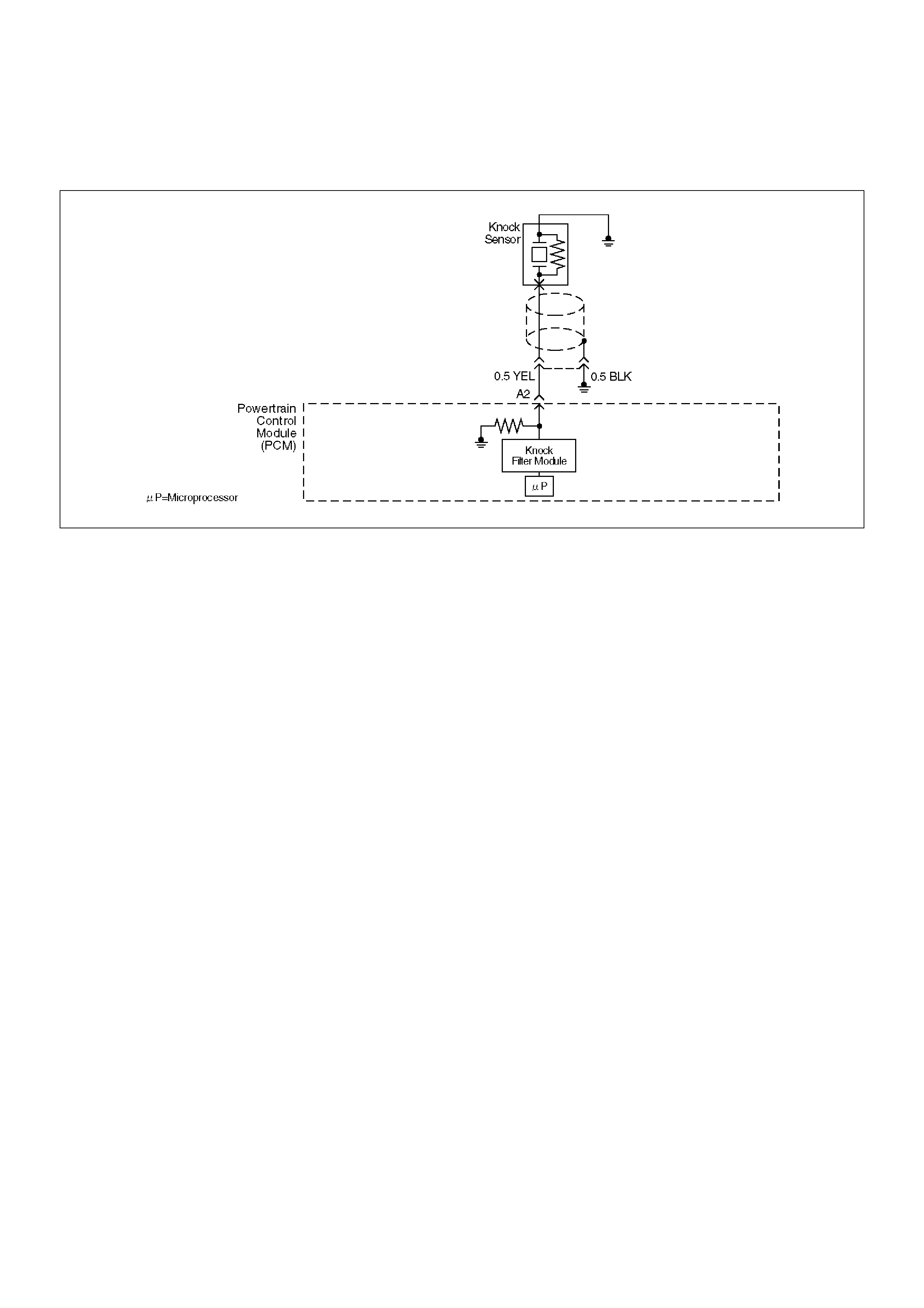
Knock Sensor (KS) System Check (Engine Knock, Poor Performance, or Poor
Economy)
D06RW035
Circuit Description
The knock sensor (KS) sends an AC voltage signal to
the powertrain control module (PCM). As the KS
detects engine knock, the signal to the PCM changes in
amplitude and frequency. The PCM retards timing if the
engine speed is over 900 RPM.
Diagnostic Aids
If the KS system checks OK, but detonation is the
complaint, refer to Diagnosis, Detonation/Spark Knock.
Test Description
The numbers below refer to the step numbers on the
Diagnostic Chart.
9. The change in signal speed depends on how hard
the tapping is done. Normally there is about 1.5 to
10 mV at PCM pin A2 with the engine off. Loud
tapping should be able to make the reading jump to
20-25 mV AC.

Knock Sensor (KS) System Check (Engine Knock, Poor Performance, or Poor
Economy)
StepActionValue(s)YesNo
1 Is DTC P0325 or P0327 set?
—
Go to DTC
P0325 or DTC
P0327Go to Step 2
2 Run the engine at 1500 RPM.
Is there an internal engine knock?—Go to Step 3Go to Step 4
3 Repair the mechanical problem.
Is the action complete?—Verify repair—
4 1.Install Tech 2.
2.Turn the ignition “ON.”
3.Cycle through the list until “Knock Retard” is
displayed.
Is knock retard at the specified value?0°Go to Step 6Go to Step 7
5 Replace the PCM.
Important: The replacement PCM must be
programmed. Refer to Sections OC1 Service
Programming System and 11A1 6VE1 Immobiliser.
Important: Is the action complete?—Verify repair—
6 1. Start the engine.
2. Monitor the knock retard display on Tech 2 while
changing the throttle setting to place different
loads on the engine.
Is knock retard at the specified value? (Turn the
ignition“OFF.”) 0°Go to Step 9 Go to Step 7
7 1. At the rear of the engine, behind the rear fuel
injector on the lift side, disconnect the 2-wire
knock sensor harness connector.
2. Attach the positive lead of DVM to B+.
3. On the main harness side of the connector, use
the negative lead of the DVM to probe the
connector pin that is connected to the black wire.
Dose the DVM indicate the specified value?
(Reconnect the knock sensor harness.) B+ Go to Step 9 Go to Step 8
8 Repair the open black wire ground for the shield which
prevents stray electromagnetic pulses from affecting
the knock signal.
Is the action complete? — Verify repair —
9 1. Reconnect the wire harness.
2. Set a DVM to AC voltage.
3. With the DVM, backprobe the PCM connector at
A2.
4. Tap the engine lift brackprobe with a socket
extension.
Did the DVM show an increase in AC voltage while
tapping on the lift bracket? — System OK Go to Step 10
10 Replace the knock sensor.
Is the action complete? — Verify repair —
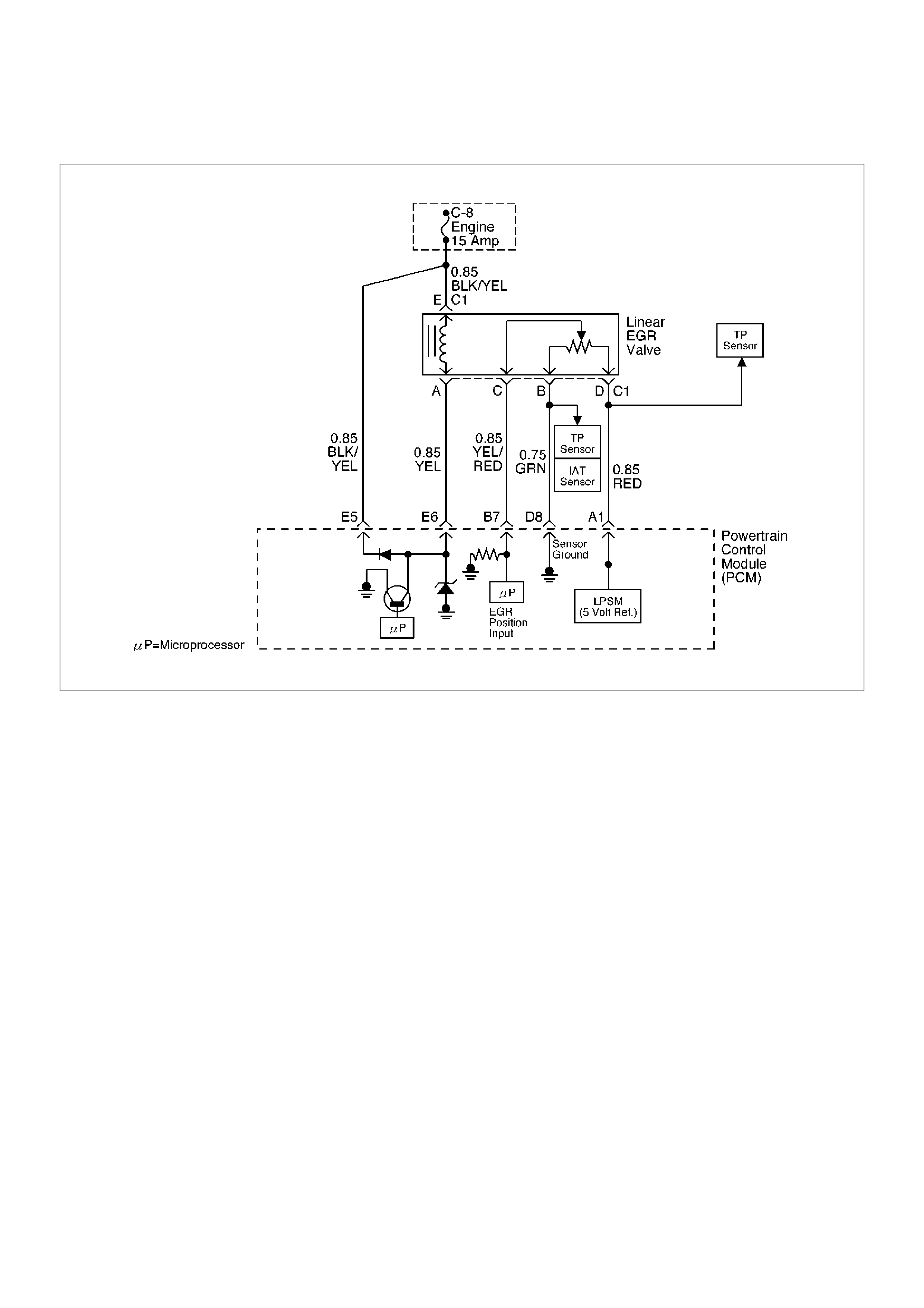
Exhaust Gas Recirculation (EGR) System Check
D06RW106
Circuit Description
A properly operation exhaust gas recirculation (EGR)
system will directly affect the air/fuel requirements of the
engine. Since the exhaust gas introduced into the air/
fuel mixture is an inert gas (contains very little or no
oxygen), less fuel is required to maintain a correct air/
fuel ratio.
Introducing exhaust gas into the combustion chamber
lowers combustion temperatures and reduces the
formation of oxides of nitrogen (NOx) in the exhaust
gas. Lower combustion temperatures also prevent
detonation.
If the EGR pintle were to stay closed, the inert exhaust
gas would be replaced with air and the air/fuel mixture
would be leaner. The powertrain control module (PCM)
would compensate for the lean condition by adding fuel,
resulting in higher long term fuel trim values.
Diagnostic Aids
The EGR valve chart is a check of the EGR system. An
EGR pintle constantly in the closed position could cause
detonation and high emissions of NOx. It could also
result in high long term fuel trim values in the open
throttle cell, but not in the closed throttle cell. An EGR
pintle constantly in the open position would cause a
rough idle. Also, an EGR mounted incorrectly (rotated
180°) could cause rough idle. Check for the following
items:
•EGR passages – Check for restricted or blocked
EGR passages.
•Manifold absolute pressure sensor – A manifold
absolute pressure sensor may shift in calibration
enough to affect fuel delivery. Refer to Manifold
Absolute Pressure Output Check.

Exhaust Gas Recirculation (EGR) System Check
Step Action Value(s) Yes No
1 Check the EGR valve for looseness.
Is the EGR valve Loose? — Go to Step 2 Go to Step 3
2 Tighten the EGR valve.
Is the action complete? — Verify repair —
3 1. Place the transmission selector in Park or Neutral.
2. Start the engine and idle until warm.
3. Using Tech 2, command EGR “50% ON.”
Does the engine idle rough and lose RPMs? —
EGR system
working
properly. No
problem found. Go to Step 4
4 1. Engine “OFF.”
2. Ignition “ON.”
3. Using a test light to ground, check the EGR
harness between the EGR valve and the ignition
feed.
Does the test light illuminate? — Go to Step 6 Go to Step 5
5 Repair the EGR harness ignition feed.
Was the problem corrected? — Verify repair Go to Step 6
6 1. Remove the EGR valve.
2. Visually and physically inspect the EGR valve
pintle, valve passages and adapter for excessive
deposits, obstructions or any restrictions.
Does the EGR valve have excessive deposits,
obstructions or any restrictions? — Go to Step 7 Go to Step 8
7 Clean or replace EGR system components as
necessary.
Was the problem corrected? — Verify repair Go to Step 8
8 1. Ground the EGR valve metal case to battery (–).
2. Using Tech 2, command EGR “ON” and observe
the EGR valve pintle for movement.
Does the EGR valve pintle move according to
command? — Go to Step 9
Go to DTC
P1406 chart
9 1. Remove the EGR inlet and outlet pipes from the
intake and exhaust manifolds.
2. Visually and physically inspect manifold EGR
ports and EGR inlet and outlet pipes for blockage
or restriction caused by excessive deposits or
other damage.
Do the manifold EGR ports or inlet and outlet pipes
have excessive deposits, obstructions, or any
restrictions? — Go to Step 10
EGR system
working
properly. No
problem found.
10 Clean or replace EGR system components as
necessary.
Is the action complete? — Verify repair —
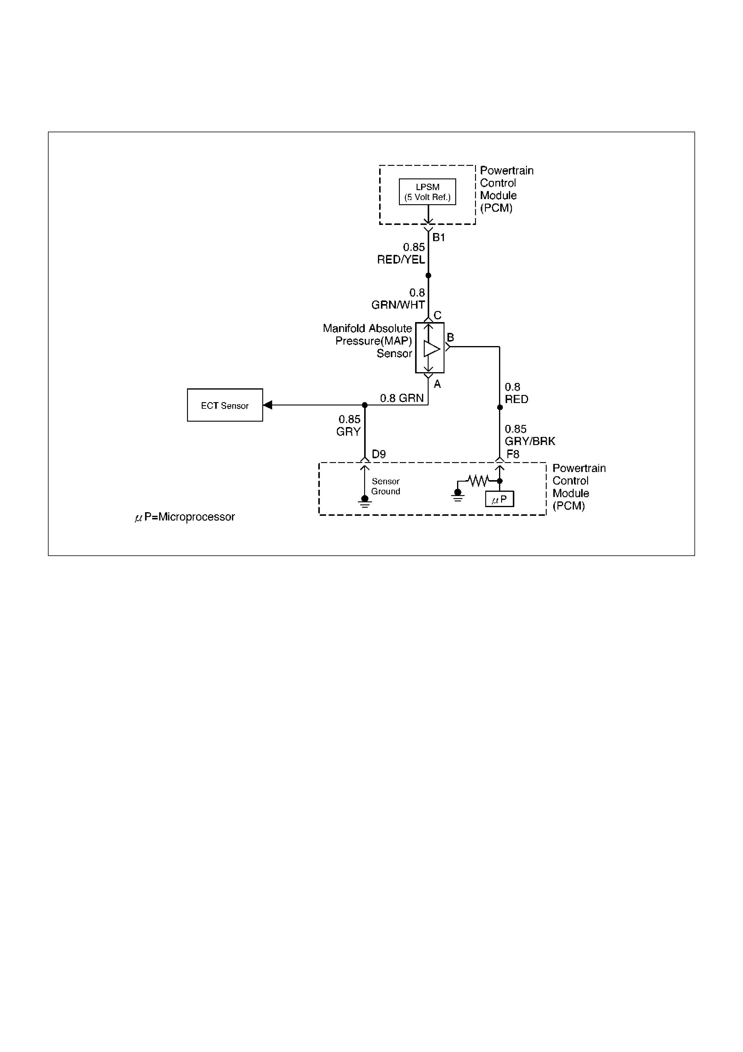
Manifold Absolute Pressure (MAP) Output Check
D06RW102
Circuit Description
The manifold absolute pressure (MAP) sensor
measures the changes in the intake MAP which result
from engine load (intake manifold vacuum) and engine
speed changes; and converts these into a voltage
output. The powertrain control module (PCM) sends a
5-volt reference voltage to the MAP sensor. As the
MAP changes, the output voltage of the sensor also
changes. By monitoring the the sensor output voltage,
the PCM knows the MAP. A lower pressure (low
voltage) output voltage will be about 1-2 volts at idle.
Higher pressure (high voltage) output voltage will be
about 4-4.8 volts at wide open throttle. The MAP sensor
is also used, under certain conditions, to measure
barometric pressure, allowing the PCM to make
adjustments for different altitudes. The PCM uses the
MAP sensor to diagnose proper operation of the EGR
system, in addition to other functions.
Test Description
Important: Be sure to used the same diagnostic test
equipment for all measurements.
The number(s) below refer to the step number(s) on the
Diagnostic Chart.
2. Applying 34 kPa (10 Hg) vacuum to the MAP sensor
should cause the voltage to be 1.5-2.1 volts less
than the voltage at step 1. Upon applying vacuum
to the sensor, the change in voltage should be
instantaneous. A slow voltage change indicates a
faulty sensor.
3. Check the vacuum hose to the sensor for leaking or
restriction, Be sure that no other vacuum devices
are connected to the MAP hose.
Important: Make sure the electrical connector remains
securely fastened.
4. Disconnect the sensor from the bracket. Twist the
sensor with your hand to check for an intermittent
connection. Output changes greater than 0.10 volt
indicate a bad sensor.

Manifold Absolute Pressure (MAP) Output Check
Step Action Value(s) Yes No
1 1. Turn the ignition “OFF”and leave it “OFF” for 15
seconds.
2. Ignition “ON.” Don't crank engine.
3. Tech 2 should indicate a manifold absolute
pressure (MAP) sensor voltage.
4. Compare this scan reading to scan reading of a
known good vehicle obtained using the exact
same procedure as in Steps 1-4.
Is the voltage reading the same +/–0.40 volt? — Go to Step 2 Go to Step 5
2 1. Disconnect the vacuum hose at the MAP sensor
and plug the hose.
2. Connect a hand vacuum pump to the MAP sensor.
3. Start the engine.
4. Apply 34 kPa (10 Hg) of vacuum and note the
voltage change.
Is the voltage change 1.5-2.1 volts less than Step 1? — Go to Step 3 Go to Step 4
3 No trouble found. Check the sensor cover for leakage
or restriction.
Does the hose supply vacuum to the MAP sensor
only? — Go to Step 5 Go to Step 4
4 Repair the material to block.
Is the action complete? — Verify repair —
5 Check the sensor connection.
Is the sensor connection good? — Go to Step 6 Go to Step 7
6 Replace the sensor. Refer to On-Vehicle Service,
MAP Sensor.
Is the action complete? — Verify repair —
7 Repair the poor connection.
Is the action complete? — Verify repair —

PCM Diagnostic Trouble Codes
The following table lists the diagnostic trouble codes
supported by this vehicle application. If any DTCs not
listed here are displayed by a Tech 2, the Tech 2 data
may be faulty; notify the Tech 2 manufacturer of any
DTCs displayed that are not included in the following
table.
A - Emission related P-code, check engine light on as
soon as a failure detected.
B - Emission related P-code, check engine light on if a
failure detected in two consecutive trips.
C - Non emission related P-code, check engine light
on if a failure detected in one trip.
D - Non emission related P-code, no check engine
light, but P-code will be set if a failure detected.
X - Do not check.
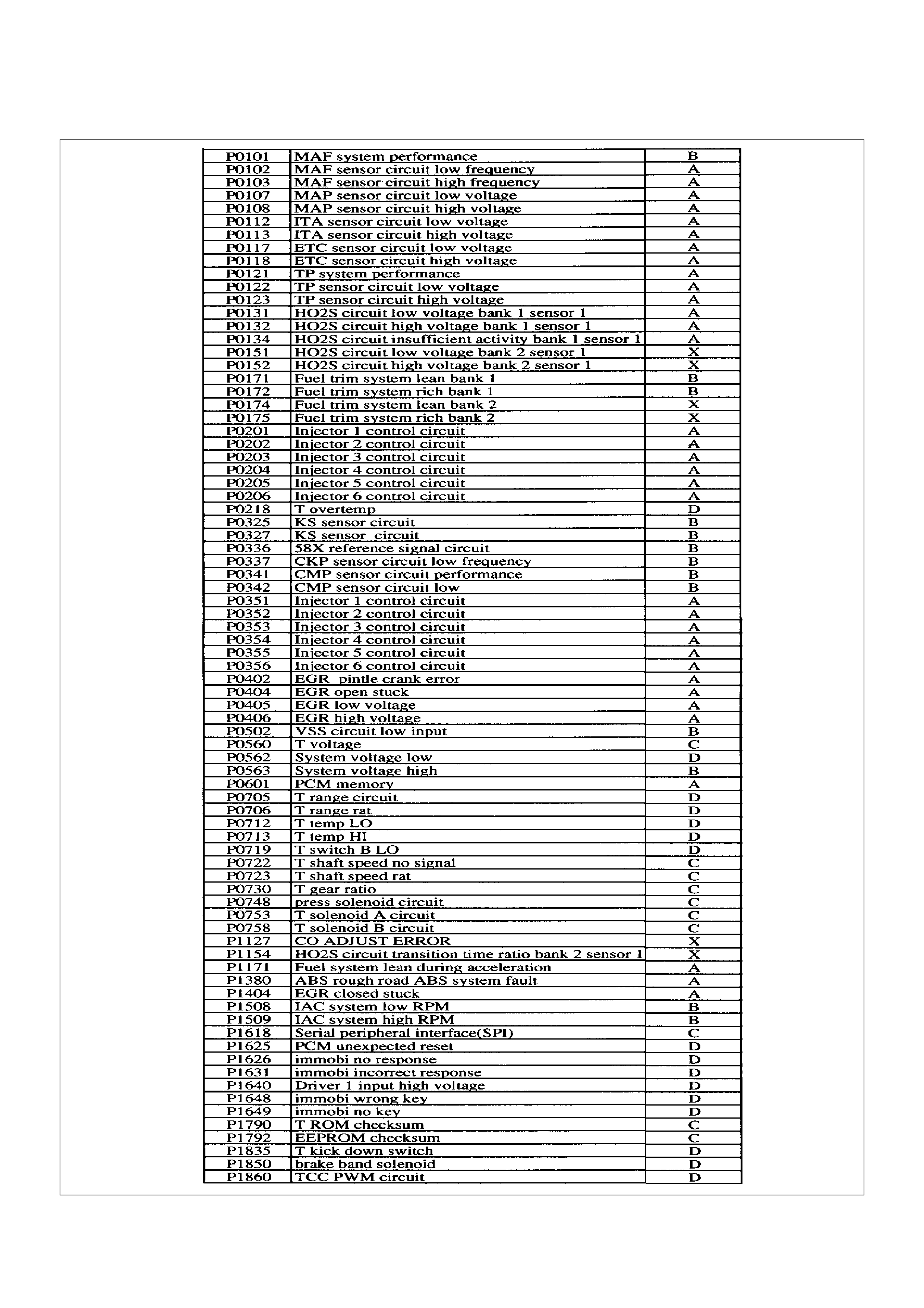
PCM Diagnostic Trouble Codes

Diagnostic Trouble Code (DTC) P0101 MAF System Performance
D06RW103
Circuit Description
The mass air flow (MAF) sensor measures the amount
of air which passes through it into the engine during a
given time. The powertrain control module (PCM) uses
the mass air flow information to monitor engine
operating conditions for fuel delivery calculations. A
large quantity of air entering the engine indicates an
acceleration or high load situation, while a small
quantity or air indicates deceleration or idle.
The MAF sensor produces a frequency signal which
can be monitored using a Tech 2. DTC P0101 will be
set if the signal from the MAF sensor does not match a
predicted value based on throttle position and engine
RPM.
Conditions for Setting the DTC
• The engine is running.
• No TP sensor or MAP sensor DTCs are set.
• The throttle is steady, TP angle doesn't change by
more than 1%.
• System voltage is between 11.5 volts and 16 volts.
• Calculated air flow is between 25 g/second and 40 g/
second.
• Above conditions present for at least 1 second.
• MAF signal frequency indicates an airflow
significantly higher or lower than a predicted value
based on throttle position and engine RPM for a total
of 12.5 seconds over a 25-second period of time.
Action Taken When the DTC Sets
• The PCM will illuminate the malfunction indicator
lamp (MIL) after the second consecutive trip in which
the fault is detected.
• The PCM calculates an airflow value based on idle air
control valve position, throttle position, RPM and
barometric pressure.
• The PCM will store conditions which were present
when the DTC was set as Freeze Frame and in the
Failure Records data.
Conditions for Clearing the MIL/DTC
• DTC P0101 can be cleared by using the Tech 2
“Clear Info” function or by disconnecting the PCM
battery feed.
Diagnostic Aids
An intermittent may be caused by the following:
• Poor connections.
• Mis-routed harness.
• Rubbed through wire insulation.
• Broken wire inside the insulation.

Refer to Intermittents under service category
Symptoms.
Any un-metered air may cause this DTC to set. Check
for the following:
•The duct work at the MAF sensor for leaks.
•An engine vacuum leak.
•The PCV system for vacuum leaks.
•An incorrect PCV valve.
•The engine oil dip stick not fully seated.
•The engine oil fill cap loose or missing.
Test Description
Number(s) below refer to the step number(s) on the
Diagnostic Chart.
2. The MAF system performance or “rationality”
diagnostic uses the MAP sensor signal along with
other input to calculate an expected airflow rate that
is then compared to the actual measured airflow
from the MAF sensor. The first few steps of this
table verify that the MAP sensor is working properly.
6. Using Freeze Frame and/or Failure Records data
may aid in locating an intermittent condition. If the
DTC cannot be duplicated, the information included
in the Freeze Frame and/or Failure Records data
can be useful in determining how many miles since
the DTC set. The Fail Counter and Pass Counter
can also be used to determine how many ignition
cycles the diagnostic reported a pass and/or a fail.
Operate the vehicle within the same Freeze Frame
conditions (RPM, load, vehicle speed , temperature,
etc.) that were noted. This will isolate when the DTC
failed.
For any test that requires back probing the PCM or
component harness connectors, use the Connector
Test Adapter Kit J 35616-A. Using this kit will
prevent any damage to the harness connector
terminals.
7. Any un-metered air may cause this DTC to set.
Check the PVC system for vacuum leaks. Also
inspect the dip stick for being pulled out. Check the
oil fill cap for being loose.
8. Verifies the signal circuit from the MAF sensor
electrical connector to the PCM.
9. Verifies whether a ground and B+ circuit is available.
10. Checks a signal circuit for an open.
11. Checks for a signal circuit shorted to B+.
DTC P0101 – MAF System Performance
StepActionValue(s)YesNo
1 Was the “On-Board Diagnostic (OBD) System Check”
performed? — Go to Step 2
Go to OBD
System Check
2 1. Ignition “ON,” engine “OFF.”
2. Using a Tech 2, select “MAP” from the Engine 1
Data List.
Is the value displayed greater than the value shown? 85kPa Go to Step 3 Go toStep 13
3 1. Remove the MAP sensor from the intake manifold
but leave the electrical harness connected.
2. Connect a hand operated vacuum pump to the
MAP sensor.
3. Observe the MAP display while slowly applying
vacuum up to 20" Hg as indicated on the pump
gauge.
Each 1" of vacuum applied should result in a 3 to
4kPa drop in the MAP sensor value on the Tech 2 and
the value should change smoothly with each increase
in vacuum.
Did the MAP value change smoothly through the
entire range of the test without any erratic readings? — Go to Step 13 Go to Step 4
4 With 20" Hg vacuum applied to the MAP sensor, is the
MAF sensor reading the same or less than the value
shown? 34kPa Go to Step 5 Go to Step 13
5 Disconnect the vacuum source from the MAP sensor.
Does the MAP sensor reading return to its original
value? — Go to Step 6 Go to Step 13

6 1. Ignition “ON,” engine “OFF.”
2. Review the Freeze Frame and/or Failure Records
data for this DTC and note parameters.
3. Ignition “OFF” for 15 seconds.
4. Start the engine and operate the vehicle within the
conditions required for this diagnostic to run, and
as close to the conditions recorded in Freeze
Frame /Failure Records possible. (Special
operating conditions that need to be met before
the PCM will run this diagnostic (where applicable)
are listed in“Conditions for Setting the DTC”).
5. Using the Tech 2, select “DTC,” then enter the
DTC number which was set.
Does the Tech 2 indicate that this diagnostic failed this
ignition? — Go to Step 7
Refer to
Diagnostic Aids
7 1. Check for the following conditions:
• Objects blocking the MAF sensor inlet screen;
• Intake manifold vacuum leaks;
• Vacuum leaks at throttle body;
• Vacuum leaks EGR value flange and pipes.
• Crankcase ventilation valve faulty, missing, or
incorrectly installed.
2. If a problem is found, repair as necessary.
Was a problem found? — Verify repair Go toStep 8
8 1. Ignition “OFF.”
2. Disconnect the MAF sensor connector.
3. Ignition “ON,” engine “OFF.”
4. Using DVM 5-8840-0285-0, measure voltage
between the MAF sensor signal circuit and
chassis ground.
Is the voltage near the specified value? 5 V Go to Step 9 Go toStep 10
9 Connect a test light (5-8840-0607-0) between the
MAF sensor ignition feed and ground circuits at the
MAF sensor harness connector.
Is the test light “ON?” — Go to Step 13 Go toStep 12
10 Is the voltage less than the specified value? 4.5 V Go to Step 13 Go toStep 11
11 1. Ignition “OFF,” disconnect the PCM.
2. Ignition “ON,” engine “OFF.”
3. Measure voltage between the MAF signal circuit
and ground.
Does the voltage measure near the specified value? 0 V Go to Step 13 Go toStep 12
12 Connect a test light (5-8840-0607-0) between the
MAF sensor ignition feed circuit and chassis ground.
Is the test light “ON?” — Go to Step 13 Go toStep 7
13 1. Check for a poor connection at the MAF sensor.
2. If a poor connection is found, replace faulty
terminal(s). Refer to Repair Procedures in
Electrical Diagnosis (8A Cell 5).
Was a poor connection found? — Verify repair Solved
Step Action Value(s) Yes No
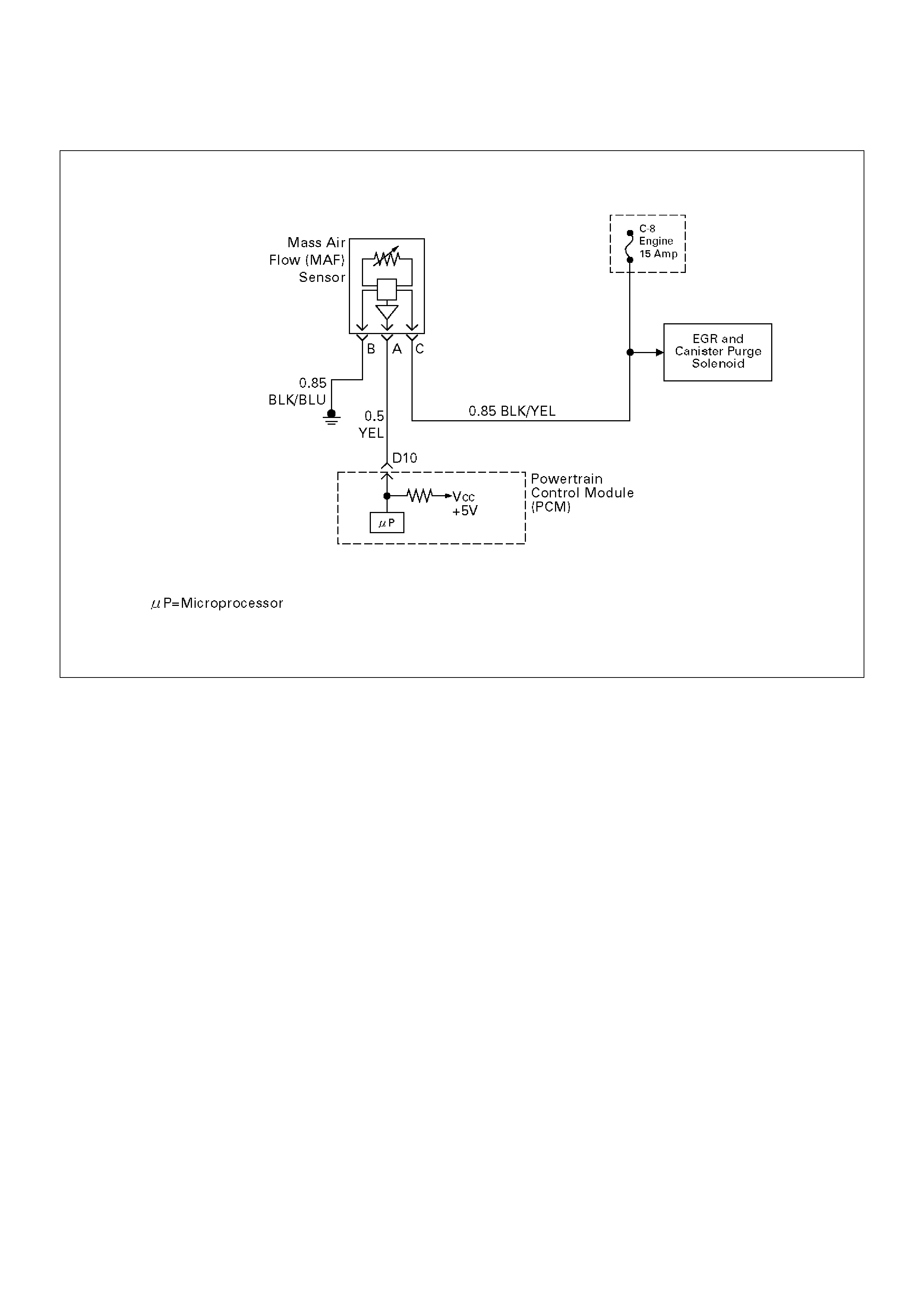
Diagnostic Trouble Code (DTC) P0102 MAF Sensor Circuit Low Frequency
T321122
Circuit Description
The mass air flow (MAF) sensor measures the amount
of air which passes through it into the engine during a
given time. The powertrain control module (PCM) uses
the mass air flow information to monitor engine
operating conditions for fuel delivery calculations. A
large quantity of air entering the engine indicates an
acceleration or high load situation, while a small
quantity of air indicates deceleration or idle.
The MAF sensor produces a frequency signal which
can be monitored using a Tech 2. The frequency will
vary within a range of around 2500Hz at idle to around
1900Hz at maximum engine load. DTC P0102 will be
set if the signal from the MAF sensor is below the
possible range of a normally operating MAF sensor.
Conditions for Setting the DTC
• The engine is running above 500 RPM for greater
than 10 seconds.
• System voltage is above 11.5 volts.
• MAF signal frequency is below 1000Hz for a total of
50-percent of the last 1000 samples monitored. A
sample is taken every cylinder event.
Action Taken When the DTC Sets
• The PCM will illuminate the malfunction indicator
lamp (MIL) the first time the fault is detected.
• The PCM calculates an air flow value based on idle
air control valve position, throttle position, RPM and
barometric pressure.
• The PCM will store conditions which were present
when the DTC was set as Freeze Frame and in the
Failure Records data.
Conditions for Clearing the MIL/DTC
• DTC P0102 can be cleared by using the Tech 2
“Clear Info” function or by disconnecting the PCM
battery feed.
Diagnostic Aids
Check for the following conditions:
• Poor connection at PCM – Inspect harness
connectors for backed-out terminals, improper
mating, broken locks, improperly formed or damaged
terminals, and poor terminal-to-wire connection.
• Misrouted harness – Inspect the MAF sensor harness
to ensure that it is not routed too close to high voltage
wires.
• Damaged harness – Inspect the wiring harness for
damage. If the harness appears to be OK, observe
the Tech 2 while moving connectors and wiring
harnesses related to the MAF sensor. A change in

the display will indicate the location of the fault.
•Plugged intake air duct or filter element – A
wide-open throttle acceleration from a stop should
cause the mass air flow displayed on a Tech 2 to
increase from about 3-6 g/second at idle to 100 g/
second or greater at the time of the 1-2 shift. If not,
check for a restriction.
If DTC P0102 cannot be duplicated, the information
included in the Failure Records data can be useful in
determining vehicle mileage since the DTC was last set.
Test Description
Number(s) below refer to the step number(s) on the
Diagnostic Chart.
2. This step verifies that the problem is present at idle.
4. A voltage reading of less than 4 or over 5 volts at the
MAF sensor signal circuit indicates a fault in the
wiring or a poor connection.
5. This verifies that ignition feed voltage and a good
ground are available at the MAF sensor.
DTC P0102 – MAF Sensor Circuit Low Frequency
StepActionValue(s)YesNo
1 Was the “On-Board Diagnostic (OBD) System Check”
performed? — Go to Step 2
Go to OBD
System Check
2 1. Start the engine.
2. With the engine idling, monitor “MAF Frequency”
display on the Tech 2.
Is the “MAF Frequency” below the specified value? 3g/Sec Go to Step 4 Go to Step 5
3 1. Ignition “ON,” engine “OFF.”
2. Review and record Tech 2 Failure Records data.
3. Operate the vehicle within Failure Records
conditions as noted.
4. Using a Tech 2, monitor “DTC” info for DTC
P0102.
Does the Tech 2 indicate DTC P0102 failed this
ignition? — Go to Step 4
Refer to
Diagnostic Aids
4 1. Ignition “OFF.”
2. Disconnect the MAF sensor connector.
3. Ignition “ON,” engine “OFF.”
4. Using a DVM, measure voltage between the MAF
sensor signal circuit and battery ground.
Is the voltage near the specified value? 5 V Go to Step 5 Go to Step 8
5 Connect a test light between the MAF sensor ignition
feed and ground circuits at the MAF sensor harness
connector.
Is the test light “ON?” — Go to Step 13 Go to Step 6
6 Connect a test light between the MAF sensor ignition
feed circuit and battery ground.
Is the test light “ON?” — Go to Step 12 Go to Step 7
7 1. Check for a poor connection at the MAF sensor.
2. If a poor connection is found, replace the faulty
terminal(s).
Was a poor connection found? — Verify repair Go to Step 11
8 1. Ignition “OFF.”
2. Disconnect the MAF sensor.
3. Disconnect the PCM connector for the MAF signal
circuit.
4. Ignition “ON,” engine “OFF.”
5. With the DVM, measure the voltage between the
MAF signal terminal at the PCM and battery
ground.
Is the voltage under the specified value? 4 V Go to Step 9 Go to Step 10

9 1.Ignition “OFF.”
2.Disconnect the PCM white connector.
3.Ignition “ON.”
4.Check the MAF sensor signal circuit for a short to
5 volts.
Is the action complete?—Verify repair—
10 1.Ignition “OFF.”
2.Disconnect the PCM white connector.
3.Ignition “ON.”
4.Check the MAF sensor signal circuit between the
PCM and the MAF sensor for an open, short to
ground, or short to the MAF ground circuit.
Is the action complete?—Verify repairGo to Step 13
11 Locate and repair the open in the ground circuit to the
MAF sensor.
Is the action complete?—Verify repair—
12 Locate and repair the open in the ignition feed circuit
to the MAF sensor.
Is the action complete?—Verify repair—
13 Replace the MAF sensor.
Is the action complete?—Verify repairGo to Step 14
14 Replace the PCM.
Important: The replacement PCM must be
programmed. Refer to Sections OC1 Service
Programming System and 11A1 6VE1 Immobiliser.
Is the action complete? — Verify repair —
Step Action Value(s) Yes No

Diagnostic Trouble Code (DTC) P0103 MAF Sensor Circuit High Frequency
T321122
Circuit Description
The mass air flow (MAF) sensor measures the amount
of air which passes through it into the engine during a
given time. The powertrain control module (PCM) uses
the mass air flow information to monitor engine
operating conditions for fuel delivery calculations. A
large quantity of air entering the engine indicates an
acceleration or high load situation, while a small
quantity of air indicates deceleration or idle.
The MAF sensor produces a frequency signal which
can be monitored using a Tech 2. The frequency will
vary within a range of around 2500Hz at idle to around
9000Hz at maximum engine load. DTC P0103 will be
set if the signal from the MAF sensor is above the
possible range of a normally operating MAF sensor.
Conditions for Setting the DTC
• The engine is running above 500 RPM for more than
10 seconds.
• System voltage is above 11.5 volts.
• MAF signal frequency is above 10,000Hz (10.0kHz)
for a total of 50 percent of the last 200 samples
monitored. A sample is taken every cylinder event.
Action Taken When the DTC Sets
• The PCM will illuminate the malfunction indicator
lamp (MIL) the first time the fault is detected.
• The PCM calculates an airflow value based on idle air
control valve position, throttle position, RPM and
barometric pressure.
• The PCM will store conditions which were present
when the DTC was set as Freeze Frame and in the
Failure Records data.
Conditions for clearing the MIL/DTC
• DTC P0103 can be cleared by using the Tech 2
“Clear Info” function or by disconnecting the PCM
battery feed.
Diagnostic Aids
If DTC P0103 cannot be duplicated, the information
included in the Failure Records data can be useful in
determining vehicle mileage since the DTC was last set.
Test Description
Number(s) below refer to the step number(s) on the
Diagnostic Chart.
2. This step verifies that the problem is present at idle.
4. A frequency reading with the MAF sensor connector
disconnected indicates an electromagnetic
interfernce (EMI) related fault.

DTC – MAF Sensor Circuit High Frequency
StepActionValue(s)YesNo
1 Was the “On-Board Diagnostic (OBD) System Check”
performed?—Go to Step 2
Go to OBD
System Check
2 1.Ignition “ON,” engine “OFF.”
2.Review and record Tech 2 Failure Records data.
3.Operate the vehicle within Failure Records
conditions as noted.
4.Using a Tech 2, monitor “DTC” info for DTC
P0103.
Does the Tech 2 indicate DTC P0103 failed this
ignition?—Go to Step 3
Refer to
Diagnostic Aids
3 1.Start the engine.
2.With the engine idling, monitor “MAF Frequency”
display on the Tech 2.
Is “MAF Frequency” above the specified value?219g/SecGo to Step 4 Go to Step 7
4 1.Ignition “OFF.”
2.Disconnect the MAF sensor connector.
3.Ignition “ON,” engine idling.
4.Using a Tech 2, monitor “MAF Frequency.”
Does the Tech 2 indicate a “MAF Frequency” at the
specified value?0.0g/SecGo to Step 5 Go to Step 6
5 Replace the MAF sensor.
Is the action complete?—Verify repairGo to Step 8
6 1.Check the MAF harness for incorrect routing near
high voltage components (solenoids, relays,
motors).
2.If incorrect routing is found, correct the harness
routing.
Was a problem found?—Verify repairGo to Step 7
7 1.With the engine idling, monitor “MAF Frequency”
display on the Tech 2.
2.Quickly snap open throttle to wide open throttle
while under a road load and record value.
Does the Tech 2 indicate “MAF Frequency” above the
specified value?219g/SecGo to Step 5 Go to Step 8
8 Replace the PCM.
Important: The replacement PCM must be
programmed. Refer to Sections OC1 Service
Programming System and 11A1 6VE1 Immobiliser.
Is the action complete? — Verify repair —

Diagnostic Trouble Code (DTC) P0107 MAP Sensor Circuit Low Voltage
D06RW102
Circuit Description
The manifold absolute pressure (MAP) sensor responds
to changes in intake manifold pressure (vacuum). The
MAP sensor signal voltage to the powertrain control
module (PCM) varies from below 2 volts at idle (high
vacuum) to above 4 volts with the ignition “ON,” engine
not running or at wide-open throttle (low vacuum).
The MAP sensor is used to determine manifold
pressure changes while the exhaust gas recirculation
(EGR) flow test diagnostic is being run (refer to DTC
P0401), to determine engine vacuum level for some
other diagnostics and to determine barometric pressure
(BARO). The PCM monitors the MAP signals for
voltages outside the normal range of the MAP sensor. If
the PCM detects a MAP signal voltage that is
excessively low, DTC P0107 will be set.
Conditions for Setting the DTC
• No TP sensor DTCs present.
• Engine is running.
• Throttle angle is above 1% if engine speed is less
than 1000RPM.
• Throttle angle is above 2% if engine speed is above
1000RPM.
• The MAP sensor indicates manifold absolute
pressure at or below 11kPa for a total of
approximately 10 seconds over a 16-second period.
• Ignition voltage more than 11 volts.
Action Taken When the DTC Sets
• The PCM will illuminate the malfunction indicator
lamp (MIL) the first time the fault is detected.
• The PCM will default to a BARO value of 79.3kPa.
• The PCM will store conditions which were present
when the DTC was set as Freeze Frame and in the
Failure Records data.
Conditions for Clearing the MIL/DTC
• DTC P0107 can be cleared by using the Tech 2
“Clear Info” function or by disconnecting the PCM
battery feed.
Diagnostic Aids
Check for the following conditions:
• Check for intermittent codes.
• The MAP sensor shares a 5 Volt reference with the
Rough Road Sensor. If these codes are also set, it
could indicate a problem with the 5 Volt reference
circuit .
• The MAP sensor shares a ground with the Rough
Road Sensor, the ECT sensor, and the Transmission

Fluid Temperature sensor.
•Poor connection at PCM – Inspect harness
connectors for backed-out terminals, improper
mating, broken locks, improperly formed or damaged
terminals, and poor terminal-to-wire connection.
•Damaged harness – Inspect the wiring harness for
damage. If the harness appears to be OK, observe
the MAP display on the Tech 2 while moving
connectors and wiring harnesses related to the
sensor. A change in the display will indicate the
location of the fault.
If DTC P0107 cannot be duplicated, the information
included in the Failure Records data can be useful in
determining vehicle mileage since the DTC was last set.
If it is determined that the DTC occurs intermittently,
performing the DTC P0107 Diagnostic Chart may
isolate the cause of the fault.
DTC P0107 – MAP Sensor Circuit Low Voltage
StepActionValue(s)YesNo
1 Was the “On-Board Diagnostic (OBD) System Check”
performed? — Go to Step 2
Go to OBD
System Check
2 1. Ignition “ON,” engine “OFF.”
2. With the throttle closed, observe the MAP value
displayed on the Tech 2.
Is the MAP value near the specified value?
11kPa at sea
level Go to Step 4 Go to Step 3
3 1. Ignition “ON,” engine “OFF.”
2. Review and record Tech 2 Failure Records data.
3. Operate the vehicle within Failure Records
conditions as noted.
4. Using a Tech 2, monitor “Specific DTC” info for
DTC P0107.
Does the Tech 2 indicate DTC P0107 failed? — Go to Step 4
Refer to
Diagnostic Aids
4 1. Ignition “OFF.”
2. Disconnect the MAP sensor electrical connector.
3. Jumper the 5 volt reference “A” circuit and the
MAP signal together at the MAP sensor harness
connector.
4. Ignition “ON.”
5. Observe the MAP value displayed on the Tech 2.
Is the MAP value near the specified value? 5 V 104kPa Go to Step 10 Go to Step 5
5 1. Disconnect the jumper.
2. Connect a test light between B+ and the MAP
sensor signal circuit at the MAP sensor harness
connector.
3. Observe the MAP value displayed on the Tech 2.
Is the MAP value near the specified value. 5 V 104kPa Go to Step 6 Go to Step 8
6 1. Ignition “OFF.”
2. Disconnect the PCM and check the 5 volt
reference “A” circuit for an open or short to
ground.
3. If the 5 volt reference “A” circuit is open or shorted
to ground, repair it as necessary.
Was the 5 volt reference “A” circuit open or shorted to
ground? — Verify repair Go to Step 7
7 Check the 5 volt reference “A” circuit for a poor
connection at the PCM and replace the terminal if
necessary.
Did the terminal require replacement? — Verify repair Go to Step 11

8 1.Ignition “OFF.”
2.Disconnect the PCM, and check the MAP signal
circuit for an open, short to ground, or short to the
sensor ground circuit.
3.If the MAP sensor signal circuit is open or shorted
to ground, repair it as necessary.
Was the MAP signal circuit open or shorted to
ground?—Verify repairGo to Step 9
9 Check the MAP sensor signal circuit for a poor
connection at the PCM and the MAP sensor; replace
the terminal if necessary.
Did the terminal require replacement?—Verify repairGo to Step 11
10 Replace the MAP sensor.
Is the action complete?—Verify repair—
11 Replace the PCM.
Important: The replacement PCM must be
programmed. Refer to Sections OC1 Service
Programming System and 11A1 6VE1 Immobiliser.
Is the action complete? — Verify repair —
Step Action Value(s) Yes No
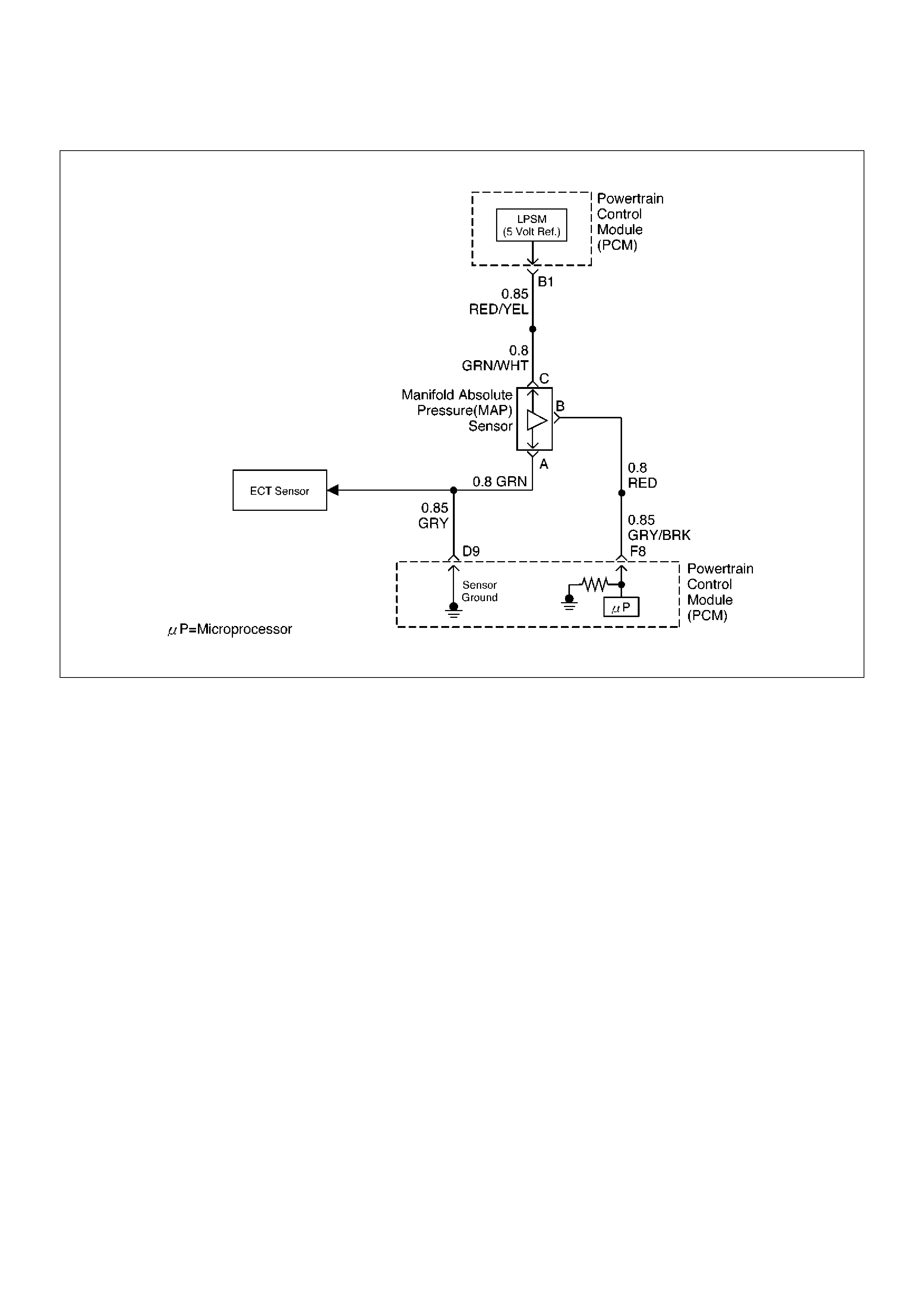
Diagnostic Trouble Code (DTC) P0108 MAP Sensor Circuit High Voltage
D06RW102
Circuit Description
The manifold absolute pressure (MAP) sensor responds
to changes in intake manifold pressure (vacuum). The
MAP sensor signal voltage to the powertrain control
module (PCM) varies from below 2 volts at idle (high
vacuum) to above 4 volts with the key “ON,” engine not
running or at wide-open throttle (low vacuum).
The MAP sensor is used to determine manifold
pressure changes while the linear EGR flow test
diagnostic is being run (refer to DTC P0401), to
determine engine vacuum level for some other
diagnostics and to determine barometric pressure
(BARO). The PCM monitors the MAP signals for
voltages outside the normal range of the MAP sensor. If
the PCM detects a MAP signal voltage that is
excessively high, DTC P0108 will be set.
Conditions for Setting the DTC
• No TP sensor DTCs present.
• Engine is running for more than 10 seconds.
• Throttle position is below 3% if engine speed is below
1000 RPM.
• Throttle position is below 10% if engine speed is
above 1000 RPM.
• The MAP sensor indicates an intermittent manifold
absolute pressure above 80kPa for a total of
approximately 10 seconds over a 16-second period.
Action Taken When the DTC Sets
• The PCM will illuminate the malfunction indicator
lamp (MIL) the first time the fault is detected.
• The PCM will default to a BARO value of 79.3kPa.
• The PCM will store conditions which were present
when the DTC was set as Freeze Frame and in the
Failure Records data.
Conditions for Clearing the MIL/DTC
• DTC P0108 can be cleared by using the Tech 2
“Clear Info” function or by disconnecting the PCM
battery feed.
Diagnostic Aids
Check for the following conditions:
• Poor connection at PCM – Inspect harness
connectors for backed-out terminals, improper
mating, broken locks, improperly formed or damaged
terminals, and poor terminal-to-wire connection.
• Damaged harness – Inspect the wiring harness for
damage. If the harness appears to be OK, observe
the MAP display on the Tech 2 while moving
connectors and wiring harnesses related to the

sensor. A change in the display will indicate the
location of the fault.
If DTC P0108 cannot be duplicated, the information
included in the Failure Records data can be useful in
determining vehicle mileage since the DTC was last set.
If it is determined that the DTC occurs intermittently,
performing the DTC P1108 Diagnostic Chart may
isolate the cause of the fault.

DTC P0108 – MAP Sensor Circuit High Voltage
StepActionValue(s)YesNo
1 Was the “On-Board Diagnostic (OBD) System Check”
performed? — Go to Step 2
Go to OBD
System Check
2 1. If the engine idle is rough, unstable or incorrect,
repair the idle problem before using this chart.
Refer to Symptoms section.
2. With the engine idling, note the MAP value on the
Tech 2.
Is the MAP reading above the specified value? 90kPa Go to Step 4 Go to Step 3
3 1. Ignition “ON,” engine “OFF.”
2. Review and record Tech 2 Failure Records data.
3. Operate the vehicle within Failure Records
conditions as noted.
4. Using a Tech 2, monitor “Specific DTC” info for
DTC P0108.
Does the Tech 2 indicate DTC P0108 failed this
ignition? — Go to Step 4
Refer to
Diagnostic Aids
4 1. Ignition “OFF.”
2. Disconnected the MAP sensor electrical
connector.
3. Ignition “ON.”
4. Note the MAP sensor voltage displayed on the
Tech 2.
Is the MAP sensor voltage at the specified value? 0.0 V 11kPa Go to Step 5 Go to Step 6
5 Probe the sensor ground circuit with a test light to B+.
Is the test light “ON?” — Go to Step 7 Go to Step 9
6 1. Check the MAP signal circuit for a short to voltage
or a short to the 5 volt reference “A” circuit.
2. If the MAP sensor signal circuit is shorted, repair
circuit as necessary.
Was the MAP sensor signal circuit shorted? — Verify repair Go to Step 11
7 1. Check for a poor sensor ground terminal
connection at the MAP sensor electrical
connector.
2. If a problem if found, replace the faulty terminal.
Did the terminal require replacement? — Verify repair Go to Step 8
8 Check for a plugged or leaking vacuum supply to the
MAP sensor.
Is the vacuum supply plugged or leaking? — Verify repair Go to Step 12
9 1. Check for a poor sensor ground terminal
connection at the PCM.
2. If a problem is found, replace the faulty terminal.
Did the terminal require replacement? — Verify repair Go to Step 10
10 1. Check the continuity of the MAP sensor ground
circuit.
2. If the MAP sensor ground circuit measures over 5
ohms, repair open or poor connection.
Was a condition found and corrected? — Verify repair Go to Step 11

11 Replace the PCM.
Important: The replacement PCM must be
programmed. Refer to Sections OC1 Service
Programming System and 11A1 6VE1 Immobiliser.
Is the action complete? — Verify Repair —
12 Replace the MAP sensor.
Is the action complete? — Verify repair —
Step Action Value(s) Yes No
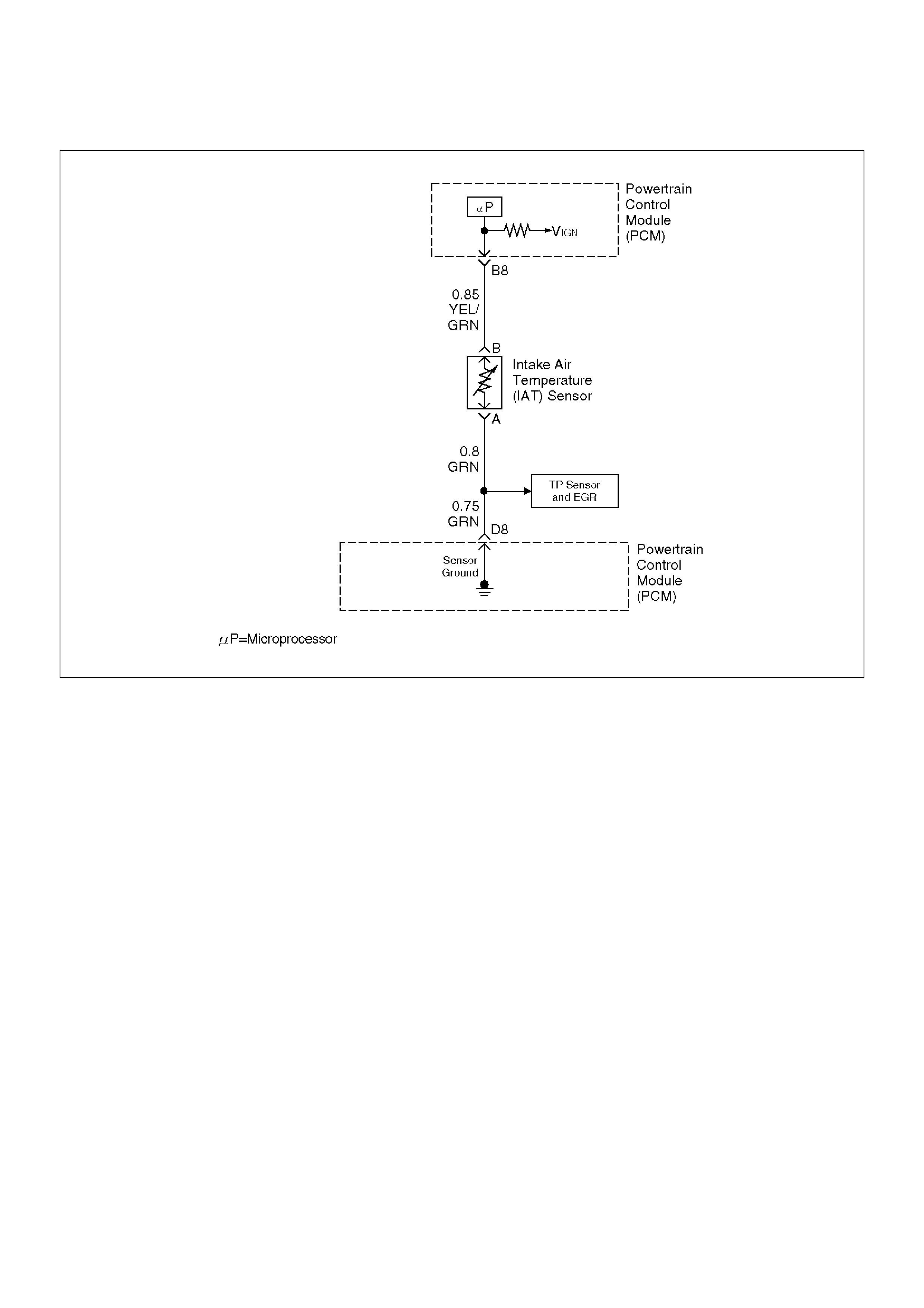
Diagnostic Trouble Code (DTC) P0112 IAT Sensor Circuit Low Voltage
D06RW026
Circuit Description
The intake air temperature (IAT) sensor is a thermistor
which measures the temperature of the air entering the
engine. The powertrain control module (PCM) applies 5
volts through a pull-up resistor to the IAT sensor. When
the intake air is cold, the sensor resistance is high and
the PCM will monitor a high signal voltage on the IAT
signal circuit. If the intake air is warm, the sensor
resistance is lower, causing the PCM to monitor a lower
voltage. DTC P0112 will set when the PCM detects an
excessively low signal voltage on the intake air
temperature sensor signal circuit.
Conditions for Setting the DTC
• The engine has been running for over 2 minutes.
• Vehicle speed is greater than 30 mph (48 km/h) .
• IAT signal voltage indicates and intake air
temperature greater than 148°C (298°F) (about 5
volts) for a total of 12.5 seconds over a 25-second
period of time.
Action Taken When the DTC Sets
• The PCM will illuminate the malfunction indicator
lamp (MIL) the first time the fault is detected.
• The PCM will store conditions which were present
when the DTC was set as Freeze Frame and in the
Failure Records data.
Conditions for Clearing the MIL/DTC
• DTC P0112 can be cleared by using the Tech 2
“Clear Info” function or by disconnecting the PCM
battery feed.
Diagnostic Aids
Check for the following conditions:
• Poor connection at PCM – Inspect harness
connectors for backed-bout terminals, improper
mating, broken locks, improperly formed or damaged
terminals, and poor terminal-to-wire connection.
• Damaged harness – Inspect the wiring harness for
damage. If the harness appears to be OK, observe
the IAT display on the Tech 2 while moving
connectors and wiring harnesses related to the IAT
sensor. A change in the IAT display will indicate the
location of the fault.
If DTC P0112 cannot be duplicated, the information
included in the Failure Records data can be useful in
determining vehicle mileage since the DTC was last set.
Test Description
Number(s) below refer to the step number(s) on the
Diagnostic Chart:

2. Verifies that the fault is present.
3. If DTC P0112 can be repeated only by duplicating
the Failure Records condition, refer to the
Temperature vs. Resistance Value table. The table
may be used to test the IAT sensor at various
temperatures to evaluate the possibility of a “shifted”
sensor that may be stored above or below a certain
temperature. If this is the case, replace the IAT
sensor. If the IAT sensor appears to be OK, the fault
is intermittent; refer to Diagnostic Aids.
Intake Air Temperature Sensor
°C°FOHMS
Temperature vs. Resistance Values (approximate)
100 212 177
80 176 332
60 140 667
45 113 1188
35 95 1802
25 77 2796
15 59 4450
5 41 7280
–5 23 12300
–15 5 21450
–30 –22 52700
–40 –40 100700

DTC P0112–IAT Sensor Circuit Low Voltage
StepActionValue(s)YesNo
1 Was the “On-Board Diagnostic (OBD) System Check”
performed?—Go to Step 2
Go to OBD
System Check
2 1.Ignition “ON,” engine “OFF.”
2.Using a Tech 2, monitor the intake air temperature
(IAT).
Is the intake air temperature greater than the specified
value?
148°C
(283°F)Go to Step 4 Go to Step 3
3 1.Ignition “ON,” engine “OFF.” Review and record
Tech 2 Failure Records data.
2.Operate the vehicle within Failure Records
conditions as noted.
3.Using a Tech 2, monitor the “Specific DTC” info for
DTC P0112.
Does the Tech 2 indicate DTC P0112 failed this
ignition?—
Refer to Test
Description
Refer to
Diagnostic Aids
4 1.Ignition “OFF.”
2.Disconnect the IAT sensor electrical connector.
3.Ignition “ON.”
4.Observe the intake air temperature on the Tech 2.
Is the intake air temperature below the specified
value?
–38°C (–
36°F)Go to Step 6 Go to Step 5
5 1.Ignition “OFF.”
2.Disconnect the PCM electrical connectors.
3.Check the IAT sensor signal circuit for a short to
ground.
Is the IAT sensor signal circuit shorted to ground?—Verify repairGo to Step 7
6 Replace the IAT sensor.
Is the action complete?—Verify repair—
7 Replace the PCM.
Important: The replacement PCM must be
programmed. Refer to Sections OC1 Service
Programming System and 11A1 6VE1 Immobiliser.
Is the action complete? — Verify repair —

Diagnostic Trouble Code (DTC) P0113 IAT Sensor Circuit High Voltage
D06RW026
Circuit Description
The intake air temperature (IAT) sensor is a thermistor
which measures the temperature of the air entering the
engine. The powertrain control module (PCM) applies 5
volts through a pull-up resistor to the IAT sensor. When
the intake air is cold, the sensor resistance is high and
the PCM will monitor a high signal voltage on the IAT
signal circuit. If the intake air is warm, the sensor
resistance is lower causing the PCM to monitor a lower
voltage. DTC P0113 will set when the PCM detects an
excessively high signal voltage on the intake air
temperature sensor signal circuit.
Conditions for Setting the DTC
• The engine has been running for over 4 minutes.
• Vehicle speed is less than 20 mph (32 km/h).
• ECT signal temperature is above 60°C (140°F).
• Mass air flow is less then 20 g/second.
• IAT signal voltage indicates an intake air temperature
less than –39°C (–38°F) for total of 12.5 seconds
over a 25-second period.
Action Taken When the DTC Sets
• The PCM will illuminate the malfunction indicator
lamp (MIL) the first time the fault is detected.
• The PCM will store conditions which were present
when the DTC was set as Freeze Frame and in the
Failure Records data.
Conditions for Clearing the MIL/DTC
• DTC P0113 can be cleared by using the Tech 2
“Clear Info” function or by disconnecting the PCM
battery feed.
Diagnostic Aids
Check for the following conditions:
• The IAT sensor shares a ground with the EGR
position sensor and the TP sensor. Check the
ground if these DTC's are set.
• Poor connection at PCM – Inspect harness
connectors for backed-out terminals, improper
mating, broken locks, improperly formed or damaged
terminals, and poor terminal-to-wire connection.
• Damaged harness – Inspect the wiring harness for
damage. If the harness appears to be OK, observe
the IAT display on the Tech 2 while moving
connectors and wiring harnesses related to the IAT
sensor. A change in the IAT display will indicate the
location of the fault.
If DTC P0113 cannot be duplicated, the information
included in the Failure Records data can be useful in

determining vehicle mileage since the DTC was last set.
Test Description
Number(s) below refer to the step number(s) on the
Diagnostic Chart:
2. Verifies that the fault is present.
3. If DTC P0113 can be repeated only by duplicating
the Failure Records conditions, refer to the
“Temperature vs. Resistance Values” table. The
table may be used to test the IAT sensor at various
temperatures to evaluate the possibility of a “shifted”
sensor that may be open above or below a certain
temperature. If this is the case, replace the IAT
sensor. If the IAT sensor appears to be OK, the fault
is intermittent; refer to Diagnostic Aids.
Intake Air Temperature Sensor
DTC P0113 –IAT Sensor Circuit High Voltage
°C°FOHMS
Temperature vs. Resistance Values (approximate)
100212177
80176332
60140667
451131188
35951802
25772796
15594450
5417280
–52312300
–15521450
–30–2252700
–40–40100700
StepActionValue(s)YesNo
1 Was the “On-Board Diagnostic (OBD) System Check”
performed? — Go to Step 2
Go to OBD
System Check
2 Ignition “ON,” engine “OFF.” Observe the “Intake Air
Temp” display on the Tech 2.
Is the “Intake Air Temp” below the specified value?
–38°C (–
36°F) Go to Step 4 Go to Step 3
3 1. Ignition “ON,” engine “OFF.”
2. Review and record Tech 2 Failure Records data
parameters.
3. Operate the vehicle within Failure Records
conditions as noted.
4. Using a Tech 2, monitor “Specific DTC” info for
DTC P0113.
Does the Tech 2 indicate DTC P0113 failed? —
Refer to Test
Description
Refer to
Diagnostic Aids
4 1. Ignition “OFF.”
2. Disconnect the IAT sensor electrical connector.
3. Jumper the IAT signal circuit and the sensor
ground circuit together at the IAT sensor harness
connector.
4. Ignition “ON.”
5. Observe the “Intake Air Temp” display on the Tech
2.
Is the “Intake Air Temp” at the specified value?
140°C
(284°F) Go to Step 6 Go to Step 5
5 1. Jumper the IAT signal circuit at the IAT sensor
harness connector to chassis ground.
2. Observe the “Intake Air Temp” display on the Tech
2.
Is the “Intake Air Temp” at the specified value?
140°C
(284°F) Go to Step 7 Go to Step 8
6 Check for poor connections at the IAT sensor and
replace terminals if necessary.
Did any terminals require replacement? — Verify repair Go to Step 10

7 1.Ignition “OFF.”
2.Disconnect the PCM, and check the IAT sensor
ground circuit for an open.
3.If the IAT sensor ground circuit is open, repair it as
necessary.
Was the IAT sensor ground circuit open?—Verify repairGo to Step 9
8 1.Ignition “OFF.”
2.Disconnect the PCM, and check the IAT signal
circuit for an open.
3.If the IAT sensor signal circuit is open, repair it as
necessary.
Was the IAT signal circuit open?—Verify repairGo to Step 9
9 Check for a poor sensor ground or IAT signal circuit
terminal connection at the PCM and replace
terminal(s) if necessary.
Did any of the terminals need to be replaced?—Verify repairGo to Step 11
10 Replace the IAT sensor.
Is the action complete?—Verify repair—
11 Replace the PCM.
Important: The replacement PCM must be
programmed. Refer to Sections OC1 Service
Programming System and 11A1 6VE1 Immobiliser.
Is the action complete? — Verify repair —
Step Action Value(s) Yes No
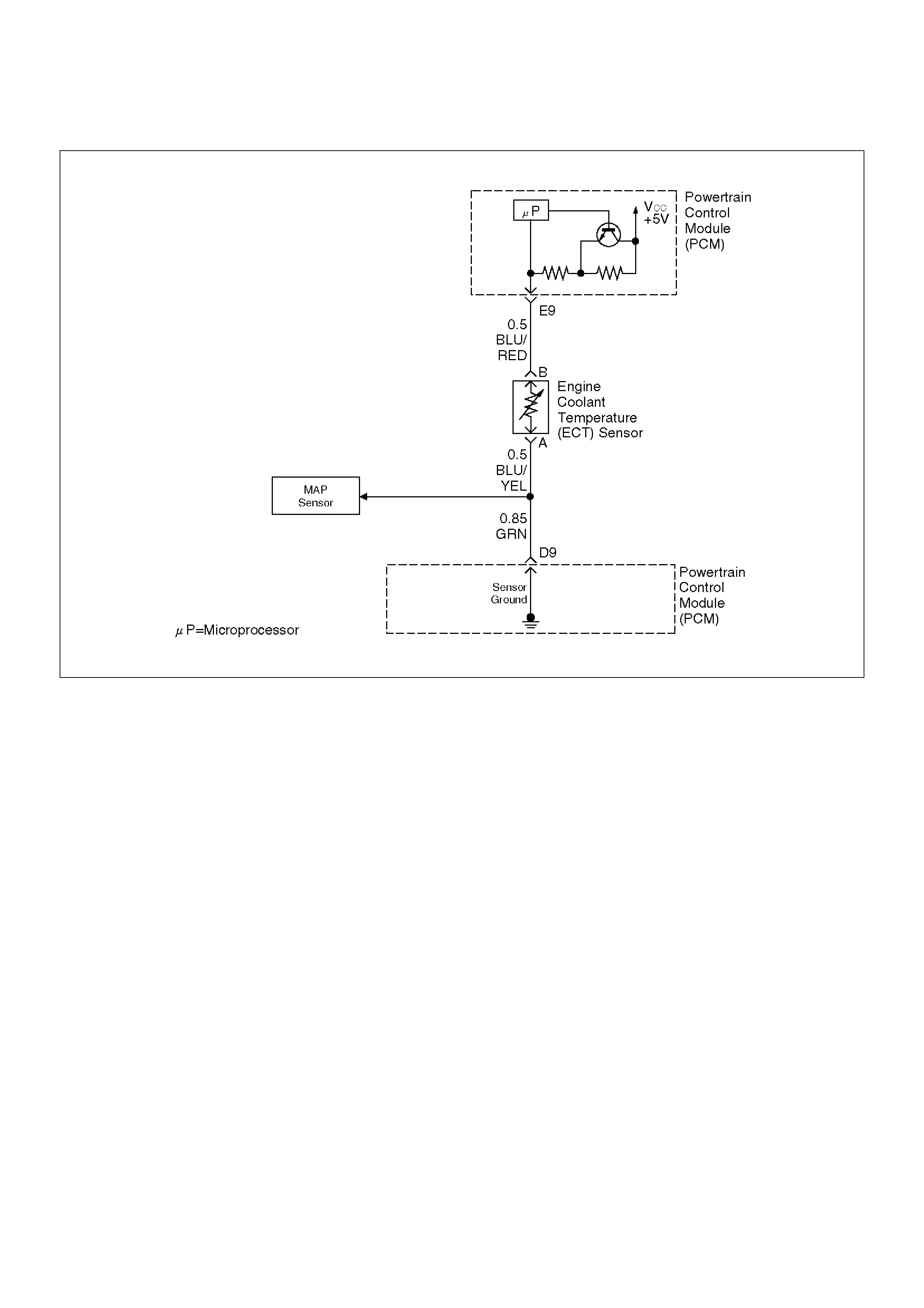
Diagnostic Trouble Code (DTC) P0117 ECT Sensor Circuit Low Voltage
060RY00304
Circuit Description
The engine coolant temperature (ETC) sensor is a
thermistor mounted on a coolant crossover pipe at the
rear of the engine. The powertrain control module
(PCM) applies a voltage (about 5 volts) through a
pull-up resistor to the ECT signal circuit. When the
engine coolant is cold, the sensor (thermistor)
resistance is high, therefore the PCM will measure a
high signal voltage. As the engine coolant warms, the
sensor resistance becomes lower, and the ECT signal
voltage measured at the PCM drops. With a fully
warmed-up engine, the ECT signal voltage should
measure about 1.5 to 2.0 volts.
Conditions for Setting the DTC
• Engine running time is longer than one minute.
• The ECT sensor signal indicates an engine coolant
temperature greater than 150°C (302°F) (about 0.10
V) for a total of 50 seconds over a 100–second
period.
Action Taken When the DTC Sets
• The PCM will illuminate the malfunction indicator
lamp (MIL) the first time the fault is detected.
• The PCM will substitute the ECT reading with a
default engine coolant temperature value. The
default value is based on start-up intake air
temperature and running time.
• The PCM will store conditions which were present
when the DTC was set as Freeze Frame and in the
Failure Records data.
Conditions for Clearing the MIL/DTC
• DTC P0117 can be cleared by using the Tech 2
“Clear Info” function or by disconnecting the PCM
battery feed.
Diagnostic Aids
Check for the following conditions:
• Poor connection at PCM – Inspect harness
connectors for backed-out terminals, improper
mating, broken locks, improperly formed or damaged
terminals, and poor terminal-to-wire connection.
• Damaged harness – Inspect the wiring harness for
damage. If the harness appears to be OK, observe
the ECT display on the Tech 2 while moving
connectors and wiring harnesses related to the ECT
sensor. A change in the ECT display will indicate the
location of the fault.
If DTC P0117 cannot be duplicated, the information
included in the Failure Records data can be useful in
determining vehicle mileage since the DTC was last set.

Test Description
Number(s) below refer to the step number(s) on the
Diagnostic Chart.
2. Verifies that the fault is present.
3. If DTC P0117 can be repeated only by duplicating
the Failure Records conditions, refer to the
“Temperature vs. Resistance Values” table. The
table may be used to test the ECT sensor at various
temperatures to evaluate the possibility of a “shifted”
sensor that may be shorted above or below a certain
temperature. If this is the case, replace the ECT
sensor. If the ECT sensor appears to be OK, the
fault is intermittent; refer to Diagnostic Aids.
Engine Coolant Temperature Sensor
°C°FOHMS
Temperature vs. Resistance Values (approximate)
100 212 177
80 176 332
60 140 667
45 113 1188
35 95 1802
25 77 2796
15 59 4450
5 41 7280
–5 23 12300
–15 5 21450
–30 –22 52700
–40 –40 100700

DTC P0117 – ECT Sensor Low Voltage
StepActionValue(s)YesNo
1 Was the “On-Board Diagnostic (OBD) System Check”
performed?—Go to Step 2
Go to OBD
System Check
2 1.Ignition “ON,” engine “OFF.”
2.Observe the “Eng Cool Temp” display on the Tech
2.
Is the “Eng Cool Temp” below the specified value?
139°C
(282°F)Go to Step 4 Go to Step 3
3 1.Ignition “ON,” engine “OFF.”
2.Review and record Tech 2 Failure Records data.
3.Operate the vehicle within Failure Records
conditions as noted.
4.Using a Tech 2, monitor “Specific DTC” info for
DTC P0117.
Does the Tech 2 indicate DTC P0117 failed this
ignition?—Go to Step 4
Refer to
Diagnostic Aids
4 1.Disconnect the ECT sensor electrical connector.
2.Observe the “Eng Cool Temp” display on the Tech
2.
Is the “Eng Cool Temp” at the specified value?
–39°C (–
38°F)Go to Step 6 Go to Step 5
5 1.Ignition “OFF.”
2.Disconnect the PCM and check the ECT signal
circuit for a short to ground or a short to the sensor
ground circuit.
3.If the ECT signal circuit is shorted. repair it as
necessary.
Was the ECT signal circuit shorted to ground?—Verify repairGo to Step 7
6 Replace the ECT sensor.
Is the action complete?—Verify repair—
7 Replace the PCM.
Important: The replacement PCM must be
programmed. Refer to Sections OC1 Service
Programming System and 11A1 6VE1 Immobiliser.
Is the action complete? — Verify repair —

Diagnostic Trouble Code (DTC) P0118 ECT Sensor Circuit High Voltage
060RY00304
Circuit Description
The engine coolant temperature (ETC) sensor is a
thermistor mounted in on a coolant crossover pipe at
the rear of the engine. The powertrain control module
(PCM) applies a voltage (about 5 volts) through a
pull-up resistor to the ECT signal circuit. When the
engine coolant is cold, the sensor (thermistor)
resistance is high, therefore the PCM will measure a
high signal voltage. As the engine coolant warms, the
sensor resistance becomes less, and the ECT signal
voltage measured at the PCM drops. With a fully
warmed-up engine, the ECT signal voltage should
measure about 1.5 to 2.0 volts.
Conditions for Setting the DTC
• Engine running time is longer than 1.5 minutes.
• The ECT sensor signal indicates an engine coolant
temperature of –39°C (–38°F) or less (about 5 volts)
for a total of 50 seconds over a 100-second period.
Action Taken When the DTC Sets
• The PCM will illuminate the malfunction indicator
lamp (MIL) the first time the fault is detected.
• The PCM will substitute the ECT reading with a
default engine coolant temperature value. The
default value is based on start-up intake air
temperature and running time.
• The PCM will store conditions which were present
when the DTC was set as Freeze Frame and in the
Failure Records data.
Conditions for Clearing the MIL/DTC
• DTC P0118 can be cleared by using the Tech 2
“Clear Info” function or by disconnecting the PCM
battery feed.
Diagnostic Aids
Check for the following conditions:
The ECT shares a ground with the Transmission Fluid
Temperature sensor, the Rough Road sensor, and the
MAP sensor.
Check the ground if these DTCs are also set.
• Poor connection at PCM – Inspect harness
connectors for backed-out terminals, improper
mating, broken locks, improperly formed or damaged
terminals, and poor terminal-to-wire connection.
• Damaged harness – Inspect the wiring harness for
damage. If the harness appears to be OK, observe
the ECT display on the Tech 2 while moving
connectors and wiring harnesses related to the ECT
sensor. A change in the ECT display will indicate the
location of the fault.

If DTC P0118 cannot be duplicated, the information
included in the Failure Records data can be useful in
determining vehicle mileage since the DTC was last set.
If it is determined that the DTC occurs intermittently,
performing the DTC P1115 Diagnostic Chart may isolate
the cause of the fault.
Test Description
Number(s) below refer to the step number(s) on the
Diagnostic Chart.
2. Verifies that the fault is present.
3. If DTC P0118 can be repeated only by duplicating
the Failure Records conditions, refer to the
“Temperature vs. Resistance Value” table. The table
may be used to test the ECT sensor at various
temperatures to evaluate the possibility of a “shifted”
sensor that may be shorted above or below a certain
temperature. If this is the case, replace the ECT
sensor. If the ECT sensor appears to be OK, the
fault is intermittent; refer to Diagnostic Aids.
Engine Coolant Temperature Sensor
DTC P0118 – ECT Sensor Circuit High Voltage
°C°FOHMS
Temperature vs. Resistance Values (approximate)
100212177
80176332
60140667
451131188
35951802
25772796
15594450
5417280
–52312300
–15521450
–30–2252700
–40–40100700
StepActionValue(s)YesNo
1 Was the “On-Board Diagnostic (OBD) System Check”
performed? — Go to Step 2
Go to OBD
System Check
2 1. Ignition “ON,” engine “OFF.”
2. Observe the “Eng Cool Temp” display on the Tech
2.
Is the “Eng Cool Temp” below the specified value?
–39°C (–
38°F) Go to Step 4 Go to Step 3
3 1. Ignition “ON,” engine “OFF.”
2. Review and record Tech 2 Failure Records data.
3. Operate the vehicle within Failure Records
conditions as noted.
4. Using a Tech 2, monitor the “Specific DTC” info for
DTC P0118.
Does the Tech 2 indicate DTC P0118 failed? —
Refer to Test
Description
Refer to
Diagnostic Aids
4 1. Disconnect the ECT sensor electrical connector.
2. Jumper the ECT signal circuit and the sensor
ground circuit together at the ECT sensor harness
connector.
3. Observe the “Eng Cool Temp” display on the Tech
2.
Is the “Eng Cool Temp” at the specified value?
140°C
(284°F) Go to Step 6 Go to Step 5
5 1. Jumper the ECT signal circuit at the ECT sensor
harness connector to chassis ground.
2. Observe the “Eng Cool Temp” display on the Tech
2.
Is the “Eng Cool Temp” at the specified value?
140°C
(284°F) Go to Step 7 Go to Step 8
6 Check for poor connections at the ECT sensor and
replace terminals if necessary.
Did any terminals require replacement? — Verify repair Go to Step 10

7 1.Ignition “OFF.”
2.Disconnect the PCM, and check the ECT sensor
ground circuit for an open.
3.If the ECT sensor ground circuit is open, repair it
as necessary.
Was the ECT sensor ground circuit open?—Verify repairGo to Step 9
8 1.Ignition “OFF.”
2.Disconnect the PCM, and check the ECT signal
circuit for an open.
3.If the ECT sensor signal circuit is open, repair it as
necessary.
Was the ECT signal circuit open?—Verify repairGo to Step 9
9 Check for a poor sensor ground or ECT signal circuit
terminal connection at the PCM and replace
terminal(s) if necessary.
Did any of the terminals need to be replaced?—Verify repairGo to Step 11
10 Replace the ECT sensor.
Is the action complete?—Verify repair—
11 Replace the PCM.
Important: The replacement PCM must be
programmed. Refer to Sections OC1 Service
Programming System and 11A1 6VE1 Immobiliser.
Is the action complete? — Verify repair —
Step Action Value(s) Yes No
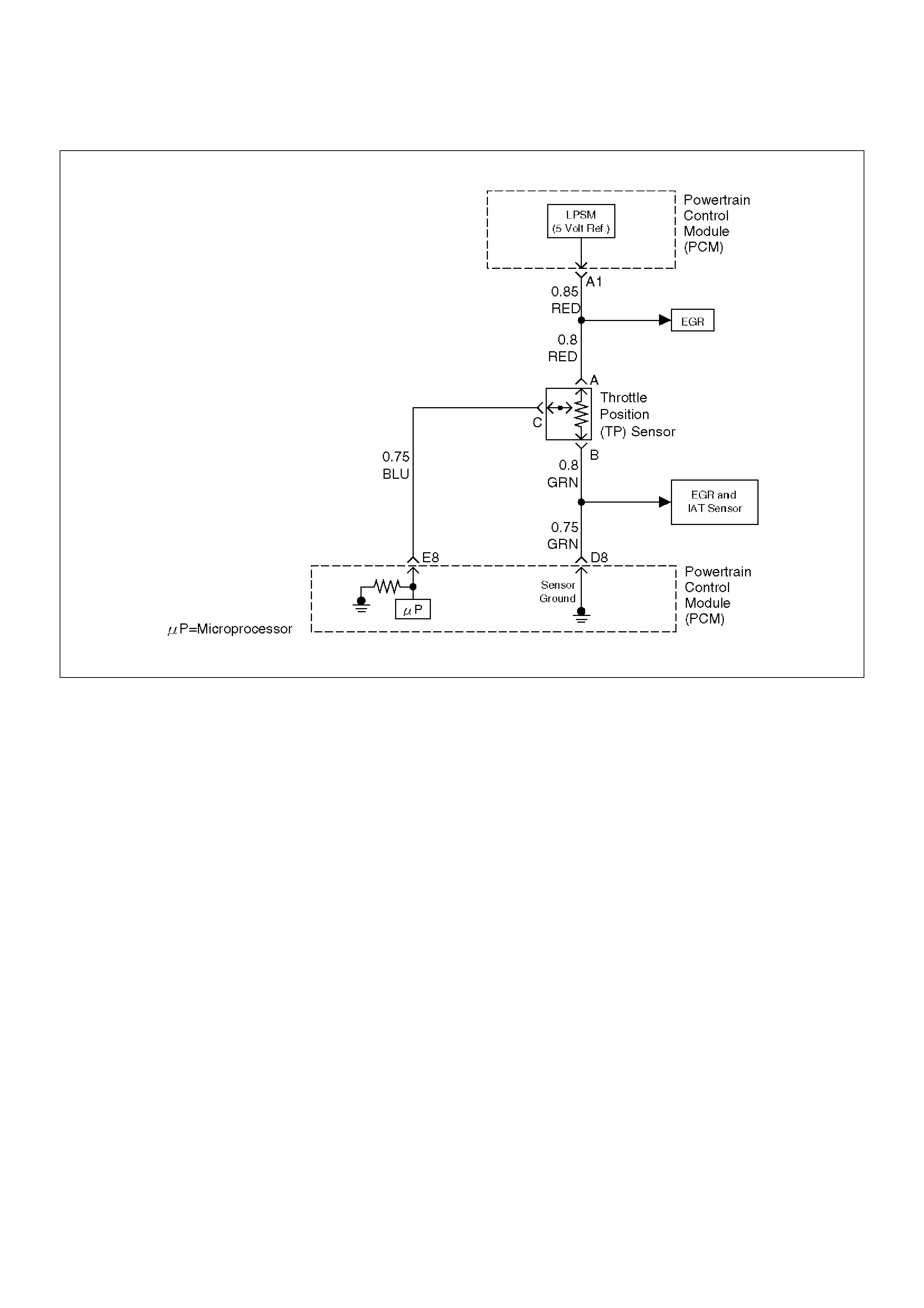
Diagnostic Trouble Code (DTC) P0121 TP System Performance
D06RW028
Circuit Description
The throttle position (TP) sensor circuit provides a
voltage signal that changes relative to throttle blade
angle. The signal voltage will vary from about 0.6 volts
at closed throttle to about 4.5 volts at wide open throttle
(WOT).
The TP signal is used by the powertrain control module
(PCM) for fuel control and many of the PCM-controlled
outputs. The PCM monitors throttle position and
compares actual throttle position from the TP sensor to
a predicted TP value calculated from engine speed. If
the PCM detects an out-of-range condition, DTC P0121
will set.
Conditions for Setting the DTC
• The engine is running.
• No MAP DTCs, or P0121, P0122, P0123 are set.
• MAP reading is below 55kPa.
• Throttle is steady, throttle angle is changing less than
1%.
• Predicted throttle angle is not close to actual throttle
angle.
• Above conditions are present for a total of 12.5
seconds over a 25-second period of time.
Action Taken When the DTC Sets
• The PCM will illuminate the malfunction indicator
lamp (MIL) after the second consecutive trip in which
the fault is detected.
• The PCM will store conditions which were present
when the DTC was set as Freeze Frame and in the
Failure Records data.
• The PCM will use a default throttle position based on
mass air flow and RPM.
Conditions for Clearing the MIL/DTC
• DTC P0121 can be cleared by using the Tech 2
“Clear info ” function or by disconnecting the PCM
battery feed.
Diagnostic Aids
Check for the following conditions:
• Skewed MAP signal or faulty Map sensor – An
incorrect MAP signal may cause the PCM to
incorrectly calculate the predicted TP sensor value
during high engine load situations. Check for an
unusually low MAP reading. This condition can
cause DTC P0121 to be set.
• Poor connection at PCM – Inspect harness
connectors for backed-out terminals, improper
mating, broken locks improperly formed or damaged

terminals, and poor terminal-to-wire connection.
•Damaged harness – Inspect the wiring harness for
damage. If the harness appears to be OK, observe
the ECT display on the Tech 2 while moving
connectors and wiring harnesses related to the
sensor. A change in the display will indicate the
location of the fault.
If DTC P0121 cannot be duplicated, the information
included in the Failure Records data can be useful in
determining vehicle mileage since the DTC was last set.
DTC P0121 –TP System Performance
StepActionValue(s)YesNo
1 Was the “On-Board Diagnostic (OBD) System Check”
performed? — Go to Step 2
Go to OBD
System Check
2 1. Ignition “ON,” engine not running.
2. Observe the MAP reading on the Tech 2.
Is the MAP reading less than the specified value? 65kPa Go to Step 3 Go to Step 6
3 1. Disconnected the MAP sensor.
2. Connect a test light between the 5 volt reference
“A” circuit and the MAP signal circuit at the MAP
sensor harness connector.
3. Observe the MAP reading on the Tech 2.
Is the MAP reading less than the specified value? 65kPa Go to Step 5 Go to Step 4
4 1. Check the MAP signal circuit between the PCM
and the MAP sensor for an open, short to ground,
or short to the MAP ground circuit.
2. If the MAP signal circuit is open or shorted, repair
it as necessary.
Was the MAP signal circuit open or shorted? — Verify repair Go to Step 12
5 Replace the MAP sensor.
Is the action complete? — Verify repair —
6 Observe the TP angle reading on the Tech 2 while
slowly opening the throttle.
Does the TP angle increase steadily and evenly from
the closed throttle value to the wide open throttle
value?
Closed
throttle = 0%
Wide open
throttle =
100%
Refer to
Diagnostic Aids Go to Step 7
7 1. Disconnect the TP sensor.
2. Observe the TP sensor reading on the Tech 2.
Is the TP sensor reading near the specified value? 0 V Go to Step 8 Go to Step 9
8 1. Connect a test light between the 5 volt reference
“A” circuit and the TP sensor signal circuit at the
TP sensor harness connector.
2. Observe the TP sensor reading on the Tech 2.
Is the TP sensor reading at the specified value? 5 V Go to Step 11 Go to Step 10
9 Check the following items:
1. TP signal circuit for a short to voltage.
2. TP sensor ground circuit for high resistance
between the PCM and the TP sensor.
3. TP sensor ground circuit for a poor connection.
4. If a problem is found, repair wiring harness as
necessary.
Was a problem found? — Verify repair Go to Step 12

10 Check the following items:
1.TP signal circuit or 5 volt reference “A” circuit for a
poor connection.
2.TP signal circuit or 5 volt reference “A” circuit for
high resistance between the PCM and the TP
sensor.
3.If a problem is found, repair wiring harness as
necessary.
Was a problem found?—Verify repairGo to Step 12
11 Replace the TP sensor.
Is the action complete?—Verify repair—
12 Replace the PCM.
Important: The replacement PCM must be
programmed. Refer to Sections OC1 Service
Programming System and 11A1 6VE1 Immobiliser.
Is the action complete? — Verify repair —
Step Action Value(s) Yes No

Diagnostic Trouble Code (DTC) P0122 TP Sensor Circuit Low Voltage
D06RW028
Circuit Description
The throttle position (TP) sensor circuit provides a
voltage signal that changes relative to throttle blade
angle. The signal voltage will vary from below 0.6 volts
at closed throttle to about 4.5 volts at wide open throttle
(WOT).
The TP signal is used by the powertrain control module
(PCM) for fuel control and many of the PCM–controlled
outputs.
Conditions for Setting the DTC
• The ignition is “ON.”
• TP sensor signal voltage is less than 0.22 volt for a
total of 0.78 second over a 1.5-second period.
Action Taken When the DTC Sets
• The PCM will illuminate the malfunction indicator
lamp (MIL) the first time the fault is detected.
• The PCM will store conditions which were present
when the DTC was set as Freeze Frame and in the
Failure Records data.
• The PCM will use a default throttle position based on
mass air flow and RPM.
Conditions for Clearing the MIL/DTC
• DTC P0122 can be cleared by using the Tech 2
“Clear Info” function or by disconnecting the PCM
battery feed.
Diagnostic Aids
Check for the following conditions:
• Check intermittent codes.
• The TP sensor shares a 5 Volt reference with the
EGR position sensor. Check the 5 Volt reference if
these DTCs are also set.
• The TP sensor shares a ground with the IAT sensor,
the EGR position sensor.
• Poor connection at PCM – Inspect harness
connectors for backed-out terminals, improper
mating, broken locks, improperly formed or damaged
terminals, and poor terminal-to-wire connection.
• Damaged harness – Inspect the wiring harness for
damage. If the harness appears to be OK, observe
the throttle position display on the Tech 2 while
moving connectors and wiring harnesses related to
the TP sensor. A change in the display will indicate
the location of the fault.
If DTC P0122 cannot be duplicated, the information
included in the Failure Records data can be useful in
determining vehicle mileage since the DTC was last set.

DTC P0122 –TP Sensor Circuit Low Voltage
StepActionValue(s)YesNo
1 Was the “On-Board Diagnostic (OBD) System Check”
performed? — Go to Step 2
Go to OBD
System Check
2 1. Ignition “ON,” engine “OFF.”
2. With the throttle closed, observe the “TP Sensor”
display on the Tech 2.
Is the “TP Sensor” below the specified value? 0.22 V Go to Step 4 Go to Step 3
3 1. Ignition “ON,” engine “OFF.”
2. Review and record Tech 2 Failure Records data.
3. Operate the vehicle within Failure Records
conditions as noted.
4. Using a Tech 2, monitor the “DTC” info for DTC
P0122.
Does the Tech 2 indicate DTC P0122 failed? — Go to Step 4
Refer to
Diagnostic Aids
4 1. Ignition “OFF.”
2. Disconnect the TP sensor electrical connector.
3. Jumper the 5 volt reference “A” circuit and the TP
signal together at the TP sensor harness
connector.
4. Ignition “ON.”
Observe the “TP Sensor” display on the Tech 2.
Is the “TP Sensor” at the specified value? 5 V Go to Step 10 Go to Step 5
5 1. Disconnect jumper.
2. Connect a test light between B+ and the TP
sensor signal circuit at the TP sensor harness
connector.
Observe the “TP Sensor” display on the Tech 2.
Is the “TP Sensor” at the specified value? 5 V Go to Step 6 Go to Step 8
6 1. Ignition “OFF.”
2. Disconnect the PCM and check the 5 volt
reference “A” circuit for an open or short to
ground.
3. If the 5 volt reference “A” circuit is open or shorted
to ground, repair it as necessary.
Was the 5 volt reference “A” circuit open or shorted to
ground? — Verify repair Go to Step 7
7 Check the 5 volt reference “A” circuit for a poor
connection at the PCM and replace the terminal if
necessary.
Did the terminal require replacement? — Verify repair Go to Step 12
8 1. Ignition “OFF.”
2. Disconnect the PCM, and check the TP signal
circuit for an open, short to ground, or short to the
sensor ground circuit.
3. If the TP sensor signal circuit is open or shorted to
ground, repair it as necessary.
Was the TP signal circuit open or shorted to ground? — Verify repair Go to Step 9
9 Check the TP sensor signal circuit for a poor
connection at the PCM and replace the terminal if
necessary.
Did the terminal require replacement? — Verify repair Go to Step 12

10 Check the TP sensor signal circuit for a poor
connection at the TP sensor and replace the terminal
if necessary.
Did the terminal require replacement?—Verify repairGo to Step 11
11 Replace the TP sensor.
Is the action complete?—Verify repair—
12 Replace the PCM.
Important: The replacement PCM must be
programmed. Refer to Sections OC1 Service
Programming System and 11A1 6VE1 Immobiliser.
Is the action complete? — Verify repair —
Step Action Value(s) Yes No

Diagnostic Trouble Code (DTC) P0123 TP Sensor Circuit High Voltage
D06RW028
Circuit Description
The throttle position (TP) sensor circuit provides a
voltage signal that changes relative to throttle blade
angle. The signal voltage will vary from about 0.6 volts
at closed throttle to about 4.5 volts at wide open throttle
(WOT).
The TP signal is one of the most important inputs used
by the powertrain control module (PCM) for fuel control
and many of the PCM-controlled outputs.
Conditions for Setting the DTC
• The ignition is “ON.”
• TP sensor signal voltage is greater than 4.88 volts for
a total of 0.78 second over a 1.5-second period.
Action Taken When the DTC Sets
• The PCM will illuminate the malfunction indicator
lamp (MIL) the first time the fault is detected.
• The PCM will store conditions which were present
when the DTC was set as Freeze Frame and in the
Failure Records data.
• The PCM will use a default throttle position based on
mass air flow and RPM.
Conditions for Clearing the MIL/DTC
• DTC P0123 can be cleared by using the Tech 2
“Clear Info” function or by disconnecting the PCM
battery feed.
Diagnostic Aids
Check for the following conditions:
• Check intermittent codes.
• The TP sensor shares a 5 Volt reference with the
EGR position sensor. Check the 5 Volt reference if
these DTCs are also set.
• The TP sensor shares a ground with the IAT sensor
and the EGR position sensor. Check the ground if
these other DTCs are also set.
• Poor connection at PCM – Inspect harness
connectors for backed-out terminals, improper
mating, broken locks, improperly formed or damaged
terminals, and poor terminal-to-wire connection.
• Damaged harness – Inspect the wiring harness for
damage. If the harness appears to be OK, observe
the TP sensor display on the Tech 2 while moving
connectors and wiring harnesses related to the TP
sensor. A change in the display will indicate the
location of the fault.
• Faulty TP sensor – With the ignition key “ON,” engine
“OFF,” observe the TP sensor display on the Tech 2

while slowly depressing the accelerator to wide open
throttle. If a voltage over 4.88 volts is seen at any
point in normal accelerator travel, replace the TP
sensor.
If DTC P0123 cannot be duplicated, the information
included in the Failure Records data can be useful in
determining vehicle mileage since the DTC was last set.
Test Description
Number (s) below refer to the step number(s) on the
Diagnostic Chart.
7. Components that share the TP sensor 5 volt
reference “A” circuit include the following device:
•EGR valve
Disconnect the component while observing the TP
sensor display on the Tech 2. If the reading changes
drastically when this component is disconnected,
replace the component that affected the reading.
DTC P0123 – TP Sensor Circuit High Voltage
StepActionValue(s)YesNo
1 Was the “On-Board Diagnostic (OBD) System Check”
performed? — Go to Step 2
Go to OBD
System Check
2 1. Ignition “ON,” engine “OFF.”
2. With the throttle closed, observe the “TP Sensor”
display on the Tech 2.
Is the “TP Sensor” above the specified value? 4.88 V Go to Step 4 Go to Step 3
3 1. Ignition “ON,” engine “OFF.”
2. Review and record Tech 2 Failure Records data.
3. Operate the vehicle within Failure Records
conditions as noted.
4. Using a Tech 2, monitor “Specific DTC” info for
DTC P0123.
Does the Tech 2 indicate DTC P0123 failed. — Go to Step 4
Refer to
Diagnostic Aids
4 1. Disconnect the TP sensor electrical connector.
2. Observe the “TP Sensor” display on the Tech 2.
Is the “TP Sensor” near the specified value? 0 V Go to Step 5 Go to Step 6
5 Probe the sensor ground circuit at the TP sensor
harness connector with a test light connected to B+.
Is the test light “ON?” — Go to Step 7 Go to Step 10
6 1. Ignition “OFF,” disconnect the PCM.
2. Ignition “ON,” engine “OFF.”
3. Check for a short to voltage on the TP sensor
signal circuit.
4. If the TP sensor signal circuit is shorted, repair it
as necessary.
Was the TP sensor signal circuit shorted? — Verify repair Go to Step 12
7 1. Ignition “ON.”
2. Monitor the “TP Sensor” Tech 2 display while
disconnecting each of the components that share
the 5 volt reference “A” circuit (one at a time).
3. If the “TP Sensor” Tech 2 display changes,
replace the component that caused the display to
change when disconnected.
Does disconnecting any of these components cause
the “TP Sensor” display to change? — Verify repair Go to Step 8

8 1.Ignition “OFF,” disconnect the PCM.
2.Ignition “ON,” engine “OFF.”
3.Check for a short to B+ on the 5 volt reference “A”
circuit.
4.If the 5 volt reference “A” circuit is shorted, repair it
as necessary.
Was the 5 volt reference “A” circuit shorted?—Verify repairGo to Step 9
9 Check for poor electrical connections at the TP sensor
and replace terminals if necessary.
Did any terminals require replacement?—Verify repairGo to Step 11
10 1.Ignition “OFF.”
2.Disconnect the PCM, and check for an open
sensor ground circuit to the TP sensor.
3.If a problem is found, repair it as necessary.
Was the sensor ground circuit to the TP sensor open?—Verify repairGo to Step 12
11 Replace the TP sensor.
Is the action complete?—Verify repair—
12 Replace the PCM.
Important: The replacement PCM must be
programmed. Refer to Sections OC1 Service
Programming System and 11A1 6VE1 Immobiliser.
Is the action complete? — Verify repair —
Step Action Value(s) Yes No

Diagnostic Trouble Code (DTC) P0131 HO2S Circuit Low Voltage Bank 1 Sensor 1
060RW236
Circuit Description
The powertrain control module (PCM) supplies a bias
voltage of about 450 mV between the heated oxygen
sensor (HO2S) signal high and signal low circuits.
When measured with a 10 megaohm digital voltmeter,
this may display as low as 350 mV. The oxygen sensor
varies the voltage within a range of about 1000 mV
when the exhaust is rich, down through about 10 mV
when exhaust is lean. The PCM constantly monitors
the HO2S signal during “closed loop” operation and
compensates for a rich or lean condition by decreasing
or increasing injector pulse width as necessary. If the
Bank 1 HO2S 1 voltage remains excessively low for an
extended period of time, DTC P0131 will be set.
Conditions for Setting the DTC
•No related DTCs.
•Vehicle is operating in “closed loop.”
•Engine coolant temperature is above 60°C (140°F).
•“Closed loop” commanded air/fuel ratio is between
14.5 and 14.8.
•Throttle angle is between 3% and 19%.
•Bank 1 HO2S 1 signal voltage remains below 22 mV
during normal “closed loop” operation for a total of 77
seconds over a 90-second period of time.
Action Taken When the DTC Sets
•The PCM will illuminate the malfunction indicator
lamp (MIL) the first time the fault is detected.
•The PCM will store conditions which were present
when the DTC was set as Freeze Frame and in the
Failure Records data.
•“Open loop” fuel control will be in effect.
Conditions for Clearing the MIL/DTC
•DTC P0131 can be cleared by using the Tech 2
“Clear Info” function or by disconnecting the PCM
battery feed.
Diagnostic Aids
Check for the following conditions:
•Heated oxygen sensor wiring – The sensor pigtail
may be routed incorrectly and contacting the exhaust
system.
•Poor PCM to engine block grounds.
•Fuel pressure – The system will go lean if pressure is
too low. The PCM can compensate for some
decrease. However, If fuel pressure is too low, a
DTC P0131 may be set. Refer to Fuel System
Diagnosis.
• Lean injector(s) – Perform “Injector Balance Test.”

•Vacuum leaks – Check for disconnected or damaged
vacuum hoses and for vacuum leaks at the intake
manifold, throttle body, EGR system, and PCV
system.
•Exhaust leaks – An exhaust leak may cause outside
air to be pulled into the exhaust gas stream past the
HO2S, causing the system to appear lean. Check for
exhaust leaks that may cause a false lean condition
to be indicated.
•MAF sensor – The system can go lean if the MAF
sensor signal indicates an engine airfiow
measurement that is not correct. Disconnect the
MAF sensor to see if the lean condition is corrected.
If so, replace the MAF sensor.
•Fuel contamination – Water, even in small amounts,
can be delivered to the fuel injectors. The water can
cause a lean exhaust to be indicated. Excessive
alcohol in the fuel can also cause this condition.
Refer to Fuel System Diagnosis for the procedure to
check for fuel contamination.
•If none of the above conditions are present, replace
the affected HO2S.
Test Description
Number(s) below refer to step numbers on the
diagnostic chart.
3. DTC P0131 failing during operation may indicate a
condition described in the “Diagnostic Aids” above.
If the DTC P0131 test passes while the Failure
Records conditions are being duplicated, an
intermittent condition is indicated.
Reviewing the Failure Records vehicle mileage since
the diagnostic test last failed may help determine how
often the condition that caused the DTC to be set
occurs. This may assist in diagnosing the condition.
DTC P0131 –HO2S Circuit Low Voltage Bank 1 Sensor 1
StepActionValue(s)YesNo
1 Was the “On-Board Diagnostic (OBD) System Check”
performed? — Go to Step 2
Go to OBD
System Check
2 1. Install the Tech 2.
2. Run the engine at operating temperature.
3. Operate the vehicle within the parameters
specified under “Conditions for Setting the DTC”
criteria included in Diagnostic Support.
4. Using a Tech 2, monitor Bank 1 HO2S 1 voltage.
Does the Bank 1 HO2S 1 voltage remain below the
specified value? 22 mV Go to Step 4 Go to Step 3
3 1. Ignition “ON,” engine “OFF,” review and record
Tech 2 Failure Records data and note parameters.
2. Operate the vehicle within Failure Records
conditions as noted.
3. Using a Tech 2, monitor “Specific DTC” info for
DTC P0131 until the DTC P0131 test runs.
Note test result.
Does Tech 2 indicate DTC P0131 failed this ignition? — Go to Step 4
Refer to
Diagnostic Aids
4 1. Turn the ignition “OFF.”
2. Disconnect the PCM.
3. Check the Bank 1 HO2S 1 high and low circuits for
a short to ground or a short to the heater ground
circuit.
Are the Bank 1 HO2S 1 signal circuits shorted to
ground? — Go to Step 5 Go to Step 6
5 Repair the Bank 1 HO2S 1 signal circuit.
Is the action complete? — Verify repair —
6 1. Turn the ignition “OFF,” HO2S 1 and PCM
disconnected.
2. Check for continuity between the high and low
signal circuits.
Was there continuity between the high and low
circuits? — Go to Step 7 Go to Step 8

7 Repair the short between the high and low circuits.
Is the action complete?—Verify repair—
8 1.Ignition “OFF.”
2.Reconnect the PCM, leave the sensor
disconnected.
3.Ignition “ON.”
Does the Tech 2 indicate Bank 1 HO2S 1 voltage
between the specified values?425-475 mV
Refer to
Diagnostic Aids Go to Step 9
9 Replace the PCM.
Important: The replacement PCM must be
programmed. Refer to Sections OC1 Service
Programming System and 11A1 6VE1 Immobiliser.
Is the action complete? — Verify repair —
Step Action Value(s) Yes No
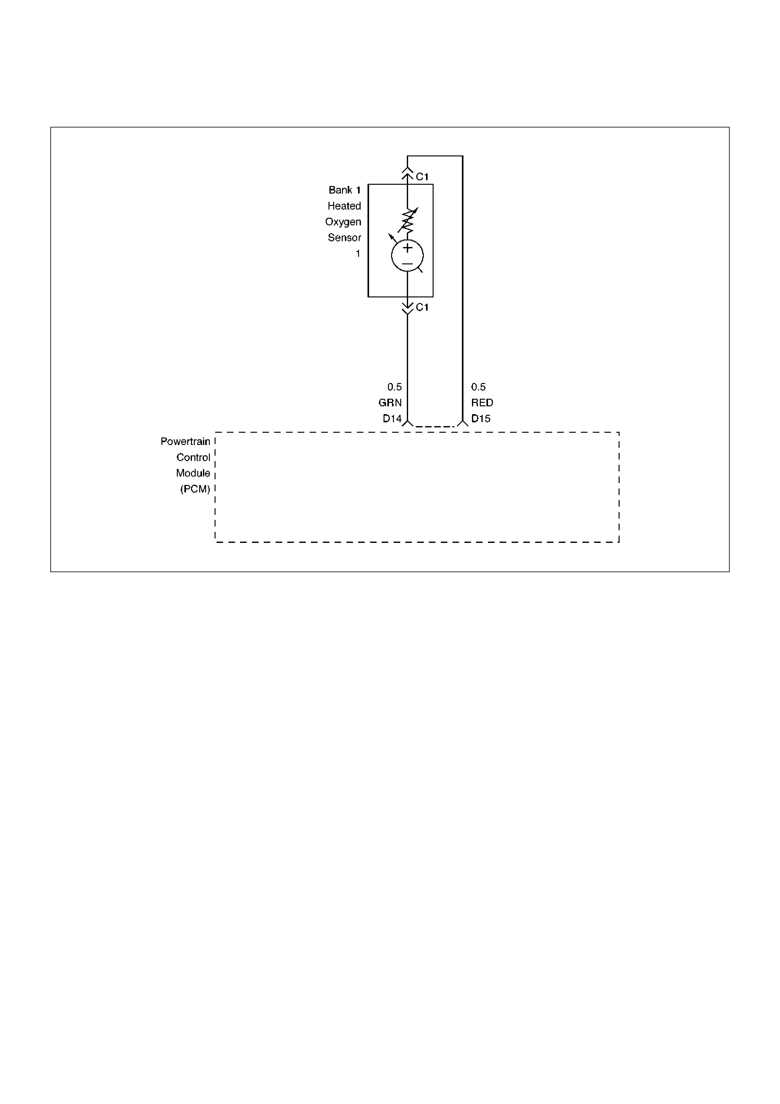
Diagnostic Trouble Code (DTC) P0132 HO2S Circuit High Voltage Bank 1 Sensor 1
060RW236
Circuit Description
The powertrain control module (PCM) supplies a bias
voltage of about 450 mV between the heated oxygen
sensor (HO2S) signal and low circuits. When measured
with a 10 megaohm digital voltmeter, this may display
as low as 320 mV. The oxygen sensor varies the
voltage within a range of about 1000 mV when exhaust
is rich, down through about 10 mV when exhaust is
lean. The PCM constantly monitors the HO2S signal
during “closed loop” operation and compensates for a
rich or lean condition by decreasing or increasing
injector pulse width as necessary. If the Bank 1 HO2S 1
voltage remains excessively high for an extended
period of time, DTC P0132 will be set.
Conditions for Setting the DTC
•No related DTCs.
•Engine coolant temperature is above 60°C (140°F)
•“Closed loop” commanded air/fuel ratio is between
14.5 and 14.8.
•Throttle angle is between 3% and 19%.
•Bank 1 HO2S 1 signal voltage remains above 952
mV during normal “closed loop” operation for a total
of 77 seconds over a 90-second period.
OR
•Bank 1 HO2S 1 signal voltage remains above 500
mV during “deceleration fuel cutoff mode” operation
for 3 seconds.
Action Taken When the DTC Sets
•The PCM will illuminate the malfunction indicator
lamp (MIL) the first time the fault is detected.
•The PCM will store conditions which were present
when the DTC was set as Freeze Frame and in the
Failure Records data.
•“Open loop” fuel control will be in effect.
Conditions for Clearing the MIL/DTC
•DTC P0132 can be cleared by using the Tech 2
“Clear Info” function or by disconnecting the PCM
battery feed.
Diagnostic Aids
Check the following items:
•Fuel pressure – The system will go rich if pressure is
too high. The PCM can compensate for some
increase. However, if fuel pressure is too high, a
DTC P0132 may be set. Refer to Fuel System
Diagnosis.
•Perform “Injector Balance Test” – Refer to Fuel
System Diagnosis.

•MAF sensor –The system can go rich if MAF sensor
signal indicates an engine airflow measurement that
is not correct. Disconnect the MAF sensor to see it
the rich condition is corrected. If so, replace the MAF
sensor.
•Check for a leak in the fuel pressure regulator
diaphragm by checking the vacuum line to the
regulator for the presence of fuel. There should be
no fuel in the vacuum line.
•An intermittent TP sensor output will cause the
system to go rich due to a false indication of the
engine accelerating.
•Shorted Heated Oxygen Sensor (HO2S) –If the
HO2S is internally shorted, the HO2S voltage
displayed on the Tech 2 will be over 1 volt. Try
disconnecting the affected HO2S with the key “ON,”
engine “OFF.” If the displayed HO2S voltage
changes from over 1000 mV to around 450 mV,
replace the HO2S. Silicon contamination of the
HO2S can also cause a high HO2S voltage to be
indicated. This condition is indicated by a powdery
white deposit on the portion of the HO2S exposed to
the exhaust stream. If contamination is noticed,
replace the affected HO2S.
•Open HO2S Signal Circuit or Faulty HO2S–A poor
connection or open in the HO2S signal circuit can
cause the DTC to set during deceleration fuel mode.
An HO2S which is faulty and not allowing a full
voltage swing between the rich and lean thresholds
can also cause this condition. Operate the vehicle by
monitoring the HO2S voltage with a Tech 2. If the
HO2S voltage is limited within a range between 300
mV to 600 mV, check the HO2S signal circuit wiring
and associated terminal conditions.
•If none of the above conditions are present, replace
the affected HO2S.
Test Description
Number(s) below refer to the step number(s) on the
Diagnostic Chart.
3. DTC P0132 failing during “deceleration fuel cutoff
mode” operation may indicate a condition described
in the “Diagnostic Aids” above. If the DTC P0132
test passes while the Failure Records conditions are
being duplicated, an intermittent condition is
indicated.
Reviewing the Failure Records vehicle mileage since
the diagnostic test last failed may help determine how
often the condition that caused the DTC to be set
occurs. This may assist in diagnosing the condition.
DTC P0132 – HO2S Circuit High Voltage Bank 1 Sensor 1
StepActionValue(s)YesNo
1 Was the “On-Board Diagnostic (OBD) System Check”
performed? — Go to Step 2
Go to OBD
System Check
2 1. Install the Tech 2.
2. Run the engine at operating temperature.
3. Operate the vehicle within parameters specified
under “Conditions for Setting the DTC” included in
Diagnostic Support.
4. Using a Tech 2, monitor Bank 1 HO2S 1 voltage.
Does the Bank 1 HO2S 1 voltage remain above the
specified value?
952 mV (500
mV in
deceleration
fuel cutoff
mode) Go to Step 4 Go to Step 3
3 1. Ignition “ON,” review and record Tech 2 Failure
Records data.
2. Operate the vehicle within Failure Records
conditions as noted.
3. Using a Tech 2, monitor “Specific DTC” info for
DTC P0132 until the DTC P0132 test runs.
4. Note the test result.
Does the Tech 2 indicate DTC P0132 failed this
ignition? — Go to Step 4
Refer to
Diagnostic Aids
4 1. Ignition “OFF.”
2. Disconnect Bank 1 HO2S 1.
3. Ignition “ON.”
4. At HO2S Bank 1 Sensor 1 connector (PCM side)
use a DVM to measure voltages at the high and
low signal terminals.
Are the voltages in the specified range? 3-4 V Go to Step 5 Go to Step 6

5 Repair short to voltage in signal circuit.
Is the action complete?—Verify repair—
6 1.Ignition “ON,” engine“OFF.”
2.At Bank 1 HO2S 1 connector (PCM side) jumper
both the HO2S high and low signal circuits (PCM
side) to ground.
3.Using a Tech 2, monitor Bank 1 HO2S 1 voltage.
Is Bank 1 HO2S 1 voltage below the specified value?10 mVGo to Step 7 Go to Step 8
7 1.Disconnect the jumpers to ground from Bank 1
HO2S 1 PCM-side connector.
2.With the HO2S 1 connector disconnected, monitor
Bank 1 HO2S 1 voltage.
Is Bank 1 HO2S 1 voltage between the specified
values?425-475 mV
Refer to
Diagnostic Aids Go to Step 8
8 Replace the PCM.
Important: The replacement PCM must be
programmed. Refer to Sections OC1 Service
Programming System and 11A1 6VE1 Immobiliser.
Is the action complete? — Verify repair —
Step Action Value(s) Yes No

Diagnostic Trouble Code (DTC) P0134 HO2S Circuit Insufficient Activity Bank 1 Sensor 1
060RW237
Circuit Description
• The powertrain control module (PCM) supplies a bias
voltage of about 450mV between the heated oxygen
sensor (HO2S) high and low circuits. When
measured with a 10 megaohm digital voltmeter, this
may display as low as 320mV. The oxygen sensor
varies the voltage within a range of about 1000mV
when the exhaust is rich, down through about 10mV
when exhaust is lean. The PCM constantly monitors
the HO2S signal during “closed loop” operation and
compensates for a rich or lean condition by
decreasing or increasing injector pulse width as
necessary. If the Bank 1 HO2S 1 voltage remains at
or near the 450mV bias for an extended period of
time, DTC P0134 will be set, indicating an open
sensor signal or sensor low circuit.
• Heated oxygen sensors are used to minimize the
amount of time required for “closed loop” fuel control
operation and to allow accurate catalyst monitoring.
The oxygen sensor heater greatly decreases the
amount of time required for fuel control sensors Bank
1 HO2S 1 and Bank 2 HO2S 1 to become active.
• Oxygen sensor heaters are required by post-catalyst
monitor sensors to maintain a sufficiently high
temperature for accurate exhaust oxygen content
readings further from the engine.
Conditions for Setting the DTC
• No related DTCs.
• Battery voltage is above 10 volts.
• Engine run time is longer than 40 seconds.
• Oxygen sensor heater has been determined to be
functioning properly.
• Bank 1 HO2S 1 signal voltage remains between
400mV and 500mV for a total of 77 seconds over a
90-second period of time.
Action Take When the DTC Sets
• The PCM will illuminate the malfunction indicator
lamp (MIL) the first time the fault is detected.
• The PCM will store conditions which were present
when the DTC was set as Freeze Frame and in the
Failure Records data.
• “Open loop” fuel control will be in effect.
Conditions for Clearing the MIL/DTC
• DTC P0134 can be cleared by using Tech 2 “Clear
Info” function or by disconnecting the PCM battery
feed.

Diagnostic Aids
Check for the following conditions:
•Poor connection or damaged harness – Inspect the
harness connectors for backed-out terminals,
improper mating, broken locks, improperly formed or
damaged terminals, poor terminal-to-wire connection,
and damaged harness.
•Faulty HO2S heater or heater circuit – With the
ignition “ON,” engine “OFF,” after a cool down period,
the HO2S 1 voltage displayed on Tech 2 is normally
455-460mV. A reading over 1000mV indicates a
signal line shorted to voltage. A reading under 5mV
indicates a signal line shorted to ground or signal
lines shorted together. Disconnect the HO2S and
connect a test light between the HO2S ignition feed
and heater ground circuits. If the test light does not
light for 2 seconds when the ignition is turned on,
repair the open ignition feed or sensor ground circuit
as necessary. If the test light lights and the HO2S
signal and low circuits are OK, replace the HO2S.
•Intermittent test – With the Ignition “ON,” monitor the
HO2S signal voltage while moving the wiring harness
and related connectors. If the fault is induced, the
HO2S signal voltage will change. This may help
isolate the location of the malfunction.
Test Description
Number(s) below refer to the step number(s) on the
Diagnostic Chart.
3. If the DTC P0134 test passes while the Failure
Records conditions are being duplicated, an
intermittent conditions is indicated.
Reviewing the Failure Records vehicle mileage since
the diagnostic test last failed may help determine how
often the condition that caused the DTC to be set
occurs. This may assist in diagnosing the condition.
DTC P0134 –HO2S Circuit Insufficient Activity Bank 1 Sensor 1
StepActionValue(s)YesNo
1 Was the “On-Board Diagnostic (OBD) System Check”
performed? — Go to Step 2
Go to OBD
System Check
2 1. Install Tech 2.
2. Run the engine at operating temperature.
3. Operate the engine above 1200 RPM for two
minutes.
Does Tech 2 indicate Bank 1 HO2S 1 voltage varying
outside the specified values? 400-500mV Go to Step 3 Go to Step 4
3 1. Ignition “ON,” engine “OFF,” review and record
Tech 2 Failure Records data and note parameters.
2. Operate the vehicle within Failure Records
conditions as noted.
3. Using Tech 2, monitor “Specific DTC” info for DTC
P0134 until the DTC P0134 test runs.
4. Note the test result.
Does Tech 2 indicate DTC P0134 failed this ignition? — Go to Step 4
Refer to
Diagnostic Aids
4 Check for a damaged harness.
Was a problem found? — Verify repair Go to Step 5
5 Check for poor Bank 1 HO2S 1 high and low circuit
terminal connections at the Bank 1 HO2S 1 harness
connector and replace terminal(s) if necessary.
Did any terminals require replacement? — Verify repair Go to Step 6
6 Check for poor Bank 1 HO2S 1 high and low circuit
terminal connections at the PCM and replace
terminals if necessary.
Did any terminals require replacement? — Verify repair Go to Step 7
7 1. Ignition “OFF.”
2. With the PCM disconnected, check continuity of
the Bank 1 HO2S 1 high circuit.
3. If the Bank 1 HO2S 1 high circuit measures over
5.0 ohms, repair open or poor connection as
necessary.
Was a Bank 1 HO2S 1 high circuit problem found and
corrected? — Verify repair Go to Step 8

8 1.Ignition “OFF.”
2.With the PCM disconnected, check continuity of
the Bank 1 HO2S 1 low circuit.
3.If the Bank 1 HO2S 1 low circuit measures over 5
ohms, repair open or poor connection as
necessary.
Was a Bank 1 HO2S 1 low circuit problem found and
corrected?—Verify repairGo to Step 9
9 1.Ignition “ON,” engine “OFF.”
2.Disconnect Bank 1 HO2S 1 and jumper the HO2S
high and low circuits (PCM side) to ground.
3.Using Tech 2, monitor Bank 1 HO2S 1 voltage.
Is Bank 1 HO2S 1 voltage in the specified range?0-10mVGo to Step 10 Go to Step 11
10 Replace Bank 1 HO2S 1.
Is the action complete?—Verify repair—
11 Replace the PCM.
Important: The replacement PCM must be
programmed. Refer to Sections OC1 Service
Programming System and 11A1 6VE1 Immobiliser.
Is the action complete? — Verify repair —
Step Action Value(s) Yes No
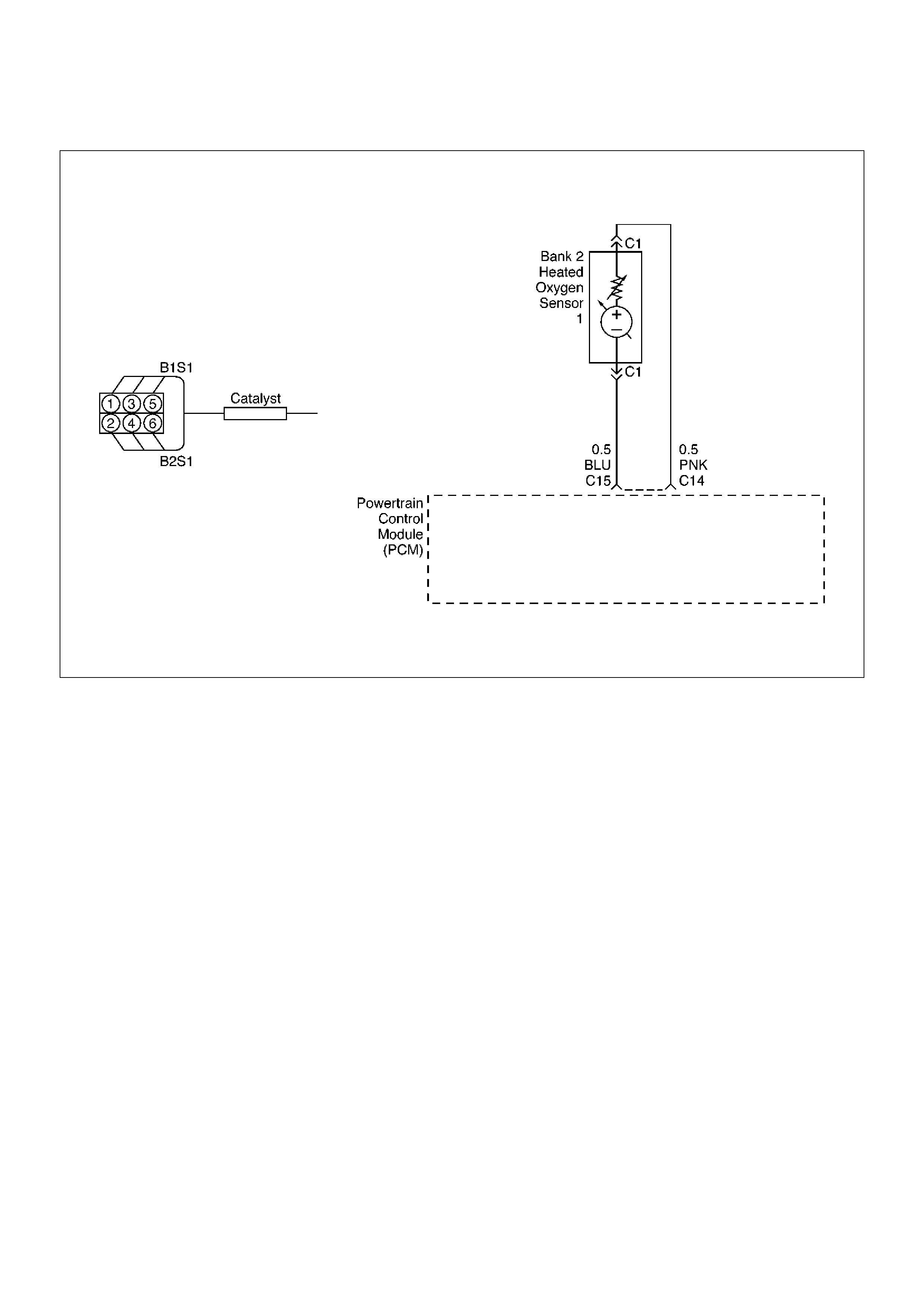
Diagnostic Trouble Code (DTC) P0151 HO2S Circuit Low Voltage Bank 2 Sensor 1
060RW190
Circuit Description
The powertrain control module (PCM) supplies a bias
voltage of about 450mV between the heated oxygen
sensor (HO2S) signal high and signal low circuits.
When measured with a 10 megaohm digital voltmeter,
this may display as low as 320mV. The oxygen sensor
varies the voltage within a range of about 1000mV
when the exhaust is rich, down through about 10mV
when exhaust is lean. The PCM constantly monitors
the HO2S signal during “closed loop” operation and
compensates for a rich or lean condition by decreasing
or increasing injector pulse width as necessary. If the
Bank 2 HO2S 1 voltage remains excessively low for an
extended period of time, DTC P0151 will be set.
Conditions for Setting the DTC
•No related DTCs.
•The engine is operating in “closed loop.”
•Engine coolant temperature is above 60°C (140°F).
•“Closed loop” commanded air/fuel ratio is between
14.5 and 14.8.
•Throttle angle is between 3% and 19%.
•Bank 2 HO2S 1 signal voltage remains below 22mV
during normal “closed loop” operation for a total of 77
seconds over a 90-second period of time.
Action Taken When the DTC Sets
•The PCM will illuminate the malfunction indicator
lamp (MIL) the first time the fault is detected.
•The PCM will store conditions which were present
when the DTC was set as Freeze Frame and in the
Failure Records data.
•“Open loop” fuel control will be in effect.
Conditions for Clearing the MIL/DTC
•DTC P0151 can be cleared by using Tech 2 “Clear
Info” function or by disconnecting the PCM battery
feed.
Diagnostic Aids
Check for the following conditions:
•Heated oxygen sensor wiring – The sensor pigtail
may be mispositioned and contacting the exhaust
system.
•Poor PCM to engine block grounds.
•Fuel pressure – The system will go lean if pressure is
too low. The PCM can compensate for some
decrease. However, if fuel pressure is too low, a DTC
P0151 may be set. Refer to Fuel System Diagnosis.
• Lean injector(s) – Perform “Injector Balance Test.”
• Vacuum leaks – Check for disconnected or damaged

vacuum hoses and for vacuum leaks at the intake
manifold, throttle body, EGR system, and PCV
system.
•Exhaust leaks – An exhaust leak may cause outside
air to be pulled into the exhaust gas stream past the
HO2S, causing the system to appear lean. Check for
exhaust leaks that may cause a false lean condition
to be indicated.
•MAF sensor –The system can go lean if the MAF
sensor signal indicates an engine airflow
measurement that is not correct. Disconnect the MAF
sensor to see if the lean condition is corrected. If so,
replace the MAF sensor.
•Fuel contamination – Water, even in small amounts,
can be delivered to the fuel injectors. The water can
cause a lean exhaust to be indicated. Excessive
alcohol in the fuel can also cause this condition.
Refer to Fuel System Diagnosis for the procedure to
check for fuel contamination.
•If none of the above conditions are present, replace
the affected HO2S.
Test Description
Number(s) below refer to the step number(s) on the
Diagnostic Chart.
3. DTC P0151 failing during operation may indicate a
condition described in the “Diagnostic Aids” above.
If the DTC P0151 test passes while the Failure
Records conditions are being duplicated, an
intermittent condition is indicate.
Reviewing the Failure Records vehicle mileage since
the diagnostic test last failed may help determine how
often the condition that caused the DTC to be set
occurs. This may assist in diagnosing the condition.
DTC P0151 – HO2S Circuit Low Voltage Bank 2 Sensor 1
StepActionValue(s)YesNo
1 Was the “On-Board Diagnostic (OBD) System Check”
performed? — Go to Step 2
Go to OBD
System Check
2 1. Install Tech 2.
2. Run the engine at operating temperature.
3. Operate the vehicle within the parameters
specified under “Conditions for Setting the DTC”
criteria included in Diagnostic Support.
4. Using Tech 2, monitor Bank 2 HO2S 1 voltage.
Does the Bank 2 HO2S 1 voltage remain below the
specified value? 22mV Go to Step 4 Go to Step 3
3 1. Ignition “ON,” engine “OFF,” review and record
Tech 2 Failure Records data and note parameters.
2. Operate the vehicle within Failure Records
conditions as noted.
3. Using Tech 2, monitor “Specific DTC” info for DTC
P0151 until the DTC P0151 test runs.
4. Note test result.
Does Tech 2 indicate DTC P0151 failed this ignition? — Go to Step 4
Refer to
Diagnostic Aids
4 1. Turn ignition “OFF.”
2. Disconnect the PCM.
3. Check the Bank 2 HO2S 1 high and low signal
circuits for a short to ground or a short to the
heater ground circuit.
Were Bank 2 HO2S 1 signal circuits shorted? — Go to Step 5 Go to Step 6
5 Repair the Bank 2 HO2S 1 signal circuit.
Is the action complete? — Verify repair —
6 1. Ignition “OFF.”
2. Leave the PCM and HO2S 1 disconnected.
3. Check for continuity between the high and low
signal circuits.
Was there continuity between the high and low
circuits? — Go to Step 7 Go to Step 8
7 Repair the short between the high and low circuits.
Is the action complete? — Verify repair —

8 1.Ignition “OFF.”
2.Reconnect the PCM, leave HO2S 2 disconnected.
3.Ignition “ON.”
Does Tech 2 indicate Bank 2 HO2S 1 voltage near the
specified value?425-475mV
Refer to
Diagnostic Aids Go to Step 9
9 Replace the PCM.
Important: The replacement PCM must be
programmed. Refer to Sections OC1 Service
Programming System and 11A1 6VE1 Immobiliser.
Is the action complete? — Verify repair —
Step Action Value(s) Yes No

Diagnostic Trouble Code (DTC) P0152 HO2S Circuit HIGH Voltage Bank 2 Sensor 1
060RW190
Circuit Description
The powertrain control module (PCM) supplies a bias
voltage of about 450mV between the heated oxygen
sensor (HO2S) signal high and signal low circuits.
When measured with a 10 megaohm digital voltmeter,
this may display as low as 320mV. The oxygen sensor
varies the voltage within a range of about 1000mV
when the exhaust is rich, down through about 10mV
when exhaust is lean. The PCM constantly monitors
the HO2S signal during “closed loop” operation and
compensates for a rich or lean condition by decreasing
or increasing the injector pulse width as necessary. If
the Bank 2 HO2S 1 voltage remains excessively high
for an extended period of time, DTC P0152 will be set.
Conditions for Setting the DTC
•No related DTCs.
•The engine is operating in “closed loop.”
•The engine coolant temperature is above 60°C
(140°F).
•“Closed loop” commanded air/fuel ratio between 14.5
and 14.8.
•Throttle angle between 3% and 19%.
•Bank 2 HO2S 1 signal voltage remains above 952mV
during normal “closed loop” operation for a total of 77
seconds over a 90-second period.
OR
•Bank 2 HO2S 1 signal voltage remains above 500mV
during deceleration fuel cutoff mode operation for up
to 3 seconds.
Action Taken When the DTC Sets
•The PCM will illuminate the malfunction indicator
lamp (MIL) the first time the fault is detected.
•The PCM will store conditions which were present
when the DTC was set as Freeze Frame and in the
Failure Records data.
•“Open loop” fuel control will be in effect.
Conditions for Clearing the MIL/DTC
•DTC P0152 can be cleared by using Tech 2 “Clear
Info” function or by disconnecting the PCM battery
feed.
Diagnostic Aids
Check for the following conditions:
•Fuel pressure – The system will go rich if pressure is
too high. The PCM can compensate for some
increase. However, if fuel pressure is too high, a
DTC P0152 may be set. Refer to Fuel System
Diagnosis.

•Rich injector(s) – Perform “Injector Balance Test.”
•Leaking injector – Refer to Fuel System Diagnosis.
•Evaporative emissions (EVAP) system – Check the
canister for fuel saturation. If the canister is full of
fuel, check EVAP control system components and
hoses. Refer to Evaporative Emission (EVAP)
Control System.
•MAF sensor – The system can go rich if the MAF
sensor signal indicates an engine airflow
measurement that is not correct. Disconnect the MAF
sensor to see if rich condition is corrected. If so,
replace MAF sensor.
•Check for leaking fuel pressure regulator diaphragm
by checking vacuum line to regulator for the presence
of fuel. There should be no fuel in the vacuum line.
•TP sensor – An intermittent TP sensor output will
cause the system to go rich, due to a false indication
of the engine accelerating.
•Shorted Heated Oxygen Sensor (HO2S)– If the
HO2S is internally shorted, the HO2S voltage
displayed on Tech 2 will be over 1 volt. Try
disconnecting the affected HO2S with the key “ON,”
engine “OFF.” If the displayed HO2S voltage
changes from over 1000mV to around 450mV,
replace the HO2S. Silicon contamination of the
HO2S can cause a high HO2S voltage to be
indicated. This condition is indicated by powdery
white deposit on the portion of the HO2S exposed to
the exhaust stream. If contamination is noticed,
replace the affected HO2S.
•Open HO2S Signal Circuit of Faulty HO2S– A poor
connection or open in the HO2S signal circuit can
cause the DTC to set during deceleration fuel mode.
An HO2S which is faulty and not allowing a full
voltage switch between the rich and lean thresholds
can also cause the condition. Operate the vehicle
while monitoring the HO2S voltage with Tech 2. If the
HO2S is limited within a range between 300mV to
600mV, check the HO2S signal circuit wiring and
associated terminal connections.
•If none of the above conditions are present, replace
the affected HO2S.
Test Description
Number(s) below refer to the step number(s) on the
Diagnostic Chart.
3. DTC P0152 failing during deceleration fuel cutoff
mode operation may indicate a condition described
in the “Diagnostic Aids” above. If the DTC P0152
test passes while the Failure Records conditions are
being duplicated, an intermittent condition is
indicated.
Reviewing the Failure Records vehicle mileage since
the diagnostic test last failed may help determine how
often the condition that caused the DTC to be set
occurs. This may assist in diagnosing the condition.
DTC P0152 – HO2S Circuit High Voltage Bank 2 Sensor 1
StepActionValue(s)YesNo
1 Was the “On-Board Diagnostic (OBD) System Check”
performed? — Go to Step 2
Go to OBD
System Check
2 1. Install Tech 2.
2. Engine is at operating temperature.
3. Operate the vehicle within the parameters
specified under “Conditions for Setting the DTC”
criteria included in Diagnostic Support.
4. Using Tech 2, monitor Bank 2 HO2S 1 voltage.
Does the Bank 2 HO2S 1 voltage remain above the
specified value?
952mV
(500mV in
deceleration
fuel cut-off
mode) Go to Step 4 Go to Step 3
3 1. Ignition “ON.”
2. Review and record Tech 2 Failure Records data.
3. Operate the vehicle within Failure Records
conditions as noted.
4. Using Tech 2, monitor “Specific DTC” info for DTC
P0152 until the DTC P0152 test runs.
5. Note the test result.
Does Tech 2 indicate DTC P0152 failed this ignition? — Go to Step 4
Refer to
Diagnostic Aids

4 1.Ignition “OFF.”
2.Disconnect Bank 2 HO2S 1.
3.Ignition “ON.”
4.At HO2S Bank 2 Sensor 1 connector (PCM side)
use a DVM to measure voltages at the high and
low signal terminals.
Are the voltages in the specified range?3-4 VGo to Step 5 Go to Step 6
5 Repair short to voltage in signal circuit.
Is the action complete?—Verify repair—
6 1.Ignition “ON,” engine“OFF.”
2.At Bank 2 HO2S 1 connector (PCM side) jumper
both the HO2S high and low signal circuits (PCM
side) to ground.
3.Using Tech 2, monitor Bank 2 HO2S 1 voltage.
Is Bank 2 HO2S 1 voltage below the specified value?10mVGo to Step 7 Go to Step 8
7 1.Disconnect the jumpers to ground from Bank 2
HO2S 1 PCM-side connector.
2.With the HO2S 1 connector disconnected,
monitor Bank 2 HO2S 1 voltage.
Is the Bank 2 HO2S 1 voltage between the specified
values?425-475mV
Refer to
Diagnostic Aids Go to Step 8
8 Replace the PCM.
Important: The replacement PCM must be
programmed. Refer to Sections OC1 Service
Programming System and 11A1 6VE1 Immobiliser.
Is the action complete? — Verify repair —
Step Action Value(s) Yes No
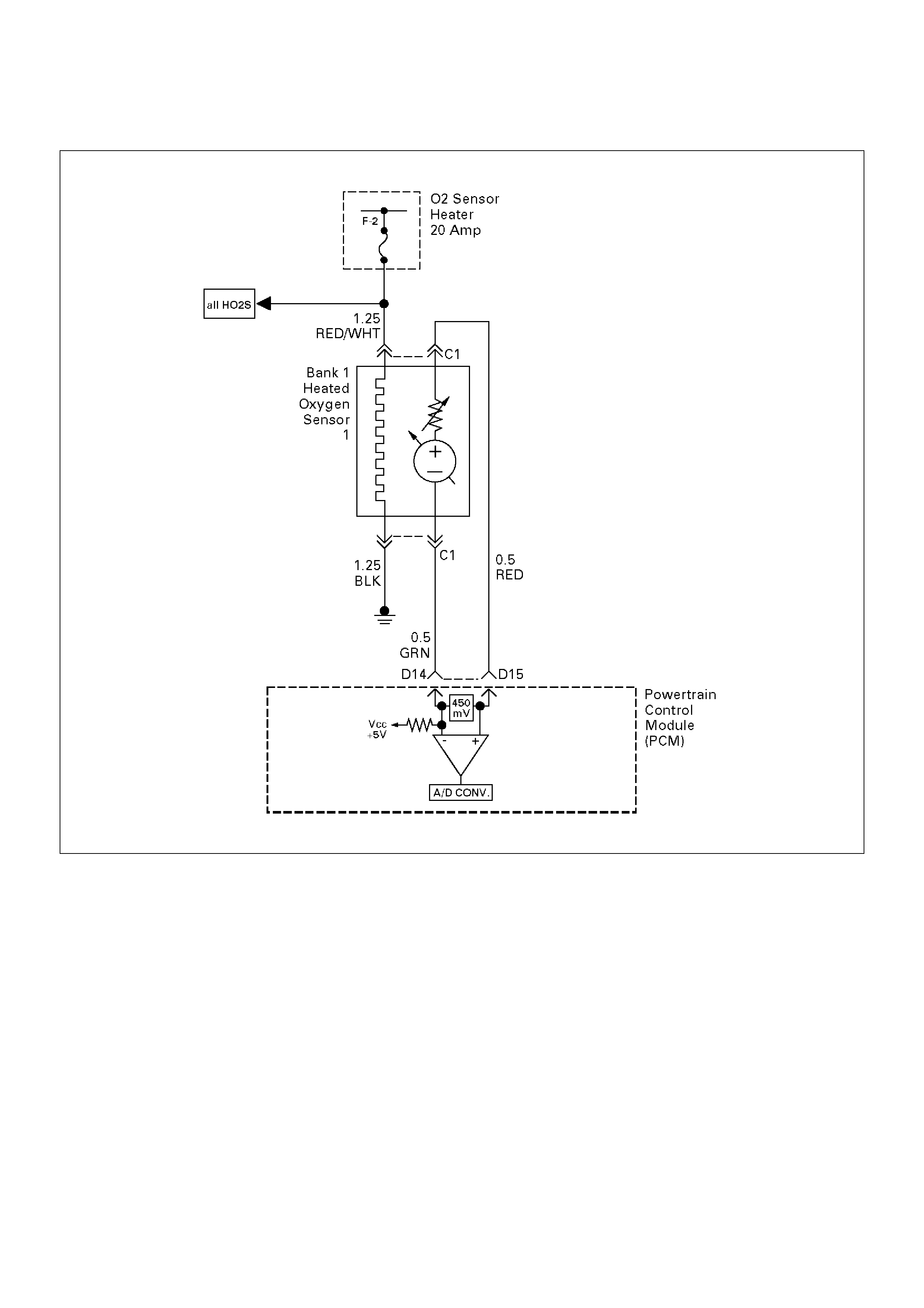
Diagnostic Trouble Code (DTC) P0171 Fuel Trim System Lean Bank 1
D06RW030
Circuit Description
To provide the best possible combination of driveability,
fuel economy, and emission control, a “closed loop” air/
fuel metering system is used. While in “closed loop,”
the powertrain control module (PCM) monitors the Bank
1 HO2S 1 and Bank 2 HO2S 1 signals and adjusts fuel
delivery based upon the HO2S signal voltages. A
change made to fuel delivery will be indicated by the
long and short term fuel trim values which can be
monitored with a Tech 2. Ideal fuel trim values are
around 0%; if the HO2S signals are indicating a lean
condition the PCM will add fuel, resulting in fuel trim
values above 0%. If a rich condition is detected, the
fuel trim values will be below 0%, indicating that the
PCM is reducing the amount of fuel delivered. If an
excessively lean condition is detected on Bank 1, the
PCM will set DTC P0171.
The PCM's maximum authority to control long term fuel
trim allows a range between –15% (automatic
transmission) or –12% (manual transmission) and
+20%. The PCM monitors fuel trim under various
engine speed/load fuel trim cells before determining the
status of the fuel trim diagnostic.
Conditions for Setting the DTC
• No Tech 2 test is being run.
• None of the following: EGR DTCs, HO2S DTCs,
(response, transition, open, low volts, no activity),
MAF DTCs, TP sensor DTCs, MAP DTCs, IAT DTCs,
canister purge DTCs, EVAP DTCs, injector circuit
DTCs, or misfire DTCs.
• Engine coolant temperature is between 25°C (77°F)
and 100°C (212°F).
• Intake air temperature is between –40°C (–40°F) and
120°C (248°F).

•Manifold absolute pressure is between 24 kPa and
99 kPa.
•Throttle angle is steady below 95%.
•Vehicle speed is below 136 km/h (85 mph).
•Engine speed is between 400 and 6,000 RPM.
•Barometric pressure is greater than 72.5 kPa.
•Mass air flow is between 2 g/second and 200 g/
second.
•Ignition voltage is above 9.5 volts.
•Fuel system is in “closed loop.”
Action Taken When the DTC Sets
•The PCM will illuminate the malfunction indicator
lamp (MIL) after the second consecutive trip in which
the fault is detected.
•The PCM will store conditions which were present
when the DTC was set as Freeze Frame and in the
Failure Records data.
Conditions for Clearing the MIL/DTC
•DTC P0171 can be cleared by using the Tech 2
“Clear Info” function or by disconnecting the PCM
battery feed.
Diagnostic Aids
Check for the following conditions:
•Poor connection at PCM – Inspect harness
connectors for backed-out terminals, improper
mating, broken locks, improperly formed or damaged
terminals, and poor terminal-to-wire connection.
•Damaged harness – Inspect the wiring harness for
damage. If the harness appears to be OK, observe
the Bank 1 HO2S 1 display on the Tech 2 while
moving connectors and wiring harnesses related to
the engine harness. A change in the display will
indicate the location of the fault.
Reviewing the Failure Records vehicle mileage since
the diagnostic test last failed may help determine how
often the condition that caused the DTC to be set
occurs. This may assist in diagnosing the condition.
Test Description
Number(s) below refer to the step number(s) on the
Diagnostic Chart.
2. DTCs other than P0171 and P0174 may indicate a
condition present which may cause a lean condition.
If this is the case, repairing the condition which
caused the other DTC will most likely correct the
DTC P0171/P0174.
4. If the DTC P0171 test passes while the Failure
Records conditions are being duplicated, the lean
condition is intermittent. Refer to Diagnostic Aids or
Symptoms for additional information on diagnosing
intermittent problems.
DTC P0171 – Fuel Trim System Lean Bank 1
StepActionValue(s)YesNo
1 Was the “On-Board Diagnostic (OBD) System Check”
performed? — Go to Step 2
Go to OBD
System Check
2 Are any DTCs set other than P0171 and P0174?
—
Go to the
applicable DTC
charts and
repair the other
DTCs before
proceeding with
this chart Go to Step 3
3 1. Start the engine and operate the vehicle in “closed
loop.”
2. Observe the “BANK 1 L.T. FUEL TRIM” display
on the Tech 2.
Is the displayed value greater than the specified
value?
L.T. Fuel
Trim: +20% Go to Step 5 Go to Step 4

4 1. Review and record the Tech 2 Failure Records
data.
2. Clear the DTC P0171/P0174 and operate the
vehicle to duplicate the Failure Records
conditions.
3. Monitor the Tech 2 “Specific DTC” info for DTC
P0171 while operating the vehicle to duplicate the
Failure Records conditions.
4. Continue operating the vehicle until the DTC
P0171 test runs and note the test result.
Does the Tech 2 indicate DTC P0171 failed this
ignition? — Go to Step 5
The lean
condition is not
present. If a
driveability
symptom still
exists, refer to
Symptoms
section.
5 Was DTC P0174 also set? — Go to Step 6 Go to Step 15
6 Visually and physically inspect the vacuum hoses for
disconnects, splits, kinks, improper routing and
improper connections and repair any problem found.
Did your inspection reveal a problem requiring repair? — Verify repair Go to Step 7
7 Visually and physically inspect the crankcase
ventilation valve for proper installation and repair any
problem found (refer to Crankcase Ventilation
System).
Did your inspection reveal a problem requiring repair? — Verify repair Go to Step 8
8 1. Inspect the MAF sensor inlet screen for damage
or for the presence of foreign objects which may
partially block the air flow sample through the MAF
sensor.
2. Correct any problem that is found as necessary.
Did your inspection of the MAF sensor reveal a
condition requiring repair? — Verify repair Go to Step 9
9 Start the engine and note the idle quality.
Is a high or unsteady idle being experienced? — Go to Step 10 Go to Step11
10 1. Visually and physically inspect the throttle body,
intake manifold, EGR valve and the EGR feed
pipe for vacuum leaks.
2. Repair any vacuum leaks as necessary.
Did your inspection reveal a vacuum leak? — Verify repair Go to Step 11
11 Check the fuel for excessive water, alcohol, or other
contaminants (see Diagnosis in Engine Fuel for the
procedure) and correct the contaminated fuel
condition if present (see Engine Fuel).
Was the fuel contaminated? — Verify repair Go to Step 12
12 1. Visually and physically inspect the PCM injector
grounds, power grounds and sensor grounds to
ensure that they are clean, tight, and in their
proper locations.
2. If a faulty ground condition is present, correct it as
necessary.
Did your inspection reveal a condition requiring
repair? — Verify repair Go to Step 13
Step Action Value(s) Yes No

13 1. Disconnect the MAF sensor electrical connector.
2. Operate the vehicle in “closed loop” while
monitoring the “BANK 1 S.T. FUEL TRIM”
displayed on the Tech 2.
Does “BANK 1 S.T. FUEL TRIM” value decrease to
near the specified value? 0% Go to Step 19 Go to Step 14
14 Perform the procedure in the “Fuel System Pressure
Test” and repair fuel system problem if necessary.
Did Fuel System Pressure Test isolate a condition
requiring repair? — Verify repair Go to Step 15
15 1. Visually and physically inspect the intake
manifold, injector O-rings, EGR adapter, EGR
valve and the EGR feed pipes for vacuum leaks.
2. Repair any problem that is found.
Did your inspection reveal a problem? — Verify repair Go to Step 16
16 Visually and physically inspect the Bank 1 exhaust
manifold for leaks and loose or missing hardware and
correct any problem found.
Did your inspection reveal a problem? — Verify repair Go to Step 17
17 Perform the “Injector Balance Test,” and correct any
problem found (refer to Fuel Metering System).
Did Injector Balance Test isolate a problem? — Verify repair Go to Step 18
18 1. Visually and physically inspect the Bank 1 HO2S 1
to ensure that it is installed securely and that the
Bank 1 HO2S 1 pigtail and wiring harness are not
contacting the exhaust or otherwise damaged.
2. If a problem is found, correct it as necessary.
Did your inspection reveal a problem? — Verify repair
Refer to
Diagnostic Aids
19 Replace the MAF sensor.
Is the action complete? — Verify repair —
Step Action Value(s) Yes No
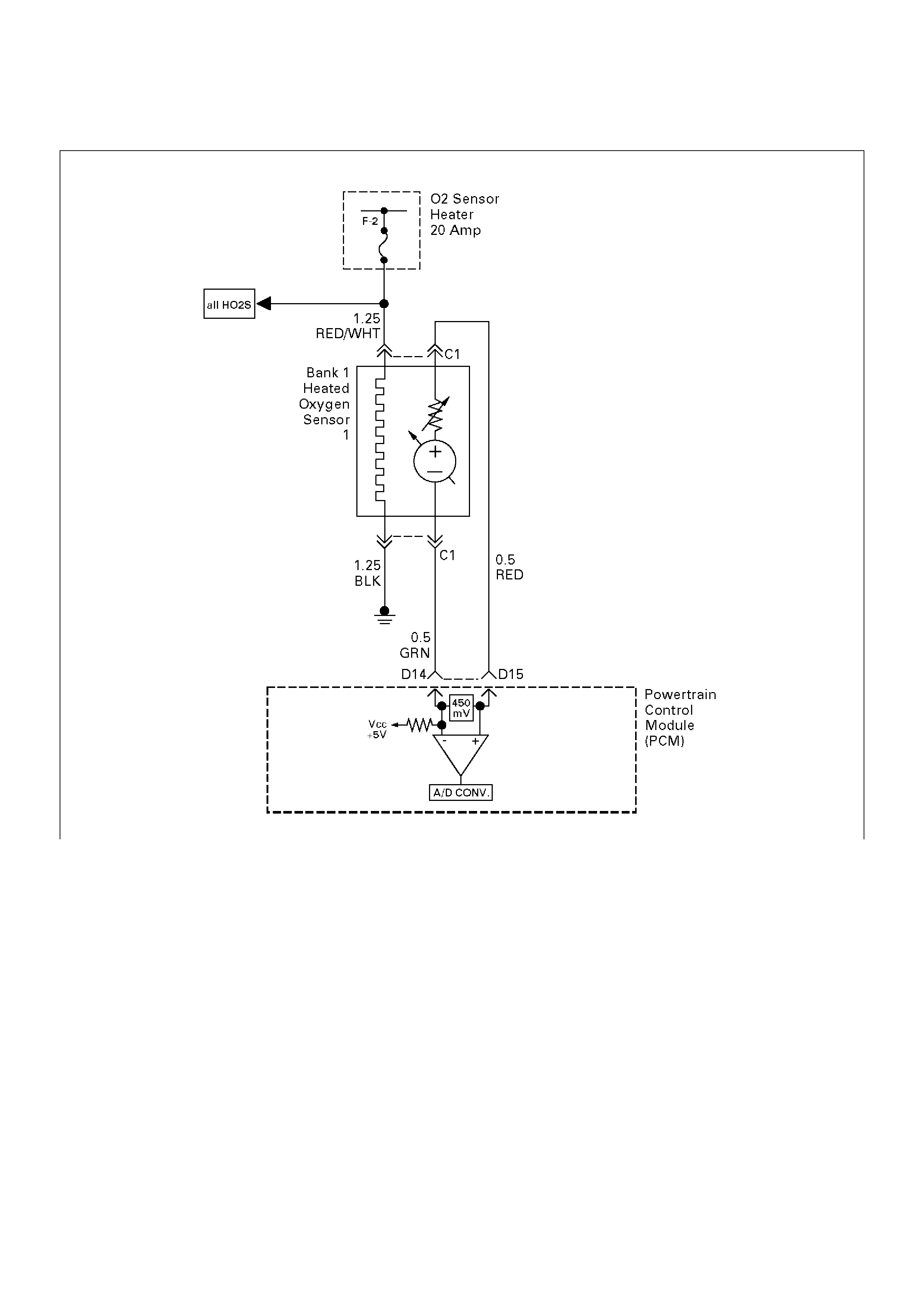
Diagnostic Trouble Code (DTC) P0172 Fuel Trim System Rich Bank 1
D06RW030
Circuit Description
To provide the best possible combination of driveability,
fuel economy, and emission control, a “closed loop” air/
fuel metering system is used. While in “closed loop,”
the powertrain control module (PCM) monitors the Bank
1 heated oxygen sensors (HO2S) 1 and Bank 2 HO2S 1
signals and adjusts fuel delivery based upon the HO2S
signal voltages. A change made to fuel delivery will be
indicated by the long and short term fuel trim values
which can be monitored with a Tech 2. Ideal fuel trim
values are around 0%; if the HO2S signals are
indicating a lean condition the PCM will add fuel,
resulting in fuel trim values above 0%. If a rich condition
is detected, the fuel trim values will be below 0%,
indicating that the PCM is reducing the amount of fuel
delivered. If an excessively rich condition is detected on
Bank 1, the PCM will set DTC P0172.
The PCM's maximum authority to control long term fuel
trim allows a range between –15% (automatic
transmission) or –12 (manual transmission) and +20%.
The PCM's maximum authority to control short term fuel
trim allows a range between –11% and +20%. The
PCM monitors fuel trim under various engine speed/
load fuel trim cells before determining the status of the
fuel trim diagnostic.
Conditions for Setting the DTC
• No Tech 2 test is being run.
• None of the following was set: EGR DTCs, HO2S
DTCs, (response, transition, open, low volts, no
activity), MAF DTCs, TPS DTCs, MAP DTCs, IAT
DTCs, canister purge DTCs, EVAP DTCs, injector
circuit DTCs, or misfire DTCs.
• Engine coolant temperature is between 25°C (77°F)
and 100°C (212°F).
• Intake air temperature is between –40°C (–40°F) and
120°C (248°F).

•Manifold absolute pressure is between 24 kPa and
99 kPa.
•Throttle angle is steady below 95%.
•Vehicle speed is below 136 km/h (85 mph).
•Engine speed is between 400 and 6,000 RPM.
•Barometric pressure is greater than 72.5 kPa.
•Mass air flow is between 2 g/second and 200 g/
second.
•Ignition voltage is above 9.5 volts.
•Fuel system is in “closed loop.”
Action Taken When the DTC Sets
•The PCM will illuminate the malfunction indicator
lamp (MIL) after the second consecutive trip in which
the fault is detected.
•The PCM will store conditions which were present
when the DTC was set as Freeze Frame and in the
Failure Records data.
Conditions for Clearing the MIL/DTC
•DTC P0172 can be cleared by using the Tech 2
“Clear Info” function or by disconnecting the PCM
battery feed.
Diagnostic Aids
Check for the following conditions:
•Poor connection at PCM – Inspect harness
connectors for backed-out terminals, improper
mating, broken locks, improperly formed or damaged
terminals, and poor terminal-to-wire connection.
•Damaged harness – Inspect the wiring harness for
damage. If the harness appears to be OK, observe
the Bank 1 HO2S 1 display on the Tech 2 while
moving connectors and wiring harnesses related to
the engine harness. A change in the display will
indicate the location of the fault.
Reviewing the Failure Records vehicle mileage since
the diagnostic test last failed may help determine how
often the condition that caused the DTC to be set
occurs. This may assist in diagnosing the condition.
Test Description
Number(s) below refer to the step number(s) on the
Diagnostic Chart.
2. DTCs other than P0172 and P0175 may indicate a
condition present which may cause a lean condition.
If this is the case, repairing the condition which
caused the other DTC will most likely correct the
DTC P0172/P0175.
4. If the DTC P0172 test passes while the Failure
Records conditions are being duplicated, the rich
condition is intermittent. Refer to Diagnostic Aids or
Symptoms for additional information on diagnosing
intermittent problems.

DTC P0172 – Fuel Trim System Rich Bank 1
StepActionValue(s)YesNo
1 Was the “On-Board Diagnostic (OBD) System Check”
performed? — Go to Step 2
Go to OBD
System Check
2 Are any DTCs set other than P0172 and P0175?
—
Go to the
applicable DTC
charts and
repair the other
DTCs before
proceeding with
this chart Go to Step 3
3 1. Start the engine and operate the vehicle in “closed
loop.”
2. Observe “B1 Long Term Fuel Trim” display on the
Tech 2.
Is the displayed value more negative than the
specified value?
L.T. Fuel
Trim: –15%
(auto. trans.)
OR –12%
(man. trans.) Go to Step 5 Go to Step 4
4 1. Review and record the Tech 2 Failure Records
data.
2. Clear the DTC P0172/P0175 and operate the
vehicle to duplicate the Failure Records
conditions.
3. Monitor the Tech 2 “DTC” info for DTC P0172
while operating the vehicle to duplicate the Failure
Records conditions.
4. Continue operating the vehicle until the DTC
P0172 test runs and note test result.
Does the Tech 2 indicate DTC P0172 failed this
ignition? — Go to Step 5
The rich
condition is not
present. If a
driveability
symptom still
exists, refer to
Symptoms.
5 Is DTC P0175 also set? — Go to Step 6 Go to Step 15
6 Visually and physically inspect the air filter element
and replace it if necessary.
Did the air filter require replacement? — Verify repair Go to Step 7
7 Visually and physically inspect the air intake duct for
collapse or restriction and repair if necessary.
Did your inspection reveal a condition requiring
repair? — Verify repair Go to Step 8
8 Inspect the MAF sensor inlet screen for damage or for
the presence of foreign objects which may partially
block air flow through the screen and correct any
problem found.
Did your inspection of the MAF sensor reveal a
condition requiring repair or replacement? — Verify repair Go to Step 9
9 Start the engine and note the idle quality.
Is a low or unsteady idle being experienced? — Go to Step 10 Go to Step 11
10 1. Ignition “OFF.”
2. Physically inspect the throttle body bore, throttle
plate, and IAC passages for coking and foreign
objects.
3. If a problem was found, repair as necessary.
Did your inspection reveal a condition requiring
repair? — Verify repair Go to Step 11

11 1.Disconnect the vacuum hose from the fuel
pressure regulator and inspect the hose for the
presence of fuel.
2.If fuel is present in the vacuum hose, replace the
fuel pressure regulator (refer to Fuel Metering
System).
Did the fuel pressure regulator require replacement?—Verify repairGo to Step 12
12 Ignition “ON,” engine “OFF,” monitor the TP Angle
display on the Tech 2 while slowly depressing the
accelerator pedal.
Does the TP Angle display increase steadily and
evenly from minimum value at closed throttle to
maximum value at wide-open throttle?
Minimum 0%
Maximum
100%Go to Step 13 Go to Step 18
13 1.Disconnect the MAF sensor electrical connector.
2.Operate the vehicle in “closed loop” while
monitoring the “BANK 1 L.T. FUEL TRIM” and
“BANK 1 S. T. FUEL TRIM” display on the Tech 2.
Did both values change to near the specified value?0%Go to Step 19 Go to Step 14
14 1.Perform “Fuel System Pressure Test.”
2.If Fuel System Pressure Test isolates a problem,
repair as necessary (refer to Engine Fuel or Fuel
Metering System).
Did the Fuel System Pressure Test isolate a problem
requiring repair?—Verify repairGo to Step 16
15 Replace the PCM.
Important: The replacement PCM must be
programmed. Refer to Sections OC1 Service
Programming System and 11A1 6VE1 Immobiliser.
Is the action complete? — Verify repair —
16 1. Perform the “Injector Balance Test.”
2. If Injector Balance Test isolates a problem, repair
as necessary (refer to Fuel Metering System).
Did the Injector Balance Test isolate a problem
requiring repair? — Verify repair Go to Step 17
17 1. Remove and visually/physically inspect the Bank
1 HO2S 1 for silicon contamination. This will be
indicated by a powdery white deposit on the
portion of the HO2S that is exposed to the
exhaust stream.
2. If contamination is evident on the Bank 1 HO2S 1,
replace the contaminated sensors.
Did the sensor require replacement? — Verify repair
Refer to
Diagnostic Aids
18 1. Check the TP sensor mounting screws and tighten
or replace them as necessary if they are loose or
missing.
2. If the screws are OK, replace the TP sensor.
Is the action complete? — Verify repair —
19 Replace the MAF sensor.
Is the action complete? — Verify repair —
Step Action Value(s) Yes No

Diagnostic Trouble Code (DTC) P0174 Fuel Trim System Lean Bank 2
D06RW031
Circuit Description
To provide the best possible combination of driveability,
fuel economy, and emission control, a “closed loop” air/
fuel metering system is used. While in “closed loop,”
the powertrain control module (PCM) monitors the Bank
1 HO2S 1 and Bank 2 HO2S 1 signals and adjusts fuel
delivery based upon the HO2S signal voltages. A
change made to fuel delivery will be indicated by the
long and short term fuel trim values which can be
monitored with a Tech 2. Ideal fuel trim values are
around 0%; if the HO2S signals are indicating a lean
condition the PCM will add fuel, resulting in fuel trim
values above 0%. If a rich condition is detected, the fuel
trim values will be below 0%, indicating that the PCM is
reducing the amount of fuel delivered. If an excessively
lean condition is detected on Bank 2, the PCM will set
DTC P0174.
The PCM's maximum authority to control long term fuel
trim allows a range between –15%(automatic
transmission) or –12%(manual transmission) and
+20%. The PCM monitors fuel trim under various
engine speed/load fuel trim cells before determining the
status of the fuel trim diagnostic.
Conditions for Setting the DTC
• No Tech 2 test is being run.
• None of the following DTCs are set: idle system,
EGR, HO2S, (response, transition, open, low volts,
no activity), MAF, TP sensor, MAP, IAT, canister
purge, EVAP, injector circuit, or misfire.
• Engine coolant temperature is between 25°C (77°F)
and 100°C (212°F).
• Intake air temperature is between –40°C (–40°F) and
120°C (248°F).

•Manifold absolute pressure is between 24 kPa and
99 kPa.
•Throttle angle is steady below 95%.
•Vehicle speed is below 136 km/h (85 mph).
•Engine speed is between 400 and 6,000 RPM.
•Barometric pressure is greater than 72.5 kPa.
•Mass air flow is between 2 g/second and 200 g/
second.
•Ignition voltage is above 9.5 volts.
•Fuel system is in “closed loop.”
Action Taken When the DTC Sets
•The PCM will illuminate the malfunction indicator
lamp (MIL) after the second consecutive trip in which
the failure is detected.
•The PCM will store conditions which were present
when the DTC was set as Freeze Frame and in the
Failure Records data.
Conditions for Clearing the MIL/DTC
•DTC P0174 can be cleared by using the Tech 2
“Clear Info” function or by disconnecting the PCM
battery feed.
Diagnostic Aids
Check for the following conditions:
•Poor connection at PCM – Inspect harness
connectors for backed-out terminals, improper
mating, broken locks, improperly formed or damaged
terminals, and poor terminal-to-wire connection.
•Damaged harness – Inspect the wiring harness for
damage. If the harness appears to be OK, observe
the Bank 2 HO2S 1 display on the Tech 2 while
moving connectors and wiring harnesses related to
the engine harness. A change in the display will
indicate the location of the fault.
Reviewing the Failure Records vehicle mileage since
the diagnostic test last failed may help determine how
often the condition that caused the DTC to be set
occurs. This may assist in diagnosing the condition.
Test Description
Number(s) below refer to the step number(s) on the
Diagnostic Chart.
2. DTCs other than P0171 and P0174 may indicate a
condition present which may cause a lean condition.
If this is the case, repairing the condition which
caused the other DTC will most likely correct the
DTC P0171/P0174.
4. If the DTC P0174 test passes while the Failure
Records conditions are being duplicated, the lean
condition is intermittent. Refer to Diagnostic Aids or
Symptoms for additional information on diagnosing
intermittent problems.

DTC P0174 – Fuel Trim System Lean Bank 2
StepActionValue(s)YesNo
1 Was the “On-Board Diagnostic (OBD) System Check”
performed? — Go to Step 2
Go to OBD
System Check
2 Are any DTCs set other than P0174 and P0171?
—
Go to the
applicable DTC
charts and
repair the other
DTCs before
proceeding with
this chart. Go to Step 3
3 1. Start the engine and operate the vehicle in “closed
loop.”
2. Observe the “BANK 2 L.T. FUEL TRIM” display on
the Tech 2.
Is the displayed values greater than the specified
values?
L.T. Fuel
Trim: +20% Go to Step 5 Go to Step 4
4 1. Review and record Tech 2 Failure Records data.
2. Clear the DTC P0171/P0174 and operate the
vehicle to duplicate the Failure Records
conditions.
3. Monitor the Tech 2 “DTC” info for DTC P0174
while operating the vehicle to duplicate the Failure
Records conditions.
4. Continue operating the vehicle until the DTC
P0174 test runs.
5. Note the test result.
Does the Tech 2 indicate DTC P0174 failed this
ignition? — Go to Step 5
The lean
condition is not
present. If a
driveability
symptom still
exists, refer to
Symptoms
section.
5 Was DTC P0171 also set? — Go to Step 6 Go to Step 15
6 Visually and physically inspect the vacuum hoses for
disconnects, splits, kinks, improper routing and
improper connections and repair any problem found.
Did your inspection reveal a problem requiring repair? — Verify repair Go to Step 7
7 Visually and physically inspect the crankcase
ventilation valve for proper installation and repair any
problem found (refer to Crankcase Ventilation
System).
Did your inspection reveal a problem requiring repair? — Verify repair Go to Step 8
8 1. Inspect the MAF sensor inlet screen for damage
or for the presence of foreign objects which may
partially block the air flow sample through the MAF
sensor.
2. Correct any problem that is found as necessary.
Did your inspection of the MAF sensor reveal a
condition requiring repair? — Verify repair Go to Step 9
9 Start the engine and note the idle quality.
Is a high or unsteady idle being experienced? — Go to Step 10 Go to Step 11
10 1. Visually and physically inspect the throttle body,
intake manifold, EGR valve and the EGR feed
pipe for vacuum leaks.
2. Repair any vacuum leaks as necessary.
Did your inspection reveal a vacuum leak? — Verify repair Go to Step 11

11 Check the fuel for excessive water, alcohol, or other
contaminants (see Diagnosis in Engine Fuel for
procedure) and correct the contaminated fuel
condition is present (see Engine Fuel).
Was the fuel contaminated? — Verify repair Go to Step 12
12 1. Visually and physically inspect the PCM injector
grounds, power grounds and sensor grounds to
ensure that they are clean, tight, and in their
proper locations.
2. If a faulty ground condition is present, correct it as
necessary.
Did your inspection reveal a condition requiring
repair? — Verify repair Go to Step 13
13 1. Disconnect the MAF sensor electrical connector.
2. Operate the vehicle in “closed loop” while
monitoring the “BANK 1 S.T. FUEL TRIM”
displayed on the Tech 2.
Does the “BANK 1 S.T. FUEL TRIM” value decrease
to near the specified value? 0% Go to Step 19 Go to Step 14
14 Perform the procedure in the "Fuel System Pressure
Test" and repair fuel system problem if necessary.
Did the Fuel System Pressure Test isolate a condition
requiring repair? — Verify repair Go to Step 15
15 1. Visually and physically inspect the intake
manifold, injector O-rings, EGR adapter, EGR
valve and the EGR feed pipes for vacuum leaks.
2. Repair any problem that is found.
Did your inspection reveal a problem? — Verify repair Go to Step 16
16 Visually and physically inspect the Bank 2 exhaust
manifold for leaks and loose or missing hardware and
correct any problem found.
Did your inspection reveal a problem? — Verify repair Go to Step 17
17 Perform the “Injector Balance Test,” and correct any
problem found (refer to Fuel Metering System).
Did the Injector Balance Test isolate a problem? — Verify repair Go to Step 18
18 1. Visually and physically inspect the Bank 2 HO2S 1
to ensure that it is installed securely and that the
Bank 2 HO2S 1 pigtail and wiring harness are not
contacting the exhaust or otherwise damaged.
2. If a problem is found, correct it as necessary.
Did your inspection reveal a problem? — Verify repair
Refer to
Diagnostic Aids
19 Replace the MAF sensor.
Is the action complete? — Verify repair —
Step Action Value(s) Yes No
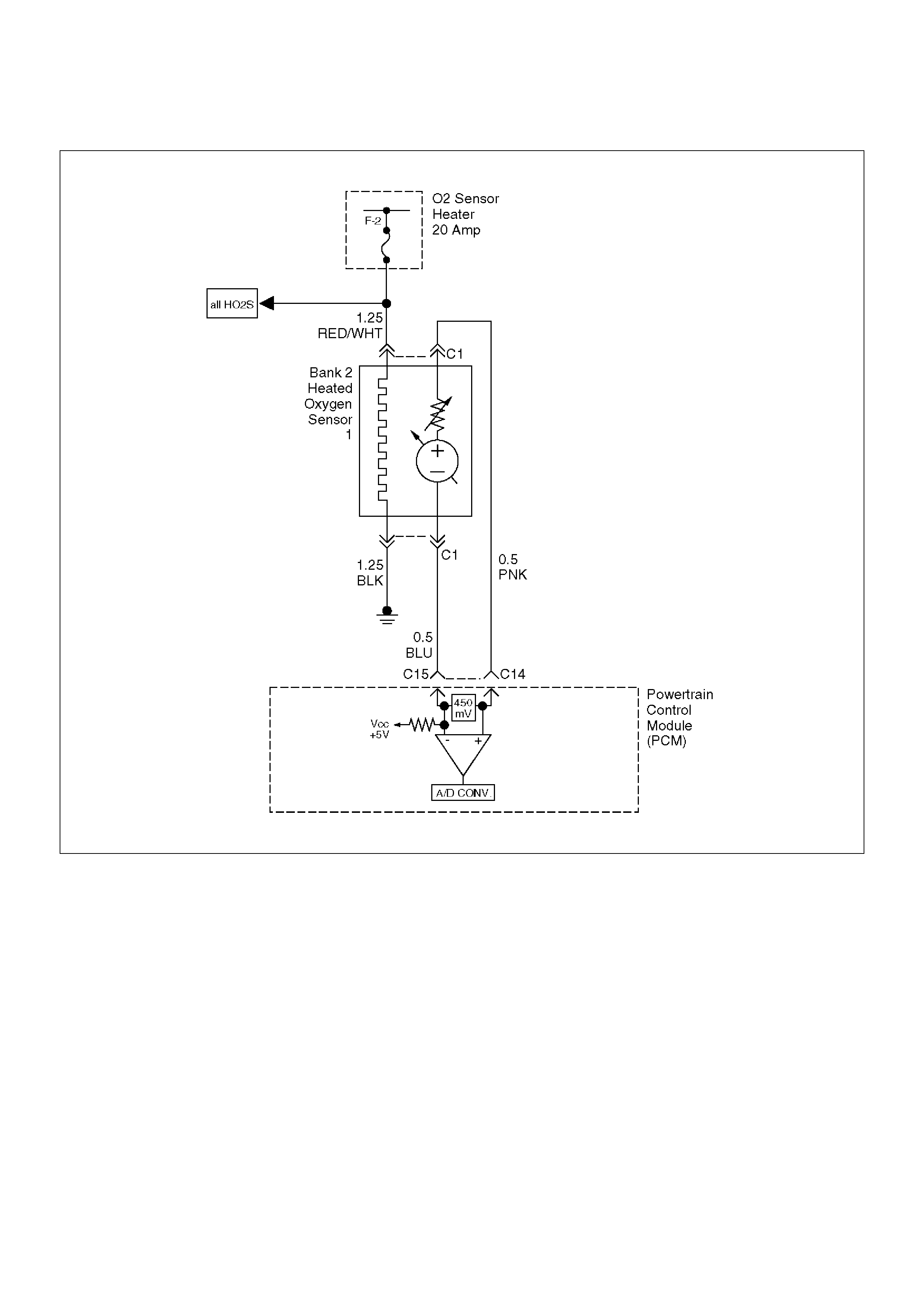
Diagnostic Trouble Code (DTC) P0175 Fuel Trim System Rich Bank 2
D06RW031
Circuit Description
To provide the best possible combination of driveability,
fuel economy, and emission control, a “closed loop” air/
fuel metering system is used. While in “closed loop,”
the powertrain control module (PCM) monitors the Bank
1 HO2S 1 and Bank 2 HO2S 1 signals and adjusts fuel
delivery based upon the HO2S signal voltages. A
change made to fuel delivery will be indicated by the
long and short term fuel trim values which can be
monitored with a Tech 2. Ideal fuel trim values are
around 0%; if the HO2S signals are indicating a lean
condition the PCM will add fuel, resulting in fuel trim
values above 0%. If a rich condition is detected, the fuel
trim values will be below 0%, indicating that the PCM is
reducing the amount of fuel delivered. If an excessively
rich condition is detected on Bank 2, the PCM will set
DTC P0175.
The PCM's maximum authority to control long term fuel
trim allows a range between –15%(automatic
transmission) or –12%(manual transmission) and
+20%. The PCM's maximum authority to control short
term fuel trim allows a range between –11% and +20%.
The PCM monitors fuel trim under various engine
speed/load fuel trim cells before determining the status
of the fuel trim diagnostic.
Conditions for Setting the DTC
• No Tech 2 test is being run.
• None of the following DTCs are set: idle system,
EGR, HO2S, (response, transition, open, low volts,
no activity), MAF, TPS, MAP, IAT, canister purge,
EVAP, injector circuit, or misfire.
• Engine coolant temperature is between 25°C (77°F)
and 100°C (212°F).
• Intake air temperature is between –40°C (–40°F) and
120°C (248°F).

•Manifold absolute pressure is between 24 kPa and
99 kPa.
•Throttle angle is steady below 95%.
•Vehicle speed is below 136 km/h (85 mph).
•Engine speed is between 400 and 6,000 RPM.
•Barometric pressure is greater than 72.5 kPa.
•Mass air flow is between 2 g/second and 200 g/
second.
•Ignition voltage is above 9.5 volts.
•Fuel system is in “closed loop.”
Action Taken When the DTC Sets
•The PCM will illuminate the malfunction indicator
lamp (MIL) after the second consecutive trip in which
the failure is detected.
•The PCM will store conditions which were present
when the DTC was set as Freeze Frame and in the
Failure Records data.
Conditions for Clearing the MIL/DTC
•DTC P0175 can be cleared by using the Tech 2
“Clear Info” function or by disconnecting the PCM
battery feed.
Diagnostic Aids
Check for the following conditions:
•Poor connection at PCM – Inspect harness
connectors for backed -out terminals, improper
mating, broken locks, improperly formed or damaged
terminals, and poor terminal-to-wire connection.
•Damaged harness – Inspect the wiring harness for
damage. If the harness appears to be OK, observe
the Bank 2 HO2S 1 display on the Tech 2 while
moving connectors and wiring harnesses related to
the engine harness. A change in the display will
indicate the location of the fault.
Reviewing the Failure Records Vehicle mileage since
the diagnostic test last failed may help determine how
often the condition that caused the DTC to be set
occurs. This may assist in diagnosing the condition.
Test Description
Number(s) below refer to the step number(s) on the
Diagnostic Chart.
2. DTCs other than P0172 and P0175 may indicate a
condition present which may cause a lean condition.
If this is the case, repairing the condition which
caused the other DTC will most likely correct the
DTC P0172/P0175.
4. If the DTC P0175 test passes while the Failure
Records conditions are being duplicated, the rich
condition is intermittent. Refer to Diagnostic Aids or
Symptoms for additional information on diagnosing
intermittent problems.

DTC P0175 – Fuel Trim System Rich Bank 2
StepActionValue(s)YesNo
1 Was the "On-Board Diagnostic (OBD) System Check"
performed? — Go to Step 2
Go to OBD
System Check
2 Are any DTCs set other than P0172 and P0175?
—
Go to the
applicable DTC
charts and
repair the other
DTCs before
proceeding with
this chart. Go to Step 3
3 1. Start the engine and operate the vehicle in “closed
loop.”
2. Observe the “BANK 2 L.T. FUEL TRIM” display on
the Tech 2.
Is the displayed value more negative than the
specified value?
L.T. Fuel
Trim: –15%
(auto. trans.)
OR –12%
(man. trans.) Go to Step 5 Go to Step 4
4 1. Review and record the Tech 2 Failure Records
data.
2. Clear the DTC P0172/P0175 and operate the
vehicle to duplicate the Failure Records
conditions.
3. Monitor the Tech 2 “DTC” info for DTC P0175
while operating the vehicle to duplicate the Failure
Records conditions.
4. Continue operating the vehicle until the DTC
P0175 test runs.
5. Note the test result.
Does the Tech 2 indicate DTC P0175 failed this
ignition? — Go to Step 5
The rich
condition is not
present. If a
driveability
symptom still
exists, refer to
Symptoms.
5 Was DTC P0172 also set? — Go to Step 6 Go to Step 15
6 Visually and physically inspect the air filter element
and replace it if necessary.
Did the air filter require replacement? — Verify repair Go to Step 7
7 Visually and physically inspect the air intake duct for
collapse or restriction and repair if necessary.
Did your inspection reveal a problem requiring repair? — Verify repair Go to Step 8
8 Inspect the MAF sensor inlet screen for damage or for
the presence of foreign objects which may partially
block air flow through the screen and correct any
problem found.
Did your inspection of the MAF sensor reveal a
condition requiring repair or replacement? — Verify repair Go to Step 9
9 Start the engine and note the idle quality.
Is a low or unsteady idle being experienced? — Go to Step 10 Go to Step 11
10 1. Turn the ignition off and physically inspect the
throttle body bore, throttle plate, and IAC
passages for coking and foreign objects.
2. If a problem was found, repair as necessary.
Did your inspection reveal a condition requiring
repair? — Verify repair Go to Step 11

11 1.Disconnect the vacuum hose from the fuel
pressure regulator and inspect the hose for the
presence of fuel.
2.If fuel is present in the vacuum hose, replace the
fuel pressure regulator (refer to Fuel Metering
System).
Did the fuel pressure regulator require replacement?—Verify repairGo to Step 12
12 1.Ignition “ON,” engine “OFF.”
2.Monitor the TP Angle display on the Tech 2 while
slowly depressing the accelerator pedal.
Does the TP Angle display increase steadily and
evenly from minimum value at closed throttle to
maximum value at wide-open throttle?
Minimum 0%
Maximum
100%Go to Step 13 Go to Step 18
13 1.Disconnect the MAF sensor electrical connector.
2.Operate the vehicle in “closed loop” while
monitoring the “BANK 1 L.T. FUEL TRIM” and
“BANK 1 S.T. FUEL TRIM” display on the Tech 2.
Did both values change to near the specified value?0%Go to Step 19 Go to Step 14
14 1.Perform the “Fuel System Pressure Test.”
2.If Fuel System Pressure Test isolates a problem,
repair as necessary (refer to Engine Fuel or Fuel
Metering System).
Did the Fuel System Pressure Test isolate a condition
requiring repair?—Verify repairGo to Step 16
15 Replace the PCM.
Important: The replacement PCM must be
programmed. Refer to Sections OC1 Service
Programming System and 11A1 6VE1 Immobiliser.
Is the action complete? — Verify repair —
16 1. Perform the “Injector Balance Test.”
2. If the Injector Balance Test isolates a problem,
repair as necessary (refer to Fuel Metering
System).
Did the Injector Balance Test isolate a problem
requiring repair? — Verify repair Go to Step 17
17 1. Remove and visually/physically inspect the Bank
2 HO2S 1 for silicon contamination. This will be
indicated by a powdery white deposit on the
portion of the HO2S that is exposed to the exhaust
stream.
2. If contamination is evident on the Bank 2 HO2S 1,
replace the contaminated sensor.
Did the sensor require replacement? — Verify repair
Refer to
Diagnostic Aids
18 1. Check the TP sensor mounting screws and tighten
or replace them as necessary if they are loose or
missing.
2. If the screws are OK, replace the TP sensor.
Is the action complete? — Verify repair —
19 Replace the MAF sensor.
Is the action complete? — Verify repair —
Step Action Value(s) Yes No
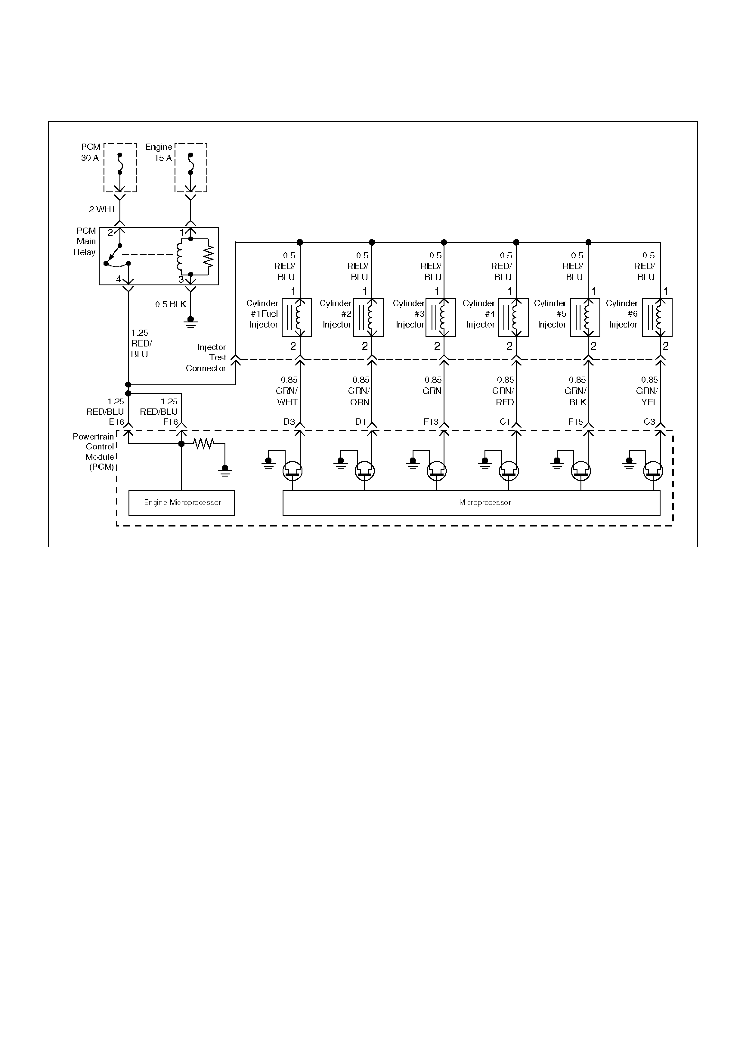
Diagnostic Trouble Code (DTC) P0201 Injector 1 Control Circuit
D06RW034
Circuit Description
The powertrain control module (PCM) has six individual
injector driver circuits. Each controls an injector. When
a driver circuit is grounded by the PCM, the injector is
activated. The PCM monitors the current in each driver
circuit. The voltage on each driver is monitored to
detect a fault. If the voltage is not what the PCM
expects to monitor on the circuit, a DTC is set. This
DTC is also set if an injector driver is shorted to voltage
or if there is an open circuit.
Conditions for Setting the DTC
• The battery voltage is more than 9 volts.
• The engine is turning, determined by 58X crankshaft
position input signal.
• The injector voltage does not equal the ignition
voltage when the injector is commanded “OFF” or the
injector voltage does not equal 0 volts when the
injector is commanded “ON.”
• The above conditions are met for 15 seconds.
Action Taken When the DTC Sets
• The PCM will illuminate the malfunction indicator
lamp (MIL) the first time the fault is detected.
• The PCM will store conditions which were present
when the DTC was set as Freeze Frame and in the
Failure Records data.
Conditions for Clearing the MIL/DTC
• DTC P0201 can be cleared by using the Tech 2
“Clear Info” function or by disconnecting the PCM
battery feed.
Diagnostic Aids
An injector driver circuit that is open or shorted to
voltage will cause a DTC P0201 to set. It will also cause
a misfire due to an inoperative injector. A misfire DTC
will also be set indicating which cylinder is inoperative.
Long term and short term fuel trims that are excessively
high or low are a good indication that an injector is
faulty.
Use Fuel Injector Coil Test Procedure to check for faulty
injectors.
Test Description
The number(s) below refer to the step number(s) on the
Diagnostic Chart.
3. This step determines if DTC P0201 is the result of a
hard failure or an intermittent condition.
5. A special injector test connector is provided so that
the injectors can be electrically tested without
removal of the manifold. On the Trooper, the special
7-way gray connector is located at the front of the
charcoal canister. The test connector can be
identified by the blue connector lock which is
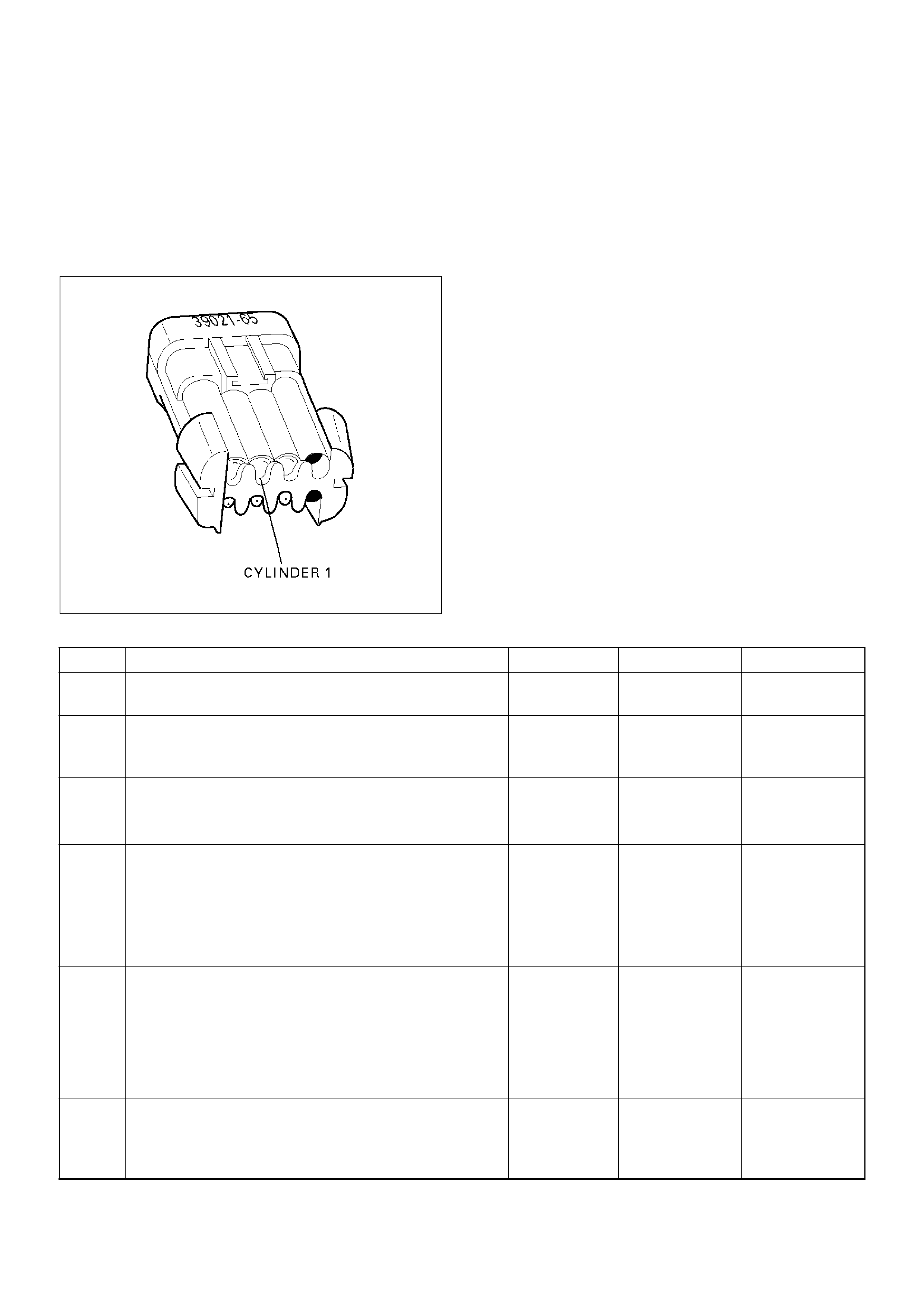
tethered to the wiring harness. If the light for cylinder
1 is “ON” steady before cranking the engine as well
as while cranking the engine, then the injector driver
circuit is shorted to ground.
If the test light blinks while cranking, the PCM and
the wiring to the injectors are OK. The Fuel Injector
Coil Test Procedure will check if the injectors are
faulty.
R321054
7. Because the test light was “ON” steady, voltage to
the injector is OK, but the driver circuit is grounded at
all times. This step determines if the circuit is
shorted to ground or the PCM is faulty.
9. The reading should be about 12-14W.
10. Locating the open in the harness or in the injector
will require removal of the manifold to provide
access.
DTC P0201 – Injector 1 Control Circuit
StepActionValue(s)YesNo
1 Was the “On-Board Diagnostic (OBD) System Check”
performed? — Go to Step 2
Go to OBD
System Check
2 Will the engine start?
—Go to Step 3
Go to Engine
Cranks But Will
Not Run chart
3 1. Install the Tech 2. Clear the DTC.
2. Idle the engine for one minute.
Does DTC P0201 reset? — Go to Step 5 Go to Step 4
4 1. Review the Freeze Frame data with the ignition
“ON” and the engine “OFF” and note the
parameters.
2. Operate the vehicle within the Freeze Frame
conditions as noted.
Does P0201 reset? — Go to Step 5
Go to
Diagnostic Aids
5 1. Engine “OFF.”
2. Disconnect the injector connector.
3. Install an injector test light 5-8840-2636-0 on the
injector test connector.
4. Crank the engine and note the light.
Does the injector test light blink? —
Go to Fuel
Injector Coil
Test Procedure Go to Step 6
6 Note whether the injector test light for cylinder 1 was
“OFF” or “ON” steady in step 5.
Was the test light “ON” steady while cranking the
engine? — Go to Step 7 Go to Step 9

7 1.Disconnect the PCM connector for the affected
injectors.
2.With a test light connected to B+, probe the
affected injector driver circuit.
Does the test light illuminate?—Go to Step 8 Go to Step 15
8 Repair short to ground in the injector driver circuit.
Is the action complete?—
Go to OBD
System Check —
9 1.Disconnect the injector test connector.
2.At the injector side of the harness, connect an
ohmmeter between the positive wire (red with blue
tracer) and the wire for cylinder 1 (green with
white tracer).
Does the ohmmeter indicate continuity?—Go to Step 11 Go to Step 10
10 Repair the open injector harness wire or open injector.
Is the action complete?—Verify repair—
11 At the PCM side of the injector test connector, check
the green/white wire for a short to voltage.
Was there a short to voltage?—Go to Step 12 Go to Step 13
12 Repair the short to voltage.
Is the action complete?—Verify repair—
13 Check for an open circuit between the injector test
connector and the PCM.
Was there an open circuit?—Go to Step 14 Go to Step 15
14 Repair the open circuit.
Is the action complete?—Verify repair—
15 Replace the PCM.
Important: The replacement PCM must be
programmed. Refer to Sections OC1 Service
Programming System and 11A1 6VE1 Immobiliser.
Is the action complete? — Verify repair —
Step Action Value(s) Yes No

Diagnostic Trouble Code (DTC) P0202 Injector 2 Control Circuit
D06RW034
Circuit Description
The powertrain control module (PCM) has six individual
injector driver circuits. Each controls an injector. When
a driver circuit is grounded by the PCM, the injector is
activated. The PCM monitors the current in each driver
circuit. The voltage on each driver is monitored to
detect a fault. If the voltage is not what the PCM
expects to monitor on the circuit, a DTC is set. This
DTC is also set if an injector driver is shorted to voltage
or if there is an open circuit.
Conditions for Setting the DTC
• The battery voltage is more than 9 volts.
• The engine is turning, determined by 58X crankshaft
position input signal.
• The injector voltage does not equal the ignition
voltage when the injector is commanded “OFF” or the
injector voltage does not equal 0 volts when the
injector is commanded “ON.”
• The above conditions are met for 15 seconds.
Action Taken When the DTC Sets
• The PCM will illuminate the malfunction indicator
lamp (MIL) the first time the fault is detected.
• The PCM will store conditions which were present
when the DTC was set as Freeze Frame and in the
Failure Records data.
Conditions for Clearing the MIL/DTC
• DTC P0202 can be cleared by using the Tech 2
“Clear Info” function or by disconnecting the PCM
battery feed.
Diagnostic Aids
An injector driver circuit that is open or shorted to
voltage will cause a DTC P0202 to set. It will also cause
a misfire due to an inoperative injector. A misfire DTC
will also be set indicating which cylinder is inoperative.
Long term and short term fuel trims that are excessively
high or low are a good indication that an injector is
faulty.
Use Fuel Injector Coil Test Procedure to check for faulty
injectors.
Test Description
The number(s) below refer to the step number(s) on the
Diagnostic Chart.
3. This step determines if DTC P0202 is the result of a
hard failure or an intermittent condition.
5. A special injector test connector is provided so that
the injectors can be electrically tested without
removal of the manifold. On the Trooper, the special
7-way gray connector is located at the front of the
charcoal canister. The test connector can be
identified by the blue connector lock which is

tethered to the wiring harness. If the light for cylinder
2 is “ON” steady before cranking the engine as well
as while cranking the engine, then the injector driver
circuit is shorted to ground.
If the test light blinks while cranking, the PCM and
the wiring to the injectors are OK. The Fuel Injector
Coil Test Procedure will check if the injectors are
faulty.
R321055
7. Because the test light was “ON” steady, voltage to
the injector is OK, but the driver circuit is grounded at
all times. This step determines if the circuit is
shorted to ground or the PCM is faulty.
9. The reading should be about 12-14W.
10. Locating the open in the harness or in the injector
will require removal of the manifold to provide
access.
DTC P0202 – Injector 2 Control Circuit
StepActionValue(s)YesNo
1 Was the “On-Board Diagnostic (OBD) System Check”
performed? — Go to Step 2
Go to OBD
System Check
2 Will the engine start?
—Go to Step 3
Go to Engine
Cranks But Will
Not Run chart
3 1. Install the Tech 2. Clear the DTC.
2. Idle the engine for one minute.
Does DTC P0202 reset? — Go to Step 5 Go to Step 4
4 1. Review the Freeze Frame data with the ignition
“ON” and the engine “OFF” and note the
parameters.
2. Operate the vehicle within the Freeze Frame
conditions as noted.
Does P0202 reset? — Go to Step 5
Go to
Diagnostic Aids
5 1. Engine “OFF.”
2. Disconnect the injector test connector.
3. Install an injector test light 5-8840-2636-0 on
injector connector.
4. Crank the engine and note the light.
Does the cylinder 2 test light blink? —
Go to Fuel
Injector Coil
Test Procedure Go to Step 6
6 Note whether the injector test light for cylinder 2 was
“OFF” or “ON” steady in step 5.
Was the test light “ON” steady while cranking the
engine? — Go to Step 7 Go to Step 9

7 1.Disconnect the PCM connector for the affected
injectors.
2.With a test light connected to B+, probe the
affected injector driver circuit.
Does the test light illuminate?—Go to Step 8 Go to Step 15
8 Repair short to ground in the injector driver circuit.
Is the action complete?—
Go to OBD
System Check —
9 1.Disconnect the injector test connector.
2.At the injector side of the harness, connect an
ohmmeter between the positive wire (red with blue
tracer) and the wire for cylinder 2 (green with
orange tracer).
Does the ohmmeter indicate continuity?—Go to Step 11 Go to Step 10
10 Repair the open injector harness wire or open injector.
Is the action complete?—Verify repair—
11 At the PCM side of the injector test connector, check
the green/orange wire for a short to voltage.
Was there a short to voltage?—Go to Step 12 Go to Step 13
12 Repair the short to voltage.
Is the action complete?—Verify repair—
13 Check for an open circuit between the injector test
connector and the PCM.
Was there an open circuit?—Go to Step 14 Go to Step 15
14 Repair the open circuit.
Is the action complete?—Verify repair—
15 Replace the PCM.
Important: The replacement PCM must be
programmed. Refer to Sections OC1 Service
Programming System and 11A1 6VE1 Immobiliser.
Is the action complete? — Verify repair —
Step Action Value(s) Yes No

Diagnostic Trouble Code (DTC) P0203 Injector 3 Control Circuit
D06RW034
Circuit Description
The powertrain control module (PCM) has six individual
injector driver circuits. Each controls an injector. When
the driver circuit is grounded by the PCM, the injector is
activated. The PCM monitors the current in each driver
circuit. The voltage on each driver is monitored to
detect a fault. If the voltage is not what the PCM
expects to monitor on the circuit, a DTC is set. This
DTC is also set if an injector driver is shorted to voltage
or if there is an open circuit.
Conditions for Setting the DTC
• The battery voltage is more than 9 volts.
• The engine is turning, determined by the 58X
crankshaft position input signal.
• The injector voltage does not equal the ignition
voltage when the injector is commanded “OFF” or the
injector voltage does not equal 0 volts when the
injector is commanded “ON.”
• The above conditions are met for 15 seconds.
Action Taken When the DTC Sets
• The PCM will illuminate the malfunction indicator
lamp (MIL) the first time the fault is detected.
• The PCM will store conditions which were present
when the DTC was set as Freeze Frame and in the
Failure Records data.
Conditions for Clearing the MIL/DTC
• DTC P0203 can be cleared by using the Tech 2
“Clear Info” function or by disconnecting the PCM
battery feed.
Diagnostic Aids
An injector driver circuit that is open or shorted to
voltage will cause a DTC P0203 to set. It will also cause
a misfire due to an inoperative injector. A misfire DTC
will also be set indicating which cylinder is inoperative.
Long term and short term fuel trims that are excessively
high or low are a good indication that an injector is
faulty.
Use Fuel Injector Coil Test Procedure to check for faulty
injectors.
Test Description
The number(s) below refer to the step number(s) on the
Diagnostic Chart.
3. This step determines if DTC P0203 is the result of a
hard failure or an intermittent condition.
5. A special injector test connector is provided so that
the injectors can be electrically tested without
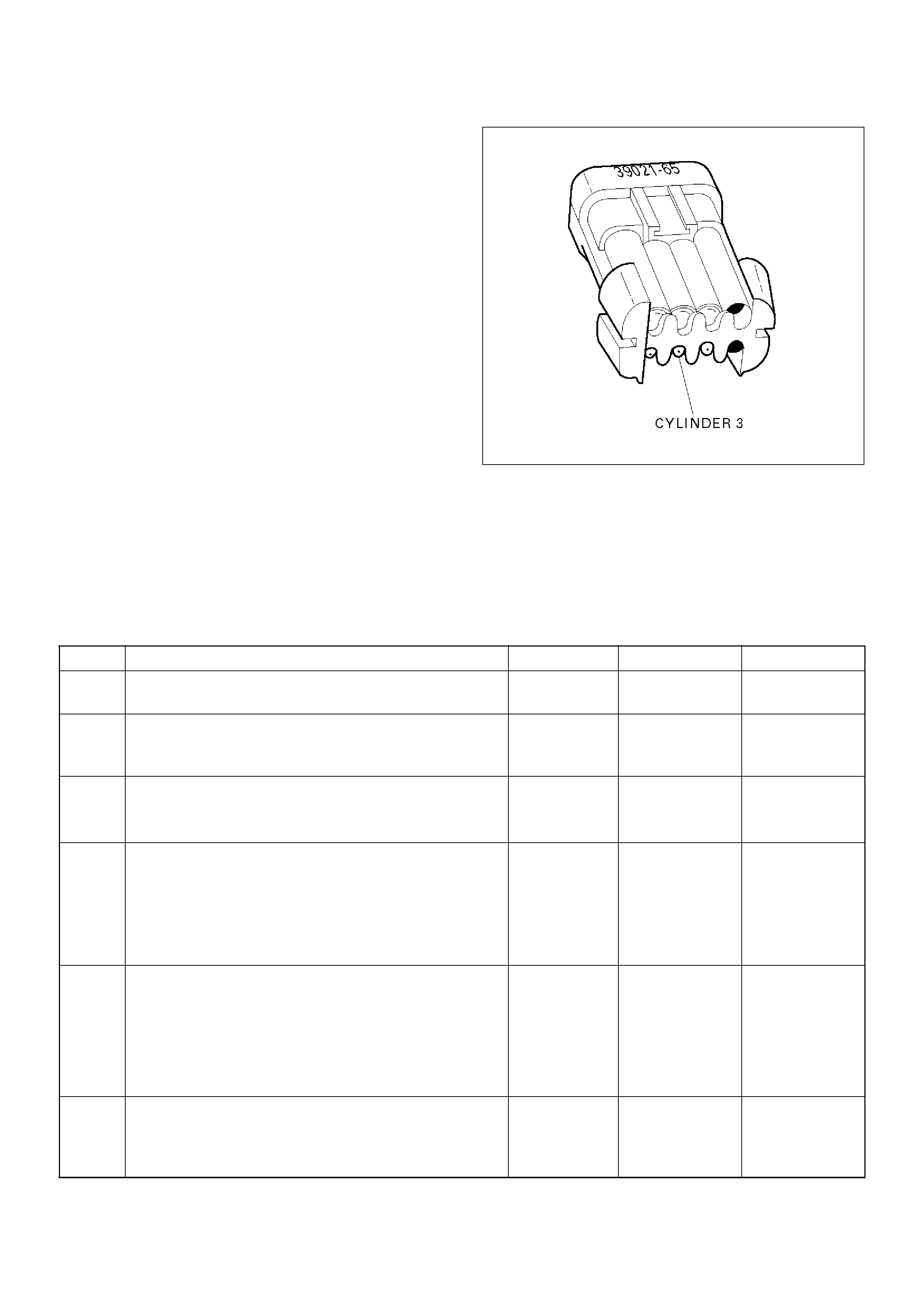
removal of the manifold. On the Trooper, the special
7-way gray connector is located at the front of the
charcoal canister. The test connector can be
identified by the blue connector lock which is
tethered to the wiring harness. If the light for cylinder
3 is “ON” steady before cranking the engine as well
as while cranking the engine, then the injector driver
circuit is shorted to ground.
If the test light blinks while cranking, the PCM and
the wiring to the injectors are OK. The Fuel Injector
Coil Test Procedure will check if the injectors are
faulty.
R321056
7. Because the test light was “ON” steady, voltage to
the injector is OK, but the driver circuit is grounded at
all times. This step determines if the circuit is
shorted to ground or the PCM is faulty.
9. The reading should be about 12-14W.
10. Locating the open in the harness or in the injector
will require removal of the manifold to provide
access.
DTC P0203 – Injector 3 Control Circuit
StepActionValue(s)YesNo
1 Was the “On-Board Diagnostic (OBD) System Check”
performed? — Go to Step 2
Go to OBD
System Check
2 Will the engine start?
—Go to Step 3
Go to Engine
Cranks But Will
Not Run chart
3 1. Install the Tech 2. Clear the DTC.
2. Idle the engine for one minute.
Does DTC P0203 reset? — Go to Step 5 Go to Step 4
4 1. Review the Freeze Frame data with the ignition
“ON” and the engine “OFF” and note the
parameters.
2. Operate the vehicle within the Freeze Frame
conditions as noted.
Does P0203 reset? — Go to Step 5
Go to
Diagnostic Aids
5 1. Engine “OFF.”
2. Disconnect the injector test connector .
3. Install an injector test light 5-8840-2636-0 on
injector connector.
4. Crank the engine and note the light.
Does the cylinder 3 test light blink? —
Go to Fuel
Injector Coil
Test Procedure Go to Step 6
6 Note whether the injector test light for cylinder 3 was
“OFF” or “ON” steady in step 5.
Was the test light “ON” steady while cranking the
engine? — Go to Step 7 Go to Step 9

7 1.Disconnect the PCM connector for the affected
injectors.
2.With a test light connected to B+, probe the
affected injector driver circuit.
Does the test light illuminate?—Go to Step 8 Go to Step 15
8 Repair short to ground in the injector driver circuit.
Is the action complete?—
Go to OBD
System Check —
9 1.Disconnect the injector test connector.
2.At the injector side of the harness, connect an
ohmmeter between the positive wire (red with blue
tracer) and the wire for cylinder 3 (green).
Does the ohmmeter indicate continuity?—Go to Step 11 Go to Step 10
10 Repair the open injector harness wire or open injector.
Is the action complete?—Verify repair—
11 At the PCM side of the injector test connector, check
the green wire for a short to voltage.
Was there a short to voltage?—Go to Step 12 Go to Step 13
12 Repair the short to voltage.
Is the action complete?—Verify repair—
13 Check for an open circuit between the injector test
connector and the PCM.
Was there an open circuit?—Go to Step 14 Go to Step 15
14 Repair the open circuit.
Is the action complete?—Verify repair—
15 Replace the PCM.
Important: The replacement PCM must be
programmed. Refer to Sections OC1 Service
Programming System and 11A1 6VE1 Immobiliser.
Is the action complete? — Verify repair —
Step Action Value(s) Yes No

Diagnostic Trouble Code (DTC) P0204 Injector 4 Control Circuit
D06RW034
Circuit Description
The powertrain control module (PCM) has six individual
injector driver circuits. Each controls an injector. When
the driver circuit is grounded by the PCM, the injector is
activated. The PCM monitors the current in each driver
circuit. The voltage on each driver is monitored to
detect a fault. If the voltage is not what the PCM
expects to monitor on the circuit, a DTC is set. This
DTC is also set if an injector driver is shorted to voltage
or if there is an open circuit.
Conditions for Setting the DTC
• The battery voltage is more than 9 volts.
• The engine is turning, determined by the 58X
crankshaft position input signal.
• The injector voltage does not equal the ignition
voltage when the injector is commanded “OFF” or the
injector voltage does not equal 0 volts when the
injector is commanded “ON.”
• The above conditions are met for 15 seconds.
Action Taken When the DTC Sets
• The PCM will illuminate the malfunction indicator
lamp (MIL) the first time the fault is detected.
• The PCM will store conditions which were present
when the DTC was set as Freeze Frame and in the
Failure Records data.
Conditions for Clearing the MIL/DTC
• DTC P0204 can be cleared by using the Tech 2
“Clear Info” function or by disconnecting the PCM
battery feed.
Diagnostic Aids
An injector driver circuit that is open or shorted to
voltage will cause a DTC P0204 to set. It will also cause
a misfire due to an inoperative injector. A misfire DTC
will also be set indicating which cylinder is inoperative.
Long term and short term fuel trims that are excessively
high or low are a good indication that an injector is
faulty.
Use Fuel Injector Coil Test Procedure to check for faulty
injectors.
Test Description
The number(s) below refer to the step number(s) on the
Diagnostic Chart.
3. This step determines if DTC P0204 is the result of a
hard failure or an intermittent condition.
5. A special injector test connector is provided so that
the injectors can be electrically tested without
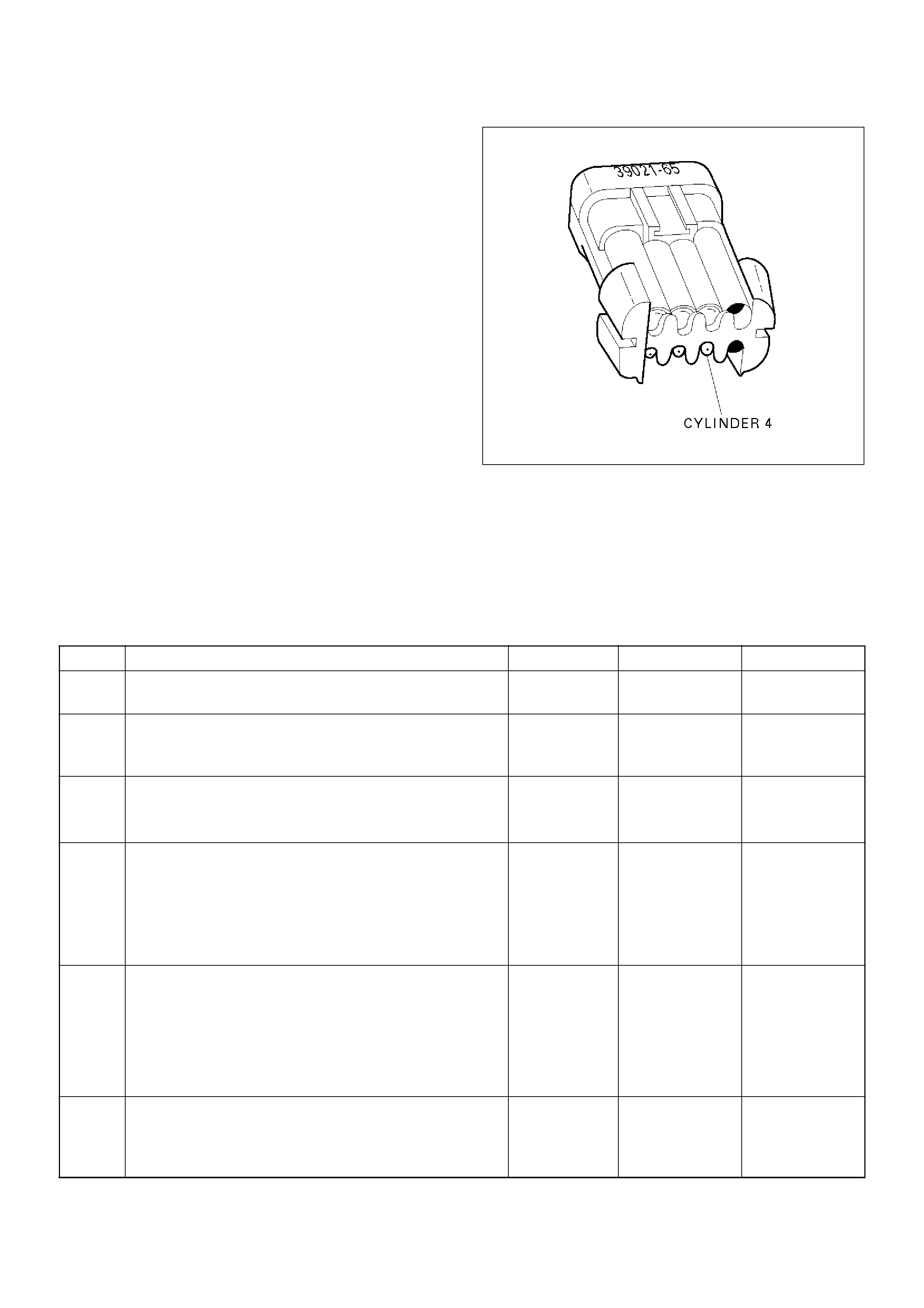
removal of the manifold. On the Trooper, the special
7-way gray connector is located at the front of the
charcoal canister. The test connector can be
identified by the blue connector lock which is
tethered to the wiring harness. If the light for
cylinder 4 is “ON” steady before cranking the engine
as well as while cranking the engine, then the
injector driver circuit is shorted to ground.
If the test light blinks while cranking, the PCM and
the wiring to the injectors are OK. The Fuel Injector
Coil Test Procedure will check if the injectors are
faulty.
R321057
7. Because the test light was “ON” steady, voltage to
the injector is OK, but the driver circuit is grounded at
all times. This step determines if the circuit is
shorted to ground or the PCM is faulty.
9. The reading should be about 12-14W.
10. Locating the open in the harness or in the injector
will require removal of the manifold to provide
access.
DTC P0204 – Injector 4 Control Circuit
StepActionValue(s)YesNo
1 Was the “On-Board Diagnostic (OBD) System Check”
performed? — Go to Step 2
Go to OBD
System Check
2 Will the engine start?
—Go to Step 3
Go to Engine
Cranks But Will
Not Run chart
3 1. Install the Tech 2. Clear the DTC.
2. Idle the engine for one minute.
Does DTC P0204 reset? — Go to Step 5 Go to Step 4
4 1. Review the Freeze Frame data with the ignition
“ON” and the engine “OFF” and note the
parameters.
2. Operate the vehicle within the Freeze Frame
conditions as noted.
Does P0204 reset? — Go to Step 5
Go to
Diagnostic Aids
5 1. Engine “OFF.”
2. Disconnect the injector test connector.
3. Install an injector test light 5-8840-2636-0 on
injector connector.
4. Crank the engine and note the light.
Does the cylinder 4 test light blink? —
Go to Fuel
Injector Coil
Test Procedure Go to Step 6
6 Note whether the injector test light for cylinder 4 was
“OFF” or “ON” steady in step 5.
Was the test light “ON” steady while cranking the
engine? — Go to Step 7 Go to Step 9

7 1.Disconnect the PCM connector for the affected
injectors.
2.With a test light connected to B+, probe the
affected injector driver circuit.
Does the test light illuminate?—Go to Step 8 Go to Step 15
8 Repair short to ground in the injector driver circuit.
Is the action complete?—
Go to OBD
System Check —
9 1.Disconnect the injector test connector.
2.At the injector side of the harness, connect an
ohmmeter between the positive wire (red with blue
tracer) and the wire for cylinder 4 (green/red).
Does the ohmmeter indicate continuity?—Go to Step 11 Go to Step 10
10 Repair the open injector harness wire or open injector.
Is the action complete?—Verify repair—
11 At the PCM side of the injector test connector, check
the green/red wire for a short to voltage.
Was there a short to voltage?—Go to Step 12 Go to Step 13
12 Repair the short to voltage.
Is the action complete?—Verify repair—
13 Check for an open circuit between the injector test
connector and the PCM.
Was there an open circuit?—Go to Step 14 Go to Step 15
14 Repair the open circuit.
Is the action complete?—Verify repair—
15 Replace the PCM.
Important: The replacement PCM must be
programmed. Refer to Sections OC1 Service
Programming System and 11A1 6VE1 Immobiliser.
Is the action complete? — Verify repair —
Step Action Value(s) Yes No

Diagnostic Trouble Code (DTC) P0205 Injector 5 Control Circuit
D06RW034
Circuit Description
The powertrain control module (PCM) has six individual
injector driver circuits. Each controls an injector. When
the driver circuit is grounded by the PCM, the injector is
activated. The PCM monitors the current in each driver
circuit. If the voltage is not what the PCM expects to
monitor on the circuit, a DTC is set. This DTC is also
set if an injector driver is shorted to voltage or if there is
an open circuit.
Conditions for Setting the DTC
• The battery voltage is more than 9 volts.
• The engine is turning, determined by the 58X
crankshaft position input signal.
• The injector voltage does not equal the ignition
voltage when the injector is commanded “OFF” or the
injector voltage does not equal 0 volts when the
injector is commanded “ON.”
• The above conditions are met for 15 seconds.
Action Taken When the DTC Sets
• The PCM will illuminate the malfunction indicator
lamp (MIL) the first time the fault is detected.
• The PCM will store conditions which were present
when the DTC was set as Freeze Frame and in the
Failure Records data.
Conditions for Clearing the MIL/DTC
• DTC P0205 can be cleared by using the Tech 2
“Clear Info” function or by disconnecting the PCM
battery feed.
Diagnostic Aids
An injector driver circuit that is open or shorted to
voltage will cause a DTC P0205 to set. It will also cause
a misfire due to an inoperative injector. A misfire DTC
will also be set indicating which cylinder is inoperative.
Long term and short term fuel trims that are excessively
high or low are a good indication that an injector is
faulty.
Use Fuel Injector Coil Test Procedure to check for faulty
injectors.
Test Description
The number(s) below refer to the step number(s) on the
Diagnostic Chart.
3. This step determines if DTC P0205 is the result of a
hard failure or an intermittent condition.
5. A special injector test connector is provided so that
the injectors can be electrically tested without
removal of the manifold. On the Trooper, the special
7-way gray connector is located at the front of the
charcoal canister. The test connector can be
identified by the blue connector lock which is
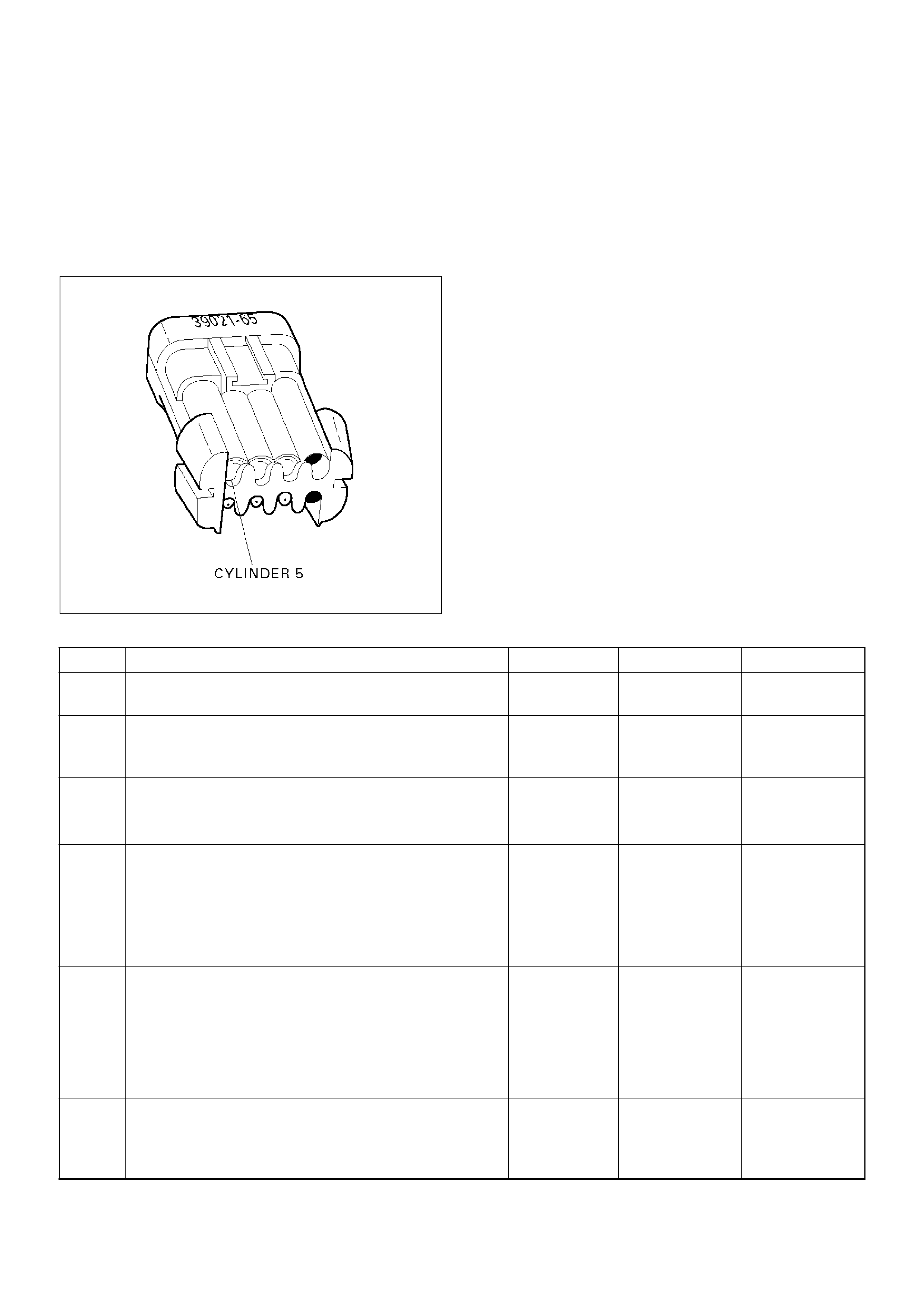
tethered to the wiring harness. If the light for
cylinder 5 is “ON” steady before cranking the engine
as well as while cranking the engine, then the
injector driver circuit is shorted to ground.
If the test light blinks while cranking, the PCM and
the wiring to the injectors are OK. The Fuel Injector
Coil Test Procedure will check if the injectors are
faulty.
R321058
7. Because the test light was “ON” steady, voltage to
the injector is OK, but the driver circuit is grounded at
all times. This step determines if the circuit is
shorted to ground or the PCM is faulty.
9. The reading should be about 12-14W.
10. Locating the open in the harness or in the injector
will require removal of the manifold to provide
access.
DTC P0205 – Injector 5 Control Circuit
StepActionValue(s)YesNo
1 Was the “On-Board Diagnostic (OBD) System Check”
performed? — Go to Step 2
Go to OBD
System Check
2 Will the engine start?
—Go to Step 3
Go to Engine
Cranks But Will
Not Run chart
3 1. Install the Tech 2. Clear the DTC.
2. Idle the engine for one minute.
Does DTC P0205 reset? — Go to Step 5 Go to Step 4
4 1. Review the Freeze Frame data with the ignition
“ON” and the engine “OFF” and note the
parameters.
2. Operate the vehicle within the Freeze Frame
conditions as noted.
Does P0205 reset? — Go to Step 5
Go to
Diagnostic Aids
5 1. Engine “OFF.”
2. Disconnect the injector test connector.
3. Install an injector test light 5-8840-2636-0 on
injector connector.
4. Crank the engine and note the light.
Does the cylinder 5 test light blink? —
Go to Fuel
Injector Coil
Test Procedure Go to Step 6
6 Note whether the injector test light for cylinder 5 was
“OFF” or “ON” steady in step 5.
Was the test light “ON” steady while cranking the
engine? — Go to Step 7 Go to Step 9

7 1.Disconnect the PCM connector for the affected
injectors.
2.With a test light connected to B+, probe the
affected injector driver circuit.
Does the test light illuminate?—Go to Step 8 Go to Step 15
8 Repair short to ground in the injector driver circuit.
Is the action complete?—
Go to OBD
System Check —
9 1.Disconnect the injector test connector.
2.At the injector side of the harness, connect an
ohmmeter between the positive wire (red with blue
tracer) and the wire for cylinder 5 (green with
black tracer).
Does the ohmmeter indicate continuity?—Go to Step 11 Go to Step 10
10 Repair the open injector harness wire or open injector.
Is the action complete?—Verify repair—
11 At the PCM side of the injector test connector, check
the green/black wire for a short to voltage.
Was there a short to voltage?—Go to Step 12 Go to Step 13
12 Repair the short to voltage.
Is the action complete?—Verify repair—
13 Check for an open circuit between the injector test
connector and the PCM.
Was there an open circuit?—Go to Step 14 Go to Step 15
14 Repair the open circuit.
Is the action complete?—Verify repair—
15 Replace the PCM.
Important: The replacement PCM must be
programmed. Refer to Sections OC1 Service
Programming System and 11A1 6VE1 Immobiliser.
Is the action complete? — Verify repair —
Step Action Value(s) Yes No

Diagnostic Trouble Code (DTC) P0206 Injector 6 Control Circuit
D06RW034
Circuit Description
The powertrain control module (PCM) has six individual
injector driver circuits. Each controls an injector. When
the driver circuit is grounded by the PCM, the injector is
activated. The PCM monitors the current in each driver
circuit. The voltage on each driver is monitored to
detect a fault. If the voltage is not what the PCM
expects to monitor on the circuit, a DTC is set. This
DTC is also set if an injector driver is shorted to voltage
or if there is an open circuit.
Conditions for Setting the DTC
• The battery voltage is more than 9 volts.
• The engine is turning, determined by 58X crankshaft
position input signal.
• The injector voltage does not equal the ignition
voltage when the injector is commanded “OFF” or the
injector voltage does not equal 0 volts when the
injector is commanded “ON.”
• The above conditions are met for 15 seconds.
Action Taken When the DTC Sets
• The PCM will illuminate the malfunction indicator
lamp (MIL) the first time the fault is detected.
• The PCM will store conditions which were present
when the DTC was set as Freeze Frame and in the
Failure Records data.
Conditions for Clearing the MIL/DTC
• DTC P0206 can be cleared by using the Tech 2
“Clear Info” function or by disconnecting the PCM
battery feed.
Diagnostic Aids
An injector driver circuit that is open or shorted to
voltage will cause a DTC P0206 to set. It will also cause
a misfire due to an inoperative injector. A misfire DTC
will also be set indicating which cylinder is inoperative.
Long term and short term fuel trims that are excessively
high or low are a good indication that an injector is
faulty.
Use Fuel Injector Coil Test Procedure to check for faulty
injectors.
Test Description
The number(s) below refer to the step number(s) on the
Diagnostic Chart.
3. This step determines if DTC P0206 is the result of a
hard failure or an intermittent condition.
5. A special injector test connector is provided so that
the injectors can be electrically tested without

removal of the manifold. On the Trooper, the special
7-way gray connector is located at the front of the
charcoal canister. The test connector can be
identified by the blue connector lock which is
tethered to the wiring harness. If the light for
cylinder 6 is “ON” steady before cranking the engine
as well as while cranking the engine, then the
injector driver circuit is shorted to ground.
If the test light blinks while cranking, the PCM and
the wiring to the injectors are OK. The Fuel Injector
Coil Test Procedure will check if the injectors are
faulty.
R321059
7. Because the test light was “ON” steady, voltage to
the injector is OK, but the driver circuit is grounded at
all times. This step determines if the circuit is
shorted to ground or the PCM is faulty.
9. The reading should be about 12-14W.
10. Locating the open in the harness or in the injector
will require removal of the manifold to provide
access.
DTC P0206 – Injector 6 Control Circuit
StepActionValue(s)YesNo
1 Was the “On-Board Diagnostic (OBD) System Check”
performed? — Go to Step 2
Go to OBD
System Check
2 Will the engine start?
—Go to Step 3
Go to Engine
Cranks But Will
Not Run chart
3 1. Install the Tech 2. Clear the DTC.
2. Idle the engine for one minute.
Does DTC P0206 reset? — Go to Step 5 Go to Step 4
4 1. Review the Freeze Frame data with the ignition
“ON” and the engine “OFF” and note the
parameters.
2. Operate the vehicle within the Freeze Frame
conditions as noted.
Does P0206 reset? — Go to Step 5
Go to
Diagnostic Aids
5 1. Engine “OFF.”
2. Disconnect the injector test connector.
3. Install an injector test light 5-8840-2636-0 on
injector connector.
4. Crank the engine and note the light.
Does the cylinder 6 test light blink? —
Go to Fuel
Injector Coil
Test Procedure Go to Step 6
6 Note whether the injector test light for cylinder 6 was
“OFF” or “ON” steady in step 5.
Was the test light “ON” steady while cranking the
engine? — Go to Step 7 Go to Step 9

7 1.Disconnect the PCM connector for the affected
injectors.
2.With a test light connected to B+, probe the
affected injector driver circuit.
Does the test light illuminate?—Go to Step 8 Go to Step 15
8 Repair short to ground in the injector driver circuit.
Is the action complete?—
Go to OBD
System Check —
9 1.Disconnect the injector test connector.
2.At the injector side of the harness, connect an
ohmmeter between the positive wire (red with blue
tracer) and the wire for cylinder 6 (green with
yellow tracer).
Does the ohmmeter indicate continuity?—Go to Step 11 Go to Step 10
10 Repair the open injector harness wire or open injector
Is the action complete?—Verify repair—
11 At the PCM side of the injector test connector, check
the green/yellow wire for a short to voltage.
Was there a short to voltage?—Go to Step 12 Go to Step 13
12 Repair the short to voltage.
Is the action complete?—Verify repair—
13 Check for an open circuit between the injector test
connector and the PCM.
Was there an open circuit?—Go to Step 14 Go to Step 15
14 Repair the open circuit.
Is the action complete?—Verify repair—
15 Replace the PCM.
Important: The replacement PCM must be
programmed. Refer to Sections OC1 Service
Programming System and 11A1 6VE1 Immobiliser.
Is the action complete? — Verify repair —
Step Action Value(s) Yes No
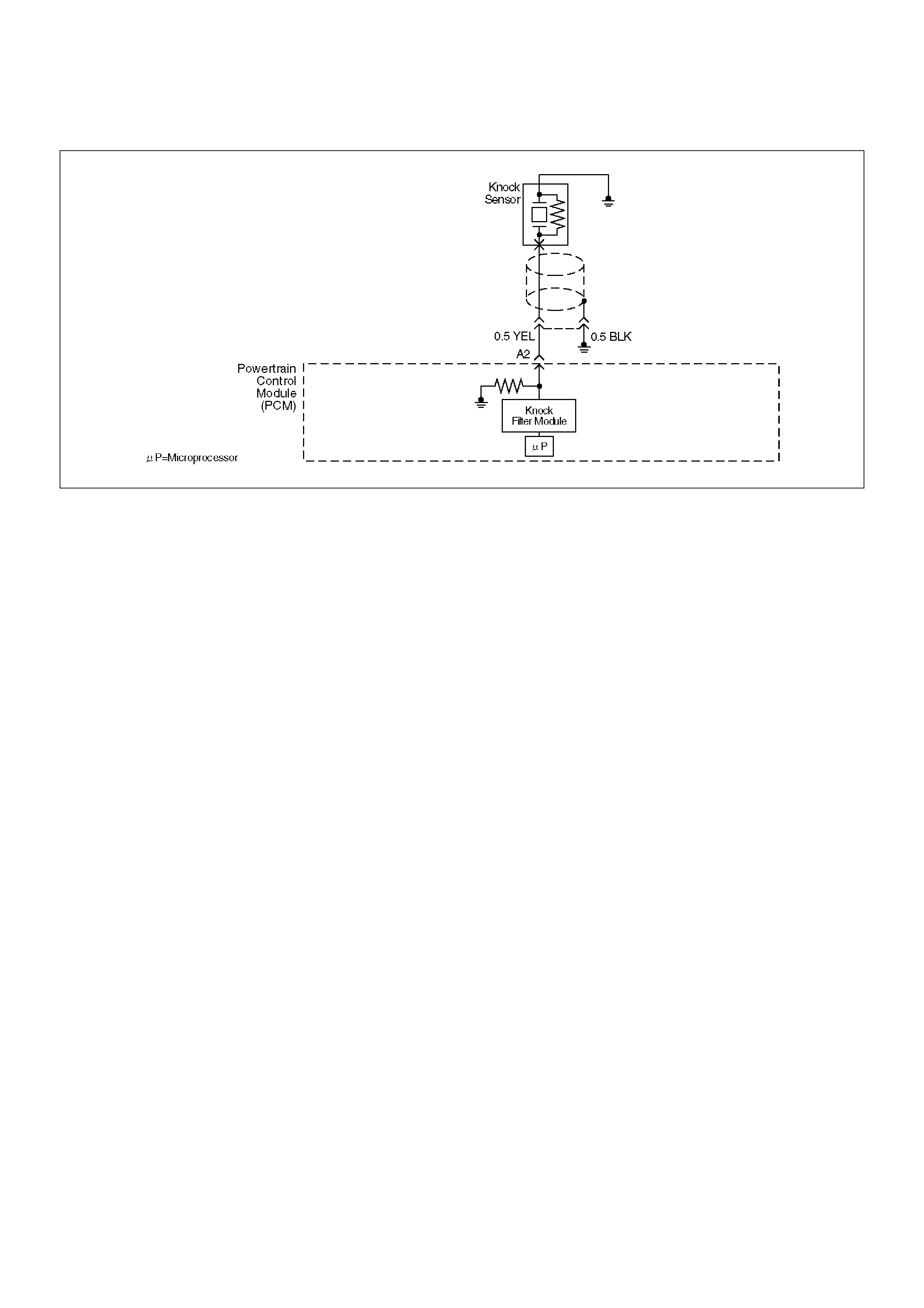
Diagnostic Trouble Code (DTC) P0325 KS Module Circuit
D06RW035
Circuit Description
The knock sensor is used to detect engine detonation,
allowing the powertrain control module (PCM) to retard
ignition control (IC) spark timing based on the knock
sensor (KS) signal being received. The knock sensor
produces an AC signal so that under a no knock
condition the signal on the KS circuit measures about
0.007 V AC. The KS signal's amplitude and frequency
depend upon the amount of knock being experienced.
The PCM contains a non-replaceable knock filter
module called a signal-to-noise enhancement filter
(SNEF) module. This filter module in the PCM
determines whether knock is occurring by comparing
the signal level on the KS circuit with the voltage level
on the noise channel. The noise channel allows the
PCM to reject any false knock signal by knowing the
amount of normal engine mechanical noise present.
Normal engine noise varies depending on engine speed
and load. When the PCM determines that an
abnormally low noise channel voltage level is being
experienced, a DTC P0325 will set.
Conditions for Setting the DTC
• Engine has been running for at least 30 seconds.
• The PCM determines that its internal signal from its
knock filter module indicates a continuous knocking
condition for more than 10 seconds.
Action Taken When the DTC Sets
• The PCM will store conditions which were present
when the DTC was set as Freeze Frame and in the
Failure Records data.
• The PCM will use a “substitute” default spark retard
value of 6 degrees to minimize knock during
conditions when knock is likely to occur.
Conditions for Clearing the MIL/DTC
• DTC P0325 can be cleared by using Tech 2 “Clear
Info” function or by disconnecting the PCM battery
feed.
Diagnostic Aids
Check for the following conditions:
• Poor connection at PCM – Inspect the knock sensor
and PCM connectors for backed-out terminals,
broken locks, and improperly formed or damaged
terminals.
• Misrouted harness – Inspect the knock sensor
harness to ensure that it is not routed too close to
high voltage wires such as spark plug leads.
Reviewing the Failure Records vehicle mileage since
the diagnostic test last failed may help determine how
often the condition that caused the DTC to be set
occurs. This may assist in diagnosing the condition.
Test Description
Number(s) below refer to the step number(s) on the
Diagnostic Chart.
2. Ensures that the fault is present.

DTC P0325 – KS Module Circuit
StepActionValue(s)YesNo
1 Was the “On-Board Diagnostic (OBD) System Check”
performed?—Go to Step 2
Go to OBD
System Check
2 Important: If an engine knock can be heard, repair
the engine mechanical problem before proceeding
with this diagnostic.
1.Operate the vehicle within parameters specified
under criteria included in “Conditions for Setting
the DTC.”
2.Using Tech 2, monitor “Specific DTC” info for DTC
P0325 until the DTC P0325 test runs.
3.Note the test result.
Does Tech 2 indicate DTC P0325 failed this ignition?—Go to Step 4 Go to Step 3
3 1.Ignition “ON,” engine “OFF.”
2.Review and record Tech 2 Failure Records data
for DTC P0325.
3.Operate the vehicle within Failure Records
conditions.
4.Using Tech 2, monitor “Specific DTC” info for DTC
P0325 until the DTC P0325 test runs.
Does Tech 2 indicate DTC P0325 test failed this
ignition?—Go to Step 4
Refer to
Diagnostic Aids
4 Replace the PCM.
Important: The replacement PCM must be
programmed. Refer to Sections OC1 Service
Programming System and 11A1 6VE1 Immobiliser.
Is the action complete? — Verify repair —

Diagnostic Trouble Code (DTC) P0327 KS Sensor Circuit
D06RW035
Circuit Description
The powertrain control module (PCM) uses the knock
sensor to detect engine detonation, allowing the PCM to
retard ignition control (IC) spark timing based on the
knock sensor (KS) signal being received. The knock
sensor produces an AC signal so that under a no knock
condition the signal on the KS circuit measures about
0.007 V AC. The signal amplitude and frequency are
dependent upon the amount of knock being
experienced.
The PCM monitors the KS signal and can diagnose the
KS sensor and circuitry.
Conditions for Setting the DTC
• Engine running for at least 10 seconds.
• The TP sensor is greater than 5%.
• The ECT sensor is greater than 60°C (140°F).
• Engine speed is between 2000 and 4000 RPM.
• The knock sensor signal voltage is less than 0.20
volts, or greater than 4.8 volts.
• All conditions are present for more than 15 seconds.
Action Taken When the DTC Sets
• The PCM will illuminate the malfunction indicator
lamp (MIL) after the second consecutive trip in which
the fault is detected.
• The PCM will store conditions which were present
when the DTC was set as Freeze Frame and in the
Failure Records data.
• The PCM will use a calculated spark retard value to
minimize knock during conditions when knock is likely
to occur. The calculated value will vary based on
engine speed and load.
Conditions for Clearing the MIL/DTC
• DTC P0327 can be cleared by using Tech 2 “Clear
Info” function or by disconnecting the PCM battery
feed.
Diagnostic Aids
Reviewing the Failure Records vehicle mileage since
the diagnostic test last failed may help determine how
often the condition that caused the DTC to be set
occurs. This may assist in diagnosing the condition.
Test Description
Number(s) below refer to the step number(s) on the
Diagnostic Chart.
2. Ensures that the fault is present.
4. The knock sensor is attached to a short jumper
harness, so it can be tested without removing the
intake manifold. A 2-wire connector for the knock
sensor is accessible behind the left rear fuel injector.

DTC P0327 – KS Sensor Circuit
StepActionValue(s)YesNo
1 Was the “On-Board Diagnostic (OBD) System Check”
performed?—Go to Step 2
Go to OBD
System Check
2 Important: If an engine knock can be heard, repair
the engine mechanical problem before proceeding
with this diagnostic.
1. Operate the engine within the conditions specified
in diagnostic support “Conditions for Setting the
DTC.”
2. Using Tech 2, monitor “Specific DTC” info for DTC
P0327 until the DTC P0327 test runs.
3. Note the test result.
Does Tech 2 indicate DTC P0327 failed this ignition? — Go to Step 4 Go to Step 3
3 1. Ignition “ON,” engine “OFF.”
2. Review and record Tech 2 Failure Records data.
3. Operate the vehicle within Failure Records
conditions.
4. Using Tech 2, monitor “Specific DTC” info for DTC
P0327 until the DTC P0327 test runs.
5. Note the test result.
Does Tech 2 indicate DTC P0327 failed this ignition? — Go to Step 4
Refer to
Diagnostic Aids
4 1. Check for a damaged terminal at the knock sensor
connector.
2. If a problem is found, repair as necessary.
Was a problem found? — Verify repair Go to Step 5
5 Using a test light to battery +, check the black/blue
wire (PCM side) to verify that the shield connection is
good.
Did the test light illuminate? — Go to Step 7 Go to Step 6
6 Repair the open shield ground.
Is the action complete? — Verify repair —
7 1. Ignition “OFF,” disconnect the PCM.
2. Check the KS signal circuit for a poor terminal
connection at the PCM.
3. If a problem is found, replace the faulty terminal.
Was a problem found? — Verify repair Go to Step 8
8 1. Ignition “OFF,” PCM disconnected.
2. Check the KS signal circuit between the PCM and
the knock sensor connector for an open, a short to
voltage, or a short to ground.
3. If a problem is found, repair as necessary.
Was a problem found? — Verify repair Go to Step 9
9 1. Ignition “OFF,” PCM disconnected.
2. Knock sensor connected.
3. Measure the resistance of the knock sensor by
connecting the DVM between the PCM connector
and the engine block.
Is the resistance of each knock sensor near the
specified value? 100K ohms Go to Step 10 Go to Step 11

10 1.Ignition “OFF,” PCM disconnected.
2.Connect the DVM to monitor AC voltage between
the PCM connector and engine ground.
3.Tap on the engine lift bracket with a socket
extension while observing the signal indicated on
the DVM.
Is any signal indicated on the DVM while tapping on
the engine lift bracket?—Go to Step 12 Go to Step 11
11 Replace the knock sensor.
Is the action complete?—Verify repair—
12 Replace the PCM.
Important: The replacement PCM must be
programmed. Refer to Sections OC1 Service
Programming System and 11A1 6VE1 Immobiliser.
Is the action complete? — Verify repair —
Step Action Value(s) Yes No
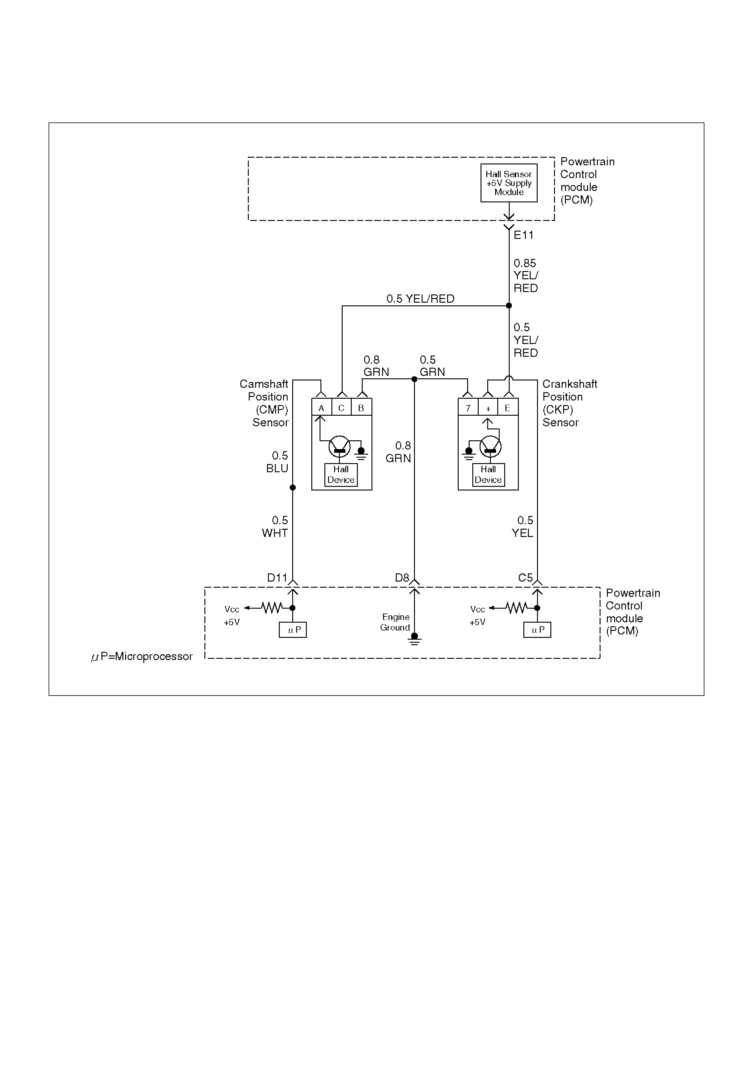
Diagnostic Trouble Code (DTC) P0336 58X Reference Signal Circuit
D06RW032
Circuit Description
The 58X reference signal is produced by the crankshaft
position (CKP) sensor. During one crankshaft
revolution, 58 crankshaft pulses will be produced. The
powertrain control module (PCM) uses the 58X
reference signal to calculate engine RPM and
crankshaft position. The PCM constantly monitors the
number of pulses on the 58X reference circuit and
compares them to the number of camshaft position
(CMP) signal pulses being received. If the PCM
receives an incorrect number of pulses on the 58X
reference circuit, DTC P0336 will set.
Conditions for Setting the DTC
• Engine is running.
• Extra or missing pulse is detected between
consecutive 58X reference pulses.
• Above condition is detected in 10 of 100 crankshaft
rotations.
Action Taken When the DTC Sets
• The PCM will illuminate the malfunction indicator
lamp (MIL) after the second consecutive trip in which
the fault is detected.
• The PCM will store conditions which were present
when the DTC was set as Freeze Frame and in the
Failure Records data.
Conditions for Clearing the MIL/DTC
• DTC P0336 can be cleared by using Tech 2 “Clear
Info” function or by disconnecting the PCM battery
feed.

Diagnostic Aids
An intermittent may be caused by a poor connection,
rubbed-through wire insulation or a wire broken inside
the insulation. Check for:
•Poor connection - Inspect the PCM harness and
connectors for improper mating, broken locks,
improperly formed or damaged terminals, and poor
terminal-to-wire connection.
•Damaged harness – Inspect the wiring harness for
damage. If the harness appears to be OK,
disconnect the PCM, turn the ignition on and observe
a voltmeter connected to the 58X reference circuit at
the PCM harness connector while moving connectors
and wiring harnesses related to the ICM. A change
in voltage will indicate the location of the fault.
Reviewing the Failure Records vehicle mileage since
the diagnostic test last failed may help determine how
often the condition that caused the DTC to be set
occurs. This may assist in diagnosing the condition.
DTC P0336 – 58X Reference Signal Circuit
StepActionValue(s)YesNo
1 Was the “On-Board Diagnostic (OBD) System Check”
performed?—Go to Step 2
Go to OBD
System Check
2 Attempt to start the engine.
Does the engine start?
—Go to Step 3
Go to “Engine
Cranks But Will
Not Run” chart
3 1.Review and record Failure Records information.
2.Clear DTC P0336.
3.Start the engine and idle for 1 minute.
4.Observe DTCs.
Is DTC P0336 set?—Go to Step 4
Refer to
Diagnostic Aids
4 1.Disconnect the PCM and CKP sensor.
2.Check for an open or a short to ground in the 58X
reference circuit between the CKP sensor
connector and the PCM harness connector.
3.If a problem is found, repair as necessary.
Was a problem found?—Verify repairGo to Step 5
5 1.Reconnect the PCM and CKP sensor.
2.Connect a DVM to measure voltage on the 58X
reference circuit at the PCM connector.
3.Observe the voltage while cranking the engine.
Is the voltage near the specified value?2.5 VGo to Step 8 Go to Step 6
6 Check the connections at the CKP sensor and replace
the terminals if necessary.
Did any terminals require replacement?—Verify repairGo to Step 7
7 Replace the CKP sensor. Use caution to avoid any
hot oil that may drip out.
Is the action complete?—Verify repair—
8 Check connections at the PCM and replace the
terminals if necessary.
Did any terminals require replacement?—Verify repairGo to Step 9
9 Replace the PCM.
Important: The replacement PCM must be
programmed. Refer to Sections OC1 Service
Programming System and 11A1 6VE1 Immobiliser.
Is the action complete? — Verify repair —

Diagnostic Trouble Code (DTC) P0337 CKP Sensor Circuit Low Frequency
D06RW032
Circuit Description
The 58X reference signal is produced by the crankshaft
position (CKP) sensor. During one crankshaft
revolution, 58 crankshaft reference pulses will be
produced. The powertrain control module (PCM) uses
the 58X reference signal to calculate engine RPM and
crankshaft position. The PCM constantly monitors the
number of pulses on the 58X reference circuit and
compares them to the number of camshaft position
(CMP) signal pulses being received. If the PCM does
not receive pulses on the 58X reference circuit, DTC
P0337 will set.
Conditions for Setting the DTC
• No camshaft position (CMP) sensor DTCs are set.
• Engine cranking.
• Crankshaft position (CKP) sensor signal is not
present between two cam pulses.
• CKP reference pulse is not detected within 8 CMP
pulses.
Action Taken When the DTC Sets
• The PCM will illuminate the malfunction indicator
lamp (MIL) after the second consecutive trip in which
the fault is detected.
• The PCM will store conditions which were present
when the DTC was set as Freeze Frame and in the
Failure Records data.
Conditions for Clearing the MIL/DTC
• DTC P0337 can be cleared by using Tech 2 “Clear
Info” function or by disconnecting the PCM battery
feed.

Diagnostic Aids
An intermittent may be caused by a poor connection,
rubbed-through wire insulation or a wire broken inside
the insulation. Check for:
•Poor connection – Inspect the PCM harness and
connectors for improper mating, broken locks,
improperly formed or damaged terminals, and poor
terminal-to-wire connection.
•Damaged harness – Inspect the wiring harness for
damage. If the harness appears to be OK,
disconnect the PCM, turn the ignition on and observe
a voltmeter connected to the 58X reference circuit at
the PCM harness connector while moving connectors
and wiring harnesses related to the ICM. A change in
voltage will indicate the location of the fault.
Reviewing the Failure Records vehicle mileage since
the diagnostic test last failed may help determine how
often the condition that caused the DTC to be set
occurs. This may assist in diagnosing the condition.
DTC P0337 – CKP Sensor Circuit Low Frequency
StepActionValue(s)YesNo
1 Was the “On-Board Diagnostic (OBD) System Check”
performed? — Go to Step 2
Go to OBD
System Check
2 Attempt to start the engine.
Does the engine start? — Go to Step 3 Go to Chart 3
3 1. Review and record Failure Records information.
2. Clear DTC P0337.
3. Start the engine and idle for 1 minute.
4. Observe DTCs.
Is DTC P0337 set? — Go to Step 4
Refer to
Diagnostic Aid
4 1. Disconnect the CKP sensor.
2. Ignition “ON.”
3. Using a DVM, verify that 5 V reference and ground
are being supplied at the sensor connector (PCM
side).
Are 4-6 volts and ground available at the sensor? — Go to Step 7 Go to Step 5
5 1. Ignition “ON.”
2. With a DVM, backprobe the PCM connector 5 V
reference and ground connections.
Are 5 V reference and ground available at the PCM? — Go to Step 6 Go to Step 11
6 Check 5 V reference or ground between the CKP
sensor and PCM and repair the open circuit, short to
ground or short to voltage.
Is the action complete? Verify repair —
7 1. Ignition “OFF.”
2. Disconnect the PCM and CKP sensor.
3. Check for an open or a short to ground in the 58X
reference circuit between the CKP sensor
connector and the PCM harness connector.
4. If a problem is found, repair as necessary.
Was a problem found? — Verify repair Go to Step 8
8 1. Reconnect the PCM and CKP sensor.
2. Connect a DVM to measure voltage on the 58X
reference circuit at the PCM connector.
3. Observe the voltage while cranking the engine.
Is the voltage near the specified value? — Go to Step 11 Go to Step 9
9 Check the connections at the CKP sensor and replace
the terminals if necessary.
Did any terminals require replacement? 2.5 V Verify repair Go to Step 10
10 Replace the CKP sensor. Use caution and avoid hot
oil that may drip out.
Is the action complete? — Verify repair —

11 Check the connections at the PCM and replace the
terminals if necessary.
Did any terminals require replacement?—Verify repair Go to Step 12
12 Replace the PCM.
Important: The replacement PCM must be
programmed. Refer to Sections OC1 Service
Programming System and 11A1 6VE1 Immobiliser.
Is the action complete? — Verify repair —
Step Action Value(s) Yes No

Diagnostic Trouble Code (DTC) P0341 CMP Sensor Circuit Performance
D06RW032
Circuit Description
The CMP signal is produced by the camshaft position
(CMP) sensor pulses when the engine is running and
crankshaft position (CKP) sync pulses are also being
received. The powertrain control module (PCM) uses
the CMP signal pulses to initiate sequential fuel
injection. The PCM constantly monitors the number of
pulses on the CMP signal circuit and compares the
number of CMP pulses to the number of 58X reference
pulses received. If the PCM receives an incorrect
number of pulses on the CMP reference circuit, DTC
P0341 will set and the PCM will initiate injector
sequence without the CMP signal with a one in six
chance that injector sequence is correct. The engine
will continue to start and run normally, although the
misfire diagnostic will be affected if a misfiring condition
occurs.
Conditions for Setting the DTC
• The engine is running (1X CMP reference pulses are
being received).
• The CMP sensor signal is not detected at the correct
interval every 6 cylinders.
• Above condition fails for 100 occurrences within 200
test samples.
Action Taken When the DTC Sets
• The PCM will illuminate the malfunction indicator
lamp (MIL) after the second consecutive trip in which
the fault is detected.
• The PCM will initiate the injector sequence without
the CMP signal with a one in six chance that the
injector sequence is correct.

• The PCM will store conditions which were present
when the DTC was set as Freeze Frame and in the
Failure Records data.
Conditions for Clearing the MIL/DTC
• DTC P0341 can be cleared by using Tech 2 “Clear
Info” function or by disconnecting the PCM battery
feed.
Diagnostic Aids
An intermittent may be caused by a poor connection,
rubbed-through wire insulation or a wire broken inside
the insulation. Check for:
• Poor connection – Inspect the PCM harness and
connectors for improper mating, broken locks,
improperly formed or damaged terminals, and poor
terminal-to-wire connection.
• Damaged harness – Inspect the wiring harness for
damage. If the harness appears to be OK,
disconnect the PCM, turn the ignition on and observe
a voltmeter connected to the CMP signal circuit at the
PCM harness connector while moving connectors
and wiring harnesses related to the ICM and the CMP
sensor. A change in voltage will indicate the location
of the fault.
Reviewing the Failure Records vehicle mileage since
the diagnostic test last failed may help determine how
often the condition that caused the DTC to be set
occurs. This may assist in diagnosing the condition.
Test Description
Number(s) below refer to the step number(s) on the
Diagnostic Chart.
2. Ensures that the fault is present.
12. Determines whether the fault is being caused by a
missing camshaft magnet or a faulty sensor. The
voltage measured in this step should read around 4
volts, toggling to near 0 volts when the CMP sensor
interfaces with the camshaft magnet.

DTC P0341 – CMP Sensor Circuit Performance
StepActionValue(s)YesNo
1 Was the “On-Board Diagnostic (OBD) System Check”
performed? — Go to Step 2
Go to OBD
System Check
2 1. Ignition “ON.”
2. Review and record Tech 2 Failure Records data.
3. Operate the vehicle within Failure Records
conditions as noted.
4. Using Tech 2, monitor “Specific DTC” info for DTC
P0341 until the DTC P0341 test runs.
5. Note the test result.
Does Tech 2 indicate DTC P0341 failed this ignition? — Go to Step 3
Refer to
Diagnostic Aids
3 1. Disconnect the CMP sensor.
2. Measure the voltage between the sensor feed
circuit and the sensor ground circuit at the CMP
sensor harness connector.
Does the voltage measure near the specified value? 4-6 V Go to Step 4 Go to Step 5
4 Measure the voltage between the CMP sensor signal
circuit and the sensor ground circuit at the CMP
sensor harness connector.
Does the voltage measure near the specified value? 4-6 V Go to Step 11 Go to Step 8
5 If the voltage measured in step 3 was less than 4-6
volts, proceed directly to step 6 without completing
this step.
If the voltage in step 3 was greater than 4-6 V, repair
the short to voltage in the CMP feed circuit.
Is the action complete? — Verify repair —
6 1. Check for poor connections at the camshaft
position sensor.
2. If a problem is found, repair it as necessary.
Was a problem found? — Verify repair Go to Step 7
7 1. Ignition “OFF,” disconnect the PCM and the CMP
sensor.
2. Check the following circuits for an open between
the ignition coil and the CMP sensor:
• The sensor feed circuit.
3. If a problem is found, repair as necessary.
Was a problem found? — Verify repair Go to Step 9
8 1. Ignition “OFF,” disconnect the PCM (leave the
CMP sensor disconnected).
2. Ignition “ON,” check the following circuits:
• The CMP sensor signal circuit for an open or a
short to voltage.
• The CMP sensor input signal circuit for a short
to ground.
3. If a problem is found, repair it as necessary.
Was a problem found? — Verify repair Go to Step 9
9 Check for a short or open in the sensor ground circuit.
Was a problem found? — Verify repair Go to Step 10
10 1. Check for poor connections at the PCM.
2. If a problem is found, repair it as necessary.
Was a problem found? — Verify repair Go to Step 11

11 Backprobe the PCM connector with a DVM to monitor
voltage on the camshaft position input signal circuit
while cranking the engine with the sensor connected.
(Use rubber band, tape, or an assistant to keep the
DVM lead in contact with the sensor terminal during
this test.)
Does the voltage toggle between the specified
values?4-0 VGo to Step 15 Go to Step 12
12 1.Remove the CMP sensor from the engine front
cover (leave the sensor wiring connected).
2.Place a magnet on the CMP sensor.
(If you use a magnet that is too small to cover the face
of the sensor, test on every part of the sensor face
because only a small area will respond to this test.)
Does the DVM display a voltage near the specified
value?0 VGo to Step 13 Go to Step 14
13 Replace the faulty or missing camshaft position
sensor magnet.
Is the action complete?—Verify repair—
14 Replace the camshaft position sensor.
Is the action complete?—Verify repair—
15 Replace the PCM.
Important: The replacement PCM must be
programmed. Refer to Sections OC1 Service
Programming System and 11A1 6VE1 Immobiliser.
Is the action complete? — Verify repair —
Step Action Value(s) Yes No

Diagnostic Trouble Code (DTC) P0342 CMP Sensor Circuit Low
D06RW032
Circuit Description
The CMP signal produced by the camshaft position
(CMP) sensor pulses when the engine is running and
crankshaft position (CKP) sync pulses are also being
received. The hall type CMP sensor and the CKP
sensor share 5 V and ground connections at the
powertrain control module (PCM). The third wire at the
sensor is a signal circuit to the PCM. The PCM uses
the CMP signal pulses to initiate sequential fuel
injection. The PCM constantly monitors the number of
pulses on the CMP signal circuit and compares the
number of CMP pulses to the number of 58X reference
pulses received. If the PCM does not receive pulses on
the CMP reference circuit, DTC P0342 will set and the
PCM will initiate injector sequence without the CMP
signal with a one in six chance that injector sequence is
correct. The engine will continue to start and run
normally, although the misfire diagnostic will be affected
if a misfiring condition occurs.
Conditions for Setting the DTC
• The engine is running.
• The CMP sensor signal is not received by the PCM
once every 6 cylinders.
• The above condition occurs for 10 seconds.
Action Taken When the DTC Sets
• The PCM will illuminate the malfunction indicator
lamp (MIL) after the second consecutive trip in which
the fault is detected.
• The PCM will initiate injector sequence without the
CMP signal with a one in six chance that the injector
sequence is correct.

•The PCM will store conditions which were present
when the DTC was set as Freeze Frame and in the
Failure Records data.
Conditions for Clearing the MIL/DTC
•DTC P0342 can be cleared by using Tech 2 “Clear
Info” function or by disconnecting the PCM battery
feed.
Diagnostic Aids
An intermittent may be caused by a poor connection,
rubbed-through wire insulation or a wire broken inside
the insulation. Check for:
•Poor connection – Inspect the PCM harness and
connectors for improper mating, broken locks,
improperly formed or damaged terminals, and poor
terminal to wire connection.
•Damaged harness – Inspect the wiring harness for
damage. If the harness appears to be OK,
disconnect the PCM, turn the ignition on and observe
a voltmeter connected to the CMP signal circuit at the
PCM harness connector while moving connectors
and wiring harnesses related to the ICM and the CMP
sensor. A change in voltage will indicate the location
of the fault.
Test Description
Number(s) below refer to the step number(s) on the
Diagnostic Chart.
2. Ensures that the fault is present.
14. Determines whether the fault is being caused by a
missing camshaft magnet or a faulty PCM. The
voltage measured in this step should read around 4
volts, toggling to near 0 volts when the CMP sensor
interfaces with the camshaft magnet.
DTC P0342 – CMP Sensor Circuit Low
StepActionValue(s)YesNo
1 Was the “On-Board Diagnostic (OBD) System Check”
performed? — Go to Step 2
Go to OBD
System Check
2 1. Ignition “ON.”
2. Review and record Tech 2 Failure Records data.
3. Operate the vehicle within Failure Records
conditions as noted.
4. Using Tech 2, monitor “Specific DTC” information
for DTC P0342 until the DTC P0342 test runs.
5. Note test result.
Does Tech 2 indicate DTC P0342 failed this ignition? — Go to Step 3
Refer to
Diagnostic Aids
3 1. Ignition “ON.”
2. Disconnect the CMP sensor.
3. Measure the voltage between the sensor feed
circuit and the sensor ground circuit at the CMP
sensor harness connector.
Does the voltage measure near the specified value? 4-6 V Go to Step 7 Go to Step 4
4 1. Ignition “OFF,” disconnect the PCM and the CMP
sensor.
2. Check for poor connections at the camshaft
position sensor.
3. If a problem is found, repair it as necessary.
Was a problem found? — Verify repair Go to Step 5
5 1. Check for poor connections at the PCM.
2. If a problem is found, repair it as necessary.
Was a problem found? — Verify repair Go to Step 6
6 1. Check the following circuits between the PCM and
the CMP sensor:
• The sensor feed circuit. Open or short to
ground?
• The sensor ground circuit. Open or short to
voltage?
2. If a problem is found, repair as necessary.
Was a problem found? — Verify repair —

7 1. Ignition “ON,” engine “OFF.”
2. Measure the voltage between the CMP sensor
signal circuit and the sensor ground circuit at the
CMP sensor harness connector.
Does the voltage measure near the specified value? 4-6 V Go to Step 8 Go to Step 9
8 1. Turn the ignition “OFF.”
2. Disconnect the PCM and connect a DVM to
monitor voltage on the camshaft position signal
circuit at the PCM connector.
3. Ignition “ON.”
4. Monitor the voltage display on the DVM while
repeatedly touching the CMP sensor signal circuit
at the CMP sensor connector with a test light to
ground.
Does the DVM voltage display switch between 0 and
approximately 5 volts when the test light is touched to
the CMP sensor signal circuit? — Go to Step 12 Go to Step 9
9 1. Ignition “OFF.”
2. Leave the PCM disconnected.
3. Ignition “ON.”
4. Probe the camshaft position signal circuit at the
PCM connector with a test light to B+.
5. If the test light is “ON,” locate and repair the short
to ground in the camshaft position input signal
circuit.
Was either circuit shorted to ground? — Verify repair Go to Step 10
10 1. Ignition “OFF.”
2. Leave the PCM disconnected.
3. Ignition “ON.”
4. Probe the camshaft position signal circuit with a
test light to ground.
5. If the test light is “ON,” locate and repair the short
to voltage in the camshaft position input signal
circuit.
Was the test light“ON”? — Verify repair Go to Step 11
11 1. Ignition “OFF,” disconnect the PCM (leave the
CMP sensor disconnected).
2. Ignition “ON,” check the following circuit:
• The CMP sensor signal circuit for an open.
3. If a problem is found, repair it as necessary.
Was a problem found? — Verify repair —
12 1. Ignition “ON.”
2. Remove the CMP sensor from the engine front
cover (leave the sensor wiring connected).
3. Place a magnet on the CMP sensor. If you use a
magnet that is too small to cover the face of the
sensor, test on every part of the sensor face
because only a small area will respond to this test.
Does the DVM display a voltage near the specified
value? 0 V Go to Step 14 Go to Step 13
13 Replace the camshaft position sensor.
Is the action complete? — Verify repair —
Step Action Value(s) Yes No

14 1. Reinstall the CMP sensor to the engine front
cover.
2. Observe the DVM connected to monitor voltage
on the camshaft position signal circuit while
cranking the engine.
Does the voltage toggle between the specified
values? 4-0 V Go to Step 15 Go to Step 16
15 Replace the PCM.
NOTE: The replacement PCM must be programmed.
Refer to Sections OC1 Service Programming System
and 11A1 6VE1 Immobiliser.
Is the action complete? — Verify repair —
16 Replace faulty or missing camshaft magnet.
Is the action complete? — Verify repair —
Step Action Value(s) Yes No
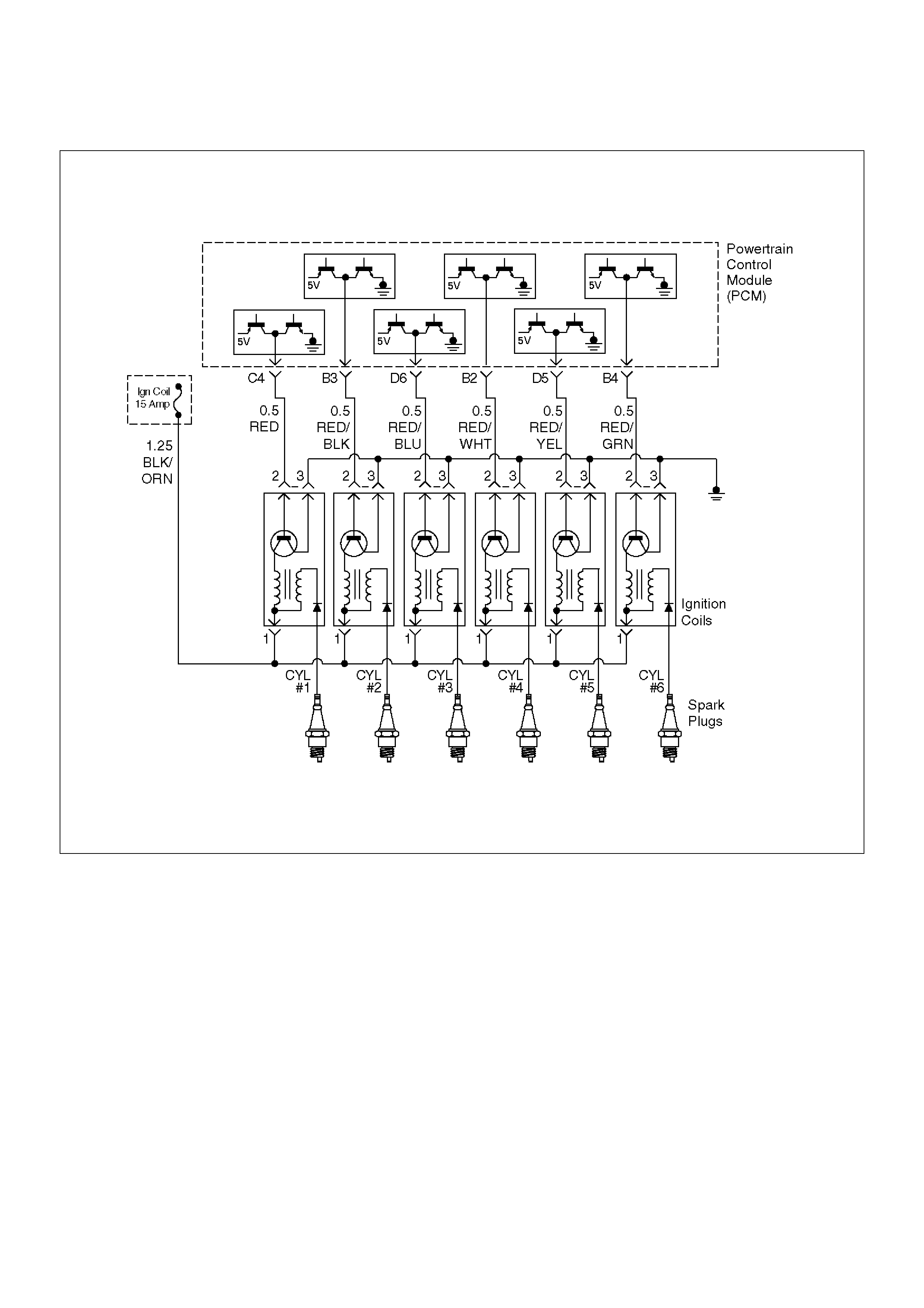
Diagnostic Trouble Code (DTC) P0351 Ignition 1 Control Circuit
D06RW072
Circuit Description
The powertrain control module's (PCM) control circuit 1
provides a zero-volt or a 5-volt output signal to the
ignition coil. The normal voltage on the circuit is zero
volts. When the ignition coil receives the 5-volt signal
from the PCM, it provides a ground path for the B+
supply to the primary side of the number 1 ignition coil.
When the PCM shuts off the 5 volts to the ignition coil,
the ignition coil turns “OFF.” This causes the ignition
coil primary magnetic field to collapse, producing a
voltage in the secondary coil which fires the spark plug.
The circuit between the PCM and ignition coil is
monitored for an open circuit, short to voltage, and short
to ground. When the PCM detects a problem on ignition
control circuit 1, it will set a DTC P0351.
Conditions for Setting the DTC
• The ignition is “ON.”
• The engine is turning, determined by the 58X
crankshaft position input signal.
• The output voltage is not equal to 5 volts when output
is “ON.”
• The output voltage is not equal to 0 volts when output
is “OFF.”
• Twenty test failures occur within 40 samples of
continuous spark events.
Action Taken When the DTC Sets
• The PCM will illuminate the malfunction indicator
lamp (MIL) the first time the fault is detected.
• The PCM will store conditions which were present
when the DTC was set as Freeze Frame and in the
Failure Records data.

Conditions for Clearing the MIL/DTC
•DTC P0351 can be cleared by using Tech 2 “Clear
Info” function or by disconnecting the PCM battery
feed.
Diagnostic Aids
Check for the following conditions:
•Poor connection at PCM – Inspect the harness
connectors for backed-out terminals, improper
mating, broken locks, improperly formed or damaged
terminals, and poor terminal-to-wire connections.
•Damaged harness – Inspect the wiring harness for
damage. If the harness appears to be OK, observe
Tech 2 display related to DTC P0351 while moving
the connector and wiring related to the ignition
system. A change in the display will indicate the
location of the fault.
Reviewing the Failure Records vehicle mileage since
the diagnostic test last failed may help determine how
often the condition that caused the DTC to be set
occurs. This may assist in diagnosing the condition.
DTC P0351 – Ignition 1 Control Circuit
StepActionValue(s)YesNo
1 Was the “On-Board Diagnostic (OBD) System Check”
performed? — Go to Step 2
Go to OBD
System Check
2 1. Ignition “ON,” engine “OFF.”
2. Review and record Tech 2 Failure Records data.
3. Operate the vehicle within Failure Record
conditions as noted.
4. Use Tech 2 to monitor the “Specific DTC”
information for DTC P0351 until the DTC P0351
test runs.
5. Note the test result.
Does Tech 2 indicate DTC P0351 failed this ignition
cycle? — Go to Step 3
Go to
Diagnostic Aids
3 Check for faulty connection at ignition coil.
Was a problem found? — Verify repair Go to Step 4
4 Check for faulty connection at PCM connector.
Was a problem found? — Verify repair Go to Step 5
5 1. Ignition “ON,” engine “OFF.”
2. Back probe the ignition control circuit 1 at the
PCM with a DVM.
Is the voltage near the specified value? 25-55 mV Go to Step 6 Go to Step 9
6 1. Ignition “ON,” engine running.
2. Back probe the ignition control circuit at the PCM
for the cylinder being tested.
Is the voltage in the specified range, rapidly toggling
back and forth to a reading 20-50 mV higher? 100-180 mV Go to Step 7 Go to Step 13
7 1. Ignition “OFF.”
2. Disconnect the 3-pin and 5-pin connectors at the
ignition coil.
3. Check ignition control circuit 1 voltage at the
ignition coil connector while cranking the engine.
Does the voltage measure between the specified
values? 200-1200 mV Go to Step 8 Go to Step 11
8 Replace the ignition coil.
Is the action complete? — Verify repair —
9 1. Ignition “OFF.”
2. Disconnect the PCM and the ignition coil.
3. Check ignition control circuit 1 for short to ground.
Was a problem found? — Verify repair Go to Step 10
10 Check ignition control circuit 1 for short to voltage.
Was a problem found? — Verify repair Go to Step 13

11 Check for an open ignition control circuit 1.
Was the ignition control circuit open?—Go to Step 12 Go to Step 13
12 Repair the open ignition control circuit.
Is the action complete?—Verify repair—
13 Replace the PCM.
Important: The replacement PCM must be
programmed. Refer to Sections OC1 Service
Programming System and 11A1 6VE1 Immobiliser.
Is the action complete? — Verify repair —
Step Action Value(s) Yes No

Diagnostic Trouble Code (DTC) P0352 Ignition 2 Control Circuit
D06RW072
Circuit Description
The powertrain control module's (PCM) control circuit 2
provides a zero-volt or a 5-volt output signal to the
ignition coil. The normal voltage on the circuit is zero
volts. When the ignition coil receives the 5-volt signal
from the PCM, it provides a ground path for the B+
supply to the primary side of the number 2 ignition coil.
When the PCM shuts off the 5 volts to the ignition coil,
the ignition coil turns “OFF.” This causes the ignition
coil primary magnetic field to collapse, producing a
voltage in the secondary coil which fires the spark plug.
The circuit between the PCM and ignition coil is
monitored for an open circuit, short to voltage, and short
to ground. When the PCM detects a problem on ignition
control circuit 2, it will set a DTC P0352.
Conditions for Setting the DTC
• The ignition is “ON.”
• The engine is turning, determined by the 58 X
crankshaft position input signal.
• The output voltage is not equal to 5 volts when output
is “ON.”
• The output voltage is not equal to 0 volts when output
is “OFF.”
• Twenty test failures occur within 40 samples of
continuous spark events.
Action Taken When the DTC Sets
• The PCM will illuminate the malfunction indicator
lamp (MIL) the first time the fault is detected.
• The PCM will store conditions which were present
when the DTC was set as Freeze Frame and in the
Failure Records data.

Conditions for Clearing the MIL/DTC
•DTC P0352 can be cleared by using the Tech 2
“Clear Info” function or by disconnecting the PCM
battery feed.
Diagnostic Aids
Check for the following conditions:
•Poor connection at PCM – Inspect the harness
connectors for backed-out terminals, improper
mating, broken locks, improperly formed or damaged
terminals, and poor terminal-to-wire connections.
•Damaged harness – Inspect the wiring harness for
damage. If the harness appears to be OK, observe
the Tech 2 display related to DTC P0352 while
moving the connector and wiring related to the
ignition system. A change in the display will indicate
the location of the fault.
Reviewing the Failure Records vehicle mileage since
the diagnostic test last failed may help determine how
often the condition that caused the DTC to be set
occurs. This may assist in diagnosing the condition.
DTC P0352 – Ignition 2 Control Circuit
StepActionValue(s)YesNo
1 Was the “On-Board Diagnostic (OBD) System Check”
performed? — Go to Step 2
Go to OBD
System Check
2 1. Ignition “ON,” engine “OFF.”
2. Review and record Tech 2 Failure Records data.
3. Operate the vehicle within Failure Record
conditions as noted.
4. Use a Tech 2 to monitor the “Specific DTC”
information for DTC P0352 until the DTC P0352
test runs.
5. Note the test result.
Does the Tech 2 indicate DTC P0352 failed this
ignition cycle? — Go to Step 3
Go to
Diagnostic Aids
3 Check for faulty connection at ignition coil.
Was a problem found? — Verify repair Go to Step 4
4 Check for faulty connection at PCM connector.
Was a problem found? — Verify repair Go to Step 5
5 1. Ignition “ON,” engine “OFF.”
2. Back probe the ignition control circuit 2 at the
PCM with a DVM .
Is the voltage near the specified value? 25-55 mV Go to Step 6 Go to Step 9
6 1. Ignition “ON,” engine running.
2. Back probe the ignition control circuit at the PCM
for the cylinder being tested.
Is the voltage in the specified range, rapidly toggling
back and forth to a reading 20-50 mV higher? 100-180 mV Go to Step 7 Go to Step 13
7 1. Ignition “OFF.”
2. Disconnect the 3-pin and 5-pin connectors at the
ignition coil.
3. Check ignition control circuit 2 voltage at the
ignition coil connector while cranking the engine
connector.
Does the voltage measure between the specified
values? 200-1200 mV Go to Step 8 Go to Step 11
8 Replace the ignition coil.
Is the action complete? — Verify repair —
9 1. Ignition “OFF.”
2. Disconnect the PCM and the ignition coil.
3. Check ignition control circuit 2 for short to ground.
Was a problem found? — Verify repair Go to Step 10

10 Check ignition control circuit 2 for short to voltage.
Was a problem found?—Verify repairGo to Step 13
11 Check for an open ignition control circuit 1.
Was the ignition control circuit open?—Go to Step 12 Go to Step 13
12 Repair the open ignition control circuit.
Is the action complete?—Verify repair—
13 Replace the PCM.
Important: The replacement PCM must be
programmed. Refer to Sections OC1 Service
Programming System and 11A1 6VE1 Immobiliser.
Is the action complete? — Verify repair —
Step Action Value(s) Yes No

Diagnostic Trouble Code (DTC) P0353 Ignition 3 Control Circuit
D06RW072
Circuit Description
The powertrain control module's (PCM) control circuit 3
provides a zero-volt or a 5-volt output signal to the
ignition coil. The normal voltage on the circuit is zero
volts. When the ignition coil receives the 5-volt signal
from the PCM, it provides a ground path for the B+
supply to the primary side of the number 3 ignition coil.
When the PCM shuts off the 5 volts to the ignition coil,
the ignition coil turns “OFF.” This causes the ignition
coil primary magnetic field to collapse, producing a
voltage in the secondary coil which fires the spark plug.
The circuit between the PCM and ignition coil is
monitored for an open circuit, short to voltage, and short
to ground. When the PCM detects a problem on ignition
control circuit 3, it will set a DTC P0353.
Conditions for Setting the DTC
• The ignition is “ON.”
• The engine is turning, determined by the 58X
crankshaft position input signal.
• The output voltage is not equal to 5 volts when output
is “ON.”
• The output voltage is not equal to 0 volts when output
is “OFF.”
• Twenty test failures occur within 40 samples of
continuous spark events.
Action Taken When the DTC Sets
• The PCM will illuminate the malfunction indicator
lamp (MIL) the first time the fault is detected.
• The PCM will store conditions which were present
when the DTC was set as Freeze Frame and in the
Failure Records data.

Conditions for Clearing the MIL/DTC
•DTC P0353 can be cleared by using the Tech 2
“Clear Info” function or by disconnecting the PCM
battery feed.
Diagnostic Aids
Check for the following conditions:
•Poor connection at PCM – Inspect the harness
connectors for backed-out terminals, improper
mating, broken locks, improperly formed or damaged
terminals, and poor terminal-to-wire connections.
•Damaged harness – Inspect the wiring harness for
damage. If the harness appears to be OK, observe
the Tech 2 display related to DTC P0353 while
moving the connector and wiring related to the
ignition system. A change in the display will indicate
the location of the fault.
Reviewing the Failure Records vehicle mileage since
the diagnostic test last failed may help determine how
often the condition that caused the DTC to be set
occurs. This may assist in diagnosing the condition.
DTC P0353 – Ignition 3 Control Circuit
StepActionValue(s)YesNo
1 Was the “On-Board Diagnostic (OBD) System Check”
performed? — Go to Step 2
Go to OBD
System Check
2 1. Ignition “ON,” engine “OFF.”
2. Review and record Tech 2 Failure Records data.
3. Operate the vehicle within Failure Record
conditions as noted.
4. Use a Tech 2 to monitor the “Specific DTC”
information for DTC P0353 until the DTC P0353
test runs.
5. Note the test result.
Does the Tech 2 indicate DTC P0353 failed this
ignition cycle? — Go to Step 3
Go to
Diagnostic Aids
3 Check for faulty connection at ignition coil.
Was a problem found? — Verify repair Go to Step 4
4 Check for faulty connection at PCM connector.
Was a problem found? — Verify repair Go to Step 5
5 1. Ignition “ON,” engine “OFF.”
2. Back probe the ignition control circuit 3 at the
PCM with a DVM positive lead with the negative
lead to ground.
Is the voltage near the specified value? 25-55 mV Go to Step 6 Go to Step 9
6 1. Ignition “ON,” engine running.
2. Back probe the ignition control circuit at the PCM
for the cylinder being tested.
Is the voltage in the specified range, rapidly toggling
back and forth to a reading 20-50 mV higher? 100-180 mV Go to Step 7 Go to Step 13
7 1. Ignition “OFF.”
2. Disconnect the 3-pin and 5-pin connectors at the
ignition coil.
3. Check ignition control circuit 3 voltage at the
ignition coil connector while cranking the engine.
Does the voltage measure between the specified
values? 200-1200mV Go to Step 8 Go to Step 11
8 Replace the ignition coil.
Is the action complete? — Verify repair —
9 1. Ignition “OFF.”
2. Disconnect the PCM and the ignition coil.
3. Check ignition control circuit 3 for short to ground.
Was a problem found? — Verify repair Go to Step 10

10 Check ignition control circuit 3 for short to voltage.
Was a problem found?—Verify repairGo to Step 13
11 Check for an open ignition control circuit 1.
Was the ignition control circuit open?—Go to Step 12 Go to Step 13
12 Repair the open ignition control circuit.
Is the action complete?—Verify repair—
13 Replace the PCM.
Important: The replacement PCM must be
programmed. Refer to Sections OC1 Service
Programming System and 11A1 6VE1 Immobiliser.
Is the action complete? — Verify repair —
Step Action Value(s) Yes No

Diagnostic Trouble Code (DTC) P0354 Ignition 4 Control Circuit
D06RW072
Circuit Description
The powertrain control module's (PCM) control circuit 4
provides a zero-volt or a 5-volt output signal to the
ignition coil. The normal voltage on the circuit is zero
volts. When the ignition coil receives the 5-volt signal
from the PCM, it provides a ground path for the B+
supply to the primary side of the number 4 ignition coil.
When the PCM shuts off the 5 volts to the ignition coil,
the ignition coil turns “OFF.” This causes the ignition
coil primary magnetic field to collapse, producing a
voltage in the secondary coil which fires the spark plug.
The circuit between the PCM and ignition coil is
monitored for an open circuit, short to voltage, and short
to ground. When the PCM detects a problem on ignition
control circuit 4, it will set a DTC P0354.
Conditions for Setting the DTC
• The ignition is “ON.”
• The engine is turning, determined by the 58X
crankshaft position input signal.
• The output voltage is not equal to 5 volts when output
is “ON.”
• The output voltage is not equal to 0 volts when output
is “OFF.”
• Twenty test failures occur within 40 samples of
continuous spark events.
Action Taken When the DTC Sets
• The PCM will illuminate the malfunction indicator
lamp (MIL) the first time the fault is detected.
• The PCM will store conditions which were present
when the DTC was set as Freeze Frame and in the
Failure Records data.

Conditions for Clearing the MIL/DTC
•DTC P0354 can be cleared by using the Tech 2
“Clear Info” function or by disconnecting the PCM
battery feed.
Diagnostic Aids
Check for the following conditions:
•Poor connection at PCM – Inspect the harness
connectors for backed-out terminals, improper
mating, broken locks, improperly formed or damaged
terminals, and poor terminal-to-wire connections.
•Damaged harness – Inspect the wiring harness for
damage. If the harness appears to be OK, observe
the Tech 2 display related to DTC P0354 while
moving the connector and wiring related to the
ignition system. A change in the display will indicate
the location of the fault.
Reviewing the Failure Records vehicle mileage since
the diagnostic test last failed may help determine how
often the condition that caused the DTC to be set
occurs. This may assist in diagnosing the condition.
DTC P0354 – Ignition 4 Control Circuit
StepActionValue(s)YesNo
1 Was the “On-Board Diagnostic (OBD) System Check”
performed? — Go to Step 2
Go to OBD
System Check
2 1. Ignition “ON,” engine “OFF.”
2. Review and record Tech 2 Failure Records data.
3. Operate the vehicle within Failure Record
conditions as noted.
4. Use a Tech 2 to monitor the “Specific DTC”
information for DTC P0354 until the DTC P0354
test runs.
5. Note the test result.
Does the Tech 2 indicate DTC P0354 failed this
ignition cycle? — Go to Step 3
Go to
Diagnostic Aids
3 Check for faulty connection at ignition coil.
Was a problem found? — Verify repair Go to Step 4
4 Check for faulty connection at PCM connector.
Was a problem found? — Verify repair Go to Step 5
5 1. Ignition “ON,” engine “OFF.”
2. Back probe the ignition control circuit 4 at the
PCM with a DVM positive lead with the negative
lead to ground.
Is the voltage near the specified value? 25-55 mV Go to Step 6 Go to Step 9
6 1. Ignition “ON,” engine running.
2. Back probe the ignition control circuit at the PCM
for the cylinder being tested.
Is the voltage in the specified range, rapidly toggling
back and forth to a reading 20-50 mV higher? 100-180 mV Go to Step 7 Go to Step 13
7 1. Ignition “OFF.”
2. Disconnect the 3-pin and 5-pin connectors at the
ignition coil.
3. Check ignition control circuit 4 voltage at the
ignition coil connector while cranking the engine.
Does the voltage measure between the specified
values? 200-1200 mV Go to Step 8 Go to Step 11
8 Replace the ignition coil.
Is the action complete? — Verify repair —
9 1. Ignition “OFF.”
2. Disconnect the PCM and the ignition coil.
3. Check ignition control circuit 4 for short to ground.
Was a problem found? — Verify repair Go to Step 10

10 Check ignition control circuit 4 for short to voltage.
Was a problem found?—Verify repairGo to Step 13
11 Check for an open ignition control circuit 1.
Was the ignition control circuit open?—Go to Step 12 Go to Step 13
12 Repair the open in ignition control circuit.
Is the action complete?—Verify repair—
13 Replace the PCM.
Important: The replacement PCM must be
programmed. Refer to Sections OC1 Service
Programming System and 11A1 6VE1 Immobiliser.
Is the action complete? — Verify repair —
Step Action Value(s) Yes No

Diagnostic Trouble Code (DTC) P0355 Ignition 5 Control Circuit
D06RW072
Circuit Description
The powertrain control module's (PCM) control circuit 5
provides a zero-volt or a 5-volt output signal to the
ignition coil. The normal voltage on the circuit is zero
volts. When the ignition coil receives the 5-volt signal
from the PCM, it provides a ground path for the B+
supply to the primary side of the number 5 ignition coil.
When the PCM shuts off the 5 volts to the ignition coil,
the ignition coil turns “OFF.” This causes the ignition
coil primary magnetic field to collapse, producing a
voltage in the secondary coil which fires the spark plug.
The circuit between the PCM and ignition coil is
monitored for an open circuit, short to voltage, and short
to ground. When the PCM detects a problem on ignition
control circuit 5, it will set a DTC P0355.
Conditions for Setting the DTC
• The ignition is “ON.”
• The engine is turning, determined by the 58X
crankshaft position input signal.
• The output voltage is not equal to 5 volts when output
is “ON.”
• The output voltage is not equal to 0 volts when output
is “OFF.”
• Twenty test failures occur within 40 samples of
continuous spark events.
Action Taken When the DTC Sets
• The PCM will illuminate the malfunction indicator
lamp (MIL) the first time the fault is detected.
• The PCM will store conditions which were present
when the DTC was set as Freeze Frame and in the
Failure Records data.

Conditions for Clearing the MIL/DTC
•DTC P0355 can be cleared by using the Tech 2
“Clear Info” function or by disconnecting the PCM
battery feed.
Diagnostic Aids
Check for the following conditions:
•Poor connection at PCM – Inspect the harness
connectors for backed-out terminals, improper
mating, broken locks, improperly formed or damaged
terminals, and poor terminal-to-wire connections.
•Damaged harness – Inspect the wiring harness for
damage. If the harness appears to be OK, observe
the Tech 2 display related to DTC P0355 while
moving the connector and wiring related to the
ignition system. A change in the display will indicate
the location of the fault.
Reviewing the Failure Records vehicle mileage since
the diagnostic test last failed may help determine how
often the condition that caused the DTC to be set
occurs. This may assist in diagnosing the condition.
DTC P0355 – Ignition 5 Control Circuit
StepActionValue(s)YesNo
1 Was the “On-Board Diagnostic (OBD) System Check”
performed? — Go to Step 2
Go to OBD
System Check
2 1. Ignition “ON,” engine “OFF.”
2. Review and record Tech 2 Failure Records data.
3. Operate the vehicle within Failure Record
conditions as noted.
4. Use a Tech 2 to monitor the “Specific DTC”
information for DTC P0355 until the DTC P0355
test runs.
5. Note the test result.
Does the Tech 2 indicate DTC P0355 failed this
ignition cycle? — Go to Step 3
Go to
Diagnostic Aids
3 Check for faulty connection at ignition coil.
Was a problem found? — Verify repair Go to Step 4
4 Check for faulty connection at PCM connector.
Was a problem found? — Verify repair Go to Step 5
5 1. Ignition “ON,” engine “OFF.”
2. Back probe the ignition control circuit 5 at the
PCM with a DVM positive lead with the negative
lead to ground.
Is the voltage near the specified value? 25-55 mV Go to Step 6 Go to Step 9
6 1. Ignition “ON,” engine running.
2. Back probe the ignition control circuit at the PCM
for the cylinder being tested.
Is the voltage in the specified range, rapidly toggling
back and forth to a reading 20-50 mV higher? 100-180 mV Go to Step 7 Go to Step 13
7 1. Ignition “OFF.”
2. Disconnect the 3-pin and 5-pin connectors at the
ignition coil.
3. Check ignition control circuit 5 voltage at the
ignition coil connector while cranking the engine.
Does the voltage measure between the specified
values? 200-1200 mV Go to Step 8 Go to Step 11
8 Replace the ignition coil.
Is the action complete? — Verify repair —
9 1. Ignition “OFF.”
2. Disconnect the PCM and the ignition coil.
3. Check ignition control circuit 5 for short to ground.
Was a problem found? — Verify repair Go to Step 10

10 Check ignition control circuit 5 for short to voltage.
Was a problem found?—Verify repairGo to Step 13
11 Check for an open ignition control circuit 1.
Was the ignition control circuit open?—Go to Step 12 Go to Step 13
12 Repair the open ignition control circuit.
Is the action complete?—Verify repair—
13 Replace the PCM.
Important: The replacement PCM must be
programmed. Refer to Sections OC1 Service
Programming System and 11A1 6VE1 Immobiliser.
Is the action complete? — Verify repair —
Step Action Value(s) Yes No

Diagnostic Trouble Code (DTC) P0356 Ignition 6 Control Circuit
D06RW072
Circuit Description
The powertrain control module's (PCM) control circuit 6
provides a zero-volt or a 5-volt output signal to the
ignition coil. The normal voltage on the circuit is zero
volts. When the ignition coil receives the 5-volt signal
from the PCM, it provides a ground path for the B+
supply to the primary side of the number 6 ignition coil.
When the PCM shuts off the 5 volts to the ignition coil,
the ignition coil turns “OFF.” This causes the ignition
coil primary magnetic field to collapse, producing a
voltage in the secondary coil which fires the spark plug.
The circuit between the PCM and ignition coil is
monitored for an open circuit, short to voltage, and short
to ground. When the PCM detects a problem on ignition
control circuit 6, it will set a DTC P0356.
Conditions for Setting the DTC
• The ignition is “ON.”
• The engine is turning, determined by the 58X
crankshaft position input signal.
• The output voltage is not equal to 5 volts when output
is “ON.”
• The output voltage is not equal to 0 volts when output
is “OFF.”
• Twenty test failures occur within 40 samples of
continuous circuit monitoring.
Action Taken When the DTC Sets
• The PCM will illuminate the malfunction indicator
lamp (MIL) the first time the fault is detected.
• The PCM will store conditions which were present
when the DTC was set as Freeze Frame and in the
Failure Records data.

Conditions for Clearing the MIL/DTC
•DTC P0356 can be cleared by using the Tech 2
“Clear Info” function or by disconnecting the PCM
battery feed.
Diagnostic Aids
Check for the following conditions:
•Poor connection at PCM – Inspect the harness
connectors for backed-out terminals, improper
mating, broken locks, improperly formed or damaged
terminals, and poor terminal-to-wire connections.
•Damaged harness – Inspect the wiring harness for
damage. If the harness appears to be OK, observe
the Tech 2 display related to DTC P0356 while
moving the connector and wiring related to the
ignition system. A change in the display will indicate
the location of the fault.
Reviewing the Failure Records vehicle mileage since
the diagnostic test last failed may help determine how
often the condition that caused the DTC to be set
occurs. This may assist in diagnosing the condition.
DTC P0356 – Ignition 6 Control Circuit
StepActionValue(s)YesNo
1 Was the “On-Board Diagnostic (OBD) System Check”
performed? — Go to Step 2
Go to OBD
System Check
2 1. Ignition “ON,” engine “OFF.”
2. Review and record Tech 2 Failure Records data.
3. Operate the vehicle within Failure Record
conditions as noted.
4. Use a Tech 2 to monitor the “Specific DTC”
information for DTC P0356 until the DTC P0356
test runs.
5. Note the test result.
Does the Tech 2 indicate DTC P0356 failed this
ignition cycle? — Go to Step 3
Go to
Diagnostic Aids
3 Check for faulty connection at ignition coil.
Was a problem found? — Verify repair Go to Step 4
4 Check for faulty connection at PCM connector.
Was a problem found? — Verify repair Go to Step 5
5 1. Ignition “ON,” engine “OFF.”
2. Back probe the ignition control circuit 6 at the
PCM with a DVM positive lead with the negative
lead to ground.
Is the voltage near the specified value? 25-55 mV Go to Step 6 Go to Step 9
6 1. Ignition “ON,” engine running.
2. Back probe the ignition control circuit at the PCM
for the cylinder being tested.
Is the voltage in the specified range, rapidly toggling
back and forth to a reading 20-50 mV higher? 100-180 mV Go to Step 7 Go to Step 13
7 1. Ignition “OFF.”
2. Disconnect the 3-pin and 5-pin connectors at the
ignition coil.
3. Check ignition control circuit 6 voltage at the
ignition coil connector while cranking the engine.
Does the voltage measure between the specified
values? 200-1200 mV Go to Step 8 Go to Step 11
8 Replace the ignition coil.
Is the action complete? — Verify repair —
9 1. Ignition “OFF.”
2. Disconnect the PCM and the ignition coil.
3. Check ignition control circuit 6 for short to ground.
Was a problem found? — Verify repair Go to Step 10

10 Check ignition control circuit 6 for short to voltage.
Was a problem found?—Verify repairGo to Step 13
11 Check for an open ignition control circuit 1.
Was the ignition control circuit open?—Go to Step 12 Go to Step 13
12 Repair the open ignition control circuit.
Is the action complete?—Verify repair—
13 Replace the PCM.
Important: The replacement PCM must be
programmed. Refer to Sections OC1 Service
Programming System and 11A1 6VE1 Immobiliser.
Is the action complete? — Verify repair —
Step Action Value(s) Yes No

Diagnostic Trouble Code (DTC) P0402 EGR Pintle Crank Error
D06RW106
Circuit Description
The powertrain control module (PCM) monitors the
EGR valve pintle position input to ensure that the valve
responds properly to commands from the PCM, and to
detect a fault if pintle position is stuck open. If the PCM
detects a pintle position signal indicates more than
21.5% and more than for 625 msec during cranking, the
PCM will set DTC P0402.
Conditions for Setting the DTC
• Ignition voltage is between 11 and 16 volts.
• Intake Air temp is more than 3°C
• At Engine revolution less than 600 RPM, EGR pintle
position indicates more than 21.5% and more than for
625 msecs.
Action Taken When the DTC Sets
• The PCM will illuminate the malfunction indicator
lamp (MIL) after the second consecutive trip in which
the fault is detected.
• The PCM will store conditions which were present
when the DTC was set as Freeze Frame and in
Failure Records data.
Conditions for Clearing the MIL/DTC
• DTC P0402 can be cleared by using Tech 2 “Clear
Info” function or by disconnecting the PCM battery
feed.
Diagnostic Aids
Check for the following conditions:
• Foreign material on EGR valve between pintle and
seat may cause EGR stuck open. Inspect foreign
material in EGR valve.
• Excessive carbon deposit may cause unsmooth
operation of EGR valve shaft. Inspect carbon deposit
and clean up inside of carbon deposit.
• Poor connection or damaged harness–inspect the
wiring harness for damage If the harness appears to
be OK, observe the EGR actual position display on
Tech 2 while moving connectors and wiring
harnesses related to EGR valve. A change in the
display will indicate the location of the fault.
NOTE: If the EGR valve shows signs of excessive heat,
check the exhaust system for blockage (possibly a
plugged catalytic converter) using the“Restricted
Exhaust System Check”.

DTC P0402 – EGR Pintle Crank Open Error
StepActionValue(s)YesNo
1 Was the “On-Board Diagnostic (OBD) System Check”
performed? — Go to Step 2
Go to OBD
System Check
2 1. Ignition“ON”, engine“OFF”, review and record
Tech 2 Failure Records data.
2. Operate the vehicle within Failure Records
conditions as noted.
3. Using Tech 2, monitor “Specific DTC” info for DTC
P0402 until the DTC P0402 test runs. Note the
result.
Does Tech 2 indicates DTC P0402 failed this ignition? — Go to Step 3
Refer to
Diagnostic Aids
3 1. Disconnect the EGR valve harness connector.
2. Inspect the EGR valve and connectors for
damaged pin or terminals.
Were there any damaged pins or terminals? — Go to Step 4 Go to Step 5
4 Repair the damaged pin or terminal.
Is the action complete? — Verify repair —
5 1. Remove EGR valve from Engine.
2. Inspect EGR valve whether there is any foreign
material between seat and pintle.
Was any foreign material in EGR valve? — Go to Step 6 Go to Step 7
6 1. Remove EGR valve foreign material from EGR
valve and clean up inside.
2. Visually inspect damage of pintle and seat, which
leakage may occur.
Was there any severe damage which affects function? — Go to Step 7
Verify repair
Go to Step 8
7 1. Reconnect.
2. Ignition“OFF”.
3. Install Tech 2.
4. Run the engine at idle.
5. On Tech-II, select special function for EGR.
6. Use the “UP” arrow to increase the EGR from 0%
to 40%.
Did EGR work properly? — — Go to Step 8
8 Replace the EGR valve.
Does DTC P0402 still fail “DTC” test on Tech 2? — Go to Step 9 Verify repair
9 Replace the EGR valve.
Is the action complete? — Verify repair —
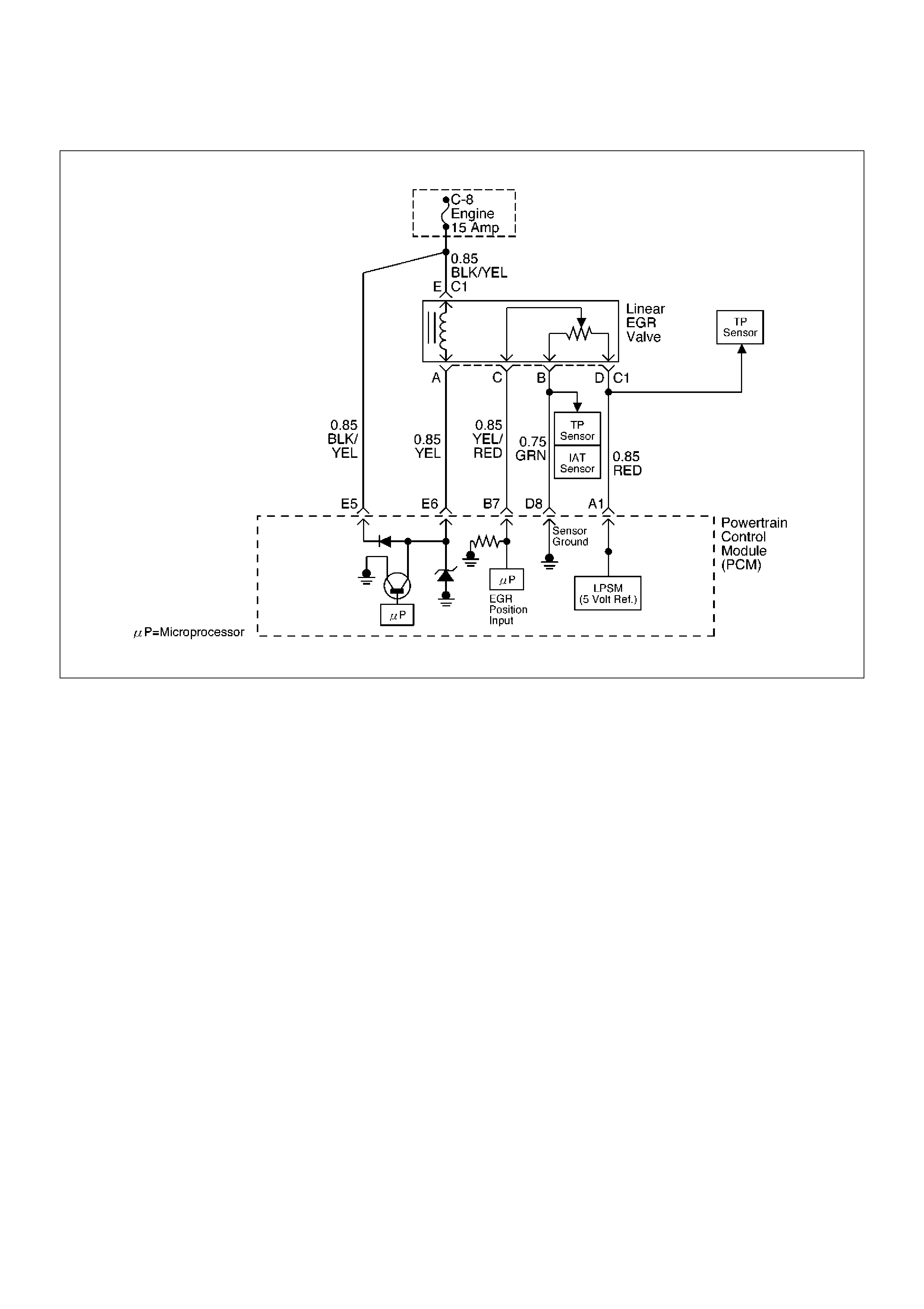
Diagnostic Trouble Code (DTC) P0404 EGR Open Stuck
D06RW106
Circuit Description
The powertrain control module (PCM) monitors the
EGR valve pintle position input to ensure that the valve
responds properly to commands from the PCM, and to
detect a fault if pintle position is different from
commanded position. If the PCM detects a pintle
position signal indicates more than 15 points different
between current and commanded and more than 15
seconds, the PCM will set DTC P0404.
Conditions for Setting the DTC
• Ignition voltage is between 11 and 16 volts.
• Intake Air temp is more than 3°C.
• Desire EGR position is more than 0.
• The difference between desired EGR and current
EGR is less than 3%.
• Difference EGR pintle position between current and
commanded position becomes more than 15% and
last more than 15 seconds, and this condition meets
three times in a trip. Then it trigger, the PCM lights
on.
Action Taken When the DTC Sets
• The PCM will illuminate the malfunction indicator
lamp (MIL) as soon as failure detected after
consecutive 2nd trip in which the fault is detected.
• The PCM will store conditions which were present
when the DTC was set as Freeze Frame and in
Failure Records data.
Conditions for Clearing the MIL/DTC
• DTC P0404 can be cleared by using Tech 2 “Clear
Info” function or by disconnecting the PCM battery
feed.
Diagnostic Aids
Check for the following conditions:
• Excessive carbon deposit on EGR valve shaft may
cause EGR stuck open or unsmooth operation.
Those carbon deposit may occur by unusual port
operation. Clean up carbon may make smooth
function of EGR valve.
• Poor connection or damaged harness – Inspect the
wiring harness for damage. If the harness appears to
be OK, observe the EGR actual position display on
Tech 2 while moving connectors and wiring
harnesses related to EGR valve. A change in the
display will indicate the location of the fault.
DTC P0404 – E GR Open Stuck

StepActionValue(s)YesNo
1 Was the “On-Board Diagnostic (OBD) System Check”
performed?—Go to Step 2
Go to OBD
System Check
2 1.Ignition “ON,” engine“OFF”, review and record
Tech 2 Failure Records Data.
2.Operate the vehicle within Failure Records
conditions as noted.
3.Using Tech 2, monitor “Specific DTC” info for DTC
P0404 until the DTC P0404 test runs. Note the
result.
Does Tech 2 indicates DTC P0404 failed this ignition?—Go to Step 3
Refer to
Diagnostic Aids
3 1.Disconnect the EGR valve harness connector.
2.Inspect the EGR valve and connectors for
damaged pin or terminals.
Were there any damaged pins or terminals?—Go to Step 4 Go to Step 5
4 Repair the damaged pin or terminal.
—Verify repair
Is the action
complete?
5 1.Remove EGR valve from Engine.
2.Inspect EGR valve whether there is any
excessive carbon deposit on EGR shaft.
Was excessive carbon deposit 0n EGR valve shaft?—Go to Step 6 Go to Step 7
6 1.Clean up EGR valve shaft and inside of EGR
valve.
2.Visually inspect damage of pintle and seat
whether there is bent, leakage may occur.
Was there any severe damage which affects function?—Go to Step 8
Verify repair
Go to Step 7
7 1.Reconnect.
2.Ignition“OFF”.
3.Install Tech 2.
4.Run the engine at idle.
5.On Tech 2, select F3:Misc. Test; F2:EGR.
6.Use the “UP” arrow to increase the EGR from 0%
to 40%.
Did EGR work properly?——Go to Step 8
8 Replace the EGR valve.
Does DTC P0404 still fail “DTC” test on Tech 2?—Go to Step 9 Verify repair
9 Replace the PCM.
Important: The replacement PCM must be
programmed. Refer to Sections OC1 Service
Programming System and 11A1 6VE1 Immobiliser.
Is the action complete? — Verify repair —

Diagnostic Trouble Code (DTC) P0405 EGR Low Voltage
D06RW106
Circuit Description
The powertrain control module (PCM) monitors the
EGR valve pintle position input to ensure that the valve
responds properly to command from the PCM. If
current pintle position voltage indicates less than 0.1 V
and last more than 10 seconds, then the PCM will set
DTC P0405.
Conditions for Setting the DTC
• Ignition voltage is between 11 and 16 volts.
• EGR pintle position output voltage is less than 0.1
volt and last more than 10 sec. Action taken when
the DTC sets.
Action Taken When the DTC Sets
• The PCM will illuminate the malfunction indicator
lamp (MIL) as soon as failure detected.
• The PCM will store conditions which were present
when the DTC was set as Freeze Frame and in
Failure Records data.
Conditions for Clearing the MIL/DTC
• DTC P0405 can be cleared by using Tech 2 “Clear
Info” function or by disconnecting the PCM battery
feed.
Diagnostic Aids
Check for the following conditions:
• Poor connection or damaged harness – Inspect the
wiring harness for damage. If the harness appears to
be OK, observe the EGR actual position display on
Tech 2 while moving connectors and wiring
harnesses related to EGR valve. A change in the
display will indicate the location of the fault.

DTC P0405 – EGR Low Volt
StepActionValue(s)YesNo
1 Was the “On-Board Diagnostic (OBD) System Check”
performed? — Go to Step 2
Go to OBD
System Check
2 1. Ignition “ON,” engine“OFF”, review and record
Tech 2 Failure Records Data.
2. Operate the vehicle within Failure Records
conditions as noted.
3. Using Tech 2, monitor “DTC” info for DTC P0405
until the DTC P0405 test runs. Note the result.
Does Tech 2 indicates DTC P0405 failed this ignition? — Go to Step 3
Refer to
Diagnostic Aids
3 1. Disconnect the EGR valve harness connector.
2. Inspect the EGR valve and connectors for
damaged pin or terminals.
Were there any damaged pins or terminals? — Go to Step 4 Go to Step 5
4 Repair the damaged pin or terminal.
Is the action complete? — Verify repair —
5 1. Disconnect the EGR harness connector.
2. Ignition“ON”.
3. At the EGR valve, use a DVM to check the voltage
at the 5 volt reference wire (RED) and ground (B).
Did the DVM indicate the specified value? 4–6 V Go to Step 6 Go to Step 7
6 1. Disconnect the EGR harness connector.
2. Measure resistance between terminal B and D.
Was resistance in range? 5–5.5 KWGo to Step 10 Go to Step 17
7 1. Ignition“ON”.
2. At the PCM connector, backprobe with a DVM at
the 5 volt reference for the EGR valve.
Did the DVM indicate the specified value? 4–6 V Go to Step 8 Go to Step 9
8 Repair the open 5 volt reference circuit.
Is the action complete? — Verify repair —
9 Repair the damaged sensor ground wire.
Is the action complete? — Verify repair —
10 1. Disconnect the EGR harness
2. Use an ohmmeter to measure between the pintle
position pin and the sensor ground pin on the
EGR valve.
NOTE: J-35616 Connector Test Adapter Kit may be
useful for gaining access to the recessed pins on the
valve.
Was the ohmmeter reading approximately equal to the
specified value? 1 to 1.25 KWGo to Step 11 Go to Step 17
11 1. Ignition“ON”.
2. Backprobe with a DVM to measure voltage at
EGR valve pintle position pin and sensor ground
pin.
Was voltage in range?
Less than
0.1V Go to Step 17 Go to Step 12
12 1. Ignition“ON”.
2. Backprobe with a DVM to measure voltage at
PCM sensor ground pin and pintle position pin.
Was voltage in range?
Less than
0.1V Go to Step 13 Go to Step 18

13 1.Ignition“OFF”.
2.Disconnect the EGR harness.
3.Check short circuit between EGR pintle position
circuit and EGR ground circuit.
Was any short circuit?—Go to Step 14 Go to Step 18
14 Locate and repair the short to ground in the pintle
position circuit
Is the action complete?—Verify repair—
15 1.Ignition“OFF”.
2.Disconnect the PCM.
3.Ignition“ON”.
4.Measure the voltage between the EGR pintle
position circuit and ground.
Is the measured voltage near the specified value?
Less than
0.1VGo to Step 17 Go to Step 16
16 Check for a short circuit between other wires and the
pintle position circuit
Was any short circuit?—
Repair short
circuit
Verify repairGo to Step 17
17 Replace the EGR valve.
Does DTC P1404 still fail “specific DTC test on Tech
2?—Go to Step 18 Verify repair
18 Examine the PCM pin and terminal connection.
Was there a damaged terminal?—Go to Step 4 Go to Step 19
19 Replace the PCM.
Important: The replacement PCM must be
programmed. Refer to Sections OC1 Service
Programming System and 11A1 6VE1 Immobiliser.
Is the action complete? — Verify repair —
Step Action Value(s) Yes No

Diagnostic Trouble Code (DTC) P0406 EGR High Voltage
D06RW106
Circuit Description
The powertrain control module (PCM) monitors the
EGR valve pintle position input to ensure that the valve
responds properly to command from the PCM. If
current pintle position voltage indicates more than 4.8 V
and last more than 10 seconds, then the PCM will set
DTC P0406.
Conditions for Setting the DTC
• Ignition voltage is between 11 and 16 volts.
• EGR pintle position output voltage is more than 4.8
volt and last more than 10 sec.
Action Taken When the DTC Sets
• The PCM will illuminate the malfunction indicator
lamp (MIL) as soon as failure detected.
• The PCM will store conditions which were present
when the DTC was set as Freeze Frame and in
Failure Records data.
Conditions for Clearing the MIL/DTC
• DTC P0404 can be cleared by using Tech 2 “Clear
Info” function or by disconnecting the PCM battery
feed.
Diagnostic Aids
Check for the following conditions:
• Poor connection or damaged harness – Inspect the
wiring harness for damage. If the harness appears to
be OK, observe the EGR actual position display on
Tech 2 while moving connectors and wiring
harnesses related to EGR valve. A change in the
display will indicate the location of the fault.

DTC P0406 – EGR High Voltage
StepActionValue(s)YesNo
1 Was the “On-Board Diagnostic (OBD) System Check”
performed? — Go to Step 2
Go to OBD
System Check
2 1. Ignition “ON,” engine“OFF”, review and record
Tech 2 Failure Records Data.
2. Operate the vehicle within Failure Records
conditions as noted.
3. Using Tech 2, monitor “DTC” info for DTC P0406
until the DTC P0406 test runs. Note the result.
Does Tech 2 indicates DTC P0406 failed this ignition? — Go to Step 3
Refer to
Diagnostic Aids
3 1. Disconnect the EGR valve harness connector.
2. Inspect the EGR valve and connectors for
damaged pin or terminals.
Were there any damaged pins or terminals? — Go to Step 4 Go to Step 5
4 Repair the damaged pin or terminal.
Is the action complete? — Verify repair
Is the action
complete?
5 1. Disconnect the EGR harness connector.
2. Ignition“ON”.
3. At the EGR valve, use a DVM to check the voltage
at the 5 volt reference wire (RED).
Did the DVM indicate the specified value? 4–6V Go to Step 8 Go to Step 6
6 1. Ignition“ON”.
2. At the PCM connector, backprobe with a DVM at
the 5 volt reference for the EGR valve.
Did the DVM indicate the specified value? 4–6 V Go to Step 7 Go to Step 16
7 Repair the open 5 volt reference circuit
Is the action complete? — Verify repair —
8 1. Ignition “OFF”
2. Disconnect the EGR harness.
3. Use a DVM to check for an resistance between D
(5 V reference) and B (Sensor Ground) at EGR
sensor terminals.
NOTE: J-35616 Connector Test Adapter Kit may be
useful for gaining access to the recessed pins on the
valve.
Was there measured resistance in range? 5 to 5 KWGo to Step 9 Go to Step 15
9 1. Ignition“OFF”.
2. Disconnect the EGR harness.
3. Use a DVM to check for an resistance between B
and C at EGR sensor terminal.
Was there open circuit? — Go to Step 15 Go to Step 10
10 1. Ignition“OFF”.
2. Disconnect the EGR harness at PCM connector.
3. Use a DVM to check for shorted wire between A1
and B7.
Was there shorted wire? — Go to Step 14 Go to Step 11
11 1. Ignition“ON”.
2. Use a DVM to backprobe at terminal C of EGR
valve for voltage.
Was measured voltage more than 4.8V?
more than
4.8V Go to Step 12 Go to Step 12

12 1.Ignition“ON”.
2.Stay the EGR harness connected.
3.Check voltage by backproving at PCM B7
terminal.
Was voltage more than 4.8V?4.8VGo to Step 16 Go to Step 13
13 1.Locate short circuit at EGR harness between RED
to RED or GREEN, RED to YEL.
2.Replace EGR harness.
Is the action complete?—Verify repair—
14 Replace EGR harness.
Is the action complete?—Verify repair—
15 Replace the EGR valve.
Does DTC P1404 still fail “specific DTC test on Tech
2?—Go to Step 16 Verify repair
16 Replace the PCM.
Important: The replacement PCM must be
programmed. Refer to Sections OC1 Service
Programming System and 11A1 6VE1 Immobiliser.
Is the action complete? — Verify repair —
Step Action Value(s) Yes No
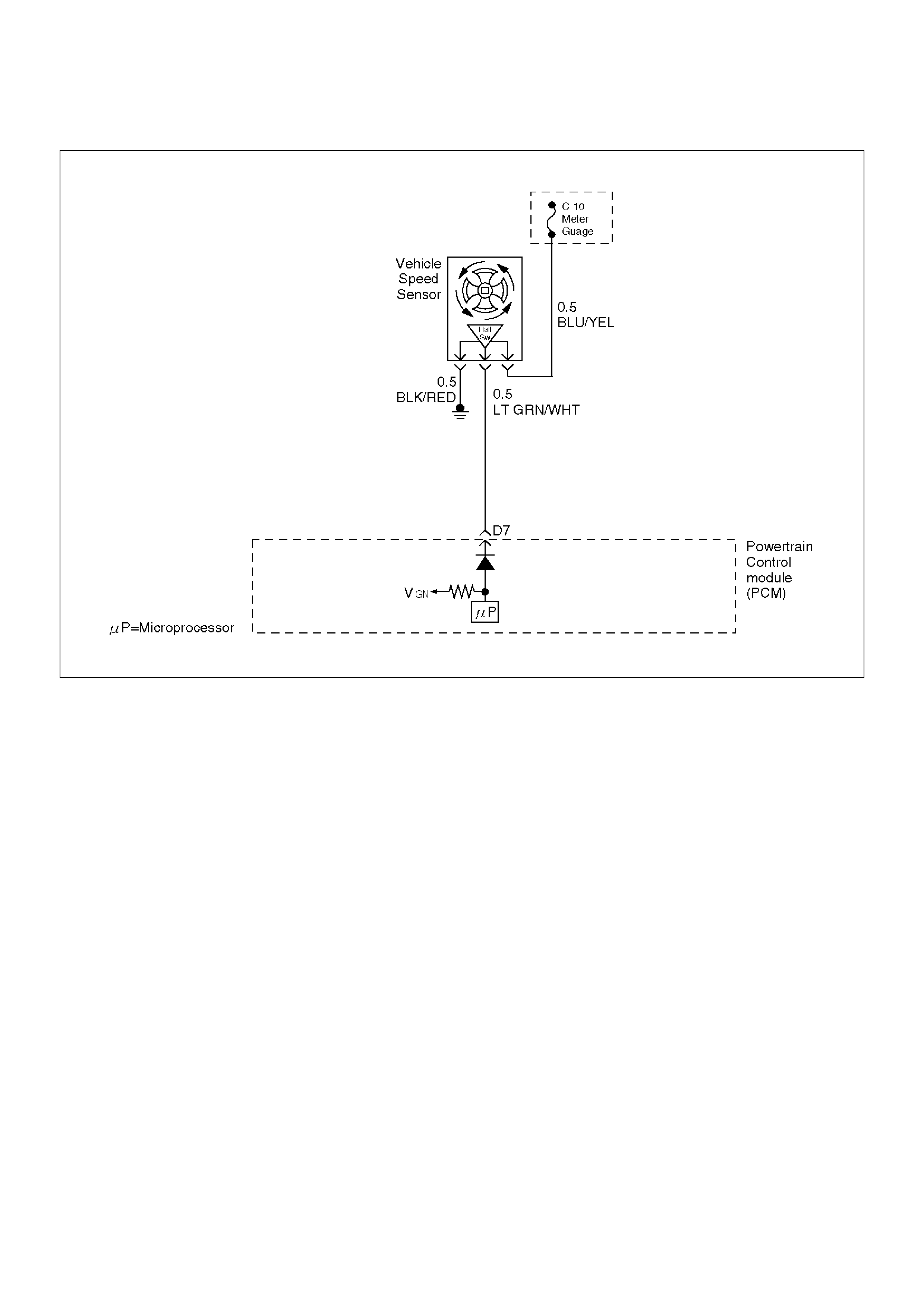
Diagnostic Trouble Code (DTC) P0502 VSS Circuit Low Input
D06RW019
Circuit Description
The vehicle speed sensor has a magnet rotated by the
transmission output shaft. Attached to the sensor is a
hall effect circuit the interacts with the magnetic field
treated by the rotating magnet. A 12-volt operating
supply for the speed sensor hall circuit is supplied from
the meter fuse. The VSS pulses to ground the 9-volt
signal sent from the powertrain control module (PCM)
on the reference circuit. The PCM interprets vehicle
speed by the number of pulses to ground per second on
the reference circuit.
Conditions for Setting the DTC
• Engine is running.
• Engine coolant temperature is above 60°C (140°F).
• Engine speed is between 1800 RPM and 2500 RPM.
• Throttle angle is between 10% and 40%.
• Engine load is greater than 50 kPa.
• MAP sensor indicates greater than 50 kPa manifold
pressure.
• PCM detects no VSS signal for 12.5 seconds over a
period of 25 seconds.
Action Taken When the DTC Sets
• The PCM will illuminate the malfunction indicator
lamp (MIL) the first time the fault is detected.
• The PCM will store conditions which were present
when the DTC was set as Freeze Frame and in the
Failure Records data.
Conditions for Clearing the MIL/DTC
• DTC P0502 can be cleared by using the Tech 2
“Clear Info” function or by disconnecting the PCM
battery feed.
Test Description
Number(s) below refer to the step number(s) on the
Diagnostic Chart.
10. To avoid backprobing the VSS and possibly
damaging a seal or terminal, the VSS output can be
tested at the point where the transmission harness
connects to the engine harness. Power and ground
are applied by jumpers to the VSS through the
connectors which are located just in front of the air
cleaner assembly. The VSS signal is monitored with
a DVM as the rear driveshaft turns. The wheels can
be turned to rotate the driveshaft, or in
2-wheels-drive vehicles the driveshaft can be turned
directly.

12. The speedometer-to-PCM VSS signal wire is
spliced to a wire leading to the cruise control
module. If a short to ground or voltage is indicated
between the PCM and speedometer, it could be on
the cruise control circuit if the vehicle is equipped
with cruise control.
DTC P0502 – VSS Circuit Low Input
StepActionValue(s)YesNo
1 Was the “On-Board Diagnostic (OBD) System Check”
performed? — Go to Step 2
Go to OBD
System Check
2 Does the speedometer work? — Go to Step 10 Go to Step 3
3 1. Disconnect the VSS connector.
2. Ignition “ON.”
3. Using a test light to battery +, probe the connector
ground wire.
Did the light illuminate? — Go to Step 5 Go to Step 4
4 Repair the sensor ground.
Is the action complete? — Verify repair —
5 1. Ignition “ON,” sensor disconnected.
2. Using a DVM, measure at the VSS connector
between ground and voltage supply.
Was the measurement near the specified value?
Battery
voltage Go to Step 7 Go to Step 6
6 Repair the open or short to ground which may have
blown the meter fuse.
Is the action complete? — Verify repair —
7 1. Ignition “ON,” VSS disconnected.
2. Using a DVM, measure at the VSS connector
between ground and the wire from the
speedometer.
Was the measurement near the specified value? 7.5-8 V Go to Step 9 Go to Step 8
8 Check for an open or short circuit between the
speedometer and the VSS.
Was an open or short circuit located? — Verify repair Go to Step 9
9 Replace the speedometer.
Is the action complete? — Verify repair —

10 1.Ignition “OFF.”
2.Disconnect the MAF sensor and remove the air
cleaner assembly and filter element to gain
access to the 16-way black connector located
immediately to the rear of the left front headlamp.
The connector attaches the VSS wires from the
transmission harness to the left-side engine
harness.
3.Disconnect the black 16-way connector.
4.Select a terminal adapter from kit J 35616 that can
be used with a jumper to supply B+ to the blue
wire with a yellow tracer (transmission side of the
connector).
5.Use another terminal adapter to attach a voltmeter
to the light-green wire with a while tracer (next to
the wire in the previous step.)
6.Disconnect the blue connector next to the black
16-way connector, and locate the black/red tracer
wire at one corner of the blue connector. The
black/red wire is the VSS ground. Use a terminal
adapter to attach a jumper to ground to the black/
red VSS ground wire at the transmission side of
the blue connector.
7.Raise the rear wheels off the ground with
transmission in neutral.
Does the DVM toggle back and forth between 0.6 V
and 10 V as the wheels (and driveshaft) are rotated?—Go to Step 11 Go to Step 12
11 Replace the VSS.
Is the action complete?—Verify repair—
12 Check for an open or short between the PCM and the
speedometer.
Was a problem found?—Verify repairGo to Step 13
13 Replace the PCM.
Important: The replacement PCM must be
programmed. Refer to Sections OC1 Service
Programming System and 11A1 6VE1 Immobiliser.
Is the action complete? — Verify repair —
Step Action Value(s) Yes No
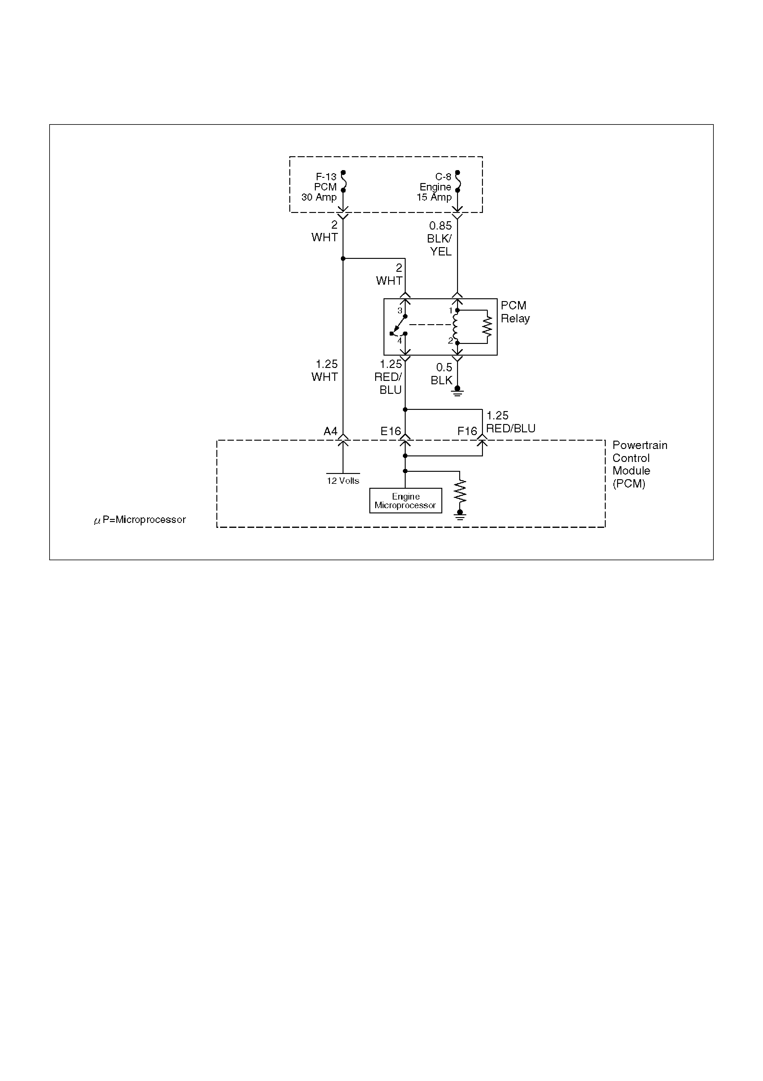
Diagnostic Trouble Code (DTC) P0562 System Voltage Low
D06RW020
Circuit Description
The powertrain control module (PCM) monitors the
system voltage on the ignition feed terminal to the PCM.
A system voltage DTC will set whenever the voltage is
below a calibrated value.
Conditions for Setting the DTC
• Ignition “ON.”
• System voltage is below 11.5 volts for 15 minutes.
Action Taken When the DTC Sets
• The PCM will not illuminate the malfunction indicator
lamp (MIL).
• The PCM will store as Failure Records conditions
which were present when the DTC was set. This
information will not be stored as Freeze Frame data.
Conditions for Clearing the MIL/DTC
• A history DTC P0562 will clear after 40 consecutive
warm-up cycles have occurred without a fault.
• DTC P0562 can be cleared by using the Tech 2
“Clear Info” function or by disconnecting the PCM
battery feed.
Diagnostic Aids
If the DTC sets when an accessory is operated, check
for a poor connection or excessive current draw.

DTC P0562 – System Voltage Low
StepActionValue(s)YesNo
1 Was the “On-Board Diagnostic (OBD) System Check”
performed?—Go to Step 2
Go to OBD
System Check
2 Using a Tech 2, measure the battery voltage at the
battery.
Is the battery voltage greater than the specified value?11.5 VGo to Step 3
Charge battery,
then go to Step
3
3 1.Using a Tech 2.
2.Select “Ignition Volts” on the Tech 2.
3.Start the engine and raise the engine speed to the
specified value.
4.Load the electrical system by turning on the
headlights, high blower, etc.
Is the ignition voltage approximately equal to the
specified value?
2000 RPM
12.8-14.1 VGo to Step 4
Go to Starting/
Charging
4 1.Ignition “OFF.”
2.Disconnect the PCM connector at the PCM.
3.Using a DVM, measure the battery voltage at the
PCM connector A-4.
Is it approximately equal to battery voltage?—
Check for
excessive
current draw
with ignition
“OFF,” engine
“OFF.”Go to Step 5
5 1.Check for faulty connections at the PCM harness
terminals.
2.Repair as necessary.
Was a repair necessary?—Verify repairGo to Step 6
6 Check for an open battery feed circuit to the PCM.
Is the action complete?—Verify repairGo to Step 7
7 Replace the PCM.
Important: The replacement PCM must be
programmed. Refer to Sections OC1 Service
Programming System and 11A1 6VE1 Immobiliser.
Is the action complete? — Verify repair —

Diagnostic Trouble Code (DTC) P0563 System Voltage High
Circuit Description
The powertrain control module (PCM) monitors the
system voltage on the ignition feed terminals to the
PCM. A system voltage DTC will set whenever the
voltage is above a calibrated value.
Conditions for Setting the DTC
•Ignition “ON.”
•System voltage is above 16 volts for 15 minutes.
Action Taken When the DTC Sets
•The PCM will not illuminate the malfunction indicator
lamp (MIL).
•The PCM will store as Failure Records only
conditions which were present when the DTC was
set. This information will not be stored as Freeze
Frame data.
Conditions for Clearing the MIL/DTC
•A history DTC P0563 will clear after 40 consecutive
warm-up cycles have occurred without a fault.
•DTC P0563 can be cleared by using the Tech 2
“Clear Info” function or by disconnecting the PCM
battery feed.
Diagnostic Aids
If the DTC sets when an accessory is operated, check
for a poor connection or excessive current draw.
DTC P0563 – System Voltage High
StepActionValue(s)YesNo
1 Was the “ON-Board Diagnostic (OBD) System Check”
performed?—Go to Step 2
Go to OBD
System Check
2 Using a Tech 2, measure the battery voltage at the
battery.
Is the battery voltage less than the specified value?11.5 VGo to Step 3 Go to Step 4
3 1.Charge the battery and clean the battery
terminals.
2.Clean the battery ground cable connection if
corrosion is indicated.
Is the battery voltage less than the specified value?11.5 VReplace batteryGo to Step 4
4 1.Turn “OFF” all the accessories.
2.Install a Tech 2.
3.Select the ignition voltage parameter on the Tech
2.
4.Start the engine and raise the engine RPM to the
specified value.
Is the voltage more than 2.5 volts greater than the
measurement taken in step 2 or 3?2000 RPM
Go to Starting/
ChargingGo to Step 5
5 Replace the PCM.
Important: The replacement PCM must be
programmed. Refer to UBS 98 model year
Immobiliser Workshop Manual.
Is the action complete? — Verify repair —

Diagnostic Trouble Code (DTC) P0601 PCM Memory
Circuit Description
The powertrain control module (PCM) used in this
vehicle utilizes an electrically erasable programmable
read-only memory (EEPROM). The EEPROM contains
program information and the calibrations required for
engine, transmission, and powertrain diagnostics
operation.
Unlike the PROM used in past applications, the
EEPROM is not replaceable.
Conditions for Setting the DTC
•The PCM detects an internal program fault (check
sum error).
Action Taken When the DTC Sets
•The PCM will not illuminate the malfunction indicator
lamp (MIL).
•The PCM will store conditions which were present
when the DTC was set in the Failure Records data
only.
Conditions for Clearing the MIL/DTC
•DTC P0601 can be cleared by using the Tech 2
“Clear Info” function or by disconnecting the PCM
battery feed.
Diagnostic Aids
•DTC P0601 indicates that the contents of the
EEPROM have changed since the PCM was
programmed. The only possible repair is PCM
replacement.
DTC P0601 – PCM Memory
StepActionValue(s)YesNo
1 —
Was the “On-Board Diagnostic (OBD) System Check”
performed?—Go to Step 2
Go to OBD
System Check
2 Replace the PCM.
Important: The replacement PCM must be
programmed. Refer to Sections OC1 Service
Programming System and 11A1 6VE1 Immobiliser.
Is the action complete? — Verify repair —

Diagnostic Trouble Code (DTC) P1154 HO2S Circuit Transition Time Ratio Bank 2 Sensor 1
060RW190
Circuit Description
The powertrain control module (PCM) monitors the
heated oxygen sensor (HO2S) activity for 90 seconds
after “closed loop” and stoichiometric operation have
been enabled. During the monitor period the PCM
counts the number of times that the HO2S responds
from rich-to-lean and from lean-to-rich and adds the
amount of time it took to complete all transitions. With
this information, an average time for all transitions can
be determined. The PCM then divides the rich-to-lean
average by the lean-to-rich average to obtain a ratio. If
the HO2S transition time ratio is not within this range,
DTC P1154 will be set, indicating that the oxygen
sensor is not responding as expected to changes in
exhaust oxygen content.
Conditions for Setting the DTC
• No related DTCs.
• Engine coolant temperature (ETC) is above 50°C
(122°F) for automatic transmission; 75°C (167°F) for
manual transmission.
• The engine is operating in “closed loop.”
• The engine has been running at least one minute.
• Canister purge duty cycle is greater than 2%.
• Engine speed is between 1500 RPM and 3000 RPM.
• Mass air flow is between 9 g/second and 42 g/
second.
• Above conditions are present for a 3-second
monitoring period.
• 90 seconds after “closed loop” and stoichiometric
operation have been enabled, Bank 2 HO2S 1
transition ratio between lean to rich and rich to lean is
less than 0.44 or greater than 3.8.
Action Taken When the DTC Sets
• The PCM will illuminate the malfunction indicator
lamp (MIL) after the second consecutive trip in which
the fault is detected.
• "Open loop" fuel control will be in effect.
• The PCM will store conditions which were present
when the DTC was set as Freeze Frame and in the
Failure Records data.
Conditions for Clearing the MIL/DTC
• DTC P1154 can be cleared by using Tech 2 “Clear
Info” function or by disconnecting the PCM battery
feed.
Diagnostic Aids
A multifunction in the HO2S heater ignition feed or
ground circuit may cause a DTC P1154 to set. Check

HO2S heater circuitry for intermittent faults or poor
connections. If connections and wiring are OK and DTC
P1154 continues to set, replace the Bank 2 HO2S 1.
Reviewing the Failure Records vehicle mileage since
the diagnostic test last failed may help determine how
often the condition that caused the DTC to be set
occurs. This may assist in diagnosing the condition.
Test Description
Number(s) below refer to the step number(s) on the
Diagnostic Chart.
3. A condition that affects other heated oxygen sensors
indicates probable contamination. To avoid
damaging replacement sensors, correct the
condition which caused the contamination before
replacing the affected sensors.
5. This step checks for conditions which may cause the
heated oxygen sensor to appear faulty. Correct any
of the described conditions if present.
8. To avoid damaging replacement sensors, correct the
condition which caused the contamination before
replacing the affected sensors.
DTC P1154 – HO2S Transition Time Ratio Bank 2 Sensor 1
StepActionValue(s)YesNo
1 Was the “On-Board Diagnostic (OBD) System Check”
performed?—Go to Step 2
Go to OBD
System Check
2 Important: If any other DTCs are set (except P1133
and/or P1134), refer to those DTCs before proceeding
with this diagnostic chart.
1. Idle the engine at operating temperature.
2. Operate the vehicle within parameters specified
under “Conditions for Setting the DTC” criteria
included in Diagnostic Support.
3. Using a Tech 2, monitor “Specific DTC” info for
DTC P1154 until the DTC P1154 test runs.
Note the test result.
Does Tech 2 indicate DTC failed this ignition? — Go to Step 3
Refer to
Diagnostic Aids
3 Did Tech 2 also indicate P1133, and/or P1134 test
failed? — Go to Step 17 Go to Step 4
4 Check for leaks at the pipe joints.
Are the joints leaking? — Go to Step 5 Go to Step 6
5 Tighten the U-bolt nuts at the leaking joints.
Is your action complete? — Go to Step 2 —
6 Check for gaskets that are damaged or improperly
installed.
Are there damaged or misaligned gaskets? — Go to Step 7 Go to Step 8
7 1. Replace the damaged gaskets.
2. Align the connections.
3. Tighten the connections.
Is your action complete? — Go to Step 2 —
8 Check for loose exhaust flange connections.
Are the flange connections loose? — Go to Step 9 Go to Step 10
9 Tighten the stud nuts or bolts to specifications.
Is your action complete? — Go to Step 2 —
10 Check for burned or corroded exhaust pipes.
Are the exhaust pipes burned or corroded? — Go to Step 11 Go to Step 12
11 Replace the exhaust pipes, as required.
Is your action complete? — Go to Step 2 —
12 Check for leaks at the exhaust manifold.
Are there leaks at the exhaust manifold? — Go to Step 13 Go to Step 14
13 Tighten the bolts to specifications or replace the
manifold if necessary.
Is your action complete? — Go to Step 2 —

14 Visually/physically inspect the following items:
•Ensure that the Bank 2 HO2S 1 is securely
installed.
•Check for corrosion on terminals.
•Check terminal tension (at Bank 2 HO2S 1 and at
the PCM).
•Check for damaged wiring.
Was a problem found in any of the above areas?—Go to Step 18 Go to Step 15
15 1.Disconnect Bank 1 HO2S 1.
2.Ignition “ON.”
3.Using a DVM at the PCM side of the HO2S 1
connector, measure the voltage between the high
signal circuit and ground.
Also measure the voltage between the low signal
circuit and ground.
Are both voltages in the specified range?3-4VGo to Step 16 Go to Step 19
16 1.With Bank 1 HO2S 1 disconnected, jumper the
high and low (PCM side) signal circuits to ground.
2.Ignition “ON.”
3.Using Tech 2, monitor the Bank 2 HO2S 1 voltage.
Does the scan too indicate less than 10 mV and
immediately return to about 450 mV when the jumper
is removed?—Go to Step 21 Go to Step 22
17 Replace affected heated oxygen sensors.
NOTE: Before replacing sensors, the cause of the
contamination must be determined and corrected.
•Fuel contamination.
•Use of improper RTV sealant.
•Engine oil/coolant consumption.
Is the action complete?—Verify repair—
18 Repair condition as necessary.
Is the action complete?—Verify repair—
19 Check for faulty PCM connections or terminal
damage.
Is the action complete?—Verify repairGo to Step 20
20 Repair open, short or grounded signal circuit.
Is the action complete?—Verify repair—
21 Replace Bank 2 HO2S 1.
Is the action complete?—Verify repair—
22 Replace the PCM.
Important: The replacement PCM must be
programmed. Refer to Sections OC1 Service
Programming System and 11A1 6VE1 Immobiliser.
Is the action complete? — Verify repair —
Step Action Value(s) Yes No
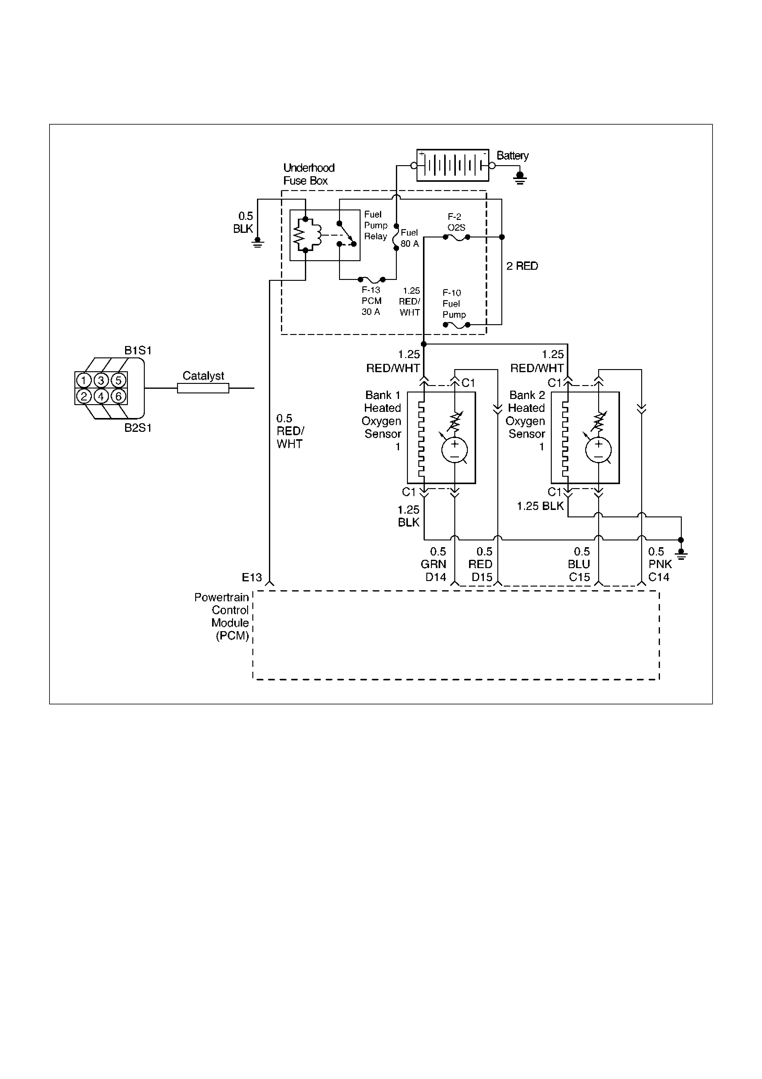
Diagnostic Trouble Code (DTC) P1171 Fuel System Lean During Acceleration
060RW193-1
Circuit Description
The powertrain control module (PCM) internal circuitry
can identify if the vehicle fuel system is capable of
supplying adequate amounts of fuel during heavy
acceleration (power enrichment). The PCM monitors
the voltage of the oxygen sensor during power
enrichment. When a power enrichment mode of
operation is requested during “closed loop” operation
(by heavy acceleration), the PCM will provide more fuel
to the engine. Under these conditions the PCM should
detect a “rich” condition (high oxygen sensor voltage).
If this “rich” exhaust is not detected at this time, a DTC
P1171 will set. A plugged fuel filter, restricted fuel line,
restricted in-tank filter or defective fuel pump can
prevent adequate amounts of fuel from being supplied
during power enrichment mode.
Conditions for Setting the DTC
• No related DTCs.
• Engine is operating in “closed loop power
enrichment” mode for 3 seconds.
• Engine coolant temperature is above 60°C (140°F).
• While in “power enrichment” mode the oxygen sensor
voltage remains below 400 mV for 3 seconds.
Action Taken When the DTC Sets
• The PCM will illuminate the malfunction indicator
lamp (MIL) the first the fault is detected.
• The PCM will store conditions which were present
when the DTC was set as Freeze Frame and in the
Failure Records data.

Conditions for Clearing the MIL/DTC
•DTC P1171 can be cleared by using Tech 2 “Clear
Info” function or by disconnecting the PCM battery
feed.
Diagnostic Aids
•A restricted fuel filter or fuel line, restricted in-tank
filter, or a defective fuel pomp may supply adequate
amounts of fuel at idle, but may not be able to supply
enough fuel during heavy acceleration.
•Water or alcohol in the fuel may cause low HO2S
voltage during acceleration.
•Check for faulty or plugged fuel injector(s).
•Check for low fuel.
Test Description
Number(s) below refer to the step number(s) on the
Diagnostic Chart.
4. When the engine is idling or at steady cruise, the
HO2S voltage should vary from between
approximately 100 mV to 900 mV. It is possible to
measure a satisfactory fuel pressure at idle even
though the pressure may drop at high flow
requirements. It may be necessary to watch fuel
pressure at high engine load.
5. Wrap a shop towel around the fuel pressure
connector to absorb any small amount of fuel
leakage that may occur when installing gauge.
Ignition “ON,” pump pressure should be 280-320
kPa.
DTC P1171 – Fuel System Lean During Acceleration
StepActionValue(s)YesNo
1 Was the “On-Board Diagnostic (OBD) System Check”
performed? — Go to Step 2
Go to OBD
System Check
2 Are any component-related DTCs set?
—
Go to
component
DTC charts Go to Step 3
3 1. Check the vehicle's fuel tank for an adequate
amount of fuel.
2. Add fuel to the vehicle's fuel tank if the tank is
almost empty.
Was fuel added to the vehicle's fuel tank? — Go to Step 4 Go to Step 5
4 1. Place the transmission in park.
2. Using Tech 2, observe HO2S 1 voltage while
running warm engine 75°C-95°C (167°F-203°F) at
1200 RPM.
3. HO2S 1 voltage should vary within the specified
range.
4. Quickly open the throttle halfway for a few
seconds.
Did the voltage suddenly rise toward the high end of
the specified range? 100-900mV Go to Chart A-7 Go to Step 5
5 1. Disconnect the fuel pump relay and crank the
engine to relieve the fuel pressure.
2. Install the fuel pressure gauge.
3. Start the engine and idle at normal operating
temperature.
4. Disconnect the vacuum line going to the fuel
pressure regulator.
With the engine running, is the fuel pressure within the
specified range?
280-325 kPa
(41-46 psi)
Go to OBD
System Check Go to Step 6
6 Check for restricted fuel lines or restricted in-line filter.
Was a problem found? — Verify repair Go to Step 7

7 1. Ignition “OFF.”
2. Remove the fuel pump relay and replace it with a
fused jumper which will connect the relay's battery
terminal to the terminal leading to the fuel pump
fuse.
3. While the fuel pump is operating, use pliers to
slowly close the return line (do not exceed the first
specified value).
Using the pliers to restrict the return line, can the fuel
pressure be manipulated to exceed the second
specified value?
414kPa
(60psi)
325kPa
(46psi)
Go to
Diagnostic Aids Go to Step 8
8 Check for:
• Faulty fuel pump
• Restricted fuel pump strainer (sock)
• Incorrect fuel pump
• Incorrect fuel being used
• Hot fuel
Is the action complete? — Verify repair —
Step Action Value(s) Yes No

Diagnostic Trouble Code (DTC) P1380 ABS Rough Road ABS System Fault
Circuit Description
The powertrain control module (PCM) monitors ABS
fault signal. When PCM receives fault signal, PCM will
set DTC P1380.
Conditions for Setting the DTC
•Vehicle speed is more than 5 mph.
•Load is less than 99%.
•Engine revolution is less than 6250 rpm.
•PCM receives ABS fault signals from ABS unit.
•Ignition on.
•Misfire DTCs exist.
•100 test failures within 120 test samples.
Action Taken When the DTC Sets
•The PCM will store DTC 1380 only, no MIL turn on.
Conditions for Clearing the MIL/DTC
•A history DTC P1380 will clear after 40 consecutive
warm-up cycles have occurred without a fault.
•DTC 1380 can be cleared by using Tech-2 or
disconnecting the PCM battery feed.
Diagnostic Aids
Check for the following conditions:
•PCM and ABS communication line short circuit to
other line may cause faulty signal. Inspect
communication line.
•Follow ABS ECU diagnosis procedure, refer to ABS
procedure page.
DTC P1380 – ABS Rough Road ABS System Fault
StepActionValue(s)YesNo
1 Was the “On-Board Diagnostic (OBD) System Check”
performed?—Go to Step 2
Go to OBD
System Check
2 1.Ignition “ON,” engine“OFF”, review and record
Tech 2 Failure Records Data.
2.Operate the vehicle within Failure Records
conditions as noted.
3.Using a Tech 2, monitor “Specific DTC” info for
DTC P1380 and Misfire DTCs until the DTC
P1380 and Misfire DTCs test runs. Note the result.
Does the Tech 2 indicates DTC P1380 and Misfire
DTCs failed this ignition?—
Refer to
ABS
diagnosis
After inspect
ABS, unit
repeat Step
2
Still problem
exists, go to
Step 3
Clear DTC by
Tech 2
3 Check short circuit among communication line of
PCM/ABS and others.
Was short circuit?—
Repair
wiring
Verify repairGo to Step 4
4 Replace the PCM.
Important: The replacement PCM must be
programmed. Refer to Sections OC1 Service
Programming System and 11A1 6VE1 Immobiliser.
Is the action complete? — Verify repair —

Diagnostic Trouble Code (DTC) P1404 EGR Closed Stuck
D06RW106
Circuit Description
The powertrain control module (PCM) monitors the
EGR valve pintle position input to ensure that the valve
responds properly to commands from the PCM, and to
detect a fault if current pintle zero position is different
from the learned zero position. If the PCM detects a
pintle position signal indicates more than 30 % different
between current zero position and the learned zero
position and more than 5 seconds, and this condition
meet 3 times during trip, then the PCM will set DTC
P1404.
Conditions for Setting the DTC
• Ignition voltage is between 11 and 16 volts.
• Intake Air temp is more than 3°C.
• Desire EGR position is 0.
• Difference EGR pintle position between current and
the learned zero is more than 30 % last more than 5
seconds, and meet three time to the above condition
during a trip. Then it trigger the PCM lights on.
Action Taken When the DTC Sets
• The PCM will illuminate the malfunction indicator
lamp (MIL) after consecutive 2nd trip in which the
fault is detected.
• The PCM will store conditions which were present
when the DTC was set as Freeze Frame and in
Failure Records data.
Conditions for Clearing the MIL/DTC
• DTC P1404 can be cleared by using the Tech 2
“Clear Info” function or by disconnecting the PCM
battery feed.
Diagnostic Aids
Check for the following conditions:
• Excessive carbon deposit on EGR valve shaft or/and
foreign material may cause no return to EGR valve
fully seated. Those carbon deposit may occur by
unusual port operation. Remove foreign material or/
and excessive carbon deposit on EGR valve shaft
may make return to EGR valve fully seated.
• Poor connection or damaged harness – Inspect the
wiring harness for damage. Same as P1406
description
Reviewing the Failure Records vehicle mileage since
the diagnostic test last failed may help determine how
often the condition that caused the DTC to be set
occurs. This may assist in diagnosing the condition.

DTC P1404 – EGR Closed Stuck
StepActionValue(s)YesNo
1 Was the “On-Board Diagnostic (OBD) System Check”
performed?—Go to Step 2
Go to OBD
System Check
2 1.Ignition “ON,” engine“OFF”, review and record
Tech 2 Failure Records Data.
2.Operate the vehicle within Failure Records
conditions as noted.
3.Using a Tech 2, monitor “DTC inf. for DTC P1404
until the DTC P1404 test runs. Note the result.
Does the Tech 2 indicates DTC P1404 failed this
ignition? —Go to Step 3
Refer to
Diagnostic Aids
3 1.Disconnect the EGR valve harness connector.
2.Inspect the EGR valve and connectors for
damaged pin or terminals.
Were there any damaged pins or terminals?—Go to Step 4 Go to Step 5
4 Repair the damaged pin or terminal.
Is the action complete?—Verify repair—
5 1.Remove EGR valve from Engine.
2.Inspect EGR valve whether there is any
excessive carbon deposit on EGR shaft.
3.Inspect any foreign material inside of EGR valve.
Was excessive carbon deposit on EGR valve shaft or/
and foreign material in EGR valve ?—Go to Step 6 Go to Step 7
6 1.Clean up EGR valve shaft and inside of EGR
valve.
2.Remove foreign material from EGR valve.
3.Visually inspect damage of pintle and seat
whether there is bent, leakage may occur.
Was there any severe damage which affects function?3–6 ohmsGo to Step 8
Verify repair
Go to Step 7
7 1.Reconnect.
2.Ignition“OFF”.
3.Install the Tech 2.
4.Run the engine at idle.
5.On the Tech 2, select F3:Misc. Test F5:EGR.
6.Use the “UP” arrow to increase the EGR from 0%
to 40%.
Did EGR work properly?——Go to Step 8
8 1.Reset the learned zero EGR valve position.
2.Repeat step 7.
Did EGR work properly?—Verify repairGo to Step 9
9 Replace the EGR valve.
Replace the EGR valve. Does DTC P1404 still fail
“specific DTC” test on the Tech 2?—Go to Step 10 Verify repair
10 Replace the PCM.
Important: The replacement PCM must be
programmed. Refer to Sections OC1 Service
Programming System and 11A1 6VE1 Immobiliser.
Is the action complete? — Verify repair —
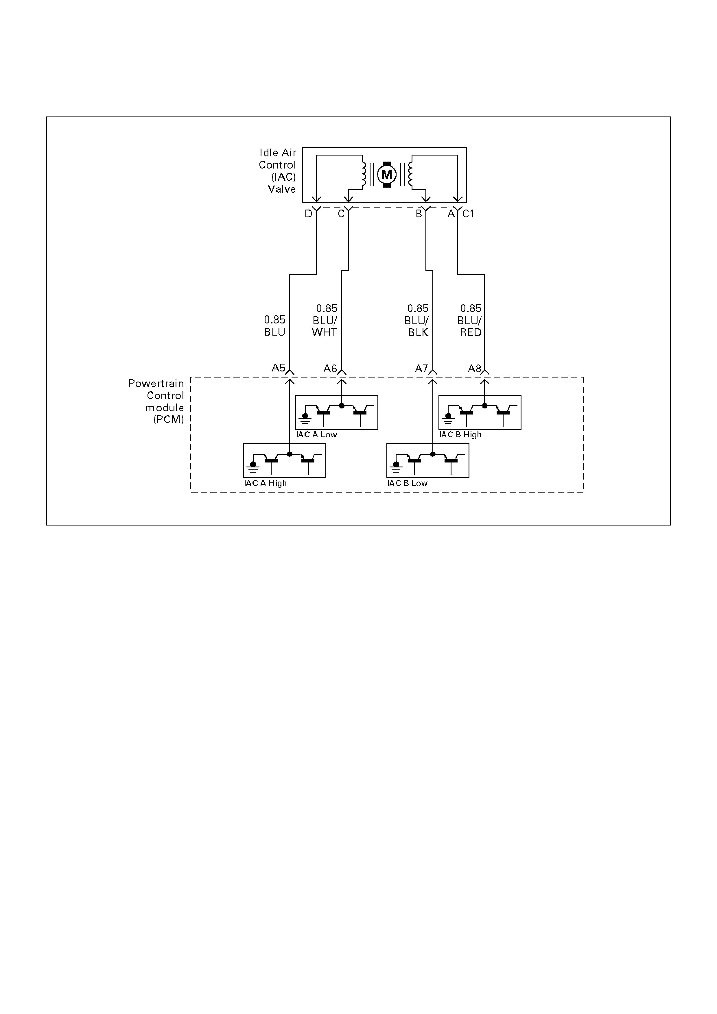
Diagnostic Trouble Code (DTC) P1508 IAC System Low RPM
T321115
Circuit Description
The powertrain control module (PCM) controls engine
idle speed by adjusting the position of the idle air control
(IAC) motor pintle. The IAC is a bi-directional stepper
motor driven by two coils. The PCM applies current to
the IAC coils in steps (counts) to extend the IAC pintle
into a passage in the throttle body to decrease air flow.
The PCM reverses the current to retract the pintle,
increasing air flow. This method allows highly accurate
control of idle speed and quick response to changes in
engine load. If the PCM detects a condition where too
low of an idle speed is present and the PCM is unable to
adjust idle speed by increasing the IAC counts, DTC
P1508 will set, indicating a problem with the idle control
system.
Conditions for Setting the DTC
• No Tech 2 test is being run.
• None of these DTCs are set: TP sensor, VSS, ECT,
EGR, fuel system, MAF, MAP, IAT, canister purge,
injector control or ignition control.
• Barometric pressure is above 75 kPa.
• Engine coolant temperature (ECT) is above 50°C
(120°F).
• Engine speed is more than 100-200 RPM lower than
desired idle, based upon coolant temperature.
• The engine has been running for at least 125
seconds.
• Vehicle speed is less than 1 mph.
• Canister purge duty cycle is above 10%.
• Ignition voltage is between 9.5 volts and 16.7 volts.
• The throttle is closed.
• Engine speed is lower than desired idle.
• All of the above conditions are met for 10 seconds.
Action Taken When the DTC Sets
• The PCM will illuminate the malfunction indicator
lamp (MIL) after the second consecutive trip in which
the fault is detected.
• The PCM will store conditions which were present
when the DTC was set as Freeze Frame and in the
Failure Records data.
Conditions for Clearing the MIL/DTC
• DTC P1508 can be cleared by using the Tech 2
“Clear Info” function or by disconnecting the PCM
battery feed.
Diagnostic Aids
Check for the following conditions:

•Poor connection at PCM or IAC motor – Inspect
harness connectors for backed-out terminals,
improper mating, broken locks, improperly formed or
damaged terminals, and poor terminal-to-wire
connection.
•Damaged harness – Inspect the wiring for damage.
•Restricted air intake system – Check for a possible
collapsed air intake duct, restricted air filter element,
or foreign objects blocking the air intake system.
•Throttle body – Check for objects blocking the IAC
passage or throttle bore, excessive deposits in the
IAC passage and on the IAC pintle, and excessive
deposits in the throttle bore and on the throttle plate.
•Large vacuum leak – Check for a condition that
causes a large vacuum leak, such as an incorrectly
installed or faulty PCV valve or a disconnected brake
booster hose.
Reviewing the Failure Records vehicle mileage since
the diagnostic test last failed may help determine how
often the condition that caused the DTC to be set
occurs. This may assist in diagnosing the condition.
DTC P1508 – IAC System Low RPM
StepActionValue(s)YesNo
1 Was the “On-Board Diagnostic (OBD) System Check”
performed? — Go to Step 2
Go to OBD
System Check
2 1. Start the engine.
2. Turn all accessories “OFF”(A/C, rear defroster,
etc).
3. Using a Tech 2, command RPM up to 1500, down
to 500, and the up to 1500 while monitoring the
“Engine Speed” on the Tech 2.
NOTE: This Tech 2 command may cause the engine
to “cut out” when RPM goes above 1500. If this
occurs, the “cutting out” will stop when the Tech 2
command for the test is discontinued, or if the Tech 2
command is changed to less than 1500 RPM.
Does the “Engine Speed” remain within the specified
value of the “Desired Idle” for each RPM command? ± 50 RPM
No trouble
found. Go to
Diagnostic Aids Go to Step 3
3 1. Disconnect the IAC.
2. Install IAC Node Light 5-8840-2312-0 or
equivalent.
3. With the engine running, command RPM up to
1500, down to 500, and then up to 1500 while
observing the node light.
NOTE: This Tech 2 command may cause the engine
to “cut out” when RPM goes above 1500. If this
occurs, the “cutting out” will stop when the Tech 2
command for the test is discontinued, or if the Tech 2
command is changed to less than 1500 RPM.
Does each node light cycle red and green
(never“OFF”)? — Go to Step 5 Go to Step 4
4 1. Check the following circuits for an open, short to
voltage, short ground, or poor connections at the
PCM:
• IAC “A” Low.
• IAC “A” High.
• IAC “B” Low.
• IAC “B” High.
2. If a problem is found, repair as necessary.
Was a problem found? — Verify repair Go to Step 8

5 Visually/physically inspect for following conditions:
•Restricted air intake system. Check for a possible
collapsed air intake duct, restricted air filter
element, or foreign objects blocking the air intake
system.
•Throttle body. Check for objects blocking the IAC
passage or throttle bore, excessive deposits in the
IAC passage and on the IAC pintle, and excessive
deposits in the throttle bore and on the throttle
plate.
Do any of the above require a repair?—
Refer to
appropriate
section for
on-vehicle
serviceGo to Step 6
6 1.Check for a poor connection at the IAC harness
connector.
2.If a problem is found, replace faulty terminals as
necessary.
Was a problem found?—Verify repairGo to Step 7
7 Replace the IAC valve.
Is the action complete?—Verify repair—
8 Replace the PCM.
Important: The replacement PCM must be
programmed. Refer to Sections OC1 Service
Programming System and 11A1 6VE1 Immobiliser.
Is the action complete? — Verify repair —
Step Action Value(s) Yes No

Diagnostic Trouble Code (DTC) P1509 IAC System High RPM
T321115
Circuit Description
The powertrain control module (PCM) controls engine
idle speed by adjusting the position of the idle air control
(IAC) motor pintle. The IAC is a bi-directional stepper
motor driven by two coils. The PCM applies current to
the IAC coils in steps (counts) to extend the IAC pintle
into a passage in the throttle body to decrease air flow.
The PCM reverses the current to retract the pintle,
increasing air flow. This method allows highly accurate
control of idle speed and quick response to changes in
engine load. If the PCM detect a condition where too
high of an idle speed is present and the PCM is unable
to adjust idle speed by increasing the IAC counts, DTC
P1509 will set, indicating a problem with the idle control
system.
Conditions for Setting the DTC
• No Tech 2 test is being run.
• None of these DTCs are set: TP sensor, VSS, ECT,
EGR, fuel system, MAF, MAP, IAT, canister purge,
injector control or ignition control.
• Barometric pressure is above 75 kPa.
• Engine coolant temperature is above 50°C (120°F).
• Engine speed is more than 100-200 RPM lower than
desired idle, based upon coolant temperature.
• The engine has been running for at least 125
seconds.
• Vehicle speed is less than 1 mph.
• Canister purge duty cycle is above 10%.
• Ignition voltage is between 9.5 volts and 16.7 volts.
• Engine speed is lower than desired idle.
• All of the above conditions are met for 5 seconds.
Action Taken When the DTC Sets
• The PCM will illuminate the malfunction indicator
lamp (MIL) after the second consecutive trip in which
the fault is detected.
• The PCM will store conditions which were present
when the DTC was set as Freeze Frame and in the
Failure Records data.
Conditions for Clearing the MIL/DTC
• DTC P1509 can be cleared by using the Tech 2
“Clear Info” function or by disconnecting the PCM
battery feed.
Diagnostic Aids
Check for the following conditions:
• Poor connection at PCM or IAC motor – Inspect
harness connectors for backed-out terminals,

improper mating, broken locks, improperly formed or
damaged terminals, and poor terminal-to-wire
connection.
•Damaged harness – Inspect the wiring for damage.
•Vacuum leak – Check for a condition that causes a
vacuum leak, such as disconnected or damaged
hoses, leaks at the EGR valve and the EGR pipe to
the intake manifold, leaks at the throttle body, faulty
or incorrectly installed PCV valve, leaks at the intake
manifold, etc.
•Throttle body – Check for sticking throttle plate. Also
inspect the IAC passage for deposits or objects which
keep the IAC pintle from fully extending.
Reviewing the Failure Records vehicle mileage since
the diagnostic test last failed may help determine how
often the condition that caused the DTC to be set
occurs. This may assist in diagnosing the condition.
DTC P1509 – IAC System High RPM
StepActionValue(s)YesNo
1 Was the “On-Board Diagnostic (OBD) System Check”
performed? — Go to Step 2
Go to OBD
System Check
2 1. Start the engine.
2. Turn all accessories “OFF” (A/C, rear defroster,
etc.).
3. Using a Tech 2, command RPM up to 1500, down
to 500, and then up to 1500 while monitoring
“Engine Speed” on the Tech 2.
NOTE: This Tech 2 command may cause the engine
to “cut out” when RPM goes above 1500. If this
occurs, the “cutting out” will stop when the Tech 2
command for the test is discontinued, or if the Tech 2
command is changed to less than 1500 RPM.
Does the “Engine Speed” remain within the specified
value of “Desired Idle” for each RPM command? ± 50 RPM
No trouble
found. Go to
Diagnostic Aids Go to Step 3
3 1. Disconnect the IAC.
2. Install IAC Node Light 5-8840-2312-0 or
equivalent.
3. With the engine running, command RPM up to
1500, down to 500, and then up to 1500 while
observing the node light.
NOTE: This Tech 2 command may cause the engine
to “cut out” when RPM goes above 1500. If this
occurs, the “cutting out” will stop when the Tech 2
command for the test is discontinued, or if the Tech 2
command is changed to less than 1500 RPM.
Does each node light cycle red and green
(never“OFF”)? — Go to Step 5 Go to Step 4
4 1. Check the following circuits for an open, short to
voltage, short ground, or poor connections at the
PCM:
• IAC “A” Low
• IAC “A” High
• IAC “B” Low
• IAC “B” High
2. If a problem is found, repair as necessary.
Was a problem found? — Verify repair Go to Step 8

5 Visually/physically inspect for following conditions:
•Vacuum leaks.
•Throttle plate or throttle shaft for binding.
•Accelerator and cruise control cables for being
misadjusted or for binding.
•Faulty, missing, or incorrectly installed PCV valve.
Do any of the above require a repair?—
Refer to
appropriate
section for
on-vehicle
serviceGo to Step 6
6 1.Check for a poor connection at the IAC harness
connector.
2.If a problem is found, replace faulty terminals as
necessary.
Was a problem found?—Verify repairGo to Step 7
7 Replace the IAC valve.
Is the action complete?—Verify repair—
8 Replace the PCM.
Important: The replacement PCM must be
programmed, Refer to Sections OC1 Service
Programming System and 11A1 6VE1 Immobiliser.
Is the action complete? — Verify repair —
Step Action Value(s) Yes No

Diagnostic Trouble Code (DTC) P1618 Serial Peripheral Interface (SPI) PCM Interprocessor
Communication Error
Circuit Description
The serial peripheral interface (SPI) communication is
used internally by the PCM to send messages between
the engine processor and the automatic transmission
processor. Included in each message sent between the
two-processors is a checksum of the message. Both
the engine processor and automatic transmission
processor will compare this check sum value with the
calculated value. If the checksums don't match, the
processor will view the new data as being corrupted and
ignore the values. The processor will then use the
previous message. The receiving processor will then
send a message to the sending processor informing it
that it's last message was corrupted.
Conditions for Setting the DTC
•Battery voltage is above 9.0 V for 2 seconds.
•The PCM detects an internal program fault (check
sum of data communications error).
•Check sum fault present for 3 out 6 seconds.
•No TCM resets for 2 seconds.
Action Taken When the DTC Sets
•The PCM will flash the “Check Trans” lamp the first
time the fault is detected.
•The PCM will store conditions which were present
when the DTC was set as Freeze Frame and in the
Failure Records data.
•The automatic transmission will operate in the “safety
mode” to protect the mechanical parts of the
transmission. Shift quality and/or gear changes may
not be normal.
Conditions for Clearing the MIL/DTC
•DTC P1618 can be cleared by using the Tech 2
“Clear Info” function or by disconnecting the PCM
battery feed.
DTC P1618 – Serial Peripheral Interface (SPI) PCM Interprocessor
Communication Error
StepActionValue(s)YesNo
1 Was the “On-Board Diagnostic (OBD) System Check”
performed?—Go to Step 2
Go to OBD
System Check
2 Is the EEPROM calibration the latest version
available?—Go to Step 4 Go to Step 3
3 Reprogram the PCM with the latest available
calibrations.
Does DTC 1618 re-appear when the OBD System
Check is repeated?—Go to Step 4
Repair
completed
4 Replace the PCM.
Important: The replacement PCM must be
programmed. Refer to Sections OC1 Service
Programming System and 11A1 6VE1 Immobiliser.
Is the action complete? — Verify repair —

Diagnostic Trouble Code (DTC) P1625 PCM Unexpected Reset
Circuit Description
The powertrain control module (PCM) monitors
unexpected PCM reset. This will not turn on MIL light
on, only records code DTC P1625.
Conditions for Setting the DTC
• Clock or COP reset.
Action Taken When the DTC Sets
• The PCM will not illuminate the malfunction indicator
lamp (MIL).
• The PCM will store conditions which were present
when the DTC was set as Failure Records only. This
information will not be stored as Freeze Frame data.
Conditions for Clearing the MIL/DTC
• DTC P1625 can be cleared by using the Tech 2
“Clear Info” function or by disconnecting the PCM
battery feed.
Diagnostic Aids
Check for the following conditions:
• P1625 alone stored does not need diagnosis. Clear
DTC code.
Diagnostic Trouble Code (DTC) P1626 - No Response From Immobiliser
4JX1 ICU Circuit.CDR
Circuit Description
The PCM decides whether that is an abnomality in the
Immobiliser control system. DTC P1626 or are recorded
by the PCM when there is no response from
Immobiliser.
Condition for Setting the DTC
•No signal from Immobiliser Control Unit to PCM
Action Taken When the DTC sets
•Rapid flashing of the MIL (“CHECK ENGINE” lamp).
•The Engine does not start.
Condition for Clearing the MIL/DTC
•Clear DTC information with TECH 2. Refer to Section
0C TECH 2 Diagnosis
Diagnostic Aids
Check for the following conditions:
• Poor connection at ECM and ImmobiliserInspect
harness connectors for backed out terminals,
improper mating, broken locks, improperly formed or
damaged terminals, and poor terminal to wire
connection.
• Damaged harness-Inspect the wiring harness for
damage, If the harness appears to be OK, disconnect
the PCM and Immobiliser, turn the ignition “ON" and
observe a voltmeter connected to the suspect driver
circuit at the ECM and Immobiliser harness connector
while moving connectors and wiring harnesses
relates to the MIL. A change in voltage will indicate
the location of the fault.
Immobiliser
Relay
Powertrain
Control
Module
Immobiliser
Control
Unit
Battery +ve
(Fuse C16)
Switched 12V
(Fuse C8)
Ground
Vehicle Speed
Signal
“Check Engine”
Lamp
DLC
DIAGNOSTIC
CONNECTION
DLC PIN 7
Antenna
Coil
0.5 YELLOW
0.5 RED/WHITE
0.5 LIGHT GREEN/WHITE
0.85 RED/YELLOW
0.5 PURPLE
0.5 WHITE/BLACK
0.5 GREEN/YELLOW
0.5 BLUE
0.5 BLACK
0.5 ORANGE/BLACK
3
9
7
1
5
4
8
10
6
2A-13
D7
7
3
Ignition
Switch

DTC P1626-No Response From Immobiliser
StepActionValue(s)YesNo
1Was the “On-Board Diagnostic (OBD) system Check"
performed? — Go to Step 2
Go to OBD
system check
2Using the Tech2 system selection menu, select ‘Body
- Immobiliser - DTC’ function.
Does the Tech2 display B**** appear?
—
Refer to
Section 11
“Engine
Immobiliser
System" Go to Step 3
3Using the Tech2 system selection menu, select
‘Powertrain - DTC’ function.
Does the Tech2 display a DTC P1626 as
“PRESENT”?
— Go to Step 4
Refer to
Diagnostic Aids
if DTC P1626 is
displayed as
“NOT
PRESENT”
4Check the PCM and ICU harness and connectors for:
1.Backed out terminals, improper mating, broken
locks, improperly formed or damaged terminals,
and poor terminal to wire connection.
2.Damaged harness - Inspect the wiring harness for
damage.
If a problem found, repair as necessary.
Was a problem found? — Verify repairGo to Step 5
5With a DMM, check for an open circuit or a short to
voltage circuit between PCM pin D7 and ICU pin 6
(white/black wire).
If a problem found, repair as necessary.
Was a problem found? — Verify repair Go to Step 6
6Replace the ECM.
Important: The replacement PCM must be
programmed. Refer to Section 0C-1 - Service
Programming System.
Important: Refer to Section 11 - Engine Immobiliser
System for the Immobiliser Programming procedure.
Important: Ensure the latest software program is
downloaded to the ECM.
Is the action complete?
— Verify repair —
Diagnostic Trouble Code (DTC) P1631 - Received Response Was Not Correct
060RA00003
Circuit Description
The PCM decides whether that is an abnomality in the
Immobiliser control system. A DTC P1631 is recorded
by the ECM when received response was not correct.
Condition for Setting the DTC
•Received response was not correct.
Action Taken When the DTC Sets
•Rapid flashing of the MIL (“CHECK ENGINE” lamp).
•The Engine does not start.
Condition for Clearing the MIL/DTC
•Clear DTC information with TECH 2. Refer to Section
0C TECH 2 Diagnosis
Diagnostic Aids
Check for the following conditions:
• Poor connection at PCM and Immobiliser - Inspect
harness connectors for backed out terminals,
improper mating, broken locks, improperly formed or
damaged terminals, and poor terminal to wire
connection.
• Damaged harness - Inspect the wiring harness for
damage, If the harness appears to be OK, disconnect
the PCM and Immobiliser, turn the ignition “ON" and
observe a voltmeter connected to the suspect driver
circuit at the PCM and Immobiliser harness connector
while moving connectors and wiring harnesses
relates to the MIL. A change in voltage will indicate
the location of the fault.
Immobiliser
Relay
Powertrain
Control
Module
Immobiliser
Control
Unit
Battery +ve
(Fuse C16)
Switched 12V
(Fuse C8)
Ground
Vehicle Speed
Signal
“Check Engine”
Lamp
DLC
DIAGNOSTIC
CONNECTION
DLC PIN 7
Antenna
Coil
0.5 YELLOW
0.5 RED/WHITE
0.5 LIGHT GREEN/WHITE
0.85 RED/YELLOW
0.5 PURPLE
0.5 WHITE/BLACK
0.5 GREEN/YELLOW
0.5 BLUE
0.5 BLACK
0.5 ORANGE/BLACK
3
9
7
1
5
4
8
10
6
2 A-13
D7
7
3
Ignition
Switch

DTC P1631 - Received Response Was Not Correct
StepActionValue(s)YesNo
1Was the “On-Board Diagnostic (OBD) system Check"
performed? — Go to Step 2
Go to OBD
system check
2Using the Tech2 system selection menu, select ‘Body
- Immobiliser - DTC’ function.
Does the Tech2 display B**** appear?
—
Refer to
Section 11
“Engine
Immobiliser
System" Go to Step 3
3Using the Tech2 system selection menu, select
‘Powertrain - DTC’ function.
Does the Tech2 display a DTC P1631 as
“PRESENT”?
— Go to Step 4
Refer to
Diagnostic Aids
if DTC P1631 is
displayed as
“NOT
PRESENT”
4Check the ECM and ICU harness and connectors for:
1.Backed out terminals, improper mating, broken
locks, improperly formed or damaged terminals,
and poor terminal to wire connection.
2.Damaged harness - Inspect the wiring harness for
damage.
If a problem found, repair as necessary.
Was a problem found?
Verify repairGo to Step 5
5Replace the PCM.
Important: The replacement PCM must be
programmed. Refer to Section 0C-1 - Service
Programming System.
Important: Refer to Section 11 - Engine Immobiliser
System for the Immobiliser Programming procedure.
Important: Ensure the latest software program is
downloaded to the PCM.
Is the action complete?
— Verify repair —

Diagnostic Trouble Code (DTC) P1640 Driver-1-Input High Voltage
Circuit Description
Output driver modules (ODMs) are used by the
powertrain control module (PCM) to turn “ON” many of
the current-driven devices that are needed to control
various engine and transmission functions. Each ODM
is capable of controlling up to 7 separate outputs by
applying ground to the device which the PCM is
commanding “ON.”
Unlike the Quad Driver Modules (QDMs) used in prior
model years, ODMs have the capability of diagnosing
each output circuit individually. DTC P1640 set
indicates an improper voltage level has been detected
on an ODM output.
Since A/C is an option, No A/C will cause the air
conditioning clutch relay output to always fault. If a fault
is seen on the air conditioning clutch relay output, it will
not be logged as a fault until the A/C request input
interrupts a high voltage, indicating that A/C has been
installed.
Conditions for Setting the DTC
• Ignition “ON.”
• Engine running.
• No DTC 1618.
• Ignition voltage is above 13.2 volts for 4 seconds.
• Output voltage does not equal ignition voltage when
output is “OFF” or output voltage is not less than 1
volt when output is “ON.”
• Above conditions occur for at least 1 second.
Action Taken When the DTC Sets
• The PCM will not illuminate the malfunction indicator
lamp (MIL).
• The PCM will store conditions which were present
when the DTC was set as Failure Records only. This
information will not be stored as Freeze Frame data.
Conditions for Clearing the MIL/DTC
• DTC P1640 can be cleared by using the Tech 2
“Clear Info” function or by disconnecting the PCM
battery feed.
Diagnostic Aids
Check for the following conditions:
• Poor connection at PCM – Inspect harness
connectors for backed-out terminals, improper
mating, broken locks, improperly formed or damaged
terminals, and poor terminal-to-wire connection.
• Damaged harness – Inspect the wiring harness for
damage, If the harness appears to be OK,
disconnect the PCM, turn the ignition “ON” and
observe a voltmeter connected to the suspect driver
circuit at the PCM harness connector while moving
connectors and wiring harnesses relates to the MIL.
A change in voltage will indicate the location of the
fault.
• Poor connection at component – Examine for
damaged connectors, unplugged connector, or
damaged terminals at the following locations:
Instrument cluster harness, canister purge solenoid,
A/C clutch relay. An open ignition feed circuit at any
of these components will cause DTC P1640 to be set.
Reviewing the Failure Records vehicle mileage since
the diagnostic test last failed may help determine how
often the condition that caused the DTC to be set
occurs. This may assist in diagnosing the condition.
The following PCM pins are controlled by output driver
modules (ODMs):
• A13 – “Check Engine Lamp”
• A14 – "Check Trans"
• B14 – A/C Clutch
Test Description
Number(s) below refer to the step number(s) on the
Diagnostic Chart.
6. The Tech 2 Driver Module Status indicates the PCM
pin that is affected.
11. The Tech 2 may indicate “short circuit” even when
the problem is an open circuit. The cause of an
open circuit may be in the component itself-lamp,
purge, solenoid, or A/C compressor relay.
13. A short to ground on the ignition side of the
component will blow the fuse. Since the fuse was
checked in Step 4, a short to ground would be
between the affected component and the PCM.

DTC P1640 – Driver-1-Input High Voltage
StepActionValue(s)YesNo
1 Was the “On-Board Diagnostic (OBD) System Check”
performed? — Go to Step 2
Go to OBD
System Check
2 1. Ignition “ON,”engine “OFF.”
2. Install the Tech 2.
3. Review and record Tech 2 Failure Records data.
4. Operate the vehicle within Failure Records
conditions as noted.
5. Use the Tech 2 to indicate DTC P1640.
Does the Tech 2 indicate DTC P1640? — Go to Step 3 —
3 Check the fuse for the driver circuit that was shown as
faulty.
Was the fuse blown? — Go to Step 4 Go to Step 5
4 1. Check for a short to ground between the fuse and
the affected component.
2. Replace the fuse after making any necessary
repairs.
Is the action complete? — Verify repair —
5 Disconnect the PCM connector for the affected driver
circuit.
Is there any damage to the PCM pin or connector? — Go to Step 6 Go to Step 7
6 Repair the damaged pin or terminal.
Is the action complete? — Verify repair —
7 Were either of the lamp circuits for “Check Engine” or
“Check Trans.” indicated as faulty by the Tech 2? — Go to Step 8 Go to Step 14
8 1. Leave the PCM connector for the lamp driver
circuit disconnected.
2. Ignition “ON.”
3. Using a DVM, check the voltage at the PCM
connector for the affected lamp driver circuit.
Was the voltage equal to the specified value? B+ Go to Step 16 Go to Step 9
9 1. Ignition “ON.”
2. Check for battery voltage at the fuse for the
affected lamp circuit.
Was battery voltage available at the fuse? — Go to Step 11 Go to Step 10
10 Repair the open circuit between the ignition switch
and the fuse.
Is the action complete? — Verify repair —
11 1. Ignition “OFF.”
2. Disconnect the PCM connector for the affected
driver terminal.
3. Connect an ohmmeter between a good ground
and the PCM connector for the affected driver.
Did the ohmmeter indicate continuity? — Go to Step 12 Go to Step 13
12 Repair the short to ground between the affected
component and its PCM driver terminal.
Is the action complete? — Verify repair —
13 Repair the open circuit between the fuse and the PCM
driver terminal for the affected circuit.
Is the action complete? — Verify repair —

14 1.Connect the PCM.
2.Start the engine and let it idle.
3.Backprobe the affected terminal at the PCM with a
DVM.
Was the voltage equal to the specified value?+BGo to Step 16Go to Step 15
15 1.Run the engine at idle.
2.Check for battery voltage at the fuse for the
affected circuit.
Was battery voltage available at the fuse?—Go to Step 11Go to Step 10
16 Replace the PCM.
Important: The replacement PCM must be
programmed. Refer to Sections OC1 Service
Programming System and 11A1 6VE1 Immobiliser.
Is the action complete? — Verify repair —
Step Action Value(s) Yes No
Diagnostic Trouble Code (DTC) P1648 - Received Incorrect Security Code
060RA00003
Circuit Description
The PCM decides whether that is an abnomality in the
Immobiliser control system. A DTC P1648 is recorded
by the PCM when it receives an incorrect security code.
Condition for Setting the DTC
•Received security code is incorrect.
Action Taken When the DTC Sets
•Rapid flashing of the MIL (“CHECK ENGINE” lamp).
•The Engine does not start.
Condition for Clearing the MIL/DTC
•Clear DTC information with TECH 2. Refer to Section
0C TECH 2 Diagnosis
Diagnostic Aids
Check for the following conditions:
• Poor connection at PCM and Immobiliser - Inspect
harness connectors for backed out terminals,
improper mating, broken locks, improperly formed or
damaged terminals, and poor terminal to wire
connection.
• Damaged harness - Inspect the wiring harness for
damage, If the harness appears to be OK, disconnect
the PCM and Immobiliser, turn the ignition “ON" and
observe a voltmeter connected to the suspect driver
circuit at the PCM and Immobiliser harness connector
while moving connectors and wiring harnesses
relates to the MIL. A change in voltage will indicate
the location of the fault.
Immobiliser
Relay
Powertrain
Control
Module
Immobiliser
Control
Unit
Battery +ve
(Fuse C16)
Switched 12V
(Fuse C8)
Ground
Vehicle Speed
Signal
“Check Engine”
Lamp
DLC
DIAGNOSTIC
CONNECTION
DLC PIN 7
Antenna
Coil
0.5 YELLOW
0.5 RED/WHITE
0.5 LIGHT GREEN/WHITE
0.85 RED/YELLOW
0.5 PURPLE
0.5 WHITE/BLACK
0.5 GREEN/YELLOW
0.5 BLUE
0.5 BLACK
0.5 ORANGE/BLACK
3
9
7
1
5
4
8
10
6
2 A-13
D7
7
3
Ignition
Switch

DTC P1648 - Received Incorrect Security Code
StepActionValue(s)YesNo
1Was the “On-Board Diagnostic (OBD) system Check"
performed? — Go to Step 2
Go to OBD
system check
2 Using the Tech2 system selection menu, select ‘Body
- Immobiliser - DTC’ function.
Does the Tech2 display B**** appear?
—
Refer to
Section 11
“Engine
Immobiliser
System" Go to Step 3
3 Using the Tech2 system selection menu, select
‘Powertrain - DTC’ function.
Does the Tech2 display a DTC P1648 as
“PRESENT”?
— Go to Step 4
Refer to
Diagnostic Aids
if DTC P1648 is
displayed as
“NOT
PRESENT”
4 Check the PCM and ICU harness and connectors for:
1. Backed out terminals, improper mating, broken
locks, improperly formed or damaged terminals,
and poor terminal to wire connection.
2. Damaged harness - Inspect the wiring harness for
damage.
If a problem found, repair as necessary.
Was a problem found? Verify repair Go to Step 5
5 Recheck the security code.
Is the action complete? — Verify repair —
Diagnostic Trouble code (DTC) P1649 - Security Code & Security Key Not Programmed
060RA00003
Circuit Description
The PCM decides whether that is an abnomality in the
Immobiliser control system. DTC P1649 are recorded
by the PCM when security code & secret key not
programmed.
Condition for Setting the DTC
•Security code & secret key not programmed.
Action Taken When the DTC Sets
•Rapid flashing of the MIL (“CHECK ENGINE” lamp).
•The Engine does not start.
In case replacement ECM/ECM, Action
Taken When the DTC Sets
•Rapid flashing of the MIL (“CHECK ENGINE” lamp).
•The Engine does not start.
Condition for Clearing the MIL/DTC
•Clear DTC information with TECH 2. Refer to Section
0C TECH 2 Diagnosis
Diagnostic Aids
Check for the following conditions:
• Poor connection at PCM and ImmobiliserInspect
harness connectors for backed out terminals,
improper mating, broken locks, improperly formed or
damaged terminals, and poor terminal to wire
connection.
• Damaged harness-Inspect the wiring harness for
damage, If the harness appears to be OK, disconnect
the PCM and Immobiliser, turn the ignition “ON" and
observe a voltmeter connected to the suspect driver
circuit at the PCM and Immobiliser harness connector
while moving connectors and wiring harnesses
relates to the MIL.
A change in voltage will indicate the location of the
fault.
Immobiliser
Relay
Powertrain
Control
Module
Immobiliser
Control
Unit
Battery +ve
(Fuse C16)
Switched 12V
(Fuse C8)
Ground
Vehicle Speed
Signal
“Check Engine”
Lamp
DLC
DIAGNOSTIC
CONNECTION
DLC PIN 7
Antenna
Coil
0.5 YELLOW
0.5 RED/WHITE
0.5 LIGHT GREEN/WHITE
0.85 RED/YELLOW
0.5 PURPLE
0.5 WHITE/BLACK
0.5 GREEN/YELLOW
0.5 BLUE
0.5 BLACK
0.5 ORANGE/BLACK
3
9
7
1
5
4
8
10
6
2 A-13
D7
7
3
Ignition
Switch

DTC P1649 - Security Code & Secret Key Not Programmed
StepActionValue(s)YesNo
1Was the “On-Board Diagnostic (OBD) system Check"
performed? — Go to Step 2
Go to OBD
system check
2Using the Tech2 system selection menu, select Body
function.
Does the Tech2 display a DTC B****?
—
Refer to
Section11
“Engine
Immobiliser
System" Go to Step 3
3Using the Tech2 system selection menu, select
‘Powertrain - DTC’ function.
Does the Tech2 display a DTC P1649 as
“PRESENT”?
— Go to Step 4
Refer to
Diagnostic Aids
if DTC P1649 is
displayed as
“NOT
PRESENT”
4Replace the PCM.
Important: The replacement ECM must be
programmed. Refer to Section 0C-1 - Service
Programming System.
Important: Refer to Section 11 - Engine Immobiliser
System for the Immobiliser Programming procedure.
Important: Ensure the latest software program is
downloaded to the ECM.
Is the action complete?
— Go to Step 5 —
5 Does the Tech2 display a DTC P1649? — Go to Step 3 Verify repair

Symptom Diagnosis
Preliminary Checks
Before using this section, perform the “On-Board
Diagnostic (OBD) System Check” and verify all of the
following items:
•The Powertrain Control Module (PCM) and
malfunction indicator lamp (MIL) (Service Engine
Soon lamp) are operating correctly.
•There are no DTC(s) stored.
•Tech 2 data is within normal operating range. Refer
to Typical Scan Data Values.
•Verify the customer complaint and locate the correct
symptom in the table of contents. Perform the
procedure included in the symptom chart.
Visual/Physical Check
Several of the symptom procedures call for a careful
visual/physical check. This can lead to correcting a
problem without further checks and can save valuable
time.
This check should include the following items:
•PCM grounds for cleanliness, tightness and proper
location.
•Vacuum hoses for splits, kinks, and proper
connections, as shown on the “Vehicle Emission
Control Information” label. Check thoroughly for any
type of leak or restriction.
•Air intake ducts for collapsed or damaged areas.
•Air leaks at throttle body mounting area, mass air flow
(MAF) sensor and intake manifold sealing surfaces.
•Ignition wires for cracking, hardness, and carbon
tracking.
•Wiring for proper connections, pinches and cuts.
Intermittents
Important: An intermittent problem may or may not
turn on the malfunction indicator lamp (MIL) or store a
DTC. DO NOT use the Diagnostic Trouble Code (DTC)
charts for intermittent problems. The fault must be
present to locate the problem.
Most intermittent problems are caused by faulty
electrical connections or wiring. Perform a careful
visual/physical check for the following conditions:
•Poor mating of the connector halves or a terminal not
fully seated in the connector (backed out).
•Improperly formed or damaged terminal.
•All connector terminals in the problem circuit should
be carefully checked for proper contact tension.
•Poor terminal-to-wire connection. This requires
removing the terminal from the connector body to
check.
Road test the vehicle with a J 39200 Digital Multimeter
connected to a suspected circuit. An abnormal voltage
when the malfunction occurs is a good indication that
there is a fault in the circuit being monitored.
Use Tech 2 to help detect intermittent conditions. Tech
2s have several features that can be used to locate an
intermittent condition. Use the following feature to find
intermittent faults:
•Using Tech 2's “Freeze Frame” buffer or “Failure
Records” buffer can aid in locating an intermittent
condition. Review and record the information in the
freeze frame or failure record associated with the
intermittent DTC being diagnosed. The vehicle can
be driven within the conditions that were present
when the DTC originally set.
To check for loss of diagnostic code memory,
disconnect the MAP sensor and idle the engine until the
MIL (Service Engine Soon lamp) comes on. DTC
P0107 should be stored and kept in memory when the
ignition is turned “OFF.” If not, the PCM is faulty. When
this test is completed, make sure that you clear the DTC
P0107 from memory.
Intermittent MIL illumination with no stored DTC may be
caused by the following:
•Ignition coil shorted to ground and arcing at ignition
wires or plugs.
•MIL wire to PCM shorted to ground.
•Poor PCM grounds. Refer to the PCM wiring
diagrams.
Check for improper installation of electrical options such
as lights, cellular phones, etc. Route ignition coil wiring
away from the ignition coils. Check all wires from the
PCM to the ignition coil for poor connections.
Check for an open diode across the A/C compressor
clutch and check for other open diodes (refer to wiring
diagrams in Electrical Diagnosis).
If problem has not been found, refer to PCM Connector
Symptom tables.

Hard Start Symptom
StepActionValue(s)YesNo
1 DEFINITION: Engine cranks, but does not start for a
long time. Does eventually run, or may start but
immediately stalls.
Was the “On-Board Diagnostic (OBD) System Check”
performed? — Go to Step 2
Go to OBD
System Check
2 1. Perform a bulletin search.
2. If a bulletin that addresses the symptom is found,
correct the condition as instructed in the bulletin.
Was a bulletin found that addresses the symptom? — Verify repair Go to Step 3
3 Was a visual/physical check performed?
—Go to Step 4
Go to Visual/
Physical Check
4 Check engine coolant temperature (ECT) sensor for
shift in value. After 8 hours with the hood up and the
engine not running, connect Tech 2. With the ignition
“ON” and the engine not running, compare engine
coolant temperature to intake air temperature.
Are ECT and IAT within the specified value of each
other? ± 5°C (± 9°F) Go to Step 8 Go to Step 5
5 1. Using Tech 2, display the engine coolant
temperature and note the value.
2. Check the resistance of the engine coolant
temperature sensor.
3. Refer to Engine Coolant Temperature Sensor
Temperature vs. Resistance chart on DTC P0118
Diagnostic Support for resistance specifications.
Is the resistance value near the resistance for the
temperature noted? — Go to Step 7 Go to Step 6
6 Replace the ECT sensor.
Is the action complete? — Verify repair —
7 Locate and repair high resistance or poor connection
in the ECT signal circuit or the ECT sensor ground.
Is the action complete? — Verify repair —
8 1. Check for a faulty, plugged, or incorrectly installed
PCV valve.
2. If a problem is found, repair as necessary.
Was a problem found? — Verify repair Go to Step 9
9 1. Check for water- or alcohol-contaminated fuel.
2. If a problem is found, repair as necessary.
Was a problem found? — Verify repair Go to Step 10
10 1. Perform the procedure in Fuel System Pressure
Test.
2. If a problem is found, repair as necessary.
Was a problem found? — Verify repair Go to Step 11
11 1. Check for proper ignition voltage output with spark
tester 5-8840-0383-0. Refer to Electric Ignition
System for procedure.
2. If a problem is found, repair as necessary.
Was a problem found? — Verify repair Go to Step 12

12 1. Remove spark plugs. Check for wet plugs,
cracks, wear, improper gap, burned electrodes, or
heavy deposits.
1. If spark plugs are fuel or oil fouled, the cause of
the fouling must be determined before replacing
the spark plugs.
2. If a problem is found, repair as necessary.
Was a problem found? — Verify repair Go to Step 13
13 1. Check for a loose ignition coil ground.
2. If a problem is found, repair as necessary.
Was a problem found? — Verify repair Go to Step 14
14 1. Remove the ignition coils and check the ignition
coils for cracks or carbon tracking.
2. If a problem is found, replace affected coil(s) as
necessary.
Was a problem found? — Verify repair Go to Step 15
15 1. Check IAC operation. Perform the procedure in
the DTC P0506, Step 6 diagnostic table.
2. If a problem is found, repair as necessary.
Was a problem found? — Verify repair Go to Step 16
16 1. Check for the following engine mechanical
problems (refer to Engine Mechanical):
• Low compression
• Leaking cylinder head gaskets
• Worn or incorrect camshaft
• Camshaft drive belt slipped or stripped
2. If a problem is found, repair as necessary.
Was a problem found? — Verify repair Go to Step 17
17 1. Review all diagnostic procedures within this table.
2. If all procedures have been completed and no
malfunctions have been found, review/inspect the
following:
• Visual/physical inspection
• Tech 2 data
• Freeze Frame data/Failure Records buffer
• All electrical connections within a suspected
circuit and/or system.
3. If a problem is found, repair as necessary.
Was a problem found? — Verify repair
Contact
Te ch n ic al
Assistance
Step Action Value(s) Yes No

Surges and/or Chuggles Symptom
StepActionValue(s)YesNo
1 DEFINITION:
Engine power variation under steady throttle or cruise.
Feels like the vehicle speeds up and slows down with
no change in the accelerator pedal.
Was the “On-Board Diagnostic (OBD) System Check”
performed? — Go to Step 2
Go to OBD
System Check
2 1. Perform a bulletin search.
2. If a bulletin that addresses the symptom is found,
correct the condition as instructed in the bulletin.
Was a bulletin found that addresses the symptom? — Verify repair Go to Step 3
3 Was a visual/physical check performed?
—Go to Step 4
Go to Visual/
Physical Check
4 Be sure that the driver understands transmission
torque converter clutch and A/C compressor operation
as explained in the owner's manual.
Inform the customer how the TCC and the A/C clutch
operate.
Is the customer experiencing a normal condition? — System OK Go to Step 5
5 1. Check the the fuel control heated oxygen sensors
(HO2S, B1S1 and B2S1). The fuel control heated
oxygen sensors (HO2S) should respond quickly to
different throttle positions. If they don't, check
them for silicon or other contaminants from fuel or
use of improper RTV sealant. The sensors may
have a white powdery coating.
Silicon contamination causes a high but false
HO2S signal voltage (rich exhaust indication).
The PCM will then reduce the amount of fuel
delivered to the engine, causing a severe
driveability problem. For more information, refer
to Powertrain Control Module (PCM) and Sensors.
2. If a problem is found, repair as necessary.
Was a problem found? — Verify repair Go to Step 6
6 1. Check the fuel pressure. Refer to Fuel System
Pressure Test.
2. If a problem is found, repair as necessary.
Was a problem found? — Verify repair Go to Step 7
7 Monitor the long term fuel trim on Tech 2.
Is the long term fuel trim significantly in the negative
range (rich condition)? — Go to Step 8 Go to Step 9
8 1. Check items that can cause the engine to run rich.
Refer to Diagnostic Aids in DTC P0172 Diagnostic
Support.
2. If a problem is found, repair as necessary.
Was a problem found? — Go to Step 10 Verify repair
9 1. Check items that can cause the engine to run
lean. Refer to Diagnostic Aids in DTC P0171.
2. If a problem is found, repair as necessary.
Was a problem found? — Go to Step 10 Verify repair

10 1. Check for proper ignition voltage output with spark
tester J 26792 (ST-125).
2. If a problem is found, repair as necessary.
Was a problem found? — Verify repair Go to Step 11
11 1. Check for a loose ignition coil ground.
2. If a problem is found, repair as necessary.
Was a problem found? — Verify repair Go to Step 12
12 1. Check the ignition coils for cracks or carbon
tracking.
2. If a problem is found, repair as necessary.
Was a problem found? — Verify repair Go to Step 13
13 1. Remove the spark plugs and check for wet plugs,
cracks, wear, improper gap, burned electrodes, or
heavy deposits.
1. If spark plugs are fuel or oil fouled, the cause of
the fouling must be determined before replacing
the spark plugs.
2. If a problem is found, repair as necessary.
Was a problem found? — Verify repair Go to Step 14
14 1. Check the injector connections.
2. If any of the injector connectors are connected to
an incorrect cylinder, correct as necessary.
Was a problem found? — Verify repair Go to Step 15
15 1. Check PCM grounds for the cleanliness, tightness
and proper locations.
2. If a problem is found, repair as necessary.
Was a problem found? — Verify repair Go to Step 16
16 1. Check MAF sensor connections.
2. If a problem is found, replace the faulty terminals
as necessary. Refer to Electrical Diagnosis for
wiring repair procedures.
Was a problem found? — Verify repair Go to Step 17
17 1. Visually/physically check vacuum hoses for splits,
kinks, and proper connections and routing as
shown on the “Vehicle Emission Control
Information” label.
2. If a problem is found, repair as necessary.
Was a problem found? — Verify repair Go to Step 18
18 1. Check the exhaust system for possible restriction:
• Inspect the exhaust system for damaged or
collapsed pipes.
• Inspect the muffler for heat distress or possible
internal failure.
• Check for a possible plugged three-way
catalytic converter by checking the exhaust
system back pressure. Refer to Restricted
Exhaust System Check.
2. If a problem is found, repair as necessary.
Was a problem found? — Verify repair Go to Step 19
Step Action Value(s) Yes No

19 1. Review all diagnostic procedures within this table.
2. If all procedures have been completed and no
malfunctions have been found, review/inspect the
following:
• Visual/physical inspection
• Tech 2 data
• Freeze Frame data/Failure Records buffer
• All electrical connections within a suspected
circuit and/or system.
3. If a problem is found, repair as necessary.
Was a problem found? — Verify repair
Contact
Te ch n ic al
Assistance
Step Action Value(s) Yes No

Lack of Power, Sluggish or Spongy Symptom
StepActionValue(s)YesNo
1 DEFINITION:
Engine delivers less than expected power. Little or no
increase in speed when accelerator pedal is pushed
down part-way.
Was the “On-Board Diagnostic (OBD) System Check”
performed? — Go to Step 2
Go to OBD
System Check
2 1. Perform a bulletin search.
2. If a bulletin that addresses the symptom is found,
correct the condition as instructed in the bulletin.
Was a bulletin found that addresses the symptom? — Verify repair Go to Step 3
3 Was a visual/physical check performed?
—Go to Step 4
Go to Visual/
Physical Check
4 1. Remove and check the air filter element for dirt or
restrictions. Refer to Air Intake System in
ON-Vehicle Service.
2. Replace the air filter element if necessary.
Was a repair required? — Verify repair Go to Step 5
5 1. Check for low fuel pressure. Refer to Fuel System
Pressure Test.
2. If a problem is found, repair as necessary.
Was a problem found? — Verify repair Go to Step 6
6 1. Check for water- or alcohol-contaminated fuel.
2. If a problem is found, repair as necessary.
Was a problem found? — Verify repair Go to Step 7
7 1. Using Tech 2, monitor the knock sensor (KS)
system for excessive spark retard activity. Refer
to Knock Sensor (KS) System.
2. If a problem is found, repair as necessary.
Was a problem found? — Verify repair Go to Step 8
8 1. Check for proper ignition voltage output with spark
tester J 26792 (ST-125).
2. If a problem is found, repair as necessary.
Was a problem found? — Verify repair Go to Step 9
9 1. Remove the spark plugs and check for wet plugs,
cracks, wear, improper gap, burned electrodes, or
heavy deposits.
2. If spark plugs are gas or oil fouled, the cause of
the fouling must be determined before replacing
the spark plugs.
3. If a problem is found, repair as necessary.
Was a problem found? — Verify repair Go to Step 10
10 1. Check the ignition coils for cracks or carbon
tracking.
2. If a problem is found, repair as necessary.
Was a problem found? — Verify repair Go to Step 11
11 1. Check the PCM grounds for the cleanliness,
tightness and proper locations. Refer to the PCM
wiring diagrams in Electrical Diagnosis.
2. If a problem is found, repair as necessary.
Was a problem found? — Verify repair Go to Step 12

12 1. Check the exhaust system for possible restriction:
• Inspect the exhaust system for damaged or
collapsed pipes.
• Inspect the muffler for heat distress or possible
internal failure.
• Check for a possible plugged three-way
catalytic converter by checking the exhaust
system back pressure. Refer to Restricted
Exhaust System Check.
2. If a problem is found, repair as necessary.
Was a problem found? — Verify repair Go to Step 13
13 1. Check the torque converter clutch (TCC) for
proper operation. Refer to 4L30-E Transmission
Diagnosis.
2. If a problem is found, repair as necessary.
Was a problem found? — Verify repair Go to Step 14
14 1. Check for an engine mechanical problem. Check
for low compression, incorrect or worn camshaft,
loose timing belt, etc. Refer to Engine
Mechanical.
2. If a problem is found, repair as necessary.
Was a problem found? — Verify repair Go to Step 15
15 1. Review all diagnostic procedures within this table.
2. If all procedures have been completed and no
malfunctions have been found, review/inspect the
following:
• Visual/physical inspection
• Tech 2 data
• Freeze Frame data/Failure Records buffer
• All electrical connections within a suspected
circuit and/or system.
3. If a problem is found, repair as necessary.
Was a problem found? — Verify repair
Contact
Te ch n ic al
Assistance
Step Action Value(s) Yes No

Detonation/Spark Knock Symptom
StepActionValue(s)YesNo
1 DEFINITION:
A mild to severe ping, usually worse under
acceleration. The engine makes sharp metallic
knocks that change with throttle opening.
Was the “On-Board Diagnostic (OBD) System Check”
performed? — Go to Step 2
Go to OBD
System Check
2 1. Perform a bulletin search.
2. If a bulletin that addresses the symptom is found,
correct the condition as instructed in the bulletin.
Was a bulletin found that addresses the symptom? — Verify repair Go to Step 3
3 Was a visual/physical check performed?
—Go to Step 4
Go to Visual/
Physical Check
4 If Tech 2 readings are normal (refer to Typical Scan
Values) and there are no engine mechanical faults, fill
the fuel tank with a known quality gasoline that has a
minimum octane rating of 87 and re-evaluate the
vehicle performance.
Is detonation present? — Go to Step 5 Verify repair
5 1. Check the transmission range switch circuit. Use
Tech 2 and be sure Tech 2 indicates that the
vehicle is in drive with the gear selector in drive or
overdrive.
2. If a problem is found, diagnose and repair the
transmission range switch as necessary (refer to
4L30-E Automatic Transmission Diagnosis).
Was a problem found? — Verify repair Go to Step 6
6 1. Check TCC operation. Refer to 4L30-E
Transmission Diagnosis.
2. If a problem is found, repair as necessary.
Was a problem found? — Verify repair Go to Step 7
7 1. Check for obvious overheating problems:
• Low engine coolant.
• Restricted air flow to radiator, or restricted water
flow through radiator.
• Correct coolant solution should be a 50/50 mix
of approved HN2217 Coolant and water. Refer
to Engine Cooling.
2. If a problem is found, repair as necessary.
Was a problem found? — Verify repair Go to Step 8
8 1. Check fuel pressure. Refer to Chart Fuel System
Pressure Test.
2. If a problem is found, repair as necessary.
Was a problem found? — Verify repair Go to Step 9
9 1. Check items that can cause an engine to run lean
(long term fuel trim significantly in the positive
range). For a lean condition, refer to Diagnostic
Aids in DTC P0171 Diagnostic Support.
2. If a problem is found, repair as necessary.
Was a problem found? — Verify repair Go to Step 10

Rough, Unstable, or Incorrect Idle, Stalling Symptom
10 1.Spark plugs for proper heat range. Refer to
General Information.
2.If incorrect spark plugs are installed, replace spark
plugs as necessary.
Did any spark plugs require replacement?—Verify repairGo to Step 11
11 1.Remove excessive carbon buildup with a top
engine cleaner. Refer to instructions on the top
engine cleaner can.
2.Re-evaluate vehicle performance.
Is detonation still present?—Go to Step 12 Verify repair
12 1.Check for an engine mechanical problem.
Perform a cylinder compression check. Refer to
Engine Mechanical.
2.If a problem is found, repair as necessary.
Was a problem found?—Verify repairGo to Step 13
13 1.Review all diagnostic procedures within this table.
2.If all procedures have been completed and no
malfunctions have been found, review/inspect the
following:
•Visual/physical inspection
•Tech 2 data
•Freeze Frame data/Failure Records buffer
•All electrical connections within a suspected
circuit and/or system.
3.If a problem is found, repair as necessary.
Was a problem found?—Verify repair
Contact
Technical
Assistance
StepActionValue(s)YesNo
1 DEFINITION:
Engine runs unevenly at idle. If severe, the engine or
vehicle may shake. Engine idle speed may vary in
RPM. Either condition may be severe enough to stall
the engine.
Was the “On-Board Diagnostic (OBD) System Check”
performed? — Go to Step 2
Go to OBD
System Check
2 1. Perform a bulletin search.
2. If a bulletin that addresses the symptom is found,
correct the condition as instructed in the bulletin.
Was a bulletin found that addresses the symptom? — Go to Step 13 Go to Step 3
3 Was a visual/physical check performed?
—Go to Step 4
Go to Visual/
Physical Check
4 1. Check the PCM grounds for cleanliness, tightness
and proper routing. Refer to the PCM wiring
diagrams in Electrical Diagnosis.
2. If a problem is found, repair as necessary.
Was a problem found? — Verify repair Go to Step 5
5 Observe the long term fuel trim on Tech 2.
Is the long term fuel trim significantly in the negative
range (rich condition)? — Go to Step 6 Go to Step 7
Step Action Value(s) Yes No

6 1. Check items that can cause the engine to run rich.
Refer to Diagnostic Aids in DTC P0172 Diagnostic
Support.
2. If a problem is found, repair as necessary.
Was a problem found? — Verify repair Go to Step 9
7 Is the long term fuel trim significantly in the positive
range (lean condition)? — Go to Step 8 Go to Step 9
8 1. Check items that can cause the engine to run
lean. Refer to Diagnostic Aids in DTC P0171
Diagnostic Support.
2. If a problem is found, repair as necessary.
Was a problem found? — Verify repair Go to Step 9
9 1. Check for incorrect idle speed. Ensure that the
following conditions are present:
• The engine is fully warm.
• The accessories are “OFF.”
2. Using Tech 2, monitor the IAC position.
Is the IAC position within the specified values?
Between 10
and 50 counts Go to Step 11 Go to Step 10
10 1. Visually/physically inspect for the following
conditions:
• Restricted air intake system. Check for a
possible collapsed air intake duct, restricted air
filter element, or foreign objects blocking the air
intake system.
• Throttle body. Check for objects blocking the
IAC passage or throttle bore, excessive
deposits in the IAC passage and on the IAC
pintle, and excessive deposits in the throttle
bore and on the throttle plate.
• Large vacuum leak. Check for a condition that
causes a large vacuum leak, such as an
incorrectly installed or faulty crankcase
ventilation valve or a disconnected brake
booster hose.
2. If a problem is found, repair as necessary.
Was a problem found? — Verify repair Go to Step 8
11 Check the injector connections. If any of the injectors
are connected to an incorrect cylinder, correct as
necessary.
Was a problem found? — Verify repair Go to Step 12
12 1. Perform the “Injector Coil/Balance Test” in Fuel
Metering System.
2. If a problem is found, repair as necessary.
Was a problem found? — Verify repair Go to Step 13
13 1. Check for fuel in the pressure regulator vacuum
hose.
2. If fuel is present, replace the fuel pressure
regulator assembly. Refer to Fuel Metering
System.
3. If a problem is found, repair as necessary.
Was a problem found? — Verify repair Go to Step 14
Step Action Value(s) Yes No

14 1. Check for proper ignition voltage output with spark
tester J 26792 (ST-125).
2. If a problem is found, repair as necessary.
Was a problem found? — Verify repair Go to Step 15
15 1. Remove spark plugs. Check for wet plugs,
cracks, wear, improper gap, burned electrodes, or
heavy deposits.
2. If spark plugs are fuel or oil fouled, the cause of
the fouling must be determined before replacing
the spark plugs.
3. If a problem is found, repair as necessary.
Was a problem found? — Verify repair Go to Step 16
16 1. Check for a loose ignition coil ground.
2. If a problem is found, repair as necessary.
Was a problem found? — Verify repair Go to Step 17
17 1. Check ignition coils for cracks or carbon tracking.
2. If a problem is found, repair as necessary.
Was a problem found? — Verify repair Go to Step 18
18 Using Tech 2, monitor the throttle position (TP) angle
with the engine idling.
Is the TP angle at the specified value and steady?
0% Go to Step 19
Refer to DTC
P0123 for
further
diagnosis
19 1. Check the positive crankcase ventilation (PCV)
valve for proper operation. Refer to Crankcase
Ventilation System.
2. If a problem is found, repair as necessary.
Was a problem found? — Verify repair Go to Step 20
20 1. Check the transmission range switch circuit. Use
Tech 2 and be sure Tech 2 indicates that the
vehicle is in drive with the gear selector in drive or
overdrive.
2. If a problem is found, diagnose and repair the
transmission range switch as necessary (refer to
4L30-E Automatic Transmission Diagnosis).
Was a problem found? — Verify repair Go to Step 21
21 1. Check for the following engine mechanical items.
Refer to Engine Mechanical for diagnosis
procedures:
• EGR valve mounted backward. Compare with
a known-good vehicle.
• Low compression
• Sticking or leaking valves
• Worn camshaft lobe(s)
• Camshaft drive belt slipped or stripped
• Incorrect valve timing
• Worn rocker arms
• Broken valve springs
2. If a problem is found, repair as necessary.
Was a problem found? — Verify repair Go to Step 22
Step Action Value(s) Yes No

22 1. Check for faulty motor mounts. Refer to Engine
Mechanical for inspection of mounts.
2. If a problem is found, repair as necessary.
Was a problem found? — Verify repair Go to Step 23
23 1. Review all diagnostic procedures within this table.
2. If all procedures have been completed and no
malfunctions have been found, review/inspect the
following:
• Visual/physical inspection
• Tech 2 data
• Freeze Frame data/Failure Records buffer
• All electrical connections within a suspected
circuit and/or system.
3. If a problem is found, repair as necessary.
Was a problem found? — Verify repair
Contact
Te ch n ic al
Assistance
Step Action Value(s) Yes No

Poor Fuel Economy Symptom
StepActionValue(s)YesNo
1 DEFINITION:
Fuel economy, as measured by an actual road test, is
noticeably lower than expected. Also, economy is
noticeably lower than it was on this vehicle at one
time, as previously shown by an actual road test.
(Non-standard tires will cause odometer readings to
be incorrect, and that may cause fuel economy to
appear poor when it is actually normal.)
Was the “On-Board Diagnostic (OBD) System Check”
performed? — Go to Step 2
Go to OBD
System Check
2 1. Perform a bulletin search.
2. If a bulletin that addresses the symptom is found,
correct the condition as instructed in the bulletin.
Was a bulletin found that addresses the symptom? — Verify repair Go to Step 3
3 Was a visual/physical check performed?
—Go to Step 4
Go to Visual/
Physical Check
4 Check owner's driving habits.
• Is the A/C “ON” continually (demist mode“ON”)?
• Are tyres at the correct pressure?
• Are excessively heavy loads being carried?
• Is acceleration too much, too often?
Was a problem found? — Go to Step 5 Go to Step 6
5 Review the items in Step 4 with the customer and
advise as necessary.
Is the action complete? — System OK —
6 1. Visually/physically check: Vacuum hoses for
splits, kinks, and improper connections and
routing as shown on the “Vehicle Emission Control
Information” label.
2. If a problem is found, repair as necessary.
Was a problem found? — Verify repair Go to Step 7
7 1. Remove and check the air filter element for dirt or
for restrictions. Refer to Air Intake System.
2. Replace the air filter element if necessary.
Was a repair required? — Verify repair Go to Step 8
8 1. Remove spark plugs and check for wet plugs,
cracks, wear, improper gap, burned electrodes, or
heavy deposits. Refer to Spark Plug
Replacement.
NOTE: If spark plugs are fuel or oil fouled, the cause
of the fouling must be determined before replacing the
spark plugs.
2. If a problem is found, repair as necessary.
Was a problem found? — Verify repair Go to Step 9
9 1. Check for low engine coolant level. Refer to
Engine Cooling.
2. If a problem is found, repair as necessary.
Was a problem found? — Verify repair Go to Step 10

10 1. Check for an incorrect or faulty engine thermostat.
Refer to Engine Cooling.
2. If a problem is found, repair as necessary.
Was a problem found? — Verify repair Go to Step 11
11 1. Check for low engine compression. Refer to
Engine Mechanical.
2. If a problem is found, repair as necessary.
Was a problem found? — Verify repair Go to Step 12
12 1. Check the TCC operation. Refer to 4L30-E
Transmission Diagnosis.
2. If a problem is found, repair as necessary.
Was a problem found? — Verify repair Go to Step 13
13 1. Check the exhaust system for possible restriction:
• Inspect the exhaust system for damaged or
collapsed pipes.
• Inspect the muffler for heat distress or possible
internal failure.
• Check for a possible plugged three-way
catalytic converter by checking the exhaust
system back pressure. Refer to Restricted
Exhaust System Check.
2. If a problem is found, repair as necessary.
Was a problem found? — Verify repair Go to Step 14
14 Check for proper calibration of the speedometer.
Does the speed indicated on the speedometer closely
match the vehicle speed displayed on Tech 2? — Go to Step 16 Go to Step 15
15 Diagnose and repair an inaccurate speedometer
condition as necessary. Refer to Vehicle Speed
Sensor in Electrical Diagnosis.
Was a problem found? — Verify repair —
16 1. Check the air intake system and the crankcase for
air leaks. Refer to Air Intake System and
Crankcase Ventilation System.
2. If a problem is found, repair as necessary.
Was a problem found? — Verify repair Go to Step 17
17 1. Review all diagnostic procedures within this table.
2. When all procedures have been completed and no
malfunctions have been found, review/inspect the
following:
• Visual/physical inspection
• Tech 2 data
• Freeze Frame data/Failure Records buffer
• All connections within a suspected circuit and/
or system.
3. If a problem is found, repair as necessary.
Was a problem found? — Verify repair Go to Step 18
18 Perform the procedure in Fuel System Pressure Test.
Was the fuel pressure normal?
—
Contact
Technical
Assistance Verify repair
Step Action Value(s) Yes No

Excessive Exhaust Emissions or Odors Symptom
StepActionValue(s)YesNo
1 DEFINITION:
Vehicle fails an emission test. Vehicle has excessive
“rotten egg” smell. (Excessive odors do not
necessarily indicate excessive emissions.)
Was the “On-Board Diagnostic (OBD) System Check”
performed? — Go to Step 2
Go to OBD
System Check
2 1. Perform a bulletin search.
2. If a bulletin that addresses the symptom is found,
correct the condition as instructed in the bulletin.
Was a bulletin found that addresses the symptom? — Go to Step 12 Go to Step 3
3 Was a thorough visual/physical check performed?
—Go to Step 4
Go to Visual/
Physical Check
4 1. Check for vacuum leaks. Check vacuum lines,
intake manifold, throttle body, etc.
2. If a problem is found, repair as necessary.
Were any vacuum leaks located? — Go to Step 12 Go to Step 5
5 1. Check the fuel cap for proper installation.
2. Secure the fuel cap if necessary.
Was the fuel cap installed properly? — Go to Step 6 Go to Step 12
6 1. Check the fuel pressure. Perform the procedure
in Fuel System Pressure Test.
2. If a problem is found, repair as necessary.
Was a problem found? — Go to Step 12 Go to Step 7
7 1. Check for a faulty, plugged, or incorrectly installed
crankcase ventilation valve; also check the
crankcase ventilation system for plugging.
2. If a problem is found, repair as necessary.
Was a problem found? — Go to Step 12 Go to Step 8
8 1. Check the injector connections.
2. If any of the injectors are connected to an
incorrect cylinder, correct as necessary.
Was a problem found? — Go to Step 12 Go to Step 9
9 1. Perform the “Injector Coil/Balance Test” in Fuel
Metering System.
2. If a problem is found, repair as necessary.
Was a problem found? — Go to Step 12 Go to Step 10
10 1. Refer to Engine Cooling for cooling system
diagnosis.
2. If a problem is found, repair as necessary.
Was a problem found? — Go to Step 12 Go to Step 11
11 1. Remove excessive carbon buildup with a top
engine cleaner. Refer to the instructions on the
top engine cleaner can.
2. Perform the exhaust emission test.
Does the vehicle pass the test? — System OK Go to Step 13
12 Perform the exhaust emission test.
Does the vehicle pass the test? — System OK Go to Step 13
13 Does the exhaust emission test indicate excessive CO
and HC levels or is long term fuel trim significantly in
the negative range (rich condition)? — Go to Step 14 Go to Step 15

14 1. Check items that can cause the engine to run rich.
Refer to Diagnostic Aids in DTC P0172 Diagnostic
Support. Make any necessary repairs.
2. Perform the exhaust emission test.
Does the vehicle pass the test? — System OK Go to Step 16
15 1. Check items that can cause the engine to run
lean. Refer to Diagnostic Aids in DTC P0171
Diagnostic Support. Make any necessary repairs.
2. Perform the exhaust emission test.
Does the vehicle pass the test? — System OK Go to Step 16
16 1. Check the EGR system.
2. If a problem is found, repair as necessary.
Was a problem found? — Go to Step 12 Go to Step 17
17 1. Check for an engine mechanical problem.
Perform a cylinder compression check (refer to
Engine Mechanical).
2. If a problem is found, repair as necessary.
Was a problem found? — Go to Step 12 Go to Step 18
18 1. Review all diagnostic procedures within this table.
2. If all procedures have been completed and no
malfunctions have been found, review/inspect the
following:
• Visual/physical inspection
• Tech 2 data
• Freeze Frame data/Failure Records butter
• All electrical connections within a suspected
circuit and/or system.
3. If a problem is found, repair as necessary.
Was a problem found? — Verify repair
Contact
Te ch n ic al
Assistance
Step Action Value(s) Yes No

Dieseling, Run-On Symptom
StepActionValue(s)YesNo
1 DEFINITION:
Engine continues to run after key is turned “OFF,” but
runs very rough. If engine runs smooth, check ignition
switch and adjustment.
Was the “On-Board Diagnostic (OBD) System Check”
performed? — Go to Step 2
Go to OBD
System Check
2 1. Perform a bulletin search.
2. If a bulletin that addresses the symptom is found,
correct the condition as instructed in the bulletin.
Was a bulletin found that addresses the symptom? — Verify repair Go to Step 3
3 Was a visual/physical check performed?
—Go to Step 4
Go to Visual/
Physical Check
4 1. Check for a short between B+ and any of the
ignition feed circuits.
2. If a problem is found, repair as necessary.
Was a problem found? — Verify repair Go to Step 5
5 1. Review all diagnostic procedures within this table.
2. If all procedures have been completed and no
malfunctions have been found, review/inspect the
following:
• Visual/physical inspection
• Tech 2 data
• Freeze Frame data/Failure Records butter
• All electrical connections within a suspected
circuit and/or system
3. If a problem is found, repair as necessary.
Was a problem found? — Verify repair
Contact
Te ch n ic al
Assistance

Backfire Symptom
StepActionValue(s)YesNo
1 DEFINITION:
Fuel ignites in the intake manifold, or in the exhaust
system, making a loud popping noise.
Was the “On-Board Diagnostic (OBD) System Check”
performed? — Go to Step 2
Go to OBD
System Check
2 1. Perform a bulletin search.
2. If a bulletin that addresses the symptom is found,
correct the condition as instructed in the bulletin.
Was a bulletin found that addresses the symptom? — Verify repair Go to Step 3
3 Was a visual/physical check performed?
—Go to Step 4
Go to Visual/
Physical Check
4 1. Check for proper ignition voltage coil output with
spark tester J 26792 (ST-125).
2. If a problem is found, repair as necessary.
Was a problem found? — Verify repair Go to Step 5
5 1. Remove spark plugs and check for wet plugs,
cracks, wear, improper gap, burned electrodes, or
heavy deposits.
NOTE: If spark plugs are fuel or oil fouled, the cause
of the fouling must be determined before replacing the
spark plugs. Refer to DTC P0172 to determine the
cause of a rich condition or Engine Mechanical for an
oil fouling condition.
2. If a problem is found, repair as necessary.
Was a problem found? — Verify repair Go to Step 6
6 1. Visually/physically inspect the ignition coils for
cracks.
2. If a problem is found, repair as necessary.
Was a problem found? — Verify repair Go to Step 7
7 1. Check for an intermittent ignition system
malfunction:
• Intermittent CKP 58X signal.
• Intermittent ignition feed circuit or sensor
ground circuit to the crankshaft position sensor.
2. If a problem is found, repair as necessary.
Was a problem found? — Verify repair Go to Step 8
8 1. Check the fuel pressure. Refer to Fuel System
Pressure Test.
2. If a problem is found, repair as necessary.
Was a problem found? — Verify repair Go to Step 9

9 1. Check for the following engine mechanical
conditions.
Refer to Engine Mechanical for diagnosis
procedures:
• Low compression
• Sticking or leaking valves
• Worn camshaft lobe(s)
• Camshaft drive belt slipped or stripped
• Incorrect valve timing
2. If a problem is found, repair as necessary.
Was a problem found? — Verify repair Go to Step 10
10 1. Check the intake and exhaust manifold(s) for
casting flash. Refer to Engine Mechanical.
2. If a problem is found, repair as necessary.
Was a problem found? — Verify repair Go to Step 11
11 1. Review all diagnostic procedures within this table.
2. If all procedures have been completed and no
malfunctions have been found, review/inspect the
following:
• Visual/physical inspection
• Tech 2 data
• Freeze Frame data/Failure Records butter
• All electrical connections within a suspected
circuit and/or system.
3. If a problem is found, repair as necessary.
Was a problem found? — Verify repair
Contact
Te ch n ic al
Assistance
Step Action Value(s) Yes No

Cuts Out, Misses Symptom
StepActionValue(s)YesNo
1 DEFINITION:
Steady pulsation or jerking that follows engine speed;
usually more pronounced as engine load increases.
Was the “On-Board Diagnostic (OBD) System Check”
performed? — Go to Step 2
Go to OBD
System Check
2 1. Perform a bulletin search.
2. If a bulletin that addresses the symptom is found,
correct the condition as instructed in the bulletin.
Was a bulletin found that addresses the symptom? — Go to Step 13 Go to Step 3
3 Was a visual/physical check performed?
—Go to Step 4
Go to Visual/
Physical Check
4 1. Check the PCM grounds for clearness, tightness
and proper routing. Refer to the PCM wiring
diagrams in Electrical Diagnosis.
2. If a problem is found, repair as necessary.
Was a problem found? — Verify repair Go to Step 5
5 Observe the long term fuel trim on Tech 2.
Is the long term fuel trim significantly in the negative
range (rich condition)? — Go to Step 6 Go to Step 7
6 1. Check items that can cause the engine to run rich.
Refer to Diagnostic Aids in DTC P0172 Diagnostic
Support.
2. If a problem is found, repair as necessary.
Was a problem found? — Verify repair Go to Step 9
7 Is the long term fuel trim significantly in the positive
range (lean condition)? — Go to Step 8 Go to Step 9
8 1. Check items that can cause the engine to run
lean. Refer to Diagnostic Aids in DTC P0171
Diagnostic Support.
2. If a problem is found, repair as necessary.
Was a problem found? — Verify repair Go to Step 9
9 1. Check for incorrect idle speed. Ensure that the
following conditions are present:
• The engine is fully warm.
• The accessories are “off.”
2. Using Tech 2, monitor the IAC position.
Is the IAC position within the specified values?
Between 5
and 50 counts Go to Step 11 Go to Step 10

10 1. Visually/physically inspect for the following
conditions:
• Restricted air intake system. Check for a
possible collapsed air intake duct, restricted air
filter element, or foreign objects blocking the air
intake system.
• Throttle body. Check for objects blocking the
IAC passage or throttle bore, excessive
deposits in the IAC passage and on the IAC
pintle, and excessive deposits in the throttle
bore and on the throttle plate.
• Large vacuum leak. Check for a condition that
causes a large vacuum leak, such as an
incorrectly installed or faulty PCV valve or brake
booster hose disconnected .
2. If a problem is found, repair as necessary.
Was a problem found? — Verify repair Go to Step 8
11 Check the injector connections. If any of the injectors
are connected to an incorrect cylinder, correct as
necessary.
Was a problem found? — Verify repair Go to Step 12
12 1. Perform the “Injector Coil/Balance Test” in Fuel
Metering System.
2. If a problem is found, repair as necessary.
Was a problem found? — Verify repair Go to Step 13
13 1. Check for fuel in the pressure regulator vacuum
hose.
2. If fuel is present, replace the fuel pressure
regulator assembly. Refer to Fuel Metering
System.
3. If a problem is found, repair as necessary.
Was a problem found? — Verify repair Go to Step 14
14 1. Check for proper ignition voltage output with spark
tester J 26792 (ST-125). Refer to Electronic
Ignition System for the procedure.
2. If a problem is found, repair as necessary.
Was a problem found? — Verify repair Go to Step 15
15 1. Remove spark plugs. Check for wet plugs,
cracks, wear, improper gap, burned electrodes, or
heavy deposits.
NOTE: If spark plugs are gas or oil fouled, the cause
of the fouling must be determined before replacing the
spark plugs.
2. If a problem is found, repair as necessary.
Was a problem found? — Verify repair Go to Step 16
16 1. Check for a loose ignition coil ground.
2. If a problem is found, repair as necessary.
Was a problem found? — Verify repair Go to Step 17
17 1. Check ignition coils for cracks or carbon tracking.
2. If a problem is found, repair as necessary.
Was a problem found? — Verify repair Go to Step 18
Step Action Value(s) Yes No

18 Using Tech 2, monitor the TP angle with the engine
idling.
Is the TP angle at the specified value and steady?
0% Go to Step 19
Refer to DTC
P0123 for
further
diagnosis
19 1. Check the PCV valve for proper operation. Refer
to Crankcase Ventilation System.
2. If a problem is found, repair as necessary.
Was a problem found? — Verify repair Go to Step 20
20 1. Check the transmission range switch circuit. Use
Tech 2 and be sure Tech 2 indicates that the
vehicle is in drive with the gear selector in drive or
overdrive.
2. If a problem is found, diagnose and repair the
transmission range switch as necessary (refer to
4L30-E Automatic Transmission Diagnosis).
Was a problem found? — Verify repair Go to Step 21
21 1. Check the following engine mechanical items.
Refer to Engine Mechanical for diagnosis
procedures:
• Low compression
• Sticking or leaking valves
• Worn camshaft lobe(s)
• Camshaft drive belt slipped or stripped
• Incorrect valve timing
• Worn rocker arms
• Broken valve springs
2. If a problem is found, repair as necessary.
Was a problem found? — Verify repair Go to Step 22
22 1. Check for faulty motor mounts. Refer to Engine
Mechanical for inspection of mounts.
2. If a problem is found, repair as necessary.
Was a problem found? — Verify repair Go to Step 23
23 1. Review all diagnostic procedures within this table.
2. If all procedures have been completed and no
malfunctions have been found, review/inspect the
following:
• Visual/physical inspection
• Tech 2 data
• Freeze Frame data/Failure Records butter
• All electrical connections within a suspected
circuit and/or system
3. If a problem is found, repair as necessary.
Was a problem found? — Verify repair
Contact
Te ch n ic al
Assistance
Step Action Value(s) Yes No

Hesitation, Sag, Stumble Symptom
StepActionValue(s)YesNo
1 DEFINITION:
Momentary lack of response as the accelerator is
pushed down. Can occur at any vehicle speed.
Usually most pronounced when first trying to make the
vehicle move, as from a stop sign. May cause the
engine to stall if severe enough.
Was the “On-Board Diagnostic (OBD) System Check”
performed? — Go to Step 2
Go to OBD
System Check
2 1. Perform a bulletin search.
2. If a bulletin that addresses the symptom is found,
correct the condition as instructed in the bulletin.
Was a bulletin found that addresses the symptom? — Verify repair Go to Step 3
3 Was a visual/physical check performed?
—Go to Step 4
Go to Visual/
Physical Check
4 1. Check the fuel control heated oxygen sensors
(HO2S, B1S1 and B2S1). The fuel control heated
oxygen sensors (HO2S) should respond quickly to
different throttle positions. If they don't, check
them for silicon or other contaminants from fuel or
use of improper RTV sealant. The sensors may
have a white powdery coating.
Silicon contamination causes a high but false
HO2S signal voltage (rich exhaust indication).
The PCM will then reduce the amount of fuel
delivered to the engine, causing a severe
driveability problem. For more information, refer
to Powertrain Control Module (PCM) and Sensors.
2. If a problem is found, repair as necessary.
Was a problem found? — Verify repair Go to Step 5
5 1. Check the fuel pressure. Refer to Fuel System
Pressure Test.
2. If a problem is found, repair as necessary.
Was a problem found? — Verify repair Go to Step 6
6 Observe the TP angle display on Tech 2 while slowly
increasing throttle pedal.
Does the TP angle display steadily increase from 0%
at closed throttle to 100% at WOT? — Go to Step 7 Go to Step 18
7 Monitor the long term fuel trim on Tech 2.
Is the long term fuel trim significantly in the negative
range (rich condition)? — Go to Step 8 Go to Step 9
8 1. Check items that can cause the engine to run rich.
Refer to Diagnostic Aids in DTC P0172 Diagnostic
Support.
2. If a problem is found, repair as necessary.
Was a problem found? — Verify repair Go to Step 10
9 1. Check items that can cause the engine to run
lean. Refer to Diagnostic Aids in DTC P0171
Diagnostic Support.
2. If a problem is found, repair as necessary.
Was a problem found? — Verify repair Go to Step 10

10 1. Check for proper ignition voltage output with spark
tester J 26792 (ST-125).
2. If a problem is found, repair as necessary.
Was a problem found? — Verify repair Go to Step 11
11 1. Check for a loose ignition coil ground.
2. If a problem is found, repair as necessary.
Was a problem found? — Verify repair Go to Step 12
12 1. Check the ignition coils for cracks or carbon
tracking.
2. If a problem is found, repair as necessary.
Was a problem found? — Verify repair Go to Step 13
13 1. Remove spark plugs and check for wet plugs,
cracks, wear, improper gap, burned electrodes, or
heavy deposits.
NOTE: If spark plugs are gas or oil fouled, the cause
of the fouling must be determined before replacing the
spark plugs.
2. If a problem is found, repair as necessary.
Was a problem found? — Verify repair Go to Step 14
14 1. Check the PCM grounds for clearness, tightness
and proper routing. Refer to the PCM wiring
diagrams in Electrical Diagnosis.
2. If a problem is found, repair as necessary.
Was a problem found? — Verify repair Go to Step 15
15 1. Check the MAF sensor connections.
2. If a problem is found, replace the faulty terminals
as necessary. Refer to Electrical Diagnosis for
wiring repair procedures.
Was a problem found? — Verify repair Go to Step 16
16 1. Visually/physically check vacuum hoses for splits,
kinks, and proper connections and routing as
shown on the “Vehicle Emission Control
Information” label.
2. If a problem is found, repair as necessary.
Was a problem found? — Verify repair Go to Step 17
17 1. Review all diagnostic procedures within this table.
2. If all procedures have been completed and no
malfunctions have been found, review/inspect the
following:
• Visual/physical inspection
• Tech 2 data
• Freeze Frame data/Failure Records butter
• All electrical connections within a suspected
circuit and/or system
3. If a problem is found, repair as necessary.
Was a problem found? — Verify repair
Contact
Te ch n ic al
Assistance
18 Replace the TP sensor.
Is the action complete? — Verify repair —
Step Action Value(s) Yes No

Default Matrix Table
Service Procedure Default Strategy
A referral strategy has been established to assist the
technician with additional information when the cause of
the failure cannot be determined. If no problem is found
after performing diagnostics, then refer to the default
matrix table for further diagnostic information.
Default Matrix Ta ble
Strategy Based Diagnostic Charts Initial Diagnosis Default Section(s)
On-Board Diagnostic (OBD) System
Check
Vehicle does not enter diagnostics. Chassis Electrical
On-Board Diagnostic (OBD) System
Check
Vehicle enters diagnostics and
communicates with Tech 2. MIL is
“ON” in diagnostics. Engine does not
start and run.
Ignition System Check
On-Board Diagnostic (OBD) System
Check
Engine starts and runs, no PCM codes
set. Customer complains of vibration.
—
On-Board Diagnostic (OBD) System
Check
Engine starts and runs, no PCM codes
set. Customer complains of harsh or
soft shift, poor performance, delayed or
no engagement into drive or reverse,
transmission fluid leak, transmission
noise or vibration, or improper TCC
operation.
Automatic Transmission
PCM Power and Ground Check On-Board Diagnostic (OBD) System
Check.
Chassis Electrical
PCM Power and Ground Check On-Board Diagnostic (OBD) System
Check. PCM power and ground circuits
OK. Data link voltage incorrect.
Chassis Electrical
On-Board Diagnostic (OBD) System
Check
Engine starts and runs, no PCM codes
set. Customer complains of harsh or
soft shift, poor performance, delayed or
no engagement into drive or reverse,
transmission fluid leak, transmission
noise or vibration, or improper TCC
operation.
Automatic Transmission
Symptoms Initial Diagnosis Default Section(s)
Intermittents 1. On-board Diagnostic (OBD) system
check.
2. Careful visual/physical inspections.
Chassis Electrical
Hard Starts 1. OBD system check.
2. Sensors (ECT, MAP, MAF, TP) ;
MAP output chart.
3. Fuel system electrical test, fuel
system diagnosis.
4. Ignition system.
5. IAC system check.
Engine Mechanical, Ignition
System Check, Exhaust System
Diagnosis
Surges and/or Chuggles 1. OBD system check.
2. Heated oxygen sensors.
3. Fuel system diagnosis.
4. Ignition system.
Calibration ID “Broadcast Code”/
Service Bulletins, Ignition System
Check, Generator Output,
Exhaust System Diagnosis,
4L30-E System Test

Lack of Power, Sluggish or Spongy 1. OBD system check.
2. Fuel system diagnosis.
3. Ignition system.
4. Knock sensor.
5. EGR operation.
6. EGR system check.
Refer to Exhaust System in
Engine Exhaust, TCC Operation,
Calibration ID/Service Bulletins
Detonation/Spark Knock 1. OBD system check.
2. Transmission range switch.
3. EGR operation.
4. EGR system check.
5. TCC operation.
6. Fuel system diagnosis.
7. Ignition system.
8. Knock sensor.
TCC operation, Cooling System,
Ignition System Check,
Calibration ID/Service Bulletins
Hesitation, Sag, Stumble 1. OBD system check.
2. TP.
3. MAP output check.
4. Fuel system diagnosis.
5. Fuel injector and fuel injector
balance test.
6. Ignition system.
EGR Operation, EGR System
Check, Generator Output Voltage
(refer to Chassis Electrical),
Calibration ID/Service Bulletins,
Ignition System Check
Cuts Out, Misses 1. OBD system check.
2. Cylinder balance test.
Ignition System Check
Rough, Unstable, or Incorrect Idle,
Stalling
1. OBD system check.
2. Fuel injector and fuel injector
balance test.
3. Ignition system.
4. IAC operation.
5. EGR operation.
MAP Output Check, Throttle
Linkage, IAC System Check, EGR
System Check, A/C Clutch
Control Circuit Diagnosis,
Crankcase Ventilation System,
Calibration ID/Service Bulletins,
Generator Output Voltage (refer to
Chassis Electrical), Exhaust
Diagnosis
Poor Fuel Economy 1. OBD system check.
2. Careful visual/physical inspection.
3. Ignition system.
4. Cooling system.
TCC Operation, Exhaust System
(refer to Engine Exhaust)
Engine Cranks But Will Not Run 1. OBD system check. Fuel System Electrical Diagnosis,
Fuel System Diagnosis, Fuel
Injector and Fuel Injector Balance
Test.
Excessive Exhaust Emissions or
Odors
1. OBD system check.
2. Emission test.
3. Cooling system.
4. Fuel system diagnosis.
5. Fuel injector and fuel injector
balance test.
6. Crankcase ventilation system.
7. Ignition system.
8. MAP output check.
EGR System Check, Exhaust
Diagnosis, Calibration ID/Service
Bulletins
Symptoms Initial Diagnosis Default Section(s)

Dieseling, Run-On 1. OBD system check.
2. Careful visual/physical inspection.
3. Fuel system diagnosis.
—
Backfire 1. OBD system check.
2. Ignition system.
3. Fuel system diagnosis.
4. Fuel injector and fuel injector
balance test.
5. EGR operation, EGR system
check.
Exhaust System Diagnosis, Intake
Casting Flash, Ignition System
Check
Catalyst Monitor 1. OBD system check.
2. Careful visual/physical inspection.
3. Heated oxygen sensors.
Exhaust System
Fuel Trim 1. OBD system check.
2. Careful visual/physical inspection.
3. Fuel system diagnosis.
4. Heated oxygen sensors, MAF
sensors.
Exhaust System Intake Air
System
Evaporative Emissions 1. OBD system check.
2. Careful visual/physical inspection.
3. Fuel system diagnosis.
—
Heated Oxygen Sensors 1. OBD system check.
2. Careful visual/physical inspection.
Exhaust System
Symptoms Initial Diagnosis Default Section(s)
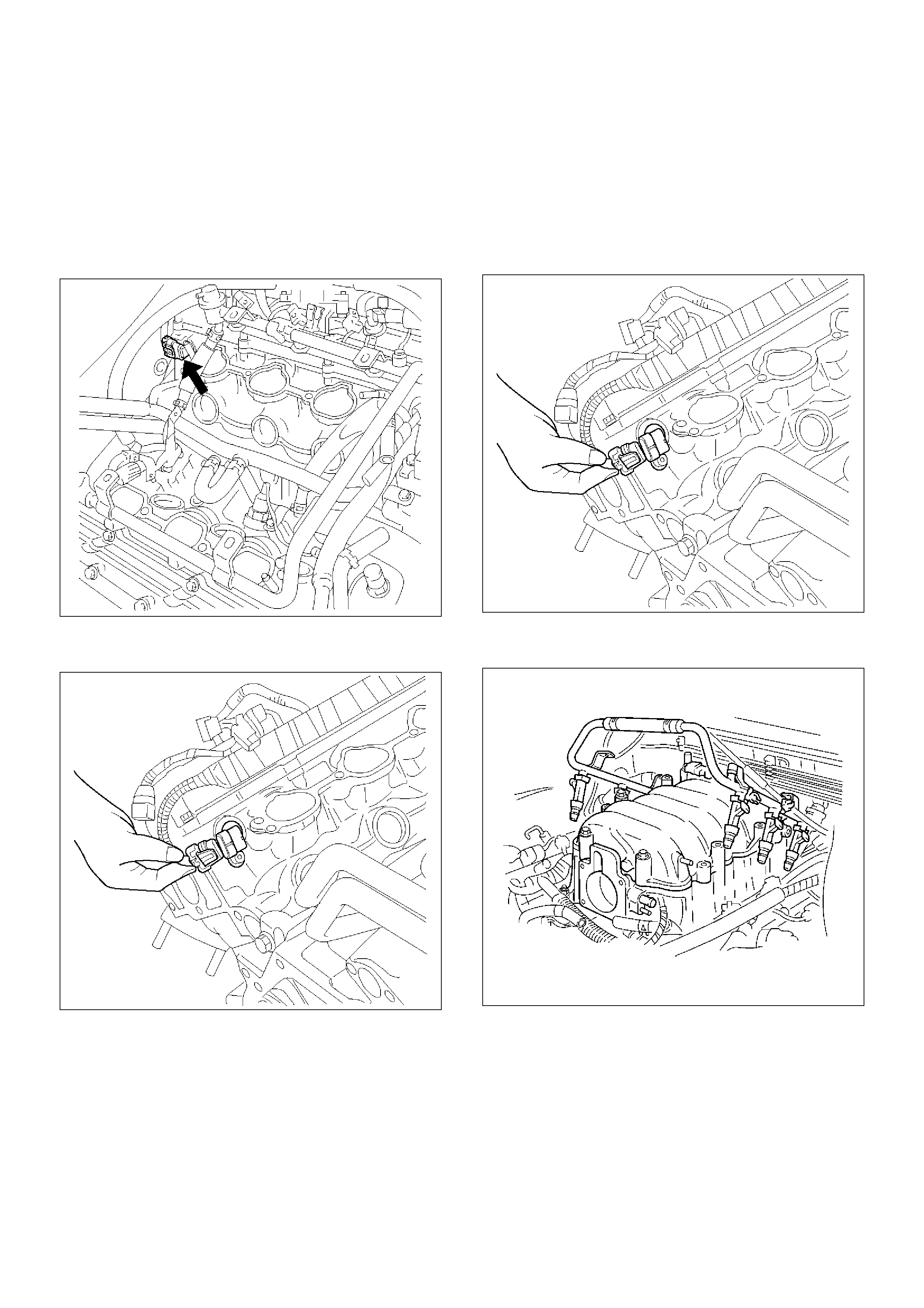
Camshaft Position (CMP) Sensor
Removal Procedure
1.Disconnect the negative battery cable.
2.Remove the engine cover.
3.Remove the common chamber assembly.
Refer to Common Chamber in Engine Mechanical.
014RW120
4.Disconnect the electrical connector to the CMP
sensor.
014RV053
5.Remove the CMP retaining bolt from the side of left
cylinder head.
6.Remove the CMP sensor from the cylinder head.
Inspection Procedure
1.Inspect the sensor O-ring for cracks or leaks.
2.Replace the O-ring if it is worn or damaged.
3.Lubricate the new O-ring with engine oil.
4.Install the lubricated O-ring.
Installation Procedure
1.Install the CMP sensor in the cylinder head.
2.Install the CMP sensor retaining bolt.
Tighten
•Tighten the retaining screw to 9 N·m (78 lb in.).
3.Connect the electrical connector to the CMP sensor.
014RV053
4.Install the common chamber assembly.
Refer to Common Chamber in Engine Mechanical.
014RW106
5. Install the engine cover.
6. Connect the negative battery cable.
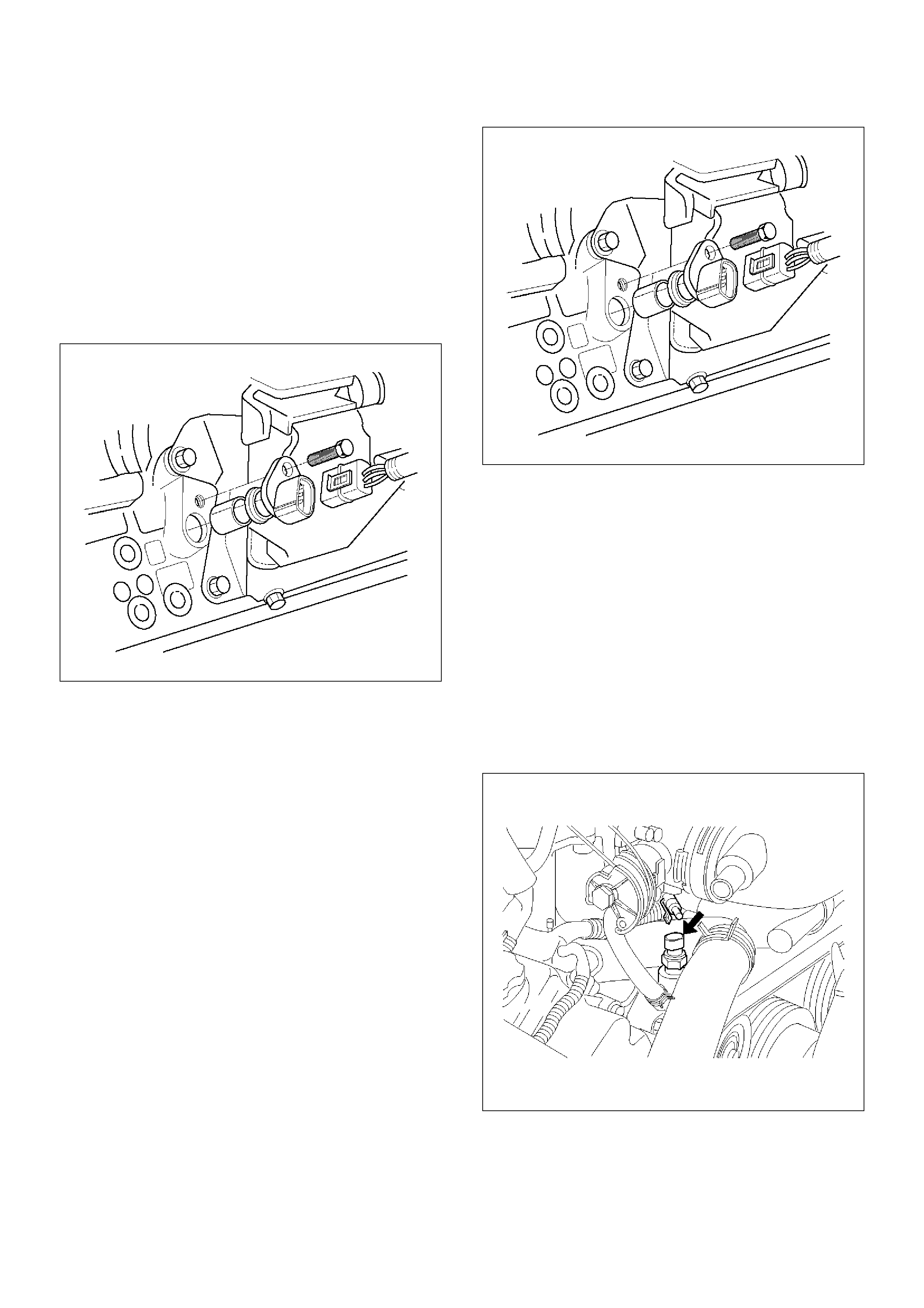
Crankshaft Position (CKP) Sensor
Removal Procedure
1.Disconnect the negative battery cable.
2.Disconnect the electrical connector to the CKP
sensor.
3.Remove one bolt and the CKP sensor from the right
side of the engine block, just behind the mount.
NOTE: Use caution to avoid any hot oil that might drip
out.
TS22909
Inspection Procedure
1.Inspect the sensor O-ring for cracks or leaks.
2.Replace the O-ring if it is worn or damaged.
3.Lubricate the new O-ring with engine oil.
4.Install the lubricated O-ring.
Installation Procedure
1.Install the CKP sensor in the engine block.
2.Install the CKP sensor mounting bolt.
Tighten
•Tighten the mounting bolt to 9 N·m (78 lb in.).
TS22909
3.Connect the electrical connector to the CKP sensor.
4.Connect the negative battery cable.
Engine Coolant Temperature (ECT) Sensor
Removal Procedure
NOTE: Care must be taken when handling the engine
coolant temperature (ECT) sensor. Damage to the ECT
sensor will affect proper operation of the fuel injection
system.
1.Disconnect the negative battery cable.
2.Drain the radiator coolant. Refer to Draining and
Refilling Cooling System in Engine Cooling.
3. Disconnect the electrical connector.
014RW127

4.Remove the ECT sensor from the coolant
crossover.
014RW086
Installation Procedure
1.Apply sealer or the equivalent to the threads of the
ECT sensor.
2.Install the ECT sensor in the coolant crossover.
Tighten
•Tighten the ECT sensor to 30 N·m (22 lb ft.).
014RW086
3.Connect the electrical connector.
014RW085
4.Fill the radiator with coolant. Refer to Draining and
Refilling Cooling System in Engine Cooling.
5. Connect the negative battery cable.
Heated Oxygen Sensor (HO2S)
Removal Procedure
1. Disconnect the negative battery cable.
2. Locate the oxygen sensors.
• Bank 1 sensor 1 is mounted on the right-hand
front exhaust pipe.
TS22912
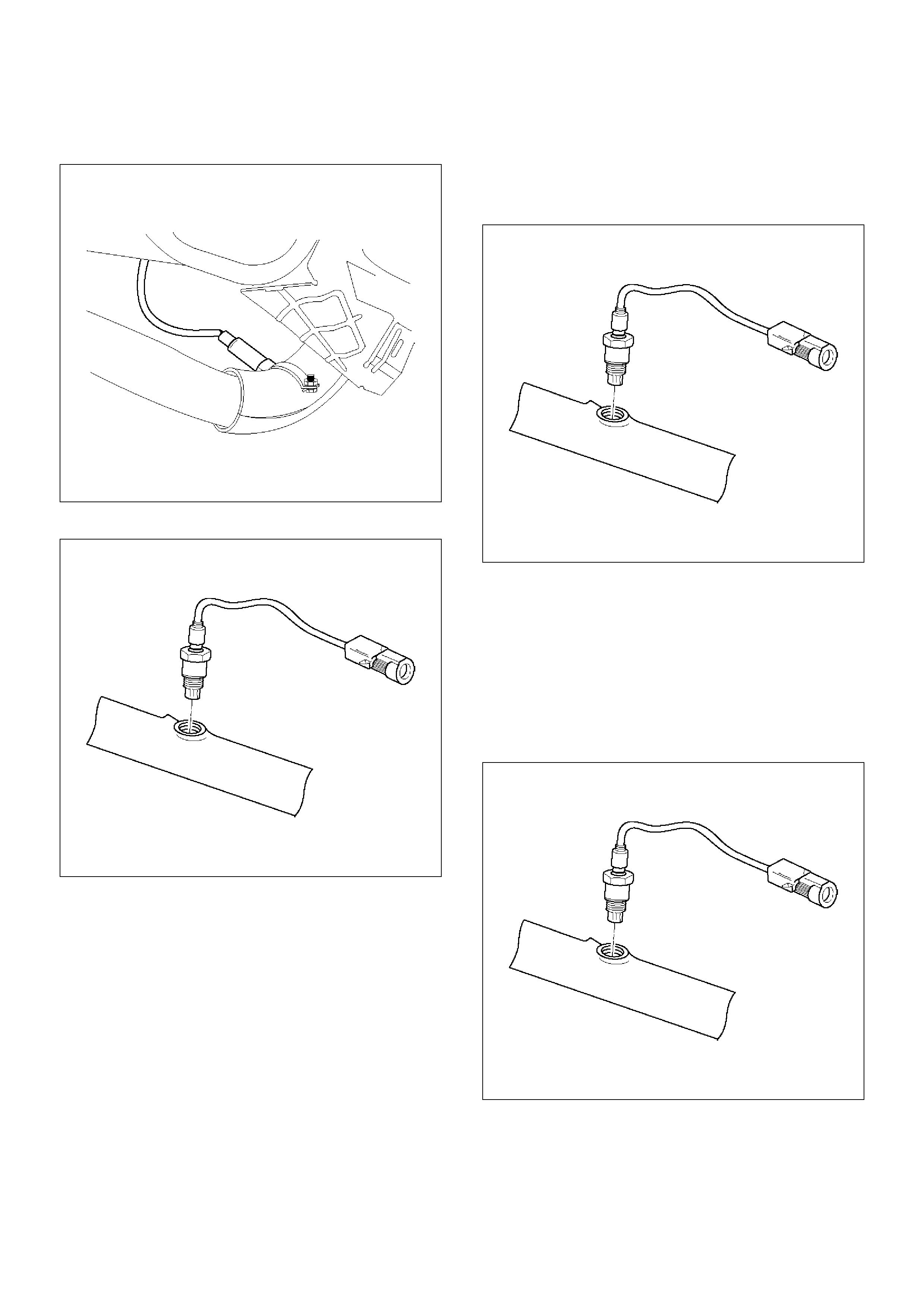
•Bank 2 sensor 1 is mounted on the exhaust pipe
ahead of the catalytic converter.
TS22914
3.Disconnect the pigtail from the wiring harness.
TS23739
Important: The pigtail is permanently attached to the
sensor. Be careful not to pull the wires out.
NOTE: Do not use a torch to remove an HO2S unless
the sensor is being replaced. Using a torch could
damage the sensor.
4. Remove the sensor from the exhaust pipe.
• Because of the expansion and contraction of the
metal in the exhaust system over time, this may
be difficult if the engine temperature is below
48°C (120°F).
TS23739
Inspection Procedure
All two sensors are identical. Inspect each in the same
way.
1. Inspect the pigtail and the electrical connector for
grease, dirt, corrosion, and bare wires or worn
insulation.
2. Inspect the louvered end of the sensor for grease,
dirt, or other contaminations.
TS23739

Installation Procedure
Important:
• A special anti-seize compound, P/N 5613695, is used
on the HO2S threads. This compound consists of
glass beads suspended in a liquid graphite solution.
The graphite burns away with engine heat, but the
glass beads will remain, making the sensor easier to
remove.
• New or service sensors will already have the
compound applied to the threads. If a sensor is
removed and is to be reinstalled for any reason, the
threads must have anti-seize compound applied.
1. Apply anti-seize compound or the equivalent to the
threads of the oxygen sensor, if necessary.
2. Install the oxygen sensor on the exhaust pipe in its
original position.
Tighten
• Tighten the oxygen sensor to 55 N·m (40 lb in.).
TS23739
3. Connect the pigtail to the wiring harness.
4. Connect the negative battery cable.
Intake Air Temperature (IAT) Sensor
Removal Procedure
1. Disconnect the negative battery cable.
2. Remove the engine cover
3. The IAT sensor is located in the intake air duct,
behind the throttle body.
4. Disconnect the electrical connector from the IAT
sensor.
TS23741
5. Remove the IAT sensor from the intake air duct by
using a rocking motion while pulling the sensor.
Installation Procedure
1. Install the IAT sensor into the grommet in the intake
air duct.
2. Correct the IAT electrical connector.
TS23741
3. Install the engine cover.
4. Connect the negative battery cable.
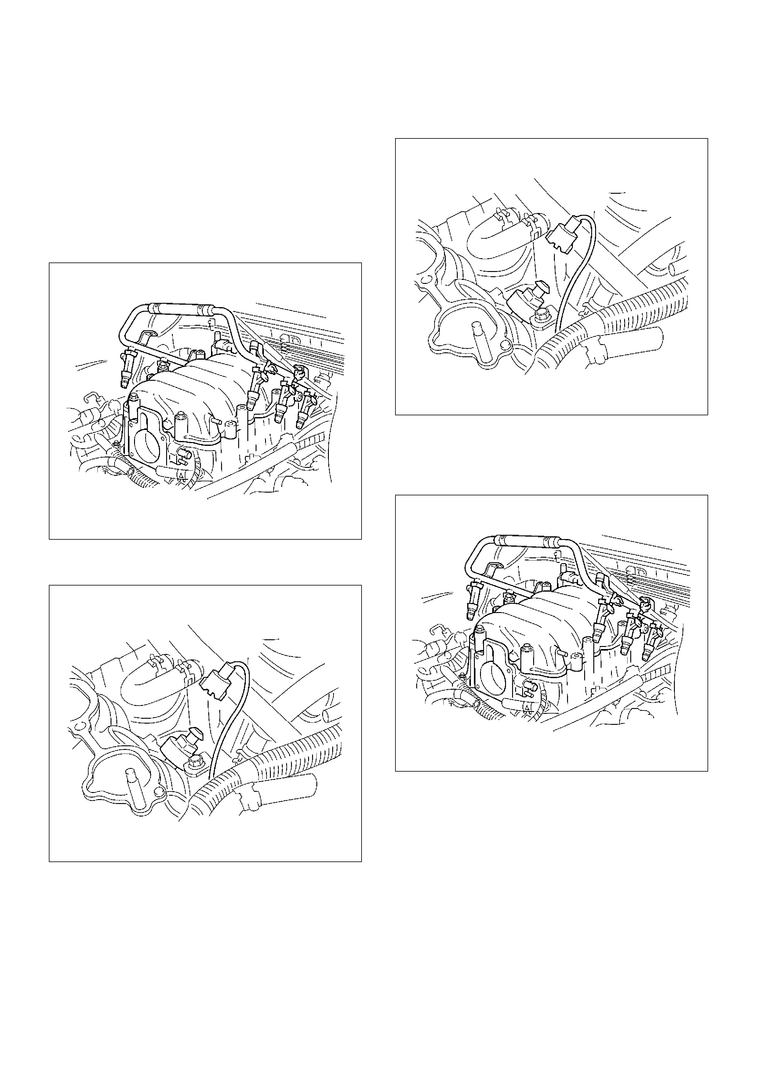
Knock Sensor (KS)
Removal Procedure
1.Disconnect the negative battery cable.
2.Drain the cooling system. Refer to Draining and
Filling the Cooling System in Engine Cooling.
3.Remove the engine cover.
4.Remove the common chamber assembly.
Refer to Common Chamber in Engine Mechanical.
014RW106
5.Disconnect the electrical connector from the knock
sensor.
014RW103
6.Unscrew the knock sensor from the engine block.
Installation Procedure
NOTE: Do not apply thread sealant to the sensor
threads. The sensor is coated at the factory and
applying additional sealant will affect the sensor's ability
to detect detonation.
1.Screw the knock sensor into the engine block.
Tighten
•Tighten the knock sensor to 20 N·m (177 lb in.).
014RW103
2.Connect the electrical connector to the knock
sensor.
3.Install the common chamber assembly.
Refer to Common Chamber in Engine Mechanical.
014RW106
4.Install the engine cover.
5.Fill the cooling system.
Refer to Draining and Filling the Cooling System in
Engine Cooling.
6. Connect the negative battery cable.
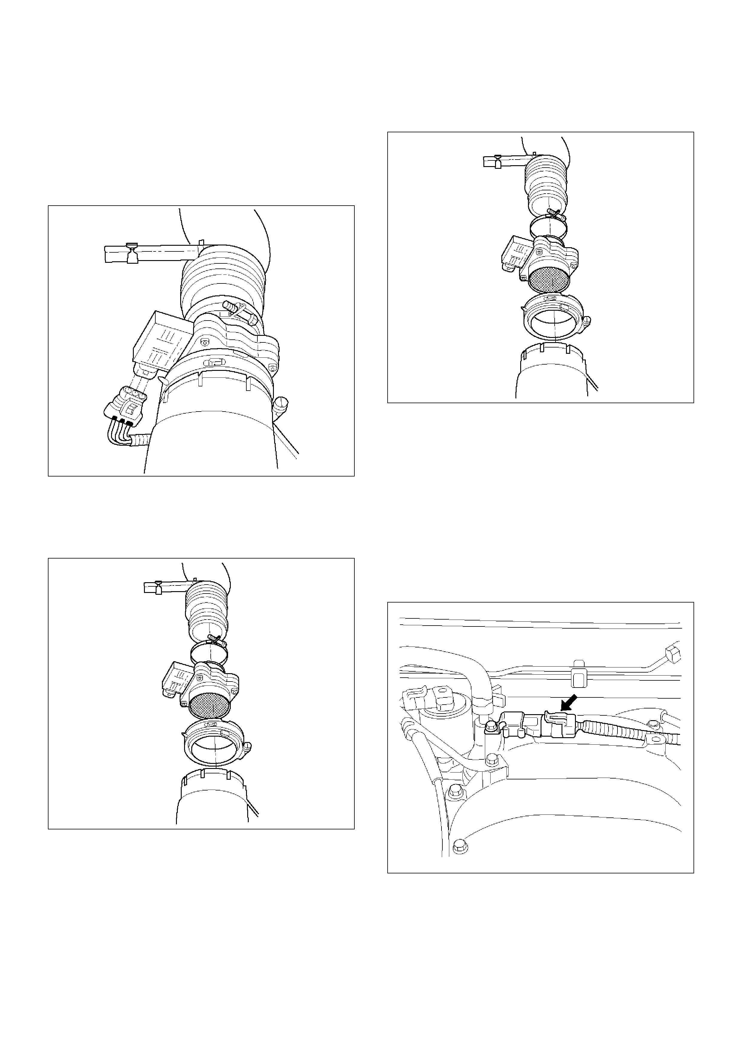
Mass Air Flow (MAF) Sensor
Removal Procedure
1. Disconnect the negative battery cable.
2. Disconnect the electrical connector from the MAF
sensor.
TS23740
3. Loosen the clamps which secure the intake air duct
and the air cleaner to the MAF sensor.
4. Remove the intake air duct from the MAF sensor.
5. Remove the MAF sensor from the air cleaner.
TS23781
Installation Procedure
1. Install the MAF sensor on the air cleaner with the
clamp.
2. Install the intake air duct and the clamp on the MAF
sensor.
TS23781
3. Tighten the clamps to secure the MAF sensor to the
intake air duct and the air cleaner.
4. Connect the MAF electrical connector.
5. Connect the negative battery cable.
Manifold Absolute Pressure (MAP) Sensor
Removal Procedure
1. Disconnect the negative battery cable.
2. Disconnect the electrical connector from the MAP
sensor.
055RW005
3. Remove the bolt securing the MAP sensor to the
mounting bracket on the common chamber.
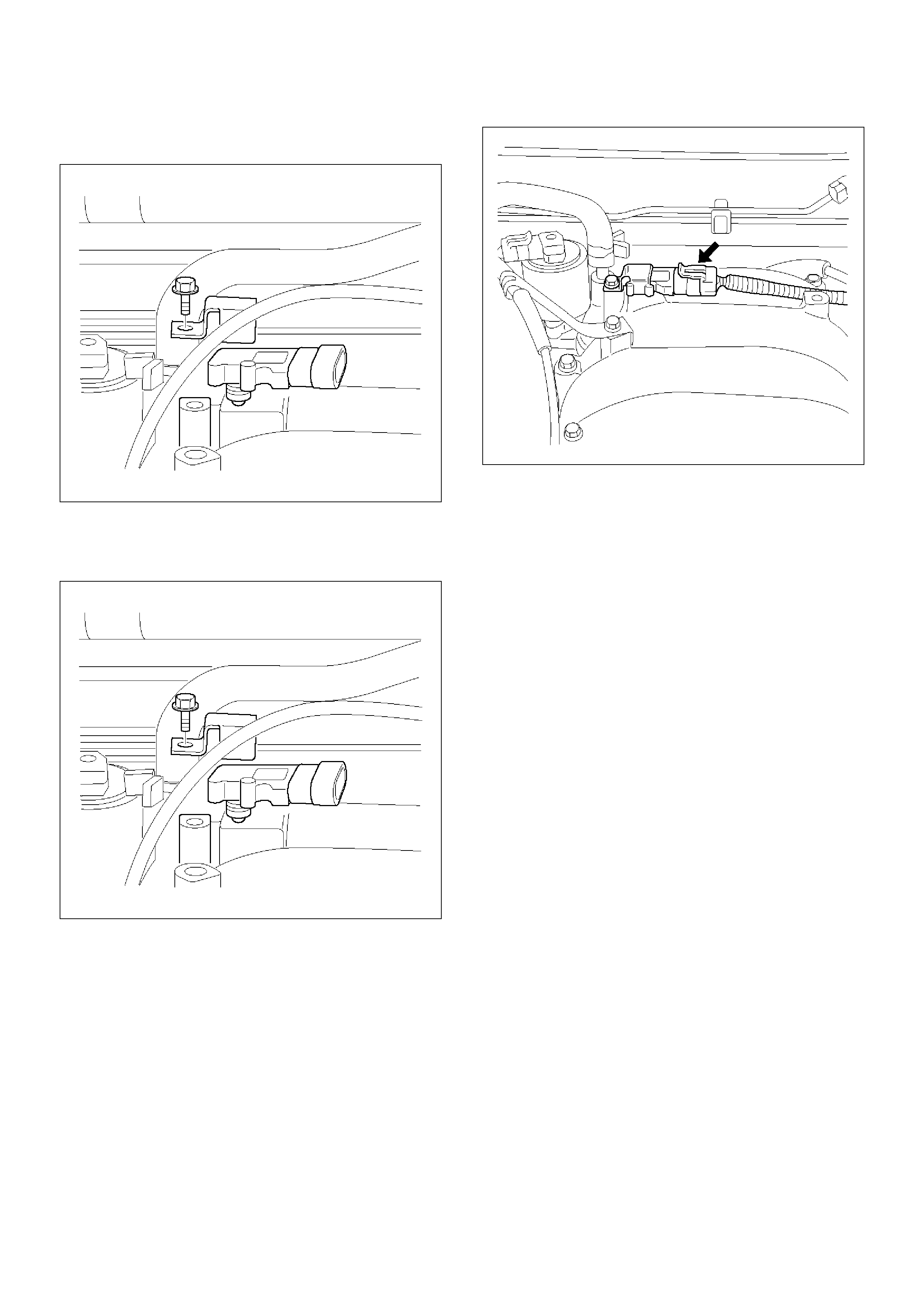
4.Remove the MAP sensor from the mounting
bracket.
055RW002
Installation Procedure
1.Install the MAP sensor in the mounting bracket.
055RW002
2.Install the mounting bracket retaining bolt on the
common chamber.
3.Connect the MAP electrical connector.
055RW005
4.Connect the negative battery cable.
Malfunction Indicator Lamp (MIL)
Removal and Installation Procedure
Refer to Warning light bulb, indicator light valve,
illumination light bulb, A/T indicator light bulb in Meter
and Gauge.
Powertrain Control Module (PCM)
Service Precaution
NOTE: To prevent possible electrostatic discharge
damage to the PCM, do not touch the connector pins or
soldered components on the circuit board.
Electrostatic Discharge (ESD) Damage
Electronic components used in the control systems are
often designed to carry very low voltage. Electronic
components are susceptible to damage caused by
electrostatic discharge. Less than 100 volts of static
electricity can cause damage to some electronic
components. By comparison, it takes as much as 4,000
volts for a person to even feel the zap of a static
discharge.
There are several ways for a person to become
statically charged. The most common methods of
charging are by friction and by induction. An example of
charging by friction is a person sliding across a car seat.
Charging by induction occurs when a person with well
insulated shoes stands near a highly charged object
and momentarily touches ground. Charges of the same
polarity are drained off leaving the person highly
charged with the opposite polarity. Static charges can
cause damage, therefore, it is important to use care
when handling and testing electronic components.
NOTE: To prevent possible Electrostatic Discharge
damage, follow these guidelines:
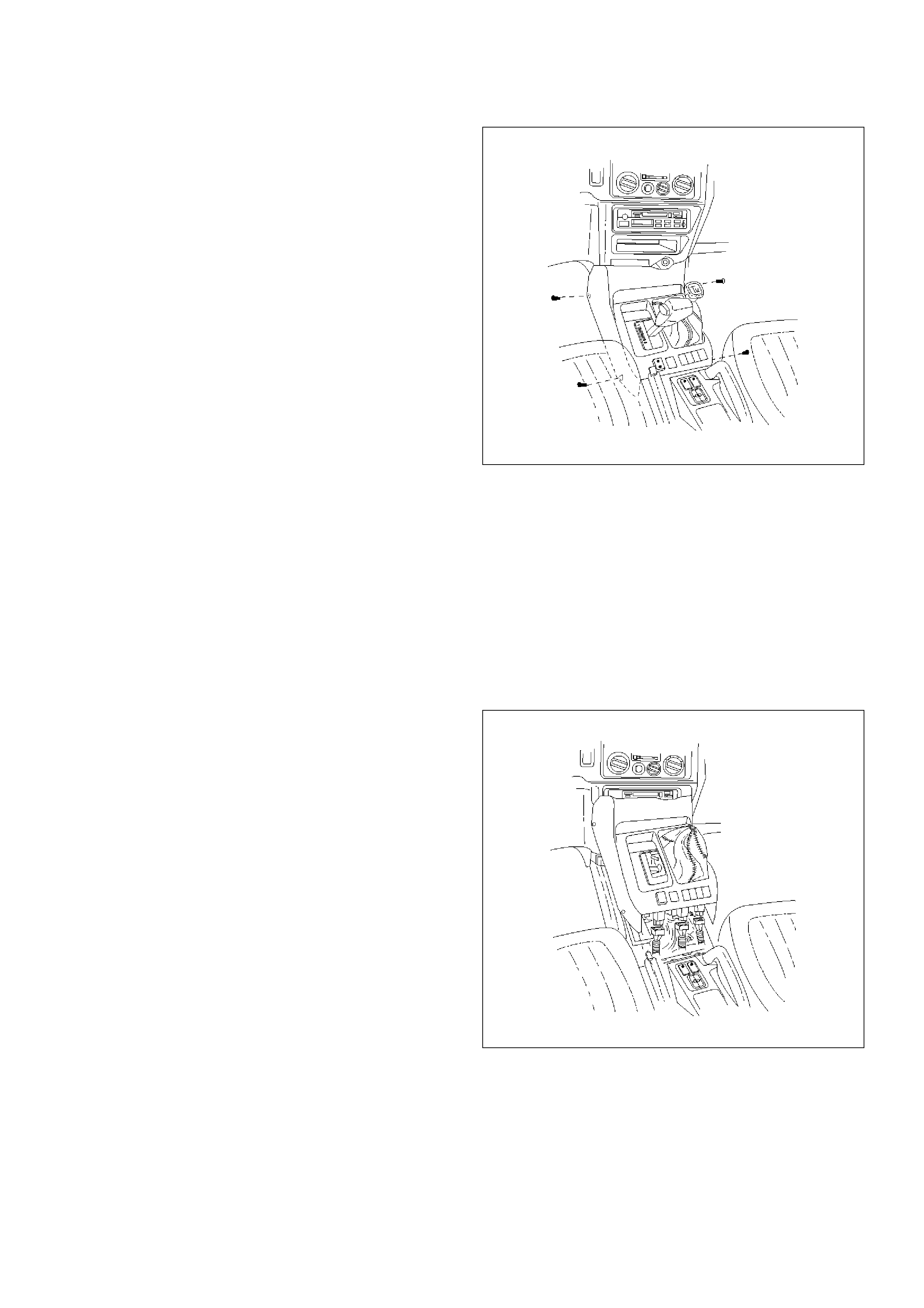
•Do not touch the control module connector pins or
soldered components on the control module circuit
board.
•Do not open the replacement part package until the
part is ready to be installed.
•Before removing the part from the package, ground
the package to a known good ground on the vehicle.
•If the part has been handled while sliding across the
seat, or while sitting down from a standing position, or
while walking a distance, touch a known good ground
before installing the part.
NOTE: To prevent internal PCM damage, the ignition
must be in the “OFF” position in order to disconnect or
reconnect power to the PCM (for example: battery
cable, PCM pigtail, PCM fuse, jumper cables, etc.).
Important: When replacing the production PCM with a
service PCM, it is important to transfer the broadcast
code and production PCM number to the service PCM
label. This will allow positive identification of PCM parts
throughout the service life of the vehicle. Do not record
this information on the metal PCM cover.
Important: The ignition should always be in the “OFF”
position in order to install or remove the PCM
connectors.
Service of the PCM should normally consist of either
replacement of the PCM or EEPROM programming. If
the diagnostic procedures call for the PCM to be
replaced, the PCM should be checked first to ensure it
is the correct part. If it is, remove the faulty PCM and
install the new service PCM.
The service PCM EEPROM will not be programmed.
DTC P0601 indicates the check sum error.
Removal Procedure
1. Disconnect the negative battery cable.
2. Block the wheels.
3. Remove the front console assembly.
1. Remove the four screws.
TS23755
2. Remove the transfer shift lever knob by
unscrewing the knob.
3. Move the transmission gear selector out of the
park position.
4. Lift up sharply on the back edge of the
assembly.
5. Disconnect the seat heater switch connectors (if
equipped).
6. Disconnect the POWER and WINTER switch
connectors.
7. Lift out the front console assembly.
TS23756
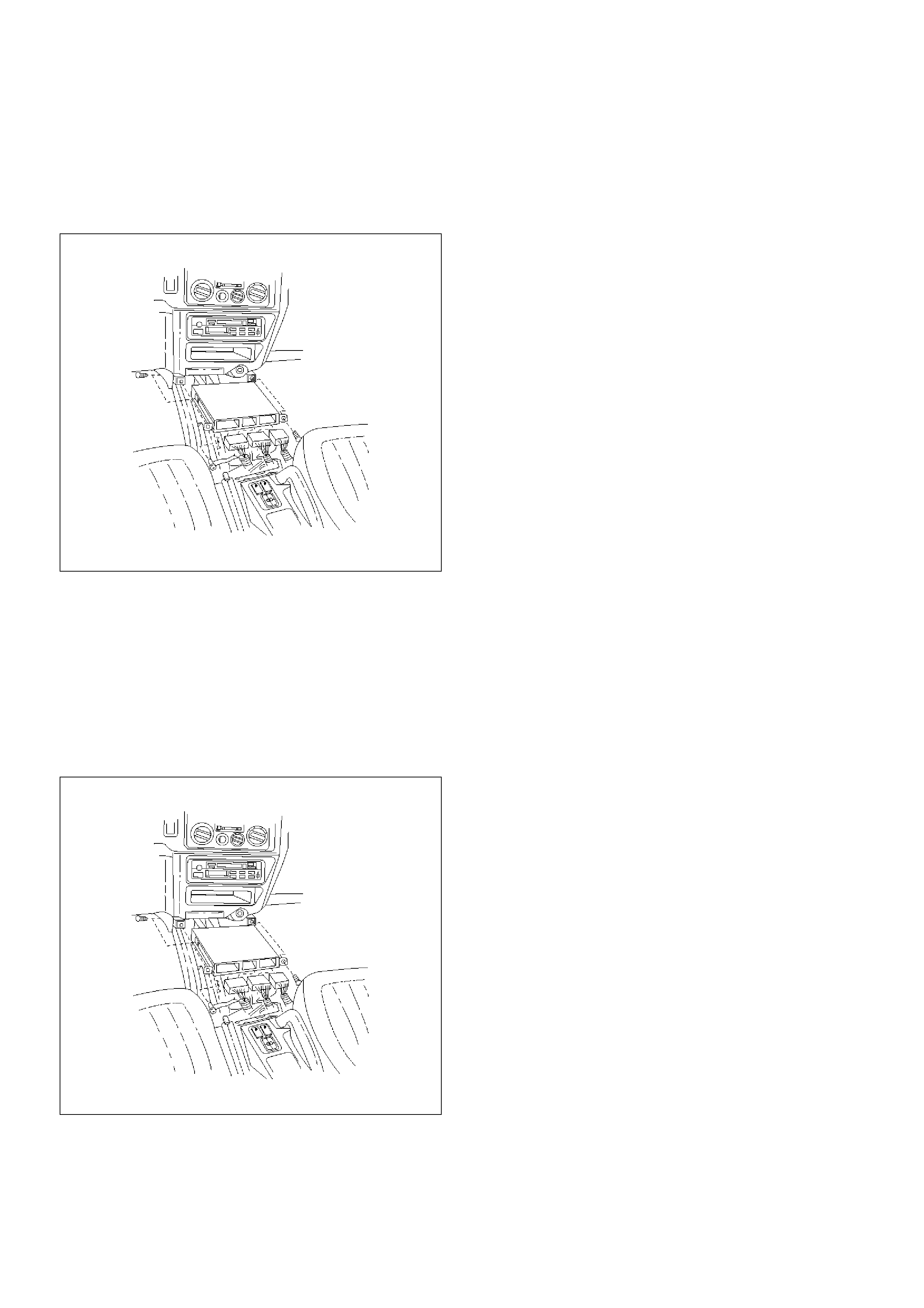
4. Disconnect the red, white, and blue electrical
connectors at the PCM.
5. Remove the two screws in the front of the PCM.
6. Remove the one screw at the left rear of the PCM.
7. Pull the PCM straight out from the dashboard.
TS23757
Installation Procedure
1. Insert the PCM into the dashboard.
• Line up the holes in front for the mounting
screws.
2. Install the PCM with two screws in the front and one
screw at the left rear.
3. Plug the red, white, and blue connectors into the
appropriate sockets.
TS23757
EEPROM
General Description
The Electronically Erasable Programmable Read Only
Memory (EEPROM) is a permanent memory that is
physically soldered within the PCM. The EEPROM
contains program and calibration information that the
PCM needs to control powertrain operation.
EEPROM Programming
1. Step-up – Ensure that the following conditions have
been met:
• The battery is fully charged.
• The ignition is “ON.”
• The Vehicle Interface Module cable connection at
the DLC is secure.
2. Program the PCM using the latest software
matching the vehicle. Refer to up-to-date Techline
equipment user's instructions.
3. If the PCM fails to program, Refer to UBS 98 model
year Immobiliser Workshop Manual.
Functional Check
1. Perform the On-Board Diagnostic System Check.
2. Start the engine and run for one minute.
3. Scan for DTCs using the Tech 2.
Power Steering Pressure (PSP) Switch
General Description
The Power Steering Pressure (PSP) switch closes when
the hydraulic pressure reaches 3920 ± 690 kPa (570 ±
100 psi). This causes the PCM to actuate the idle air
control valve in order to prevent the additional load from
slowing down the engine. The switch opens when the
hydraulic pressure drops to 2970 ± 560 kPa (430 ± 80
psi).
Removal Procedure
1. Disconnect the PSP switch pigtail from the wiring
harness.
• The pigtail is permanently attached to the switch.
Do not attempt to remove the wires from the
sensor.
• Have a container ready to catch the power
steering fluid that leaks out of the line when the
switch is removed.
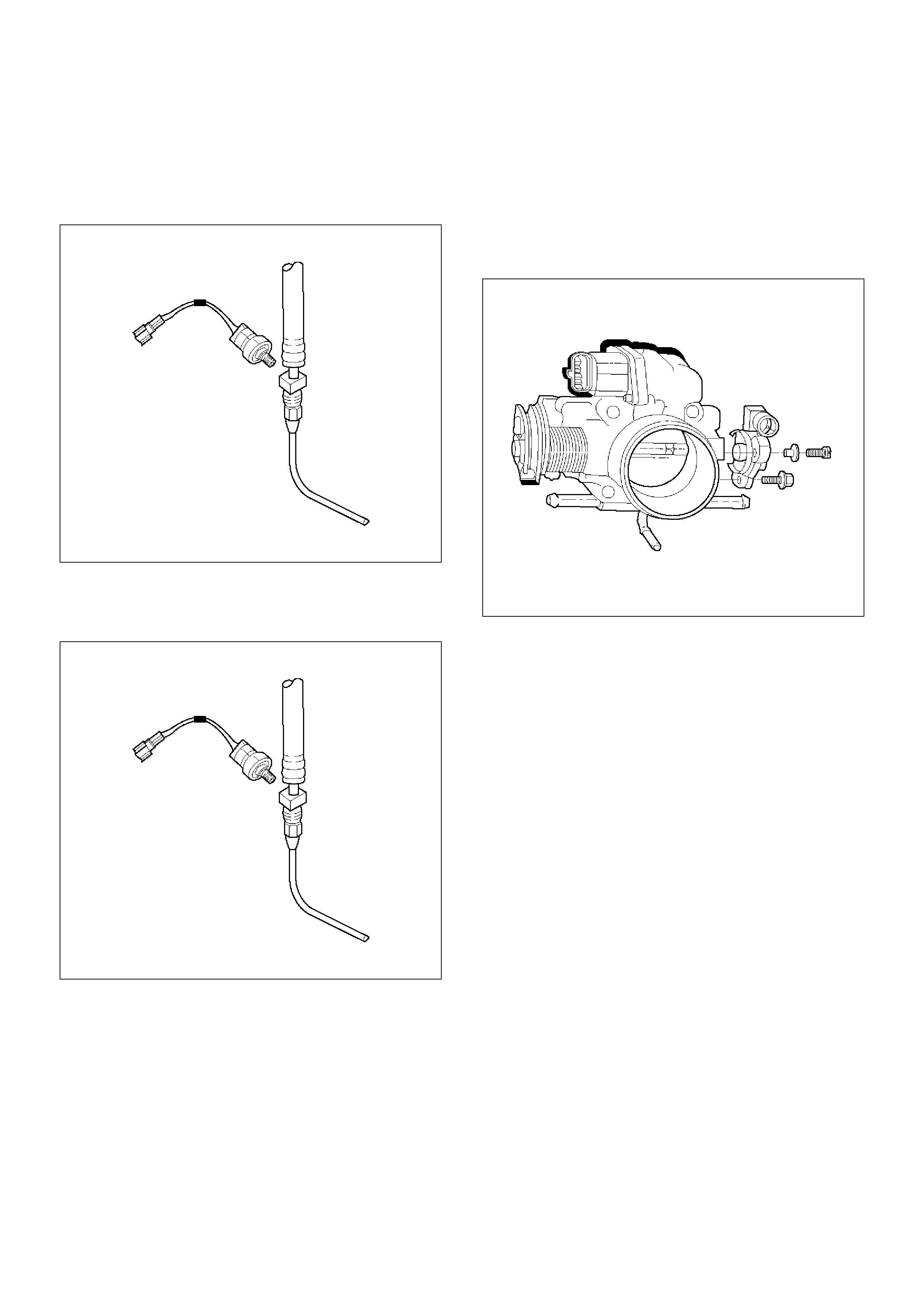
2.Remove the PSP switch from the power steering
line.
•Plug the line to prevent excessive loss of fluid
and possible contamination of the power steering
system.
TS23760
Installation Procedure
1.Install the PSP switch in the power steering line.
TS23760
2.Connect the PSP switch pigtail to the wiring
harness.
3.Check the power steering fluid level. Refer to
Power Steering.
4.Start the engine. Watch the PSP switch for signs of
fluid leakage.
Throttle Position (TP) Sensor
Removal Procedure
1.Disconnect the negative battery cable.
2.Disconnect the TPS electrical connector.
3.Remove the bolts and the TP sensor from the
throttle body.
TS23747
NOTE: Do not clean the TP sensor by soaking it in
solvent. The sensor will be damaged as a result.
Function Check
Use a Tech 2 to check the TP sensor output voltage at
closed throttle.
•The voltage should be under 0.85 volt.
•If the reading is greater than 0.85 volt, check the
throttle shaft to see if it is binding. Check that the
throttle cable is properly adjusted, also. Refer to
Throttle Cable Adjustment.
• If the throttle shaft is not binding and the throttle cable
is properly adjusted, install a new TP sensor.
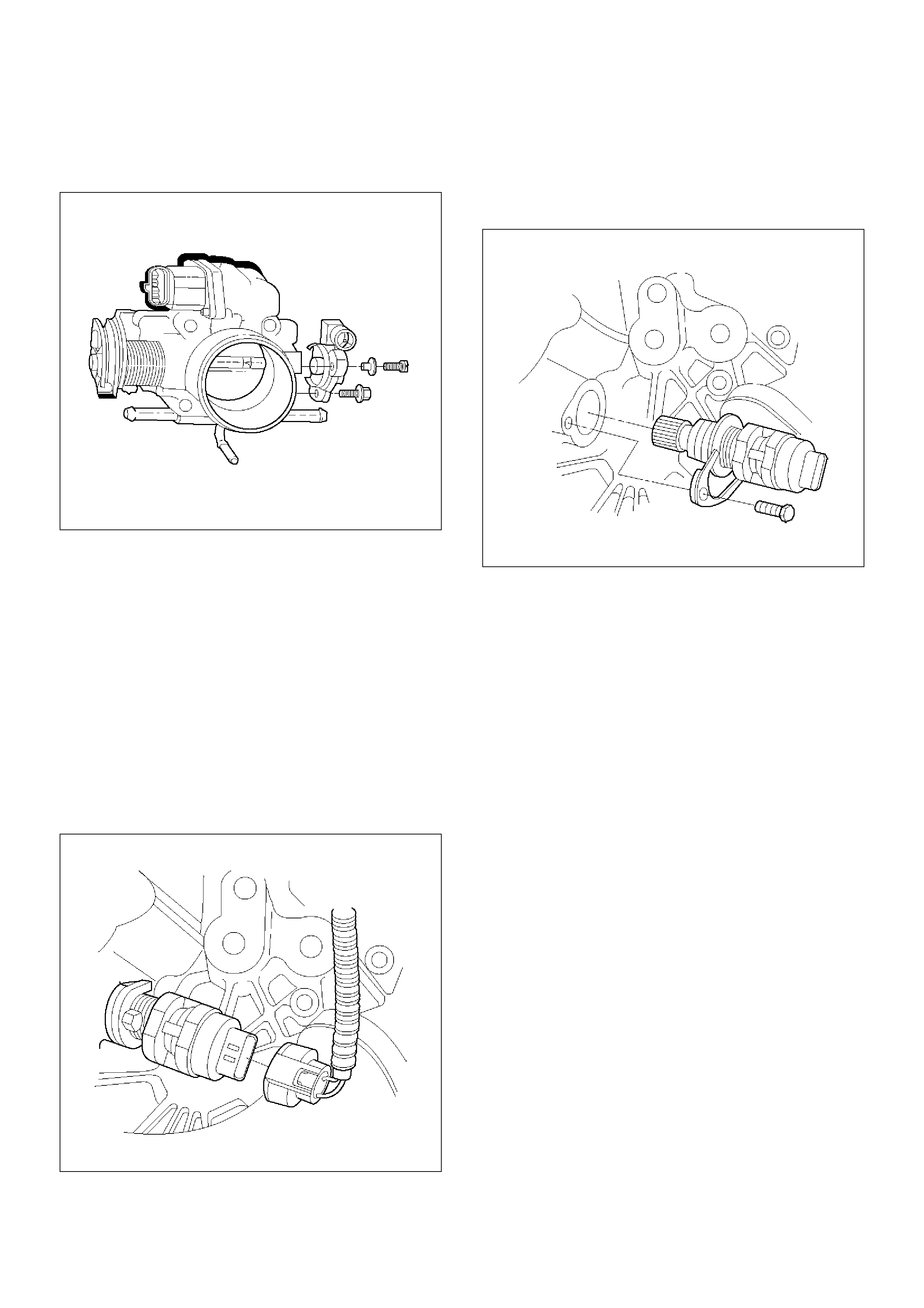
Installation Procedure
1.Install the TP sensor on the throttle body with the
bolts.
TS23747
2.Connect the TP electrical connector.
3.Install the negative battery cable.
Vehicle Speed Sensor (VSS)
Removal Procedure
CAUTION: The VSS is located on the right side of
the transfer case just ahead of the rear propeller
shaft and very close to the exhaust pipes. Be sure
that the exhaust pipes are cool enough to touch
before trying to remove the VSS. If the pipes are
hot, you could be burned.
1.Disconnect the negative battery cable.
2.Disconnect the VSS electrical connector.
TS23748
3.Remove the bolt and the clamp securing the VSS in
place.
Important: Have a container ready to catch any fluid
that leaks out when the VSS is removed from the
transfer case.
TS23780
4. Remove the VSS from the transfer case by wiggling
it slightly and pulling it straight out.
Inspection Procedure
1. Inspect the electrical connector for signs of
corrosion or warping. Replace the VSS if the
electrical connector is corroded or warped.
2. Inspect the VSS driven gear for chips, breaks, or
worn condition. Replace the VSS if the driven gear
is chipped, broken or worn.
3. Inspect the O-ring for wear, nicks, tears, or
looseness. Replace the O-ring if necessary.
Installation Procedure
1. Install the VSS in the transfer case with the notch for
the connector facing the rear.
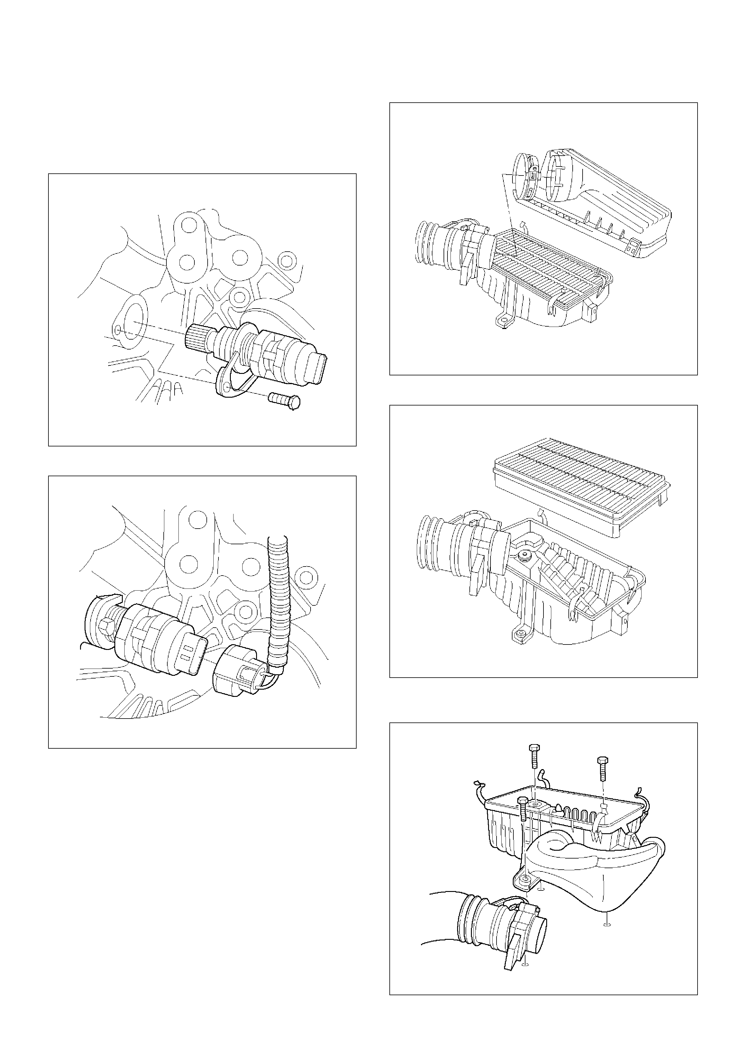
2. Secure the VSS in place with the clamp and the
bolt.
Tighten
• Tighten the bolt to 16 N·m (12 lb ft.).
TS23780
3. Connect the VSS electrical connector.
TS23748
4. Check the transfer case oil level. Add fluid if
necessary.
5. Connect the negative battery cable.
Air Cleaner/Air Filter
Removal Procedure
1. Loosen the clamp between the air cleaner lid and
the mass air flow sensor.
2. Release the four latches securing the lid to the air
cleaner housing.
3. Remove the air cleaner lid.
TS23973
4. Remove the air filter element.
TS23794
5. Remove the retaining bolts and the air cleaner
housing from the vehicle.
130RT002
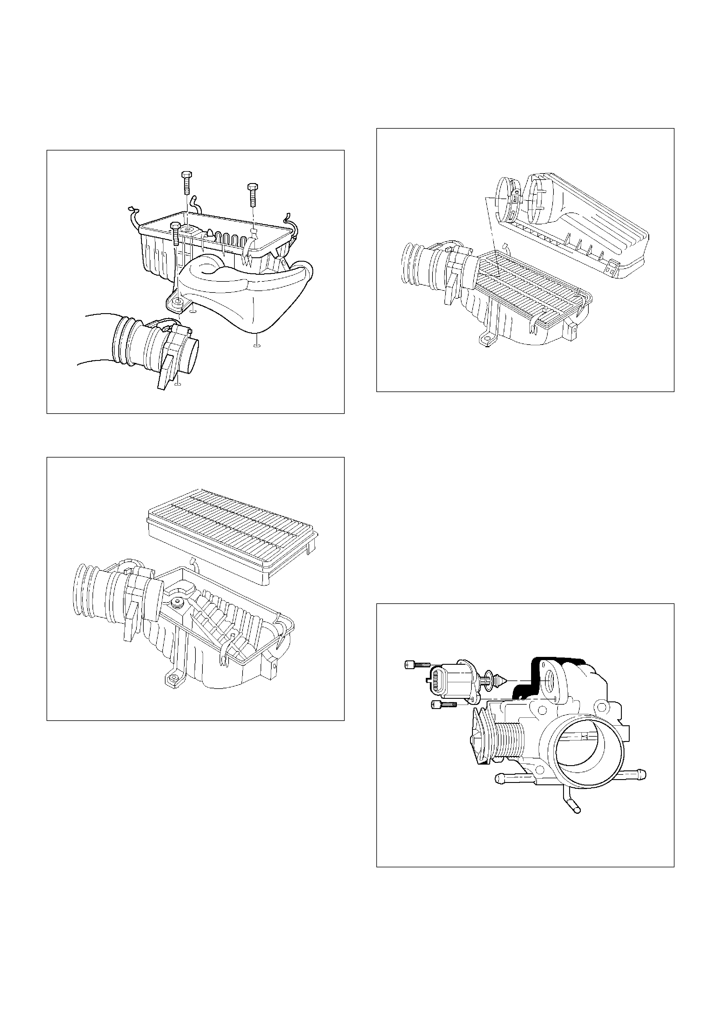
Installation Procedure
1. Install the air cleaner housing in the vehicle with the
retaining bolts.
130RT002
2. Install the air filter element in the air cleaner
housing.
TS23794
3. Install the air cleaner lid on the MAF sensor and the
air cleaner housing.
TS23973
4. Tighten the clamp and secure the four latches
between the lid and the air cleaner housing.
Idle Air Control (IAC) Valve
Removal Procedure
1. Disconnect the negative battery cable.
2. Disconnect the IAC electrical connector.
3. Remove the bolts and the IAC valve from the throttle
body.
NOTE: Do not clean the IAC valve by soaking it in
solvent. The valve will be damaged as a result.
TS23745
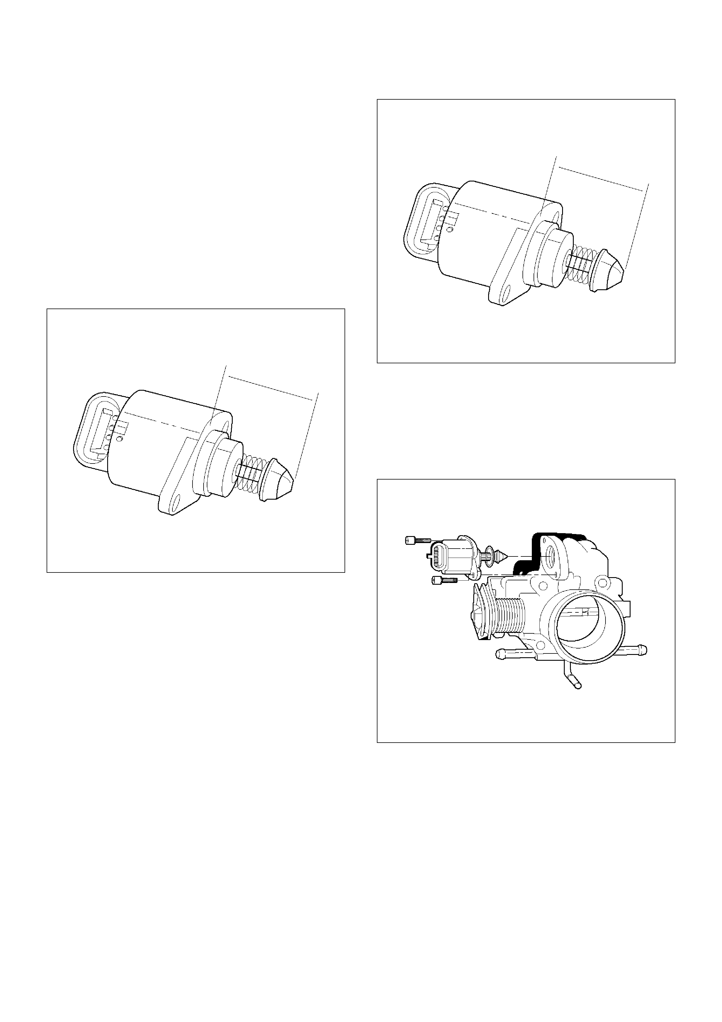
Cleaning, Inspection, and Measurement
Procedure
•Clean the IAC valve O-ring sealing surface, pintle
valve seat and air passage.
–Use carburetor cleaner and a parts cleaning brush
to remove carbon deposits. Do not use a cleaner
that contains methyl ethyl ketone. This is an
extremely strong solvent and not necessary for this
type of deposit.
–Shiny spots on the pintle are normal and do not
indicate misalignment or a bent pintle shaft.
–If the air passage has heavy deposits, remove the
throttle body for complete cleaning.
TS23746
•Inspect the IAC valve O-ring for cuts, cracks, or
distortion. Replace the O-ring if damaged.
•In order to install a new IAC valve, measure the
distance between the tip of the pintle and the
mounting flange. If that measurement is 28 mm (1.1
in.) or less, the valve needs no adjustment. If the
measurement is greater than 28 mm (1.1 in.), apply
finger pressure and retract the valve. The force
required to retract the pintle on a new valve will not
damage the valve, shaft, or pintle.
NOTE: Do not push or pull on the IAC valve pintle on
IAC valves that have been in service. The force
required to move the pintle may damage it.
Important: Use an identical replacement part in order
to replace a valve. IAC valve pintle shape and diameter
are designed for the specific application.
TS23746
Installation Procedure
1.Install the IAC valve on the throttle body with the
bolts.
Tighten
•Tighten the bolts to 1 N·m (9 lb in.).
TS23745
2.Connect the IAC valve electrical connector.
3.Install the negative battery cable.
Common Chamber
Removal and Installation Procedure
Refer to Common Chamber in Engine Mechanical.
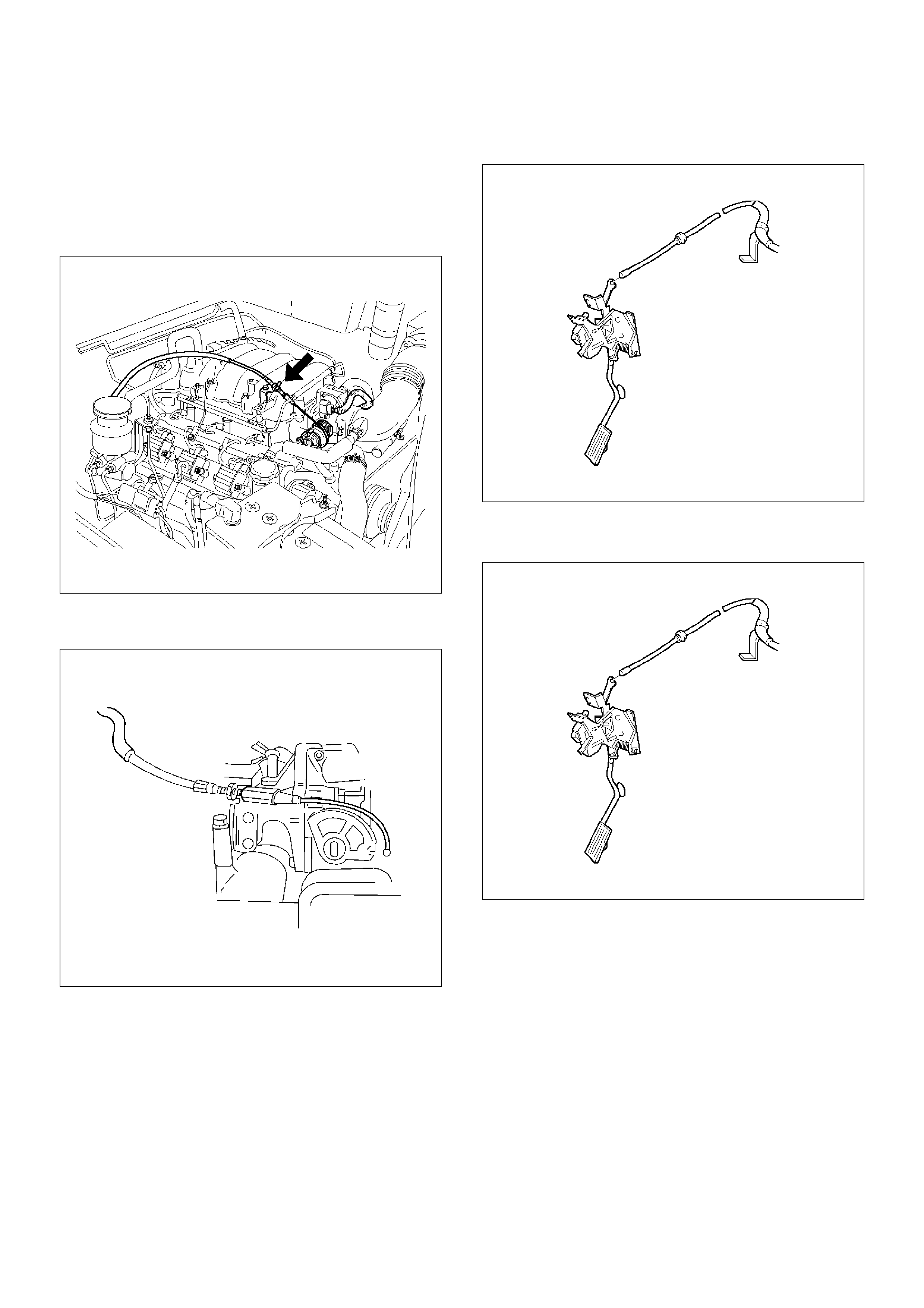
Accelerator Cable Assembly
Removal Procedure
1. Remove the engine cover.
2. Loosen the adjusting nut on the cable bracket
mounting on the common chamber.
101RW005
3. Remove the accelerator control cable (on the
throttle valve end).
101RW006
4. Remove the accelerator control cable (on the
accelerator pedal end).
TS23982
5. Remove the grommet.
6. Remove the accelerator control cable.
TS23983
Inspection Procedure
Check the following items, and replace the control cable
if any abnormality is found:
• The control cable should move smoothly.
• The control cable should not be bent or kinked.
• The control cable should be free of damage and
corrosion.
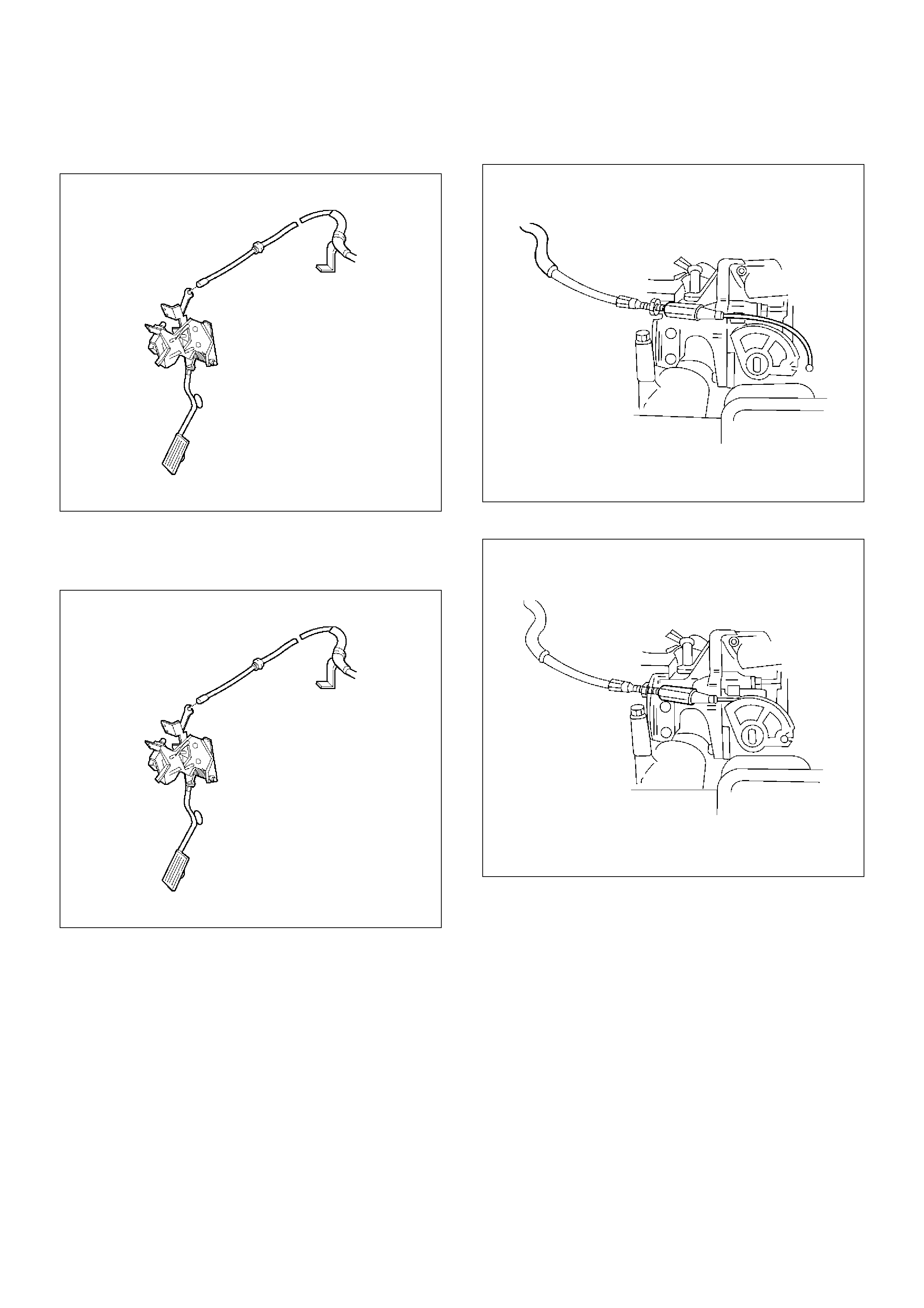
Installation Procedure
1.Install the accelerator control cable.
TS23983
2.Install the grommet.
3.Install the accelerator control cable (on the
accelerator pedal end).
TS23982
4.Install the accelerator control cable (on the throttle
valve end).
101RW006
5.Install the adjusting nut.
101RW007
6.Adjust the accelerator cable at the throttle body.
Refer to Accelerator Cable Adjustment .
7. Install the engine cover.
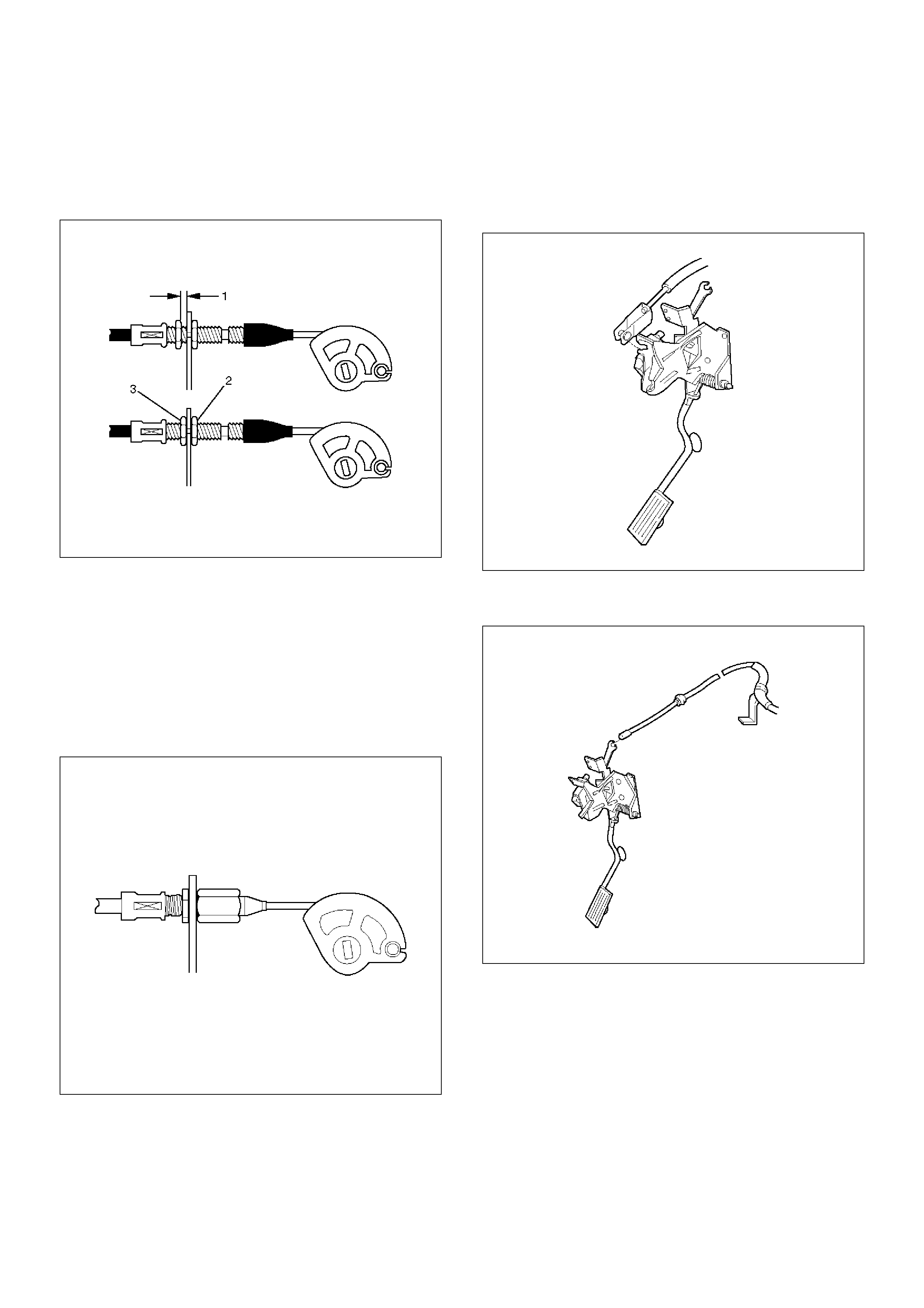
Adjustment Procedure
1.Loosen the adjusting nut and lock nut.
2.Pull outer cable closing fully the throttle valve.
3.Tighten adjusting nut and lock nut temporarily.
035RW004
4.Loosen adjusting nut by three turns and tighten lock
nut. Then, manually operating the throttle valve,
make sure that the valve lever returns up to the
stopper screw.
Important: The valve lever must return up to the
stopper screw. If the valve lever does not reach the
stopper screw, repeat the procedure again from step 1.
5. It does not reach the stopper screw, repeat from
step 1.
TS23782
Accelerator Pedal Replacement
Removal Procedure
1. Disconnect the cruise control cable from the
accelerator pedal assembly.
TS24053
2. Disconnect the accelerator pedal control cable from
the accelerator pedal assembly.
TS24054
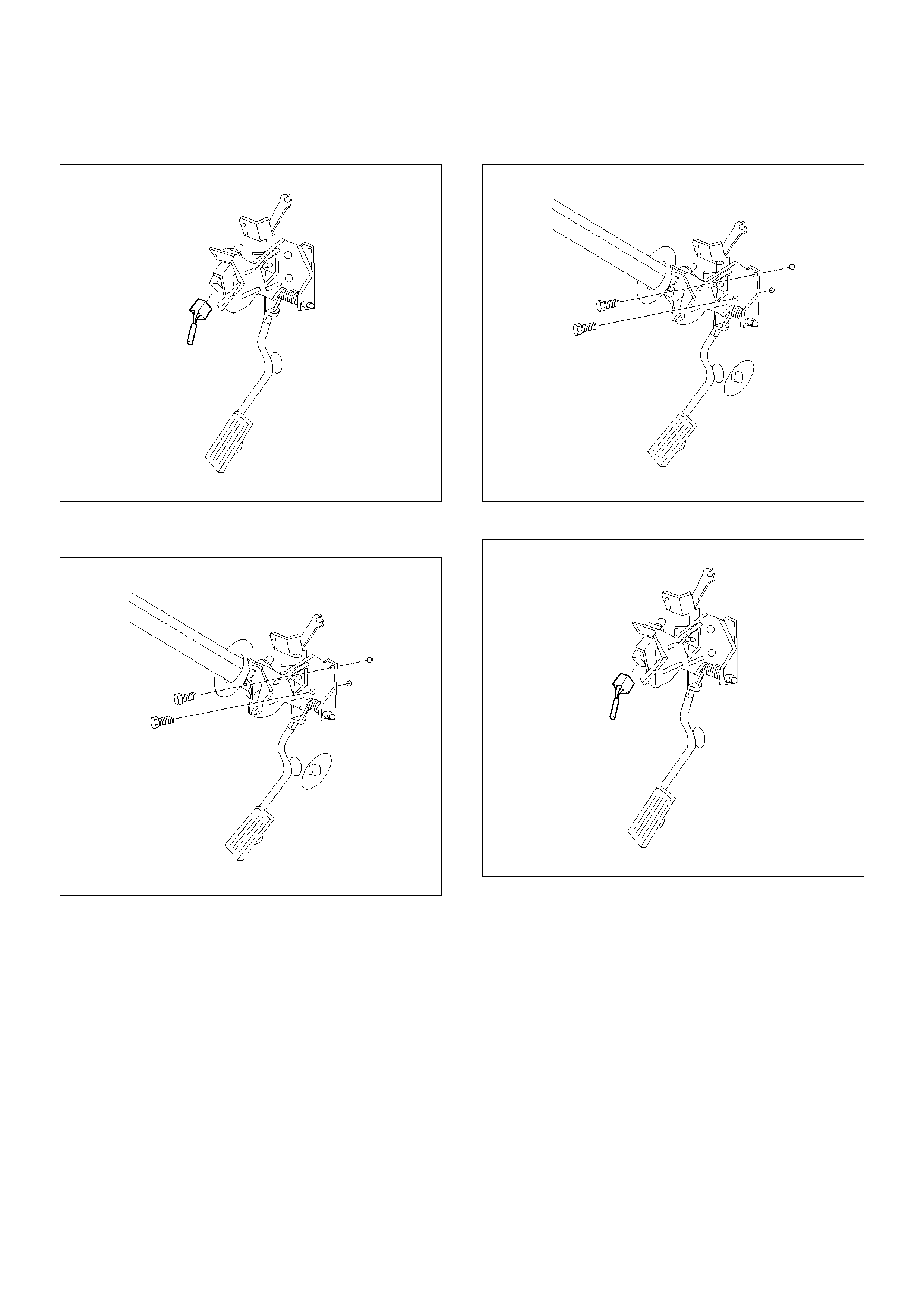
3. Disconnect the wiring harness from the kick-down
switch.
TS24038
4. Remove the two screws from the accelerator pedal
assembly.
TS24055
5. Remove the accelerator pedal assembly from the
bulkhead.
Installation Procedure
1. Install the accelerator pedal assembly on the
bulkhead.
2. Install the two screws to the accelerator pedal
assembly.
TS24055
3. Connect the wiring harness to the kick-down switch.
TS24038
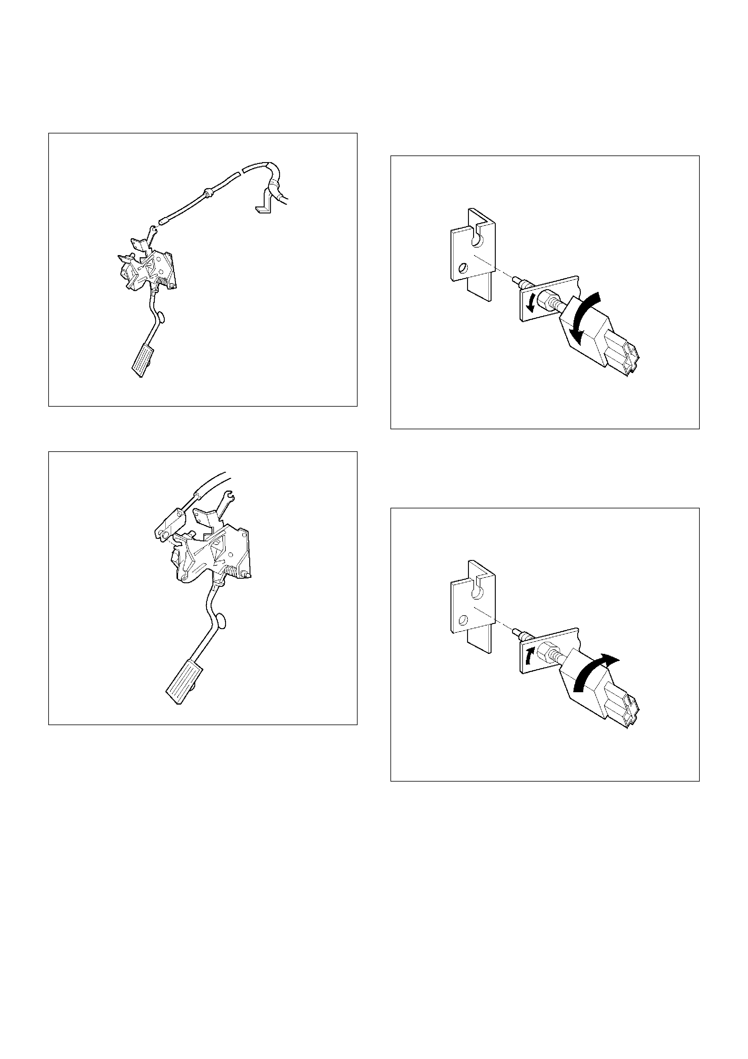
4. Connect the accelerator pedal control cable to the
accelerator pedal assembly.
TS24054
5. Connect the cruise control cable to the accelerator
pedal assembly.
TS24053
Pedal Stroke Adjustment Procedure
1. Loosen the jam nut and rotate the kick-down switch
counterclockwise.
TS24039
2. Fully depress the pedal and hold it by hand. Rotate
the switch clockwise until the switch clicks.
3. Rotate the switch 1/2 turn further and lock it in this
position by tightening the jam nut.
TS24040
4. Step on the accelerator pedal and make sure there
is a clicking sound at the full-stroke position.
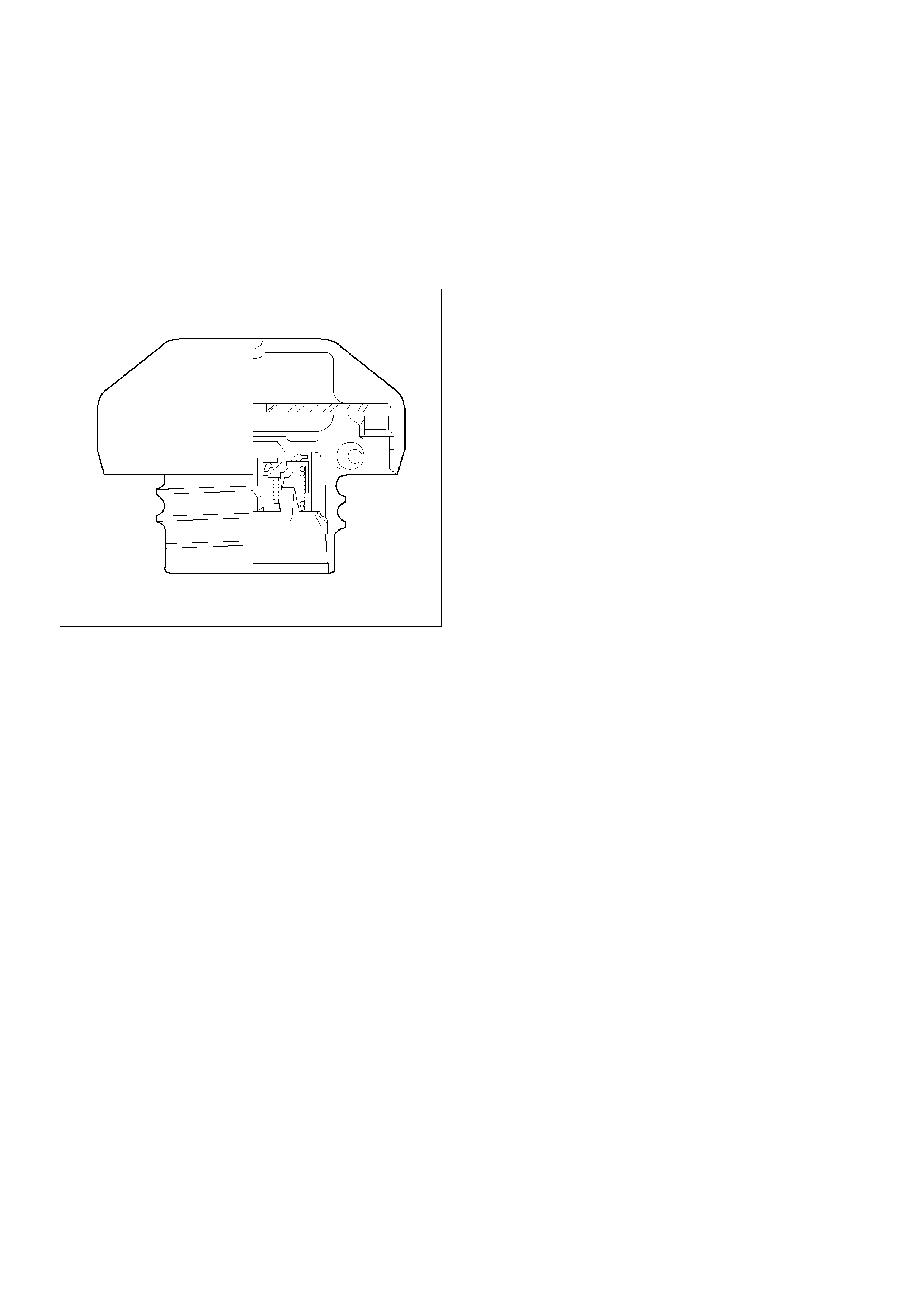
Fuel Filter Cap
General Description
The fuel filler cap includes a vacuum valve and a
pressure valve.
If high vacuum or high pressure occurs in the fuel tank,
each valve works to adjust the pressure in order to
prevent damage to the tank at the EGR valve.
TS23767
Inspection Procedure
NOTE: Replace the fuel filler cap with the same type of
filler cap that was originally installed on the vehicle.
• Check the seal ring in the filler cap for any
abnormality and for seal condition.
• Replace the filler cap if any abnormality is found.
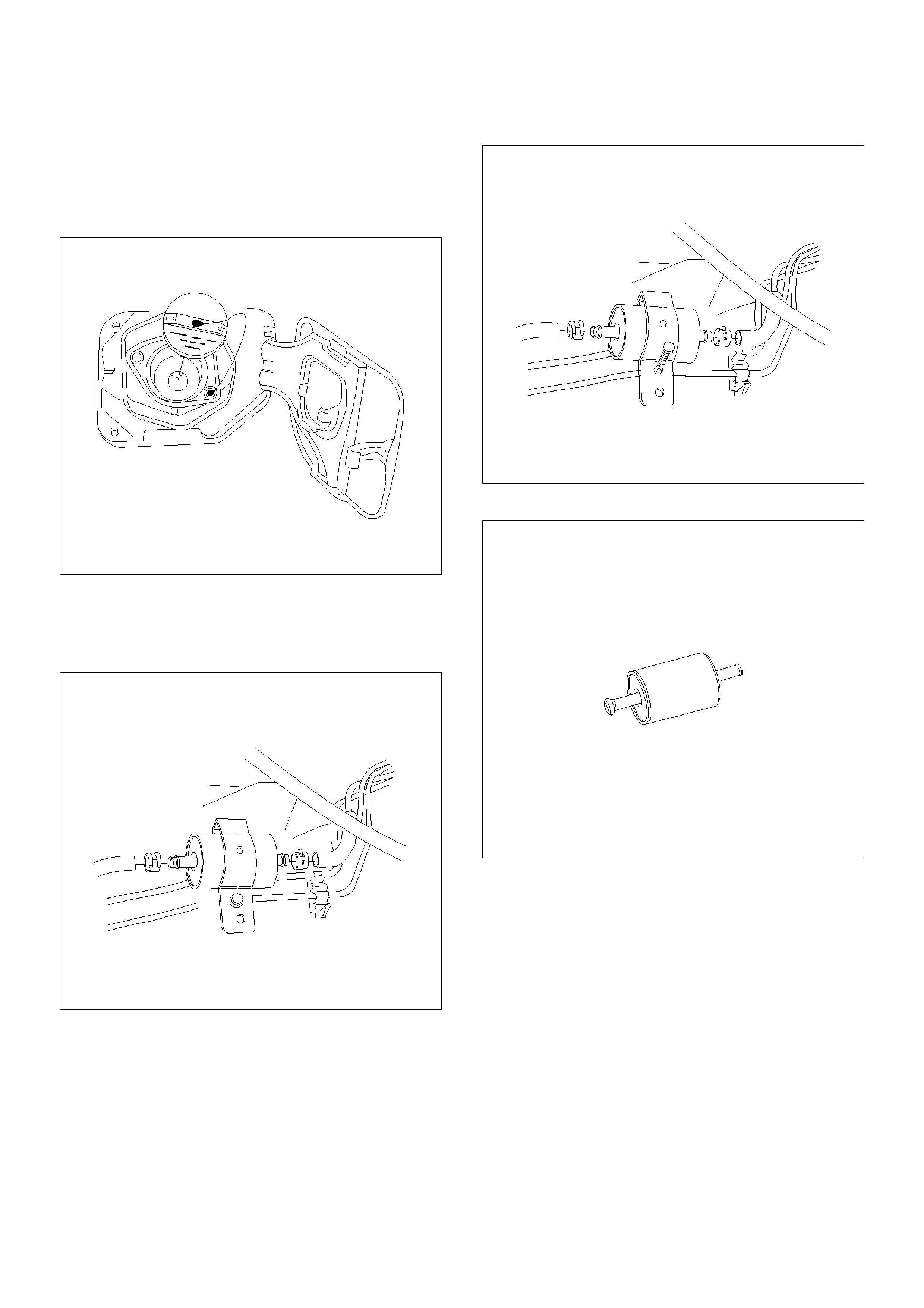
Fuel Filter
Removal Procedure
1. Disconnect the negative battery cable.
2. Remove the fuel filler cap.
041RW005
3. Disconnect the fuel line from the fuel filter on the
engine side.
4. Disconnect the fuel line from the fuel filter on the
fuel tank side.
041RW006
5. Remove the bolt on the fuel filter holder.
041RW007
6. Remove the fuel filter.
041RW008
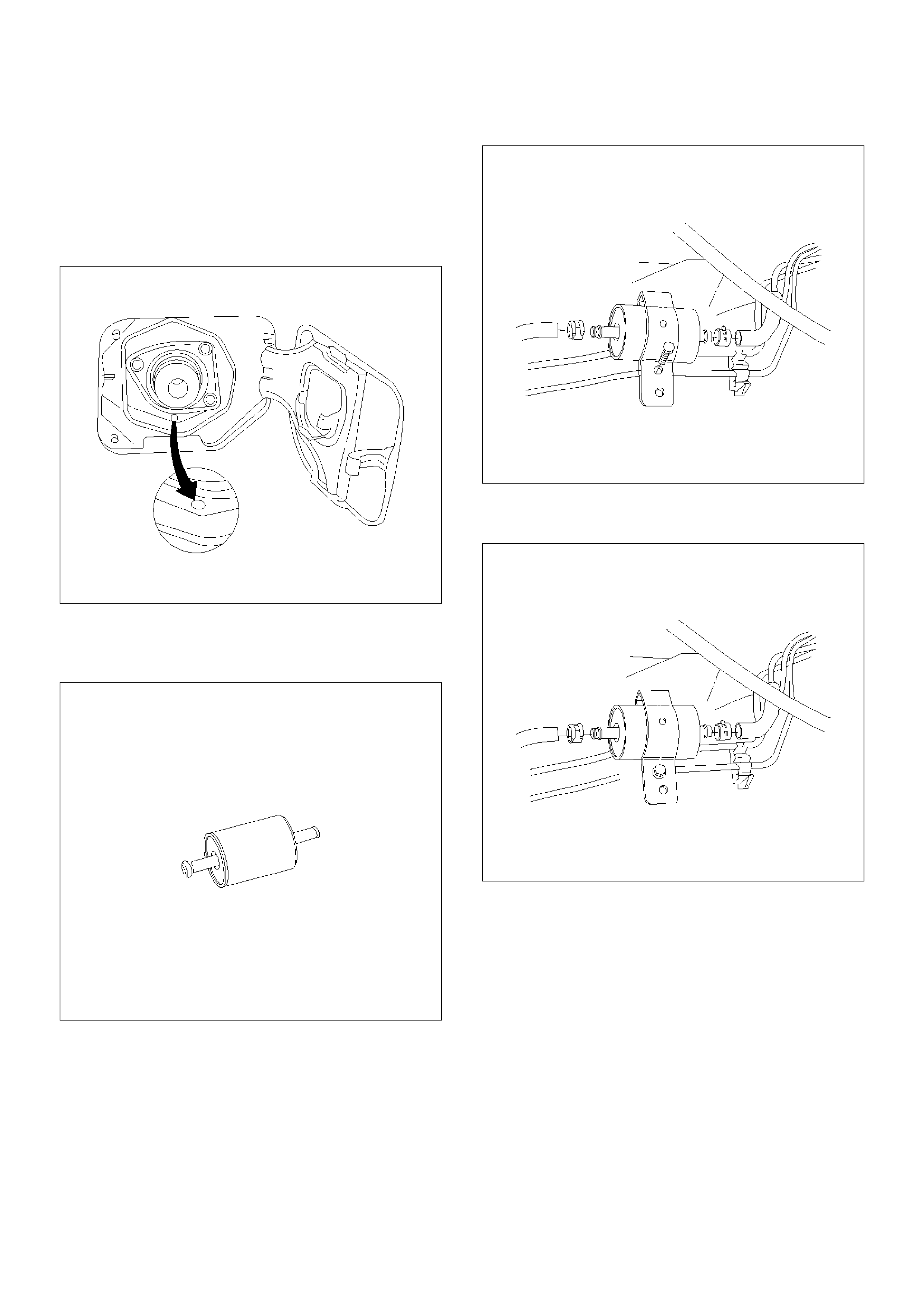
Inspection Procedure
1. Replace the fuel filter when the following occur:
• Fuel leaks from the fuel filter body.
• The fuel filter body is damaged.
• The fuel filter is clogged with dirt or sediment.
2. If the drain hole is clogged, clean the drain.
041RW009
Installation Procedure
1. Install the fuel filter in the correct direction.
041RW008
2. Install the bolt on the fuel filter holder.
041RW007
3. Connect the fuel line on the engine side.
4. Connect the fuel line on the fuel tank side.
041RW006
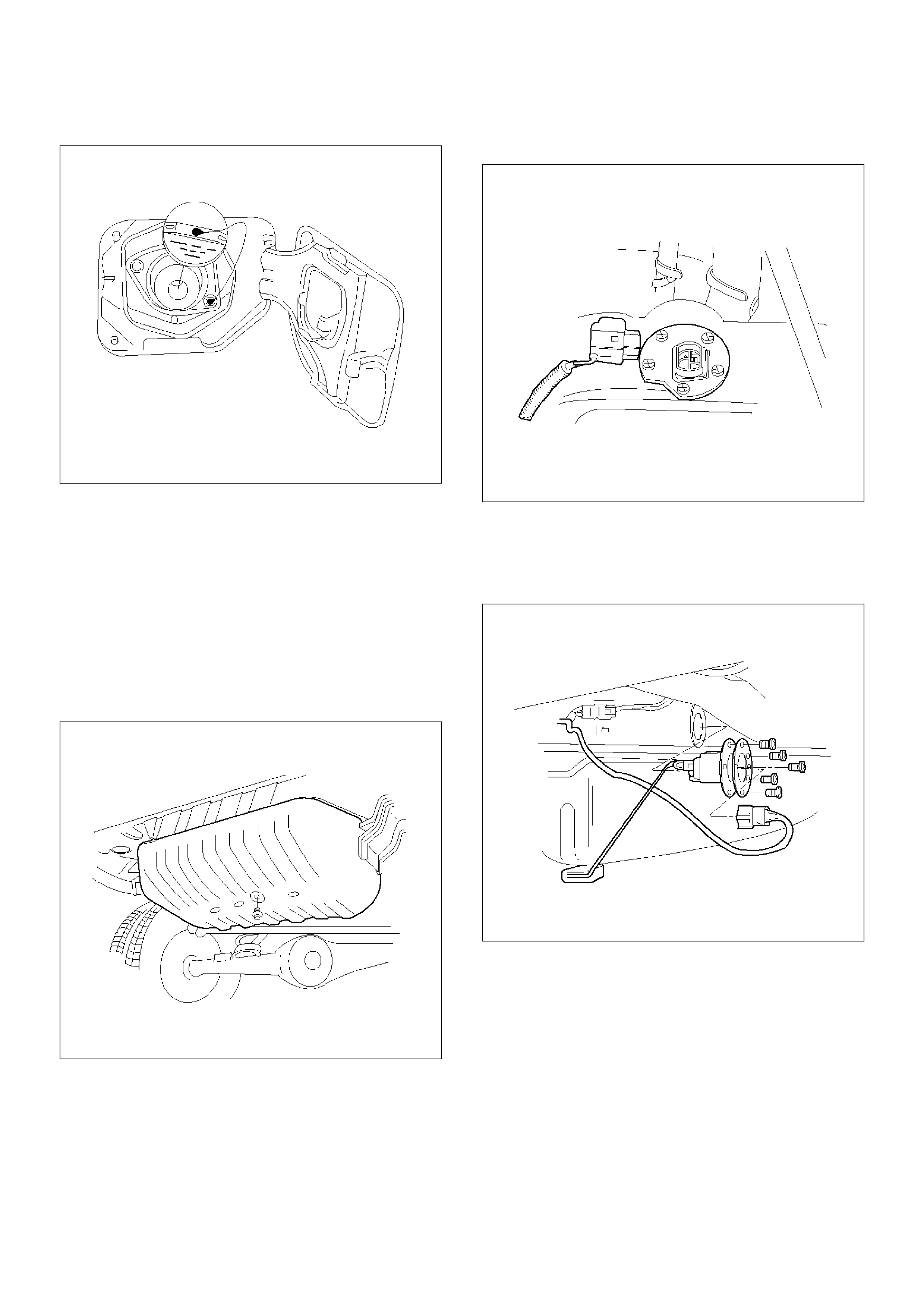
5. Install the fuel filler cap.
041RW005
6. Connect the negative battery cable.
Fuel Gauge Unit
Removal Procedure
1. Disconnect the negative battery cable.
2. Loosen the fuel filler cap.
3. Drain the fuel from the tank.
Tighten
• Tighten the drain plug to 20 N·m (14 lb ft.).
TS22907
4. Disconnect the wiring connector from the fuel gauge
unit.
TS23771
5. Remove the fuel gauge unit retaining screws.
6. Remove the fuel gauge unit.
• Cover or plug the fuel tank to prevent dust, dirt, or
debris from entering the tank.
TS22911
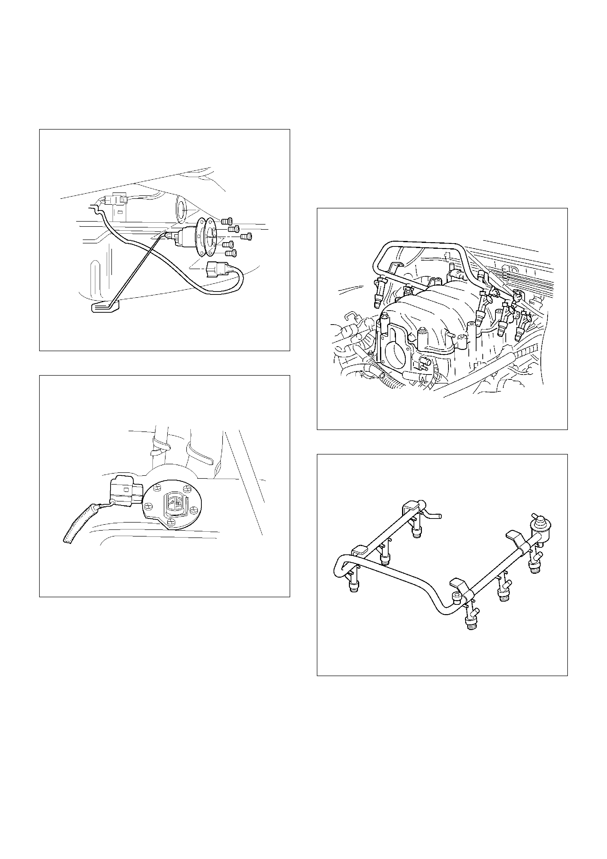
Installation Procedure
1.Install the fuel gauge unit.
2.Install the fuel gauge unit retaining screws.
TS22911
3.Connect the wiring connector to the fuel gauge unit.
TS23771
4.Fill the fuel tank with fuel.
•Tighten the fuel filler cap.
•Check for leaks at the fuel gauge unit gasket.
5.Connect the negative battery cable.
Fuel Injectors
Removal Procedure
NOTE: If the fuel injectors are leaking, the engine oil
may be contaminated with fuel. Check the oil for signs
of contamination and change the oil and the filter if
necessary.
NOTE: Use care in removing the fuel injectors in order
to prevent damage to the fuel injector electrical
connector pins or the fuel injector nozzles. The fuel
injector is an electrical component and should not be
immersed in any type of cleaner as this may damage
the fuel injector.
Important: Fuel injectors are serviced as a complete
assembly only.
1.Disconnect the negative battery cable.
2.Remove the upper intake manifold. Refer to
Common Chamber in Engine Mechanical..
3.Remove the fuel rail. Refer to Fuel Rail.
014RW164
4. Remove the injector retainer clip.
055RW009
5. Remove the fuel injector assembly.
6. Remove the O-ring from the fuel injector.
7. Remove the O-ring backup from the fuel injector .
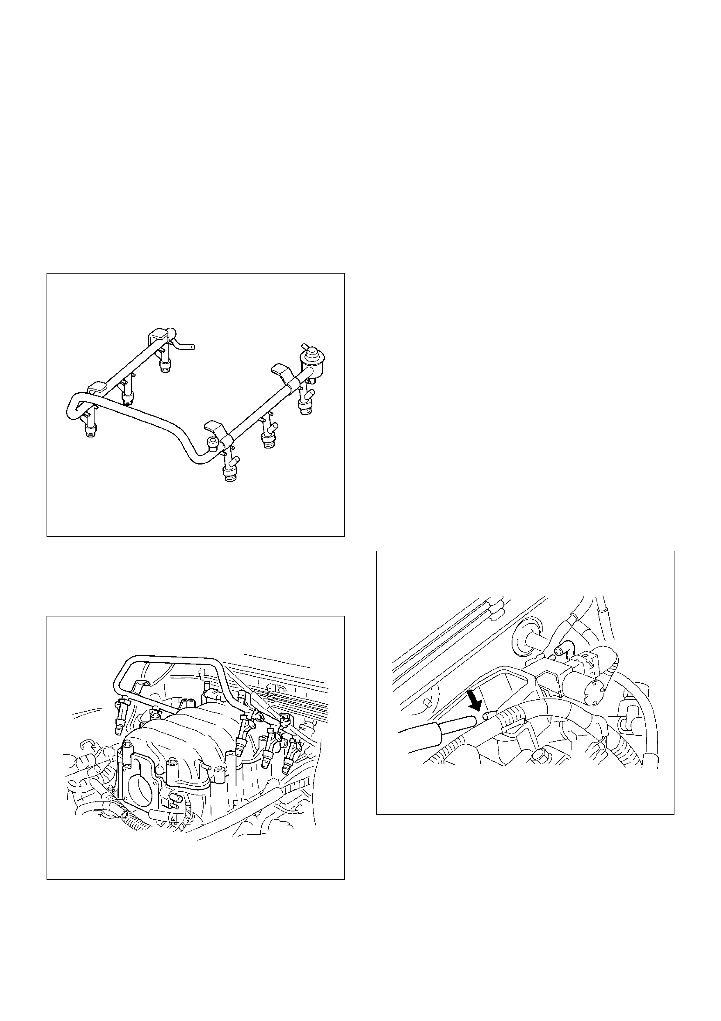
Inspection Procedure
1.Inspect the O-rings for cracks or leaks.
2.Replace worn or damaged O-rings.
3.Lubricate the new O-rings with engine oil before
installation.
Installation Procedure
1.Install the O-ring backup on the fuel injector.
2.Install the new O-ring on the fuel injector.
3.Install the fuel injector on the fuel rail.
055RW009
4.Use new fuel injector retainer clips to retain the fuel
injector to the fuel rail.
5.Coat the end of the fuel injector with engine oil.
6.Install the fuel rail. Refer to Fuel Rail.
014RW164
7.Install the upper intake manifold. Refer to Common
Chamber in Engine Mechanical.
8.Install the engine cover.
9.Connect the negative battery cable.
Fuel Pressure Regulator
Removal Procedure
CAUTION: To reduce the risk of fire and personal
injury, it is necessary to relieve the fuel system
pressure before servicing the fuel system
components.
CAUTION: After relieving the system pressure, a
small amount of fuel may be released when
servicing fuel lines or connections. Reduce the
chance of personal injury by covering the fuel line
fittings with a shop towel before disconnecting the
fittings. The towels will absorb any fuel that may
leak out. When the disconnect is completed, place
the towel in an approved container.
NOTE: Compressed air must never be used to test or
clean a fuel pressure regulator, as damage to the fuel
pressure regulator may result.
NOTE: To prevent damage to the fuel pressure
regulator, do not immerse the pressure regulator in
solvent.
1.Depressurize the fuel system. Refer to Fuel
Pressure Relief Procedure.
2.Disconnect the negative battery cable.
3.Remove the fuel pump relay. Refer to Fuel Pump
Relay.
4. Remove the pressure regulator hose from the fuel
pressure regulator.
014RW110
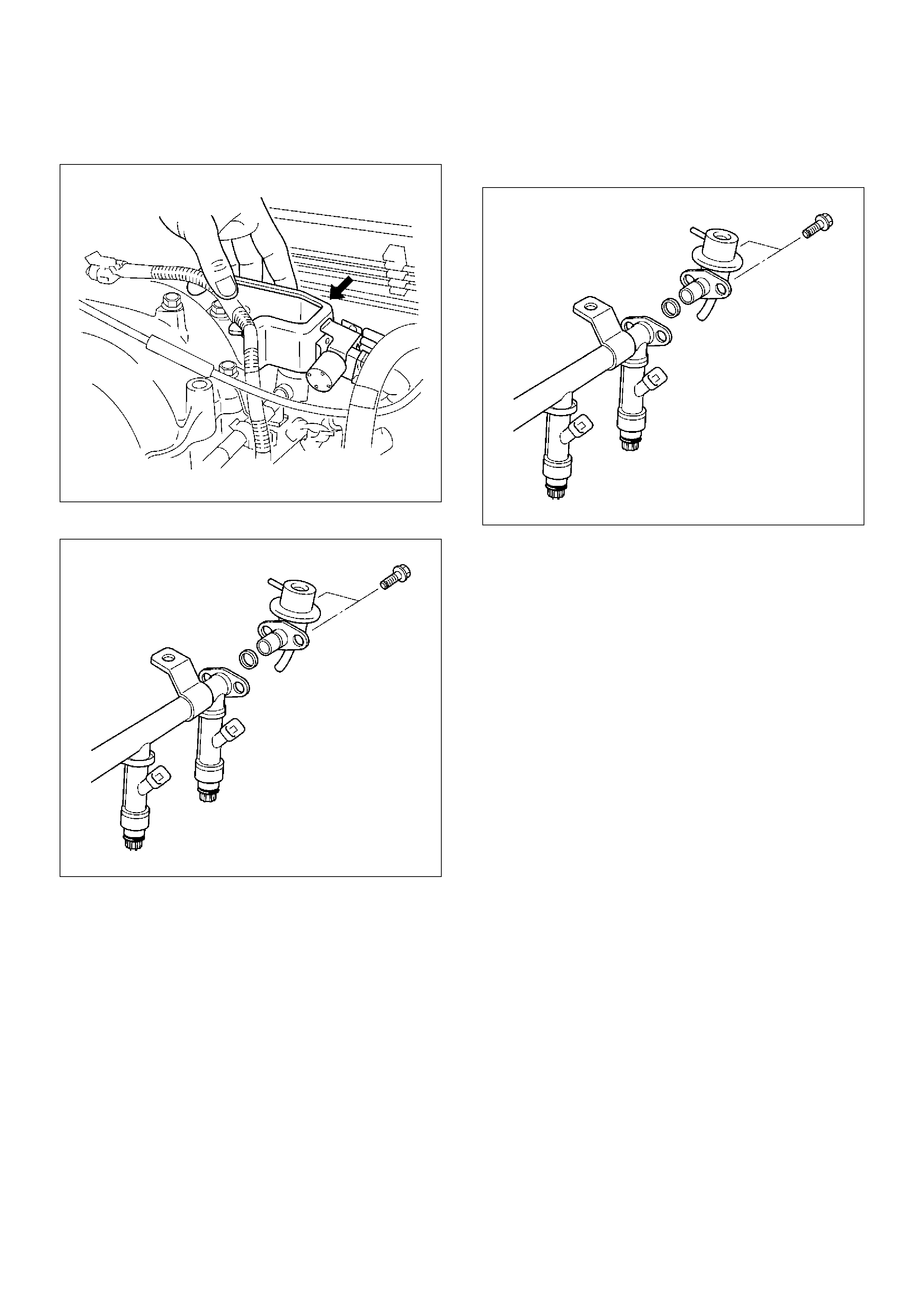
5. Remove the two bolts from the protector that
secures the common chamber.
014RW109
6. Remove the fuel pressure regulator attaching screw.
F06RW043
7. Remove the fuel pressure regulator from the fuel
rail.
Disassembly Procedure
1. Remove the O-ring from the fuel pressure regulator.
2. Loosen the swivel nut.
3. Remove the fuel return line from the fuel pressure
regulator.
4. Remove the O-ring from the fuel return line.
• The O-ring may be left inside the fuel pressure
regulator instead of on the fuel return line.
F06RW043
Assembly Procedure
1. Install a new O-ring on the fuel return line.
2. Install the fuel return line on the fuel pressure
regulator.
NOTE: Do not over-tighten the swivel nut on the fuel
pressure regulator. The fuel pressure regulator can be
damaged and fuel may leak if the swivel nut is
over-tightened.
3. Tighten the swivel nut.
4. Install a new O-ring on the fuel pressure regulator.

Installation Procedure
1.Install the fuel pressure regulator attaching screw.
Tighten
•Tighten the fuel pressure regulator attaching screw
to 3 N·m (26 lb in.).
F06RW043
2.Install the fuel pressure regulator on the fuel rail.
3.Install the two bolts to the protector that secures the
common chamber.
014RW109
4.Install the pressure regulator hose to the fuel
pressure regulator.
014RW110
5.Install the fuel pump relay. Refer to Fuel Pump
Relay.
6. Connect the negative battery cable.
7. Crank the engine until it starts. Cranking the engine
may take longer than usual due to trapped air in the
fuel lines.
Fuel Metering System
Fuel Pressure Relief Procedure
CAUTION: To reduce the risk of fire and personal
injury, it is necessary to relieve the fuel system
pressure before servicing the fuel system
components.
CAUTION: After relieving the system pressure, a
small amount of fuel may be released when
servicing fuel lines or connections. Reduce the
chance of personal injury by covering the fuel line
fittings with a shop towel before you disconnect the
fittings. The towels will absorb any fuel that may
leak out. When the disconnect is completed, place
the towel in an approved container.
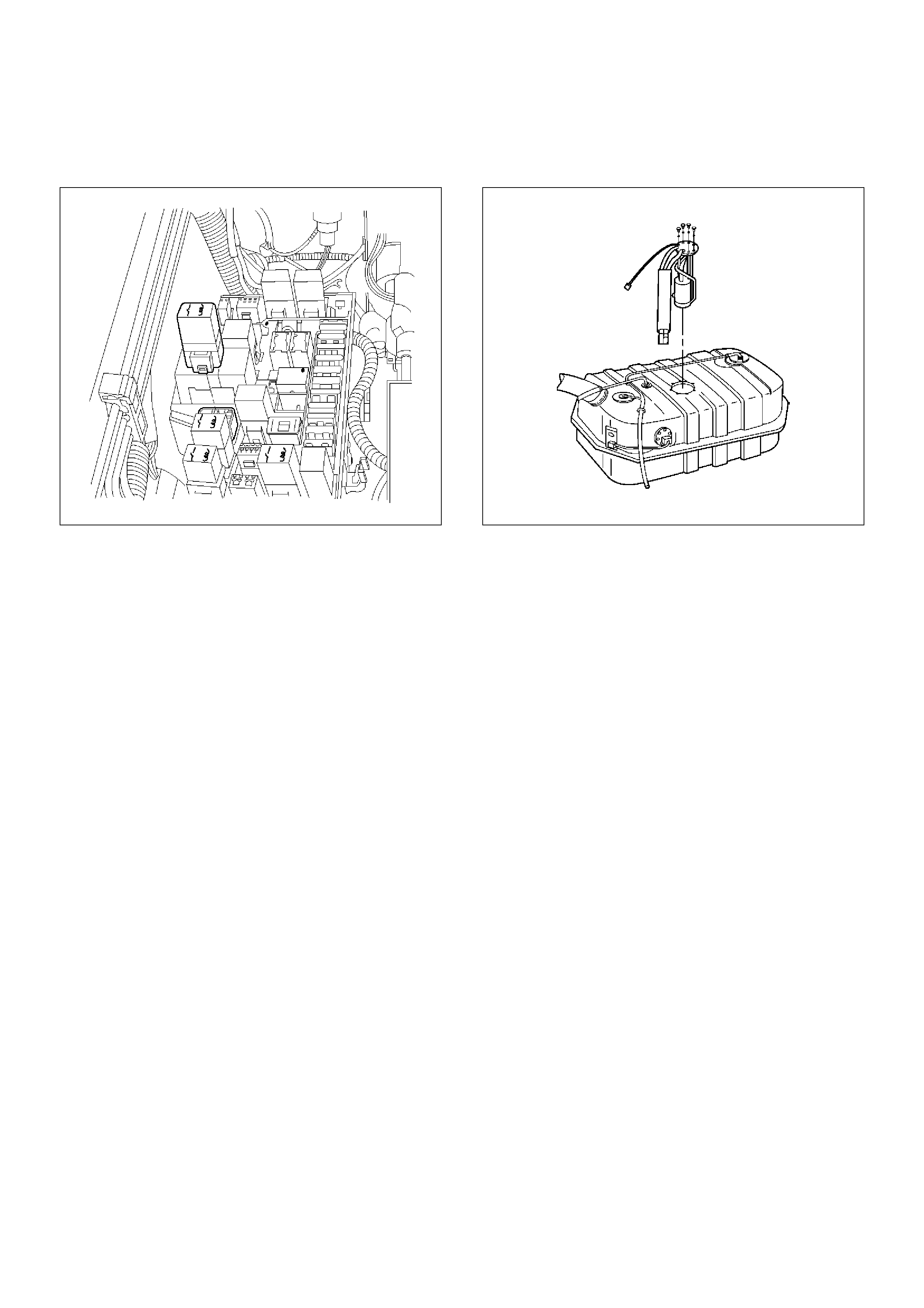
1.Remove the fuel cap.
2.Remove the fuel pump relay from the underhood
relay box. Refer to Fuel Pump Relay.
TS23976R
3.Start the engine and allow it to stall.
4.Crank the engine for 30 seconds.
5.Disconnect the negative battery cable.
Fuel Pump Assembly
Removal Procedure
1.Disconnect the negative battery cable.
2.Drain all the fuel from the tank.
3.Install and tighten the drain plug.
Tighten
•Tighten the drain plug to 20 N·m (14 lb ft.).
4.Remove the fuel tank. Refer to Fuel Tank.
5.Remove the retaining screws from the fuel tank.
6.Remove the fuel pump assembly from the fuel tank.
•Cover the fuel pump opening in order to prevent
dust, dirt, or debris from entering the fuel tank.
TS23795
Inspection Procedure
1.Inspect the fuel pump gasket for tears, cracks,
stretching, or rotting. If any of these conditions are
found, replace the fuel pump gasket.
2.Inspect the in-tank fuel filter for tears or evidence of
dirt, debris, or water in the fuel. If any of these
conditions are found, replace the in-tank fuel filter.
Installation Procedure
1.Install the fuel pump assembly.
2.Install the fuel pump assembly retaining screws.
3.Install the fuel tank assembly. Refer to Fuel Tank.
4. Fill the tank with fuel.
5. Tighten the fuel filler cap.
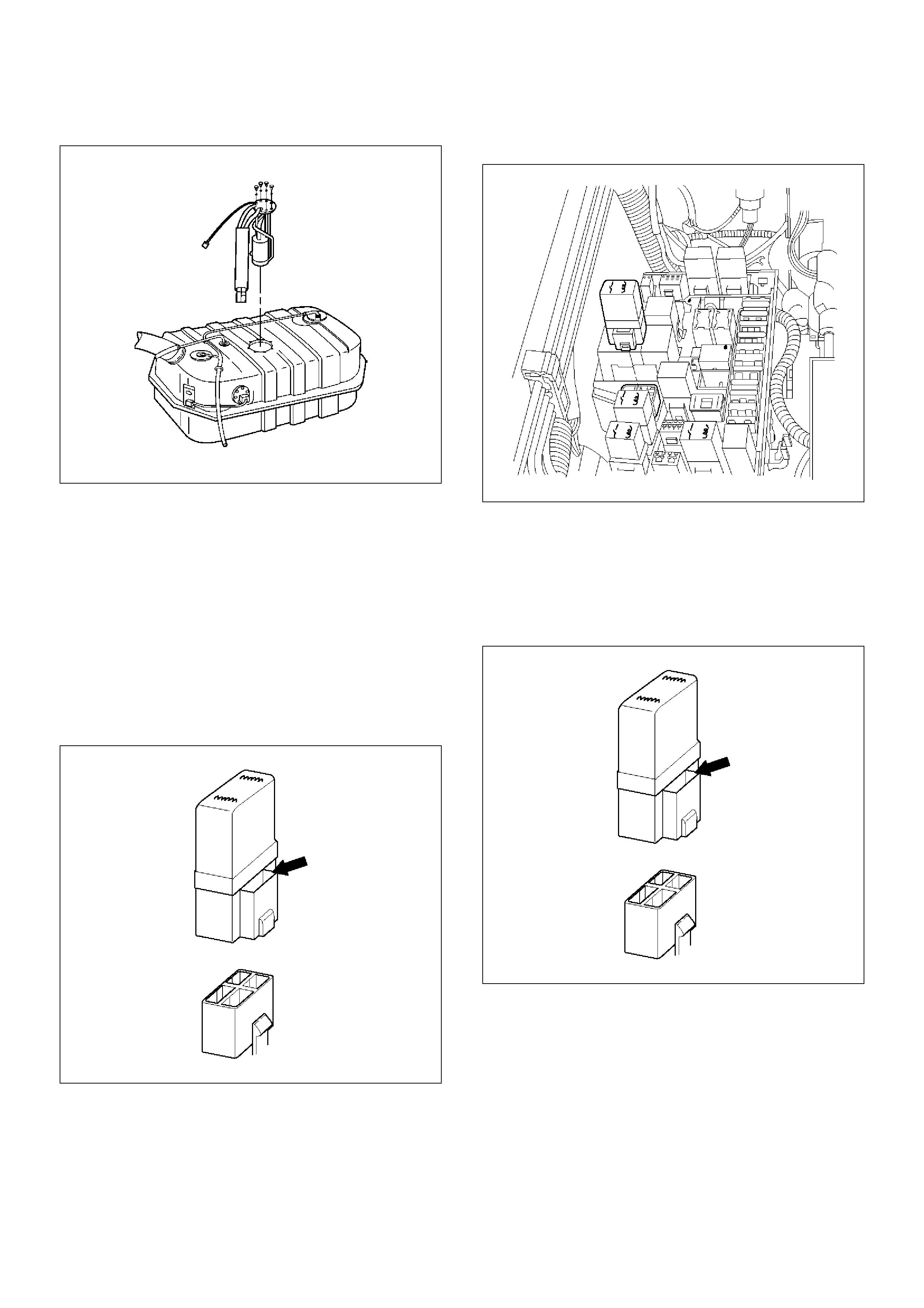
6. Connect the negative battery cable.
TS23795
Fuel Pump Relay
Removal Procedure
1. Remove the fuse and relay box cover from under
the hood.
2. Consult the diagram on the cover to determine
which is the correct relay.
3. Insert a small screwdriver into the catch slot on the
forward side of the fuel pump relay.
• The screwdriver blade will release the catch
inside.
T321092
4. Pull the relay straight up and out of the fuse and
relay box.
TS23976R
Installation Procedure
1. Insert the relay into the correct place in the fuse and
relay box with the catch slot facing forward.
2. Press down until the catch engages.
• An audible “click” will be heard.
T321092
3. Install the fuse and relay box cover.
Fuel Rail Assembly
Removal Procedure
NOTE:
• Do not attempt to remove the fuel inlet fitting on the
fuel rail. It is staked in place. Removing the fuel inlet
fitting will result in damage to the fuel rail or the
internal O-ring seal.
• Use care when removing the fuel rail assembly in
order to prevent damage to the injector electrical
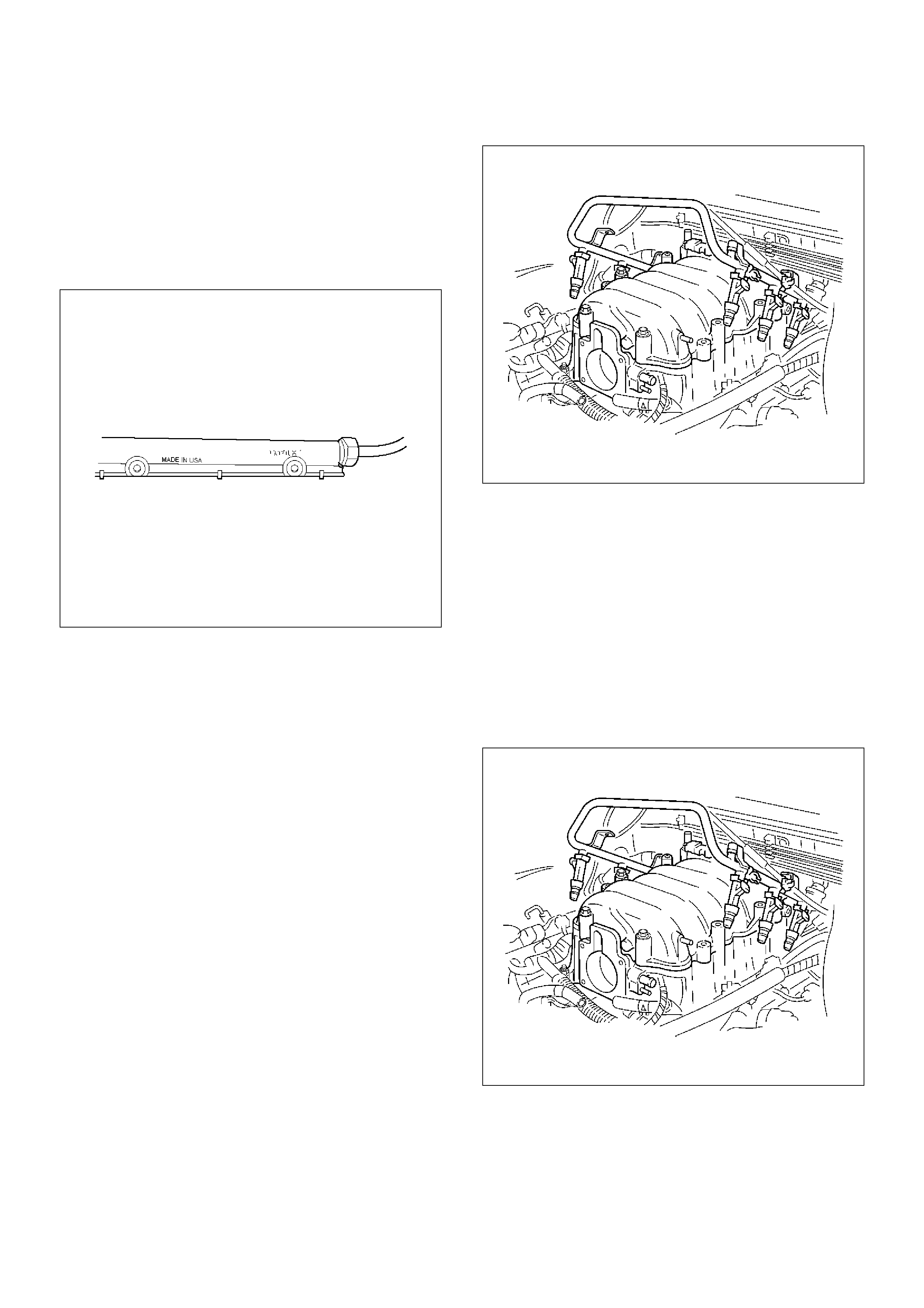
connector terminals and the injector spray tips.
•Fittings should be capped and holes plugged during
servicing to prevent dirt and other contaminants from
entering open lines and passages.
Important: An eight-digit identification number is
stamped on the side of the fuel rail. Refer to this
number when you service the fuel rail or when a
replacement part is required.
TS24022
Before removal, the fuel rail assembly may be cleaned
with a spray type engine cleaner. Follow the spray
package instructions. Do not immerse the fuel rails in
liquid cleaning solvent.
1.Depressurize the fuel system. Refer to Fuel
Pressure Relief Procedure in this Section.
2.Disconnect the negative battery cable.
3.Remove the engine cover.
4.Disconnect the accelerator pedal cable from throttle
body and cable bracket.
5.Disconnect the connectors from manifold absolute
pressure sensor, solenoid valve, electric vacuum
sensing valve.
6.Disconnect the vacuum hose on canister VSV and
positive crankcase ventilation hose.
7.Remove the common chamber. Refer to the
common chamber in Engine Mechanical.
1.Lift up carefully on the fuel injectors. Do not
separate the fuel injectors from the fuel rail.
2.If an injector becomes separated from the fuel
rail, the infector O-ring seals and the retainer
clip must be replaced.
3.Drain residual fuel into an approved container.
014RW164
8.If removal of the fuel pressure regulator is
necessary, refer to Fuel Pressure Regulator.
9.If removal of the fuel injectors is necessary, refer to
Fuel Injectors.
Installation Procedure
1.If the fuel injectors were removed, install them.
Refer to Fuel Injectors.
2.If the fuel pressure regulator was removed, install it.
Refer to Fuel Pressure Regulator.
3.Install the common chamber. Refer to common
chamber in engine Mechanical.
014RW164
4. Connect the vacuum hose on Canister VSV and
positive crankcase ventilation hose.
5. Connect the connectors to manifold absolute
pressure sensor, solenoid valve, electric vacuum
sensing valve.
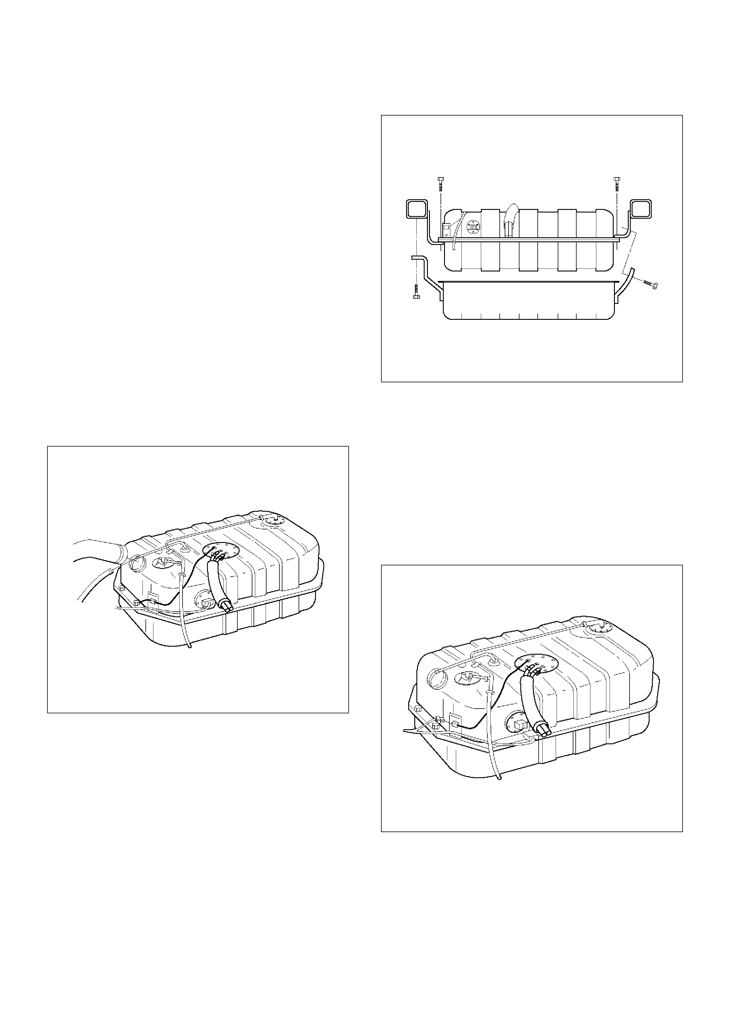
6. Connect the accelerator pedal cable to throttle body
and cable bracket.
7. Install the engine cover.
8. Connect the negative battery cable.
9. Crank the engine until it starts. Cranking the engine
may take longer than usual due to trapped air in the
fuel rail and in the injectors.
Fuel Tank
Removal Procedure
1. Disconnect the negative battery cable.
2. Loosen the fuel filler cap.
3. Drain the fuel from the tank into an approved
container.
4. Install and tighten the drain plug.
Tighten
• Tighten the drain plug to 20 N·m (14 lb ft.).
5. Disconnect the fuel filler hose at the fuel tank.
6. Disconnect the air breather hose at the fuel tank.
TS23796
7. Remove the undercover retaining bolts.
8. Remove the undercover.
TS23797
9. Disconnect the wiring connector to the fuel pump.
10. Disconnect the wiring connector to the fuel gauge
unit.
11. Remove the fuel gauge unit connector from the
bracket.
12. Disconnect the EVAP vapor hose.
13. Disconnect the fuel supply hose.
14. Disconnect the fuel return hose.
• Plug the hoses to prevent dust from entering the
hoses.
TS23769
15. Remove the fuel tank retaining bolts on both sides.
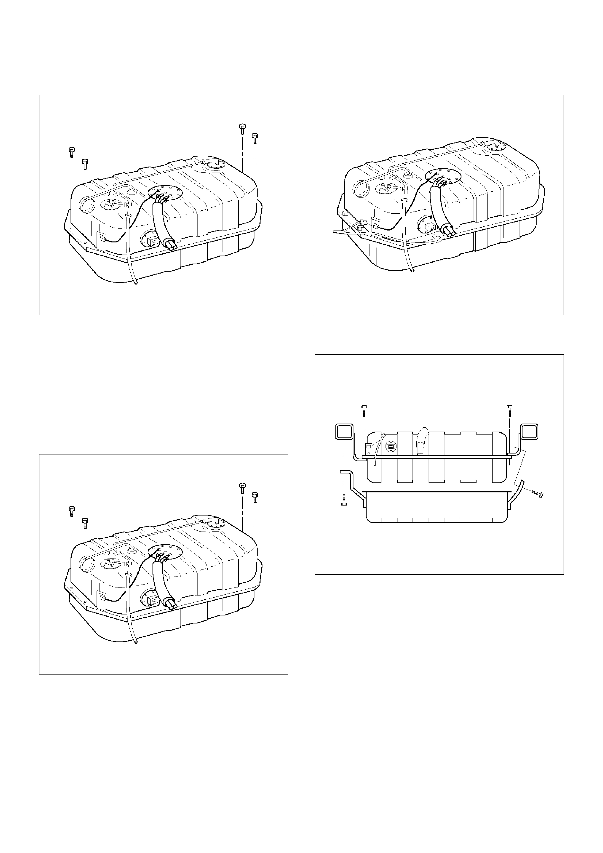
16. Remove the fuel tank.
TS23770
Installation Procedure
1. Install the fuel tank.
• Place the flanges on the left and right side of the
tank on the bracket.
2. Install the fuel tank retaining bolts.
Tighten
• Tighten the fuel tank retaining bolts to 36 N·m (27
lb ft.).
TS23770
3. Connect the fuel return hose.
4. Connect the fuel supply hose.
5. Connect the EVAP vapor hose.
6. Connect the wiring connector for the fuel gauge unit.
7. Connect the fuel gauge wiring connector to the
bracket.
8. Connect the wiring connector for the fuel pump.
TS23769
9. Install the undercover.
10. Secure the undercover with the retaining bolts.
TS23797
11. Connect the fuel filler fuse at the tank.
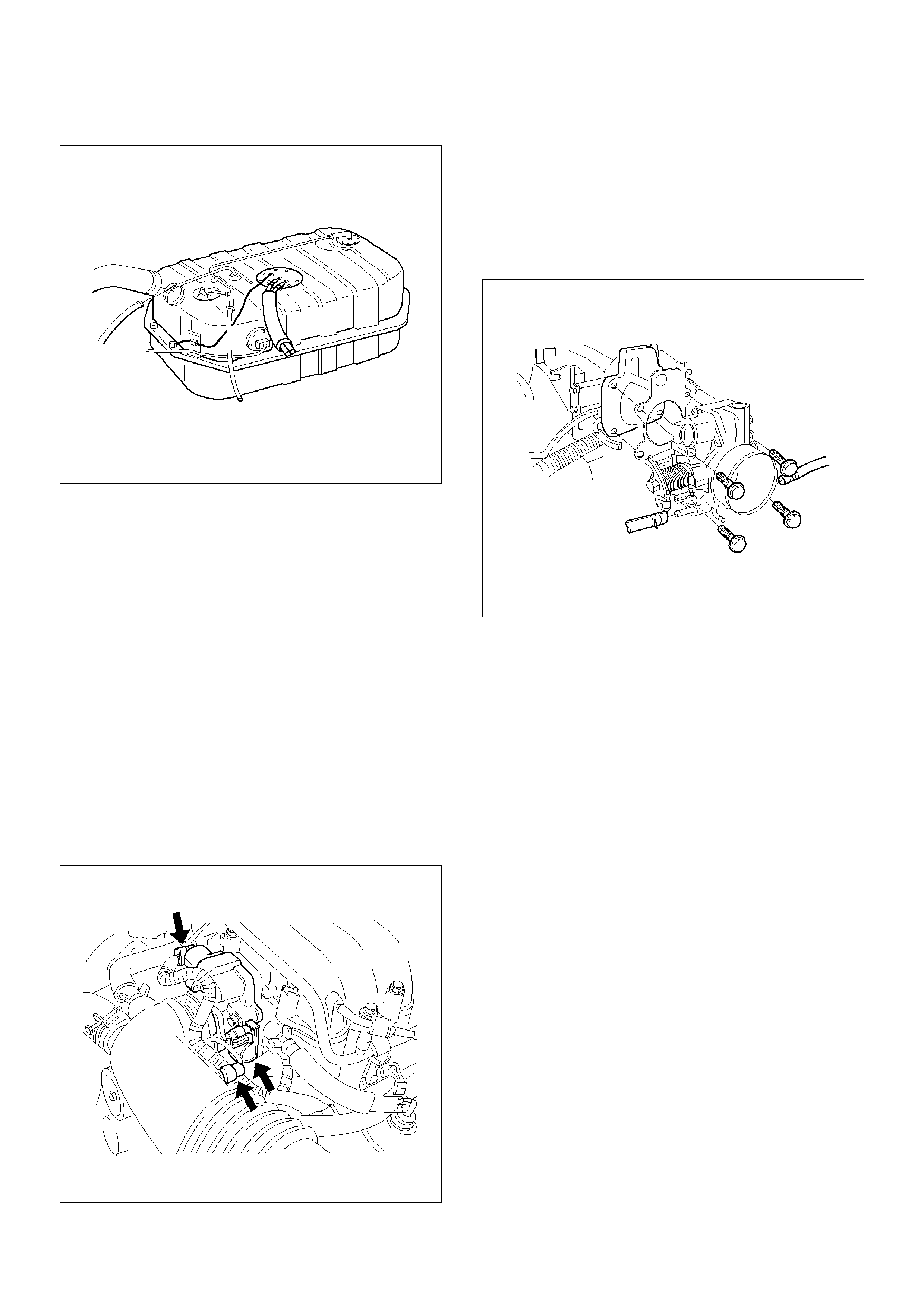
12.Connect the air breather hose at the tank.
TS23796
13.Fill the fuel tank with fuel.
14.Tighten the fuel filler cap.
15.Connect the negative battery cable.
Throttle Body (TB)
Removal Procedure
1.Disconnect the negative battery cable.
2.Drain the cooling system. Refer to Cooling System.
3.Remove the accelerator cable assembly. Refer to
Accelerator Cable in Engine Speed Control
System..
4.Disconnect the electrical connectors:
•Throttle position (TP) sensor.
•Idle air control (IAC) solenoid.
•Intake air temperature (IAT) sensor. Refer to
Intake Air Temperature Sensor.
035RW023
5.Disconnect the vacuum hose below the air horn.
6.Remove the intake air duct clamp.
7.Disconnect the intake air duct.
8.Disconnect the coolant lines from the throttle body.
9.Remove the bolts from the common chamber.
10.Remove the throttle body from the common
chamber.
11.Remove the gasket from the upper intake manifold.
035RW024
12.Remove the IAC. Refer to Idle Air Control (IAC)
Solenoid.
13.Remove the TP sensor. Refer to Throttle Position
(TP) Sensor.
Inspection Procedure
NOTE: Do not use solvent of any type when you clean
the gasket surfaces on the intake manifold and the
throttle body assembly. The gasket surfaces and the
throttle body assembly may be damaged as a result.
•If the throttle body gasket needs to be replaced,
remove any gasket material that may be stuck to the
mating surfaces of the manifold.
•Do not leave any scratches in the aluminum casting.
Installation Procedure
1.Install the TP sensor. Refer to Throttle Position (TP)
Sensor.
2.Install the IAC. Refer to Idle Air Control (IAC)
Solenoid.
3. Install the gasket on the common chamber.
4. Install the throttle body on the common chamber.
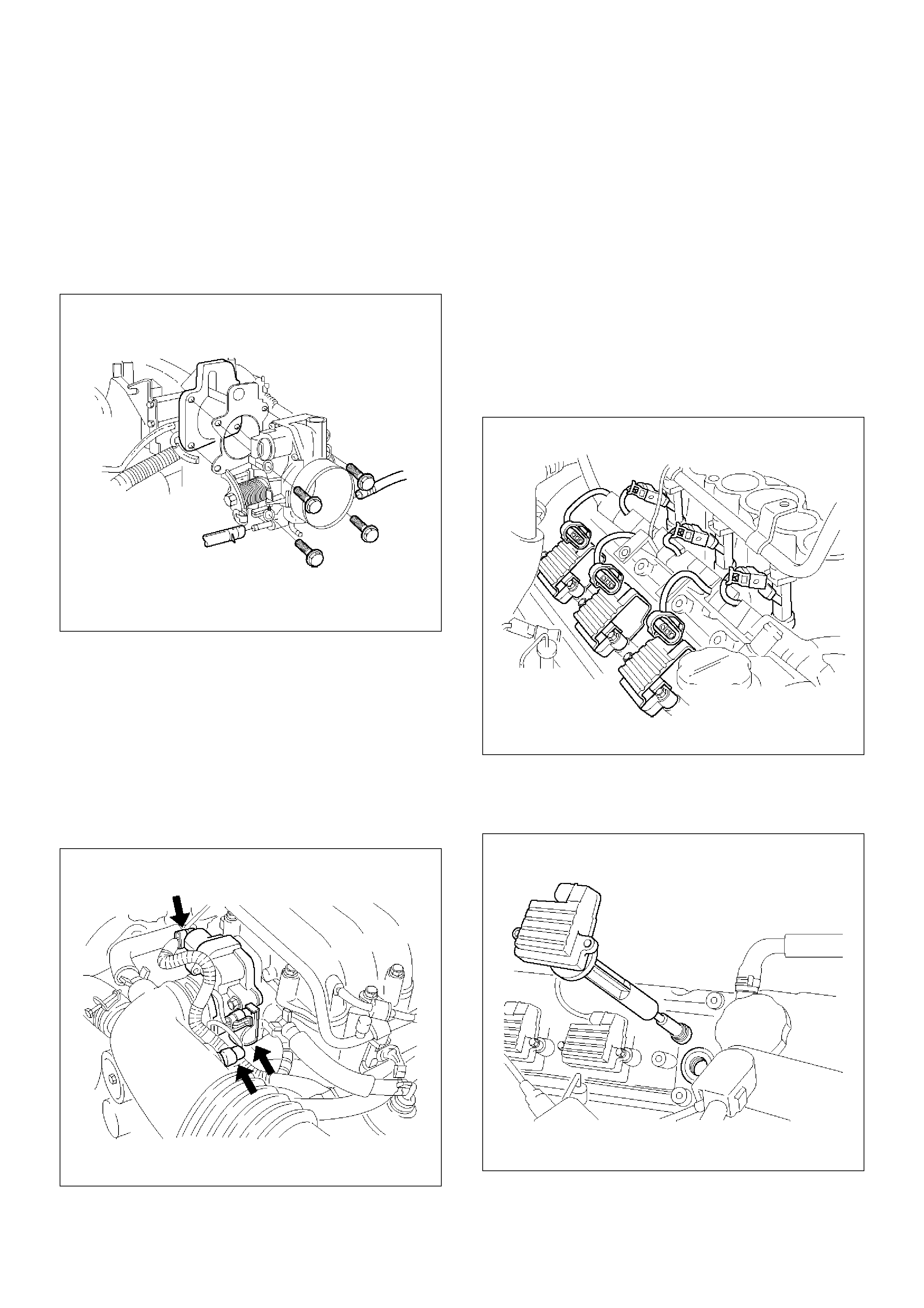
5.Secure the gasket and the throttle body with the four
bolts.
•The vacuum lines must be properly routed under
the throttle body before tightening the mounting
bolts.
Tighten
•Tighten the throttle body mounting bolts to 24 N·m
(17 lb ft.).
035RW024
6.Install the coolant lines.
7.Connect all the vacuum lines.
8.Install the intake air duct.
9.Tighten the intake air duct clamp.
10.Connect all the electrical connectors:
•Throttle position (TP) sensor.
•Idle air control (IAC) solenoid.
•Intake air temperature (IAT) sensor. Refer to
Intake Air Temperature Sensor.
035RW023
11.Install the accelerator cable assembly. Refer to
Accelerator Cable in Engine Speed Control
System..
12.Fill the cooling system. Refer to Cooling System.
13. Install the negative battery cable.
Electronic Ignition System
Removal Procedure
1. Disconnect the negative battery cable.
2. Disconnect the electrical connector at the ignition
coil.
3. Remove the two screws that secure the ignition coil
to the rocker cover.
014RW108
4. Remove the ignition coil and the spark plug boot
from the spark plug.
• Twist the ignition coil while pulling it straight up.
014RW091
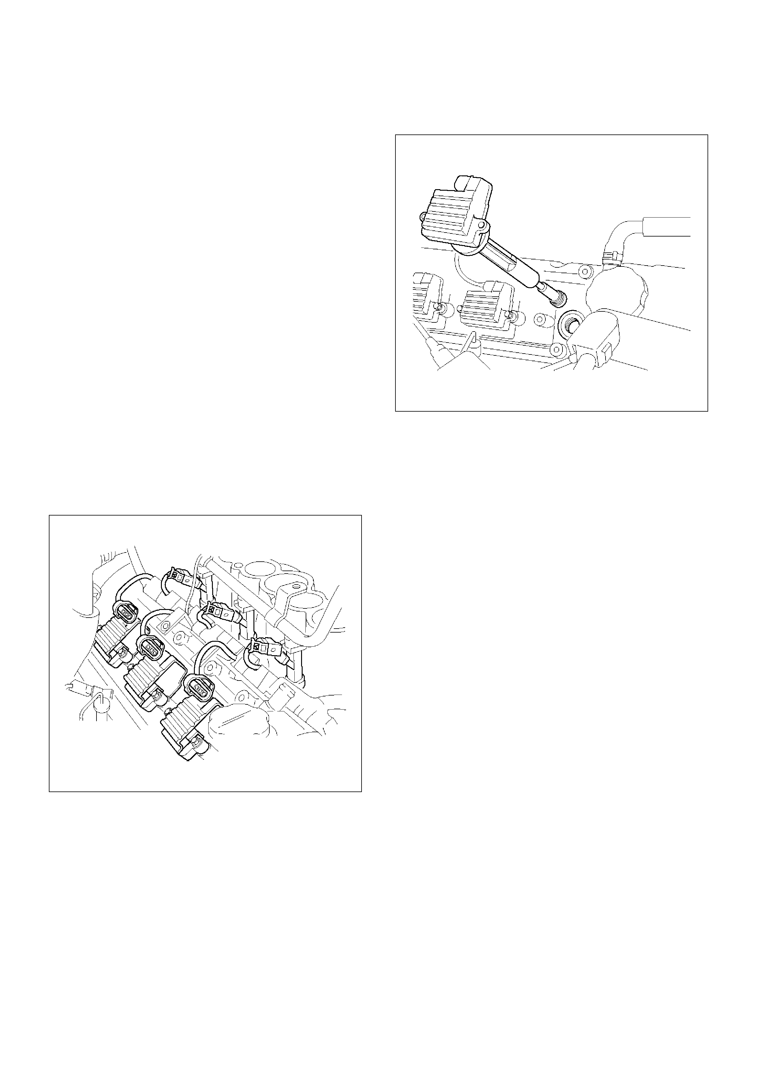
5.Use the spark plug socket in order to remove the
spark plug from the engine.
Spark Plug Gap Check
•Check the gap of all spark plugs before installation.
•Use a round wire feeler gauge to ensure an accurate
check.
•Plugs installed with the wrong gap can cause poor
engine performance and excessive emissions.
Installation Procedure
NOTE: The plug must thread smoothly into the cylinder
head and be fully seated. Use a thread chaser if
necessary to clean the threads in the cylinder head.
Cross-threading or failure to fully seat the spark plug
can cause plug overheating, exhaust blow-by gas, or
thread damage. Do not overtighten the spark plugs.
Over tightening can cause aluminum threads to strip.
1.Install the spark plug in the engine. Use the
appropriate spark plug socket.
Tighten
•Tighten the spark plug to 18 N·m (13 lb ft.).
2.Install the ignition coil and spark plug boot over the
spark plug.
014RW108
3.Secure the ignition coil to the rocker cover with two
screws.
014RW091
4.Connect the electrical connector at the ignition coil.
5.Connect the negative battery cable.
Catalytic Converter
Removal and Installation Procedure
Refer to Engine Exhaust in Engine.
Air Conditioning Relay
Removal Procedure
1. Remove the fuse and relay box cover from under
the hood.
2. Consult the diagram on the cover to determine
which is the correct relay.
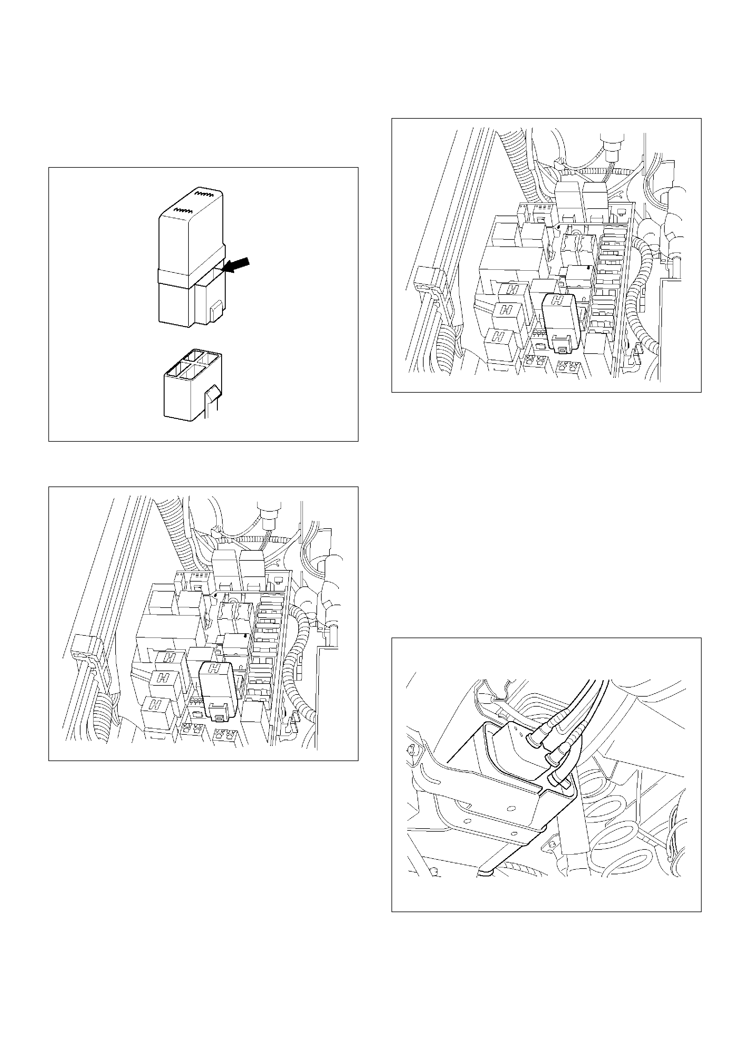
3.Insert a small screwdriver into the catch slot on the
forward side of the fuel pump relay.
•The screwdriver blade will release the catch
inside.
T321092
4.Pull the relay straight up and out of the fuse and
relay box.
TS23986
Installation Procedure
1.Insert the relay into the correct place in the fuse and
relay box with the catch slot facing forward.
2.Press down until the catch engages.
•An audible “click” will be heard.
3.Install the fuse and relay box cover.
TS23986
EVAP Canister Hoses
Service Information
To view the routing of the EVAP canister hoses, refer to
Vehicle Emission Control Information in Diagnosis.
Use 6148M or equivalent when you replace the EVAP
canister hoses.
EVAP Canister
Removal Procedure
1. Disconnect the negative battery cable.
2. Disconnect the three hoses from the EVAP canister.
014RW145
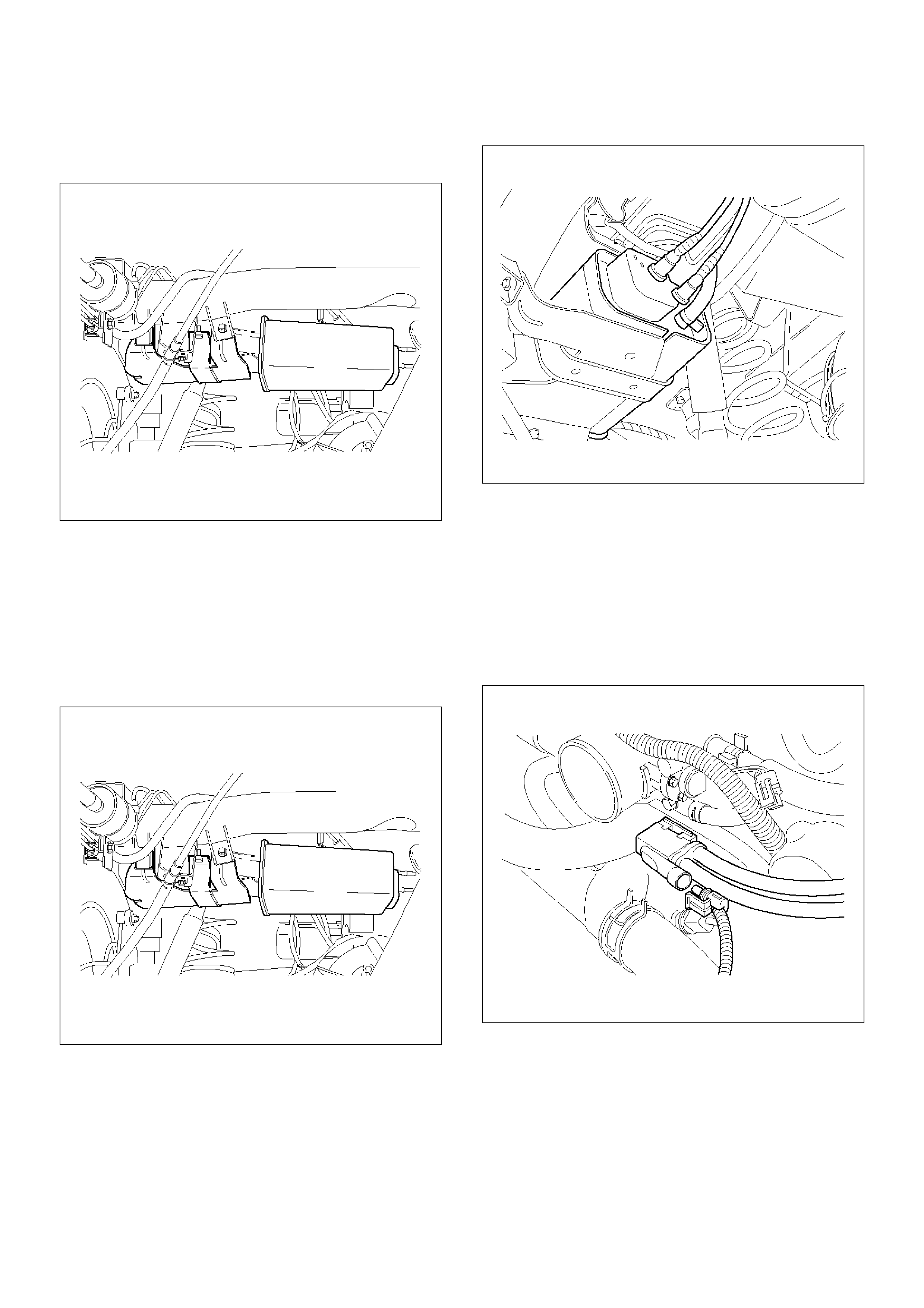
3. Remove the retaining two bolts on the mounting
bracket and slide the canister out of mounting
bracket.
014RW146
Inspection Procedure
1. Inspect the hoses for cracks and leaks.
2. Inspect the canister for a damaged case.
Installation Procedure
1. Slide the canister into mounting bracket and install
the mounting bracket two bolts.
014RW146
2. Connect the three hoses to the EVAP canister.
014RW145
3. Disconnect the negative battery cable.
EVAP Canister Purge Solenoid
Removal Procedure
1. Disconnect the electrical connector from the EVAP
canister purge solenoid.
2. Disconnect the vacuum hoses from the EVAP
canister purge solenoid.
014RW136
3. Remove the EVAP canister purge solenoid retaining
bolt from the upper intake manifold.
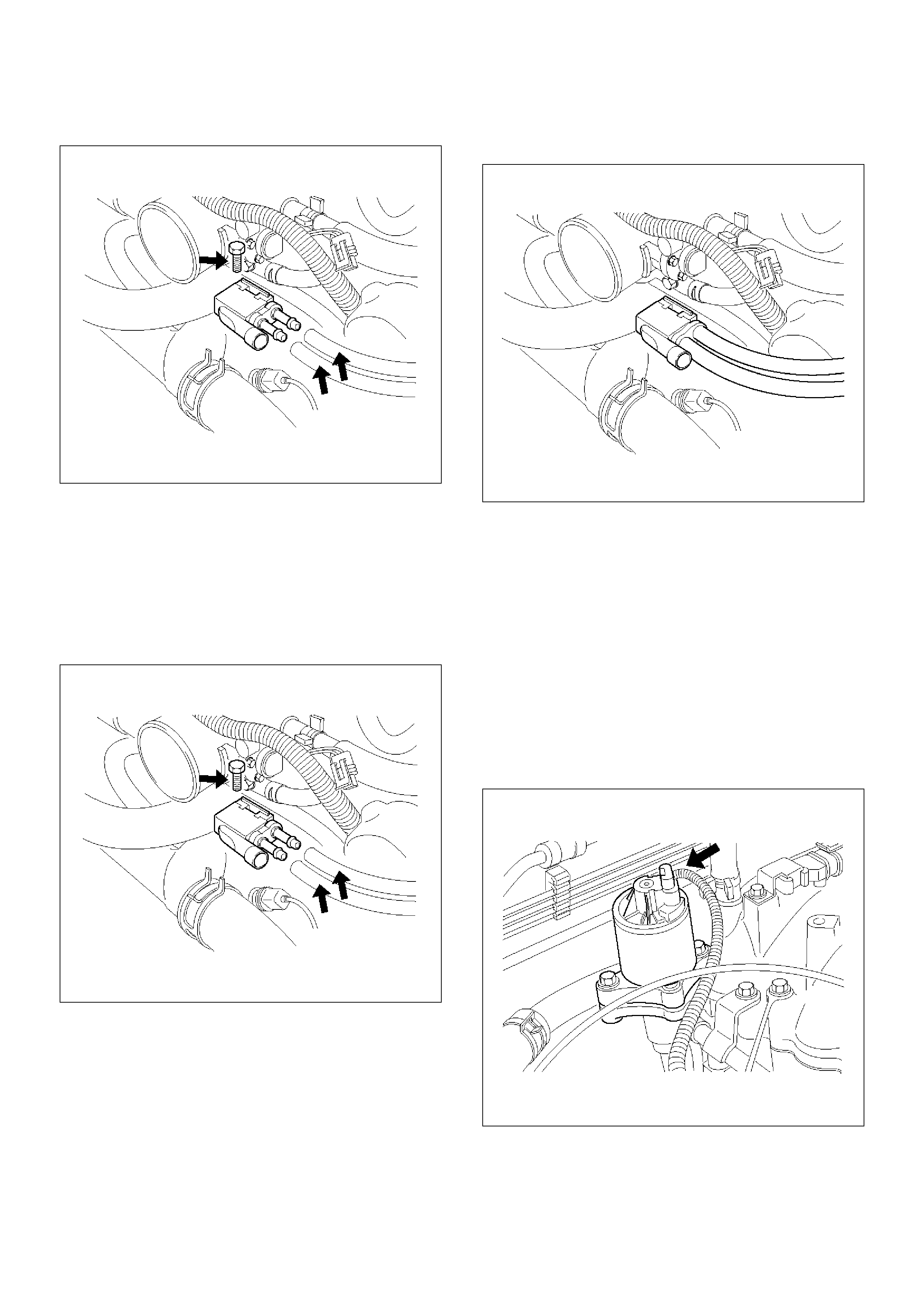
4.Remove the EVAP canister purge solenoid.
014RW137
Installation Procedure
1.Install the EVAP canister purge solenoid on the
upper intake manifold.
2.Install the EVAP canister purge solenoid retaining
bolt.
3.Connect the vacuum hoses to the EVAP canister
purge solenoid.
014RW137
4.Connect the electrical connector to the EVAP
canister purge solenoid.
014RW138
Fuel Tank Vent Valve
Removal and Installation Procedure
Refer to Fuel Pump
Linear Exhaust Gas Recirculation (EGR)
Valve
Removal Procedure
1. Disconnect the negative battery cable.
2. Disconnect the electrical connector at the EGR
valve.
014RW139
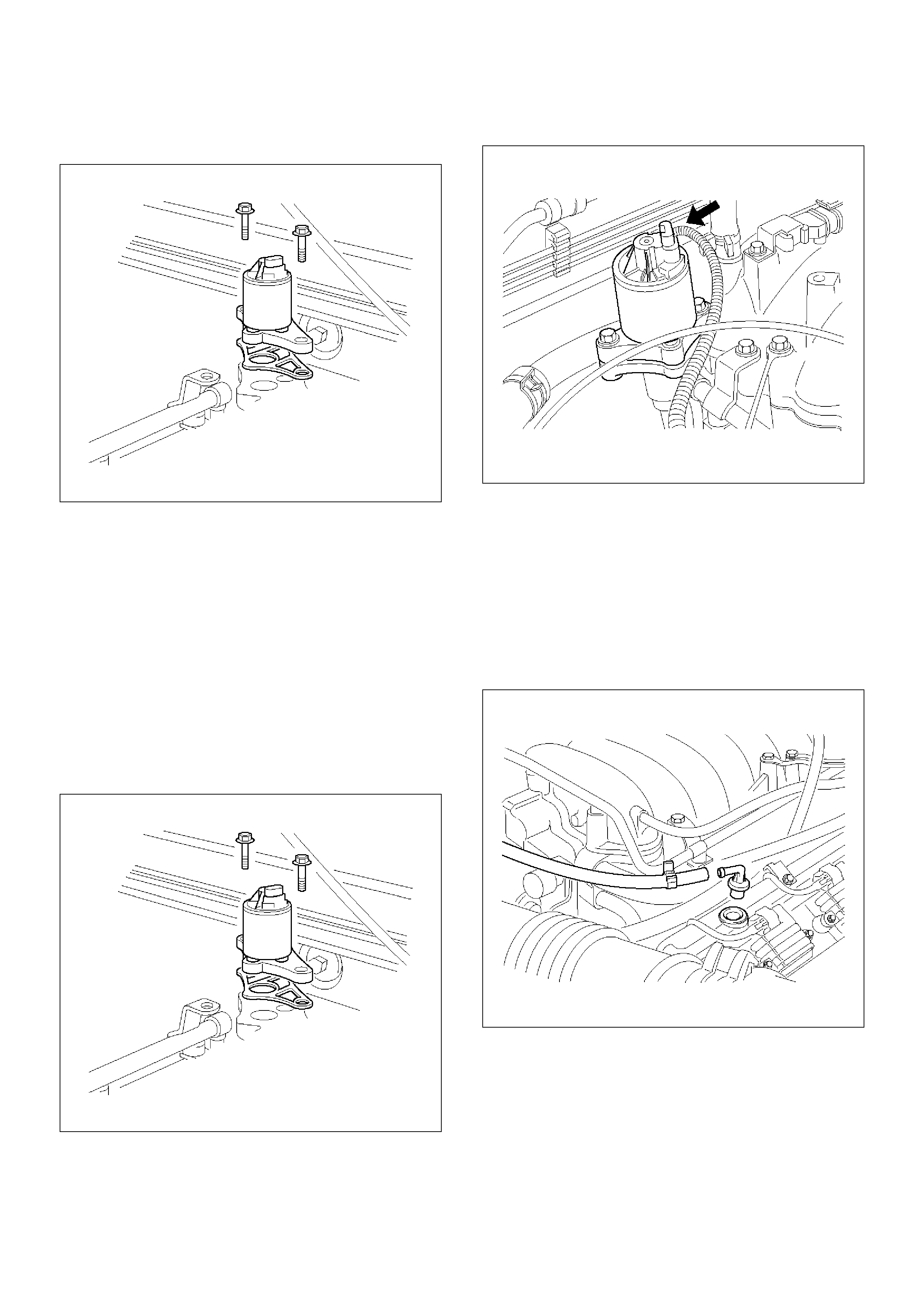
3. Remove the bolt and the nut from the upper intake
manifold.
014RW098
4. Remove the EGR valve from the upper intake
manifold.
5. Remove the gasket from the upper intake manifold.
Installation Procedure
1. Install the gasket on the upper intake manifold.
2. Install the EGR valve on the upper intake manifold.
3. Secure the EGR valve and the gasket with the bolt
and the nut.
NOTE: It is possible to install the EGR valve rotated
180° from the correct position. Make sure that the base
of the valve is placed so that it aligns with the mounting
flange.
014RW098
4. Connect the electrical connector at the EGR valve.
014RW139
5. Connect the negative battery cable.
Positive Crankcase Ventilation (PCV) Valve
Removal Procedure
1. Remove the vacuum hose at the PCV valve.
• Slide the clamp back to release the hose.
2. Pull the PCV valve from the rubber grommet in the
right valve cover.
014RW097
Inspection Procedure
1. Shake the valve and listen for the rattle of the
needle inside the valve.
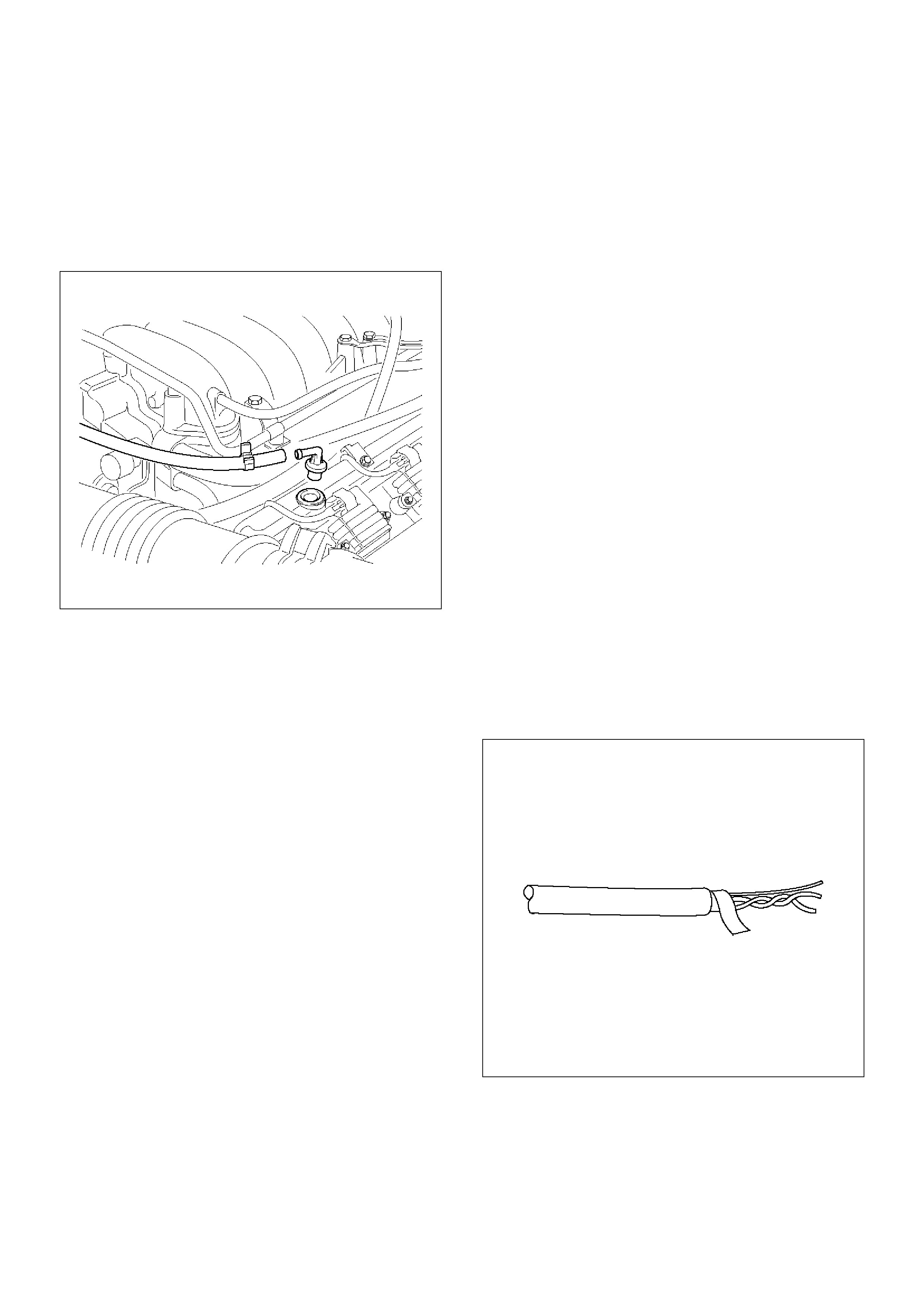
2.If the valve does not rattle, replace the valve.
Installation Procedure
1.Push the PCV valve into the rubber grommet in the
left valve cover.
2.Install the vacuum hose on the PCV valve and
secure the vacuum hose with the clamp.
014RW097
Wiring and Connectors
Wiring Harness Service
The control module harness electrically connects the
control module to the various solenoids, switches and
sensors in the vehicle engine compartment and
passenger compartment.
Replace wire harnesses with the proper part number
replacement.
Because of the low amperage and voltage levels utilized
in powertrain control systems, it is essential that all
wiring in environmentally exposed areas be repaired
with crimp and seal splice sleeves.
The following wire harness repair information is
intended as a general guideline only. Refer to Chassis
Electrical for all wire harness repair procedures.
Connectors and Terminals
Use care when probing a connector and when replacing
terminals. It is possible to short between opposite
terminals. Damage to components could result.
Always use jumper wires between connectors for circuit
checking. NEVER probe through Weather-Pack seals.
Use an appropriate connector test adapter kit which
contains an assortment of flexible connectors used to
probe terminals during diagnosis. Use an appropriate
fuse remover and test tool for removing a fuse and to
adapt the fuse holder to a meter for diagnosis.
Open circuits are often difficult to locate by sight
because oxidation or terminal misalignment are hidden
by the connectors. Merely wiggling a connector on a
sensor, or in the wiring harness, may temporarily correct
the open circuit. Intermittent problems may also be
caused by oxidized or loose connections.
Be certain of the type of connector/terminal before
making any connector or terminal repair. Weather-Pack
and Com-Pack III terminals look similar, but are
serviced differently.
PCM Connectors and Terminals
Removal Procedure
1. Remove the connector terminal retainer.
2. Push the wire connected to the affected terminal
through the connector face so that the terminal is
exposed.
3. Service the terminal as necessary.
Installation Procedure
1. Bend the tab on the connector to allow the terminal
to be pulled into position within the connector.
2. Pull carefully on the wire to install the connector
terminal retainer.
Wire Harness Repair: Twisted Shielded
Cable
Removal Procedure
1. Remove the outer jacket.
2. Unwrap the aluminum/mylar tape. Do not remove
the mylar.
047
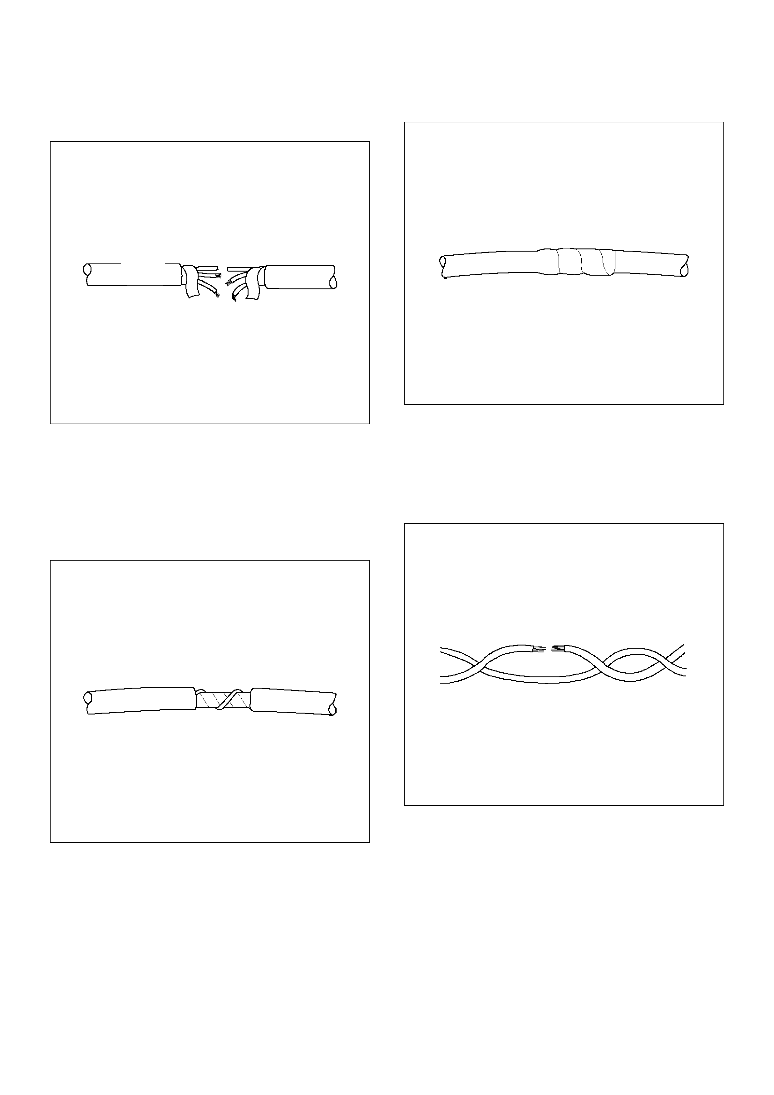
3. Untwist the conductors.
4. Strip the insulation as necessary.
048
Installation Procedure
1. Splice the wires using splice clips and rosin core
solder.
2. Wrap each splice to insulate.
3. Wrap the splice with mylar and with the drain
(uninsulated) wire.
049
4. Tape over the whole bundle to secure.
050
Twisted Leads
Removal Procedure
1. Locate the damaged wire.
2. Remove the insulation as required.
051
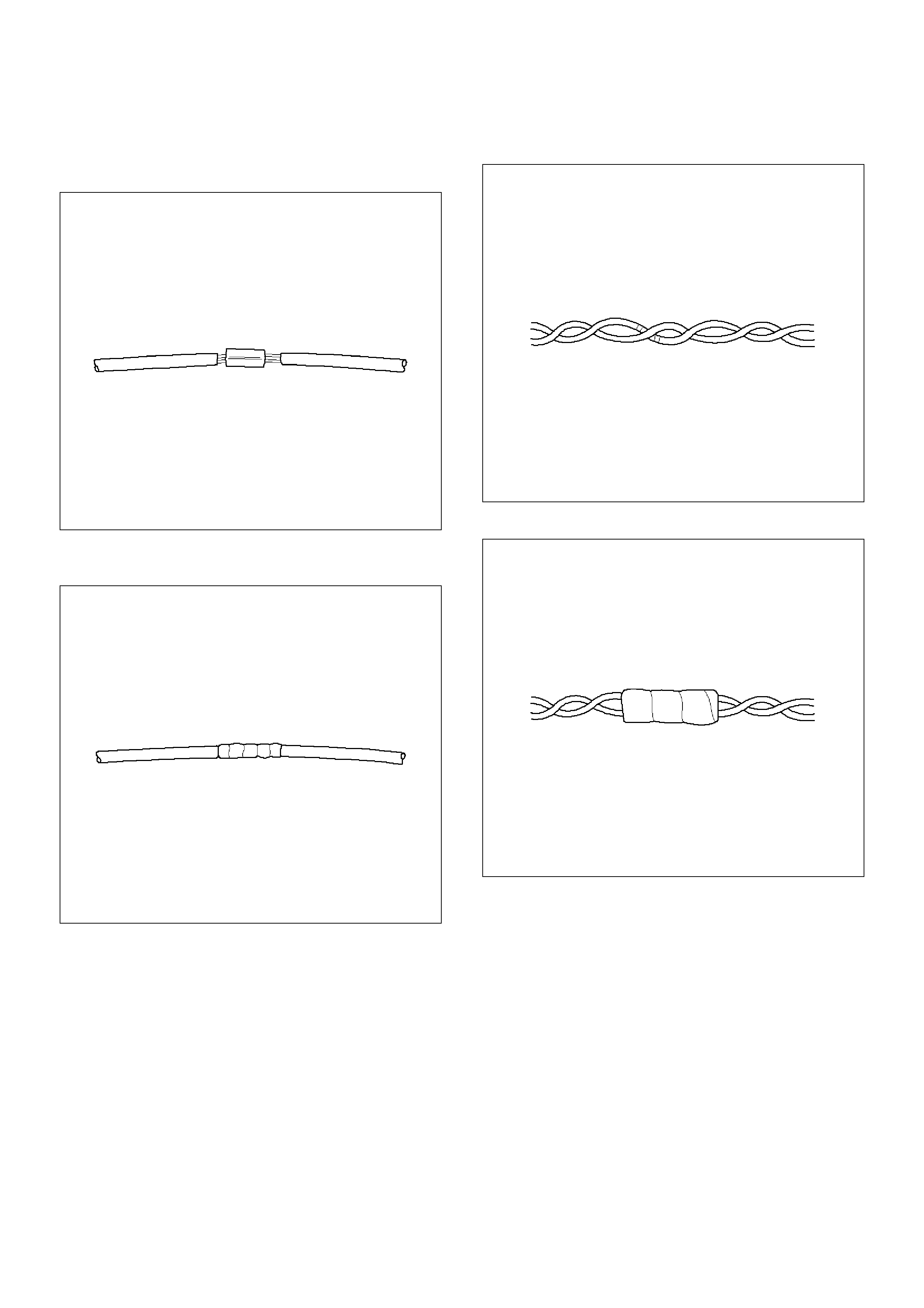
Installation Procedure
1. Use splice clips and rosin core solder in order to
splice the two wires together.
052
2. Cover the splice with tape in order to insulate it from
the other wires.
053
3. Twist the wires as they were before starting this
procedure.
054
4. Tape the wires with electrical tape. Hold in place.
055
Weather-Pack Connector
Tools Required
J 28742-A Weather-Pack II Terminal Remover
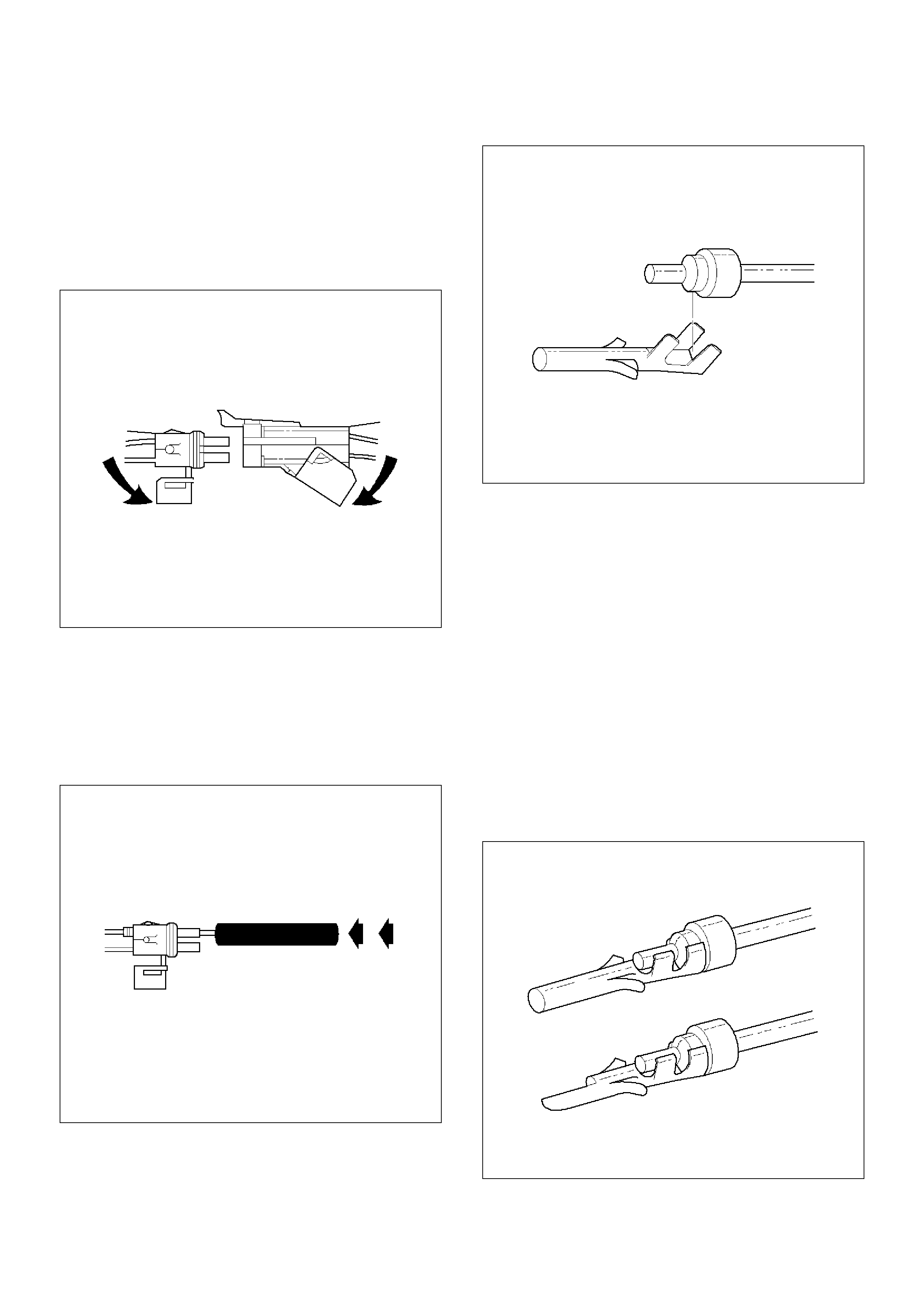
Removal Procedure
A Weather-Pack connector can be identified by a rubber
seal at the rear of the connector. This engine room
connector protects against moisture and dirt, which
could from oxidation and deposits on the terminals.
This protection is important, because of the low voltage
and the low amperage found in the electronic systems.
1. Open the secondary lock hinge on the connector.
070
2. Use tool J 28742-A or the equivalent to remove the
pin and the sleeve terminals. Push on J 28742-A to
release.
NOTE: Do the use an ordinary pick or the terminal may
be bent or deformed. Unlike standard blade terminals,
these terminals cannot be straightened after they have
been improperly bent.
071
3. Cut the wire immediately behind the cable seal.
072
Installation Procedure
Make certain the connectors are properly seated and all
of the sealing rings are in place when you reconnect the
leads. The secondary lock hinge provides a backup
locking feature for the connector. The secondary lock
hinge is used for added reliability. This flap should
retain the terminals even if the small terminal lock tangs
are not positioned properly.
Do not replace the Weather-Pack connections with
standard connections. Read the instructions provided
with the Weather-Pack connector and terminal
packages.
1. Replace the terminal.
2. Slip the new seal onto the wire.
3. Strip 5 mm (0.2") of insulation from the wire.
4. Crimp the terminal over the wire and the seal.
073
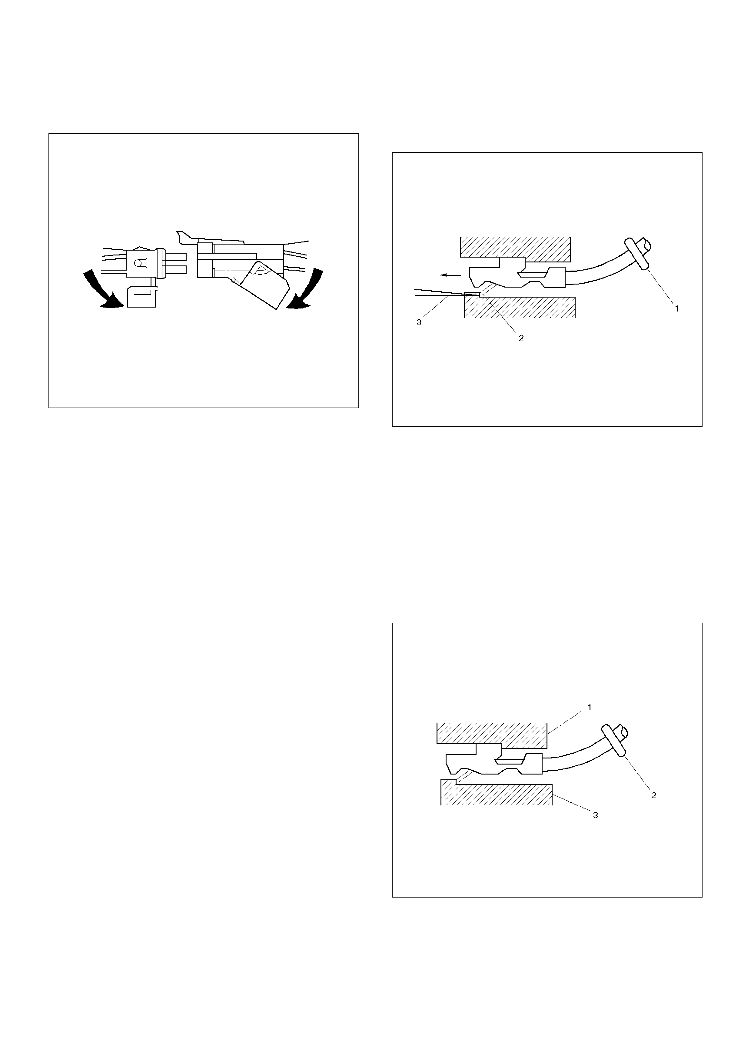
5. Push the terminal and the connector to engage the
locking tangs.
070
6. Close the secondary locking hinge.
Com-Pack III
General Information
The Com-Pack III terminal looks similar to some
Weather-Pack terminals. This terminal is not sealed
and is used where resistance to the environment is not
required. Use the standard method when repairing a
terminal. Do not use the Weather-Pack terminal tool J
28742-A or equivalent. These will damage the
terminals.
Metri-Pack
Tools Required
J 35689 Terminal Remover
Removal Procedure
Some connectors use terminals called Metri-Pack
Series 150. These may be used at the engine coolant
temperature (ECT) sensor.
1. Slide the seal (1) back on the wire.
2. Insert the J 35689 tool or equivalent (3) in order to
release the terminal locking tang (2).
060
3. Push the wire and the terminal out through the
connector. If you reuse the terminal, reshape the
locking tang.
Installation Procedure
Metri-Pack terminals are also referred to as
“pull-to-seat” terminals.
1. In order to install a terminal on a wire, the wire must
be inserted through the seal (2) and through the
connector (3).
2. The terminal (1) is then crimped onto the wire.
061
3. Then the terminal is pulled back into the connector
to seat it in place.
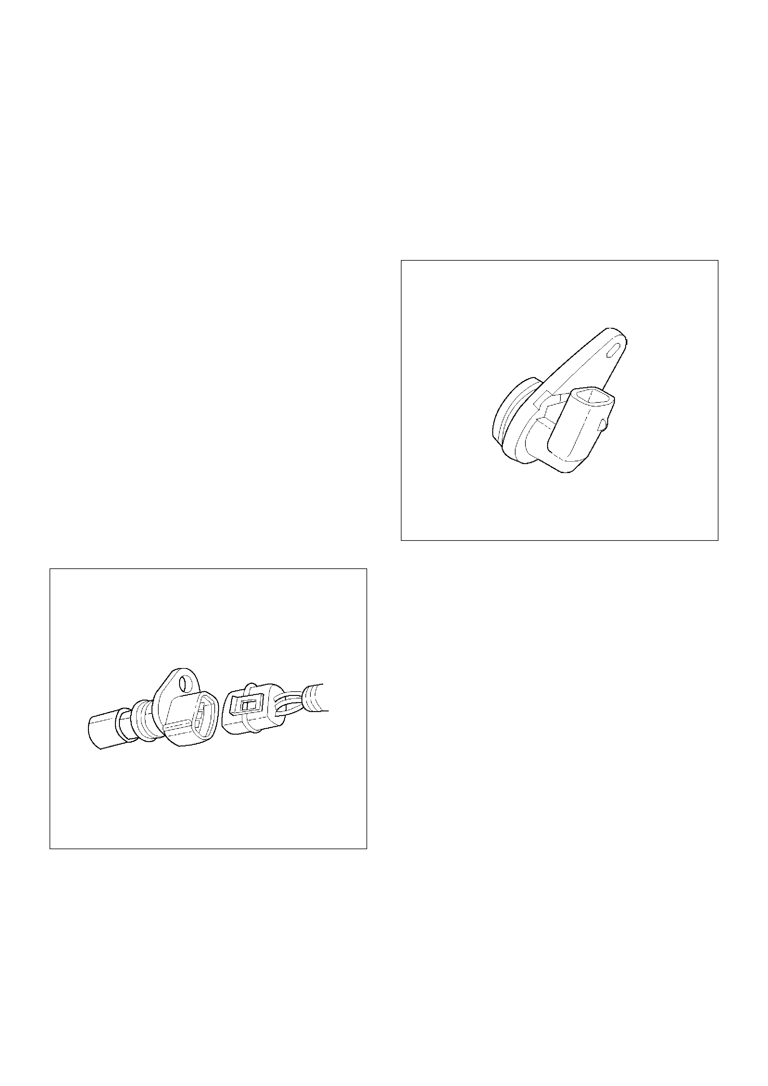
General Description (PCM and Sensors)
58X Reference PCM Input
The powertrain control module (PCM) uses this signal
from the crankshaft position (CKP) sensor to calculate
engine RPM and crankshaft position at all engine
speeds. The PCM also uses the pulses on this circuit to
initiate injector pulses. If the PCM receives no pulses
on this circuit, DTC P0337 will set. The engine will not
start and run without using the 58X reference signal.
A/C Request Signal
This signal tells the PCM when the A/C mode is
selected at the A/C control head. The PCM uses this to
adjust the idle speed before turning “ON” the A/C clutch.
The A/C compressor will be inoperative if this signal is
not available to the PCM.
Refer to A/C Clutch Circuit Diagnosis for A/C wiring
diagrams and diagnosis for the A/C electrical system.
Crankshaft Position (CKP) Sensor
The crankshaft position (CKP) sensor provides a signal
used by the powertrain control module (PCM) to
calculate the ignition sequence. The CKP sensor
initiates the 58X reference pulses which the PCM uses
to calculate RPM and crankshaft position.
Refer to Electronic Ignition System for additional
information.
0013
Camshaft Position (CMP) Sensor and
Signal
The camshaft position (CMP) sensor sends a CMP
signal to the PCM. The PCM uses this signal as a “sync
pulse” to trigger the injectors in the proper sequence.
The PCM uses the CMP signal to indicate the position
of the #1 piston during its power stroke. This allows the
PCM to calculate true sequential fuel injection (SFI)
mode of operation. If the PCM detects an incorrect
CMP signal while the engine is running, DTC P0341 will
set. If the CMP signal is lost while the engine is
running, t he fuel injection system will shift to a
calculated sequential fuel injection mode based on the
last fuel injection pulse, and the engine will continue to
run. As long as the fault is present, the engine can be
restarted. It will run in the calculated sequential mode
with a 1-in-6 chance of the injector sequence being
correct.
Refer to DTC P0341 for further information
0014
Engine Coolant Temperature (ECT) Sensor
The engine coolant temperature (ECT) sensor is a
thermistor (a resistor which changes value based on
temperature) mounted in the engine coolant stream.
Low coolant temperature produces a high resistance of
100,000 ohms at –40°C (–40°F). High temperature
causes a low resistance of 70 ohms at 130°C (266°F).
The PCM supplies a 5-volt signal to the ECT sensor
through resistors in the PCM and measures the
voltage. The signal voltage will be high when the
engine is cold and low when the engine is hot. By
measuring the voltage, the PCM calculates the engine
coolant temperature. Engine coolant temperature
affects most of the systems that the PCM controls.
Tech 2 displays engine coolant temperature in degrees.
After engine start-up, the temperature should rise
steadily to about 85°C (185°F). It then stabilizes when
the thermostat opens. If the engine has not been run for
several hours (overnight), the engine coolant
temperature and intake air temperature displays should
be close to each other. A hard fault in the engine
coolant sensor circuit will set DTC P0177 or DTC
P0118. An intermittent fault will set a DTC P1114 or
P1115.
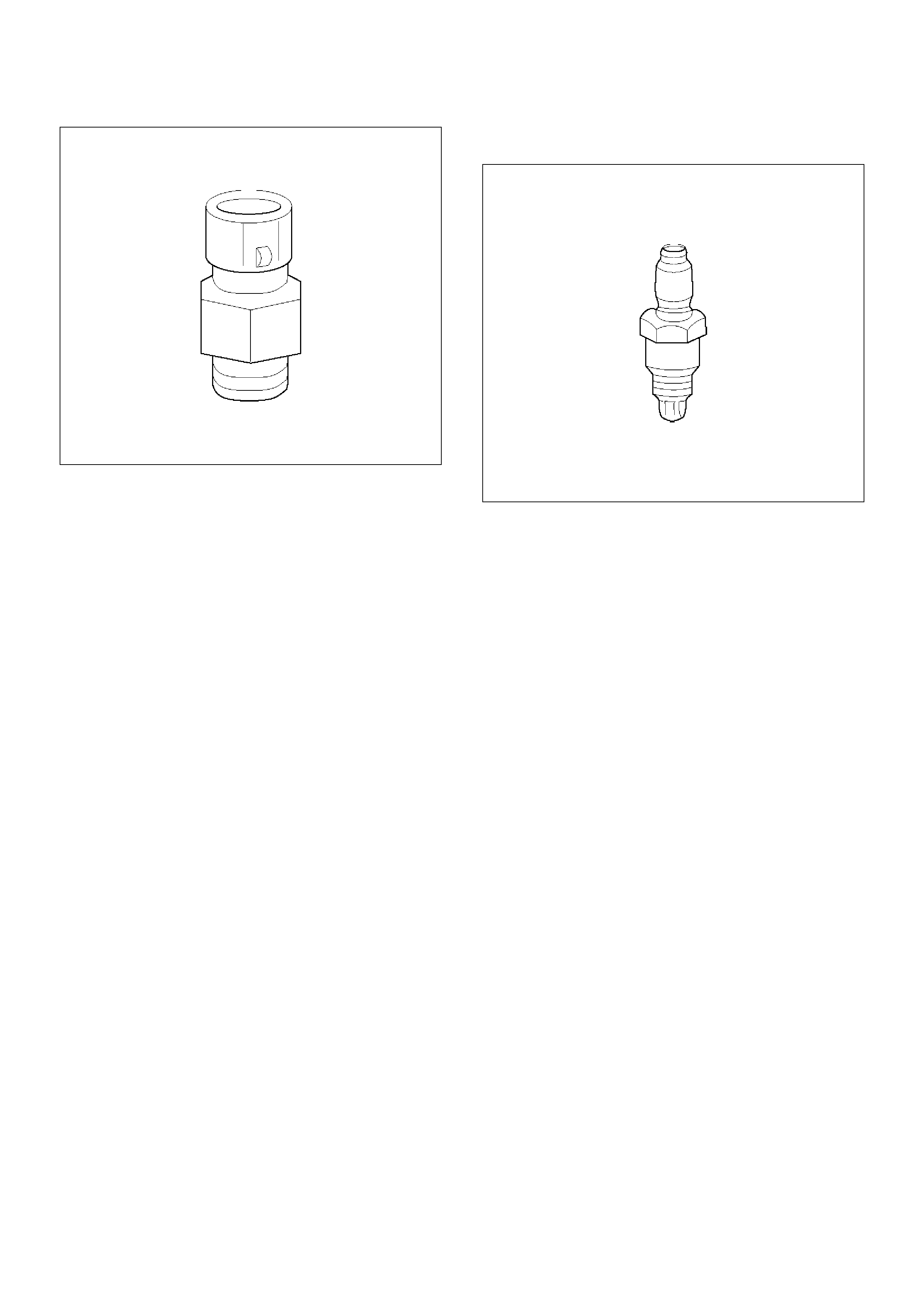
0016
Electrically Erasable Programmable Read
Only Memory (EEPROM)
The electrically erasable programmable read only
memory (EEPROM) is a permanent memory chip that is
physically soldered within the PCM. The EEPROM
contains the program and the calibration information
that the PCM needs to control powertrain operation.
Unlike the PROM used in past applications, the
EEPROM is not replaceable. If the PCM is replaced,
the new PCM will need to be programmed. Equipment
containing the correct program and calibration for the
vehicle is required to program the PCM.
Fuel Control Heated Oxygen Sensors
The fuel control heated oxygen sensors (Bank 1 HO2S
1 and Bank 2 HO2S 1) are mounted in the exhaust
stream where they can monitor the oxygen content of
the exhaust gas. The oxygen present in the exhaust
gas reacts with the sensor to produce a voltage output.
This voltage should constantly fluctuate from
approximately 100 mV to 900 mV. The heated oxygen
sensor voltage can be monitored with Tech 2. By
monitoring the voltage output of the oxygen sensor, the
PCM calculates the pulse width command for the
injectors to produce the proper combustion chamber
mixture.
• Low HO2S voltage is a lean mixture which will result
in a rich command to compensate.
• High HO2S voltage is a rich mixture which will result
in a lean command to compensate.
An open Bank 1 HO2S 1 signal circuit will set a DTC
P0134 and Tech 2 will display a constant voltage
between 400-500 mV. A constant voltage below 300
mV in the sensor circuit (circuit grounded) will set DTC
P0131. A constant voltage above 800 mV in the circuit
will set DTC P0132. Faults in the Bank 2 HO2S 1 signal
circuit will cause DTC 0154 (open circuit), DTC P0151
(grounded circuit), or DTC P0152 (signal voltage high)
to set.
0012
Intake Air Temperature (IAT) Sensor
The intake air temperature (IAT) sensor is a thermistor
which changes its resistance based on the temperature
of air entering the engine. Low temperature produces a
high resistance of 100,000 ohms at –40°C (–40°F).
High temperature causes low resistance of 70 ohms at
130°C (266°F) . The PCM supplies a 5-volt signal to the
sensor through a resistor in the PCM and monitors the
signal voltage. The voltage will be high when the
incoming air is cold. The voltage will be low when the
incoming air is hot. By measuring the voltage, the PCM
calculates the incoming air temperature. The IAT
sensor signal is used to adjust spark timing according to
the incoming air density.
Tech 2 displays the temperature of the air entering the
engine. The temperature should read close to the
ambient air temperature when the engine is cold and
rise as underhood temperature increases. If the engine
has not been run for several hours (overnight), the IAT
sensor temperature and engine coolant temperature
should read close to each other. A fault in the IAT
sensor circuit will set DTC P0112 or DTC P0113.
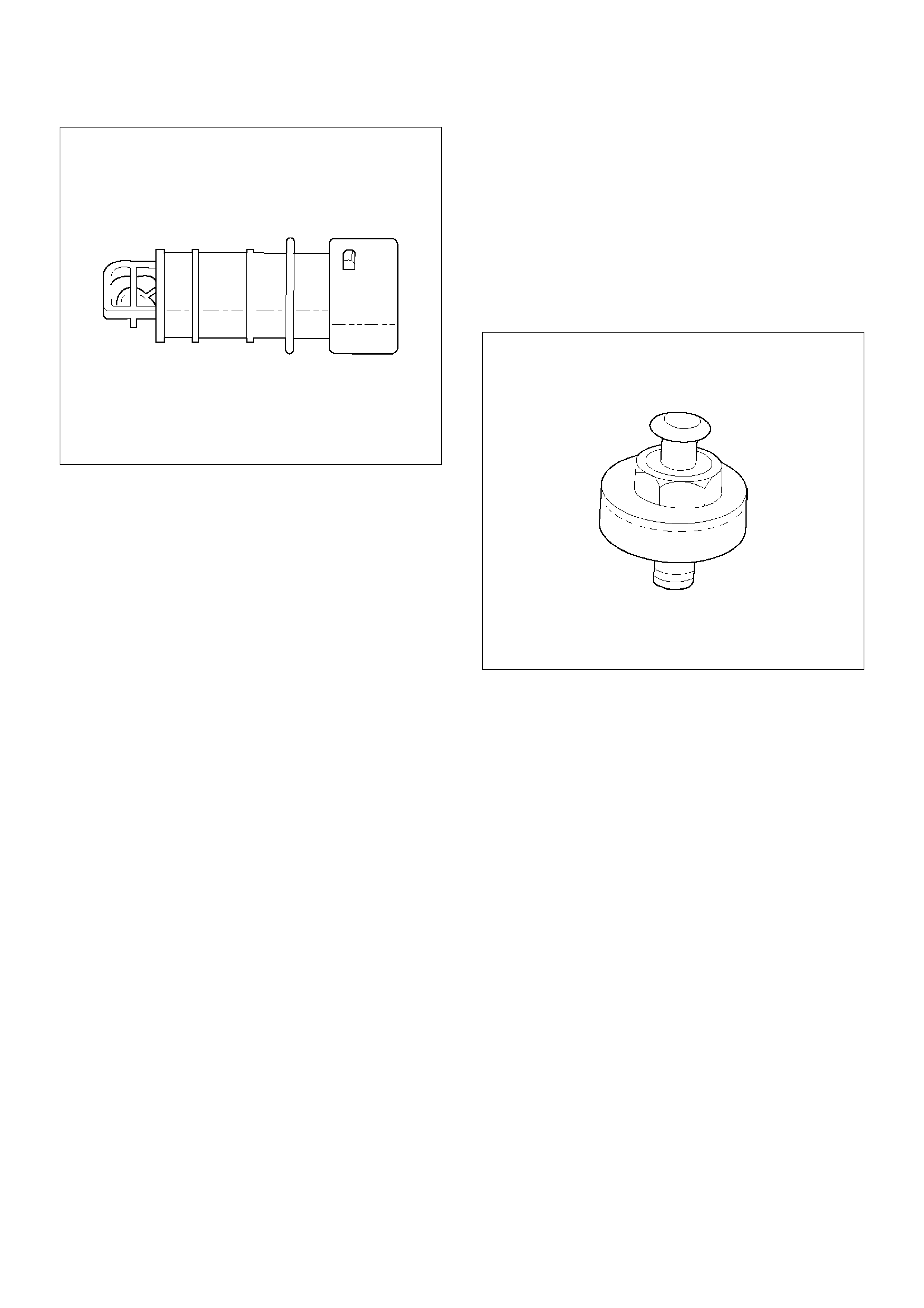
0018
Knock Sensor
Insufficient gasoline octane levels may cause
detonation in some engines. Detonation is an
uncontrolled explosion (burn) in the combustion
chamber. This uncontrolled explosion results from a
flame front opposite that of the normal flame front
produced by the spark plug. The rattling sound
normally associated with detonation is the result of two
or more opposing pressures (flame fronts) colliding
within the combustion chamber. Light detonation is
sometimes considered normal, but heavy detonation
could result in engine damage.
A knock sensor system is used to control detonation.
This system is designed to retard spark timing up to 20
degrees to reduce detonation in the engine. This allows
the engine to use maximum spark advance to improve
driveability and fuel economy.
The knock sensor system has two major components:
• The knock sensor (KS) module.
• The knock sensor.
The knock sensor, mounted in the engine block near the
cylinders, detects abnormal vibration in the engine. The
sensor produces an AC output signal of about 10
millivolts. The signal amplitude and frequency are
dependent on the amount of knock being experienced.
The signal voltage increases with the severity of the
knock. This signal voltage is input to the PCM. The
PCM then retards the ignition control (IC) spark timing
based on the KS signal being received.
The PCM determines whether knock is occurring by
comparing the signal level on the KS circuit with the
voltage level on the noise channel. The noise channel
allows the PCM to reject any false knock signal by
indicating the amount of normal engine mechanical
noise present. Normal engine noise varies depending
on the engine speed and load. If the voltage level on
the KS noise channel circuit is below the range
considered normal, DTC P0327 will set, indicating a
fault in the KS circuit or the knock sensor. If the PCM
determines that an abnormal minimum or maximum
noise level is being experienced, DTC P0325 will set.
The PCM contains a knock sensor (KS) module. The
KS module contains the circuitry which allows the PCM
to utilize the KS signal and diagnose the KS sensor and
the KS circuitry. If the KS module is missing or faulty, a
continuous knock condition will be indicated, and the
PCM will set DTC P0325.
Although it is a plug-in device, the KS module is not
replaceable. If the KS module is faulty, the entire PCM
must be replaced.
0009
Linear Exhaust Gas Recirculation (EGR)
Control
The PCM monitors the exhaust gas recirculation (EGR)
actual position and adjusts the pintle position
accordingly. The PCM uses information from the
following sensors to control the pintle position:
• Engine coolant temperature (ECT) sensor.
• Throttle position (TP) sensor.
• Mass air flow (MAF) sensor.
Mass Air Flow (MAF) Sensor
The mass air flow (MAF) sensor measures the
difference between the volume and the quantity of air
that enters the engine. “Volume”means the size of the
space to be filled. “Quantity”means the number of air
molecules that will fit into the space. This information is
important to the PCM because heavier, denser air will
hold more fuel than lighter, thinner air. The PCM adjusts
the air/fuel ratio as needed depending on the MAF
value. Tech 2 reads the MAF value and displays it in
terms of grams per second (gm/s). At idle, Tech 2
should read between 4-7 gm/s on a fully warmed up
engine. Values should change quickly on acceleration.
Values should remain stable at any given RPM. A
failure in the MAF sensor or circuit will set DTC P0101,
DTC P0102, or DTC P0103.
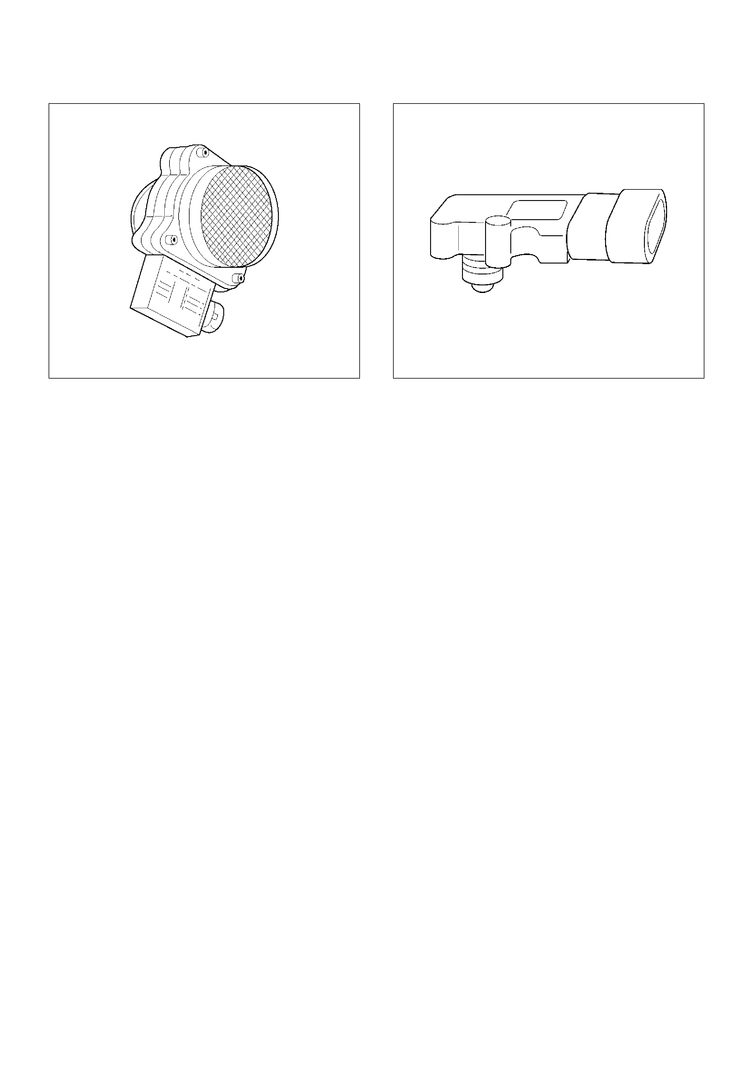
0007
Manifold Absolute Pressure (MAP) Sensor
The manifold absolute pressure (MAP) sensor responds
to changes in intake manifold pressure (vacuum). The
MAP sensor signal voltage to the PCM varies from
below 2 volts at idle (high vacuum) to above 4 volts with
the ignition ON, engine not running or at wide-open
throttle (low vacuum).
The MAP sensor is used to determine the following:
•Manifold pressure changes while the linear EGR flow
test diagnostic is being run.
• Engine vacuum level for other diagnostics.
• Barometric pressure (BARO).
If the PCM detects a voltage that is lower than the
possible range of the MAP sensor, DTC P0107 will be
set. A signal voltage higher than the possible range of
the sensor will set DTC P0108. An intermittent low or
high voltage will set DTC P1107 or DTC P1106,
respectively. The PCM can detect a shifted MAP
sensor. The PCM compares the MAP sensor signal to a
calculated MAP based on throttle position and various
engine load factors. If the PCM detects a MAP signal
that varies excessively above or below the calculated
value, DTC P0106 will set.
055RW004
Powertrain Control Module (PCM)
The powertrain control module (PCM) is located in the
passenger compartment below the center console. The
PCM controls the following:
• Fuel metering system.
• Transmission shifting (automatic transmission only).
• Ignition timing.
• On-board diagnostics for powertrain functions.
The PCM constantly observes the information from
various sensors. The PCM controls the systems that
affect vehicle performance. The PCM performs the
diagnostic function of the system. It can recognize
operational problems, alert the driver through the MIL
(Service Engine Soon lamp), and store diagnostic
trouble codes (DTCs). DTCs identify the problem areas
to aid the technician in making repairs.
This engine uses 2 different control modules:
• IPCM-6KT for automatic transmission-equipped
vehicles.
• ISFI-6 for manual transmission-equipped vehicles.
PCM Function
The PCM supplies either 5 or 12 volts to power various
sensors or switches. The power is supplied through
resistances in the PCM which are so high in value that a
test light will not light when connected to the circuit. In
some cases, even an ordinary shop voltmeter will not
give an accurate reading because its resistance is too
low. Therefore, a digital voltmeter with at least 10
megohms input impedance is required to ensure
accurate voltage readings. Tool J 39200 meets this
requirement. The PCM controls output circuits such as
the injectors, IAC, cooling fan relays, etc., by controlling
the ground or the power feed circuit through transistors
of following device.
• Output Driver Module (ODM)
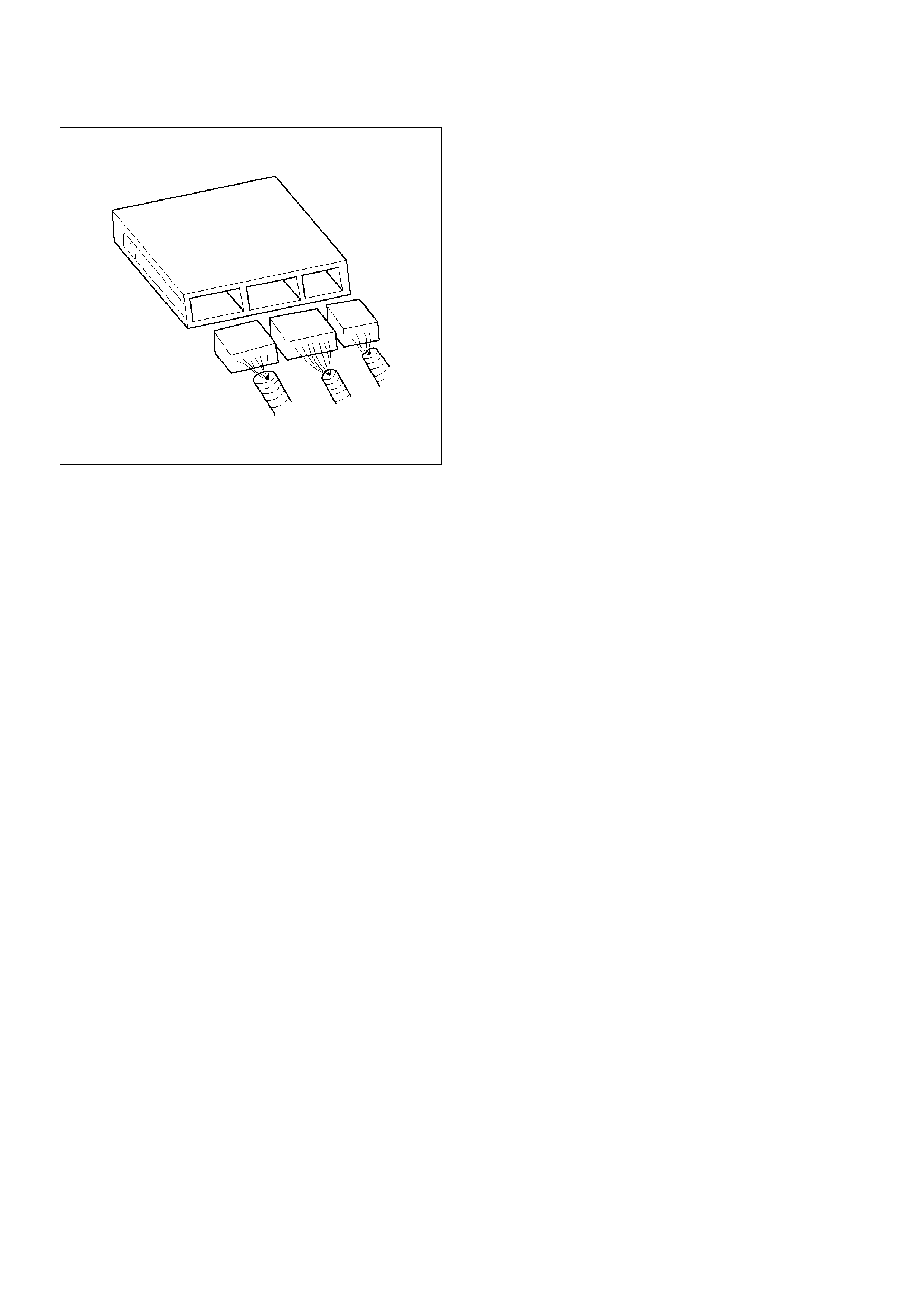
0005
PCM Components
The PCM is designed to maintain exhaust emission
levels to government mandated standards while
providing excellent driveability and fuel efficiency. The
PCM monitors numerous engine and vehicle functions
via electronic sensors such as the throttle position (TP)
sensor, heated oxygen sensor (HO2S), and vehicle
speed sensor (VSS). The PCM also controls certain
engine operations through the following:
•Fuel injector control
•Ignition control module
•Knock sensor
•Automatic transmission shift functions
•Cruise control
•A/C clutch control
PCM Voltage Description
The PCM supplies a buffered voltage to various
switches and sensors. It can do this because
resistance in the PCM is so high in value that a test light
may not illuminate when connected to the circuit. An
ordinary shop voltmeter may not give an accurate
reading because the voltmeter input impedance is too
low. Use a 10-megohm input impedance digital
voltmeter (such as J 39200) to assure accurate voltage
readings.
The input/output devices in the PCM include
analog-to-digital converters, signal buffers, counters,
and special drivers. The PCM controls most
components with electronic switches which complete a
ground circuit when turned “ON.” These switches are
arranged in groups of 4 and 7, called either a
surface-mounted quad driver module (QDM), which can
independently control up to 4 output terminals, or QDMs
which can independently control up to 7 outputs. Not all
outputs are always used.
PCM Input/Outputs
Inputs – Operating Conditions Read
•Air Conditioning “ON” or “OFF”
•Engine Coolant Temperature
•Crankshaft Position
•Exhaust Oxygen Content
•Electronic Ignition
•Manifold Absolute Pressure
•Battery Voltage
•Throttle Position
•Vehicle Speed
•Fuel Pump Voltage
•Power Steering Pressure
•Intake Air Temperature
•Mass Air Flow
•Engine Knock
•Camshaft Position
Outputs – Systems Controlled
•Exhaust Gas Recirculation (EGR)
•Ignition Control
•Fuel Control
•Idle Air Control
•Electric Fuel Pump
•Air Conditioning
•Diagnostics
–Malfunction Indicator Lamp (Service Engine Soon
lamp)
–Data Link Connector (DLC)
–Data Output
•Transmission Control Module
•Alternator Gain Control
PCM Service Precautions
The PCM is designed to withstand normal current draws
associated with vehicle operation. Avoid overloading
any circuit. When testing for opens and shorts, do not
ground or apply voltage to any of the PCM's circuits
unless instructed to do so. These circuits should only
be tested Tech-2. The PCM should remain connected
to the PCM or to a recommended breakout box.
Reprogramming The PCM
The Service Programming System (SPS) allows
reprogramming of the PCM without removing it from the
vehicle . This provides a flexible and cost-effective
method of making changes in software calibrations.
The service programming system (SPS) will not allow
incorrect software programming or incorrect calibration
changes.
Refer to Sections 0C1 - Service Programming System
and 11A1 - 6VE1 Immobiliser.

Throttle Position (TP) Sensor
The throttle position (TP) sensor is a potentiometer
connected to the throttle shaft on the throttle body. The
PCM monitors the voltage on the signal line and
calculates throttle position. As the throttle valve angle is
changed (accelerator pedal moved), the TP sensor
signal also changes. At a closed throttle position, the
output of the TP sensor is low. As the throttle valve
opens, the output increases so that at wide open throttle
(WOT), the output voltage should be above 4 volts.
The PCM calculates fuel delivery based on throttle
valve angle (driver demand). A broken or loose TP
sensor may cause intermittent bursts of fuel from an
injector and unstable idle because the PCM thinks the
throttle is moving. A hard failure in the TP sensor 5-volt
reference or signal circuits will set a DTC P0123. A
hard failure with the TP sensor ground circuit may set
DTC P0123. Once a DTC is set, the PCM will use an
artificial default value based on engine RPM and mass
air flow for the throttle position, and some vehicle
performance will return. A high idle may result when
DTC P0123 is set. The PCM can also detect a shifted
TP sensor. The PCM monitors throttle position and
compares the actual TP sensor reading to a predicted
TP value calculated from engine speed. If the PCM
detects an out-of-range condition, DTC P0121 will be
set.
0021
Transmission Fluid Temperature (TFT)
Sensor
The transmission fluid temperature sensor is a
thermistor which changes its resistance based on the
temperature of the transmission fluid. For a complete
description of the TFT sensor, refer to 4L30-E
Automatic Transmission Diagnosis.
A failure in the TFT sensor or associated wiring will
cause DTC P0712 or DTC P0713 to set. In this case,
engine coolant temperature will be substituted for the
TFT sensor value and the transmission will operate
normally.
Transmission Range Switch
Important: The vehicle should not be driven with the
transmission range switch disconnected; idle quality will
be affected.
The four inputs from the transmission range switch
indicate to the PCM which position is selected by the
transmission selector lever. This information is used for
ignition timing, EVAP canister purge, EGR and IAC
valve operation.
For more information on the transmission on the
transmission range switch, refer to 4L30-E Automatic
Transmission.
Vehicle Speed Sensor (VSS)
The PCM determines the speed of the vehicle by
converting a plusing voltage signal from the vehicle
speed sensor (VSS) into miles per hour. The PCM uses
this signal to operate the cruise control, speedometer,
and the TCC and shift solenoids in the transmission. For
more information on the TCC and shift solenoids, refer
to 4L30-E Automatic Transmission.
0008
Use of Circuit Testing Tools
Do not use a test light to diagnose the powertrain
electrical systems unless specifically instructed by the
diagnostic procedures. Use Connector Test Adapter Kit
J 35616 whenever diagnostic procedures call for
probing connectors.
Aftermarket Electrical and Vacuum
Equipment
Aftermarket (add-on) electrical and vacuum equipment
is defined as any equipment which connects to the
vehicle's electrical or vacuum systems that is installed
on a vehicle after it leaves the factory. No allowances
have been made in the vehicle design for this type of
equipment.
NOTE: No add-on vacuum equipment should be added
to this vehicle.
NOTE: Add-on electrical equipment must only be
connected to the vehicle's electrical system at the
battery (power and ground).
Add-on electrical equipment, even when installed to
these guidelines, may still cause the powertrain system
to malfunction. This may also include equipment not
connected to the vehicle electrical system such as
portable telephones and radios. Therefore, the first step
in diagnosing any powertrain problem is to eliminate all
aftermarket electrical equipment from the vehicle. After
this is done, if the problem still exists, it may be
diagnosed in the normal manner.
Electrostatic Discharge Damage
Electronic components used in the PCM are often
designed to carry very low voltage. Electronic
components are susceptible to damage caused by
electrostatic discharge. Less than 100 volts of static
electricity can cause damage to some electronic
components. By comparison, it takes as much as 4000
volts for a person to feel even the zap of a static
discharge.
TS23793
There are several ways for a person to become
statically charged. The most common methods of
charging are by friction and induction.
•An example of charging by friction is a person sliding
across a vehicle seat.
•Charge by induction occurs when a person with well
insulated shoes stands near a highly charged object
and momentary touches ground. Charges of the
same polarity are drained off leaving the person
highly charged with the opposite polarity. Static
charges can cause damage, therefore it is important
to use care when handling and testing electronic
components.
NOTE: To prevent possible electrostatic discharge
damage, follow these guidelines:
•Do not touch the PCM connector pins or soldered
components on the PCM circuit board.
•Do not touch the knock sensor module component
leads.
•Do not open the replacement part package until the
part is ready to be installed.
•Before removing the part from the package, ground
the package to a known good ground on the vehicle.
•If the part has been handled while sliding across the
seat, while sitting down from a standing position, or
while walking a distance, touch a known good ground
before installing the part.
Upshift Lamp
Refer to Manual Transmission.
General Description (Air Induction)
Air Induction System
The air induction system filters contaminants from the
outside air, and directs the progress of the air as it is
drawn into the engine. A remote-mounted air cleaner
prevents dirt and debris in the air from entering the
engine. The air duct assembly routes filtered air to the
throttle body. Air enters the engine by to following
steps:
1. Through the throttle body.
2. Into the common chamber.
3. Through the cylinder head intake ports.
4. Into the cylinders.
055RV010
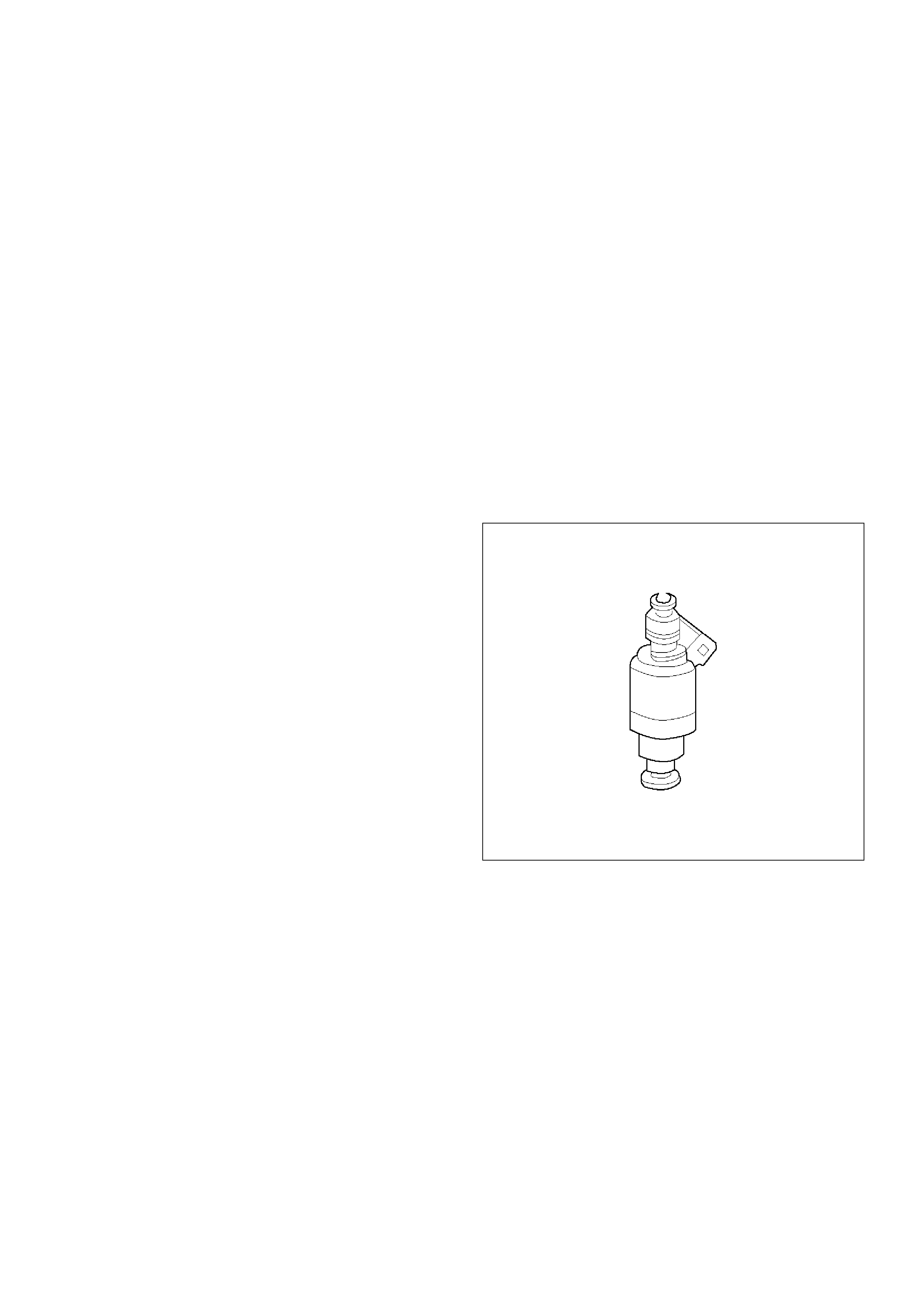
General Description (Fuel Metering)
Acceleration Mode
The PCM provides extra fuel when it detects a rapid
increase in the throttle position and the air flow.
Accelerator Controls
The accelerator control system is a cable-type system
with specific linkage adjustments.
Refer to Cable Adjustment.
Battery Voltage Correction Mode
When battery voltage is low, the PCM will compensate
for the weak spark by increasing the following:
•The amount of fuel delivered.
•The idle RPM.
•Ignition dwell time.
CMP Signal
The PCM uses this signal to determine the position of
the number 1 piston during its power stroke, allowing
the PCM to calculate true sequential multiport fuel
injection (SFI). Loss of this signal will set a DTC P0341.
If the CMP signal is lost while the engine is running, the
fuel injection system will shift to a calculated sequential
fuel injection based on the last fuel injection pulse, and
the engine will continue to run. The engine can be
restarted and will run in the calculated sequential mode
as long as the fault is present, with a 1-in-6 chance of
being correct.
Clear Flood Mode
Clear a flooded engine by pushing the accelerator pedal
down all the way. The PCM then de-energizes the fuel
injectors. The PCM holds the fuel injectors
de-energized as long as the throttle remains above 80%
and the engine speed is below 800 RPM. If the throttle
position becomes less than 80%, the PCM again begins
to pulse the injectors “ON” and “OFF,” allowing fuel into
the cylinders.
Deceleration Mode
The PCM reduces the amount of fuel injected when it
detects a decrease in the throttle position and the air
flow. When deceleration is very fast, the PCM may cut
off fuel completely for short periods.
Engine Speed Fuel Disable Mode
The PCM monitors engine speed. It turns off the fuel
injectors when the engine speed increase above 6400
RPM. The fuel injectors are turned back on when
engine speed decreases below 6150 RPM.
Fuel Cutoff Mode
No fuel is delivered by the fuel injectors when the
ignition is “OFF.” This prevents engine run-on. In
addition, the PCM suspends fuel delivery if no reference
pulses are detected (engine not running) to prevent
engine flooding.
Fuel Injector
The sequential multiport fuel injection (SFI) fuel injector
is a solenoid-operated device controlled by the PCM.
The PCM energizes the solenoid, which opens a valve
to allow fuel delivery.
The fuel is injected under pressure in a conical spray
pattern at the opening of the intake valve. Excess fuel
not used by the injectors passes through the fuel
pressure regulator before being returned to the fuel
tank.
A fuel injector which is stuck partly open will cause a
loss of fuel pressure after engine shut down, causing
long crank times.
0003
Fuel Metering System Components
The fuel metering system is made up of the following
parts:
• The fuel injectors.
• The throttle body.
• The fuel rail.
• The fuel pressure regulator.
• The PCM.
• The crankshaft position (CKP) sensor.
• The camshaft position (CMP) sensor.
• The idle air control (IAC) valve.
• The fuel pump.
• The fuel pump relay.

Basic System Operation
The fuel metering system starts with the fuel in the fuel
tank. An electric fuel pump, located in the fuel tank,
pumps fuel to the fuel rail through an in-line fuel filter.
The pump is designed to provide fuel at a pressure
above the pressure needed by the injectors. A fuel
pressure regulator in the fuel rail keeps fuel available to
the fuel injectors at a constant pressure. A return line
delivers unused fuel back to the fuel tank. Refer to
Section 6C for further information on the fuel tank, line
filter, and fuel pipes.
Fuel Metering System Purpose
The basic function of the air/fuel metering system is to
control the air/fuel delivery to the engine. Fuel is
delivered to the engine by individual fuel injectors
mounted in the intake manifold near each intake valve.
The main control sensor is the heated oxygen sensor
(HO2S) located in the exhaust system. The HO2S tells
the PCM how much oxygen is in the exhaust gas. The
PCM changes the air/fuel ratio to the engine by
controlling the amount of time that fuel injector is “ON.”
The best mixture to minimize exhaust emissions is 14.7
parts of air to 1 part of petrol by weight, which allows the
catalytic converter to operate most efficiently. Because
of the constant measuring and adjusting of the air/fuel
ratio, the fuel injection system is called a “closed loop”
system.
The PCM monitors signals from several sensors in
order to determine the fuel needs of the engine. Fuel is
delivered under one of several conditions called
“modes.” All modes are controlled by the PCM.
Fuel Pressure Regulator
The fuel pressure regulator is a diaphragm-operated
relief valve mounted on the fuel rail with fuel pump
pressure on one side and manifold pressure on the
other side. The fuel pressure regulator maintains the
fuel pressure available to the injector at three times
barometric pressure adjusted for engine load. It may be
serviced separate.
If the pressure is too low, poor performance and a DTC
P0131, DTC P0151,DTC P0171 or DTC P1171 will be
the result. If the pressure is too high, excessive odor
and/or a DTC P0132, DTC P0152,DTC P0172 or DTC
P0175 will be the result. Refer to Fuel System
Diagnosis for information on diagnosing fuel pressure
conditions.
0011
Fuel Pump Electrical Circuit
When the key is first turned “ON,” the PCM energizes
the fuel pump relay for two seconds to build up the fuel
pressure quickly. If the engine is not started within two
seconds, the PCM shuts the fuel pump off and waits
until the engine is cranked. When the engine is cranked
and the 58 X crankshaft position signal has been
detected by the PCM, the PCM supplies 12 volts to the
fuel pump relay to energize the electric in-tank fuel
pump.
An inoperative fuel pump will cause a “no-start”
condition. A fuel pump which does not provide enough
pressure will result in poor performance.
Fuel Rail
The fuel rail is mounted to the top of the engine and
distributes fuel to the individual injectors. Fuel is
delivered to the fuel inlet tube of the fuel rail by the fuel
lines. The fuel goes through the fuel rail to the fuel
pressure regulator. The fuel pressure regulator
maintains a constant fuel pressure at the injectors.
Remaining fuel is then returned to the fuel tank.
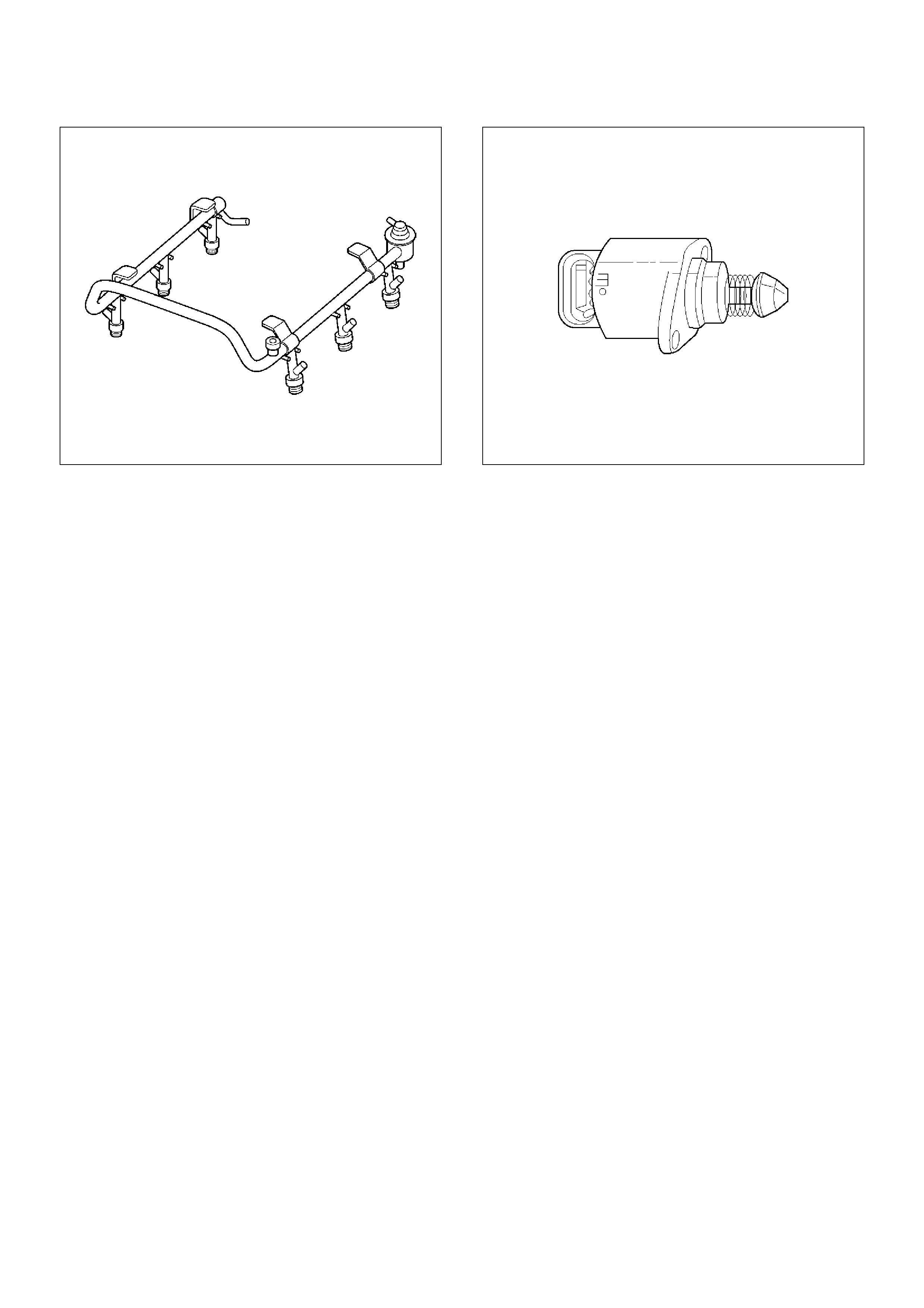
055RW009
Idle Air Control (IAC) Valve
The purpose of the idle air control (IAC) valve is to
control engine idle speed, while preventing stalls due to
changes in engine load. The IAC valve, mounted in the
throttle body, controls bypass air around the throttle
plate. By moving the conical valve (pintle) in (to
decrease air flow) or out (to increase air flow), a
controlled amount of air can move around the throttle
plate. If the RPM is too low, the PCM will retract the IAC
pintle, resulting in more air moving past the throttle plate
to increase the RPM. If the RPM is too high, the PCM
will extend the IAC pintle, allowing less air to move past
the throttle plate, decreasing the RPM.
The IAC pintle valve moves in small steps called counts.
During idle, the proper position of the IAC pintle is
calculated by the PCM based on battery voltage,
coolant temperature, engine load, and engine RPM. If
the RPM drops below a specified value, and the throttle
plate is closed, the PCM senses a near-stall condition.
The PCM will then calculate a new IAC pintle valve
position to prevent stalls.
If the IAC valve is disconnected and reconnected with
the engine running, the idle RPM will be wrong. In this
case, the IAC must be reset. The IAC resets when the
key is cycled “ON” then “OFF.” When servicing the IAC,
it should only be disconnected or connected with the
ignition “OFF.”
The position of the IAC pintle valve affects engine
start-up and the idle characteristics of the vehicle. If the
IAC pintle is fully open, too much air will be allowed into
the manifold. This results in high idle speed, along with
possible hard starting and a lean air/fuel ratio. DTC
P0507 or DTC P1509 may set. If the IAC pintle is stuck
closed, too little air will be allowed in the manifold. This
results in a low idle speed, along with possible hard
starting and a rich air/fuel ratio. DTC P0506 or DTC
P1508 may set. If the IAC pintle is stuck part-way
open, the idle may be high or low and will not respond to
changes in the engine load.
0006
Run Mode
The run mode has the following two conditions:
• Open loop
• Closed loop
When the engine is first started the system is in “open
loop” operation. In “open loop,” the PCM ignores the
signal from the heated oxygen sensor (HO2S). It
calculates the air/fuel ratio based on inputs from the TP,
ECT, and MAF sensors.
The system remains in “open loop” until the following
conditions are met:
• The HO2S has a varying voltage output showing that
it is hot enough to operate properly (this depends on
temperature).
• The ECT has reached a specified temperature.
• A specific amount of time has elapsed since starting
the engine.
• Engine speed has been greater than a specified RPM
since start-up.
The specific values for the above conditions vary with
different engines and are stored in the programmable
read only memory (PROM). When these conditions are
met, the system enters “closed loop” operation. In
“closed loop,” the PCM calculates the air/fuel ratio
(injector on-time) based on the signal from the HO2S.
This allows the air/fuel ratio to stay very close to 14.7:1.
Starting Mode
When the ignition is first turned “ON,” the PCM
energizes the fuel pump relay for two seconds to allow
the fuel pump to build up pressure. The PCM then
checks the engine coolant temperature (ECT) sensor
and the throttle position (TP) sensor to determine the
proper air/fuel ratio for starting.
The PCM controls the amount of fuel delivered in the
starting mode by adjusting how long the fuel injectors
are energized by pulsing the injectors for very short
times.
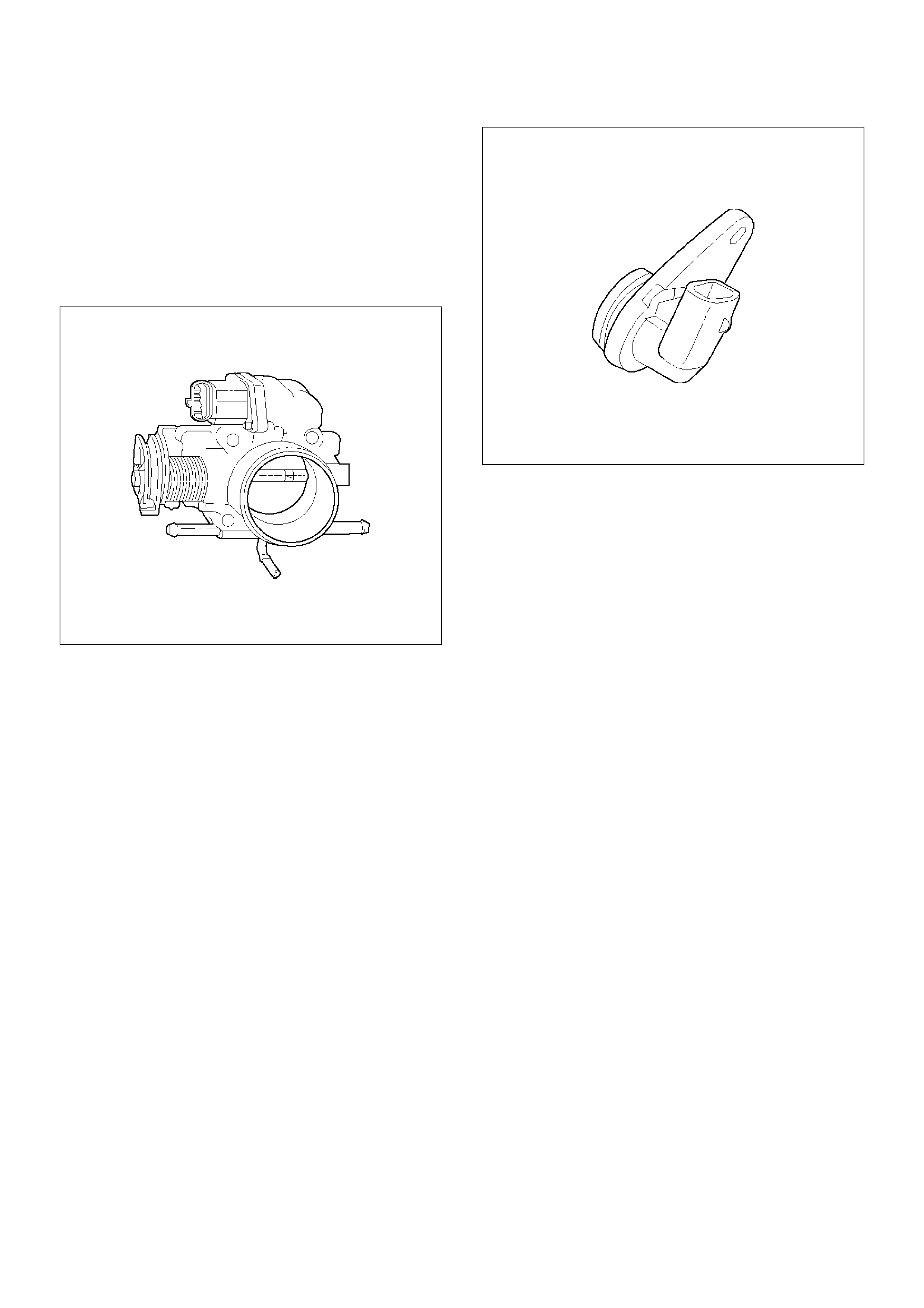
Throttle Body Unit
The throttle body has a throttle plate to control the
amount of air delivered to the engine. The TP sensor
and IAC valve are also mounted on the throttle body.
Vacuum ports located behind the throttle plate provide
the vacuum signals needed by various components.
Engine coolant is directed through a coolant cavity in
the throttle body to warm the throttle valve and to
prevent icing.
0019
General Description (Electronic Ignition
System)
Camshaft Position (CMP) Sensor
As the camshaft sprocket turns, a magnet in the
sprocket activates the Hall-effect switch in the CMP
sensor. When the Hall-effect switch is activated, it
grounds the signal line to the PCM, pulling the camshaft
position sensor signal circuit's applied voltage low. This
is a CMP signal. The CMP signals is created as piston
#1 is approximately 25° after top dead counter on the
power stroke. If the correct CMP signal is not received
by the PCM, DTC P0341 will be set.
0014
Crankshaft Position (CKP) Sensor
The crankshaft position (CKP) sensor provides a signal
used by the powertrain control module (PCM) to
calculate the ignition sequence. The sensor initiates
the 58X reference pulses which the PCM uses to
calculate RPM and crankshaft position.
Electronic Ignition
The electronic ignition system controls fuel combustion
by providing a spark to ignite the compressed air/fuel
mixture at the correct time. To provide optimum engine
performance, fuel economy, and control of exhaust
emissions, the PCM controls the spark advance of the
ignition system. Electronic ignition has the following
advantages over a mechanical distributor system:
• No moving parts.
• Less maintenance.
• Remote mounting capability.
• No mechanical load on the engine.
• More coil cooldown time between firing events.
• Elimination of mechanical timing adjustments.
• Increased available ignition coil saturation time.
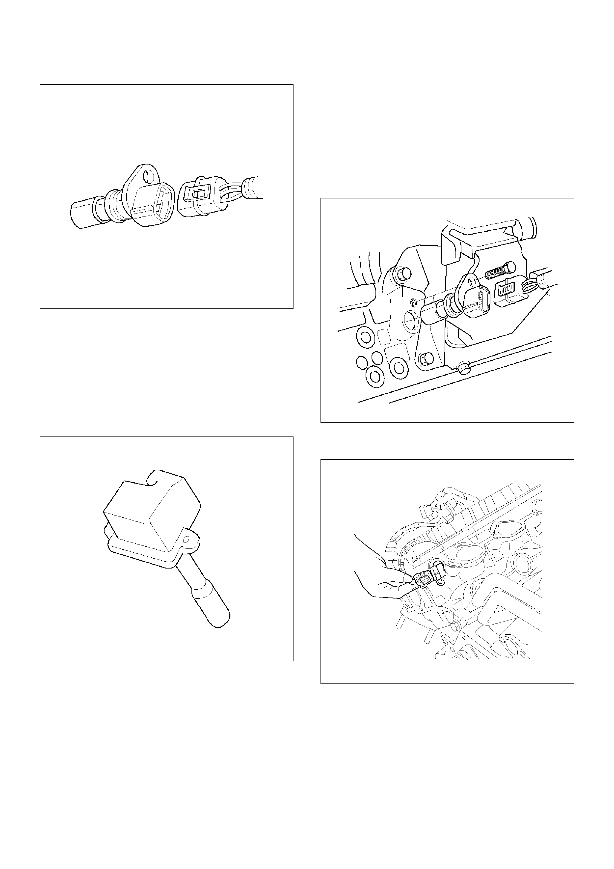
0013
Ignition Coils
A separate coil-at-plug module is located at each spark
plug. The coil-at-plug module is attached to the engine
with two screws. It is installed directly to the spark plug
by an electrical contact inside a rubber boot. A
three-way connector provides 12-volt primary supply
from the 15-amp ignition fuse, a ground-switching
trigger line from the PCM, and a ground.
0001
Ignition Control
The ignition control (IC) spark timing is the PCM's
method of controlling the spark advance and the ignition
dwell.
The IC spark advance and the ignition dwell are
calculated by the PCM using the following inputs:
• Engine speed.
• Crankshaft position (58X reference).
• Camshaft position (CMP) sensor.
• Engine coolant temperature (ECT) sensor.
• Throttle position (TP) sensor.
• Knock signal (knock sensor).
• Park/Neutral position (PRNDL input).
• Vehicle speed (vehicle speed sensor).
• PCM and ignition system supply voltage.
• The crankshaft positron (CKP) sensor sends the
PCM a 58X signal related to the exact position of the
crankshaft.
TS22909
• The camshaft position (CMP) sensor sends a signal
related to the position of the camshaft.
TS22910
• The knock sensor tells the PCM if there is any
problem with pre-ignition or detonation. This
information allows the PCM to retard timing, if
necessary.
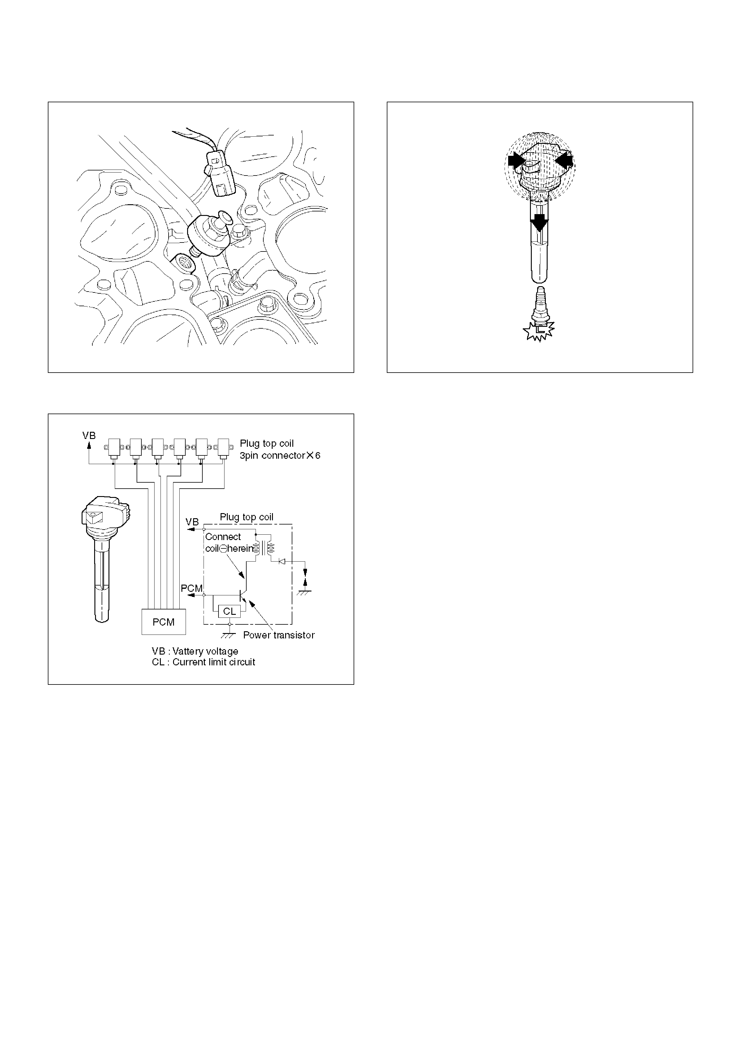
TS24037
Based on these sensor signals and engine load
information, the PCM sends 5V to each ignition coil.
060RW015
The PCM applies 5V signal voltage to the ignition coil
requiring ignition. This signal sets on the power
transistor of the ignition coil to establish a grounding
circuit for the primary coil, applying battery voltage to
the primary coil.
At the ignition timing, the PCM stops sending the 5V
signal voltage. Under this condition the power transistor
of the ignition coil is set off to cut the battery voltage to
the primary coil, thereby causing a magnetic field
generated in the primary coil to collapse. On this
moment a line of magnetic force flows to the secondary
coil, and when this magnetic line crosses the coil, high
voltage induced by the secondary ignition circuit to flow
through the spark plug to the ground.
TS24047
Ignition Control PCM Output
The PCM provides a zero volt (actually about 100 mV to
200 mV) or a 5-volt output signal to the ignition control
(IC) module. Each spark plug has its own primary and
secondary coil module ("coil-at-plug") located at the
spark plug itself. When the ignition coil receives the
5-volt signal from the PCM, it provides a ground path for
the B+ supply to the primary side of the coil-at -plug
module. This energizes the primary coil and creates a
magnetic field in the coil-at-plug module. When the
PCM shuts off the 5-volt signal to the ignition control
module, the ground path for the primary coil is broken.
The magnetic field collapses and induces a high voltage
secondary impulse which fires the spark plug and
ignites the air/fuel mixture.
The circuit between the PCM and the ignition coil is
monitored for open circuits, shorts to voltage, and shorts
to ground. If the PCM detects one of these events, it will
set one of the following DTCs:
• P0351: Ignition coil Fault on Cylinder #1
• P0352: Ignition coil Fault on Cylinder #2
• P0353: Ignition coil Fault on Cylinder #3
• P0354: Ignition coil Fault on Cylinder #4
• P0355: Ignition coil Fault on Cylinder #5
• P0356: Ignition coil Fault on Cylinder #6
Knock Sensor (KS) PCM Input
The knock sensor (KS) system is comprised of a knock
sensor and the PCM. The PCM monitors the KS
signals to determine when engine detonation occurs.
When a knock sensor detects detonation, the PCM
retards the spark timing to reduce detonation. Timing
may also be retarded because of excessive mechanical
engine or transmission noise.
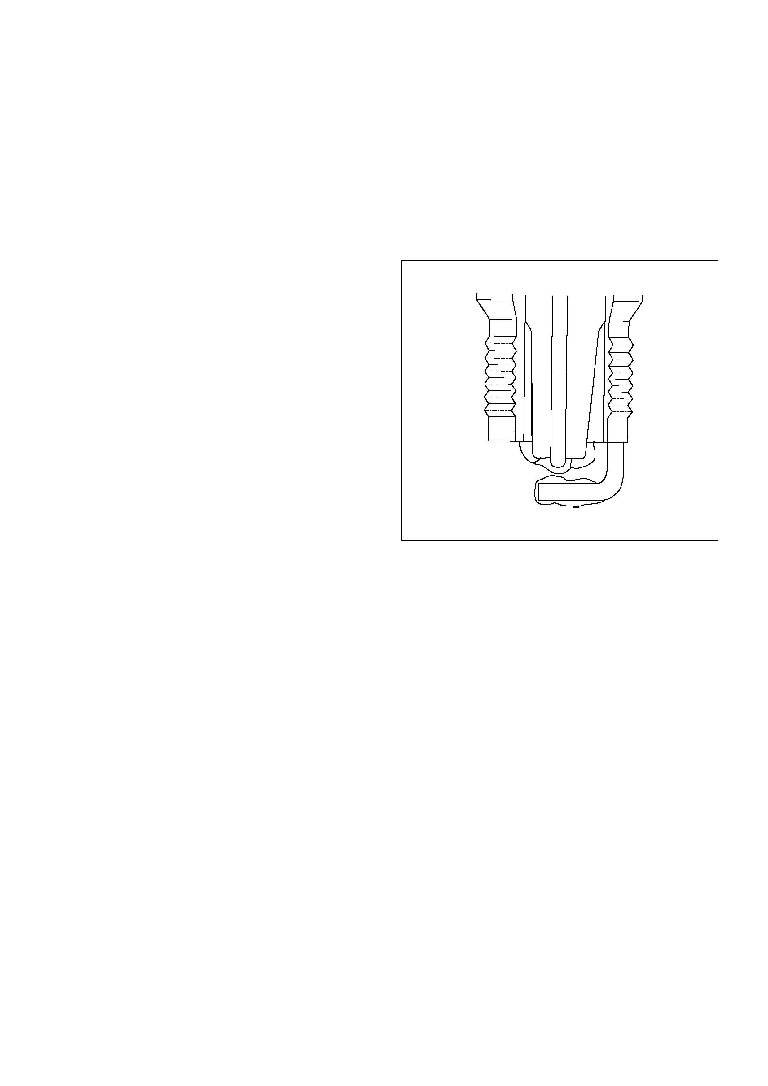
Powertrain Control Module (PCM)
The PCM is responsible for maintaining proper spark
and fuel injection timing for all driving conditions. To
provide optimum driveability and emissions, the PCM
monitors the input signals from the following
components in order to calculate spark timing:
•Engine coolant temperature (ECT) sensor.
•Intake air temperature (IAT) sensor.
•Mass air flow (MAF) sensor.
•PRNDL input from transmission range switch.
•Throttle position (TP) sensor.
•Vehicle speed sensor (VSS) .
•Crankshaft position (CKP) sensor.
Spark Plug
Although worn or dirty spark plugs may give satisfactory
operation at idling speed, they frequency fail at higher
engine speeds. Faulty spark plugs may cause poor fuel
economy, power loss, loss of speed, hard starting and
generally poor engine performance. Follow the
scheduled maintenance service recommendations to
ensure satisfactory spark plug performance. Refer to
Maintenance and Lubrication.
Normal spark plug operation will result in brown to
grayish-tan deposits appearing on the insulator portion
of the spark plug. A small amount of red-brown, yellow,
and white powdery material may also be present on the
insulator tip around the center electrode. These
deposits are normal combustion by-products of fuels
and lubricating oils with additives. Some electrode wear
will also occur. Engines which are not running properly
are often referred to as “misfiring.” This means the
ignition spark is not igniting the air/fuel mixture at the
proper time. While other ignition and fuel system
causes must also be considered, possible causes
include ignition system conditions which allow the spark
voltage to reach ground in some other manner than by
jumping across the air gap at the tip of the spark plug,
leaving the air/fuel mixture unburned. Misfiring may also
occur when the tip of the spark plug becomes
overheated and ignites the mixture before the spark
jumps. This is referred to as “pre-ignition.”
Spark plugs may also misfire due to fouling, excessive
gap, or a cracked or broken insulator. If misfiring occurs
before the recommended replacement interval, locate
and correct the cause.
Carbon fouling of the spark plug is indicated by dry,
black carbon (soot) deposits on the portion of the spark
plug in the cylinder. Excessive idling and slow speeds
under light engine loads can keep the spark plug
temperatures so low that these deposits are not burned
off. Very rich fuel mixtures or poor ignition system
output may also be the cause. Refer to DTC P0172.
Oil fouling of the spark plug is indicated by wet oily
deposits on the portion of the spark plug in the cylinder,
usually with little electrode wear. This may be caused
by oil during break-in of new or newly overhauled
engines. Deposit fouling of the spark plug occurs when
the normal red-brown, yellow or white deposits of
combustion by products become sufficient to cause
misfiring. In some cases, these deposits may melt and
form a shiny glaze on the insulator around the center
electrode. If the fouling is found in only one or two
cylinders, valve stem clearances or intake valve seals
may be allowing excess lubricating oil to enter the
cylinder, particularly if the deposits are heavier on the
side of the spark plug facing the intake valve.
TS23995
Excessive gap means that the air space between the
center and the side electrodes at the bottom of the
spark plug is too wide for consistent firing. This may be
due to improper gap adjustment or to excessive wear of
the electrode during use. A check of the gap size and
comparison to the gap specified for the vehicle in
Maintenance and Lubrication will tell if the gap is too
wide. A spark plug gap that is too small may cause an
unstable idle condition. Excessive gap wear can be an
indication of continuous operation at high speeds or
with engine loads, causing the spark to run too hot.
Another possible cause is an excessively lean fuel
mixture.
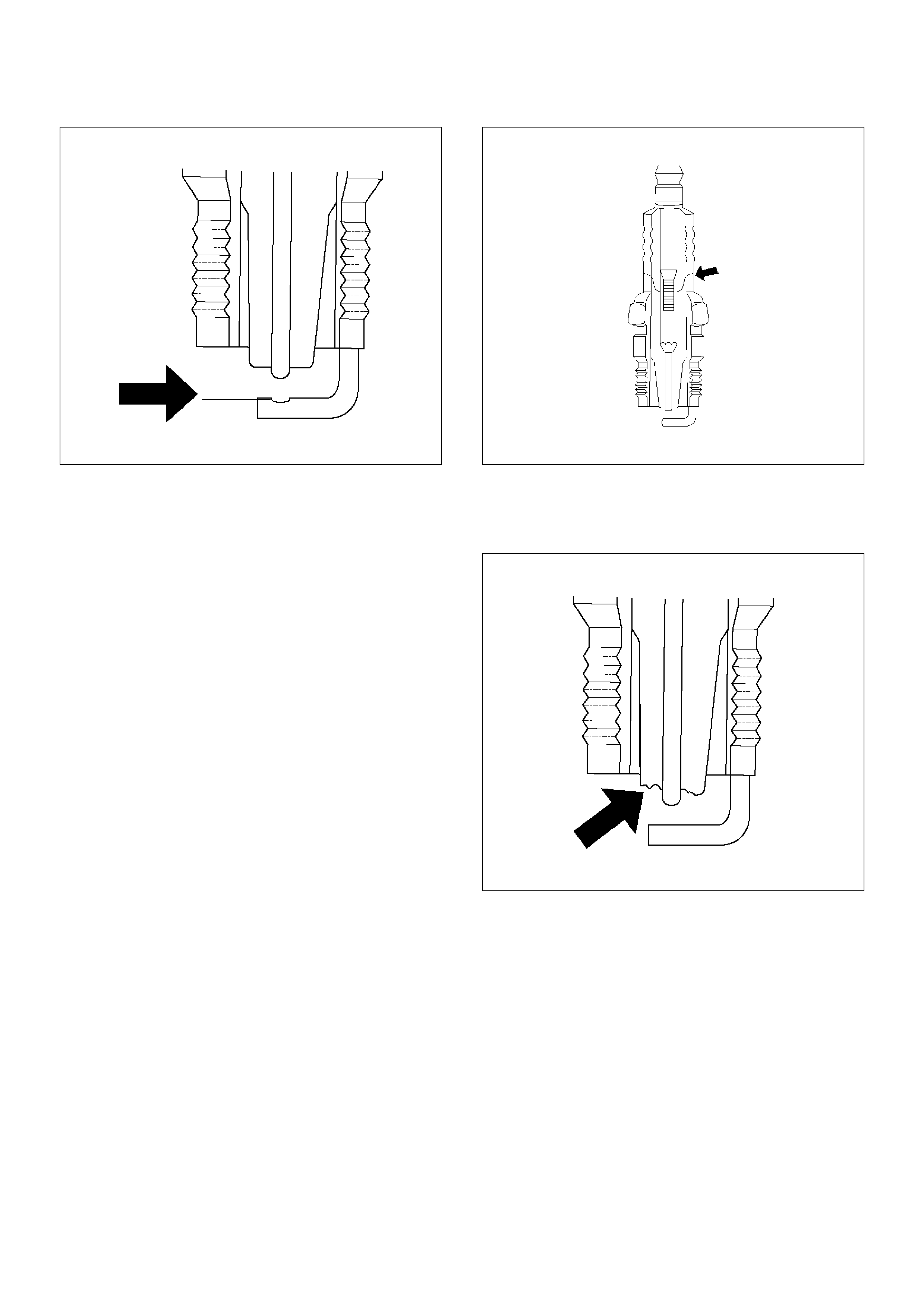
TS23992
Low or high spark plug installation torque or improper
seating can result in the spark plug running too hot and
can cause excessive center electrode wear. The plug
and the cylinder head seats must be in good contact for
proper heat transfer and spark plug cooling. Dirty or
damaged threads in the head or on the spark plug can
keep it from seating even though the proper torque is
applied. Once spark plugs are properly seated, tighten
them to the torque shown in the Specifications Table.
Low torque may result in poor contact of the seats due
to a loose spark plug. Overtightening may cause the
spark plug shell to be stretched and will result in poor
contact between the seats. In extreme cases, exhaust
blow-by and damage beyond simple gap wear may
occur.
Cracked or broken insulators may be the result of
improper installation, damage during spark plug
re-gapping, or heat shock to the insulator material.
Upper insulators can be broken when a poorly fitting
tool is used during installation or removal, when the
spark plug is hit from the outside, or is dropped on a
hard surface. Cracks in the upper insulator may be
inside the shell and not visible. Also, the breakage may
not cause problems until oil or moisture penetrates the
crack later.
TS23994
A broken or cracked lower insulator tip (around the
center electrode) may result from damage during
re-gapping or from “heat shock” (spark plug suddenly
operating too hot).
TS23993
• Damage during re-gapping can happen if the gapping
tool is pushed against the center electrode or the
insulator around it, causing the insulator to crack.
When re-gapping a spark plug, make the adjustment
by bending only the ground side terminal, keeping the
tool clear of other parts.
• "Heat shock" breakage in the lower insulator tip
generally occurs during several engine operating
conditions (high speeds or heavy loading) and may
be caused by over-advanced timing or low grade
fuels. Heat shock refers to a rapid increase in the tip
temperature that causes the insulator material to
crack.
Spark plugs with less than the recommended amount of
service can sometimes be cleaned and re-gapped ,
then returned to service. However, if there is any doubt
about the serviceability of a spark plug, replace it.
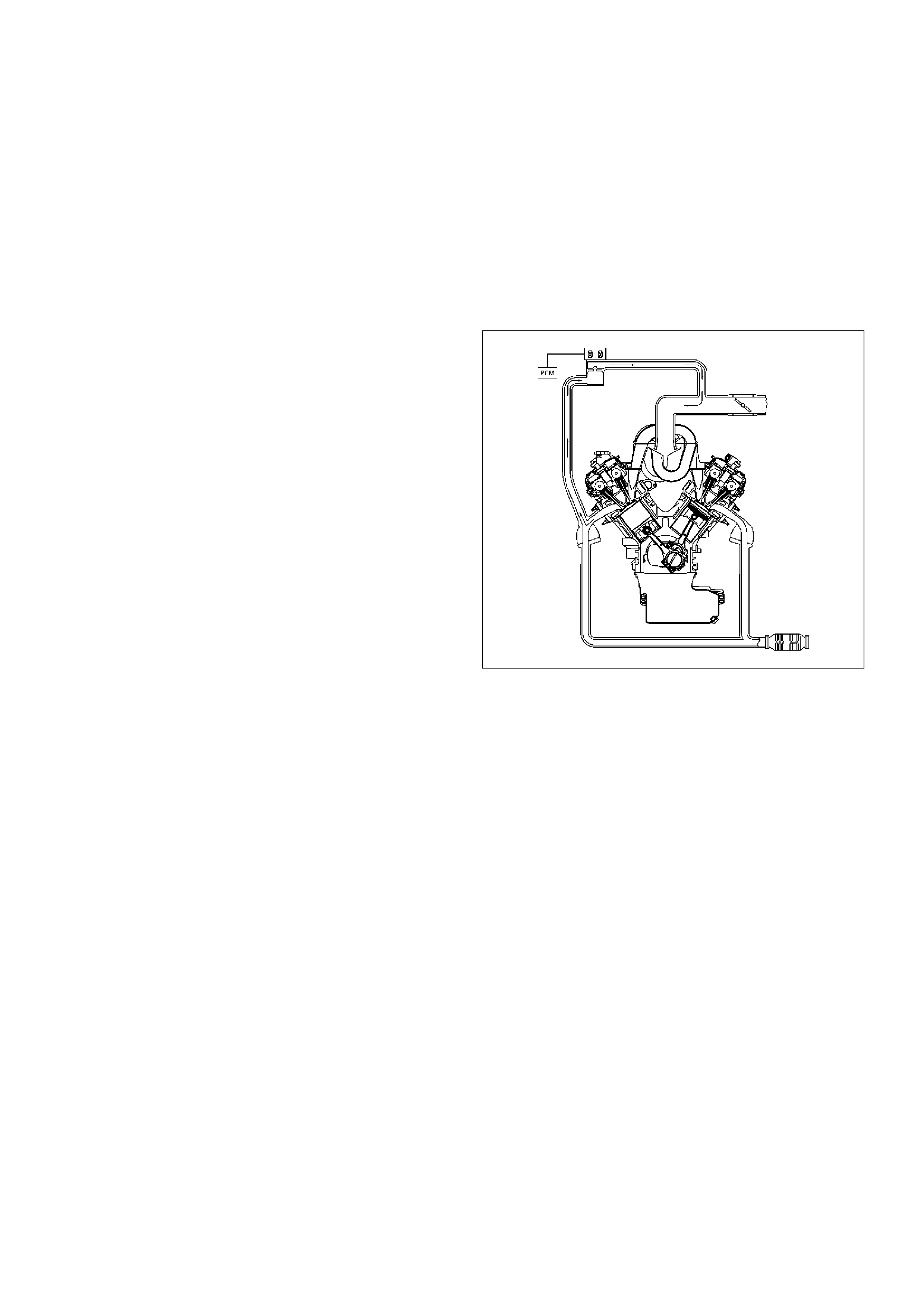
Spark plugs with cracked or broken insulators should
always be replaced.
A/C Clutch Diagnosis
A/C Clutch Circuit Operation
A 12-volt signal is supplied to the A/C request input of
the PCM when the A/C is selected through the A/C
control switch.
The A/C compressor clutch relay is controlled through
the PCM. This allows the PCM to modify the idle air
control position prior to the A/C clutch engagement for
better idle quality. If the engine operating conditions are
within their specified calibrated acceptable ranges, the
PCM will enable the A/C compressor relay. This is done
by providing a ground path for the A/C relay coil within
the PCM. When the A/C compressor relay is enabled,
battery voltage is supplied to the compressor clutch coil.
The PCM will enable the A/C compressor clutch
whenever the engine is running and the A/C has been
requested. The PCM will not enable the A/C
compressor clutch if any of the following conditions are
met:
•The throttle is greater than 90%.
•The engine speed is greater than 6315 RPM.
•The ECT is greater than 119°C (246°F).
•The IAT is less than 5°C (41°F).
•The throttle is more than 80% open.
A/C Clutch Circuit Purpose
The A/C compressor operation is controlled by the
powertrain control module (PCM) for the following
reasons:
•It improvises idle quality during compressor clutch
engagement.
•It improvises wide open throttle (WOT) performance.
•It provides A/C compressor protection from operation
with incorrect refrigerant pressures.
The A/C electrical system consists of the following
components:
•The A/C control head.
•The A/C refrigerant pressure switches.
•The A/C compressor clutch.
•The A/C compressor clutch relay.
•The PCM.
A/C Request Signal
This signal tells the PCM when the A/C mode is
selected at the A/C control head. The PCM uses this to
adjust the idle speed before turning on the A/C clutch.
The A/C compressor will be inoperative if this signal is
not available to the PCM.
Refer to A/C Clutch Circuit Diagnosis for A/C wiring
diagrams and diagnosis for A/C electrical system.
General Description (Exhaust Gas
Recirculation (EGR) System)
EGR Purpose
The exhaust gas recirculation (EGR) system is use to
reduce emission levels of oxides of nitrogen (NOx).
NOx emission levels are caused by a high combustion
temperature. The EGR system lowers the NOx
emission levels by decreasing the combustion
temperature.
057RW002
Linear EGR Valve
The main element of the system is the linear EGR
valve. The EGR valve feeds small amounts of exhaust
gas back into the combustion chamber. The fuel/air
mixture will be diluted and combustion temperatures
reduced.
Linear EGR Control
The PCM monitors the EGR actual positron and adjusts
the pintle position accordingly. The uses information
from the following sensors to control the pintle position:
• Engine coolant temperature (ECT) sensor.
• Throttle position (TP) sensor.
• Mass air flow (MAF) sensor.
Linear EGR Valve Operation and Results of
Incorrect Operation
The linear EGR valve is designed to accurately supply
EGR to the engine independent of intake manifold
vacuum. The valve controls EGR flow from the exhaust
to the intake manifold through an orifice with a PCM
controlled pintle. During operation, the PCM controls
pintle position by monitoring the pintle position feedback
signal. The feedback signal can be monitored with
Tech 2 as “Actual EGR Pos.” “Actual EGR Pos.”should
always be near the commanded EGR position ("Desired
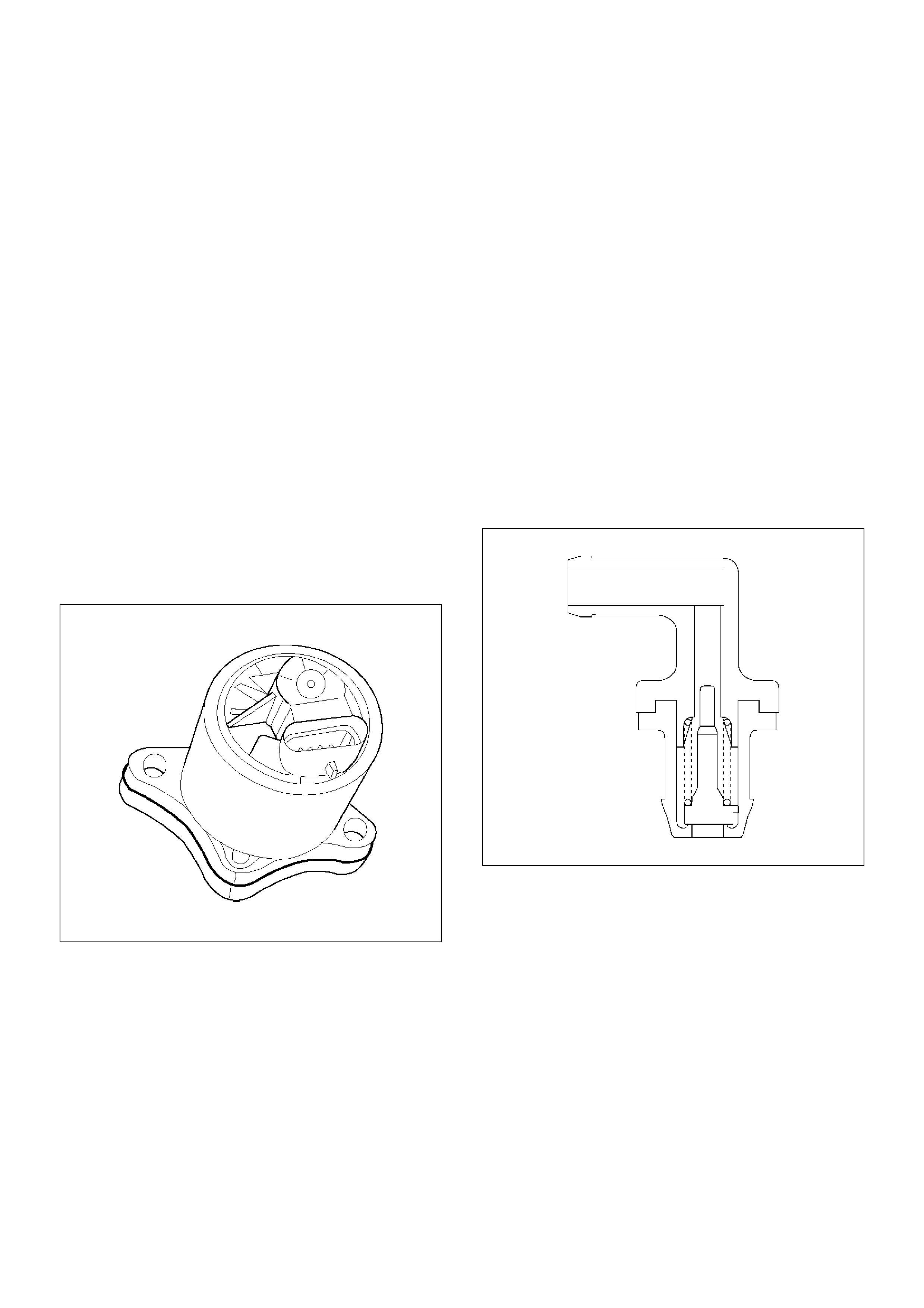
EGR Pos."). If a problem with the EGR system will not
allow the PCM to control the pintle position properly,
DTC P1406 will set. The PCM also tests for EGR flow.
If incorrect flow is detected, DTC P0401 will set. If
DTCs P0401 and/or P1406 are set, refer to the DTC
charts.
The linear EGR valve is usually activated under the
following conditions:
• Warm engine operation.
• Above-idle speed.
Too much EGR flow at idle, cruise or cold operation may
cause any of the following conditions to occur:
• Engine stalls after a cold start.
• Engine stalls at idle after deceleration.
• Vehicle surges during cruise.
• Rough idle.
Too little or no EGR flow may allow combustion
temperatures to get too high. This could cause:
• Spark knock (detonation).
• Engine overheating.
• Emission test failure.
• DTC P0401 (EGR flow test).
• Poor fuel economy.
0017
EGR Pintle Position Sensor
The PCM monitors the EGR valve pintle position input
to endure that the valve responds properly to
commands from the PCM and to detect a fault if the
pintle position sensor and control circuits are open or
shorted. If the PCM detects a pintle position signal
voltage outside the normal range of the pintle position
sensor, or a signal voltage that is not within a tolerance
considered acceptable for proper EGR system
operation, the PCM will set DTC P1406.
General Description (Positive Crankcase
Ventilation (PCV) System)
Crankcase Ventilation System Purpose
The crankcase ventilation system is use to consume
crankcase vapors in the combustion process instead of
venting them to the atmosphere. Fresh air from the
throttle body is supplied to the crankcase and mixed
with blow-by gases. This mixture is then passed
through the positive crankcase ventilation (PCV) valve
into the common chamber.
Crankcase Ventilation System Operation
The primary control is through the positive crankcase
ventilation (PCV) valve. The PCV valve meters the flow
at a rate that depends on the intake vacuum. The PCV
valve restricts the flow when the inlet vacuum is highest.
In addition, the PCV valve can seal the common
chamber off in case of sudden high pressure in the
crankcase.
028RV002
While the engine is running, exhaust fuses and small
amounts of the fuel/air mixture escape past the piston
rings and enter the crankcase. These gases are mixed
with clean air entering through a tube from the air intake
duct.
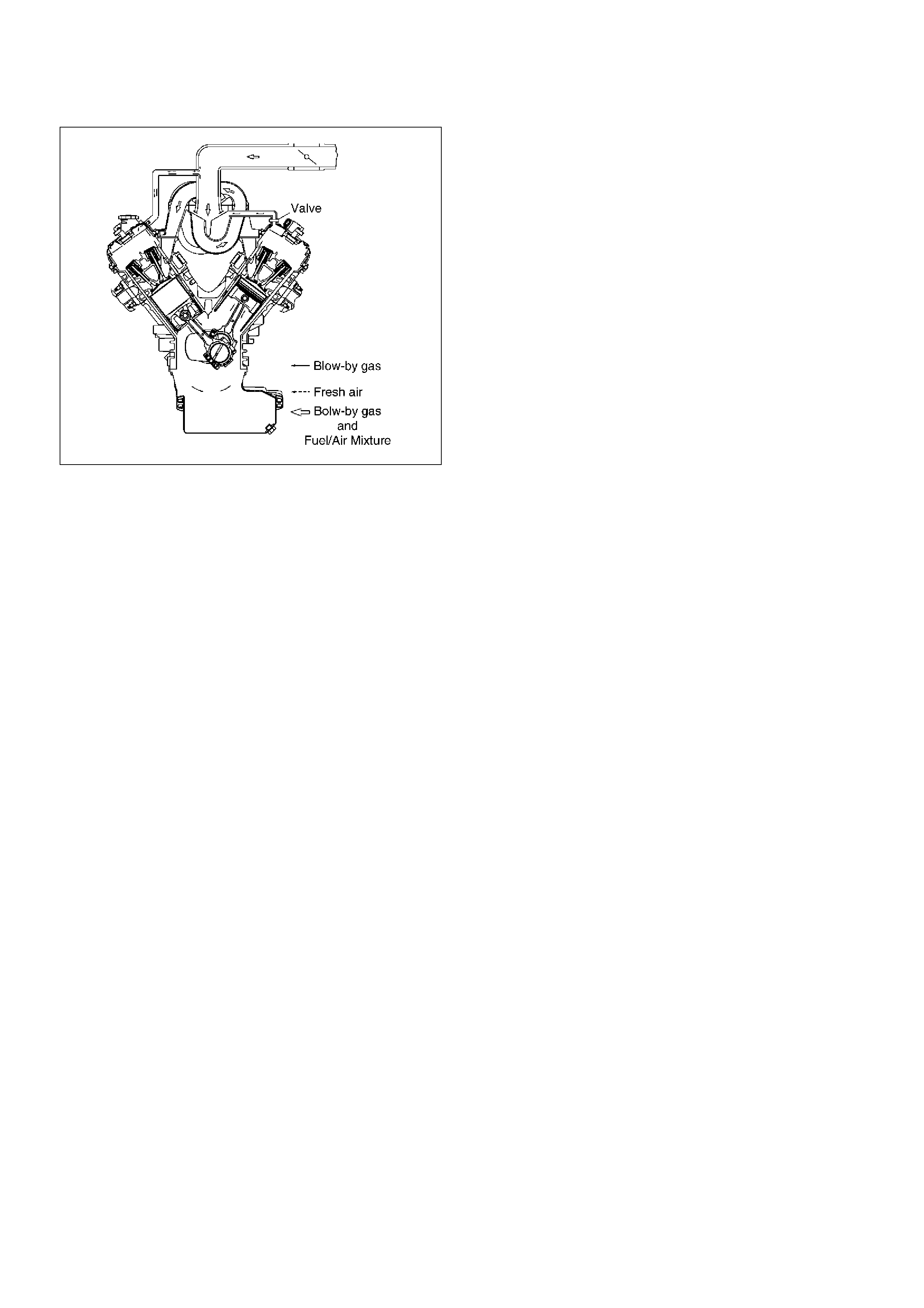
028RW002
During normal, part-throttle operation, the system is
designed to allow crankcase gases to flow through the
PCV valve into the throttle body to be consumed by
normal combustion.
A plugged valve or PCV hose may cause the following
conditions:
• Rough idle.
• Stalling of slow idle speed.
• Oil leaks.
• Sludge in the engine.
A leaking PCV hose would cause:
• Rough idle.
• Stalling.
• High idle speed.
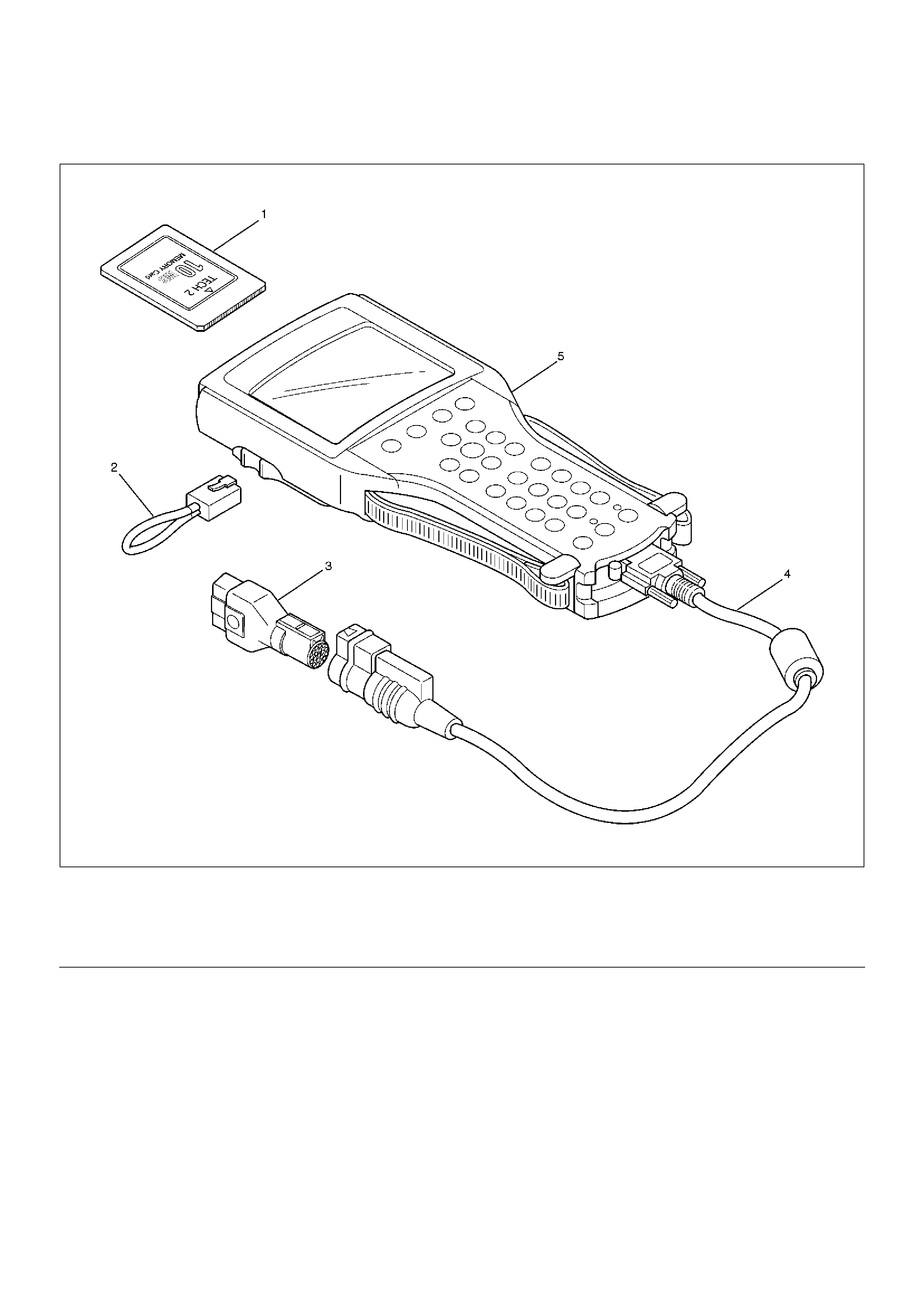
Special Tools
901RW180
EndOFCallout
Legend
(1) PCMCIA Card
(2) RS232 Loop Back Connector
(3) SAE 16/19 Adapter
(4) DLC Cable
(5) TECH–2
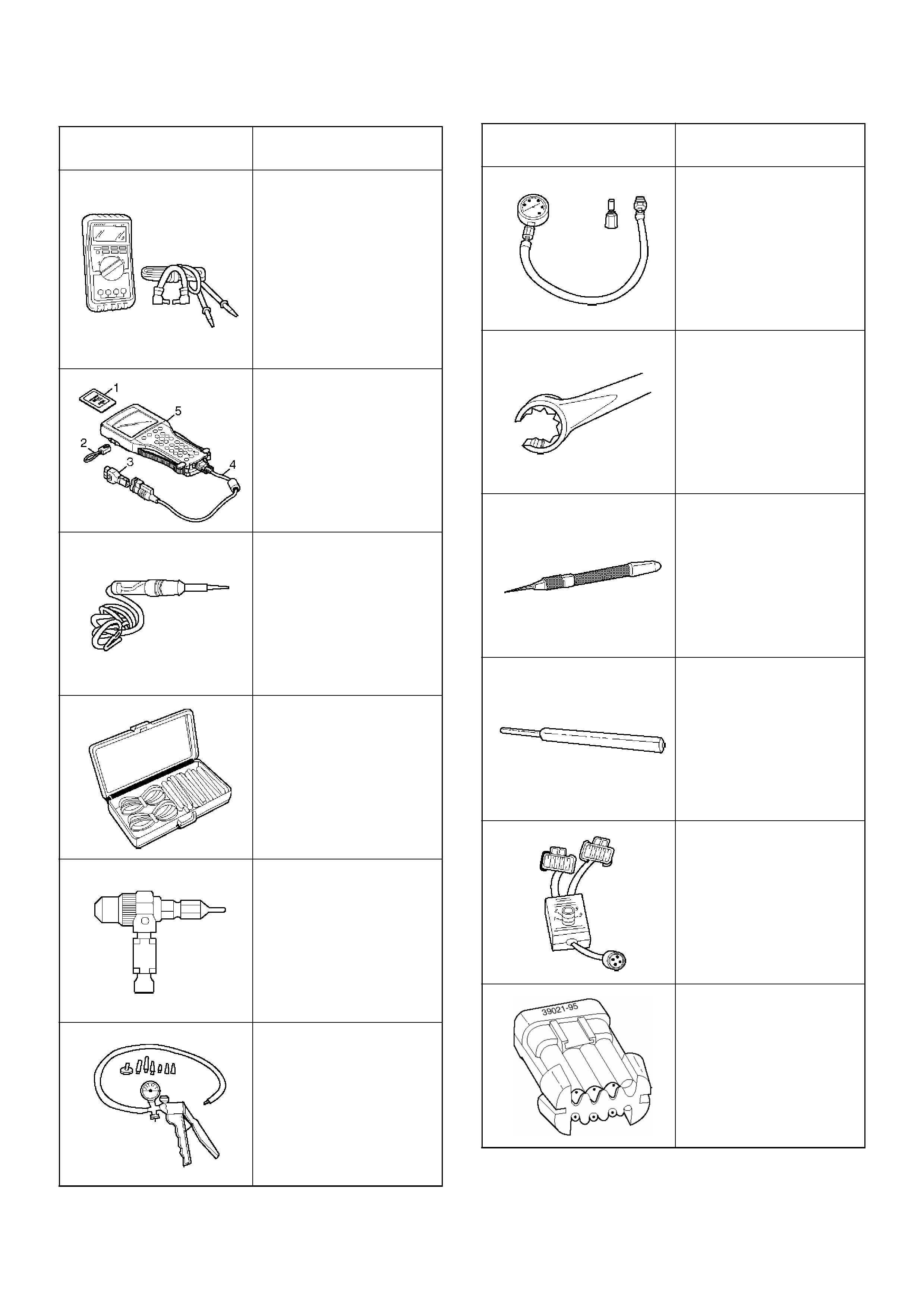
ILLUSTRATION TOOL NO.
TOOL NAME
5-8840-0285-0
(J 39200)
High Impedance
Multimeter (Digital
Voltmeter – DVM)
(1) PCMCIA Card
(2) RS232 Loop Back
Connector
(3) SAE 16/19 Adapter
(4) DLC Cable
(5) TECH–2
5-8840-0607-0
(J 34142-B)
Unpowered Test Light
5-8840-0385-0
(J 35616-A/BT-8637)
Connector Test Adapter
Kit
5-8840-0383-0
(J 26792/BT-7220-1)
Spark Tester
5-8840-0279-0
(J 23738-A)
Vacuum Pump with
Gauge or common tool
BT-8515
Exhaust Back Pressure
Tester or common tool
5-8840-2640-0
(J 39194-B)
Heated Oxygen Sensor
Wrench
5-8840-0632-0
(J 35689-A)
Terminal Remover
5-8840-0388-0
(J 28742-A)
Weather Pack II Terminal
Remover
5-8840-2635-0
(J 39021-90)
Injector Switch Box
5-8840-2636-0
(J 39021-65)
Injector Test Light
ILLUSTRATION TOOL NO.
TOOL NAME
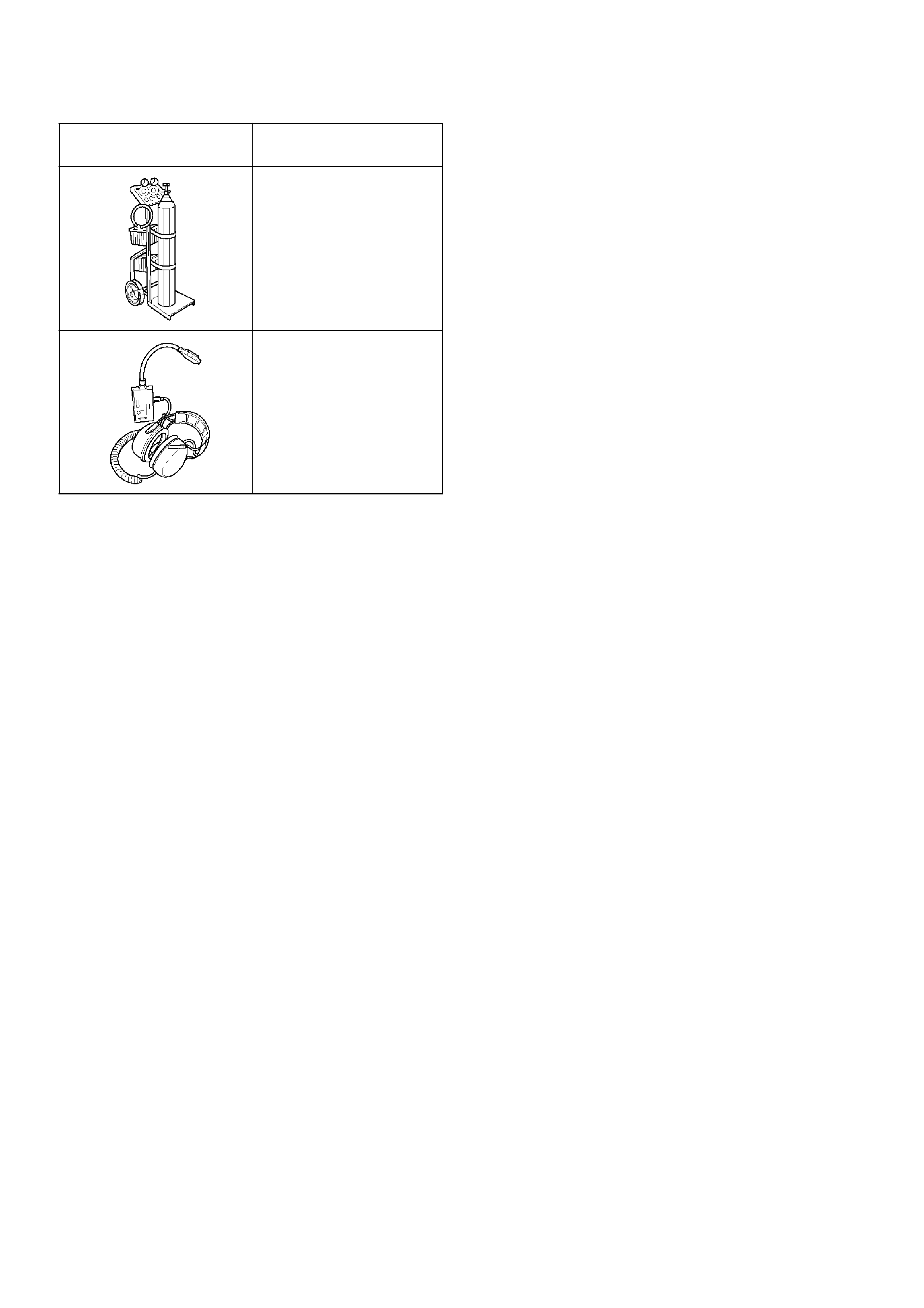
1. 5-8840-2607-0 (J-41413)EVAP Pressure/Purge
Diagnostic Station is a multipurpose tool which is
used to perform several diagnostic procedures for
enhanced emission testing. The station will
accommodate a nitrogen gas filled cylinder which is
used to pressurize the vehicle EVAP system for a
leakdown test and leak location test when a vehicle
is repaired for leakage in the enhanced evaporative
emission control system. It also has two additional
gauges (inches of mercury and inches of water)
which are used to measure both source vacuum
and EVAP canister purge vacuum to verify correct
operation and vapor flow within the canister purge
circuit.
2. 5-8840-2608-0 (J-41416) Ultrasonic Leak Detector
is a microprocessor-based device used to detect
leaks in the enhanced evaporative emission control
system. The evaporative system is pressurized to
30 inches of water using the 5-8840-2607-0
(J-41413) EVAP Pressure/Purge Diagnostic
System. Small leaks in the EVAP system will emit
sound at a high frequency undetectable by a human
ear but detectable with the 5-8840-2608-0
(J-41416). The technician traces along the
evaporative system and can pinpoint leaks due to
corroded lines, cracked hoses, or a damaged EVAP
component. The detector includes a high quality
set of headphones to block out surrounding shop
noise and the LED sensitivity meter allows a visual
reference for locating leaks in conjunction with the
audio output heard through the headphones.
Powered by (1) nine volt battery.
5-8840-2607-0
(J 41413)
EVAP Pressure/Purge
Diagnostic Station
5-8840-2608-0
(J 41416)
Ultrasonic Leak Detector
ILLUSTRATION TOOL NO.
TOOL NAME