
SECTION 7A1 - CLUTCH (6VE1 ENGINE)
Service Precaution
General Description
Diagnosis
Clutch Assembly
Clutch Assembly and Associated Parts
Removal
Inspection and Repair
Installation
Clutch Control
Clutch Control Parts
Removal
Inspection and Repair
Installation
Adjustment
Master Cylinder
Disassembled View
Disassembly
Inspection and Repair
Reassembly
Slave Cylinder
Disassembled View
Disassembly
Inspection and Repair
Reassembly
Damper Cylinder
Disassembled View
Disassembly
Inspection and Repair
Reassembly
Main Data and Specifications
General Specifications
Torque Specifications
Special Tools
Service Precaution
WARNING: IF SO EQUIPPED WITH A
SUPPLEMENTAL RESTRAINT SYSTEM (SRS),
REFER TO THE SRS COMPONENT AND WIRING
LOCATION VIEW IN ORDER TO DETERMINE
WHETHER YOU ARE PERFORMING SERVICE ON
OR NEAR THE SRS COMPONENTS OR THE SRS
WIRING. WHEN YOU ARE PERFOMING SERVICE ON
OR NEAR THE SRS COMPONENTS OR THE SRS
WIRING, REFER TO THE SRS SERVICE
INFORMATION. FAILURE TO FOLLOW WARNINGS
COULD RESULT IN POSSIBLE AIR BAG
DEPLOYMENT, PERSONAL INJURY, OR
OTHERWISE UNNEEDED SRS SYSTEM REPAIRS.
CAUTION: Always use the correct fastener in the
proper location. When you replace a fastener, use
ONLY the exact part number for that application.
HOLDEN will call out those fasteners that require a
replacement after removal. HOLDEN will also call
out the fasteners that require thread lockers or
thread sealant. UNLESS OTHERWISE SPECIFIED ,
do not use supplemental coatings (Paints, greases,
or other corrosion inhibitors) on threaded fasteners
or fastener joint interfaces. Generally, such
coatings adversely affect the fastener torque and
the joint clamping force, and may damage the
fastener. When you install fasteners, use the correct
tightening sequence and specifications. Following
these instructions can help you avoid damage to
parts and systems.
General Description
Clutch
6VE1
A07RW046
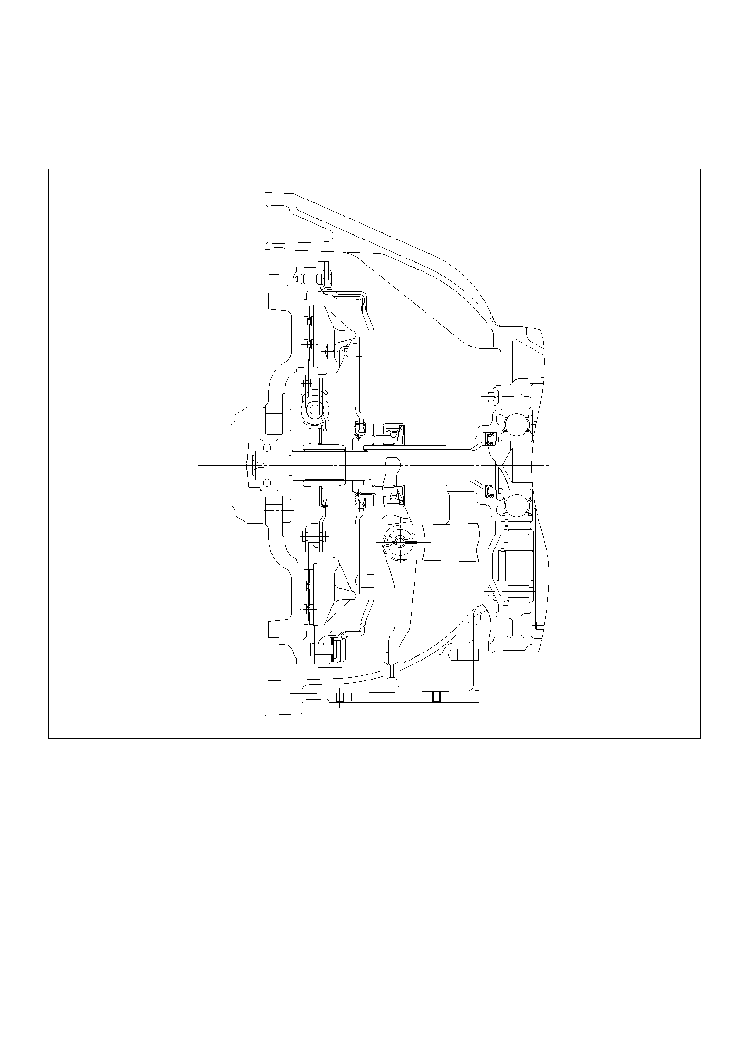
For 6VE1 (3.5L) engine models, the pull-type clutch is
employed. The pull-type clutch is disengaged by
pulling the release lever (release bearing) to disengage
the pressure plate.
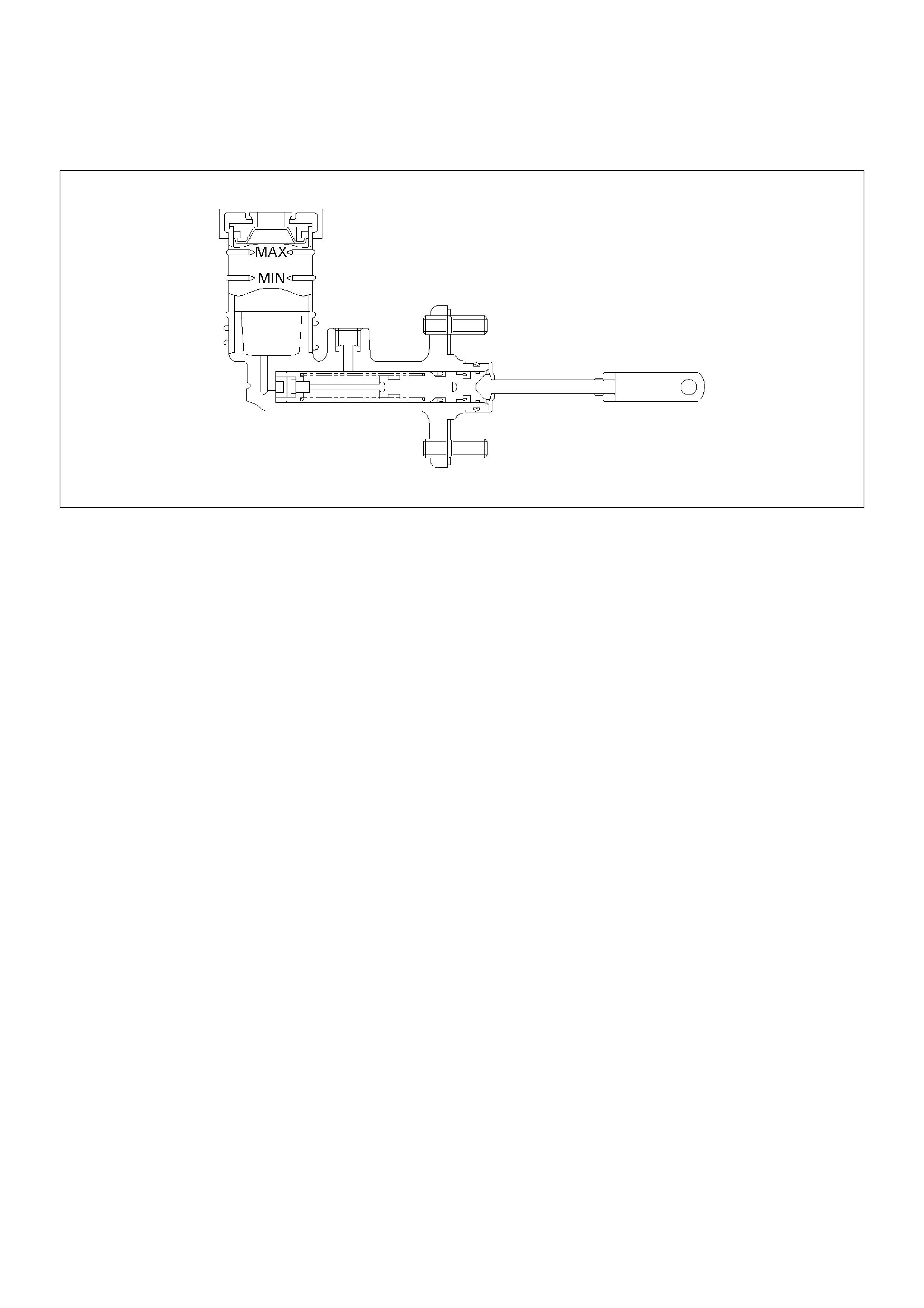
Master Cylinder
6VE1
A07RW066
A07RW067
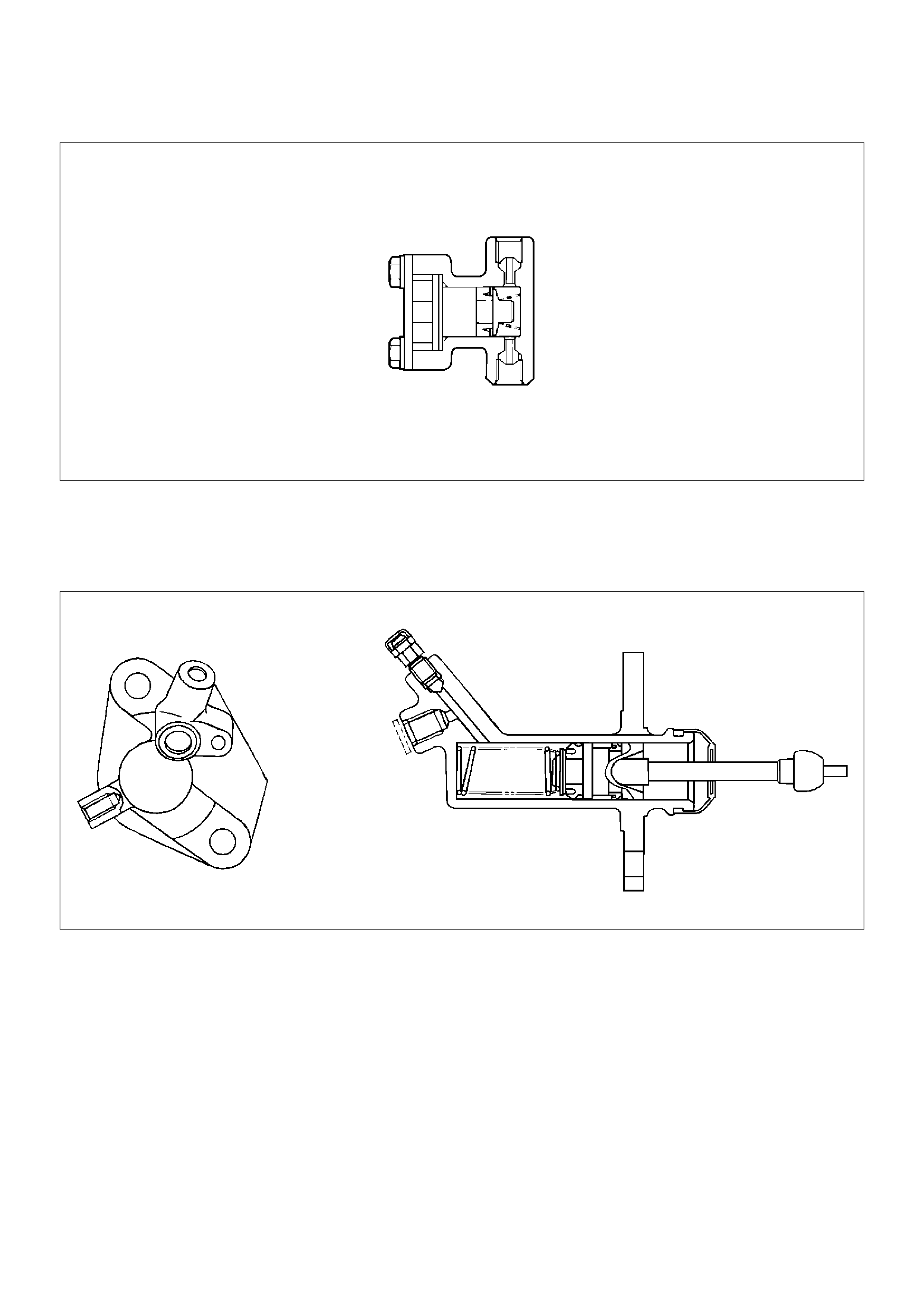
Damper Cylinder
A07RS004
In order to improve the operation of the clutch hydraulic system, a damper cylinder is used in the hydraulic line
between the master cylinder and the slave cylinder.
Slave Cylinder
A07RS005
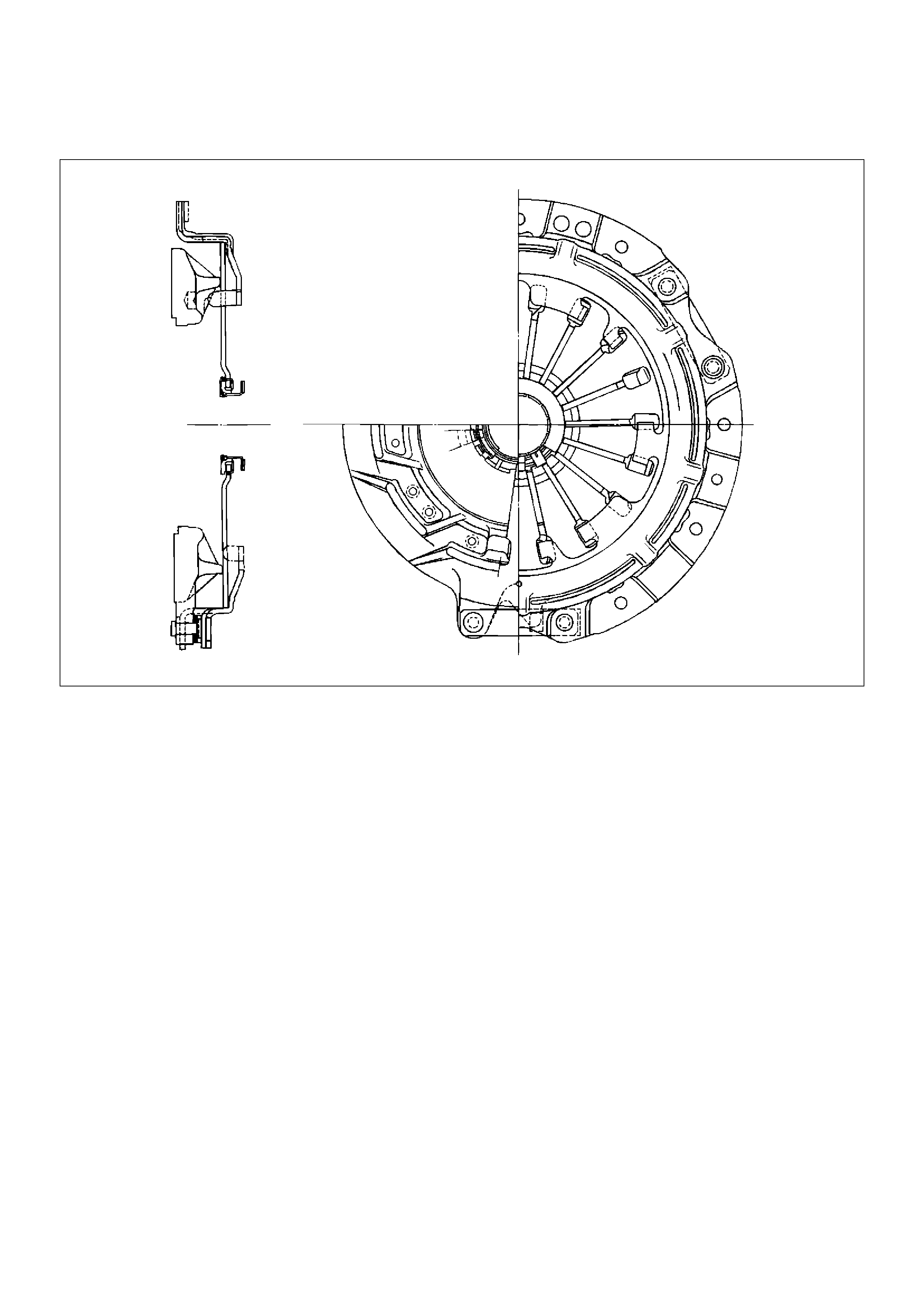
Pressure Plate Assembly
A07RS006
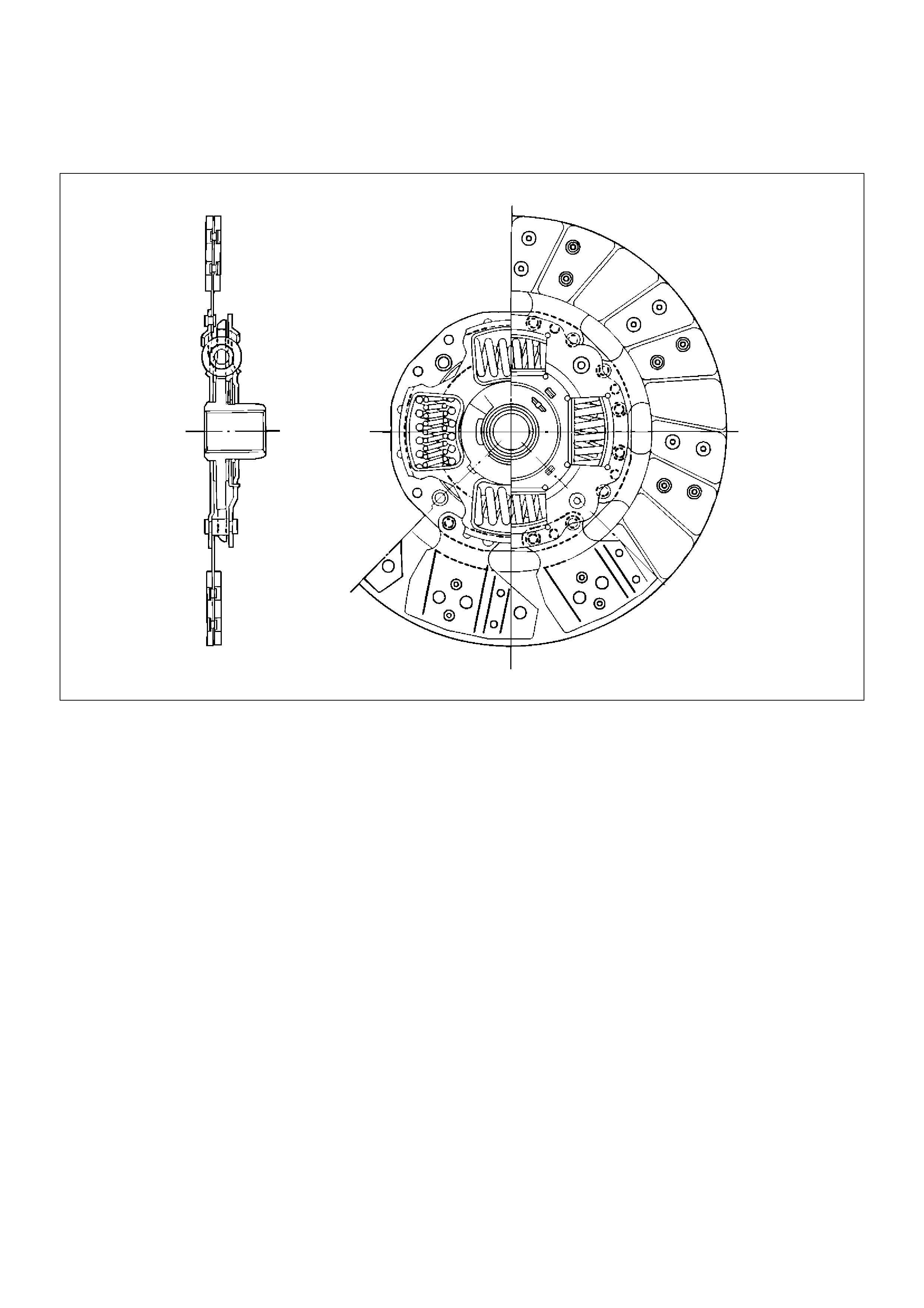
Driven Plate Assembly
A07RS007
Diagnosis
Condition Possible Cause Correction
Dragging Fluid leakage. Repair
Air in hydraulic line. Bleed
Master cylinder and slave cylinder
seals worn.
Replace master cylinder.
Replace slave cylinder seals.
Driven plate warped. Replace driven plate.
Diaphragm spring weakened or tip of
fingers worn.
Replace pressure plate
Driven plate sticking on splines. Lubricate with grease or replace.
Clutch spline worn. Repair
Release bearing worn or damaged. Replace release bearing.
Slipping Driven plate facing worn or oil–
soaked.
Replace driven plate and check for
leaks.
Diaphragm spring weakened. Replace pressure plate.
Pressure plate or flywheel warped. Correct or replace.
Master cylinder and slave cylinder
seals worn.
Replace master cylinder.
Replace slave cylinder seals.
Chattering Engine mounts loose or damaged. Tighten or replace.
Driven plate facing warped. Replace driven plate.
Surface of facing hardened. Replace driven plate
Driven plate facing oil soaked. Replace driven plate and check for
leaks.
Damper springs weakened or
broken.
Replace.
Pressure plate or flywheel warped. Correct or replace.
Noisy Replace bearing binding. Correct, or replace if damaged, and
lubricate.
Replace bearing worn or damaged. Replace release bearing.
Release bearing poorly lubricated. Lubricate.
Pilot bearing worn. Replace pilot bearing.
Damper springs weakened or
broken.
Replace driven plate.
Rivets of driven plate exposed. Replace driven plate.
Replace driven plate. Hydraulic line blocked. Clean out or replace.
Master or slave cylinders binding. Repair or replace as needed.
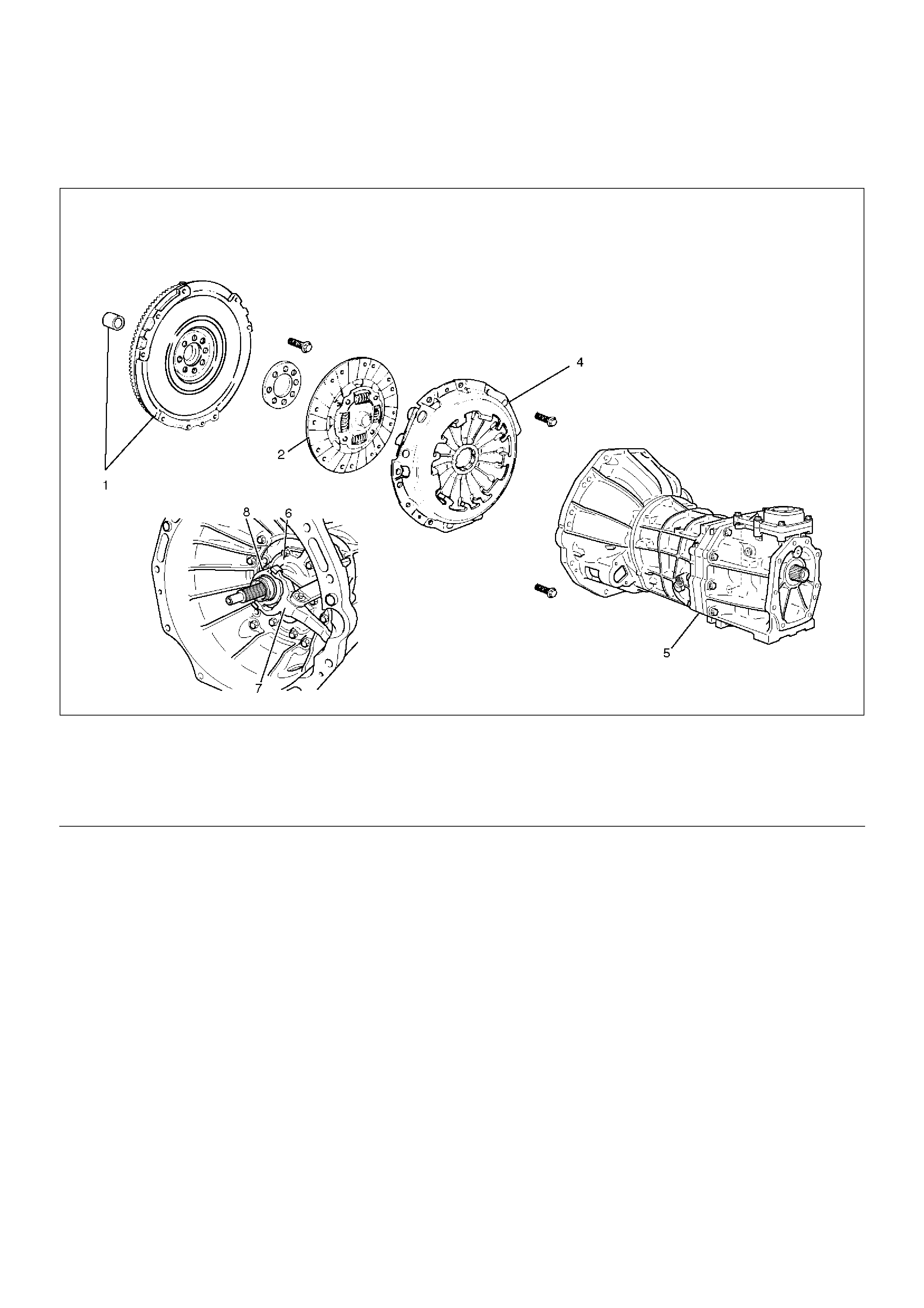
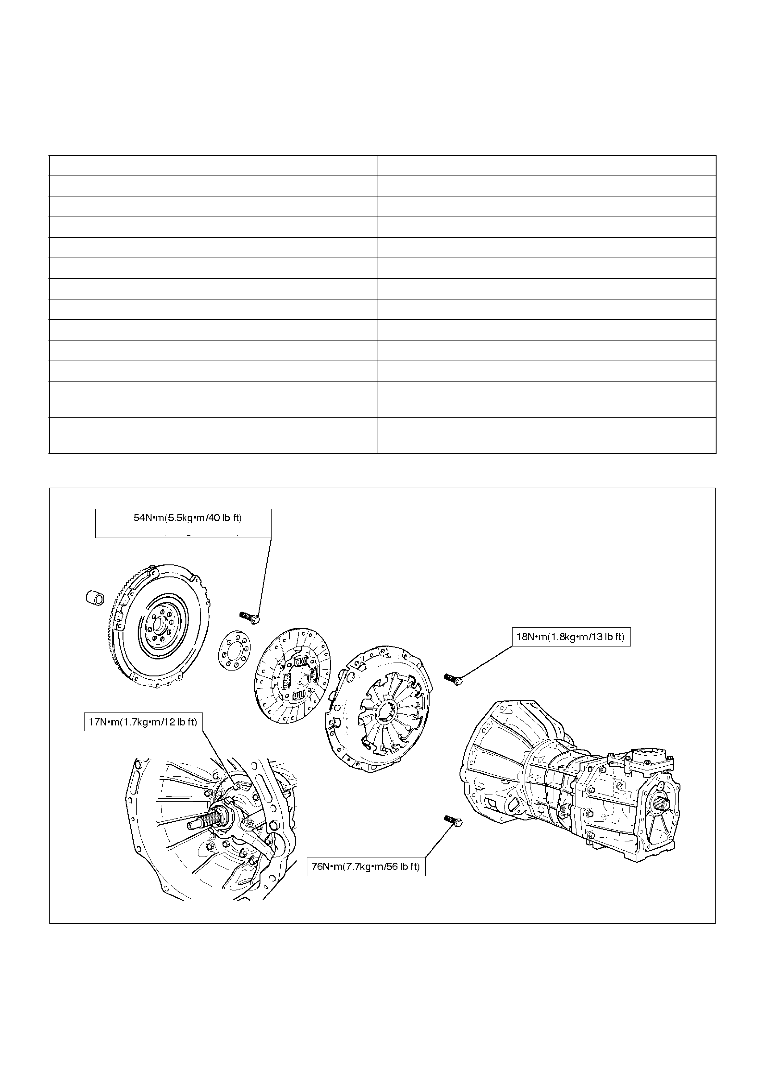
Clutch Assembly
Clutch Assembly and Associated Parts
201RW029
EndOFCallout
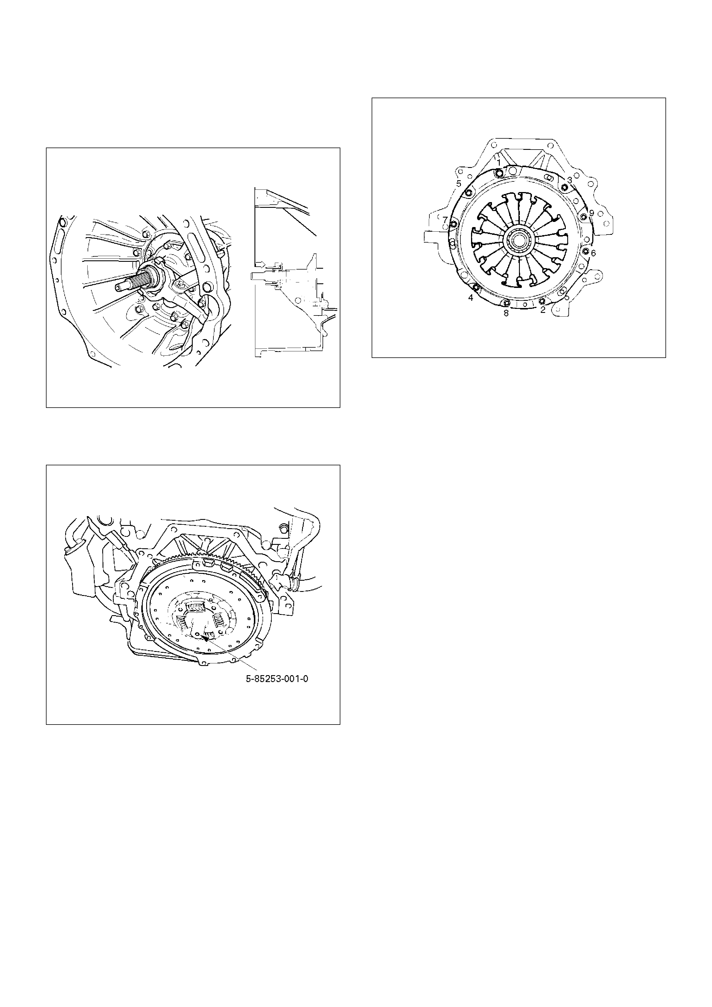
Removal
1.Remove transmission assembly, refer to "MANUAL
TRANSMISSION" of Section 7B for "Removal AND
INSTALLATION" procedure.
2. Mark the flywheel, clutch cover and pressure plate
lug for alignment when installing.
3. Remove pressure plate assembly (3).
Legend
(1) Flywheel Assembly and Crankshaft Bearing
(2) Driven Plate Assembly
(4) Pressure Plate Assembly
(5) Transmission Assembly
(6) Front Cover
(7) Shift Fork
(8) Release Bearing
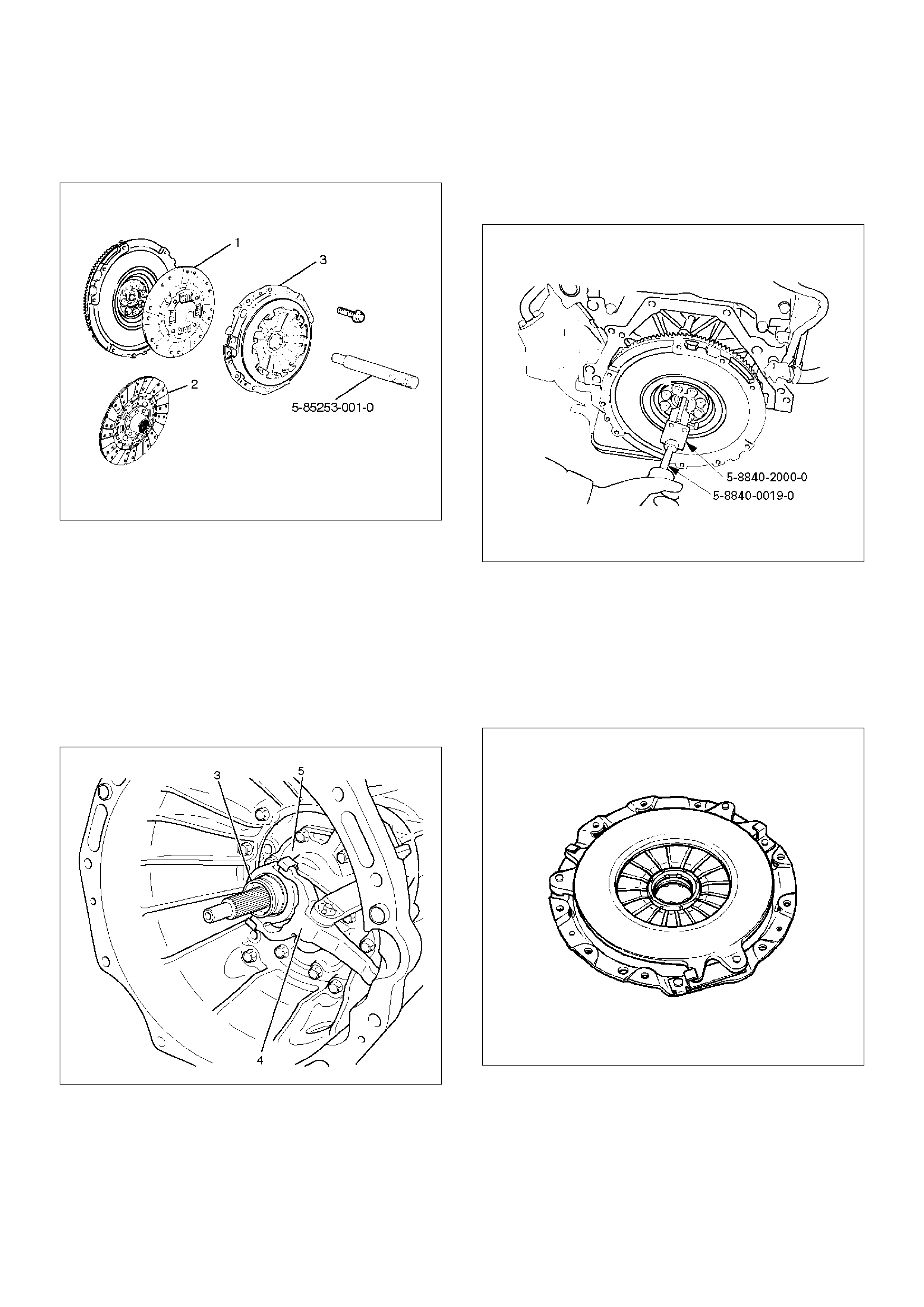
4. Remove driven plate assembly (1) or (2). Use the
pilot aligner 5-85253-001-0 (J-24547) to prevent the
driven plate assembly from falling free.
201RW031
5. Mark the flywheel, clutch cover and pressure plate
lug for alignment when installing.
6. Remove the release bearing (3) from the
transmission case .
7. Remove the shift fork snap pin.
8. Remove the shift fork pin and shift fork (4) from the
front cover.
9. Remove the front cover bolts.
10. Remove the front cover (5) from the transmission
case.
220RW088
11. Remove flywheel assembly and crankshaft bearing.
Do not remove except for replacement.
12. Use the remover 5–8840–2000–0 (J–5822) and
sliding hammer 5–8840–0019–0 (J–23907) to
remove the crankshaft bearing
015RW053
Inspection and Repair
Make necessary correction or parts replacement if wear,
damage, or any other abnormal condition are found
through inspection.
Pressure Plate Assembly
201RS002
1. Visually check the pressure plate friction surface for
excessive wear and heat cracks.
2. If excessive wear or deep heat cracks are present,
the pressure plate must be replaced.
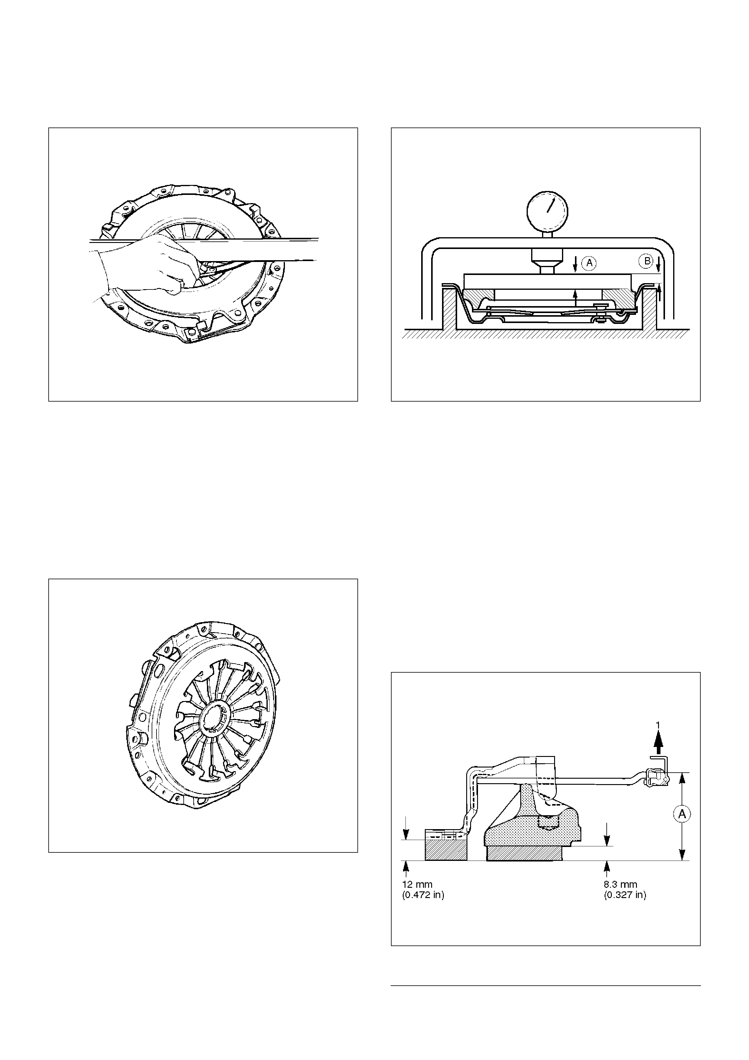
Pressure Plate Warpage
201RS003
1. Use a straight edge and a feeler gauge to measure
the pressure plate friction surface flatness in four
directions.
2. If any of the measured values exceeds the specified
limit, the pressure plate must be replaced.
Pressure Plate Warpage
Limit: 0.3mm (0.012in)
Clutch Cover
201RS004
1. Visually check the entire clutch cover for excessive
wear, cracking, and other damage.
2. The clutch cover must be replaced if any of these
conditions are present.
Clutch Set Force
201RS005
1. Invert the pressure plate assembly.
2. Place a new driven plate over the pressure plate. A
metal sheet with “A” thickness of 8.3mm (0.327in)
may be used in place of the driven plate.
3. Compress the pressure plate assembly until the
distance “B” becomes 12mm (0.472 in).
4. Note the pressure gauge reading.
5. If the measured value is less than the specified limit,
the pressure plate assembly must be replaced.
Clutch Set Force
Standard: 7208N ( 1621lb)
Limit: 6468N (1454 lb)
Diaphragm Spring Finger Height
201RW009
EndOFC allout
1. Place a new driven plate or a 8.3mm (0.327in)
Legend
(1) Release Side
spacer beneath the pressure plate.
2. Fully compress the pressure plate and diaphragm
spring.
3. There are two ways to do this.
4. Use a bench press to press down on the assembly
from the top.
5. Tighten the fixing bolts.
NOTE: Preload on diaphragm spring finger must be 49
– 98 N (11 – 22lb) in direction of release, when clutch
cover assembly is bolted to the flywheel.
6. Measure the spring height from base to spring
tip“A”. If the measured value exceeds the specified
limit, the pressure plate assembly must be replaced.
Diaphragm Spring Finger Height
Standard: 49.9mm – 51.9mm (1.965in – 2.043 in)
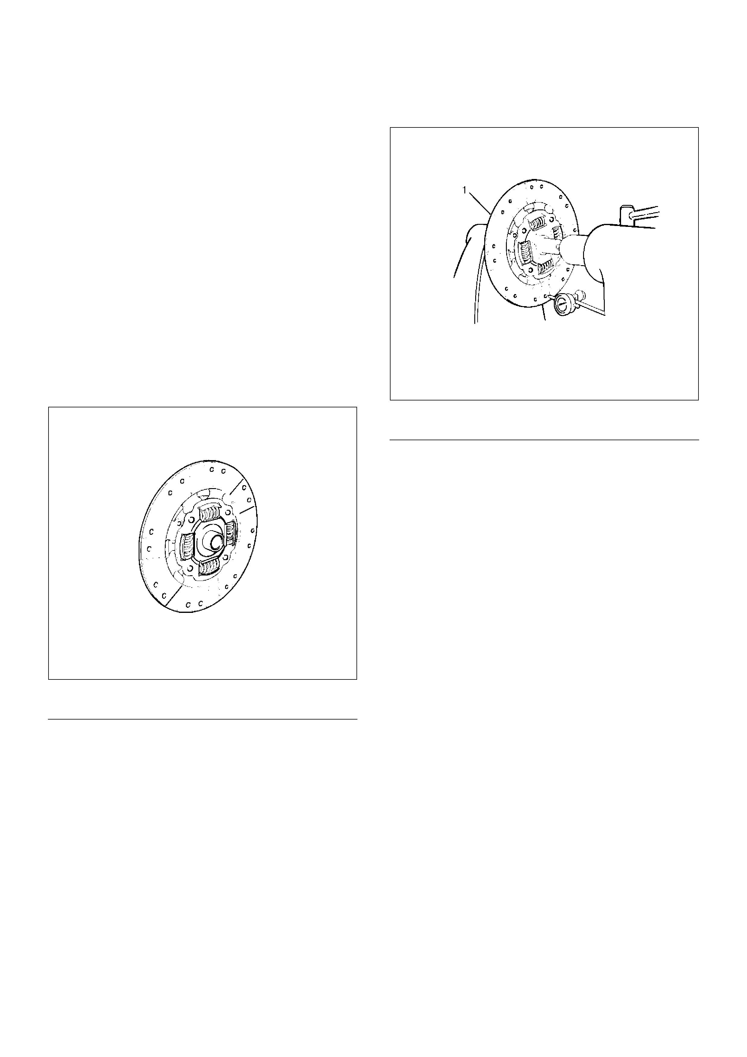
Driven Plate Assembly
201RW033
EndOFCallout
1. Visually check the torsion spring for looseness,
breakage, and weakening.
2. If any of these conditions are discovered, the driven
plate assembly must be replaced.
3. Visually check the facing surfaces for cracking and
excessive scorching.
4. Visually inspect the facing surfaces for the presence
of oil or grease.
5. If any of these conditions are discovered, the facing
must be cleaned or replaced.
6. Check that the driven plate moves smoothly on the
transmission top gear shaft spline.
7. Minor ridges on the top gear shaft spline may be
removed with an oil stone.
Driven Plate Warpage
201RW034
EndOFC allout
1. Insert the clutch pilot aligner into the driven plate
splined hub.
2. The clutch pilot aligner J-24547 must be held
perfectly horizontal.
3. Set a dial indicator to the driven plate outside
circumference.
4. Slowly turn the driven plate.
5. Read the dial indicator as you turn the driven plate.
6. If the measured value exceeds the specified limit,
the driven plate assembly must be replaced.
Driven Plate Warpage
Standard: 0.7mm (0.028in)
Limit: 1.0mm (0.039in)
Legend
Driven Plate Assembly
Legend
(1) Driven Plate Assembly
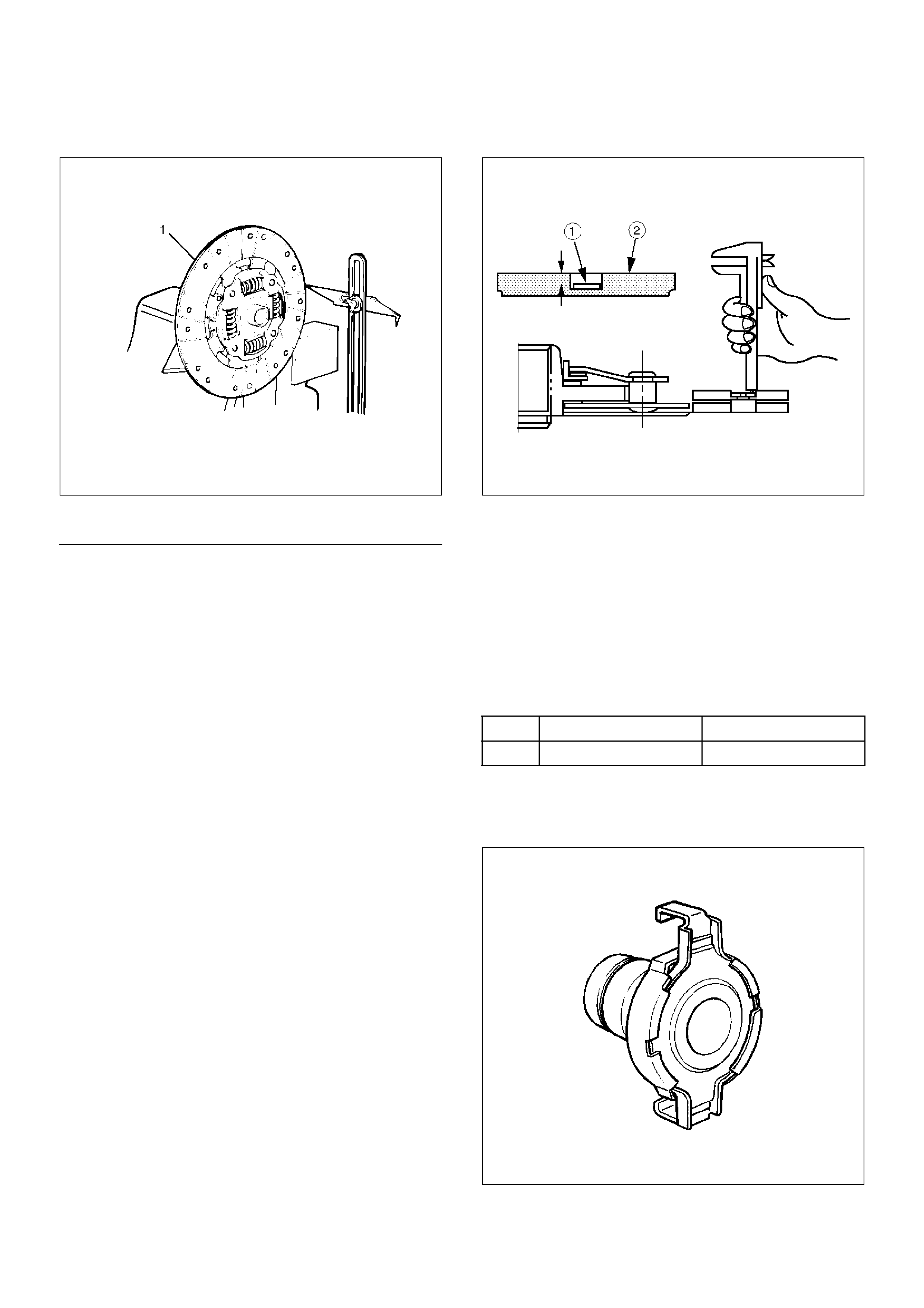
Driven Plate Splined Hub Spline Wear
201RW032
EndOFCallout
1. Clean the driven plate splined hub.
2. Install the driven plate to the transmission top gear
shaft spline.
3. Set a surface gauge to the driven plate outside
circumference.
4. Slowly turn the driven plate counterclockwise.
5. Measure the spline rotation play as you turn the
driven plate.
6. If the measured value exceeds the specified limit,
the driven plate assembly must be replaced.
Driven Plate Splined Hub Spline Wear
Standard: 0.5mm (0.020in)
Limit: 1.0mm (0.039in)
Rivet Head Depression
201RS010
1. Use a depth gauge or a straight edge with steel rule
to measure the rivet head depression 1 from the
facing surface 2.
2. Be sure to measure the rivet head depression on
both sides of the driven plate.
3. If the measured value is less than the specified limit,
the driven plate assembly must be replaced.
Rivet Head Depression
Standard:
Limit: 0.2mm (0.008in)
Release Bearing
201RS011
1. Visually check the release bearing for excessive
play, noise and breakage.
Legend
(1) Driven Plate Assembly
Flywheel side Pressure plate side
6VE1 1.95mm(0.077in) 1.95mm(0.077in)
2. If any of these conditions are discovered, the
release bearing must be replaced.
3. When replacing the release bearing, replace both
the wedge collar and wire ring at the same time.
201RW010
EndOFCallout
Wedge Collar
201RS013
1. Visually check the surfaces of the wedge collar
making contact with the release bearing for
excessive wear and damage.
2. Replace any exhibiting excessive wear or damage.
Shift Fork
201RS014
1. Visually check the surfaces of the shift fork making
contact with the release bearing for excessive wear
and damage.
2. Remove any minor stepping or abrasion from shift
fork with an oil stone.
3. Replace any exhibiting excessive wear or damage.
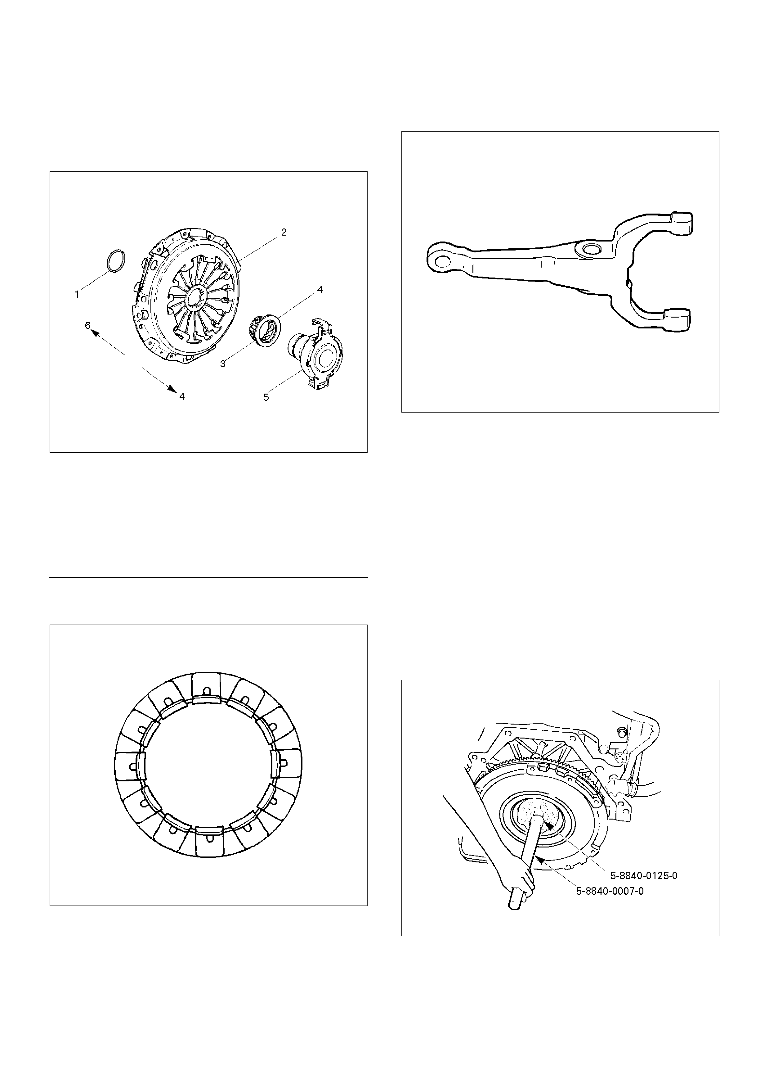
Installation
To install, follow the removal steps in the reverse order,
noting the following points:
1. Install flywheel assembly and crankshaft bearing.
Use the installer 5-8840-0125-0 (J-26516-A) and
driver handle 5-8840-0007-0 (J-8092) to install the
crankshaft bearing then clean and lubricate with
grease.
015RW054
2. Install new flywheel fixing bolts in the order
illustrated and tighten them to the specified torque.
Torque:
6VE1: 54N·m (5.5kg·m/40lbft)
Legend
(1) Wire Ring
(2) Pressure Plate Assembly
(3) Wedge Collar
(4) T/M Side
(5) Release Bearing
(6) Engine Side

NOTE: Do not reuse the bolt and do not apply oil or
thread lock to the bolt.
015RS047
3. Install the front cover (5) to the transmission case.
4. Tighten eight front cover bolts to the specified
torque.
Torque: 17N·m (1.7kg·m/12lbft)
220RW088
5. Apply molybednum disulfide type grease to the pin
hole inner circumferences and thrust surfaces.
6. Attach the shift fork to the front cover and insert the
pin from below of the front cover.
7. Install the washer and snap pin.
201RW019
8. Apply molybdenum disulfide type grease to the
areas shown in illustration.
201RW012
9. Install the release bearing in the proper direction.
NOTE: Ensure release bearing is properly positioned
during installation, as shown in illustration.
201RW020
10. Install driven plate assembly. Use the pilot aligner
5-85253-001-0 (J-24547) to install the driven plate
assembly.
201RW027
11. Install pressure plate assembly and tighten the bolts
holding the pressure plate assembly in the order
shown in illustration.
Torque: 18N·m (1.8kg·m/13lbft)
201RS017
12. Remove the aligner.
NOTE: Do not strike the aligner with a hammer to
remove it.
13. Install transmission assembly.
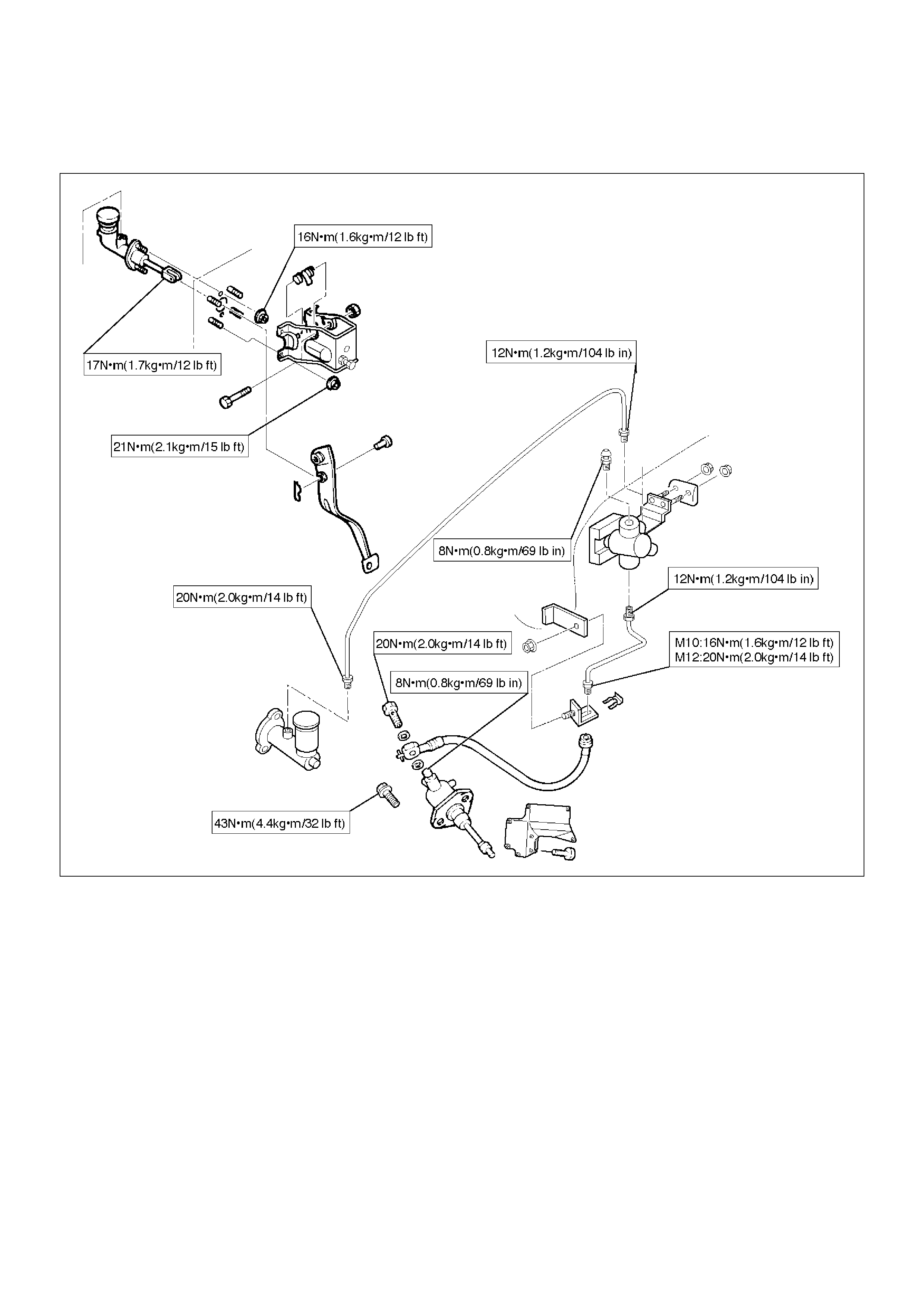
Clutch Control
Clutch Control Parts
203RW009
EndOFCallout
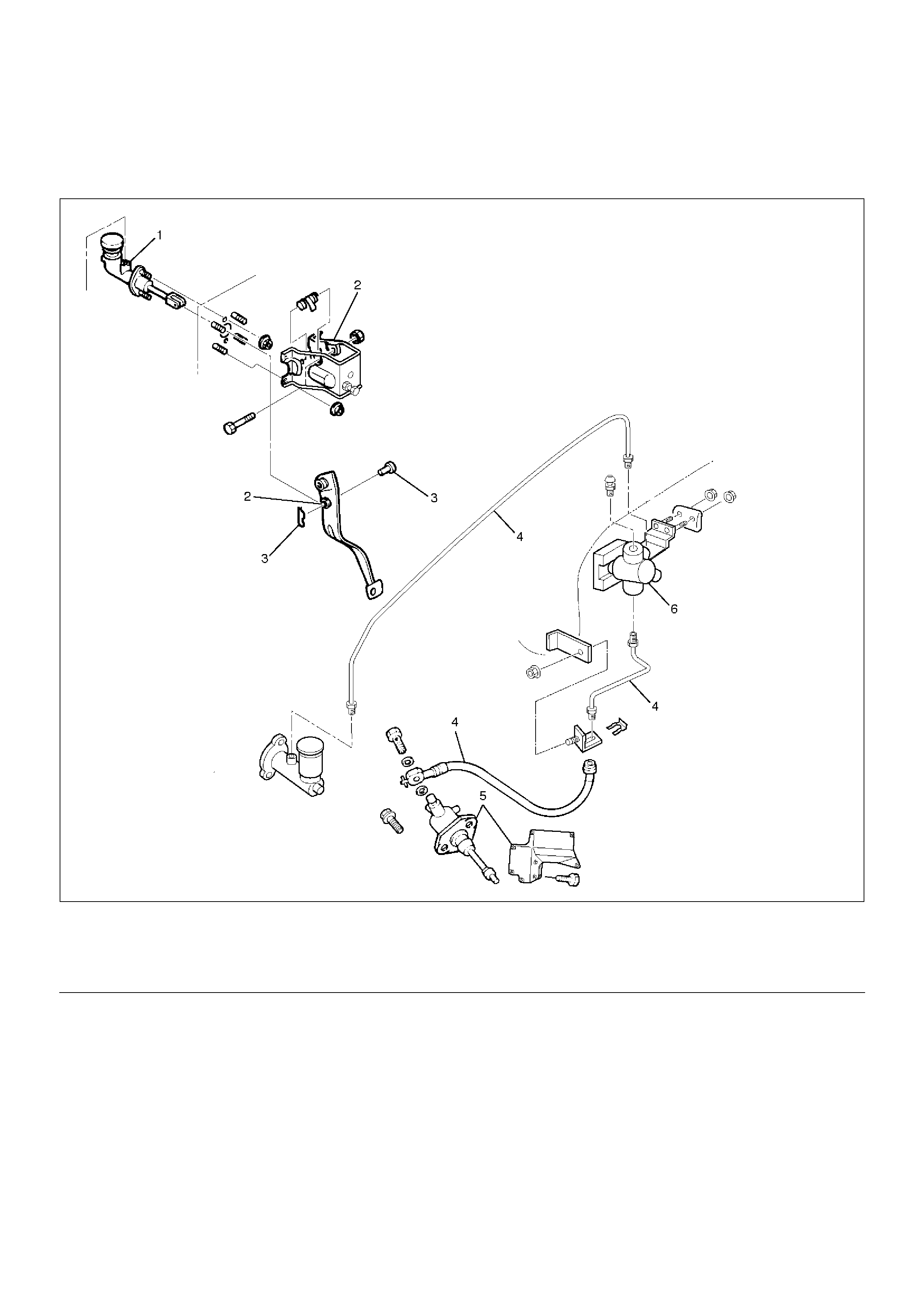
Removal
1. Remove pin and jaw joint pin.
2. Remove pedal assembly.
3. Remove oil line pipe.
4. Remove slave cylinder assembly and heat
protector.
5. Remove master cylinder assembly.
6. Remove damper cylinder assembly
Inspection and Repair
Make necessary adjustments, repairs, and part
replacement if wear, damage or other problems are
discovered during inspection.
Legend
(1) Master Cylinder Assembly
(2) Pedal Assembly
(3) Pin and Joint Pin
(4) Oil Line Pipe
(5) Slave Cylinder Assembly and Heat Protector
(6) Damper Cylinder Assembly
Installation
1. Install damper cylinder assembly
2. Install master cylinder assembly.
3. Install slave cylinder assembly and heat protector.
4. Install oil line pipe.
5. Install pedal assembly.
6. Install pin and jaw joint pin.
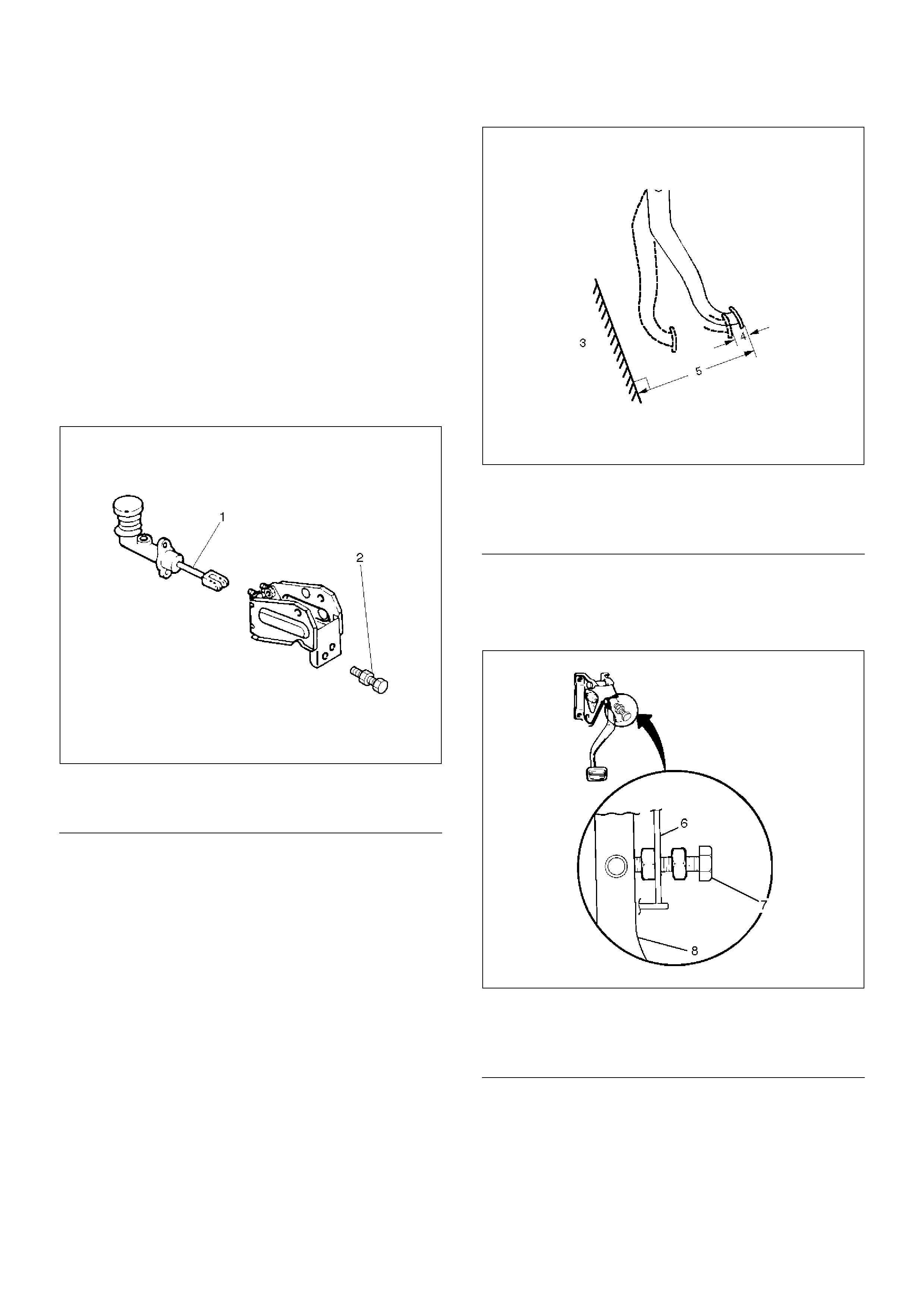
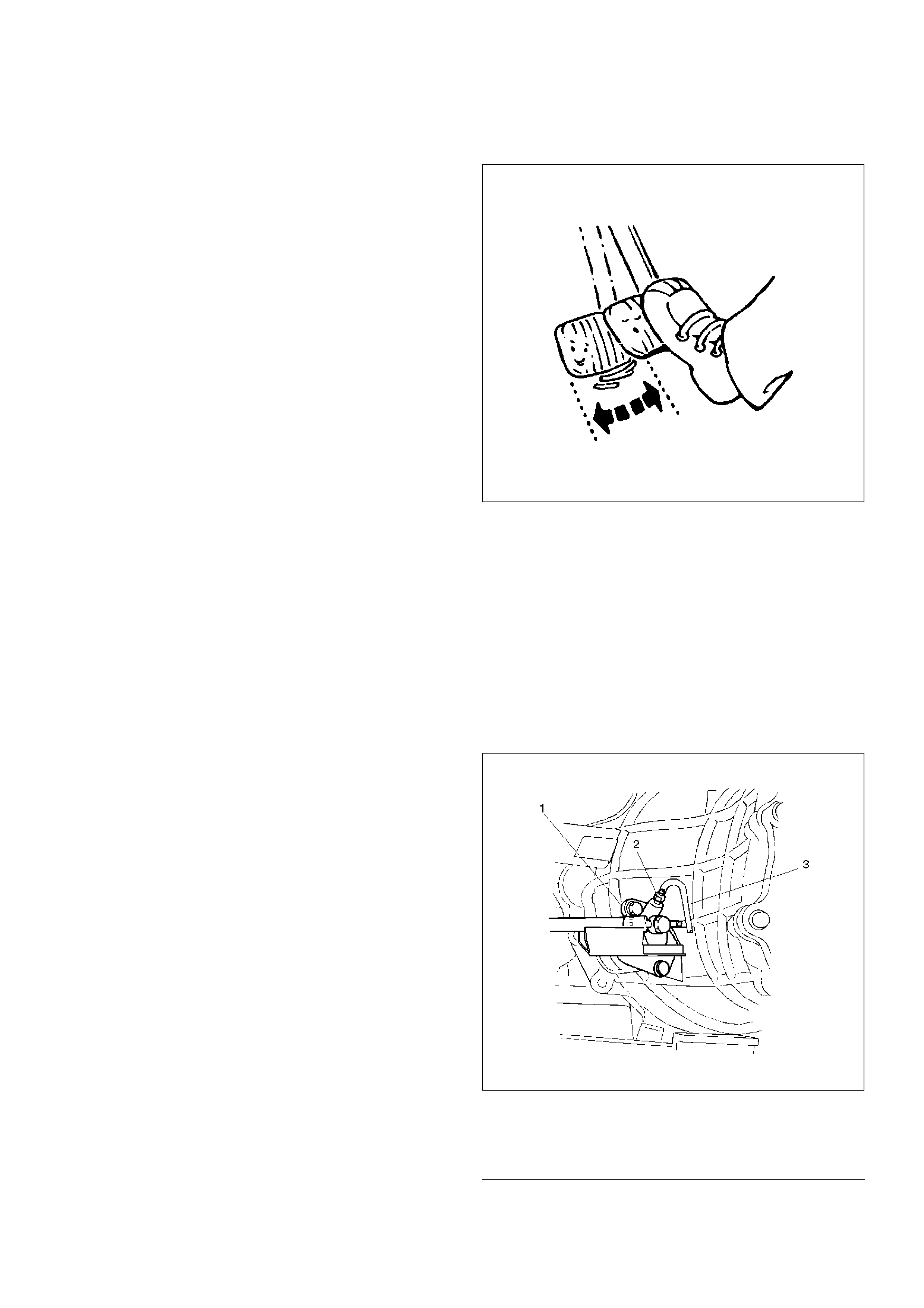
Adjustment
Clutch Pedal Adjustment
1. Loosen the clutch pedal adjusting bolt so that there
is enough gap between the clutch pedal and the
adjusting bolt to allow push rod adjustment.
203RW011
EndOFCallout
2. Loosen clutch master cylinder push rod lock nut.
Turn push rod by hand to set clutch pedal height (5)
to within specification.
Clutch pedal height (5):
238.5mm – 248.5mm (9.390in – 9.783in)
203RW004
EndOFCallout
3. Tighten push rod lock nut.
4. Adjusting bolt adjustment.
1. Turn the adjusting bolt until it just touches the
clutch pedal arm.
203RW012
EndOFCallout
Legend
(1) Push Rod
(2) Adjusting Bolt
Legend
(3) Floor Panel
(4) Pedal Free Play
(5) Clutch Pedal Height
Legend
(6) Bracket
(7) Adjusting Bolt
(8) Clutch Pedal Arm
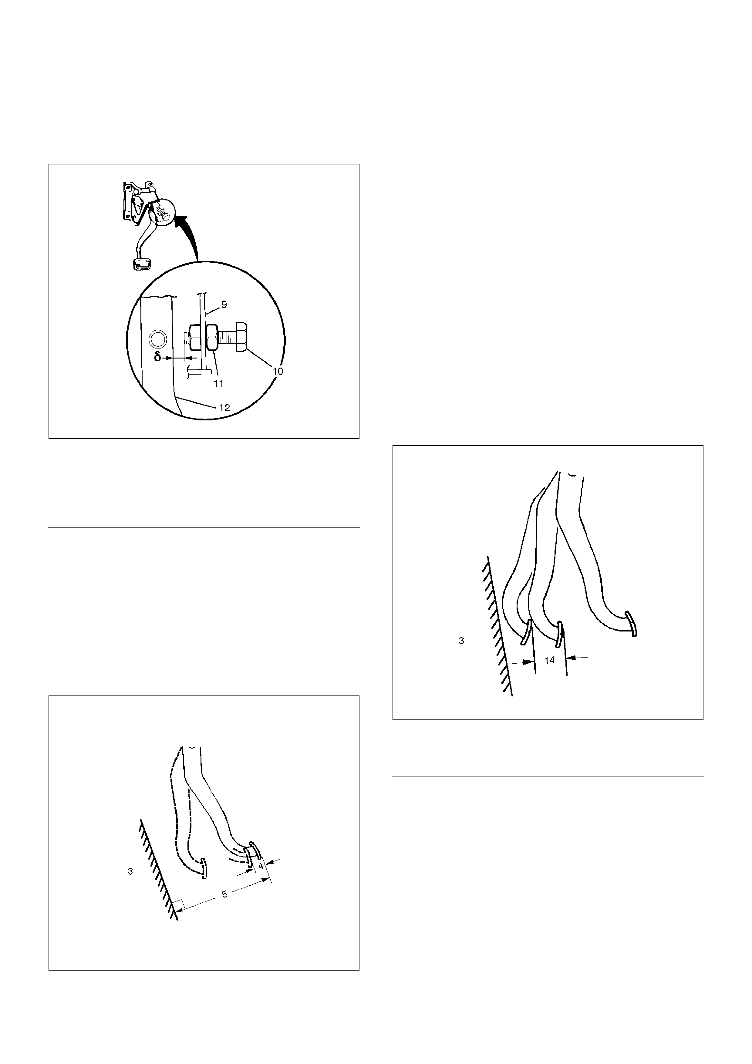
2. Adjust clutch padel adjusting bolt by backing it
out half a turn, and measure the clearance (d)
between the clutch pedal arm and the adjusting
bolt.
203RW010
EndOFCallout
3. Lock the lock nut.
Clutch Switch and Clutch Pedal Clearance (d)
0.5mm – 1.5mm (0.020 in – 0.059in)
5. After adjusting the clutch pedal height, push the
clutch pedal by hand rightly to check the clutch
pedal free play (4) to within specification.
Pedal Free Play (4)
5mm – 15mm (0.20in – 0.59in)
203RW004
6. Clutch pedal engagement height inspection:
1. Operate the parking brake lever and block the
wheels.
2. Start the engine, fully step on the clutch pedal,
and move the shift lever to 1st position.
3. With the engine idling, release the clutch pedal
slowly and measure its stroke just prior to its
clutching position.
Clutch Pedal Engagement Height (14)
MIN.30mm (1.18in)
7. If the measured value exceeds the specified limit,
check the following points. Repair if necessary:
• Hydraulic circuit for fluid leakage or air in circuit.
• Clutch disc warped.
• Diaphragm spring weakened or tip of fingers
worn.
• Driven plate sticking on sprines.
• Release bearing worn or damaged.
• Master cylinder and slave cylinder worn.
203RW007
EndOFCallout
Legend
(9) Bracket
(10) Clutch Pedal Adjusting Bolt
(11) Lock Nut
(12) Clutch Pedal Arm
Legend
(3) Floor Panel
(14) Clutch Pedal Engagement Height
Torque Specifications
• Master cylinder to dash panel
Torque: 16N·m (1.6kg·m/12lbft)
• Clutch pedal to dash panel
Torque: 21N·m (2.1kg·m/15lbft)
• Master cylinder push rod to yoke
Torque: 17N·m (1.7kg·m/12lbft)
• Clutch pipe to master cylinder
Torque: 20 N·m (2.0 kg·m/14lbft)
• Clutch pipe to flex, hose
Torque:
M 10: 16N·m (1.6kg·m/12lbft)
M 12: 20N·m (2.0kg·m/14lbft)
• Slave cylinder to case
Torque: 43N·m (4.4kg·m/32lbft)
• Slave cylinder bleeder screw
Torque: 8N·m (0.8kg·m/69lbin)
• Flexible hose to slave cylinder
Torque: 20N·m (2.0kg·m/14lbft)
• Clutch pipe to damper cylinder
Torque: 12N·m (1.2kg·m/104lbin)
• Damper cylinder bleeder screw
Torque: 8N·m (0.8kg·m/69lbin)
Bleeding
1. Check the level of clutch fluid in the reservoir and
replenish if necessary.
Bleeding the damper cylinder
Remove the rubber cap from the bleeder screw and
wipe clean the bleeder screw. Connect a vinyl tube
to the bleeder screw and insert the other end of the
vinyl tube into a transparent container.
2. Pump the clutch pedal repeatedly and hold it
depressed.
203RS005
3. Loosen the bleeder screw to release clutch fluid with
air bubbles into the container, then tighten the
bleeder screw immediately.
4. Release the clutch pedal carefully. Repeat the
above operation until air bubbles disappear from the
clutch fluid being pumped out into the container.
During the bleeding operation, keep the clutch fluid
reservoir filled to the specified level. Reinstall the
rubber cap.
Bleeding the slave cylinder
5. Repeat step 2 through 5 for bleeding the slave
cylinder.
206RW003
EndOFCallout
Legend
(1) Slave Cylinder
(2) Bleeder Screw
(3) Vinyl Tube

Master Cylinder
Disassembled View
208RW016
EndOFCallout
Legend
(1) Master Cylinder Assembly
(2) Gasket
(4) Nut
(5) Push Rod Damper

Disassembly
(4JX1)
1. Remove damper cylinder assembly and gasket.
2. Remove push rod damper.
NOTE: The master cylinder assembly cannot be
disassembled because of point–staked rod stopper.
Inspection and Repair
Clean and inspect the removed parts.
Make necessary parts replacement if any abnormalities
such as wear, oil leaks or other damage are found
through inspection.
Reassembly
To reassemble, follow the disassembly steps in the
reverse order, noting the following points:
1. Push rod set length
117.5 mm (4.626 in)
2. Push rod nut torque
17 N·m (1.7 kg·m/12 Ib ft)
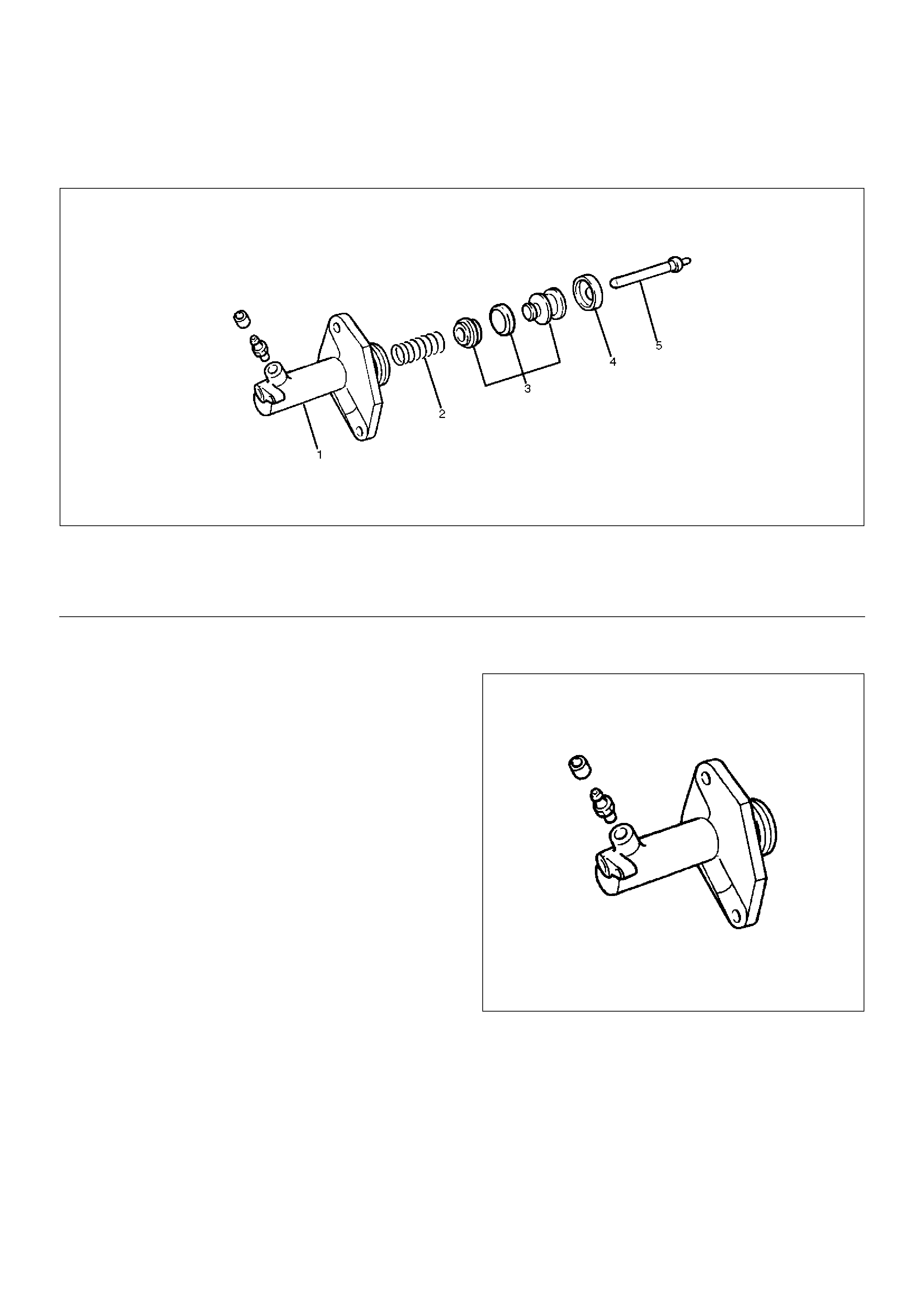
Slave Cylinder
Disassembled View
206RW004
EndOFCallout
Disassembly
1. Remove boot.
2. Remove push rod.
3. Remove piston and piston cup.
4. Remove spring.
Inspection and Repair
Make the necessary adjustments, repairs, and part
replacements if excessive wear or damage is
discovered during inspection.
Cylinder Body
206RS003
1. Clean the cylinder body.
2. Check the fluid return port for restrictions and clean
it if necessary.
Legend
(1) Cylinder Body
(2) Spring
(3) Piston and Piston Cup
(4) Boot
(5) Push Rod
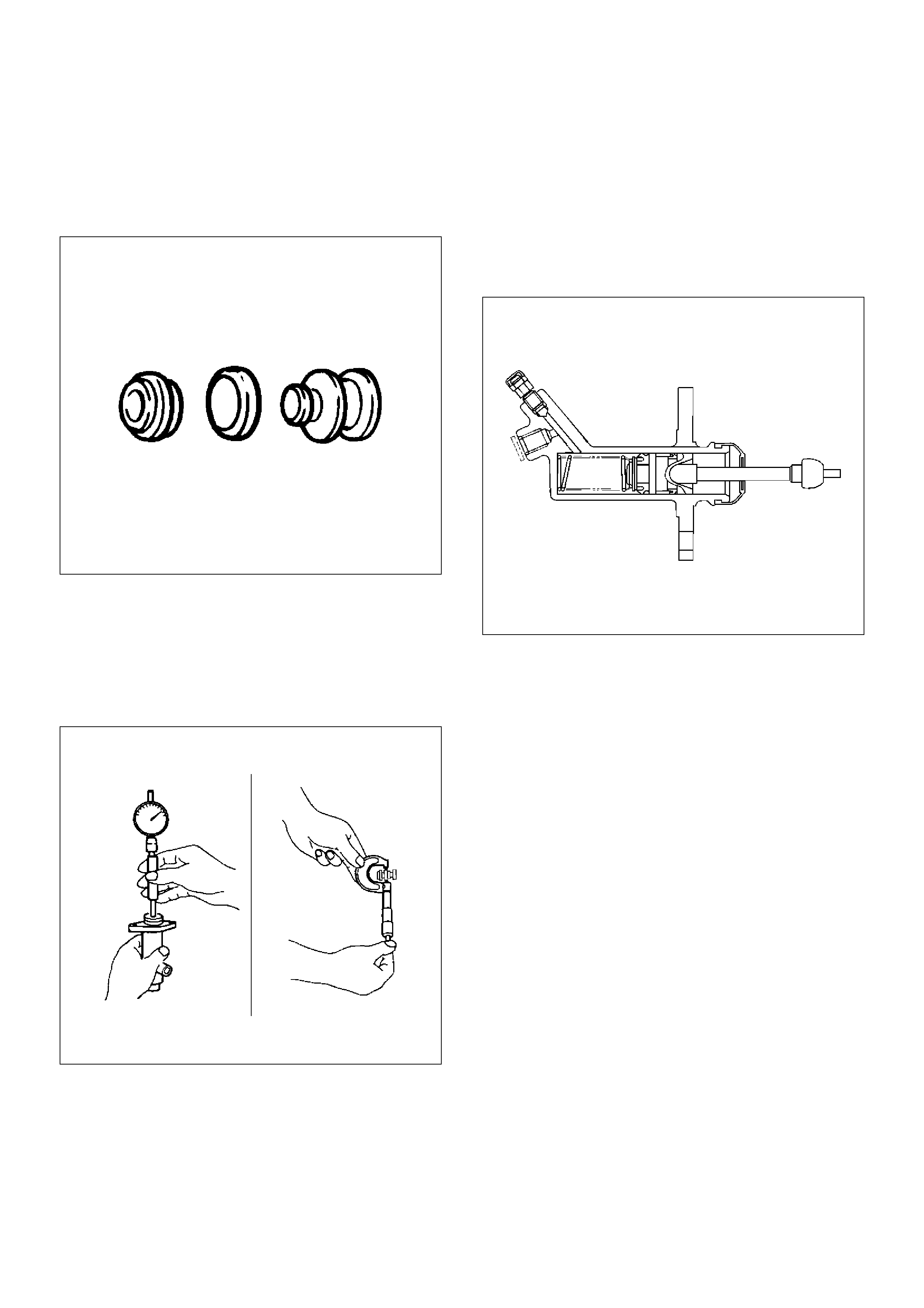
Piston and Piston Cup
1. Visually inspect the disassembled piston and piston
cup for excessive wear and damage.
2. Replace the inner parts with new parts shown in the
illustration.
206RS004
3. Measure the clearance between slave cylinder wall
and piston.
4. If the measured value exceeds the specified limit,
the slave cylinder assembly must be replaced.
Standard: 0.07mm (0.0028 in)
Limit: 0.15mm (0.0059 in)
206RS005
Reassembly
To reassemble, follow the disassembly steps in the
reverse order, noting the following points:
1. Before installing the parts, apply a thin coat of
rubber grease.
2. Install cup in groove in piston with the lip turned to
the front of cylinder. Use care so as not to scratch
the cylinder.
206RS006
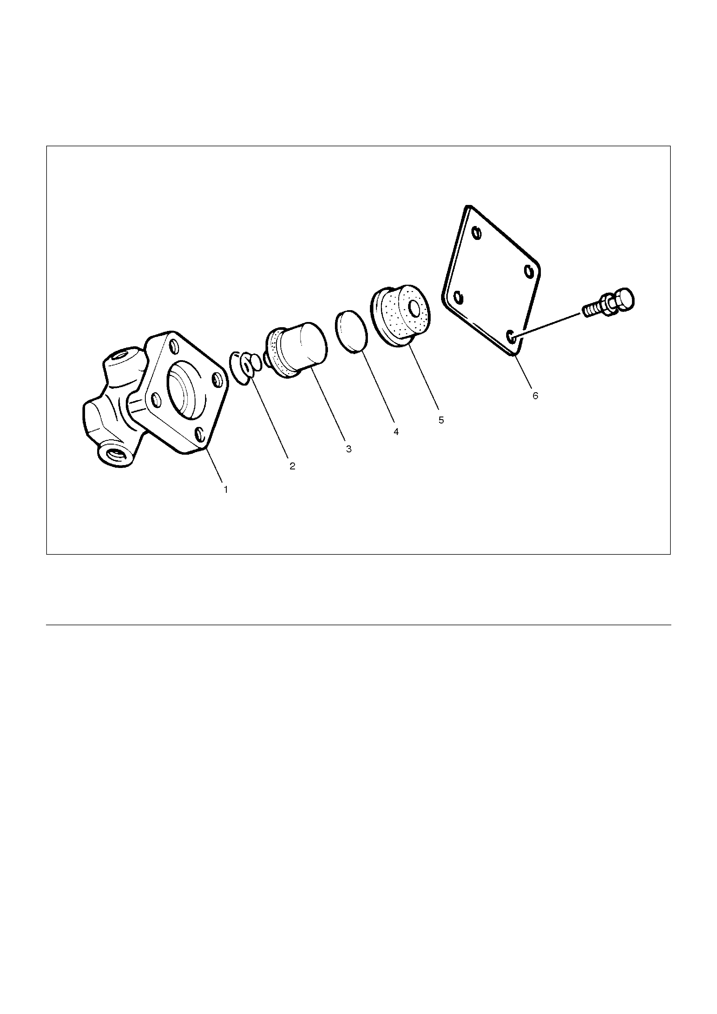
Damper Cylinder
Disassembled View
205RW005
EndOFCallout
Disassembly
1. Remove cover and gasket.
2. Remove damper rubber.
3. Remove spacer.
4. Remove piston assembly.
5. Remove spring.
Inspection and Repair
Check damper rubber and piston cup for cracks,
deformation or damage.
Replace the damper cylinder assembly if necessary.
Reassembly
To assemble, follow the disassembly steps in the
reverse order.
Legend
(1) Cylinder Body
(2) Spring
(3) Piston Assembly
(4) Spacer
(5) Damper Rubber
(6) Cover and Gasket
Main Data and Specifications
General Specifications
Torque Specifications
E07RW053
Type Dry single plate type with diaphragm spring
Size 275mm(10.83in)
Pressure plate Outside diameter 332mm(13.07in)
Pressure plate Clamping force 7208N(1621lb)
Pressure plate Spring finger height 49.9–51.9mm(1.965–2.043in)
Driven plate Outside diameter x inside diameter 275´180 mm(10.83´6.69in)
Thickness Clutch disengaged 8.8mm(0.346in)
Thickness Clutch engaged 8.3mm(0.327in)
Total friction area 339´2cm (52 ´2in )
Clutch control type Hydraulic
Clutch pedal free play 5–15mm(0.20– 0.59in)
Clutch pedal height 238.5mm – 248.5mm (9.390in – 9.783in)
Clutch pedal stroke 152.5– 162.5mm(6.004– 6.398in)
Torque Specifications (Cont'd)
E07RW055
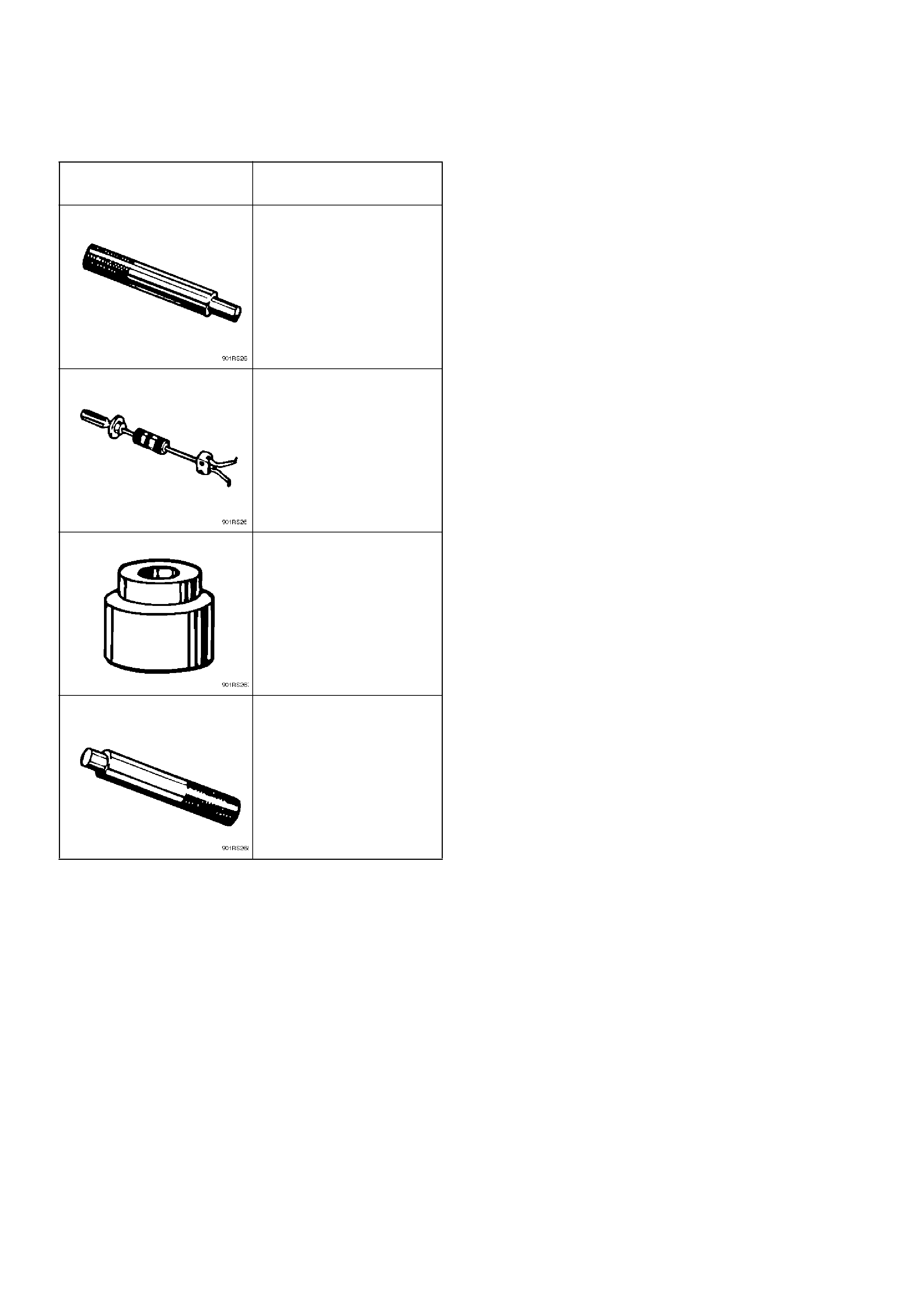
Special Tools
ILLUSTRATION TOOL NO.
TOOL NAME
5-85253-001-0
(J-24547)
Driven plate aligner
5-8840-2000-0 and
5-8840-0019-0
(J-5822 and J-23907)
Pilot bearing remover and
Sliding hammer
5-8840-0125-0
(J-26516-A)
Crankshaft pilot bearing
installer
5-8840-0007-0
(J-8092)
Driver handle