
SECTION 7B - AR-5 MANUAL TRANSMISSION
Service Precaution
General Description
Diagnosis
Manual Transmission Assembly
Transmission and Associated Parts
Removal
Installation
Rear Oil Seal (Transfer Adapter)
Removal
Installation
Transmission (AR-5)
Disassembled View
Disassembly
Inspection
Reassembly
Main Data and Specifications
General Specifications
Torque Specifications
Special Tools
Service Precaution
WARNING: IF SO EQUIPPED WITH A
SUPPLEMENTAL RESTRAINT SYSTEM (SRS),
REFER TO THE SRS COMPONENT AND WIRING
LOCATION VIEW IN ORDER TO DETERMINE
WHETHER YOU ARE PERFORMING SERVICE ON
OR NEAR THE SRS COMPONENTS OR THE SRS
WIRING. WHEN YOU ARE PERFORMING SERVICE
ON OR NEAR THE SRS COMPONENTS OR THE
SRS WIRING, REFER TO THE SRS SERVICE
INFORMATION. FAILURE TO FOLLOW WARNINGS
COULD RESULT IN POSSIBLE AIR BAG
DEPLOYMENT, PERSONAL INJURY, OR
OTHERWISE UNNEEDED SRS SYSTEM REPAIRS.
CAUTION: Always use the correct fastener in the
proper location. When you replace a fastener, use
ONLY the exact part number for that application.
HOLDEN will call out those fasteners that require a
replacement after removal. HOLDEN will also call
out the fasteners that require thread lockers or
thread sealant. UNLESS OTHERWISE SPECIFIED,
do not use supplemental coatings (Paints, greases,
or other corrosion inhibitors) on threaded fasteners
or fastener joint interfaces. Generally, such
coatings adversely affect the fastener torque and
the joint clamping force, and may damage the
fastener. When you install fasteners, use the correct
tightening sequence and specifications. Following
these instructions can help you avoid damage to
parts and systems.
Techline
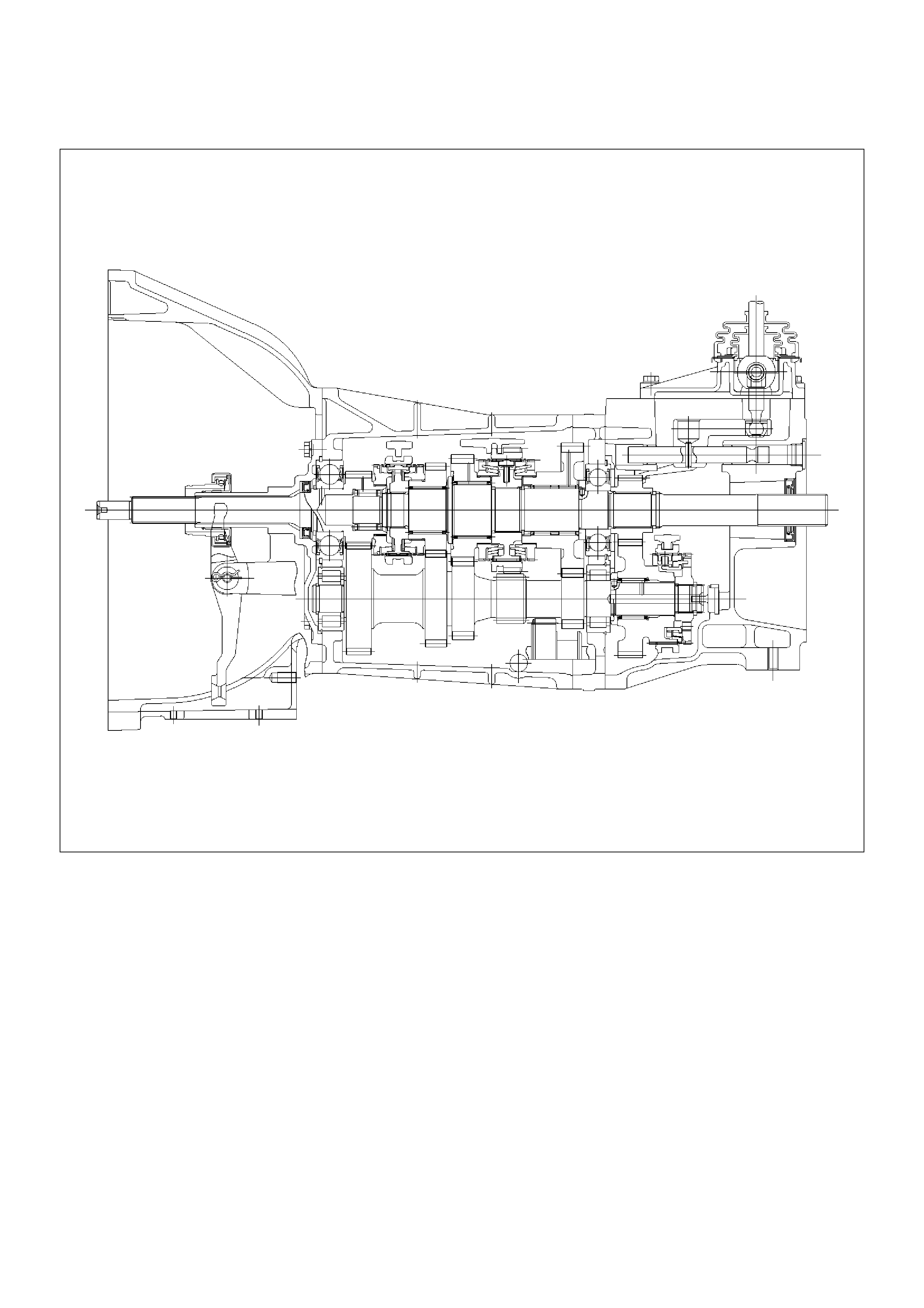
General Description (6VE1)
A07RW044
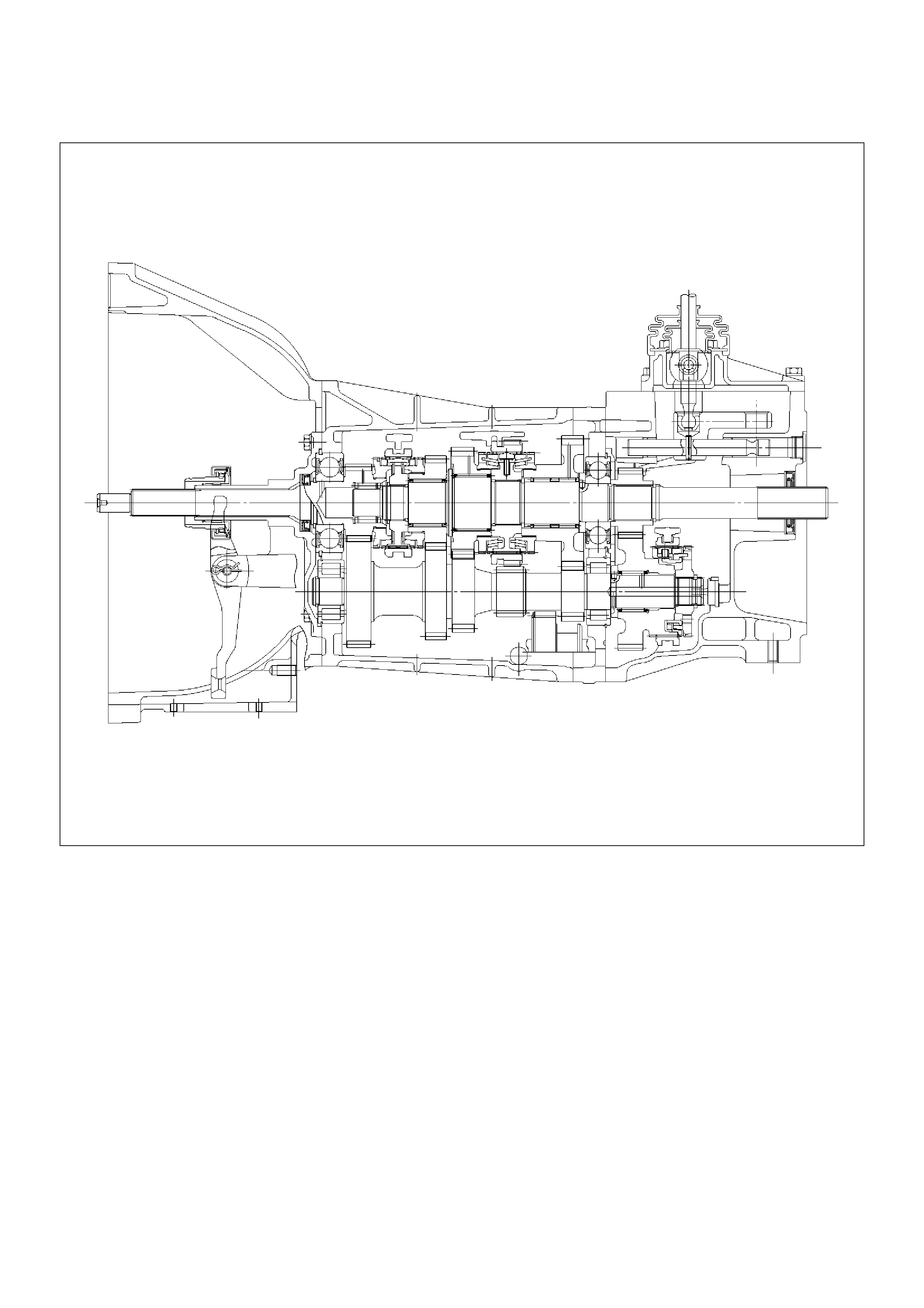
(4JX1)
A07RW043

Diagnosis
Condition Possible Cause Correction
Abnormal noise Flywheel pilot bearing worn Replace
Bearings worn or broken (Mainshaft,
counter shaft, and transfer shaft)
Replace
Gear tooth contact surfaces worn or
scuffed (Mainshaft, counter shaft,
reverse idler gear and transfer gears)
Replace
Splines worn (Mainshaft,
synchronizer clutch hub)
Replace
Gear or bearing thrust face seized Replace
Lack of backlash between meshing
gears
Replace
Hard Shifting Improper clutch pedal free play Readjust
Change lever sliding portions worn Repair or replace
Regrease
Shift block, shift rod and/or control
box sliding faces worn
Replace
Shift arm and synchronizer sleeve
groove worn
Replace worn parts
Thrust washer, collar, and/or gear
thrust faces worn (Mainshaft and
counter shaft thrust play)
Replace worn parts
Synchronizer parts worn Replace
Walking or Jumping out of gear Detent ball worn Replace
Detent spring weakened or broken Replace
Shift rod and/or control box sliding
faces worn
Replace
Shift arm and synchronizer sleeve
groove worn
Replace worn parts
Thrust washer, collar, and/or gear
thrust faces worn (Mainshaft and
counter shaft thrust play)
Replace worn parts
Bearings worn or broken Replace
Splines worn (Mainshaft,
synchronizer hub)
Replace
Synchronizer spring weakened or
broken
Replace
Oil leakage Loose drain plug(s) and/or filler
plug(s)
Tighten
Replenish oil
Defective or improperly installed
gasket(s)
Replace
Oil seal worn or scratched Replace
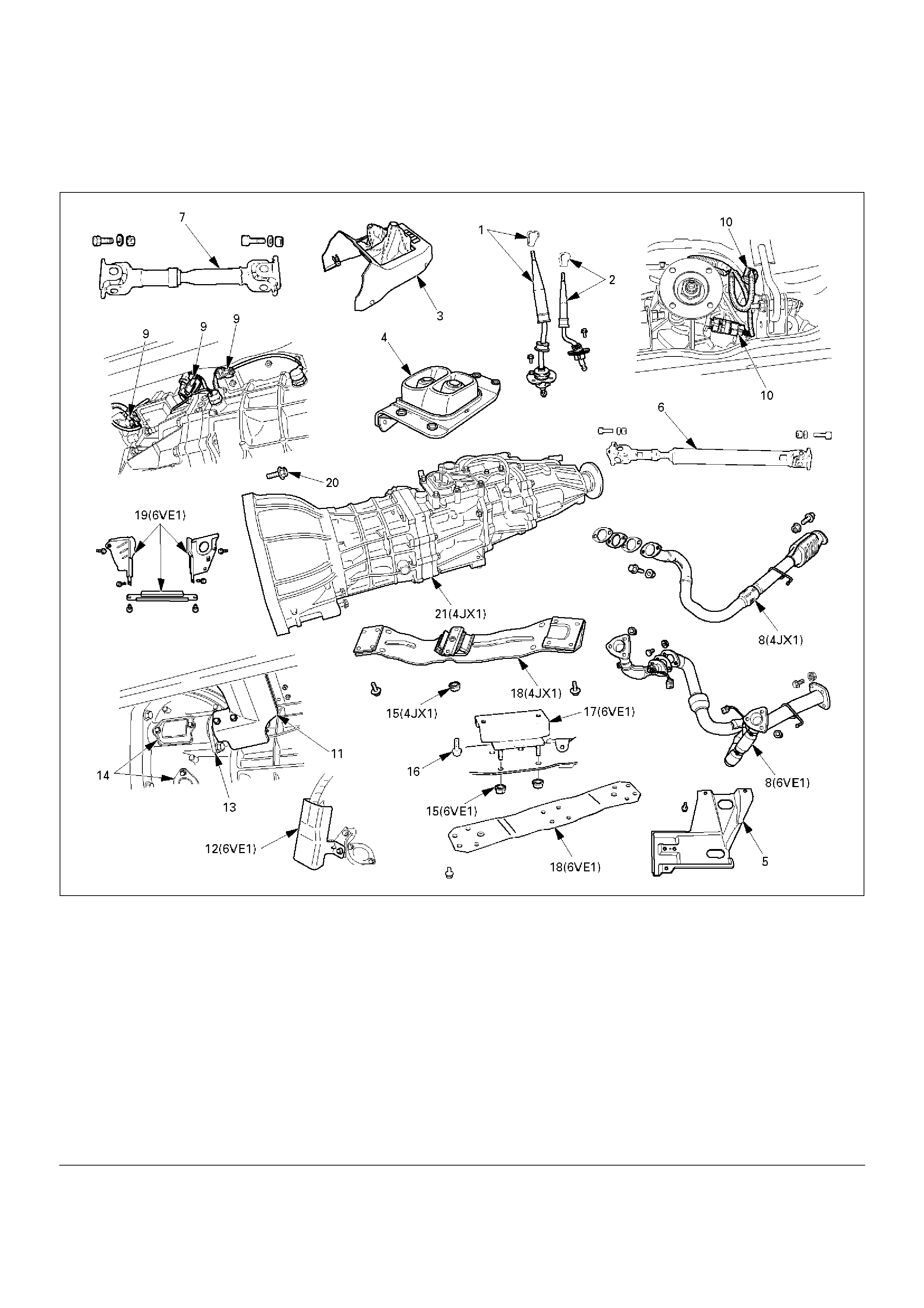
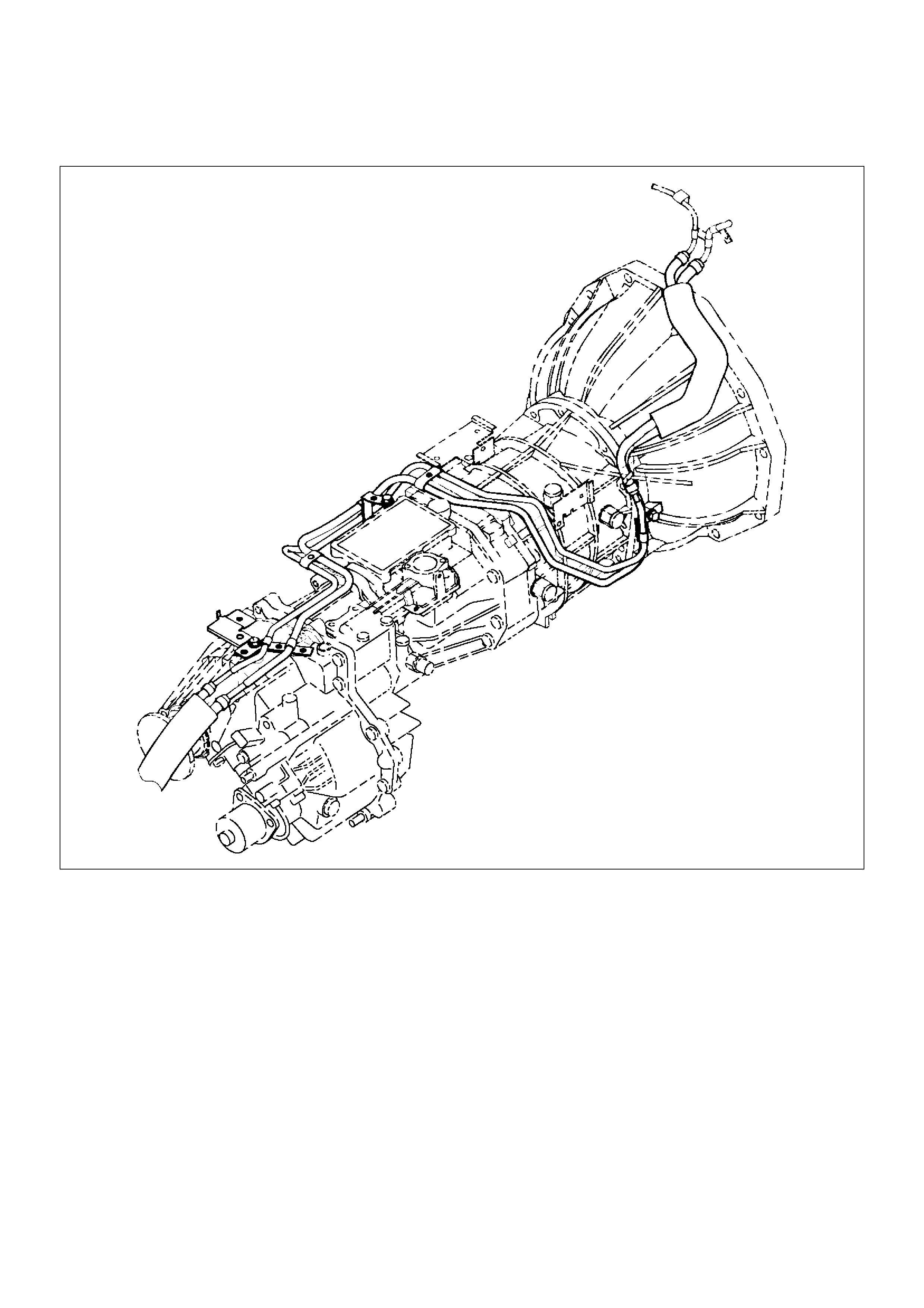
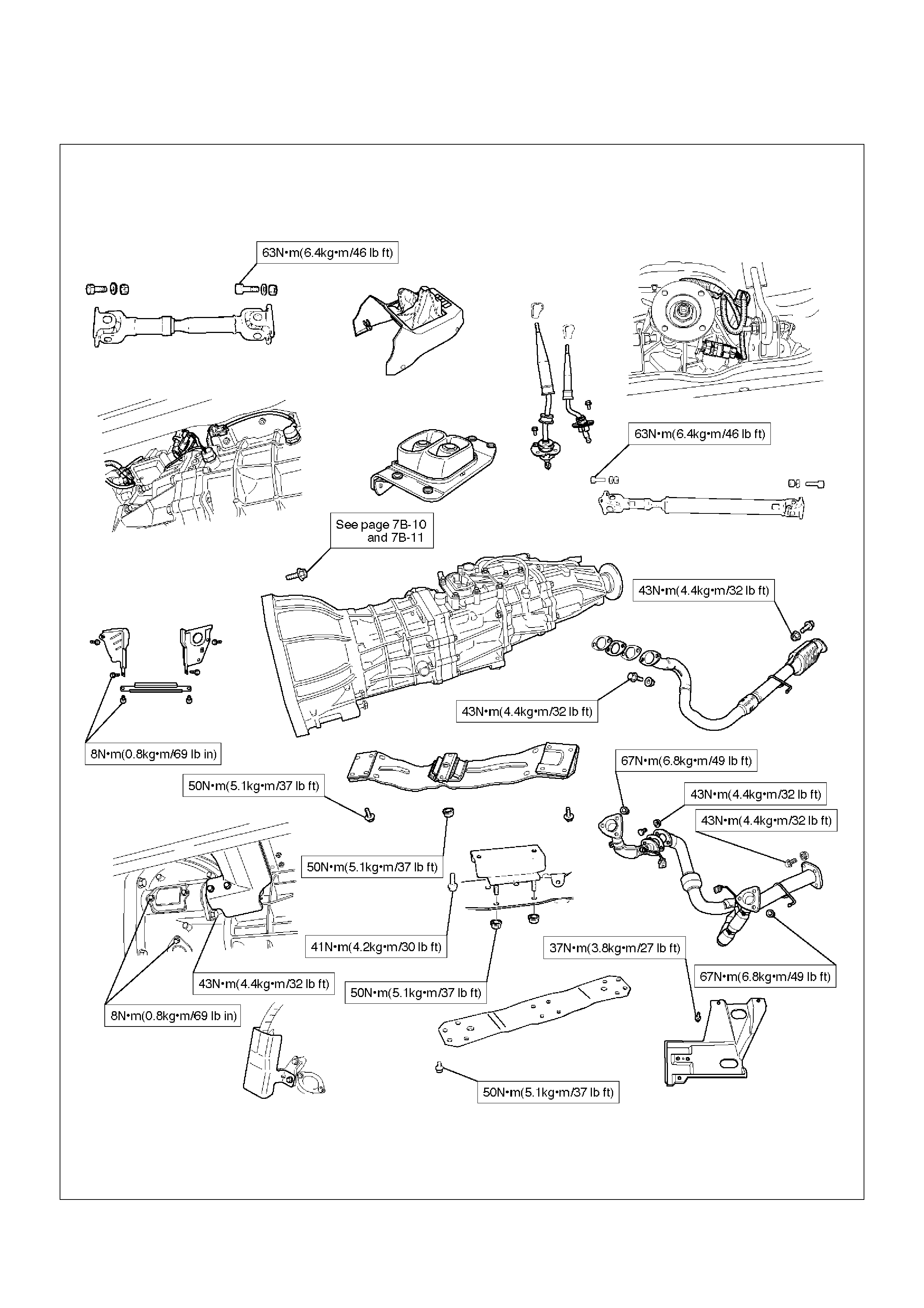
Manual Transmission Assembly
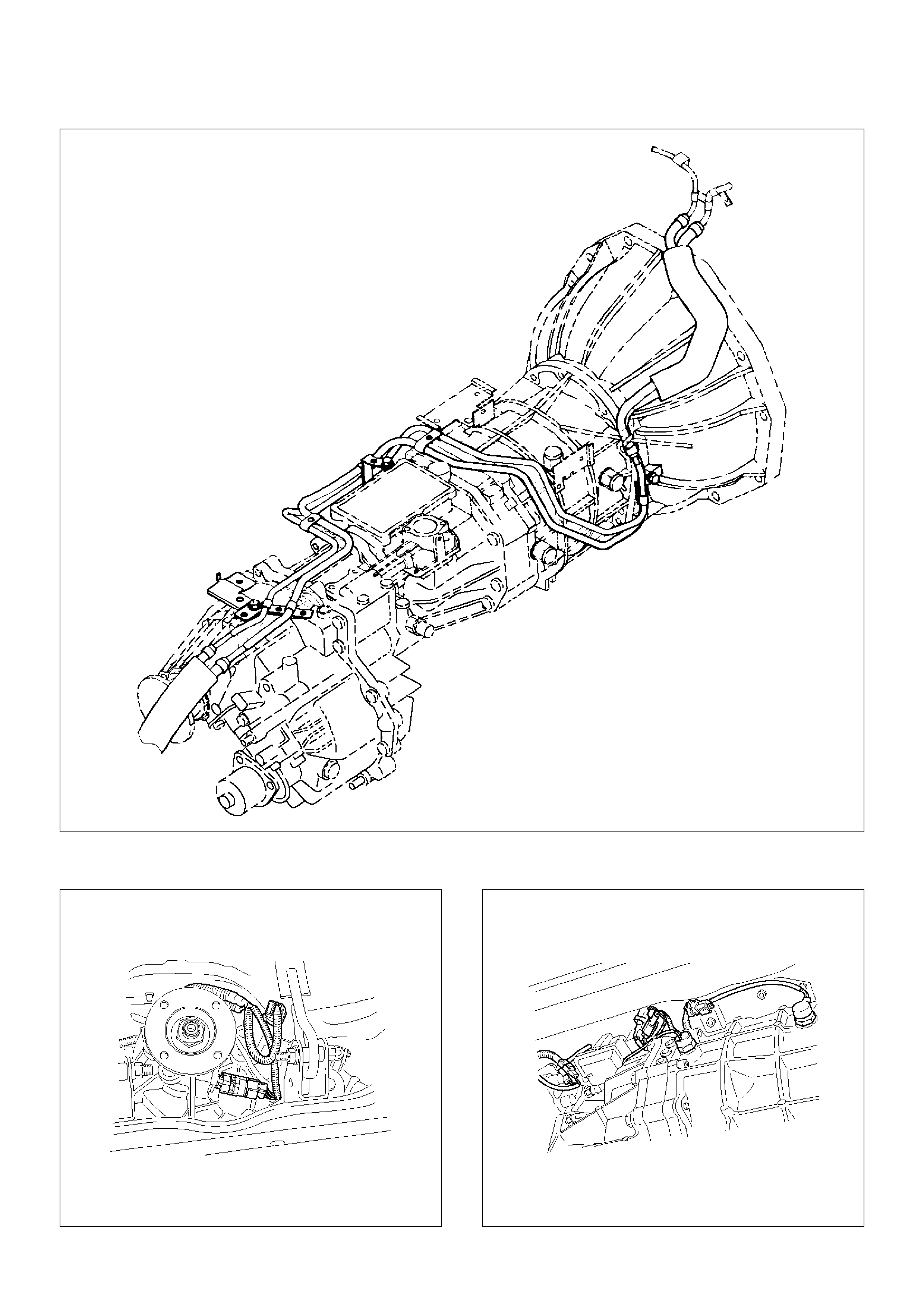
Transmission and Associated Parts
220RW108
EndOFCallout
Legend
(1) Gear Control Lever and Knob
(2) Transfer Control Lever and Knob
(3) Front Console Assembly
(4) Grommet Assembly
(5) Transfer Protector
(6) Rear Propeller Shaft
(7) Front Propeller Shaft
(8) Exhaust Pipe
(9) Backup Lamp, 4WD Indicator, and 1–2
Indicator Switch Harness Connector
(10) Speedometer Sensor and 2WD–4WD Actuator
Harness Connector
(11) Slave Cylinder Heat Protector
(12) Harness Heat Protector
(13) Slave Cylinder
(14) Dust Cover
(15) Engine Rear Mount Nut
(16) Engine Rear Mount Bolt
(17) Engine Rear Mount
(18) Third Crossmember
(19) Flywheel Under Cover
(20) Transmission Retaining Bolt
(21) Transmission Assembly with Transfer Case
Removal
NOTE: Before remove the transmission and transfer
assembly from the vehicle, change the transfer mode to
2WD using push button on dash panel.
1. Remove engine hood.
2. Disconnect battery ground cable.
3. Remove the gear control lever knob.
4. Remove the front console assembly.
5. Remove the grommet assembly.
6. Remove the transmission control lever and transfer
control lever.
235RW014
7. Raise and support the vehicle with suitable jack
stand.
8. Remove transfer protector.
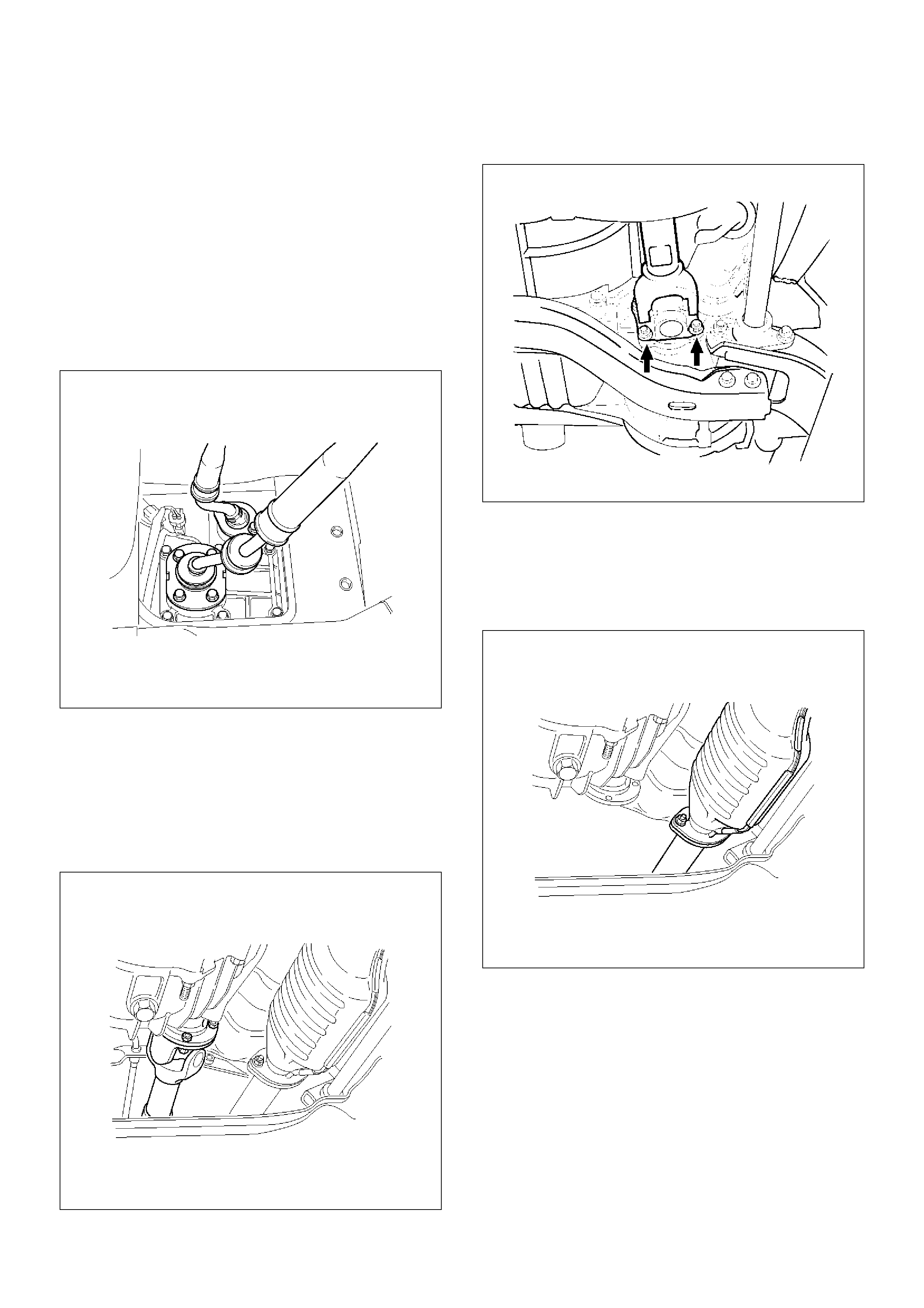
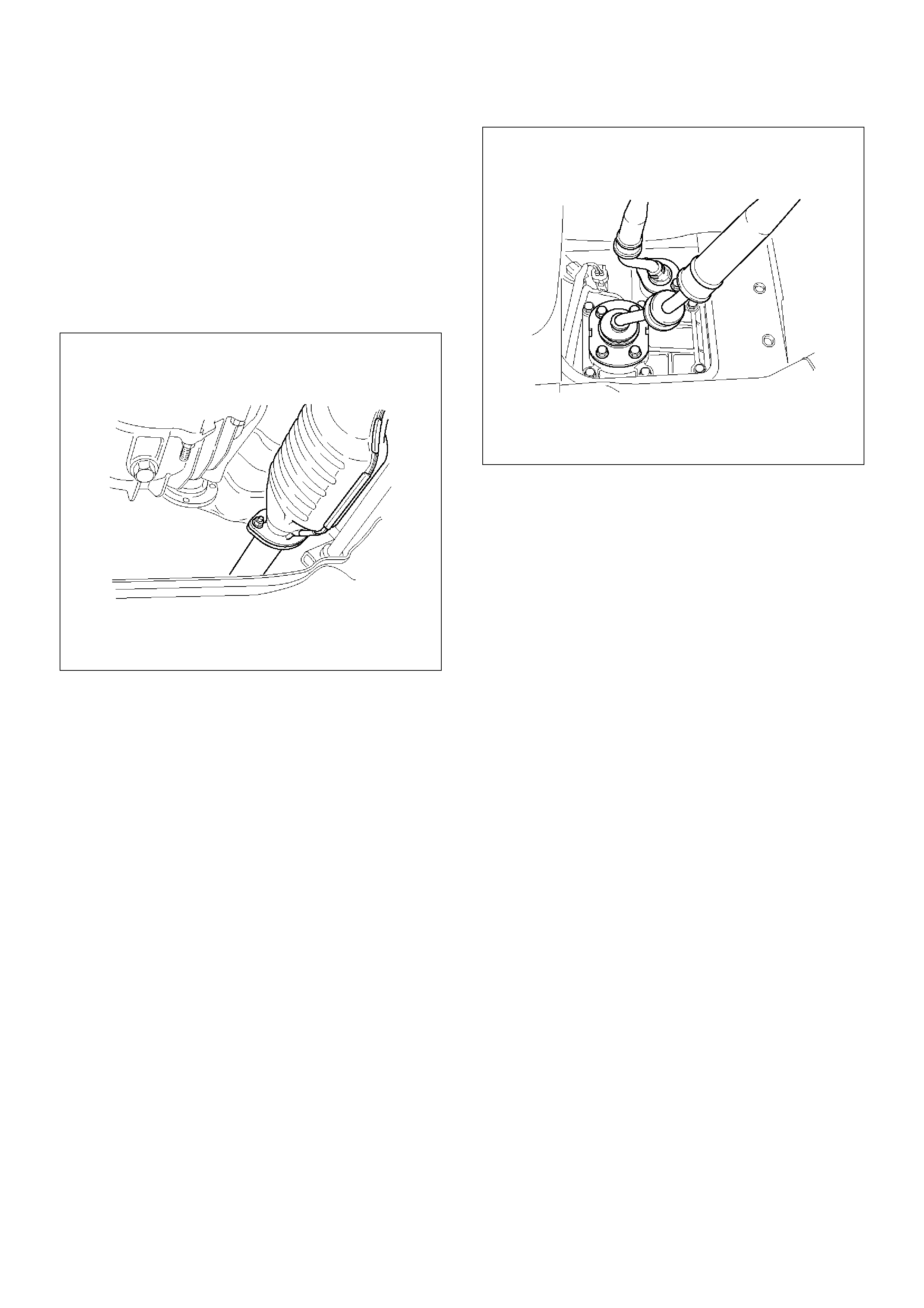
9. Remove the rear propeller shaft.
NOTE: Apply alignment marks on the flange at the both
front and rear side.
(4JX1)
401RW060
10. Remove the front propeller shaft.
NOTE: Apply alignment marks on the flange at both the
front and rear sides.
401RS003
11. Disconnect two oxygen sensor connectors from the
transmission harness (6VE1).
12. Remove the front and 3 way exhaust pipe (6VE1).
Remove the exhaust pipe with catalytic converter
(4JX1).
(4JX1)
150RW041
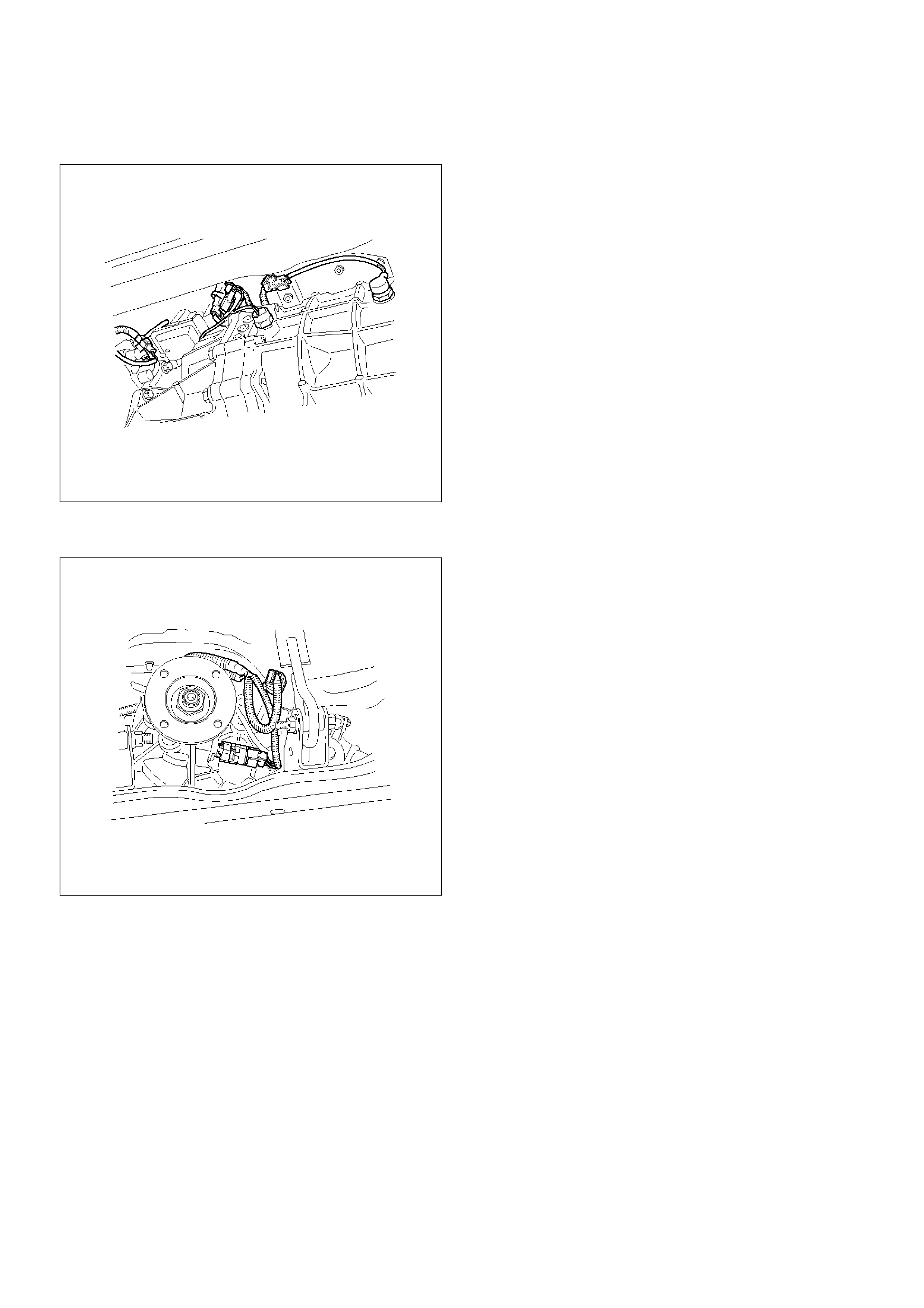
13. Disconnect the backup lamp switch, 4WD indicator
switch and 1–2 indicator switch harness connectors.
826RW023
14. Disconnect the speedometer sensor and 2WD-4WD
actuator harness connectors.
826RW024
15. Remove four fuel pipe bracket from the
transmission case (6VE1).
141RW024
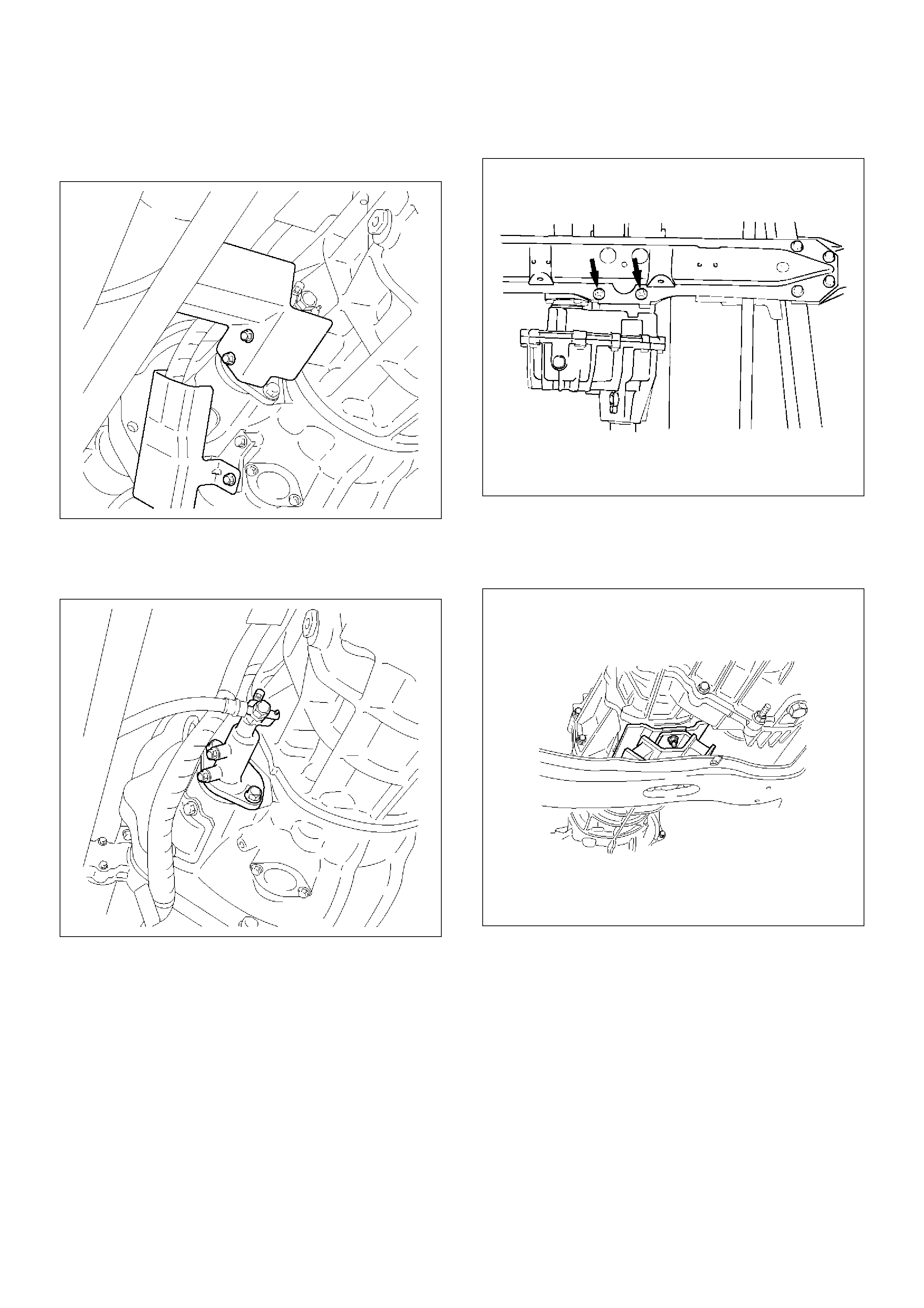
16. Remove the slave cylinder heat protector.
17. Remove the harness heat protector (6VE1).
(6VE1)
225RW006
18. Remove two transmission harness clamps and
bracket (6VE1).
19. Remove the slave cylinder.
206RW002
20. Remove the two dust cover from transmission case.
21. Support the transfer case with a jack.
22. Remove two engine rear mount nuts.
(6VE1)
022RT002
23. Remove third crossmember (6VE1).
24. Remove third crossmember with rear mount rubber
(4JX1).
(4JX1)
022RW013
25. Remove two engine rear mount bolts (6VE1).
26. Remove the rear mount from the transmission
(6VE1).
27. Remove three flywheel under cover (6VE1).
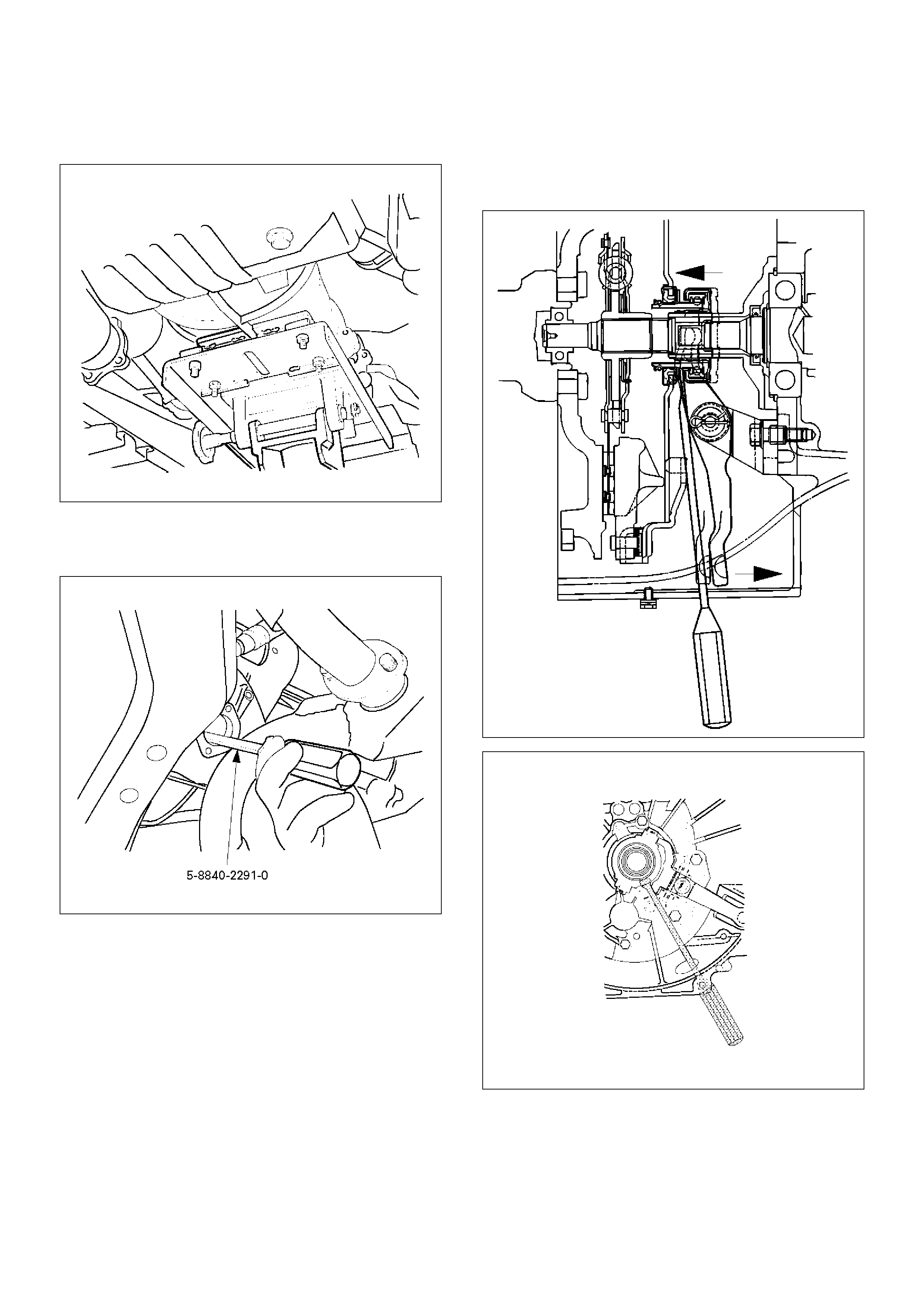
28. Support the transmission with a transmission jack
and then remove jack from the transfer case side.
220RS001
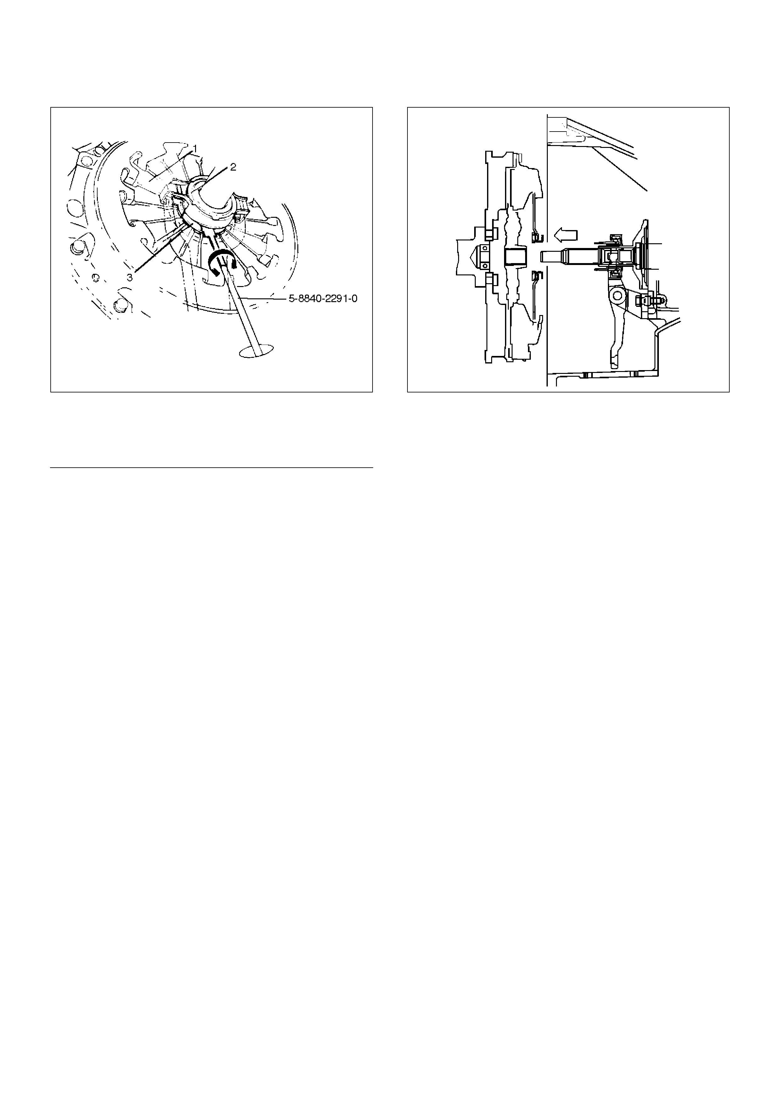
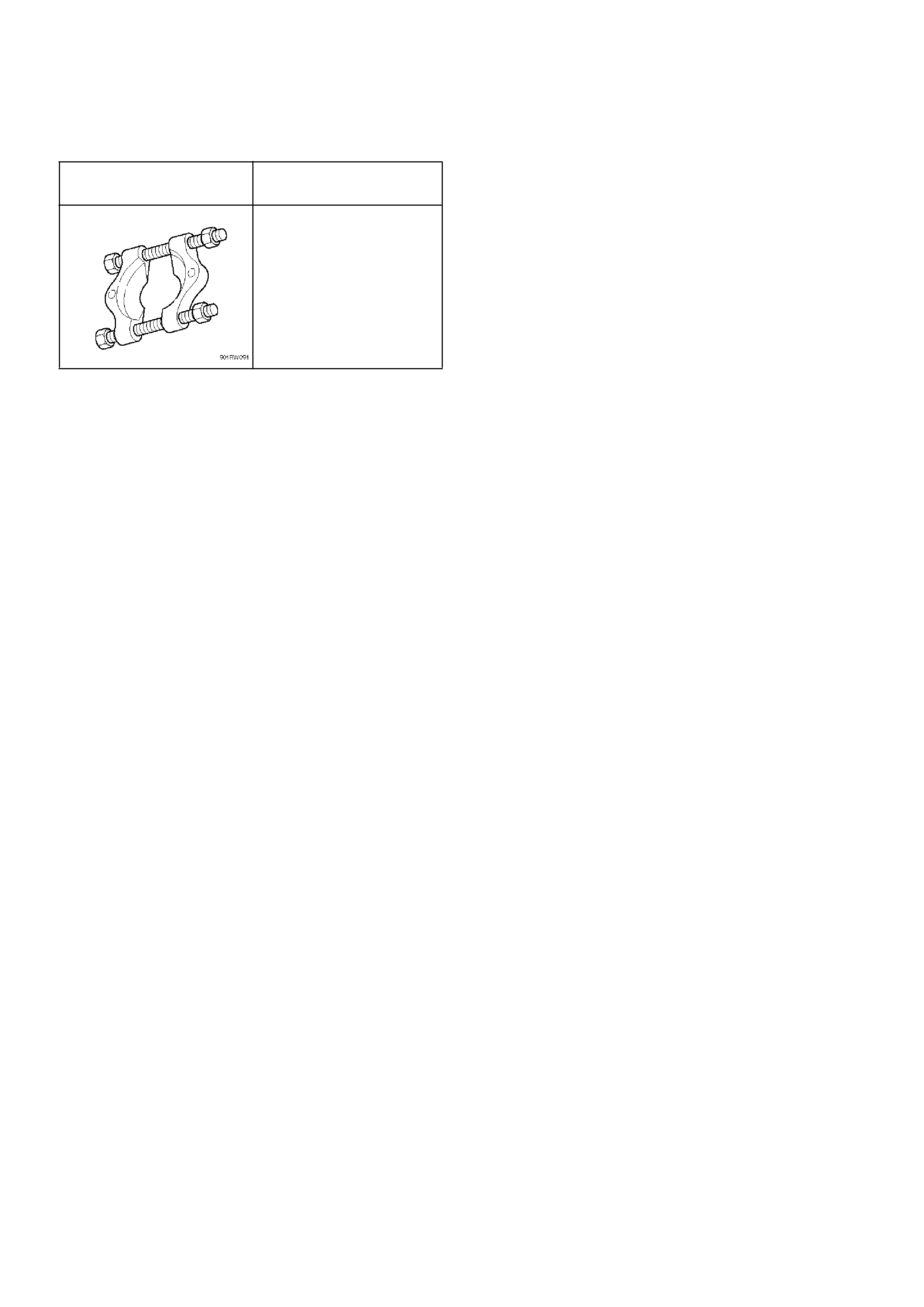
29. Use the clutch release bearing remover 5–8840–
2291–0 (J–39207) to disconnect the clutch release
bearing from the clutch pressure plate.
220RW109
Release bearing disconnection
1. Pull the shift fork toward the transmission to
press the clutch release bearing against the
clutch.
2. Insert the clutch release bearing remover
between the wedge collar and the release
bearing.
3. Turn the remover to separate the release
bearing.
NOTE: Be sure not to insert the remover between the
wedge collar and the clutch.
220RW063
220RW064
220RW119
EndOFCallout
30.Remove the transmission retaining nuts and bolts.
31.Remove the transmission assembly with transfer
case from the vehicle.
NOTE: Remove the transfer case from the
transmission assembly if the transmission disassembly
required.
Refer to Transfer Case in Drive Line/Axle section.
Installation
1. Apply a thin coat of molybdenum disulfide grease to
the top gear shaft spline.
2. Slowly operate the transmission jack until the front
of transmission is aligned with the rear of the
engine.
The slope of the engine and the transmission must
be the same.
3. Align the top gear shaft spline with the clutch driven
plate spline.
220RS005
4. Install the transmission to the engine.
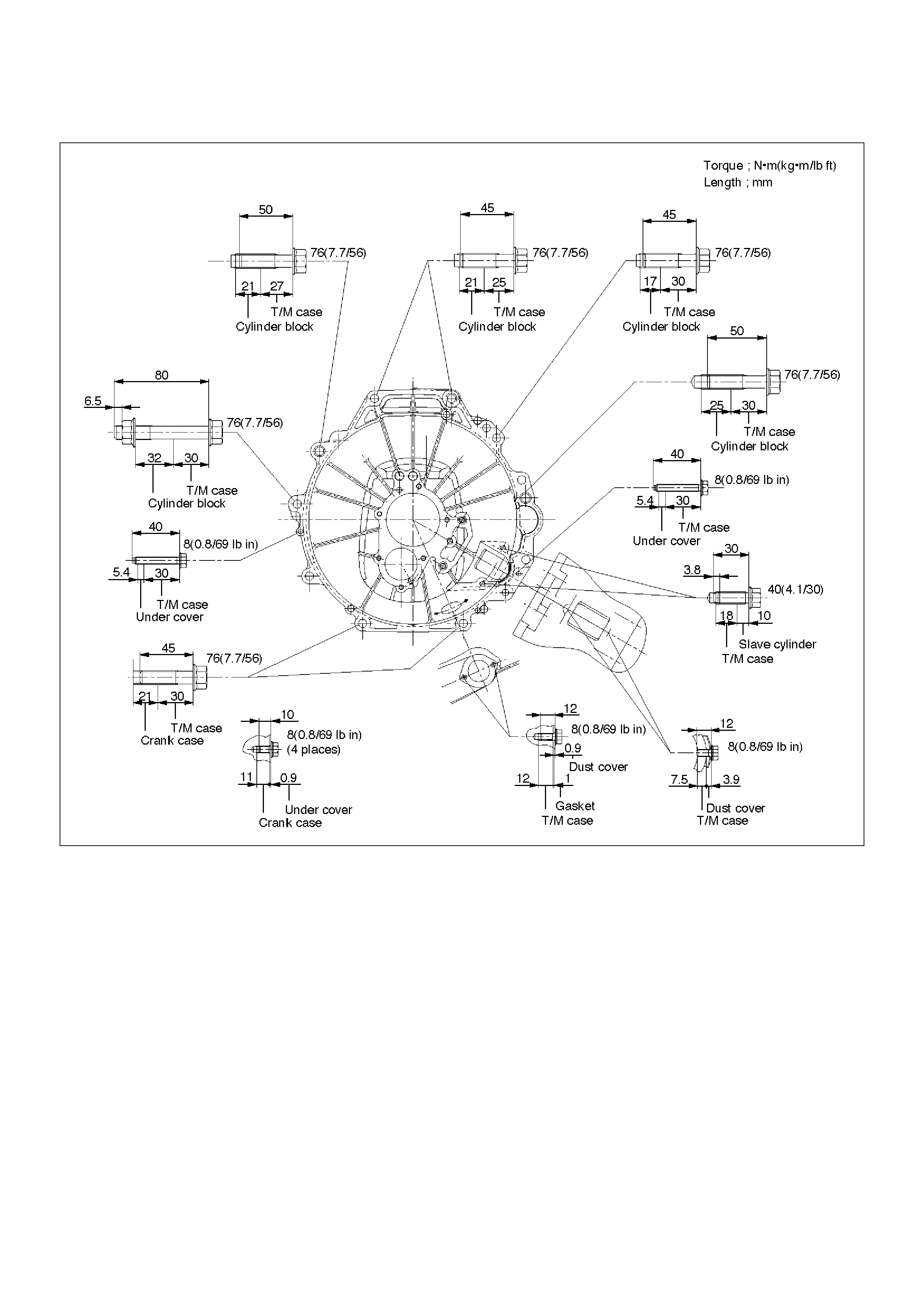
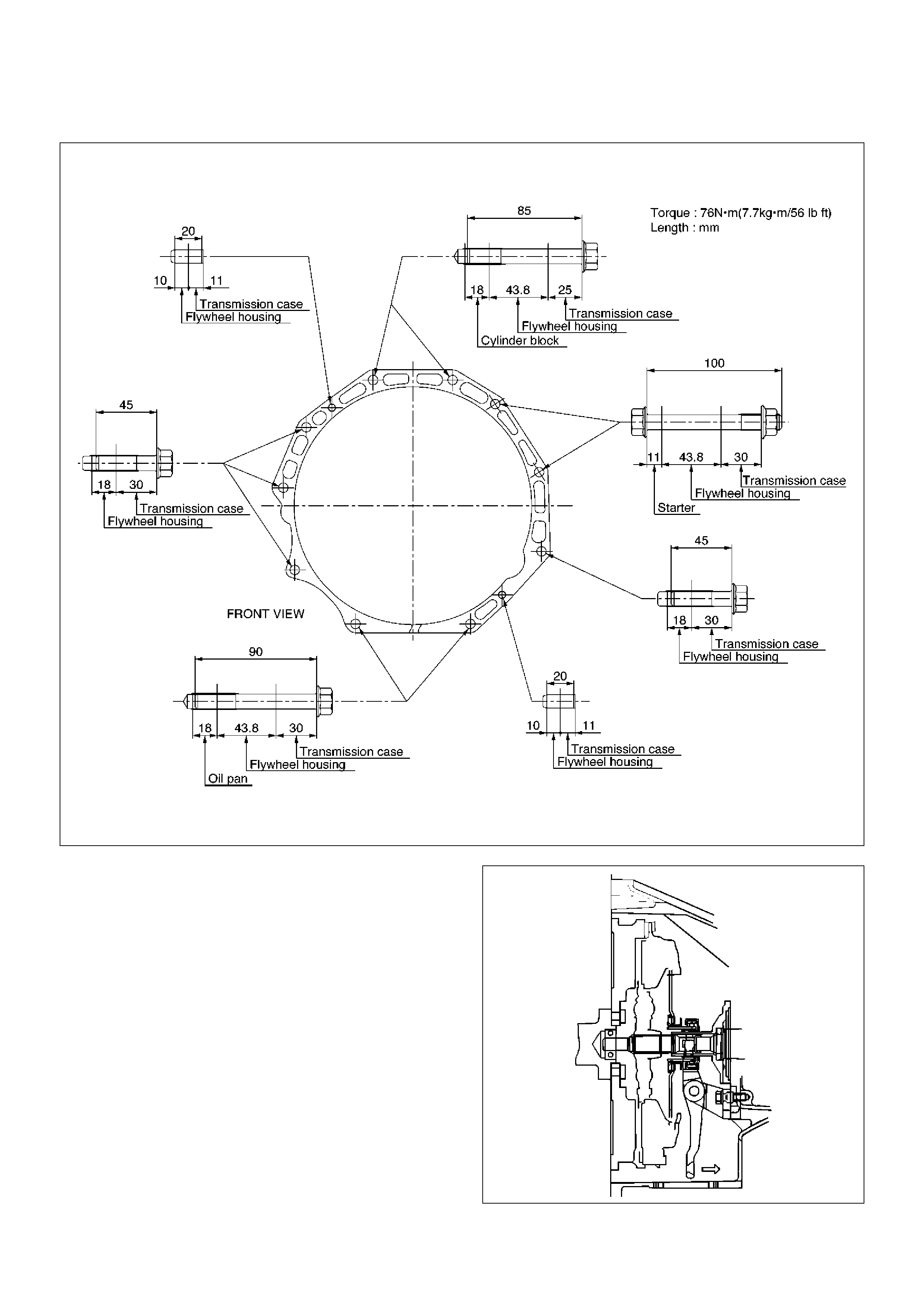
Tighten the transmission retaining nuts and bolts.
Legend
(1) Pressure Plate Assembly
(2) Release Bearing
(3) Wedge Collar
(6VE1)
225RW019
(4JX1)
225RW020
5. Apply a force of about 113N(26Ib) to the tip of the
shift fork in the direction of the transmission to
engage the clutch pressure plate and release
bearing.
NOTE: A clicking sound is heard when the release
bearing and the tip of the diaphragm spring engage
each other.
Check to see if they are securely engaged by pushing
the tip of the shift fork toward the engine while applying
a force of about 25 N (5.5 lb). If the shift fork will not
move, then they are securely engaged.
220RS006
6. Install three flywheel under cover (6VE1).
7. Install the engine rear mount to the transmission
case and tighten the fixing bolts specified torque
(6VE1).
Torque: 41 N·m (4.2kg·m/30 Ibft)
8. Install the third crossmember to the frame and
tighten the fixing bolts specified torque.
Torque: 50 N·m (5.1kg·m/37 Ibft)
9. Tighten the engine rear mount nuts specified torque.
Torque: 50 N·m (5.1kg·m/37 Ibft)
10. Remove the transmission jack.
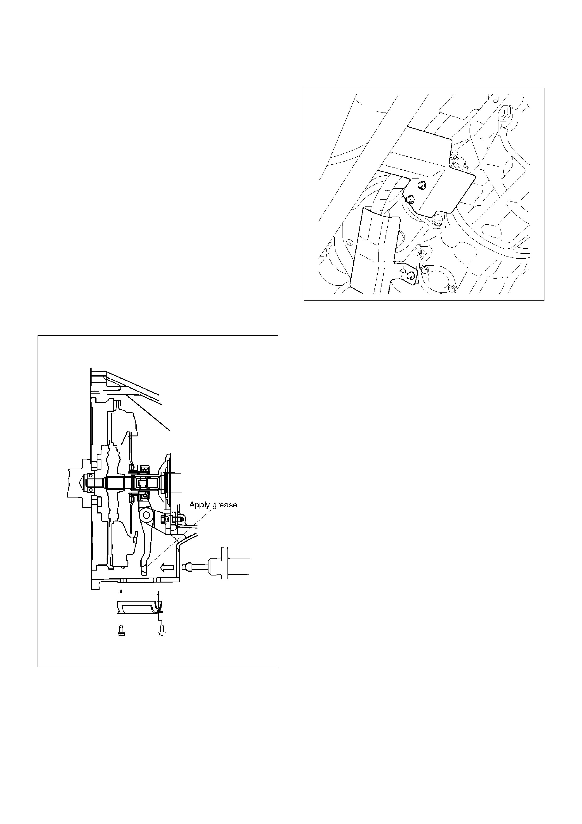
11. Apply the grease to top hole portion of the shift fork.
12. Install the slave cylinder and tighten the fixing bolts
specified torque.
Torque: 43 N·m (4.4kg·m/32 Ibft)
13. Install the clutch dust cover to the clutch housing
and tighten the fixing bolts specified torque.
Torque: 8 N·m (0.8kg·m/69Ibin)
220RS007
14. Install the slave cylinder heat protector to the slave
cylinder.
15. Install bracket and two transmission harness clamps
to the transmission case (6VE1).
16. Install harness heat protector (6VE1).
(6VE1)
225RW006
17. Install four fuel pipe bracket (6VE1).
141RW024
18. Connect the speedometer sensor and 2WD–4WD
actuator harness connector.
826RW024
19. Connect the backup lamp switch, 4WD indicator
switch, and 1-2 indicator switch harness connectors.
826RW023
20. Install the front and 3 way exhaust pipe (6VE1).
Install the exhaust pipe with catalytic converter
(4JX1).
Torque:
Exhaust pipe to exhaust manifold:
67 N·m (6.8kg·m/49 Ibft)
Exhaust pipe flange bolt:
43 N·m (4.4kg·m/32 Ibft)
(4JX1)
150RW041
21. Connect two oxygen sensor connectors to the
transmission harness (6VE1).
22. Install the front propeller shaft and tighten the fixing
bolts and nuts specified torque.
Torque: 63 N·m (6.4 kg·m/46Ib ft)
23. Install the rear propeller shaft and tighten the fixing
bolts and nuts specified torque.
Torque: 63 N·m (6.4 kg·m/46Ib ft)
24. Install transfer protector and tighten the fixing bolts
specified torque.
Torque: 37 N·m (3.8 kg·m/27Ib ft)
25. Install the transmission control lever and transfer
control lever.
235RW014
26. Install the grommet assembly.
27. Install the front console assembly.
28. Install the gear control lever knob.
29. Connect battery ground cable.
30. Install engine hood.
Rear Oil Seal (Transfer Adapter)
Removal
1.Remove the transfer case assembly from the
vehicle.
Refer to Transfer Case in Drive Line/Axle section.
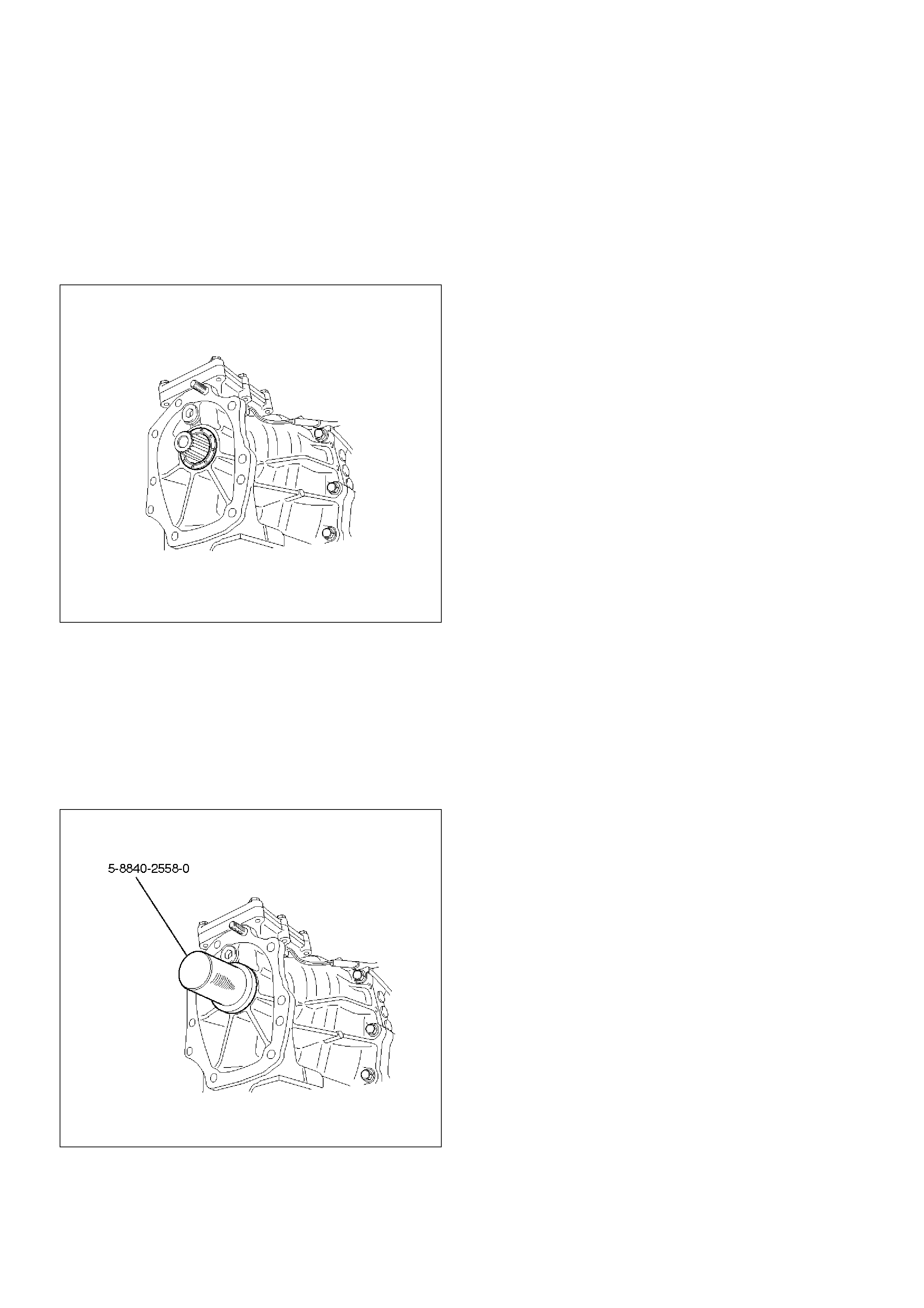
2.Remove the rear oil seal from the transfer adapter.
220RW090
Installation
1.Use 5–8840–2558–0 (J–42802) transfer adapter oil
seal installer, and install the rear oil seal to the
transfer adapter.
2.Apply grease to the oil seal lip.
3.Install the transfer case assembly to the vehicle.
Refer to Transfer Case in Drive Line/Axle section.
220RW115
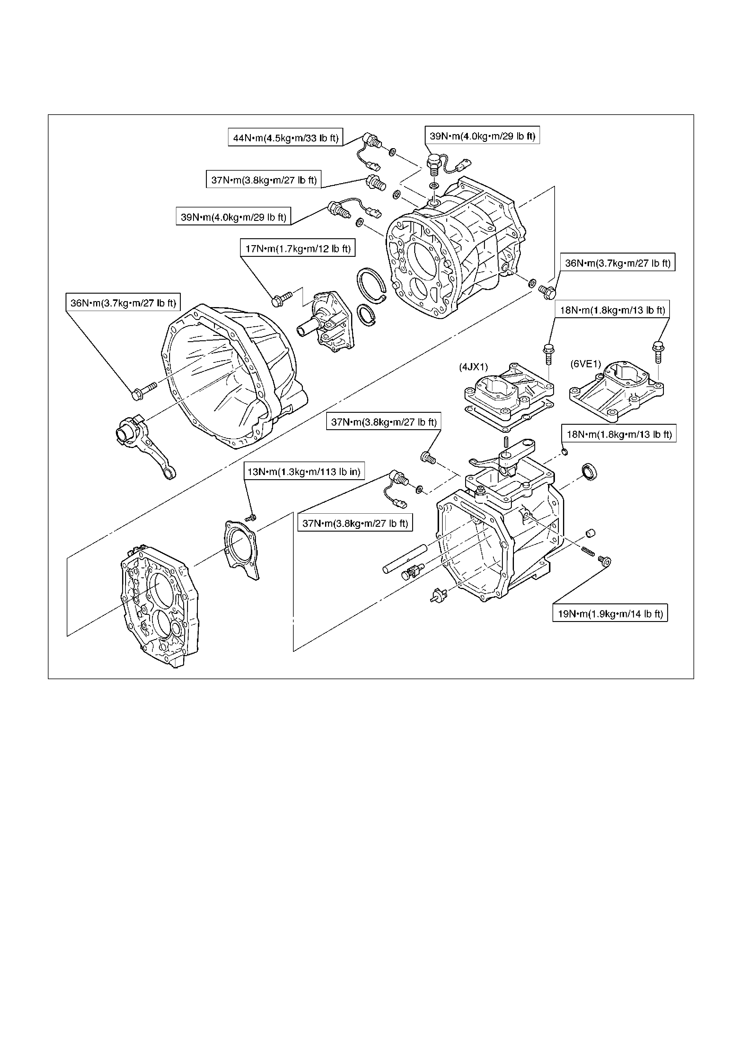
Transmission (AR-5)
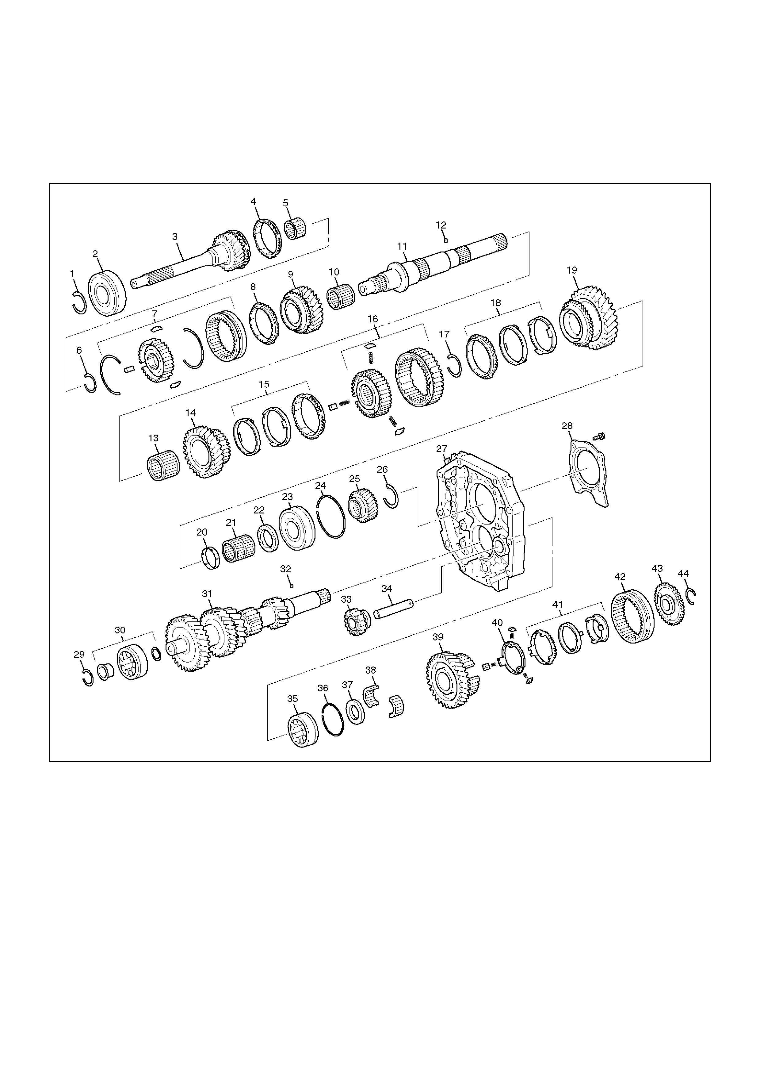
Disassembled View
226RW182
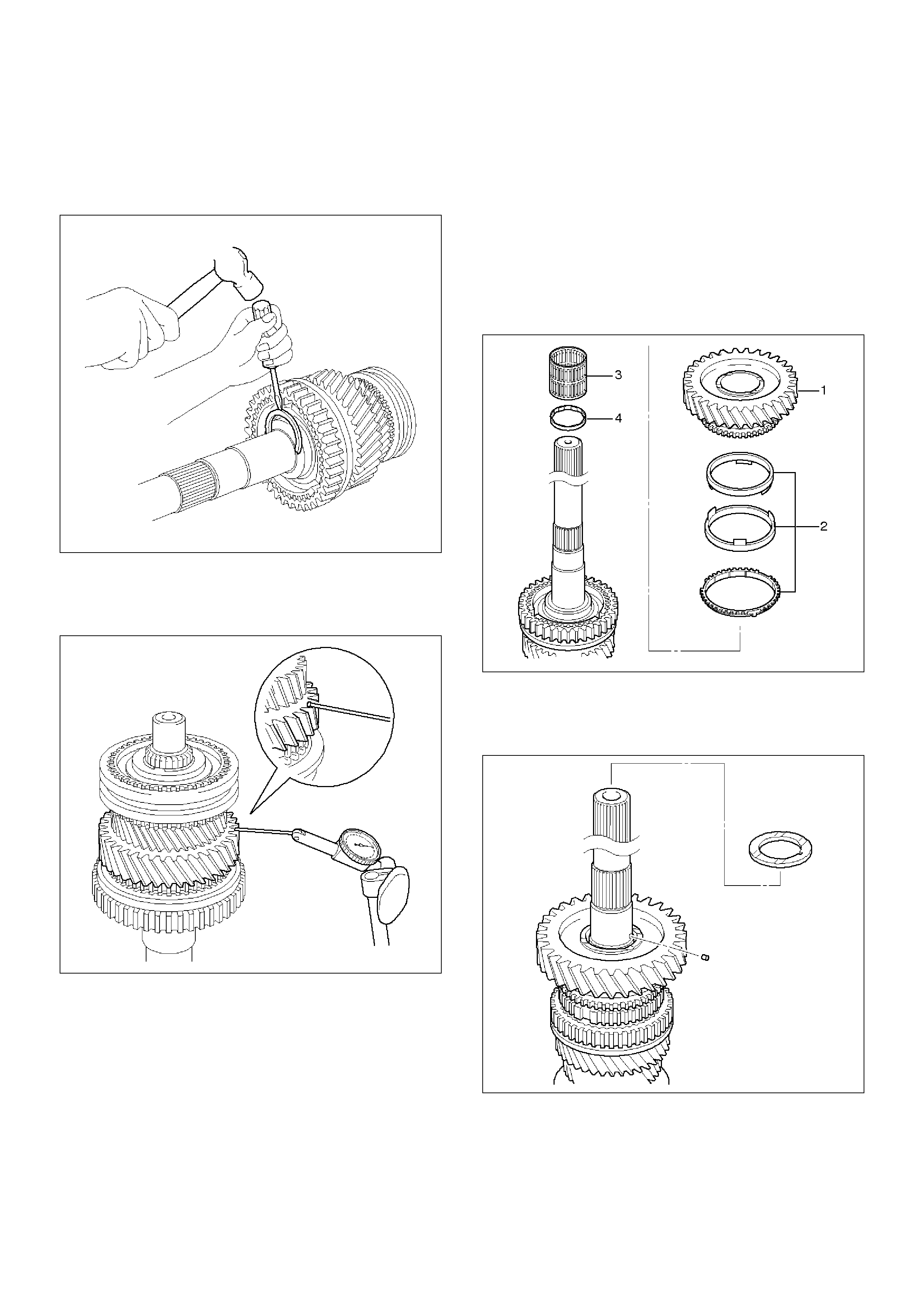
Legend
(1) Snap Ring
(2) Bearing
(3) Top Gear Shaft
(4) Block Ring
(5) Roller Bearing
(6) Snap Ring
(7) Clutch Hub No.2 Assembly
(8) 3rd Block Ring
(9) 3rd Gear
(10) 3rd Gear Needle Roller Bearing
(11) Mainshaft
(12) Thrust Washer Pin
(13) 2nd Gear Needle Roller Bearing
(14) 2nd Gear
(15) Synchronizer Assembly
(16) Clutch Hub No.1 Assembly
(17) Snap Ring
(18) Synchronizer Assembly
(19) 1st Gear
(20) 1st Gear Bearing Spacer
(21) 1st Gear Needle Roller Bearing
(22) 1st Gear Thrust Washer
(23) Mainshaft Bearing
(24) Snap Ring
(25) 5th Gear
(26) Snap Ring
(27) Intermediate Plate
(28) Bearing Retainer
(29) Snap Ring
EndOFCallout
226RW00001
EndOFCallout
(30) Front Bearing Assembly
(31) Counter Gear Shaft
(32) Thrust Washer Pin
(33) Reverse Idle Gear
(34) Reverse Idle Gear Shaft
(35) Counter Gear Shaft Center Bearing
(36) Snap Ring
(37) Thrust Washer
(38) Roller Bearing
(39) Counter 5th Gear
(40) Reverse Block Ring
(41) Synchronizer Assembly
(42) Hub Sleeve No.3
(43) 5th Gear Spline Piece
(44) Snap Ring
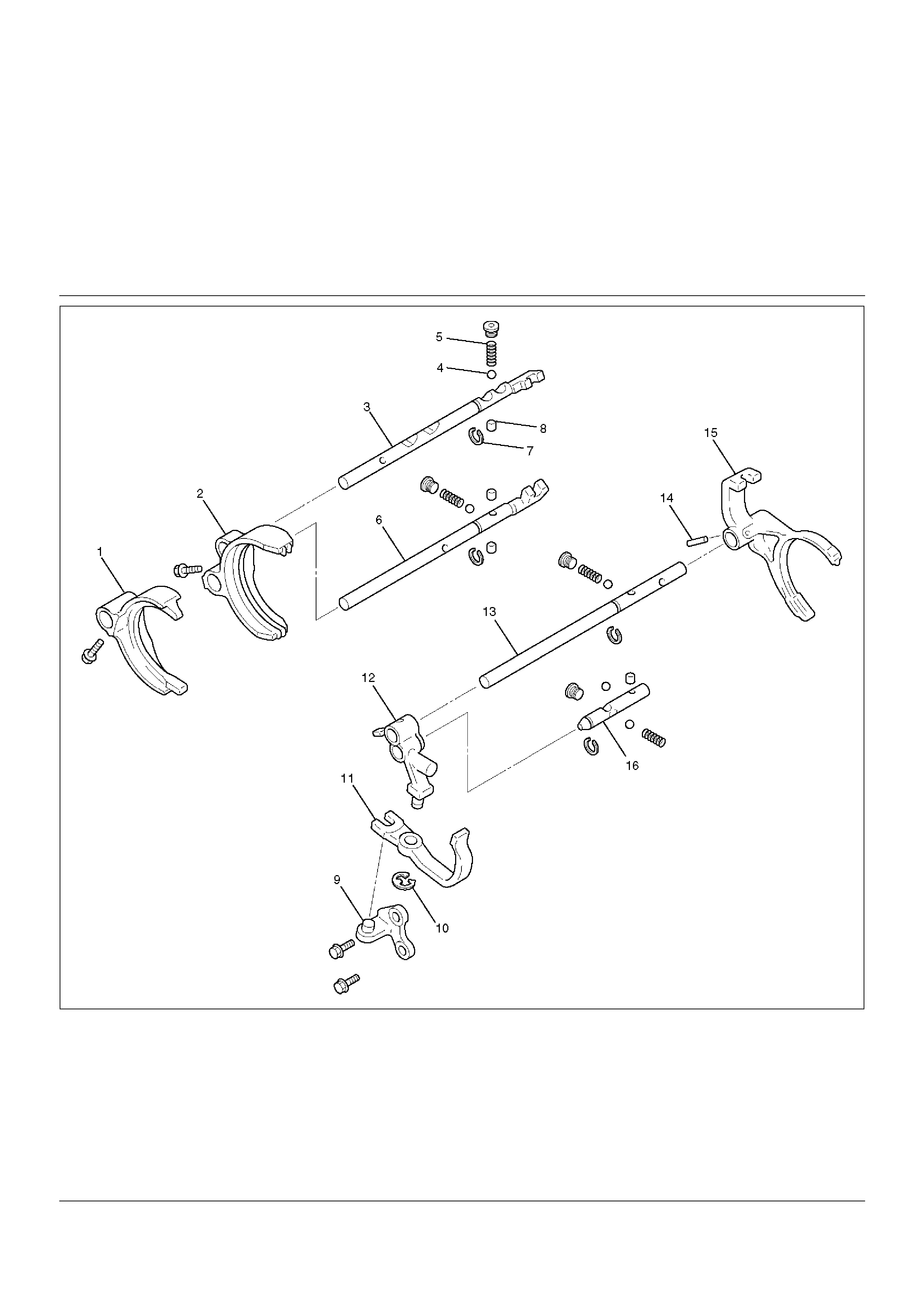
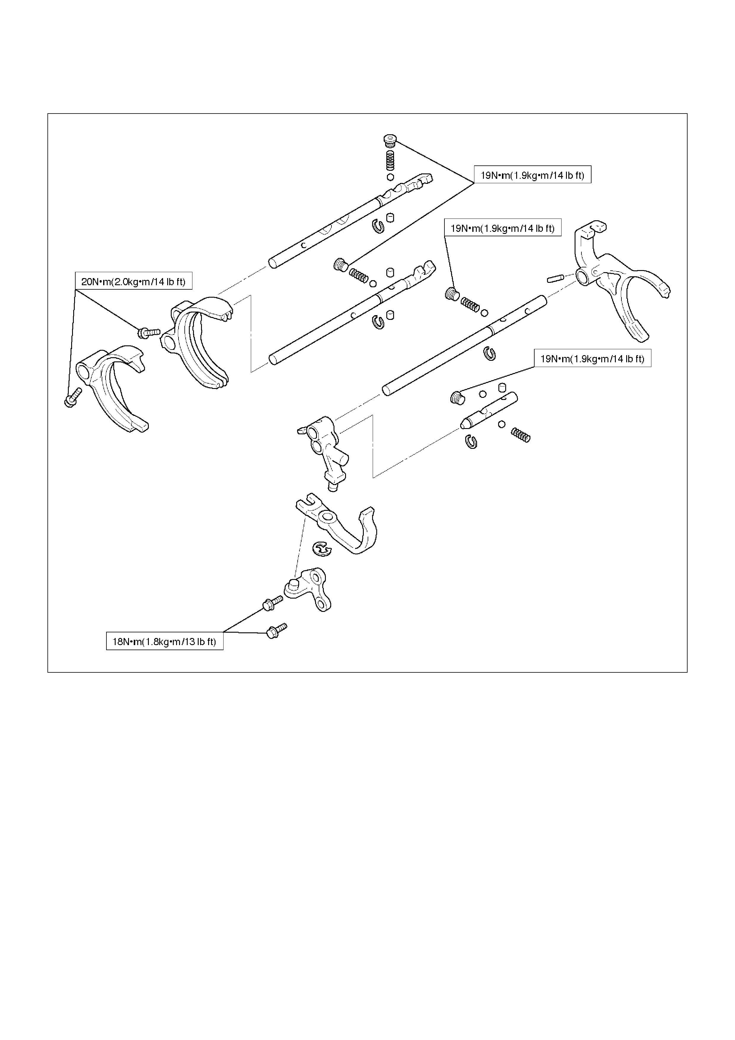
Legend
(1) 3rd-4th Shift Arm
(2) 1st-2nd Shift Arm
(3) 3rd-4th Shift Rod
(4) Ball
(5) Spring
(6) 1st-2nd Shift Rod
(7) Snap Ring
(8) Interlock Pin
(9) Reverse Shift Arm Bracket
(10) E–Ring
(11) Reverse Shift Arm No.2
(12) Reverse Shift Arm No.1
(13) 5th Reverse Shift Rod
(14) Spring Pin
(15) 5th Shift Arm
(16) Reverse Shift Rod
220RW095
EndOFCallout
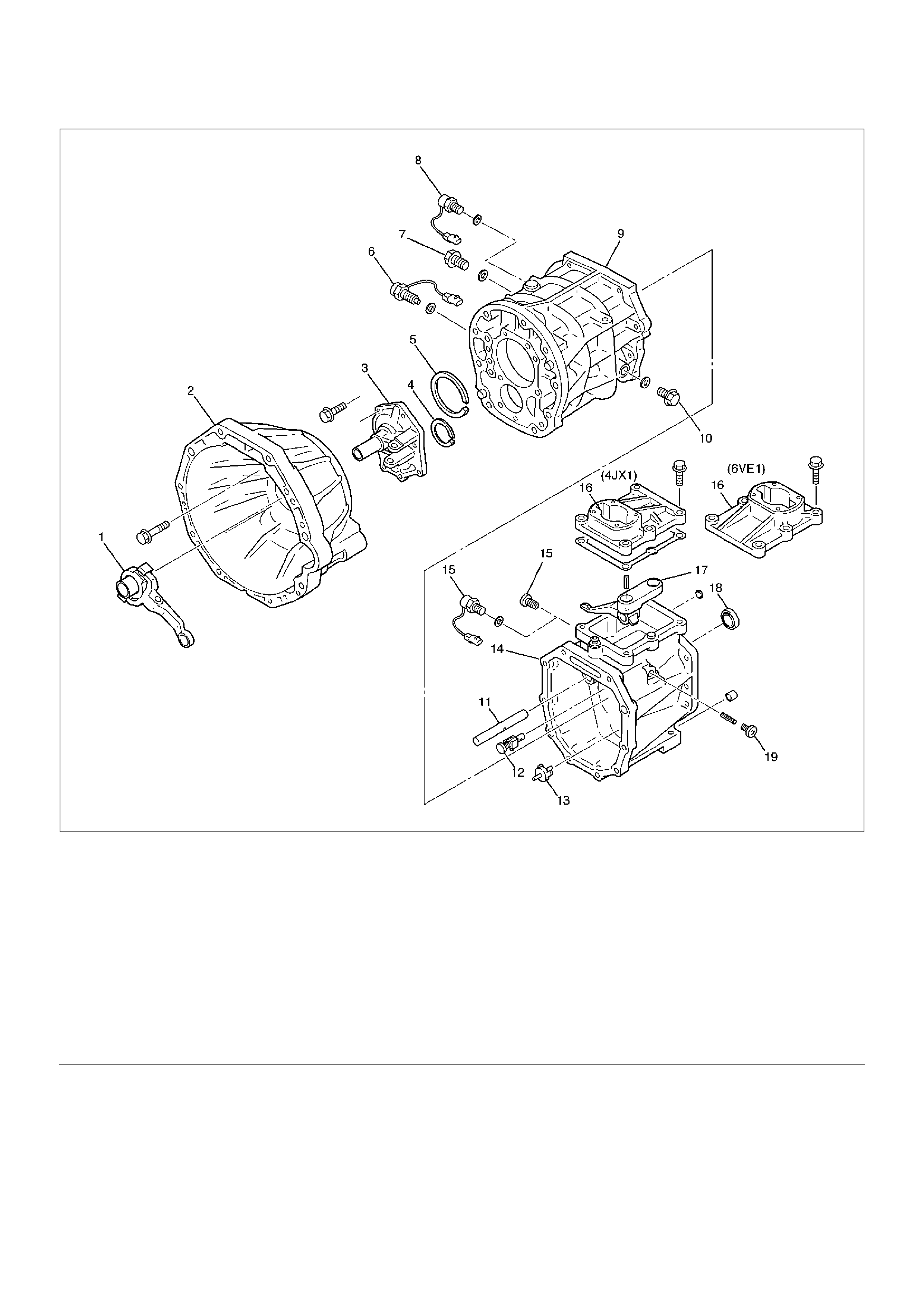
Legend
(1) Release Bearing and Shift Fork
(2) Clutch Housing
(3) Front Cover
(4) Snap Ring
(5) Snap Ring
(6) 1st and 2nd Switch
(7) Drain Plug
(8) Backup Light Switch
(9) Transmission Case
(10) Filler Plug
(11) Gear Control Rod
(12) Reverse Restrict Pin
(13) Oil Receiver Pipe
(14) Transfer Adapter
(15) Plug (6VE1) or Neutral Switch (4JX1)
(16) Gear Control Box
(17) Shift Lever Housing
(18) Oil Seal
(19) Plug
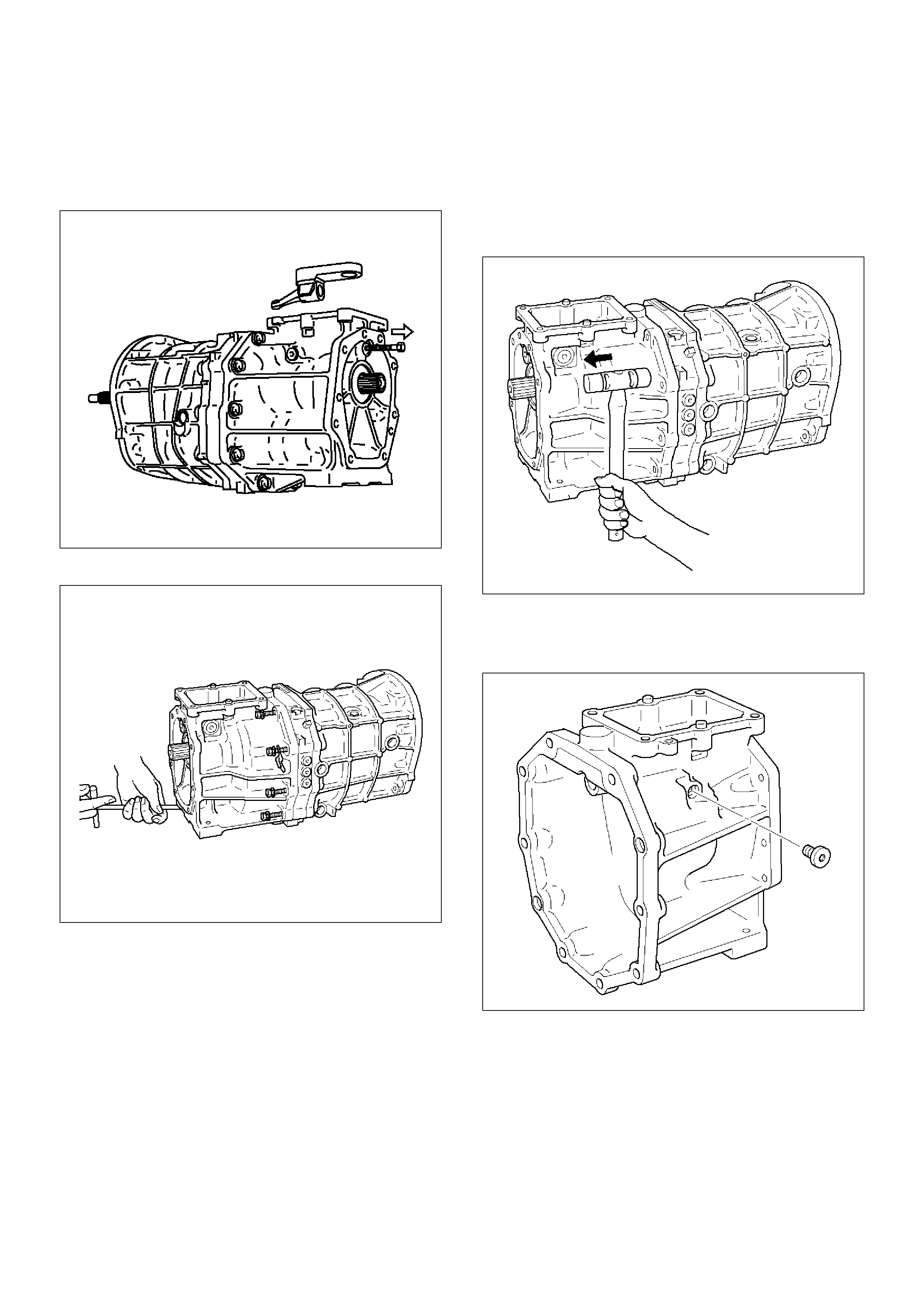
Disassembly
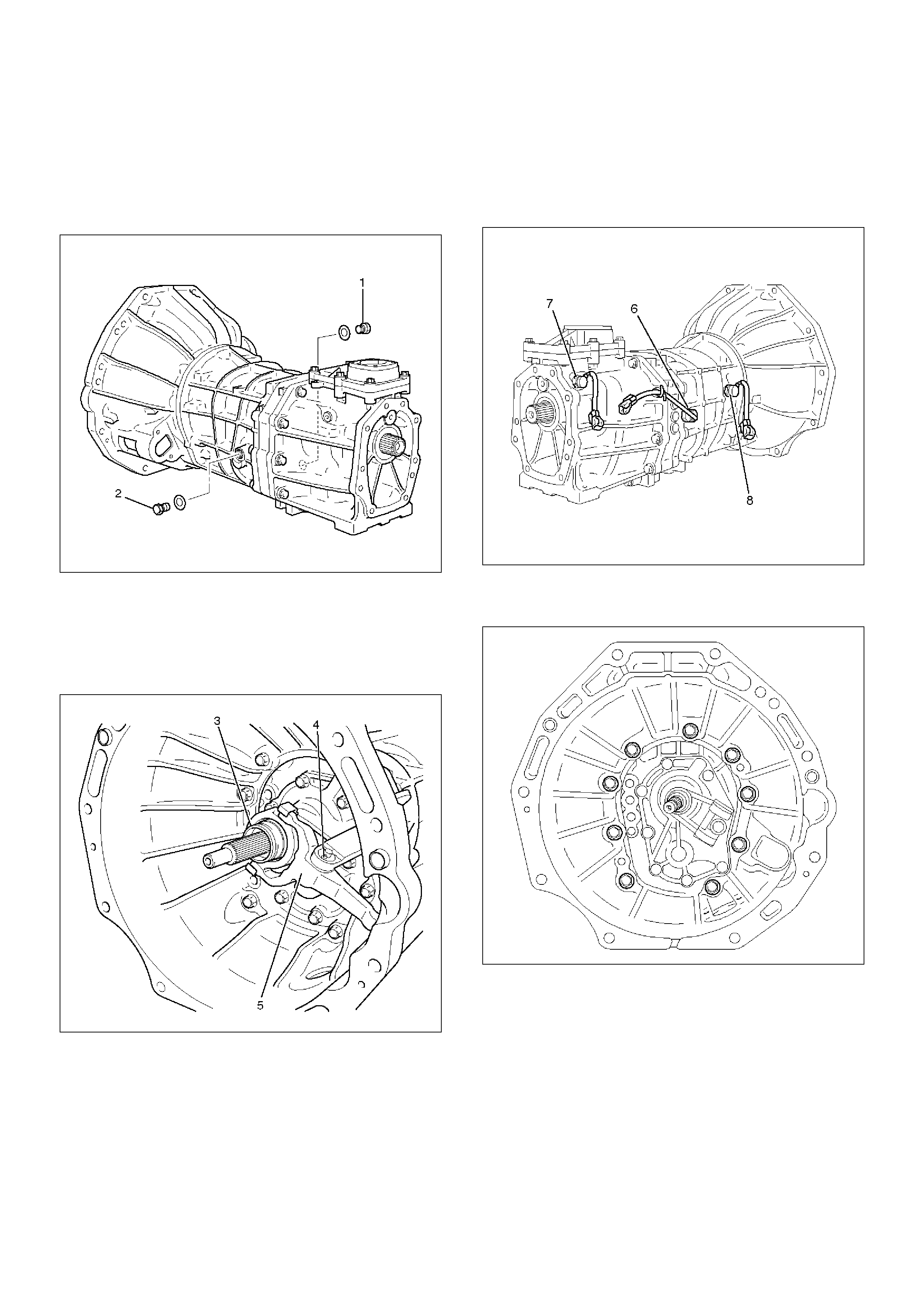
1. Remove the drain plug and filler plug.
1. Remove the drain plug (1) and gasket.
2. Remove the filler plug (2) and gasket.
(6VE1)
220RW007
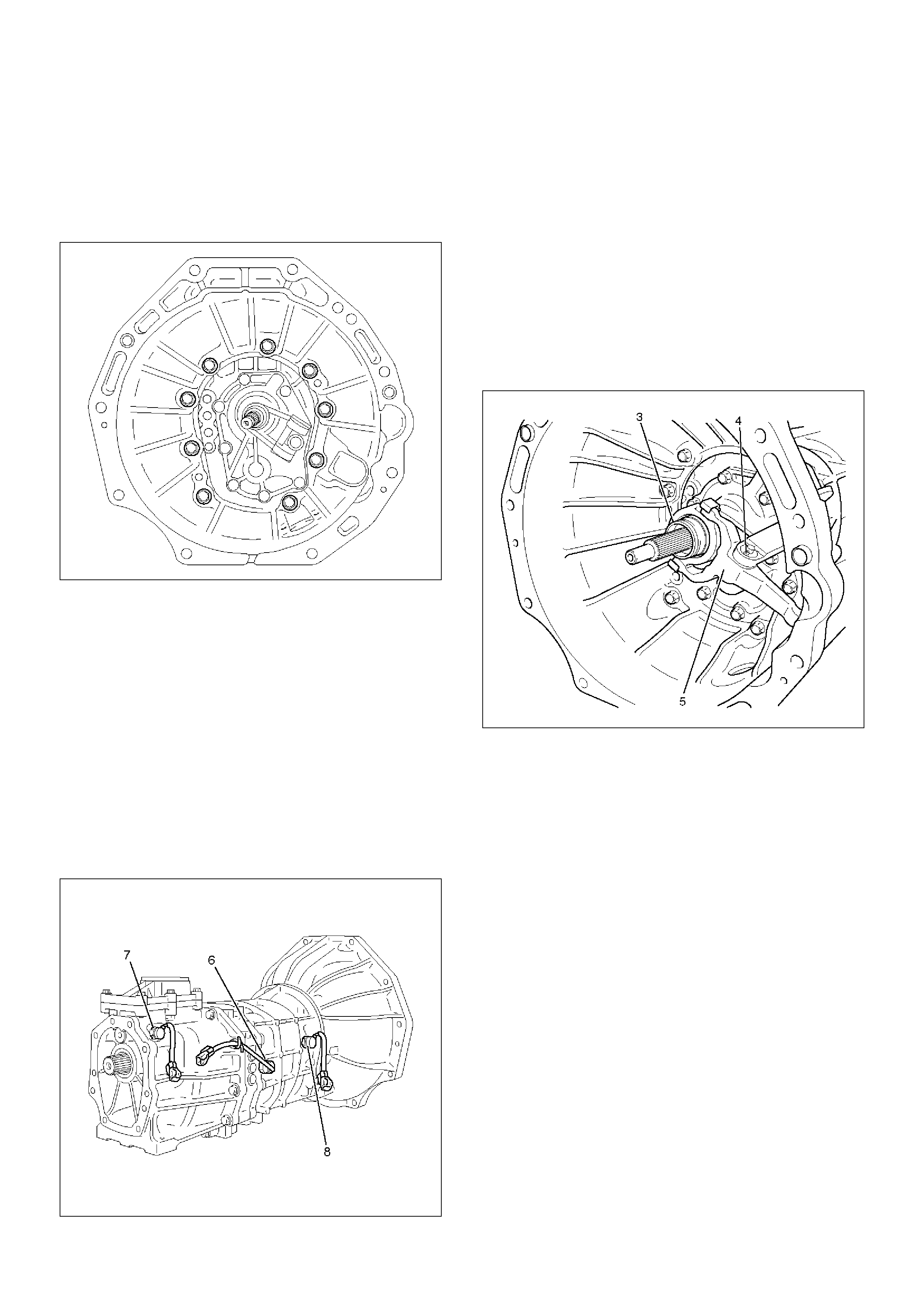
2. Remove the clutch release bearing and shift fork.
1. Remove the clutch release bearing (3) from the
front cover.
2. Remove the split pin (4). Remove the shaft from
the under. Remove the shift fork (5).
220RW086
3. Remove the switch.
1. Remove backup light switch (6) and gasket.
2. Remove neutral switch (7) and gasket (4JX1).
3. Remove 1st and 2nd switch (8) and gasket.
(4JX1)
220RW093
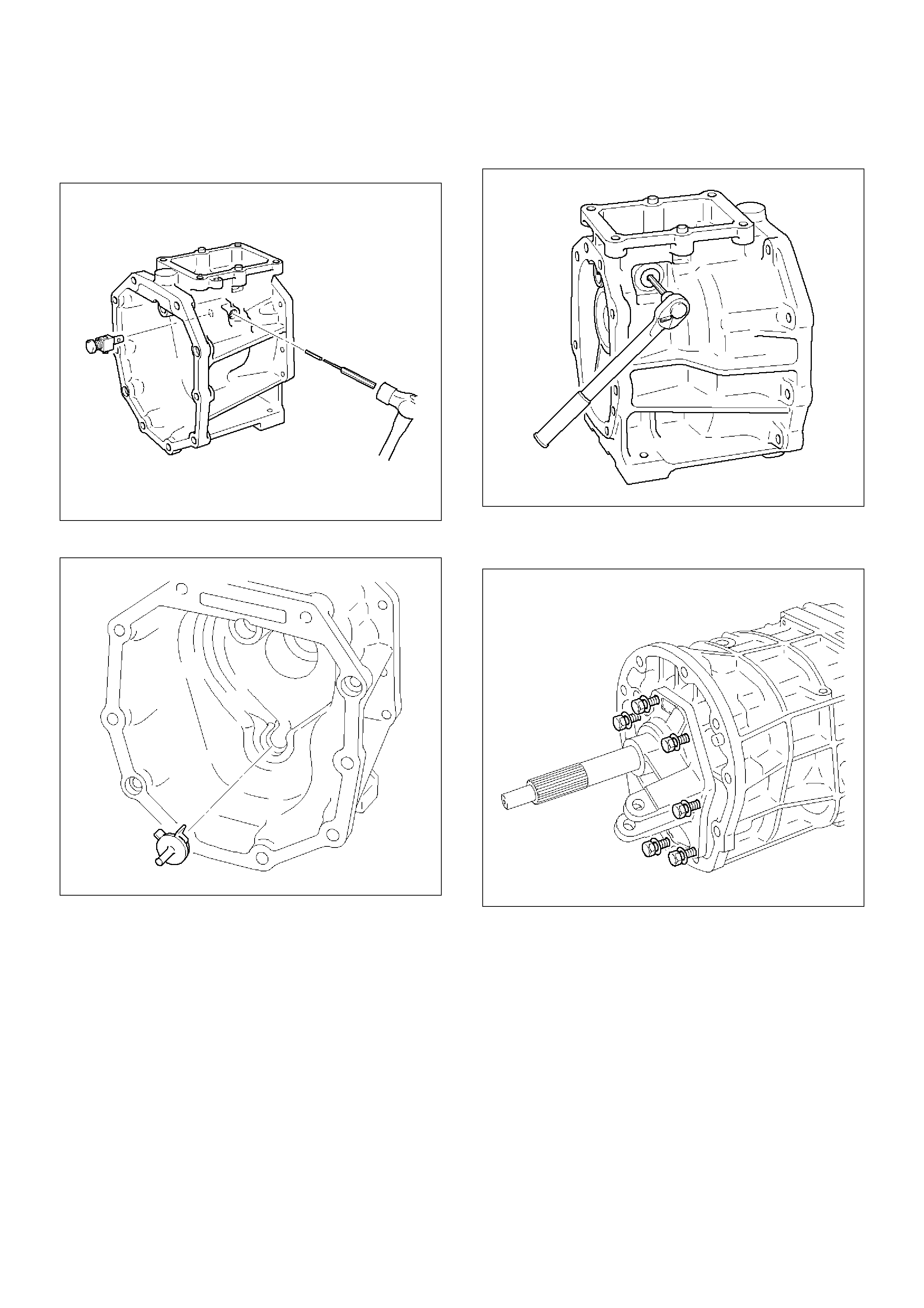
4. Remove the clutch housing.
1. Remove the 9 bolts.
241RW001
2. Using a plastic hammer, carefully tap the clutch
housing.
(6VE1)
220RW008
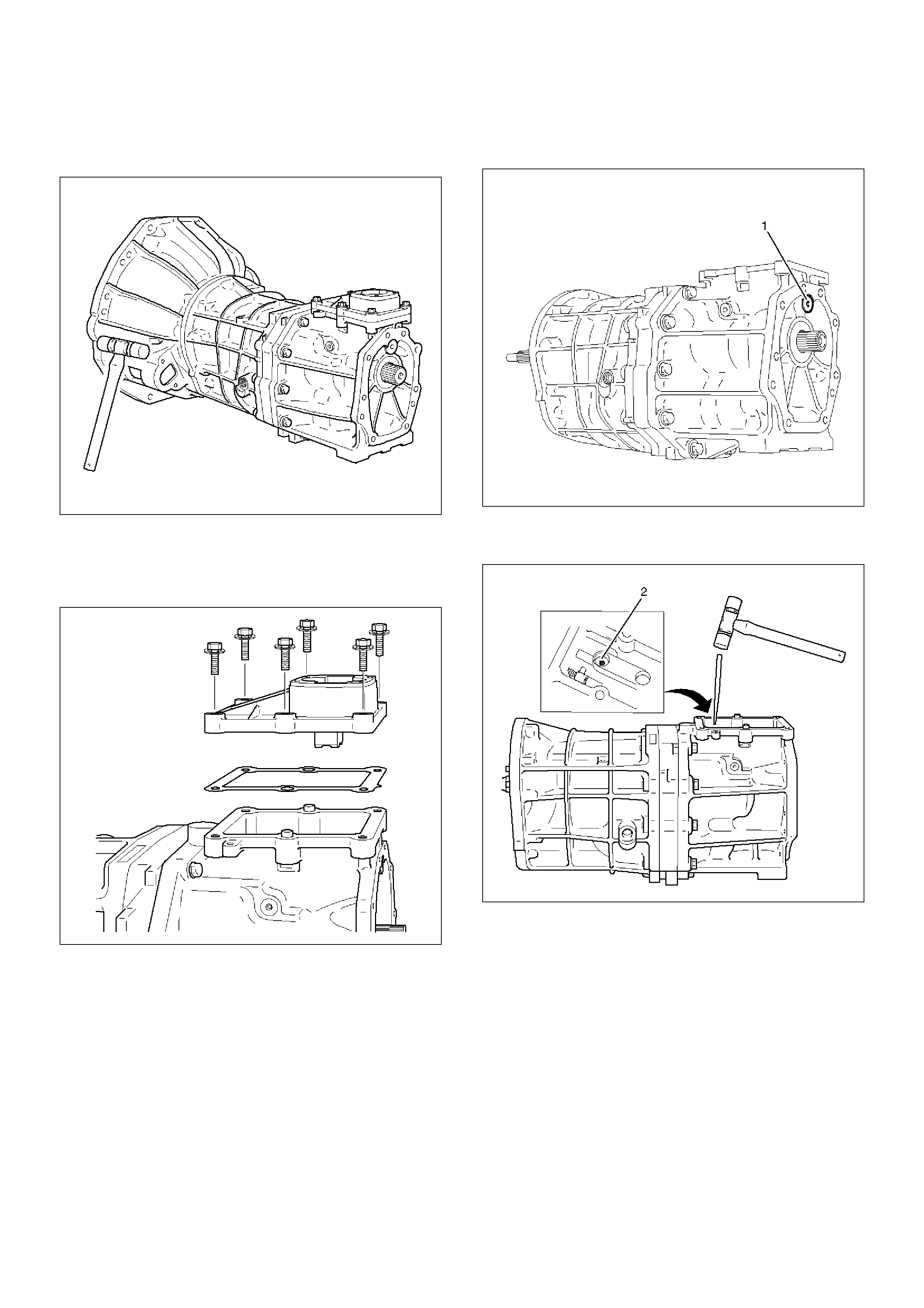
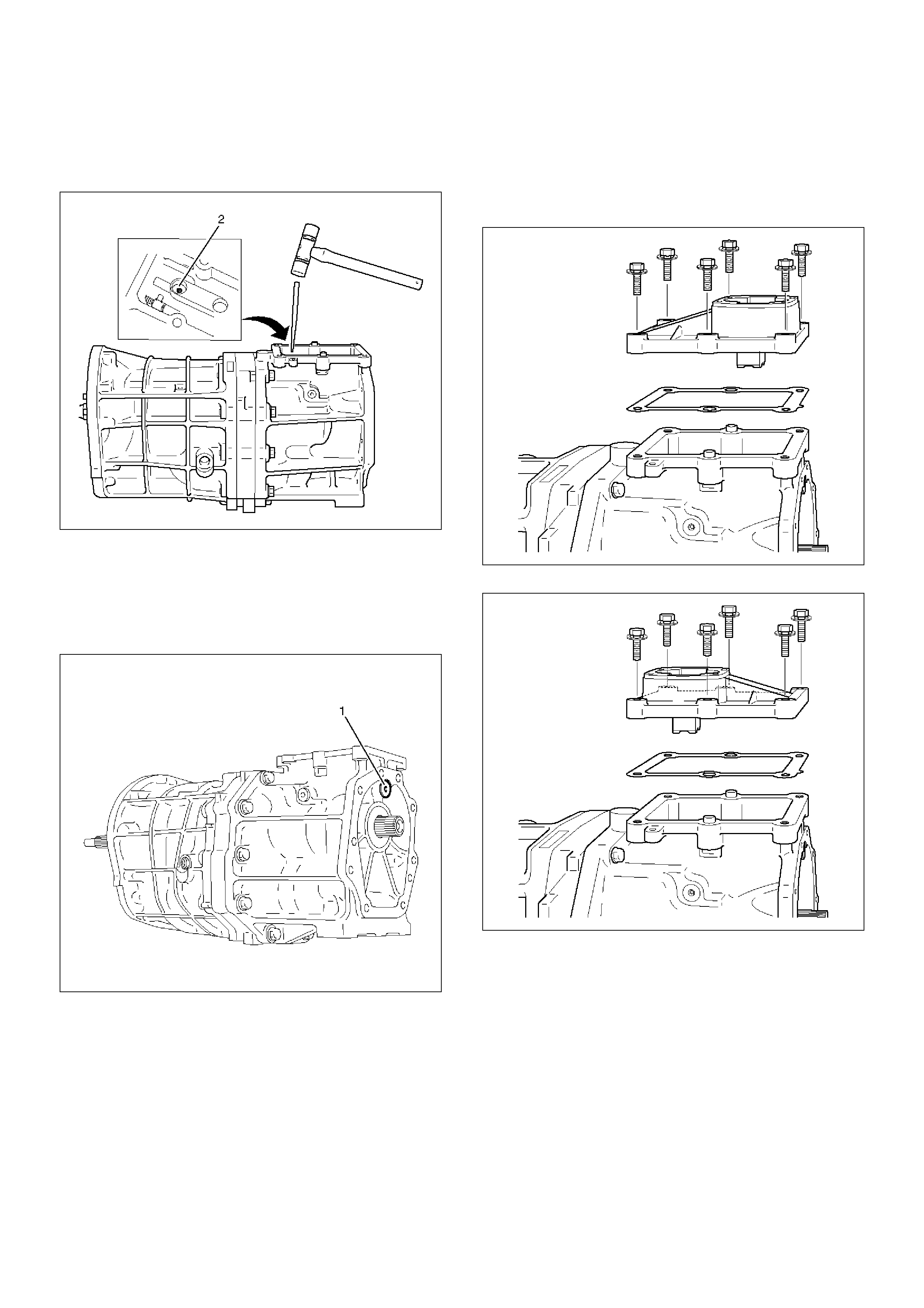
5. Remove gear control box and gasket.
1. Remove the 6 bolts, gear control box and
gasket.
(6VE1)
230RW001
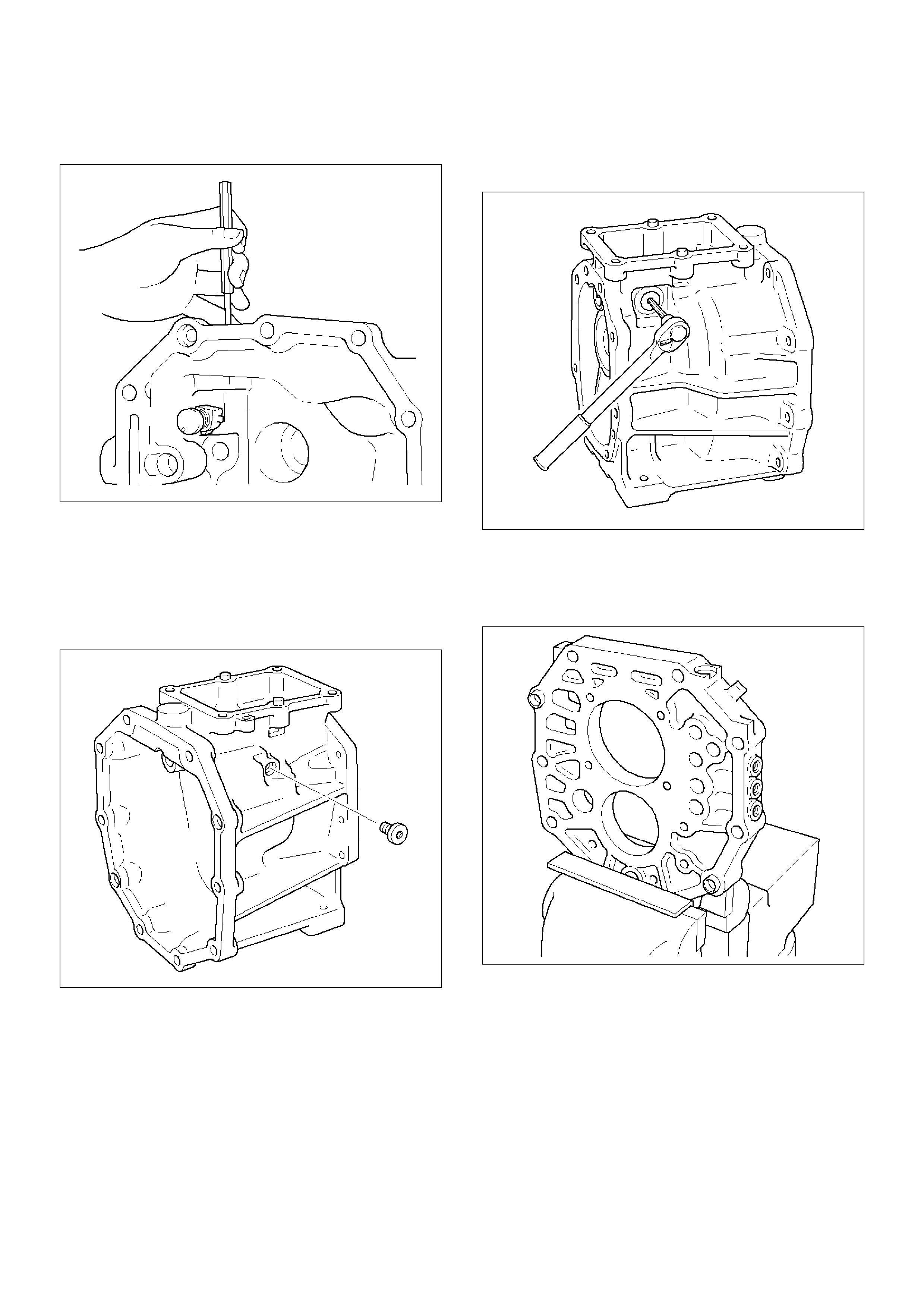
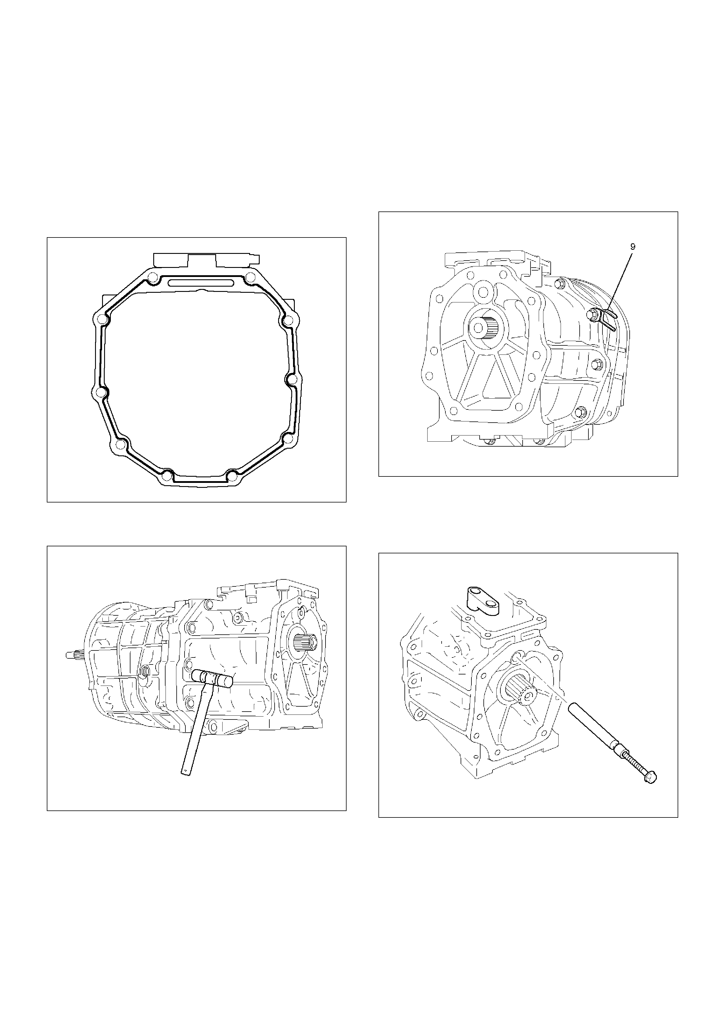
6. Remove transfer adapter.
1. Using a hexagon wrench, remove the plug (1).
220RW010
2. Using a pin punch and hammer, drive out the
slotted spring pin (2).
230RW002
3. Using the M8 ´ 1.25 bolt, remove the gear
control rod and the shift lever hausing.
NOTE: Turn the M8 bolt a few times, before remove the
gear control rod.
220RW098
4. Remove the 10 bolts and clamp.
220RW016
5. Using a plastic hammer, tap the transfer
adapter.
NOTE:
• Be careful not to lose the pin.
• Cover the mainshaft splines with adhesive tape.
This will prevent damage to the oil seal lip.
220RW015
7. Disassemble the transfer adapter assembly.
1. Using a torx socket wrench(T40), remove the
plug.
220RW013
2. Using a pin punch and hammer, drive out the
slotted spring pin. Remove the reverse restrict
pin.
220RW012
3. Remove the oil receiver pipe.
220RW011
4. Remove the oil seal.
5. Using socket hexagon wrench, remove the plug.
220RW014
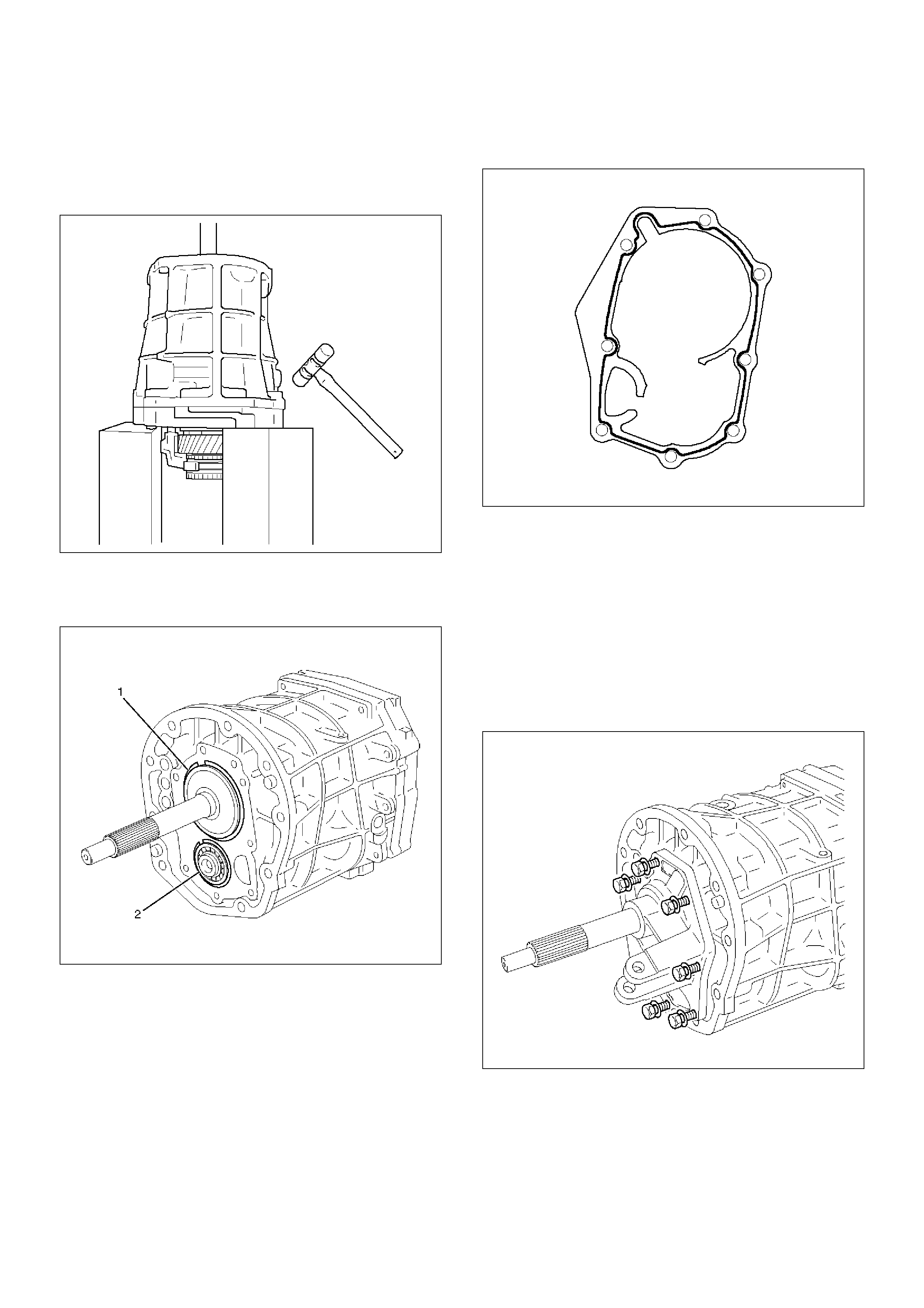
8. Remove the front cover.
1. Remove the 8 bolts.
220RW018
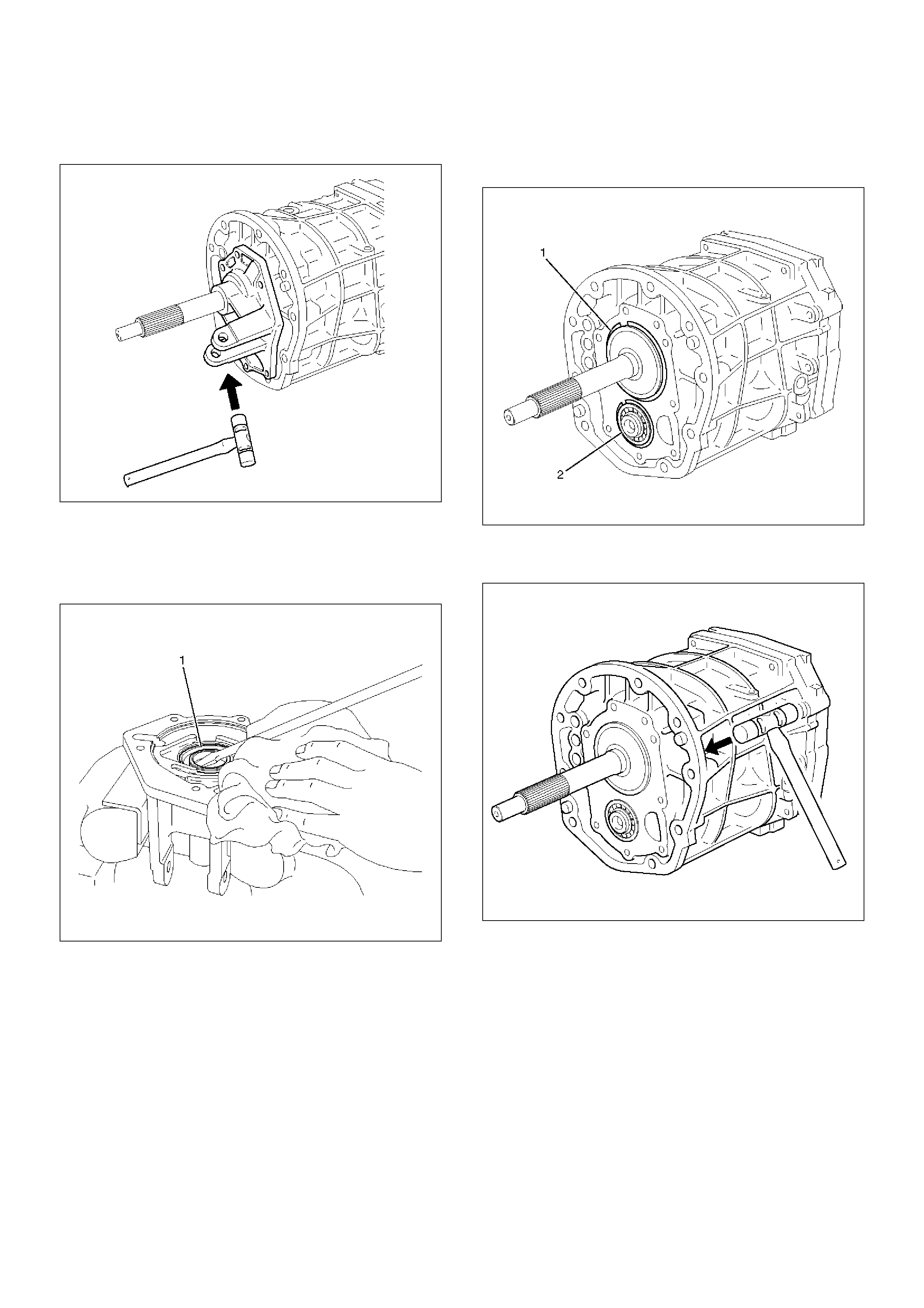
2. Using a plastic hammer, carefully tap the front
cover.
220RW017
9. Remove the front cover oil seal.
1. Mount the front cover through the aluminum
plate in a vise.
2. Using screwdriver, remove oil seal (1).
220RW019
10. Remove the transmission case.
1. Using a snap ring expander, remove the 2 snap
rings (1)(2).
226RW004
2. Using a plastic hammer, carefully tap the
transmission case.
220RW020
11. Mount the intermediate plate.
1. Mount the intermediate plate through the
aluminum plate in a vise.
226RW005
12. Remove the slotted spring pin.
1. Using a pin punch and hammer, drive out the pin
from the arm.
226RW025
13. Remove the shift arm set bolt.
1. Remove the 2 bolts from the shift arm.
226RW023
14. Remove the counter 5th gear.
1. Using 2 screwdrivers and hammer, tap out the
snap ring.
226RW024
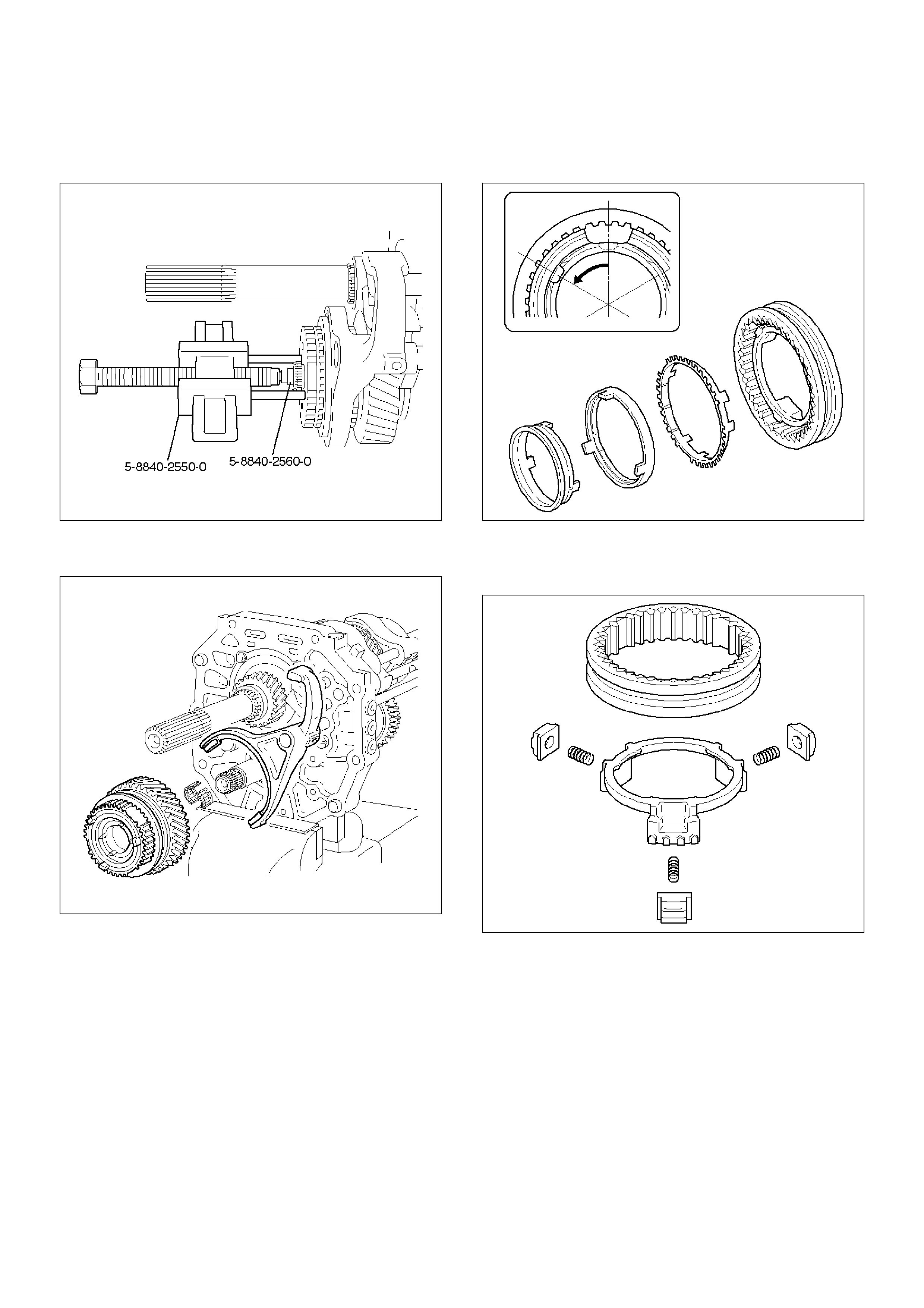
2. Using remover 5–8840–2550–0 (J–42794) and
attachment 5–8840–2560–0 (J–42988), remove
the 5th gear spline piece.
226RW201
3. Remove the hub sleeve No.3, block ring set,
counter 5th gear, bearing and 5th shift arm.
220RW101
4. Remove the synchronizer pull ring, synchronizer
cone ring, and synchronizer outer ring from hub
sleeve No.3.
226RW066
5. Remove the reverse block ring from the hub
sleeve No.3. Remove the 3 inserts and 3
compression springs.
226RW067
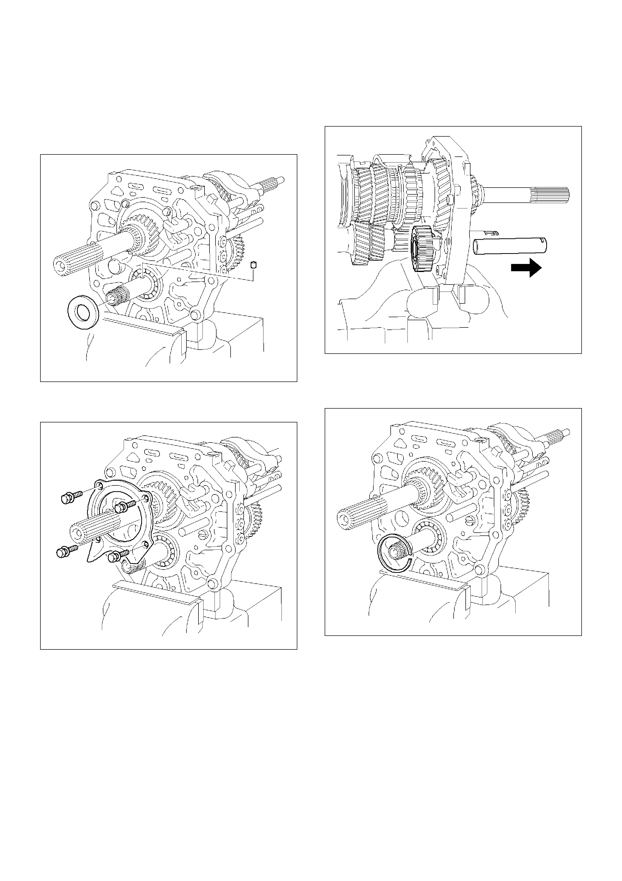
15. Remove the thrust washer.
1. Remove the thrust washer from counter gear
shaft.
2. Remove the thrust washer pin from counter gear
shaft.
226RW018
16. Remove the bearing plate.
1. Remove the 4 bolts and bearing retainer.
226RW016
17. Remove the reverse idle gear.
1. Pull out the shaft foward the rear and remove
the reverse idle gear.
226RW020
18. Remove the counter gear shaft.
1. Using snap ring plier, remove counter gear shaft
center bearing snap ring.
226RW015
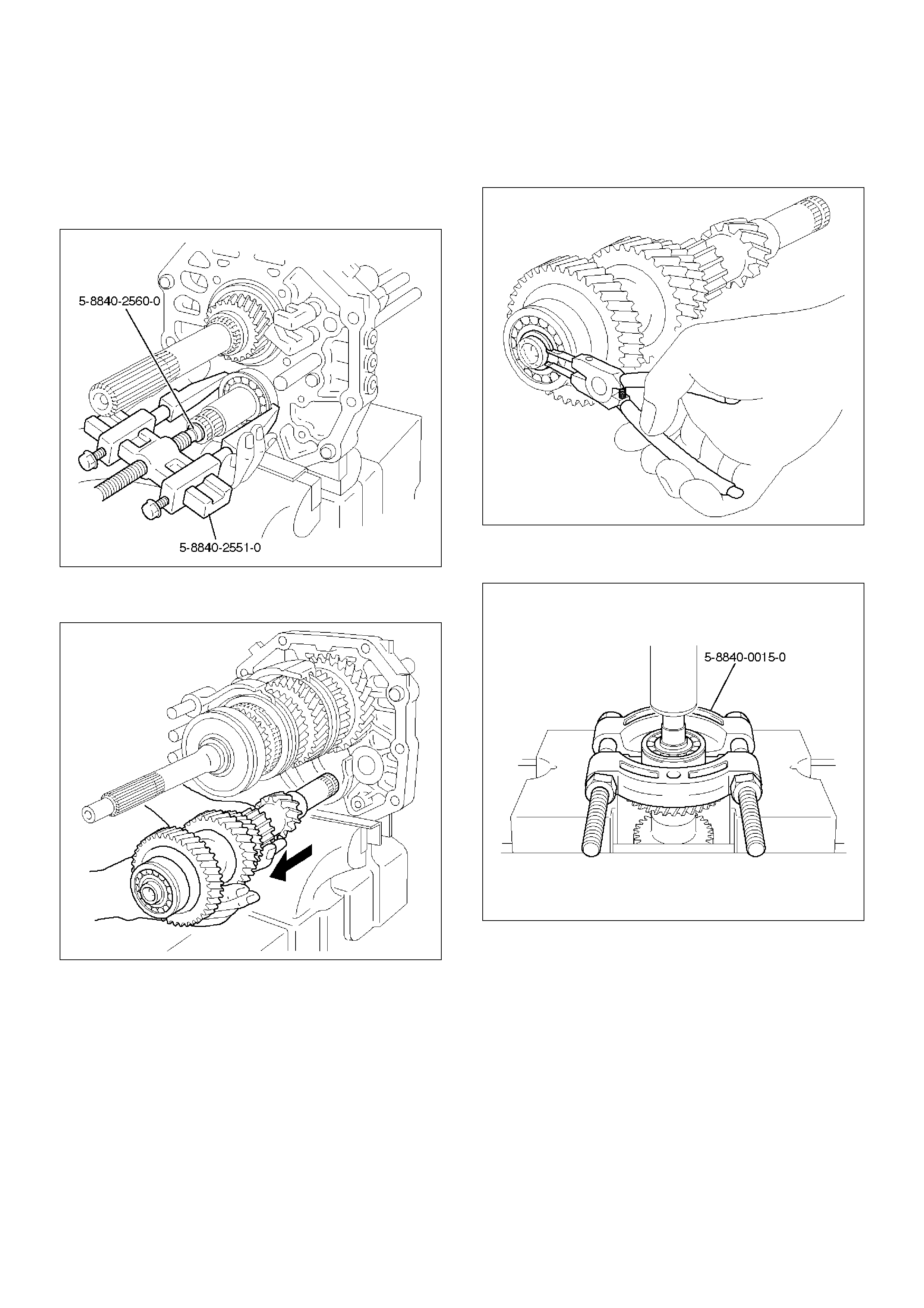
2. Using remover 5–8840–2551–0 (J–42795) and
attachment 5–8840–2560–0 (J–42988), remove
counter gear shaft center bearing.
NOTE: Be careful not to drop the counter gear, when
removing the bearing.
226RW199
3. Remove the counter gear from intermediate
plate.
226RW030
19. Disassemble the counter gear shaft assembly.
1. Using snap ring pliers, remove the counter gear
shaft front bearing snap ring.
226RW065
2. Using bearing separator 5–8840–0015–0 (J–
22912–01) and a press, remove the bearing.
226RW200
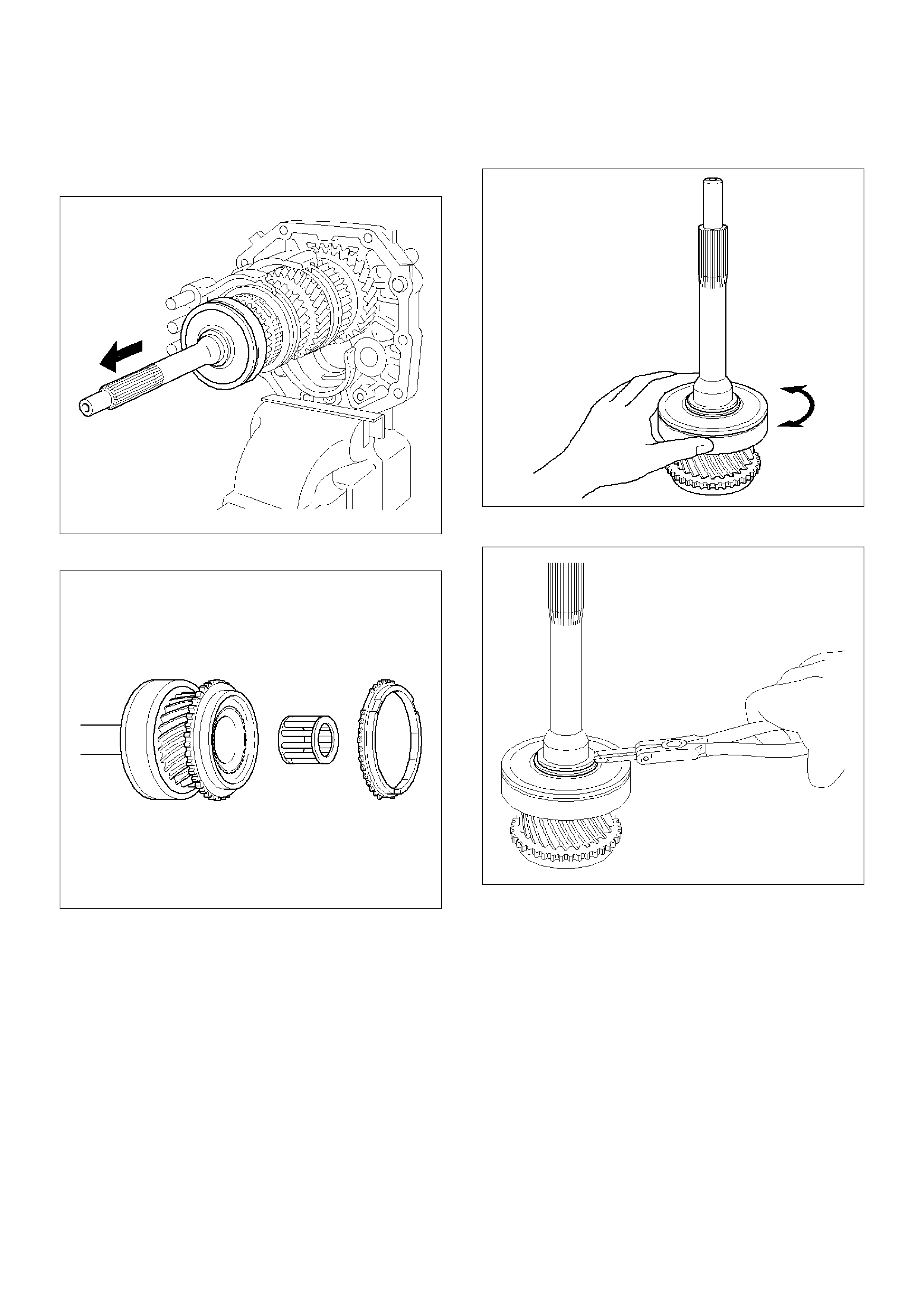
20. Remove the top gear shaft.
1. Remove the top gear shaft from mainshaft.
NOTE: Don't fall needle roller bearing.
226RW029
2. Remove the 4th block ring and roller bearing.
226RW031
21. Disassemble the top gear shaft assembly.
1. Check for wear or damage.
226RW033
2. Remove the front bearing shaft snap ring.
226RW062
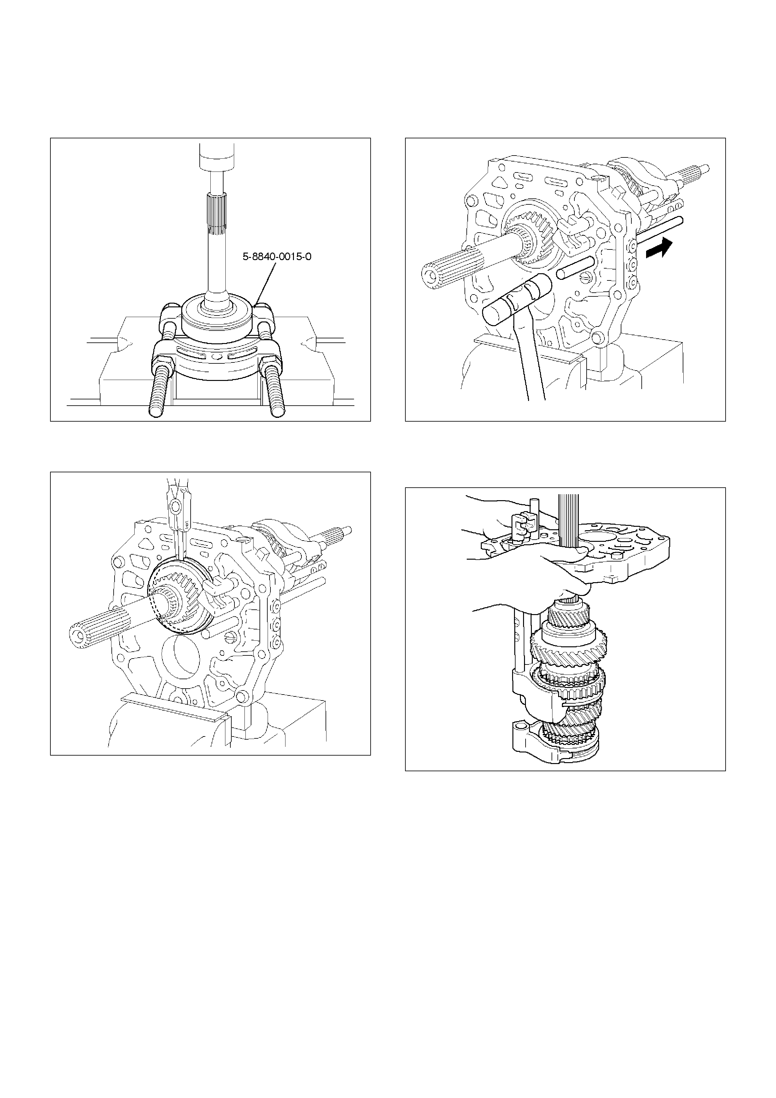
3. Using bearing separator 5–8840–0015–0 (J–
22912–01) and a press, remove the bearing.
226RW202
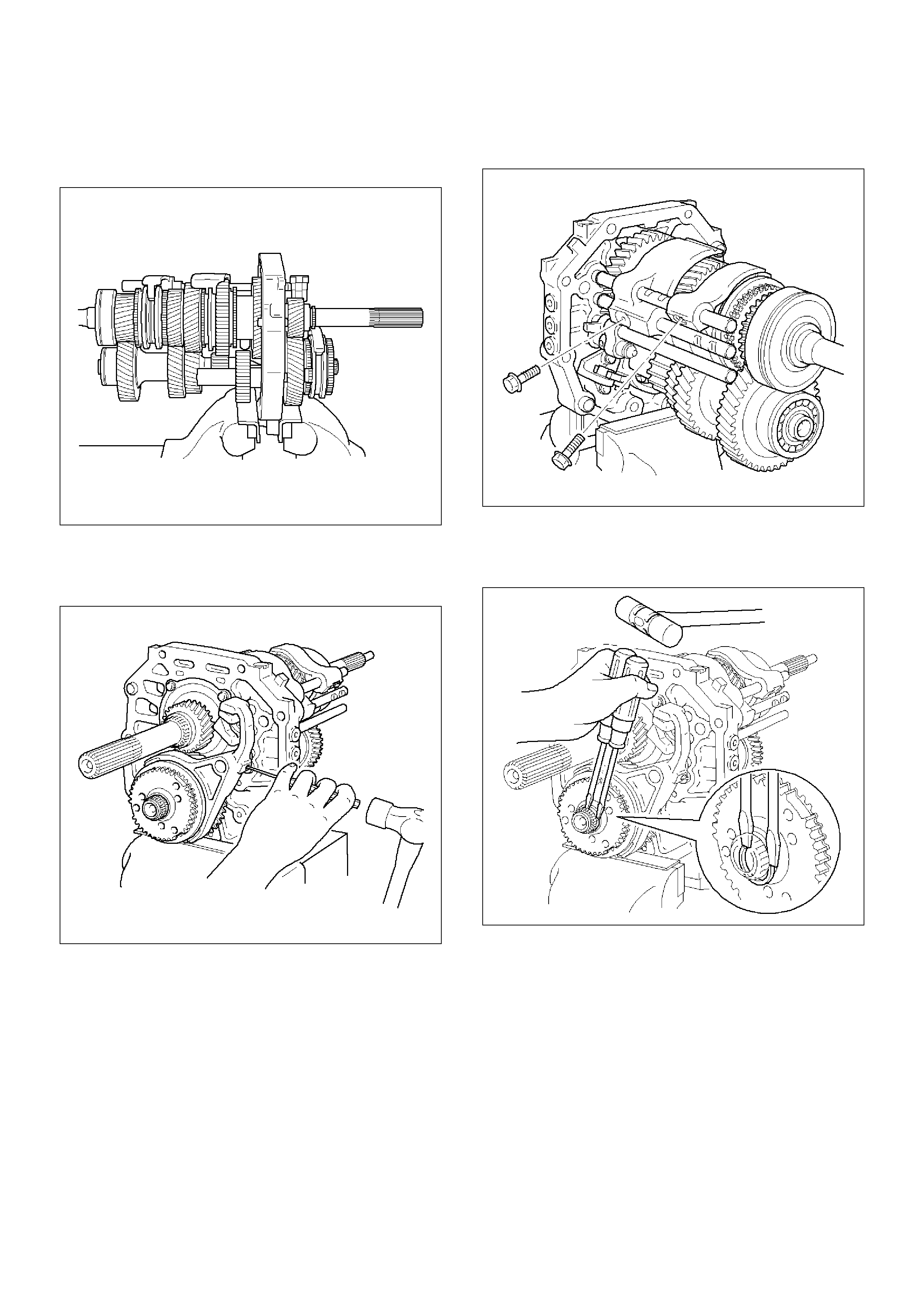
22. Remove the mainshaft.
1. Remove mainshaft bearing snap ring.
226RW035
2. Using a plastic hammer, tap the 5th-reverse shift
rod at the reverse shift side.
226RW034
3. Remove the intermediate plate from a vise.
4. Remove the mainshaft, 1st-2nd shift arm and
3rd-4th shift arm.
226RW014
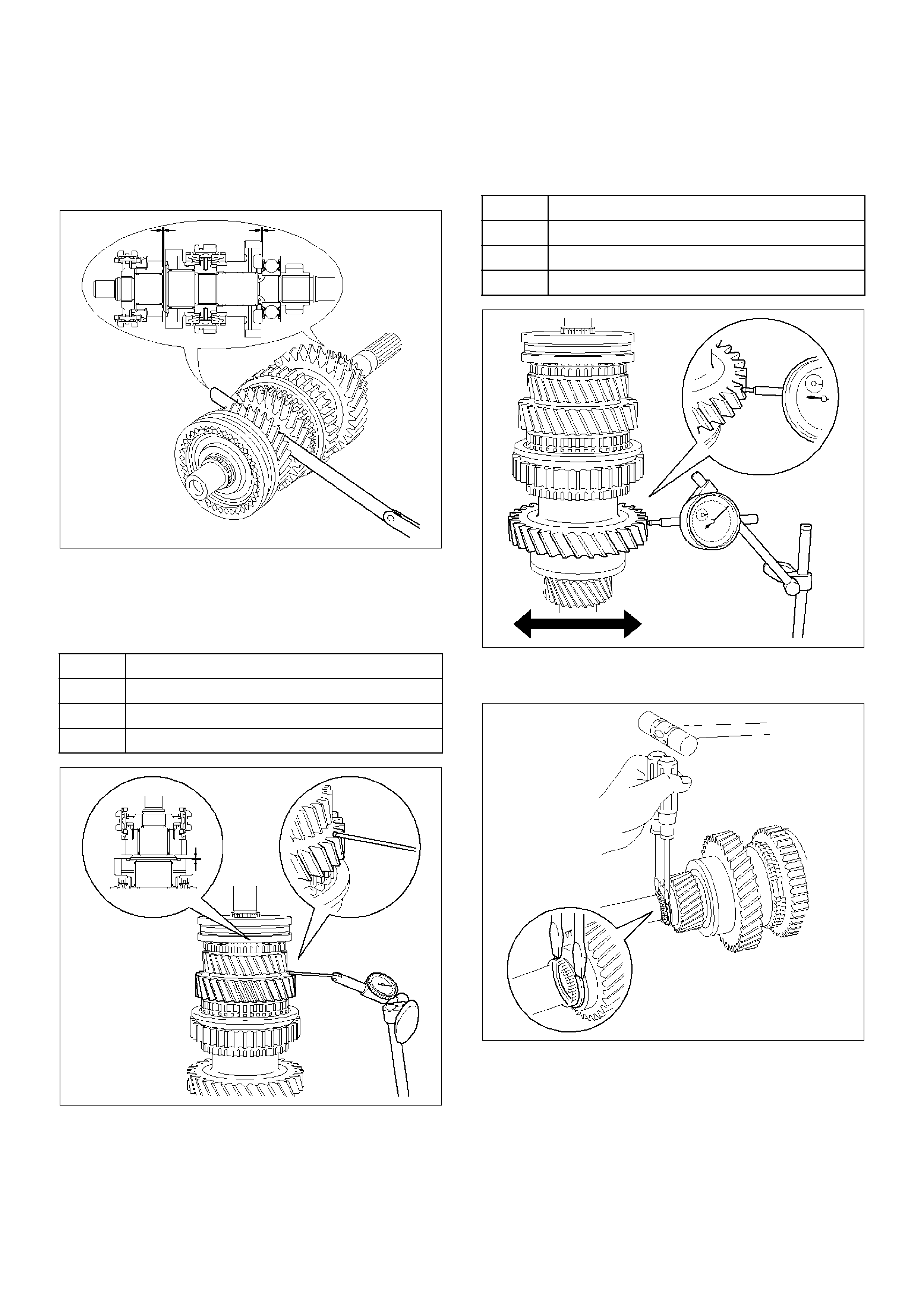
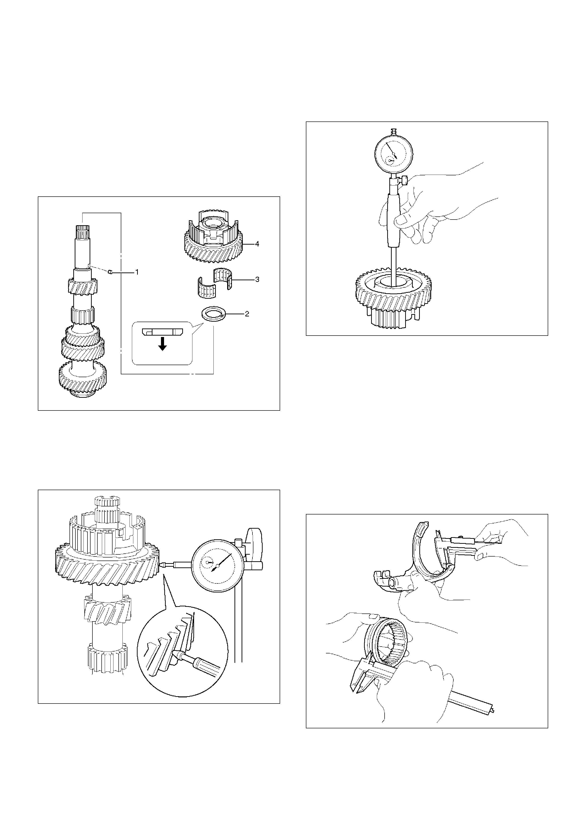
23. Disassemble the mainshaft assembly.
1. Inspect each gear thrust clearance.
1. Using thickness gauge, inspect thrust
clearance (1st gear, 3rd gear).
226RW077
2. Mount the mainshaft through the aluminum
plate in a vise.
3. Using a dial indicator, measure each gear
thrust clearance.
226RW070
2. Inspect each gear radial clearance
1. Using a dial indicator, measure the radial
clearance of each gear.
226RW071
3. Using 2 screwdrivers and hammer, tap out the
snap ring.
226RW053
Gear Standard Clearanse
1st 0.15–0.45mm (0.0059–0.0177 in)
2nd 0.10–0.25mm (0.0039–0.0098 in)
3rd 0.10–0.25mm (0.0039–0.0098in)
Gear Standard Clearanse
1st 0.020–0.074mm (0.00078–0.00291in)
2nd 0.015–0.068mm (0.00059–0.00268in)
3rd 0.015–0.068mm (0.00059– 0.00268 in)
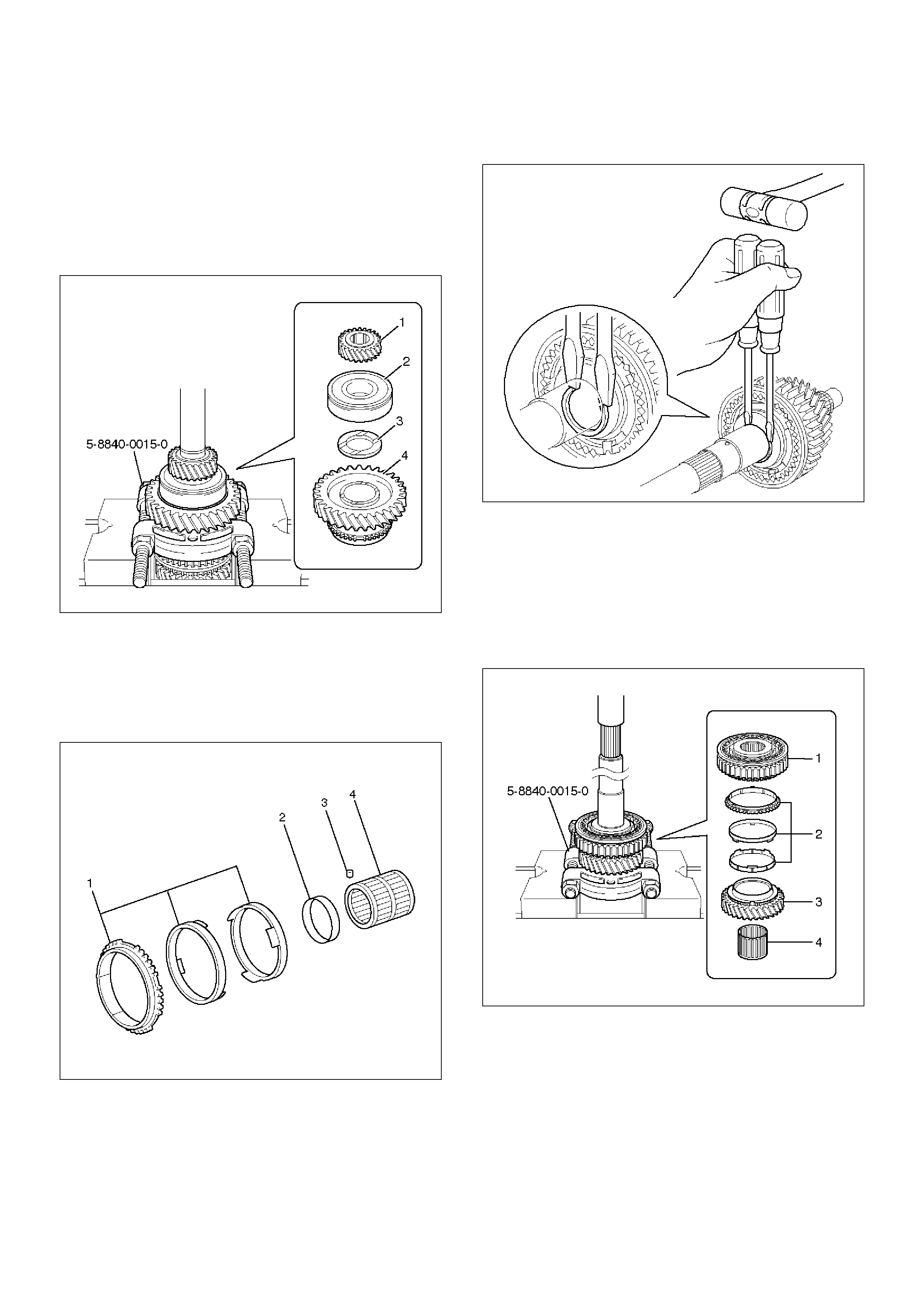
4. Using bearing separator 5–8840–0015–0 (J–
22912–01) and a press, remove the following
parts.
1. 5th gear (1).
2. Mainshaft bearing (2).
3. 1st gear thrust washer (3).
4. 1st gear (4).
226RW197
5. Remove following parts from mainshaft.
1. Synchronizer assembly (1).
2. 1st gear thrust washer pin (3).
3. 1st gear needle roller bearing (4).
4. 1st gear bearing spacer (2).
226RW146
6. Using 2 screwdrivers and hammer, tap out snap
ring.
226RW073
7. Using bearing separator 5–8840–0015–0 (J–
22912–01) and a press, remove the following
parts.
1. Clutch hub No.1 assembly (1).
2. Synchronizer assembly (2).
3. 2nd gear (3).
4. 2nd gear needle roller bearing (4).
226RW198
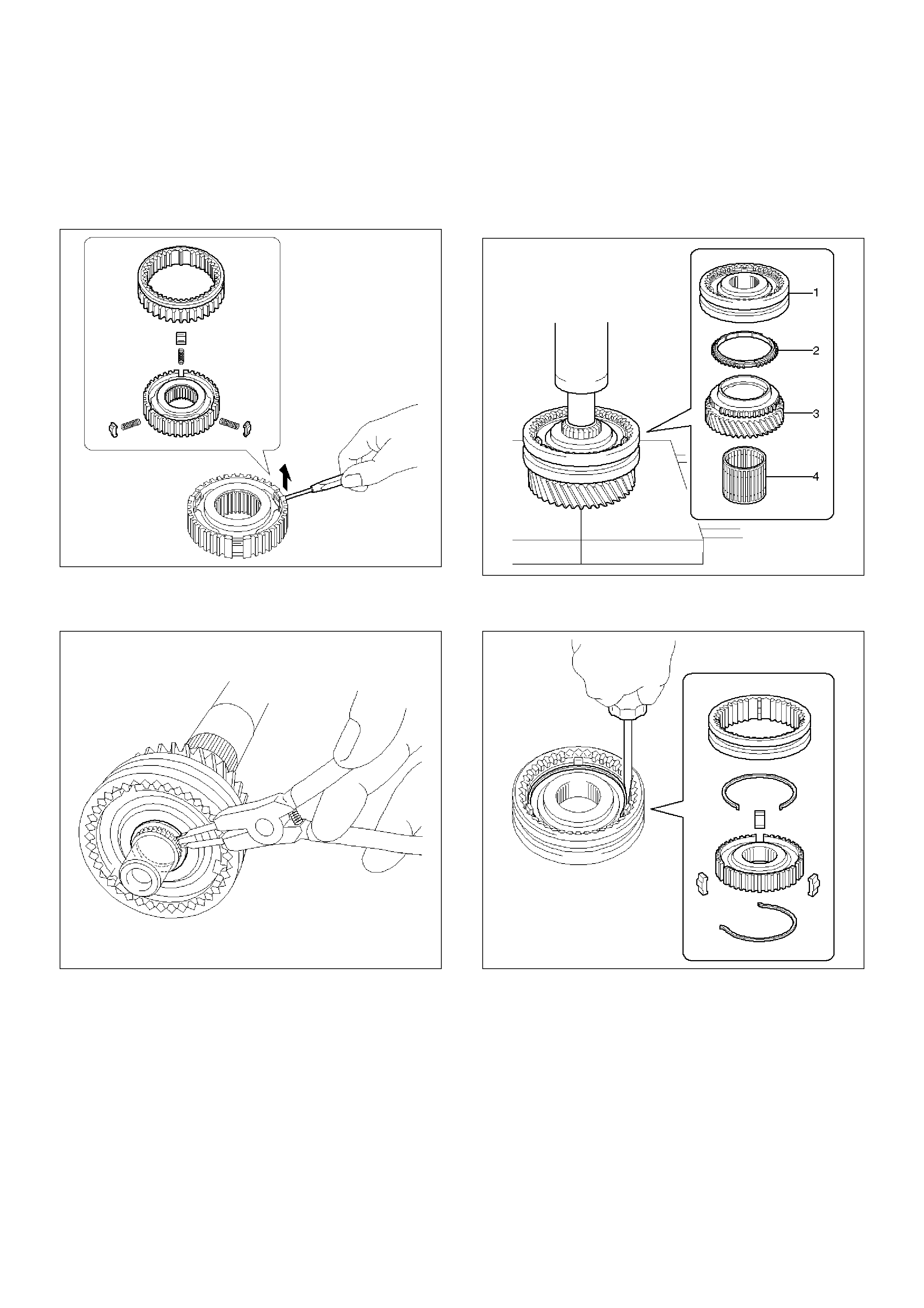
8. Remove the reverse gear from clutch hub No.1.
9. Remove the 3 inserts and 3 compression
springs.
• When removing the inserts, push the insert
spring with a screwdriver.
226RW075
10. Remove the snap ring.
NOTE: Don't damage the bearing surface.
226RW076
11. Using a press, remove following parts.
1. Clutch hub No.2 assembly (1).
2. 3rd block ring (2).
3. 3rd gear (3).
4. 3rd gear needle roller bearing (4).
226RW091
12. Using screwdriver, remove the 2 insert springs,
hub sleeve No.2, clutch hub No.2 and 3 inserts.
226RW090
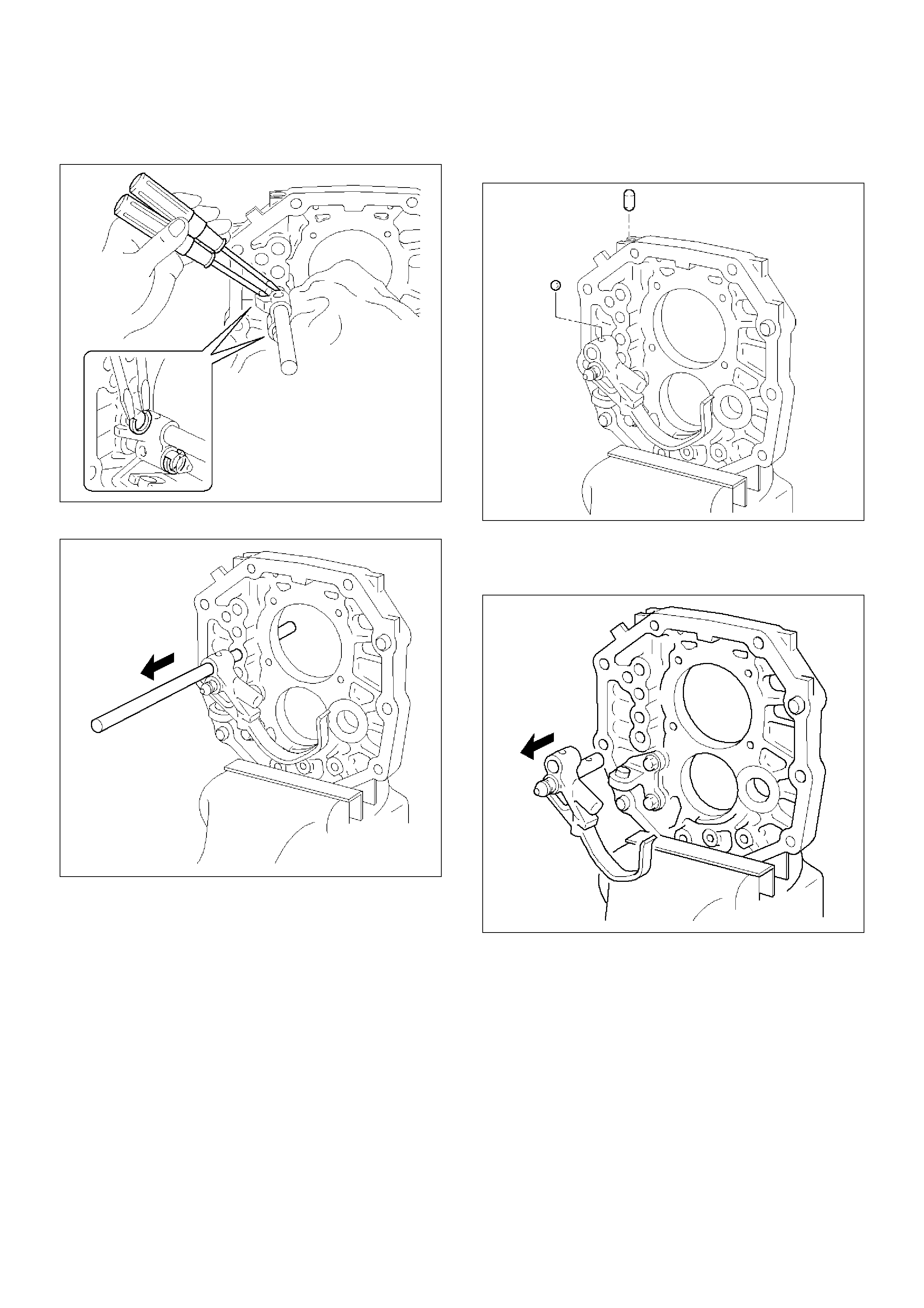
24. Remove the shift parts and interlock parts.
1. Mount the intermediate plate through the
aluminum plate in a vise.
2. Using a plastic hammer, tap the 5th shift rod on
the neutral.
226RW052
3. Using a torx socket wrench(T40), remove the 4
plugs.
226RW050
4. Using a magnetic finger, remove 3 springs and
balls.
226RW049
5. Using 2 screwdrivers and a hammer, remove 2
snap rings from each shift fork rod.
226RW048
6. Pull out the 3rd–4th shift rod at the rear.
226RW047
7. Using a magnetic finger, remove the interlock
pin and straight pin.
226RW043
8. Pull out the 1st–2nd shift rod at the rear.
226RW045
9. Using a magnetic finger, remove the interlock
pin.
226RW042
10. Using 2 screwdrivers and a hammer, remove 2
snap rings.
226RW041
11. Pull out the 5th-reverse shift rod at the front.
226RW040
12. Using a magnetic finger, remove the interlock
pin from the intermediate plate. Remove the
ball from the reverse shift arm No.1.
226RW039
13. Pull out at the rear reverse shift rod, reverse
shift arm No.1 and reverse shift arm No.2 at the
same time.
226RW038
14. Pull out reverse shift rod from reverse shift arm
No.1.
NOTE: Be sure remove at the rear.
226RW055
15. Using a magnetic finger, remove the ball and
spring from reverse shift arm No.1.
226RW056
16. Remove the reverse shift arm No.2 E–ring.
Remove the reverse shift arm No.2 from reverse
shift arm No.1.
226RW089
17. Remove the 2 bolts and reverse shift arm
bracket.
226RW054
Inspection
1. Counter 5th gear radial clearance.
1. Install the following parts to the counter gear
shaft.
1. Counter 5th gear thrust washer pin (1).
2. Counter 5th gear thrust washer (2).
3. Counter 5th gear needle bearing( 3).
4. Counter 5th gear (4).
226RW088
2. Mount the counter gear shaft through the
aluminum plate in vise.
3. Using a dial indicator, measure the counter 5th
gear radial clearance.
Standard: 0.015– 0.068mm (0.00059 –0.00268in)
226RW183
4. Using a inside dial indicator, measure the gear
inside diameter.
Standard: 38.015–38.040mm (1.49665– 1.49763 in)
226RW085
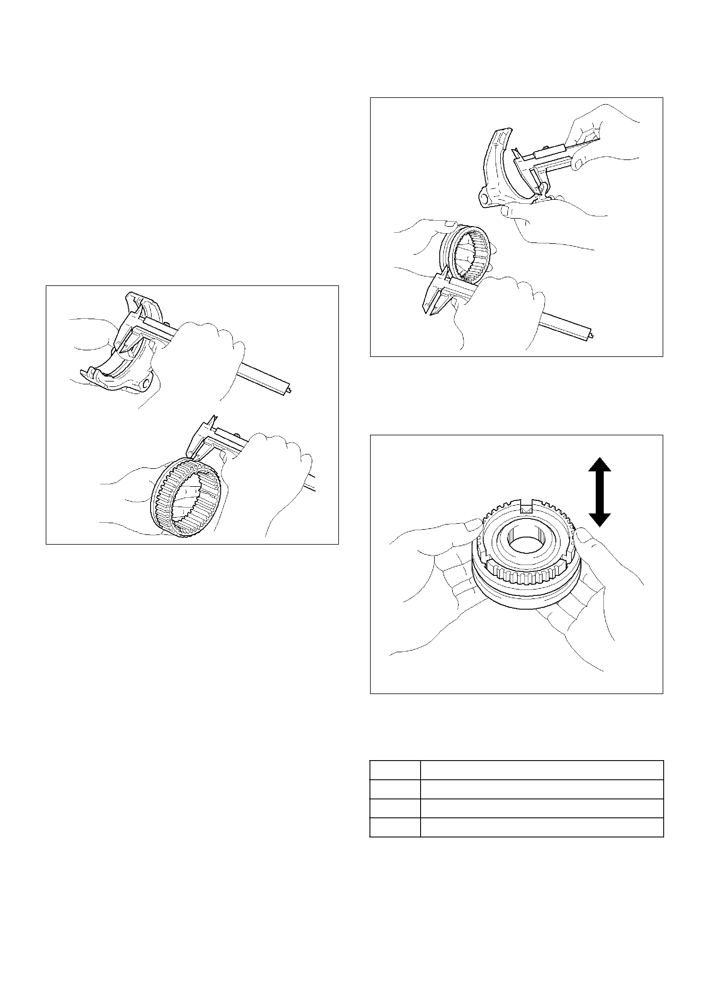
2. 5th-reverse shift arm and hub sleeve No.3
clearance.
1. Using a vernier caliper, measure the 5th-reverse
shift arm thickness.
Reference: 10.2 mm(0.402in)
2. Using a vernier caliper, measure the center
groove of hub sleeve No.3. Calculate the
clearance between the hub sleeve No.3 and
shift arm.
Standard: 0.26–0.84mm (0.0102–0.0331in)
Reference: Center groove dimension 10.5mm
(0.413in)
226RW086
3. Reverse block ring set.
1. Using a thickness gauge, measure the
clearance between the counter 5th gear spline
piece and reverse block ring.
Standard: 0.7–1.7mm (0.028–0.067in)
226RW084
4. Reverse idle gear and reverse idle gear shaft.
1. Mount the reverse idle gear and reverse idle
gear shaft in a vise.
2. Using a dial indicator, measure the reverse idle
gear radial clearance.
Standard: 0.040– 0.082mm (0.0016 –0.0032in)
226RW083
3. If the clearance exceeds the maximum,
measure the gear inside diameter and shaft
diameter.
Standard
Shaft Diameter: 23.979–24.000mm (0.94405–
0.94488in)
Gear Diameter: 24.040–24.061mm (0.94645–
0.94728in)
226RW082
5. Reverse shift arm No.2 thrust clearance.
1. Using a thickness gauge, measure the
clearance between the reverse idle gear and
shift arm No.2.
Standard: 0.05–0.35mm (0.002–0.014in)
226RW081
Reassembly
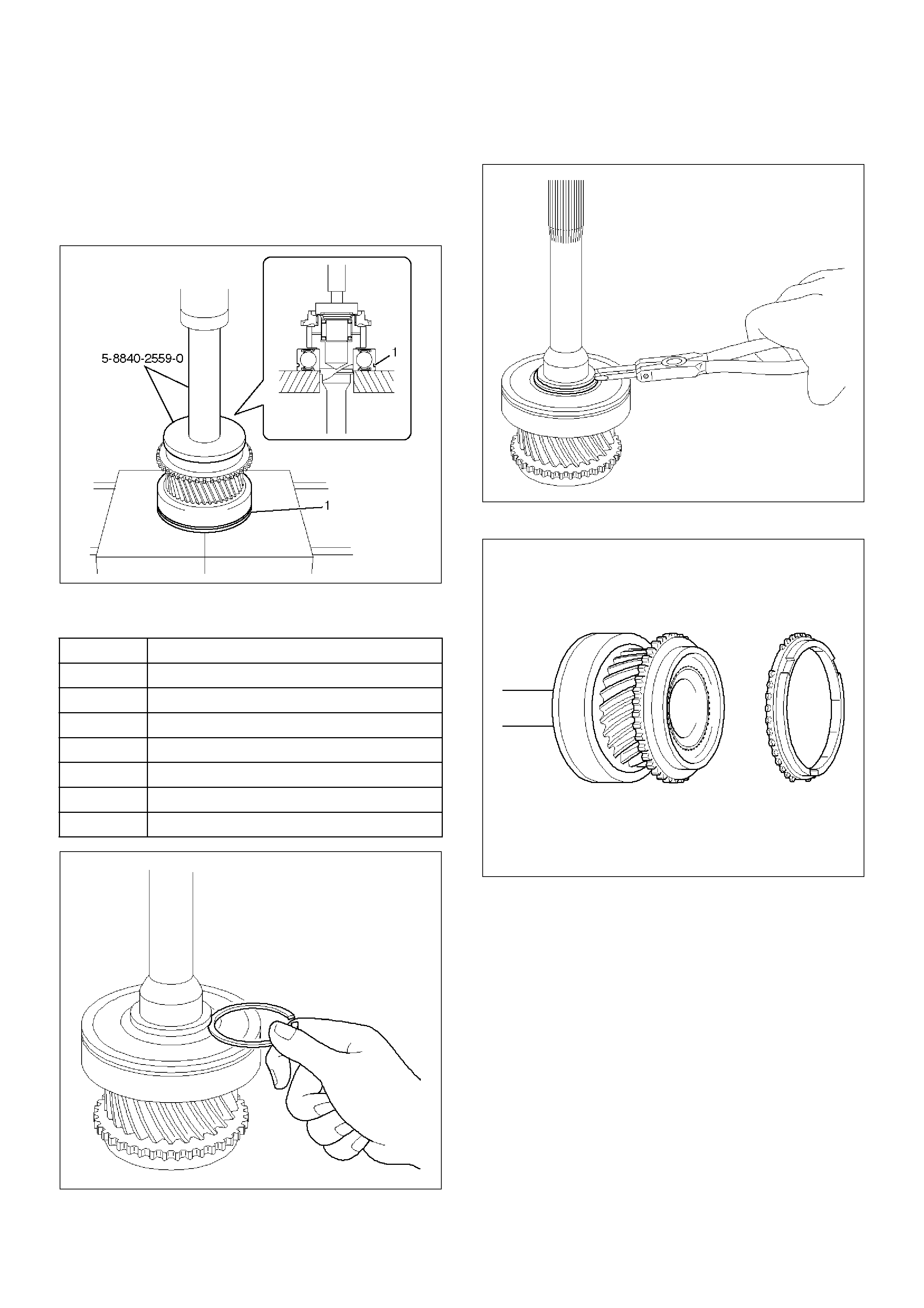
1. Install the top gear shaft assembly.
1. Using installer 5–8840–2559–0 (J–42904) and a
press, install a new bearing.
NOTE: Outer race snap ring groove (1) toward front.
226RW196
2. Select a snap ring that will allow minimum axial
play.
226RW061
3. Using a snap ring expander, install the new snap
ring.
226RW062
4. Install the 4th block ring.
226RW063
Mark Thickness
A 2.10–2.15mm (0.083–0.085in)
B 2.15–2.20mm (0.085–0.087in)
C 2.20–2.25mm (0.087–0.089in)
D 2.25–2.30mm (0.089–0.091in)
E 2.30–2.35mm (0.091–0.093in)
F 2.35–2.40mm (0.093–0.095in)
G 2.40–2.45mm (0.095–0.097in)
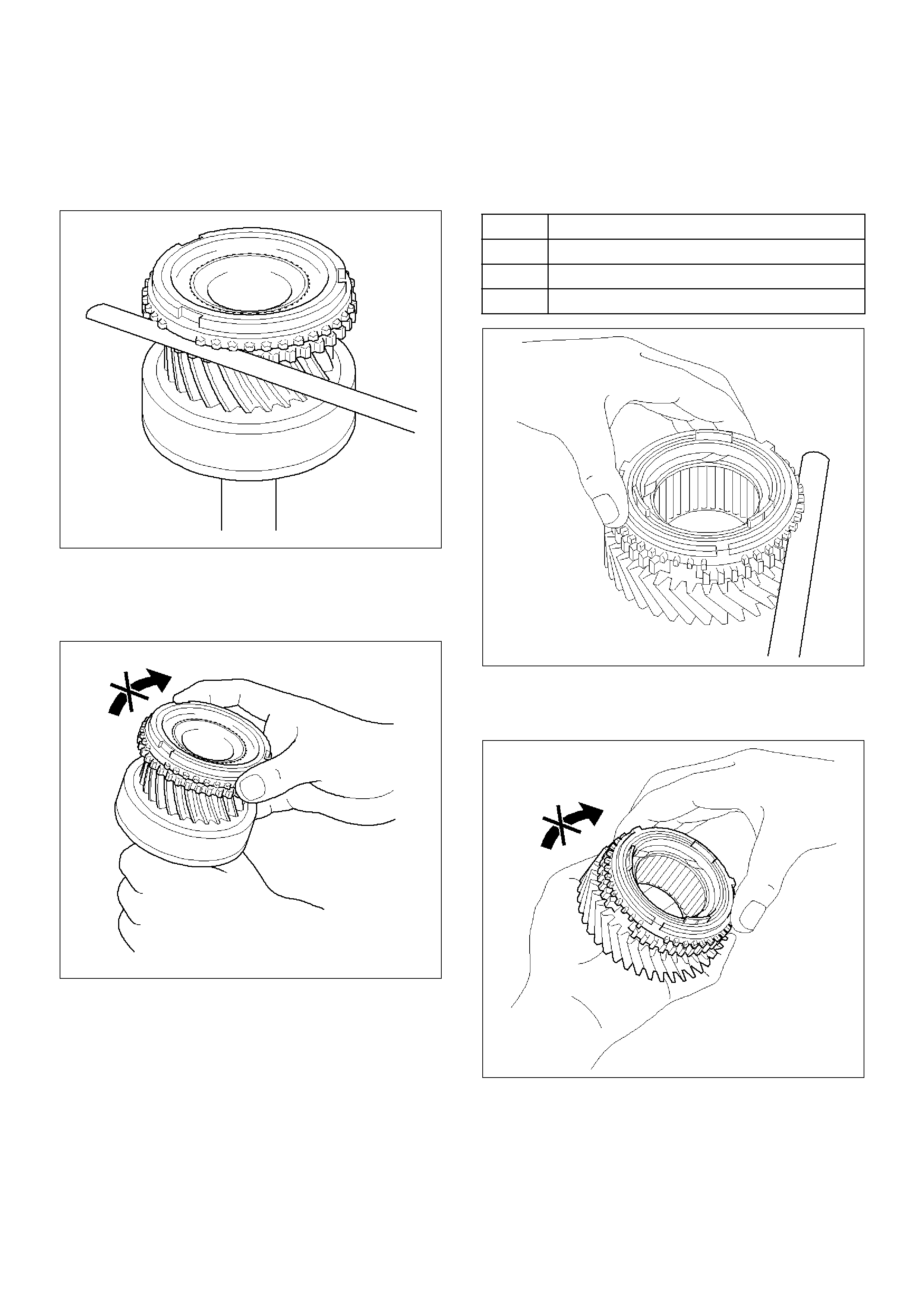
5. Using a thickness gauge, measure the
clearance between the 4th block ring back and
gear spline end.
Standard: 0.75– 1.65mm (0.030–0.065in)
226RW064
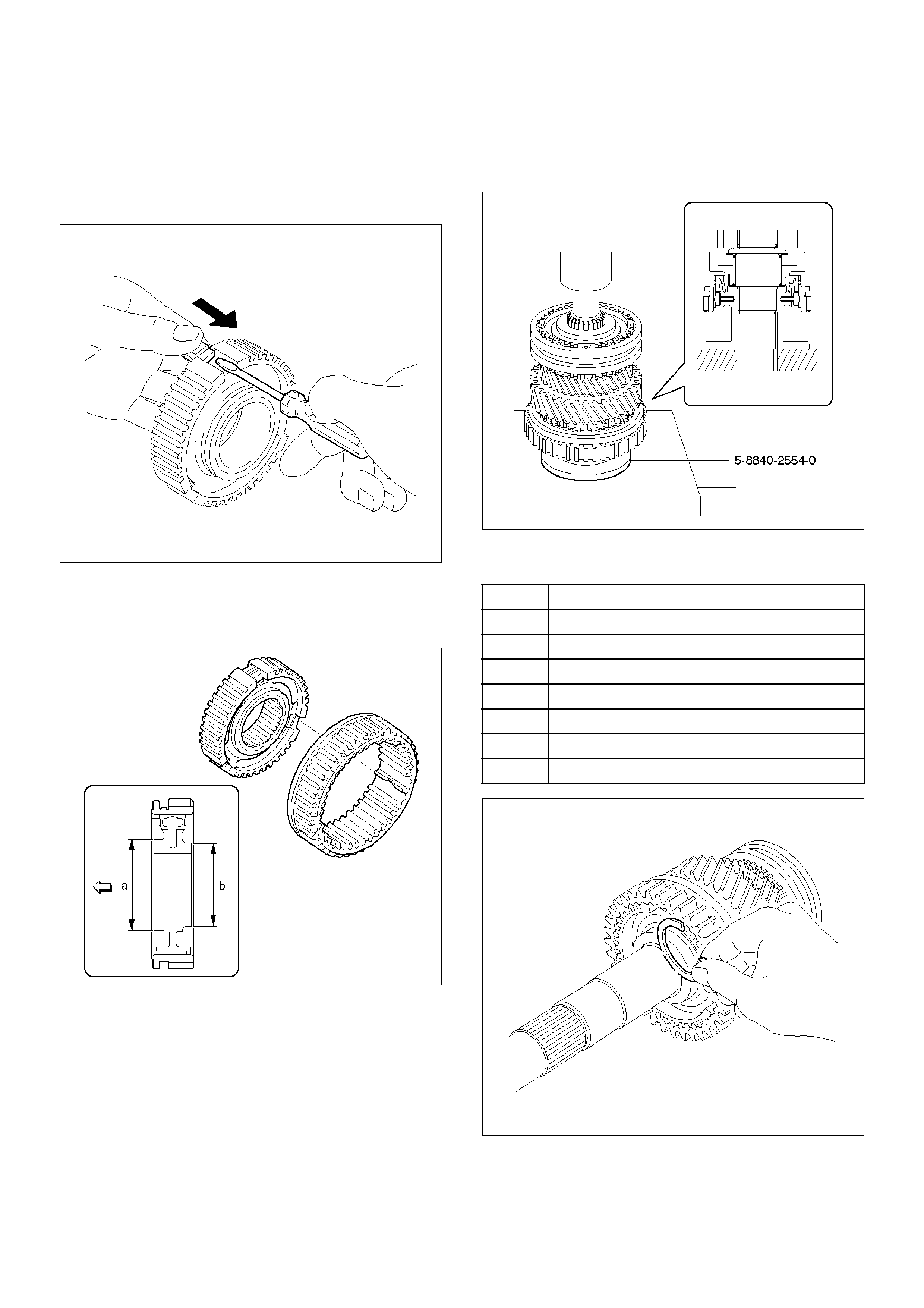
6. Check the braking effect of the block ring. Turn
the block ring in one direction while pushing it to
the gear cone. Check that the ring locks. If it
does not lock, replace the block ring.
226RW060
7. Install the needle roller bearing.
2. Reassemble the mainshaft assembly.
NOTE: Apply all parts with engine oil before installing
them.
3. Inspect block ring
1. Using a thickness gauge, measure the
clearance between the synchronizer ring back
and gear spline end.
226RW105
2. Turn the synchronizer ring in one direction while
pushing it to the gear cone. Check that the ring
locks.
226RW106
Gear Standard Clearanse
1st 0.80–1.60mm (0.032–0.063 in)
2nd 0.65–1.75mm (0.026–0.069 in)
3rd 0.75–1.65mm (0.030–0.065in)
4. Inspect hub sleeve and shift arm.
1st–2nd shift arm
1. Using a vernier caliper, measure center groove
of the 1st–2nd shift arm.
Reference: 5.28 mm (0.208in)
2. Using a vernier caliper, measure flange of the
reverse gear. Calculate the clearance between
the reverse gear and shift arm.
Reference: Reverse gear flange thickness 5.0
mm. (0.197in)
Standard: 0.15– 0.41mm (0.006–0.016in)
226RW093
3rd–4th shift arm
1. Using a vernier caliper, measure tip of the shift
arm thickness.
Reference: 10.0mm (0.39in)
2. Using a vernier caliper, measure center groove
of the hub sleeve No.2. Calculate the
clearance between the hub sleeve No.2 and
shift arm.
Reference: Center groove dimension 10.2mm
(0.402in)
Standard: 0.15– 0.35mm (0.006–0.014in)
226RW095
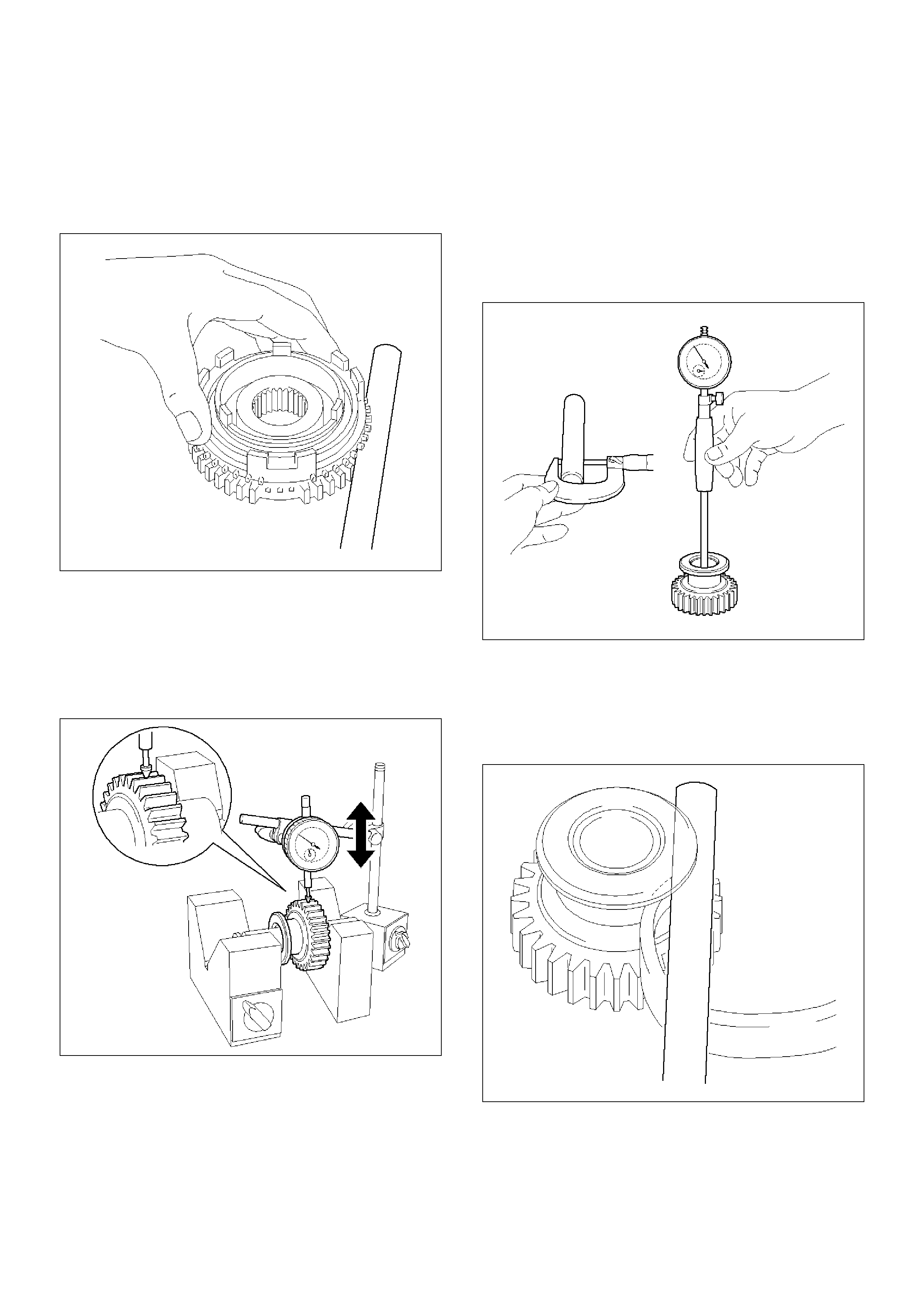
5. Inspect clutch hub and hub sleeve.
1. Check for wear or damage.
2. Install the hub sleeve to the clutch hub, and
check sliding smoothly.
226RW094
6. Inspect gear inside diameter.
1. Using a inside dial indicator, measure the gear
inside diameter.
Gear Standard Diameter
1st 46.015–46.040mm (1.8116–1.8126in)
2nd 53.015–53.040mm (2.0872 –2.0882 in)
3rd 44.015–44.040mm (1.7329–1.7339 in)
226RW096
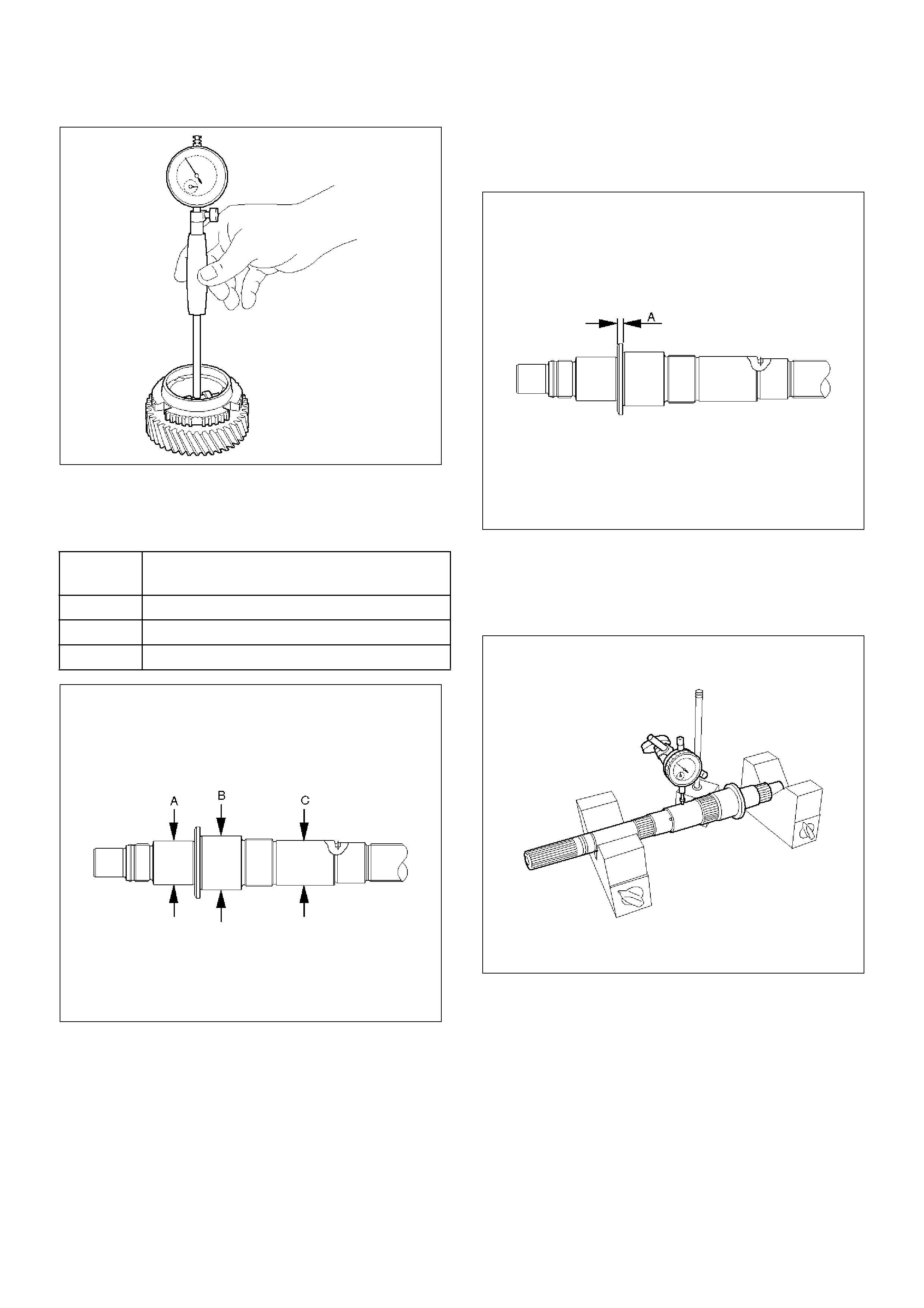
7. Inspect mainshaft.
1. Using a micrometer, measure the outer
diameter of the mainshaft journal.
226RW078
2. Using a micrometer, measure the mainshaft
flange thickness.
Standard: 5.0mm (0.197in)
226RW079
3. Install the mainshaft to V-blocks.
4. Use a dial indicator to measure the mainshaft
central portion run-out.
Standard: less than 0.015mm (0.0006in)
226RW097
Measure
Position Standard
A 37.984–38.000mm (1.4954–1.4961 in)
B 46.984–47.000mm (1.8498–1.8504 in)
C 38.979–38.995mm (1.5346–1.5352 in)
8. Install 3rd gear.
1. Install the 3rd gear needle bearing, 3rd gear and
3rd block ring to the mainshaft.
226RW098
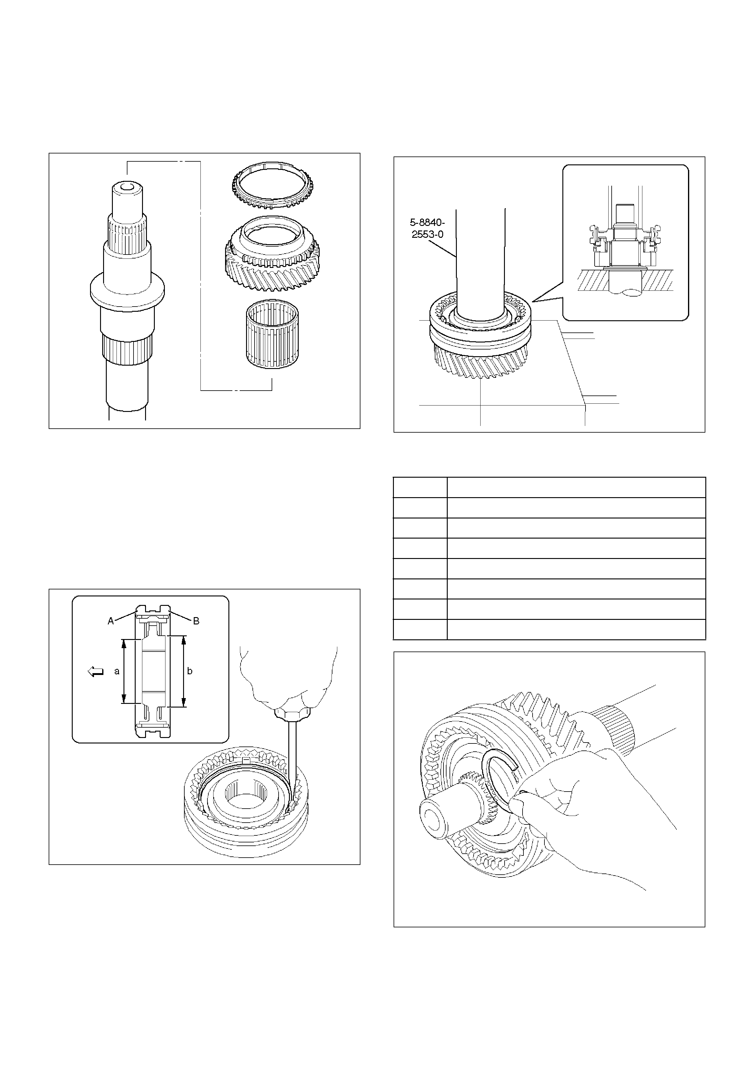
9. Install the clutch hub No.2.
1. Install the clutch hub No.2 and hub sleeve No.2.
NOTE: Be careful the direction of the clutch hub No.2,
as shown.
2. Using a screwdriver, install 3 inserts and 2
springs.
NOTE: Position the insert springs so that their end
gaps are not in line.
226RW099
3. Using installer 5–8840–2553–0 (J–42797) and a
press, install the clutch nob No.2 and hub
sleeve No.2 to the mainshaft.
NOTE:
• Align the brock ring slots with the inserts.
• Check that the gear rotates smoothly.
226RW206
4. Select a snap ring that will allow minimum axial
play.
226RW102
Mark Thickness
A 1.80–1.85mm (0.071–0.073in)
B 1.85–1.90mm (0.073–0.075in)
C 1.90–1.95mm (0.075–0.077in)
D 1.95–2.00mm (0.077–0.079in)
E 2.00–2.05mm (0.079–0.081in)
F 2.05–2.10mm (0.081–0.083 in)
G 2.10–2.15mm (0.083–0.085in)
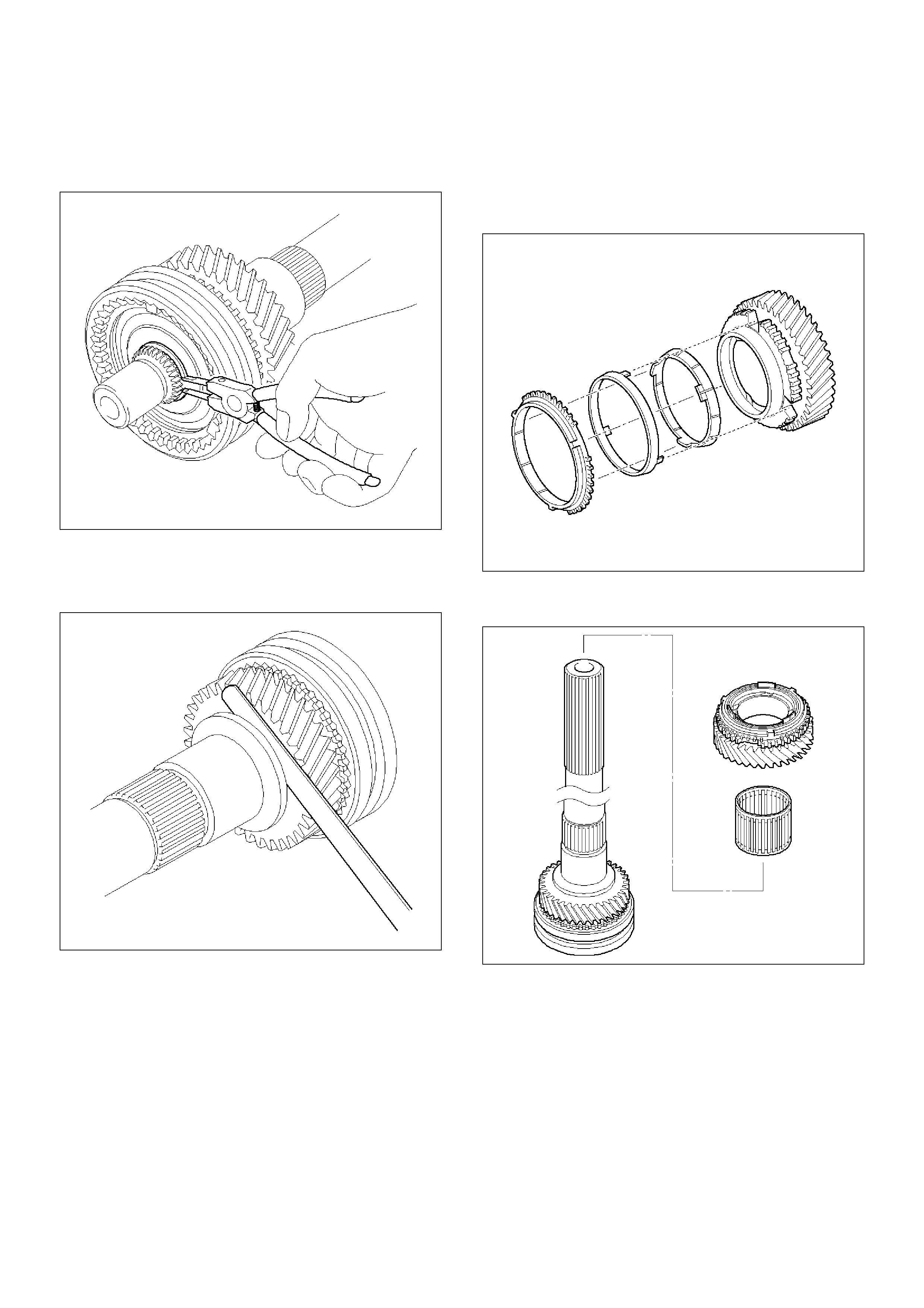
5. Using a snap ring expander, install the new snap
ring.
NOTE: Be careful not to damage the bearing surface.
226RW101
6. Using a thickness gauge, inspect the 3rd gear
thrust clearance.
Standard: 0.10– 0.25mm (0.004–0.010in)
226RW103
10. Install the 2nd gear.
1. Install the synchronizer ring set No.1 to the 2nd
gear.
NOTE: Align the nail of middle ring with gear spline
slots.
226RW104
2. Install the needle roller bearing, 2nd gear and
2nd gear block ring set to the mainshaft.
226RW107
11. Install the clutch hub No.1.
1. Install the 3 inserts and 3 insert springs to the
clutch hub No.1.
Reference: While pushing the insert spring
with a screwdriver, install the inserts.
226RW108
2. Install the clutch hub No.1 to the reverse gear.
NOTE: Check the clutch hub No.1 installing direction,
as shown.
226RW109
3. Using installer 5–8840–2554–0 (J–42798) and a
press, install the hub No.1 by retaining the
reverse gear.
NOTE:
• Align the projection of inner ring with hub No.1 slots.
• Check that the gear rotates smoothly.
226RW205
4. Select a snap ring that will allow minimum axial
play.
226RW111
Mark Thickness
A 2.30–2.35mm (0.091–0.093in)
B 2.35–2.40mm (0.093–0.095in)
C 2.40–2.45mm (0.095–0.097in)
D 2.45–2.50mm (0.097–0.098in)
E 2.50–2.55mm (0.098–0.100in)
F 2.55–2.60mm (0.100–0.102 in)
G 2.60–2.65mm (0.102–0.104in)
5. Using a screwdriver and hammer, install the
snap ring.
NOTE: Be careful not to damage the bearing surface.
6. Check that the gear rotates smoothly.
226RW112
7. Using a dial indicator, measure the 2nd gear
thrust clearance.
Standard: 0.10– 0.25mm (0.004–0.010in)
226RW113
12. Install the 1st gear.
1. Install the following parts:
1. 1st gear bearing spacer (4).
2. 1st gear needle roller bearing (3).
3. Synchronizer assembly (2).
4. 1st gear (1).
NOTE:
• Align the projection of inner ring with hub No.1 slots.
• Check that the gear rotates smoothly.
226RW114
2. Install the 1st gear thrust washer pin and 1st
gear thrust washer to the mainshaft.
NOTE: Align the straight pin with the thrust washer slot.
226RW115
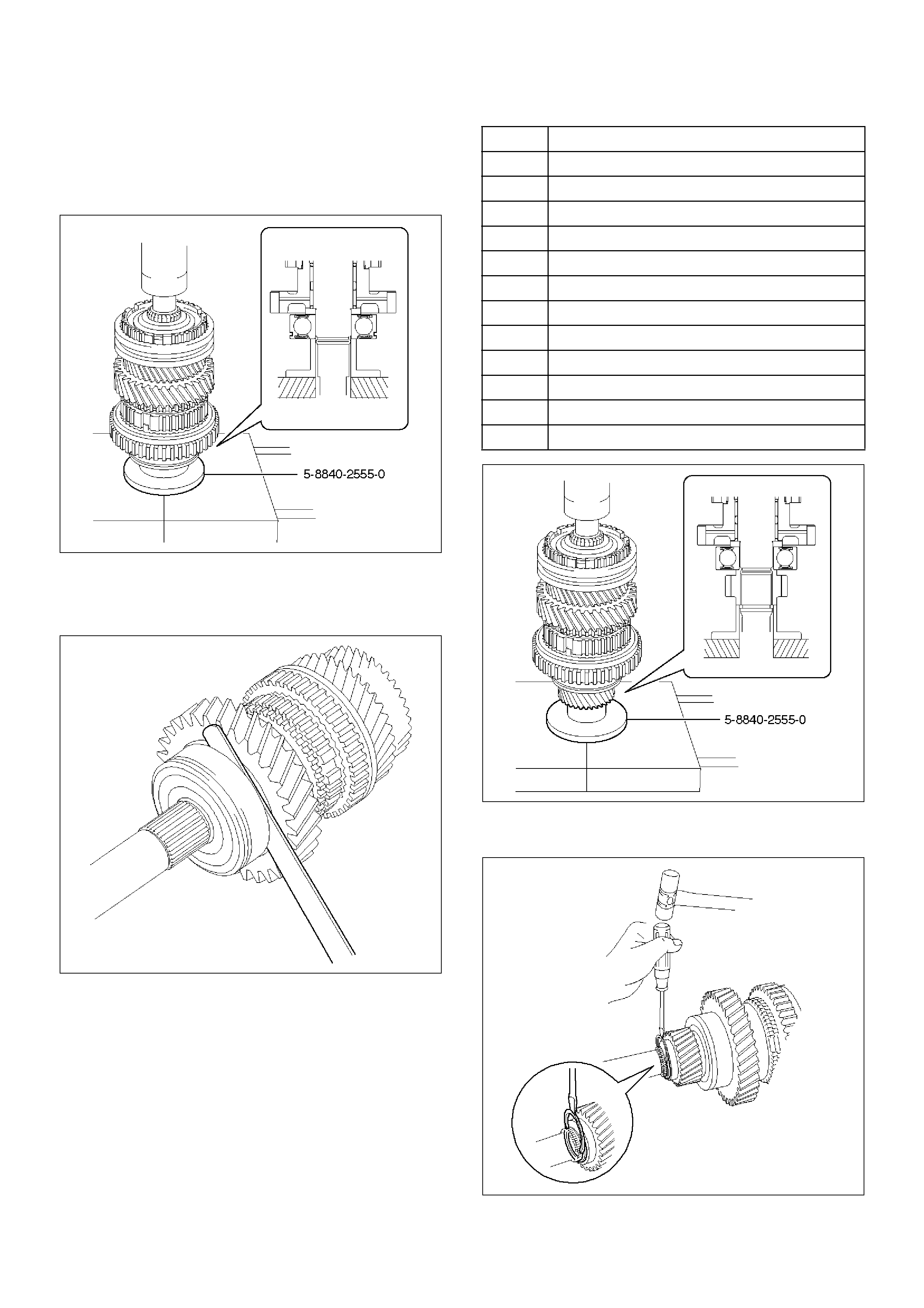
13. Install the mainshaft center bearing.
1. Using installer 5–8840–2555–0 (J–42799) and a
press, install the mainshaft center bearing.
NOTE: Center bearing snap ring groove toward rear.
226RW195
2. Using a thickness gauge, measure 1st gear
thrust clearance.
Standard: 0.10– 0.45mm (0.004–0.018in)
226RW118
14. Install the 5th gear.
1. Using installer 5–8840–2555–0 (J–42799) and a
press, install the 5th gear.
2. Select a snap ring that will allow minimum axial
play.
226RW203
3. Using a screwdriver and hammer, install the
new snap ring.
226RW127
Mark Thickness
C 2.75–2.80mm (0.108–0.110in)
D 2.80–2.85mm (0.110–0.112in)
E 2.85–2.90mm (0.112–0.114in)
F 2.90–2.95mm (0.114– 0.116in)
G 2.95–3.00mm (0.116–0.118in)
H 3.00–3.05mm (0.118–0.120in)
J 3.05–3.10mm (0.120–0.122in)
K 3.10–3.15mm (0.122–0.124in)
L 3.15–3.20mm (0.124–0.126in)
M 3.20–3.25mm (0.126–0.128in)
N 3.25–3.30mm (0.128–0.130in)
P 3.30–3.35mm (0.130–0.132in)
15. Inspect each gear radial clearance.
1. Mount the mainshaft through the aluminum
plate in a vise.
2. Using a dial indicator, measure the radial
clearance of each gear.
226RW071
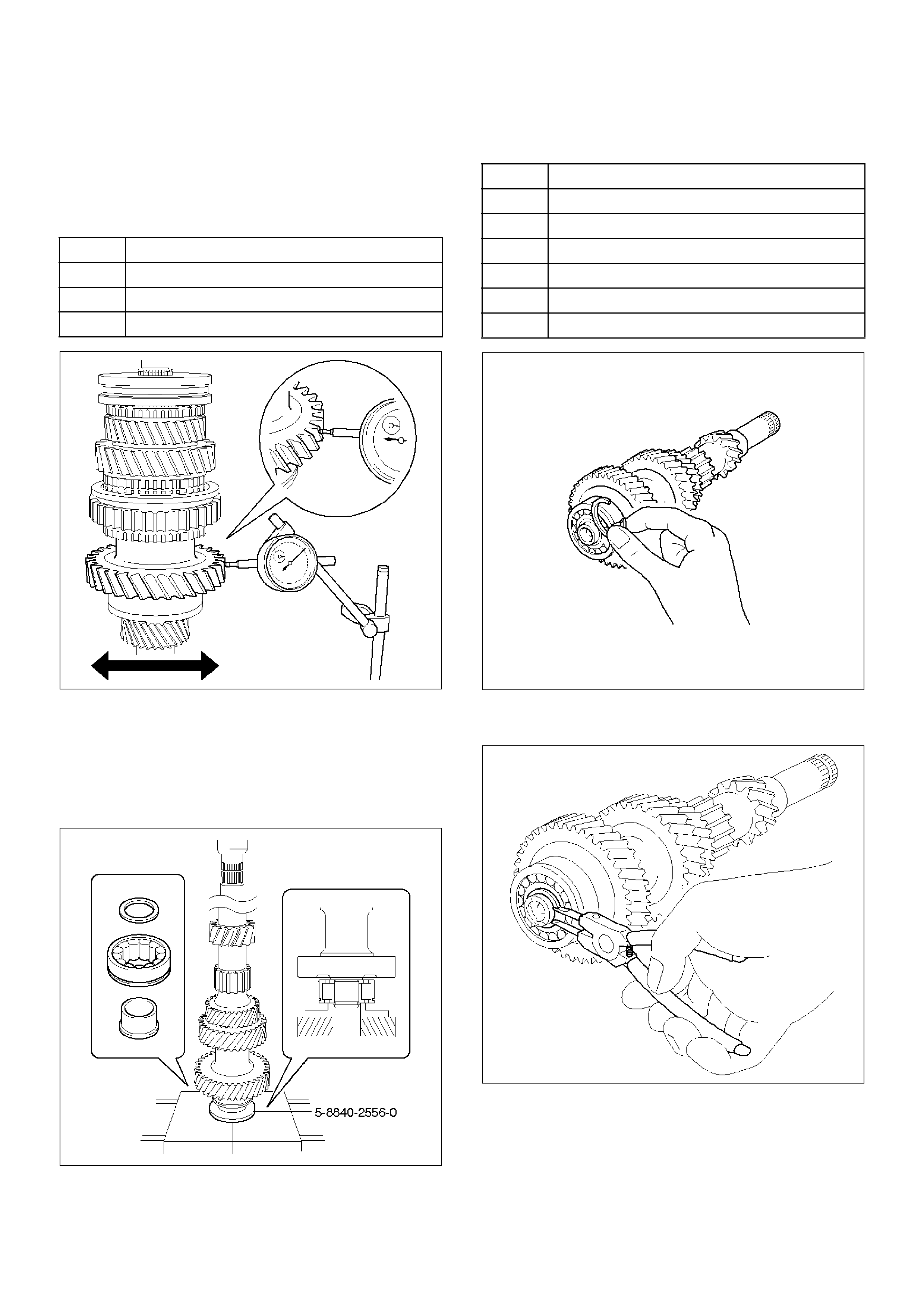
16. Install the counter gear shaft.
1. Check the new counter front bearing inner race
and the side race, as shown.
2. Using installer 5–8840–2556–0 (J–42800) and a
press, install the counter gear shaft front
bearing.
226RW194
3. Select a snap ring that will allow minimum axial
play.
226RW128
4. Using a snap ring expander, install the new snap
ring.
226RW129
Gear Standard Clearanse
1st 0.020–0.073mm (0.0008–0.0029in)
2nd 0.015–0.068mm (0.0006–0.0027 in)
3rd 0.015–0.068mm (0.0006 –0.0027 in)
Mark Thickness
A 2.00–2.05mm (0.079–0.081in)
B 2.05–2.10mm (0.081–0.083in)
C 2.10–2.15mm (0.083–0.085in)
D 2.15–2.20mm (0.085–0.087in)
E 2.20–2.25mm (0.087–0.089in)
F 2.25–2.30mm (0.089–0.091 in)
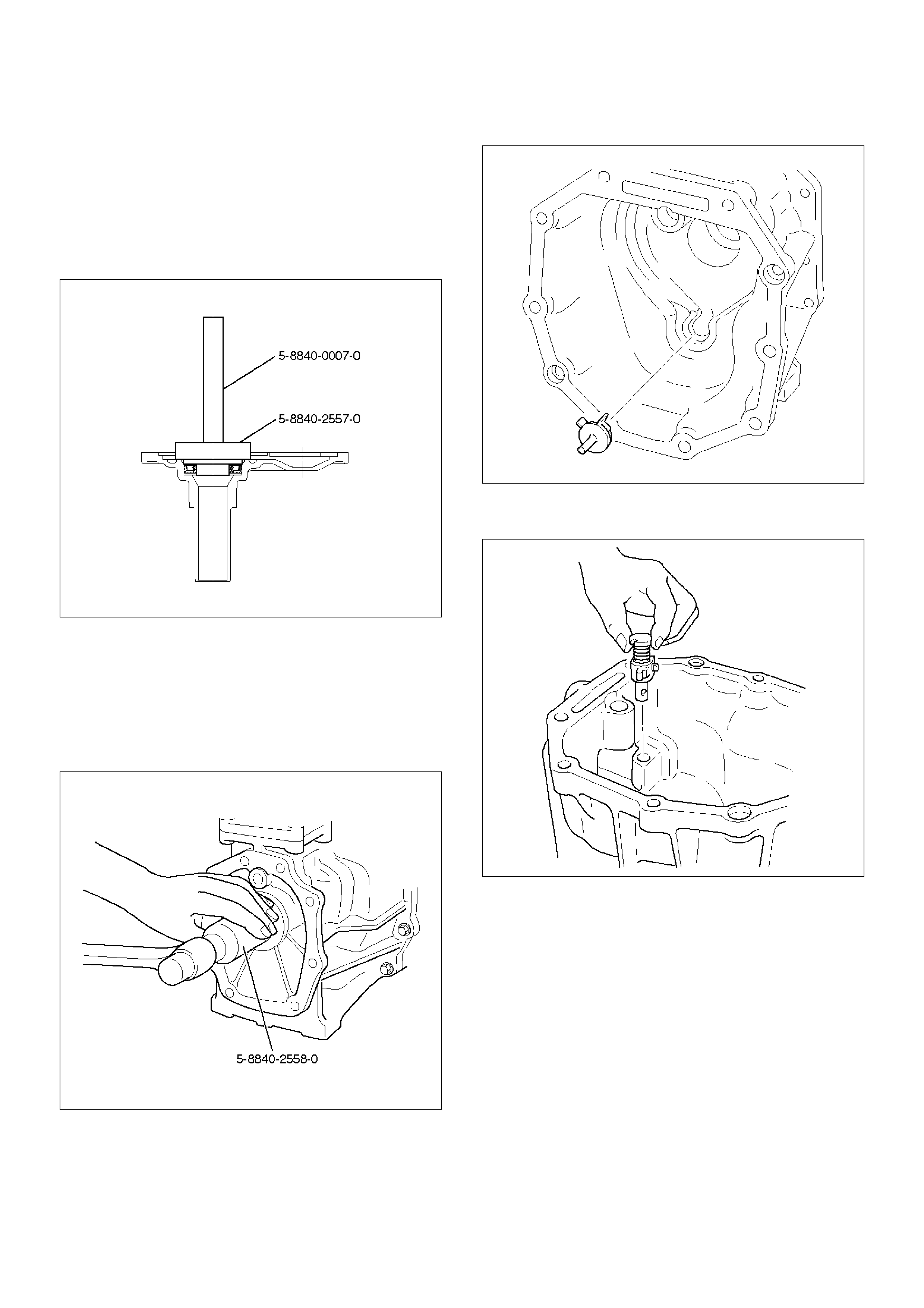
17. Install the front cover.
1. Using installer 5–8840–2557–0 (J–42801), grip
5–8840–0007–0 (J–8092) and a hammer, drive
in a new oil seal.
Drive in depth (from cover end): 11.7±0.5mm
(0.46±0.02in)
2. Apply grease to the seal lip.
220RW113
18. Install the transfer adapter.
1. Using installer 5–8840–2558–0 (J –42802), and
a hammer drive in a new oil seal.
Drive in depth (from transfer adapter):
10.95±0.5mm (0.431 ±0.02in)
2. Apply grease to the oil seal lip.
220RW114
3. Install the oil receiver pipe.
220RW011
4. Install the reverse restrict to the transfer
adapter.
226RW059
5. Using a pin punch and hammer, drive in the
slotted spring pin.
226RW058
6. Clean up the plug and plug hole.
7. Apply sealant to the plug threads. (THREE
BOND 1344 or equivalent)
8. Using a torx socket wrench(T40), install and
torque the plug.
Torque: 19N·m (1.9kg·m/14lbft)
220RW013
9. Using hexagon wrench, install and torque the
plug.
Torque: 37N·m (3.8kg·m/27lbft)
220RW014
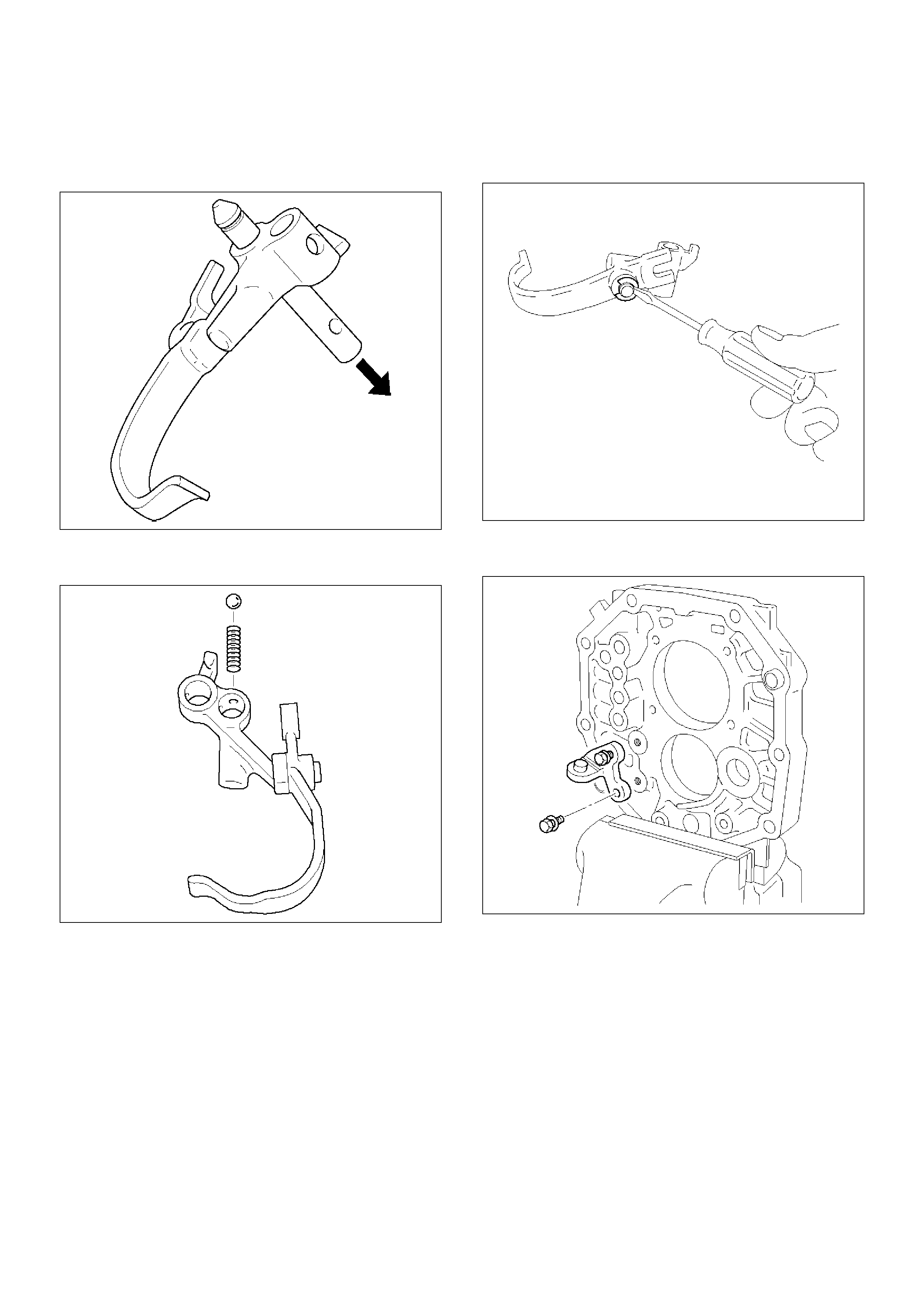
19. Install the reverse shift arm No.1 and reverse shift
arm No.2.
1. Mount the intermediate plate through the
aluminum plate in a vise.
226RW057
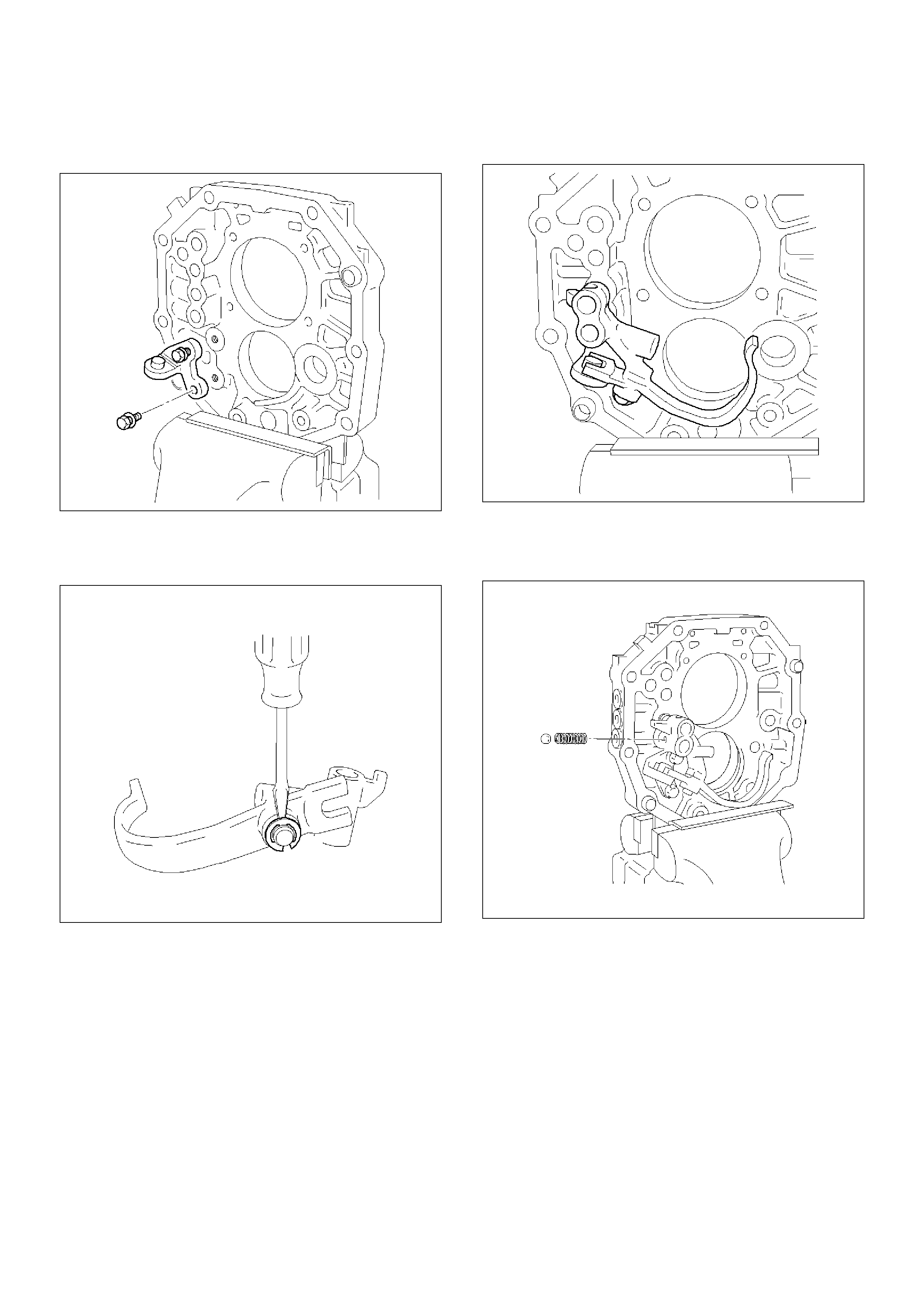
2. Using 2 bolts, install reverse shift arm bracket.
Torque: 18N·m (1.8kg·m/13lbft)
226RW054
3. Install reverse shift arm No.2 to the reverse shift
arm No.1. Using screwdriver and a hammer,
install the new E-ring.
226RW138
4. Install reverse shift arm No.2 to the reverse shift
arm bracket.
226RW012
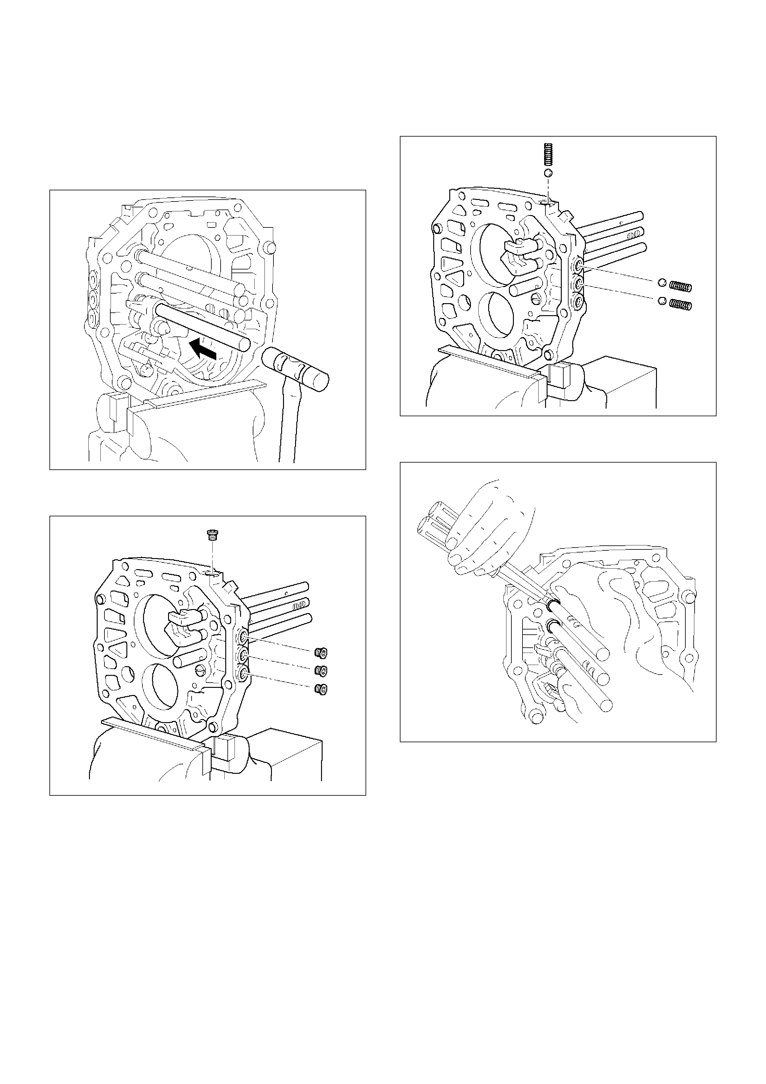
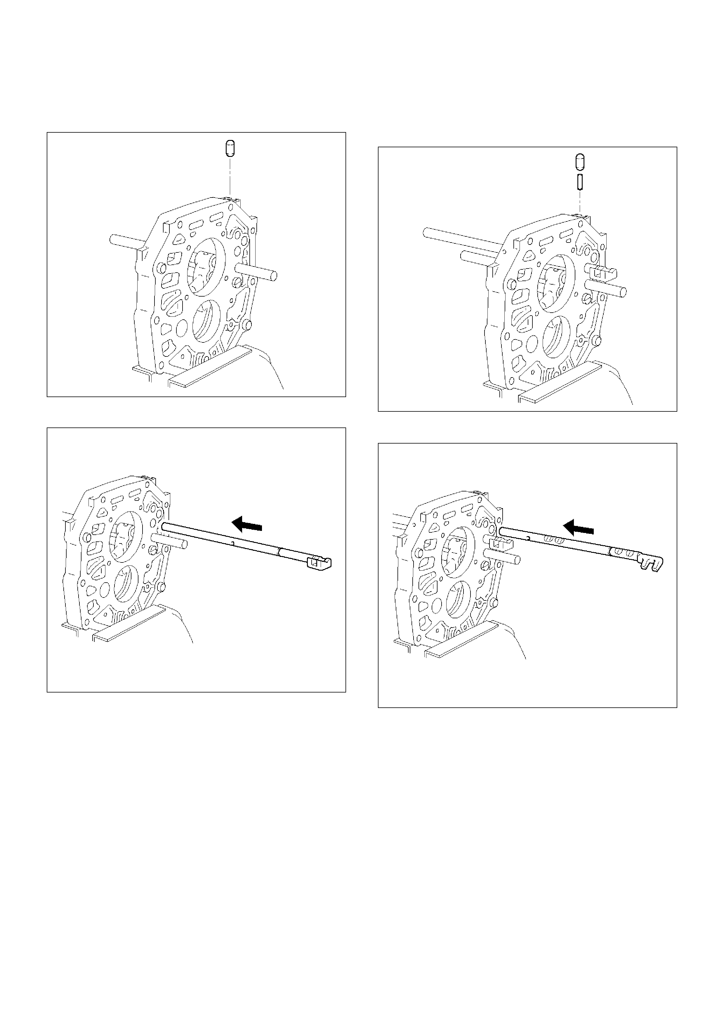
20. Install the reverse shift rod.
1. Install the reverse shift arm No.1 compression
spring and ball to the reverse shift arm No.1.
226RW125
2. Install the reverse shift rod from the rear side by
pushing the ball on using a screwdriver.
226RW126
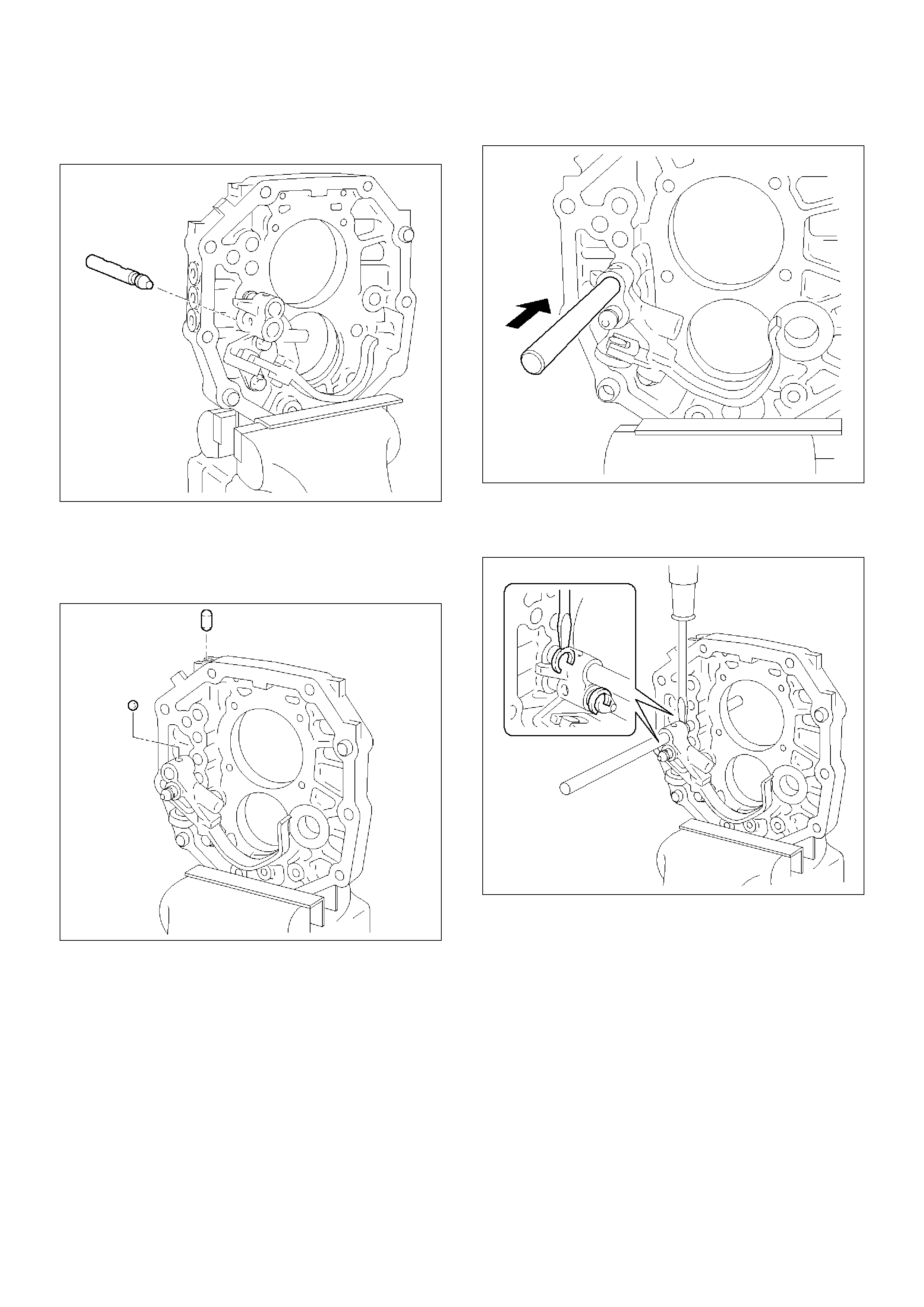
21. Install the reverse-5th shift rod.
1. Install the reverse shift arm No.1 lock ball to the
reverse shift arm No.1.
2. Install the interlock pin to the intermediate plate.
226RW039
3. Put in the reverse-5th shift rod from the front.
226RW011
4. Using a screwdriver and a hammer, install the 2
new shift rod snap rings to the 5th-reverse shift
rod and reverse shift rod.
226RW037
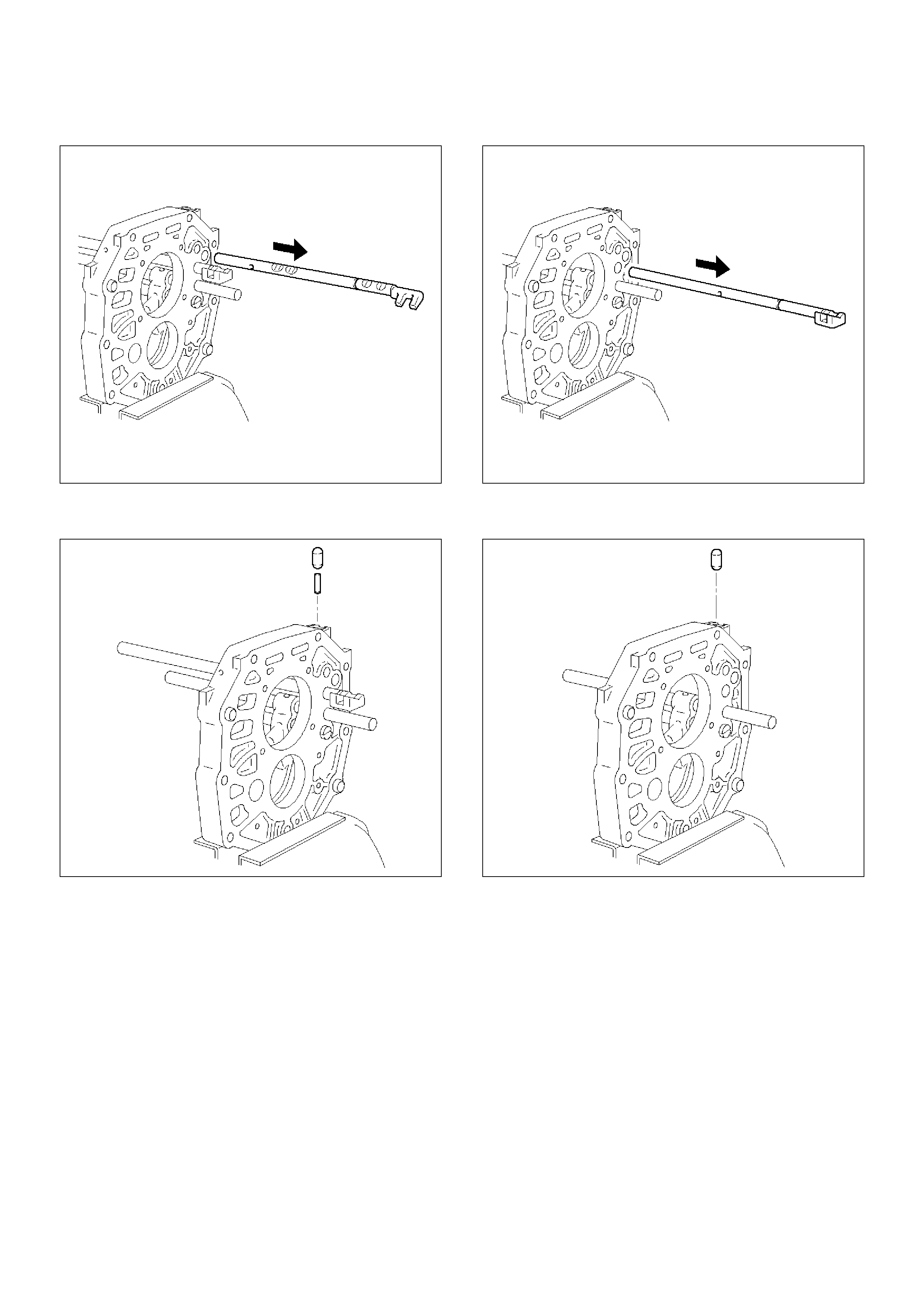
22. Install 1st–2nd shift rod.
1. Install the interlock pin to the intermediate plate.
226RW042
2. Put in the 1st–2nd shift rod from the rear.
226RW044
23. Install 3rd–4th shift rod.
1. Install the straight pin and interlock pin to the
intermediate plate.
226RW043
2. Put in the 3rd–4th shift rod from the rear.
226RW046
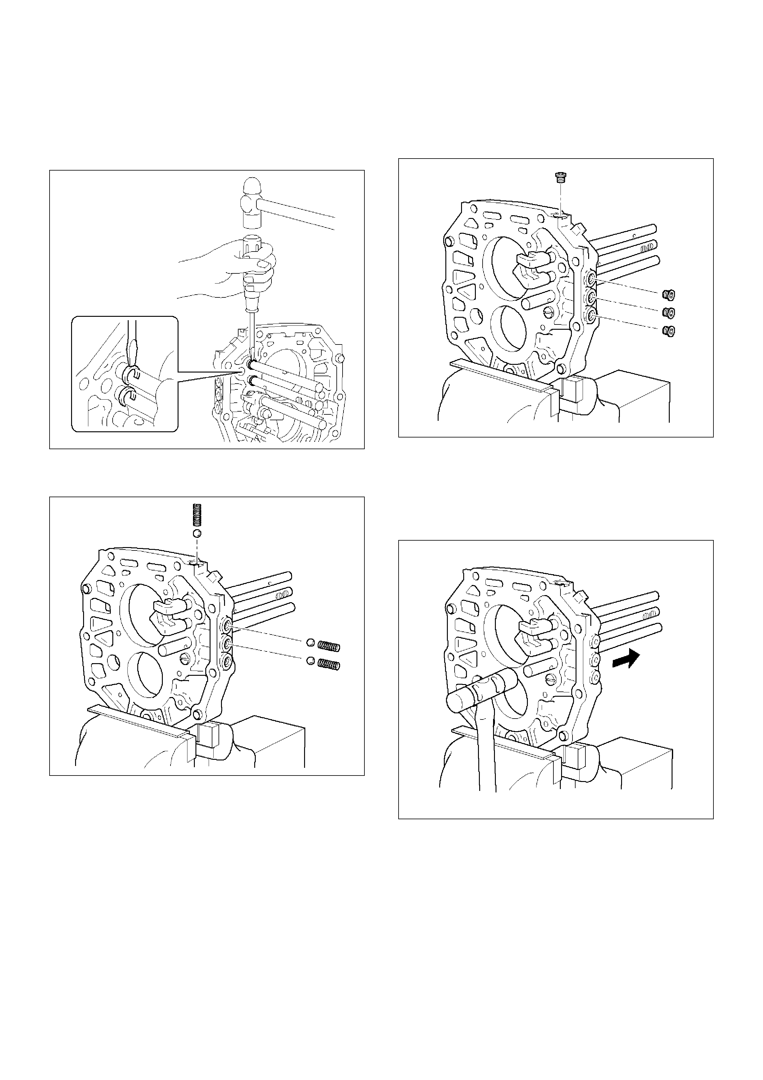
24. Install the interlock parts.
1. Using a screwdriver and hammer, 2 new shift
rod snap rings to the 1st–2nd and 3rd–4th shift
rod.
226RW051
2. Install the 3 shift detent ball and springs to the
intermediate plate.
226RW049
3. Clean up the plug hole.
4. Apply sealant to the plug threads.
sealant: THREE BOND 1344 or equivalent
5. Using a torx socket wrench(T40), install and
torque the 4 plugs.
Torque: 19N·m (1.9kg·m/14lbft)
226RW050
25. Install mainshaft assembly.
NOTE: Coat all parts with gear oil before installing
them.
1. Using a plastic hammer, tap the 5th-reverse shift
rod at the reverse shift.
226RW180
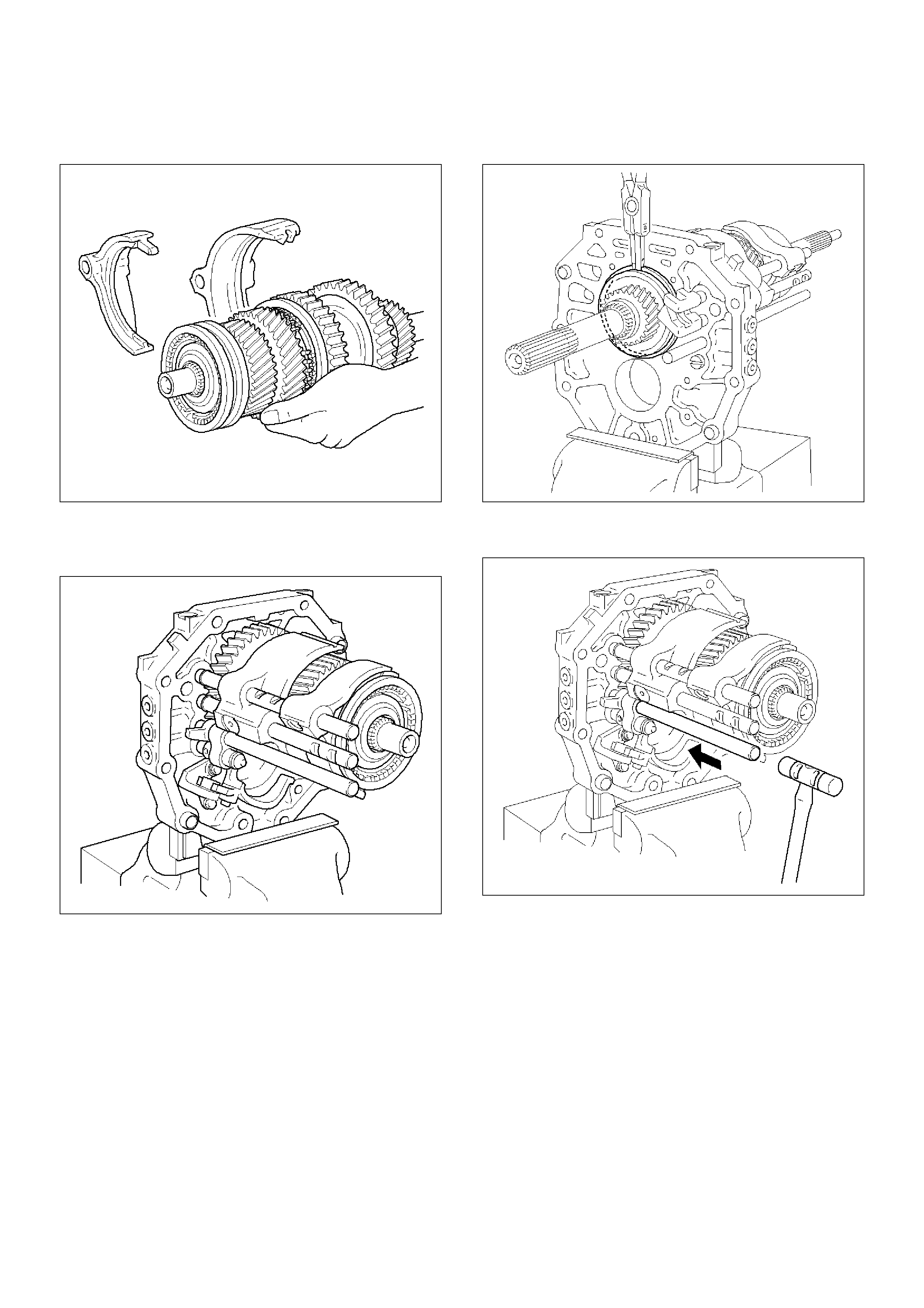
2. Install the shift arm No.1 and No.2 to the
mainshaft.
226RW010
3. Using a plastic hammer, tap the intermediate
plate and install the mainshaft. Through the
shift arm No.1 and No.2 to the shift rod.
226RW009
4. Using a snap ring expander, install the snap
ring.
226RW035
5. Using a plastic hammer, tap the 5th-reverse shift
rod at the neutral shift.
226RW008
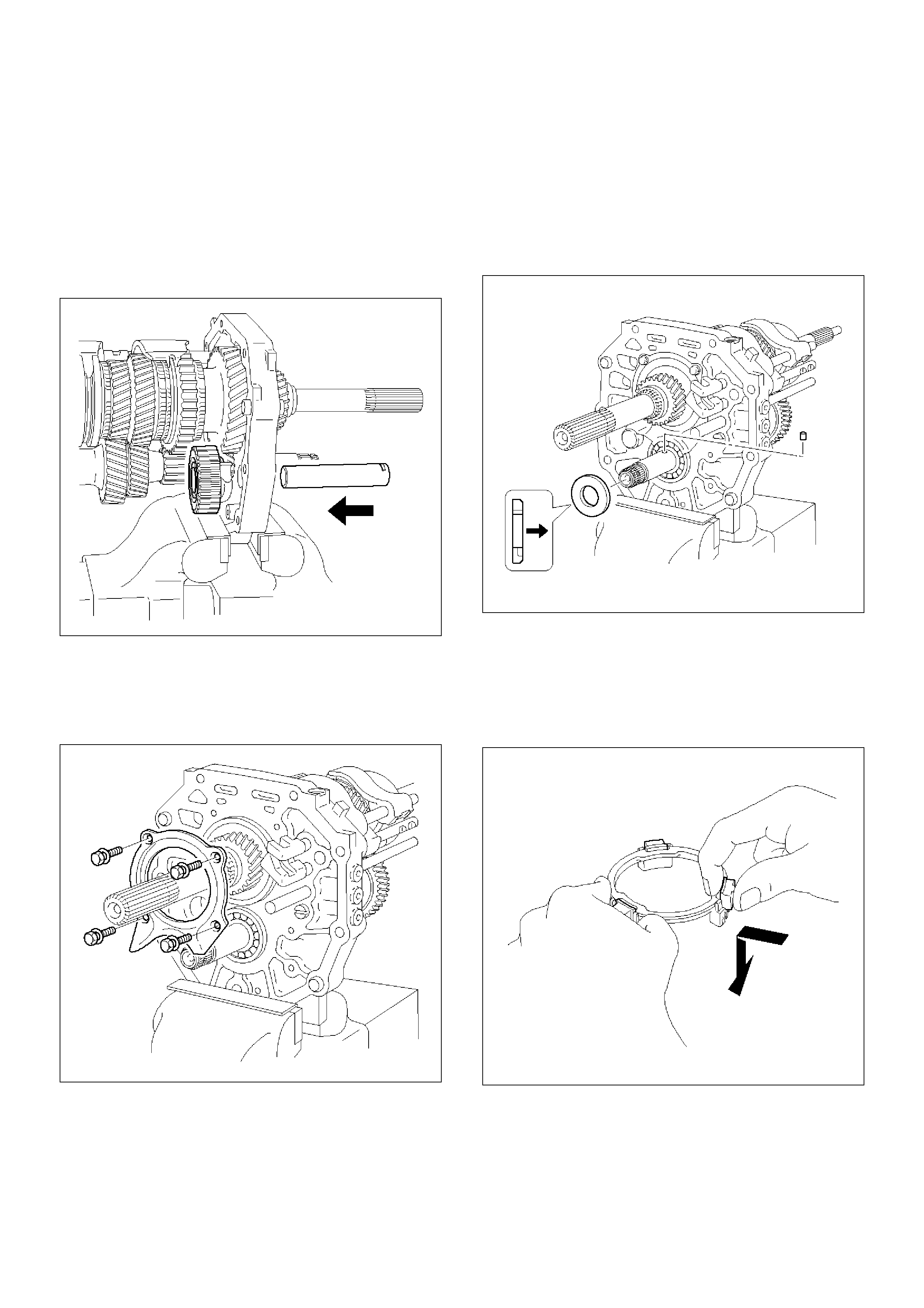
26. Install the top gear shaft.
1. Align the projection of the hub No.2 with the
synchronizer ring slots, and install the top gear
shaft assembly to the mainshaft.
2. Check that the gear rotates smoothly.
226RW006
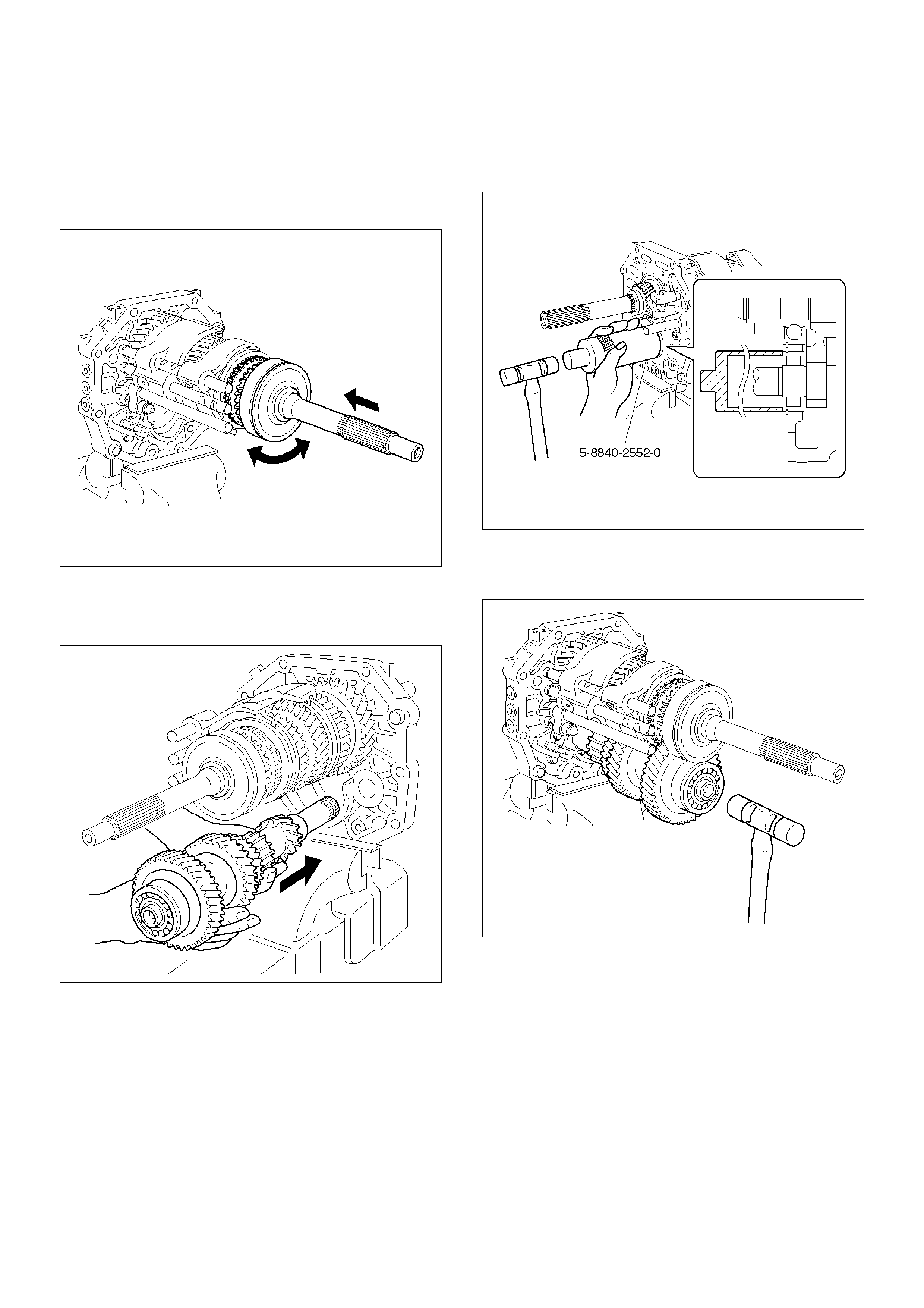
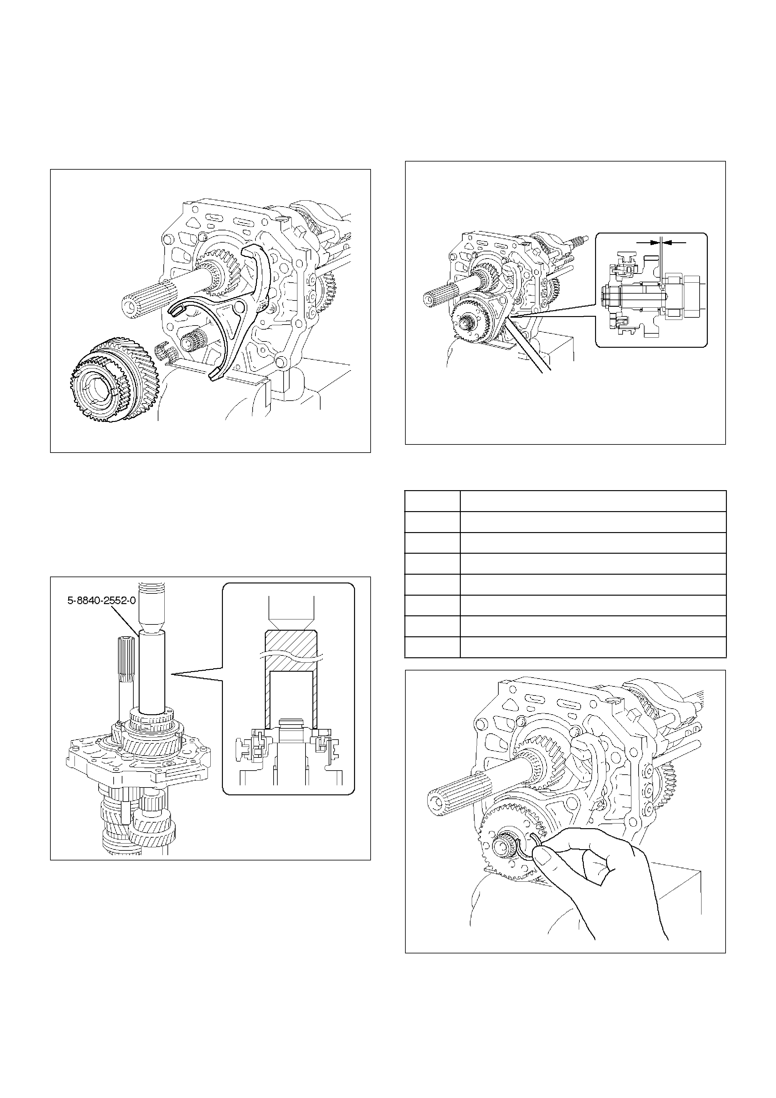
27. Install the counter gear shaft.
1. Temporarily install the counter gear shaft to the
intermediate plate.
226RW028
2. Using installer 5–8840–2552–0 (J–42796) and a
hammer, drive in the center bearing as shown.
NOTE: Outer race snap ring groove toward rear.
226RW192
Reference: Drive in the counter rear bearing
by tapping on the front end of the counter
shaft.
226RW022
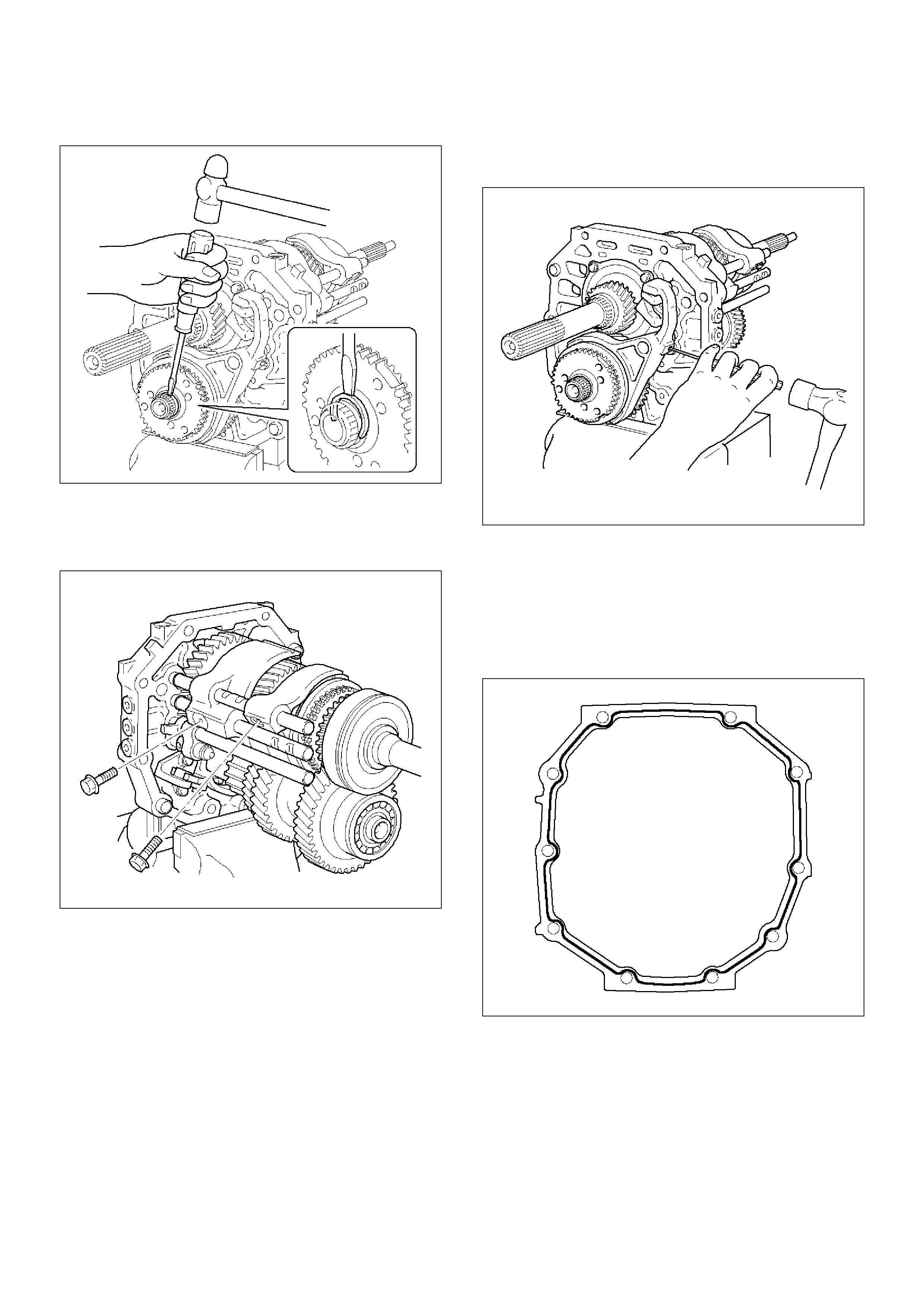
28. Install the reverse idle gear.
1. Install the reverse idle gear and reverse idle
gear shaft.
NOTE:
• Insert the reverse idle gear shaft with the slot toward
rear.
• Install the reverse idle gear with the reverse shift arm
No.2.
226RW019
29. Install the bearing plate.
1. Align the bearing plate to groove of the reverse
idle gear shaft.
Torque: 13N·m (1.3kg·m/113lbin)
226RW016
30. Install the 5th gear thrust washer.
1. Install the 5th gear thrust washer pin to the
counter gear shaft.
2. Install the 5th gear thrust washer to the counter
gear shaft.
NOTE: Thrust washer must be assembled with the
chamfered face of the washer toward the front.
226RW185
31. Install the counter 5th gear.
1. Install the 3 inserts and 3 compression springs
to the reverse block ring.
Reference: Push the 3 inserts with the 3
compression springs to the reverse
synchronizer ring.
226RW120
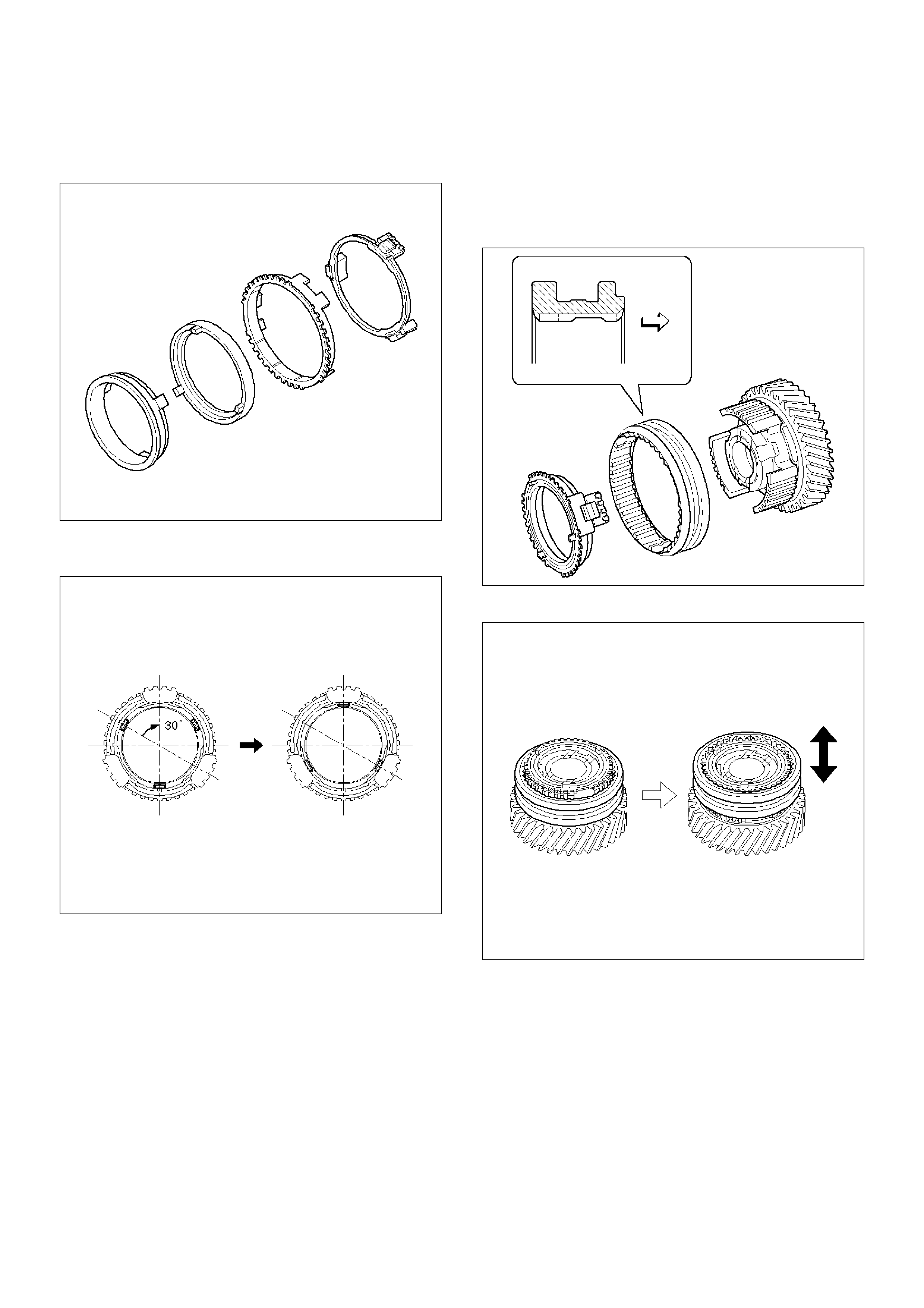
2. Install the synchronizer outer ring, synchronizer
cone ring, and synchronizer pull ring to the
reverse block ring.
226RW121
3. Turn to 30 degree the reverse synchronizer pull
ring.
226RW080
4. Install the hub sleeve No.3 and reverse block
ring set to the counter 5th gear.
NOTE: Check the hub sleeve No.3 direction, as shown.
Reference: While pushing the 3 inserts,
install the synchronizer ring assembly to the
hub sleeve No.3.
226RW184
5. Slide the hub sleeve No.3.
226RW123
6. Install the counter 5th gear bearing, counter 5th
gear and reverse block ring set to the counter
gear shaft, through the 5th reverse shift arm to
the 5th reverse shift rod.
220RW101
7. Using installer 5–8840–2552–0 (J–42796) and a
press, install counter 5th gear spline piece.
NOTE:
• Align the projection of the cone ring to the holes of
the 5th gear spline piece.
• Check that the gear rotates smoothly.
226RW193
8. Using thickness gauge, measure the counter
5th gear thrust clearance.
Standard: 0.10–0.35mm (0.004–0.014in)
220RW100
9. Select a snap ring that will allow minimum axial
play.
226RW027
Mark Thickness
A 2.80–2.85 (0.110–0.112in)
B 2.85–2.90 (0.112–0.114in)
C 2.90–2.95 (0.114–0.116in)
D 2.95–3.00 (0.116–0.118in)
E 3.00–3.05 (0.118– 0.120 in)
F 3.05 – 3.10 (0.120 –0.122in)
G 3.10–3.15 (0.122–0.124in)
10. Install the new snap ring.
226RW026
32. Install the shift arm bolts.
1. Install and torque the 2 shift arm bolts.
Torque: 20N·m (2.0kg·m/14lbft)
226RW023
33. Install the shift arm slotted pin.
1. Using a pin punch and a hammer, drive in the
slotted pin to the shift arm.
226RW025
34. Install the transmission case.
1. Clean up the fitting surface.
2. Apply recommended liquid gasket (THREE
BOND 1281 or equivalent), as shown.
NOTE:
• Don't dry the liquid gasket.
220RW024
3. Stand the transmission by the wood blocks.
4. Using a plastic hammer, tap the transmission
case and attach it to the intermediate plate.
NOTE: Be careful not to add over force to bearing.
220RW022
5. Using a snap ring expander, install the front
bearing shaft snap ring (1) and counter gear
shaft bearing snap ring (2).
226RW004
6. Turn over the transmission.
35. Install the front cover.
1. Clean up the fitting surface.
2. Apply recommended liquid gasket (THREE
BOND 1281 or equivalent), as shown.
NOTE:
• Don't dry the liquid gasket.
220RW025
3. Clean up and dry the bolts.
4. Apply thread sealant (THREE BOND 1344 or
equivalent) to the 8 bolts.
5. Using 8 bolts, install the front cover to the
transmission case.
Torque: 17N·m (1.7kg·m/12lbft)
NOTE:
• Tighten the all bolts evenly.
• Be careful not to damage the oil seal.
220RW018
6. Check that the top gear shaft and mainshaft
rotate.
36. Install the transfer adapter.
1. Clean up the fitting surface.
2. Apply recommended liquid gasket (THREE
BOND 1281 or equivalent), as shown.
NOTE:
• Don't dry the liquid gasket.
220RW026
3. Using a plastic hammer, tap the transfer adapter
and attach it to the intermediate plate.
220RW034
4. Using 10 bolts, install the transfer adapter.
Torque: 37N·m (3.8kg·m/27lbft)
NOTE:
• Tighten the all bolts evenly.
• Don't damage the lip of the oil seal.
• Install the wire clamp (9) to the transfer adapter.
220RW083
37. Install the gear control box.
1. Align the projection of the shift lever housing to
the shaft rod groove, and install the gear control
rod.
230RW003
2. Using a pin punch and hammer, drive in the
slotted spring pin (2) to the shift lever housing.
NOTE: Be carefull not to drop the slotted spring pin.
230RW002
3. Apply sealant (THREE BOND 1344 or
equivalent) to the plug (1) thread.
4. Using hexagon wrench, install and torque the
plug (1).
Torque: 18N·m (1.8kg·m/13lbft)
220RW010
5. Clean up the bolts and bolt hole.
6. Using 6 bolts, install the gear control box
through the gasket.
Torque 18N·m (1.8kg·m/13lbft)
(6VE1)
230RW001
(4JX1)
220RW097
38. Install clutch housing.
1. Install the clutch housing to the transmission
case.
Torque: 36N·m (3.7kg·m/27lbft)
NOTE: Tighten the all bolts evenly.
241RW001
39. Install the switches.
1. Install the new gasket to the 1st and 2nd switch.
2. Install the 1st and 2nd switch assembly (8).
Torque: 39N·m (4.0kg·m/29lbft)
3. Install the new gasket to the backup light switch.
4. Install the backup light switch assembly (6).
Torque: 44N·m (4.5kg·m/33lbft)
5. Install the new gasket to the neutral switch.
6. Install the neutral switch (7) to the transfer
adapter (4JX1).
Torque: 37N·m (3.8kg·m/27lbft)
(4JX1)
220RW093
40. Install the clutch release bearing (3) and clutch shift
fork (5).
1. Apply the clutch release grease.
1. Fitting surface of the cylinder push rod.
2. Fitting surface of the release bearing hub.
3. The hole of the fork split pin (4).
2. Apply the clutch release grease.
1. The spline surface of the top gear shaft.
3. Install the clutch shift fork (5).
4. Install the snap pin.
5. Install the clutch release bearing (3) to the
clutch shift fork (5).
220RW086

41. Install the drain plug and filler plug.
1. Install the drain plug (1) through the new gasket.
Torque: 37N·m (3.8kg·m/27lbft)
2. Install the filler plug (2) through the new gasket.
Reference: Plug after the gear oil fill in.
Torque: 37N·m (3.8kg·m/27lbft)
(6VE1)
220RW007

Main Data and Specifications
General Specifications
Transmission type Fully synchronized forward and reverse gears
Control method Direct control with the gear shift lever on the floor
Gear ratio 1st 3.954
2nd 2.330
3rd 1.436
4th 1.000
5th 0.788
Rev 3.918
Oil capacity lit (US qt) 2.7 (2.86)
Type of lubricant Engine oil : Refer to the chart in “SECTION 0B”
Torque Specifications
E07RW049
Torque Specifications (Cont'd)
E07RW050
Torque Specifications (Cont'd)
E07RW051
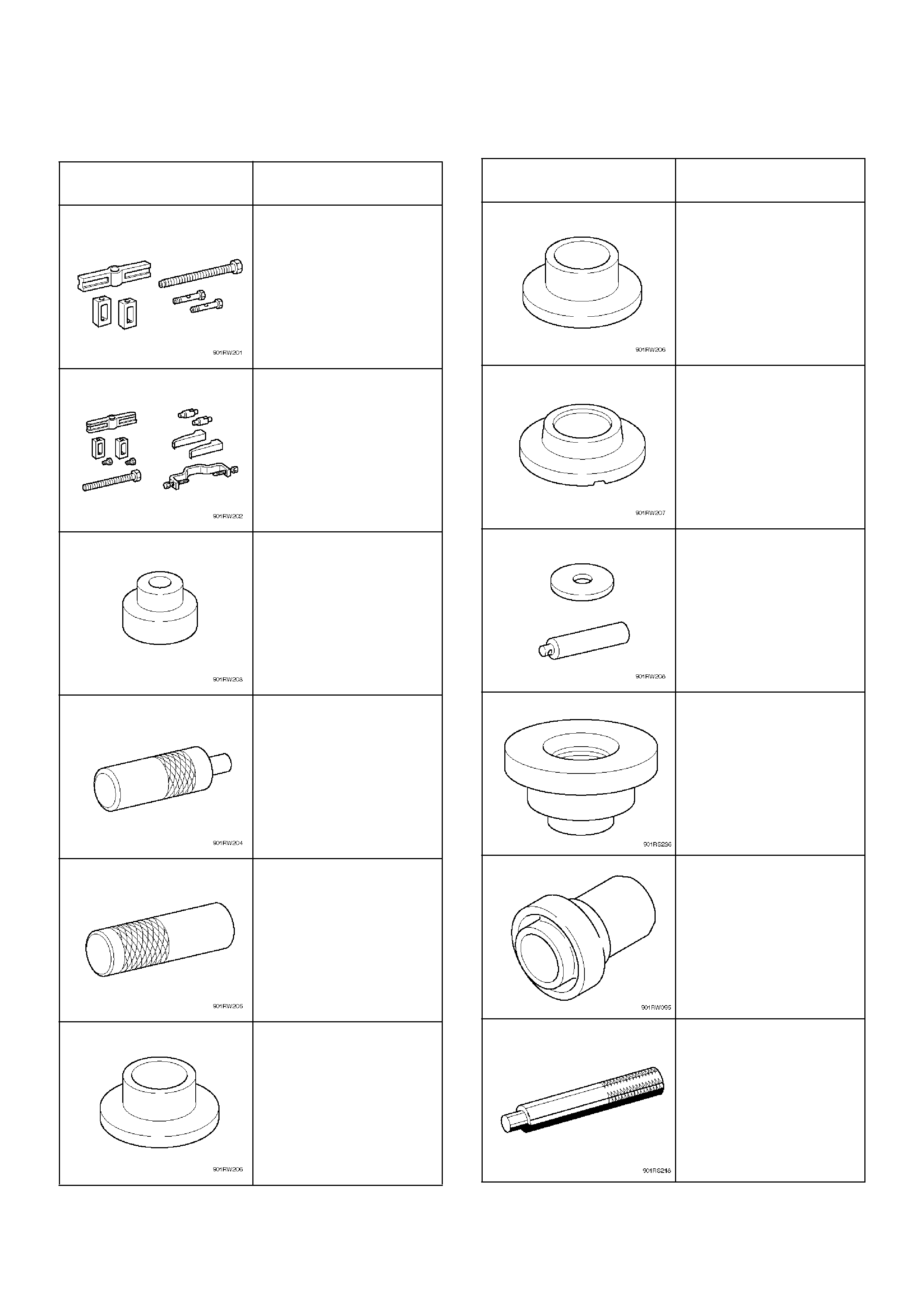
Special Tools
ILLUSTRATION TOOL NO.
TOOL NAME
5–8840–2550–0
(J–42794)
Gear spline pieace
remover
5–8840–2551–0
(J–42795)
Center bearing remover
5–8840–2560–0
(J–42988)
Attachment
5–8840–2552–0
(J–42796)
Counter gear shaft center
bearing installer
5–8840–2553–0
(J–42797)
Clutch hub (No.2)
installer
5–8840–2554–0
(J–42798)
Clutch hub (No.1)
installer
5–8840–2555–0
(J–42799)
Installer
5–8840–2556–0
(J–42800)
Counter gear shaft front
bearing installer
5–8840–2559–0
(J–42904)
Top gear shaft front
bearing installer
5–8840–2557–0
(J–42801)
Front rerainer oil seal
installer
5–8840–2558–0
(J–42802)
Transfer adapter oil seal
installer
5–8840–0007–0
(J–8092)
Driver handle
ILLUSTRATION TOOL NO.
TOOL NAME
Special Tools (Cont'd)
ILLUSTRATION TOOL NO.
TOOL NAME
5–8840–0015–0
(J–22912–01)
Bearing separator